

Page 1

Dell EMC PowerEdge XR11 and XR12
Technical Guide
Par t N umb er: E7 3S Ser ies
Reg ula tor y T ype : E 73S 001
Jul y 2 021
Rev . A 00
Page 2

Notes, cautions, and warnings
NOTE: A NOTE indicates important information that helps you make better use of your product.
CAUTION: A CAUTION indicates either potential damage to hardware or loss of data and tells you how to avoid
the problem.
WARNING: A WARNING indicates a potential for property damage, personal injury, or death.
© 2021 Dell Inc. or its subsidiaries. All rights reserved. Dell, EM C, and other trademarks are trademarks of Dell Inc. or its subsidiaries. Oth er
trademarks may be trademarks of their respective owners.
Page 3

Contents
Chapter 1: System overview.......................................................................................................... 6
Key workloads...................................................................................................................................................................... 6
New technologies................................................................................................................................................................ 6
Chapter 2: System features.......................................................................................................... 8
Chapter 3: Chassis views and features.........................................................................................10
Chassis views......................................................................................................................................................................10
Front view of XR11 front accessed chassis........................................................................................................... 10
Front view of XR11 rear accessed chassis.............................................................................................................. 11
Front view of XR12 front accessed chassis...........................................................................................................12
Front view of XR12 rear accessed chassis.............................................................................................................13
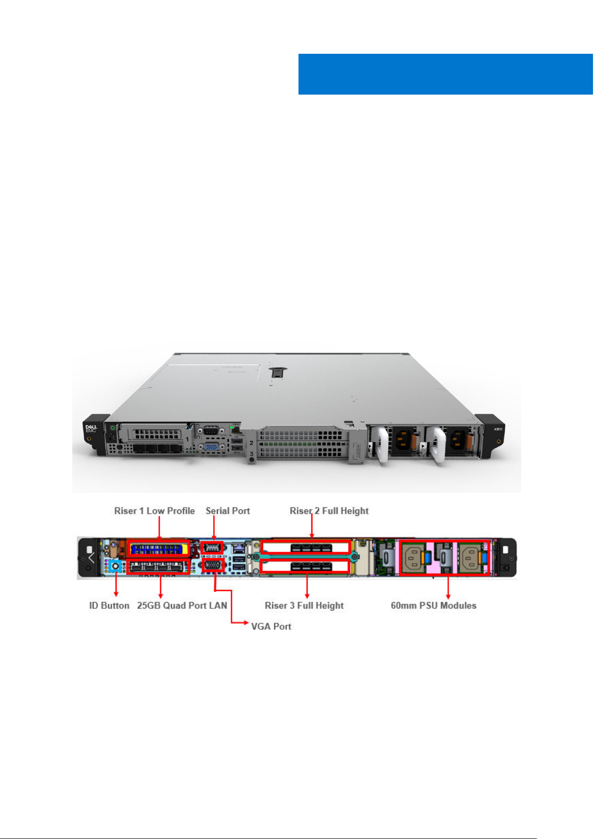
Rear view of XR11 front accessed chassis............................................................................................................. 14
Rear view of XR11 rear accessed chassis...............................................................................................................14
Rear view of XR12 front accessed chassis ........................................................................................................... 15
Rear view of XR12 rear accessed chassis.............................................................................................................. 15
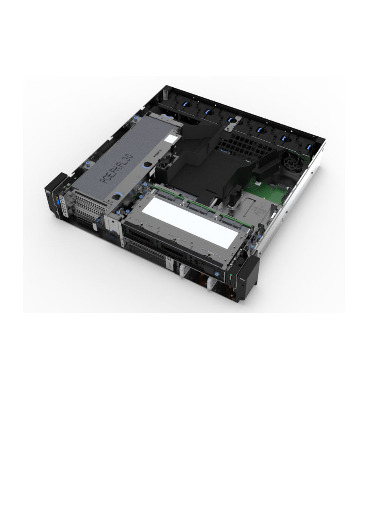
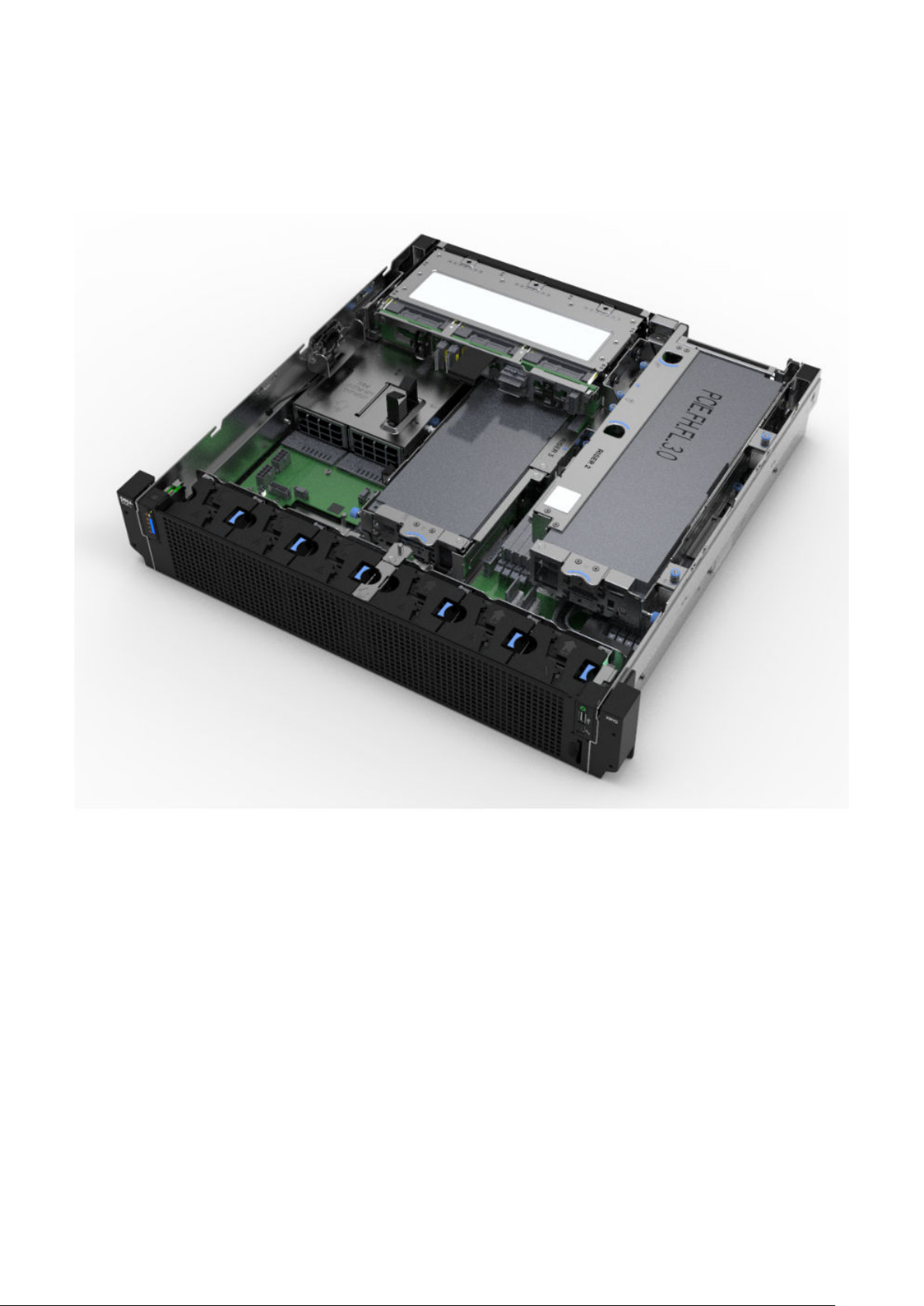
Inside the XR11 front accessed chassis.................................................................................................................. 16
Inside the XR11 rear accessed chassis.................................................................................................................... 18
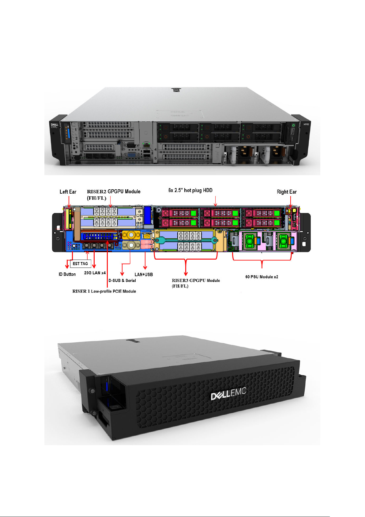
Inside the XR12 front accessed chassis................................................................................................................. 20
Inside the XR12 rear accessed chassis...................................................................................................................22
Quick Resource Locator (QRL)................................................................................................................................23
Chapter 4: Processor.................................................................................................................. 25
Processor features .......................................................................................................................................................... 25
Supported processors for XR11 and XR12................................................................................................................... 25
Chapter 5: Memory subsystem.................................................................................................... 27
Supported memory............................................................................................................................................................27
Chapter 6: Storage......................................................................................................................28
Supported drives............................................................................................................................................................... 28
Internal storage configuration matrix for XR11...........................................................................................................28
Internal storage configuration matrix for XR12..........................................................................................................29
External storage................................................................................................................................................................ 30
Chapter 7: Expansion cards and expansion card risers..................................................................31
Expansion cards and risers for the PowerEdge XR11 system................................................................................. 31
Expansion card installation guidelines..................................................................................................................... 31
Expansion cards and risers for the PowerEdge XR12 system................................................................................ 34
Expansion card installation guidelines.....................................................................................................................34
Chapter 8: Power, thermal, and acoustics................................................................................... 39
Power for XR11 and XR12................................................................................................................................................ 39
Thermal for XR11 and XR12.............................................................................................................................................40
Contents 3
Page 4

Acoustics.............................................................................................................................................................................40
Acoustical design for XR11 and XR12......................................................................................................................40
Chapter 9: Rack, rails, and cable management.............................................................................42
Rails information................................................................................................................................................................ 42
Sliding rails in 2-post rack......................................................................................................................................... 43
Sliding rails in 4-post rack......................................................................................................................................... 44
Sliding rails in Pelican transit case...........................................................................................................................46
Cable Management Arm.................................................................................................................................................. 46
Strain Relief Bar................................................................................................................................................................. 47
Chapter 10: Supported Operating Systems.................................................................................. 48
Chapter 11: Dell EMC OpenManage systems management............................................................ 49
Server and Chassis Managers........................................................................................................................................ 50
Dell EMC consoles............................................................................................................................................................ 50
Automation Enablers........................................................................................................................................................ 50
Integration with third-party consoles...........................................................................................................................50
Connections for third-party consoles.......................................................................................................................... 50
Dell EMC Update Utilities................................................................................................................................................50
Dell resources.....................................................................................................................................................................50
Chapter 12: Dell Technologies Services .......................................................................................52
Dell EMC ProDeploy Enterprise Suite ......................................................................................................................... 52
Dell EMC ProDeploy Plus...........................................................................................................................................53
Dell EMC ProDeploy....................................................................................................................................................53
Basic Deployment........................................................................................................................................................ 53
Dell EMC Server Configuration Services............................................................................................................... 53
Dell EMC Residency Services................................................................................................................................... 53
Dell EMC Remote Consulting Services........................................................................................................................ 53
Dell EMC Data Migration Service..................................................................................................................................53
Dell EMC ProSupport Enterprise Suite........................................................................................................................ 53
Dell EMC ProSupport Plus for Enterprise................................................................................................................... 54
Dell EMC ProSupport for Enterprise............................................................................................................................ 54
Dell EMC ProSupport One for Data Center................................................................................................................55
ProSupport for HPC.........................................................................................................................................................55
Support Technologies...................................................................................................................................................... 56
Dell Technologies Education Services..........................................................................................................................57
Dell Technologies Consulting Services.........................................................................................................................57
Dell EMC Managed Services...........................................................................................................................................57
Chapter 13: Appendix A. Additional specifications....................................................................... 58
Chassis dimensions........................................................................................................................................................... 58
Chassis weight................................................................................................................................................................... 60
Video specifications.......................................................................................................................................................... 60
USB ports............................................................................................................................................................................60
USB ports specifications for XR11........................................................................................................................... 60
USB ports specifications for XR12...........................................................................................................................61
Power Supply Units for XR11 and XR12........................................................................................................................61
4
Contents
Page 5

Power supply efficiency for XR11 and XR12..........................................................................................................62
Environmental Specifications for XR11 and XR12...................................................................................................... 63
ASHRAE A3/A4/Rugged support restriction for XR11 and XR12.................................................................... 64
Thermal restrictions.................................................................................................................................................... 66
Chapter 14: Appendix B. Standards compliance........................................................................... 69
Chapter 15: Appendix C Additional resources...............................................................................70
Contents 5
Page 6
1
System overview
The Dell™ PowerEdge™ XR11 and XR12 are Dell's latest rugged servers, designed to run complex workloads using highly scalable
memory, I/O, and network options in locations constrained by space or environmental challenges.
The PowerEdge XR11 is a 1-socket, short-depth 1U rugged server.
The PowerEdge XR12 is a 1-socket, short-depth 2U rugged server.
The systems feature the 3rd Generation Intel Xeon Scalable Processor with up to 8 DIMMs, PCI Express® (PCIe) 4.0 enabled
expansion slots, and a choice of network interface technologies to cover NIC. The PowerEdge XR11 and XR12 systems are
unique platforms designed to optimize computing at the edge with performance in mind. The systems are well suited to operate
at high temperatures in harsh or space-constrained environments, and are capable of handling demanding processing workloads
and applications such as for the Telecom, Military and Defense industries, as well as, for the commercial sector.
Topics:
• Key workloads
• New technologies
Key workloads
There are a diverse set of applications that operate at the Edge and each of these applications has a different set of
requirements.
● Retail Applications - Built with a minimum footprint and enterprise compute to optimize expensive retail space and deliver
a targeted virtual experience, including video surveillance analytics, point of sale analytics and IoT device aggregation and
analytics
● Telco / 5G - Compact and rugged design capable of supporting accelerators for remote private networks requiring
AI/ML/DL type workloads. Use cases include MEC, CDN and VRAN
● Military - Reliable DC power in a hardened chassis to support mobile data centers deployed globally to collect and analyze
reconnaissance data
New technologies
Table 1. New technologies featured on XR11 and XR12
Technology Detailed description
3rd Generation Intel® Xeon
Scalable Processor
● 10nm process technology
● Maximum of 36 cores
● Maximum of 3.5 GHz
● Maximum of 64 lanes of PCI Express 4.0 links capable of 16 GT/s
● Maximum TDP: 225 W
Consult the Processor section for specific SKU details.
NOTE: TDP support will vary based on the maximum operating temperature.
3200 MT/s DDR4 Memory
Persistent Memory 128 GB Intel Optane DC Persistent Memory 200 Series support on two configurations:
6 System overview
● Up to 8 DDR4 channels with 1 DPC; 8 DIMMs in total
● Speed up to 3200 MT/s (configuration-dependent)
● Supports DDR4 ECC RDIMM (max: 64 GB) and DDR4 ECC LRDIMM (max: 128 GB)
Number of DDR4 DIMMs plus number of Intel Optane Persistent Memory 200 Series
DIMMs
Page 7

Table 1. New technologies featured on XR11 and XR12 (continued)
Technology Detailed description
● 4+4
● 6+1
Chassis Orientation The XR11 and XR12 have two chassis options:
1. Rear accessed chassis also called Normal Airflow (NAF) chassis, where power supplies
and network cards are in the rear
2. Front accessed chassis also called Reverse Airflow (RAF) chassis, where power
supplies and network cards are in the front
The location of the control panel changes with the chassis orientation.
iDRAC9 w/ Lifecycle Controller The embedded systems management solution for Dell servers features hardware and
firmware inventory and alerting, in-depth memory alerting, faster performance, a
dedicated gigabit port and many more features.
Power Supplies
● 60 mm dimension (new PSU form factor for new generation of servers)
● Platinum 800 W (WRAC and MM 240 V)
● *1100 W -48 V DC
● *Platinum 1400 W (WRAC and MM 240 V)
NOTE: *These PSUs are available in Reverse Airflow design for use in Front Accessed
chassis configuration and in Normal Airflow for use in Rear Accessed configuration.
System overview 7
Page 8
System features
Table 2. System features of XR11 and XR12
Feature XR11 XR12
Processor 1x 3rd Generation Intel® Xeon Scalable Processor 1x 3rd Generation Intel® Xeon Scalable Processor
Chipset Intel Lewisburg PCH (Intel® C620 Series Chipset) Intel Lewisburg PCH (Intel® C620 Series Chipset)
2
Memory
Disk Drives
Storage
Controllers
External Storage
Supported
M.2 SSD
PCIe Slots
8x RDIMM, LRDIMM DDR4 with ECC
Two Intel Optane Persistent Memory 200 series
configurations: Number of DDR4 DIMMs plus number
of Intel Optane Persistent Memory 200 series DIMMs
● 4+4
● 6+1
4x 2.5 - inch - 12 GB SAS, 6 GB SATA
Up to 4x NVMe
● PERC 10.5: H345 (Adapter)
● PERC 11: HBA355i (Adapter), H755 (Adapter)
● External Adapters: H840; HBA355e
● Software RAID: S150
● BOSS-S1 (RAID)
ME484, MD1420 and MD1400 ME484, MD1420 and MD1400
Up to 2x M.2 Boot Optimized Storage Subsystem
(BOSS-S1)
Two riser configuration options:
● 3x PCIe Gen4 (one x8 PCIe Gen4 + two x16 PCIe
Gen4)
● 3x PCIe Gen4 (one x16 PCIe Gen4 + two x16 PCIe
Gen4)
8x RDIMM, LRDIMM DDR4 with ECC
Two Intel Optane Persistent Memory 200 series
configurations: Number of DDR4 DIMMs plus
number of Intel Optane Persistent Memory 200
series DIMMs
● 4+4
● 6+1
6x 2.5-inch - 12 GB SAS, 6 GB SATA
Up to 6x NVMe
● PERC 10.5: H345 (Adapter)
● PERC 11: HBA355i (Adapter), H755 (Adapter)
● External Adapters: H840; HBA355e
● Software RAID: S150
● BOSS-S1 (RAID)
Up to 2x M.2 Boot Optimized Storage Subsystem
(BOSS-S1)
Five riser configuration options:
● 3x PCIe Gen4 (one x8 PCIe Gen4 + two x16
PCIe Gen4)
● 3x PCIe Gen4 (one x16 PCIe Gen4 + two x16
PCIe Gen4)
● 4x PCIe Gen 4 (three x8 PCIe Gen4 + one x16
PCIe Gen 4)
● 4x PCIe Gen 4 (two x8 PCIe Gen 4 + two x16
PCIe Gen 4)
● 5x PCIe Gen4 (five x8 PCIe Gen4)
Integrated LOM 4x 25 GbE SFP+ (Broadcom Thor) 4x 25 GbE SFP+ (Broadcom Thor)
XR11 has two chassis options:
1. Rear Accessed chassis also called Normal Airflow
Chassis
Orientation
8 System features
(NAF) chassis where power supplies and network
cards are in the rear.
NOTE: Network, Serial, VGA, Power supplies
and PCIe Slots are accessible in the rear
of the platform and the Hard Drives, Power
button, Status LED, USB and Management
port are in the front of the system.
XR12 has two chassis options:
1. Rear Accessed chassis also called Normal
Airflow (NAF) chassis where power supplies
and network cards are in the rear.
NOTE: Network, Serial, VGA ports, Power
supplies, Hard drives and PCIe Slots are
accessible in the rear of the platform.
2. Front Accessed chassis also called Reverse
Airflow (RAF) chassis where power supplies
and network cards are in the front.
Page 9

Table 2. System features of XR11 and XR12 (continued)
Feature XR11 XR12
I/O Ports
2. Front Accessed chassis also called Reverse
Airflow (RAF) chassis where power supplies and
network cards are in the front.
NOTE: Power button, Network ports, Serial,
VGA and PCIe Slots are accessible in the
front of the platform and the Hard Drives and
Status LED are in the rear of the system.
The location of the control panel changes with the
chassis orientation.
Rear Accessed/Normal Airflow (NAF) Chassis
● Front:
○ one standard USB 2.0 port
○ one micro USB 2.0 port dedicated to iDRAC
management
● Rear:
○ one standard USB 3.0 port
○ one standard USB 2.0 port
○ one Dedicated 1GbE
○ one Serial port
○ one VGA port
● Internal: one standard USB 3.0 port on Riser 1B
Front Accessed/Reverse Airflow (RAF) Chassis
● Front: one standard USB 3.0 port, one standard
USB 2.0 port, one micro USB 2.0 port dedicated
to iDRAC management, one Dedicated 1GbE, one
Serial port, one VGA port
● Internal: one standard USB 3.0 port on Riser 1B
NOTE: Network, Serial, VGA ports, Power
supplies, Hard drives and PCIe Slots are
accessible in the front of the platform.
Rear Accessed/Normal Airflow (NAF) Chassis
● Front:
○ one standard USB 2.0 port
○ one micro USB 2.0 port dedicated to
iDRAC management
● Rear:
○ one standard USB 3.0 port
○ one standard USB 2.0 port
○ one Dedicated 1GbE
○ one Serial port
○ one VGA port
● Internal: one standard USB 3.0 port on Riser
1B
Front Accessed/Reverse Airflow (RAF) Chassis
● Front: one standard USB 3.0 port, two
standard USB 2.0 ports, one micro USB 2.0
port dedicated to iDRAC management, one
Dedicated 1GbE, one Serial port, one VGA port
● Internal: one standard USB 3.0 port on Riser
1B
Rack Height 1U 2U
Power Supplies
System
Management
Internal GPU
Availability
800 W (WRAC and MM 240 V), *1400 W (WRAC and
240 V), *1100 W (-48 V DC)
NOTE: *These PSUs are also available in reverse
airflow design to support Front Accessed chassis
configurations.
● iDRAC9
● Lifecycle Controller
● OpenManage
● OME Power Manager
● Digital License Key
Up to 2x 70 W (SW/FH/HL) Up to 2x 75 W/150 W (SW) and 2x 300 W
● Hot-plug Drives
● Redundant Cooling
● Hot-plug Redundant Power Supplies (1+1)
800 W (WRAC and MM 240 V), *1400 W (WRAC
and 240 V), *1100 W (-48 V DC)
● iDRAC9
● Lifecycle Controller
● OpenManage
● OME Power Manager
● Digital License Key
(DW/FH/FL) based on riser configuration
● Hot-plug Drives
● Redundant Cooling
● Hot-plug Redundant Power Supplies (1+1)
NOTE: *These PSUs are also available in
reverse airflow design to support Front
Accessed chassis configurations.
System features 9
Page 10
Chassis views and features
Topics:
• Chassis views
Chassis views
Front view of XR11 front accessed chassis
3
Figure 1. XR11 Front accessed chassis front views
10 Chassis views and features
Page 11
Front view of XR11 rear accessed chassis
Figure 2. XR11 Rear accessed chassis front view, no bezel
Figure 3. XR11 Rear accessed chassis view with front bezel
Chassis views and features
11
Page 12
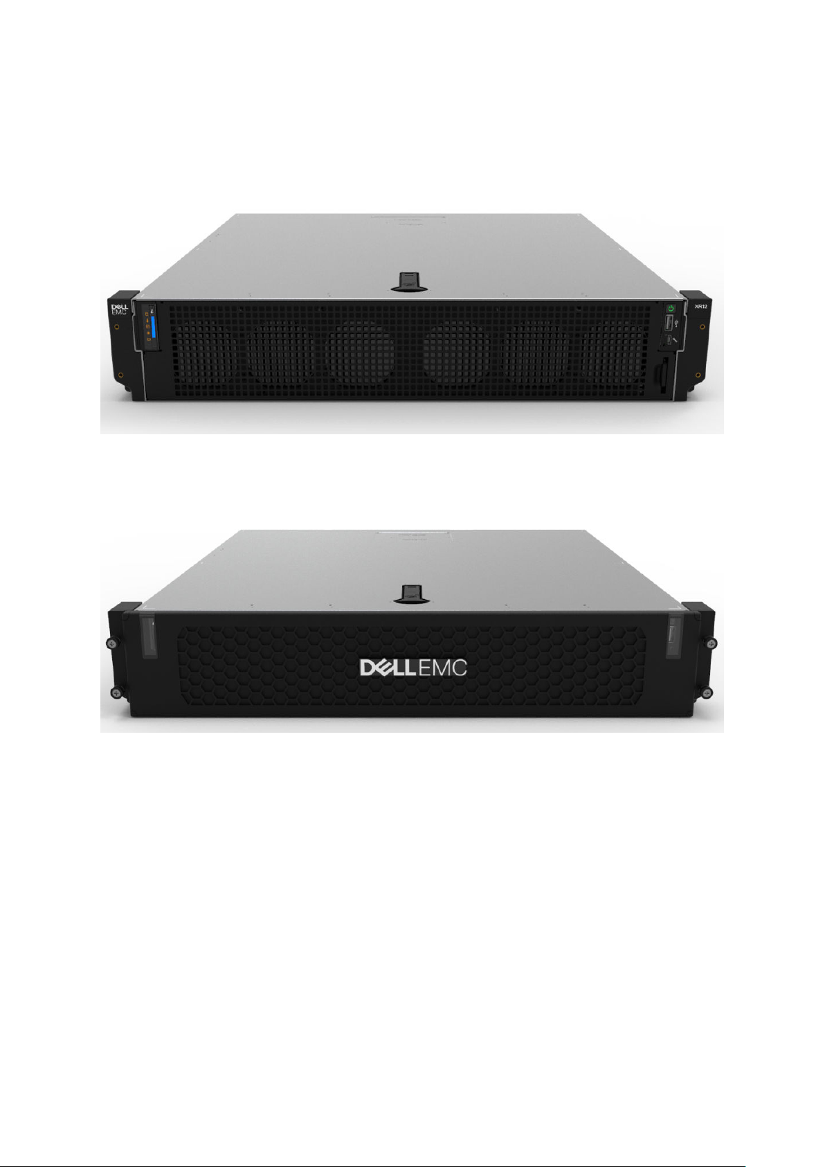
Front view of XR12 front accessed chassis
Figure 4. XR12 Front accessed chassis front views
Figure 5. XR12 Front accessed chassis, front-side view with filter bezel
12
Chassis views and features
Page 13
Front view of XR12 rear accessed chassis
Figure 6. XR12 Rear accessed chassis front view, no bezel
Figure 7. XR12 Rear accessed chassis view with front bezel
Chassis views and features
13
Page 14
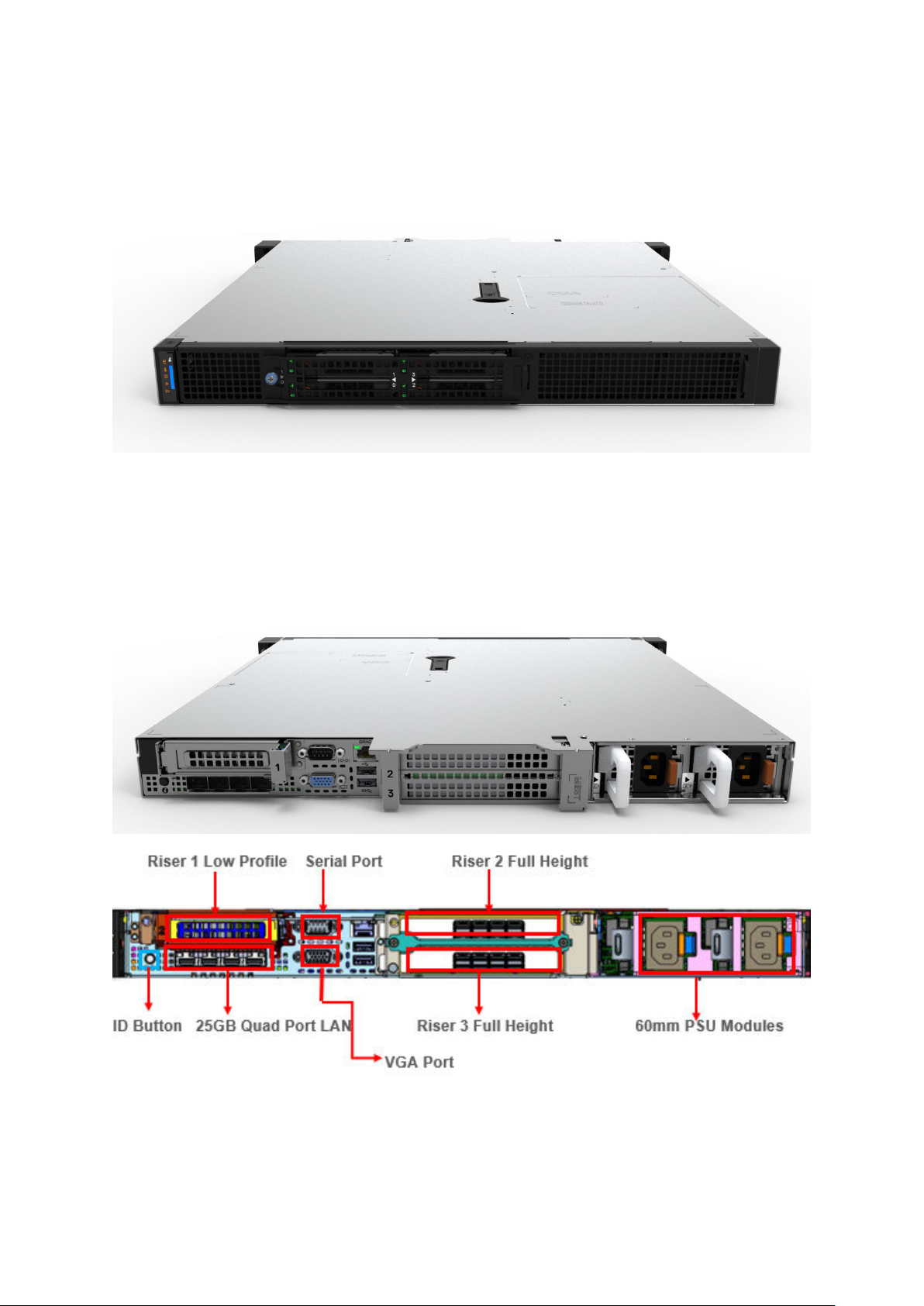
Rear view of XR11 front accessed chassis
Figure 8. XR11 Front accessed chassis rear view
Rear view of XR11 rear accessed chassis
Figure 9. XR11 Rear accessed chassis rear views
14
Chassis views and features
Page 15
Rear view of XR12 front accessed chassis
Figure 10. XR12 Front accessed chassis rear view
Rear view of XR12 rear accessed chassis
Figure 11. XR12 Rear accessed chassis rear views
Chassis views and features
15
Page 16
Inside the XR11 front accessed chassis
Figure 12. XR11 Front accessed chassis internal view (no bezel)
16
Chassis views and features
Page 17
Figure 13. XR11 Front accessed chassis internal exploded view (rear to front)
Chassis views and features
17
Page 18
Inside the XR11 rear accessed chassis
Figure 14. XR11 Rear accessed chassis internal view (no bezel)
18
Chassis views and features
Page 19
Figure 15. XR11 Rear accessed chassis internal exploded view (no bezel)
Chassis views and features
19
Page 20
Inside the XR12 front accessed chassis
Figure 16. XR12 Front accessed chassis internal front view (no bezel)
20
Chassis views and features
Page 21
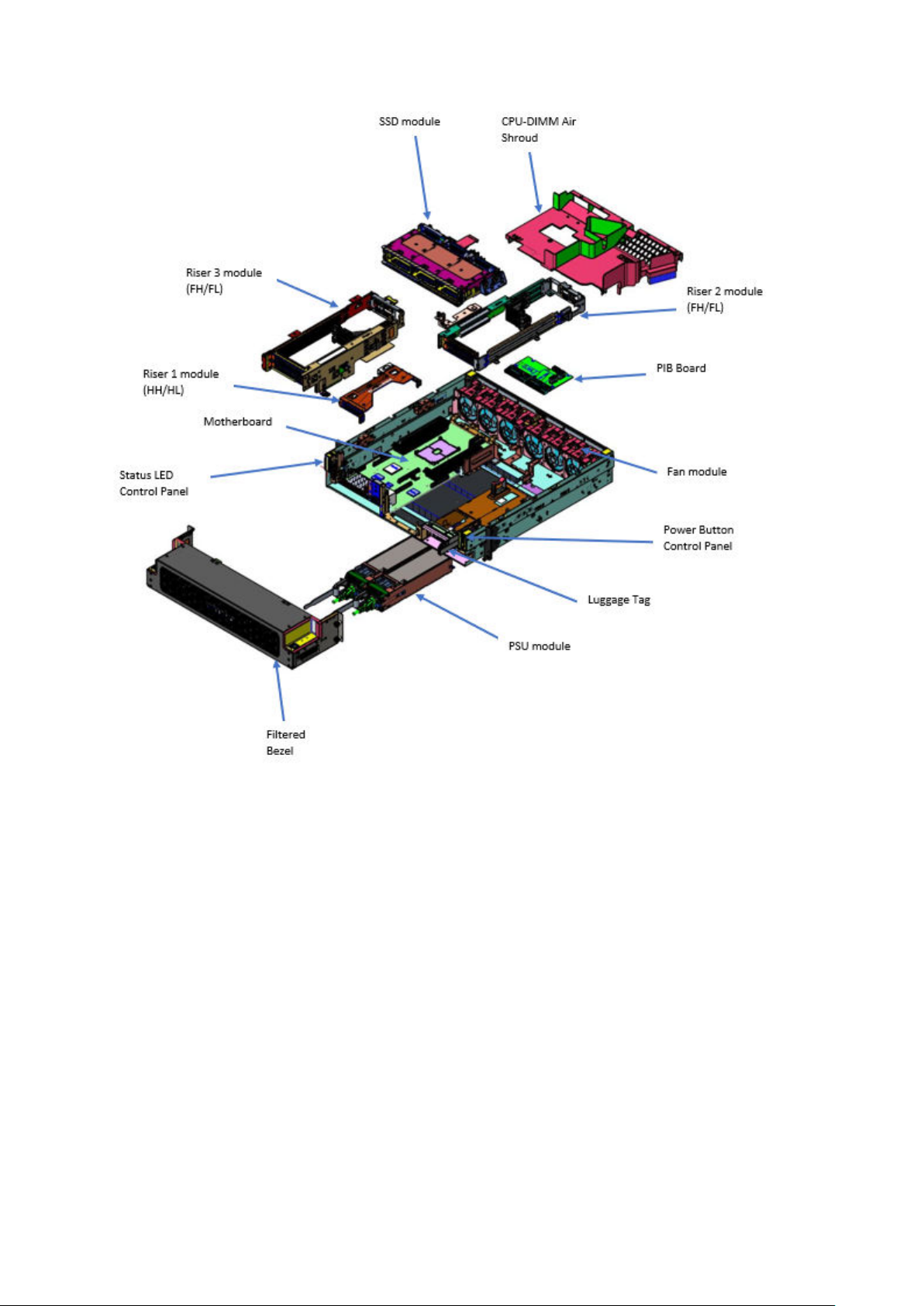
Figure 17. XR12 Front accessed chassis internal exploded view
Chassis views and features
21
Page 22
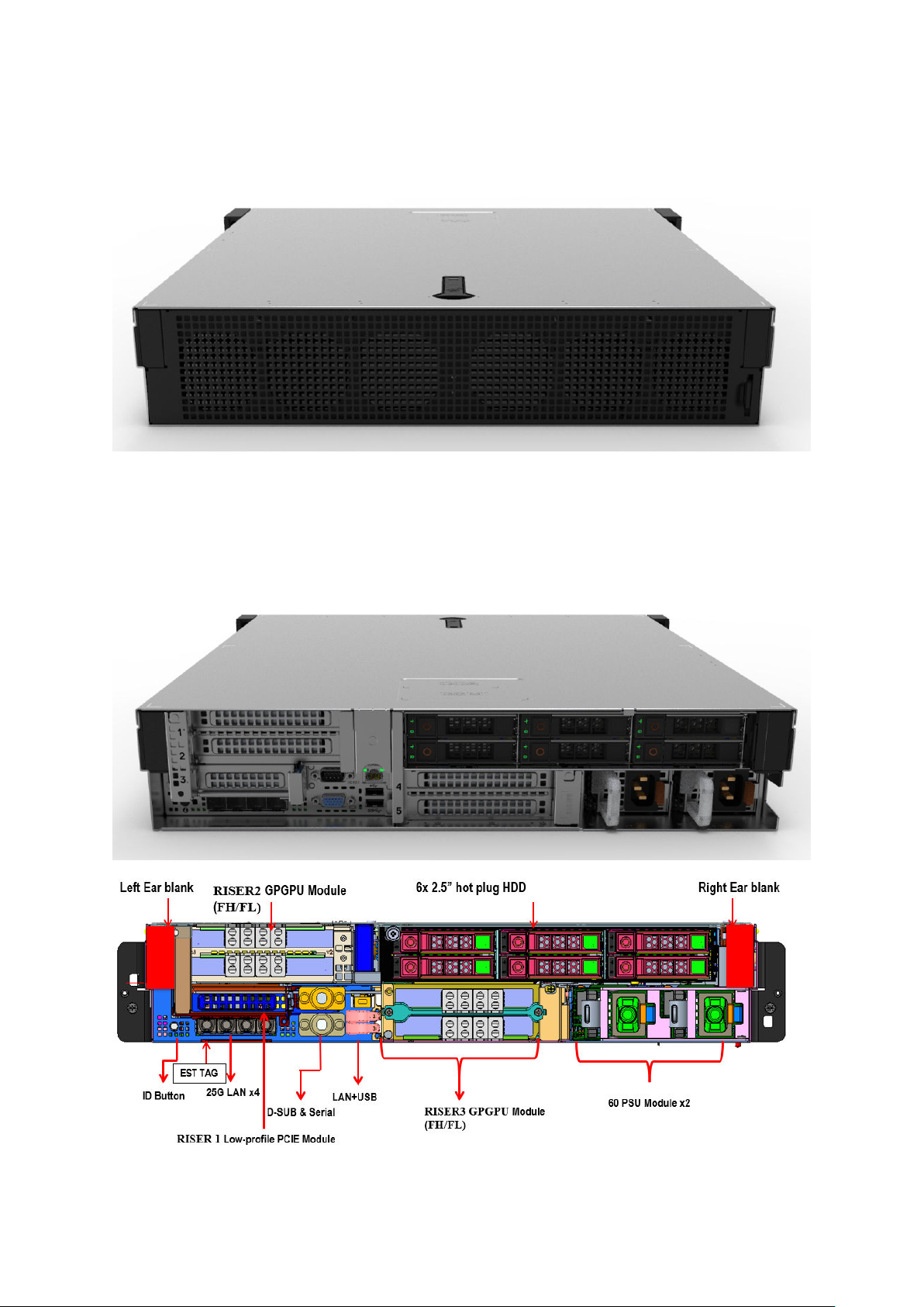
Inside the XR12 rear accessed chassis
Figure 18. XR12 Rear accessed chassis internal view (no bezel, no shroud)
22
Chassis views and features
Page 23

Figure 19. XR12 Rear accessed chassis internal exploded view
Quick Resource Locator (QRL)
There are two types of QRLs on the PowerEdge XR11 and XR12: a generic QRL and a QRL on the Express Service Tag (EST).
The generic QRL for XR11 and XR12 can be found on the System Information Labels (SILs), Getting Started Guide (GSG) and
Installation and Service Manuals. It leads to a webpage with links to product information such as Setup and Service videos,
iDRAC Manual, and other resources that apply to the platform.
The QRL on the EST for XR11 and XR12 is located on the information tag and is unique and specific to that service tag. It
contains the service tag number of the system. The label and the QRL code within it are printed on demand at the L10 factories.
The QRL on the EST also links to a webpage that shows the exact configuration as built for that customer, and the specific
warranty purchased. It is one click away from the same content of generic information that applies to XR11 and XR12 that is
available in the other QRL.
Chassis views and features
23
Page 24

Figure 20. Generic QRL for XR11 on SIL
Figure 21. Generic QRL for XR12 on SIL
Figure 22. QRL on EST
24
Chassis views and features
Page 25

Processor
Topics:
• Processor features
• Supported processors for XR11 and XR12
Processor features
The 3rd Generation Xeon Scalable Processors stack is the next generation data center processor offering with the latest
features, increased performance, and incremental memory options. This latest generation Xeon Scalable processor will support
usages from entry designs based on Intel Xeon Silver processors to advanced capabilities offered in new Intel Xeon Platinum
processor.
The following lists the features and functions included in the upcoming 3rd Generation Intel Xeon Scalable Processor offering :
● More, Faster I/O with PCI Express 4 and up to 64 lanes (per socket) at 16 GT/s
4
Supported processors for XR11 and XR12
The table below details the list of processors that will be offered at launch. This list is subject to change based on Intel Roadmap
and will be updated accordingly.
Table 3. Processor SKU stack
Proc
8351N 2.4 54 36 72 Turbo 2933 6TB Y 225WSupported Supported
6354 3 39 18 36 Turbo 3200 6TB Y 205WSupported Supported
6338
T
6338
N
6330
N
6326 2.9 24 16 32 Turbo 3200 6TB Y 185WSupported Supported
Clock
Speed
(GHz)
2.1 48 32 64 Turbo 3200 6TB Y 165WSupported Supported
2.2 48 32 64 Turbo 2666 6TB Y 185WSupported Supported
2.2 42 28 56 Turbo 2666 6TB Y 165WSupported Supported
Cache
(M)
Cores
Thread
s
Turbo
Memory
Speed
(MT/s)
Memory
Capacity
Intel
Mem
Enabled
TDP XR11 XR12
6314U 2.3 48 32 64 Turbo 3200 6TB Y 205WSupported Supported
6312U 2.4 36 24 48 Turbo 3200 6TB Y 185WSupported Supported
Processor 25
Page 26

Table 3. Processor SKU stack (continued)
Proc
5320
T
5318Y 2.1 36 24 48 Turbo 2933 6TB Y 165WSupported Supported
5318N 2.1 36 24 48 Turbo 2666 6TB Y 150WSupported Supported
5317 3 18 12 24 Turbo 2933 6TB Y 150WSupported Supported
5315Y 3.2 12 8 16 Turbo 2933 6TB Y 140WSupported Supported
4316 2.3 30 20 40 Turbo 2666 6TB N 150WSupported Supported
4314 2.4 24 16 32 Turbo 2666 6TB Y 135WSupported Supported
4310 2.1 18 12 24 Turbo 2666 6TB N 120WSupported Supported
4310T 2.3 15 10 20 Turbo 2666 6TB N 105WSupported Supported
Clock
Speed
(GHz)
2.3 30 20 40 Turbo 2933 6TB Y 150WSupported Supported
Cache
(M)
Cores
Thread
s
Turbo
Memory
Speed
(MT/s)
Memory
Capacity
Intel
Mem
Enabled
TDP XR11 XR12
4309
.
2.8 12 8 16 Turbo 2666 6TB N 105WSupported Supported
Y
26
Processor
Page 27

5
Memory subsystem
The PowerEdge XR11 and XR12 systems support up to 8 DIMMs, with up to 1024 GB of standard memory and speeds of up to
3200MT/s.
In addition, the PowerEdge XR11 and XR12 systems support Registered DIMMs (RDIMMs) and Load Reduced DIMMs
(LRDIMMs) which use a buffer to reduce memory loading and provide greater density, allowing for the maximum platform
memory capacity. Unbuffered DIMMs (UDIMMs) and 3DS DIMMs are not supported on both XR11 and XR12. The XR11 and XR12
systems support up to 128 GB of Intel Optane DC persistent memory 200 Series.
Topics:
• Supported memory
Supported memory
The table below lists the memory technologies supported by the platforms XR11 and XR12.
Table 4. Supported DDR4 memory technologies
Feature XR11 and XR12 (DDR4)
DIMM Type RDIMM
LRDIMM
Transfer Speed 3200 MT/s
Voltage 1.2V (DDR4)
The table below lists the supported DDR4 DIMMs for the platforms XR11 and XR12.
Table 5. Memory speed
DIMM Type DIMM Ranking DIMM Capacity DIMM Speed
(MT/s)
RDIMM 1R 8 GB 3200 8 1.2 V
RDIMM 2R 16 GB 3200 8 1.2 V
RDIMM 2R 32 GB 3200 8 1.2 V
RDIMM 2R 64 GB 3200 4 1.2 V
LRDIMM 4R 128 GB 3200 4 1.2 V
Data width DIMM Volts
Memory subsystem 27
Page 28

6
Storage
Topics:
• Supported drives
• Internal storage configuration matrix for XR11
• Internal storage configuration matrix for XR12
• External storage
Supported drives
The XR11 and XR12 will support several types of drives in these technologies and form factors: 2.5-inch SATA solid-state drives
(SSDs), 2.5-inch SAS SSDs and 2.5-inch NVME SSDs. For a list of the specific drives supported on this platform, please refer to
the Drive And Platform Matrix.
Table 6. Supported drive specifications for XR11 and XR12
Form Factor Type Speed Rotational Speed Capacities
2.5-inch SATA SSD 6 GB N/A 240 GB, 480 GB, 960
GB, 1.92 TB, 3.84 TB
2.5-inch SAS SSD 12 GB N/A 400 GB, 800 GB, 960
GB, 1.6 TB, 1.92 TB,
3.84 TB, 7.68 TB, 15.36
TB
2.5-inch NVMe — N/A 375 GB, 750 GB, 960
GB, 1 TB, 2 TB, 4 TB, 8
TB, 1.6 TB, 3.2 TB, 6.4
TB, 1.92 TB, 3.84 TB,
7.68 TB, 12.8 TB
NOTE: XR11 and XR12 will not support Pin 3 power disable for 12 GB SAS drives as is common in other server designs.
NOTE: XR11 and XR12 will not support NVMe drives with Riser 1A installed.
Internal storage configuration matrix for XR11
Table 7. Internal storage configuration matrix
Config
uration
Chassis
Orientatio
n
Base Configuration
Description
Backplane
Description
Storage
Controller(s
)
Controller
Form Factor
BOSS
Enabled
Riser
Configuration
1 Rear
Access
(NAF)
2 Rear
Access
(NAF)
28 Storage
ASSY, CHAS, NAF,
4HD, 3PCI, 1U, XR11
ASSY, CHAS, NAF,
4HD, 3PCI, 1U, XR11
x4 2.5 SATA
(only)
x4 2.5 SAS/
SATA
Onboard
SATA
HBA355i Adapter Y C0/1: R1B+R2+R3
Onboard SATA Y C0/1: R1B+R2+R3
Page 29

Table 7. Internal storage configuration matrix (continued)
Config
uration
3 Rear
4 Rear
5 Rear
6 Rear
7 Front
8 Front
9 Front
Chassis
Orientatio
n
Access
(NAF)
Access
(NAF)
Access
(NAF)
Access
(NAF)
Access
(RAF)
Access
(RAF)
Access
(RAF)
Base Configuration
Description
ASSY, CHAS, NAF,
4HD, 3PCI, 1U, XR11
ASSY, CHAS, NAF,
4HD, 3PCI, 1U, XR11
ASSY, CHAS, NAF,
4HD, 3PCI, 1U, XR11
ASSY, CHAS, NAF,
4HD, 3PCI, 1U, XR11
ASSY, CHAS, RAF,
4HD, 3PCI, 1U, XR11
ASSY, CHAS, RAF,
4HD, 3PCI, 1U, XR11
ASSY, CHAS, RAF,
4HD, 3PCI, 1U, XR11
Backplane
Description
x4 2.5 SAS/
SATA
x4 2.5 SAS/
SATA
x4 2.5 NVME
(only)
x4 2.5 NVME
(only)
x4 2.5 SATA
(only)
x4 2.5 SAS/
SATA
x4 2.5 SAS/
SATA
Storage
Controller(s
)
H755 Adapter Y C0/1: R1B+R2+R3
H345 Adapter Y C0/1: R1B+R2+R3
S150 Direct Attach
H755 Adapter Y C0/1: R1B+R2+R3
Onboard
SATA
HBA355i Adapter Y C0/1: R1B+R2+R3
H755 Adapter Y C0/1: R1B+R2+R3
Controller
Form Factor
(SL)
Onboard SATA Y C0/1: R1B+R2+R3
BOSS
Enabled
Y C0/1: R1B+R2+R3
Riser
Configuration
C2: R1A+R2+R3
10 Front
Access
(RAF)
11 Front
Access
(RAF)
12 Front
Access
(RAF)
For cable routing information on the different configurations, please refer to the cable matrix on this link: https://
www.delltechnologies.com/sales/en-us/auth/index.htm.
ASSY, CHAS, RAF,
4HD, 3PCI, 1U, XR11
ASSY, CHAS, RAF,
4HD, 3PCI, 1U, XR11
ASSY, CHAS, RAF,
4HD, 3PCI, 1U, XR11
x4 2.5 SAS/
SATA
x4 2.5 NVME
(only)
x4 2.5 NVME
(only)
H345 Adapter Y C0/1: R1B+R2+R3
S150 Direct Attach
(SL)
H755 Adapter Y C0/1: R1B+R2+R3
Y C0/1: R1B+R2+R3
Internal storage configuration matrix for XR12
Table 8. Internal storage configuration matrix
Configu
ration
1 Front
Chassis
Orientatio
n
Access
(RAF)
Base
Configuration
Description
ASSY, CHAS, RAF,
6HD, 3PCI, 2U, XR12
Backplane
Description
x6 2.5 SATA
(only)
Storage
Controller(s
)
Onboard
SATA
Controller
Form Factor
Onboard
SATA
BOSS
Enable
d
Y C0: R1B+R2A+R3A
Riser
Configuration
C1: R1B+R2B+R3B
C2: R1B+R2B+R3A
C3: R1A+R2A+R3A
C4: R1A+R2B+R3A
2 Front
Access
(RAF)
ASSY, CHAS, RAF,
6HD, 3PCI, 2U, XR12
x6 2.5 SAS/
SATA
HBA355i Adapter Y C0: R1B+R2A+R3A
C1: R1B+R2B+R3B
C2: R1B+R2B+R3A
Storage 29
Page 30

Table 8. Internal storage configuration matrix (continued)
Configu
ration
3 Front
4 Front
5 Front
6 Front
7 Rear
8 Rear
9 Rear
Chassis
Orientatio
n
Access
(RAF)
Access
(RAF)
Access
(RAF)
Access
(RAF)
Access
(NAF)
Access
(NAF)
Access
(NAF)
Base
Configuration
Description
ASSY, CHAS, RAF,
6HD, 3PCI, 2U, XR12
ASSY, CHAS, RAF,
6HD, 3PCI, 2U, XR12
ASSY, CHAS, RAF,
6HD, 3PCI, 2U, XR12
ASSY, CHAS, RAF,
6HD, 3PCI, 2U, XR12
ASSY, CHAS, NAF,
6HD, 3PCI, 2U, XR12
ASSY, CHAS, NAF,
6HD, 3PCI, 2U, XR12
ASSY, CHAS, NAF,
6HD, 3PCI, 2U, XR12
Backplane
Description
x6 2.5 SAS/
SATA
x6 2.5 SAS/
SATA
x4 2.5 NVME
+ 2.5 SATA
x6 2.5 NVME
(only)
x6 2.5 SATA
(only)
x6 2.5 SAS/
SATA
x6 2.5 SAS/
SATA
Storage
Controller(s
)
H755 Adapter Y C0: R1B+R2A+R3A
H345 Adapter Y C0: R1B+R2A+R3A
S150 +
Onboard
SATA
H755 Adapter Y C0: R1B+R2A+R3A
Onboard
SATA
HBA355i Adapter Y C0: R1B+R2A+R3A
H755 Adapter Y C0: R1B+R2A+R3A
Controller
Form Factor
Direct Attach
(SL) +
Onboard
SATA
Onboard
SATA
BOSS
Enable
d
Y C0: R1B+R2A+R3A
Y C0: R1B+R2A+R3A
Riser
Configuration
C1: R1B+R2B+R3B
C2: R1B+R2B+R3A
C1: R1B+R2B+R3B
C2: R1B+R2B+R3A
C1: R1B+R2B+R3B
C2: R1B+R2B+R3A
C1: R1B+R2B+R3B
C2: R1B+R2B+R3A
C1: R1B+R2B+R3B
C2: R1B+R2B+R3A
C1: R1B+R2B+R3B
C2: R1B+R2B+R3A
C1: R1B+R2B+R3B
C2: R1B+R2B+R3A
10 Rear
Access
(NAF)
11 Rear
Access
(NAF)
12 Rear
Access
(NAF)
For cable routing information on the different configurations, please refer to the cable matrix on this link: https://
www.delltechnologies.com/sales/en-us/auth/index.htm.
ASSY, CHAS, NAF,
6HD, 3PCI, 2U, XR12
ASSY, CHAS, NAF,
6HD, 3PCI, 2U, XR12
ASSY, CHAS, NAF,
6HD, 3PCI, 2U, XR12
x6 2.5 SAS/
SATA
x4 2.5 NVME
+ 2.5 SATA
x6 2.5 NVME
(only)
H345 Adapter Y C0: R1B+R2A+R3A
C1: R1B+R2B+R3B
C2: R1B+R2B+R3A
S150 +
Onboard
SATA
H755 Adapter Y C0: R1B+R2A+R3A
Direct Attach
(SL) +
Onboard
SATA
Y C0: R1B+R2A+R3A
C1: R1B+R2B+R3B
C2: R1B+R2B+R3A
C1: R1B+R2B+R3B
C2: R1B+R2B+R3A
External storage
The XR11 and XR12 supports the external storage device types listed in the table below.
Table 9. Supported external storage devices for XR11 and XR12
Device Type Description
External Tape Supports connection to external USB tape products
NAS/IDM appliance software Supports NAS software stack
JBOD Supports connection to 12 Gbps SAS ME484, MD1420 and MD1400
30 Storage
Page 31

Expansion cards and expansion card risers
NOTE: A system event entry is logged in the iDRAC Lifecycle Controller if an expansion card riser is not supported or
missing. It does not prevent your system from turning on. However, if a F1/F2 pause occurs with an error message,
see Troubleshooting expansion cards section in the Dell EMC PowerEdge Servers Troubleshooting Guide at www.dell.com/
poweredgemanuals.
Topics:
• Expansion cards and risers for the PowerEdge XR11 system
• Expansion cards and risers for the PowerEdge XR12 system
Expansion cards and risers for the PowerEdge XR11 system
This section provides information on different expansion cards and risers supported for the PowerEdge XR11 system.
7
Expansion card installation guidelines
Figure 23. Expansion card slot connectors
1. IO_Riser3 ( Riser 3 connector)
Expansion cards and expansion card risers 31
Page 32
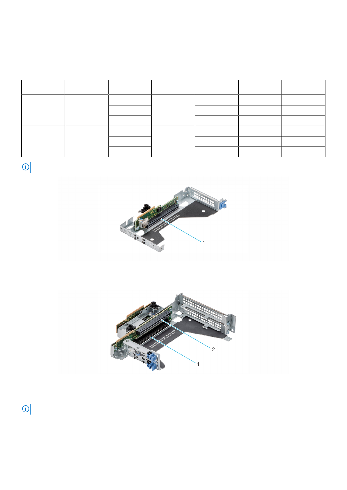
2. BOSS S1 card connector
3. IO_Riser2 ( Riser 2 connector)
4. IO_Riser1 (Riser 1 connector)
The following table describes the expansion card riser configurations:
Table 10. Expansion card riser configurations
Configurations Expansion card
risers
Config0. R1B+R2+R3
Rear Accessed
configuration
Config1. R1B+R2+R3
Front Accessed
configuration
NOTE: Riser 2 and 3 are combined in one expansion card riser module.
PCIe Slots Controlling
processor
1 Processor 1 Low profile Half length x8
2 Full Height Half length x16
3 Full Height Half length x16
1 Processor 1 Low profile Half length x8
2 Low profile Half length x16
3 Full Height Half length x16
Height Length Slot width
Figure 24. Riser 1
1. Slot 1, x8, LP-HL (Low Profile - Half Length)
Figure 25. Riser 2 and 3
1. Slot 2, x16, FH-HL (Full Height - Half Length)
2. Slot 3, x16, FH-HL (Full Height - Half Length)
NOTE: The expansion-card slots are not hot-swappable.
The following table provides guidelines for installing expansion cards to ensure proper cooling and mechanical fit. The expansion
cards with the highest priority should be installed first using the slot priority indicated. All the other expansion cards should be
installed in the card priority and slot priority order.
32
Expansion cards and expansion card risers
Page 33

Table 11. Configuration 0: R1B+R2+R3 for Rear Accessed configuration
Card type Slot priority Maximum number of cards
Internal PERC adapter (LP) 1 1
Dell External Adapter (FH) 3, 2 2
GPU (FH) 2, 3 2
Mellanox (NIC: 100Gb) (FH) 2, 3 2
Mellanox (NIC: 25Gb) (FH) 2, 3 2
Broadcom (NIC: 25Gb) (FH) 2, 3 2
Broadcom (NIC: 25Gb) (LP) 1 1
Broadcom (NIC: 10Gb) (FH) 2, 3 2
Broadcom (NIC: 10Gb) (LP) 1 1
Broadcom (NIC: 1Gb) (FH) 3, 2 2
Broadcom (NIC: 1Gb) (LP) 1 1
Intel (NIC: 25Gb) (FH) 2, 3 2
Intel (NIC: 25Gb) (LP) 1 1
Intel (NIC: 10Gb SFP+) (FH) 2 1
Intel (NIC: 10Gb SFP+) (FH) 2 1
Intel (NIC: 10Gb) (FH) (all others
including V2 of 4 x10 SFP+ and 2 x10
SFP+ cards)
Intel (NIC: 10Gb) (LP) 1 1
Intel (NIC: 1Gb) (FH) 3, 2 2
Intel (NIC: 1Gb) (LP) 1 1
Dell BOSS S1 card Module Integrated slot 1
2, 3 2
Table 12. Configuration 1: R1B+R2+R3 for Front Accessed configuration
Card type Slot priority Maximum number of cards
Internal PERC adapter (LP) 1 1
Dell External Adapter (FH) 3, 2 2
GPU (FH) 2, 3 2
Mellanox (NIC: 100Gb) (FH) 2, 3 2
Mellanox (NIC: 25Gb) (FH) 2, 3 2
Broadcom (NIC: 25Gb) (FH) 2, 3 2
Broadcom (NIC: 25Gb) (LP) 1 1
Broadcom (NIC: 10Gb) (FH) 2, 3 2
Broadcom (NIC: 10Gb) (LP) 1 1
Broadcom (NIC: 1Gb) (FH) 3, 2 2
Broadcom (NIC: 1Gb) (LP) 1 1
Intel (NIC: 25Gb) (FH) 2, 3 2
Intel (NIC: 25Gb) (LP) 1 1
Intel (NIC: 10Gb SFP+) (FH) 2 1
Expansion cards and expansion card risers 33
Page 34

Table 12. Configuration 1: R1B+R2+R3 for Front Accessed configuration (continued)
Card type Slot priority Maximum number of cards
Intel (NIC: 10Gb SFP+) (FH) 2 1
Intel (NIC: 10Gb) (FH) (all others
including V2 of 4 x10 SFP+ and 2 x10
SFP+ cards)
Intel (NIC: 10Gb) (LP) 1 1
Intel (NIC: 1Gb) (FH) 3, 2 2
Intel (NIC: 1Gb) (LP) 1 1
Dell BOSS S1 card Module Integrated slot 1
2, 3 2
Expansion cards and risers for the PowerEdge XR12 system
This section provides information on different expansion cards and risers supported for the PowerEdge XR12 system.
Expansion card installation guidelines
Figure 26. Expansion card slot connectors
1.
IO_Riser3 ( Riser 3 connector) 2. BOSS (M.2) card connector
3. IO_Riser2 ( Riser 2 connector) 4. IO_Riser1 (Riser 1 connector)
The following table describes the expansion card riser configurations:
34
Expansion cards and expansion card risers
Page 35

Configurations Expansion card
risers
PCIe Slots Controlling
processor
Height Length Slot width
Config0. R1B+R2A+R3A
Rear / Front
Accessed
configurations
Config1. R1B+R2B+R3B
Rear / Front
Accessed
configurations
Config2. R1B+R2B+R3A
Rear / Front
Accessed
configurations
3 Processor 1 Low profile Half length x8
2 Full Height Full length x16
4 Full Height Full length x16
3 Processor 1 Low profile Half length x8
1, 2 Full Height Full length x8+x8
4, 5 Full Height Full length x8+x8
3 Processor 1 Low profile Half length x8
1, 2 Full Height Full length x8+x8
4 Full Height Full length x16
Figure 27. Riser 1
1. Riser 1, slot 3, x8, LP-HL
Figure 28. Riser 2A
1. Riser 2, slot 2, x16, FH-FL
Expansion cards and expansion card risers
35
Page 36

Figure 29. Riser 3A
1. Riser 3, slot 4, x16, FH-FL
NOTE: The expansion-card slots are not hot-swappable.
The following table provides guidelines for installing expansion cards to ensure proper cooling and mechanical fit. The expansion
cards with the highest priority should be installed first using the slot priority indicated. All the other expansion cards should be
installed in the card priority and slot priority order.
Table 13. Configuration 0: R1B+R2A+R3A for Rear / Front Accessed configurations
Card type Slot priority Maximum number of cards
Internal PERC adapter (LP) 3 1
Dell External Adapter (FH) 2, 4 2
GPU (FH) 4, 2 2
Mellanox (NIC: 100Gb) (FH) 4, 2 2
Mellanox (NIC: 25Gb) (FH) 4, 2 2
Broadcom (NIC: 25Gb) (FH) 4, 2 2
Broadcom (NIC: 25Gb) (LP) 3 1
Broadcom (NIC: 10Gb) (FH) 4, 2 2
Broadcom (NIC: 10Gb) (LP) 3 1
Broadcom (NIC: 1Gb) (FH) 4, 2 2
Broadcom (NIC: 1Gb) (LP) 3 1
Intel (NIC: 25Gb) (FH) 4, 2 2
Intel (NIC: 25Gb) (LP) 3 1
Intel (NIC: 4x10Gb SFP+) (FH) 2 1
Intel (NIC: 2x10Gb SFP+) (FH) 2 1
Intel (NIC: 10Gb) (FH) (all others
including V2 of 4x10 and 2x10 SFP+
cards)
Intel (NIC: 10Gb) (LP) 3 1
Intel (NIC: 1Gb) (FH) 4, 2 2
Intel (NIC: 1Gb) (LP) 3 1
Dell BOSS S1 card Module Integrated slot 1
36 Expansion cards and expansion card risers
4, 2 2
Page 37

Table 14. Configuration 1: R1B+R2B+R3B Rear / Front Accessed configurations
Card type Slot priority Maximum number of cards
Internal PERC adapter (LP) 3 1
Dell External Adapter (FH) 1, 2, 4, 5 2
Broadcom (NIC: 25Gb) (FH) 4, 5, 2, 1 4
Broadcom (NIC: 25Gb) (LP) 3 1
Broadcom (NIC: 10Gb) (FH) 4, 5, 2, 1 4
Broadcom (NIC: 10Gb) (LP) 3 1
Broadcom (NIC: 1Gb) (FH) 4, 5, 2, 1 4
Broadcom (NIC: 1Gb) (LP) 3 1
Intel (NIC: 25Gb) (FH) 4, 5, 1, 2 4
Intel (NIC: 25Gb) (LP) 3 1
Intel (NIC: 4x10Gb SFP+) (FH) 1, 2 2
Intel (NIC: 2x10Gb SFP+) (FH) 1, 2 2
Intel (NIC: 10Gb) (FH) (all others
including V2 of 4x10 and 2x10 SFP+
cards)
Intel (NIC: 10Gb) (LP) 3 1
Intel (NIC: 1Gb) (FH) 4, 5, 1, 2 4
Intel (NIC: 1Gb) (LP) 3 1
Dell BOSS S1 card Module Integrated slot 1
4, 5, 1, 2 4
Table 15. Configuration 2: R1B+R2B+R3A for Rear / Front Accessed configuration
Card type Slot priority Maximum number of cards
Internal PERC adapter (LP) 3 1
Dell External Adapter (FH) 2, 1, 4 2
GPU (FH) 4 1
Mellanox (NIC: 100Gb) (FH) 4 1
Mellanox (NIC: 25Gb) (FH) 4 1
Broadcom (NIC: 25Gb) (FH) 4, 1, 2 3
Broadcom (NIC: 25Gb) (LP) 3 1
Broadcom (NIC: 10Gb) (FH) 4, 1, 2 3
Broadcom (NIC: 10Gb) (LP) 3 1
Broadcom (NIC: 1Gb) (FH) 4, 1, 2 3
Broadcom (NIC: 1Gb) (LP) 3 1
Intel (NIC: 25Gb) (FH) 4, 1, 2 3
Intel (NIC: 25Gb) (LP) 3 1
Intel (NIC: 4x10Gb SFP+) (FH) 1, 2 2
Intel (NIC: 2x10Gb SFP+) (FH) 1, 2 2
Expansion cards and expansion card risers 37
Page 38

Table 15. Configuration 2: R1B+R2B+R3A for Rear / Front Accessed configuration (continued)
Card type Slot priority Maximum number of cards
Intel (NIC: 10Gb) (FH) (all others
including V2 of 4x10 and 2x10 SFP+
cards)
Intel (NIC: 10Gb) (LP) 3 1
Intel (NIC: 1Gb) (FH) 4, 1, 2 3
Intel (NIC: 1Gb) (LP) 3 1 3 1
Dell BOSS S1 card Module Integrated slot 1
CAUTION: Do not install GPUs, network cards, or other PCIe devices on your system that are not validated
and tested by Dell. Damage caused by unauthorized and invalidated hardware installation will null and void the
system warranty.
WARNING: Consumer-Grade GPU should not be installed or used in the Enterprise Server products.
4, 1, 2 3
38 Expansion cards and expansion card risers
Page 39

Power, thermal, and acoustics
Topics:
• Power for XR11 and XR12
• Thermal for XR11 and XR12
• Acoustics
Power for XR11 and XR12
PowerEdge servers have an extensive collection of sensors that automatically track thermal activity, which helps regulate
temperature thereby reducing server noise and power consumption.
The table below lists the tools and technologies Dell offers to lower power consumption and increase energy efficiency.
Table 16. Power tools and technologies
Feature Description
8
Power Supply
Units (PSU)
portfolio
Tools for right
sizing
Industry
Compliance
Power
monitoring
accuracy
Power capping Use Dell's systems management to set the power cap limit for your systems to limit the output of a PSU
Systems
Management
Active power
management
Dell’s PSU portfolio includes intelligent features such as dynamically optimizing efficiency while maintaining
availability and redundancy. Find additional information in the Power Supply Units section.
Enterprise Infrastructure Planning Tool (EIPT) is a tool that can help you determine the most efficient
configuration possible. With Dell's EIPT, you can calculate the power consumption of your hardware, power
infrastructure, and storage at a given workload. Learn more at www.dell.com/calc.
Dell’s servers are compliant with all relevant industry certifications and guidelines, including 80 PLUS,
Climate Savers and ENERGY STAR.
PSU power monitoring improvements include:
● Dell’s power monitoring accuracy is currently 1%, whereas the industry standard is 5%
● More accurate reporting of power
● Better performance under a power cap
and reduce system power consumption. Dell is the first hardware vendor to leverage Intel Node Manager
for circuit-breaker fast capping.
iDRAC9 Datacenter provides server- level management that monitors, reports, and
controls power consumption at the processor, memory and system level.
Dell OpenManage Power Center delivers group power management at the rack, row, and
data center level for servers, power distribution units, and uninterruptible power supplies.
Intel Node Manager is an embedded technology that provides individual server-level power reporting
and power limiting functionality. Dell offers a complete power management solution comprised of Intel
Node Manager accessed through Dell iDRAC9 Datacenter and OpenManage Power Center that allows
policy-based management of power and thermals at the individual server, rack, and data center level. Hot
spare reduces power consumption of redundant power supplies. Thermal control off a speed optimizes the
thermal settings for your environment to reduce fan consumption and lower system power consumption.
Idle power enables Dell servers to run as efficiently when idle as when at full workload.
Fresh Air cooling Please refer to the section ASHRAE A3/A4/Rugged support restriction.
Rack
infrastructure
Dell offers some of the industry’s highest- efficiency power infrastructure solutions, including:
● Power distribution units (PDUs).
Power, thermal, and acoustics 39
Page 40

Table 16. Power tools and technologies (continued)
Feature Description
● Uninterruptible power supplies (UPSs).
● Energy Smart containment rack enclosures.
Find additional information at: https://www.delltechnologies.com/en-us/servers/power-and-cooling.htm.
Thermal for XR11 and XR12
PowerEdge servers have an extensive collection of sensors that automatically track thermal activity, which helps regulate
temperature thereby reducing server noise and power consumption.
Thermal management of the platform helps delivers high performance for the right amount of cooling to components at the
lowest fan speeds across a wide range of ambient temperatures from 10°C to 35°C (50°F to 86°F) and to extended ambient
temperature ranges (see Environmental Specifications). The benefits to you are lower fan power consumption (lower server
system power and data center power consumption) and greater acoustical versatility.
Acoustics
Acoustical design for XR11 and XR12
The acoustical design of the platform includes the following features:
Dell EMC PowerEdge delivers sound quality and smooth transient response in addition to sound power levels and sound pressure
levels oriented to deployment environments. Sound quality describes how disturbing or pleasing a person finds a sound, as
a function of a variety of psychoacoustical metrics and thresholds. Tone prominence is one such metric. Transient response
refers to how sound changes with time. Sound power level, sound pressure level, and loudness refer to amplitude of sound.
A reference for comparison to sound pressure levels and loudness for familiar noise sources is given in below table. A more
extensive description of Dell EMC PowerEdge acoustical design and metrics is available in the white paper, “Dell Enterprise
Acoustics”.
Table 17. Acoustical reference points and output comparisons
Value measured at your ears Equivalent familiar noise experience
LpA (dBA, re 20
µPa)
90 80 Loud concert
75 40 Data center, vacuum cleaner, voice must be elevated to be
60 10 Conversation levels
45 4 Whispering, open office layout, normal living room
35 2 Quiet office
30 1 Quiet library
20 0 Recording studio
Loudness, sones
heard
PowerEdge acoustics
Dell EMC PowerEdge XR11 and XR12 is a rack-mount server appropriate for general use space (Category 3) and unattended
data center environment (Category 5).
The table below shows the acoustical performance of the XR11 and XR12 for various configurations and acoustical categories.
40
Power, thermal, and acoustics
Page 41

Table 18. Acoustical performance of XR11 and XR12 NAF configurations
XR11 and XR12 NAF
Configuration
Acoustical Category Category 3 Category 3 Category 5
Processor 1x 10⁵ W 1x 150 W 1x 225 W
Memory 1x 8 GB RDIMM 2x 16 GB RDIMM 4x 32 GB RDIMM; 4x
Storage Front 1x 240 GB SSD 4x 480 GB SSD 4x 7.68 TB NVMe
Storage AUX2 None None BOSS-S1 2x 480 GB
PCIe Cards None 1x DP 25G 1x H755; 1x DP 25G;
PSU 1x 800 W 2x 800 W 2x 1400 W
Minimum Typical Maximum
128 GB Intel Optane
Persistent Memory
200 series DIMM
M.2
1x T4
Table 19. Acoustical performance of XR11 and XR12 RAF configurations
XR11 and XR12 RAF
Configuration
Acoustical Category Category 3 Category 3 Category 5
Processor 1x 10⁵ W 1x 150 W 1x 225 W
Minimum Typical Maximum
Memory 1x 8 GB RDIMM 2x 16 GB RDIMM 4x 32 GB LRDIMM; 4x
128 GB Intel Optane
Persistent Memory
200 series DIMM
Storage Front 1x 240 GB SSD 4x 480 GB SSD 4x 7.68 TB NVMe
Storage AUX2 None BOSS-S1 2x 480 GB M.2 BOSS-S1 2x 480 GB
M.2
PCIe Cards None 1x DP 25G 1x H755; 1x DP 25G;
1x T4
PSU 1x 1400 W 2x 1400 W 2x 1400 W
Power, thermal, and acoustics 41
Page 42

Rack, rails, and cable management
Key factors in selecting the proper rails include:
● Identifying the type of rack in which they will be installed
The spacing between the front and rear mounting flanges of the rack
●
● The type and location of any equipment mounted in the back of the rack such as power distribution units (PDUs), and the
overall depth of the rack
Reference the Dell EMC Enterprise Systems Rail Sizing and Rack Compatibility Matrix link below for the following information:
● Specific details about rail types and their functionalities
● Rail adjustability ranges for various rack mounting flange types
● Rail depth with and without cable management accessories
● Rack types supported for various rack mounting flange types
https://i.dell.com/sites/csdocuments/Business_solutions_engineering-Docs_Documents/en/rail-rack-matrix.pdf.
Topics:
• Rails information
• Cable Management Arm
• Strain Relief Bar
9
Rails information
The PowerEdge XR11 and XR12 only supports sliding rails. Due to the short depth of the XR11 and XR12, new sliding rails with
shorter minimum extension have been created.
NOTE: No other rails are compatible with the XR11 and XR12 system.
The sliding rails shown in below image Installing the system in Stab-in sliding rails allow the system to be fully extended out of
the rack for service and are available with the optional cable management arm (CMA) and optional strain relief bar (SRB). There
are 2 types of sliding rails available for the PowerEdge XR11 and XR12 as listed below:
● 2-post / 4-post rack mounting – traditional datacenter rack types with post-to-post depth range 18.5-inch – 29.5-inch [470
mm – 750 mm].
● Transit case mounting for mobility – The rugged MIL 910E performance is only certified in the Pelican DE2412-05/24/05
transit case.
The PowerEdge XR11 and XR12 sliding rails are stab-in style. A "stab-in" design means that the inner (chassis) rail members
must first be attached to the sides of the system and then inserted into the outer (cabinet) members installed in the rack. 2U
systems require a two-person lift.
Figure 30. Installing the system in stab-in sliding rails
42 Rack, rails, and cable management
Page 43

Dell PowerEdge XR11 and XR12 sliding rails overview:
● Support for tool-less installation in 19-inch EIA-310-E compliant square or unthreaded round hole racks including all
generations of Dell racks. Also supports tooled installation in threaded round hole racks.
● Supports Stab-in installation of the chassis to the rails.
● Support full extension of the system out of the rack to allow serviceability of key internal components.
● Supports for optional cable management arm (CMA) and strain relief bar (SRB).
Sliding rails in 2-post rack
The sliding rails for XR11 and XR12 provide support for 2-post racks with 19-inch EIA-310-E compliant square, round, or threaded
round mounting holes. Adapter brackets and screws (included in the rail kit) are necessary to mount the XR11 and XR12 into
2-post racks either in flush-mount or center-mount positions.
NOTE: Two-post racks are not supported in the rugged environment.
Figure 31. XR11 Mounted in sliding rails in 2-post center-mount configuration
Rack, rails, and cable management
43
Page 44

Figure 32. XR12 Mounted in sliding rails in 2-post center-mount configuration
Sliding rails in 4-post rack
The sliding rails for XR11 and XR12 provide tool-less support for 4-post racks with 19-inch EIA-310-E compliant square or
unthreaded round mounting holes including all generations of Dell racks when the post-to-post rack depth is between 18.5-inch
– 29.5-inch [470 mm – 750 mm]. There are additional screws included in the rail kit to tightly secure the rails to the 4-post rack
if desired.
Figure 33. XR11 and XR12 stab-in sliding rail mounting interface for 4-post round or square hole racks
44
Rack, rails, and cable management
Page 45

Figure 34. XR11 mounted in sliding rails with the CMA in 4-post rack
Figure 35. XR12 mounted in sliding rails with the CMA in 4-post rack
Rack, rails, and cable management
45
Page 46

Sliding rails in Pelican transit case
For transit cases, a specific type of rail has been designed. It is orderable from Dell and is compatible with the Pelican
DE2412-05/24/05 transit case. Dell only certifies XR11 and XR12 compliance for MIL 901E performance in this Pelican case.
Figure 36. XR11 and XR12 Transit case rails in Pelican case frame
Cable Management Arm
The optional cable management arm (CMA) for the XR11 and XR12 organizes and secures the cords and cables exiting the back
of the server and unfolds to allow the server to extend out of the rack without having to detach the cables. Some key features
of the CMA include:
● Large U-shaped baskets to support dense cable loads
● Open vent pattern for optimal airflow
● Can be mounted on either side by simply swinging the spring-loaded brackets from one side to the other
● Utilizes hook-and-loop straps rather than plastic tie wraps to eliminate the risk of cable damage during cycling
● Includes a low-profile fixed tray to both support and retain the CMA in its fully closed position
● Both the CMA and the tray mount without the use of tools via simple and intuitive snap-in designs
The CMA can be mounted to either side of the sliding rails without the use of tools or the need for conversion, but it is
recommended that it be mounted on the side opposite to the power supplies to allow easier access to the power supplies for
service or replacement.
46
Rack, rails, and cable management
Page 47

Figure 37. Sliding rails with optional CMA
Strain Relief Bar
The optional strain relief bar (SRB) for the XR11 and XR12 organizes and secures cables exiting the back of the server.
Figure 38. Sliding rails with optional SRB
● Tool-less attachment to rails
● Two depth positions to accommodate various cable loads and rack depths
● Supports cable loads and controls stresses on server connectors
● Cables can be segregated into discrete, purpose specific bundles
Rack, rails, and cable management
47
Page 48

10
Supported Operating Systems
The PowerEdge XR11 and XR12 systems support the following operating systems:
● Canonical® Ubuntu® Server LTS
Citrix® Hypervisor®
●
● Microsoft® Windows Server® with Hyper-V
● Red Hat® Enterprise Linux
● SUSE® Linux Enterprise server
● VMware® ESXi®
● RHEL Realtime
Links to specific OS versions and editions, certification matrices, Hardware Compatibility Lists (HCL) portal, and Hypervisor
support are available at Dell EMC Enterprise Operating Systems.
48 Supported Operating Systems
Page 49

11
Dell EMC OpenManage systems management
Figure 39. Dell EMC OpenManage Portfolio
Dell EMC delivers management solutions that help IT Administrators effectively deploy, update, monitor, and manage IT assets.
OpenManage solutions and tools enable you to quickly respond to problems by helping them to manage Dell EMC servers
effectively and efficiently; in physical, virtual, local, and remote environments, operating in-band, and out-of-band (agent-free).
The OpenManage portfolio includes innovative embedded management tools such as the integrated Dell Remote Access
Controller (iDRAC), Chassis Management Controller and Consoles like OpenManage Enterprise, OpenManage Power Manager
plug in, and tools like Repository Manager.
Dell EMC has developed comprehensive systems management solutions based on open standards and has integrated with
management consoles that can perform advanced management of Dell hardware. Dell EMC has connected or integrated the
advanced management capabilities of Dell hardware into offerings from the industry's top systems management vendors and
frameworks such as Ansible, thus making Dell EMC platforms easy to deploy, update, monitor, and manage.
The key tools for managing Dell EMC PowerEdge servers are iDRAC and the one-to-many OpenManage Enterprise console.
OpenManage Enterprise helps the system administrators in complete lifecycle management of multiple generations of
PowerEdge servers. Other tools such as Repository Manager, which enables simple yet comprehensive change management.
OpenManage tools integrate with systems management framework from other vendors such as VMware, Microsoft, Ansible, and
ServiceNow. This enables you to use the skills of the IT staff to efficiently manage Dell EMC PowerEdge servers.
Topics:
• Server and Chassis Managers
• Dell EMC consoles
• Automation Enablers
• Integration with third-party consoles
• Connections for third-party consoles
• Dell EMC Update Utilities
• Dell resources
Dell EMC OpenManage systems management 49
Page 50

Server and Chassis Managers
● Integrated Dell Remote Access Controller (iDRAC)
● iDRAC Service Module (iSM)
Dell EMC consoles
● Dell EMC OpenManage Enterprise
● Dell EMC Repository Manager (DRM)
● Dell EMC OpenManage Enterprise Power Manager plugin to OpenManage Enterprise
● Dell EMC OpenManage Mobile (OMM)
Automation Enablers
● OpenManage Ansible Modules
● iDRAC RESTful APIs (Redfish)
● Standards-based APIs (Python, PowerShell)
● RACADM Command Line Interface (CLI)
● GitHub Scripting Libraries
Integration with third-party consoles
● Dell EMC OpenManage Integrations with Microsoft System Center
● Dell EMC OpenManage Integration for VMware vCenter (OMIVV)
● Dell EMC OpenManage Ansible Modules
● Dell EMC OpenManage Integration with ServiceNow
Connections for third-party consoles
● Micro Focus and other HPE tools
● OpenManage Connection for IBM Tivoli
● OpenManage Plug-in for Nagios Core and XI
Dell EMC Update Utilities
● Dell System Update (DSU)
● Dell EMC Repository Manager (DRM)
● Dell EMC Update Packages (DUP)
● Dell EMC Server Update Utility (SUU)
● Dell EMC Platform Specific Bootable ISO (PSBI)
Dell resources
For additional information about white papers, videos, blogs, forums, technical material, tools, usage examples, and other
information, go to the OpenManage page at https://www.dell.com/openmanagemanuals or the following product pages:
50
Dell EMC OpenManage systems management
Page 51

Table 20. Dell resources
Resource Location
Integrated Dell Remote Access Controller (iDRAC) https://www.dell.com/idracmanuals
iDRAC Service Module (iSM) https://www.dell.com/support/kbdoc/000178050/
OpenManage Ansible Modules https://www.dell.com/support/kbdoc/000177308/
OpenManage Essentials (OME) https://www.dell.com/support/kbdoc/000175879/
OpenManage Mobile (OMM) https://www.dell.com/support/kbdoc/000176046
OpenManage Integration for VMware vCenter (OMIVV) https://www.dell.com/support/kbdoc/000176981/
OpenManage Integration for Microsoft System Center
(OMIMSSC)
Dell EMC Repository Manager (DRM) https://www.dell.com/support/kbdoc/000177083
Dell EMC System Update (DSU) https://www.dell.com/support/kbdoc/000130590
Dell EMC Platform Specific Bootable ISO (PSBI) Dell.com/support/article/sln296511
Dell EMC Chassis Management Controller (CMC) www.dell.com/support/article/sln311283
OpenManage Connections for Partner Consoles https://www.dell.com/support/kbdoc/000146912
OpenManage Enterprise Power Manager https://www.dell.com/support/kbdoc/000176254
OpenManage Integration with ServiceNow (OMISNOW) Dell.com/support/article/sln317784
NOTE: Features may vary by server. Please refer to the product page on https://www.dell.com/manuals for details.
https://www.dell.com/support/kbdoc/000147399
Dell EMC OpenManage systems management 51
Page 52
12
Dell Technologies Services
Dell Technologies Services include a wide, customizable range of service choices to simplify the assessment, design,
implementation, management and maintenance of IT environments and to help you transition from platform to platform.
Depending on your current business requirements and the level of service right for you, we provide factory, on-site, remote,
modular, and specialized services that fit your needs and budget. We'll help with a little or a lot—your choice—and provide
access to our global resources.
For more information, see DellEMC.com/Services.
Topics:
• Dell EMC ProDeploy Enterprise Suite
• Dell EMC Remote Consulting Services
• Dell EMC Data Migration Service
• Dell EMC ProSupport Enterprise Suite
• Dell EMC ProSupport Plus for Enterprise
• Dell EMC ProSupport for Enterprise
• Dell EMC ProSupport One for Data Center
• ProSupport for HPC
• Support Technologies
• Dell Technologies Education Services
• Dell Technologies Consulting Services
• Dell EMC Managed Services
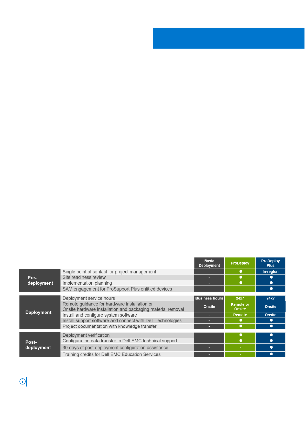
Dell EMC ProDeploy Enterprise Suite
ProDeploy Enterprise Suite gets your server out of the box and into optimized production—fast. Our elite deployment engineers
with broad and deep experience utilizing best-in-class processes along with our established global scale can help you around the
clock and around the globe. From simple to the most complex server installations and software integration, we take the guess
work and risk out of deploying your new server technology.
Figure 40. ProDeploy Enterprise Suite capabilities
NOTE: Hardware installation not applicable on selected software products.
52 Dell Technologies Services
Page 53

Dell EMC ProDeploy Plus
From beginning to end, ProDeploy Plus provides the skill and scale needed to successfully execute demanding deployments
in today's complex IT environments. Certified Dell EMC experts start with extensive environmental assessments and detailed
migration planning and recommendations. Software installation includes set up of most versions of Dell EMC SupportAssist and
OpenManage system management utilities. Post-deployment configuration assistance, testing, and product orientation services
are also available.
Dell EMC ProDeploy
ProDeploy provides full service installation and configuration of both server hardware and system software by certified
deployment engineers including set up of leading operating systems and hypervisors as well as most versions of Dell EMC
SupportAssist and OpenManage system management utilities. To prepare for the deployment, we conduct a site readiness
review and implementation planning exercise. System testing, validation, and full project documentation with knowledge transfer
complete the process.
Basic Deployment
Basic Deployment delivers worry-free professional installation by experienced technicians who know Dell EMC servers inside and
out.
Dell EMC Server Configuration Services
With Dell EMC Rack Integration and other Dell EMC PowerEdge Server Configuration Services, you save time by receiving your
systems racked, cabled, tested, and ready to integrate into the data center. Dell EMC staff pre-configure RAID, BIOS and iDRAC
settings, install system images, and even install third-party hardware and software.
For more information, see Server Configuration Services.
Dell EMC Residency Services
Residency Services helps customers transition to new capabilities quickly with the assistance of on-site or remote Dell EMC
experts whose priorities and time you control. Residency experts can provide post implementation management and knowledge
transfer related to a new technology acquisition or day-to-day operational management of the IT infrastructure.
Dell EMC Remote Consulting Services
When you are in the final stages of your PowerEdge server implementation, you can rely on Dell EMC Remote Consulting
Services and our certified technical experts to help you optimize your configuration with best practices for your software,
virtualization, server, storage, networking, and systems management.
Dell EMC Data Migration Service
Protect your business and data with our single point of contact to manage your data migration project. Your project manager will
work with our experienced team of experts to create a plan using industry-leading tools and proven processes based on global
best practices to migrate your existing files and data so your business system get up and running quickly and smoothly.
Dell EMC ProSupport Enterprise Suite
With the ProSupport Enterprise Suite, we help keep your IT systems running smoothly, so you can focus on running your
business. We will help maintain peak performance and availability of your most essential workloads. ProSupport Enterprise Suite
is a suite of support services that enable you to build the solution that is right for your organization.
Dell Technologies Services
53
Page 54

Choose support models based on how you use technology and where you want to allocate resources. From the desktop to the
data center, address everyday IT challenges, such as unplanned downtime, mission-critical needs, data and asset protection,
support planning, resource allocation, software application management and more. Optimize IT resources by choosing the right
support model.
Figure 41. Dell EMC ProSupport Enterprise Suite
Dell EMC ProSupport Plus for Enterprise
When you purchase your PowerEdge server, we recommend ProSupport Plus, our proactive and preventative support service
for your business-critical systems. ProSupport Plus provides you with all the benefits of ProSupport, plus the following:
● An assigned Services Account Manager who knows your business and your environment
● Immediate advanced troubleshooting from an engineer who understands your PowerEdge server
● Personalized, preventive recommendations based on analysis of support trends and best practices from across the Dell
Technologies infrastructure solutions customer base to reduce support issues and improve performance
● Predictive analysis for issue prevention and optimization enabled by SupportAssist
● Proactive monitoring, issue detection, notification, and automated case creation for accelerated issue resolution enabled by
SupportAssist
● On-demand reporting and analytics-based recommendations enabled by SupportAssist and TechDirect
Dell EMC ProSupport for Enterprise
Our ProSupport service offers highly trained experts around the clock and around the globe to address your IT needs. We help
minimize disruptions and maximize availability of PowerEdge server workloads with:
● 24x7 support through phone, chat and online
● Predictive, automated tools and innovative technology
● A central point of accountability for all hardware and software issues
● Collaborative 3rd party support
● Hypervisor, operating system and application support
● Consistent experience regardless of where you are located or what language you speak
● Optional onsite parts and labor response options including next business day or four-hour mission critical
NOTE: Subject to service offer country availability.
54 Dell Technologies Services
Page 55

Figure 42. Dell EMC Enterprise Support model
Dell EMC ProSupport One for Data Center
ProSupport One for Data Center offers flexible site-wide support for large and distributed data centers with more than
1,000 assets. This offering is built on standard ProSupport components that leverage our global scale but are tailored to
your company's needs. While not for everyone, this service option offers a truly unique solution for Dell Technologies largest
customers with the most complex environments.
● Team of assigned Services Account Managers with remote, on-site options
● Assigned ProSupport One technical and field engineers who are trained on your environment and configurations
● On-demand reporting and analytics-based recommendations enabled by SupportAssist and TechDirect
● Flexible on-site support and parts options that fit your operational model
● A tailored support plan and training for your operations staff
ProSupport for HPC
The ProSupport for HPC provides solution-aware support including:
● Access to senior HPC experts
● Advanced HPC cluster assistance: performance, interoperability & configuration
● Enhanced HPC solution level end-to-end support
● Remote pre-support engagement with HPC Specialists during ProDeploy implementation
Learn more at DellEMC.com/HPC-Services.
Dell Technologies Services
55
Page 56

Figure 43. ProSupport for HPC
Support Technologies
Powering your support experience with predictive, data-driven technologies.
Dell EMC SupportAssist
The best time to solve a problem is before it happens. The automated proactive and predictive technology SupportAssist helps
reduce steps and time to resolution, often detecting issues before they become a crisis. Benefits include:
● Value—SupportAssist is available to all customers at no additional charge
● Improve productivity—replace manual, high-effort routines with automated support
● Accelerate time to resolution—receive issue alerts, automatic case creation, and proactive contact from Dell EMC experts
● Gain insight and control—optimize enterprise devices with on-demand ProSupport Plus reporting in TechDirect, and get
predictive issue detection before the problem starts
NOTE: SupportAssist is included with all support plans, but features vary based on service level agreement.
Figure 44. SupportAssist model
Get started at Dell.com/SupportAssist
56
Dell Technologies Services
Page 57

Dell EMC TechDirect
Boost IT team productivity when supporting Dell EMC systems. With over 1.4 million self-dispatches processed each year,
TechDirect has proven its effectiveness as a support tool. You can:
● Self-dispatch replacement parts
● Request technical support
● Integrate APIs into your help desk
Or, access all your Dell EMC certification and authorization requirements. Train your staff on Dell EMC products, as TechDirect
allows you to:
● Download study guides
● Schedule certification and authorization exams
● View transcripts of completed courses and exams
Register at techdirect.dell.
Dell Technologies Education Services
Build the IT skills required to influence the transformational outcomes of the business. Enable talent and empower teams with
the right skills to lead and execute transformational strategy that drives competitive advantage. Leverage the training and
certification required for real transformation.
Dell Technologies Education Services offers PowerEdge server training and certifications designed to help you achieve more
from your hardware investment. The curriculum delivers the information and the practical, hands-on skills that you and your
team need to confidently install, configure, manage, and troubleshoot your Dell EMC servers. To learn more or register for a
class today, see LearnDell.com/Server.
Dell Technologies Consulting Services
Our expert consultants help you transform faster, and quickly achieve business outcomes for the high value workloads Dell EMC
PowerEdge systems can handle.
From strategy to full-scale implementation, Dell Technologies Consulting can help you determine how to execute your IT,
workforce, or application transformation.
We use prescriptive approaches and proven methodologies combined with Dell Technologies' portfolio and partner ecosystem
to help you achieve real business outcomes. From multi-cloud, applications, DevOps, and infrastructure transformations, to
business resiliency, data center modernization, analytics, workforce collaboration, and user experiences—we're here to help.
Dell EMC Managed Services
Reduce the cost, complexity, and risk of managing IT. Focus your resources on digital innovation and transformation while our
experts help optimize your IT operations and investment with managed services backed by guaranteed service levels.
Dell Technologies Services
57
Page 58

Appendix A. Additional specifications
Topics:
• Chassis dimensions
Chassis weight
•
• Video specifications
• USB ports
• Power Supply Units for XR11 and XR12
• Environmental Specifications for XR11 and XR12
Chassis dimensions
13
Figure 45. XR11 and XR12 Chassis dimensions for rear accessed (top) and front accessed (bottom)
58 Appendix A. Additional specifications
Page 59

Table 21. XR11 and XR12 Chassis dimensions
Dime
nsion
s
Xa 482.6 mm (19 inches) 482.6 mm (19 inches) 482.6 mm (19 inches) 482.6 mm (19 inches)
Xb 434 mm (17.08 inches) 434 mm (17.08 inches) 434 mm (17.08 inches) 434 mm (17.08 inches)
Y 42.8 mm (1.68 inches) 86.8 mm (3.41 inches) 42.8 mm (1.68 inches) 86.8 mm (3.41 inches)
Za 31 mm (1.22 inches)
Za
(bezel
)
Zb 400 mm (15.74 inches)
Zc 432 mm (17 inches)
For XR11 and XR12 Rear Accessed (NAF) orientations support racks with 48 mm spacing from rack post to inside surface of rack
door.
45 mm (1.77 inches)
XR11 XR12 XR11 XR12
without bezel
with bezel
Ear to rear wall
Ear to PSU handle
Rear Access (NAF) Front Access (RAF)
31 mm (1.22 inches)
without bezel
45 mm (1.77 inches)
with bezel
400 mm (15.74 inches)
Ear to rear wall
432 mm (17 inches)
Ear to PSU handle
63 mm (2.48 inches)
without bezel
N/A
400 mm (15.74 inches)
Ear to rear wall
N/A N/A
63 mm (2.48 inches)
without bezel
153 mm (6.02 inches)
400 mm (15.74 inches)
Ear to rear wall
with bezel
Appendix A. Additional specifications
59
Page 60

Chassis weight
Table 22. XR11 and XR12 Maximum chassis weight
Dimensions
Maximum weight
(with all drives/
SSDs/rails/
bezel)
XR11 XR12 XR11 XR12
13.8 kg 19.5 kg 13.6 kg 20.5 kg
Rear Access (NAF) Front Access (RAF)
Video specifications
The platform supports the following video resolution and refresh rates:
Table 23. Video resolution and refresh rate
Resolution Refresh Rate Freq. Pixel Clock DVO DisplayPort
1024 x 768 60 Hz 48.4 kHz 65.0 MHz Yes*
1280 x 800 60 Hz 49.7 kHz 83.5 MHz Yes*
1280 x 1024 60 Hz 64.0 kHz 108.0 MHz Yes*
1360 x 768 60 Hz 47.71 kHz 85.5 MHz Yes*
1440 x 900 60 Hz 55.9 kHz 106.5 MHz Yes*
1600 x 900 60 Hz 55.54 kHz 97.75 MHz Yes*
1600 x 1200 60 Hz 75.0 kHz 162.0 MHz Yes*
1680 x 1050 60 Hz 64.7 kHz 119.0 MHz Yes*
1920 x 1080 60 Hz (RB) 67.158 kHz 173.0 MHz No
1920 x 1200 60 Hz (RB) 74.556 kHz 193.25 MHz No
*DVO - DP is for investigation only, dependent on Nuvoton DVO capabilities to support up to 165 MHz. Rear Panel Performance
is TBD subject to final board design and losses to rear VGA connector.
*(RB) - Reduced Blanking for Digital Displays requiring less blank time. This was introduced for Signal Integrity improvements by
reducing Pixel Clock rates for VGA- Analog input devices.
USB ports
USB ports specifications for XR11
Table 24. PowerEdge XR11 USB ports specifications for Rear Accessed configuration
Front Rear Internal
USB port type No. of ports USB port type No. of ports USB port type No. of ports
USB 2.0compliant port
One USB 2.0-
compliant port
One Internal USB 3.0-
compliant port
One
60 Appendix A. Additional specifications
Page 61

Table 24. PowerEdge XR11 USB ports specifications for Rear Accessed configuration (continued)
Front Rear Internal
USB port type No. of ports USB port type No. of ports USB port type No. of ports
Micro-USB 2.0compliant port for
iDRAC Direct
One USB 3.0-
compliant port
One
Table 25. PowerEdge XR11 USB ports specifications for Front Accessed configuration
Front Internal
USB port type No. of ports USB port type No. of ports
USB 2.0-compliant port One Internal USB 3.0-compliant
USB 3.0-compliant port One
Micro-USB 2.0-compliant
port for iDRAC Direct
NOTE: Internal USB port is available on Riser 1B.
One
port
One
USB ports specifications for XR12
Table 26. PowerEdge XR12 USB ports specifications for Rear Accessed configuration
Front Rear Internal
USB port type No. of ports USB port type No. of ports USB port type No. of ports
USB 2.0compliant port
One USB 2.0-
compliant port
One Internal USB 3.0-
compliant port
One
Micro-USB 2.0compliant port for
iDRAC Direct
One USB 3.0-
compliant port
One
Table 27. PowerEdge XR12 USB ports specifications for Front Accessed configuration
Front Internal
USB port type No. of ports USB port type No. of ports
USB 2.0-compliant port Two Internal USB 3.0-compliant
USB 3.0-compliant port One
Micro-USB 2.0-compliant
port for iDRAC Direct
NOTE: Internal USB port is available on Riser 1B.
One
port
One
Power Supply Units for XR11 and XR12
Energy Smart power supplies have intelligent features, such as the ability to dynamically optimize efficiency while maintaining
availability and redundancy. Also featured are enhanced power-consumption reduction technologies, such as high-efficiency
power conversion, advanced thermal-management techniques, and embedded power-management features including highaccuracy power monitoring.
Appendix A. Additional specifications
61
Page 62

Supported power supply units
The table below shows the power supply unit options that are available for the PowerEdge XR11 and XR12.
Table 28. Power supply unit options
Wattage Frequency Voltage Class Heat dissipation
800 W (WRAC & MM
240V)
*1100 W -48 VDC N/A -48-60 Vdc/27A N/A 4266 BTU/hr
*1400 W (WRAC & MM
240V)
NOTE: 1100 W -48 VDC and 1400 W AC come in Reverse Airflow offerings (Reverse Airflow PSUs).
50/60Hz 100-240 Vac/ 9.2-4.7 A Platinum 3139 BTU/hr
N/A 240 Vdc/ 3.8 A N/A 3139 BTU/hr
50/60Hz 100-240 Vac/ 12-8 A Platinum 5459 BTU/hr
N/A 240 Vdc/ 6.6 A N/A 5459 BTU/hr
Table 29. PSUs highline and lowline ratings
800 W Platinum 1100 W -48 VDC 1400 W Platinum
Peak Power (Highline) 1360 W N/A 2380 W
Highline 800 W N/A 1400 W
Peak Power (Lowline) 1360 W N/A 1785 W
Lowline 800 W N/A 1050 W
Highline 240 VDC 800 W N/A 1400 W
Highline 200-380 VDC N/A N/A N/A
DC -48--60 V N/A 1100 W N/A
The PowerEdge XR11 and XR12 support up to 2 AC or DC power supplies with 1+1 redundancy, autosensing and auto-switching
capability.
If two PSUs are present during POST, a comparison is made between the wattage capacities of the PSUs. In the event that the
PSU wattages do not match, the larger of the two PSUs is enabled and there is also a PSU mismatch warning displayed in BIOS
and iDRAC.
If a second PSU is added at run-time, in order for that particular PSU to be enabled, the wattage capacity of the first PSU must
equal the second PSU. Otherwise, the PSU will be flagged as unmatched in iDRAC and the second PSU will not be enabled.
The PowerEdge XR11 and XR12 Rear Accessed chassis will only support normal airflow PSUs. Reverse airflow PSUs cannot be
installed in a Rear Accessed/NAF chassis due to a specific keying mechanism on the chassis and PSU. Similarly, reverse airflow
PSUs are only allowed in Front Accessed/RAF chassis. A normal airflow PSU cannot be installed in a Front Accessed/RAF
chassis due to the same mechanical restrictions (keying mechanism) outlined above.
Power supply efficiency for XR11 and XR12
Dell PSUs have achieved Platinum efficiency levels as shown in the table below.
Table 30. PSU efficiency levels
Efficiency targets by load
Form factor Output Class 10% 20% 50% 100%
Redundant
60 mm
62 Appendix A. Additional specifications
800 W AC Platinum Platinum 89.00% 93.00% 94.00% 91.50%
1100 W -48 Vdc Power
Supply efficiency at
(-48 Vdc)
N/A 85.00% 90.00% 92.00% 90.00%
Page 63

Table 30. PSU efficiency levels (continued)
Efficiency targets by load
Form factor Output Class 10% 20% 50% 100%
1400 W AC Platinum Platinum 89.00% 93.00% 94.00% 91.50%
Environmental Specifications for XR11 and XR12
The table below details the environmental specifications for the platform. For additional information about environmental
measurements for specific system configurations, see Product Safety, EMC and Environmental datasheets.
An important feature of having a broad menu of different categories is to allow the same platform model to have different
operational ranges depending on the MRD defined.
A list of range categories for different configurations shall be identified by thermal team as early in the project as possible. Post
release, it may be found in the Dell EMC PowerEdge XR11 and XR12 Installation and Service Manual.
The below table summarizes the ASHRAE temperature, humidity and de-rating requirements.
Table 31. Operational climatic range ASHRAE categories
ASHRAE A2 Allowable continuous operations
Temperature Ranges (For Altitude <900 meters or 2953 feet) 10 to 35°C (50 to 95°F) with no direct sunlight on the
equipment
Humidity Percent Ranges (Non-Condensing at all times) 8%RH with -12°C minimum dew point to 80%RH with 21°C
(69.8°F) maximum dew point
Operational Altitude De-Rating Maximum temperature is reduced by 1°C/300 meters
(33.8°F/984 feet) above 900 meters (2,953 feet)
ASHRAE A3 Allowable continuous operations
Temperature Ranges (For Altitude <900 meters or 2953 feet) 5 to 40°C (41 to 104°F) with no direct sunlight on the
platform
Humidity Percent Ranges (Non-Condensing at all times) 8%RH with -12°C minimum dew point to 85%RH with 24°C
(75.2°F) maximum dew point
Operational Altitude De-Rating Maximum temperature is reduced by 1°C/175 meters
(33.8°F/574 feet) above 900 meters (2,953 feet)
ASHRAE A4 Allowable continuous operations
Temperature Ranges (For Altitude <900 meters or 2953 feet) 5 to 45°C (41 to 113°F) with no direct sunlight on the
equipment
Humidity Percent Ranges (Non-Condensing at all times) 8%RH with -12°C minimum dew point to 90%RH with 24°C
(75.2°F) maximum dew point
Operational Altitude De-Rating Maximum temperature is reduced by 1°C/125 meters
(33.8°F/410 feet) above 900 meters (2,953 feet)
Rugged Allowable continuous operations
Temperature Ranges (For Altitude <900 meters or 2953 feet) -5 to 55°C (23 to 131°F) with no direct sunlight on the
equipment
Humidity Percent Ranges (Non-Condensing at all times) 8%RH with -12°C minimum dew point to 90%RH with 24°C
(75.2°F) maximum dew point
Operational Altitude De-Rating Maximum temperature is reduced by 1°C/80 meters
(33.8°F/262 feet) above 900 meters (2,953 feet)
The table below shows the requirements shared across all environmental categories.
Appendix A. Additional specifications
63
Page 64

Table 32. Shared requirements
Allowable continuous operations
Maximum Temperature Gradient (applies to both operation
and non-operation)
Non-Operational Temperature Limits -40 to 65°C (-40 to 149°F)
Non-Operational Humidity Limits (Non-Condensing at all
times)
Maximum Non-Operational Altitude 12,000 meters (39,370 feet)
Maximum Operational Altitude 3,048 meters (10,000 feet)
20°C in an hour* (36°F in an hour) and 5°C in 15 minutes
(9°F in 15 minutes),
5°C in an hour* (9°F in an hour) for tape hardware
5% to 95%RH with 27°C (80.6°F) maximum dew point.
Table 33. Maximum vibration specifications
Maximum vibration Specifications
Operating MIL-STD-810H, Method 514.8, 1.04 Grms, 2-500Hz, Random
Vibration, Figure 514.8D-11
Storage
For XR11:
● MIL-STD-810H, Method 514.8, Category 4, Figure
514.8C-2, 10-500 Hz, 60 minutes/axis
● MIL-STD-810H, Method 514.8, Category 24, Figure
514.8E-1, 20-2000Hz, 60 minutes/axis
For XR12:
● MIL-STD-810H, Method 514.8, Category 4, Figure
514.8C-2, 5-500 Hz, 60 minutes/axis
● MIL-STD-810H, Method 514.8, Category 24, Figure
514.8E-1, 20-2000Hz, 60 minutes/axis
Table 34. Maximum shock specifications
Maximum shock Specifications
Operating
Operating (Navy) MIL-STD-901E, Grade A, Class 2, Type A, in approved military
Storage
MIL-STD-810H, Method 516.8, Procedure I, 11ms, 20G
MIL-STD-810H, Method 516.8, Procedure I, 11ms, 40G (SSD)
transit case
MIL-STD-810H, Method 516.8, Procedures I, 11 ms, 40G (SSD)
MIL-STD-810H, Method 516.8, Procedures I, 11 ms, 40G
ASHRAE A3/A4/Rugged support restriction for XR11 and XR12
Thermal Restrictions for ASHRAE A3 for Rear Accessed configuration
● Do not perform a cold startup below 5°C
● Processor TDP greater than 150 W are not supported
● 128 GB or greater capacity DIMMs and DCPMM are not supported
● Non-Dell qualified peripheral cards are not supported
● GPU is not supported
● PCIe SSDs are not supported
64
Appendix A. Additional specifications
Page 65

● BOSS M.2 is not supported
● High temperature spec 85°C active optics cables are required
● PERC with battery is not supported
● NVMe drives are not supported
● CX-6 100GB NIC card is not supported (XR11)
● SAS SSD is not supported (XR11)
Thermal Restrictions for ASHRAE A4 for Rear Accessed configuration
● Do not perform a cold startup below 5°C
● Processor TDP greater than 150 W are not supported
● 128 GB or greater capacity DIMMs and DCPMM are not supported
● Non-Dell qualified peripheral cards are not supported
● GPU is not supported
● PCIe SSDs are not supported
● BOSS M.2 is not supported
● High temperature spec 85°C active optics cables are required
● PERC with battery is not supported
● NVMe drives are not supported
● CX-6 100GB NIC card is not supported (XR11)
● SAS SSD is not supported (XR11)
Thermal Restrictions for Rugged Rear Accessed configuration
● Do not perform a cold startup below 5°C
● Processor TDP greater than 150 W are not supported
● 128 GB or greater capacity DIMMs and DCPMM are not supported
● Two PSUs are required in redundant mode. System performance may be reduced in the event of a PSU failure
● Non-Dell qualified peripheral cards are not supported
● GPU is not supported
● PCIe SSDs are not supported
● BOSS M.2 is not supported
● High temperature spec 85°C active optics cables are required
● PERC with battery is not supported
● NVMe drives are not supported
● CX-6 100GB NIC card is not supported (XR11)
● SAS SSD is not supported (XR11)
Thermal Restrictions for ASHRAE A3 for Front Accessed configuration
● Do not perform a cold startup below 5°C
● Processor TDP greater than 150 W are not supported
● 128 GB or greater capacity DIMMs and DCPMM are not supported
● Non-Dell qualified peripheral cards are not supported
● GPU is not supported
● PCIe SSDs are not supported
● BOSS M.2 greater than 480 GB is not supported
● High temperature spec 85°C active optics cables are required
● NVMe drives are not supported
● SAS SSD is not supported (XR11)
Thermal Restrictions for ASHRAE A4 for Front Accessed configuration
Thermal Restrictions for ASHRAE A4 for Front Accessed configuration
Appendix A. Additional specifications
65
Page 66

● Do not perform a cold startup below 5°C
● Processor TDP greater than 150 W are not supported
● 128 GB or greater capacity DIMMs and DCPMM are not supported
● Non-Dell qualified peripheral cards are not supported
● GPU is not supported
● PCIe SSDs are not supported
● BOSS M.2 greater than 480 GB is not supported
● NVMe drives are not supported
● SAS SSD is not supported (XR11)
Thermal Restrictions for Rugged Front Accessed configuration
● Do not perform a cold startup below 5°C
● Processor TDP greater than 150 W are not supported
● 128 GB or greater capacity DIMMs and DCPMM are not supported
● Non-Dell qualified peripheral cards are not supported
● GPU is not supported
● PCIe SSDs are not supported
● BOSS M.2 is not supported
● PERC with battery is not supported
● NVMe drives are not supported
● SAS SSD is not supported (XR11)
Thermal restrictions
The XR11 and XR12 supports all standard configurations for continuous operation from 10°C to 35°C to meet ASHRAE standard
A2. Additionally, the XR11 and XR12 will support custom configurations in rugged environment temperatures up to 55°C.
Refer to the Environmental Specifications for information on ASHRAE temperature and humidity standards and any applicable
configuration restrictions. For information on rugged specifications, please refer to Rugged Certifications and Specifications
section. All configurations supported at the thermal limit of 55°C are subject to restrictions.
Table 35. Thermal restrictions for XR11 rear accessed chassis
Dell EMC PowerEdge Server
Extended Ambient 40°C Operating
Support (ASHRAE A3 compliant)
● Processor TDP greater than 150 W
are not supported
● 128 GB or greater capacity DIMMs
are not supported
● Intel PMem memory not supported
● NVMe or PCIeSSD not supported
● SAS SSD not supported
● BOSS 1.0 not supported
● GPU not supported
● PERC with battery not supported
● 100 GB NIC card not supported
● Non-Dell qualified peripheral cards
are not supported
● 85°C spec active optic cables are
required
Dell EMC PowerEdge Server
Extended Ambient 45°C Operating
Support (ASHRAE A4 compliant)
● Processor TDP greater than 150 W
are not supported
● 128 GB or greater capacity DIMMs
are not supported
● Intel PMem memory not supported
● NVMe or PCIeSSD not supported
● SAS SSD not supported
● BOSS 1.0 not supported
● GPU not supported
● PERC with battery not supported
● 100 GB NIC card not supported
● Non-Dell qualified peripheral cards
are not supported
● 85°C spec active optic cables are
required
Rugged Environment Extended
Ambient 55°C Operating Support
● Processor TDP greater than 150 W
are not supported
● 128 GB or greater capacity DIMMs
are not supported
● Intel PMem memory not supported
● NVMe or PCIeSSD not supported
● SAS SSD not supported
● BOSS 1.0 not supported
● GPU not supported
● PERC with battery not supported
● 100 GB NIC card not supported
● Non-Dell qualified peripheral cards
are not supported
● 85°C spec active optic cables are
required
● Two PSUs are required in redundant
mode. System performance may be
reduced in the event of a PSU failure
66 Appendix A. Additional specifications
Page 67

Table 36. Thermal restrictions for XR11 front accessed chassis
Dell EMC PowerEdge Server
Extended Ambient 40°C Operating
Support (ASHRAE A3 compliant)
● Processor TDP greater than 150 W
are not supported
● 128 GB or greater capacity DIMMs
are not supported
● Intel PMem memory not supported
● NVMe or PCIeSSD not supported
● SAS SSD not supported
● GPU not supported
● Non-Dell qualified peripheral cards
are not supported
Dell EMC PowerEdge Server
Extended Ambient 45°C Operating
Support (ASHRAE A4 compliant)
● Processor TDP greater than 150 W
are not supported
● 128 GB or greater capacity DIMMs
are not supported
● Intel PMem memory not supported
● NVMe or PCIeSSD not supported
● SAS SSD not supported
● GPU not supported
● Non-Dell qualified peripheral cards
are not supported
Table 37. Thermal restrictions for XR12 rear accessed chassis
Dell EMC PowerEdge Server
Extended Ambient 40°C Operating
Support (ASHRAE A3 compliant)
● Processor TDP greater than 150 W
are not supported
● 128 GB or greater capacity DIMMs
are not supported
● Intel PMem memory not supported
● NVMe or PCIeSSD not supported
● BOSS 1.0 not supported
● GPU not supported
● PERC with battery not supported
● Non-Dell qualified peripheral cards
are not supported
● 85°C spec active optic cables are
required
Dell EMC PowerEdge Server
Extended Ambient 45°C Operating
Support (ASHRAE A4 compliant)
● Processor TDP greater than 150 W
are not supported
● 128 GB or greater capacity DIMMs
are not supported
● Intel PMem memory not supported
● NVMe or PCIeSSD not supported
● BOSS 1.0 not supported
● GPU not supported
● PERC with battery not supported
● Non-Dell qualified peripheral cards
are not supported
● 85°C spec active optic cables are
required
Rugged Environment Extended
Ambient 55°C Operating Support
● Processor TDP greater than 150 W
are not supported
● 128 GB or greater capacity DIMMs
are not supported
● Intel PMem memory not supported
● NVMe or PCIeSSD not supported
● SAS SSD not supported
● GPU not supported
● PERC with battery not supported
● Non-Dell qualified peripheral cards
are not supported
Rugged Environment Extended
Ambient 55°C Operating Support
● Processor TDP greater than 150 W
are not supported
● 128 GB or greater capacity DIMMs
are not supported
● Intel PMem memory not supported
● NVMe or PCIeSSD not supported
● BOSS 1.0 not supported
● GPU not supported
● PERC with battery not supported
● Non-Dell qualified peripheral cards
are not supported
● 85°C spec active optic cables are
required
● Two PSUs are required in redundant
mode. System performance may be
reduced in the event of a PSU failure
Table 38. Thermal restrictions for XR12 front accessed chassis
Dell EMC PowerEdge Server
Extended Ambient 40°C Operating
Support (ASHRAE A3 compliant)
● Processor TDP greater than 150 W
are not supported
● 128 GB or greater capacity DIMMs
are not supported
● Intel PMem memory not supported
● NVMe or PCIeSSD not supported
● GPU not supported
● Non-Dell qualified peripheral cards
are not supported
Other Restrictions for XR11 and XR12:
● Do not perform a cold startup below 5°C
● DIMM blanks are required on empty slots
● HDD blanks are required on empty slots
● PCIe blank is require on empty slot1 for XR11 and empty slot3 for XR12
Dell EMC PowerEdge Server
Extended Ambient 45°C Operating
Support (ASHRAE A4 compliant)
● Processor TDP greater than 150 W
are not supported
● 128 GB or greater capacity DIMMs
are not supported
● Intel PMem memory not supported
● NVMe or PCIeSSD not supported
● GPU not supported
● Non-Dell qualified peripheral cards
are not supported
Rugged Environment Extended
Ambient 55°C Operating Support
● Processor TDP greater than 150 W
are not supported
● 128 GB or greater capacity DIMMs
are not supported
● Intel PMem memory not supported
● NVMe or PCIeSSD not supported
● GPU not supported
● PERC with battery not supported
● Non-Dell qualified peripheral cards
are not supported
Appendix A. Additional specifications
67
Page 68

● High temp spec (85°C) active optics cables are required for Rear Accessed Chassis at ambient higher than 35°C
68 Appendix A. Additional specifications
Page 69

Appendix B. Standards compliance
The system conforms to the following industry standards.
Table 39. Industry standard documents
Standard URL for information and specifications
14
ACPIAdvance Configuration and Power Interface
Specification, v2.0c
Ethernet IEEE 802.3-2005 https://standards.ieee.org/
HDGHardware Design Guide Version 3.0 for Microsoft
Windows Server
IPMI Intelligent Platform Management Interface, v2.0 intel.com/design/servers/ipmi
DDR4 Memory DDR4 SDRAM Specification jedec.org/standards-documents/docs/jesd79-4.pdf
PCI Express PCI Express Base Specification Rev. 2.0 and 3.0 pcisig.com/specifications/pciexpress
PMBus Power System Management Protocol Specification,
v1.2
SAS Serial Attached SCSI, v1.1 http://www.t10.org/
SATA Serial ATA Rev. 2.6; SATA II, SATA 1.0a Extensions,
Rev. 1.2
SMBIOS System Management BIOS Reference Specification,
v2.7
TPM Trusted Platform Module Specification, v1.2 and v2.0 trustedcomputinggroup.org
UEFI Unified Extensible Firmware Interface Specification, v2.1 uefi.org/specifications
USB Universal Serial Bus Specification, Rev. 2.0 usb.org/developers/docs
https://uefi.org/specsandtesttools
microsoft.com/whdc/system/platform/pcdesign/desguide/
serverdg.mspx
http://pmbus.org/Assets/PDFS/Public/
PMBus_Specification_Part_I_Rev_1-1_20070205.pdf
sata-io.org
dmtf.org/standards/smbios
Appendix B. Standards compliance 69
Page 70

Appendix C Additional resources
Table 40. Additional resources
Resource Description of contents Location
15
Installation and Service Manual
Getting Started Guide
Rack Installation Guide This document ships with the rack kits, and provides
System Information Label The system information label documents the system board
Quick Resource Locator (QRL) This code on the chassis can be scanned by a phone
This manual, available in PDF format, provides the following
information:
● Chassis features
● System Setup program
● System indicator codes
● System BIOS
● Remove and replace procedures
● Diagnostics
● Jumpers and connectors
This guide ships with the system, and is also available in PDF
format. This guide provides the following information:
● Initial setup steps
instructions for installing a server in a rack.
layout and system jumper settings. Text is minimized due
to space limitations and translation considerations. The label
size is standardized across platforms.
application to access additional information and resources for
the server, including videos, reference materials, service tag
information, and Dell EMC contact information.
Dell.com/Support/Manuals
Dell.com/Support/Manuals
Dell.com/Support/Manuals
Inside the system chassis
cover
Inside the system chassis
cover
Energy Smart Solution Advisor
(ESSA)
The Dell EMC online ESSA enables easier and more
meaningful estimates to help you determine the most
efficient configuration possible. Use ESSA to calculate the
power consumption of your hardware, power infrastructure,
and storage.
Dell.com/calc
70 Appendix C Additional resources
 Loading...