

Page 1

XPS 27
Owner’s Manual
Computer model: XPS 2720
Regulatory model: W06C
Regulatory type: W06C002
Page 2

Notes, Cautions, and Warnings
NOTE: A NOTE indicates important information that helps you make better
use of your computer.
CAUTION: A CAUTION indicates potential damage to hardware or loss of
data if instructions are not followed.
WARNING: A WARNING indicates a potential for property damage,
personal injury, or death.
____________________
© 2013 Dell Inc.
Trademarks used in this text: Dell™, the DELL logo, and XPS™ are trademarks of Dell Inc.;
Microsoft
Corporation in the United States and/or other countries; Blu-ray Disc™ is a trademark owned
by the Blu-ray Disc Association (BDA) and licensed for use on discs and players;
Bluetooth
license; Intel
and/or other countries.
2013 - 04 Rev. A00
®
and Windows
®
is a registered trademark owned by Bluetooth SIG, Inc. and is used by Dell under
®
and Intel SpeedStep® are registered trademarks of Intel Corporation in the U.S.
®
are either trademarks or registered trademarks of Microsoft
Page 3

Contents
1 Before You Begin . . . . . . . . . . . . . . . . . . . . . . . 11
Turn Off Your Computer and Connected Devices . . 11
Safety Instructions
Recommended Tools
2 After Working Inside Your Computer. . . . . . . 13
. . . . . . . . . . . . . . . . . . . . . . . 11
. . . . . . . . . . . . . . . . . . . . . 12
3 Technical Overview
Inside View of Your Computer . . . . . . . . . . . . . . . 14
System-Board Components
. . . . . . . . . . . . . . . . . . . . . 14
. . . . . . . . . . . . . . . . 15
4 Removing the Back Cover. . . . . . . . . . . . . . . . 17
Procedure . . . . . . . . . . . . . . . . . . . . . . . . . . . . 17
5 Replacing the Back Cover . . . . . . . . . . . . . . . . 18
Procedure . . . . . . . . . . . . . . . . . . . . . . . . . . . . 18
6 Removing the Trim Cover . . . . . . . . . . . . . . . . 19
Prerequisites. . . . . . . . . . . . . . . . . . . . . . . . . . . 19
Procedure
. . . . . . . . . . . . . . . . . . . . . . . . . . . . 19
7 Replacing the Trim Cover . . . . . . . . . . . . . . . . 20
Procedure . . . . . . . . . . . . . . . . . . . . . . . . . . . . 20
Postrequisites
. . . . . . . . . . . . . . . . . . . . . . . . . . 20
8 Removing the Stand . . . . . . . . . . . . . . . . . . . . 21
Prerequisites. . . . . . . . . . . . . . . . . . . . . . . . . . . 21
Procedure
. . . . . . . . . . . . . . . . . . . . . . . . . . . . 21
9 Replacing the Stand. . . . . . . . . . . . . . . . . . . . . 22
Procedure . . . . . . . . . . . . . . . . . . . . . . . . . . . . 22
Postrequisites
. . . . . . . . . . . . . . . . . . . . . . . . . . 22
Contents | 3
Page 4

10 Removing the Converter Board . . . . . . . . . . . 23
Prerequisites. . . . . . . . . . . . . . . . . . . . . . . . . . . 23
Procedure
. . . . . . . . . . . . . . . . . . . . . . . . . . . . 23
11 Replacing the Converter Board . . . . . . . . . . . 24
Procedure . . . . . . . . . . . . . . . . . . . . . . . . . . . . 24
Postrequisites
. . . . . . . . . . . . . . . . . . . . . . . . . . 24
12 Removing the Optical Drive . . . . . . . . . . . . . . 25
Prerequisites. . . . . . . . . . . . . . . . . . . . . . . . . . . 25
Procedure
. . . . . . . . . . . . . . . . . . . . . . . . . . . . 25
13 Replacing the Optical Drive . . . . . . . . . . . . . . 27
Procedure . . . . . . . . . . . . . . . . . . . . . . . . . . . . 27
Postrequisites
. . . . . . . . . . . . . . . . . . . . . . . . . . 27
14 Removing the Memory Module(s) . . . . . . . . . 28
Prerequisites. . . . . . . . . . . . . . . . . . . . . . . . . . . 28
Procedure
. . . . . . . . . . . . . . . . . . . . . . . . . . . . 28
15 Replacing the Memory Module(s). . . . . . . . . . 30
Procedure . . . . . . . . . . . . . . . . . . . . . . . . . . . . 30
Postrequisites
. . . . . . . . . . . . . . . . . . . . . . . . . . 30
16 Removing the System-Board Shield. . . . . . . . 31
Prerequisites. . . . . . . . . . . . . . . . . . . . . . . . . . . 31
Procedure
. . . . . . . . . . . . . . . . . . . . . . . . . . . . 31
17 Replacing the System-Board Shield . . . . . . . . 32
Procedure . . . . . . . . . . . . . . . . . . . . . . . . . . . . 32
Postrequisites
. . . . . . . . . . . . . . . . . . . . . . . . . . 32
18 Removing the Power-Supply Fan . . . . . . . . . . 33
Prerequisites. . . . . . . . . . . . . . . . . . . . . . . . . . . 33
Procedure
. . . . . . . . . . . . . . . . . . . . . . . . . . . . 33
19 Replacing the Power-Supply Fan . . . . . . . . . . 34
Procedure . . . . . . . . . . . . . . . . . . . . . . . . . . . . 34
Postrequisites
4 | Contents
. . . . . . . . . . . . . . . . . . . . . . . . . . 34
Page 5

20 Removing the Hard Drive . . . . . . . . . . . . . . . . 35
Prerequisites. . . . . . . . . . . . . . . . . . . . . . . . . . . 35
Procedure . . . . . . . . . . . . . . . . . . . . . . . . . . . . 35
21 Replacing the Hard Drive . . . . . . . . . . . . . . . . 37
Procedure . . . . . . . . . . . . . . . . . . . . . . . . . . . . 37
Postrequisites . . . . . . . . . . . . . . . . . . . . . . . . . . 37
22 Removing the Hard-Drive Cage . . . . . . . . . . . 38
Prerequisites. . . . . . . . . . . . . . . . . . . . . . . . . . . 38
Procedure . . . . . . . . . . . . . . . . . . . . . . . . . . . . 38
23 Replacing the Hard-Drive Cage . . . . . . . . . . . 39
Procedure . . . . . . . . . . . . . . . . . . . . . . . . . . . . 39
Postrequisites . . . . . . . . . . . . . . . . . . . . . . . . . . 39
24 Removing the I/O Panel . . . . . . . . . . . . . . . . . 40
Prerequisites. . . . . . . . . . . . . . . . . . . . . . . . . . . 40
Procedure . . . . . . . . . . . . . . . . . . . . . . . . . . . . 40
25 Replacing the I/O Panel. . . . . . . . . . . . . . . . . . 41
Procedure . . . . . . . . . . . . . . . . . . . . . . . . . . . . 41
Postrequisites . . . . . . . . . . . . . . . . . . . . . . . . . . 41
26 Removing the Coin-Cell Battery . . . . . . . . . . 42
Prerequisites. . . . . . . . . . . . . . . . . . . . . . . . . . . 42
Procedure . . . . . . . . . . . . . . . . . . . . . . . . . . . . 42
27 Replacing the Coin-Cell Battery. . . . . . . . . . . 43
Procedure . . . . . . . . . . . . . . . . . . . . . . . . . . . . 43
Postrequisites . . . . . . . . . . . . . . . . . . . . . . . . . . 43
28 Removing the Wireless Mini-Card . . . . . . . . . 44
Prerequisites. . . . . . . . . . . . . . . . . . . . . . . . . . . 44
Procedure . . . . . . . . . . . . . . . . . . . . . . . . . . . . 44
29 Replacing the Wireless Mini-Card . . . . . . . . . 46
Procedure . . . . . . . . . . . . . . . . . . . . . . . . . . . . 46
Postrequisites . . . . . . . . . . . . . . . . . . . . . . . . . . 46
Contents | 5
Page 6

30 Removing the mSATA Mini-Card . . . . . . . . . . 47
Prerequisites. . . . . . . . . . . . . . . . . . . . . . . . . . . 47
Procedure . . . . . . . . . . . . . . . . . . . . . . . . . . . . 47
31 Replacing the mSATA Mini-Card . . . . . . . . . . 48
Procedure . . . . . . . . . . . . . . . . . . . . . . . . . . . . 48
Postrequisites . . . . . . . . . . . . . . . . . . . . . . . . . . 48
32 Removing the Inner Frame . . . . . . . . . . . . . . . 49
Prerequisites. . . . . . . . . . . . . . . . . . . . . . . . . . . 49
Procedure . . . . . . . . . . . . . . . . . . . . . . . . . . . . 49
33 Replacing the Inner Frame . . . . . . . . . . . . . . . 50
Procedure . . . . . . . . . . . . . . . . . . . . . . . . . . . . 50
Postrequisites . . . . . . . . . . . . . . . . . . . . . . . . . . 50
34 Removing the Processor Heat-Sink Fan . . . . 51
Prerequisites. . . . . . . . . . . . . . . . . . . . . . . . . . . 51
Procedure . . . . . . . . . . . . . . . . . . . . . . . . . . . . 51
35 Replacing the Processor Heat-Sink Fan. . . . . 52
Procedure . . . . . . . . . . . . . . . . . . . . . . . . . . . . 52
Postrequisites . . . . . . . . . . . . . . . . . . . . . . . . . . 52
36 Removing the Processor Heat-Sink . . . . . . . . 53
Prerequisites. . . . . . . . . . . . . . . . . . . . . . . . . . . 53
Procedure . . . . . . . . . . . . . . . . . . . . . . . . . . . . 53
37 Replacing the Processor Heat-Sink . . . . . . . . 54
Procedure . . . . . . . . . . . . . . . . . . . . . . . . . . . . 54
Postrequisites . . . . . . . . . . . . . . . . . . . . . . . . . . 54
38 Removing the Processor . . . . . . . . . . . . . . . . . 55
Prerequisites. . . . . . . . . . . . . . . . . . . . . . . . . . . 55
Procedure . . . . . . . . . . . . . . . . . . . . . . . . . . . . 55
39 Replacing the Processor . . . . . . . . . . . . . . . . . 56
Procedure . . . . . . . . . . . . . . . . . . . . . . . . . . . . 56
Postrequisites . . . . . . . . . . . . . . . . . . . . . . . . . . 57
6 | Contents
Page 7

40 Removing the Power-Supply Unit . . . . . . . . . 58
Prerequisites. . . . . . . . . . . . . . . . . . . . . . . . . . . 58
Procedure
. . . . . . . . . . . . . . . . . . . . . . . . . . . . 59
41 Replacing the Power-Supply Unit . . . . . . . . . 60
Procedure . . . . . . . . . . . . . . . . . . . . . . . . . . . . 60
Postrequisites
. . . . . . . . . . . . . . . . . . . . . . . . . . 60
42 Removing the Wireless Keyboard/Mouse
Receiver . . . . . . . . . . . . . . . . . . . . . . . . . . . . . . 61
Prerequisites. . . . . . . . . . . . . . . . . . . . . . . . . . . 61
Procedure
. . . . . . . . . . . . . . . . . . . . . . . . . . . . 62
43 Replacing the Wireless Keyboard/Mouse
Receiver . . . . . . . . . . . . . . . . . . . . . . . . . . . . . . 63
Procedure . . . . . . . . . . . . . . . . . . . . . . . . . . . . 63
Postrequisites
. . . . . . . . . . . . . . . . . . . . . . . . . . 63
44 Removing the Speakers . . . . . . . . . . . . . . . . . . 64
Prerequisites. . . . . . . . . . . . . . . . . . . . . . . . . . . 64
Procedure
. . . . . . . . . . . . . . . . . . . . . . . . . . . . 65
45 Replacing the Speakers . . . . . . . . . . . . . . . . . . 66
Procedure . . . . . . . . . . . . . . . . . . . . . . . . . . . . 66
Postrequisites
. . . . . . . . . . . . . . . . . . . . . . . . . . 66
46 Removing the I/O-Board. . . . . . . . . . . . . . . . . 67
Prerequisites. . . . . . . . . . . . . . . . . . . . . . . . . . . 67
Procedure
. . . . . . . . . . . . . . . . . . . . . . . . . . . . 68
47 Replacing the I/O Board . . . . . . . . . . . . . . . . . 70
Procedure . . . . . . . . . . . . . . . . . . . . . . . . . . . . 70
Postrequisites
. . . . . . . . . . . . . . . . . . . . . . . . . . 70
48 Removing the Antenna Modules . . . . . . . . . . 71
Prerequisites. . . . . . . . . . . . . . . . . . . . . . . . . . . 71
Procedure
. . . . . . . . . . . . . . . . . . . . . . . . . . . . 72
Contents | 7
Page 8

49 Replacing the Antenna Modules. . . . . . . . . . . 73
Procedure . . . . . . . . . . . . . . . . . . . . . . . . . . . . 73
Postrequisites . . . . . . . . . . . . . . . . . . . . . . . . . . 73
50 Removing the Power-Button Assembly. . . . . 74
Prerequisites. . . . . . . . . . . . . . . . . . . . . . . . . . . 74
Procedure . . . . . . . . . . . . . . . . . . . . . . . . . . . . 75
51 Replacing the Power-Button Assembly . . . . . 76
Procedure . . . . . . . . . . . . . . . . . . . . . . . . . . . . 76
Postrequisites . . . . . . . . . . . . . . . . . . . . . . . . . . 76
52 Removing the System Board . . . . . . . . . . . . . . 77
Prerequisites. . . . . . . . . . . . . . . . . . . . . . . . . . . 77
Procedure . . . . . . . . . . . . . . . . . . . . . . . . . . . . 78
53 Replacing the System Board . . . . . . . . . . . . . . 79
Procedure . . . . . . . . . . . . . . . . . . . . . . . . . . . . 79
Postrequisites . . . . . . . . . . . . . . . . . . . . . . . . . . 79
Entering the Service Tag in system setup . . . . . . . . 80
54 Removing the Side I/O-Board. . . . . . . . . . . . . 81
Prerequisites. . . . . . . . . . . . . . . . . . . . . . . . . . . 81
Procedure . . . . . . . . . . . . . . . . . . . . . . . . . . . . 82
55 Replacing the Side-I/O Board . . . . . . . . . . . . . 83
Procedure . . . . . . . . . . . . . . . . . . . . . . . . . . . . 83
Postrequisites . . . . . . . . . . . . . . . . . . . . . . . . . . 83
56 Removing the Middle Cover . . . . . . . . . . . . . . 84
Prerequisites. . . . . . . . . . . . . . . . . . . . . . . . . . . 84
Procedure . . . . . . . . . . . . . . . . . . . . . . . . . . . . 85
57 Replacing the Middle Cover . . . . . . . . . . . . . . 87
Procedure . . . . . . . . . . . . . . . . . . . . . . . . . . . . 87
Postrequisites . . . . . . . . . . . . . . . . . . . . . . . . . . 88
8 | Contents
Page 9

58 Removing the Display Panel . . . . . . . . . . . . . . 89
Prerequisites. . . . . . . . . . . . . . . . . . . . . . . . . . . 89
Procedure
. . . . . . . . . . . . . . . . . . . . . . . . . . . . 90
59 Replacing the Display Panel . . . . . . . . . . . . . . 96
Procedure . . . . . . . . . . . . . . . . . . . . . . . . . . . . 96
Postrequisites
. . . . . . . . . . . . . . . . . . . . . . . . . . 97
60 Removing the Camera Module . . . . . . . . . . . . 98
Prerequisites. . . . . . . . . . . . . . . . . . . . . . . . . . . 98
Procedure
. . . . . . . . . . . . . . . . . . . . . . . . . . . . 99
61 Replacing the Camera Module . . . . . . . . . . . 100
Procedure . . . . . . . . . . . . . . . . . . . . . . . . . . . 100
Postrequisites
. . . . . . . . . . . . . . . . . . . . . . . . . 100
62 Removing the Microphone Modules . . . . . . 101
Prerequisites. . . . . . . . . . . . . . . . . . . . . . . . . . . 101
Procedure
. . . . . . . . . . . . . . . . . . . . . . . . . . . 102
63 Replacing the Microphone Modules . . . . . . 103
Procedure . . . . . . . . . . . . . . . . . . . . . . . . . . . 103
Postrequisites
. . . . . . . . . . . . . . . . . . . . . . . . . 103
64 System Setup . . . . . . . . . . . . . . . . . . . . . . . . . 104
Overview . . . . . . . . . . . . . . . . . . . . . . . . . . . . 104
Entering System Setup
Changing Boot Sequence
Clearing Forgotten Passwords
Clearing CMOS Settings
. . . . . . . . . . . . . . . . . . . 104
. . . . . . . . . . . . . . . . . . 110
. . . . . . . . . . . . . . . 111
. . . . . . . . . . . . . . . . . . . 112
65 Flashing the BIOS. . . . . . . . . . . . . . . . . . . . . . 113
Contents | 9
Page 10

66 Display-Settings Controls . . . . . . . . . . . . . . . 114
67 Before You Call. . . . . . . . . . . . . . . . . . . . . . . . 116
Locating your Service Tag or Express
Service Code . . . . . . . . . . . . . . . . . . . . . . . . . . 116
68 More Information. . . . . . . . . . . . . . . . . . . . . . 117
10 | Contents
Page 11
Before You Begin
Turn Off Your Computer and Connected Devices
CAUTION: To avoid losing data, save and close all open files and exit all open
programs before you turn off your computer.
1 Save and close all open files and exit all open programs.
2 Move your mouse pointer to the upper/lower-right corner of the screen to open
the Charms sidebar, and then click Settings→ Power→ Shut down.
NOTE: If you are using a different operating system, see the documentation
of your operating system for shut-down instructions.
3 Disconnect your computer and all attached devices from their electrical outlets.
4 Disconnect all telephone cables, network cables, and attached devices from
your computer.
5 Press and hold the power button for 5 seconds after the computer is unplugged to
ground the system board.
Safety Instructions
Use the following safety guidelines to protect your computer from potential damage and
ensure your personal safety.
WARNING: Before working inside your computer, read the safety information
that shipped with your computer. For additional safety best practices
information, see the Regulatory Compliance Homepage at
dell.com/regulatory_compliance.
WARNING: Disconnect all power sources before opening the computer cover or
panels. After you finish working inside the computer, replace all covers, panels,
and screws before connecting to the power source.
CAUTION: To avoid damaging the computer, ensure that the work surface is flat
and clean.
CAUTION: To avoid damaging the components and cards, handle them by their
edges and avoid touching pins and contacts.
CAUTION: Only a certified service technician is authorized to remove the
computer cover and access any of the components inside the computer.
See the safety instructions for complete information about safety precautions,
working inside your computer, and protecting against electrostatic discharge.
CAUTION: Before touching anything inside your computer, ground yourself by
touching an unpainted metal surface, such as the metal at the back of the
computer. While you work, periodically touch an unpainted metal surface to
dissipate static electricity, which could harm internal components.
Before You Begin | 11
Page 12

CAUTION: When you disconnect a cable, pull on its connector or on its pull-tab,
not on the cable itself. Some cables have connectors with locking tabs or
thumb-screws that you must disengage before disconnecting the cable.
When disconnecting cables, keep them evenly aligned to avoid bending any
connector pins. When connecting cables, ensure that the connectors and ports
are correctly oriented and aligned.
CAUTION: To disconnect a network cable, first unplug the cable from your
computer and then unplug the cable from the network device.
CAUTION: Press and eject any installed card from the media-card reader.
Recommended Tools
The procedures in this document may require the following tools:
• Phillips screwdriver
• Plastic scribe
12 | Before You Begin
Page 13

After Working Inside Your Computer
After you complete the replacement procedures, ensure the following:
• Replace all screws and ensure that no stray screws remain inside your computer.
• Connect any external devices, cables, cards, and any other part(s) you removed
before working on your computer.
• Connect your computer and all attached devices to their electrical outlets.
CAUTION: Before turning on your computer, replace all screws and ensure
that no stray screws remain inside the computer. Failure to do so may damage
your computer.
After Working Inside Your Computer | 13
Page 14
Technical Overview
WARNING: Before working inside your computer, read the safety information
that shipped with your computer and follow the steps in "Before You Begin" on
page 11. After working inside your computer, follow the instructions in "After
Working Inside Your Computer" on page 13. For additional safety best practices
information, see the Regulatory Compliance Homepage at
dell.com/regulatory_compliance.
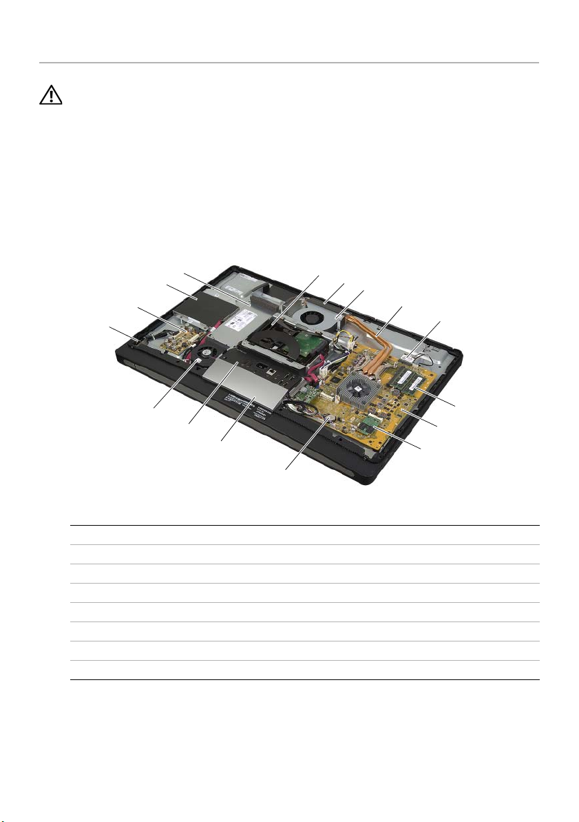
Inside View of Your Computer
4
3
2
1
16
15
14
13
1 power-button assembly 2 converter board
3 optical-drive assembly 4 power-supply unit
5 hard-drive assembly 6 cooling vents
7 processor heat-sink fan 8 processor heat-sink
9 wireless mini-card 10 memory module(s)
11 system board 12 mSATA mini-card
13 coin-cell battery 14 trim cover
15 I/O panel 16 power-supply fan
5
6
7
8
9
10
11
12
14 | Technical Overview
Page 15
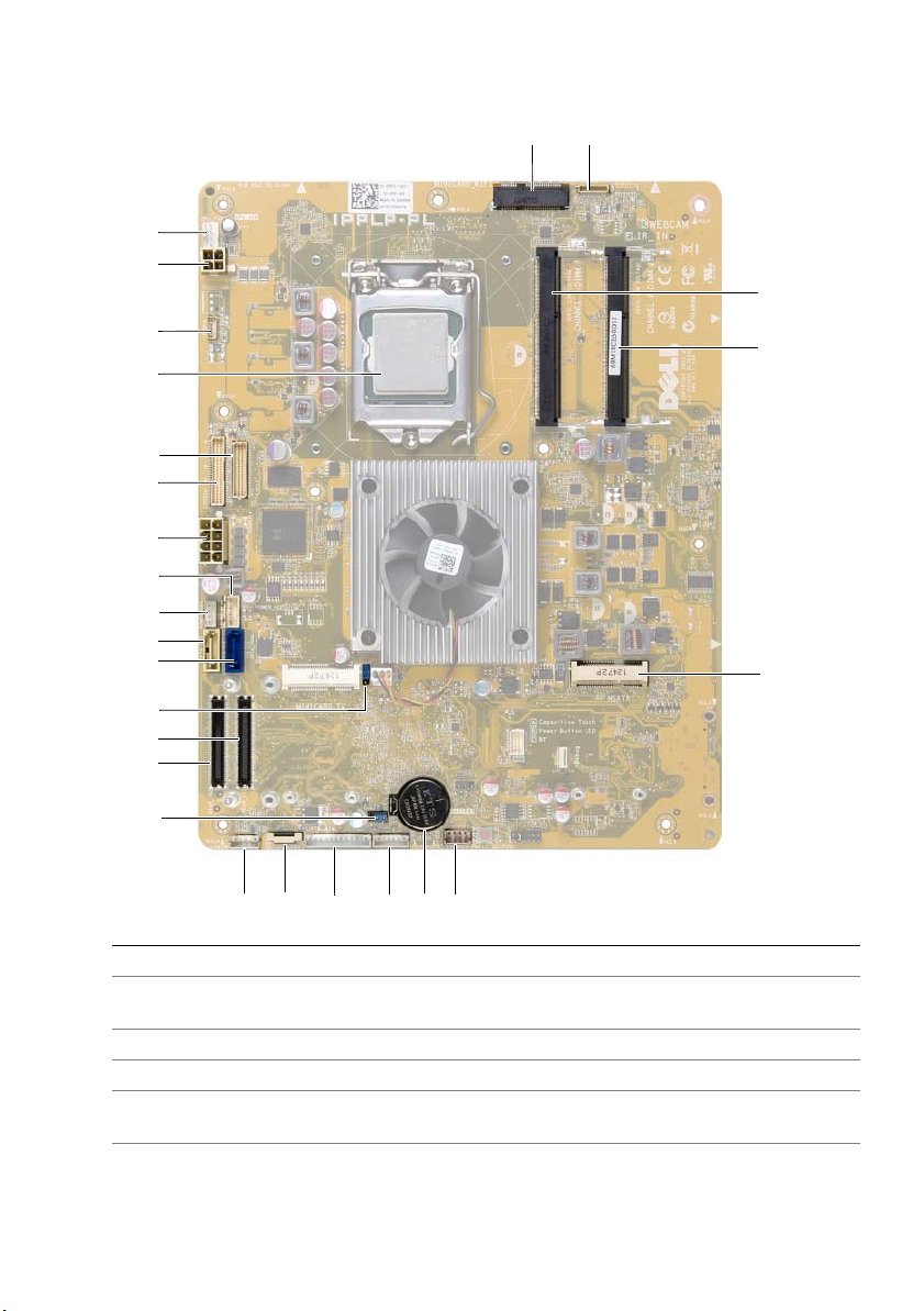
System-Board Components
26
25
12
3
24
4
23
22
21
20
19
18
17
16
5
15
14
13
12
11
10
1 wireless mini-card connector 2 camera-cable connector
3 memory-module connector
(CHANNEL A-DIMM)
5 mSATA mini-card connector 6 speaker-cable connector
7 coin-cell battery socket 8 power-button cable connector
9 converter-board cable connector 10 input source/display-settings controls
11 wireless keyboard/mouse receiver
cable connector
789 6
4 memory-module connector
(CHANNEL B-DIMM)
cable connector
12 CMOS jumper
Technical Overview | 15
Page 16

13 I/O-board connector (REAR_IO1) 14 I/O-board connector (REAR_IO2)
15 password jumper 16 hard-drive data-cable connector
17 optical-drive data-cable connector 18 optical-drive power-cable connector
19 hard-drive power-cable connector 20 main (8-pin) power-cable connector
21 LVDS-cable connector (LVDS1) 22 LVDS-cable connector (LVDS2)
23 processor socket 24 touchscreen-cable connector
25 processor (4-pin) power-cable
connector
26 processor heat-sink fan-cable connector
16 | Technical Overview
Page 17
Removing the Back Cover
WARNING: Before working inside your computer, read the safety information
that shipped with your computer and follow the steps in "Before You Begin" on
page 11. After working inside your computer, follow the instructions in "After
Working Inside Your Computer" on page 13. For additional safety best practices
information, see the Regulatory Compliance Homepage at
dell.com/regulatory_compliance.
Procedure
1 Place the computer face-down on a clean and flat surface.
2 Loosen the captive screws that secure the back cover to the inner frame.
3 Slide the back cover toward the top of the computer and lift the back cover off
the inner frame.
3
2
1
1 captive screws (2) 2 back cover
3inner frame
Removing the Back Cover | 17
Page 18

Replacing the Back Cover
WARNING: Before working inside your computer, read the safety information
that shipped with your computer and follow the steps in "Before You Begin" on
page 11. After working inside your computer, follow the instructions in "After
Working Inside Your Computer" on page 13. For additional safety best practices
information, see the Regulatory Compliance Homepage at
dell.com/regulatory_compliance.
Procedure
1 Place the back cover over the inner frame and slide the back cover toward the
bottom of the computer.
2 Tighten the captive screws that secure the back cover to the inner frame.
3 Follow the instructions in "After Working Inside Your Computer" on page 13.
18 | Replacing the Back Cover
Page 19
Removing the Trim Cover
WARNING: Before working inside your computer, read the safety information
that shipped with your computer and follow the steps in "Before You Begin" on
page 11. After working inside your computer, follow the instructions in "After
Working Inside Your Computer" on page 13. For additional safety best practices
information, see the Regulatory Compliance Homepage at
dell.com/regulatory_compliance.
Prerequisites
Remove the back cover. See "Removing the Back Cover" on page 17.
Procedure
1 Using a plastic scribe, press-in on the tabs to release the trim cover from the
inner frame.
2 Slide the trim cover toward the top of the computer and then lift the trim cover
off the chassis.
1
2
3
1 tabs (2) 2 plastic scribe
3trim cover
Removing the Trim Cover | 19
Page 20

Replacing the Trim Cover
WARNING: Before working inside your computer, read the safety information
that shipped with your computer and follow the steps in "Before You Begin" on
page 11. After working inside your computer, follow the instructions in "After
Working Inside Your Computer" on page 13. For additional safety best practices
information, see the Regulatory Compliance Homepage at
dell.com/regulatory_compliance.
Procedure
1 Insert the tabs at the bottom of the trim cover into the slots on the inner frame.
2 Press down on the trim cover until the tabs on the inner frame are secured in the
slots on either side of the trim cover.
Postrequisites
1 Replace the back cover. See "Replacing the Back Cover" on page 18.
2 Follow the instructions in "After Working Inside Your Computer" on page 13.
20 | Replacing the Trim Cover
Page 21
Removing the Stand
WARNING: Before working inside your computer, read the safety information
that shipped with your computer and follow the steps in "Before You Begin" on
page 11. After working inside your computer, follow the instructions in "After
Working Inside Your Computer" on page 13. For additional safety best practices
information, see the Regulatory Compliance Homepage at
dell.com/regulatory_compliance.
Prerequisites
Remove the Back Cover. See "Removing the Back Cover" on page 17.
Procedure
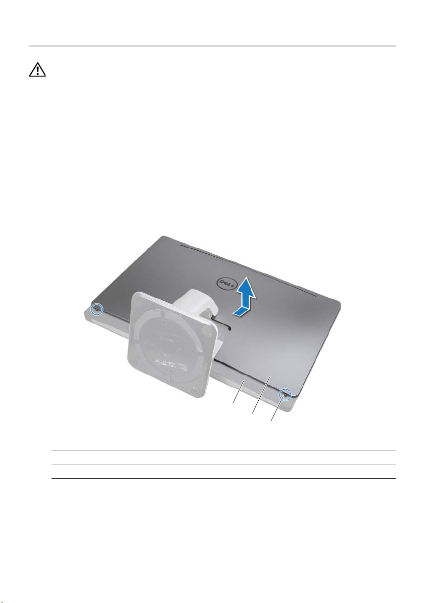
1 Remove the screws that secure the stand to the hard-drive cage.
2 Lift and slide the stand off the hard-drive cage.
1
2
1 screws (6) 2 stand
Removing the Stand | 21
Page 22

Replacing the Stand
WARNING: Before working inside your computer, read the safety information
that shipped with your computer and follow the steps in "Before You Begin" on
page 11. After working inside your computer, follow the instructions in "After
Working Inside Your Computer" on page 13. For additional safety best practices
information, see the Regulatory Compliance Homepage at
dell.com/regulatory_compliance.
Procedure
1 Insert the tab at the top of the stand into the slot on the hard-drive cage.
2 Align the screw holes on the stand with the screw holes on the hard-drive cage.
3 Replace the screws that secure the stand to the hard-drive cage.
Postrequisites
1 Replace the back cover. See "Replacing the Back Cover" on page 18.
2 Follow the instructions in "After Working Inside Your Computer" on page 13.
22 | Replacing the Stand
Page 23
Removing the Converter Board
WARNING: Before working inside your computer, read the safety information
that shipped with your computer and follow the steps in "Before You Begin" on
page 11. After working inside your computer, follow the instructions in "After
Working Inside Your Computer" on page 13. For additional safety best practices
information, see the Regulatory Compliance Homepage at
dell.com/regulatory_compliance.
Prerequisites
Remove the back cover. See "Removing the Back Cover" on page 17.
Procedure
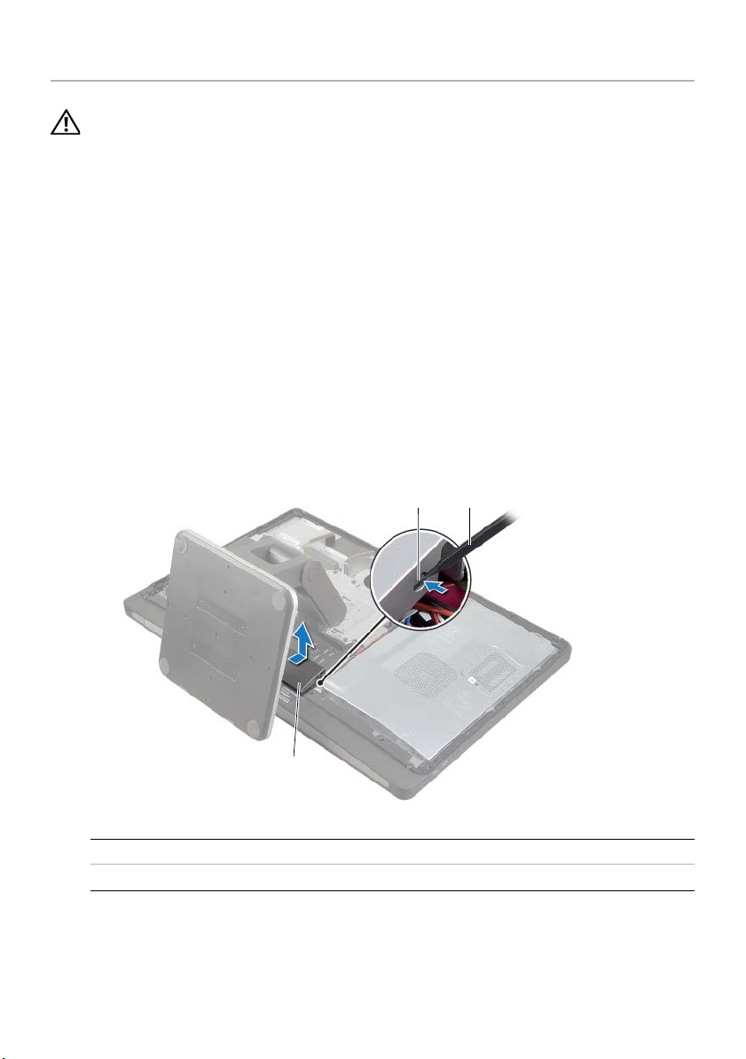
1 Lift the securing tab on the display-backlight cable connector and then disconnect
the display-backlight cable from the convertor board.
2 Disconnect the converter cable from the converter board.
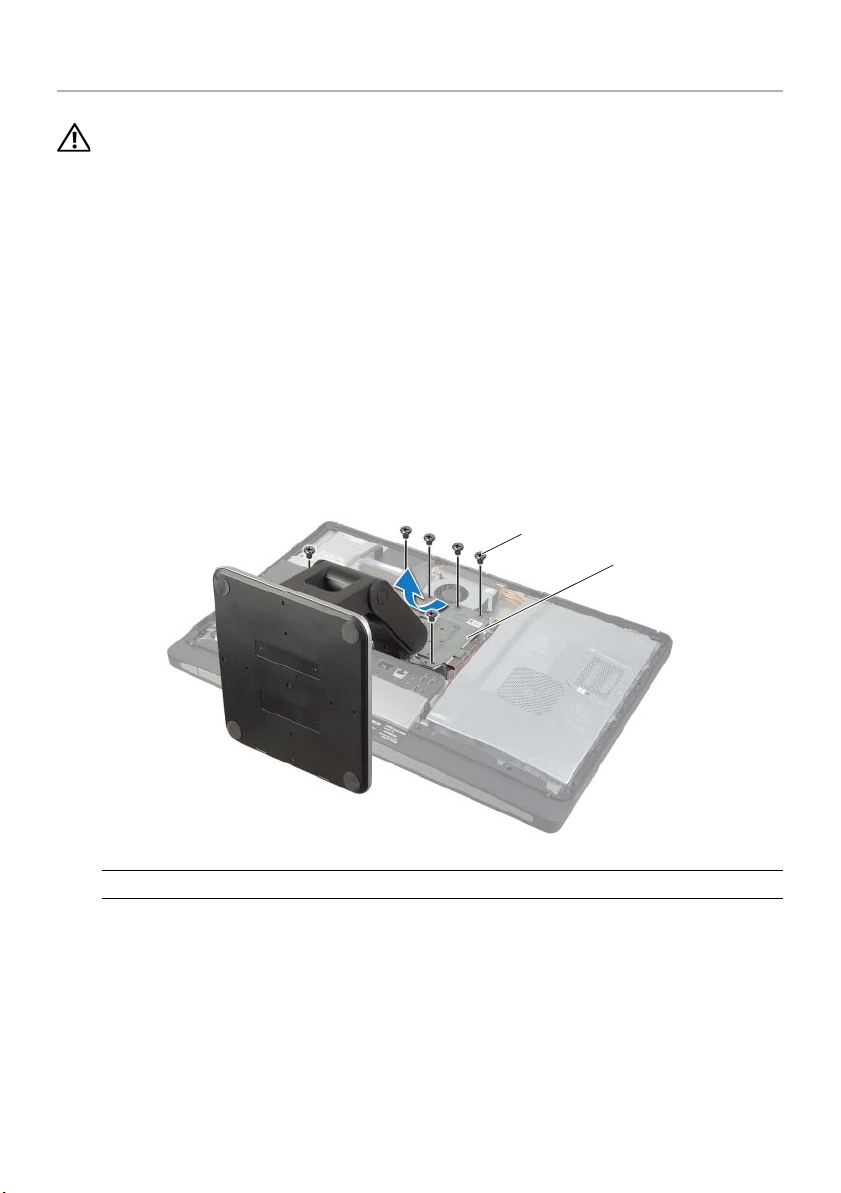
3 Remove the screws that secure the converter board to the middle cover.
4 Lift the converter board off the middle cover.
1
2
4
5
1 screws (2) 2 converter cable
3 converter board 4 securing tab
5 display-backlight cable
Removing the Converter Board | 23
3
Page 24

Replacing the Converter Board
WARNING: Before working inside your computer, read the safety information
that shipped with your computer and follow the steps in "Before You Begin" on
page 11. After working inside your computer, follow the instructions in "After
Working Inside Your Computer" on page 13. For additional safety best practices
information, see the Regulatory Compliance Homepage at
dell.com/regulatory_compliance.
Procedure
1 Align the screw holes on the converter board with the screw holes on the
middle cover.
2 Replace the screws that secure the converter board to the middle cover.
3 Connect the converter cable to the converter board.
4 Connect the display-backlight cable to the convertor board and secure the tab.
Postrequisites
1 Replace the back cover. See "Replacing the Back Cover" on page 18.
2 Follow the instructions in "After Working Inside Your Computer" on page 13.
24 | Replacing the Converter Board
Page 25
Removing the Optical Drive
WARNING: Before working inside your computer, read the safety information
that shipped with your computer and follow the steps in "Before You Begin" on
page 11. After working inside your computer, follow the instructions in "After
Working Inside Your Computer" on page 13. For additional safety best practices
information, see the Regulatory Compliance Homepage at
dell.com/regulatory_compliance.
Prerequisites
Remove the back cover. See "Removing the Back Cover" on page 17.
Procedure
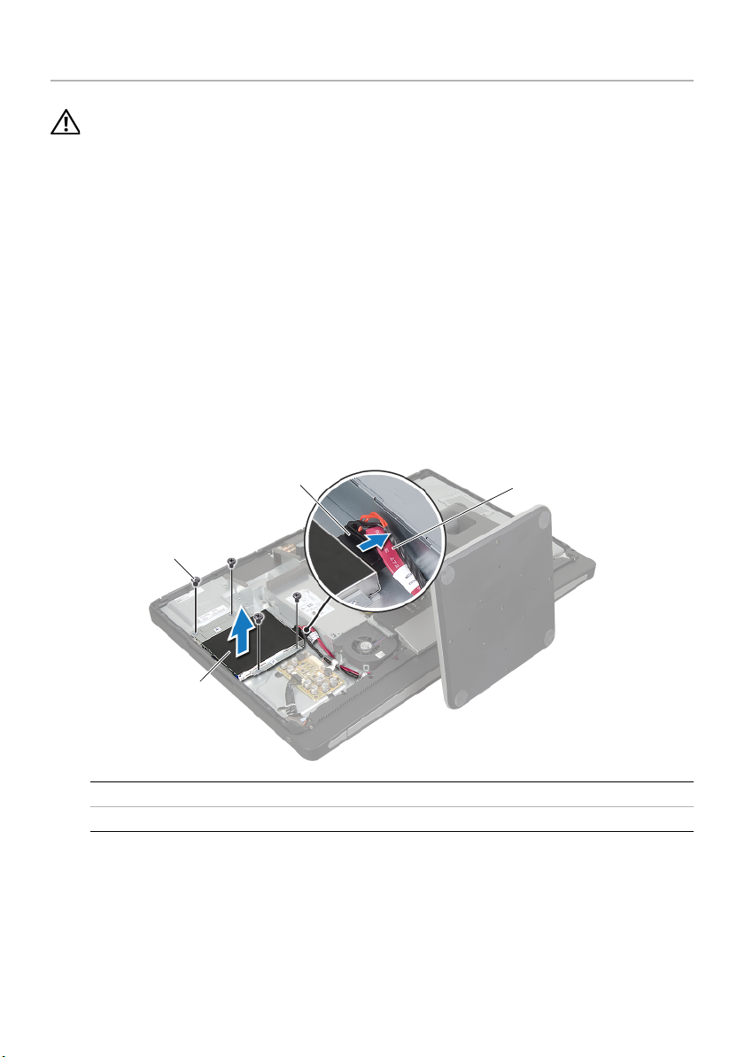
1 Remove the screws that secure the optical-drive assembly to the middle cover.
2 Gently lift the optical-drive assembly from the middle cover and disconnect the
power and data-cable connector from the optical-drive assembly.
3
2
1
1 optical-drive assembly 2 screws (4)
3 power and data-cable connector 4 power and data cable
4
Removing the Optical Drive | 25
Page 26
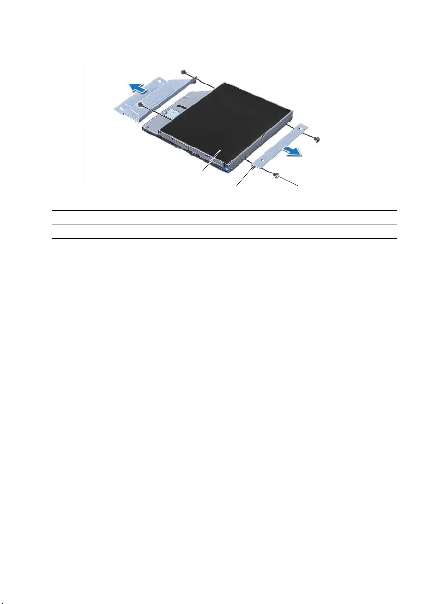
3 Remove the screws that secure the optical-drive brackets to the optical drive.
4 Remove the optical-drive brackets from the optical drive.
3
2
1 screws (4) 2 optical-drive brackets (2)
3 optical drive
1
26 | Removing the Optical Drive
Page 27

Replacing the Optical Drive
WARNING: Before working inside your computer, read the safety information
that shipped with your computer and follow the steps in "Before You Begin" on
page 11. After working inside your computer, follow the instructions in "After
Working Inside Your Computer" on page 13. For additional safety best practices
information, see the Regulatory Compliance Homepage at
dell.com/regulatory_compliance.
Procedure
1 Align the screw holes on the optical-drive brackets with the screw holes on the
optical drive and replace the screws that secure the optical-drive brackets to the
optical drive.
2 Connect the power and data-cable connector to the optical-drive assembly.
3 Align the screw holes on the optical-drive assembly with the screw holes on the
chassis.
4 Replace the screws that secure the optical-drive assembly to the chassis.
Postrequisites
1 Replace the back cover. See "Replacing the Back Cover" on page 18.
2 Follow the instructions in "After Working Inside Your Computer" on page 13.
Replacing the Optical Drive | 27
Page 28
Removing the Memory Module(s)
WARNING: Before working inside your computer, read the safety information
that shipped with your computer and follow the steps in "Before You Begin" on
page 11. After working inside your computer, follow the instructions in "After
Working Inside Your Computer" on page 13. For additional safety best practices
information, see the Regulatory Compliance Homepage at
dell.com/regulatory_compliance.
Prerequisites
Remove the Back Cover. See "Removing the Back Cover" on page 17.
Procedure
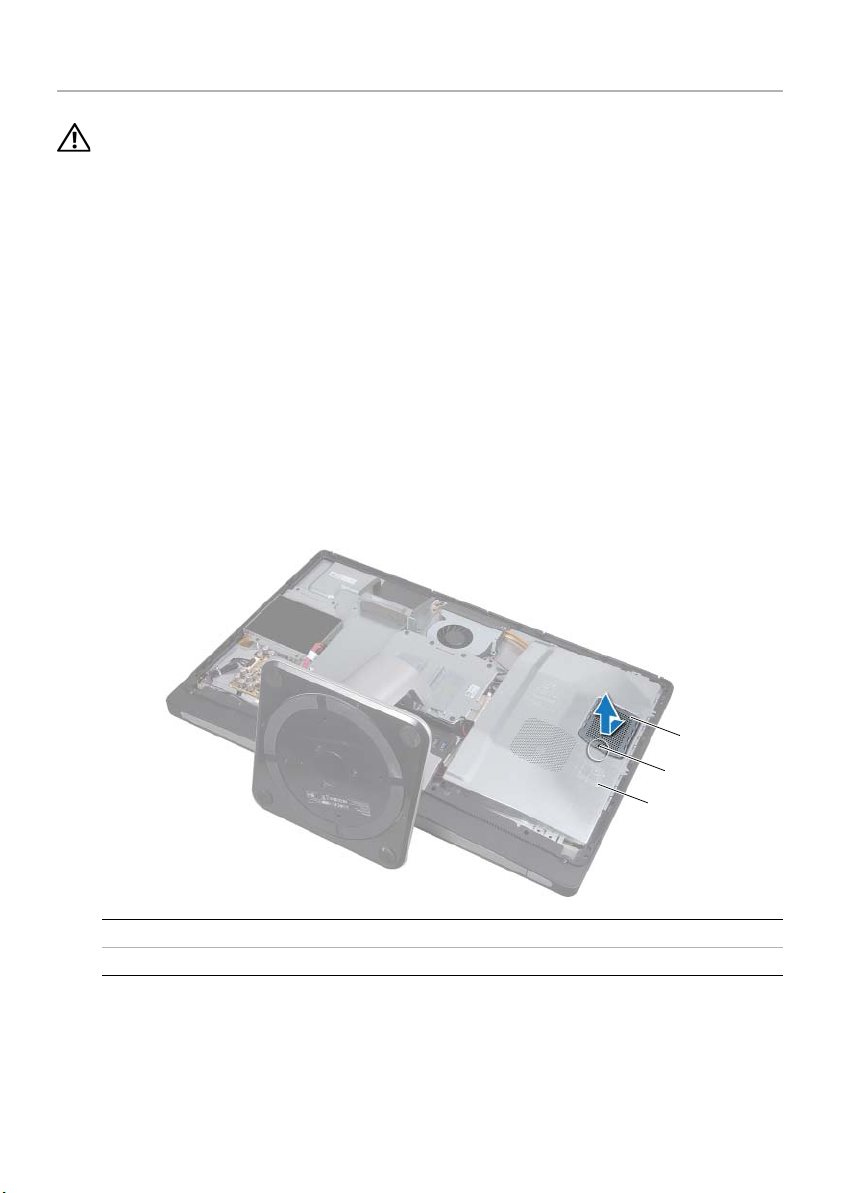
1 Remove the screw that secures the memory-module shield to the system-board
shield.
2 Slide the memory-module shield toward the bottom of the computer and lift it off
the system-board shield.
1 memory-module shield 2 screw
3system-board shield
28 | Removing the Memory Module(s)
1
2
3
Page 29
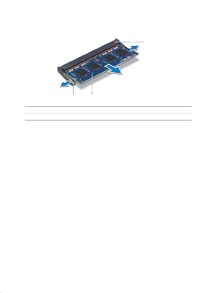
3 Use your fingertips to spread apart the securing clips on each end of the memory
module connector until the memory module pops up.
4 Remove the memory module from the memory-module connector.
3
1
1 securing-clips (2) 2 memory module
3 memory-module connector
2
Removing the Memory Module(s) | 29
Page 30
Replacing the Memory Module(s)
WARNING: Before working inside your computer, read the safety information
that shipped with your computer and follow the steps in "Before You Begin" on
page 11. After working inside your computer, follow the instructions in "After
Working Inside Your Computer" on page 13. For additional safety best practices
information, see the Regulatory Compliance Homepage at
dell.com/regulatory_compliance.
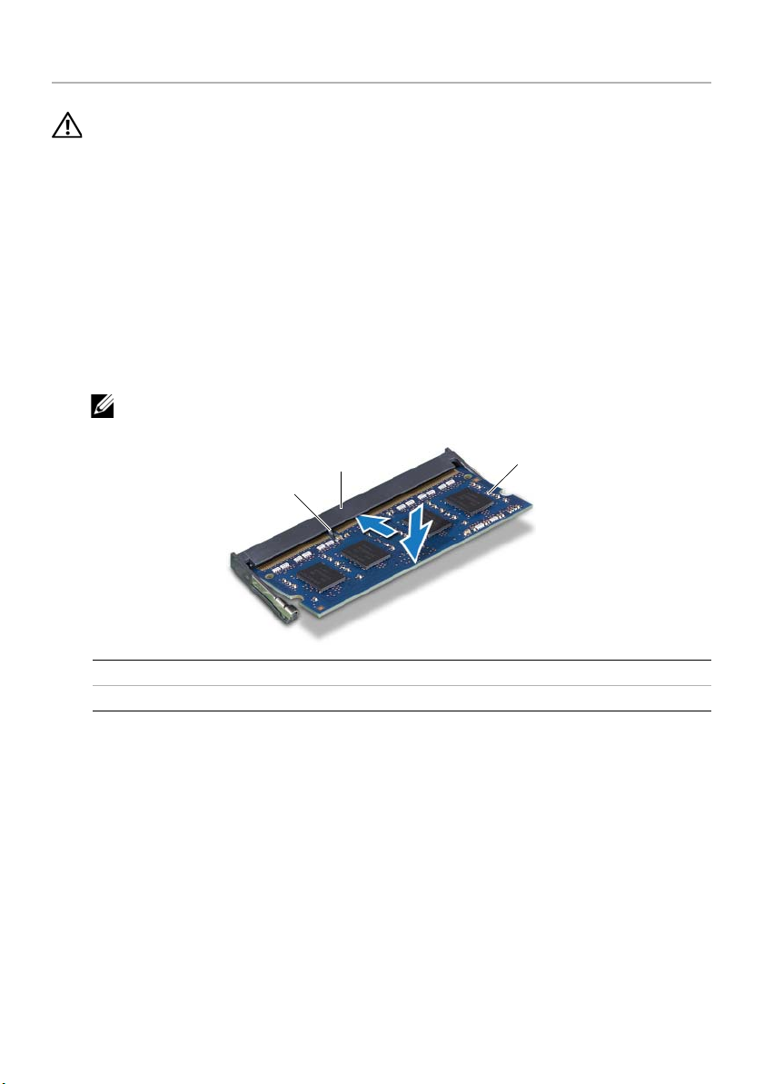
Procedure
1 Align the notch on the memory module with the tab on the
memory-module connector.
2 Slide the memory module firmly into the connector at a 45-degree angle
and press the memory module down until it clicks into place.
NOTE: If you do not hear the click, remove the memory module and reinstall it.
32
1
1 tab 2 memory-module connector
3memory module
3 Slide the tabs on the memory-module shield into the slots on the
system-board shield and slide the memory-module toward the top of the
computer.
4 Replace the screw that secures the memory-module shield to the
system-board shield.
Postrequisites
1 Replace the back cover. See "Replacing the Back Cover" on page 18.
2 Follow the instructions in "After Working Inside Your Computer" on page 13.
30 | Replacing the Memory Module(s)
Page 31

Removing the System-Board Shield
WARNING: Before working inside your computer, read the safety information
that shipped with your computer and follow the steps in "Before You Begin" on
page 11. After working inside your computer, follow the instructions in "After
Working Inside Your Computer" on page 13. For additional safety best practices
information, see the Regulatory Compliance Homepage at
dell.com/regulatory_compliance.
Prerequisites
Remove the back cover. See "Removing the Back Cover" on page 17.
Procedure
1 Remove the screws that secure the system-board shield to the middle cover.
2 Lift the system-board shield off the middle cover.
1
1 screws (8) 2 system-board shield
Removing the System-Board Shield | 31
2
Page 32

Replacing the System-Board Shield
WARNING: Before working inside your computer, read the safety information
that shipped with your computer and follow the steps in "Before You Begin" on
page 11. After working inside your computer, follow the instructions in "After
Working Inside Your Computer" on page 13. For additional safety best practices
information, see the Regulatory Compliance Homepage at
dell.com/regulatory_compliance.
Procedure
1 Align the screw holes on the system-board shield with the screw holes on
the middle cover.
2 Replace the screws that secure the system-board shield to the middle cover.
Postrequisites
1 Replace the back cover. See "Replacing the Back Cover" on page 18.
2 Follow the instructions in "After Working Inside Your Computer" on page 13.
32 | Replacing the System-Board Shield
Page 33

Removing the Power-Supply Fan
WARNING: Before working inside your computer, read the safety information
that shipped with your computer and follow the steps in "Before You Begin" on
page 11. After working inside your computer, follow the instructions in "After
Working Inside Your Computer" on page 13. For additional safety best practices
information, see the Regulatory Compliance Homepage at
dell.com/regulatory_compliance.
Prerequisites
Remove the back cover. See "Removing the Back Cover" on page 17.
Procedure
1 Lift the securing tab and disconnect the power-supply fan cable from the
power-supply unit.
2 Remove the screws that secure the power-supply fan to the middle cover.
3 Gently lift the power-supply fan and ease the power-supply fan cable from
under the I/O-board assembly.
4 Lift the power-supply fan and slide it off the tab on the I/O-board assembly.
4
3
2
1
1 power-supply fan 2 screws (2)
3 power-supply fan cable 4 securing tab
Removing the Power-Supply Fan | 33
Page 34

Replacing the Power-Supply Fan
WARNING: Before working inside your computer, read the safety information
that shipped with your computer and follow the steps in "Before You Begin" on
page 11. After working inside your computer, follow the instructions in "After
Working Inside Your Computer" on page 13. For additional safety best practices
information, see the Regulatory Compliance Homepage at
dell.com/regulatory_compliance.
Procedure
1 Route the power-supply fan cable under the I/O-board assembly and then connect
the power-supply fan cable to the power-supply unit.
2 Slide the power-supply fan under the tab on the I/O-board assembly and align the
screw holes on the power-supply fan with the screw holes on the middle cover.
3 Replace the screws that secure the power-supply fan to the middle cover.
Postrequisites
1 Replace the back cover. See "Replacing the Back Cover" on page 18.
2 Follow the instructions in "After Working Inside Your Computer" on page 13.
34 | Replacing the Power-Supply Fan
Page 35

Removing the Hard Drive
WARNING: Before working inside your computer, read the safety information
that shipped with your computer and follow the steps in "Before You Begin" on
page 11. After working inside your computer, follow the instructions in "After
Working Inside Your Computer" on page 13. For additional safety best practices
information, see the Regulatory Compliance Homepage at
dell.com/regulatory_compliance.
CAUTION: To avoid data loss, do not remove the hard drive while the computer is
in Sleep or On state.
CAUTION: Hard drives are extremely fragile. Exercise care when handling the
hard drive.
Prerequisites
1 Remove the back cover. See "Removing the Back Cover" on page 17.
2 Remove the stand. See "Removing the Stand" on page 21.
Procedure
1 Using the straps on the hard-drive assembly, gently lift the hard-drive assembly out
of the hard-drive cage.
2 Disconnect the power and data-cable connector from the hard-drive assembly.
1
2
4
3
1 straps (2) 2 power and data-cable connector
3 power and data cable 4 hard-drive assembly
Removing the Hard Drive | 35
Page 36

3 Remove the screws that secure the straps to the hard drive and remove the straps
from the hard drive.
1
2
3
1 screws (4) 2 hard drive
3straps (2)
36 | Removing the Hard Drive
Page 37

Replacing the Hard Drive
WARNING: Before working inside your computer, read the safety information
that shipped with your computer and follow the steps in "Before You Begin" on
page 11. After working inside your computer, follow the instructions in "After
Working Inside Your Computer" on page 13. For additional safety best practices
information, see the Regulatory Compliance Homepage at
dell.com/regulatory_compliance.
CAUTION: Hard drives are extremely fragile. Exercise care when handling the
hard drive.
Procedure
1 Align the screw holes on the straps with the screw holes on the hard drive and
replace the screws that secure the straps to the hard drive.
2 Connect the power and data-cable connector to the hard-drive assembly.
3 With the straps facing up, align the hard-drive assembly screws with the slots on the
hard-drive cage, and then gently press down the hard-drive assembly.
Postrequisites
1 Replace the stand. See "Replacing the Stand" on page 22.
2 Replace the back cover. See "Replacing the Back Cover" on page 18.
3 Follow the instructions in "After Working Inside Your Computer" on page 13.
Replacing the Hard Drive | 37
Page 38

Removing the Hard-Drive Cage
WARNING: Before working inside your computer, read the safety information
that shipped with your computer and follow the steps in "Before You Begin" on
page 11. After working inside your computer, follow the instructions in "After
Working Inside Your Computer" on page 13. For additional safety best practices
information, see the Regulatory Compliance Homepage at
dell.com/regulatory_compliance.
Prerequisites
1 Remove the back cover. See "Removing the Back Cover" on page 17.
2 Remove the stand. See "Removing the Stand" on page 21.
3 Follow step 1 to step 2 in "Removing the Hard Drive" on page 35.
Procedure
1 Remove the screws that secure the hard-drive cage to the middle cover.
2 Remove the power and date cable from the routing guides on the hard-drive cage.
3 Lift the hard-drive cage off the middle cover.
1
2
1 screws (4) 2 hard-drive cage
38 | Removing the Hard-Drive Cage
Page 39

Replacing the Hard-Drive Cage
WARNING: Before working inside your computer, read the safety information
that shipped with your computer and follow the steps in "Before You Begin" on
page 11. After working inside your computer, follow the instructions in "After
Working Inside Your Computer" on page 13. For additional safety best practices
information, see the Regulatory Compliance Homepage at
dell.com/regulatory_compliance.
Procedure
1 Align the screw holes on the hard-drive cage with the screw holes on the
middle cover.
2 Replace the screws that secure the hard-drive cage to the middle cover.
Postrequisites
1 Follow step 2 to step 3 in "Replacing the Hard Drive" on page 37.
2 Replace the stand. See "Replacing the Stand" on page 22.
3 Replace the back cover. See "Replacing the Back Cover" on page 18.
4 Follow the instructions in "After Working Inside Your Computer" on page 13.
Replacing the Hard-Drive Cage | 39
Page 40

Removing the I/O Panel
WARNING: Before working inside your computer, read the safety information
that shipped with your computer and follow the steps in "Before You Begin" on
page 11. After working inside your computer, follow the instructions in "After
Working Inside Your Computer" on page 13. For additional safety best practices
information, see the Regulatory Compliance Homepage at
dell.com/regulatory_compliance.
Prerequisites
1 Remove the back cover. See "Removing the Back Cover" on page 17.
2 Remove the stand. See "Removing the Stand" on page 21.
3 Remove the trim cover. See "Removing the Trim Cover" on page 19.
Procedure
1 Push the I/O panel towards the top of the computer and then pivot the
I/O panel upward.
2 Ease the securing tabs on the I/O panel and lift the I/O panel off the
I/O-board assembly.
1
2
1 securing tabs 2 I/O panel
40 | Removing the I/O Panel
Page 41

Replacing the I/O Panel
WARNING: Before working inside your computer, read the safety information
that shipped with your computer and follow the steps in "Before You Begin" on
page 11. After working inside your computer, follow the instructions in "After
Working Inside Your Computer" on page 13. For additional safety best practices
information, see the Regulatory Compliance Homepage at
dell.com/regulatory_compliance.
Procedure
1 Align the slots on the I/O panel with the ports on the I/O-board assembly.
2 Press down on the I/O panel until it snaps into place.
Postrequisites
1 Replace the trim cover. See "Replacing the Trim Cover" on page 20.
2 Replace the stand. See "Replacing the Stand" on page 22.
3 Replace the back cover. See "Replacing the Back Cover" on page 18.
4 Follow the instructions in "After Working Inside Your Computer" on page 13.
Replacing the I/O Panel | 41
Page 42

Removing the Coin-Cell Battery
WARNING: Before working inside your computer, read the safety information
that shipped with your computer and follow the steps in "Before You Begin" on
page 11. After working inside your computer, follow the instructions in "After
Working Inside Your Computer" on page 13. For additional safety best practices
information, see the Regulatory Compliance Homepage at
dell.com/regulatory_compliance.
CAUTION: Removing the coin-cell battery resets the BIOS settings to default.
It is recommended that you note the BIOS settings before removing the coin-cell
battery.
Prerequisites
1 Remove the back cover. See "Removing the Back Cover" on page 17.
2 Remove the system-board shield. See "Removing the System-Board Shield" on
page 31.
Procedure
1 Locate the coin-cell battery socket. See "System-Board Components" on page 15.
2 Press the securing clip away from the coin-cell battery until the coin-cell battery
pops out.
12
1 coin-cell battery 2 securing clip
3 Lift the coin-cell battery out of its socket.
42 | Removing the Coin-Cell Battery
Page 43

Replacing the Coin-Cell Battery
WARNING: Before working inside your computer, read the safety information
that shipped with your computer and follow the steps in "Before You Begin" on
page 11. After working inside your computer, follow the instructions in "After
Working Inside Your Computer" on page 13. For additional safety best practices
information, see the Regulatory Compliance Homepage at
dell.com/regulatory_compliance.
WARNING: The battery may explode if installed incorrectly. Replace the battery
only with the same or equivalent type. Discard used batteries according to the
manufacturer’s instructions.
Procedure
With the positive-side facing up, snap the coin-cell battery into the coin-cell battery
socket on the system board.
Postrequisites
1 Replace the system-board shield. See "Replacing the System-Board Shield" on
page 32.
2 Replace the back cover. See "Replacing the Back Cover" on page 18.
3 Follow the instructions in "After Working Inside Your Computer" on page 13.
Replacing the Coin-Cell Battery | 43
Page 44

Removing the Wireless Mini-Card
WARNING: Before working inside your computer, read the safety information
that shipped with your computer and follow the steps in "Before You Begin" on
page 11. After working inside your computer, follow the instructions in "After
Working Inside Your Computer" on page 13. For additional safety best practices
information, see the Regulatory Compliance Homepage at
dell.com/regulatory_compliance.
Prerequisites
1 Remove the back cover. See "Removing the Back Cover" on page 17.
2 Remove the system-board shield. See "Removing the System-Board Shield" on
page 31.
Procedure
1 Locate the wireless mini-card. See "System-Board Components" on page 15.
2 Disconnect the antenna cables from the wireless mini-card.
3 Remove the screws that secure the wireless mini-card to the system board.
1
1 screws (2) 2 antenna cables (2)
44 | Removing the Wireless Mini-Card
2
Page 45
4 Slide and remove the wireless mini-card out of the wireless mini-card connector.
21
1 wireless mini-card connector 2 wireless mini-card
Removing the Wireless Mini-Card | 45
Page 46

Replacing the Wireless Mini-Card
WARNING: Before working inside your computer, read the safety information
that shipped with your computer and follow the steps in "Before You Begin" on
page 11. After working inside your computer, follow the instructions in "After
Working Inside Your Computer" on page 13. For additional safety best practices
information, see the Regulatory Compliance Homepage at
dell.com/regulatory_compliance.
Procedure
CAUTION: To avoid damage to the mini-card, ensure that no cables are placed
under the wireless mini-card.
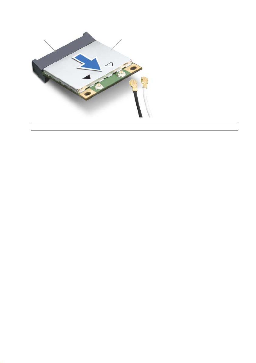
1 Align the notch on the wireless mini-card with the tab on the wireless
mini-card connector.
2 Insert the wireless mini-card at a 45-degree angle into the wireless
mini-card connector.
3 Press the outer end of the wireless mini-card down and replace the screws
that secure the wireless mini-card to the system board.
4 Connect the antenna cables to the wireless mini-card.
The following table provides the wireless-antenna cable color schemes for
the wireless mini-cards supported by your computer.
Connectors on the mini-card Wireless-antenna cable color
schemes
WLAN + Bluetooth (2 cables)
Main WLAN + Bluetooth (white triangle)
Auxiliary WLAN + Bluetooth (black triangle)
white
black
Postrequisites
1 Replace the system-board shield. See "Replacing the System-Board Shield" on
page 32.
2 Replace the back cover. See "Replacing the Back Cover" on page 18.
3 Follow the instructions in "After Working Inside Your Computer" on page 13.
46 | Replacing the Wireless Mini-Card
Page 47

Removing the mSATA Mini-Card
WARNING: Before working inside your computer, read the safety information
that shipped with your computer and follow the steps in "Before You Begin" on
page 11. After working inside your computer, follow the instructions in "After
Working Inside Your Computer" on page 13. For additional safety best practices
information, see the Regulatory Compliance Homepage at
dell.com/regulatory_compliance.
Prerequisites
1 Remove the back cover. See "Removing the Back Cover" on page 17.
2 Remove the system-board shield. See "Removing the System-Board Shield" on
page 31.
Procedure
1 Remove the screws that secure the mSATA mini-card to the system board.
2 Slide and remove the mSATA mini-card from the mSATA mini-card connector.
1
1 screws (2) 2 mSATA mini-card connector
3mSATA mini-card
Removing the mSATA Mini-Card | 47
2
3
Page 48

Replacing the mSATA Mini-Card
WARNING: Before working inside your computer, read the safety information
that shipped with your computer and follow the steps in "Before You Begin" on
page 11. After working inside your computer, follow the instructions in "After
Working Inside Your Computer" on page 13. For additional safety best practices
information, see the Regulatory Compliance Homepage at
dell.com/regulatory_compliance.
Procedure
1 Align the notch on the mSATA mini-card with the tab on the
mSATA mini-card connector.
2 Insert the mSATA mini-card at a 45-degree angle into the
mSATA mini-card connector.
3 Replace the screws that secure the mSATA mini-card to the system board.
Postrequisites
1 Replace the system-board shield. See "Replacing the System-Board Shield" on
page 32.
2 Replace the back cover. See "Replacing the Back Cover" on page 18.
3 Follow the instructions in "After Working Inside Your Computer" on page 13.
48 | Replacing the mSATA Mini-Card
Page 49

Removing the Inner Frame
WARNING: Before working inside your computer, read the safety information
that shipped with your computer and follow the steps in "Before You Begin" on
page 11. After working inside your computer, follow the instructions in "After
Working Inside Your Computer" on page 13. For additional safety best practices
information, see the Regulatory Compliance Homepage at
dell.com/regulatory_compliance.
Prerequisites
1 Remove the back cover. See "Removing the Back Cover" on page 17.
2 Remove the trim cover. See "Removing the Trim Cover" on page 19.
3 Remove the stand. See "Removing the Stand" on page 21.
4 Remove the I/O panel. See "Removing the I/O Panel" on page 40.
Procedure
1 Remove the screws that secure the inner frame to the display bezel.
2 Gently pry the inner frame from the sides and lift the inner frame off the
display bezel.
1 inner frame 2 screws (18)
Removing the Inner Frame | 49
1
2
Page 50

Replacing the Inner Frame
WARNING: Before working inside your computer, read the safety information
that shipped with your computer and follow the steps in "Before You Begin" on
page 11. After working inside your computer, follow the instructions in "After
Working Inside Your Computer" on page 13. For additional safety best practices
information, see the Regulatory Compliance Homepage at
dell.com/regulatory_compliance.
Procedure
1 Align the screw holes on the inner frame with the screw holes on the display bezel.
NOTE: Ensure that all cables are routed through their routing guides and
no cables are placed between the inner frame and the display bezel.
2 Replace the screws that secure the inner frame to the display bezel.
Postrequisites
1 Replace the I/O panel. See "Replacing the I/O Panel" on page 41.
2 Replace the stand. See "Replacing the Stand" on page 22.
3 Replace the trim cover. See "Replacing the Trim Cover" on page 20.
4 Replace the back cover. "Replacing the Back Cover" on page 18.
5 Follow the instructions in "After Working Inside Your Computer" on page 13.
50 | Replacing the Inner Frame
Page 51

Removing the Processor Heat-Sink Fan
WARNING: Before working inside your computer, read the safety information
that shipped with your computer and follow the steps in "Before You Begin" on
page 11. After working inside your computer, follow the instructions in "After
Working Inside Your Computer" on page 13. For additional safety best practices
information, see the Regulatory Compliance Homepage at
dell.com/regulatory_compliance.
Prerequisites
1 Remove the back cover. See "Removing the Back Cover" on page 17.
2 Remove the system-board shield. See "Removing the System-Board Shield" on
page 31.
Procedure
1 Disconnect the processor heat-sink fan cable from the system board.
2 Remove the screws that secure the processor heat-sink fan to the middle cover.
3 Lift the processor heat-sink fan and slide it out off the tab on the hard-drive cage.
1
1 screw (3) 2 processor heat-sink fan cable
3 processor heat-sink fan
Removing the Processor Heat-Sink Fan | 51
2
3
Page 52

Replacing the Processor Heat-Sink Fan
WARNING: Before working inside your computer, read the safety information
that shipped with your computer and follow the steps in "Before You Begin" on
page 11. After working inside your computer, follow the instructions in "After
Working Inside Your Computer" on page 13. For additional safety best practices
information, see the Regulatory Compliance Homepage at
dell.com/regulatory_compliance.
Procedure
1 Slide the processor heat-sink fan under the tab on the hard-drive cage and align
the screw holes on the processor heat-sink fan with the screw holes on
the middle cover.
2 Replace the screws that secure the processor heat-sink fan to the middle cover.
3 Connect the processor heat-sink fan cable to the system board.
Postrequisites
1 Replace the system-board shield. See "Replacing the System-Board Shield" on
page 32.
2 Replace the back cover. See "Replacing the Back Cover" on page 18.
3 Follow the instructions in "After Working Inside Your Computer" on page 13.
52 | Replacing the Processor Heat-Sink Fan
Page 53

Removing the Processor Heat-Sink
WARNING: Before working inside your computer, read the safety information
that shipped with your computer and follow the steps in "Before You Begin" on
page 11. After working inside your computer, follow the instructions in "After
Working Inside Your Computer" on page 13. For additional safety best practices
information, see the Regulatory Compliance Homepage at
dell.com/regulatory_compliance.
Prerequisites
1 Remove the back cover. See "Removing the Back Cover" on page 17.
2 Remove the system-board shield. See "Removing the System-Board Shield" on
page 31.
Procedure
1 Remove the screw that secures the cooling vents and the grounding cable to
the middle cover.
2 In sequential order (indicated on the processor heat-sink), loosen the captive
screws that secure the processor heat-sink to the system board.
3 Lift the processor heat-sink off the system board.
1
1 grounding cable 2 screw
3 cooling vents 4 processor heat-sink
5 captive screws (4)
Removing the Processor Heat-Sink | 53
2
3
4
5
Page 54

Replacing the Processor Heat-Sink
WARNING: Before working inside your computer, read the safety information
that shipped with your computer and follow the steps in "Before You Begin" on
page 11. After working inside your computer, follow the instructions in "After
Working Inside Your Computer" on page 13. For additional safety best practices
information, see the Regulatory Compliance Homepage at
dell.com/regulatory_compliance.
Procedure
NOTE: The original thermal grease can be reused if the original system board and
heat sink are reinstalled together. If either the system board or the heat sink is
replaced with a new one, use the thermal pad provided in the kit to ensure that
thermal conductivity is achieved.
1 Clean the thermal grease from the bottom of the processor heat-sink and reapply
the thermal grease.
2 Align the captive screws on the processor heat-sink with the screw holes on the
system board.
3 In sequential order (indicated on the processor heat-sink), tighten the captive
screws that secure the processor heat-sink to the system board.
4 Replace the screw that secures the cooling vents and the grounding cable to
the middle cover.
Postrequisites
1 Replace the system-board shield. See "Replacing the System-Board Shield" on
page 32.
2 Replace the back cover. See "Replacing the Back Cover" on page 18.
3 Follow the instructions in "After Working Inside Your Computer" on page 13.
54 | Replacing the Processor Heat-Sink
Page 55

Removing the Processor
WARNING: Before working inside your computer, read the safety information
that shipped with your computer and follow the steps in "Before You Begin" on
page 11. After working inside your computer, follow the instructions in "After
Working Inside Your Computer" on page 13. For additional safety best practices
information, see the Regulatory Compliance Homepage at
dell.com/regulatory_compliance.
CAUTION: Processors are extremely fragile. Handle the processor only by the
edges and do not touch the metal pins.
Prerequisites
1 Remove the back cover. See "Removing the Back Cover" on page 17.
2 Remove the system-board shield. See "Removing the System-Board Shield" on
page 31.
3 Remove the processor heat-sink. See "Removing the Processor Heat-Sink" on
page 53.
Procedure
1 Press the release-lever down and then pull it outwards to release it from the
securing tab.
2 Extend the release-lever completely to open the processor cover.
3 Gently lift the processor and remove it from the processor socket.
1 42 3
1 release lever 2 processor cover
3 securing tab 4 processor
Removing the Processor | 55
Page 56

Replacing the Processor
WARNING: Before working inside your computer, read the safety information
that shipped with your computer and follow the steps in "Before You Begin" on
page 11. After working inside your computer, follow the instructions in "After
Working Inside Your Computer" on page 13. For additional safety best practices
information, see the Regulatory Compliance Homepage at
dell.com/regulatory_compliance.
Procedure
1 Ensure that the release lever on the processor socket is fully extended in the
open position.
CAUTION: You must position the processor correctly in the processor socket to
avoid permanent damage to the processor.
2 Align the notches on the processor with the tabs on the processor socket.
3 Align the pin-1 corner on the processor with the pin-1 corner on the
processor socket, and then place the processor in the processor socket.
CAUTION: Ensure that the processor-cover notch is positioned underneath the
alignment post.
4 When the processor is fully seated in the socket, close the processor cover.
5 Pivot the release-lever down and place it under the tab on the processor cover.
1
23 456 7
1 processor pin-1 indicator 2 processor
3 alignment tabs (2) 4 alignment post
5 processor-cover notch 6 processor cover
7release lever
56 | Replacing the Processor
Page 57

Postrequisites
1 Replace the processor heat-sink. See "Replacing the Processor Heat-Sink" on
page 54.
2 Replace the system-board shield. See "Replacing the System-Board Shield" on
page 32.
3 Replace the back cover. See "Replacing the Back Cover" on page 18.
4 Follow the instructions in "After Working Inside Your Computer" on page 13.
Replacing the Processor | 57
Page 58

Removing the Power-Supply Unit
WARNING: Before working inside your computer, read the safety information
that shipped with your computer and follow the steps in "Before You Begin" on
page 11. After working inside your computer, follow the instructions in "After
Working Inside Your Computer" on page 13. For additional safety best practices
information, see the Regulatory Compliance Homepage at
dell.com/regulatory_compliance.
Prerequisites
1 Remove the back cover. See "Removing the Back Cover" on page 17.
2 Remove the trim cover. See "Removing the Trim Cover" on page 19.
3 Remove the stand. See "Removing the Stand" on page 21.
4 Remove the I/O panel. See "Removing the I/O Panel" on page 40.
5 Remove the system-board shield. See "Removing the System-Board Shield" on
page 31.
58 | Removing the Power-Supply Unit
Page 59

Procedure
1 Press the securing clips and disconnect the main power-supply cable and processor
power-supply cable from the system board.
2 Remove the main power-supply cable and processor power-supply cable from
their routing guides.
3 Press the securing clip on the power-port cable connector and disconnect the
power-port cable from the power-supply unit.
4 Disconnect the power-supply indicator cable from the power-supply unit.
5 Lift the securing clip and disconnect the power-supply fan cable from the
power-supply unit.
6 Remove the screws that secure the power-supply unit to the middle cover.
7 Lift the power-supply unit off the middle cover.
2
3
1
6
1 power-supply unit 2 screws (4)
3 processor power-supply cable
connector
5 power-port cable 6 power-supply indicator cable connector
7 power-supply fan cable connector
5
4 main power-supply cable connector
47
Removing the Power-Supply Unit | 59
Page 60

Replacing the Power-Supply Unit
WARNING: Before working inside your computer, read the safety information
that shipped with your computer and follow the steps in "Before You Begin" on
page 11. After working inside your computer, follow the instructions in "After
Working Inside Your Computer" on page 13. For additional safety best practices
information, see the Regulatory Compliance Homepage at
dell.com/regulatory_compliance.
Procedure
1 Align the screw holes on the power-supply unit with the screw holes on the
middle cover and replace the screws that secure the power-supply unit to the
middle cover.
2 Connect the power-supply fan cable, power-supply indicator cable, and
power-port cable to the power-supply unit.
3 Route the main power-supply cable and processor power-supply cable through
their routing guides.
4 Connect the main power-supply cable and processor power-supply cable to the
system board.
Postrequisites
1 Replace the system-board shield. See "Replacing the System-Board Shield" on
page 32.
2 Replace the I/O panel. See "Replacing the I/O Panel" on page 41.
3 Replace the stand. See "Replacing the Stand" on page 22.
4 Replace the trim cover. See "Replacing the Trim Cover" on page 20.
5 Replace the back cover. See "Replacing the Back Cover" on page 18.
6 Follow the instructions in "After Working Inside Your Computer" on page 13.
60 | Replacing the Power-Supply Unit
Page 61

Removing the Wireless Keyboard/Mouse Receiver
WARNING: Before working inside your computer, read the safety information
that shipped with your computer and follow the steps in "Before You Begin" on
page 11. After working inside your computer, follow the instructions in "After
Working Inside Your Computer" on page 13. For additional safety best practices
information, see the Regulatory Compliance Homepage at
dell.com/regulatory_compliance.
Prerequisites
1 Remove the back cover. See "Removing the Back Cover" on page 17.
2 Remove the stand. See "Removing the Stand" on page 21.
3 Remove the trim cover. See "Removing the Trim Cover" on page 19.
4 Remove the I/O panel. See "Removing the I/O Panel" on page 40.
5 Remove the system-board shield. See "Removing the System-Board Shield" on
page 31.
6 Remove the inner frame. See "Removing the Inner Frame" on page 49.
Removing the Wireless Keyboard/Mouse Receiver | 61
Page 62

Procedure
1 Remove the screws that secure the wireless keyboard/mouse receiver to the
display bezel.
2 Remove the screws that secure the grounding cables to the middle cover and
display bezel.
3 Disconnect the wireless keyboard/mouse-receiver cable from the system board.
4 Note the routing of the wireless keyboard/mouse-receiver cable and remove the
cable from its routing guides.
5 Lift the wireless keyboard/mouse receiver along with its cable off the computer.
2
1
1 wireless keyboard/mouse receiver 2 screws (4)
3 grounding cables (2) 4 wireless keyboard/mouse-receiver
3
4
cable
62 | Removing the Wireless Keyboard/Mouse Receiver
Page 63

Replacing the Wireless Keyboard/Mouse Receiver
WARNING: Before working inside your computer, read the safety information
that shipped with your computer and follow the steps in "Before You Begin" on
page 11. After working inside your computer, follow the instructions in "After
Working Inside Your Computer" on page 13. For additional safety best practices
information, see the Regulatory Compliance Homepage at
dell.com/regulatory_compliance.
Procedure
1 Align the screw holes on the wireless keyboard/mouse receiver with the screw
holes on the display bezel.
2 Replace the screws that secure the wireless keyboard/mouse receiver to the
display bezel.
3 Align the screw holes on the grounding cables with the screw holes on the chassis
and display bezel.
4 Replace the screws that secure the grounding cables to the middle cover and
display bezel.
5 Route the wireless keyboard/mouse-receiver cable through its routing guides and
connect the cable to the system board.
Postrequisites
1 Replace the inner frame. See "Replacing the Inner Frame" on page 50.
2 Replace the system-board shield. See "Replacing the System-Board Shield" on
page 32.
3 Replace the I/O panel. See "Replacing the I/O Panel" on page 41.
4 Replace the stand. See "Replacing the Stand" on page 22.
5 Replace the trim cover. See "Replacing the Trim Cover" on page 20.
6 Replace the back cover. See "Replacing the Back Cover" on page 18.
7 Follow the instructions in "After Working Inside Your Computer" on page 13.
Replacing the Wireless Keyboard/Mouse Receiver | 63
Page 64

Removing the Speakers
WARNING: Before working inside your computer, read the safety information
that shipped with your computer and follow the steps in "Before You Begin" on
page 11. After working inside your computer, follow the instructions in "After
Working Inside Your Computer" on page 13. For additional safety best practices
information, see the Regulatory Compliance Homepage at
dell.com/regulatory_compliance.
Prerequisites
1 Remove the back cover. See "Removing the Back Cover" on page 17.
2 Remove the trim cover. See "Removing the Trim Cover" on page 19.
3 Remove the stand. See "Removing the Stand" on page 21.
4 Remove the I/O panel. See "Removing the I/O Panel" on page 40.
5 Remove the system-board shield. See "Removing the System-Board Shield" on
page 31.
6 Remove the inner frame. See "Removing the Inner Frame" on page 49.
64 | Removing the Speakers
Page 65

Procedure
1 Disconnect the speakers cable from the system board.
2 Note the routing of the speakers cable and remove the speakers cable from its
routing guides.
3 Remove the screws that secure the speakers to the display bezel.
4 Lift the speakers off the display bezel.
3
2
1
1 screws (4) 2 speakers cable
3speakers (2)
Removing the Speakers | 65
Page 66

Replacing the Speakers
WARNING: Before working inside your computer, read the safety information
that shipped with your computer and follow the steps in "Before You Begin" on
page 11. After working inside your computer, follow the instructions in "After
Working Inside Your Computer" on page 13. For additional safety best practices
information, see the Regulatory Compliance Homepage at
dell.com/regulatory_compliance.
Procedure
1 Align the screws holes on the speakers with the screw holes on the display bezel.
2 Replace the screws that secure the speakers to the display bezel.
3 Route the speakers cable through the routing guides and connect the
speakers cable to the system board.
Postrequisites
1 Replace the inner frame. See "Replacing the Inner Frame" on page 50.
2 Replace the system-board shield. See "Replacing the System-Board Shield" on
page 32.
3 Replace the I/O panel. See "Replacing the I/O Panel" on page 41.
4 Replace the stand. See "Replacing the Stand" on page 22.
5 Replace the trim cover. See "Replacing the Trim Cover" on page 20.
6 Replace the back cover. See "Replacing the Back Cover" on page 18.
7 Follow the instructions in "After Working Inside Your Computer" on page 13.
66 | Replacing the Speakers
Page 67

Removing the I/O-Board
WARNING: Before working inside your computer, read the safety information
that shipped with your computer and follow the steps in "Before You Begin" on
page 11. After working inside your computer, follow the instructions in "After
Working Inside Your Computer" on page 13. For additional safety best practices
information, see the Regulatory Compliance Homepage at
dell.com/regulatory_compliance.
Prerequisites
1 Remove the back cover. See "Removing the Back Cover" on page 17.
2 Remove the trim cover. See "Removing the Trim Cover" on page 19.
3 Remove the stand. See "Removing the Stand" on page 21.
4 Remove the I/O panel. See "Removing the I/O Panel" on page 40.
5 Remove the system-board shield. See "Removing the System-Board Shield" on
page 31.
Removing the I/O-Board | 67
Page 68

Procedure
1 Remove the screws that secure the I/O-board assembly to the middle cover.
2 Gently lift the I/O-board assembly from the middle cover and turn the I/O-board
assembly over.
3 Press the securing clip and disconnect the power-port cable.
4 Note the routing of the power-supply indicator cable and disconnect the cable from
the power-supply unit.
5 Lift the I/O-board assembly off the chassis.
1
1 power-supply indicator cable 2 securing clip
3 power-port cable 4 screws (9)
5I/O-board assembly
2
3
4
5
68 | Removing the I/O-Board
Page 69

6 Push the securing tabs outward to release the I/O board and then lift the I/O board
away from the I/O-board bracket.
1
2
3
1 I/O-board bracket 2 securing tabs (4)
3I/O board
Removing the I/O-Board | 69
Page 70

Replacing the I/O Board
WARNING: Before working inside your computer, read the safety information
that shipped with your computer and follow the steps in "Before You Begin" on
page 11. After working inside your computer, follow the instructions in "After
Working Inside Your Computer" on page 13. For additional safety best practices
information, see the Regulatory Compliance Homepage at
dell.com/regulatory_compliance.
Procedure
1 Slide the power-port cable and power-supply indicator cable through the slot on
the I/O-board bracket.
2 Place the I/O board in the I/O-board bracket and press the securing tabs to secure
the I/O board to the I/O-board bracket.
3 Route the power-supply indicator cable through the routing guides and connect
the cable to the power-supply unit.
4 Connect the power-port cable to the power-supply unit.
5 Align the screw holes on the I/O-board assembly with the screw holes on the
middle cover.
6 Press down on the I/O-board assembly to connect the I/O board to the
system board.
NOTE: Ensure that no cables are placed under the I/O-board assembly.
7 Replace the screws that secure the I/O-board assembly to the middle cover.
Postrequisites
1 Replace the system-board shield. See "Replacing the System-Board Shield" on
page 32.
2 Replace the I/O panel. See "Replacing the I/O Panel" on page 41.
3 Replace the stand. See "Replacing the Stand" on page 22.
4 Replace the trim cover. See "Replacing the Trim Cover" on page 20.
5 Replace the back cover. See "Replacing the Back Cover" on page 18.
6 Follow the instructions in "After Working Inside Your Computer" on page 13.
70 | Replacing the I/O Board
Page 71

Removing the Antenna Modules
WARNING: Before working inside your computer, read the safety information
that shipped with your computer and follow the steps in "Before You Begin" on
page 11. After working inside your computer, follow the instructions in "After
Working Inside Your Computer" on page 13. For additional safety best practices
information, see the Regulatory Compliance Homepage at
dell.com/regulatory_compliance.
Prerequisites
1 Remove the back cover. See "Removing the Back Cover" on page 17.
2 Remove the trim cover. See "Removing the Trim Cover" on page 19.
3 Remove the stand. See "Removing the Stand" on page 21.
4 Remove the I/O panel. See "Removing the I/O Panel" on page 40.
5 Remove the system-board shield. See "Removing the System-Board Shield" on
page 31.
6 Remove the inner frame. See "Removing the Inner Frame" on page 49.
Removing the Antenna Modules | 71
Page 72

Procedure
1 Disconnect the wireless-antenna cables from the wireless mini-card.
2 Note the routing of the antenna cables and remove the cables from the
routing guides.
3 Peel the antennas modules off the display bezel.
4 Lift the antenna modules out of the display bezel.
1
2
3
1 antenna modules (2) 2 antenna cables (2)
3 wireless mini-card
72 | Removing the Antenna Modules
Page 73

Replacing the Antenna Modules
WARNING: Before working inside your computer, read the safety information
that shipped with your computer and follow the steps in "Before You Begin" on
page 11. After working inside your computer, follow the instructions in "After
Working Inside Your Computer" on page 13. For additional safety best practices
information, see the Regulatory Compliance Homepage at
dell.com/regulatory_compliance.
Procedure
1 Align the antenna modules with the alignment posts on the display bezel and
adhere the antenna modules to the display bezel.
2 Route the antenna cables through their routing guides and connect the
antenna cables to the wireless mini-card.
Postrequisites
1 Replace the inner frame. See "Replacing the Inner Frame" on page 50.
2 Replace the system-board shield. See "Replacing the System-Board Shield" on
page 32.
3 Replace the I/O panel. See "Replacing the I/O Panel" on page 41.
4 Replace the stand. See "Replacing the Stand" on page 22.
5 Replace the trim cover. See "Replacing the Trim Cover" on page 20.
6 Replace the back cover. See "Replacing the Back Cover" on page 18.
7 Follow the instructions in "After Working Inside Your Computer" on page 13.
Replacing the Antenna Modules | 73
Page 74

Removing the Power-Button Assembly
WARNING: Before working inside your computer, read the safety information
that shipped with your computer and follow the steps in "Before You Begin" on
page 11. After working inside your computer, follow the instructions in "After
Working Inside Your Computer" on page 13. For additional safety best practices
information, see the Regulatory Compliance Homepage at
dell.com/regulatory_compliance.
Prerequisites
1 Remove the back cover. See "Removing the Back Cover" on page 17.
2 Remove the trim cover. See "Removing the Trim Cover" on page 19.
3 Remove the stand. See "Removing the Stand" on page 21.
4 Remove the system-board shield. See "Removing the System-Board Shield" on
page 31.
5 Remove the inner frame. See "Removing the Inner Frame" on page 49
74 | Removing the Power-Button Assembly
Page 75
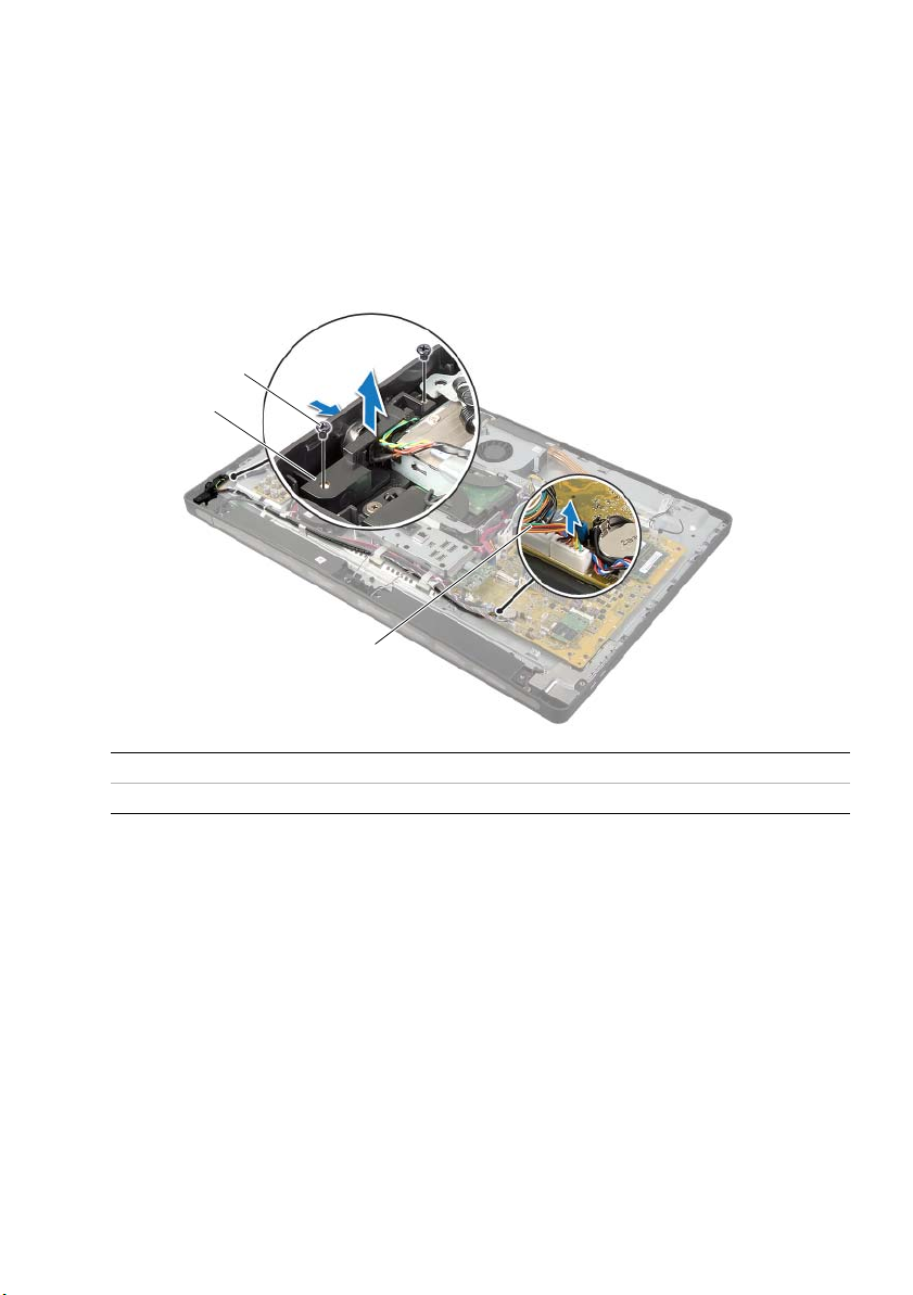
Procedure
1 Disconnect the power-button cable from the system board.
2 Note the routing of the power-button cable and remove the power-button cable
from its routing guides.
3 Remove the screws that secure the power-button assembly to the display bezel.
4 Press the power button inward to release it from the slot on the display bezel and
then gently lift the power-button assembly off the display bezel.
3
2
1
1 power-button cable 2 power-button assembly
3screws (2)
Removing the Power-Button Assembly | 75
Page 76

Replacing the Power-Button Assembly
WARNING: Before working inside your computer, read the safety information
that shipped with your computer and follow the steps in "Before You Begin" on
page 11. After working inside your computer, follow the instructions in "After
Working Inside Your Computer" on page 13. For additional safety best practices
information, see the Regulatory Compliance Homepage at
dell.com/regulatory_compliance.
Procedure
1 Slide the power button into the slot on the display bezel and place the
power-button assembly on the display bezel.
2 Align the screw holes on the power-button assembly with the screws holes on
the display bezel.
3 Replace the screws that secure the power-button assembly to the display bezel.
4 Route the power-button cable through the routing guides and connect the
power-button cable to the system board.
Postrequisites
1 Replace the inner frame. See "Replacing the Inner Frame" on page 50.
2 Replace the system-board shield. See "Replacing the System-Board Shield" on
page 32.
3 Replace the stand. See "Replacing the Stand" on page 22.
4 Replace the trim cover. See "Replacing the Trim Cover" on page 20.
5 Replace the back cover. See "Replacing the Back Cover" on page 18.
6 Follow the instructions in "After Working Inside Your Computer" on page 13.
76 | Replacing the Power-Button Assembly
Page 77

Removing the System Board
WARNING: Before working inside your computer, read the safety information
that shipped with your computer and follow the steps in "Before You Begin" on
page 11. After working inside your computer, follow the instructions in "After
Working Inside Your Computer" on page 13. For additional safety best practices
information, see the Regulatory Compliance Homepage at
dell.com/regulatory_compliance.
NOTE: Your computer’s Service Tag is stored in the system board. You must enter
the Service Tag in system setup after you replace the system board.
NOTE: Before disconnecting the cables from the system board, note the location
of the connectors so that you can reconnect them correctly after you replace the
system board.
Prerequisites
1 Remove the back cover. See "Removing the Back Cover" on page 17.
2 Remove the trim cover. See "Removing the Trim Cover" on page 19.
3 Remove the stand. See "Removing the Stand" on page 21.
4 Remove the I/O panel. See "Removing the I/O Panel" on page 40.
5 Remove the system-board shield. See "Removing the System-Board Shield" on
page 31.
6 Follow the instructions from step 1 to step 5 in "Removing the I/O-Board" on
page 67.
7 Remove the memory module(s). See "Removing the Memory Module(s)" on
page 28.
8 Remove the mSATA mini-card. See "Removing the mSATA Mini-Card" on page 47.
9 Remove the wireless mini-card. See "Removing the Wireless Mini-Card" on
page 44.
10 Remove the processor heat-sink. See "Removing the Processor Heat-Sink" on
page 53.
11 Remove the processor. See "Removing the Processor" on page 55.
Removing the System Board | 77
Page 78

Procedure
1 Disconnect all the cables connected to the system board.
NOTE: For information on the location of the connectors, see "System-Board
Components" on page 15.
2 Remove the screws that secure the system board to the middle cover.
3 Lift the system board off the middle cover.
2
1 screws (11) 2 system board
1
78 | Removing the System Board
Page 79

Replacing the System Board
WARNING: Before working inside your computer, read the safety information
that shipped with your computer and follow the steps in "Before You Begin" on
page 11. After working inside your computer, follow the instructions in "After
Working Inside Your Computer" on page 13. For additional safety best practices
information, see the Regulatory Compliance Homepage at
dell.com/regulatory_compliance.
NOTE: Your computer’s Service Tag is stored in the system board. You must enter
the Service Tag in the system setup after you replace the system board.
Procedure
1 Align the screw holes on the system board with the screw holes on the
middle cover.
2 Replace the screws that secure the system board to the middle cover.
3 Connect the disconnected cables to the system board.
Postrequisites
1 Replace the processor. See "Replacing the Processor" on page 56.
2 Replace the processor heat-sink. See "Replacing the Processor Heat-Sink" on
page 54.
3 Replace the wireless mini-card. See "Replacing the Wireless Mini-Card" on page 46.
4 Replace the mSATA mini-card. See "Replacing the mSATA Mini-Card" on page 48.
5 Replace the memory modules. See "Replacing the Memory Module(s)" on page 30.
6 Follow the instructions from step 3 to step 7 in "Replacing the I/O Board" on
page 70.
7 Replace the system-board shield. See "Replacing the System-Board Shield" on
page 32.
8 Replace the I/O panel. See "Replacing the I/O Panel" on page 41.
9 Replace the stand. See "Replacing the Stand" on page 22.
10 Replace the trim cover. See "Replacing the Trim Cover" on page 20.
11 Replace the back cover. See "Replacing the Back Cover" on page 18.
12 Follow the instructions in "After Working Inside Your Computer" on page 13.
Replacing the System Board | 79
Page 80

Entering the Service Tag in system setup
1 Turn on the computer.
2 Press <F2> during POST to enter the system setup program.
3 Navigate to the Main tab and enter the Service Tag in the Service Tag Input field.
See "System Setup Options" on page 105.
80 | Replacing the System Board
Page 81

Removing the Side I/O-Board
WARNING: Before working inside your computer, read the safety information
that shipped with your computer and follow the steps in "Before You Begin" on
page 11. After working inside your computer, follow the instructions in "After
Working Inside Your Computer" on page 13. For additional safety best practices
information, see the Regulatory Compliance Homepage at
dell.com/regulatory_compliance.
Prerequisites
1 Remove the back cover. See "Removing the Back Cover" on page 17.
2 Remove the trim cover. See "Removing the Trim Cover" on page 19.
3 Remove the stand. See "Removing the Stand" on page 21.
4 Remove the I/O panel. See "Removing the I/O Panel" on page 40.
5 Remove the system-board shield. See "Removing the System-Board Shield" on
page 31.
6 Remove the inner frame. See "Removing the Inner Frame" on page 49.
7 Follow the instructions from step 1 to step 5 in "Removing the I/O-Board" on
page 67.
8 Disconnect the antenna cables from the wireless mini-card. See "Removing the
Wireless Mini-Card" on page 44.
9 Remove the processor heat-sink. See "Removing the Processor Heat-Sink" on
page 53.
10 Follow the instructions from step 1 to step 3 in "Removing the System Board" on
page 77.
Removing the Side I/O-Board | 81
Page 82

Procedure
1
1 Remove the screws that secure the side I/O-board shield to the display bezel.
2 Lift the side I/O-board shield off the side I/O board.
1
1 grounding cable 2 side I/O-board
3 screws (2) 4 side-I/O-board shield
3 Gently lift the side I/O-board starting from the inner edge and then ease the ports
on the side I/O-board out of the slots on the display bezel.
2
3
4
1 side I/O-board
82 | Removing the Side I/O-Board
Page 83

Replacing the Side-I/O Board
WARNING: Before working inside your computer, read the safety information
that shipped with your computer and follow the steps in "Before You Begin" on
page 11. After working inside your computer, follow the instructions in "After
Working Inside Your Computer" on page 13. For additional safety best practices
information, see the Regulatory Compliance Homepage at
dell.com/regulatory_compliance.
Procedure
1 Slide the ports on the side I/O-board into the slots on the display bezel and align
the screw holes on the side I/O-board with the screw holes on the display bezel.
2 Align the screw holes on the side I/O-board shield with the screw holes on the
display bezel and place the side I/O-board shield on the side-I/O board.
3 Replace the screws that secure the side I/O-board shield to display bezel.
NOTE: Ensure to secure the grounding cable with the same screw that secures
the side I/O-shield to the display bezel.
Postrequisites
1 Follow the instructions from step 1 to step 3 in "Replacing the System Board" on
page 79.
2 Replace the processor heat-sink. See "Replacing the Processor Heat-Sink" on
page 54.
3 Connect the antenna cables to the wireless mini-card. See "Replacing the Wireless
Mini-Card" on page 46.
4 Follow the instructions from step 3 to step 7 in "Replacing the I/O Board" on
page 70.
5 Replace the inner frame. See "Replacing the Inner Frame" on page 50.
6 Replace the system-board shield. See "Replacing the System-Board Shield" on
page 32.
7 Replace the I/O panel. See "Replacing the I/O Panel" on page 41.
8 Replace the stand. See "Replacing the Stand" on page 22.
9 Replace the trim cover. See "Replacing the Trim Cover" on page 20.
10 Replace the back cover. See "Replacing the Back Cover" on page 18.
11 Follow the instructions in "After Working Inside Your Computer" on page 13.
Replacing the Side-I/O Board | 83
Page 84

Removing the Middle Cover
WARNING: Before working inside your computer, read the safety information
that shipped with your computer and follow the steps in "Before You Begin" on
page 11. After working inside your computer, follow the instructions in "After
Working Inside Your Computer" on page 13. For additional safety best practices
information, see the Regulatory Compliance Homepage at
dell.com/regulatory_compliance.
WARNING: The middle cover is heavy when the components are attached to it.
It is recommended that two people remove and replace the middle cover while
the components are attached to it.
Prerequisites
1 Remove the back cover. See "Removing the Back Cover" on page 17.
2 Remove the trim cover. See "Removing the Trim Cover" on page 19.
3 Remove the stand. See "Removing the Stand" on page 21.
4 Follow the instructions from step 1 to step 2 in "Removing the Hard Drive" on
page 35.
5 Remove the hard-drive cage. See"Removing the Hard-Drive Cage" on page 38.
6 Follow the instructions from step 1 to step 2 in "Removing the Optical Drive" on
page 25.
7 Remove the I/O panel. See "Removing the I/O Panel" on page 40.
8 Remove the system-board shield. See "Removing the System-Board Shield" on
page 31.
9 Remove the inner frame. See "Removing the Inner Frame" on page 49.
10 Follow the instructions from step 1 to step 5 in "Removing the I/O-Board" on
page 67.
11 Remove the processor heat-sink fan. See "Removing the Processor Heat-Sink Fan"
on page 51.
12 Remove the processor heat-sink. See "Removing the Processor Heat-Sink" on
page 53.
13 Remove the power-supply fan. See "Removing the Power-Supply Fan" on page 33.
14 Remove the power-supply unit. See "Removing the Power-Supply Unit" on page 58.
15 Remove the converter board. See "Removing the Converter Board" on page 23.
16 Follow the instructions from step 1 to step 3 in "Removing the System Board" on
page 77.
84 | Removing the Middle Cover
Page 85

Procedure
1 Remove the screws that secure the side I/O-board shield to the chassis.
2 Lift the side I/O-board shield off the side I/O-board.
3 Remove the screw that secures the grounding cable to the middle cover.
4 Press the securing clips and disconnect the LVDS cables from the display assembly.
5 Disconnect the touchscreen cable from the display assembly.
4
3
2
1
1 I/O-board shield 2 screws (2)
3 grounding cable 4 grounding-cable screw
5 LVDS cable (LVDS1) 6 securing clips (4)
7 LVDS cable (LVDS2) 8 touchscreen cable
5
6
7
8
Removing the Middle Cover | 85
Page 86

6 Remove the screws that secure the middle frame to the display bezel.
1
2
7 Remove all the cables from their routing guides on the middle cover.
8 Lift the middle cover off the display.
1 screws (2) 2 middle cover
86 | Removing the Middle Cover
Page 87

Replacing the Middle Cover
WARNING: Before working inside your computer, read the safety information
that shipped with your computer and follow the steps in "Before You Begin" on
page 11. After working inside your computer, follow the instructions in "After
Working Inside Your Computer" on page 13. For additional safety best practices
information, see the Regulatory Compliance Homepage at
dell.com/regulatory_compliance.
Procedure
1 Align the screw holes on the middle cover with the screw holes on the
display bezel.
2 Replace the screws that secure the middle cover to the display bezel.
3 Route all the cables through their routing guides on the middle frame.
4 Connect the LVDS and touchscreen cables to the display assembly.
5 Replace the screw that secures the grounding cable to the middle cover.
6 Align the screw holes on the side I/O-board shield with the screw holes on
the display bezel and place the side I/O-board shield on the side-I/O board.
7 Replace the screws that secure the side I/O-board shield to display bezel.
Replacing the Middle Cover | 87
Page 88

Postrequisites
1 Follow the instructions from step 1 to step 3 in "Replacing the System Board" on
page 79.
2 Replace the converter board. See "Replacing the Converter Board" on page 24.
3 Replace the power-supply unit. See "Replacing the Power-Supply Unit" on page 60.
4 Replace the power-supply fan. See "Replacing the Power-Supply Fan" on page 34.
5 Replace the processor heat-sink. See "Replacing the Processor Heat-Sink" on
page 54.
6 Replace the processor heat-sink fan. See "Replacing the Processor Heat-Sink Fan"
on page 52.
7 Follow the instructions from step 3 to step 7 in "Replacing the I/O Board" on
page 70.
8 Replace the inner frame. See "Replacing the Inner Frame" on page 50.
9 Replace the system-board shield. See "Replacing the System-Board Shield" on
page 32.
10 Replace the I/O panel. See "Replacing the I/O Panel" on page 41.
11 Follow the instructions from step 2 to step 4 in "Replacing the Optical Drive" on
page 27.
12 Replace the hard-drive cage. See"Replacing the Hard-Drive Cage" on page 39.
13 Follow the instructions from step 2 to step 3 in "Replacing the Hard Drive" on
page 37.
14 Replace the stand. See "Replacing the Stand" on page 22.
15 Replace the trim cover. See "Replacing the Trim Cover" on page 20.
16 Replace the back cover. See "Replacing the Back Cover" on page 18.
17 Follow the instructions in "After Working Inside Your Computer" on page 13.
88 | Replacing the Middle Cover
Page 89

Removing the Display Panel
WARNING: Before working inside your computer, read the safety information
that shipped with your computer and follow the steps in "Before You Begin" on
page 11. After working inside your computer, follow the instructions in "After
Working Inside Your Computer" on page 13. For additional safety best practices
information, see the Regulatory Compliance Homepage at
dell.com/regulatory_compliance.
Prerequisites
1 Remove the back cover. See "Removing the Back Cover" on page 17.
2 Remove the trim cover. See "Removing the Trim Cover" on page 19.
3 Remove the stand. See "Removing the Stand" on page 21.
4 Remove the I/O panel. See "Removing the I/O Panel" on page 40.
5 Remove the system-board shield. See "Removing the System-Board Shield" on
page 31.
6 Remove the inner frame. See "Removing the Inner Frame" on page 49.
7 Remove the processor heat-sink fan. See "Removing the Processor Heat-Sink Fan"
on page 51.
Removing the Display Panel | 89
Page 90

Procedure
1 Disconnect the power-button cable, speakers cable, camera cable, input
source/display-settings controls cable, wireless keyboard/mouse receiver cable,
LVDS cables, and touchscreen cable from the system board and remove the cables
from their routing guides.
2 Disconnect the antenna cables from the wireless mini-card and remove the
antenna cables from their routing guides.
7
6
5
8
4
9
3
2
1
1 speakers cable 2 input source/display-settings controls
3 wireless keyboard/mouse receiver cable 4 power-button cable
5 LVDS cable (LVDS1) 6 LVDS cable (LVDS2)
7 touchscreen cable 8 antenna cables (2)
9camera cable
cable
3 Remove the screw that secures the grounding cable to the processor cooling vents.
90 | Removing the Display Panel
Page 91

4 Remove the screw that secures the grounding cable from the right-speaker mesh
5
6
1
3
4
2
to the middle cover.
5 Remove the screws that secure the system board to the side I/O-board.
6 Remove the screws that secure the side I/O-board shield to the display bezel
and remove the side I/O-board shield.
1 side I/O-board shield 2 screw (4)
3 grounding cable 4 grounding-cable screw
5 processor cooling-vents grounding cable 6 grounding-cable screw
Removing the Display Panel | 91
Page 92
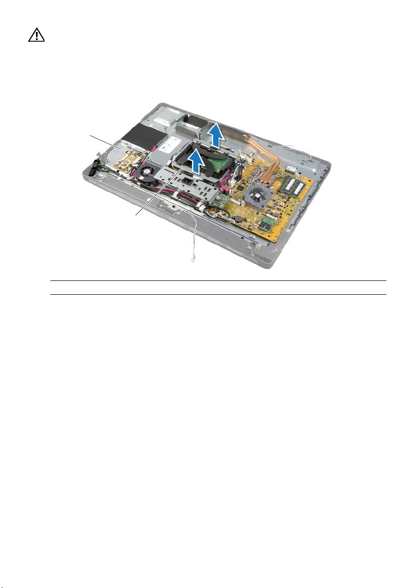
WARNING: The middle cover is heavy when the components are attached to it.
It is recommended that two people remove and replace the middle cover while
the components are attached to it.
7 Using the hard-drive cage, gently lift the middle-cover assembly along with the
components and ease the cables out of the slots.
2
1
1 hard-drive cage 2 middle-cover assembly
92 | Removing the Display Panel
Page 93

8 Gently lift the side I/O-board starting from the inner edge and then ease the ports
on the side I/O-board out of the slots on the display bezel.
2
1
1 display assembly 2 side I/O-board
Removing the Display Panel | 93
Page 94

9 Pull the tab and disconnect the ribbon cables from the display assembly.
10 Peel off the tapes securing the ribbon cables to the display assembly.
11 Remove the screws that secure the display assembly to the display bezel.
12 Lift the display assembly from the chassis.
3
4
1
2
5
1 tabs (4) 2 ribbon cables (4)
3 tape 4 screws (6)
5 display assembly
94 | Removing the Display Panel
Page 95

13 Remove the screws that secure the display brackets to the display panel and
remove the display brackets.
3
2
1 screws (4) 2 display brackets (2)
3 display panel
1
Removing the Display Panel | 95
Page 96

Replacing the Display Panel
WARNING: Before working inside your computer, read the safety information
that shipped with your computer and follow the steps in "Before You Begin" on
page 11. After working inside your computer, follow the instructions in "After
Working Inside Your Computer" on page 13. For additional safety best practices
information, see the Regulatory Compliance Homepage at
dell.com/regulatory_compliance.
WARNING: The middle cover is heavy when the components are attached to it.
It is recommended that two people remove and replace the middle cover while
the components are attached to it.
Procedure
1 Align the screw holes on the display brackets with the screw holes on the
display panel.
2 Replace the screws that secure the display brackets to the display panel.
3 Align the screw holes on the display assembly with the screws holes on the
display bezel and gently place the display assembly over the display bezel.
NOTE: Ensure that no cables are placed under the display assembly.
4 Replace the screws that secure the display assembly to the display bezel.
5 Insert the ribbon cables into their connectors and press the tab to secure
the cables.
6 Adhere the tapes that secure the ribbon cables to the display assembly.
7 Slide the ports on the side-I/O board into the slot on the display bezel and align the
screw holes on the side-I/O board with the screw holes on the display bezel.
WARNING: The middle cover is heavy when the components are attached to it.
It is recommended that two people remove and replace the middle cover while
the components are attached to it.
8 Using the hard-drive cage, align the bottom of the middle-cover assembly with the
display bezel and lower the middle-cover assembly into the display bezel.
9 Route the LVDS and touchscreen cables through the slots in the middle cover.
10 Place the middle-cover assembly into the display bezel.
NOTE: Ensure that all cables are routed through their routing guides and
no cables are placed under the middle cover.
11 Align the screw holes on the middle cover with the screw holes on the
display bezel.
12 Replace the screws that secure the middle-cover assembly to the display bezel.
96 | Replacing the Display Panel
Page 97

13 Align the screw holes on the side I/O-board shield with the screw holes on the
chassis and replace the screws that secure the side I/O-board shield to the
display bezel.
NOTE: Ensure that you also secure the grounding cable with the same screw
that secures the side I/O-board shield to the display bezel.
14 Route the power-button, speakers, camera, input source/display-settings controls,
wireless keyboard/mouse receiver, and touchscreen cables through their routing
guides and connect the cables to the system board.
15 Route the wireless-antenna cables through their routing guides and connect the
antenna cables to the wireless mini-card.
16 Replace the screw that secures the grounding cable to the processor
cooling-vents.
17 Replace the screw that secures the grounding cable from the right-speaker mesh
to the middle cover.
Postrequisites
1 Replace the processor heat-sink fan. See "Replacing the Processor Heat-Sink Fan"
on page 52.
2 Replace the inner frame. See "Replacing the Inner Frame" on page 50.
3 Replace the system-board shield. See "Replacing the System-Board Shield" on
page 32.
4 Replace the I/O panel. See "Replacing the I/O Panel" on page 41.
5 Replace the stand. See "Replacing the Stand" on page 22.
6 Replace the trim cover. See "Replacing the Trim Cover" on page 20.
7 Replace the back cover. See "Replacing the Back Cover" on page 18.
8 Follow the instructions in "After Working Inside Your Computer" on page 13.
Replacing the Display Panel | 97
Page 98

Removing the Camera Module
WARNING: Before working inside your computer, read the safety information
that shipped with your computer and follow the steps in "Before You Begin" on
page 11. After working inside your computer, follow the instructions in "After
Working Inside Your Computer" on page 13. For additional safety best practices
information, see the Regulatory Compliance Homepage at
dell.com/regulatory_compliance.
Prerequisites
1 Remove the back cover. See "Removing the Back Cover" on page 17.
2 Remove the trim cover. See "Removing the Trim Cover" on page 19.
3 Remove the stand. See "Removing the Stand" on page 21.
4 Remove the I/O panel. See "Removing the I/O Panel" on page 40.
5 Remove the system-board shield. See "Removing the System-Board Shield" on
page 31.
6 Remove the inner frame. See "Removing the Inner Frame" on page 49.
7 Remove the processor heat-sink fan. See "Removing the Processor Heat-Sink Fan"
on page 51.
8 Follow the instructions from step 1 to step 12 in "Removing the Display Panel" on
page 89.
98 | Removing the Camera Module
Page 99

Procedure
1 Remove the screws that secure the camera assembly to the chassis.
2 Gently lift the camera assembly and disconnect the camera cable from the
camera assembly.
3
2
1
1 camera cable 2 camera assembly
3screws (2)
3 Release the tabs that secure the camera module to the camera bracket and remove
the camera module.
3
2
1
1 camera bracket 2 tabs (2)
3camera module
Removing the Camera Module | 99
Page 100

Replacing the Camera Module
WARNING: Before working inside your computer, read the safety information
that shipped with your computer and follow the steps in "Before You Begin" on
page 11. After working inside your computer, follow the instructions in "After
Working Inside Your Computer" on page 13. For additional safety best practices
information, see the Regulatory Compliance Homepage at
dell.com/regulatory_compliance.
Procedure
1 Align the tabs on the camera module with the slots on the camera assembly and
snap the camera module into place.
2 Connect the camera cable to the camera assembly and place the camera on the
display bezel.
3 Replace the screws that secure the camera assembly to the display bezel.
Postrequisites
1 Follow the instructions from step 3 to step 17 in "Replacing the Display Panel" on
page 96.
2 Replace the processor heat-sink fan. See "Replacing the Processor Heat-Sink Fan"
on page 52.
3 Replace the inner frame. See "Replacing the Inner Frame" on page 50.
4 Replace the system-board shield. See "Replacing the System-Board Shield" on
page 32.
5 Replace the I/O panel. See "Replacing the I/O Panel" on page 41.
6 Replace the stand. See "Replacing the Stand" on page 22.
7 Replace the trim cover. See "Replacing the Trim Cover" on page 20.
8 Replace the back cover. See "Replacing the Back Cover" on page 18.
9 Follow the instructions in "After Working Inside Your Computer" on page 13.
100 | Replacing the Camera Module
 Loading...