

Page 1
'HOO'LPHQVLRQ;36+6\VWHP
5()(5(1&(*8,'(
®
0RGHO006
Page 2

Page 3

'HOO'LPHQVLRQ;36+6\VWHP
5()(5(1&(*8,'(
®
Page 4

Information in this document is subject to change without notice.
1997 Dell Computer Corporation. All r ig hts reserved.
Reproduction in any manner whatsoever without the written permission of Dell Computer Corporati on is strictly forbidden.
Trademarks used in this text: Dell, the DELL logo, and OptiPlex are registered tradem a rks , Dell Dimension is a trademar k, and DellWare is a
registered service mark of Dell Computer Corporation; Intel is a registered trademark and MMX is a trademark of Intel Corporation; Microsoft,
Windows, and
Windows NT are registered trademarks of Mi crosoft Corporation.
Other trademarks and t rade names may be used in this document to refer to either the ent itie s claiming the marks and nam es or th eir products.
Dell Computer Corporation disclaims any pro prietary interest in trademarks and trade names other th an i ts own.
January 1997 P/N 84974
Page 5

Safety Instructions
U
se the following safety guidelines to he lp protect
your computer system from potential damage and to
ensure your own personal safety.
W
hen Using Your Computer
System
As you use your computer system, observe the fo llow ing
safety guidelines:
•
To help avoid damaging your computer, be sure the
voltage selection switch on the power supply is set to
match the alternating current (AC) power available
at your location:
— 115 volts (V)/60 hertz (Hz) in most of North and
South America and some Far Eastern countries
such as Japan, South Korea, and Taiwan
— 230 V/50 Hz in most of Europe, the Middle
East, and the Far East
Also be sure your monitor and attached peripherals
are electrically rated to operate with the AC power
available in your location.
•
To help avoid possible damage to the system board,
wait 5 seconds after turning off the system before
removing a component from the system bo ard or d isconnecting a peripheral device from the computer.
•
To help prevent electric shock, plug the computer
and peripheral power cables into properly grounded
power sources. These cables are equipped with
3-prong plugs to help ensure proper grounding. Do
not use adapter plugs or remove the groundin g prong
from a cable. If you must use an extension cable, use
a 3-wire cable with properly grounded plugs.
•
To help protect your computer system from sudden,
transient increases and decreases in electrical power,
use a surge suppressor, line conditioner, or uninterruptible power su ppl y.
•
Be sure nothing r ests on your compu t er system’s
cables and that the cables are not located where they
can be stepped on or tripped over.
•
Do not spill food or liquids on your computer. If the
computer gets we t, consult your Diagnostics and
Troubleshooting Guide.
•
Do not push any objects into the openings of your
computer. Doing so can cause fire or electric shock
by shorting out interior components.
•
Keep your computer away from radiators and heat
sources. Also, do not block cooling vents. Avoid
placing loose papers underneath yo ur computer; do
not place your computer in a closed-in wall unit or
on a bed, sofa , or rug.
E
rgonomic Computing Habits
WARNING: Improper or prolonged keyboard use
may result in injury.
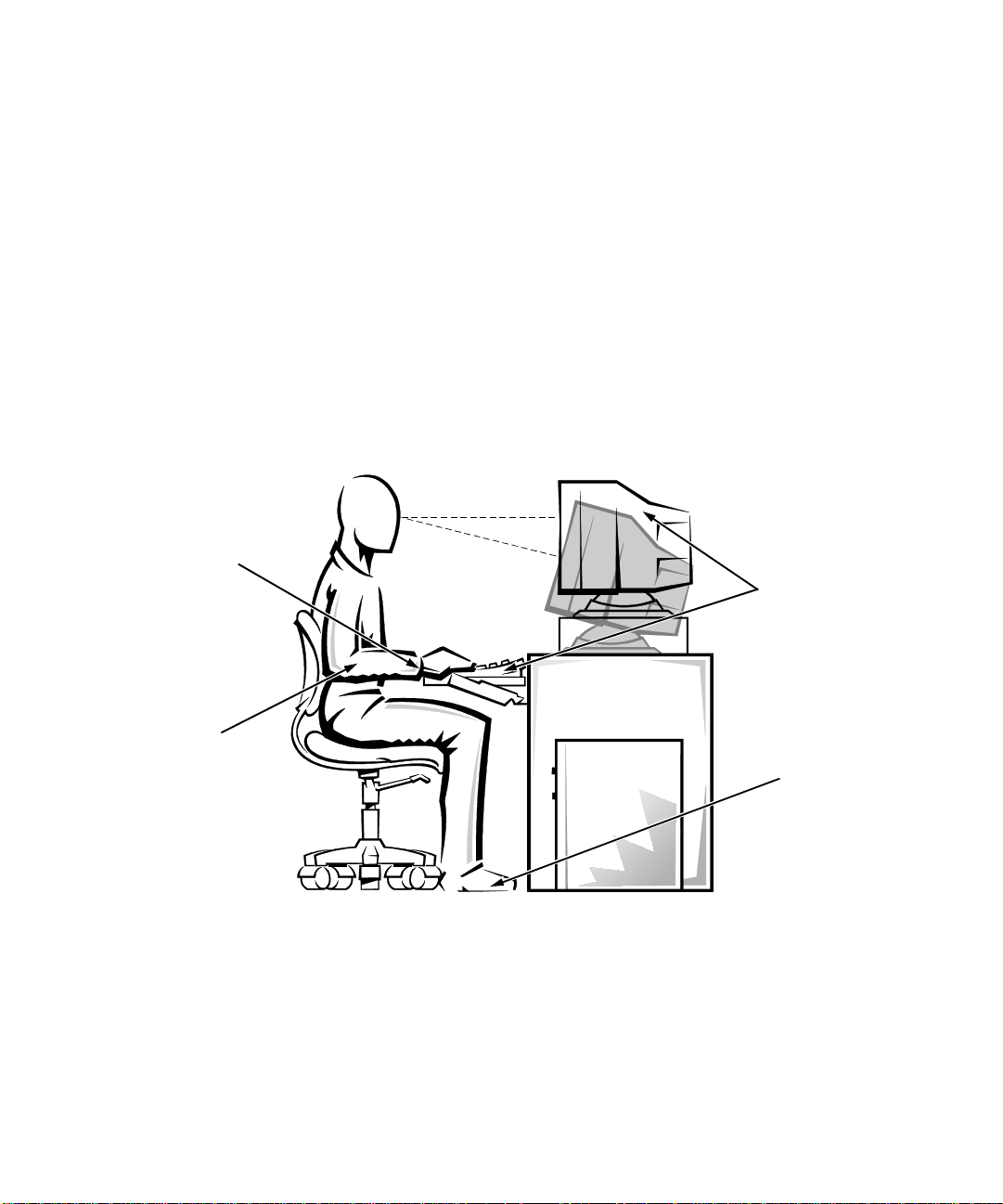
For comfort and efficiency, observe the following ergonomic guidelines when setting u p and using your
computer system:
•
Position your system so that the monitor and keyboard are directly in front of you as you work.
Special shelves are available (from Dell and other
sources) to help you correctly po sition your
keyboard.
v
Page 6
•
Set the monitor at a comfortable viewing distance
(usually 510 to 610 millimeters [20 to 24 inches]
from your eyes).
•
Make sure the monitor screen is at eye level or
slightly lower when you are sitting in front of the
monitor.
•
Adjust the tilt of the monitor, its contrast and brightness settings, and the lighting around you (such as
overhead lights, desk lamps, and the curtains or
blinds on nearby windows) to minimize reflections
and glare on the monitor screen.
•
Use a chair that provides good lower back support.
•
Keep your forearms horizontal with your wrists in a
neutral, comfortable position while using the keyboard or mouse.
monitor screen at or below eye level
wrists relaxed and flat
•
Always leave space to rest your hands while using
the keyboard or mouse.
•
Let your upper arms hang naturally at your sides.
•
Sit erect, with your feet resting on the floor and your
thighs level.
•
When sitting, make sure the weight of your legs is on
your feet and not on the front of your chair seat.
Adjust your chair’s height or use a footrest, if necessary, to maintain proper posture.
•
Vary y our wor k activ iti es. Try to or gan ize y our work
so that you do not have to type for extended periods
of time. When you stop typing, try to do things that
use both hands.
monitor and keyboard
positioned directly
in front of user
arms at desk level
vi
feet flat on the floor
Page 7

W
hen Working Inside Your
Computer
Before you remove the computer cover, perform the following steps in the sequence indicated.
Handle components and cards with care. Don’t touch
•
the components or contacts on a card. Hold a card by
its edges or by its metal mounting bracket. Hold a
component such as a microprocessor chip by its
edges, not by its pins.
CAUTIONS: Do not attempt to service the computer system yourself, except as explained in this
guide and elsewhere in Dell documentation. Always
follow installation and service instructions closely.
To help avoid possible damage to the system board,
wait 5 seconds after turning off the system before
removing a component from the system board or
disconnecting a peripheral device from the
computer.
1. Turn off your computer and any peripherals.
2. Disconnect your computer and peripherals from
their power sources. Also, disconnect any telephone or telecommunication lines from the
computer.
Doing so reduces the potential for personal injury or
shock.
3. Touch an unpainted metal surface on the chassis,
such as the metal around the card-slot openings at
the back of the computer, before touching anything inside your computer.
While you work, periodically touch an unpainted
metal surface on the computer chassis to dissipate
any static electricity that might harm internal
components.
In addition, take note of these safety guidelines when
appropriate:
When you disconnect a cable, pull on its connector
•
or on its strain-relief loop, not on the cable itself.
Some cables have a connector with locking tabs; if
you are disconnecting this type of cable, press in on
the locking tabs before disconnecting the cable. As
you pull connectors apart, keep them evenly aligned
to avoid bending any connector pins. Also, before
you connect a cable, make sure both connectors are
correctly oriented and aligned.
Protecting Against Electrostatic Discharge
Static electricity can harm delicate components inside
your computer . To prevent static damage, di schar ge static
electricity from your body before you touch any of your
computer’s electronic components, such as the microprocessor. You can do so by touching an unpainted metal
surface on the computer chassis.
As you continue to work inside the computer, periodically touch an unpainted metal surface to remove any
static charge your body may have accumulated.
In addition to the preceding precautions, you can also
take the following steps to prevent damage from electrostatic discharge (ESD):
When unpacking a static-sensitive component from
•
its shipping carton, do not remove the component
from the antistatic packing material until you are
ready to install the component in your computer. Just
before unwrapping the antistatic packaging, be sure
to discharge static electricity from your body.
When transporting a sensitive component, first place
•
it in an antistatic container or packaging.
Handle all sensitive components in a static-safe area.
•
If possible, use antistatic floor pads and workbench
pads.
The following caution may appear throughout this document to remind you of these precautions:
CAUTION: See “Protecting Against Electrostatic
Discharge” in the safety instructions at the front of
this guide.
vii
Page 8

viii
Page 9

Preface
A
bout This Guide
This guide is intended for anyone who uses a Dell
Dimension XPS H233 computer system. It can be used
by both first-time and experienced computer users who
want to learn about the computer. The chapters and
appendixes are summarized as follows:
•
Everyone should read Chapter 1, “Introduction,” for
an overview of system features, instructions on
accessing the online System User’s Guide, and infor-
mation on getting help if you need it.
•
Everyone should read Chapter 2, “Using Configur ation Software,” to familiarize themselves with the
system setup program and ISA Configuration Utility.
Users who want to make configuration changes to
their systems or who want to use the password features can get full descriptions of these programs in
the online System User’s Guide.
•
Chapter 3, “Inside Your Computer,” is intended for
users who need to remove the computer cover to
access internal components. The procedures for
installing any upgrades are included in the online
System User’s Guide.
•
Appendix A, “Beep Codes and System Messages,”
documents status and error messages generated by
the computer’s basic input/output system (BIOS)
and the ISA Configuration Utility. Included are possible causes and corrective actions.
•
Appendix B, “Regulatory Notices,” is for users who
are interested in which regulatory agencies have
tested and approved the Dell Dimension XPS H233
system.
•
Appendix C, “Warranties and Return Policy,”
describes the warranty for your Dell system and the
“total satisfaction” return policy.
W
arranty and Return Policy
Information
Dell Computer Corporation (“Dell”) manufactures its
hardware products from parts and compon ents that are
new or equivalent to new in accordance with industrystandard practices. For information about the Dell
warranty for your system, see Appendix C, “Warranties
and Return Policy.”
O
ther Documents You May Need
Besides this Referen ce Guide, t h e following documentation is included with your sy stem:
•
The Getting Started sheet provides the steps for setting up your computer system.
•
The Windows-based online System User’ s Guide contains important information about your computer
system, including descriptions of system features
and software, instructions for attaching devices to
the connectors on your computer’s back panel, and
procedures for performing various upgrades such as
installing additional memory o r dr ives.
•
The Diagnostics and Troubleshooti ng Guide includ es
troubleshooting procedures and instructions for
using the diskette-based diagnostics to test your
computer system.
ix
Page 10

You may also have one or more of the following
documents.
NOTE: Documentation updates are sometimes included
with your system to describe changes to your system or
software. Always read these updates before consultin g
any other documentation because the updates often contain the latest information.
Operating system documentation is included if you
•
ordered your operating system software from Dell.
This documentation describes how to install (if necessary), configure, and use your operating system
software.
Video card documentation from the card manufac-
•
turer describes the video drivers included with the
system. Only users who want to change the default
video driver or reinstall t he video driv er need to r ead
this documentation in detail.
Documentation is included with any options you
•
purchase separately from your system. This documentation includes information that you need if you
plan to configure and install these options in your
Dell computer. Installation instructions for the
options are included in the online System User’s
Guide.
The Dell Service and Support Po licies is an online
•
reference to Dell’s service and support policies,
guarantees, and warranties. It applies to the United
States only. The Dell Service and Support Policies is
located in the Dell Accessories group or folder.
Technical information files—sometimes called
•
“readme” files—may be installed on your hard-disk
drive to provide last-minute updates about technical
changes to your system or advanced technical reference material intended for experienced users or
technicians.
N
otational Conventions
The following subsections describe notational conventions used in this document.
Warnings, Cautions, and Notes
Throughout this guide, there may be blocks of text
printed in bold type within boxes or in italic type. These
blocks are warnings, cautions, and notes, and they are
used as follows:
WARNING: A WARNING indicates the potential
for bodily harm and tells you how to avoid the
problem.
CAUTION: A CAUTION indicates either potential damage to ha rdware or loss of data and tells
you how to avoid the problem.
NOTE: A NOTE indicates important information that
helps you make better use of your computer system.
Typographical Conventions
The following list defines (where appropriate) and illustrates typographical conventions used as visual cues for
specific elements of text throughout this document:
Keycaps, the labeling that appears on the keys on a
•
keyboard, are enclosed in angle brackets.
Example: <Enter>
Key combinations are series of keys to be pressed
•
simultaneously (unless otherwise indicated) to perform a single function.
Example: <Ctrl><Alt><Del>
Commands presented in lowercase bold are for refer-
•
ence purposes only and are not intended to be typed
when referenced.
Example: “Use the format command to . . . .”
In contrast, commands presented in th e Courier New
font are part of an instruction and intended to be
typed.
Example: “Type
in drive A.”
format a:
to format the diskette
x
Page 11

•
Filenames and directory names are presented in
lowercase bold.
Examples: autoexec.bat and c:\windows
•
Command lines consist of a command and may
include one or more of the command’s possible
parameters. Command lines are presented in the
Courier New font.
Example:
del c:\myfile.doc
•
Screen text is text that appears on the screen of your
monitor or display. It can be a system message, for
example, or it can be text that you are instructed to
type as part of a command (referred to as a comman d
line). Screen text is presented in the Courier New
font.
Example: The message
available
Example: “Type
•
Variables are placeholders for which you subs titute a
value. They are presented in italics.
Example: SIMMn (where n represents the SIMM socket
designation)
appears on your screen.
No boot device
md c:\dos
and press <Enter>.”
xi
Page 12

xii
Page 13

Contents
Chapter 1
Introduction . . . . . . . . . . . . . . . . . . . . . . . . . . . . . . . . . . . . . . . . . . . 1-1
System Features. . . . . . . . . . . . . . . . . . . . . . . . . . . . . . . . . . . . . . . . . . . . . . . . . . . . . . 1-1
Accessing Online Documentation. . . . . . . . . . . . . . . . . . . . . . . . . . . . . . . . . . . . . . . . 1-2
Getting Help . . . . . . . . . . . . . . . . . . . . . . . . . . . . . . . . . . . . . . . . . . . . . . . . . . . . . . . . 1-3
Chapter 2
Using Configuration Software . . . . . . . . . . . . . . . . . . . . . . . . . . . . 2-1
System Setup Program . . . . . . . . . . . . . . . . . . . . . . . . . . . . . . . . . . . . . . . . . . . . . . . . 2-1
Entering the System Setup Program . . . . . . . . . . . . . . . . . . . . . . . . . . . . . . . . . . . . . . 2-1
System Setup Screens . . . . . . . . . . . . . . . . . . . . . . . . . . . . . . . . . . . . . . . . . . . . . . . . . 2-2
Using the System Setup Program . . . . . . . . . . . . . . . . . . . . . . . . . . . . . . . . . . . . . . . . 2-2
Responding to Error Messages . . . . . . . . . . . . . . . . . . . . . . . . . . . . . . . . . . . . . . . . . . 2-3
Disabling a Forgotten Password . . . . . . . . . . . . . . . . . . . . . . . . . . . . . . . . . . . . . . . . . 2-3
ISA Configuration Utility . . . . . . . . . . . . . . . . . . . . . . . . . . . . . . . . . . . . . . . . . . . . . . 2-4
When to Run the ISA Configuration Utility . . . . . . . . . . . . . . . . . . . . . . . . . . . . 2-4
Quick Start . . . . . . . . . . . . . . . . . . . . . . . . . . . . . . . . . . . . . . . . . . . . . . . . . . . . . . 2-5
Preparing to Use the ISA Configuration Utility. . . . . . . . . . . . . . . . . . . . . . . . . . 2-5
Backing Up the ISA Configuration Utility Diskette. . . . . . . . . . . . . . . . . . . 2-5
Starting the ISA Configuration Utility. . . . . . . . . . . . . . . . . . . . . . . . . . . . . . . . . 2-5
Accessing Help. . . . . . . . . . . . . . . . . . . . . . . . . . . . . . . . . . . . . . . . . . . . . . . . . . . 2-6
Making Selections in the ISA Configuration Utility . . . . . . . . . . . . . . . . . . . . . . 2-6
Chapter 3
Inside Your Computer . . . . . . . . . . . . . . . . . . . . . . . . . . . . . . . . . . . 3-1
Before You Begin . . . . . . . . . . . . . . . . . . . . . . . . . . . . . . . . . . . . . . . . . . . . . . . . . . . . 3-1
Safety First—For You and Your Computer. . . . . . . . . . . . . . . . . . . . . . . . . . . . . 3-1
Removing the Computer Cover. . . . . . . . . . . . . . . . . . . . . . . . . . . . . . . . . . . . . . . . . .3-2
Replacing the Computer Cover. . . . . . . . . . . . . . . . . . . . . . . . . . . . . . . . . . . . . . . . . . 3-2
Unpacking Your Hardware Option. . . . . . . . . . . . . . . . . . . . . . . . . . . . . . . . . . . . . . . 3-3
xiii
Page 14

Internal Components . . . . . . . . . . . . . . . . . . . . . . . . . . . . . . . . . . . . . . . . . . . . . . . . . 3-3
Jumpers . . . . . . . . . . . . . . . . . . . . . . . . . . . . . . . . . . . . . . . . . . . . . . . . . . . . . . . . 3-3
Switches . . . . . . . . . . . . . . . . . . . . . . . . . . . . . . . . . . . . . . . . . . . . . . . . . . . . . . . 3-3
System Board . . . . . . . . . . . . . . . . . . . . . . . . . . . . . . . . . . . . . . . . . . . . . . . . . . . . . . . 3-5
Appendix A
Beep Codes and System Messages. . . . . . . . . . . . . . . . . . . . . . . . A-1
POST Beep Codes . . . . . . . . . . . . . . . . . . . . . . . . . . . . . . . . . . . . . . . . . . . . . . . . . . . A-1
System Error Messages . . . . . . . . . . . . . . . . . . . . . . . . . . . . . . . . . . . . . . . . . . . . . . . A-4
ISA Configuration Utility Messages . . . . . . . . . . . . . . . . . . . . . . . . . . . . . . . . . . . . . A-6
ISA Configuration Utility Error Messages . . . . . . . . . . . . . . . . . . . . . . . . . . . . . A-6
Configuration Manager Messages. . . . . . . . . . . . . . . . . . . . . . . . . . . . . . . . . . . A-10
Appendix B
Regulatory Notices . . . . . . . . . . . . . . . . . . . . . . . . . . . . . . . . . . . . . B-1
FCC Notices (U.S. Only) . . . . . . . . . . . . . . . . . . . . . . . . . . . . . . . . . . . . . . . . . . . . . . B-1
Class A . . . . . . . . . . . . . . . . . . . . . . . . . . . . . . . . . . . . . . . . . . . . . . . . . . . . . . . . B-1
Class B. . . . . . . . . . . . . . . . . . . . . . . . . . . . . . . . . . . . . . . . . . . . . . . . . . . . . . . . . B-1
IC Notice (Canada Only) . . . . . . . . . . . . . . . . . . . . . . . . . . . . . . . . . . . . . . . . . . . . . . B-2
CE Notice . . . . . . . . . . . . . . . . . . . . . . . . . . . . . . . . . . . . . . . . . . . . . . . . . . . . . . . . . . B-2
Appendix C
Warranties and Return Policy. . . . . . . . . . . . . . . . . . . . . . . . . . . . . C-1
Limited Three-Year Warranty (U.S. Only) . . . . . . . . . . . . . . . . . . . . . . . . . . . . . . . . C-1
Coverage During Year One. . . . . . . . . . . . . . . . . . . . . . . . . . . . . . . . . . . . . . . . . C-1
Coverage During Years Two and Three . . . . . . . . . . . . . . . . . . . . . . . . . . . . . . . C-2
General . . . . . . . . . . . . . . . . . . . . . . . . . . . . . . . . . . . . . . . . . . . . . . . . . . . . . . . . C-2
Limited Three-Year Warranty (Canada Only). . . . . . . . . . . . . . . . . . . . . . . . . . . . . . C-2
Coverage During Year One. . . . . . . . . . . . . . . . . . . . . . . . . . . . . . . . . . . . . . . . . C-3
Coverage During Years Two and Three . . . . . . . . . . . . . . . . . . . . . . . . . . . . . . . C-3
General . . . . . . . . . . . . . . . . . . . . . . . . . . . . . . . . . . . . . . . . . . . . . . . . . . . . . . . . C-3
“Total Satisfaction” Return Policy (U.S. and Canada Only) . . . . . . . . . . . . . . . . . . . C-4
Index
xiv
Page 15

Figures
Figure 2-1. Main Screen of the System Setup Program . . . . . . . . . . . . . . . . . . . . 2-3
Figure 2-2. ISA Configuration Utility Window . . . . . . . . . . . . . . . . . . . . . . . . . . 2-6
Figure 3-1. Removing the Computer Cover (Mini Tower Chassis) . . . . . . . . . . . 3-2
Figure 3-2. Inside the Desktop Chassis. . . . . . . . . . . . . . . . . . . . . . . . . . . . . . . . . 3-4
Figure 3-3. Inside the Mini Tower Chassis. . . . . . . . . . . . . . . . . . . . . . . . . . . . . . 3-5
Figure 3-4. System Board Features . . . . . . . . . . . . . . . . . . . . . . . . . . . . . . . . . . . . 3-6
Figure 3-5. System Board Jumpers . . . . . . . . . . . . . . . . . . . . . . . . . . . . . . . . . . . . 3-8
Tables
Table 2-1. System Setup Navigation Keys. . . . . . . . . . . . . . . . . . . . . . . . . . . . . . 2-2
Table 2-2. ISA Configuration Utility Keys . . . . . . . . . . . . . . . . . . . . . . . . . . . . . 2-6
Table 3-1. System Board Connectors and Sockets . . . . . . . . . . . . . . . . . . . . . . . 3-7
Table 3-2. System-Board Jumper Settings. . . . . . . . . . . . . . . . . . . . . . . . . . . . . .3-9
Table A-1. POST Beep Codes . . . . . . . . . . . . . . . . . . . . . . . . . . . . . . . . . . . . . . .A-2
Table A-2. System Error Messages. . . . . . . . . . . . . . . . . . . . . . . . . . . . . . . . . . . .A-4
Table A-3. ISA Configuration Utility Messages. . . . . . . . . . . . . . . . . . . . . . . . . .A-7
Table A-4. Configuration Manager Messages . . . . . . . . . . . . . . . . . . . . . . . . . .A-11
xv
Page 16

xvi
Page 17

Chapter 1
Introduction
T
he Dell Dimension™ XPS H233 computer system is a
high-speed personal computer designed around an Intel
microprocessor with MMX
combines high-performance Peripheral C omponent Inte rconnect (PCI) design with Industry-Standard Architecture
(ISA) design, allowing a wide range of initial configurations and upgrade possibilit ie s.
This chapter describes the major hardware and software
features of your computer, provides information about
accessing the online documentation, and tells you how to
obtain help if you need it.
S
ystem Features
Your Dell® computer offers the following features:
•
An Intel microprocessor that runs at an internal
speed of 233 megahertz (MHz) and an external
speed of 66 MHz.
The Intel microprocessor in your computer includes
MMX technology designed to handle complex multimedia and communications software. This
microprocessor incorporates new instructions and
data types as well as a technique called Single
Instruction, Multiple Data (SIMD) that allows the
microprocessor to process multiple data elements in
parallel, thereby improving overall system
performance.
•
A secondary cache of 512 kilobytes (KB) of static
random-access memory (SRAM) is included within
the single-edge contact (SEC) cartridge, which also
contains the microprocessor. Math coprocessor functionality is internal to the microprocessor.
™
technology. This system
®
•
A high-spee d, high-resol ution PCI video c ard that
takes advantage of the computer’s local bus.
(Documentation from the video card manufacturer is
included with your system.)
•
Memory that can be increased up to 128 megabytes
(MB) by installing two or four 16- or 32-MB
extended-data out (EDO) single in-line memory
modules (SIMMs) in the four SIMM sockets on the
system board. EDO memory devices offer improved
performance over fast-page-mode devices because
they extend the time that data is held after a read
cycle ends. This extension allows the next read cycle
to begin while the data is still being latched from the
previous read cycle.
The system provides error correction code (ECC)
capability whenever parity SIMMs are used. The
system’s ECC capability corrects all single-bit memory errors and detects all multibit memory errors. If
you mix parity and nonparity SIMMs, the system
does not provide ECC capability.
•
Full Plug and Play capability , which can greatly simplify the installation of expansion cards. Plug and
Play support included in the system basic input/
output system (BIOS) allows you to ins tall Plug and
Play expansion cards without setting jumpers or
switches or performing other configuration tasks.
Also, because the system BIOS is stored in flash
memory, it can be updated to support future
enhancements to the Plug and Play standard.
The system board includes the followin g built-in
features:
•
Three 32-bit PCI expansion slo ts, through which you
can connect high-speed PCI peripherals to the PCI
bus—greatly increasing their input/output (I/O)
speeds over the speeds attainable using the ISA bus.
Introduction 1-1
Page 18

•
Two 16-bit ISA expansion slots.
•
One shared PCI/ISA expansion slot containing both
a PCI and an ISA expansion-card connector, only
one of which can be used at any given time.
•
An integrated diskette drive interface.
•
Enhanced integrated drive electronics (EIDE) support. Both EIDE channels are located on the PCI bus
to provide faster throughput. The primary EIDE
channel supports up to two extremely high-capacity
EIDE hard-disk drives, while the secondary EIDE
channel supports up to two EIDE CD-ROM drives
and/or EIDE tape drives.
•
One high-performance serial port and one bidirectional parallel port for connecting external devices.
The Parallel Port Type category in the system setup
program can be used to set the parallel port for AT,
Personal System/2 (PS/2), Extended Capabilities
Port (ECP), or Enhanced Parallel Port (EPP) mode.
NOTE: Options that use ECP mode may come with
special drivers that must be installed to use this
mode.
•
Two Universal Serial Bus (USB) ports, which can
simplify connecting peripheral devices such as Keyboards, mice, printers, and computer speakers, if
available. The USB connectors on your computer’s
back panel provide a single connection point for
multiple USB-compliant devices. USB-compliant
devices can also be connected and disconnected
while the system is running.
•
A PS/2-style keyboard port and a PS/2-compatible
mouse port.
The following software is included with your Dell computer system:
•
Microsoft® Windows® 95 or Windows NT® 4.0 or
later installed on your hard-disk drive. For more
information, see your operating system
documentation.
•
The system setup program for quickly viewing and
changing the system configuration information for
your computer . For m ore information, see “Using the
System Setup Program” in the online System User’s
Guide.
•
A standard set of video drivers provided with the
video card installed in your computer for supporting
video resolutions greater than 640 x 480 pixels.
Before changing the resolution, check the monitor
documentation to determine the supp orted resolutions and refresh rate s. On systems running
Windows 95, check the operating system documentation for instructions on changing th e resolution.
•
Dell diagnostics for evaluating the computer’s components and devices. For mo re informat ion, see your
Diagnostics and Troubleshooting Guide.
A
ccessing Online
Documentation
The online System User’ s Guide i nstall ed on yo ur hard- dis k
drive contains information on the following topics:
•
How to use the online System User’s Guide
•
System features
•
Audio controller
•
System setup program
•
Configuring expansion cards
•
Connecting external devices
•
Maintaining the system
•
Installing system board options
•
Installing drives
•
Contacting Dell
The guide also contains a glossary of commonly used
computer terms and abbreviations.
The System User’ s Guide is located in the Dell Accessories
folder.
To print any of the topics from this guide, click the Print
button.
NOTE: Text in pop-up windows cannot be printed.
1-2 Dell Dimension XPS H233 System Reference Guide
Page 19

G
etting Help
Dell provides a number of tools to help you if you don’t
understand a procedure described in this guide or if your
system does not perform as expected. For in formatio n on
these help tools, see the chapter titled “Getting Help” in
your Diagnostics and Troubleshooting Guide or the
“Contacting Dell” section in the online System User’s
Guide.
Introduction 1-3
Page 20

1-4 Dell Dimension XPS H233 System Reference Guide
Page 21

Chapter 2
Using Configuration Software
T
his chapter provides an overview of two important
programs that you may need to use with your computer
system—the system setup program and the ISA Configuration Utility. Both of these programs are used to
configure your computer system, and the system setup
program is additionally used to enable and disable your
system’s password features. This chapter introduces these
programs and tells you how to start them. Besides the
online help provided in both of these programs, you can
find complete descriptions of their features and function s
in the online System User’s Guide.
S
ystem Setup Program
Each time you turn on y our co mpu t er system or press the
reset button, the system compares the hardware installed
in the system to the hardware listed in the conf iguration
information stored in nonvolatile random-access memory
(NVRAM) on the system board. If the system detects a
discrepancy between the two, it generates error messages
that identify the incorrect configuration settings. The system then prompts you to enter the system setup program
to correct the setting.
You can use the system setup program as follows:
•
To change the system configuration information
after you add, change, or remove any hardware in
your system
•
To set or change user-selectable options—for
example, the time or date on your system
After you make changes to system setup program settings, you have the option of rebooting the system to
implement the changes.
After you set up your system, run the system setup
program to familiarize yourself with your system
configuration information and optional settings. Dell recommends that you print the system setup program
screens (by pressing the <Print Scrn> key) or write down
the information for future reference.
Before you use the system setup program, you need to
know the kind of hard-disk drive(s) and diskette driv e(s)
installed in your computer. If you are unsure of any of
this information, see the online Manufacturing Test
Report in the Dell Accessories folder.
E
ntering the System Setup
Program
Enter the system setup program as follows:
1. Turn on (or reboot) your system.
2. When prompted, press <Del>
enter the system setup program.
If you wait too long and t he operating system begins
to load into memory, let the system complete the
load operation. Then shut down the system and
repeat steps 1 and 2.
NOTE: To ensure an orderly system shutdown, consult the documentation that accompanied your
operating system.
You can also enter the system setup program by responding to certain error messages.
immediately
to
Using Configuration Software 2-1
Page 22

S
ystem Setup Screens
The system setup screens (an example of the Main screen
is shown in Figure 2-1) display the current setup and configuration inf ormation and optional settings for your
system. Information on the screen is organized in four
areas:
•
Menu bar
At the top of each screen is a menu bar for accessing
the five main screens in the system setup program.
•
Configuration options
The box on the left side of each screen lists catego-
ries that define the installed hardware in your
system.
Fields beside the categories contain options or
values. You can change those that are enclosed in
brackets. Values that are not enclosed in brackets
contain status information reported by the system.
•
Help
The box on the right side of each screen displays
help information for the category with a currently
highlighted field .
•
Key function s
The bottom area of each screen lists keys and their
functions within the currently displayed screen of the
system setup program.
Table 2-1. System Setup Navigation
Keys
Keys Action
Displays help information.
l
Returns to the parent menu.
Moves the cursor up or d own to
or
or
or
select an item.
Moves the cursor to the previous or next menu option or
category.
Increases or decreases the current value in the selected field
or cycles through options for
the selected category.
Selects the submenu for the
current category (if there is
one) or, on the Exit menu, executes the current command. In
the System Time and System
Date categories, pressing
<Enter> moves the cursor to
the next field.
U
sing the System Setup Program
Table 2-1 lists the keys you use to view or change information on the system setup screens and to exit the
program.
2-2 Dell Dimension XPS H233 System Reference Guide
or
Reverts all settings to the initial
defaults.
Reverts the settings to the last
saved configuration.
In the System Time and System
Date categories, moves the cursor to the next or previous field.
Page 23

configuration options
menu bar
help
Figure 2-1. Main Screen of the System Setup Program
R
esponding to Error Messages
If an error message appears on your monitor screen while
the system is booting, make a note of the message. Refer
to Appendix A, “Beep Codes and System Messages,” fo r
an explanation of the message and suggestions for correcting any errors.
D
If you forget your user or setup password, you will be
unable to operate your system or change settings in the
system setup program, respectively, until you disable the
password. Disabling the password involves removing the
computer cover and changing a jumper setting (twice) on
the system board.
NOTE: You disable both passwords at the same time.
key functions
isabling a Forgotten Password
Using Configuration Software 2-3
Page 24

To disable a forgotten password, perform the following
steps:
1. Remove the computer cover according to the
instructions in “Removing the Computer Cover”
in Chapter 3.
CAUTION: See “Protecting Against Electrostatic Discharge” in the safety instructions at
the front of this guide.
2. Refer to Table 3-2 and to Figure 3-5 for the settings and location of the password jumper on the
system board.
3. Move the jumper plug to the appropriate setting
to disable the passwords.
4. Replace the computer cover (see “Replacing the
Computer Cover” in Chapter 3); reconnect your
computer to its power source, and turn it on.
Booting your system with the password jumper set to
the disabled position erases existing passwords.
NOTE: Before you assign a new user and/or setup
password, you must reset the jumper plug to the
enabled position.
5. After the system has completed the boot routine,
turn off the system and remove the computer
cover.
6. To reenable the password features, move the
jumper plug to the appropriate position.
7. Replace the computer cover; reconnect the computer and peripherals to their power sources, and
turn them on.
8. Assign a new user and/or setup password on the
Security screen of the system setup program.
For information on assigning a new us er and/or setu p
password, see “Using the System Setup Program” in
the online System User’ s Guide.
I
SA Configuration Utility
NOTES: The ISA Configuration Utility is required only if
you are using a non-Plug-and-Play operating system
(such as Microsoft Windows NT 4.0 and earlier) and
your system includes legacy Industry-Standard Architecture (ISA) exp ansion car d s. If you ar e us ing the Micr oso ft
Windows 95 operating system, the functions provided by
the ISA Configuration Utility are handled by the Device
Manager, which can be accessed by double-clicking the
System icon in the Control Panel. See your Windows 95
documentation for instructions on using the Device Manager to manage resources and resolve conflicts.
Because Dell ships only Plug and Play and Peripheral
Component Interconnect (PCI) expansion cards on Dell
Dimension systems that have a non-Plug-and-Play
operating system, the ISA Configuration Utility is not
provided with your system. You can download a copy of
this utility from Dell’s TechC on nect Bulletin Board Service (BBS). For information on accessing the
TechConnect BBS, see the chapter titled “Getting Help”
in your Diagnostics an d Troubl eshooting Guide.
The ISA Configuration Utility is used to notify th e system of what expansion cards are installed and what
resources they use. With this information, the system
automatically configures Plug and Play expansion cards
and PCI expansion cards and can tell you how to configure ISA expansion cards manually by setting jumpers or
switches. Plug and Play and PCI expansion cards do not
contain jumpers and switches; they are configured only
through software.
When to Run the ISA Configuration Utility
Whenever you add or remove ISA expans ion cards on a
system running the Windows NT operating system, you
must run the ISA Configuration Utility to ensure that no
two cards attempt to use the same resources (such as
interrupt request [IRQ] lines).
Run the program befor e adding or removing any ISA
expansion cards. The ISA Configuration Utility can identify and resolve any resource conflicts, as well as indicate
the proper jumper and switch settings for each expansion
card to avoid such conflicts. Running the program first
helps you determine how to config ure the ISA expan sion
card before you install it in your computer.
2-4 Dell Dimension XPS H233 System Reference Guide
Page 25

Quick Start
To quickly get started using this utility, follow these
steps:
1. Perform any required preparatory steps before
starting the utility.
Preparatory steps include making a program diskette, copying your mouse driver to this diskette, and
making a backup copy of this diskette. See the next
subsection, “Preparing to Use the ISA Configuration
Utility,” for detailed instructions.
2. Start the ISA Configuration Utility.
Insert the backup copy of the program diskette into
drive A, and turn on your computer or press the reset
button.
NOTE: The ISA Configuration Utility takes a few
minutes to load. During this time, the cursor may
appear as a pointer rather than as an hourglass.
When the utility has finished loading, the ISA Configuration Utility window is displayed (see
Figure 2-2).
3. Add, modify, or r emov e a card, or view resources
for a card or other device.
For detailed instructions, see the “Configuring
Expansion Cards” section in the online System User’s
Guide.
4. Save your configuration, and exit the utility.
For detailed instructions, see the “Configuring
Expansion Cards” section in the online System User’s
Guide.
Preparing to Use the ISA Configuration Utility
Before using the ISA Configuration Utility for the first
time, you must complete the following steps:
1. Create an ISA Configuration Utility program diskette by downloading the program from the
TechConnect BBS or from the World Wide Web.
For information on accessing the TechConnect BBS,
see the chapter titled “Getting Help” in your Diag-
nostics and Troubleshooting Guide.
To download the program from the World Wide
Web, go to www.dell.com and select Service & Support. Select Software Updates, and then select
System Utilities. Scroll through the list of utilities,
and select the PnP DOS ISA Configuration Util
option.
2. Copy your mouse driver file (mouse.exe) to your program diskette. Then add the mouse statement to
the autoexec.bat file on the program diskette.
3. Make a backup copy of your program diskette as
described in the next subsection, “Backing Up the
ISA Configuration Utility Diskette.”
Use the backup copy whenever you run the utility;
store the original program diskette in a safe place.
Backing Up the ISA Configuration Utility Diskette
Before using the ISA Configuration Utility, make a
backup copy of the ISA Configuration Utility program
diskette (just as you would with any other software) by
performing the following steps:
1. Make sure you have a blank, high-density,
3.5-inch diskette.
2. Turn on your computer system if it is not already
on.
3. Make a copy of the ISA Configuration Utility
program diskette.
See your operating system documentation for
instructions on making a copy of a diskette.
4. Store your original program diskette in a safe
place.
Use only the backup diskette when running or
installing the ISA Configuration Utility.
Starting the ISA Configuration Utility
After you have completed the pr ocedu re in “P repar ing t o
Use the ISA Configuration Utility,” found earlier in this
chapter, insert the backup copy of the ISA Configuration
Utility program diskette into drive A. Then either turn on
your computer or reboot it by pressing the reset button.
Using Configuration Software 2-5
Page 26

Accessing Help
You can access online help in the ISA Configuration
Utility in four ways:
•
You can select Contents from the Help menu to display a list of topics. Select a topic and click the Help
button. Help text on that topic appears in a dialog
box.
•
For most dialog boxes, yo u can click the Hel p button
to display information on the action you are
performing.
•
From the ISA Configuration Utility window, you
can press the <F1> key to display a list of available
help topics.
•
To redisplay the last message you received from the
ISA Configuration Utility, you can select Previous
Message from the Help menu.
You can maneuver through each menu and dialog box
using a mouse, or you can use the keys shown in
T able 2-2. Each menu and menu option has an underlined
character in its name. When you press the key for that
character in conjunction with the <Alt> key, that menu or
menu option is selected.
Table 2-2. ISA Configuration Utility Keys
Keys Action
<Alt><x><y> Displays the menu containing the
underlined letter x and performs
the operation indicated by the
menu item containing the underlined letter y. For example, to save
a file (that is, to display the File
menu and select the Save menu
option), press <Alt><f> and <s>.
Making Selections in the ISA Configuration Utility
The ISA Configuration Utility windo w is the main window of the utility and the starting point for making
expansion card changes. This window lists all ISA, Plug
and Play, and PCI expansion cards currently installed in
the computer. The ISA Configuration Utility window
contains menus and a tool bar, as shown in Figure 2-2.
When you choose an operation, the ISA Configuration
Utility displays dialog boxes to guide you through the
various steps.
Figure 2-2. ISA Configuration Utility Window
<Tab> Moves from one control button or
list to another.
Up- and downarrow keys
<Spacebar> Highlights an item in a list.
<Enter> Selects the highlighted button or
Moves up and down item s i n a l is t .
item in a list.
2-6 Dell Dimension XPS H233 System Reference Guide
Page 27

Chapter 3
Inside Your Computer
Y
our Dell computer system supports a variety of internal options that expand system capabilities. This chapter
tells you how to remove the computer cover and familiarizes you with the internal components you might handle
if you install Dell hardware options.
B
efore You Begin
T o make workin g ins ide your com puter easi er, make sure
you have adequate lighting and a clean work space. If
you temporarily disconnect cables or remove expansion
cards, note the posi tion of t he connectors and slots so that
you can reassemble the system correctly.
You will use the information in this chapter every time
you install a hardwar e opt ion i nside y our comp uter. Read
this chapter carefully because the information is not
repeated in detail elsewhere.
Safety First—For You and Your
Computer
W orking i nside your com puter is safe— if you observe the
following precautions.
WARNING FOR YOUR PERSONAL SAFETY
AND PROTECTION OF YOUR EQUIPMENT
Before starting to work on your computer, perform the following steps in the sequence
indicated:
1. Turn off your computer and all peripherals.
2. Disconnect your computer and peripherals
from their power sources to reduce the potential for personal injury or shock. Also,
disconnect any telephone or telecommunication lines from the computer.
3. If you are disconnecting a peripheral from the
computer or are removing a component from
the system board, wait 5 seconds after turning
off the computer before disconnecting the
peripheral or removing the component to
avoid possible damage to the system board.
4. Touch an unpainted metal surface on the
computer chassis, such as the power supply,
before touching anything inside your computer .
While you work, periodically touch an unpainted
metal surface on the computer chassis to dissipate
any static electricity that might harm internal
components.
In addition, Dell recommends that you review the safety
instructions at the front of this guide.
Inside Your Computer 3-1
Page 28

R
emoving the Computer Cover
Remove the computer cover on a desktop or mini tower
chassis as follows:
1. Observe the W arning for Y our Personal Safety and
Protection of Your Equipment found earlier in this
chapter. Also, observe the safety instructions at
the front of this guide.
2. If you have a mini tower chassis, turn it on its
side.
NOTE: Place the chassis so that the foot hangs over
the edge of the work surface and allows the chassis
to lay flat.
3. Loosen the cover-mounting thumbscrew on the
back of the chassis.
NOTE: The cover-mounting thumbscrew is captive
and should be retained in the cover when loosened.
4. Facing the front of the chassis, place both hands
palms down as shown in Figure 3-1. With your
index fingers, press in the cover release latches,
and slide the cover toward the back of the chassis
approximately one inch. Then lift the cover away
from the chassi s.
WARNING: Be sure to keep your hands clear
of the metal edges on the chassis and fan guard
as you slide the cover back. Sharp metal edges
can cause cuts.
cover release
latches (2)
Figure 3-1. Removing the Computer Cover
(Mini Tower Chassis)
R
eplacing the Computer Cover
Replace the computer cover on a desktop or mini tower
chassis as follows:
1. Check all cable connections, especially those that
might have come loose during your work. Fold
cables out of the way so that they do not catch on
the computer cover or interfere with airflow
inside the computer.
2. Check to see that no tools or extra parts (including screws) are left inside the computer.
3. Position the cover on the chassis approximately
one inch back. Slide the cover forward until it
locks into place.
4. Tighten the cover-mounting th umbsc rew o n t he
back of the chassis.
cover-mounting thumbscrew
chassis foot
3-2 Dell Dimension XPS H233 System Reference Guide
Page 29

U
npacking Your Hardwar e Option
Jumpers
When you remove an option from its shipping carton,
you may find it wrapped in antistatic packing material
designed to protect it from electrostatic damage. Do not
remove the packing material until you are ready to install
the option.
CAUTION: See “Protecting Against Electrostatic
Discharge” in the safety instructions at the front
of this guide.
For instructions on performing a particular upgrade, see
your online System User’s Guide.
I
nternal Components
Figure 3-2 shows the desktop chassis with its cover
removed, and Figure 3-3 shows the mini tower chassis
with its cover removed. Refer to the appropriate illustration to locate internal features and components.
When you look inside your computer, note the direct cur-
rent (DC) power cables coming from the power supply.
These cables supply power to the system board, to internal drives, and to certain expansion cards that connect to
external peripherals.
The flat ribbon cables are the interface cables for internal
drives. An interface cable connects a drive to an interface
connector on the system board or on an expansion card.
The system boar d—the large printed circuit board
mounted vertically in the bottom half of the mini tower
chassis or secured to the bottom of the desktop chassis—
holds the computer’s control circuitry and other electronic components. Some hardware options are install ed
directly onto the system board.
During an installation procedure, you may be required to
change a jumper setting on the system board and/or a
jumper or switch setting on an expansion card or on a
drive. Jumpers and switches provide a convenient and
reversible way of reconfi gur ing the circuitry on a printed
circuit board. For information on jumpers and switches,
see the next two subsections, “Jumpers” and “Switches.”
Jumpers are small blocks on the system
board with two or more pins
emerging from them.
Plastic plugs containing a wire f it
down over the pins. The wire connects
the pins and creates a circuit.
To change a jumper setting, pull the plug
off its pin(s) and carefully fit it down onto
the pin(s) indicated.
CAUTION: Make sure your system is turned off
before you change a jumper setting. Otherwise,
damage to your system or unpredictable results
may occur.
A jumper is referred to as open or u njumpered when the
plug is pushed down over only one pin or if there is no
plug at all. When the plug is pu sh ed down over two pins,
the jumper is referred to as jumpered. The jumper setting
is often shown in text as two numbers, such as 1-2. The
number 1 is printed on the circuit board so that you can
identify each pin number based on the location of pin 1.
Figure 3-5 shows the location and settings for the system
board jumpers in your computer. See Table 3-2 for the
designations, default settings, and functions of your system’s jumpers.
Switches
Switches control various circuits or functions in your
computer system. The switches you are most likely to
encounter are dual in-line package (DIP) switches, which
are normally packaged in groups of two or more switches
in a plastic case. Two co mmon types of DIP switches are
slide switches and rocker switches (see the following
illustration).
Inside Your Computer 3-3
Page 30

slide switches rocker switches
Each of these switches has two positions, or
ally on and
off
). To change the setting of a slide switch, use
settings
(usu-
a small, pointed object, such as a small screwdriver or a
straightened paper clip, to slide the switch to the proper
position. T o chan ge the setting of a rocker switch, use the
screwdriver or paper clip to press down on the appropriate side of the switch. In either case, do not use a pen,
pencil, or other object that might leave a residue on the
switch.
filler brackets
chassis
system board
microprocessor cooling fan
power supply
DC power cables
diskette-drive interface cable
secondary hard-disk
drive bracket
drive cage
drive
bays
(typical)
power button
card guide assembly
(contains primary hard-disk drive)
bezel
Figure 3-2. Inside the Desktop Chassis
3-4 Dell Dimension XPS H233 System Reference Guide
hard-disk drive
access indicator
reset button
Page 31

microprocessor cooling fan
system board
power supply
DC power cables
diskette-drive interface cable
filler brackets
chassis
secondary hard-disk
drive bracket
drive cage
drive bays
(typical)
power button
hard-disk drive
access indicator
reset button
bezel
card guide assembly
(contains primary hard-disk drive)
Figure 3-3. Inside the Mini Tower Chassis
S
ystem Board
This section describes the system board in your computer, including the variou s connectors and sockets on
the board as well as the system board jumper settings.
Figure 3-4 shows the system board connectors and sockets, and Table 3-1 describes their functions. Figure 3-5
shows the location of the system board jumpers, and
Table 3-2 describes their functions.
Inside Your Computer 3-5
Page 32

keyboard connector
(KEYBRD)
microprocessor board
connector (SLOT 1)
power input connector
(POWER)
3.3-V power
input connector
(J7M1)
battery socket (BT9M1)
mouse connector (MOUSE)
USB connectors (USB)
serial port
connector (SER1)
parallel port
connector (P ARALLEL)
integrated audio controller
jacks (LINE OUT,
LINE IN, and MIC IN)
MIDI/game port
connector (GAME/AUDIO)
CD-ROM drive audio
cable connector (CDROM)
PCI expansion-card
connectors (PCI1,
PCI2, PCI3, and PCI4)
ISA expansion-card
connectors
(ISA1, ISA2, and ISA3)
microprocessor fan
connector (J8L1)
primary EIDE channel
connector (PRI IDE)
diskette-drive
interface connector
(FLOPPY)
secondary EIDE
channel connector
(SEC IDE)
control panel
connector (J9D1)
SCSI hard-disk drive
access indicator cable
connector (HD LED)
system board
jumpers
wave-table upgrade
connectors (J7C1 and
J7D1)
SIMM sockets (J6J1,
J6J2, J7J1, and J7J2)
Figure 3-4. System Board Features
3-6 Dell Dimension XPS H233 System Reference Guide
Page 33

Table 3-1. System Board Connectors and Sockets
Connector or Socket Description
BT9M1 Battery socket
CDROM CD-ROM drive audio cable connector
FLOPPY Diskette-drive interface connector
GAME/AUDIO MIDI/game port connector
HD LED SCSI hard-disk drive access indicator cable connector
*
ISAn
J6J1, J6J2, J7J1, J7J2
ISA expansion-card connectors
SIMM sockets
J7 C 1 , J 7 D 1 W ave-table upgrade connectors
J7M1 3.3-V power input connector
J8L1 Microprocessor fan connector
J9A1 Not used
J9D1 Control panel connector
KEYBRD Keyboard connector
LINE IN Line-in jack
LINE OUT Line-out jack
MIC IN Microphone jack
MOUSE Mouse connector
PARALLEL Parallel port connector; sometimes referred to as
PCIn
*
PCI expansion-card connectors
POWER Power input connector
PRI IDE Primary EIDE channel connector
LPT1
PWR Not used
* Connectors ISA1 and PCI4 share a single card-slot opening, so only one of the two connectors can be used.
NOTE: For the full name of an abbreviation or acronym used in this table, see the Glossary in the
online System User’s Guide.
Inside Your Computer 3-7
Page 34

Table 3-1. System Board Connectors and Sockets
Connector or Socket Description
SEC IDE Secondary EIDE channel connector
SER1 Serial port connector
SLOT 1 SEC cartridge connector
USB USB connectors
(continued)
NOTE: For the full name of an abbreviation or acronym used in this table, see the Glossary in the online
System User’s Guide
.
Figure 3-5. System Board Jumpers
3-8 Dell Dimension XPS H233 System Reference Guide
Page 35

Table 3-2. System-Board Jumper Settings
Jumper Settings Description
A, pins 1-3; B, pins 1-6; C, pins 1-3 (microprocessor
speed)
4 6
4 6
AB
1 3
1 3
A, pins 4-6 (reserved)
4 6
A
1 3
C, pins 4-6 (clear CMOS)
4 6
C
1 3
4 6
C
1 3
D, pins 1-3 (password)
4 6
D
1 3
4 6
D
1 3
4 6
1 3
The microprocessor’s internal speed is 233 MHz.
C
Reserved (
do not change
).
System setup settings are retained when the system boots
(default setting).
System setup settings revert to their defaul ts when the system
boots. (If system settings become so corrupted that the system
does not boot, put the jumper plug on pins 4-5 and boot the
system. Reset the jumper plug on pins 5-6 b efore rest oring t he
system setup settings.)
The password features are enabled (default setting).
The password features are disabled.
• indicates pin 1
NOTE: For the full name of an abbreviation or acronym used in this table, see the Glossary in the online
jumpered
unjumpered
Inside Your Computer 3-9
System User’s Guide
.
Page 36

Table 3-2. System-Board Jumper Settings
Jumper Settings Description
D, pins 4-6 (setup)
(continued)
4 6
Allows you to enter the system setup program (default setting).
D
1 3
4 6
Prevents you from entering the system setup program.
D
1 3
• indicates pin 1
NOTE: For the full name of an abbreviation or acronym used in this table, see the Glossary in the online
Guide
.
jumpered
unjumpered
System User’s
3-10 Dell Dimension XPS H233 System Reference Guide
Page 37

Appendix A
Beep Codes and System Messages
Y
our application programs, the operating system, the
ISA Configuration Utility, and the computer itself are
capable of providing you with certain system error and
status information. This information may take the form of
a beep code that sounds through the computer’s speaker
or a status or error message that appears on the monitor
screen.
This appendix provides the information necessary for
interpreting the beep codes and system messages generated by the system basic input/output system (BIOS) and
the ISA Configuration Utility. For other error messages,
see the documentation for your application program or
operating system.
NOTE: The error messages and beep codes found in the
Diagnostics and Troubleshooting Guide apply only to
Dell OptiPlex® systems; they do not correspond to the
beep codes and error messages associated with you r Dell
Dimension computer system. Use this appendix and not
the Diagnostics and Troubleshooting Guide to interpret
error messages and beep codes.
P
OST Beep Codes
If the monitor cannot display errors or problems, the
computer may emit a series of beeps that identifies the
problem. The beep code is a pattern of sounds that identifies a specific condition. For example, a burst of three
beeps (beep code 3) means that a memory error occurred
in the first 64 kilobytes (KB) of random-access memory
(RAM). As another example, one beep followed by a
burst of three beeps (beep code 1-3) indicates that no
monitor is connected to the computer. Except for beep
code 8, the conditions signaled by the beep codes prevent
the system from completing the boot routine.
NOTE: It is normal for the computer to emit a single
beep during the boot r o utine. Th is beep is not considered
a beep code unless the computer is unable to complete
the boot routine.
When the system emits a beep code, write it down and
then find it in Table A-1. Table A-1 either provides a corrective action or helps you obtain technical assistance.
Beep Codes and System Messages A-1
Page 38

Table A-1. POST Beep Codes
Beep Code Possible Cause Corrective Action
1 Memory refresh failure Reseat the SIMMs. If the problem persists, see the chapter titled
“Getting Help” in your Diagnostics and Troubleshoot ing Gu ide for
instructions on obtaining technical assistance.
2 Memory parity error Reseat the SIMMs. If the problem persists, see the chapter titled
“Getting Help” in your Diagnostics and Troubleshoot ing Gu ide for
instructions on obtaining technical assistance.
3 Memory failure in the first
64 KB of RAM
See the chapter titled “Getting Help” in your Diagnostics and Tr ouble-
shooting Guide for instructions on obtaining technical assistance.
4 Timer failure See the chapter titled “Getting Help” in your Diagnostics and Tr ouble-
shooting Guide for instructions on obtaining technical assistance.
5 Microprocessor error See the chapter titled “Getting Help” in your Diagnostics and Tr ouble-
shooting Guide for instructions on obtaining technical assistance.
6 Gate A20 failure See the chapter titled “Getting Help” in your Diagnostics and Trouble-
shooting Guide for instructions on obtaining technical assistance.
7 Microprocessor exception
interrupt error
8 Video memory read/write
error
See the chapter titled “Getting Help” in your Diagnostics and Tr ouble-
shooting Guide for instructions on obtaining technical assistance.
See the chapter titled “Getting Help” in your Diagnostics and Tr ouble-
shooting Guide for instructions on obtaining technical assistance.
9 ROM checksum error See the chapter titled “Getting Help” in your Diagnostics and Tr ouble-
shooting Guide for instructions on obtaining technical assistance.
10 CMOS shutdo wn register
read/write error
NOTE: For the full name of an abbreviation or acronym used in this table, see the Glossary in the online System User’s Guide.
See the chapter titled “Getting Help” in your Diagnostics and Tr ouble-
shooting Guide for instructions on obtaining technical assistance.
A-2 Dell Dimension XPS H233 System Reference Guide
Page 39

Table A-1. POST Beep Codes
Beep Code Possible Cause Corrective Action
(continued)
11 Cache memory error See the chapter titled “Getting Help” in your Diagnostics and Trouble-
shooting Guide for instructions on obtaining technical assistance.
1-2 No video card installed Install a video card in one of the expansion slots on the system
board. For instructions, see “Installing an Expansion Card” in the
section on installing system board options in the online System
User’s Guide.
1-3 No monitor connected Connect a monitor’s video cable to the video connector on the back
of the computer. For the location of the video connector, see “BackPanel Features” in the features section of the online System User’s
Guide.
NOTE: For the full name of an abbreviation or acronym used in this table, see the Glossary in the online System User’s Guide.
Beep Codes and System Messages A-3
Page 40

S
ystem Error Messages
The first column in Table A-2 lists (in alphabetical order)
system error messages that may appear on the screen du ring the boot routine or during normal system operation.
These messages can help you find the source of a problem or lead you to a possible solution.
The second column in Table A-2 lists probable causes of
the error messages listed in the first column. The third
column either provides a corrective action or refers you
to a source that provides a solution to the problem.
.
Table A-2. System Error Messages
Message Possible Cause Corrective Action
8042 Gate — A20
Error
Address Line Short!
C: Drive Error
C: Drive Failure
Cache Memory Bad.
Do Not Enable
Cache!
CH-2 Timer Error
CMOS Battery State
Low
CMOS Checksum Failure
Gate A20 of the keyboard
controller is not operational.
An error has occurred in the
address-decoding circuitry
on the system board.
The first (or only) hard-disk
drive is not responding.
One or more of the external
cache memory chips is
faulty, or the cache memory circuitry on the microprocessor board is faulty.
An error has occurred in
timer 2.
The battery charge is low. See the section on troubleshooting the battery in the
The battery charge may be
low, or the system BIOS
may be corrupted.
See the chapter titled “Getting Help” in your Diagnos-
tics and T r oubl eshooting Guide for instructions on
obtaining technical assistance.
See the chapter titled “Getting Help” in your Diagnos-
tics and T r ouble-s hooting Gu id e for instructions on
obtaining technical assistance.
See the section on troubleshooting hard-disk drives in
the chapter titled “Checking Inside Your Computer” in
your Diagnostics and T r ou bleshootin g Guide.”
See the chapter titled “Getting Help” in your Diagnos-
tics and T r oubl eshooting Guide for instructions on
obtaining technical assistance.
Run the System Set Test Group described in the chapter titled “Running the Diskette-Based Diagnostics” in
your Diagnostics and T r ou bleshoot ing Guide.
chapter titled “Checking Inside Your Computer” in
your Diagnostics and Troubleshootin g Guide.
See the section on troubleshooting the battery in the
chapter titled “Checking Inside Your Computer” in
your Diagnostics and Troubleshooting Guide. If nec-
essary, see the chapter titled “Getting Help” in the
same manual for instructions on obtaining technical
assistance.
CMOS Display Type
Mismatch
NOTE: For the full name of an abbreviation or acronym used in this table, see the Glossary in the online System User’s Guide.
A-4 Dell Dimension XPS H233 System Reference Guide
The system configuration
information for video memory is incorrect.
Reboot the computer. If the problem persists, see the
chapter titled “Getting Help” in your Diagnostics and
Tr oubl eshooting Guide for instructions on obtaining
technical assistance.
Page 41

Table A-2. System Error Messages
Message Possible Cause Corrective Action
(continued)
CMOS Memory Size
Mismatch
CMOS System
Options Not Set
CMOS Time and Date
Not Set
D: Drive Error
D: Drive Failure
The system configuration
informati on for system
memory in the system setup
program is incorrect.
The system configuration
information in the system
setup program is incorrect,
or the battery charge may be
low.
The system configuration
information for time and
date in the system setup
program has not been s et, or
the battery charge is low.
The second hard-disk drive
is not responding.
Enter the system setup p rogram, a nd v erify th e syst em
configuration information; then reboot the computer.
If the problem persists, see the chapter titled “Getting
Help” in you r Diagnos tics and Troubleshooting Gu ide for
instructions on obtaining technical assistance.
Enter the system setup p rogram, a nd v erify th e syst em
configuration information; then reboot the computer.
If the problem persists, see the section on troubleshooting the battery in the chapter titled “Checking
Inside Your Computer” in your Diag nostics and
Tr oublesh ooting Guide. If neither act ion provides a solution, see the chapter titled “Getting Help” in the same
manual for instructions on obtaining technical assistance.
Enter the system setup program, and reset the System
Time and System Date categories. Also see the section
on troubleshooting the battery in the chapter titled
“Checking Inside Your Computer” in your Diagno stics
and Troubleshooting Guide. If necessary, see the chapter
titled “Getting Help” in the same manual for instructions on obtaining technical assistance.
See the section on troubleshooting hard-disk drives in
the chapter titled “Checking Inside Your Computer” in
your Diagnostics and T r ou bleshootin g Guide.
Diskette Boot Failure
The diskette in drive A cannot be used to boot the
Insert another bootable diskette into drive A, and
reboot the system.
system.
DMA #1 Error
DMA #2 Error
An error has occurred in
one of the DMA channels.
See the chapter titled “Getting Help” in your Diagnos-
tics and T r oubl eshooting Guide for instructions on
obtaining technical assistance.
DMA Bus Time-out
A device has driven the
DMA bus signal longer than
the allowable 7.8 micro-
See the chapter titled “Getting Help” in your Diagnos-
tics and T r oubl eshooting Guide for instructions on
obtaining technical assistance.
seconds.
DMA Error
An error has occurred in the
DMA controller.
See the chapter titled “Getting Help” in your Diagnos-
tics and T r oubl eshooting Guide for instructions on
obtaining technical assistance.
NOTE: For the full name of an abbreviation or acronym used in this table, see the Glossary in the online System User’s Guide.
Beep Codes and System Messages A-5
Page 42

Table A-2. System Error Messages
Message Possible Cause Corrective Action
(continued)
FDD Controller
Failure
HDD Controller
Failure
INTR #1 Error
INTR #2 Error
Invalid Boot
Diskette
KB/Interface Error
Keyboard Error
Keyboard Is
Locked...
Unlock It
Uncorrectable ECC
Error
The system BIOS cannot
communicate with the builtin diskette/tape drive
controller.
The system BIOS cannot
communicate with the builtin EIDE interface.
One of the interrupt channels has failed the POST.
There is no operating system on the diskette.
The keyboard may be faulty
or improperly connected.
The system’s EC C circuitry
has detected a multibit error
that could not be corrected.
Run the Diskette Drives Test Group described in the
chapter titled “Running the Diskette-Based Diagnostics” in your Diagnostics and T r ou bleshootin g Guide.
Run the Hard-Disk Drives (Non-SCSI) Test Group
described in the chapter titled “Running the DisketteBased Diagnostics” in your Diagnostics and
Troubles ho oting Guide.
See the chapter titled “Getting Help” in your Diagnos-
tics and Troubleshooting Guide for instructions on
obtaining technical assistance.
Insert another bootable diskette into drive A, and
reboot the system.
Make sure the keyboard is properly connected. If the
problem persists, see the chapter titled “Getting Help”
in your Diagnostics and Troubleshooting Guide for
instructions on obtaining technical assistance.
Run the RAM Test Group described in the chapter
titled “Running the Diskette-Based Diagnostics” in
your Diagnostics and Troubleshootin g Guide.
NOTE: For the full name of an abbreviation or acronym used in this table, see the Glossary in the online System User’s Guide.
I
SA Configuration Utility
Messages
The ISA Configuration Utility and its Configuration
Manager are capable of identifying problems and alerting
you to them. Both utilities can alert you to problems with
card configuration as well as problems that prevent
proper operation of the utility. Tables A-3 and A-4
describe each type of message and list the possible causes
and actions you can take to resolve any prob lems indicated by a message. See the following subsections to
locate your message and identify any possible corrective
actions.
A-6 Dell Dimension XPS H233 System Reference Guide
ISA Configuration Utility Error Messages
The ISA Configuration Utility can display a variety of
error messages. These messages may alert you to problems that prevent the utility from running correctly, or
they may inform you of resource conflicts that prevent
the configuration of various cards in your system. If you
receive a message from the ISA Configuration Utility,
see Table A-3 for suggestions on resolving any probl ems
indicated by the message.
Page 43

Table A-3. ISA Configuration Utility Messages
Message Probable Cause Corrective Action
At least one Plug and
Play card in your system is not configured
due to conflicts.
These are marked “config err” in the list
of configured cards.
Due to conflicts, the
ICU could only configure
some Plug and Play cards
in your system. Unconfigured cards are marked
“config err” in the list
of configured cards.
The Configuration Manager
or the ISA Configuration
Utility cannot configure at
least one Plug and Play card
because of resource conflicts with one or more
cards.
You must reconfigure the conflicting card(s).
To find the conflicting card, perform the following steps:
1. Select the Plug and Play card marked
config err
“
,” and then click the Modify
button.
The Card Configuration dialog box displays the functions assigned to the Plug
and Play card.
2. Select a function, and then click the Settings button. Click the Cancel button if
the ISA Configuration Utility does not display a message naming the conflicting
card.
3. Repeat step 2 until the ISA Configura tion Utility displays a message box
naming the conflicting card and the
resource(s) in conflict. Make a note of
the card name and the type of conflicting
resource.
4. Follow the procedure in “Modifying a
Card” in the configuring expansion
cards section of the online System User’s
Guide, and change the value of the conflicting resource used by the conflicting
card.
Can’t open index file.
This file is required
for ICU to run.
The ISA Configuration Utility cannot find the index file
for its database.
Verify that you are starting the ISA Configuration Utility from the directory where it is
installed. Make sure you switched to drive A
before attempting to start the utility.
No Configuration
Manager.
The device driver needed by
the ISA Configuration Util-
Verify that the following device statement
appears in your config.sys file:
ity is corrupted or is not
correctly configured.
device=
drivers\dos\dwcfgmg.sys
drive:\directory
\
In this statement, drive and directory represent
the drive and directory where the driver resides.
The default is
NOTE: For the full name of an abbreviation or acronym used in this table, see the Glossary in the online System User’s Guide.
c:\plugplay
Beep Codes and System Messages A-7
.
Page 44

Table A-3. ISA Configuration Utility Messages
Message Probable Cause Corrective Action
(continued)
No more DMA values can
be added.
No more interrupt
values can be added.
No more memory values
can be added.
No more I/O port
values can be added.
Out of memory.
Memory allocation
failed.
Not enough memory to
run the ICU.
The configuration
(.cfg) file used by
the ICU for this card
is now invalid or does
not exist. Do you wish
to load the file?
No configuration
(.cfg) file exists for
the card being modified. Do you want to
load one?
No more values are available for the resource you are
trying to add or modify.
Either of these messages can
appear if the system runs out
of memory during your
operation.
This message appears when
you start the ISA Configuration Utility if the system
does not have enough memory to run the utility.
This message appears when
you try to add a listed card
and the configuration file for
this card has been corrupted
or deleted from the database.
This message appears when
you modify a card and its
configuration file do es not
exist or has been deleted.
The maximum number of values for each
resource is as follows:
•
4 DMA channels
•
7 IRQ lines
•
9 memory address blocks
•
20 I/O ports
T o free values for the resource you are tryi ng to
add or modify, delete some of the values listed
in the resource box for the card. If your card
requires all of the values listed, contact your
card manufacturer to resolve the issue.
Disable any TSR programs or any unneeded
device drivers.
You can get a copy of the configuration file
from the ISA Configuration Utility diskette. Use
the following procedure:
1. Insert your original copy of the ISA
Configuration Utility diskette in drive A.
2. Change to the db subdirectory on d rive A.
3. Use a text editor to search the icu.ndx file
for the card ID of the card you want to add
or modify.
The name of the configuration file is part
of this card ID. For example, if the card ID
is ICU0200, the configuration file is
!ICU0200.cfg.
4. Copy this con figuration file from your
original ISA Configuration Utility diskette
to the backup copy of the diskette from
which you are running the utility.
NOTE: For the full name of an abbreviation or acronym used in this table, see the Glossary in the online
A-8 Dell Dimension XPS H233 System Reference Guide
System User’s Guide
.
Page 45

Table A-3. ISA Configuration Utility Messages
Message Probable Cause Corrective Action
(continued)
The ICU detects a
resource conflict
between this card and
conflicting card
conflicting resource
was:
resource
. The
.
You added or modified a
card that now requires a
resource
use by the
card
value already in
conflicting
.
Try each of the following options until the
problem is resolved. For instructions on any of
these options, see the “Configuring Expansion
Cards” section in the online System User’ s
Guide.
•
Modify the card you are adding so that it
uses a different value for
instructions, see “Modifying a Card.”
•
Modify the
it uses a different value f or
instructions, see “Modifying a Card.”
•
If the
system board, remove the card from the
system. For instructions, see “Removing a
Card.”
•
Remove all expansion cards from the ISA
Configuration Utility and then add them
back one at a time, beginning with the new
card and resolving resource conflicts as
they arise. For instructions, see “Removing
a Card” and “Adding a Listed Card” or
“Adding an Unlisted Card.”
•
If you cannot resolve the resource conflict
by any of the preceding options, remove
the new card. If you were modifying an
existing card, reset the modified card to its
previous resource value.
conflicting card
conflicting card
esource
r
resource
is not the
. For
so that
. For
The ICU has successfully configured all
Plug and Play cards in
your system. For the
new configuration to
take effect, save the
configuration, then
reboot your system.
The loaded card is not
a
category
OK to proceed.
NOTE: For the full name of an abbreviation or acronym used in this table, see the Glossary in the online System User’s Guide.
card. Press
The ISA Configuration
Utility has successfully configured all of the Plug and
Play cards that were not
configured by the Configuration Manager .
The category you chose is
not the correct category
under which to add this
card.
To accept these sett ings, save the configuration
information into NVRAM by selecting Exit
from the File menu and then clicking Yes to
save. You must reboot your system for these
settings to take effect.
Click OK. The ISA Configuration Utility automatically opens the correct category’s dialog
box. Continue the procedure for adding the card
as described in the online System User’ s Guide.
Beep Codes and System Messages A-9
Page 46

Table A-3. ISA Configuration Utility Messages
Message Probable Cause Corrective Action
(continued)
This device is unconfigurable because of a
resource conflict with
card
card_name
. The
conflicting resource is
resource_name
. To fix,
reconfigure the conflicting card.
This is an EISA system. Use an ECU, not
the ICU, to configure
your system.
You have added a card
using settings different from factory
default. Reconfigure
the card to the settings in the next display (see the card’s
manual) before
installing it.
The selected card is unconfigurable because one of its
resources is already being
used by another device.
This message appears if you
attempt to run the ISA Configuration Utility on an
EISA system.
This message can appear in
two situations:
You added an ISA
•
expansion card, clicked
the OK button, and the
ISA Configuration Utility had to use resource
values different from
the card’s defaults to
avoid conflicts.
You added an ISA
•
expansion card, clicked
the Advanced button,
and chose resource
values different from
the card’s defaults.
Perform the following procedure:
1. Make a note of the card name and the
type of conflicting resource.
2. Follow the procedure in “Modifying a
Card” in the configuring expansion
cards section of the online System User’s
Guide, and change the val ue f or
resource_name
used by
card_name
.
To use the ISA Configuration Utility, you must
load the utility onto a non-EISA system.
Make a note of the new card configuration
shown in the Car d Resource dialog box displayed after this message. Change the jumper
settings on the IS A expans ion card to match the
new card configuration.
NOTE: For the full name of an abbreviation or acronym used in this table, see the Glossary in the online
Configuration Manager Messages
The Configuration Manager for the ISA Configuration
Utility identifies problems following system boot and
generates messages if necessary. These messages alert
operation of the Configuration Manager. If you receive a
message from the Configuration Manager, see Table A-4
for suggestions on resolving any problems indicated by
the message.
you to any unsuccessful attempts to configure Plug and
Play or Peripheral Component Interconnect (PCI) expan-
.
sion cards, as well as any problems that interfere with the
A-10 Dell Dimension XPS H233 System Reference Guide
System User’s Guide
.
Page 47

Table A-4. Configuration Manager Messages
Message Probable Cause Corrective Action
ERROR: CM internal
error=
Code
Internal Error
.
ERROR: Could not read
NVS, Error=
Error Code
Internal
.
ERROR: Failed NVS
write. Error=
Error Code
Internal
.
ERROR: Failed to activate device, CSN=
Select Number
Card
.
An internal error has occurred
in the Configuration Manager driver.
An attempt to read the
NVRAM failed.
An attempt to write to
NVRAM failed.
A Plug and Play card could
not be activated.
See the chapter titled “Getting Help” in your
Diagnostics and Troubleshooting Guide for
instructions on obtaining technical assistance.
See the chapter titled “Getting Help” in your
Diagnostics and Troubleshooting Guide for
instructions on obtaining technical assistance.
Verify the integrity of your system NVRAM by
running the System S e t Test Group described in
the chapter titled “Running the Diskette-Based
Diagnostics” in your Diagnostics and Trouble-
shooting Guide.
If you are unable to determine the cause of the
error, see the chapter titled “Getting Help” in
your Diagnostics and Troubleshooting Guid e for
instructions on obtaining technical assistance.
This procedure requires you to remove and reinstall an expansion card. If you need instructions
on performing these operations, see “Removing
an Expansion Card” and “Installing an Expansion Card” in the installing system bo a rd
options section of the online System User’ s Guide.
Then complete these steps:
1. Shut down the ISA Configuration Utility
and turn off yo ur system.
2. Remove the Plug and Play expansion
card that could not be activated.
3. Reinstall the Plug and Play card.
If you still receive this error message, contact
the manufacturer of the Plug and Play card for
assistance.
ERROR: Fatal BIOS
error
Code
Internal Error
.
A BIOS call failed with an
internal error. The most likely
cause is an incompatibility
See the chapter titled “Getting Help” in your
Diagnostics and Troubleshooti ng Guide for instruc-
tions on obtaining technical assistance.
between the BIOS and the
Configuration Manager.
ERROR: Insufficient CM
Memory.
There is not enough memory
available to the Configuration
Disable any TSR programs or any unneeded
device drivers.
Manager for it to run.
NOTE: For the full name of an abbreviation or acronym used in this table, see the Glossary in the online System User’s Guide.
Beep Codes and System Messages A-11
Page 48

Table A-4. Configuration Manager Messages
Message Probable Cause Corrective Action
(continued)
Found Plug and Play
ISA card:
ISA Card Name
Plug and Play
.
NOTICE: Boot Device
Not Active! CSN=
Select Number
Card
.
One or more active
devices have been
reconfigured -- system
requires reboot. Press
any key to reboot system.
The Plug and Play ISA
card has been successfully configured.
Card Count
Plug and
Play ISA cards have
been successfully configured.
WARNING: Boot Device
conflict detected!
CSN=
Card Select Number
Error=
Error
.
This message appears at system boot for each Plug and
Play ISA card recognized by
the Configuration Manager.
A boot device was found to
be inactive.
You modified the resource
values of one or more PCI or
Plug and Play ISA cards.
The Configuration Manager
has successfully configured
the given number of cards.
One of the devices is attempting to use one or more
resources assigned to the system’s boot device.
Status message; no action is required.
Status message; no action is required. The Configuration Manager automatically configures
and activates the device.
Reboot the system to reconfigure the card(s).
If this message does not match the num ber of
Plug and Play ISA expansion cards installed in
your system, reinstall any Plug and Play cards
not listed and reboot the system.
Perform the following procedure:
1. Start the ISA Configuration Utility.
2. Identify the card marked “
err
.”
config
This should be the card that is attempting to
use one or more resources required by the
system’s boot device.
3. Go to the procedures provided for the
last error message in this table.
NOTE: For the full name of an abbreviation or acronym used in this table, see the Glossary in the online
A-12 Dell Dimension XPS H233 System Reference Guide
System User’s Guide
.
Page 49

Table A-4. Configuration Manager Messages
Message Probable Cause Corrective Action
(continued)
WARNING: Could not
configure
Card Name
Plug and Play
.
WARNING: Could not configure PCI device,
ID=
DeviceID
.
Failed to configure
Number
Total Count
of
Plug and Play ISA
devices. Use your system’s configuration
utility to resolve conflicts. Press any key
to continue.
The card(s) mentioned are n ot
fully configured due to
resource conflicts.
If you have documentation that lists the allowable resource values for your Plug and Play or
PCI expansion card, you can use the following
procedure to locate and resolve the resource
conflict (otherwise, see the next entry in this
table):
1. Start the ISA Configuration Utility.
Any Plug and Play or PCI cards that could
not be configured should be marked
config err
“
” on the list of cards in the
ISA Configuration Utility window.
2. Select the Sys t e m R e s o urce s o p tion from
the View menu.
The System Resource Usage dialog box
displays all resources currently used by the
system.
3. Select one of the resources used by your
Plug and Play or PCI expansion card,
and click the Used by Card button.
The Card Resources Usage dialog box displays the information.
4. Repeat step 3 u ntil you hav e identif ied all
conflicted resources and the cards that
use them.
5. Modify the cards as needed to free the
resources required by the unconfigured
Plug and Play or PCI expansion card.
For instructions, see “Modifying a Card” in
the configuring expansion cards section of
the online System User’s Guide.
NOTE: For the full name of an abbreviation or acronym used in this table, see the Glossary in the online System User’s Guide.
Beep Codes and System Messages A-13
Page 50

Table A-4. Configuration Manager Messages
Message Probable Cause Corrective Action
(continued)
WARNING:Could not configure
Card Name
Plug and Play
.
WARNING: Could not configure PCI device,
ID=
DeviceID
.
Failed to configure
Number
Total Count
of
Plug and Play ISA
devices. Use your system’s configuration
utility to resolve conflicts. Press any key
to continue.
The card(s) mentioned are n ot
fully configured due to
resource conflicts.
If you do not know the allowable resource
values for your Plug and Play or PCI expansion
card, use the following procedure to locate and
resolve the resource conflict. For instructions on
any of these options, see the “Configuring
Expansion Cards” section in the online System
User’ s Guide.
1. Remove all card configurations from the
ISA Configuration Utility.
For instructions, see “Removing a Card.”
2. Insert your backup copy of the ISA Configuration Utility diskette into drive A, and
reboot your sys tem.
The ISA Configuration Utility shou ld automatically configure your Plug and Play or
PCI expansion card.
3. Add the ISA cards back into the ISA
Configuration Utility, resolving any
resource conflicts as they arise.
See “Adding a Listed Card.”
If your Plug and Play or PCI expansion card is
not automatically configured when you reboot
the system with all other cards removed, you
should contact the manufacturer of the card or
see the chapter titled “Getting Help” in your
Diagnostics and Troubleshooting Guide .
NOTE: For the full name of an abbreviation or acronym used in this table, see the Glossary in the online System User’s Guide.
A-14 Dell Dimension XPS H233 System Reference Guide
Page 51

Appendix B
Regulatory Notices
F
CC Notices (U.S. Only)
Most Dell computer systems are classified by the Federal
Communications Commission (FCC) as Class B digital
devices. However, the inclusion of certain options
changes the rating of some configurations to Class A. To
determine which classification applies to your computer
system, examine all FCC registration labels located on
the back panel of your computer, on card-mounting
brackets, and on the cards themselves. If any one of the
labels carries a Class A rating, your entire system is considered to be a Class A digital device. If all labels carry
either the Class B rating or the FCC logo ( ), your system is considered to be a Class B digital device.
Once you have determined your system’ s FCC classification, read the appropriate FCC notice. Note that FCC
regulations provide that changes or modifications not
expressly approved by Del l Com put er Corporation could
void your authority to operate this equipment.
A Notice About Shielded Cables: Use only
shielded cables for connecting peripherals to any
Dell device to reduce the possibility of interference
with radio and television reception. Using shielded
cables ensures that you maintain the appropriate
FCC radio frequency emissions compliance (for a
Class A device) or FCC certification (for a Class B
device) of this product. For parallel printers, a
cable is available from Dell Computer
Corporation.
Class A
NOTE: This equipment generates, uses, and can radiate
radio frequency energy and, if not installed and used in
accordance with the manufacturer’s instruction manual,
may cause harmful interference with radio
communications. This equipment has been tested and
found to comply with the limits for a Class A digital
device pursuant to Part 15 of the FCC Rules. These limits
are designed to provide reasonable protection against
harmful interference when the equipment is operated in a
commercial environment. Operation of this equipment in
a residential area is likely to cause harmful interference,
in which case you will be required to correct the interference at your own expense.
Class B
NOTE: This equipment generates, uses, and can radiate
radio frequency energy and, if not installed and used in
accordance with the manufacturer’s instruction manual,
may cause interference with radio and television reception. This equipment has been tested and found to comply
with the limits for a Class B digital device pursuant to
Part 15 of the FCC Rules. These limits are designed to
provide reasonable protection against harmful interference in a residential installation. However, there is no
guarantee that interference will not occur in a particular
installation. If this equipment does cause harmful interference with radio or television reception, which can be
determined by turning the equipm ent of f and on, you are
encouraged to try to correct the interference by one or
more of the following measures:
•
Reorient the receiving antenna.
•
Relocate the computer with respect to the receiver.
•
Move the computer away from the receiver.
•
Plug the computer into a different outlet so that the
computer and the receiver are on different branch
circuits.
If necessary, consult a representative of Dell Computer
Corporation or an experienced radio/television technician
for additional suggestions. You may find the following
Regulatory Notices B-1
Page 52

booklet helpful: FCC Interference Handbook, 1986,
available from the U.S. Government Printing Office,
Washington, DC 20402, Stock No. 004-000-00450-7.
This device complies with Part 15 of the FCC Rules.
Operation is subject to the following two conditions:
•
This device may not cause harmful interference.
•
This device must accept any interference received,
including interference that may cause undesired
operation.
The following information is provided on the device or
devices covered in this document in com pliance with
FCC regulations:
•
Product name: Dell Dimension XPS H233
•
Model number: MMS
•
Company name: Dell Computer Corporation
Regulatory Department
One Dell Way
Round Rock, Texas 78682 USA
512-338-4400
I
C Notice (Canada Only)
Most Dell computer systems (and other Dell digital
apparatus) are classified by the Industry Canada (IC)
Interference-Causing Equipment Standard #3
(ICES-003) as Class B digital devices. To determine
which classification (Class A or B) applies to your computer system (or other Dell digital apparatus), examine all
registration labels located on the bottom or the back
panel of your computer (or other digital apparatus). A
statement in the form of “IC Class A ICES-3” or “IC
Class B ICES-3” will be located on one of these labels.
Note that Industry Canada regulations provide that
changes or modifications not expressly approved by Dell
Computer Corporation could void your authority to operate this equipment.
This Class B (or Class A, if so indicated on the registration label) digital apparatus meets the requirements
of the Canadian Interference-Causing Equipment
Regulations.
Cet appareil numérique de la Classe B (ou Classe A, si
ainsi indiqué sur l’étiquette d’enreg istration) respecte
toutes les exigences du Reglement sur le Materiel
Brouilleur du Canada.
C
E Notice
Marking by the symbol indicates compliance of
this Dell system to the EMC (Electromagnetic Compatibility) directive of the European Community. Such
marking is indicative that this Dell system meets or
exceeds the following technical standards:
•
EN 55022 — “Limits and Methods of Measurement
of Radio Interference Characteristics of Information
Technology Equipment.”
NOTE: EN 55022 emissions requirements provide
for two classifications—Class A and Class B. If any
one of the registration labels (located on the bottom
or back pane l of your compute r, on card-mounting
brackets, or on the cards themselves) carries an
FCC Class A rating, the following warning applies
to your system.
CAUTION: This is a Class A product. In a
domestic environment this product may ca use
radio interference in which case the user may
be required to take adequate measures.
B-2 Dell Dimension XPS H233 System Reference Guide
•
EN 50082-1 — “Electromagnetic compatibility—
Generic immunity standard Part 1: Residential, commercial, and light industry.”
Page 53

•
IEC 801-2 — “Electromagnetic compatibility for
industrial-process measurement and control
equipment Part 2: Electrostatic discharge requirements.” — Severity level 3.
•
IEC 801-3 — “Electromagnetic compatibility for
industrial-process measurement and control equipment Part 3: Radiated electromagnetic field
requirements.” — Severity level 2.
•
IEC 801-4 — “Electromagnetic compatibility for
industrial-process measurement and control equipment Part 4: Electrical fast transient/burst
requirements.” — Severity level 2.
•
EN60950:1992 + Amd.1:1993 + Amd.2:1993 —
“Safety of Information Technology Equipment
including Electrical Business Equipment.”
A “Declaration of Conformity” in accordance with the
preceding standards has been made and is on file at Dell
Products Europe BV, Limerick, Ireland.
Regulatory Notices B-3
Page 54

B-4 Dell Dimension XPS H233 System Reference Guide
Page 55

Appendix C
Warranties and Return Policy
L
imited Three-Year Warranty
(U.S. Only)
Dell Computer Corporation (“Dell”) manufactures its
hardware products from parts and components that are
new or equivalent to new in accordance with industrystandard practices. Dell warrants that the hardware
products it manufactures will be free from defects in
materials and workmanship. The warranty term is three
years beginning on the date of i nvoice, as describ ed in the
following text.
Damage due to shipping the products to you is covered
under this warranty. Otherwise, this warranty does not
cover damage due to external causes, including accident,
abuse, misuse, problems with electrical power, servicing
not authorized by Dell, usage not in accordance with
product instructions, failure to perform required preventive maintenance, and problems caused by use of parts
and components not supplied by Dell.
This warranty does not cover any items that are in one or
more of the following categories: software; external
devices (except as specifically noted); accessories or
parts added to a Dell system after the system is shipped
from Dell; accessories or parts added to a Dell system
through Dell’s system integration department; accessories or parts that are not installed in the Dell factory; or
DellWare
are Dell-branded or that are included on Dell’s standard
price list are covered under this warranty; all other monitors, keyboards, and mice (including those sold through
the DellWare program) are not covered. Batteries for
portable computers are covered only during the initial
one-year period of this warranty.
®
products. Monitors, keyboar ds, and mice that
Coverage During Year One
During the one-year period beginning on the invoice
date, Dell will repair or replace products covered under
this limited warranty that are returned to Dell’s facility.
To request warranty service, you must call Dell’s
Customer Technical Support within the warranty period.
Refer to the chapter titled “Getting Help” in your
Diagnostics and Troubleshooting Guide to find the
appropriate telephone number for obtaining customer
assistance. If warranty service is required, Dell will issue
a Return Material Authorization Number. You must ship
the products back to Dell in their original or equivalent
packaging, prepay shipping charges, and insure the shipment or accept the risk of loss or damage during
shipment. Dell will ship the repaired or replacement
products to you freight prepaid if you use an address in
the continental U.S. Shipments to other locations will be
made freight collect.
NOTE: Before you ship the product(s) to Dell, back up
the data on the hard-disk drive(s) and any other storage
device(s) in the product(s). Remove any removable
media, such as diskettes, CDs, or PC Cards. Dell does
not accept liability for lost data or software.
Dell owns all parts removed f rom repaired pr oducts . Dell
uses new and reconditioned parts made by various manufacturers in performing warranty repairs and building
replacement products. If Dell repairs or replaces a product, its warranty term is not extended.
Warranties and Return Policy C-1
Page 56

Coverage During Years Two and Three
During the second and third years of this limited warranty, Dell wi ll provide, on an exchange basis,
replacement parts for the Dell hardware product(s) covered under this limited warranty when a part requires
replacement. You must report each instance of hardware
failure to Dell’s Customer Technical Support in advance
to obtain Dell’s concurrence that a part should be
replaced and to have Dell ship the replacement part. Dell
will ship parts using next-business-day delivery, shipping
prepaid if you use an address in the continental U.S.
Shipments to other locations will be made freight collect.
Dell will include a prepaid shipping container with each
replacement part for your use in returning the replaced
part to Dell. Replacement parts are new or reconditioned.
Dell may provide replacement parts made by various
manufacturers when supplying parts to you. The warranty term for a replacement part is the remainder of the
limited warranty term.
You will pay Dell for replacement parts if the replaced
part is not returned to Dell within 30 days after the date
the replacement part was shipped by Dell and for parts
used to repair systems not covered by this limited warranty. In these events, replacement parts will be priced at
Dell’s then-current standard prices. Payment for these
parts is due within 30 days from the date of invoice.
NOTE: You a c cep t full responsibility for your software
and data. Dell is not required to advise or remind you of
approp ria te backu p and ot her procedures.
General
DELL MAKES NO EXPRESS WARRANTIES
BEYOND THOSE STATED IN THIS WARRANTY
STATEMENT. DELL DISCLAIMS ALL OTHER WARRANTIES, EXPRESS OR IMPLIED, INCLUDING
WITHOUT LIMITATION IMPLIED WARRANTIES
OF MERCHANTABILITY AND FITNESS FOR A
PARTICULAR PURPOSE. SOME STATES DO NOT
ALLOW LIMITATIONS ON IMPLIED WARRANTIES, SO THIS LIMITATION MAY NOT APPLY TO
YOU.
DELL’S RESPONSIBILITY FOR MALFUNCTIONS
AND DEFECTS IN HARDWARE IS LIMITED TO
REPAIR AND REPLACEMENT AS SET FORTH IN
THIS WARRANTY STATEMENT. THESE WARRANTIES GIVE YOU SPECIFIC LEGAL RIGHTS, AND
YOU MAY ALSO HAVE OTHER RIGHTS, WHICH
VARY FROM STATE TO STATE.
DELL DOES NOT ACCEPT LIABILITY BEYOND
THE REMEDIES SET FORTH IN THIS WARRANTY
STATEMENT OR LIABILITY FOR INCIDENTAL OR
CONSEQUENTIAL DAMAGES, INCLUDING WITHOUT LIMITATION ANY LIABILITY FOR
PRODUCTS NOT BEING AVAILABLE FOR USE OR
FOR LOST DATA OR SOFTWARE.
SOME STATES DO NOT ALLOW THE EXCLUSION
OR LIMITATION OF INCIDENTAL OR CONSEQUENTIAL DAMAGES, SO THE PRECEDING
EXCLUSION OR LIMIT ATION MAY NOT APPLY TO
YOU.
These provisions apply to Dell’s U.S. limited three-year
warranty only. For provisions of any service contract
covering your system, refer to the separate service
contract that you will receive.
NOTE: If you chose one of the available warranty and
service options in place of the standard limited threeyear warranty described in the preceding text, the option
you chose will be listed on your invoice.
L
imited Three-Year Warranty
(Canada Only)
Dell Computer Corporation (“Dell”) manufactures its
hardware products from parts and compon ents that are
new or equivalent to new in accordance with industrystandard practices. Dell warrants that the hardware
products it manufactures will be free from defects in
materials and workmanship. The warranty term is three
years beginning on the date of invoice, as described in t he
following text. This warranty is transferrable with the
warranted products.
Damage due to shipping the products to you is covered
under this warranty. Otherwise, this warranty does not
cover damage due to external causes, including accident,
abuse, misuse, problems with electrical power, servicing
not authorized by Dell, usage not in accordance with
product instructions, failure to perform required preventive maintenance, and problems caused by use of parts
and components not supplied by Dell.
C-2 Dell Dimension XPS H233 System Reference Guide
Page 57

This warranty does not cover any items that are in one or
more of the following categories: software; external
devices (except as specifically noted); accessories or
parts added to a Dell system after the system is shipped
from Dell; accessories or parts added to a Dell system
through Dell’s system integration department; accessories or parts that are not installed in the Dell factory; or
DellWare products. Monitors, keyboards, and mice that
are Dell-branded or that are included on Dell’s standard
price list are covered under this warranty; all other monitors, keyboards, and mice (including those sold through
the DellWare program) are not covered. Batteries for
portable computers are covered only during the initial
one-year period of this warranty.
Coverage During Year One
During the one-year period beginning on the invoice
date, Dell will repair or replace products covered under
this limited warranty that are returned to Dell’s facility.
To request warranty service, you must call Dell’s
Customer Technical Support within the warranty period.
Refer to the chapter titled “Getting Help” in your
Diagnostics and Troubleshooting Guide to find the
appropriate telephone number for obtaining customer
assistance. If warranty service is required, Dell will issue
a Return Material Authorization Number. You must ship
the products back to Dell in their original or equivalent
packaging, prepay shipping charges, and insure the shipment or accept the risk of loss or damage during
shipment. Dell will ship the repaired or replacement
products to you freight prepaid if you use an address in
Canada. Shipments to other locatio ns will be made
freight collect.
NOTE: Before you ship the product(s) to Dell, back up
the data on the hard-disk drive(s) and any other storage
device(s) in the product(s). Remove any removable
media, such as diskettes, CDs, or PC Cards. Dell does
not accept liability for lost data or software.
Dell owns all parts removed f rom repaired pr oduct s. Dell
uses new and reconditioned parts made by various manufacturers in performing warranty repairs and building
replacement products. If Dell repairs or replaces a product, its warranty term is not extended, except as may be
required by law.
Coverage During Years Two and Three
During the second and third years of this limited warranty, Dell will provide, on an exchange basis,
replacement parts for the Dell hardware product(s) covered under this limited w arranty when a part requires
replacement. You must report each instance of hardware
failure to Dell’s Customer Technical Support in advance
to obtain Dell’s concurrence that a part should be
replaced and to have Dell ship the replacement part. Dell
will ship parts using next-business-day delivery, shipping
prepaid if you use an address in Canada. Shipments to
other locations will be made freight collect. Dell will
include a prepaid shipping container with each replacement part for your use in returning the replaced part to
Dell. Replacement parts are new or reconditioned. Dell
may provide replacement parts made by various manufacturers when supply ing parts to you. The warranty term
for a replacement part is the remainder of the limited
warranty term.
You will pay Dell for replacement parts if the replaced
part is not returned to Dell within 30 days after the date
the replacement part was shipped by Dell and for parts
used to repair systems not covered by this limited warranty. In these events, replacement parts will be priced at
Dell’s then-current standard prices. Payment for these
parts is due within 30 days from the date of invoice.
NOTE: You accept full responsibility for your software
and data. Dell is not required to advise or remind you of
appropriate backup and other procedures.
General
DELL MAKES NO EXPRESS WARRANTIES
BEYOND THOSE STATED IN THIS WARRANTY
STATEMENT. DELL DISCLAIMS ALL OTHER WARRANTIES, EXPRESS OR IMPLIED, INCLUDING
WITHOUT LIMITATION IMPLIED WARRANTIES
OF MERCHANTABILITY AND FITNESS FOR A
PARTICULAR PURPOSE. SOME JURISDICTIONS
DO NOT ALLOW LIMITATIONS ON IMPLIED WARRANTIES, SO THIS LIMITATION MAY NOT APPLY
TO YOU.
DELL’S RESPONSIBILITY FOR MALFUNCTIONS
AND DEFECTS IN HARDWARE IS LIMITED TO
REPAIR AND REPLACEMENT AS SET FORTH IN
Warranties and Return Policy C-3
Page 58

THIS WARRANTY STATEMENT. THESE WARRANTIES GIVE YOU SPECIFIC LEGAL RIGHTS, AND
YOU MAY ALSO HAVE OTHER RIGHTS, WHICH
VARY FROM ONE JURISDICTION TO ANOTHER.
DELL DOES NOT ACCEPT LIABILITY BEYOND
THE REMEDIES SET FORTH IN THIS WARRANTY
STATEMENT OR LIABILITY FOR INCIDENTAL OR
CONSEQUENTIAL DAMAGES, INCLUDING WITHOUT LIMITATION ANY LIABILITY FOR
PRODUCTS NOT BEING AVAILABLE FOR USE OR
FOR LOST DATA OR SOFTWARE.
SOME JURISDICTIONS DO NOT ALLOW THE
EXCLUSION OR LIMITATION OF INCIDENTAL OR
CONSEQUENTIAL DAMAGES, SO THE PRECEDING EXCLUSION OR LIMITATION MAY NOT
APPLY TO YOU.
These provisions apply to Dell’s Canadian limited threeyear warranty only . For provisions of an y service contract
covering your system, refer to the separate service contract that you will receive.
NOTE: If you chose one of the available warranty and
service options in place of the standard limited threeyear warranty described in the preceding text, the option
you chose will be listed on your invoice.
“Total Satisfaction” Return Policy
(U.S. and Canada Only)
If you are an end-user customer who bought products
directly from a Dell company, you may return them to
Dell up to 30 days from th e date of invoi ce for a ref und of
the product purchase price if already paid. This refund
will not include any shipping and handling charges
shown on your invoice. If your organization bought the
products from Dell under a written agreement with Dell,
there may be different terms for the return of products
under this policy, based on your agreement with Dell. To
return products, you must call Dell Customer Service at
the telephone number shown in the chapter titled “Getting Help” in your Diagnostics and Troubleshooting
Guide to receive a Credit Return Authorization Number.
You must ship the products to Dell in their original packaging, prepay shipping charges, and insure the shipment
or accept the risk of loss or damage during shipment. You
may return software for refund or credit only if the sealed
package containing the diskette(s) or CD(s) is unopened.
Returned products must be in as-new condition, and all of
the manuals, diskette(s), CD(s), power cables, and other
items included with a product must be returned with it.
This “T o tal Satisfaction” Return Po licy do es not ap ply to
DellWare products, which may be returned under
DellWare’s current return policy.
C-4 Dell Dimension XPS H233 System Reference Guide
Page 59

Index
A
assistance, technical, 1-3
B
basic input/output system
See BIOS
battery
socket, 3-6
beep codes, A-1
BIOS, 1-1
C
cables
See DC power cables; interface cables; ribbon cables
cache
secondary, 1-1
cautions, x
CD-ROM drives
audio cable connector, 3-6
chassis. See computer
computer
cover, 3-2
features, 1-1
internal view, 3-4, 3-5
computer (continued)
precautions for working inside, 3-1
Configuration Manager, A-10
configuration software
ISA Configuration Utility, 2-1, 2-4
system setup program, 2-1
connectors
3.3-V power input, 3-6
CD-ROM drive audio cable, 3-6
control panel, 3-6
diskette-drive interface, 3-6
ISA expansion-card, 3-6
keyboard, 3-6
microprocessor board, 3-6
microprocessor fan, 3-6
MIDI/game port, 3-6
mouse, 3-6
parallel port, 3-6
PCI expansion-card, 3-6
power input, 3-6
primary EIDE channel, 3-6
SCSI hard-disk drive access indicator cable, 3-6
secondary EIDE channel, 3-6
serial port, 3-6
USB, 3-6
wave-table upgrade, 3-6
control panel connector, 3-6
cover
removing, 3-2
replacing, 3-2
Index 1
Page 60

D
DC power cables
about, 3-3
location in chassis, 3-4, 3-5
diagnosing problems, 1-2
direct current. See DC
diskette drive s
interface cable, 3-3, 3-4, 3-5
interface connector, 3-6
documentation available, ix, 1-2
drives
bays, 3-5
cables, 3-3
drive cage, 3-5
expansion cards
configuring with ISA Configuratio n Utility, 2-4
connectors, 3-6
Extended Capabilities Port
See ECP
extended-data out
See EDO
F
fan
location, 3-4, 3-5
filler brackets, 3-4, 3-5
fixing problems, 1-3
E
ECC capability, 1-1
ECP mode, 1-2
EDO SIMMs, 1-1
EIDE support, 1-2
electrostatic discharge. See ESD
error correction code
See ECC
error messages
about, A-4
invalid configuration information, 2-1
resolving with system setup program, 2-3
system, A-4
ESD, vii
G
getting help, 1-3
glossary
online, 1-2
grounding procedure, 3-1
H
hard-disk drives
EIDE support on system board, 1-2
primary EIDE channel conne ctor, 3-6
secondary EIDE channel connector, 3-6
hardware options
unpacking, 3-3
help
calling for technical assistance, 1-3
2 Dell Dimension XPS H233 System Reference Guide
Page 61

I
M
Industry-Standard Architecture
See ISA
interface cables
about, 3-3
location, 3-4, 3-5
ISA Configuration Utility, 2-4, A-6
ISA expansion cards, 3-6
J
jacks
line-in, 3-6
line-out, 3-6
microphone, 3-6
jumpers
about, 3-3
list of, 3-9
location, 3-8
memory
See SIMMs
messages
See also error messages
help information in system setup program, 2-2
prompt to enter the system setup program, 2-1
microphone jack, 3-6
microprocessor
fan connector, 3-6
system board connector, 3-6
type supported, 1-1
MIDI/game port connector, 3-6
monitor
changing the resolution, 1-2
mouse connector, 3-6
N
notational conventions, x
K
keyboard connector, 3-6
keys and key combinations
ISA Configuration Utility, 2-6
system setup program, 2-1, 2-2
L
line-in jack, 3-6
line-out jack, 3-6
notes, x
O
online docume ntation, 1-2
operating syst ems supported, 1 -2
P
parallel port connector, 3-6
password
disabling, 2-3
PCI expansion cards, 3-6
Index 3
Page 62

Peripheral Component Interconnect. See PCI
Plug and Play
expansion cards, A-6, A-10
support, 1-1
POST beep codes, A-1
power input connectors, 3-6
power supply
cables. See DC power cables
input connectors, 3-6
location, 3-4, 3-5
power-on self-test
See POST
primary EIDE channel connector, 3-6
problems
diagnosing, 1-2
R
regulatory notices, B-1
resolutions
video, 1-2
return policy, C-4
ribbon cables, 3-3
setup password
disabling, 2-3
SIMMs
sockets on system board , 3- 6
type supported, 1-1
single in-line memory modules
See SIMMs
sockets
battery, 3- 6
SIMM, 3-6
software
for configuring system, 2-1
included with system, 1-2
support, 1-3
switches, 3-3
system. See computer
system board
about, 3-3
features, 1-1
jumpers, 3-8
location, 3-4, 3-5
system configuration information
See also system setup program
about, 2-1
system error messages. See error messages
S
safety instructions
for preventi ng ESD, vii
general, v, 3-1
health considerations, v
secondary EIDE channel connector, 3-6
serial port connector, 3-6
service, 1-3
4 Dell Dimension XPS H233 System Reference Guide
system password
disabling, 2-3
system setup program
about, 2-1
configuration options, 2-2
copying or printing screen information, 2-1
entering, 2-1
error messages, 2-1
help information, 2-2
key functions, 2-2
Main screen example, 2-3
system configuration information, 2-1
using, 2-2
Page 63

T
V
technical assistance, 1-3
troubleshooting
about, 1-2
beep codes, A-1
ISA Configuration Utility mess ages, A-6
system error messages, A-4
typographical conventions, x
U
upgrade options
unpacking, 3-3
USB connectors, 3-6
video
resolution, 1-2
W
warnings, x, 3-1
warranty information, C-1
Index 5
Page 64

Page 65

®
Printed in the U.S.A.
P/N 84974
 Loading...