

Page 1

Dell Networking W-Series
Instant 6.4.0.2-4.1
User Guide
Page 2

Copyright
© 2014 Aruba Networks, Inc. Aruba Networks trademarks include , Aruba Networks®, Aruba
Wireless Networks®, the registered Aruba the Mobile Edge Company logo, and Aruba Mobility Management
System®. Dell™, the DELL™ logo, and PowerConnect™ are trademarks of Dell Inc.
All rights reserved. Specifications in this manual are subject to change without notice.
Originated in the USA. All other trademarks are the property of their respective owners.
Open Source Code
Certain Aruba products include Open Source software code developed by third parties, including software code
subject to the GNU General Public License (GPL), GNU Lesser General Public License (LGPL), or other Open
Source Licenses. Includes software from Litech Systems Design. The IF-MAP client library copyright 2011 Infoblox,
Inc. All rights reserved. This product includes software developed by Lars Fenneberg, et al. The Open Source code
used can be found at this site:
http://www.arubanetworks.com/open_source
Legal Notice
The use of Aruba Networks, Inc. switching platforms and software, by all individuals or corporations, to terminate
other vendors’ VPN client devices constitutes complete acceptance of liability by that individual or corporation for
this action and indemnifies, in full, Aruba Networks, Inc. from any and all legal actions that might be taken against it
with respect to infringement of copyright on behalf of those vendors.
0511581-01 | June 2014 Dell NetworkingW-Series Instant 6.4.0.2-4.1 | User Guide
Page 3

Contents
Contents 3
About this Guide 28
Intended Audience 28
Related Documents 28
Conventions 28
Contacting Dell 29
About Instant 30
Instant Overview 30
Supported Devices 30
Instant UI 31
Instant CLI 31
What is New in Instant 6.4.0.2-4.1 33
Setting up a W-IAP 35
Setting up Instant Network 35
Connecting a W-IAP 35
Assigning an IP address to the W-IAP 35
Assigning a Static IP 36
Connecting to a Provisioning Wi-Fi Network 36
W-IAP Cluster 36
Disabling the Provisioning Wi-Fi Network 37
Logging in to the Instant UI 37
Regulatory Domains 38
Country Code 38
Specifying Country Code 41
Accessing the Instant CLI 41
Connecting to a CLI Session 42
Applying Configuration Changes 42
Using Sequence Sensitive Commands 43
Dell NetworkingW-Series Instant 6.4.0.2-4.1 | User Guide Contents | 3
Page 4

Instant User Interface 44
Login Screen 44
Logging into the Instant UI 44
Viewing Connectivity Summary 44
Language 44
Main Window 45
Banner 45
Search 45
Tabs 45
Networks Tab 46
Access Points Tab 46
Clients Tab 47
Links 47
New Version Available 47
System 48
RF 49
Security 50
Maintenance 51
More 52
VPN 52
IDS 53
Wired 54
Services 54
DHCP Server 55
Support 56
Help 57
Logout 57
Monitoring 57
Info 57
RF Dashboard 59
RF Trends 60
Usage Trends 61
Mobility Trail 66
4 | Contents Dell Networking W-Series Instant 6.4.0.2-4.1 | User Guide
Page 5

Client Match 66
AppRF 67
Spectrum 67
Alerts 67
IDS 71
AirGroup 72
Configuration 72
W-AirWave Setup 73
Pause/Resume 73
Views 73
Initial Configuration Tasks 74
Basic Configuration Tasks 74
Modifying the W-IAP Name 74
In the Instant UI 75
In the CLI 75
Updating Location Details of a W-IAP 75
In the Instant UI 75
In the CLI 75
Configuring a Preferred Band 75
In the Instant UI 75
In the CLI 75
Configuring Virtual Controller IP Address 76
In the Instant UI 76
In the CLI 76
Configuring Timezone 76
In the Instant UI 76
In the CLI 76
Configuring an NTP Server 76
In the Instant UI 77
In the CLI 77
Enabling AppRF Visibility 77
Changing Password 77
Dell NetworkingW-Series Instant 6.4.0.2-4.1 | User Guide Contents | 5
Page 6

In the Instant UI 77
In the CLI 77
Additional Configuration Tasks 78
Configuring Virtual Controller VLAN 78
In the Instant UI 79
In the CLI 79
Configuring Auto Join Mode 79
Enabling or Disabling Auto Join Mode 79
In the Instant UI 79
In the CLI 79
Configuring Terminal Access 80
In the Instant UI 80
In the CLI 80
Configuring Console Access 80
In the Instant UI 80
In the CLI 80
Configuring LED Display 81
In the Instant UI 81
In the CLI 81
Configuring Additional WLAN SSIDs 81
Enabling the Extended SSID 81
In the Instant UI 81
In the CLI 82
Preventing Inter-user Bridging 82
In the Instant UI 82
In the CLI 82
Preventing Local Routing between Clients 82
In the Instant UI 82
In the CLI 83
Enabling Dynamic CPU Management 83
In the Instant UI 83
In the CLI 83
6 | Contents Dell Networking W-Series Instant 6.4.0.2-4.1 | User Guide
Page 7

Customizing W-IAP Settings 84
Modifying the W-IAP Hostname 84
In the Instant UI 84
In the CLI 84
Configuring Zone Settings on a W-IAP 84
In the Instant UI 85
In the CLI 85
Specifying a Method for Obtaining IP Address 85
In the Instant UI 85
In the CLI 86
Configuring External Antenna 86
EIRP and Antenna Gain 86
Example 86
Configuring Antenna Gain 86
In the Instant UI 86
In the CLI 87
Configuring Radio Profiles for a W-IAP 87
Configuring ARMAssigned Radio Profiles for a W-IAP 87
Configuring Radio Profiles Manually for W-IAP 87
In the CLI 88
Configuring Uplink VLANfor a W-IAP 88
In the Instant UI 88
In the CLI 89
Master Election and Virtual Controller 89
Master Election Protocol 89
Preference to a W-IAP with 3G/4G Card 89
Preference to a W-IAP with Non-Default IP 90
Viewing Master Election Details 90
Manual Provisioning of Master W-IAP 90
Provisioning a W-IAP as a Master W-IAP 90
In the Instant UI 90
In the CLI 90
Dell NetworkingW-Series Instant 6.4.0.2-4.1 | User Guide Contents | 7
Page 8

Adding a W-IAP to the Network 91
Removing a W-IAP from the Network 91
VLAN Configuration 92
VLAN Pooling 92
Uplink VLAN Monitoring and Detection on Upstream Devices 92
Wireless Network Profiles 93
Configuring Wireless Network Profiles 93
Network Types 93
Configuring WLAN Settings for an SSID Profile 93
In the Instant UI 94
In the CLI 96
Configuring VLAN Settings for a WLAN SSID Profile 97
In the Instant UI 97
In the CLI 98
Configuring Security Settings for a WLAN SSID Profile 99
Configuring Security Settings for an Employee or Voice Network 99
In the Instant UI 99
In the CLI 103
Configuring Access Rules for a WLAN SSID Profile 104
In the Instant UI 105
In the CLI 105
Example 106
Configuring Fast Roaming for Wireless Clients 106
Opportunistic Key Caching 106
Configuring a W-IAP for OKC Roaming 107
In the Instant UI 107
In the CLI 107
Fast BSSTransition (802.11r Roaming) 107
Configuring a W-IAP for 802.11r support 108
In the Instant UI 108
In the CLI 108
Example 108
Radio Resource Management (802.11k) 108
8 | Contents Dell Networking W-Series Instant 6.4.0.2-4.1 | User Guide
Page 9

Beacon Report Requests and Probe Responses 109
Configuring a WLANSSID for 802.11k Support 109
In the Instant UI 109
In the CLI 109
Example 109
BSS Transition Management (802.11v) 109
Configuring a WLANSSID for 802.11v Support 110
In the Instant UI 110
In the CLI 110
Example 110
Editing Status of a WLAN SSID Profile 110
In the Instant UI 110
In the CLI 110
Editing a WLAN SSID Profile 110
Deleting a WLAN SSID Profile 111
Wired Profiles 112
Configuring a Wired Profile 112
Configuring Wired Settings 112
In the Instant UI 112
In the CLI 113
Configuring VLAN for a Wired Profile 114
In the Instant UI 114
In the CLI 114
Configuring Security Settings for a Wired Profile 115
Configuring Security Settings for a Wired Employee Network 115
In the Instant UI 115
In the CLI 115
Configuring Access Rules for a Wired Profile 116
In the Instant UI 116
In the CLI 116
Assigning a Profile to Ethernet Ports 117
In the Instant UI 117
In the CLI 117
Dell NetworkingW-Series Instant 6.4.0.2-4.1 | User Guide Contents | 9
Page 10

Editing a Wired Profile 117
Deleting a Wired Profile 118
Link Aggregation Control Protocol for W-IAP220 Series 118
Understanding Hierarchical Deployment 119
Captive Portal for Guest Access 120
Understanding Captive Portal 120
Types of Captive Portal 120
Walled Garden 121
Configuring a WLANSSID for Guest Access 121
In the Instant UI 121
In the CLI 124
Configuring Wired Profile for Guest Access 125
In the Instant UI 125
In the CLI 126
Configuring Internal Captive Portal for Guest Network 126
In the Instant UI 127
In the CLI 128
Configuring External Captive Portal for a Guest Network 129
External Captive Portal Profiles 129
Creating a Captive Portal Profile 129
In the Instant UI 129
In the CLI 130
Configuring an SSID or Wired Profile to Use External Captive Portal Authentication 131
In the Instant UI 131
In the CLI 132
Configuring External Captive Portal Authentication Using ClearPass Guest 132
Creating a Web Login page in ClearPass Guest 133
Configuring RADIUS Server in Instant UI 133
Configuring Guest Logon Role and Access Rules for Guest Users 133
In the Instant UI 133
In the CLI 134
Example 135
10 | Contents Dell Networking W-Series Instant 6.4.0.2-4.1 | User Guide
Page 11

Configuring Captive Portal Roles for an SSID 135
In the Instant UI 135
In the CLI 137
Configuring Walled Garden Access 138
In the Instant UI 138
In the CLI 138
Disabling Captive Portal Authentication 138
Authentication and User Management 140
Managing W-IAP Users 140
Configuring Authentication Parameters for Management Users 141
Configuring a TACACS+Server Profile for Management User Authentication 141
In the Instant UI 141
In the CLI 142
Configuring Administrator Credentials for the Virtual Controller Interface 142
In the Instant UI 142
In the CLI 143
Configuring Guest Management Interface Administrator Credentials 144
In the Instant UI 144
In the CLI 144
Configuring Users for Internal Database of a W-IAP 144
In the Instant UI 144
In the CLI 145
Configuring the Read-Only Administrator Credentials 146
In the Instant UI 146
In the CLI 146
Adding Guest Users through the Guest Management Interface 146
Understanding Authentication Methods 147
802.1X authentication 147
MAC authentication 147
MAC authentication with 802.1X authentication 147
Captive Portal Authentication 148
MAC authentication with Captive Portal authentication 148
Dell NetworkingW-Series Instant 6.4.0.2-4.1 | User Guide Contents | 11
Page 12

802.1X authentication with Captive Portal Role 148
WISPr authentication 148
Supported EAP Authentication Frameworks 148
Authentication Termination on W-IAP 149
Supported Authentication Servers 149
Internal RADIUS Server 150
External RADIUS Server 150
RADIUS Server Authentication with VSA 150
Dynamic Load Balancing between Two Authentication Servers 154
Understanding Encryption Types 154
WPA and WPA2 154
Recommended Authentication and Encryption Combinations 155
Support for Authentication Survivability 155
Configuring Authentication Survivability 156
In the Instant UI 156
Important Pointsto Remember 156
In the CLI 156
Configuring Authentication Servers 157
Configuring an External Server for Authentication 157
In the Instant UI 157
In the CLI 160
Configuring Dynamic RADIUSProxy Parameters 161
Enabling Dynamic RADIUS Proxy 161
In the Instant UI 161
In the CLI 162
Configuring Dynamic RADIUS Proxy Parameters for Authentication Servers 162
In the Instant UI 162
In the CLI 162
Associate the AuthenticationServers with an SSID or Wired Profile 162
In the CLI 163
Configuring 802.1X Authentication for a Network Profile 163
Configuring 802.1X Authentication for a Wireless Network Profile 164
In the Instant UI 164
12 | Contents Dell Networking W-Series Instant 6.4.0.2-4.1 | User Guide
Page 13

In the CLI 164
Configuring 802.1X Authentication for Wired Profiles 164
In the Instant UI 165
In the CLI 165
Configuring MAC Authentication for a Network Profile 165
Configuring MAC Authentication for Wireless Network Profiles 165
In the Instant UI 165
In the CLI 166
Configuring MAC Authentication for Wired Profiles 166
In the Instant UI 166
In the CLI 167
Configuring MAC Authentication with 802.1X Authentication 167
Configuring MAC and 802.1X Authentication for a Wireless Network Profile 167
In the Instant UI 167
In the CLI 168
Configuring MAC and 802.1X Authentication for Wired Profiles 168
In the Instant UI 168
In the CLI 168
Configuring MAC Authentication with Captive Portal Authentication 169
Configuring MAC Authentication with Captive Portal Authentication 169
In the Instant UI 169
In the CLI 169
Configuring WISPr Authentication 170
In the Instant UI 170
In the CLI 170
Blacklisting Clients 171
Blacklisting Clients Manually 171
Adding a Client to the Blacklist 171
In the Instant UI 171
In the CLI 171
Blacklisting Users Dynamically 172
Authentication Failure Blacklisting 172
Dell NetworkingW-Series Instant 6.4.0.2-4.1 | User Guide Contents | 13
Page 14

Session Firewall Based Blacklisting 172
Configuring Blacklist Duration 172
In the Instant UI 172
In the CLI 172
Uploading Certificates 173
Loading Certificates through Instant UI 173
Loading Certificates through Instant CLI 174
Loading Certificates through W-AirWave 174
Roles and Policies 176
Firewall Policies 176
Access Control List Rules 176
Configuring AccessRules for Network Services 177
In the Instant UI 177
In the CLI 178
Example 178
Configuring Network Address Translation Rules 179
Configuring a Source NAT Access Rule 179
In the Instant UI 179
In the CLI 179
Configuring Source-Based Routing 180
Configuring a Destination NAT Access Rule 180
In the Instant UI 180
In the CLI 180
Configuring ALG Protocols 181
In the Instant UI 181
In the CLI 181
Configuring Firewall Settings for Protection from ARP Attacks 181
In the Instant UI 182
In the CLI 182
Managing Inbound Traffic 183
Configuring Inbound Firewall Rules 183
In the Instant UI 183
In the CLI 185
14 | Contents Dell Networking W-Series Instant 6.4.0.2-4.1 | User Guide
Page 15

Example 185
Configuring Management Subnets 185
In the Instant UI 185
In the CLI 186
Configuring Restricted Access to Corporate Network 186
In the Instant UI 186
In the CLI 186
Content Filtering 186
Enabling Content Filtering 187
Enabling Content Filtering for a Wireless Profile 187
In the Instant UI 187
In the CLI 187
Enabling Content Filtering for a Wired Profile 187
In the Instant UI 187
In the CLI 188
Configuring Enterprise Domains 188
In the Instant UI 188
In the CLI 188
Configuring URL Filtering Policies 188
In the Instant UI 188
In the CLI 189
Example 189
Configuring User Roles 190
Creating a User Role 190
In the Instant UI 190
In the CLI 190
Assigning Bandwidth Contracts to User Roles 190
In the Instant UI 191
In the CLI: 191
Configuring Machine and User Authentication Roles 191
In the Instant UI 191
In the CLI 192
Configuring Derivation Rules 192
Dell NetworkingW-Series Instant 6.4.0.2-4.1 | User Guide Contents | 15
Page 16

Understanding Role Assignment Rule 192
RADIUS VSA Attributes 192
MAC-Address Attribute 192
Roles Based on Client Authentication 193
DHCP Option and DHCP Fingerprinting 193
Creating a Role Derivation Rule 193
In the Instant UI 193
In the CLI 194
Example 194
Understanding VLAN Assignment 194
Vendor Specific Attributes 195
VLAN Assignment Based on Derivation Rules 196
User Role 196
VLANs Created for an SSID 196
Configuring VLAN Derivation Rules 196
In the Instant UI 196
In the CLI 197
Example 198
Using Advanced Expressions in Role and VLAN Derivation Rules 198
Configuring a User Role for VLAN Derivation 199
Creating a User VLAN Role 199
In the Instant UI 199
In the CLI 199
Assigning User VLAN Roles to a Network Profile 200
In the Instant UI 200
In the CLI 200
DHCP Configuration 201
Configuring DHCP Scopes 201
Configuring Distributed DHCP Scopes 201
In the Instant UI 201
In the CLI 203
Configuring a Centralized DHCP Scope 204
In the Instant UI 204
16 | Contents Dell Networking W-Series Instant 6.4.0.2-4.1 | User Guide
Page 17

In the CLI 205
Configuring Local and Local,L3 DHCP Scopes 206
In the Instant UI 206
In the CLI 207
Configuring the Default DHCP Scope for Client IP Assignment 208
In the Instant UI 208
In the CLI 209
VPN Configuration 210
Understanding VPN Features 210
Configuring a Tunnel from a W-IAP to Dell Networking W-Series Mobility Controller 210
Configuring an IPSec Tunnel 210
In the Instant UI 210
In the CLI 211
Example 212
Enabling Automatic Configuration of GRETunnel 212
In the Instant UI 212
In the CLI 214
Manually Configuring a GRETunnel 214
In the Instant UI 214
In the CLI 215
Configuring an L2TPv3 Tunnel 215
In the Instant UI 216
In the CLI 218
Example 218
Configuring Routing Profiles 221
In the Instant UI 221
In the CLI 222
IAP-VPN Deployment 223
Understanding IAP-VPN Architecture 223
IAP-VPN Scalability Limits 223
IAP-VPN Forwarding Modes 224
Local or NAT Mode 224
Dell NetworkingW-Series Instant 6.4.0.2-4.1 | User Guide Contents | 17
Page 18

L2 Switching Mode 224
Distributed L2 Mode 224
Centralized L2 Mode 224
L3 Routing Mode 225
Distributed L3 mode 225
Centralized L3 Mode 225
Configuring W-IAP and Controller for IAP-VPN Operations 225
Configuring a W-IAP network for IAP-VPN operations 225
Defining the VPN host settings 225
Configuring Routing Profiles 226
Configuring DHCP Profiles 226
Configuring an SSID or Wired Port 226
Enabling Dynamic RADIUS Proxy 227
Configuring Enterprise Domains 227
Configuring a Controller for IAP-VPN Operations 227
OSPF Configuration 227
VPN Configuration 229
Whitelist Database Configuration 229
VPN Local Pool Configuration 230
Role Assignment for the Authenticated W-IAPs 230
VPN Profile Configuration 230
Branch-ID Allocation 230
Branch Status Verification 230
Example 230
Adaptive Radio Management 232
ARM Overview 232
Channel or Power Assignment 232
Voice Aware Scanning 232
Load Aware Scanning 232
Monitoring the Network with ARM 232
ARM Metrics 232
Configuring ARM Features on a W-IAP 233
Band Steering 233
18 | Contents Dell Networking W-Series Instant 6.4.0.2-4.1 | User Guide
Page 19

In the Instant UI 233
In the CLI 233
Airtime Fairness Mode 233
In the Instant UI 234
In the CLI 234
Client Match 234
In the Instant UI 235
In the CLI 236
Access Point Control 236
In the Instant UI 236
In the CLI 237
Verifying ARM Configuration 237
Configuring Radio Settings for a W-IAP 238
In the Instant UI 238
In the CLI 239
Deep Packet Inspection and Application Visibility 241
Deep Packet Inspection 241
Enabling Application Visibility 241
In the Instant UI 241
In the CLI 241
Application Visibility 242
Application Category Charts 242
Application Charts 243
Web Categories Charts 245
Web Reputation Charts 245
Configuring Access Rules for Application and Application Categories 246
In the Instant UI 246
In the CLI 248
Example 249
Configuring Web Policy Enforcement 249
In the Instant UI 249
In the CLI 250
Dell NetworkingW-Series Instant 6.4.0.2-4.1 | User Guide Contents | 19
Page 20

Example 250
Voice and Video 251
Wi-Fi Multimedia Traffic Management 251
Configuring WMM for Wireless Clients 251
In the Instant UI 252
In the CLI 252
Configuring WMM-DSCP Mapping 252
In the Instant UI 253
In the CLI 253
QoS for Microsoft Office OCS and Apple Facetime 253
Microsoft OCS 253
Apple Facetime 253
Services 255
AirGroup Configuration 255
Multicast DNS and Bonjour® Services 256
DLNA UPnP Support 257
AirGroup Features 258
AirGroup Services 259
AirGroup Components 260
CPPM and ClearPass Guest Features 260
Configuring AirGroup and AirGroup Services on a W-IAP 261
In the Instant UI 261
In the CLI 262
Configuring AirGroup and CPPM interface in Instant 263
Creating a RADIUS Server 263
Assign a Server to AirGroup 263
Configure CPPM to Enforce Registration 263
Change of Authorization (CoA) 263
Configuring a W-IAP for RTLSSupport 263
In the Instant UI 263
In the CLI 264
Configuring a W-IAP for Analytics and Location Engine Support 265
20 | Contents Dell Networking W-Series Instant 6.4.0.2-4.1 | User Guide
Page 21

ALE with Instant 265
Enabling ALE Support on a W-IAP 265
In the Instant UI 265
In the CLI 266
Verifying ALE Configuration on a W-IAP 266
Configuring OpenDNS Credentials 266
In the Instant UI 266
In the CLI 267
Integrating a W-IAP with Palo Alto Networks Firewall 267
Integration with Instant 267
Configuring a W-IAP for PAN integration 267
In the Instant UI 267
In the CLI 268
Integrating a W-IAP with an XMLAPIinterface 268
Integration with Instant 269
Configuring a W-IAP for XMLAPI integration 269
In the Instant UI 269
In the CLI 269
CALEA Integration and Lawful Intercept Compliance 270
CALEA Server Integration 270
Traffic Flow from IAP to CALEA Server 270
Traffic Flow from IAP to CALEA Server through VPN 271
Client Traffic Replication 271
Configuring a W-IAP for CALEAIntegration 271
Creating a CALEA Profile 272
In the Instant UI 272
In the CLI 272
Creating an Access Rule for CALEA 272
In the Instant UI 272
In the CLI 273
Verifying the configuration 273
Example 273
Dell NetworkingW-Series Instant 6.4.0.2-4.1 | User Guide Contents | 21
Page 22

W-IAP Management and Monitoring 275
Managing a W-IAP from W-AirWave 275
Image Management 275
W-IAP and Client Monitoring 275
Template-based Configuration 275
Trending Reports 276
Intrusion Detection System 276
Wireless Intrusion Detection System (WIDS) Event Reporting to W-AirWave 276
RF Visualization Support forInstant 276
PSK-based and Certificate-based Authentication 277
Configurable Port for W-IAP and W-AirWave Management Server Communication 277
Configuring Organization String 277
Shared Key 278
Configuring W-AirWave Information 278
In the Instant UI 278
In the CLI 278
Configuring for W-AirWave Discovery through DHCP 279
Standard DHCP option 60 and 43 on Windows Server 2008 279
Alternate Method for Defining Vendor-Specific DHCP Options 283
Uplink Configuration 285
Uplink Interfaces 285
Ethernet Uplink 285
Configuring PPPoE Uplink Profile 286
In the Instant UI 286
In the CLI 287
Cellular Uplink 287
Configuring Cellular Uplink Profiles 290
In the Instant UI 290
In the CLI 290
Wi-Fi Uplink 291
Configuring a Wi-Fi Uplink Profile 291
Uplink Preferences and Switching 292
22 | Contents Dell Networking W-Series Instant 6.4.0.2-4.1 | User Guide
Page 23

Enforcing Uplinks 292
In the Instant UI 292
In the CLI 293
Setting an Uplink Priority 293
In the Instant UI 293
In the CLI 293
Enabling Uplink Preemption 293
In the Instant UI 293
In the CLI 293
Switching Uplinks Based on VPN and Internet Availability 294
Switching Uplinks Based on VPN Status 294
Switching Uplinks Based on Internet Availability 294
In the Instant UI 294
In the CLI 295
Viewing Uplink Status and Configuration 295
Intrusion Detection 296
Detecting and Classifying Rogue APs 296
OS Fingerprinting 296
Configuring Wireless Intrusion Protection and Detection Levels 297
Containment Methods 301
Configuring IDSUsing CLI 301
Mesh W-IAP Configuration 303
Mesh Network Overview 303
Mesh W-IAPs 303
Mesh Portals 303
Mesh Points 304
Setting up Instant Mesh Network 304
Configuring Wired Bridging on Ethernet 0 for Mesh Point 304
In the Instant UI 305
In the CLI 305
Mobility and Client Management 306
Layer-3 Mobility Overview 306
Configuring L3-Mobility 307
Dell NetworkingW-Series Instant 6.4.0.2-4.1 | User Guide Contents | 23
Page 24

Home Agent Load Balancing 307
Configuring a Mobility Domain for Instant 307
In the Instant UI 307
In the CLI 308
Spectrum Monitor 309
Understanding Spectrum Data 309
Device List 309
Non Wi-Fi Interferers 310
Channel Details 312
Channel Metrics 313
Spectrum Alerts 314
Configuring Spectrum Monitors and Hybrid W-IAPs 314
Converting aW-IAP to a Hybrid W-IAP 314
In the Instant UI 315
In the CLI 315
Converting aW-IAP to a Spectrum Monitor 315
In the Instant UI 315
In the CLI 315
W-IAP Maintenance 317
Upgrading a W-IAP 317
Upgrading a W-IAP and Image Server 317
Image Management Using W-AirWave 317
Image Management Using Cloud Server 317
Configuring HTTP Proxy on a W-IAP 317
In the Instant UI 317
In the CLI 318
Upgrading a W-IAP Using Automatic Image Check 318
Upgrading to a New Version Manually 319
Upgrading an Image Using CLI 319
Backing up and Restoring W-IAP Configuration Data 319
Viewing Current Configuration 319
Backing up Configuration Data 320
24 | Contents Dell Networking W-Series Instant 6.4.0.2-4.1 | User Guide
Page 25

Restoring Configuration 320
Converting a W-IAP to a Remote AP and Campus AP 320
Regulatory Domain Restrictions for W-IAP to RAP or CAP Conversion 320
Converting a W-IAP to a Remote AP 322
Converting a W-IAP to a Campus AP 323
Converting a W-IAP to Standalone Mode 324
Converting a W-IAP using CLI 325
Resetting a Remote AP or Campus AP to a W-IAP 325
Rebooting the W-IAP 325
Monitoring Devices and Logs 327
Configuring SNMP 327
SNMP Parameters for W-IAP 327
Configuring SNMP 328
Creating community strings for SNMPv1 and SNMPv2 Using Instant UI 328
Creating community strings for SNMPv3 Using Instant UI 328
Configuring SNMP Community Strings in the CLI 329
Configuring SNMP Traps 330
In the Instant UI 330
In the CLI 330
Configuring a Syslog Server 330
In the Instant UI 330
In the CLI 332
Configuring TFTP Dump Server 332
In the Instant UI 332
In the CLI 332
Running Debug Commands from the UI 333
Support Commands 333
Hotspot Profiles 338
Understanding Hotspot Profiles 338
Generic Advertisement Service (GAS) 338
Access Network Query Protocol (ANQP) 339
Hotspot 2.0 Query Protocol (H2QP) 339
Dell NetworkingW-Series Instant 6.4.0.2-4.1 | User Guide Contents | 25
Page 26

Information Elements (IEs) and Management Frames 339
NAI Realm List 339
Configuring Hotspot Profiles 339
Creating Advertisement Profiles for Hotspot Configuration 340
Configuring an NAI Realm Profile 340
Configuring a Venue Name Profile 342
Configuring a Network Authentication Profile 343
Configuring a Roaming Consortium Profile 344
Configuring a 3GPP Profile 344
Configuring an IP Address Availability Profile 344
Configuring a Domain Profile 344
Configuring an Operator-friendly Profile 345
Configuring a Connection Capability Profile 345
Configuring an Operating Class Profile 345
Configuring a WAN Metrics Profile 345
Creating a Hotspot Profile 346
Associating an Advertisement Profile to a Hotspot Profile 348
Creating a WLAN SSID and Associating Hotspot Profile 349
Sample Configuration 349
ClearPass Guest Setup 352
Testing 355
Troubleshooting 355
IAP-VPN Deployment Scenarios 356
Scenario 1 - IPSec: Single Datacenter Deployment with No Redundancy 357
Topology 357
AP Configuration 357
AP Connected Switch Configuration 359
Datacenter Configuration 359
Scenario 2 - IPSec: Single Datacenter with Multiple Controllers for Redundancy 360
Topology 360
AP Configuration 361
AP Connected Switch Configuration 363
26 | Contents Dell Networking W-Series Instant 6.4.0.2-4.1 | User Guide
Page 27

Datacenter Configuration 363
Scenario 3 - IPSec: Multiple Datacenter Deployment with Primary and Backup Controllers for Redundancy 364
Topology 364
AP Configuration 365
AP Connected Switch Configuration 368
Datacenter Configuration 368
Scenario 4 - GRE: Single Datacenter Deployment with No Redundancy 369
Topology 369
AP Configuration 369
AP Connected Switch Configuration 371
Datacenter Configuration 371
Terminology 373
Acronyms and Abbreviations 373
Glossary 374
Dell NetworkingW-Series Instant 6.4.0.2-4.1 | User Guide Contents | 27
Page 28

Chapter 1
About this Guide
This User Guide describes the features supported by Dell Networking W-Series Instant Access Point (W-IAP) and
provides detailed instructions for setting up and configuring the Instantnetwork.
Intended Audience
This guide is intended for customers who configure and use W-IAPs.
Related Documents
In addition to this document, the Dell W-IAP product documentation includes the following:
l
Dell Networking W-Series Instant Access Point Installation Guides
l
Dell Networking W-Series Instant 6.4.0.2-4.1 Quick Start Guide
l
Dell Networking W-Series Instant 6.4.0.2-4.1 CLI Reference Guide
l
Dell Networking W-Series Instant 6.4.0.2-4.1 MIB Reference Guide
l
Dell Networking W-Series Instant 6.4.0.2-4.1 Syslog Messages Reference Guide
l
Dell Networking W-Series Instant 6.4.0.2-4.1 Release Notes
Conventions
The following conventions are used throughout this manual to emphasize important concepts:
Table 1:
Type Style Description
Italics
System items
Commands
<
Typographical Conventions
This style is used to emphasize important terms and to mark the titles of books.
This fixed-width font depicts the following:
l Sample screen output
l System prompts
l Filenames, software devices, and specific commands when mentioned in the text.
In the command examples, this style depicts the keywords that must be typed exactly as
shown.
Arguments
> In the command examples, italicized text within angle brackets represents items that you
should replace with information appropriate to your specific situation. For example:
# send <text message>
In this example, you would type “send” at the system prompt exactly as shown, followed by
the text of the message you wish to send. Do not type the angle brackets.
[Optional]
{Item A |
Item B}
Dell NetworkingW-Series Instant 6.4.0.2-4.1 | User Guide About this Guide | 28
Command examples enclosed in brackets are optional. Do not type the brackets.
In the command examples, items within curled braces and separated by a vertical bar
represent the available choices. Enter only one choice. Do not type the braces or bars.
Page 29

The following informational icons are used throughout this guide:
Indicates helpful suggestions, pertinent information, and important things to remember.
Indicates a risk of damage to your hardware or loss of data.
Indicates a risk of personal injury or death.
Contacting Dell
Table 2:
Support Information
Support
Main Website dell.com
Contact Information dell.com/contact dell
Support Website dell.com/support
Documentation Website
dell.com/support/manuals
29 | About thisGuide Dell Networking W-Series Instant 6.4.0.2-4.1 | User Guide
Page 30

Chapter 2
About Instant
This chapter provides the following information:
l Instant Overview
l What is New in Instant 6.4.0.2-4.1
Instant Overview
Instant virtualizes Dell Networking W-Series Mobility Controller capabilities on 802.11 access points (APs), creating
a feature-rich enterprise-grade wireless LAN (WLAN) that combines affordability and configuration simplicity.
Instant is a simple, easy to deploy turn-key WLAN solution consisting of one or more APs. An Ethernet port with
routable connectivity to the Internet or a self-enclosed network is used for deploying an Instant Wireless Network. A
Dell Networking W-Series Instant Access Point (W-IAP) can be installed at a single site or deployed across multiple
geographically-dispersed locations. Designed specifically for easy deployment, and proactive management of
networks, Instant is ideal for small customers or remote locations without any on-site IT administrator.
Instant consists of a W-IAP and a Virtual Controller. The Virtual Controller resides within one of the APs. In a Instant
deployment scenario, only the first W-IAP needs to be configured. After the first W-IAP is configured, the other WIAPs inherit all the required configuration information from the Virtual Controller. Instant continually monitors the
network to determine the W-IAP that should function as the Virtual Controller at any time, and the Virtual Controller
will move from one W-IAP to another as necessary without impacting network performance.
Supported Devices
The following devices are supported in Instant 6.4.0.2-4.1:
l W-IAP103
l W-IAP104/ 105
l W-IAP114/115
l W-IAP134/135
l IAP-175P/175AC
l W-IAP3WN/3WNP
l W-IAP108/109
l W-IAP155/155P
l W-IAP224/225
l W-IAP274/275
As of Instant 4.1 release, it is recommended that networks with more than 128 APs should be designed as multiple,
smaller virtual-controller networks with Layer-3 mobility enabled between them.
Dell NetworkingW-Series Instant 6.4.0.2-4.1 | User Guide About Instant | 30
Page 31

The following table provides the variants supported for each IAPmodel:
Table 3:
W-IAP103
W-IAP104/ 105 Yes Yes No Yes
W-IAP114/115 Yes No Yes No
W-IAP134/135 Yes Yes No Yes
IAP-175P/175AC Yes Yes No Yes
W-IAP3WN/3WNP Yes Yes No Yes
W-IAP108/109 Yes Yes No Yes
W-IAP155/155P Yes Yes No Yes
Supported W-IAP Variants
W-IAPModel (Reg
Domain)
W-IAP-###-US
(US only)
Yes
W-IAP-###-RW
W-IAP-###-JP
(Japan only)
(Worldwide
except US)
No Yes No
W-IAP-###
(Worldwide
except US and
Japan)
W-IAP224/225 Yes No Yes No
W-IAP274/275 Yes No Yes No
For information on regulatory domains and the list of countries supported by the W-IAP-RW type, see Country Code
on page 38.
Instant UI
The Instant User Interface (UI) provides a standard Web-based interface that allows you to configure and monitor a
Wi-Fi network. Instant is accessible through a standard Web browser from a remote management console or
workstation and can be launched using the following browsers:
l Microsoft Internet Explorer 10 or lower
l Apple Safari 6.0 or later
l Google Chrome 23.0.1271.95 or later
l Mozilla Firefox 17.0 or later
If the Instant UI is launched through an unsupported browser, a warning message is displayed along with a list of
recommended browsers. However, the users are allowed to login using the Continue login link on the Login page.
To view the Instant UI, ensure that the JavaScript is enabled on the Web browser.
The Instant UI logs out automatically if the window is inactive for 15 minutes.
Instant CLI
The Instant Command Line Interface (CLI) is a text-based interface accessible through a Secure Shell (SSH)
session.
31 | About Instant Dell Networking W-Series Instant 6.4.0.2-4.1 | User Guide
Page 32

SSH access requires that you configure an IP address and a default gateway on the W-IAP and connect the W-IAP
to your network. This is typically performed when the Instant network on a W-IAP is set up.
Dell NetworkingW-Series Instant 6.4.0.2-4.1 | User Guide About Instant | 32
Page 33

What is New in Instant 6.4.0.2-4.1
The following features are added in the Instant 6.4.0.2-4.1 release:
Table 4:
New Features in 6.4.0.2-4.1
Feature Description
Support for AppRF In this release, Instant supports AppRF comprising of two feature sets: On-board Deep
Packet Inspection (DPI) and Web Policy Enforcement (WPE). As part of the AppRF
feature support, Instant supports the following :
l Access control based on application and application categories
l Access control based on web categories and security ratings assigned to the
websites
Support for new 4G
modems
AirGroup Enhancements Instant supports Universal Plug and Play (UPnP) and DLNA (Digital Living Network
DSCP Mapping for WMM
Access Categories
Fast roaming
enhancements
Instant now supports the following 4G modems:
l Netgear Aircard 341u
l Pantech UML295
l Franklin Wireless u770
l Huawei 3276s-150
Alliance) enabled devices. DLNA is a network standard derived from UPnP, which
enables devices to discover the services available in a network.
Instant supports customization of Wi-Fi Multimedia to DSCP mapping configuration for
upstream and downstream traffic.
Instant supports 802.11k (Radio Resource Management) and 802.11v (BSS Transition
Management) standards to improve Quality of Service (QoS) and seamless connectivity.
Authentication
survivability with EAPTLS
Instant supports the authentication survivability feature with the EAP-TLS authentication
protocol. The authentication survivability feature supports a survivable authentication
framework against the remote link failure when working with the external authentication
servers.
Support for AP zone
configuration
Configurable port for
communication between
You can configure zone settings on a W-IAP and an SSID, so that the SSID is created on
s specific W-IAP in the cluster.
You can customize the port number of the W-AirWave management server through the
server_host:server_port format, for example, amp.aruba.com:4343.
W-IAP and W-AirWave
management server
communication
Client match
visualization
The Instant UI provides a graphical representation of the client distribution on an AP, the
RSSI details, and the channel availability and utilization metrics.
Console access to W-IAP In this release, you can allow or restrict access to a W-IAP console through the serial port.
By default, the console access to an IAP is enabled.
Backup RADIUS server
with EAP termination
Support for
TACACS+Server
Instant supports the configuration of the primary and backup RADIUS servers in an
enterprise WLANSSID that has EAP termination enabled.
In this release, a new external server type called TACACS+Server is added to support
authentication and accounting privileges for management users.
33 | About Instant Dell Networking W-Series Instant 6.4.0.2-4.1 | User Guide
Page 34
Table 4:
New Features in 6.4.0.2-4.1
Feature Description
XMLAPI Integration The Instant UI allows users to integrate an XML API Interface with a W-IAP. The users can
use the XML API interface to add, delete, authenticate, or query a user or a client.
Support for inbound
firewall rules
configuration
Full tunnel support For Centralized-L2 mode SSID, you can disable split-tunnel to tunnel all packets on the
Table 5:
W-IAP
Platform
W-IAP270
Series
W-IAP103 The W-IAP103 wireless access point supports the IEEE 802.11n standard for high-performance
New Hardware Platforms introduced in this release
Description
The W-IAP270 Series (W-IAP274 and W-IAP275) are environmentally hardened, outdoor rated,
dual-radio IEEE 802.11ac wireless access points. These access points use MIMO (Multiple-in,
Multiple-out) technology and other high-throughput mode techniques to deliver high-performance,
802.11ac 2.4 GHz and 5 GHz functionality while simultaneously supporting existing 802.11a/b/g/n
wireless services. For more information about this product, visit dell.com.
WLAN. This access point uses MIMO (Multiple-in, Multiple-out) technology and other highthroughput mode techniques to deliver high performance, 802.11n 2.4 GHz or 5 GHz functionality
while simultaneously supporting existing 802.11a/b/g wireless services. For more information about
this product, visit dell.com.
You can configure firewall rules based on the source subnet for the inbound traffic
coming through the uplink ports of a W-IAP.
SSID through the VPN tunnel. This overrides any global routing profiles and sends all
traffic from the client including DNS packets into the VPN tunnel.
Check with your local Dell sales representative on device availability for your region.
Dell NetworkingW-Series Instant 6.4.0.2-4.1 | User Guide About Instant | 34
Page 35

Chapter 3
Setting up a W-IAP
This chapter describes the following procedures:
l Setting up Instant Network on page 35
l Logging in to the Instant UI on page 37
l Accessing the Instant CLI on page 41
Setting up Instant Network
Before installing a W-IAP:
l Ensure that you have an Ethernet cable of the required length to connect a W-IAP to the home router.
l Ensurethat you have one of the following power sources:
n IEEE 802.3af/at-compliant Power over Ethernet (PoE) source. The PoE source can be any power source
equipment (PSE) switch or a midspan PSE device.
n W-IAP power adapter kit.
Perform the following procedures to set up the Instant network:
1. Connecting a W-IAP on page 35
2. Assigning an IP address to the W-IAP on page 35
3. Connecting to a Provisioning Wi-Fi Network on page 36
Connecting a W-IAP
Based on the type of the power source used, perform one of the following steps to connect a W-IAP to the power
source:
l PoE switch— Connect the ENET 0 port of the W-IAP to the appropriate port on the PoE switch.
l PoE midspan— Connect the ENET 0 port of the W-IAP to the appropriate port on the PoE midspan.
l AC to DC power adapter— Connect the 12V DC power jack socket to the AC to DC power adapter.
W-IAP155P supports PSE for 802.3at powered device (class 0-4) on one port (E1 or E2), or 802.3af powered DC IN
(Power Socket) on two ports (E1 and E2).
Assigning an IP address to the W-IAP
The W-IAP needs an IP address for network connectivity. When you connect a W-IAP to a network, it receives an IP
address from a DHCP server.
To obtain an IP address for a W-IAP:
1. Ensure that the DHCP service is enabled on the network.
2. Connect the ENET 0 port of W-IAP to a switch or router using an Ethernet cable.
3. Connect the W-IAP to a power source. The W-IAP receives an IP address provided by the switch or router.
If there is no DHCP service on the network, the W-IAP can be assigned a static IP address. If a static IP is not
assigned, the W-IAP obtains an IPautomatically within the 169.254 subnet.
Dell NetworkingW-Series Instant 6.4.0.2-4.1 | User Guide Setting up a W-IAP | 35
Page 36

Assigning a Static IP
To assign a static IP to a W-IAP:
1. Connect a terminal, PC, or workstation running a terminal emulation program to the Console port on the W-IAP.
2. Power on the W-IAP. An autoboot countdown prompt that allows you to interrupt the normal startup process and
access apboot is displayed.
3. Click Enter before the timer expires. The W-IAP goes into the apboot mode.
4. In the apboot mode, use the following commands to assign a static IP to the W-IAP.
Hit <Enter> to stop autoboot: 0
apboot>
apboot> setenv ipaddr 192.0.2.0
apboot> setenv netmask 255.255.255.0
apboot> setenv gatewayip 192.0.2.2
apboot> save
Saving Environment to Flash...
Un-Protected 1 sectors
.done
Erased 1 sectors
Writing
5. Use the printenv command to view the configuration.
apboot> printenv
Connecting to a Provisioning Wi-Fi Network
The W-IAPs boot with factory default configuration and try to provision automatically. If the automatic provisioning is
successful, the instant SSID will not be available. If W-AirWave and Activate are not reachable and the automatic
provisioning fails, the instant SSID becomes available and the users can connect to a provisioning network by using
the instant SSID.
To connect to a provisioning Wi-Fi network:
1. Ensure that the client is not connected to any wired network.
2. Connect a wireless enabled client to a provisioning Wi-Fi network: for example, instant.
3. If the Windows OS system is used:
a. Click the wireless network connection icon in the system tray. The Wireless Network Connection window
is displayed.
b. Click on the instant network and then click Connect.
4. If the Mac OS system is used:
a. Click the AirPort icon. A list of available Wi-Fi networks is displayed.
b. Click on the instant network.
The instant SSIDs are broadcast in 2.4 GHz only.
W-IAP Cluster
W-IAPs in the same VLAN automatically find each other and form a single functioning network managed by a Virtual
Controller.
Moving a W-IAP from one cluster to another requires a factory reset of the W-IAP.
36 | Setting up a W-IAP Dell Networking W-Series Instant 6.4.0.2-4.1 | User Guide
Page 37
Disabling the Provisioning Wi-Fi Network
The provisioning network is enabled by default. Instant provides the option to disable the provisioning network
through the console port. Use this option only when you do not want the default SSID instant to be broadcast in your
network.
To disable the provisioning network:
1. Connect a terminal or PC/workstation running a terminal emulation program to the Console port on the W-IAP.
2. Configure the terminal or terminal emulation program to use the following communication settings:
Table 6:
Terminal Communication Settings
Baud Rate Data Bits Parity Stop Bits Flow Control
9600 8 None 1 None
3. Power on the W-IAP. An autoboot countdown prompt that allows you to interrupt the normal startup process and
access apboot is displayed.
4. Click Enter before the timer expires. The W-IAP goes into the apboot mode through console.
5. In the apboot mode, use the following commands to disable the provisioning network:
n apboot> factory_reset
n apboot> setenv disable_prov_ssid 1
n apboot> saveenv
n apboot> reset
Logging in to the Instant UI
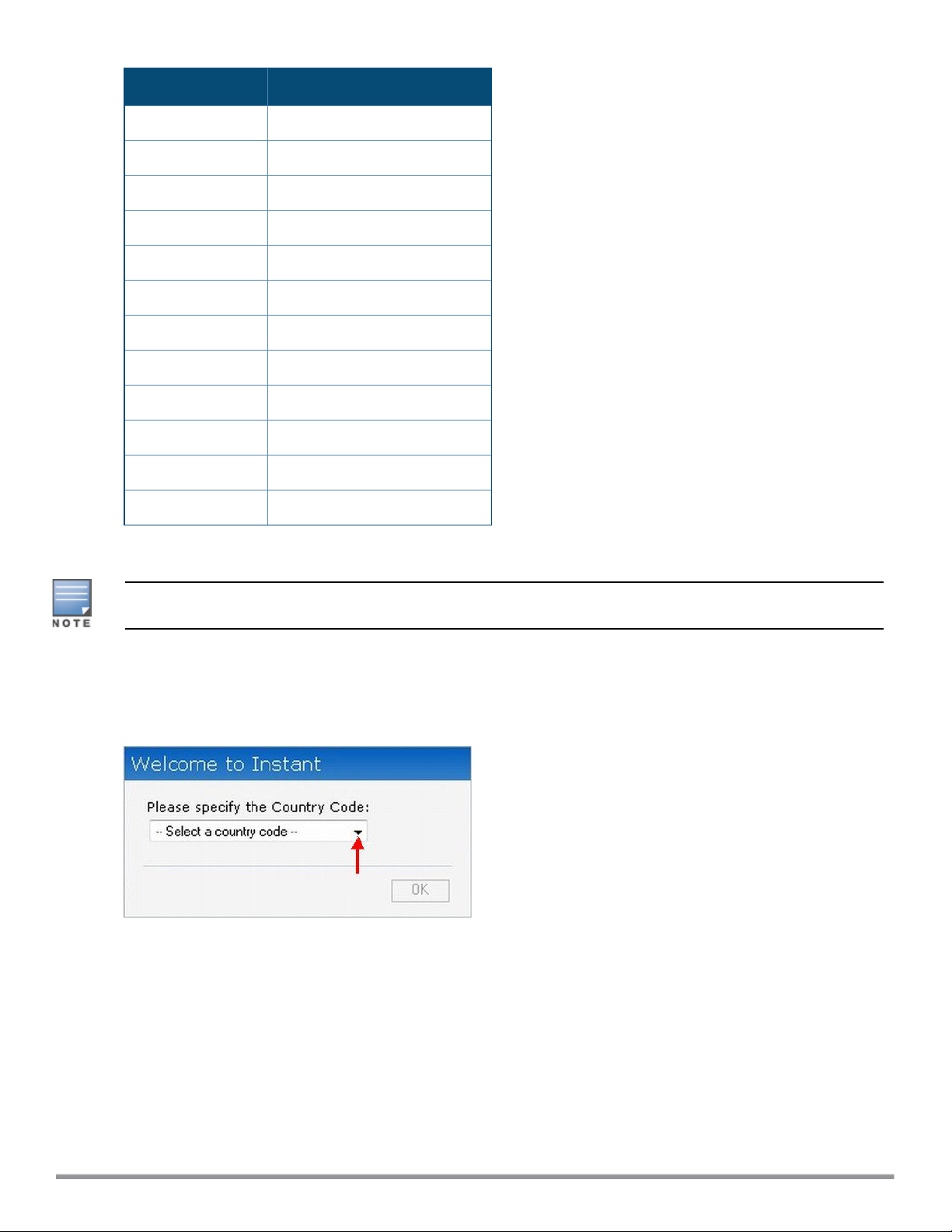
Launch a Web browser and enter instant.dell-pcw.com. In the login screen, enter the following credentials:
l Username— admin
l Password— admin
The following figure shows the Login screen:
Figure 1 Login Screen
Dell NetworkingW-Series Instant 6.4.0.2-4.1 | User Guide Setting up a W-IAP | 37
Page 38

When you use a provisioning Wi-Fi network to connect to the Internet, all browser requests are directed to the Instant
UI. For example, if you enter example.com in the address field, you are directed to the Instant UI. You can change
the default login credentials after the first login.
Regulatory Domains
The IEEE 802.11/b/g/n Wi-Fi networks operate in the 2.4 GHz spectrum and IEEE 802.11a/n operates in the 5.0
GHz spectrum. The spectrum is divided into channels. The 2.4 GHz spectrum is divided into 14 overlapping,
staggered 20 MHz wireless carrier channels. These channels are spaced 5 MHz apart. The 5 GHz spectrum is
divided into more channels. The channels that can be used in a particular country differ based on the regulations of
that country.
The initial Wi-Fi setup requires you to specify the country code for the country in which the Instant operates. This
configuration sets the regulatory domain for the radio frequencies that the W-IAPs use. Within the regulated
transmission spectrum, a high-throughput 802.11ac, 802.11a, 802.11b/g, or 802.11n radio setting can be configured.
The available 20 MHz, 40 MHz, or 80MHz channels are dependent on the specified country code.
You cannot change the country code for the W-IAPs in the restricted regulatory domains such as US or Japan for
most of the W-IAP models. Improper country code assignments can disrupt wireless transmissions. Most countries
impose penalties and sanctions on operators of wireless networks with devices set to improper country codes.
Country Code
The following table provides a list of supported country codes:
Table 7:
Country Codes List
Code Country Name
AE United Arab Emirates
AR Argentina
AT Austria
AU Australia
BG Bulgaria
BH Bahrain
BM Bermuda
BO Bolivia
BR Brazil
CA Canada
CH Switzerland
CL Chile
CN China
CO Colombia
CR Costa Rica
38 | Setting up a W-IAP Dell Networking W-Series Instant 6.4.0.2-4.1 | User Guide
Page 39

Code Country Name
CS Serbia and Montenegro
CY Cyprus
CZ Czech Republic
DE Germany
DK Denmark
DO Dominican Republic
DZ Algeria
EC Ecuador
EE Estonia
EG Egypt
ES Spain
FI Finland
FR France
GB United Kingdom
GR Greece
GT Guatemala
HK Hong Kong
HN Honduras
ID Indonesia
IE Ireland
IN India
IS Iceland
IT Italy
JM Jamaica
JO Jordan
JP Japan
KE Kenya
KR Republic of Korea (South
Korea)
Dell NetworkingW-Series Instant 6.4.0.2-4.1 | User Guide Setting up a W-IAP | 39
Page 40

Code Country Name
KW Kuwait
LB Lebanon
LI Liechtenstein
LI Liechtenstein
LK Sri Lanka
LT Lithuania
LU Luxembourg
MA Morocco
MU Mauritius
MX Mexico
NL Netherlands
NO Norway
NZ New Zealand
OM Oman
PA Panama
PE Peru
PH Philippines
PK Islamic Republic of Pakistan
PL Poland
PR Puerto Rico
PT Portugal
QA Qatar
RO Romania
RU Russia
SA Saudi Arabia
SG Singapore
SI Slovenia
SK Slovak Republic
40 | Setting up a W-IAP Dell Networking W-Series Instant 6.4.0.2-4.1 | User Guide
Page 41
Code Country Name
SV El Salvador
TH Thailand
TN Tunisia
TR Turkey
TT Trinidad and Tobago
TW Taiwan
UA Ukraine
US United States
UY Uruguay
VE Venezuela
VN Vietnam
ZA South Africa
Specifying Country Code
This procedure is applicable to the W-IAP-RW (Rest of World) variants only. Skip this step if you are installing WIAP in the United States and Japan.
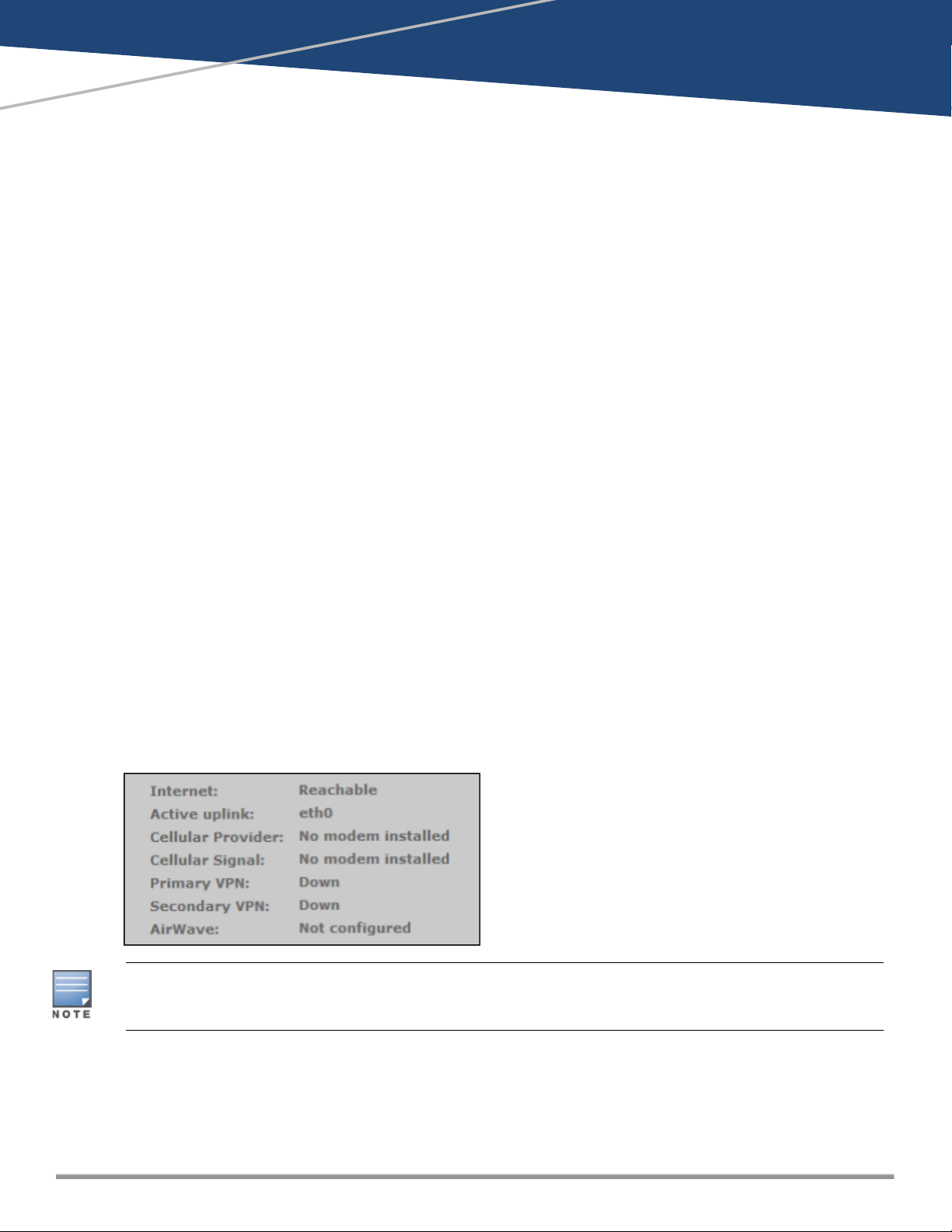
The Country Code window is displayed for the W-IAP-RW (Rest of World) variants when you log in to the UI for the
first time. You can specify a country code by selecting an appropriate option from the Please Specify the Country
Code drop-down list.
Figure 2 Specifying a Country Code
.
For the complete list of the country codes supported by the W-IAP-RW variant type, see Country Code on page 38.
Accessing the Instant CLI
Instant supports the use of Command Line Interface (CLI) for scripting purposes. When you make configuration
changes on a master W-IAP in the CLI, all associated W-IAPs in the cluster inherit these changes and subsequently
update their configurations. By default, you can access the CLI from the serial port or from an SSH session. You
must explicitly enable Telnet access on the W-IAP to access the CLI through a Telnet session.
For information on enabling SSH and Telnet access to the W-IAP CLI, see Configuring Terminal Access on page 80.
Dell NetworkingW-Series Instant 6.4.0.2-4.1 | User Guide Setting up a W-IAP | 41
Page 42

Connecting to a CLI Session
On connecting to a CLI session, the system displays its host name followed by the login prompt. Use the
administrator credentials to start a CLI session. For example:
(Instant AP)
User: admin
If the login is successful, the privileged command mode is enabled and a command prompt is displayed. For
example:
(Instant AP)#
The privileged mode provides access to show, clear, ping, traceroute, and commit commands. The configuration
commands are available in config mode. To move from privileged mode to the configuration mode, enter the
following command at the command prompt:
(Instant AP)# configure terminal
The configure terminal command allows you to enterthe basic configuration mode and the command prompt is
displayed as follows:
(Instant AP)(config)#
The Instant CLI allows CLI scripting in several other sub-command modes to allow the users to configure individual
interfaces, SSIDs, access rules, and security settings.
You can use the question mark (?) to view the commands available in a privileged mode, configuration mode, or submode.
Although automatic completion is supported for some commands such as configure terminal, the complete exit
and end commands must be entered at command prompt.
Applying Configuration Changes
Each command processed by the Virtual Controller is applied on all the slaves in a cluster. The changes configured
in a CLI session are saved in the CLI context. The CLI does not support the configuration data exceeding the 4K
buffer size in a CLI session. Therefore, it is recommended that you configure fewer changes at a time and apply the
changes at regular intervals.
To apply and save the configuration changes at regular intervals, use the following command in the privileged mode:
(Instant AP)# commit apply
To apply the configuration changes to the cluster without saving the configuration, use the following command in the
privileged mode:
(Instant AP)# commit apply no-save
To view the changes that are yet to be applied, use the following command in the privileged mode:
(Instant AP)# show uncommitted-config
To revert to the earlier configuration, use the following command in the privileged mode.
(Instant AP)# commit revert
Example:
(Instant AP)(config)# rf dot11a-radio-profile
(Instant AP)(RF dot11a Radio Profile)# beacon-interval 200
(Instant AP)(RF dot11a Radio Profile)# no legacy-mode
(Instant AP)(RF dot11a Radio Profile)# dot11h
(Instant AP)(RF dot11a Radio Profile)# interference-immunity 3
(Instant AP)(RF dot11a Radio Profile)# csa-count 2
(Instant AP)(RF dot11a Radio Profile)# spectrum-monitor
(Instant AP)(RF dot11a Radio Profile)# end
42 | Setting up a W-IAP Dell Networking W-Series Instant 6.4.0.2-4.1 | User Guide
Page 43

(Instant AP)# show uncommitted-config
rf dot11a-radio-profile
no legacy-mode
beacon-interval 200
no dot11h
interference-immunity 3
csa-count 1
no spectrum-monitor
Instant Access Point# commit apply
Using Sequence Sensitive Commands
The Instant CLI does not support positioning or precedence of sequence-sensitive commands. Therefore, it is
recommended that you remove the existing configuration before adding or modifying the configuration details for
sequence-sensitive commands. You can either delete an existing profile or remove a specific configuration by using
the no… commands.
The following table lists the sequence-sensitive commands and the corresponding no command to remove the
configuration.
Table 8:
Sequence-Sensitive Commands
Sequence-Sensitive Command Corresponding no command
opendns <username <password> no opendns
rule <dest> <mask> <match> <protocol> <start-port>
<end-port> {permit |deny | src-nat | dst-nat {<IP-
address> <port>| <port>}}[<option1....option9>]
mgmt-auth-server <auth-profile-name>
set-role <attribute>{{equals| not-equals| startswith| ends-with| contains} <operator> <role>| valueof}
set-vlan <attribute>{{equals| not-equals| startswith| ends-with| contains} <operator> <VLAN-ID>|
value-of}
auth-server <name> no auth-server <name>
no rule <dest> <:mask> <match>
<protocol> <start-port> <end-port>
{permit | deny | src-nat | dst-nat}
no mgmt-auth-server <auth-profilename>
no set-role <attribute>{{equals|
not-equals| starts-with| ends-with|
contains} <operator>| value-of}
no set-role
no set-vlan <attribute>{{equals|
not-equals| starts-with| ends-with|
contains} <operator>| value-of}
no set-vlan
Dell NetworkingW-Series Instant 6.4.0.2-4.1 | User Guide Setting up a W-IAP | 43
Page 44
This chapter describes the following Instant UI elements:
l Login Screen
l Main Window
Login Screen
The Instant login page allows you to:
l Log in to the Instant UI.
l View Instant Network Connectivity summary
l View the Instant UI in a specific language
Logging into the Instant UI
Chapter 4
Instant User Interface
To log in to the Instant UI, enter the following credentials:
l Username— admin
l Password— admin
The Instant UI main window is displayed.
Viewing Connectivity Summary
The Login page also displays the connectivity status to the Instant network. The users can view a summary that
indicates the status of the Internet availability, uplink, cellular modem and signal strength, VPN, and W-AirWave
configuration details before logging in to the Instant UI.
The following figure shows the information displayed in the connectivity summary:
Figure 3 Connectivity Summary
The Internet status is available only if the Internet failover feature (System > Show advanced option > uplink >
Internet failover) is enabled.
The cellular provider and cellular strength information is only available when a 3G or 4G modem is in use.
Language
The Language drop-down lists the languages and allows users to select their preferred language before logging in to
the Instant UI. A default language is selected based on the language preferences in the client desktop operating
system or browser. If Instant cannot detect the language, then English is used as the default language.
Dell NetworkingW-Series Instant 6.4.0.2-4.1 | User Guide Instant User Interface | 44
Page 45
You can also select the required language option from the Languages drop-down located at the bottom left corner of
the Instant main window.
Main Window
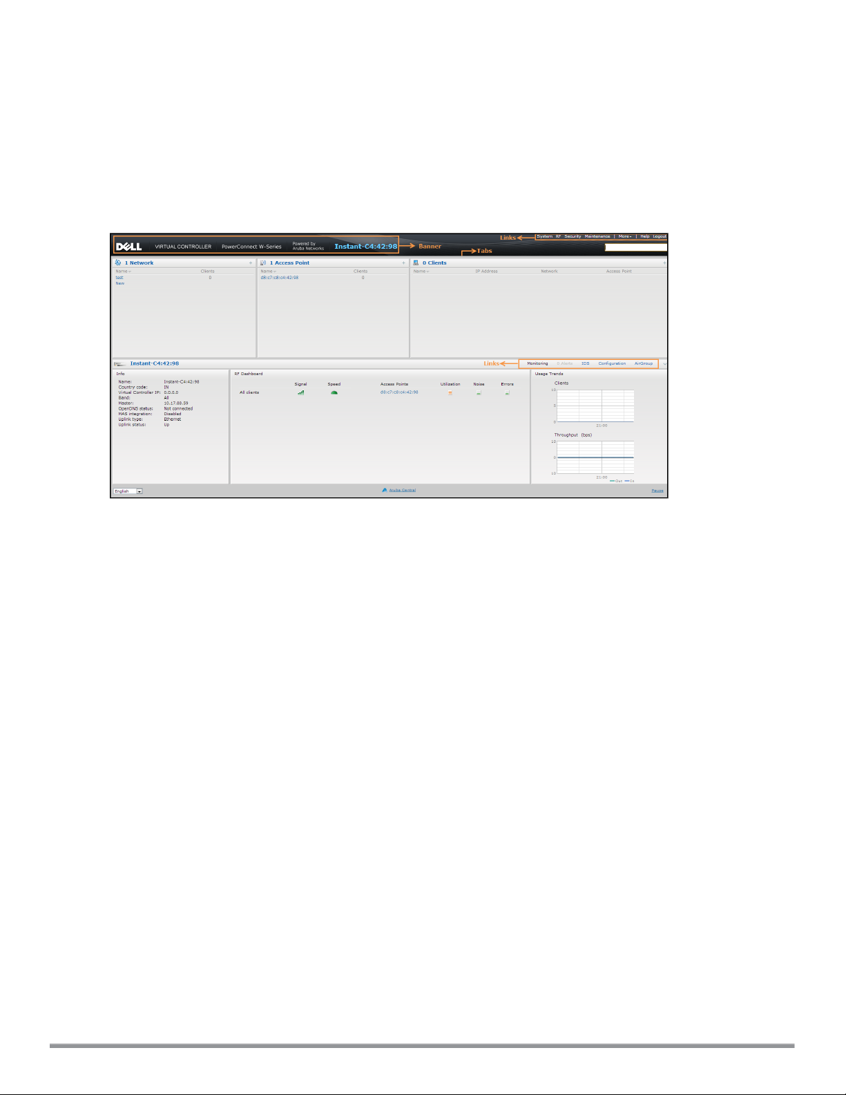
On logging into Instant, the Instant UI Main Window is displayed. The following figure shows the Instant main
window:
Figure 4 Instant Main Window
The main window consists of the following elements:
l Banner
l Search
l Tabs
l Links
l Views
Banner
The banner is a horizontal rectangle that appears at the top left corner of the Instant main window. It displays the
company name, logo, and Virtual Controller's name.
Search
Administrators can search for a W-IAP, client, or a network in the Search text box. When you type a search text, the
search function suggests matching keywords and allows you to automatically complete the search text entry.
Tabs
The Instant main window consists of the following tabs:
n Networks Tab— Provides information about the network profiles configured in the Instant network.
n Access Points Tab— Provides information about the W-IAPs configured in the Instant network.
n Clients Tab— Provides information about the clients in the Instant network.
Each tab appears in a compressed view by default. The number of networks, W-IAPs, or clients in the network
precedes the tab names. The individual tabs can be expanded or collapsed by clicking on the tabs. The list items in
each tab can be sorted by clicking the triangle icon next to the heading labels.
45 | Instant User Interface DellNetworking W-Series Instant 6.4.0.2-4.1 | User Guide
Page 46

Networks Tab
This tab displays a list of Wi-Fi networks that are configured in the Instant network. The network names are
displayed as links. The expanded view displays the following information about each WLAN SSID:
l Name (SSID) — Name of the network.
l Clients — Number of clients that are connected to the network.
l Type — Type of network type such as Employee, Guest, or Voice.
l Band — Band in which the network is broadcast: 2.4 GHz band, 5 GHz band, or both.
l Authentication Method — Authentication method required to connect to the network.
l Key Management — Authentication key type.
l IP Assignment— Source of IP address for the client.
l Zone—AP zone configured on the SSID.
To add a wireless network profile, click the New link in the Networks tab. To edit, click the edit link that is displayed
on clicking the network name in the Networks tab. To delete a network, click on the link x.
For more information on the procedure to add or modify a wireless network, see Wireless Network Profiles on page
93.
Access Points Tab
If the Auto Join Mode feature is enabled, a list of enabled and active W-IAPs in the Instant network is displayed in
the Access Points tab. The W-IAP names are displayed as links. If the Auto Join Mode feature is disabled, the New
link is displayed. Click this link to add a new W-IAP to the network. If a W-IAP is configured and not active, its MAC
Address is displayed in red.
The expanded view of the Access Points tab displays the following information about each W-IAP:
l Name — Name of the W-IAP. If the W-IAP functions as a master W-IAP in the network, the asterisk sign "*" is
displayed next to the W-IAP.
l IP Address — IP address of the W-IAP.
l Mode — Mode of the W-IAP.
n Access — In this mode, the AP serves clients and scans the home channel for spectrum analysis while
monitoring channels for rogue APs in the background.
n Monitor — In this mode, the AP acts as a dedicated Air Monitor (AM), scanning all channels for rogue APs and
clients.
l Spectrum— When enabled, the AP functions as a dedicated full-spectrum RF monitor, scanning all channels to
detect interference from neighboring APs or non-Wi-Fi devices such as microwaves and cordless phones. When
Spectrum is enabled, the AP does not provide access services to clients.
l Clients — Number of clients that are currently associated to the W-IAP.
l Type — Model number of the W-IAP.
l Zone—AP zone.
l Channel — Channel on which the W-IAP is currently broadcast.
l Power (dB) — Maximum transmission EIRP of the radio.
l Utilization (%) — Percentage of time that the channel is utilized.
l Noise (dBm) — Noise floor of the channel.
An edit link is displayed on clicking the W-IAP name. For details about editing W-IAP settings see Customizing W-
IAP Settings on page 84.
Dell NetworkingW-Series Instant 6.4.0.2-4.1 | User Guide Instant User Interface | 46
Page 47

Clients Tab
This tab displays a list of clients that are connected to the Instant network. The client names are displayed as links.
The expanded view displays the following information about each client:
l Name — User name of the client or guest users if available.
l IP Address — IP address of the client.
l MAC Address — MAC address of the client.
l OS — Operating system that runs on the client.
l Network — The network to which the client is connected.
l Access Point — W-IAP to which the client is connected.
l Channel — The client operating channel.
l Type — Type of the Wi-Fi client: A, G, AN, or GN.
l Role — Role assigned to the client.
l Signal — Current signal strength of the client, as detected by the AP.
l Speed (mbps) — Current speed at which data is transmitted. When the client is associated with an AP, it
constantly negotiates the speed of data transfer. A value of 0 means that the AP has not heard from the client for
some time.
Links
l The following links allow you to configure various features for the Instant network:
l New Version Available
l System
l RF
l Security
l Maintenance
l More
l Help
l Logout
l Monitoring
l Client Match
l AppRF
l Spectrum
l Alerts
l IDS
l Configuration
l AirGroup
l W-AirWave Setup
l Pause/Resume
Each of these links is explained in the subsequent sections.
New Version Available
This link is displayed in the top right corner of the Instant main window only if a new image version is available on the
image server and W-AirWave is not configured. For more information about the New version available link and its
functions, see Upgrading a W-IAP on page 317.
47 | Instant User Interface DellNetworking W-Series Instant 6.4.0.2-4.1 | User Guide
Page 48

System
This link displays the System window. The System window consists of the following tabs:
Use the Show/Hide Advanced option at the bottom of the System window to view or hide the advanced options.
l General— Allows you to configure, view or edit the Name, IP address, NTP Server, and other W-IAP settings for
the Virtual Controller. For more information on the basic and additional configuration settings that can be
performed on this tab, see Basic Configuration Tasks on page 74 and Additional Configuration Tasks on page 78.
l Admin — Allows you to configure administrator credentials for access to the Virtual Controller Management User
Interface. You can also configure W-AirWave in this tab. For more information on management interface and WAirWave configuration, see Managing W-IAP Users on page 140 and Managing a W-IAP from W-AirWave on
page 275 respectively.
l Uplink — Allows you to view or configure uplink settings. See Uplink Configuration on page 285 for more
information.
l L3 Mobility — Allows you to view or configure the Layer-3 mobility settings. See Configuring L3-Mobility on page
307 for more information.
l Enterprise Domains — Allows you to view or configure the DNS domain names that are valid in the enterprise
network. See Configuring Enterprise Domains on page 188 for more information.
l Monitoring — Allows you to view or configure the following details:
n Syslog — Allows you to view or configure Syslog Server details for sending syslog messages to the external
servers. See Configuring a Syslog Server on page 330 for more information.
n TFTP Dump — Allows you to view or configure a TFTP dump server for core dump files. See Configuring
TFTP Dump Server on page 332 for more information.
n SNMP — Allows you to view or configure SNMP agent settings. See Configuring SNMP on page 327 for more
information.
l WISPr — Allows you to view or configure the WISPr settings. See Configuring WISPr Authentication on page 170
for more information.
l Proxy — Allows you to configure HTTP proxy on a W-IAP. See Configuring HTTP Proxy on a W-IAP on page 317
for more information.
The following figure provides a view of the System window with the advanced options.
Dell NetworkingW-Series Instant 6.4.0.2-4.1 | User Guide Instant User Interface | 48
Page 49
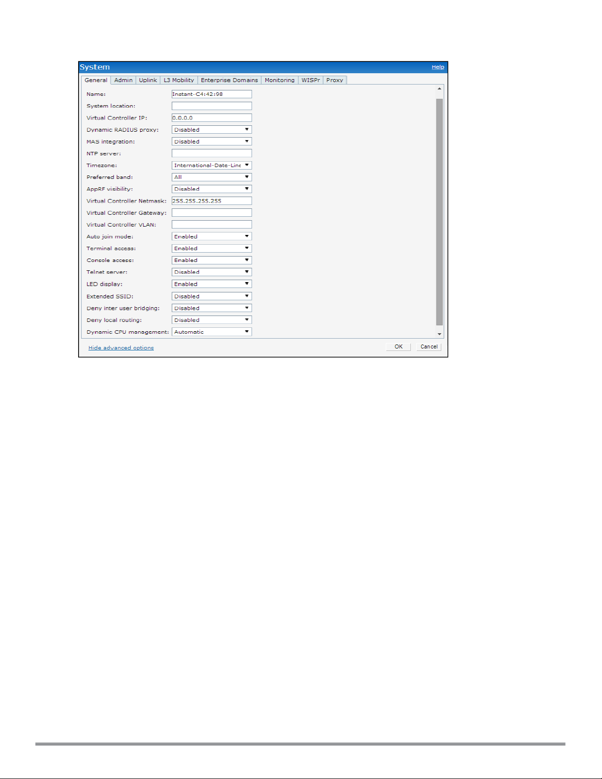
Figure 5 System Window
RF
The RFlink displays a window for configuring Adaptive Radio Management (ARM) and Radio features.
l ARM — Allows you to view or configure channel and power settings for all the W-IAPs in the network. For
information about ARM configuration, see ARM Overview on page 232.
l Radio — Allows you to view or configure radio settings for 2.4 GHz and the 5 GHz radio profiles. For information
about Radio, see Configuring Radio Settings for a W-IAP on page 238.
The following figure provides a view of the RF window with the advanced options for ARM configuration:
49 | Instant User Interface DellNetworking W-Series Instant 6.4.0.2-4.1 | User Guide
Page 50
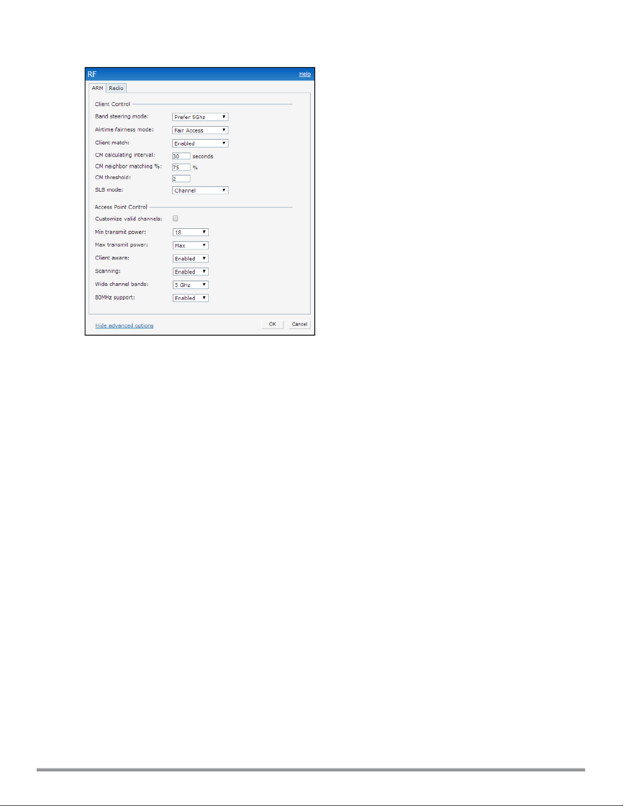
Figure 6 RF Window
Security
The Security link displays a window with the following tabs:
l Authentication Servers— Use this tab to configure an external RADIUS server for a wireless network. For more
information, see Configuring an External Server for Authentication on page 157.
l Users for Internal Server— Use this tab to populate the system’s internal authentication server with users. This
list is used by networks for which per-user authorization is specified using the Virtual Controller’s internal
authentication server. For more information about users, see Managing W-IAP Users on page 140.
l Roles— Use this tab to view the roles defined for all the Networks. The Access Rules part allows you to configure
permissions for each role. For more information, see Configuring User Roles on page 190 and Configuring
AccessRules for Network Services on page 177.
l Blacklisting— Use this tab to blacklist clients. For more information, see Blacklisting Clients on page 171.
l Firewall Settings— Use this tab to enable or disable Application Layer Gateway (ALG) supporting address and
port translation for various protocols and to configure protection against wired attacks. For more information, see
Configuring ALG Protocols on page 181 and Configuring Firewall Settings for Protection from ARP Attacks on
page 181
l Inbound Firewall— Use this tab to enhance the inbound firewall by allowing configuration of inbound firewall
rules, management subnets, and restricted corporate access through an uplink switch. For more information, see
Managing Inbound Traffic on page 183.
l Walled Garden—Use this window to allow or prevent access to a selected list of websites. For more information,
see Configuring Walled Garden Access on page 138.
l External Captive Portal— Use this window to configure external captive portal profiles. For more information,
see Configuring External Captive Portal for a Guest Network on page 129.
The following figure shows the default view of the Security window:
Dell NetworkingW-Series Instant 6.4.0.2-4.1 | User Guide Instant User Interface | 50
Page 51
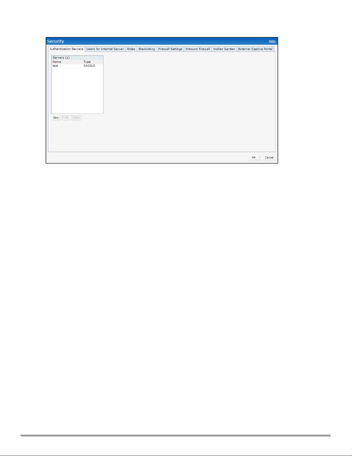
Figure 7 Security Window - Default View
Maintenance
The Maintenance link displays a window that allows you to maintain the Wi-Fi network. The Maintenance window
consists of the following tabs:
l About—Displays the name of the product, build time, W-IAP model name, the Instant version, website address of
Dell, and Copyright information.
l Configuration— Displays the following details:
n Current Configuration — Displays the current configuration details.
n Clear Configuration —Allows you to clear the current configuration details of the network.
n Backup Configuration — Allows you to back up local configuration details. The backed up configuration data
is saved in the file named instant.cfg.
n Restore Configuration — Allows you to restore the backed up configuration. The W-IAP must be rebooted
after restoring the configuration for the changes to affect.
l Certificates — Displays information about the certificates installed on the W-IAP. You can also upload new
certificates and set a passphrase for the certificates. For more information, see Uploading Certificates on page
173.
l Firmware — Displays the current firmware version and provides various options to upgrade to a new firmware
version. For more information, see Upgrading a W-IAP on page 317.
l Reboot — Displays the W-IAPs in the network and provides an option to reboot the required access point or all
access points. For more information, see Upgrading a W-IAP on page 317.
l Convert — Provides an option to convert a W-IAP to a mobility controller managed Remote AP or Campus AP, or
to the default Virtual Controller mode. For more information, see Converting a W-IAP to a Remote AP and
Campus AP on page 320.
The following figure shows the default view of the Maintenance window:
51 | Instant User Interface DellNetworking W-Series Instant 6.4.0.2-4.1 | User Guide
Page 52
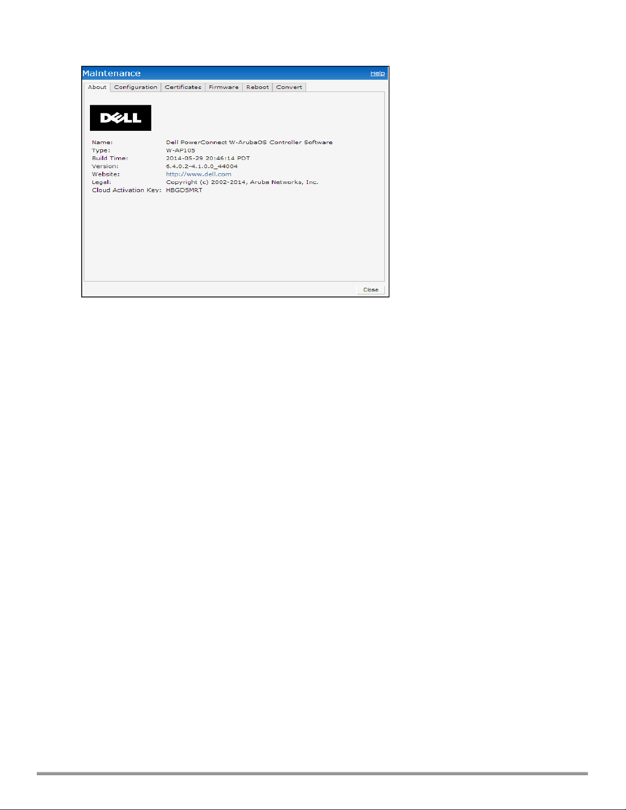
Figure 8 Maintenance Window - Default View
More
The More link allows you to select the following options:
l VPN
l IDS
l Wired
l Services
l DHCP Server
l Support
VPN
The VPNwindow allows you to define communication settings with a remote Controller. See VPN Configuration on
page 210 for more information. The following figure shows an example of the IPSec configuration options available in
the VPN window:
Dell NetworkingW-Series Instant 6.4.0.2-4.1 | User Guide Instant User Interface | 52
Page 53
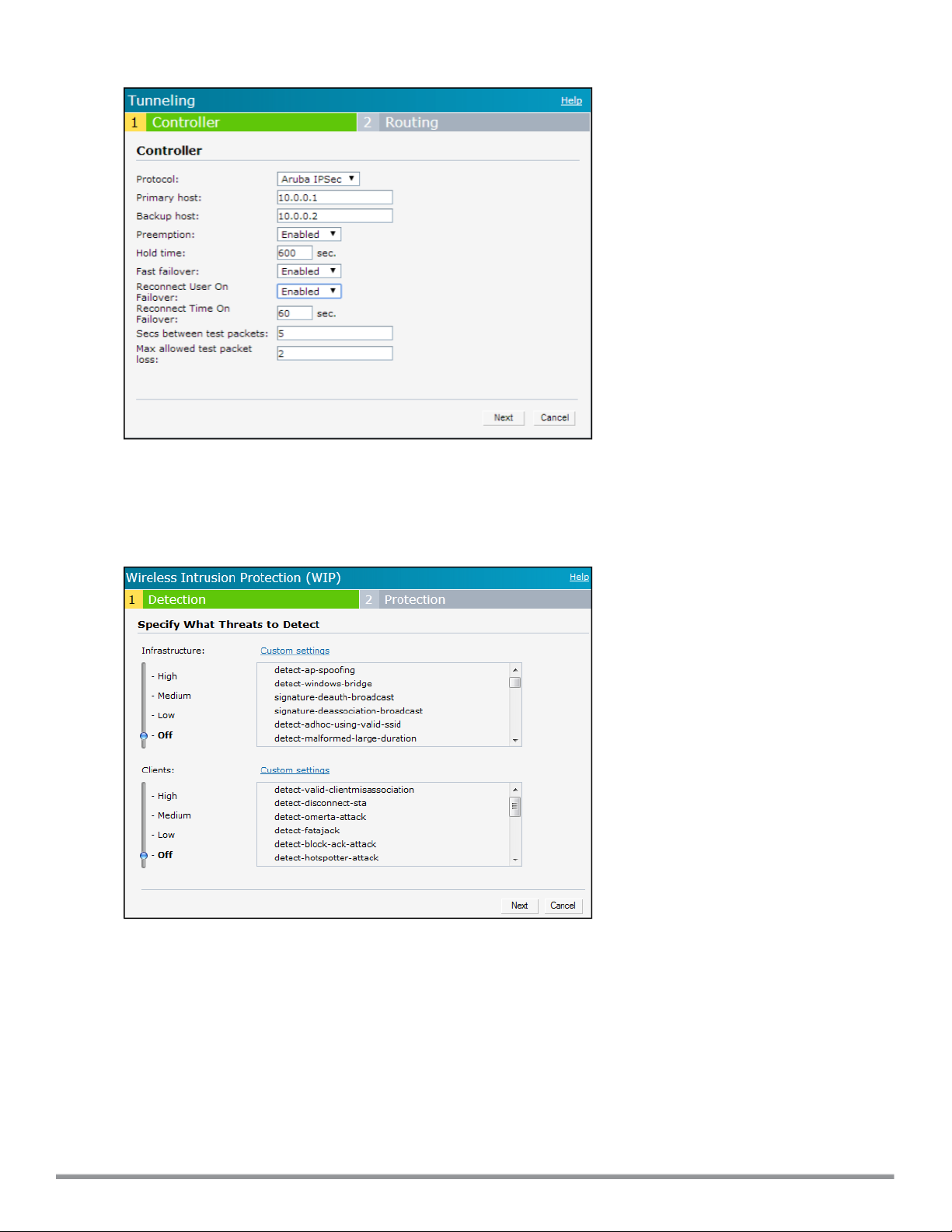
Figure 9 VPN window for IPSec Configuration
IDS
The IDSwindow allows you to configure wireless intrusion detection and protection levels. The following figures
show the IDS window:
Figure 10 IDS Window: Intrusion Detection
53 | Instant User Interface DellNetworking W-Series Instant 6.4.0.2-4.1 | User Guide
Page 54
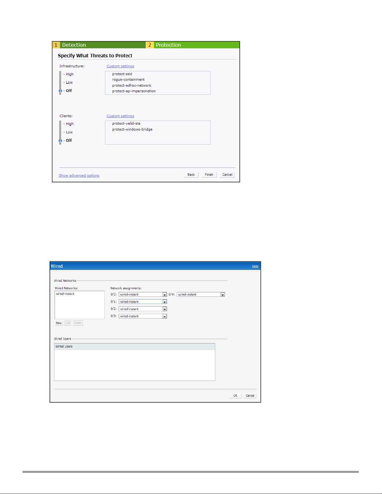
Figure 11 IDS Window: Intrusion Protection
For more information on wireless intrusion detection and protection, see Detecting and Classifying Rogue APs on
page 296.
Wired
The Wired window allows you to configure a wired network profile. See Wired Profiles on page 112 for more
information. The following figure shows the Wired window:
Figure 12 Wired Window
Services
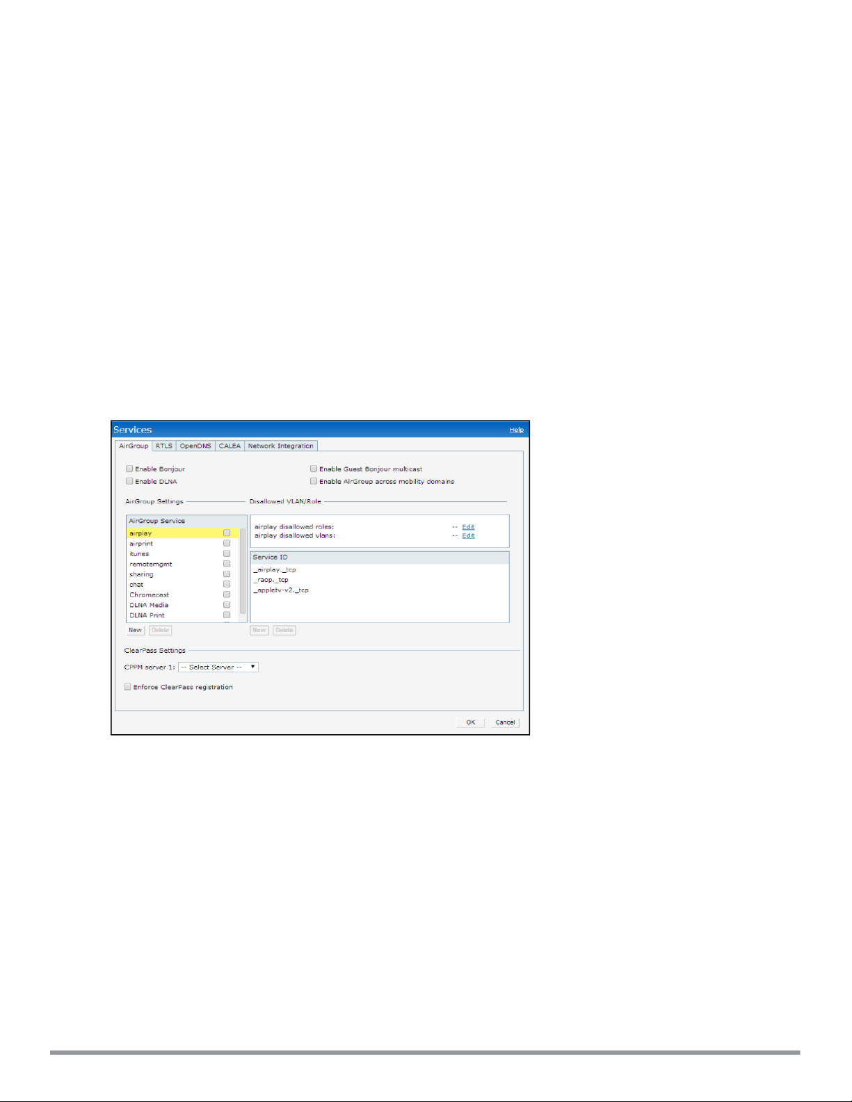
The Services window allows you to configure services such as AirGroup, RTLS, and OpenDNS. The Services
window consists of the following tabs:
l AirGroup — Allows you to configure the AirGroup and AirGroup services. For more information, see AirGroup
Configuration on page 255.
Dell NetworkingW-Series Instant 6.4.0.2-4.1 | User Guide Instant User Interface | 54
Page 55
l RTLS — Allows you to integrate W-AirWave Management platform or third-party Real Time Location Server such
as Aeroscout Real Time Location Server with Instant. For more information, see Configuring a W-IAP for
RTLSSupport on page 263.
The RTLS tab also allows you to integrate W-IAP with the Analytics and Location Engine (ALE). For more
information about configuring a W-IAP for ALE integration, see Configuring a W-IAP for Analytics and Location
Engine Support on page 265.
l OpenDNS— Allows you to configure support for OpenDNS business solutions, which require an OpenDNS
(opendns.com) account. The OpenDNS credentials are used by Instant and W-AirWave to filter content at the
enterprise level. For more information, see Configuring OpenDNS Credentials on page 266.
l CALEA—Allows you configure support for Communications Assistance for Law Enforcement Act (CALEA)
server integration, thereby ensuring compliance with Lawful Intercept and CALEA specifications. For more
information, see CALEA Integration and Lawful Intercept Compliance on page 270.
l Network Integration—Allows you to configure a W-IAP for integration with Palo Alto Networks (PAN) Firewall
and XML API server. For more information about W-IAP integration with PAN, see Integrating a W-IAP with Palo
Alto Networks Firewall on page 267and Integrating a W-IAP with an XMLAPIinterface on page 268.
The following figure shows the default view of the Services window:
Figure 13 Services Window: Default View
DHCP Server
The DHCP Servers window allows you to configure various DHCP modes. The following figure shows the contents
of the DHCP Servers window:
55 | Instant User Interface DellNetworking W-Series Instant 6.4.0.2-4.1 | User Guide
Page 56
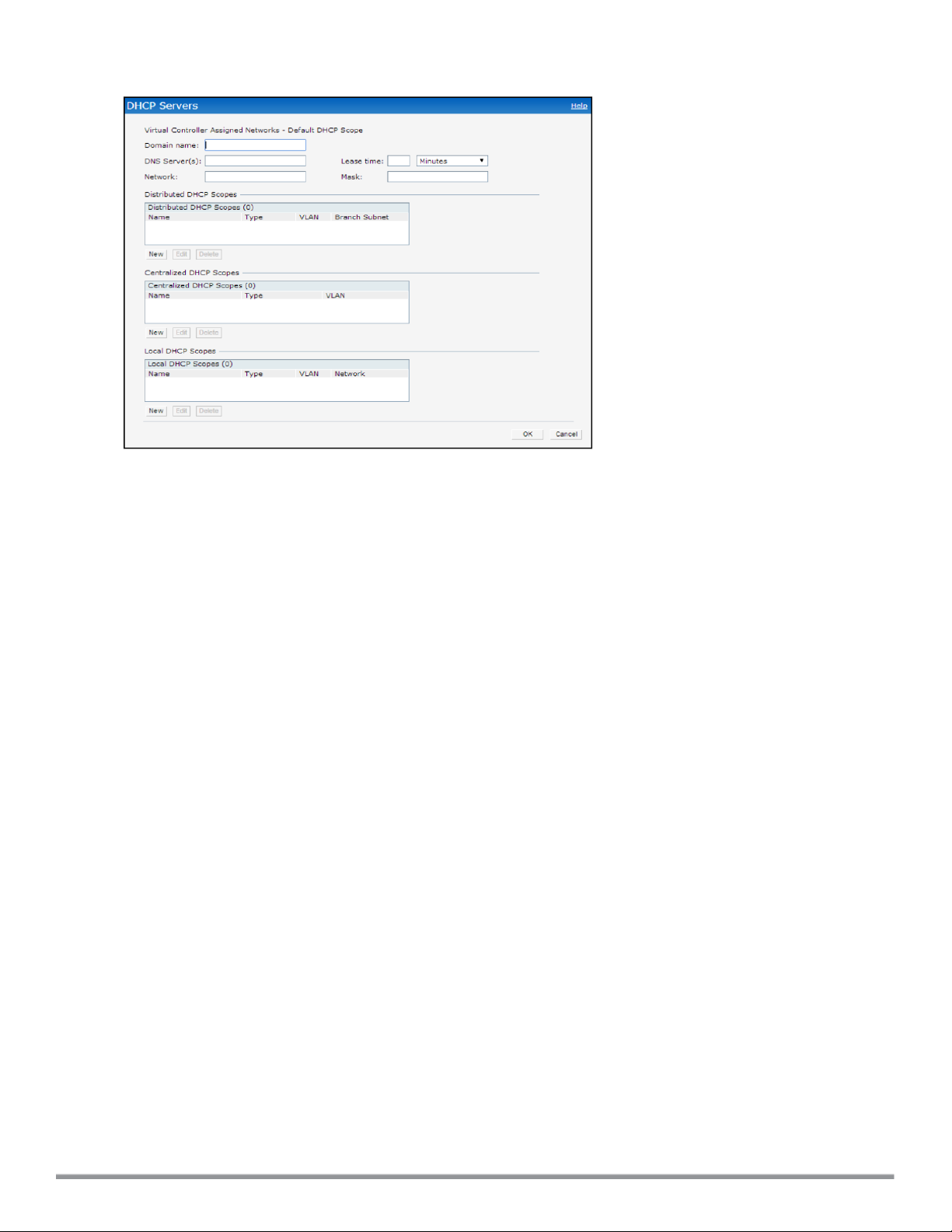
Figure 14 DHCP Servers Window
For more information, see DHCP Configuration on page 201.
Support
The Support consists of the following fields:
l Command— Allows you to select a support command for execution.
l Target—Displays a list of W-IAPs in the network.
l Run— Allows you to execute the selected command for a specific W-IAP or all W-IAPs and view logs.
l Auto Run— Allows you to configure a schedule for automatic execution of a support command for a specific W-
IAP or all W-IAPs.
l Filter—Allows you to filter the contents of a command output.
l Clear—Clears the command output displayed after a command is executed.
l Save— Allows you to save the support command logs as an HTML or text file.
For more information on support commands, see Running Debug Commands from the UI on page 333. The following
figure shows the Support window:
Dell NetworkingW-Series Instant 6.4.0.2-4.1 | User Guide Instant User Interface | 56
Page 57

Figure 15 Support Window
Help
The Help link allows you to view a short description or definition of selected terms and fields in the UI windows or
dialogs.
To activate the context-sensitive help:
1. Click the Help link at the top right corner of Instant main window.
2. Click any text or term displayed in green italics to view its description or definition.
3. To disable the help mode, click Done.
Logout
The Logout link allows you to log out of the Instant UI.
Monitoring
The Monitoring link displays the Monitoring pane for the Instant network. Use the down arrow located to the
right side of these links to compress or expand the monitoring pane.
The monitoring pane consists of the following sections:
l Info
l RF Dashboard
l RF Trends
l Usage Trends
l Mobility Trail
Info
The Info section displays the configuration information of the Virtual Controller by default. On selecting the Network
View tab, the monitoring pane displays configuration information of the selected network. Similarly in the Access
Point or the Client view, this section displays the configuration information of the selected W-IAP or the client.
57 | Instant User Interface DellNetworking W-Series Instant 6.4.0.2-4.1 | User Guide
Page 58

Table 9:
Contents of the Info Section in the Instant Main Window
Name Description
Info section in Virtual
Controller view
Info section in Network view
The Info section in the Virtual Controller view displays the following information:
l Name— Displays the Virtual Controller name.
l Country Code— Displays the Country in which the Virtual Controller is operating.
l Virtual Controller IP address— Displays the IP address of the Virtual Controller.
l Management: Indicates if the W-IAP is managed locally or through W-AirWave.
l Master— Displays the IP address of the Access Point acting as Virtual Controller.
l OpenDNS Status— Displays the OpenDNS status. If the OpenDNS status
indicates Not Connected, ensure that the network connection is up and
appropriate credentials are configured for OpenDNS.
l Uplink type — Displays the type of uplink configured on the W-IAP, for example,
Ethernet or 3G.
l Uplink stat us — Indicates the uplink status.
l Blacklisted clients — Displays the number of blacklisted clients.
l Internal RADIUS Users — Displays the number of internal RADIUSusers.
l Internal Guest Users — Displays the number of internal guest users.
l Internal User Open Slots— Displays the available slots for user configuration as
supported by the W-IAP model.
The Info section in the Network view displays the following information:
l Name — Displays the name of the network.
l Status — Displays the status of the network.
l Type — Displays the type of network, for example, Employee, Guest, or Voice.
l IP Assignment— Indicates if the W-IAP clients are assigned IP address from the
network that the Virtual Controller is connected to, or from an internal autogenerated IP scope from the Virtual Controller.
l Access— Indicates the level of access control configured for the network.
l WMM DSCP—Displays WMMDSCP mapping details.
l Security level— Indicates the type of user authentication and data encryption
configured for the network.
Info section in Access Point
view
Info section in Client view
The info section for WLAN SSIDs also indicates status of Captive Portal and CALEA
ACLs and provides a link to upload certificates for internal server. For more
information, see Uploading Certificates on page 173.
The Info section in the Access Point view displays the following information:
l Name — Displays the name of the selected W-IAP.
l IP Address — Displays the IP address of the W-IAP.
l Mode — Displays the mode in which the AP is configured to operate:
l In Access mode, the W-IAP serves clients, while also monitoring
for rogue APs in the background.
l In Monitor mode, the W-IAP acts as a dedicated monitor, scanning
all channels for rogue APs and clients.
l Spectrum — Displays the status of the spectrum monitor.
l Clients — Number of clients associated with the W-IAP.
l Type — Displays the model number of the W-IAP.
l Zone — Displays AP zone details.
l CPU Utilization — Displays the CPU utilization in percentage.
l Memory Free — Displays the memory availability of the W-IAP in MB.
l Serial number — Displays the serial number of the W-IAP.
l MAC— Displays the MAC address.
l From Port— Displays the port from where the slave W-IAP is learned in hierarchy
mode.
The Info section in the Client view displays the following information:
l Name— Displays the name of the client.
Dell NetworkingW-Series Instant 6.4.0.2-4.1 | User Guide Instant User Interface | 58
Page 59
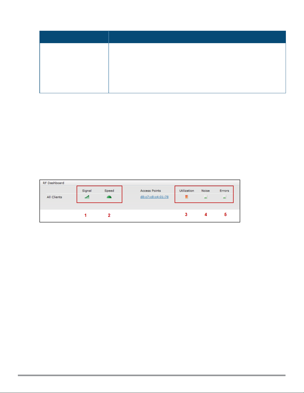
Table 9:
Contents of the Info Section in the Instant Main Window
Name Description
l IP Address— Displays IP address of the client.
l MAC Address— Displays MAC Address of the client.
l OS— Displays the Operating System that is running on the client.
l Network— Indicates the network to which the client is connected.
l Access Point— Indicates the W-IAP to which the client is connected.
l Channel— Indicates the channel that is currently used by the client.
l Type— Displays the channel type on which client is broadcasting.
l Role—Displays the role assigned to the client.
RF Dashboard
The RF Dashboard section lists the W-IAPs that exceed the utilization, noise, or error threshold. It also shows the
clients with low speed or signal strength in the network and the RF information for the W-IAP to which the client is
connected.
The W-IAP names are displayed as links. When a W-IAP is clicked, the W-IAP configuration information is
displayed in the Info section and the RF Dashboard section is displayed at the bottom left corner of the Instant main
window.
The following figure shows an example of the RF dashboard with Utilization, Band frames, Noise Floor, and Errors
details:
Figure 16 RF Dashboard in the Monitoring Pane
The following table describes the icons available on the RF Dashboard pane:
59 | Instant User Interface DellNetworking W-Series Instant 6.4.0.2-4.1 | User Guide
Page 60

Table 10:
RF Dashboard Icons
Icon Name Description
1 Signal
Icon
2 Speed
icon
3 Utilization
icon
Displays the signal strength of the client. Depending on the signal strength of the client, the color
of the lines on the Signal bar changes from Green > Orange > Red.
l Green— Signal strength is more than 20 decibels.
l Orange— Signal strength is between 15-20 decibels.
l Red— Signal strength is less than 15 decibels.
To view the signal graph for a client, click on the signal icon next to the client in the Signal
column.
Displays the data transfer speed of the client. Depending on the data transfer speed of the client,
the color of the Signal bar changes from Green > Orange > Red.
l Green— Data transfer speed is more than 50 percent of the maximum speed supported by
the client.
l Orange— Data transfer speed is between 25-50 percent of the maximum speed supported by
the client.
l Red— Data transfer speed is less than 25 percent of the maximum speed supported by the
client.
To view the data transfer speed graph of a client, click on the speed icon against the client in the
Speed column.
Displays the radio utilization rate of the W-IAPs. Depending on the percentage of utilization, the
color of the lines on the Utilization icon changes from Green > Orange > Red.
l Green— Utilization is less than 50 percent.
l Orange— Utilization is between 50-75 percent.
l Red— Utilization is more than 75 percent.
To view the utilization graph of a W-IAP, click the Utilization icon next to the W-IAP in the
Utilization column.
4 Noise icon Displays the noise floor details for the W-IAPs. Noise is measured in decibels/meter. Depending
on the noise floor, the color of the lines on the Noise icon changes from Green > Orange > Red.
l Green— Noise floor is more than 87 dBm.
l Orange— Noise floor is between 80 dBm-87 dBm.
l Red— Noise floor is less than 80 dBm.
To view the noise floor graph of a W-IAP, click the noise icon next to the W-IAP in the Noise
column.
5 Errors
icon
Displays the errors for the W-IAPs. Depending on the errors, color of the lines on the Errors icon
changes from Green > Yellow > Red.
l Green— Errors are less than 5000 frames per second.
l Orange— Errors are between 5000-10000 frames per second.
l Red— Errors are more than 10000 frames per second.
To view the errors graph of a W-IAP, click the Errors icon next to the W-IAP in the Errors column.
RF Trends
The RF Trends section displays the following graphs for the selected AP and the client. To view the details on the
graphs, click the graphs and hover the mouse on a data point:
Figure 17 RF Trends for Access Point
Dell NetworkingW-Series Instant 6.4.0.2-4.1 | User Guide Instant User Interface | 60
Page 61
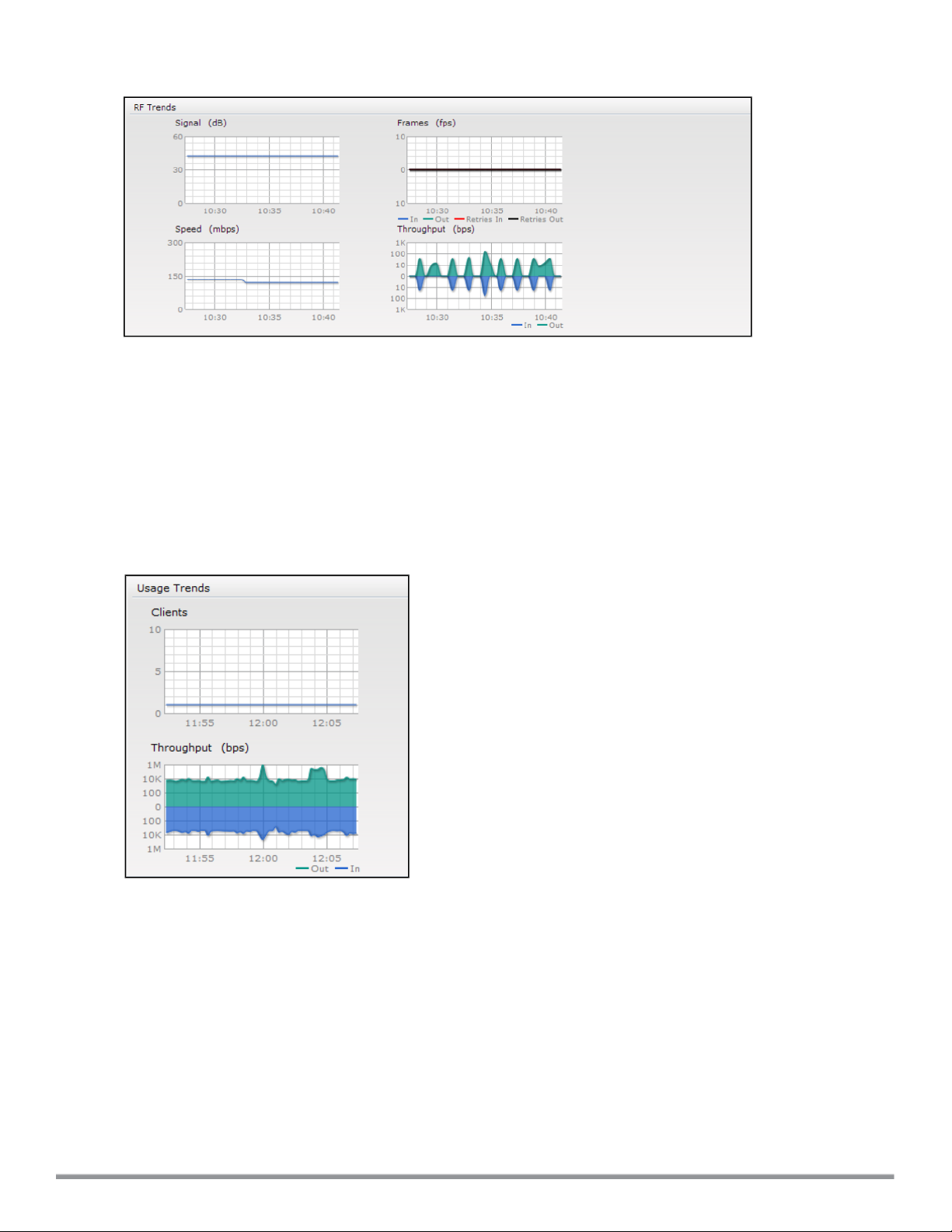
Figure 18 RF Trends for Clients
Usage Trends
The Usage Trends displays the following graphs:
l Clients — In the default view, the Clients graph displays the number of clients that were associated with the
Virtual Controller in the last 15 minutes. In Network or Access Points view, this graph displays the number of
clients that were associated with the selected network or W-IAP in the last 15 minutes.
l Throughput— In the default view, the Throughput graph displays the incoming and outgoing throughput traffic for
the Virtual Controller in the last 15 minutes. In the Network or Access Points view, this graph displays the
incoming and outgoing throughput traffic for the selected network or W-IAP in the last 15 minutes.
Figure 19 Usage Trends Graphs in the Default View
61 | Instant User Interface DellNetworking W-Series Instant 6.4.0.2-4.1 | User Guide
Page 62

The following table describes the graphs displayed in the Network view:
Table 11:
Network View — Graphs and Monitoring Procedures
Graph Name Description Monitoring Procedure
Clients The Clients graph shows the number of clients
associated with the network for the last 15
minutes.
To see an enlarged view, click the graph.
l The enlarged view provides Last, Minimum,
Maximum, and Average statistics for the
number of clients associated with the Virtual
Controller for the last 15 minutes.
l To see the exact number of clients in the
Instant network at a particular time, move the
cursor over the graph line.
Throughput The Throughput graph shows the throughput of
the selected network for the last 15 minutes.
l Outgoing traffic — Throughput for outgoing
traffic is displayed in green. Outgoing traffic is
shown above the median line.
l Incoming traffic — Throughput for incoming
traffic is displayed in blue. Incoming traffic is
shown below the median line.
To see an enlarged view, click the graph.
l The enlarged view provides Last, Minimum,
Maximum, and Average statistics for the
incoming and outgoing traffic throughput of the
network for the last 15 minutes.
To see the exact throughput of the selected
network at a particular time, move the cursor over
the graph line.
To check the number of clients associated
with the network for the last 15 minutes,
1. Log in to the Instant UI. The Virtual
Controller view appears. This is the
default view.
2. In the Networks tab, click the network for
which you want to check the client
association. The Network view is
displayed.
3. Study the Clients graph in the Usage
Trends pane. For example, the graph
shows that one client is associated with
the selected network at 12:00 hours.
To check the throughput of the selected
network for the last 15 minutes,
1. Log in to the Instant UI. The Virtual
Controller view is displayed. This is the
default view.
2. In the Networks tab, click the network for
which you want to check the client
association. The Network view is
displayed.
3. Study the Throughput graph in the Usage
Trends pane. For example, the graph
shows 22.0 Kbps incoming traffic
throughput for the selected network at
12:03 hours.
Dell NetworkingW-Series Instant 6.4.0.2-4.1 | User Guide Instant User Interface | 62
Page 63

The following table describes the graphs displayed in the Access Point view:
Table 12:
Graph
Name
Neighboring
APs
CPU
Utilization
Access Point View — Usage Trends and Monitoring Procedures
Description Monitoring Procedure
The Neighboring APs graph shows the
number of APs heard by the selected WIAP:
l Valid APs: An AP that is part of the
enterprise providing WLAN service.
l Interfering APs: An AP that is seen in
the RF environment but is not
connected to the network.
l Rogue APs: An unauthorized AP that is
plugged into the wired side of the
network.
To see the number of different types of
neighboring APs for the last 15 minutes,
move the cursor over the respective graph
lines.
The CPU Utilization graph displays the
utilization of CPU for the selected W-IAP.
To see the CPU utilization of the W-IAP,
move the cursor over the graph line.
To check the neighboring APs detected by the W-IAP
for the last 15 minutes,
1. Log in to the Instant UI. The Virtual Controller view
is displayed. This is the default view.
2. In the Access Points tab, click the W-IAP for which
you want to monitor the client association. The WIAP view is displayed.
3. Study the Neighboring APs graph in the Overview
section. For example, the graph shows that 148
interfering APs are detected by the W-IAP at 12:04
hours.
To check the CPU utilization of the W-IAP for the last
15 minutes,
1. Log in to the Instant UI. The Virtual Controller view
is displayed. This is the default view.
2. In the Access Points tab, click the W-IAP for which
you want to monitor the client association. The WIAP view is displayed.
3. Study the CPU Utilization graph in the Overview
pane. For example, the graph shows that the CPU
utilization of the W-IAP is 30% at 12:09 hours.
Neighboring
Clients
The Neighboring Clients graph shows the
number of clients not connected to the
selected AP, but heard by it.
l Any client that successfully
authenticates with a valid AP and
passes encrypted traffic is classified as
a valid client.
l Interfering: A client associated to any
AP and is not valid is classified as an
interfering client.
To see the number of different types of
neighboring clients for the last 15 minutes,
move the cursor over the respective graph
lines.
To check the neighboring clients detected by the WIAP for the last 15 minutes,
1. Log in to the Instant UI. The Virtual Controller view
is displayed. This is the default view.
2. In the Access Points tab, click the W-IAP for which
you want to monitor the client association. The WIAP view is displayed.
3. Study the Neighboring Clients graph in the
Overview pane. For example, the graph shows that
20 interfering clients were detected by the W-IAP at
12:15 hours.
63 | Instant User Interface DellNetworking W-Series Instant 6.4.0.2-4.1 | User Guide
Page 64

Table 12:
Access Point View — Usage Trends and Monitoring Procedures
Graph
Name
Memory free
(MB)
Description Monitoring Procedure
The memory free graph displays the
memory availability of the W-IAP in MB.
To see the free memory of the W-IAP,
move the cursor over the graph line.
Clients The Clients graph shows the number of
clients associated with the selected W-IAP
for the last 15 minutes.
To see an enlarged view, click the graph.
The enlarged view provides Last,
Minimum, Maximum, and Average
statistics for the number of clients
associated with the W-IAP for the last 15
minutes.
To see the exact number of clients
associated with the selected W-IAP at a
particular time, move the cursor over the
graph line.
To check the free memory of the W-IAP for the last 15
minutes,
1. Log in to the Instant UI. The Virtual Controller view
is displayed. This is the default view.
2. In the Access Points tab, click the W-IAP for which
you want to monitor the client association. The WIAP view is displayed.
3. Study the Memory free graph in the O verview pane.
For example, the graph shows that the free memory
of the W-IAP is 64 MB at 12:13 hours.
To check the number of clients associated with the WIAP for the last 15 minutes,
1. Log in to the Instant UI. The Virtual Controller view
is displayed. This is the default view.
2. In the Access Points tab, click the W-IAP for which
you want to monitor the client association. The WIAP view is displayed.
3. Study the Clients graph. For example, the graph
shows that six clients are associated with the W-IAP
at 12:11 hours.
Throughput The Throughput graph shows the
throughput for the selected W-IAP for the
last 15 minutes.
l Outgoing traffic — Throughput for
outgoing traffic is displayed in green.
Outgoing traffic is shown about the
median line.
l Incoming traffic — Throughput for
incoming traffic is displayed in blue.
Incoming traffic is shown below the
median line.
To see an enlarged view, click the graph.
l The enlarged view provides Last,
Minimum, Maximum, and Average
statistics for the incoming and outgoing
traffic throughput of the W-IAP for the
last 15 minutes.
To see the exact throughput of the selected
W-IAP at a particular time, move the cursor
over the graph line.
To check the throughput of the selected W-IAP for the
last 15 minutes,
1. Log in to the Instant UI. The Virtual Controller view
is displayed. This is the default view.
2. In the Access Points tab, click the W-IAP for which
you want to monitor the throughput. The W-IAP
view is displayed.
3. Study the Throughput graph. For example, the
graph shows 44.03 Kbps incoming traffic
throughput at 12:08 hours.
Dell NetworkingW-Series Instant 6.4.0.2-4.1 | User Guide Instant User Interface | 64
Page 65

The following table describes the RF trends graphs available in the client view:
Table 13:
Graph
Name
Client View — RF Trends Graphs and Monitoring Procedures
Description Monitoring Procedure
Signal The Signal graph shows the signal
strength of the client for the last 15 minutes.
It is measured in decibels.
To see an enlarged view, click the graph.
The enlarged view provides Last,
Minimum, Maximum, and Average signal
statistics of the client for the last 15
minutes.
To see the exact signal strength at a
particular time, move the cursor over the
graph line.
Frames The Frames Graph shows the In and Out
frame rate per second of the client for the
last 15 minutes. It also shows data for the
Retry In and Retry Out frames.
l Outgoing frames — Outgoing frame
traffic is displayed in green. It is shown
above the median line.
l Incoming frames — Incoming frame
traffic is displayed in blue. It is shown
below the median line.
l Retry Out — Retries for the outgoing
frames are displayed above the median
line in black .
l Retry In — Retries for the incoming
frames are displayed below the median
line in red.
To see an enlarged view, click the graph.
The enlarged view provides Last,
Minimum, Maximum, and Average statistics
for the In, Out, Retries In, and Retries Out
frames.
To see the exact frames at a particular time
move the cursor over the graph line.
To monitor the signal strength of the selected client for
the last 15 minutes,
1. Log in to the Instant UI. The Virtual Controller view is
displayed. This is the default view.
2. In the Clients tab, click the IP address of the client
for which you want to monitor the signal strength.
The client view is displayed.
3. Study the Signal graph in the RF Trends pane. For
example, the graph shows that signal strength for
the client is 54.0 dB at 12:23 hours.
To monitor the In and Out frame rate per second and
retry frames for the In and Out traffic, for the last 15
minutes,
1. Log in to the Instant UI. The Virtual Controller view is
displayed. This is the default view.
2. In the Clients tab, click the IP address of the client
for which you want to monitor the frames. The client
view is displayed.
3. Study the Frames graph in the RF Trends pane. For
example, the graph shows 4.0 frames per second
for the client at 12:27 hours.
Speed The Speed graph shows the data transfer
speed for the client. Data transfer is
measured in Mbps.
To see an enlarged view, click the graph.
The enlarged view shows Last, Minimum,
Maximum, and Average statistics of the
client for the last 15 minutes.
To see the exact speed at a particular time,
move the cursor over the graph line.
To monitor the speed for the client for the last 15
minutes,
1. Log in to the Instant UI. The Virtual Controller view is
displayed. This is the default view.
2. In the Clients tab, click the IP address of the client
for which you want to monitor the speed. The client
view is displayed.
3. Study the Speed graph in the RF Trends pane. For
example, the graph shows that the data transfer
speed at 12:26 hours is 240 Mbps.
Throughput The Throughput Graph shows the
throughput of the selected client for the last
15 minutes.
l Outgoing traffic — Throughput for
outgoing traffic is displayed in green.
Outgoing traffic is shown above the
median line.
l Incoming traffic — Throughput for
65 | Instant User Interface DellNetworking W-Series Instant 6.4.0.2-4.1 | User Guide
To monitor the errors for the client for the last 15
minutes,
1. Log in to the Instant UI. The Virtual Controller view is
displayed. This is the default view.
2. In the Clients tab, click the IP address of the client
for which you want to monitor the throughput. The
client view is displayed.
3. Study the Throughput graph in the RF Trends pane.
Page 66
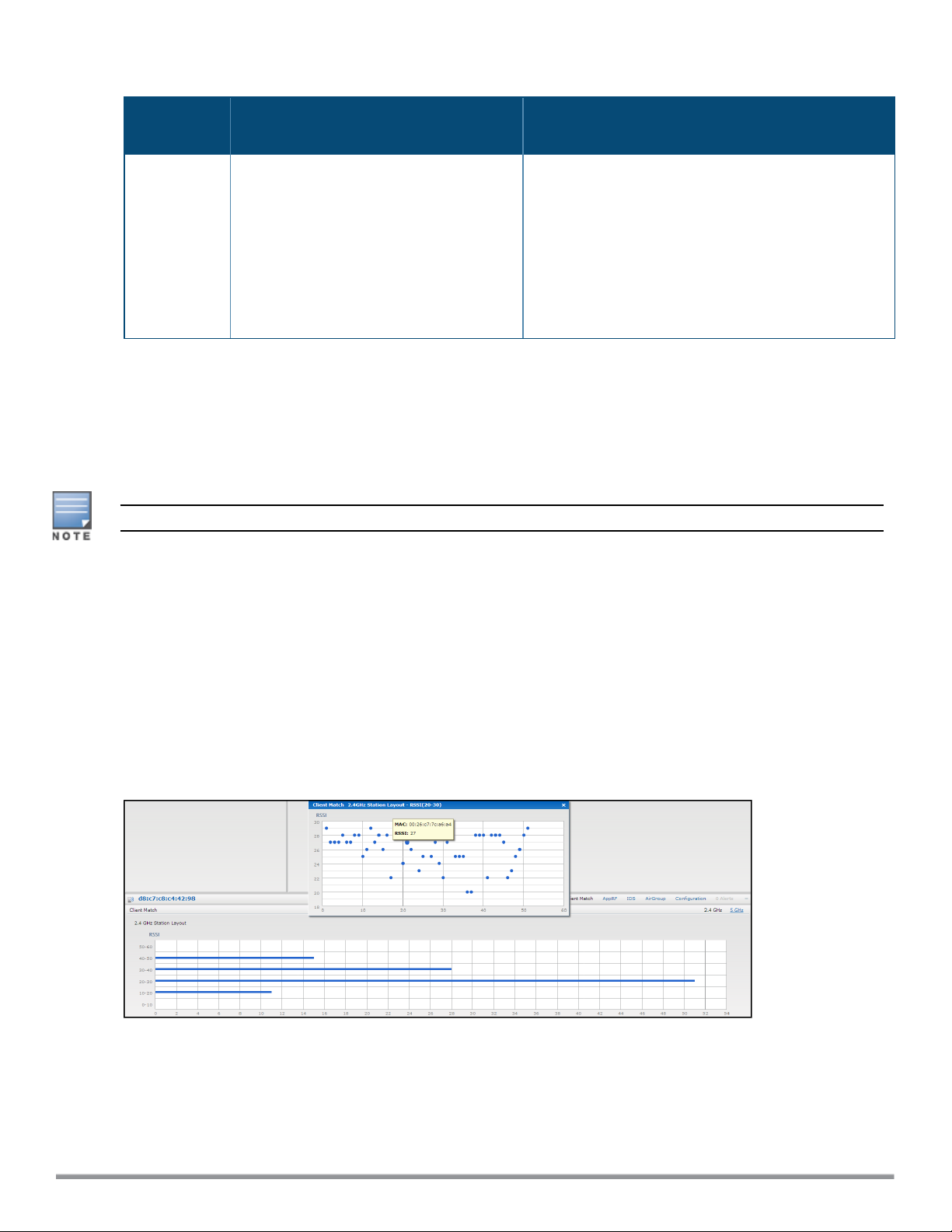
Table 13:
Client View — RF Trends Graphs and Monitoring Procedures
Graph
Name
Description Monitoring Procedure
incoming traffic is displayed in blue.
Incoming traffic is shown below the
median line.
To see an enlarged view, click the graph.
The enlarged view shows Last, Minimum,
Maximum, and Average statistics for the
incoming and outgoing traffic throughput of
the client for the last 15 minutes.
To see the exact throughput at a particular
time, move the cursor over the graph line.
For example, the graph shows 1.0 Kbps outgoing
traffic throughput for the client at 12:30 hours.
Mobility Trail
The Mobility Trail section displays the following mobility trail information for the selected client:
l Association Time— The time at which the selected client was associated with a particular W-IAP.
The Instant UI shows the client and W-IAP association over the last 15 minutes.
l Access Point— The W-IAP name with which the client was associated.
Mobility information about the client is reset each time it roams from one W-IAP to another.
Client Match
If client match is enabled, the Client Match link provides a graphical representation of radio map view of an AP and
the client distribution on an AP radio.
On clicking an access point in the Access Points tab and the Client Match link, a stations map view is displayed
and a graph is drawn with real-time data points for the AP radio. If the AP supports dual band, you can toggle
between 2.4GHz and 5 GHz links in the client match graph area to view the data. When you hover the mouse on the
graph, details such as RSSI, client match status, and the client distribution on channels are displayed.
The following figure shows the client distribution details for an AP radio.
Figure 20 Client Distribution on AP Radio
On clicking a client in the Clients tab and the Client Match link, a graph is drawn with real-time data points for an AP
radio map. When you hover the mouse on the graph, details such as RSSI, channel utilization details, and client
count on each channel are displayed.
Dell NetworkingW-Series Instant 6.4.0.2-4.1 | User Guide Instant User Interface | 66
Page 67

The following figure shows the client view heatmap for an AP radio:
Figure 21 Channel Availability Map for Clients
AppRF
The AppRF link displays the application traffic summary for W-IAPs and client devices. The AppRF link in the
activity panel is displayed only if AppRF visibility is enabled in the System window. For more information on
application visibility and AppRF charts, see Application Visibility on page 242.
Spectrum
The spectrum link (in the Access Point view) displays the spectrum data that is collected by a hybrid AP or by a WIAP that has enabled spectrum monitor. The spectrum data is not reported to the Virtual Controller.
The spectrum link displays the following:
l Device list - The device list display consists of a device summary table and channel information for active non
Wi-Fi devices currently seen by a spectrum monitor or hybrid AP radio.
l Channel Utilization and Monitoring - This chart provides an overview of channel quality across the spectrum. It
shows channel utilization information such as channel quality, availability, and utilization metrics as seen by a
spectrum monitor for the 2.4 GHz and 5 GHz radio bands. The first bar for each channel represents the
percentage of air time used by non Wi-Fi interference and Wi-Fi devices. The second bar indicates the channel
quality. A higher percentage value indicates better quality.
l Channel Details - When you move your mouse over a channel, the channel details or the summary of the 5 GHz
and 2.4 GHz channels as detected by a spectrum monitor are displayed. You can view the aggregate data for
each channel seen by the spectrum monitor radio, including the maximum AP power, interference and the Signalto-Noise and Interference Ratio (SNIR). Spectrum monitors display spectrum analysis data seen on all channels
in the selected band, and hybrid W-IAPs display data from the one channel they are monitoring.
For more information on spectrum monitoring, see Spectrum Monitor on page 309.
Alerts
Alerts are generated when a user encounters problems while accessing or connecting to a network. The alerts that
are generated can be categorized as follows:
l 802.11 related association and authentication failure alerts
l 802.1X related mode and key mismatch, server, and client time-out failure alerts
l IP address related failures - Static IP address or DHCP related alerts.
The following figure shows the contents of details displayed on clicking the Alerts link:
67 | Instant User Interface DellNetworking W-Series Instant 6.4.0.2-4.1 | User Guide
Page 68
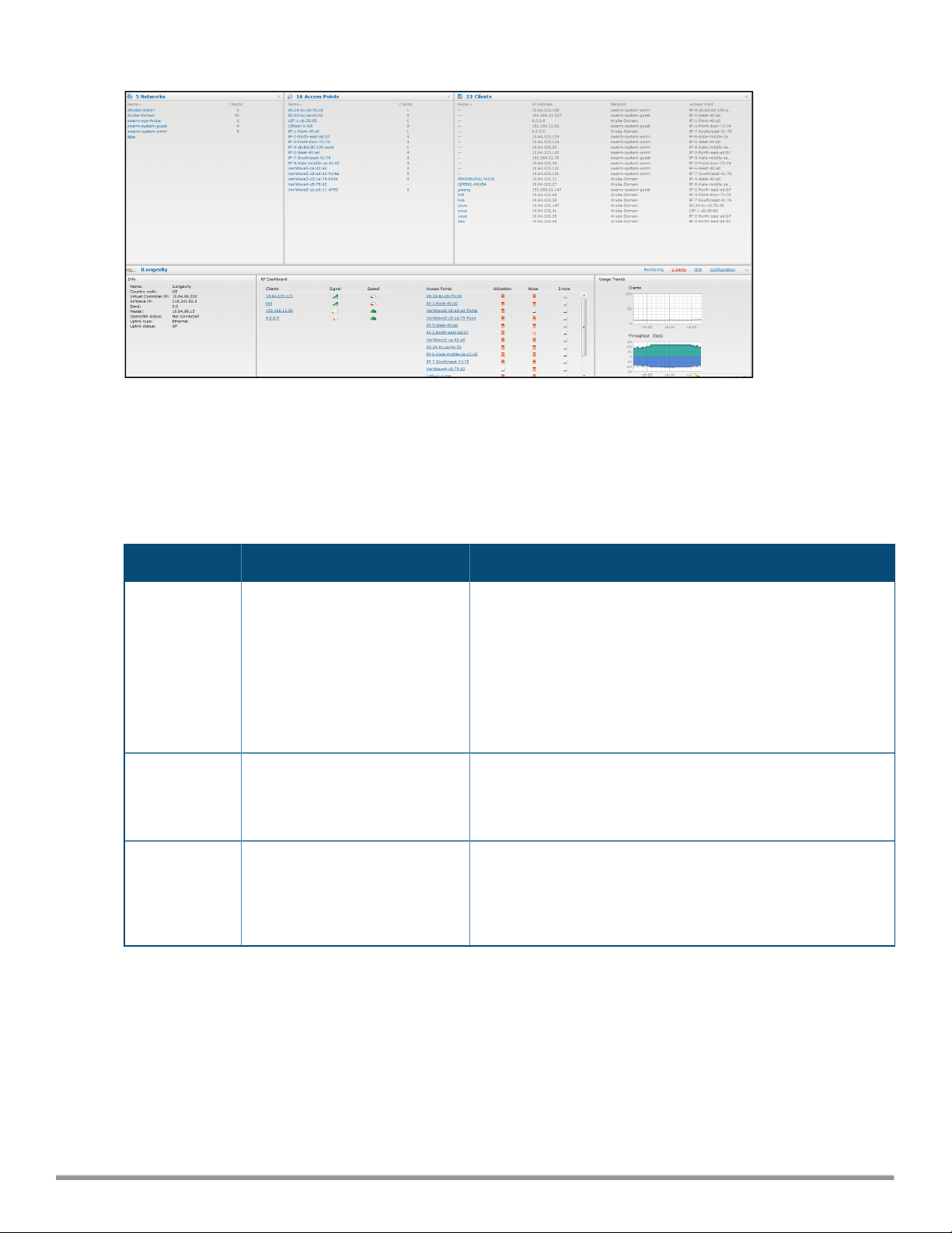
Figure 22 Alerts Link
The Alerts link displays the following types of alerts:
l Client Alerts
l Active Faults
l Fault History
Table 14:
Types of Alerts
Type of Alert Description Information Displayed
Client Alerts The Client alerts occur when
clients are connected to the
Instant network.
Active Faults The Active Faults occur in the
event of a system fault.
Fault History
The Fault Hist ory alerts occur in
the event of a system fault.
A client alert displays the following fields:
l Timestamp— Displays the time at which the client alert was
recorded.
l MAC address— Displays the MAC address of the client that
caused the alert.
l Description— Provides a short description of the alert.
l Access Points— Displays the IP address of the W-IAP to
which the client is connected.
l Details— Provides complete details of the alert.
An Active Faults consists of the following fields:
l Time— Displays the system time when an event occurs.
l Number— Indicates the number of sequence.
l Description— Displays the event details.
The Fault Hist ory displays the following information:
l Time— Displays the system time when an event occurs.
l Number— Indicates the number of sequence.
l Cleared by— Displays the module which cleared this fault.
l Description— Displays the event details.
The following figures show the client alerts, fault history, and active faults:
Dell NetworkingW-Series Instant 6.4.0.2-4.1 | User Guide Instant User Interface | 68
Page 69
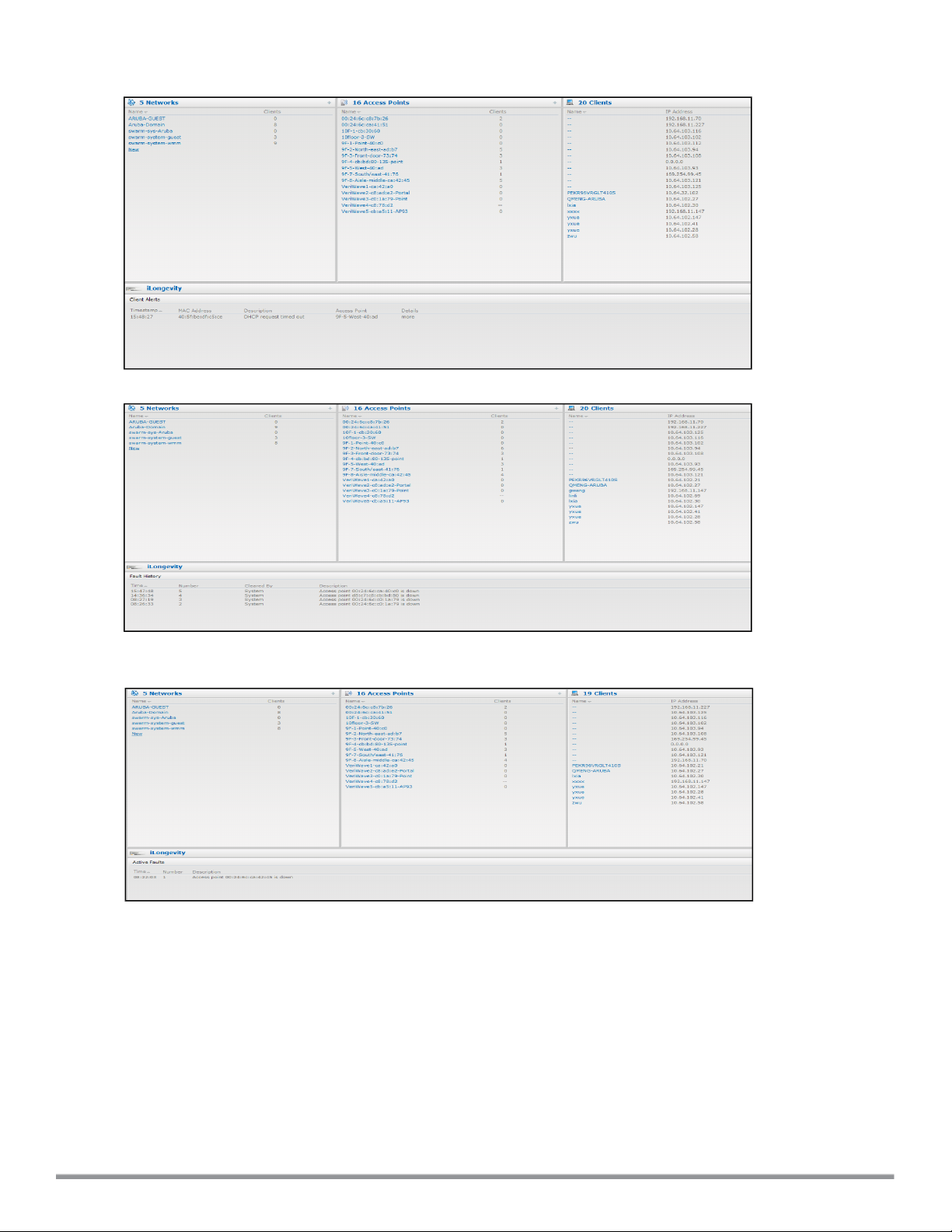
Figure 23 Client Alerts
Figure 24 Fault History
Figure 25 Active Faults
The following table displays a list of alerts that are generated in the W-IAP network:
69 | Instant User Interface DellNetworking W-Series Instant 6.4.0.2-4.1 | User Guide
Page 70

Table 15:
Alerts list
Type
Code
100101 Internal error The W-IAP has encountered
100102 Unknown SSID in
100103 Mismatched
100104 Unsupported 802.11 rate The W-IAP cannot allow this
100105 Maximum capacity reached
Description Details Corrective Actions
an internal error for this client.
The W-IAP cannot allow this
association request
authentication/encryption
setting
on W-IAP
client to associate, because
the association request
received contains an unknown
SSID.
The W-IAP cannot allow this
client to associate, because its
authentication or encryption
settings do not match W-IAP's
configuration.
client to associate because it
does not support the 802.11
rate requested by this client.
The W-IAP has reached
maximum capacity and cannot
accommodate any more
clients.
Contact the Dell customer support
team.
Identify the client and check its Wi-Fi
driver and manager software.
Ascertain the correct authentication or
encryption settings and try to associate
again.
Check the configuration on the W-IAP
to see if the desired rate can be
supported; if not, consider replacing
the W-IAP with another model that can
support the rate.
Consider expanding capacity by
installing additional W-IAPs or balance
load by relocating W-IAPs.
100206 Invalid MAC Address The W-IAP cannot
authenticate this client
because the client's MAC
address is not valid.
100307 Client blocked due to
repeated authentication
failures
100308 RADIUS server connection
failure
The W-IAP is temporarily
blocking the 802.1X
authentication request from
this client, because the
credentials provided are
rejected by the RADIUS server
too many times.
The W-IAP cannot
authenticate this client using
802.1X, because the RADIUS
server did not respond to the
authentication request.
This condition may be indicative of a
misbehaving client. Try to locate the
client device and check its hardware
and software.
Identify the client and check its 802.1X
credentials.
If the W-IAP is using the internal
RADIUS server, it is recommended that
you check the related configuration as
well as the installed certificate and
passphrase.
If the W-IAP is using an external
RADIUS server, check if there are any
issues with the RADIUS server and try
connecting again.
Dell NetworkingW-Series Instant 6.4.0.2-4.1 | User Guide Instant User Interface | 70
Page 71

Table 15:
Alerts list
Type
Code
100309 RADIUS server
Description Details Corrective Actions
authentication failure
The W-IAP cannot
authenticate this client using
Ascertain the correct authentication
credentials and log in again.
802.1X , because the RADIUS
server rejected the
authentication credentials
(password and so on)
provided by the client.
100410 Integrity check failure in
encrypted message
The W-IAP cannot receive
data from this client , because
Check the encryption setting on the
client and on the W-IAP.
the integrity check of the
received message (MIC) has
failed.
100511 DHCP request timed out This client did not receive a
response to its DHCP request
Check the status of the DHCP server in
the network.
in time.
IDS
The IDSlink displays a list of foreign APs and foreign clients that are detected in the network. It consists of the
following sections:
l Foreign Access Points Detected— Lists the APs that are not controlled by the Virtual Controller. The following
information is displayed for each foreign AP:
n MAC address— Displays the MAC address of the foreign AP.
n Network— Displays the name of the network to which the foreign AP is connected.
n Classification— Displays the classification of the foreign AP, for example, Interfering W-IAP or Rogue W-IAP.
n Channel— Displays the channel in which the foreign AP is operating.
n Type— Displays the Wi-Fi type of the foreign AP.
n Last seen— Displays the time when the foreign AP was last detected in the network.
n Where— Provides information about the W-IAP that detected the foreign AP. Click the pushpin icon to view
the information.
l Foreign Clients Detected— Lists the clients that are not controlled by the Virtual Controller. The following
information is displayed for each foreign client:
n MAC address— Displays the MAC address of the foreign client.
n Network— Displays the name of the network to which the foreign client is connected.
n Classification— Displays the classification of the foreign client: Interfering client.
n Channel— Displays the channel in which the foreign client is operating.
n Type— Displays the Wi-Fi type of the foreign client.
n Last seen— Displays the time when the foreign client was last detected in the network.
n Where— Provides information about the W-IAP that detected the foreign client. Click the pushpin icon to view
the information.
The following figure shows an example for the intrusion detection log.
71 | Instant User Interface DellNetworking W-Series Instant 6.4.0.2-4.1 | User Guide
Page 72
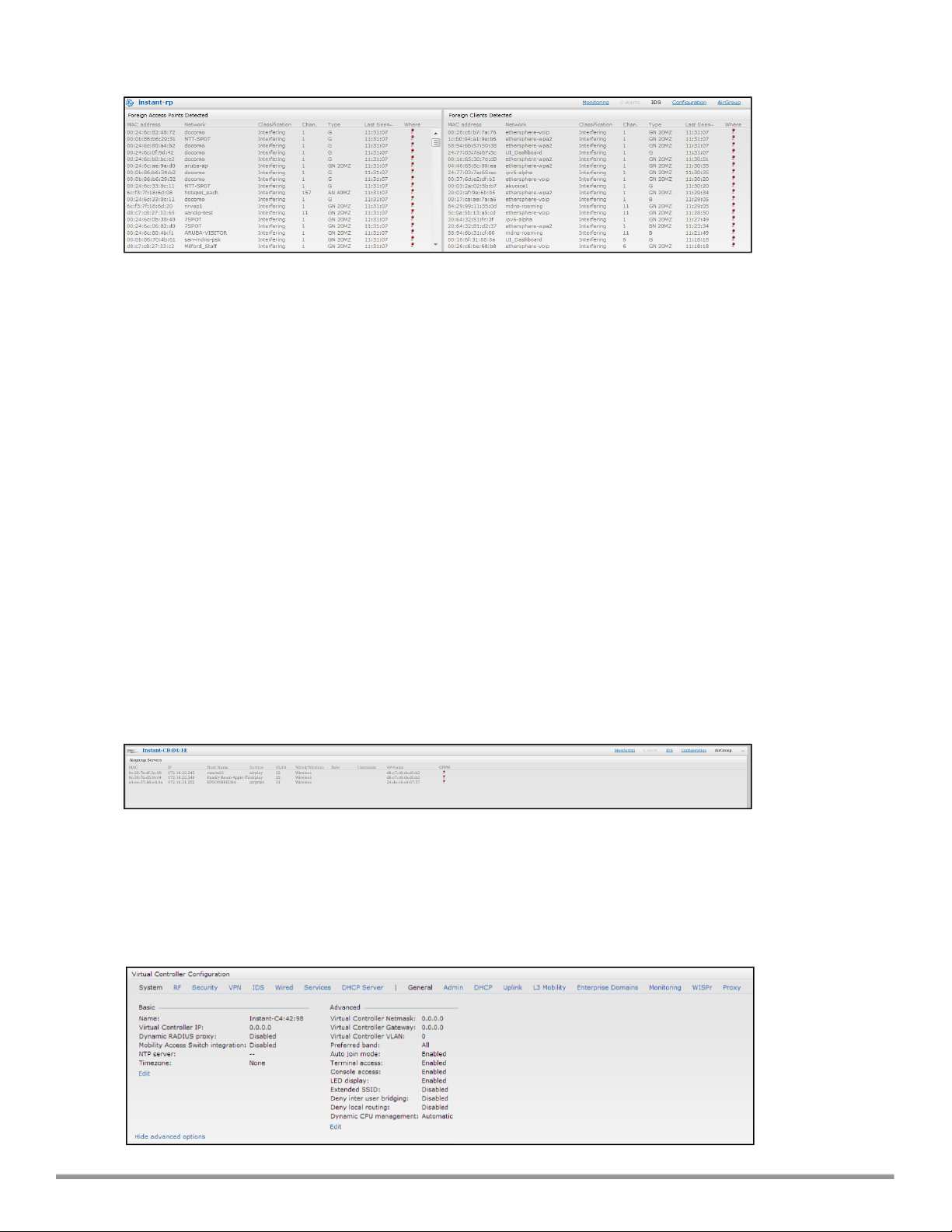
Figure 26 Intrusion Detection
For more information on the intrusion detection feature, see Intrusion Detection on page 296.
AirGroup
This AirGroup link provides an overall view of your AirGroup configuration. Click each field to view or edit the
settings.
l MAC — Displays the MAC address of the AirGroup servers.
l IP — Displays the IP address of the AirGroup servers.
l Host Name — Displays the machine name or hostname of the AirGroup servers.
l Service— Displays the type of the services such as AirPlay or AirPrint.
l VLAN— Displays VLANdetails of the AirGroup servers.
l Wired/Wireless — Displays if the AirGroup server is connected via wired or wireless interface.
l Role—Displays the user role if the server is connected through 802.1X authentication. If the server is connected
through PSK or open authentication, this field is blank.
l Group—Displays the group.
l CPPM— By clicking on this, you get details of the registered rules in ClearPass Policy Manager (CPPM) for this
server.
l MDNS Cache— By clicking on this, you receive MDNS record details of a particular server.
The following figure shows the AirGroup server details available on clicking the AirGroup link:
Figure 27 AirGroup Link
Configuration
The Configuration link provides an overall view of your Virtual Controller, Access Points, and WLAN
SSIDconfiguration. The following figure shows the Virtual Controller configuration details displayed on clicking the
Configuration link.
Figure 28 Configuration Link
Dell NetworkingW-Series Instant 6.4.0.2-4.1 | User Guide Instant User Interface | 72
Page 73

W-AirWave Setup
W-AirWave is a solution for managing rapidly changing wireless networks. When enabled, W-AirWave allows you to
manage the Instant network. For more information on W-AirWave, see Managing a W-IAP from W-AirWave on page
275. The W-AirWave status is displayed at the bottom of the Instant main window. If the W-AirWave status is Not
Set Up, click the Set Up Now link to configure W-AirWave. The System window is displayed with Admin tab
selected.
Pause/Resume
The Pause/Resume link is located at the bottom right corner of the Instant main window.
Click the Pause link to pause the automatic refreshing of the Instant U after every 15 seconds by default. The
Instant UI is automatically refreshed after every 15 seconds by default. When the automatic refreshing is paused,
the Pause link changes to Resume. Click the Resume link to resume automatic refreshing.
Automatic refreshing allows you to get the latest information about the network and network elements. You can use
the Pause link when you want to analyze or monitor the network or a network element, and therefore do not want the
user interface to refresh.
Views
Depending on the link or tab that is clicked, the Instant displays information about the Virtual Controller, Wi-Fi
networks, W-IAPs, or the clients in the Info section. The views on the Instant main window are classified as follows:
l Virtual Controller view— The Virtual Controller view is the default view. This view allows you to monitor the
Instant network. This view allows you to monitor the Instant network.
l The following Instant UI elements are available in this view:
n Tabs— Networks, Access Points, and Clients. For detailed information about the tabs, see Tabs on page 45.
n Links— Monitoring, Client Alerts, and IDS. The Spectrum link is visible if you have configured the W-IAP as a
spectrum monitor. These links allow you to monitor the Instant network. For more information about these
links, see Monitoring on page 57, IDS on page 71, Alerts on page 67, and Spectrum Monitor on page 309.
l Network view— The Network view provides information that is necessary to monitor a selected wireless network.
All Wi-Fi networks in the Instant network are listed in the Networks tab. Click the name of the network that you
want to monitor. Network view for the selected network is displayed.
l Instant Access Point view— The Instant Access Point view provides information that is necessary to monitor a
selected W-IAP. All W-IAPs in the Instant network are listed in the Access Points tab. Click the name of the WIAP that you want to monitor. Access Point view for that W-IAP is displayed.
l Client view— The Client view provides information that is necessary to monitor a selected client. In the Client
view, all the clients in the Instant network are listed in the Clients tab. Click the IP address of the client that you
want to monitor. Client view for that client is displayed.
For more information on the graphs and the views, see Monitoring on page 57.
73 | Instant User Interface DellNetworking W-Series Instant 6.4.0.2-4.1 | User Guide
Page 74
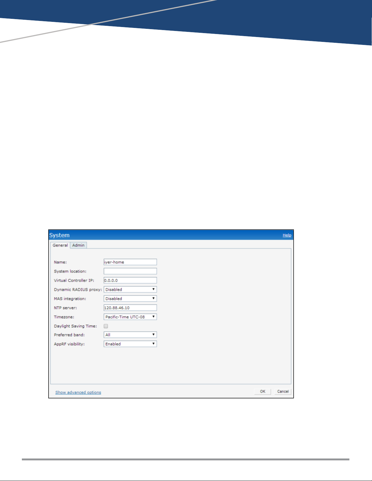
Chapter 5
Initial Configuration Tasks
This chapter describes the general configuration tasks to perform when a W-IAP is set up.
l Basic Configuration Tasks on page 74
l Additional Configuration Tasks on page 78
Basic Configuration Tasks
This section describes the following basic configuration tasks that can be performed in the System>General tab
after a W-IAP is set up:
l Modifying the W-IAP Name on page 74
l Updating Location Details of a W-IAP on page 75
l Configuring Virtual Controller IP Address on page 76
l Configuring Timezone on page 76
l Configuring a Preferred Band on page 75
l Configuring an NTP Server on page 76
l Enabling AppRF Visibility on page 77
The following figure shows an example for the basic configuration settings under the System>General tab:
For information on Dynamic RADIUS proxy configuration, see Configuring Authentication Servers on page 157.
Modifying the W-IAP Name
You can change the name of a W-IAP by using the Instant UI or CLI.
Dell NetworkingW-Series Instant 6.4.0.2-4.1 | User Guide InitialConfiguration Tasks | 74
Page 75

In the Instant UI
1. Navigate to System>General.
2. Specify the name of W-IAP in the Name text box.
3. Click OK.
In the CLI
To change the name:
(Instant AP)# name <name>
Updating Location Details of a W-IAP
You can update the physical location details of a W-IAP by using the Instant UI or CLI. The system location details
are used for retrieving information through the SNMP
In the Instant UI
To update location details:
1. Navigate to System>General.
2. Specify the location of a W-IAP in the System location text box.
3. Click OK.
sysLocation
MIB object.
In the CLI
To update location details of a W-IAP:
(Instant AP)(config)# syslocation <location-name>
(Instant AP)(config)# end
(Instant AP)# commit apply
Configuring a Preferred Band
You can configure a preferred band for a W-IAP by using the Instant UI or the CLI.
In the Instant UI
1. Navigate to System>General.
2. Select 2.4 GHz, 5 GHz or All from the Preferred band drop-down list for single-radio access points.
3. Click OK.
Reboot the W-IAP after configuring the radio profile for the changes to affect.
In the CLI
To configure a preferred band:
(Instant AP)(config)# rf-band <band>
(Instant AP)(config)# end
(Instant AP)# commit apply
75 | InitialConfiguration Tasks Dell Networking W-Series Instant 6.4.0.2-4.1 | User Guide
Page 76

Configuring Virtual Controller IP Address
You can specify a single static IP address that can be used to manage a multi-AP Instant network. This IP address
is automatically provisioned on a shadow interface on the W-IAP that takes the role of a Virtual Controller. When a
W-IAP becomes a Virtual Controller, it sends three Address Resolution Protocol (ARP) messages with the static IP
address and its MAC address to update the network ARP cache.
You can configure the Virtual Controller name and IP address using the Instant UI or CLI.
In the Instant UI
1. Navigate to System>General.
2. Enter the IP address in Virtual Controller IP.
3. Click OK.
In the CLI
To configure the Virtual Controller Name and IP address:
(Instant AP)(config)# virtual-controller-ip <IP-address>
(Instant AP)(config)# end
(Instant AP)# commit apply
Configuring Timezone
You can configure time zone in which the W-IAP must operate by using the Instant or the CLI.
In the Instant UI
To configure time zone:
1. Navigate to System>General.
2. Select a time zone from the Timezone drop-down list.
You can enable daylight saving time (DST) on W-IAPs if the time zone you selected supports the
daylight saving time. If the Time Zone selected does not support DST, the Daylight Saving Time
option is not displayed. When enabled, the Daylight saving time ensures that the W-IAPs reflect the
seasonal time changes in the region they serve.
3. To enable daylight saving time, select the Daylight Saving Time checkbox.
4. Click OK.
In the CLI
To configure time zone:
(Instant AP)(config)# clock timezone <name> <hour-offset> <minute-offset>
(Instant AP)(config)# clock summer-time <timezone> recurring <start-week> <start-day> <startmonth> <start-hour> <end-week> <end-day> <end-month> <end-hour>
(Instant AP)(config)# end
(Instant AP)# commit apply
Configuring an NTP Server
To facilitate communication between various elements in a network, time synchronization between the elements and
across the network is critical. Time synchronization allows you to:
l Trace and track security gaps, network usage, and troubleshoot network issues.
l Validate certificates
l Map an event on one network element to a corresponding event on another.
Dell NetworkingW-Series Instant 6.4.0.2-4.1 | User Guide InitialConfiguration Tasks | 76
Page 77

l Maintain accurate time for billing services and similar.
The Network Time Protocol (NTP) helps obtain the precise time from a serverand regulate the local time in each
network element. Connectivity to a valid NTP server is required to synchronize the W-IAP clock to set the correct
time. If NTP server is not configured in the W-IAP network, a W-IAP reboot may lead to variation in time data.
By default, the W-IAP tries to connect to pool.ntp.org to synchronize time. A different NTP server can be
configured either from the UI. It can also be provisioned through the DHCP option 42. If the NTP server is
configured, it takes precedence over the DHCP option 42 provisioned value. The NTP server provisioned through the
DHCP option 42 is used if no server is configured. The default server pool.ntp.org is used if no NTP server is
configured or provisioned through DHCP option 42.
Reboot the AP to apply the NTP server configuration.
You can configure an NTP server by using the Instant UI or the CLI.
In the Instant UI
To configure an NTP server:
1. Navigate to System>General.
2. Enter the IP address or the URL (domain name) of the NTP server in the NTP Server text box.
3. Click OK.
4. Reboot the W-IAP.
In the CLI
To configure an NTP server:
(Instant AP)(config)# ntp-server <name>
(Instant AP)(config)# end
(Instant AP)# commit apply
To check the NTP status and association, run the show clock and show process commands.
Enabling AppRF Visibility
If your W-IAP supports the AppRF feature, you can enable AppRF visibility to view the AppRF statistics for a W-IAP
or the clients associated with a W-IAP. For more information on the procedure for enabling AppRF visualization, see
Enabling Application Visibility on page 241.
Changing Password
You can update your password details by using the Instant UI or the CLI.
In the Instant UI
1. Navigate to System>Admin.
2. Under Local, provide a new password that you would like the admin users to use.
3. Click OK.
In the CLI
To change password for the admin user:
(Instant AP)(config)# mgmt-user <username> [password]
(Instant AP)(config)# end
(Instant AP)# commit apply
77 | InitialConfiguration Tasks Dell Networking W-Series Instant 6.4.0.2-4.1 | User Guide
Page 78
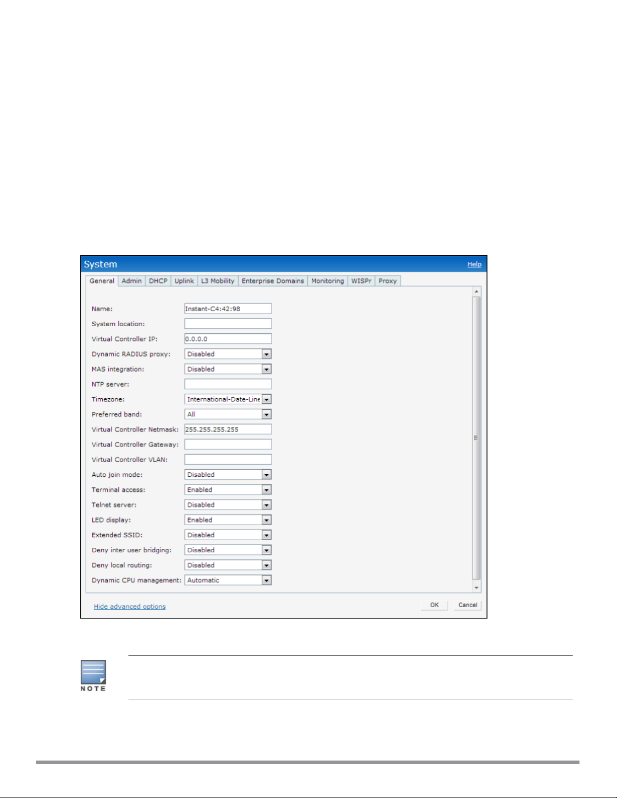
Additional Configuration Tasks
This section describes the following additional tasks that can be performed after a W-IAP is set up:
l Configuring Virtual Controller VLAN on page 78
l Configuring Auto Join Mode on page 79
l Configuring Terminal Access on page 80
l Configuring Console Access on page 80
l Configuring LED Display on page 81
l Configuring Additional WLAN SSIDs on page 81
l Preventing Inter-user Bridging on page 82
l Preventing Local Routing between Clients on page 82
l Enabling Dynamic CPU Management on page 83
The following figure shows the additional configuration options available under the System>General tab:
Configuring Virtual Controller VLAN
The IP configured for the Virtual Controller can be in the same subnet as W-IAP or can be in a different
subnet. Ensure that you configure the Virtual Controller VLAN, gateway, and subnet mask details only
if the Virtual Controller IP is in a different subnet.
You can configure the Virtual Controller VLAN by using Instant UI or CLI.
Dell NetworkingW-Series Instant 6.4.0.2-4.1 | User Guide InitialConfiguration Tasks | 78
Page 79
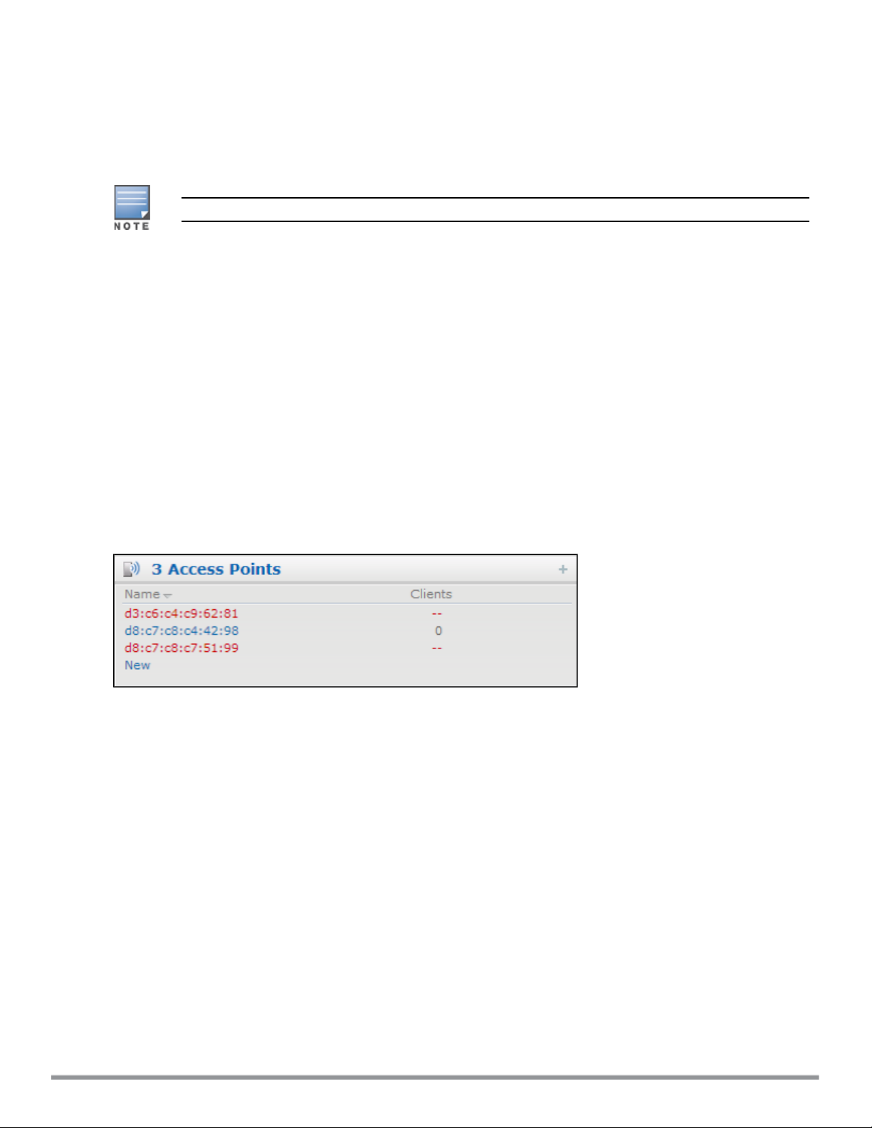
In the Instant UI
1. Navigate to System>General> Show advanced options. The advanced options are displayed.
2. Enter subnet mask details in Virtual Controller Netmask.
3. Enter a gateway address in Virtual Controller Gateway.
4. Enter Virtual Controller VLAN in Virtual Controller VLAN.
Ensure that Virtual Controller VLAN is not the same as native VLAN of the W-IAP.
5. Click OK.
In the CLI
To configure the Virtual Controller Name and IP address:
(Instant AP)(config)# virtual-controller-vlan <vcvlan> <vcmask> <vcgw>
(Instant AP)(config)# end
(Instant AP)# commit apply
Configuring Auto Join Mode
The auto join mode feature allows W-IAPs to automatically discover the Virtual Controller and join the network.
The Auto Join Mode feature is enabled by default. If the auto join mode feature is disabled, a New link is displayed
in the Access Points tab. Click this link to add W-IAPs to the network. If this feature is disabled, the inactive WIAPs are displayed in red as shown in the following figure:
Figure 29 Inactive W-IAPs
Enabling or Disabling Auto Join Mode
You can enable or disable auto join mode by using the Instant UI or CLI.
In the Instant UI
To enable or disable auto join mode:
1. Navigate to System>General>Show advanced options.
2. Select Disabled or Enabled from the Auto join mode drop-down list to deny or allow APs to join the network.
3. Click OK.
In the CLI
To disable auto join mode:
(Instant AP)(config)# no allow-new-aps
(Instant AP)(config)# end
(Instant AP)# commit apply
To enable auto join mode:
(Instant AP)(config)# allow-new-aps
79 | InitialConfiguration Tasks Dell Networking W-Series Instant 6.4.0.2-4.1 | User Guide
Page 80

(Instant AP)(config)# end
(Instant AP)# commit apply
Configuring Terminal Access
When terminal access is enabled, you can access the Instant CLI through SSHor Telnet server. The terminal
access is enabled by default.
You can enable or disable terminal access to a W-IAP by using the Instant UI or CLI.
In the Instant UI
1. Navigate to System>General>Show advanced options.
2. Select Disabled or Enabled from the Terminal access drop-down list.
3. To enable Telnet server based access, select Enabled from the Telnet server drop-down list.
4. Click OK.
In the CLI
To enable terminal access:
(Instant AP)(config)# terminal-access
(Instant AP)(config)# end
(Instant AP)# commit apply
To enable access to the Instant CLI through Telnet:
(Instant AP)(config) # telnet-server
(Instant AP)(config)# end
(Instant AP)# commit apply
Configuring Console Access
You can access a W-IAP console through a serial port to configure or debug system errors. You can enable or
disable console access to a W-IAP through the Instant UI or CLI.
In the Instant UI
1. Navigate to System>General>Show advanced options.
2. Select Disabled or Enabled from the Console access drop-down list. By default, the console access is
enabled. When disabled, the W-IAP console cannot be accessed through the serial port.
3. Click OK.
In the CLI
To enable console access:
(Instant AP)(config)# console
(Instant AP)(console)# enable
(Instant AP)(console)# end
(Instant AP)# commit apply
To disable console access:
(Instant AP)(config)# console
(Instant AP)(console)# disable
(Instant AP)(console)# end
(Instant AP)# commit apply
To view the console settings:
(Instant AP)# show console-settings
Dell NetworkingW-Series Instant 6.4.0.2-4.1 | User Guide InitialConfiguration Tasks | 80
Page 81
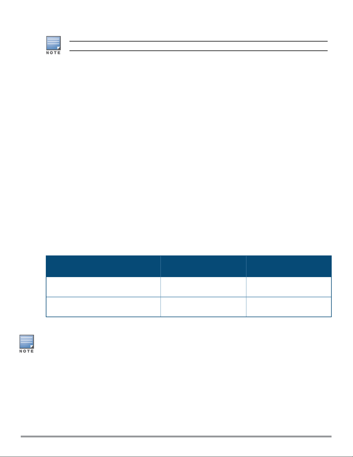
Configuring LED Display
The LED display is always in the Enabled mode during the a W-IAP reboot.
You can enable or disable LEDDisplay for a W-IAP using the Instant UI or CLI.
In the Instant UI
To enable or disable LEDdisplay for all W-IAPs in a cluster, perform the following steps:
1. Navigate to System > General > Show advanced options.
2. From the LED Display drop-down list, select Enabled to enable LED display or Disabled to turn off the LED
display.
3. Click OK.
In the CLI
To enable LEDdisplay:
(Instant AP)(config)# led-off
(Instant AP)(config)# end
(Instant AP)# commit apply
To disable LEDdisplay:
(Instant AP)(config)# no led-off
(Instant AP)(config)# end
(Instant AP)# commit apply
Configuring Additional WLAN SSIDs
The number of SSIDs allowed on each W-IAP depends on the W-IAP platform. The following table describes the
number of SSIDs supported on each platform:
W-IAP Platform
IAP-175P/175AC, W-IAP104/105, and WIAP108/109
All other W-IAPs (excluding IAP-175P/175AC,
W-IAP104/105, and W-IAP108/109)
No. of SSIDs supported with
Extended SSID disabled
6 8
14 16
Enabling the Extended SSID
Extended SSID is enabled by default in the factory default settings of APs. This disables mesh in the factory default
settings.
You can configure additional SSIDs by using the Instant UI or CLI.
In the Instant UI
1. Navigate to System>General>Show advanced options link.
2. In the General tab, select Enabled from the Extended SSID drop-down list.
3. Click OK.
No. of SSIDs supported with
Extended SSID enabled
81 | InitialConfiguration Tasks Dell Networking W-Series Instant 6.4.0.2-4.1 | User Guide
Page 82

4. Reboot the W-IAP to apply the changes. After you enable the option and reboot the W-IAP, the Wi-Fi and mesh
links are disabled automatically.
In the CLI
To enable the extended SSIDs:
(Instant AP)(config)# extended-ssid
(Instant AP)(config)# end
(Instant AP)# commit apply
Preventing Inter-user Bridging
If you have security and traffic management policies defined in upstream devices, you can disable bridging traffic
between two clients connected to the same AP on the same VLAN. When inter-user bridging is denied, the clients
can connect to the Internet but cannot communicate with each other, and the bridging traffic between the clients is
sent to the upstream device to make the forwarding decision.
You can disable inter-user bridging through the Instant UI or CLI.
In the Instant UI
To prevent inter-user bridging:
1. Navigate to System>General>Show advanced options.
2. From the Deny inter user bridging drop-down list, select Enabled to prevent traffic between two clients
connected to a W-IAP on the same VLANs.
3. Click OK.
In the CLI
To deny inter-user bridging:
(Instant AP)(config)# deny-inter-user-bridging
(Instant AP)(config)# end
(Instant AP)# commit apply
To deny inter-user bridging for the WLAN SSID clients:
(Instant AP)(config)# wlan ssid-profile <ssid-profile>
(Instant AP) (SSID Profile <ssid-profile>)# deny-inter-user-bridging
(Instant AP) (SSID Profile <ssid-profile>)# end
(Instant AP)# commit apply
Preventing Local Routing between Clients
If you have security and traffic management policies defined in upstream devices, you can disable routing traffic
between two clients connected to the same W-IAP on different VLANs. When local routing is disabled, the clients
can connect to the Internet but cannot communicate with each other, and the routing traffic between the clients is
sent to the upstream device to make the forwarding decision.
You can disable local routing through the Instant UI or CLI.
In the Instant UI
To disable local routing:
1. Navigate to System>General>Show advanced options.
2. From the Deny local routing drop-down list, select Enabled to prevent local routing traffic between two clients
connected to a W-IAP on different VLANs.
3. Click OK.
Dell NetworkingW-Series Instant 6.4.0.2-4.1 | User Guide InitialConfiguration Tasks | 82
Page 83

In the CLI
To disable local routing:
(Instant AP)(config)# deny-local-routing
(Instant AP)(config)# end
(Instant AP)# commit apply
To deny local routing for the WLAN SSID clients:
(Instant AP)(config)# wlan ssid-profile <ssid-profile>
(Instant AP) (SSID Profile <ssid-profile>)# deny-local-routing
(Instant AP) (SSID Profile <ssid-profile>)# end
(Instant AP)# commit apply
Enabling Dynamic CPU Management
W-IAPs perform various functions such as wireless client connectivity and traffic flows, wired client connectivity
and traffic flows, wireless security, network management, and location tracking. Like with any network element, a
W-IAP can be subject to heavy loads. In such a scenario, it is important to prioritize the platform resources across
different functions. Typically, the W-IAPs manage resources automatically in real-time. However, under special
circumstances, if dynamic resource management needs to be enforced or disabled altogether, the dynamic CPU
management feature settings can be modified.
You can configure the dynamic CPU management feature by using the Instant UI or CLI.
In the Instant UI
To enable or disable the management plane protection:
1. Click System > General>Show Advanced Options.
2. Select any of the following options from the Dynamic CPU Management drop-down list.
n Automatic — When selected, the CPU management is enabled or disabled automatically during run-time. This
decision is based on real-time load calculations taking into account all different functions that the CPU needs
to perform. This is the default and recommended option.
n Always disabled on all APs — When selected, this setting manually disables CPU management on all APs,
typically for small networks. This setting protects user experience.
n Always enabled on APs — When selected, the client and network management functions are protected. This
setting helps in large networks with high client density.
3. Click OK.
In the CLI
(Instant AP)(config)# dynamic-cpu-mgmt {auto| enable| disable}
83 | InitialConfiguration Tasks Dell Networking W-Series Instant 6.4.0.2-4.1 | User Guide
Page 84

Chapter 6
Customizing W-IAP Settings
This chapter describes the procedures for configuring settings that are specific to a W-IAP in the cluster.
l Modifying the W-IAP Hostname on page 84
l Configuring Zone Settings on a W-IAP on page 84
l Specifying a Method for Obtaining IP Address on page 85
l Configuring External Antenna on page 86
l Configuring Radio Profiles for a W-IAP on page 87
l Configuring Uplink VLANfor a W-IAP on page 88
l Master Election and Virtual Controller on page 89
l Adding a W-IAP to the Network on page 91
l Removing a W-IAP from the Network on page 91
Modifying the W-IAP Hostname
You can change the hostname of a W-IAP through the Instant UI or CLI.
In the Instant UI
1. In the Access Points tab, click the W-IAP you want to rename. The edit link is displayed.
2. Click the edit link. The edit window for modifying W-IAP details is displayed.
3. Edit the W-IAP name in Name. You can specify a name of up to 32 ASCII characters.
4. Click OK.
In the CLI
To change the name:
(Instant AP)# hostname <name>
Configuring Zone Settings on a W-IAP
All APs in a cluster use the same SSID configuration including master and slave W-IAPs. However, if you want to
assign an SSID to a specific W-IAP, you can configure zone settings for a W-IAP.
The following constraints apply to the AP zone configuration:
l A W-IAP can belong to only one zone and only one zone can be configured on an SSID.
l If an SSID belongs to a zone, all W-IAPs in this zone can broadcast this SSID. If no W-IAP belongs to the zone
configured on the SSID, the SSID is not broadcast.
l If an SSID does not belong to any zone, all W-IAPs can broadcast this SSID.
You can add an AP zone by through the UI or CLI.
For the SSID to be assigned to a W-IAP, the same zone details must be configured on the SSID. For more
information on SSID configuration, see Configuring WLAN Settings for an SSID Profile on page 93.
Dell NetworkingW-Series Instant 6.4.0.2-4.1 | User Guide Customizing W-IAP Settings | 84
Page 85
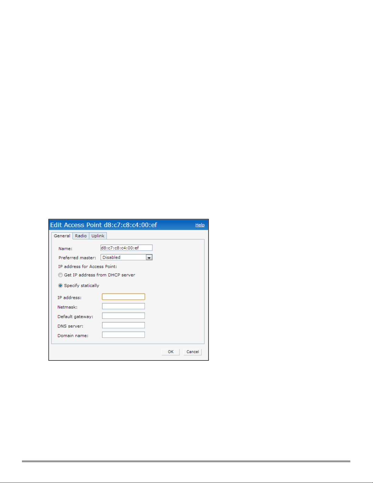
In the Instant UI
1. In the Access Points tab, click the W-IAP for which you want to set the zone. The edit link is displayed.
2. Click the edit link. The edit window for modifying W-IAP details is displayed.
3. Specify the AP zone in Zone.
4. Click OK.
In the CLI
To change the name:
(Instant AP)# zone <name>
Specifying a Method for Obtaining IP Address
You can either specify a static IP address or allow the W-IAP to obtain an IP address from the DHCP server. By
default, the W-IAPs obtain IP address from the DHCP server. You can specify a static IP address for the W-IAP by
using the Instant UI or CLI.
In the Instant UI
1. In the Access Points tab, click the W-IAP to modify. The edit link is displayed.
2. Click the edit link. The edit window for modifying the W-IAP details is displayed.
Figure 30 Configuring W-IAP Settings
3. Select Specify statically option to specify a static IP address. The following fields are displayed:
a. Enter the new IP address for the W-IAP in the IP address text box.
b. Enter the subnet mask of the network in the Netmask text box.
c. Enter the IP address of the default gateway in the Default gateway text box.
d. Enter the IP address of the DNS server in the DNS server text box.
e. Enter the domain name in the Domain name text box.
4. Click OK and reboot the W-IAP.
85 | Customizing W-IAP Settings Dell Networking W-Series Instant 6.4.0.2-4.1 | User Guide
Page 86

In the CLI
To configure a static IP address:
(Instant AP)# ip-address <IP-address> <subnet-mask> <NextHop-IP> <DNS-IP-address> <domainname>
Configuring External Antenna
If your W-IAP has external antenna connectors, you need to configure the transmit power of the system. The
configuration must ensure that the system’s Equivalent Isotropically Radiated Power (EIRP) is in compliance with
the limit specified by the regulatory authority of the country in which the W-IAP is deployed. You can also measure or
calculate additional attenuation between the device and antenna before configuring the antenna gain. To know if your
AP device supports external antenna connectors, see the
EIRP and Antenna Gain
The following formula can be used to calculate the EIRP limit related RF power based on selected antennas
(antenna gain) and feeder (Coaxial Cable loss):
EIRP = Tx RF Power (dBm)+GA (dB) - FL (dB)
The following table describes this formula:
Install Guide
that is shipped along with the AP device.
Table 16:
Formula Element Description
EIRP Limit specific for each country of deployment
Tx RF Power RF power measured at RF connector of the unit
GA Antenna gain
FL Feeder loss
Formula Variable Definitions
Example
For example, the maximum gain that can be configured on a W-IAP134 with AP-ANT-1F dual-band and omnidirectional antenna is as follows:
Table 17:
Frequency Band Gain (dBi)
2.4-2.5 GHz 2.0dBi
4.9–5.875GHz 5.0dBi
Maximum Antenna Gains
For information on antenna gain recommended by the manufacturer, see dell.com/support.
Configuring Antenna Gain
You can configure antenna gain for APs with external connectors using Instant UI or CLI.
In the Instant UI
1. Navigate to the Access Point tab, select the access point to configure and then click edit.
Dell NetworkingW-Series Instant 6.4.0.2-4.1 | User Guide Customizing W-IAP Settings | 86
Page 87

2. In the Edit Access Point window, select External Antenna to configure the antenna gain value. This option is
available only for access points that support external antennas, for example, W-IAP134.
3. Enter the antenna gain values in dBm for the 2.4GHz and 5GHz bands.
4. Click OK.
In the CLI
To configure external antenna for 5 GHz frequency:
(Instant AP)# a-external-antenna <dBi>
To configure external antenna for 2,4 GHz frequency:
(Instant AP)# g-external-antenna <dBi>
Configuring Radio Profiles for a W-IAP
You can configure a radio profile on a W-IAP either manually or by using the Adaptive Radio Management (ARM)
feature.
Adaptive Radio Management (ARM) is enabled on Instant by default. It automatically assigns appropriate channel
and power settings for the W-IAPs. For more information on ARM, see Adaptive Radio Management on page 232.
Configuring ARMAssigned Radio Profiles for a W-IAP
To enable ARM assigned radio profiles:
1. In the Access Points tab, click the W-IAP to modify. The edit link is displayed.
2. Click the edit link. The edit window for modifying W-IAP details is displayed.
3. Click the Radio tab. The Radio tab details are displayed.
4. Ensure that an appropriate mode is selected.
5. Select the Adaptive radio management assigned option under the bands that are applicable to the W-IAP
configuration.
6. Click OK.
Configuring Radio Profiles Manually for W-IAP
When radio settings are assigned manually by the administrator, the ARMis disabled.
To manually configure radio settings:
1. In the Access Points tab, click the AP for which you want to enable ARM. The edit link is displayed.
2. Click the edit link. The Edit Access Point window is displayed.
3. Click the Radio tab.
4. Ensure that an appropriate mode is selected.
By default the channel and power for an AP are optimized dynamically using Adaptive Radio Management
(ARM). You can override ARM on the 2.4 GHz and 5 GHz bands and set the channel and power manually if
desired. The following table describes various configuration modes for an AP:
87 | Customizing W-IAP Settings Dell Networking W-Series Instant 6.4.0.2-4.1 | User Guide
Page 88

Table 18:
W-IAP Radio Modes
Mode Description
Access In Access mode, the AP serves clients, while also monitoring for rogue APs in the
background.
If the Access mode is selected, perform the following actions:
1. Select Administrator assigned in 2.4 GHz and 5 GHz band sections.
2. Select appropriate channel number from the Channel drop-down list for both 2.4
GHz and 5 GHz band sections.
3. Enter appropriate transmit power value in the Transmit power text box in 2.4 GHz
and 5 GHz band sections.
Monitor In Monitor mode, the AP acts as a dedicated monitor, scanning all channels for rogue
APs and clients. You can set one radio on the Monitor mode and the other radio on
access mode, so that the clients can use one radio when the other one is in the Air
Monitor mode.
Spectrum Monitor In Spectrum Monit or mode, the AP functions as a dedicated full-spectrum RF monitor,
scanning all channels to detect interference, whether from the neighboring APs or from
non-WiFi devices such as microwaves and cordless phones.
In the Spectrum Monitor mode, the APs do not provide access services to clients.
4. Click OK.
In the CLI
To configure a radio profile:
(Instant AP)# wifi0-mode {<access>|<monitor>|<spectrum-monitor>}
(Instant AP)# wifi1-mode {<access>|<monitor>|<spectrum-monitor>}
If the access mode is configured, you can configure the channel and transmission power by running the following
commands:
(Instant AP)# a-channel <channel> <tx-power>
(Instant AP)# g-channel <channel> <tx-power>
Configuring Uplink VLANfor a W-IAP
Instant supports a management VLAN for the uplink traffic on a W-IAP. You can configure an uplink VLANwhen a
W-IAP needs to be managed from a non-native VLAN. After a W-IAP is provisioned with the uplink management
VLAN, all management traffic sent from the W-IAP is tagged with the management VLAN.
Ensure that the native VLAN of the W-IAP and uplink are not the same.
You can configure the uplink management VLAN on a W-IAP by using the Instant UI or CLI.
In the Instant UI
To configure uplink management VLAN:
1. In the Access Points tab, click the W-IAP to modify. The edit link is displayed.
Dell NetworkingW-Series Instant 6.4.0.2-4.1 | User Guide Customizing W-IAP Settings | 88
Page 89

2. Click the edit link. The edit window for modifying W-IAP details is displayed.
3. Click the Uplink tab.
4. Specify the VLAN in the Uplink Management VLAN field.
5. Click OK.
6. Reboot the W-IAP.
In the CLI
To configure uplink VLAN:
(Instant AP)# uplink-vlan <VLAN-ID>
To view the uplink VLAN status:
(Instant AP)# show uplink-vlan
Uplink Vlan Current :0
Uplink Vlan Provisioned :1
Master Election and Virtual Controller
Instant does not require an external mobility controller to regulate and manage the Wi-Fi network. Instead, one WIAP in every network assumes the role of Virtual Controller. It coordinates, stores, and distributes the settings
required to provide a centralized functionality to regulate and manage the Wi-Fi network. The Virtual Controller is the
single point of configuration and firmware management. When configured, the Virtual Controller sets up and
manages the VPN tunnel to a Mobility Controller in the data center.
The Virtual Controller also functions like any other AP with full RF scalability. It also acts as a node, coordinating
DHCP address allocation for network address translated clients ensuring mobility of the clients when they roam
between different W-IAPs.
Master Election Protocol
The Master Election Protocol enables the Instant network to dynamically elect a W-IAP to take on a Virtual
Controller role and allow graceful failover to a new Virtual Controller when the existing Virtual Controller is not
available. This protocol ensures stability of the network during initial startup or when the Virtual Controller goes down
by allowing only one W-IAP to self-elect as a Virtual Controller.
Preference to a W-IAP with 3G/4G Card
The Master Election Protocol prefers the W-IAP with a 3G/4G card, when electing a Virtual Controller for the Instant
network during the initial setup. The Virtual Controller is selected based on the following criteria:
l If there is more than one W-IAP with 3G/4G cards, one of these W-IAPs is dynamically elected as the Virtual
Controller.
l When a W-IAP without 3G/4G card is elected as the Virtual Controller but is up for less than 5 minutes, another
W-IAP with 3G/4G card in the network is elected as the Virtual Controller to replace it and the previous Virtual
Controller reboots.
l When a W-IAP without 3G/4G card is already elected as the Virtual Controller and is up for more than 5 minutes,
the Virtual Controller will not be replaced until it goes down.
W-IAP135 is preferred over W-IAP105 when a Virtual Controller is elected.
89 | Customizing W-IAP Settings Dell Networking W-Series Instant 6.4.0.2-4.1 | User Guide
Page 90
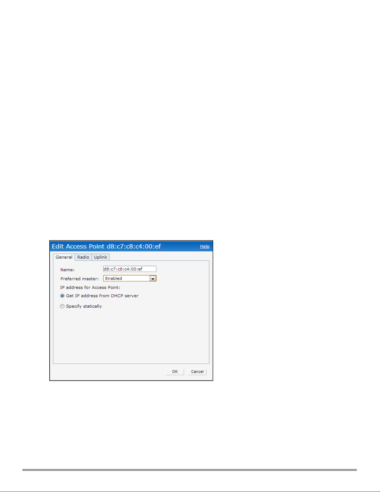
Preference to a W-IAP with Non-Default IP
The Master Election Protocol prefers a W-IAP with non-default IP, when electing a Virtual Controller for the Instant
network during initial startup. If there are more than one W-IAP with non-default IPs in the network, all W-IAPs with
default IP will automatically reboot and the DHCP process is used to assign new IP addresses.
Viewing Master Election Details
To verify the status of a W-IAP and master election details, use the following commands:
(Instant AP)# show election statistics
(Instant AP)# show summary support
Manual Provisioning of Master W-IAP
In most cases, the master election process automatically determines the best W-IAP that can perform the role of
Virtual Controller, which will apply its image and configuration to all other W-IAPs in the same AP management
VLAN. When the Virtual Controller goes down, a new Virtual Controller is elected.
Provisioning a W-IAP as a Master W-IAP
You can provision a W-IAP as a master W-IAP by using the Instant UI or CLI.
In the Instant UI
1. In the Access Points tab, click the W-IAP to modify. The edit link is displayed.
2. Click the edit link. The edit window for modifying W-IAP details is displayed.
3. Select Enabled from Preferred master drop-down. This option is disabled by default.
Figure 31 W-IAP Settings—Provisioning Master W-IAP
4. Click OK.
In the CLI
To provision a W-IAP as a master W-IAP:
(Instant AP)# iap-master
To verify if the W-IAP is provisioned as master IAP:
(Instant AP)# show ap-env
Antenna Type:Internal
Dell NetworkingW-Series Instant 6.4.0.2-4.1 | User Guide Customizing W-IAP Settings | 90
Page 91

Iap_master:1
Adding a W-IAP to the Network
To add a W-IAP to the Instant network, assign an IP address. For more information, see Assigning an IP address to
the W-IAP on page 35.
After a W-IAP is connected to the network, if the Auto Join Mode feature is enabled, the W-IAP inherits the
configuration from the Virtual Controller and is listed in the Access Points tab.
If the Auto Join Mode is disabled, perform the following steps to add a W-IAP to the network:
1. In the Access Points tab, click the New link. The New Access Point window is displayed.
2. In the New Access Point window, enter the MAC address for the new W-IAP.
3. Click OK.
Removing a W-IAP from the Network
You can remove a W-IAP from the network only if the Auto Join Mode feature is disabled. To remove a W-IAP from
the network:
1. In the Access Points tab, click the W-IAP to delete. The x icon is displayed against the W-IAP.
2. Click x to confirm the deletion.
The deleted W-IAPs cannot join the Instant network anymore and no longer are displayed in the Instant UI.
However, the master W-IAP details cannot be deleted from the Virtual Controller database.
91 | Customizing W-IAP Settings Dell Networking W-Series Instant 6.4.0.2-4.1 | User Guide
Page 92
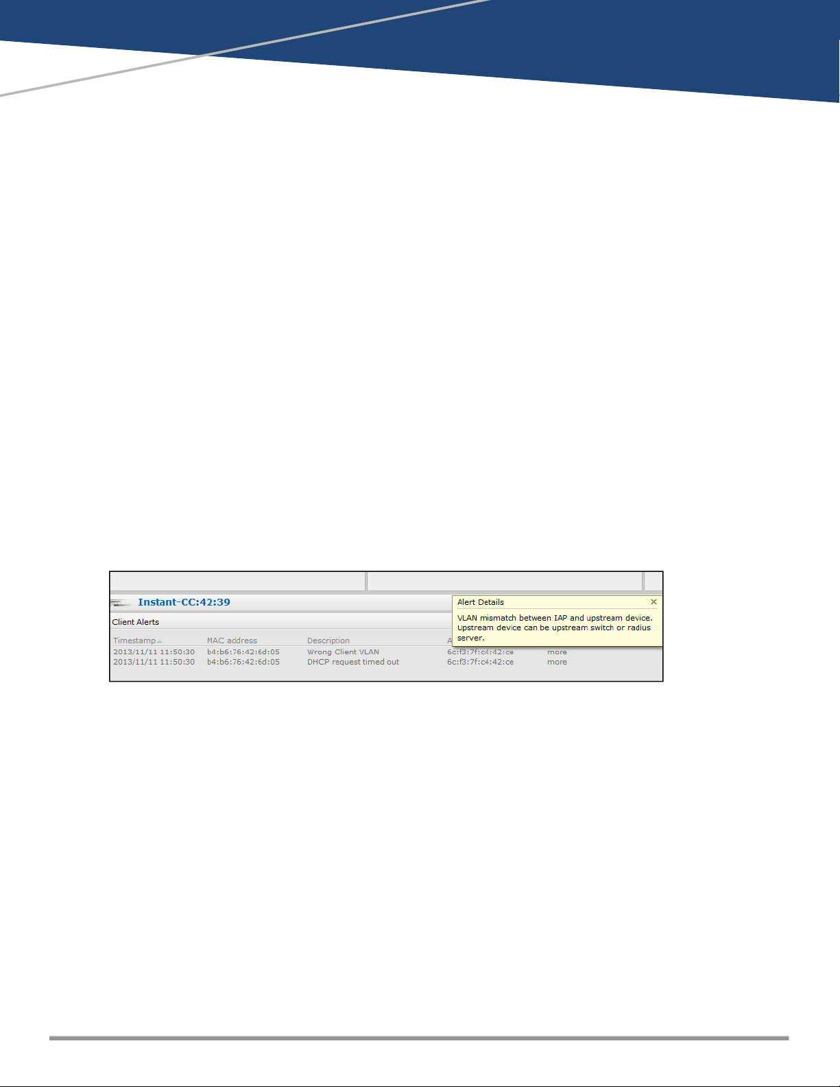
Chapter 7
VLAN Configuration
VLAN configuration is required for networks with more devices and broadcast traffic on a WLAN SSID or wired
profile. Based on the network type and its requirements, you can configure the VLANs for a WLAN SSID or wired
port profile.
For more information on VLANconfiguration for a WLANSSID and wired port profile, see Configuring VLAN Settings
for a WLAN SSID Profile on page 97 and Configuring VLAN for a Wired Profile on page 114.
VLAN Pooling
In a single W-IAP cluster, a large number of clients can be assigned to the same VLAN. Using the same VLAN for
multiple clients can lead to a high level of broadcasts in the same subnet. To manage the broadcast traffic, you can
partition the network into different subnets and use L3-mobility between those subnets when clients roam. However,
if a large number of clients need to be in the same subnet, you can configure VLAN pooling, in which each client is
randomly assigned a VLAN from a pool of VLANs on the same SSID. Thus, VLAN pooling allows automatic
partitioning of a single broadcast domain of clients into multiple VLANs.
Uplink VLAN Monitoring and Detection on Upstream Devices
If a client connects to an SSID or wired interface with a VLAN that is not allowed on the upstream device, the client
will not be assigned an IP address and thus cannot connect to the Internet. When a client connects to an SSID or a
wired interface with VLANthat is not allowed on the upstream device, the Instant UI now displays the following alert
message:
Figure 32 Uplink VLAN Detection
To resolve this issue, ensure that there is no mismatch in the VLAN configuration.
Dell NetworkingW-Series Instant 6.4.0.2-4.1 | User Guide VLAN Configuration | 92
Page 93

Chapter 8
Wireless Network Profiles
This chapter provides the following information:
l Configuring Wireless Network Profiles on page 93
l Configuring Fast Roaming for Wireless Clients on page 106
l Editing Status of a WLAN SSID Profile on page 110
l Editing a WLAN SSID Profile on page 110
l Deleting a WLAN SSID Profile on page 111
Configuring Wireless Network Profiles
During start up, a wireless client searches for radio signals or beacon frames that originate from the nearest W-IAP.
After locating the W-IAP, the following transactions take place between the client and the W-IAP:
1. Authentication — The W-IAP communicates with a RADIUS server to validate or authenticate the client.
2. Connection — After successful authentication, the client establishes a connection with the W-IAP.
Network Types
Instant wireless networks are categorized as:
l Employee network — An Employee network is a classic Wi-Fi network. This network type is used by the
employees in an organization and it supports passphrase-based or 802.1X based authentication methods.
Employees can access the protected data of an enterprise through the employee network after successful
authentication. The employee network is selected by default during a network profile configuration.
l Voice network —This Voice network type allows you to configure a network profile for devices that provide only
voice services such as handsets or applications that require voice traffic prioritization.
l Guest network —The Guest wireless network is created for guests, visitors, contractors, and any non-employee
users who use the enterprise Wi-Fi network. The Virtual Controller assigns the IP address for the guest clients.
captive portal or passphrase based authentication methods can be set for this wireless network. Typically, a
guest network is an un-encrypted network. However, you can specify the encryption settings when configuring a
guest network.
When a client is associated to the Voice network, all data traffic is marked and placed into the high priority queue in
QoS (Quality of Service).
To configure a new wireless network profile, complete the following procedures:
1. Configuring WLAN Settings
2. Configuring VLAN Settings
3. Configuring Security Settings
4. Configuring Access Rules for a Network
Configuring WLAN Settings for an SSID Profile
You can configure WLAN settings using the Instant UI or CLI.
Dell NetworkingW-Series Instant 6.4.0.2-4.1 | User Guide Wireless Network Profiles | 93
Page 94
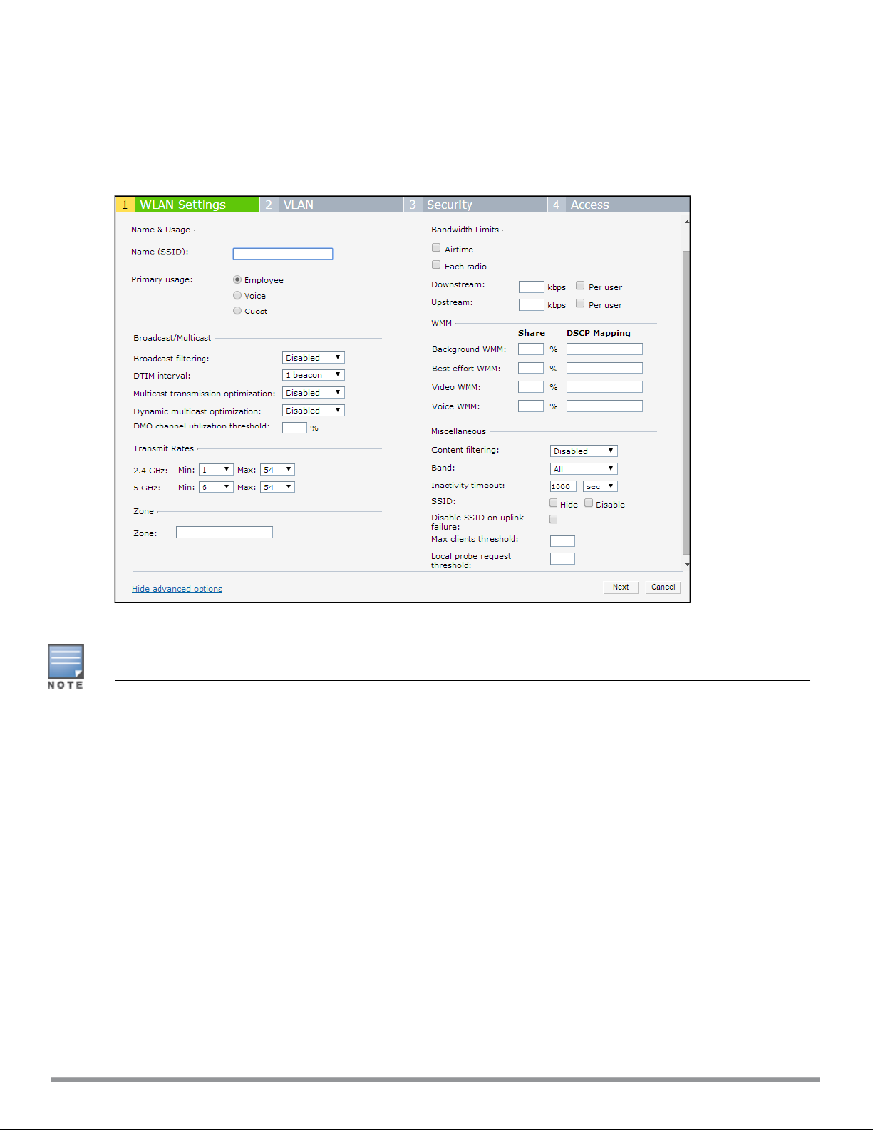
In the Instant UI
To configure WLAN settings:
1. In the Networks tab of the Instant main window, click the New link. The New WLAN window is displayed. The
following figure shows the contents of the WLAN Settings tab:
Figure 33 WLAN Settings Tab
2. Enter a name that uniquely identifies a wireless network in the Name (SSID) text box.
The SSIDName may contain any special character except for ' and ".
3. Based on the type of network profile, select any of the following options under Primary usage:
l Employee
l Voice
l Guest
4. Click the Show advanced options link. The advanced options for configuration are displayed. Specify the
following parameters as required.
94 | WirelessNetwork Profiles Dell Networking W-Series Instant 6.4.0.2-4.1 | User Guide
Page 95

Table 19:
WLAN Configuration Parameters
Parameter Description
Broadcast filtering
Select any of the following values:
l All—When set to All, the W-IAP drops all broadcast and multicast frames except DHCP
and ARP.
l ARP—When set to ARP, the W-IAP converts ARP requests to unicast and send frames
directly to the associated client.
l Disabled— When set to Disabled, all broadcast and multicast traffic is forwarded.
DTIM interval The DTIM interval indicates the delivery traffic indication message (DTIM) period in beacons,
which can be configured for every WLAN SSIDprofile. The DTIMinterval determines how
often the W-IAP should deliver the buffered broadcast and multicast frames to associated
clients in the powersave mode. The default value is 1, which means the client checks for
buffered data on the W-IAP at every beacon. You can also configure a higher DTIM value for
power saving.
Multicast transmission
optimization
Select Enabled if you want the W-IAP to select the optimal rate for sending broadcast and
multicast frames based on the lowest of unicast rates across all associated clients. When this
option is enabled, multicast traffic can be sent at up to 24 Mbps. The default rate for sending
frames for 2.4 GHz is 1 Mbps and 5.0 GHz is 6 Mbps. This option is disabled by default.
Dynamic multicast
optimization
Select Enabled to allow W-IAP to convert multicast streams into unicast streams over the
wireless link. Enabling Dynamic Multicast Optimization (DMO) enhances the quality and
reliability of streaming video, while preserving the bandwidth available to the non-video
clients.
NOTE: When you enable DMO on multicast SSID profiles, ensure that the DMO feature is
enabled on all SSIDs configured in the same VLAN.
DMO channel
utilization threshold
Specify a value to set a threshold for DMO channel utilization. With DMO, the W-IAP converts
multicast streams into unicast streams as long as the channel utilization does not exceed this
threshold. The default value is 90% and the maximum threshold value is 100%. When the
threshold is reached or exceeds the maximum value, the W-IAP sends multicast traffic over
the wireless link.
Transmit Rates
Zone
Bandwidth Limits
Specify the following parameters:
l 2.4 GHz—If the 2.4 GHz band is configured on the W-IAP, specify the minimum and
maximum transmission rate. The default value for minimum transmission rate is 1 Mbps
and maximum transmission rate is 54 Mbps.
l 5 GHz—If the 5 GHz band is configured on the W-IAP, specify the minimum and maximum
transmission rate. The default value for minimum transmission rate is 6 Mbps and
maximum transmission rate is 54 Mbps.
Specify the zone for the SSID. When the zone is defined in SSID profile and if the same zone
is defined on a W-IAP, the SSID is created on that W-IAP. For more information on
configuring zone details on an IAP, see Configuring Zone Settings on a W-IAP on page 84.
The following constraints apply to the zone configuration:
l A W-IAP can belong to only one zone and only one zone can be configured on an SSID.
l If an SSID belongs to a zone, all W-IAPs in this zone can broadcast this SSID. If no W-IAP
belongs to the zone configured on the SSID, the SSID is not broadcast.
l If an SSID does not belong to any zone, all W-IAPs can broadcast this SSID.
Under Bandwidth Limits:
l Airtime—Select this checkbox to specify an aggregate amount of airtime that all clients in
this network can use for sending and receiving data. Specify the airtime percentage.
l Each radio— Select this checkbox to specify an aggregate amount of throughput that each
radio is allowed to provide for the connected clients.
l Downstream and Upstream—Specify the downstream and upstream rates within a range
of 1 to 65535 Kbps for the SSID users. If the assignment is specific for each user, select
the Peruser checkbox.
Dell NetworkingW-Series Instant 6.4.0.2-4.1 | User Guide Wireless Network Profiles | 95
Page 96

Table 19:
WLAN Configuration Parameters
Parameter Description
Wi-Fi Multimedia
(WMM) traffic
management
Content filtering
Band
Inactivity timeout
Hide SSID
Disable SSID
Configure the following options for WMM traffic management. WMM supports voice, video,
best effort, and background access categories. To allocate bandwidth for the following types
of traffic, specify a percentage value under Share. To configure DSCP mapping, specify a
value under DSCP Mapping.
l Background W MM: For background traffic such as file downloads or print jobs.
l Best effort WMM — For best effort traffic such as traffic from legacy devices or traffic from
applications or devices that do not support QoS.
l Video WMM — For video traffic generated from video streaming.
l Voice WMM— For voice traffic generated from the incoming and outgoing voice
communication.
For more information on WMM traffic and DSCP mapping, see Wi-Fi Multimedia Traffic
Management on page 251
Select Enabled to route all DNS requests for the non-corporate domains to OpenDNS on this
network.
Select a value to specify the band at which the network transmits radio signals. You can set
the band to 2.4 GHz, 5 GHz, or All. The All option is selected by default.
Specify an interval for session timeout in seconds, minutes or hours. If a client session is
inactive for the specified duration, the session expires and the users are required to log in
again. You can specify a value within the range of 60-86400 seconds or up to 24 hours for a
client session. The default value is 1000 seconds.
Select this checkbox if you do not want the SSID (network name) to be visible to users.
Select this checkbox if you want to disable the SSID. On selecting this, the SSID will be
disabled, but will not be removed from the network. By default, all SSIDs are enabled.
Can be used without
Select the checkbox if you do not want to SSID profile to use uplink.
Uplink
Max clients threshold
Specify the maximum number of clients that can be configured for each BSSID on a WLAN.
You can specify a value within the range of 0 to 255. The default value is 64.
Local probe request
threshold
Specify a threshold value to limit the number of incoming probe requests. When a client
sends a broadcast probe request frame to search for all available SSIDs, this option controls
system response for this network profile and ignores probe requests if required. You can
specify a Received signal strength indication (RSSI) value within range of 0 to 100 dB.
5. Click Next to configure VLAN settings. For more information, see Configuring VLAN Settings for a WLAN SSID
Profile on page 97.
In the CLI
To configure WLAN settings for an SSID profile:
(Instant AP)(config)# wlan ssid-profile <name>
(Instant AP)(SSID Profile <name>)# essid <ESSID-name>
(Instant AP)(SSID Profile <name>)# type {<Employee>|<Voice>| <Guest>}
(Instant AP)(SSID Profile <name>)# broadcast-filter <type>
(Instant AP)(SSID Profile <name>)# dtim-period <number-of-beacons>
(Instant AP)(SSID Profile <name>)# multicast-rate-optimization
(Instant AP)(SSID Profile <name>)# dynamic-multicast-optimization
(Instant AP)(SSID Profile <name>)# dmo-channel-utilization-threshold
(Instant AP)(SSID Profile <name>)# a-max-tx-rate <rate>
(Instant AP)(SSID Profile <name>)# a-min-tx-rate <rate>
(Instant AP)(SSID Profile <name>)# g-max-tx-rate <rate>
(Instant AP)(SSID Profile <name>)# g-min-tx-rate <rate>
96 | WirelessNetwork Profiles Dell Networking W-Series Instant 6.4.0.2-4.1 | User Guide
Page 97
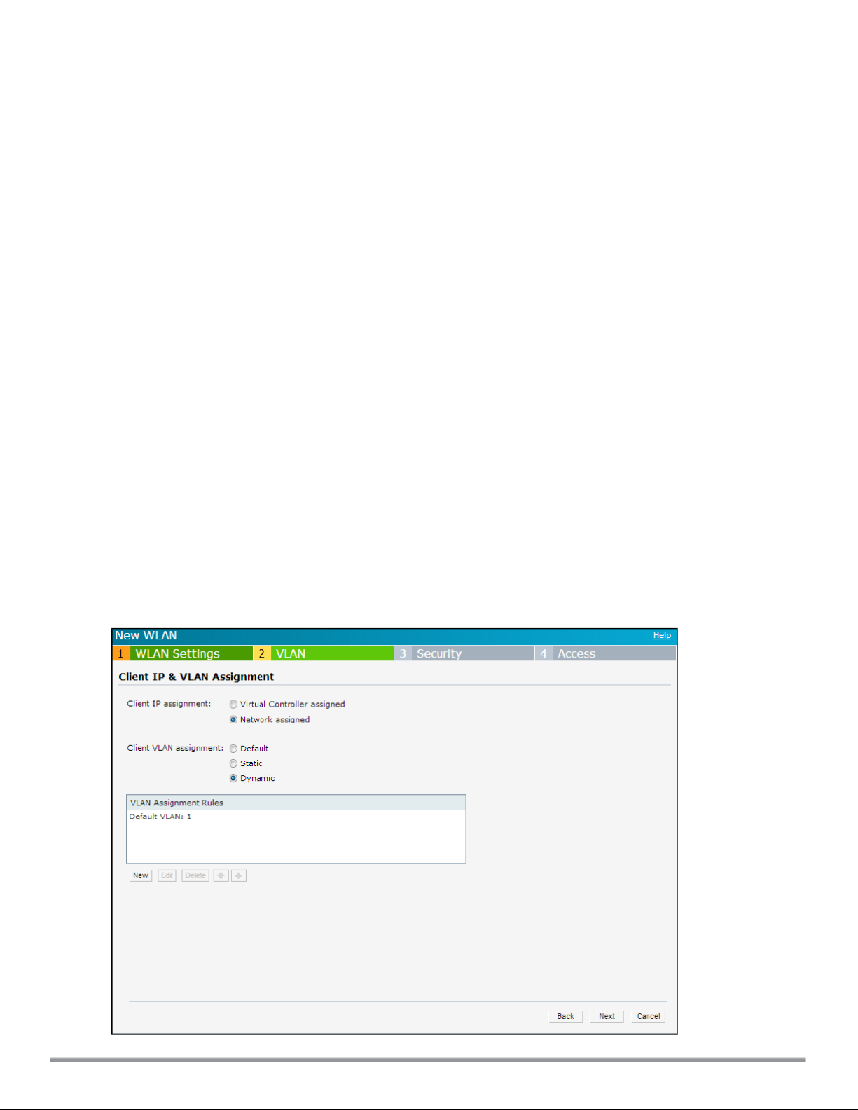
(Instant AP)(SSID Profile <name>)# zone <zone>
(Instant AP)(SSID Profile <name>)# bandwidth-limit <limit>
(Instant AP)(SSID Profile <name>)# per-user-bandwidth-limit <limit>
(Instant AP)(SSID Profile <name>)# air-time-limit <limit>
(Instant AP)(SSID Profile <name>)# wmm-background-dscp <dscp>
(Instant AP)(SSID Profile <name>)# wmm-background-share <share>
(Instant AP)(SSID Profile <name>)# wmm-best-effort-dscp <dscp>
(Instant AP)(SSID Profile <name>)# wmm-best-effort-share <share>
(Instant AP)(SSID Profile <name>)# wmm-video-dscp <dscp>
(Instant AP)(SSID Profile <name>)# wmm-video-share <share>
(Instant AP)(SSID Profile <name>)# wmm-voice-dscp <dscp>
(Instant AP)(SSID Profile <name>)# wmm-voice-share <share>
(Instant AP)(SSID Profile <name>)# rf-band {<2.4>|<5.0>|<all>}
(Instant AP)(SSID Profile <name>)# content-filtering
(Instant AP)(SSID Profile <name>)# hide-ssid
(Instant AP)(SSID Profile <name>)# inactivity-timeout <interval>
(Instant AP)(SSID Profile <name>)# work-without-uplink
(Instant AP)(SSID Profile <name>)# local-probe-req-thresh <threshold>
(Instant AP)(SSID Profile <name>)# max-clients-threshold <number-of-clients>
(Instant AP)(SSID Profile <name>)# end
(Instant AP)# commit apply
Configuring VLAN Settings for a WLAN SSID Profile
If you are creating a new SSID profile, complete the WLANSettings procedure before configuring VLAN. For more
information, see Configuring WLAN Settings for an SSID Profile on page 93.
You can configure VLAN settings for an SSID profile using the Instant UI or CLI.
In the Instant UI
To configure VLAN settings for an SSID:
1. In the VLAN tab of the New WLAN window. The VLAN tab contents are displayed.
Figure 34 VLAN Tab
Dell NetworkingW-Series Instant 6.4.0.2-4.1 | User Guide Wireless Network Profiles | 97
Page 98

2. Select any for the following options for Client IP assignment:
l Virtual Controller assigned—On selecting this option, the client obtains the IP address from the Virtual
Controller.
l Network assigned—On selecting this option, the IP address is obtained from the network.
3. Based on the type client IP assignment mode selected, you can configure the VLANassignment for clients as
described in the following table:
Table 20:
IP and VLAN Assignment for WLAN SSIDClients
Client IP Assignment Client VLAN Assignment
Virtual Controller assigned If the Virtual Cont roller assigned is selected for client IP assignment, the Virtual
Controller creates a private subnet and VLAN on the W-IAP for the wireless clients. The
network address translation for all client traffic that goes out of this interface is carried out
at the source. This setup eliminates the need for complex VLAN and IP address
management for a multi-site wireless network.
On selecting this option, the following client VLAN assignment options are displayed:
l Default: When selected, the default VLANas determined by the Virtual Controller is
assigned for clients.
l Custom: When selected, you can specify a custom VLAN assignment option. You can
select an existing DHCP scope for client IP and VLAN assignment or you can create
a new DHCP scope by selecting New. For more information on DHCP scopes, see
Configuring DHCP Scopes on page 201.
Network assigned
If the Network assigned is selected, you can specify any of the following options for the
Client VLAN assignment.
l Default— On selecting this option, the client obtains the IP address in the same
subnet as the W-IAPs. By default, the client VLAN is assigned to the native VLAN on
the wired network.
l Static— On selecting this option, you need to specify a single VLAN, a comma
separated list of VLANS, or a range of VLANs for all clients on this network. Select
this option for configuring VLAN pooling.
l Dynamic— On selecting this option, you can assign the VLANs dynamically from a
Dynamic Host Configuration Protocol (DHCP) server. To create VLAN assignment
rules, click New to assign the user to a VLAN. In the New VLAN Assignment Rule
window, enter the following information:
l Attribute— Select an attribute returned by the RADIUS server during
authentication.
l Operator— Select an operator for matching the string.
l String— Enter the string to match
l VLAN— Enter the VLAN to be assigned.
4. Click Next to configure security settings for the employee network. For more information, see Configuring
Security Settings for a WLAN SSID Profile on page 99.
In the CLI
To manually assign VLANs for WLAN SSID users:
(Instant AP)(config)# wlan ssid-profile <name>
(Instant AP)(SSID Profile <name>)# vlan <vlan-ID>
(Instant AP)(SSID Profile <name>)# end
(Instant AP)# commit apply
To enforce DHCP-based VLAN assignment:
(Instant AP)(config)# wlan ssid-profile <name>
(Instant AP)(SSID Profile <name>)# enforce-dhcp
(Instant AP)(SSID Profile <name>)# end
98 | WirelessNetwork Profiles Dell Networking W-Series Instant 6.4.0.2-4.1 | User Guide
Page 99
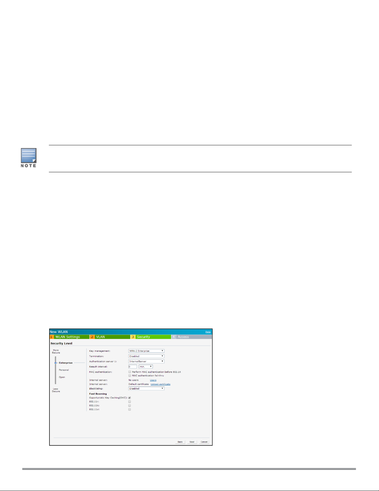
(Instant AP)# commit apply
To create a new VLAN assignment rule:
(Instant AP)(config)# wlan ssid-profile <name>
(Instant AP)(SSID Profile <name>)# set-vlan <attribute> {{contains|ends-with|equals|matchesregular-expression|not-equals|starts-with} <operand> <vlan>|value-of}
(Instant AP)(SSID Profile <name>)# end
(Instant AP)# commit apply
Configuring Security Settings for a WLAN SSID Profile
The following procedures are described in this section:
l Configuring Security Settings for an Employee or Voice Network on page 99
For information on guest network configuration, see Captive Portal for Guest Access.
If you are creating a new SSID profile, configure the WLANand VLAN settings before defining security settings.
For more information, see Configuring WLAN Settings for an SSID Profile on page 93 and Configuring VLAN
Settings for a WLAN SSID Profile on page 97.
Configuring Security Settings for an Employee or Voice Network
You can configure security settings for an employee or voice network by using the Instant UI or CLI.
In the Instant UI
To configure security settings for an employee or voice network:
1. In the Security tab, specify any of the following types of security levels by moving the slider to a desired level:
l Enterprise—On selecting enterprise security level, the authentication options applicable to the enterprise
network are displayed.
l Personal — On selecting personal security level, the authentication options applicable to the personalized
network are displayed.
l Open—On selecting Open security level, the authentication options applicable to an open network are
displayed:
The default security setting for a network profile is Personal.
The following figures show the configuration options for Enterprise, Personal, and Open security settings:
Figure 35 Security Tab: Enterprise
Dell NetworkingW-Series Instant 6.4.0.2-4.1 | User Guide Wireless Network Profiles | 99
Page 100
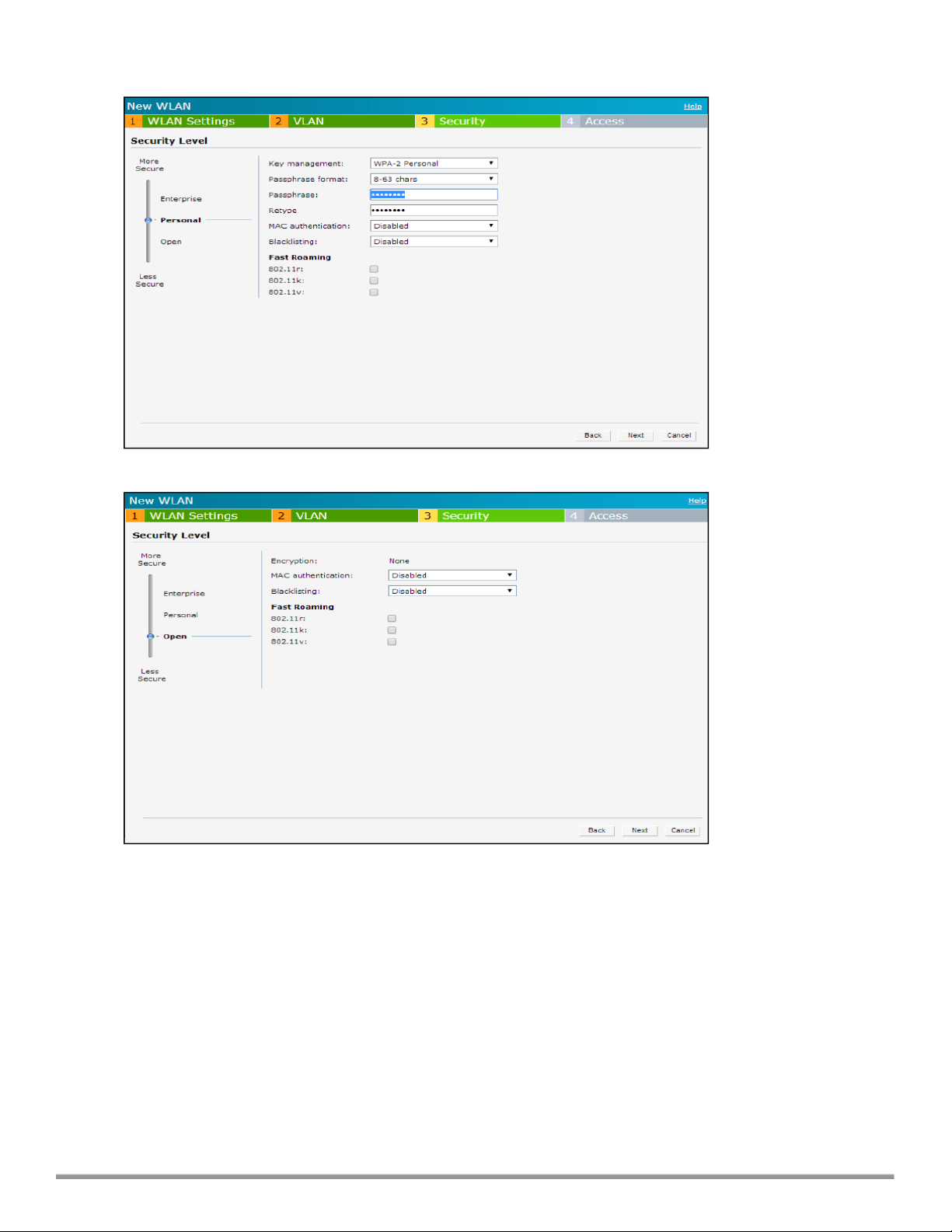
Figure 36 Security Tab: Personal
Figure 37 Security Tab: Open
2. Based on the security level specified, specify the following parameters:
100 | WirelessNetwork Profiles Dell Networking W-Series Instant 6.4.0.2-4.1 | User Guide
 Loading...