

Page 1

Dell EMC
VxBlock™ and Vblock® Systems 350
Administration Guide
Document revision 1.8
October 2017
Page 2

Revision history
Date Document revision Description of changes
October 2017 1.8 Added a section for configuring VMware
Enhanced Linked Mode (vSphere 6.5U1).
ELM dependencies and limitations - updated
statement regarding Vision software.
October 2017 1.7 Added and updated topics for VMware vSphere
6.5.
Updated the following topics:
Starting Cisco UCS Manager - added UCS
•
Manager 3.x changes.
Upgrading the Cisco UCS C2x0 Server -
•
split into two topics CIMC 2.x firmware and
CIMC 3.x.
Deleted the topic Backing up network devices
running Cisco IOS software - Nexus switches
do not run IOS so this topic was not required.
Refer to the topic Backing up network devices
running Cisco NX-OS software.
Adding a VLAN to a service profile template -
removed step 4.
September 2017 1.6 Added a section containing guidance for
configuring VMware Enhanced Linked Mode.
September 2017 1.5 Updated to support Dell EMC Unity All-Flash
350F, 450F, 550F, and 650F storage arrays for
VxBlock System 350.
August 2017 1.4 Made updates related to IPv6.
June 2017 1.3 Added the following section to the document:
Managing VMware NSX with VPLEX on
VxBlock Systems
February 2017 1.2 Added a note about how to determine whether
an NX-OS upgrade might need to be done in
two stages rather than the usual one.
Changes for Cisco Falcon software
Added support for IPv6.
December 2016 1.1 Removed VLAN 118 from topics.
October 2016 1.0 Initial version
Revision history | 2
Page 3

Contents
Introduction.................................................................................................................................................8
IPI Appliance............................................................................................................................................... 9
Managing compute resources.................................................................................................................10
Starting Cisco UCS Manager 3.x......................................................................................................... 10
Directly upgrading firmware at endpoints.......................................................................................10
Upgrading with Cisco UCS Firmware Auto Install..........................................................................12
Activating a Cisco UCS Manager Capability Catalog...........................................................................15
Activating a port license....................................................................................................................... 16
Adding a UUID range........................................................................................................................... 17
Deleting a UUID pool............................................................................................................................18
Adding a WWNN range........................................................................................................................ 18
Deleting a WWNN range...................................................................................................................... 19
Adding a WWPN range........................................................................................................................ 20
Deleting a WWPN range...................................................................................................................... 21
Adding a MAC address range.............................................................................................................. 22
Deleting a MAC pool............................................................................................................................ 23
Creating an IP address block in the management pool........................................................................23
Creating vNIC templates...................................................................................................................... 24
Modifying the time zone setting............................................................................................................25
Adding a network time protocol server...........................................................................................26
Removing a network time protocol server......................................................................................26
Adding a syslog server......................................................................................................................... 27
Removing a syslog server.................................................................................................................... 28
Adding an SNMP server.......................................................................................................................28
Removing an SNMP server..................................................................................................................29
Cisco Trusted Platform Module............................................................................................................ 29
Managing service profiles.....................................................................................................................30
Configuring service profile templates.............................................................................................30
Cloning the service profile templates.............................................................................................33
Adding vNICs to the service templates..........................................................................................34
Configuring service profile templates for Disjoint Layer 2..............................................................35
Assigning or modifying a management IPv4 address....................................................................36
Creating a named VLAN on both FIs.............................................................................................36
Creating an in-band network profile for the IPv6 management address assignment.................... 37
Assigning or modifying a management IPv6 address....................................................................38
Assigning service profiles.............................................................................................................. 38
Renaming service profiles..............................................................................................................39
Managing networking resources.............................................................................................................40
Managing VMware NSX....................................................................................................................... 40
Creating a named VLAN on both FIs................................................................................................... 40
Creating a new VLAN group.................................................................................................................41
Adding a VLAN to a service profile template........................................................................................41
Adding a VLAN to a vNIC template...................................................................................................... 42
3 | Contents
Page 4

Adding a VLAN to the Cisco Nexus 1000V Switch...............................................................................42
Adding a VLAN to the Cisco Nexus switches.......................................................................................43
Removing a VLAN from the Cisco Nexus switches..............................................................................43
Configuring a vPC................................................................................................................................ 44
Deleting a vPC..................................................................................................................................... 46
Adding VLANs to a vPC....................................................................................................................... 46
Removing VLANs from a vPC.............................................................................................................. 47
Adding vPCs to VLANs for Disjoint Layer 2 networks.......................................................................... 48
Viewing vPCs assigned to VLANs for Disjoint Layer 2 networks......................................................... 50
Removing vPCs from VLANs for Disjoint Layer 2 networks.................................................................50
Upgrading Cisco Nexus series switch software................................................................................... 51
Downgrading Cisco Nexus switch software......................................................................................... 53
Managing Cisco MDS switches............................................................................................................... 55
Upgrading Cisco MDS switch software................................................................................................ 55
Downgrading Cisco MDS switch software............................................................................................57
Configuring a VSAN............................................................................................................................. 57
Removing a VSAN............................................................................................................................... 58
Configuring a domain ID and priority for a VSAN.................................................................................58
Removing a domain ID and priority from a VSAN................................................................................ 59
Enabling FC interfaces......................................................................................................................... 60
Disabling FC interfaces........................................................................................................................ 60
Moving licenses between FC interfaces...............................................................................................61
Disabling port licenses......................................................................................................................... 62
Guidelines and configuration recommendations.................................................................................. 62
Zoning guidelines................................................................................................................................. 63
Managing storage resources...................................................................................................................64
Creating a storage pool........................................................................................................................ 64
Expanding a storage pool.....................................................................................................................64
Allocating block storage....................................................................................................................... 65
Managing NFS..................................................................................................................................... 66
Creating a NAS server...................................................................................................................66
Creating a file system.................................................................................................................... 67
Creating a tenant........................................................................................................................... 67
Creating NFS shares..................................................................................................................... 68
Managing VMware vSphere 6 with IPv6..................................................................................................69
Managing VMware vSphere ESXi 5.5 and 6.x.........................................................................................70
Installing the latest VMware vSphere ESXi patch (vSphere 6.0)......................................................... 70
Installing the latest VMware vSphere ESXi patch (vSphere 6.5)......................................................... 71
Configuring advanced settings for VMware vSphere ESXi (vSphere 6.0)........................................... 72
Configuring advanced settings for VMware vSphere ESXi (vSphere 6.5)........................................... 73
Restoring default values for VMware vSphere ESXi advanced settings (vSphere 6.0)....................... 74
Restoring default values for VMware vSphere ESXi advanced settings (vSphere 6.5)....................... 75
Hardening security on VMware vSphere ESXi hosts........................................................................... 75
Increasing the disk timeout on Microsoft Windows VMs...................................................................... 75
Installing vCenter Server root certificates on web browser (vSphere 6.5)........................................... 76
Contents | 4
Page 5

Setting up Java and Internet Explorer on the management workstation or VM (vSphere 6.x).............76
Managing VMware vCenter SSO for VMware vSphere 6.x....................................................................78
VMware vCenter SSO overview...........................................................................................................78
Unlocking and resetting the VMware vCenter SSO administrator password ...................................... 78
Managing the lockout status of VMware vCenter SSO account ..........................................................78
Managing VMware vCenter SSO default password policies................................................................ 79
Managing VMware vCenter SSO lockout policies................................................................................79
Adding an AD identity source to VMware vCenter SSO.......................................................................79
Backing up or restoring the VMware external PSC configuration........................................................ 81
File-Based Backing up and Restoring vCenter Server Appliance (vSphere 6.5)................................. 81
Redirecting VMware vCenter Server to the secondary external Platform Services Controller ............81
Managing virtualization............................................................................................................................83
Patching VMware vSphere ESXi hosts with the VUM (vSphere 6.0)................................................... 83
Patching VMware vSphere ESXi hosts with the VUM (vSphere 6.5)................................................... 85
Supported guest operating systems.....................................................................................................88
Using VMware Enhanced vMotion Compatibility with Cisco UCS blade servers................................. 88
Enabling VMware Enhanced vMotion Compatibility within a cluster.................................................... 89
Configuring the Virtual Flash Read Cache........................................................................................... 89
Managing VMware VDS............................................................................................................................ 91
Provisioning a VMware VDS configuration...........................................................................................91
Modifying an existing distributed port group.................................................................................. 91
Creating a distributed port group................................................................................................... 93
Configuring a VMkernel interface...................................................................................................93
Associating VMware vSphere ESXi hosts to an existing VMware VDS.........................................95
Configuring jumbo frames on VMware VDS.................................................................................. 96
Configuring jumbo frames on distributed port groups.................................................................... 97
Modifying CoS settings.................................................................................................................. 97
Decommissioning VMware VDS components......................................................................................98
Deleting a distributed port group....................................................................................................99
Disassociating the VMware vSphere ESXi host.......................................................................... 101
Removing a VMware VDS........................................................................................................... 105
Using disjoint layer 2 configuration on VMware VDS......................................................................... 108
Creating a VMware VDS for Disjoint Layer 2 configuration......................................................... 108
Creating distributed port groups for disjoint layer 2..................................................................... 109
Adding VMware vSphere ESXi hosts to VMware VDS................................................................ 110
Backing up and restoring a VMware VDS data configuration............................................................. 111
Exporting a backup of a VMware dvSwitch configuration............................................................ 111
Importing a backup of a dvSwitch configuration...........................................................................112
Restoring a backup of the dvSwitch configuration....................................................................... 113
VMware VDS basic troubleshooting................................................................................................... 113
Managing the Cisco Nexus 1000V Series Switch.................................................................................115
Managing licenses..............................................................................................................................115
Adding hosts.......................................................................................................................................115
Creating a port profile......................................................................................................................... 115
Modifying the uplink port profiles........................................................................................................ 116
5 | Contents
Page 6

Removing the uplink port profiles....................................................................................................... 118
Modifying vEthernet data port profiles................................................................................................ 118
Modifying the QoS settings ............................................................................................................... 120
Upgrading the VEM software............................................................................................................. 121
Troubleshooting the Cisco Nexus 1000V switch................................................................................ 121
Managing VMware NSX with VPLEX on VxBlock Systems.................................................................123
Performing a graceful failover............................................................................................................ 123
Performing a graceful recovery.......................................................................................................... 127
Managing AMP-2.....................................................................................................................................131
Upgrading the Cisco UCS C2x0 Server (CIMC 2.x firmware)............................................................ 131
Upgrading the Cisco UCS C2x0 Server (CIMC 3.x firmware)............................................................ 132
Upgrading VNXe3200 Software......................................................................................................... 133
Creating a new VMware datastore..................................................................................................... 133
Changing the VMware datastore capacity .........................................................................................134
Adding a VMware ESXi host for IPv4.................................................................................................135
Adding a VMware vSphere ESXi host for IPv6.................................................................................. 136
Adding datastore access to a VMware ESXi Host............................................................................. 136
Configuring VMware ESXi persistent scratch location ...................................................................... 137
Configuring RAID devices for AMP-2................................................................................................. 138
Disabling VAAI primitives for AMP-2.................................................................................................. 139
Backing up AMP-2..............................................................................................................................139
Creating an instance of the configuration repository....................................................................139
Creating a backup of a configuration repository.......................................................................... 140
Restoring a configuration file....................................................................................................... 141
Backing up targets in the Converged System..............................................................................141
Guidelines for backing up configuration files......................................................................................143
Backing up configuration files.............................................................................................................143
Backing up network devices running Cisco NX-OS software.............................................................143
Backing up Cisco UCS FIs................................................................................................................. 145
Creating and runnig the backup using the Cisco UCS Manager................................................. 146
By using the Cisco UCS CLI........................................................................................................147
Creating and running the backup using scheduled backups....................................................... 148
Configuring fault suppression...................................................................................................... 149
Backing up the VMware vCenter SQL server database.....................................................................149
Backing up Cisco MDS switches...........................................................................................................154
Creating backups of startup and running configuration files.............................................................. 154
Creating a script to purge older copies of the backup files.................................................................154
Scheduling the task to purge older backup files.................................................................................155
Configuring VMware Enhanced Linked Mode (vSphere 6.0).............................................................. 157
Introduction.........................................................................................................................................157
VMware vSphere 6.0 ELM use cases................................................................................................ 157
Backing up and restoring Converged Systems with ELM.................................................................. 158
Converged System AMP design........................................................................................................ 159
ELM scalability planning.....................................................................................................................160
Intra Converged System ELM scalability planning.......................................................................161
Contents | 6
Page 7

Inter Converged System ELM scalability planning in a single physical data center.................... 162
Inter Converged System ELM scalability planning with multiple physical data centers............... 163
ELM deployment information..............................................................................................................163
ELM dependencies and limitations.....................................................................................................165
VMware ELM References.................................................................................................................. 166
Conclusions........................................................................................................................................166
Configuring VMware Enhanced Linked Mode (vSphere 6.5U1)..........................................................168
Introduction to ELM (vSphere 6.5U1).................................................................................................168
VMware ELM with VMware vSphere 6.5U1 use cases...................................................................... 168
Backup and restore Converged Systems with VMware ELM (vSphere 6.5)...................................... 169
Backing up the PSC using the backup option..............................................................................169
Restoring a failed PSC.................................................................................................................169
Backup and recovery capabilities................................................................................................ 170
Converged System AMP design (ELM/vSphere 6.5U1).....................................................................171
VMware ELM scalability planning (vSphere 6.5U1)........................................................................... 174
Intra Converged System VMware ELM scalability planning (vSphere 6.5U1)............................. 175
Inter Converged System VMware ELM scalability planning in Converged Systems in a single
physical data center (vSphere 6.5U1)..........................................................................................176
Inter Converged System ELM scalability planning with multiple physical data centers
(vSphere 6.5U1)...........................................................................................................................177
WMware ELM deployment information (vSphere 6.5U1)................................................................... 177
VMware ELM references (vSphere 6.5U1)........................................................................................ 179
VMware ELM conclusions (vSphere 6.5U1).......................................................................................179
7 | Contents
Page 8

Introduction
This guide contains instructions for managing the Converged Systems after installation at the customer
site.
In this document, the Vblock System and the VxBlock System are referred to as the Converged System.
The target audience for this document includes those responsible for managing the Converged System,
including the system administrator and Dell EMC personnel responsible for remote management. The
document assumes that the administrator:
Is familiar with VMware, Dell EMC storage technologies, and Cisco compute and networking
•
technologies
Is familiar with Converged System concepts and terminology
•
Has Converged System troubleshooting skills
•
Refer to the Glossary for definitions of terms specific to Dell EMC.
Introduction | 8
Page 9

IPI Appliance
The IPI Appliance provides an intelligent gateway to gather information about power, thermals, security,
alerts, and all components in the physical infrastructure of each cabinet.
Vision Intelligent Operations uses SNMP to poll the status of the IPI Appliance and then passes the
results to VMware vCenter.
For cabinet-related operations such as adding users or cabinet access cards, refer to the VCE Intelligent
Physical Infrastructure Appliance User Manual.
Refer to the management release certification matrix (RCM) to identify the recommended firmware
version for your IPI Appliance. Contact Support with any questions.
Accessing the IPI Appliance
To access the IPI Appliance in a given cabinet, connect a laptop to the appropriate subnet and use a
browser to access the IPI Appliance.
The following default settings apply:
IP address: 192.168.0.253
•
Mask: 255.255.255.0
•
Gateway: 192.168.0.1
•
9 | IPI Appliance
Page 10

Managing compute resources
Starting Cisco UCS Manager 3.x
Cisco UCS Manager, Version 3.1.1 provides an HTML5 based web interface that can be used in place of
the traditional Java-based Cisco UCSM applet.
About this task
These instructions apply for Java-based interfaces on all current versions of the Cisco UCS Manager.
Settings, policies, and pools apply regardless of the interface used.
Before you begin
For more information on using the HTML5 web interface, refer to the Cisco UCS Manager GUI
Configuration Guide for versions 3.1.1 and higher.
Procedure
1 From a web browser, open the web link for Cisco UCS Manager GUI at: http(s)://
UCSManager_IP.
2 Type the virtual cluster IP address of the management port on the fabric interconnect.
3 If a Security Alert dialog box appears, click Yes to accept the security certificate and continue.
4 In the Cisco UCS Manager window, click Launch UCS Manager.
5 For Cisco UCS Manager versions 3.1.1 and higher, click Launch UCS Manager to launch the
HTML page.
6 If a banner window appears, review the message and click OK.
7 If a Security dialog box appears, check the box to accept all content from Cisco, and click Yes.
8 In the Login dialog box, type your username and password.
9 If your Cisco UCS implementation includes multiple domains, select the appropriate domain from
the Domain drop-down list, then click Login.
What to do next
Directly upgrading firmware at endpoints
Directly upgrading firmware at endpoints
Some components in the Converged Systems may require a reboot after being updated. Upgrading Cisco
UCS software impacts the Cisco UCS Manager, fabric interconnects, I/O modules, chassis, chassis
blades, and mezzanine adapters.
Managing compute resources | 10
Page 11

Before you begin
Coordinate firmware upgrades during maintenance windows and refer to Cisco documentation for
•
proper upgrade procedures.
Download the latest Cisco UCS B-Series GUI Firmware Management Guide.
•
Run a full state and all configuration backup.
•
For a cluster configuration, verify the high availability status of both fabric interconnect shows up
•
and running.
Verify all servers, I/O modules, and adapters are fully functional. An inoperable server cannot be
•
upgraded.
Verify all servers have been discovered. Servers do not need to be powered on or associated
•
with a service profile.
Verify the time, date, and time zone of fabric interconnects are identical for a cluster using a
•
central time source such as NTP.
Best practices for managing firmware in the Cisco UCS Manager are documented by Cisco. Ensure that
the firmware versions are compatible with the Release Certification Matrix.
Procedure
1 Perform the Cisco UCS upgrade as described in the Cisco UCS B-Series GUI Firmware
Management Guide for the release being installed.
2 To verify the upgrade, from the Navigation window, select the Equipment tab and select the
Equipment node.
3 From the Work window, select the Firmware Management tab.
4 From the Installed Firmware tab, click Update Firmware. Cisco UCS Manager GUI opens the
Update Firmware dialog box and verifies the firmware versions for all endpoints in the Cisco UCS
domain. This step take a few minutes, based on the number of chassis and servers.
5 From the Update Firmware dialog, perform the following:
a From the Filter drop-down menu, select ALL.
b Select the endpoint firmware to update and click OK.
What to do next
Verify the following:
All components are running the correct version of firmware.
•
No new Cisco UCS faults were introduced because of the upgrade.
•
All hosts have booted successfully.
•
11 | Managing compute resources
Page 12

Related information
Cisco UCS Manager GUI Configuration Guide
Cisco UCS B-Series GUI Firmware Management Guide
Upgrading Cisco UCS software with Cisco UCS Firmware Auto Install
Upgrade Cisco UCS software using Cisco UCS Firmware Auto Install on Cisco UCS B-Series chassis and
blade servers.
About this task
The Cisco UCS Firmware Auto Install feature is performed in two stages that include upgrading the Cisco
UCS infrastructure and server firmware.
Upgrading the Cisco UCS infrastructure firmware includes:
Fabric interconnect kernel and system
•
I/O module
•
Cisco UCS Manager
•
Upgrading the Cisco UCS server firmware includes:
Adapter
•
BIOS
•
CIMC
•
RAID controller
•
Disk firmware
•
These stages can be manually run or scheduled to run at different times, but never simultaneously. Cisco
UCS infrastructure firmware upgrades must be updated first. Different versions of Cisco UCS
infrastructure firmware and Cisco UCS server firmware are not supported. Cisco UCS infrastructure
firmware upgrades do not support a partial upgrade to some infrastructure components in a Cisco UCS
domain. Cisco UCSM does not support managing firmware on fusion I/O or LSI flash cards.
The Cisco UCS firmware auto install feature has the following scheduling options:
Upgrade stage Scheduling options
Infrastructure firmware
Configure an immediate upgrade or specify a start time.
•
If a start time is not specified, the upgrade begins when the transaction is committed.
•
You can not cancel a Cisco UCS infrastructure firmware upgrade after it has begun
•
but can cancel upgrades scheduled to occur in the future.
Cisco UCS infrastructure firmware upgrades require an acknowledgement for an
•
administrator user before the primary fabric interconnect is rebooted. The subordinate
fabric interconnect reboots automatically.
Managing compute resources | 12
Page 13

Upgrade stage Scheduling options
Server firmware
The Cisco UCS Manager, fabric interconnects, I/O modules, chassis, chassis blades, and mezzanine
adapters are impacted by the upgrade of Cisco UCS software.
Before you begin
The Dell EMC Host Firmware Policy must be used for Cisco UCS server firmware
•
upgrades and can be configured for an immediate or scheduled upgrade.
The server reboot is based on the maintenance policy that has been configured for
•
each service profile. The default is for an immediate server reboot.
Create and deploy a maintenance policy called VCE_UserAck with the user
•
acknowledgment option selected. This option requires an administrator level user
to acknowledge the reboot request for each server.
You cannot cancel Cisco UCS server firmware upgrades after you complete the
•
configuration in the Cisco UCS Install Server Firmware wizard.
A change in the firmware version is required every time you perform the Cisco UCS
•
firmware auto install.
The Cisco UCS server firmware auto install feature can only be executed once per
•
firmware version.
You cannot run the Cisco UCS server firmware auto install feature when new servers
•
are added. Update servers by creating and associating new service profiles with the
correct host firmware package.
Reboot as needed when updating Converged System components. Coordinate firmware upgrades during
maintenance windows and refer to Cisco documentation for proper upgrade procedures.
Download the latest Cisco UCS B-Series GUI Firmware Management Guide.
•
Back up the configuration file into an all configuration backup file and perform a full state backup.
•
The time, date, and time zone of the fabric interconnects must be identical for a cluster using a
•
centralized time source such as NTP.
Verify the following:
•
—
Both fabric interconnects are up and running for a cluster configuration.
—
All servers, I/O modules, and adapters are fully functional. An inoperable server cannot be
upgraded.
—
All servers are discovered. The servers do not need to be powered on or associated with a
service profile.
—
The software version for the UCS firmware auto install feature is 2.1(1) or later.
—
All endpoints are at Cisco UCS release 1.4 or later to run the Cisco UCS auto install.
—
All endpoints are running the latest firmware release or patch for that release.
For the Cisco UCS Server Firmware Auto Install Feature, perform the following prerequisites:
•
—
Remove management firmware packages from all service profile templates and service
profiles.
13 | Managing compute resources
Page 14

—
Configure and deploy the VCE_UserAck maintenance policy in all new and existing
associated service profiles. Complete this before configuring host firmware policies to support
the Cisco UCS server firmware auto install feature.
Create a new host firmware policy for the version of code being deployed. During creation of the
•
policy, do not set the package version or define specific firmware versions. The Cisco UCS
Server Firmware Auto Install wizard updates the embedded firmware package version of the
policy. Assign this new host firmware policy to the service profiles or service profile templates
associated with the blade in which you wish to update using Auto Install. If the service profile
does not set the host firmware policy for the blade, the host firmware policy is set to the default.
Do not update the Cisco UCS default host firmware package with server firmware upgrades or
•
reference the package with the server Cisco UCS Auto Install wizard. This may result in
unexpected server reboots. If the default host firmware policy is used in the service profile and
the default host firmware policy is updated, the blade could reboot if the default maintenance
policy (immediate reboot) is configured. Updating the default host firmware package for a new
firmware version can trigger an update and immediate reboot of all unassociated servers.
Setting a firmware package version during the initial creation of the host firmware policy could trigger an
immediate upgrade of the blade. Depending on the maintenance policy for the service profile, an
unexpected server reboot could occur. Cisco has documented best practices for managing firmware in
the Cisco UCS Manager. Ensure that the firmware versions are compatible with the RCM.
To perform a Cisco UCS upgrade, refer to the Cisco UCS B-Series GUI Firmware Management Guide for
the specific release being installed.
Procedure
1 To upgrade the Cisco UCS Infrastructure Firmware, perform the following:
a Select the Equipment tab and then select the Firmware Management tab.
b From the Firmware Management tab, select the Firmware Auto Install tab.
c Select Install Infrastructure Firmware Upgrade.
d On the Prerequisites page, do not check any boxes.
Important: If no system backup was performed, critical and/or major faults exist, or the
Management Interfaces Monitoring Policy has not been configured or enabled, do
not continue with the upgrade. Do not bypass any of the checks.
Scheduled upgrades are the recommended methodology for Infrastructure
upgrades. The secondary fabric interconnect is upgraded automatically, but the
primary fabric interconnect is not upgraded without a user acknowledgement.
e Click Finish.
2 To upgrade Cisco UCS Server Firmware, perform the following:
a Select the Equipment tab on the left, and then select the Firmware Management tab on the
right.
b From the Firmware Management tab, select the Firmware Auto Install tab.
c Select Install Server Firmware. Server upgrades occur after pending acknowledgements for
server reboots are acknowledged.
Managing compute resources | 14
Page 15

d On the Prerequisites page, do not check any boxes.
Important: If no system backup was performed, critical and/or major faults exist, or the
Management Interfaces Monitoring Policy has not been configured or enabled, do
not continue with the upgrade. Do not bypass any of the checks.
e On the Select Package Versions page, select the firmware version for the Cisco B-Series
Blade software field and click Next.
f On the Select Host Firmware Packages page, select the VCE-HostFirmware package you
created and click Next.
g On the Host Firmware Package Dependencies page, click Next.
h On the Impacted Endpoints Summary page, click Install.
i When appropriate, assign the new host firmware package to the blade servers that require
the code upgrade. This requires a server reboot.
What to do next
If required, follow the Cisco recommended procedures for firmware downgrades. If you downgrade a
Cisco UCS domain to a previous release, remove all unsupported features from the current release.
Related information
Cisco UCS Manager GUI Configuration Guide
Cisco UCS B-Series GUI Firmware Management Guide
Activating a Cisco UCS Manager Capability Catalog
The Cisco UCS Manager Capability Catalog is a set of tunable parameters, strings, and rules used by the
Cisco UCS Manager to update the display and configure components.
About this task
The catalog is divided by hardware components, such as the chassis, CPU, local disks, and the I/O
module. There is one provider per hardware component. Use the catalog to view the list of providers
available for that component. Each provider is identified by the vendor, model (PID), and revision. For
each provider, you can view details of the equipment manufacturer and the form factor.
Cisco UCS Manager Capability Catalog updates are included in each Cisco UCS Manager update.
Unless otherwise instructed by Cisco Technical Support, only activate the Capability Catalog update after
you have downloaded, updated, and activated a Cisco UCS infrastructure software bundle.
When you activate a Capability Catalog update, the Cisco UCS Manager immediately updates to the new
baseline catalog. You do not need to perform any further tasks or reboot any component in the Cisco
UCS instance or reinstall the Cisco UCS Manager when you perform an update.
Each Cisco UCS Manager release contains a baseline catalog. In rare cases, Cisco releases an update
to the Capability Catalog and makes it available on the same site where you download firmware images.
15 | Managing compute resources
Page 16

Before you begin
Download, update, and activate a Cisco UCS infrastructure software bundle before activating a capability
catalog.
Procedure
Refer to the appropriate Cisco UCS B-Series GUI Firmware Management Guide for your release to
update the Cisco UCS Manager Capability Catalog.
Related information
Cisco UCS Manager GUI Configuration Guide
Cisco UCS B-Series GUI Firmware Management Guide
Activating a port license
Port licenses for each Cisco UCS fabric interconnect are factory installed and shipped with the hardware.
Activate a port license using the Cisco UCS Manager.
About this task
Expansion modules come with eight licenses that can be used on the expansion module or the base
module. The eight default licenses that come with the Cisco UCS 6248UP Fabric Interconnect expansion
module can be used to enable ports on the base module, but travel with the expansion module if it is
removed. If the expansion module is removed, any default expansion module licenses used by the base
module are removed from the ports on the base module. This results in unlicensed ports.
Port licenses are not bound to physical ports. When a licensed port is disabled, the license is retained for
use with the next enabled port. Install licenses to use additional fixed ports. If you use an unlicensed port,
the Cisco UCSM initiates a 120-day grace period measured from the first use of the unlicensed port and
is paused when a valid license file is installed. The amount of time used in the grace period is retained by
the system. Each physical port has its own grace period. Initiating the grace period on a single port does
not initiate the grace period for all ports.
If a licensed port is not configured, that license is transferred to a port functioning within a grace period. If
multiple ports are acting within grace periods, the license is moved to the port whose grace period is
closest to expiring.
To avoid inconsistencies during failover, fabric interconnects in the cluster should have the same number
of licensed ports. If symmetry is not maintained and failover occurs, Cisco UCS enables the missing
licenses and initiates the grace period for each port used on the failover node.
Converged Systems ship with the appropriate number of fabric interconnect licenses installed. If
additional licenses are needed, request a chassis activation kit.
Procedure
To view, obtain, download, install, and uninstall a fabric interconnect license, refer to the Cisco UCS
Manager GUI Configuration Guide for your release.
Managing compute resources | 16
Page 17

Related information
Cisco UCS Manager GUI Configuration Guide
Adding a UUID range
Add a range to a UUID pool using the Cisco UCS Manager.
Before you begin
Verify the new UUID range does not exist on any pre-existing Cisco UCS compute environment.
Procedure
1 Log on to the Cisco UCS Manager.
2 In the Navigation window, select the Servers tab.
3 On the Servers tab, expand Servers > Pools.
4 Expand the node for the organization where you want to create the pool. If the system does not
include multi-tenancy, expand the root node.
5 Right-click UUID Suffix Pools and select Create UUID Suffix Pool.
6 In the Define Name and Description window of the Create UUID Suffix Pool wizard, perform
the following:
a In the Name field, type the name of the UUID pool.
b In the Description field, type a description of the pool.
c In the Prefix field, either select Derived (the system creates the suffix) or Other (allows you
to specify the suffix).
7 In the Add UUID Blocks window of the Create UUID Suffix Pool wizard, click Add.
8 From the Create a Block of UUID Suffixes window:
a Type the first UUID suffix in the pool and the number of UUID suffixes to include in the pool.
b Click OK.
9 Click Finish.
What to do next
Include the UUID suffix pool in a service profile and/or template.
Related information
Deleting a UUID pool (see page 18)
17 | Managing compute resources
Page 18

Cisco UCS Manager GUI Configuration Guide
Deleting a UUID pool
Delete a UUID pool using the Cisco UCS Manager. If you delete a pool, the addresses are not reallocated
from the pool that have been assigned to vNICs or vHBAs.
About this task
All assigned addresses from a deleted pool remain with the vNIC or vHBA to which they are assigned
until:
Associated service profiles are deleted.
•
The vNIC or vHBA to which the address is assigned is deleted or assigned to a different pool.
•
Procedure
1 Log on to the Cisco UCS Manager.
2 In the Navigation window, select the Servers tab.
3 On the Servers tab, expand Servers > Pools > Organization_Name.
4 Expand the UUID Suffix Pools node.
5 Right-click the pool and select Delete.
6 If a confirmation dialog box appears, click Yes.
Related information
Adding a UUID range (see page 17)
Cisco UCS Manager GUI Configuration Guide
Adding a WWNN range
Add a range to the WWNN pool using the Cisco UCS Manager. A WWNN pool is a WWN pool that
contains only WW node names.
About this task
A WWN pool only includes WWNNs or WWPNs in the following ranges:
20:00:00:00:00:00:00:00 to 20:FF:FF:FF:FF:FF:FF:FF
•
50:00:00:00:00:00:00:00 to 5F:FF:FF:FF:FF:FF:FF:FF.
•
All other WWN ranges are reserved. To ensure the uniqueness of the Cisco UCS WWNNs and WWPNs
in the SAN fabric, use the WWN prefix 20:00:00:25:B5:XX:XX:XX for all blocks in a pool.
Managing compute resources | 18
Page 19

Before you begin
Obtain the WWNN information.
Procedure
1 Log on to the Cisco UCS Manager.
2 In the Navigation window, select the SAN tab.
3 In the SAN tab, expand SAN > Pools.
4 Expand the node for the organization where you want to create the pool. If the system does not
include multi-tenancy, expand the root node.
5 Right-click WWNN Pools and select Create WWNN Pool.
6 From the WWNN Pool window, perform the following:
a In the Define Name and Description window, type a unique name and description for the
WWNN pool.
b Next.
7 In the Add WWN Blocks window, click Add.
8 In the Create WWN Block window, perform the following:
a In the From field, type the first WWNN in the pool.
b In the Size field, type the number of WWNNs to include in the pool.
c Click OK.
9 Click Finish.
What to do next
Include the WWNN pool in a vHBA template.
Related information
Deleting a WWNN range (see page 19)
Cisco UCS Manager GUI Configuration Guide
Deleting a WWNN range
Delete a range from the WWNN pool using the Cisco UCS Manager. If you delete a pool, the addresses
are not reallocated from the pool that have been assigned to vNICs or vHBAs.
19 | Managing compute resources
Page 20

About this task
All assigned addresses from a deleted pool remain with the vNIC or vHBA to which they are assigned
until:
Associated service profiles are deleted.
•
The vNIC or vHBA to which the address is assigned is deleted or assigned to a different pool.
•
Procedure
1 Log on to the Cisco UCS Manager.
2 In the Navigation window, select the SAN tab.
3 In the SAN tab, expand SAN > Pools > Organization_Name.
4 Expand the WWNN Pools node.
5 Right-click the WWNN pool you want to delete and select Delete.
6 If a confirmation dialog box appears, click Yes.
Related information
Adding a WWNN range (see page 18)
Cisco UCS Manager GUI Configuration Guide
Adding a WWPN range
Add a range to the WWPN pool using the Cisco UCS Manager.
About this task
A WWN pool only includes WWNNs or WWPNs in the following ranges:
20:00:00:00:00:00:00:00 to 20:FF:FF:FF:FF:FF:FF:FF
•
50:00:00:00:00:00:00:00 to 5F:FF:FF:FF:FF:FF:FF:FF
•
All other WWN ranges are reserved. To ensure the uniqueness of the Cisco UCS WWNNs and WWPNs
in the SAN fabric use the following WWN prefix for all blocks in a pool: 20:00:00:25:B5:XX:XX:XX
Create separate WWPN pools for SAN Fabric A and SAN Fabric B.
Before you begin
Obtain the WWPN information.
Procedure
1 Log on to the Cisco UCS Manager.
2 In the Navigation window, select the SAN tab.
Managing compute resources | 20
Page 21

3 Expand SAN > Pools.
4 Expand the node for the organization where you want to create the pool. If the system does not
include multi-tenancy, expand the root node.
5 Right-click WWPN Pools and select Create WWNN Pool.
6 From the WWNN Pool window, perform the following:
a In the Define Name and Description window, type a unique name and description for the
WWNN pool.
b Next.
7 In the Add WWN Blocks window, click Add.
8 In the Create WWN Block window, perform the following:
a In the From field, type the first WWPN in the pool.
b In the Size field, type the number of WWPNs to include in the pool.
c Click OK.
9 Click Finish.
What to do next
Include the WWPN pool in a vHBA template.
Related information
Cisco UCS Manager GUI Configuration Guide
Deleting a WWPN range
Delete a WWPN range from the WWPN pool using the Cisco UCS Manager. If you delete a pool, the
addresses are not reallocated from the pool that have been assigned to vNICs or vHBAs.
About this task
All assigned addresses from a deleted pool remain with the vNIC or vHBA to which they are assigned
until:
Associated service profiles are deleted.
•
The vNIC or vHBA to which the address is assigned is deleted or assigned to a different pool.
•
Procedure
1 Log on to the Cisco UCS Manager.
2 In the Navigation window, select the SAN tab.
21 | Managing compute resources
Page 22

3 In the SAN tab, expand SAN > Pools > Organization_Name > WWPN Pools >
WWPN_Pool_Name.
4 Expand the WWPN Pools node.
5 Right-click the WWPN pool you want to delete and select Delete.
6 If a confirmation dialog box appears, click Yes.
Adding a MAC address range
Add a range to the MAC address pool using the Cisco UCS Manager.
Procedure
1 Log on to the Cisco UCS Manager.
2 In the Navigation window, select the LAN tab.
3 Expand LAN > Pools.
4 Expand the node for the organization where you want to create the pool. If the system does not
include multi-tenancy, expand the root node.
5 Right-click MAC Pools and select Create MAC Pool.
6 In the first window of the Create MAC Pool wizard, perform the following:
a In the Define Name and Description window, type a unique name and description for the
MAC pool.
b Next.
7 In the Add MAC Addresses window, click Add.
8 In the Create a Block of MAC Addresses window, type the first MAC address in the pool and
the number of MAC addresses to include in the pool.
9 Click Finish.
What to do next
Include the MAC pool in a vNIC template.
Related information
Deleting a MAC pool (see page 23)
Cisco UCS Manager GUI Configuration Guide
Managing compute resources | 22
Page 23

Deleting a MAC pool
Delete a MAC pool using the Cisco UCS Manager. If you delete a pool, the addresses are not reallocated
from the pool that have been assigned to vNICs or vHBAs.
Before you begin
All assigned addresses from a deleted pool remain with the vNIC or vHBA to which they are assigned
until:
Associated service profiles are deleted
•
vNIC or vHBA to which the address is assigned is deleted or assigned to a different pool
•
Procedure
1 Log on to the Cisco UCS Manager.
2 In the Navigation window, select the LAN tab.
3 Expand LAN > Pools > Organization_Name.
4 Expand the MAC Pools node.
5 Right-click the MAC pool you want to delete and select Delete.
6 If a confirmation dialog box appears, click Yes.
Related information
Adding a MAC address range (see page 22)
Cisco UCS Manager GUI Configuration Guide
Creating an IP address block in the management pool
Cisco UCS Manager reserves each block of IP addresses in the management IP pool for external access
that terminates in the CIMC on a server.
About this task
IPv4 addresses are supported on Vblock Systems and VxBlock Systems. IPv6 addresses are supported
on VxBlock Systems.
Before you begin
Configure service profiles and service profile templates to use IP addresses from the management IP
pool. Servers cannot be configured to use the management IP pool. All OOB IPv4 addresses in the
management IP pool must be in the same subnet as the IP address of the fabric interconnect. IPv6
addresses should be in the configured in-band KVM VLAN. Static IP addresses should not be assigned to
the management pool for a server or service profile.
23 | Managing compute resources
Page 24

Procedure
1 Log on to the Cisco UCS Manager.
2 In the Navigation window, select the LAN tab.
3 Expand Pools > IP Pools.
4 Right-click the VCE-KVM-POOL IP Pool and select Create Block of IPv4 Addresses or Create
Block of IPv6 Addresses.
5 In the Create a Block of IP Addresses window, perform the following:
a In the From field, type the first IP address in the block.
b In the Size field, type the number of IP addresses in the pool.
c In the Subnet Mask or Prefix field, type the subnet mask or prefix associated with the IP
addresses in the block. All IP addresses in the management IP pool must be in the same
subnet as the IP address of the fabric interconnect.
d In the Default Gateway field, type the default gateway associated with the IP addresses in
the block.
e In the Primary DNS field, type the IP address of the primary DNS server.
f In the Secondary DNS field, type the IP address of the secondary DNS server.
6 Click OK.
What to do next
Configure one or more service profiles or service profile templates to obtain the CIMC IP address from the
management IP pool.
Related information
Cisco UCS Manager GUI Configuration Guide
Creating vNIC templates
vNIC templates are used to create uniform virtual network adapters for service profiles and service profile
templates.
About this task
Create a minimum of four vNIC templates for the service profiles. You can create additional vNIC
templates for Disjoint Layer 2 configurations. As a best practice, evenly distribute vNICs between Fabric A
and Fabric B.
Procedure
1 Log on to Cisco UCS Manager.
Managing compute resources | 24
Page 25

2 From the Navigation window, select the LAN tab, and expand Policies.
3 Under root, right-click vNIC templates and select Create vNIC Template within the shortcut
menu.
4 Type a name for the template that is less than or equal to 16 characters and can be easily
identified during service profile creation. For example, vNIC-0-Fabric-A.
5 Select Fabric A.
6 Ensure Enable Failover is not selected.
7 Verify Adapter is selected for the target.
8 For Template Type, select Updating Template.
9 For the MTU setting, type 9000.
10 Select all appropriate VLANs. If required, create additional VLANs.
For a standard Cisco UCS - VDS 6.0 build, map all VLANs to each vNIC template or vNIC unless
the environment dictates differently.
11 Select a pre-configured MAC Pool for Fabric A, or create a new one.
12 Select a QoS policy. VMware Virtual Standard Switch does not support QoS marking. For those
adapters, the absence of QoS marking forces traffic back to a best effort QoS policy.
13 For Network Control Policy, select a policy with CDP enabled and Action on Uplink Fail set to
Link Down. The CDP-Link-Loss policy already exists.
Related information
Cisco UCS Manager GUI Configuration Guide
Modifying the time zone setting
Cisco UCS requires both an instance-specific time zone setting and an NTP server to ensure the correct
time appears in Cisco UCS Manager. Accurate time settings are beneficial in situations where logs are
being viewed for troubleshooting.
About this task
Refer to the Logical Configuration Survey for the correct time zone setting.
Procedure
1 Log on to the Cisco UCS Manager.
2 On the Navigation window, select the Admin tab.
3 Expand All.
4 Click Timezone Management.
25 | Managing compute resources
Page 26

5 On the Work window, select the General tab.
6 From the Timezone drop-down list, select the time zone you want to use for the Cisco UCS
instance.
7 Click Save Changes.
Adding an NTP server
Cisco UCS requires both an instance-specific time zone setting and an NTP server to ensure the correct
time appears in the Cisco UCS Manager. When you add an NTP server, devices receive time from the
same source.
About this task
Set all devices in a Converged System to the same time.
Before you begin
Set up the NTP server to be reachable using an IP address from the Cisco UCS Manager.
Procedure
1 Log on to the Cisco UCS Manager.
2 On the Navigation, select the Admin tab.
3 On the Admin tab, expand All.
4 Click Timezone Management.
5 On the Work window, select the General tab.
6 In the NTP Servers area, click the + on the table icon bar.
7 In the Add NTP Server dialog box, type the IP address or hostname of the NTP server you want
to use for this Cisco UCS instance in the NTP Server field, and click OK.
8 Verify the time is accurate on the NTP server. View the time settings in the lower right corner of
the Cisco UCS Manager.
Related information
Removing an NTP server (see page 26)
Cisco UCS Manager GUI Configuration Guide
Removing an NTP server
The NTP server is used to ensure the correct time appears in the Cisco UCS Manager.
Managing compute resources | 26
Page 27

Procedure
1 Log on to the Cisco UCS Manager.
2 In the Navigation window, select the Admin tab.
3 From the Admin tab, expand All.
4 Select Timezone Management.
5 In the Work window, select the General tab.
6 In the NTP Servers area, right-click the server you want to delete and click Delete.
7 If a confirmation dialog box appears, click Yes.
8 Click Save Changes.
Related information
Adding an NTP server (see page 26)
Cisco UCS Manager GUI Configuration Guide
Adding a syslog server
When you add a syslog server, logs are sent to the server to facilitate reporting alerts and
troubleshooting. Dell EMC recommends using the syslog server to facilitate the reporting of alerts and
troubleshooting.
Before you begin
Deploy a syslog server so that it is reachable from the Cisco UCS management IP address using an IP
address.
Procedure
1 Log on to the Cisco UCS Manager.
2 From the Admin tab, select Faults, Events and Audit Log > Syslog.
3 Under File, for Admin State, click Enabled.
4 In the Level menu, click Debugging.
5 Under File, in the Level menu, click Critical.
6 In the Server 1 section, for Admin State, click Enabled.
7 In the Level menu, click Critical.
8 In the Hostname field, type the primary syslog server IP address or hostname.
9 In the Facility field, select the appropriate facility.
27 | Managing compute resources
Page 28

10 Verify that the logs have been received on the syslog server.
Removing a syslog server
Remove a syslog server from the Cisco UCS domain using the Cisco UCS Manager.
Procedure
1 Log on to the Cisco UCS Manager.
2 From the Server tab, select Faults and Logs.
3 From the Faults and Logs window, select the Logging Controls tab.
4 In the Level menu, click Debugging.
5 Under File, in the Level menu, click Critical.
6 In the Server 1 section, for Admin State, click disabled.
Adding an SNMP server
Configuring an SNMP server allows the monitoring of Cisco UCS Manager and the ability to receive
SNMP traps.
About this task
An SNMP server aids in report alerting, monitoring and troubleshooting. SNMP v3 is the most secure
protocol option.
Before you begin
Verify that an SNMP server is reachable using a hostname or IP address from the Cisco UCS Manager IP
address.
Procedure
1 Log on to the Cisco UCS Manager.
2 From the Navigation window, select the Admin tab.
3 From the Admin tab, expand All > Communication Management > Communication Services.
4 Select the Communication Services tab.
5 In the Admin State field, click Enabled.
6 In the Port field, type the port on which the Cisco UCS Manager communicates with the SNMP
host.
You cannot change the default port.
Managing compute resources | 28
Page 29

7 In the Community/Username field, type an alphanumeric string between 1 and 32 characters.
Do not use @ , \ , " , ? or an empty space. The default is public.
8 In the System Contact field, type a contact. A system contact entry can be up to 255 characters
and can be an email address, name or number.
9 In the System Location field, type the location of the host on which the SNMP server runs.
10 Click Save Changes.
11 Verify that the SNMP server is able to poll the Cisco UCS Manager and receive traps.
Related information
Cisco UCS Manager GUI Configuration Guide
Removing an SNMP server
Remove an SNMP server from the Cisco UCS domain using the Cisco UCS Manager.
Procedure
1 Log on to the Cisco UCS Manager.
2 From the Navigation window, select the Admin tab.
3 Expand All > Communication Management > Communication Services.
4 Select the Communication Services tab.
5 In the Admin State field, click Disabled.
6 Click Save Changes.
Related information
Cisco UCS Manager GUI Configuration Guide
Cisco Trusted Platform Module
Cisco Trusted Platform Module (TPM) provides authentication and attestation services that provide safer
computing in all environments.
Cisco TPM is a computer chip that securely stores artifacts such as passwords, certificates, or encryption
keys that are used to authenticate remote and local server sessions. Cisco TPM is available by default as
a component in the Cisco UCS B-Series blade servers, and is shipped disabled.
Only the Cisco TPM hardware is supported, Cisco TPM functionality is not supported. Because making
effective use of the Cisco TPM involves the use of a software stack from a vendor with significant
experience in trusted computing, defer to the software stack vendor for configuration and operational
considerations relating to the Cisco TPM.
29 | Managing compute resources
Page 30

Related information
www.cisco.com
Managing service profiles
Configuring service profile templates
Before VMware vSphere ESXi is installed, add vNIC-0 and vNIC-1 only for blade servers with multiple
network adapters.
About this task
IPv4 addresses are supported on Vblock Systems and VxBlock Systems. IPv6 addresses are supported
on VxBlock Systems.
Before you begin
Verify vNIC templates exist prior to creating service profile templates.
•
Configure a minimum of four vNIC templates and two vHBA templates.
•
Template names are provided as examples. Actual template names vary based on the vNIC
templates that exist on the system.
Procedure
1 Log on to the Cisco UCS Manager.
2 From the Navigation window, select the Servers tab and navigate to Service Profile Templates.
3 Right-click Service Profile Templates > Create Service Profile Template.
4 From the Identify Service Template window, perform the following:
a In the Name field, type a name in the following format: <Service_Profile_Template
_Identifier>_<Blade Type>_<Converged System_ID>
b In the Type field, click Updating Template.
Updating Templates requires a UserAck Maintenance Policy. Failure to apply a
UserAck Maintenance Policy may result in unexpected service profile reboots
when modifying the Updating Service Profile Template.
c Create the policy if it does not exist and apply it to the Service Profile Updating Template. If
the UserAck Maintenance Policy is not created or used, create a Service Profile Initial
Template.
d In the UUID Assignment field, created pool, and click Next.
5 On the Networking tab, under How would you like to configure LAN Connectivity? field,
select Expert and click Add.
Managing compute resources | 30
Page 31

6 On the Create vNIC window, type the following values in order to configure vNIC-0 and vNIC-1:
Order Value vNIC-0 vNIC-1
1 Name vNIC-0 vNIC-1
2 Select Use LAN Connectivity Template
3 vNIC Template vNIC-0-Fabric-A vNIC-1-Fabric-B
4 Adapter Policy VMware >OK>Add VMware >OK>Next
Templates created for blade servers with multiple physical network adapters should
only contain vNIC-0 and vNIC-1.
7 For blade servers with a single network adapter, follow the steps above to create the following
adapters:
—
vNIC-2 from the vNIC2-Fabric-A template
—
vNIC-3 from the vNIC-3-Fabric-B template
8 In the Local Storage field, select the UserAck Maintenance Policy, and perform the following:
a In the SAN Connectivity field, select Expert.
b In the WWNN Assignment field, select Global-WWNN-Pool, and click Add.
9 On the Create vHBA window, perform the following:
Order Value vNIC-0 vNIC-1
1 Name vHBA-0 vHBA-1
2 Select Use SAN Connectivity Template
3 vHBA Template vHBA-0-Fabric-A vHBA-1-Fabric-B
4 Adapter Policy VMware>OK>Add VMware>OK>Next
10 Retain the default Zoning settings.
31 | Managing compute resources
Page 32

11 For vNIC/vHBA placement, perform the following:
Order Value/field Servers with a
single
mezzanine card
1 Select Placement Specify
Manually
2 vNIC-0 vCon 1 and click
>>assign>>
3 vNIC-1 vCon 1 and click
>>assign>>
4 vNIC-2 vCon 1 and click
>>assign>>
5 vNIC-3 vCon 1 and click
>>assign>>
6 Select the vHBAs tab
B200M4
blades (with
1240/1280 or
1340/1380
VIC)
Specify
Manually
vCon 1 and
click
>>assign>>
vCon 1 and
click
>>assign>>
N/A N/A N/A
N/A N/A N/A
B420M3
blades
(with
1240/12
80 VIC)
Specify
Manuall
y
vCon 1
and click
>>assig
n>>
vCon 1
and click
>>assig
n>>
B460 blades with
VMware vSphere 5.5
(if applicable) or
vphere 6.0
Specify Manually
vCon 1 and click
>>assign>>
vCon 1 and click
>>assign>>
7 vHBA-0 vCon 1 and click
>>assign>>
8 vHBA-1 vCon 1 and click
>>assign>>
vCon 1 and
click
>>assign>>
vCon 2 and
click
>>assign>>
vCon 1
and click
>>assig
n>>
vCon 3
and click
>>assig
n>>
vCon 1 and click
>>assign>>
vCon 2 and click
>>assign>>
12 On the vMedia Policy window, retain the default settings.
13 On the Server Boot Order window, select the appropriate boot policy or create a new one, and
click Next.
14 From the Maintenance Policy field, select Default or User Acknowledgement, and click Next.
15 On the Server Assignment window, perform the following:
a Select Up for the power state.
b In the Host Firmware field, select the new firmware package and click Next.
16 On the Operational Policies window, select the following:
a For Bios Policy, select VCE_Default.
b Select External IPMI Management Configuration.
c For IPMI Access Profile, select IPMI.
Managing compute resources | 32
Page 33

d Select the Management IP Address.
17 In the Scrub Policy field, select default, and click Finish.
What to do next
For servers with more than one network adapter, add vNIC2, vNIC3, and other additional vNICs
individually after installing VMware vSphere ESXi to force the vNIC and VMNIC ID numbers to match
each host.
Cloning the service profile templates
Clone and modify the service profile templates after they have been configured.
About this task
The following table provides sample values that can be used for cloned service profile templates:
Template type Sample name Sample boot policy
Service profile template
Cloned service profile template
FC bandwidth only: service
profile template
FC bandwidth only: cloned
service profile template
2_B200-01
3_B200-01 3_storagesystem_serialnumber
4_B200-01 4_storagesystem_serialnumber
5_B200-01 5_storagesystem_serialnumber
<correct boot policy>
Procedure
1 To clone a service profile template, perform the following:
a Right-click the service profile template that was just configured, and click Create a Clone.
b For Clone Name, type a name for the service profile template.
c For Org, select the appropriate organization, and click OK.
2 To modify the cloned service profile template, perform the following:
a Select the service profile template and navigate to the Boot Order tab.
b Select Modify Boot Policy.
c Select the correct boot policy, and click OK.
3 Repeat steps 1 and 2 for each service template you want to clone and modify.
What to do next
Repeat these steps as needed to clone more templates.
33 | Managing compute resources
Page 34

Adding vNICs to the service profiles
vNICs can be added to any service profile template or unbound service profile.
About this task
Adding new vNICs to a service profile already assigned to a Cisco UCS blade server may
trigger a PCIe reprovisoning of vNICs/vHBAs devices. As a result PCIe addresses or
adapter placement may change after reboot.
Service templates created for blade servers with multiple network adapters should only contain two
network adapters. A minimum of two additional vNICs must be added to each service profile created from
a two vNIC template after VMware vSphere ESXi has been installed.
Before you begin
Verify VMware vSphere ESXi has been installed on the hosts. If adding vNICs to a service profile, verify
that the service profile is unbound from the service profile template.
Procedure
1 From the Network tab, click Add.
2 On the Create vNIC window, use the following table to first configure vNIC-2, then vNIC-3:
Value/field vNIC-2 vNIC-3
Name vNIC-2 vNIC-3
Select Use LAN Connectivity Template
vNIC Template vNIC-2-Fabric-A vNIC-3-Fabric-B
Adapter Policy VMware>OK>Add
After creating vNIC-2, go to step 3 to modify the placement before repeating step 1 to create vNIC-3.
3 From the Network tab, select Modify vNIC/vHBA Placement and perform one of the following:
Value/field half-width blades
(B200/B230/B22)
with a single
mezzanine card
vNIC-2 vCon 1 and click
>>assign>> and
Next.
Reboot the host, then return to the Network tab and click Add to create another vNIC.
vNIC-3 vCon 1 and click
>>assign>>
B200M4 or
B460M4 blades
(with 1240/1280 or
1340/1380 VIC)
vCon 2 and click
>>assign>>
vCon 2 and click
>>assign>>
B420M3
blades
(with
1240/1280
VIC)
vCon 3 and
click
>>assign>>
vCon 3 and
click
>>assign>>
B460 blades with four
adapters
vCon 2 and click >>assign>>
vCon 4 and click >>assign>>
Reboot the host.
Managing compute resources | 34
Page 35

Configuring service profile templates for Disjoint Layer 2
Configure service profile templates on half-width, full-width, or quad blades with multiple network physical
ports in addition to the onboard MLom ports.
About this task
Add vNIC-4 and vNIC-5 individually to the service profile between reboots after installing VMware ESXi
with vNICs 0-3. VMware vSphere ESXi interprets the PCI bus enumeration of the vNICs during
installation.
Adding new vNICs to a service profile already assigned to a Cisco UCS blade server may
trigger a PCIe reprovisoning of vNICs/vHBAs devices. As a result PCIe addresses or
adapter placement may change after reboot.
Beginning with VMware vSphere 5.5, VMware does not support remapping the VMNICs after the
hypervisor is installed without a support ticket due to recent driver changes.
Use vNIC templates to create a template for vNIC-4-Fabric-A and for vNIC-5-Fabric-B.
Procedure
1 From the Network tab of the service profile template, click Add.
2 On the Create vNIC window, use the following table to first configure vNIC-4, then vNIC-5:
Value/field vNIC-4 vNIC-5
Name vNIC-4 vNIC-5
Select Use LAN Connectivity Template
vNIC Template vNIC-4-Fabric-A vNIC-5-Fabric-B
Adapter Policy VMware>OK>Add
After creating vNIC-4, go to step 3 to modify the placement before repeating step 1 to create vNIC-5.
3 From the Network tab, select Modify vNIC/vHBA Placement, and depending on the blade type
for each vNIC, perform the following:
Value/field Half-width blades
with a single
mezzanine card
vNIC-4 Select vCon 1 and
click >>assign>>.
Reboot the host, then return to the Network tab and click Add to create another vNIC.
B200M4 or
B460M4 blades
(with 1240/1280 or
1340/1380 VIC)
Select vCon 1 and
click >>assign>>
B420M3
blades
(with
1240/1280
VIC)
Select vCon
1 and click
>>assign>>
B460M4 blades with four
adapters
Select vCon 1 and click
>>assign>>
vNIC-5 Select vCon 1 and
click >>assign>>
Reboot the host.
35 | Managing compute resources
Select vCon 2 and
click >>assign>>
Select vCon
3 and click
>>assign>>
Select vCon 3 and click
>>assign>>
Page 36

Assigning or modifying a management IPv4 address
Assign or modify a management IPv4 address to the service profile or service profile template for
Converged Systems using Cisco UCS Manager.
About this task
The IP address is assigned to the service profile or service profile template. Assign the IP address to the
service profile instead of the blade. If the service profile moves to another blade, the IP address follows
the service profile to the new blade.
With Cisco UCS management software, you can connect to the Cisco UCS Manager, or obtain access to
a Cisco KVM Manager. If the Cisco KVM Manager option is used, set the management IP addresses on
each service profile or service profile template. A static IP address can only be assigned to a service
profile that is not associated with a service profile template. An IP pool must be used to assign
management IP addresses to service profiles associated with a service profile template.
Procedure
1 From the Servers tab of the Cisco UCS Manager, select Servers > Service Profiles > Root.
2 Select the first service profile or service profile template.
3 From the General tab, select Change Management IP Address.
4 Select Static or the required IP pool from the Management IP Address Policy drop-down
menu.
5 Type the IP Address, Subnet Mask, and Gateway for the static address.
6 Repeat this process for all service profiles or service profile templates.
Creating a named VLAN on both FIs
Add a named VLAN to both FIs in the Cisco UCS instance to connect to a specific external LAN.
About this task
The VLAN isolates traffic, including broadcast traffic to that external LAN. To ensure proper failover and
load-balancing, add VLANs to both FIs.
VLANs in the LAN cloud and FCoE VLANs in the SAN cloud must have different IDs. VLANs with IDs in
the range of 3968 to 4048 are reserved and cannot be used. Ethernet traffic is dropped on any VLAN that
has an ID that overlaps with an FCoE VLAN ID.
Using the same ID for a VLAN and an FCoE VLAN in a VSAN results in a critical fault and
traffic disruption for all vNICs and uplink ports using that VLAN.
Before you begin
Obtain a unique VLAN name and VLAN ID.
Managing compute resources | 36
Page 37

Procedure
1 Log on to Cisco UCS Manager and select the LAN tab.
2 Expand LAN > LAN CLOUD, right-click on LAN Cloud and select Create VLANs.
3 In the Create VLANs window:
a Type the name of the VLAN in the Name field.
b Select Common/Global to apply the VLANs to both fabrics and use the same configuration
parameters in both cases.
c Type the VLAN ID.
4 Click Check Overlap to ensure that the VLAN ID does not overlap with any other IDs on the
system.
5 Click OK.
Related information
Adding a VLAN to a service profile template (see page 41)
Cisco UCS Manager GUI Configuration Guide
Creating a network profile for the IPv6 management address on
VxBlock Systems
Create an in-band network profile in the cisco UCS Manager before assigning an IP address to a service
profile or service profile template.
About this task
IPv4 addresses are supported on Vblock Systems and VxBlock Systems. IPv6 addresses are supported
on VxBlock Systems.
Before you begin
Verify the VLAN is configured on the LAN uplink switches and exists in Cisco UCS Manager.
•
Verify the VLAN group exists in Cisco UCS Manager.
•
Do not select an IP address pool in the in-band network profile.
•
Procedure
1 From the Navigation window of the Cisco UCS Manager, select the LAN tab.
2 Select LAN and the Global Polices tab.
3 From Inband Profile, select Inband VLAN Group and the VLAN from the Network list, and click
Save Changes.
37 | Managing compute resources
Page 38

Assigning or modifying a management IPv6 address on VxBlock
Systems
Change the management IP address on a service profile or service profile template using the Cisco UCS
Manager.
About this task
IPv4 addresses are supported on Vblock Systems and VxBlock Systems. IPv6 addresses are supported
on VxBlock Systems.
Before you begin
Refer to Creating an in-band network profile for the IPv6 management address assignment to create the
IPv6 KVM VLAN, VLAN group, and in-band network profile.
Cisco only supports IPv6 KVM or CIMC addresses using an in-band profile.
Procedure
1 On the Servers tab, select Servers > Service Profiles > Root.
2 Select the desired service profile or service profile template.
3 On the General tab, click Change Management IP Address.
4 From the Inband tab, select the KVM VLAN in the Network drop-down list.
5 From the Inband IPv6 tab, select Static or the IPv6 IP pool from the Management IP Address
Policy drop-down list.
6 If Static is selected, type the IPv6 IP address, prefix, default gateway address, and DNS server
addresses, and click OK.
Assigning service profiles
Assign service profiles to the Cisco UCS servers using the Cisco UCS Manager.
Procedure
1 From the Navigation window, select the Servers tab.
2 On the Servers tab, select Service Profile Host-01-1.
3 Click Change Service Profile Association.
4 For Server Assignment, click Select Existing Server.
5 Choose the appropriate blade for the profile.
Managing compute resources | 38
Page 39

6 Evenly distribute service profiles within a cluster across available chassis. The arrangement
depends on the number of Cisco UCS Blade Server Chassis, installed blades, and hosts in the
cluster. Coordinate with the person installing VMware to complete this procedure The following
table provides an example of four chassis with eight blades per chassis that equals 32 blades:
Cisco UCS Blade Server
Chassis
1 1 and 2 1 and 2
2 3 and 4 1 and 2
3 5 and 6 1 and 2
4 7 and 8 1 and 2
Assign service profiles Assign blades
Four 8-node VMware clusters equals two blades per chassis. Hosts in a VMware cluster should
always belong to the same service profile template. For example, hosts 1 through 8 belong to
template 1, hosts 9 through 16 belong to template 2.
7 Select Restrict Migration and click OK.
8 Repeat this procedure for all service profiles.
Renaming service profiles
Rename service profiles using the Cisco UCS Manager.
Procedure
1 From the Navigation window, select the Servers tab.
2 On the Servers tab, right-click the existing service profile.
3 Select Rename Service Profile.
4 Type the desired service profile name, and click OK.
39 | Managing compute resources
Page 40

Managing networking resources
Managing VMware NSX
For information on managing VMware NSX, refer to the VMware NSX for vSphere Administration Guide.
Related information
VMware NSX for vSphere Administration Guide
Creating a named VLAN on both FIs
Add a named VLAN to both FIs in the Cisco UCS instance to connect to a specific external LAN.
About this task
The VLAN isolates traffic, including broadcast traffic to that external LAN. To ensure proper failover and
load-balancing, add VLANs to both FIs.
VLANs in the LAN cloud and FCoE VLANs in the SAN cloud must have different IDs. VLANs with IDs in
the range of 3968 to 4048 are reserved and cannot be used. Ethernet traffic is dropped on any VLAN that
has an ID that overlaps with an FCoE VLAN ID.
Using the same ID for a VLAN and an FCoE VLAN in a VSAN results in a critical fault and
traffic disruption for all vNICs and uplink ports using that VLAN.
Before you begin
Obtain a unique VLAN name and VLAN ID.
Procedure
1 Log on to Cisco UCS Manager and select the LAN tab.
2 Expand LAN > LAN CLOUD, right-click on LAN Cloud and select Create VLANs.
3 In the Create VLANs window:
a Type the name of the VLAN in the Name field.
b Select Common/Global to apply the VLANs to both fabrics and use the same configuration
parameters in both cases.
c Type the VLAN ID.
4 Click Check Overlap to ensure that the VLAN ID does not overlap with any other IDs on the
system.
5 Click OK.
Managing networking resources | 40
Page 41

Related information
Adding a VLAN to a service profile template (see page 41)
Cisco UCS Manager GUI Configuration Guide
Creating a new VLAN group on VxBlock Systems
Create a VLAN group on VxBlock Systems to use IPv6 features such as an in-band profile within the
Cisco UCS Manager.
About this task
IPv4 addresses are supported on Vblock Systems and VxBlock Systems. IPv6 addresses are supported
on VxBlock Systems.
Before you begin
Verify the selected VLAN is configured on the LAN uplink switches and exists in Cisco UCS Manager.
Procedure
1 Log on to the Cisco UCS Manager.
2 In the Navigation, select the LAN tab.
3 Select LAN > VLAN Groups.
4 Right click VLAN Groups and select Create VLAN Group.
5 Type the VLAN group name.
6 Select the VLAN from the list and click Next.
7 If a Disjoint Layer 2 environment, select the required uplink ports or uplink port channels. In a
non-Disjoint Layer 2 environment, do not select a specific uplink port or port channel.
8 Click Finish after populating required fields.
Adding a VLAN to a service profile template
Add a VLAN to a service profile template for both Ethernet interfaces.
Procedure
1 Log on to the Cisco UCS Manager and select the Servers tab.
2 Expand Servers > Service Profiles Templates and select the service profile template to which
you want to add a VLAN.
3 Expand the service profile and select vNICs, then select an Ethernet interface and click Modify.
4 Select the VLAN you created and click OK.
41 | Managing networking resources
Page 42

5 Repeat these steps for the other Ethernet interface.
What to do next
Add the VLANs to the Cisco Nexus 55xxUP switches, the Cisco Nexus 1000V Series virtual switch, and
any other switching infrastructure that is required.
Adding a VLAN to a vNIC template
Use this procedure to add a VLAN using Cisco UCS Manager.
About this task
Updates to vNIC templates impact service profiles using those templates.
Procedure
1 Navigate to the LAN tab.
2 Expand Policies and navigate to the desired vNIC template.
3 Select the vNIC template.
4 On the General tab, in the Work window, click Modify VLANs.
5 From the VLANs list, select new VLAN and click OK.
What to do next
Add the VLANs to the Cisco Nexus Series Switches, Cisco Nexus 1000V Series virtual switch, and any
other switching infrastructure that is required.
Adding a VLAN to the Cisco Nexus 1000V Switch
Add a VLAN to the Cisco Nexus 1000V Switch using Cisco NX-OS commands.
Before you begin
Verify that the Cisco Nexus 1000V Virtual Supervisor Modules are up and reachable through the
•
console or the management connection.
Obtain VLAN IDs and names.
•
Important: Obtain approval before changing management settings.
Procedure
1 To view VLANs, type: show vlan
2 To create a VLAN, type: configure terminal
3 To assign an ID to the VLAN, type: vlan vlan_id
Managing networking resources | 42
Page 43

4 To assign a name to the VLAN, type: name vlan_name
5 To view information about the new VLAN, type: show vlan vlan_id
Related information
Cisco Nexus 1000V Port Profile Configuration Guide
Adding a VLAN to the Cisco Nexus switches
Add a VLAN to the Cisco Nexus switches using Cisco NX-OS commands.
About this task
IPv4 addresses are supported on Vblock Systems and VxBlock Systems. IPv6 addresses are supported
on VxBlock Systems.
Before you begin
Name VLANs to identify usage. For example, NFS-VLAN-109.
Verify that the Cisco Nexus switches are up and reachable through the console or the management
connection.
Verify connectivity information for the Cisco Nexus switches, such as:
Console information
•
Log on credentials
•
IPv4/IPv6 address
•
Access method (SSH/TELNET)
•
VLAN names
•
Procedure
1 To view all VLANs, type: show vlan
2 To create a VLAN, type: configure terminal
3 To assign an ID to the VLAN, type: vlan vlan_id
4 To assign a name to the VLAN, type: name vlan_name
5 To view information about the new VLAN, type: show vlan vlan_id
Removing a VLAN from the Cisco Nexus series switches
Remove a VLAN from the Cisco Nexus switches using Cisco NX-OS commands.
43 | Managing networking resources
Page 44

About this task
IPv4 addresses are supported on Vblock Systems and VxBlock Systems. IPv6 addresses are supported
on VxBlock Systems.
Before you begin
Verify that the Cisco Nexus switches are up and reachable through the console or the management
connection.
Verify connectivity information for the Cisco Nexus switches, such as:
Console information
•
Credentials for logging on
•
IPv4/IPv6 address
•
Access method (SSH/TELNET)
•
VLAN names
•
Procedure
1 To view all VLANs, type: show vlan
2 To enter configuration mode, type: configure terminal
3 To enter VLAN configuration mode, type: vlan vlan_id
4 To delete the specified VLAN, type: no vlan vlan_id
Configuring a vPC
Use any available Ethernet port to form a Cisco vPC enabled port channel on Cisco Nexus switches
About this task
Configure the spanning tree mode on the port channels appropriately. For example, spanning tree mode
on port channels towards the aggregation switches can be configured as normal. Spanning tree mode on
port channels towards servers and other non-network devices can be configured as edge.
Default port channels are:
PO1 for the network uplink
•
PO50 between the switches
•
PO101 and PO102 from the switch to the fabric interconnects
•
PO37 and PO38 for the AMP-2
•
PO201 and PO202 for the X-Blades (if applicable)
•
To view ports reserved by VLANs, type: show vlan brief
Managing networking resources | 44
Page 45

IPv4 addresses are supported on Vblock Systems and VxBlock Systems. IPv6 addresses are supported
on VxBlock Systems.
Before you begin
Verify the Cisco Nexus switches are reachable through the console or the management
•
connection.
Verify the vPC and LACP features are enabled on the Cisco Nexus switches.
•
Verify the LACP is enabled on the peering device doing port channeling with the Cisco Nexus
•
switches.
Verify the appropriate member Ethernet ports are physically cabled.
•
Verify the Ethernet ports that will become members of this port channel.
•
Create a VLAN.
•
Obtain required vPCs, IDs, and the VLANs required for each vPC.
•
Obtain Cisco Nexus switches IPv4/IPv6 address/console information, log on credentials and
•
access method (SSH/TELNET).
Procedure
1 Log on to the primary Cisco Nexus switch.
2 To start the configuration, type: Switch-A# config terminal
3 To specify the vPC, type: Switch-A(config)# interface port-channel
port_channel_number
4 To add a description, type: Switch-A(config-if)# description description
The description should include to, from, and a purpose.
5 To specify switchport mode, type: Switch-A(config-if)# switchport mode mode
where mode is Trunk or Access.
6 To specify the Cisco vPC ID, type: Switch-A(config-if)# vpc vPC_ID
7 To specify the access VLAN or the VLANs that need to be trunked, type one of the following:
—
Switch-A(config-if)# switchport access vlan_id
—
Switch-A(config-if)# switchport trunk allowed vlan vlan_id
8 To set the spanning tree port, type: Switch-A(config-if)# spanning-tree port type
type
where type specifies the type: normal/network/edge trunk/etc.
9 To set the state, type: Switch-A(config-if)# no shut
45 | Managing networking resources
Page 46

10 To add the appropriate Ethernet ports as members of the vPC:
a Type Switch-A(config)# interface ethernet port_number
b Type Switch-A(config-if)# switchport mode mode where mode is Trunk or
Access (same as the vPC).
c Type Switch-A(config-if)# channel group channel_number mode active
11 To set the state, type: Switch-A(config-if)# no shut
12 To save the configuration, type: Switch-A# copy run start
13 Repeat this procedure on the peer switch.
Related information
Deleting a vPC (see page 46)
Cisco Nexus 5000 Series Software Configuration Guide
Deleting a vPC
Delete a vPC from the Cisco Nexus switch.
Procedure
1 Log on to the Cisco Nexus series switch.
2 To start the configuration, type: Switch-A# config terminal
3 To remove the appropriate Ethernet port as members of the vPC, type: Switch-A#interface
ethernet port_number
4 Type: Switch-A(config-if)# no channel group channel_number mode active
5 To delete the vPC, type: Switch-A(config)# no interface port-channel
port_channel_number
Related information
Configuring a vPC (see page 44)
Cisco Nexus 9000 Series NX-OS Software Configuration Guide
Adding VLANs to a vPC
VLANs can be added to the trunk of an existing Cisco vPC on the Cisco Nexus series switch.
Managing networking resources | 46
Page 47

About this task
Additional VLANs are added to the trunk of an existing vPC when it is modified.
Before you begin
Verify that the Cisco Nexus series switch is reachable through the console or the management
•
connection
Verify that the Cisco vPC that needs to be modified is up
•
Obtain the required Cisco vPC ID and VLANs that need to be added to the Cisco vPC
•
Cisco Nexus series switch connectivity information (IP address/console information), log on
•
credentials and access method (SSH/TELNET)
Procedure
1 Log on to the primary Cisco Nexus series switch.
2 To run the configuration, type: Switch-A# config terminal
3 To specify the port channel, type: Switch-A(config)# interface port-
channelport_channel_number
4 To add the VLANs, type:Switch-A(config)# switchport trunk allowed vlan add
VLAN_IDs
5 Repeat this procedure on the peer Cisco Nexus series switch.
Related information
Removing VLANs from a vPC (see page 47)
Removing VLANs from a vPC
VLANs can be removed from the trunk of a Cisco vPC.
Procedure
1 Log on to the Cisco Nexus series switch.
2 To run the configuration, type: Switch-A# config terminal
3 Type: Switch-A(config)# interface port-channel port_channel_number
4 To remove the VLAN ID, type: Switch-A(config-if)# switchport trunk allowed
vlan remove VLAN_IDs
Related information
Adding VLANs to a vPC (see page 46)
47 | Managing networking resources
Page 48
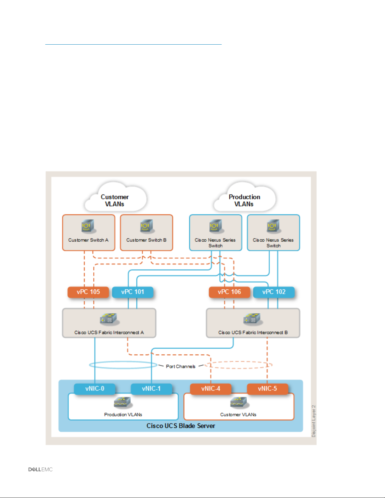
Cisco Nexus 9000 Series NX-OS Software Configuration Guide
Adding vPCs to VLANs for Disjoint Layer 2 networks
Add vPCs to VLANs for Disjoint Lyer 2 networks to define the VLANs that pass over specific uplinks using
the Cisco UCS Manager.
About this task
All VLANs must be explicitly assigned to an uplink, including VLANs added after initial deployment.
Otherwise, a VLAN is allowed to travel over all uplinks, which breaks the disjoint layer 2 concept.
Cisco vPCs 101 and 102 are production uplinks that connect to Cisco Nexus switch. Cisco vPCs 105 and
106 are customer uplinks that connect to external switches. If you use Ethernet performance port
channels (103 and 104 by default), vPCs 101 through 104 should have the same VLANs assigned.
Managing networking resources | 48
Page 49

Before you begin
The procedure provides an example scenario for adding port channels to VLANs for Disjoint Layer 2
networks.
Obtain the vPCs, VLANs, and VLAN-to-port channel assignments.
Procedure
1 Log on to the Cisco UCS Manager.
2 To assign VLANs to vPCs 101 and 105 in fabric A, perform the following:
a Select the LAN tab.
b Select the LAN node.
c From the LAN Uplinks Manager tab, select VLANs > VLAN Manager.
d Select Fabric A.
e In the Port Channels and Uplinks tab, select Port-Channel 101.
f In the VLANs table, select the VLANs to assign to port channel 101. Use the CTRL key to
select more than one VLAN.
g Click Add to VLAN and OK
h In the Port Channels and Uplinks tab, select Port-Channel 105.
i In the VLANs table, select the VLANs to assign to port channel 105.
j Click Add to VLAN and OK.
k Verify that vPCs 101 and 105 (Fabric B) appear under all required VLANs. Refer to Viewing
vPC assigned to VLANs for Disjoint Layer 2 networks.
3 To assign VLANs to vPCs 102 and 106 in fabric B, perform the following:
a In VLAN Manager Navigation window, select the LAN tab.
b Select the LAN node.
c In the Work window, select the LAN Uplinks Manager link on the LAN Uplinks tab.
d In the LAN Uplinks Manager, select VLAN Manager.
e Select Fabric B.
f In the Port Channels and Uplinks tab, select Port-Channel 102.
g In the VLANs table, select the VLANs to assign to port channel 102. Use the CTRL key to
select more than one VLAN.
h Select Add to VLAN and click OK.
i In the Port Channels and Uplinks tab, select Port-Channel 106.
49 | Managing networking resources
Page 50

j In the VLANs table, select the VLANs to assign to vPC 106.
k Select Add to VLAN and click OK.
l Verify that vPCs 102 and 106 (Fabric B) appear under all required VLANs.
Related information
Viewing vPCs assigned to VLANs for Disjoint Layer 2 networks (see page 50)
Removing vPCs from VLANs for Disjoint Layer 2 networks (see page 50)
Configure upstream disjoint layer 2 network
Viewing vPCs assigned to VLANs for Disjoint Layer 2 networks
Verify that vPCs have been assigned to VLANs.
Procedure
1 Log on to the Cisco UCS Manager.
2 In the Navigation window, select the LAN tab.
3 On the LAN tab, select the LAN node.
4 In the Work window, select the LAN Uplinks Manager link on the LAN Uplinks tab.
5 In the LAN Uplinks Manager, select VLANs > VLAN Manager.
6 Click Fabric A or Fabric B to view the vPCs and VLANs on that fabric interconnect.
7 In the VLANs table, expand the appropriate node and the VLAN for which you want to view the
assigned ports or vPCs.
Related information
Adding vPCs to VLANs for Disjoint Layer 2 networks (see page 48)
Removing vPCs from VLANs for Disjoint Layer 2 networks (see page 50)
Configuring upstream disjoint layer 2 networks
Removing vPCs from VLANs for Disjoint Layer 2 networks
Remove vPCs from VLANs in a Disjoint Layer 2 network.
Managing networking resources | 50
Page 51

About this task
If you remove all port or vPC interfaces from a VLAN, the VLAN returns to the default behavior and data
traffic on that VLAN flows on all uplink ports and vPCs. Depending upon the configuration in the Cisco
UCS domain, this default behavior can cause Cisco UCS Manager to drop traffic for that VLAN. To avoid
this, either assign at least one interface to the VLAN or delete the VLAN.
Procedure
1 Log on to the Cisco UCS Manager.
2 In the Navigation window, select the LAN tab.
3 On the LAN tab, select the LAN node.
4 In the Work window, select the LAN Uplinks Manager link on the LAN Uplinks tab.
5 In the LAN Uplinks Manager, select VLANs > VLAN Manager.
6 Click Fabric A or Fabric B to view the vPCs and VLANs on that fabric interconnect.
7 In the VLANs table, expand the appropriate node and the VLAN from which you want to remove
the assigned ports or vPCs.
8 Select the port or vPC that you want to remove from the VLAN.
Hold down the Ctrl key to click multiple ports or vPCs.
9 Click Remove from VLAN.
10 If a confirmation dialog box appears, click Yes.
11 Click Apply if you want to continue to work in the VLAN Manager or click OK to close the window.
Related information
Adding vPCs to VLANs for Disjoint Layer 2 networks (see page 48)
Viewing vPCs assigned to VLANs for Disjoint Layer 2 networks (see page 50)
Configuring upstream disjoint layer 2 networks
Upgrading Cisco Nexus switch software
Upgrade the system image on the Cisco Nexus 3000 Series Switches or Cisco Nexus 9000 Series
Switches.
About this task
Back up the original configuration by typing: copy running-config startup-config
•
Verify that the configuration has been updated and back up the new configuration
•
51 | Managing networking resources
Page 52

There are two switches that require upgrades. Some operational checking is recommended after
•
the first switch is upgraded to ensure that a platform outage does not occur before upgrading the
second switch.
IPv4 addresses are supported on Vblock Systems and VxBlock Systems. IPv6 addresses are supported
on VxBlock Systems.
Before you begin
Refer to the Cisco website to access the software upgrade code and review release notes.
Depending on the currently running release, a multi-step upgrade may be required. To verify whether
multiple upgrade steps are required, refer to the section in the release notes titled Upgrading or
Downgrading to a new release.
Obtain console (terminal) access and management IPv4/IPv6 access.
•
Obtain a Cisco account to download images.
•
Verify there is an SCP, TFTP, FTP or SFTP server to upload the Cisco NX-OS image to the
•
switch.
Procedure
1 Go to Cisco Support to download the Cisco NX-OS bin file system software for the Cisco Nexus
series switch.
2 Upload the file to the switch with the copy server (TFTP, SCP, FTP, or SFTP) being used.
3 To back up the switch running the configuration, type: copy running-config startup-
config
4 To verify the switch has enough space for the new image, type: Switch-A# dir bootflash:
5 If there is not enough space, type: delete bootflash:filename
6 To copy the updated images to the switch, type: Switch (config)# copy <ftp | scp>:
bootflash:copy ftp: bootflash:
a Type the filename of the nxos bin file from the Cisco download site. For example, nxos.
7.0.3.I4.1.bin
b For VRF, type: management.
c Type the hostname of the SCP or FTP server.
d Type the username and password. The system copies the images to the switch, and the
following message appears:
***** Transfer of file Completed Successfully *****
7 To view the impact of the upgrade, type: Switch-A(config)# show install all impact
nxos bootflash:/// nxos.7.0.3.I4.1.bin
Managing networking resources | 52
Page 53

8 If you are performing a disruptive upgrade, following warning appears:
Switch will be reloaded for disruptive upgrade.
Do you want to continue with the installation (y/n)? [n] y
Install is in progress, please wait.
Performing runtime checks.
[####################] 100% -- SUCCESS
Setting boot variables.
[####################] 100% -- SUCCESS
Performing configuration copy.
[####################] 100% -- SUCCESS
Module 1: Refreshing compact flash and upgrading bios/loader/bootrom/power-seq.
Warning: please do not remove or power off the module at this time.
Note: Power-seq upgrade needs a power-cycle to take into effect.
On success of power-seq upgrade, SWITCH OFF THE POWER to the system and then, power
it up.
Note: Micro-controller upgrade needs a power-cycle to take into effect.
On success of micro-controller upgrade, SWITCH OFF THE POWER to the system and then,
power it up.
[####################] 100% -- SUCCESS
Finishing the upgrade, switch will reboot in 10 seconds.
Switch(config)# 2011 Sep 8 18:16:43 Switch Sep 8 18:16:43 %KERN-0-SYSTEM_MSG:
Shutdown Ports.. - kernel
2011 Sep 8 18:16:43 Switch Sep 8 18:16:43 %KERN-0-SYSTEM_MSG: writing reset reason
49, - kernel
Broadcast message from root (Thu Sep 8 18:16:43 2011):
The system is going down for reboot NOW!
9 Type Y to continue with the installation.
10 When the switch reboots, to verify that the updated version of the software is running, type: show
version
11 From the returned version information, verify the system image file that appears is the correct
version.
What to do next
Some operational checking is recommended after upgrading the first switch to ensure that a platform
outage is not experienced before upgrading the second switch.
When you have verified that the configuration has been updated successfully, create a backup of the new
configuration.
Related information
Cisco Nexus 3000 Series NX-OS Software Upgrade and Downgrade Guide, Release 7.x
Cisco Nexus 9000 Series NX-OS Software Upgrade and Downgrade Guide, Release 7.x
Downgrading Cisco Nexus switch software
Downgrade Cisco Nexus switch software to restore the original version after a failed upgrade.
53 | Managing networking resources
Page 54

Procedure
To reverse a Cisco Nexus series switch software upgrade, perform the upgrade steps using the earlier
version of the software.
Related information
Cisco Nexus 3000 Series NX-OS Software Upgrade and Downgrade Guide
Cisco Nexus 9000 Series NX-OS Software Upgrade and Downgrade Guide
Managing networking resources | 54
Page 55

Managing Cisco MDS switches
Upgrading Cisco MDS switch software
Upgrade or downgrade the firmware on the Cisco MDS series switches.
About this task
IPv4 addresses are supported on Vblock Systems and VxBlock Systems. IPv6 addresses are supported
on VxBlock Systems.
Before you begin
Perform operational checking after upgrading the first switch to ensure that a platform outage
•
does not occur before upgrading the second switch.
Obtain console (terminal) and management IPv4/IPv6 access.
•
Obtain a Cisco account to download any images.
•
Access a SCP, TFTP, FTP, or SFTP server to upload the Cisco NX-OS image to the switch.
•
Obtain software upgrade code on the Cisco website.
•
Review Cisco release notes before any upgrade.
•
Procedure
1 To log on to the Cisco MDS switch and save the running configuration, type: copy run
tftp://tftp-server/filename or copy run ftp://ftp server/filename
2 From the
3 From the Products list, select Cisco IOS and NX-OS Software.
4 Select Download Software.
5 Select the switch and required software version, and select Download Now. Sample kickstart
filenames are as follows:
—
—
Sample NX-OS file names are as follows:
—
Cisco Support website, under Select a Task, select Download Software.
m9300-s1ek9-kickstart-mz-npe.6.2.13b.bin
m9100-s5ek9-kickstart-mz.6.2.9a.bin
m9300-s1ek9-mz.6.2.13.bin
—
m9100-s5ek9-mz.6.2.9a.bin
—
m9700-sf3ek9-mz.6.2.9a.bin
6 Download Kickstart and system software with the copy server .
55 | Managing Cisco MDS switches
Page 56

7 To copy the Kickstart and the system files from the FTP copy server to the fabric switch, from the
MDS# prompt perform the following:
a To access the bootflash directory, type: cd bootflash:
b To verify free space, type dir
c To copy the files, type:
copy ftp://ftp_server_addr/filename.bin
filename.bin
copy ftp://ftp_server_addr/filename.bin
filename.bin
8 To verify storage space on the standby supervisor, from the MDS# prompt, type:
cd bootflash:
dir
9 While in configure mode, depending on the Converged System, from the from the
VSJ3X2M9148SB# prompt, type: configure terminal
Type configuration commands, one per line. End with CNTL/Z.
VSJ3X2M9148SB(config)# no logging level all
10 To verify the impact of the firmware upgrade, depending on the switch, perform the following:
For VBxx-9396S-A#, type:
show install all impact kickstart m9300-s1ek9-kickstart-mz-npe.
6.2.13b.bin system m9300-s1ek9-mz.6.2.13b.bin
For VBxx-9706-A#, type: show install all impact kickstart m9700-sf3ek9-
kickstart-mz.6.2.9a.bin system m9700-sf3ek9-mz.6.2.9a.bin
For VSJ3X2M9148B#, type: show install all impact kickstart m9100-s5ek9-
kickstart-mz.6.2.9a.bin system m9100-s5ek9-mz.6.2.9a.bin
11 To view the entire upgrade process, perform the upgrade using the console port. You can log
your session to a file for future reference.
12 To install the system and kickstart software, type:install all kickstart <kickstart
file> system <system file> For example:
—
MDS9396S-A# install all m9300-s1ek9-kickstart-mz-npe.6.2.13b.bin
system m9300-s1ek9-mz.6.2.13b.bin
—
MDS9706-A# install all kickstart m9700-sf3ek9-kickstart-mz.
6.2.9a.bin system m9700-sf3ek9-mz.6.2.9a.bin
—
VSJ3X2M9148B# install all kickstart m9100-s5ek9-kickstart-mz.
6.2.9a.bin system m9100-s5ek9-mz.6.2.9a.bin
13 After the update completes, to view the status of the install, type: show install all status
Managing Cisco MDS switches | 56
Page 57

Downgrading Cisco MDS switch software
Downgrade Cisco MDS switch software to restore the original version after a failed upgrade.
Procedure
Refer to the release notes section Downgrading Your Cisco MDS SAN-OS Software Image and follow the
guidelines before downgrading the software.
Related information
Cisco.com
Configuring a VSAN
Configure a VSAN and assign FC interfaces.
About this task
IPv4 addresses are supported on Vblock Systems and VxBlock Systems. IPv6 addresses are supported
on VxBlock Systems.
Before you begin
Verify that the Cisco MDS switch is up and reachable through the console or management
•
connection
Obtain required VSANs, names, and FC interfaces that need to be assigned to the VSANs
•
Obtain Cisco MDS switch IPv4/IPv6 address/console information, log on credentials and access
•
method (SSH/TELNET)
Name VSANs to identify usage. For example, for VSAN 10: SAN_A.
•
Procedure
1 Log on to the Cisco MDS switch.
2 To view VSANs, type: show vsan
3 To enter the global configuration mode and start the configuration, type: switch# configure
terminal
4 To configure the database for VSAN, type: switch(config)# vsan database
5 To specify the VSAN being created, type: switch(config-vsan-db)# vsan vsan_id
6 To specify the VSAN name, type: switch(config-vsan-db)# vsan vsan_id name
vsan_name
57 | Managing Cisco MDS switches
Page 58

7 To assign an FC interface to the VSAN, type: switch(config-vsan-db)# vsan vsan_id
interface fc slot
8 To update the interface with the VSAN, type: switch(config-vsan-db)# vsan vsan_id
fc slot
Related information
Configuring and Managing VSANs
Removing a VSAN
Remove a VSAN and associated FC interfaces.
About this task
IPv4 addresses are supported on Vblock Systems and VxBlock Systems. IPv6 addresses are supported
on VxBlock Systems.
Before you begin
Verify that the Cisco MDS switch is reachable through the console or management connection.
•
Obtain required VSANs, names, and FC interfaces.
•
Obtain Cisco MDS switch IPv4/IPv6 address/console information, log on credentials, and access
•
method (SSH/TELNET).
Procedure
1 Log on to the Cisco MDS switch.
2 To view VSANs, type: show vsan
3 To enter the global configuration mode and start the configuration, type: switch# configure
terminal
4 To configure the database for VSAN, type: switch(config)# vsan database
5 To delete a VSAN, type: no vsan vsan_id
Related information
Configuring and Managing VSANs
Configuring a domain ID and priority for a VSAN
Setting the domain ID and priority ensures the switch takes a role of a principal switch in that VSAN. The
domain ID in the VSAN does not get changed during a fabric merge.
Managing Cisco MDS switches | 58
Page 59

About this task
IPv4 addresses are supported on Vblock Systems and VxBlock Systems. IPv6 addresses are supported
on VxBlock Systems.
Before you begin
A unique domain ID must be assigned to the new VSAN added to the switch. When a new VSAN
•
is added to a switch in a fabric, the domain manager is used to assign a domain ID and priority to
the VSAN. When a switch boots up or joins a new fabric, the switch can request a specific
domain ID or take any available domain ID.
Verify that the Cisco MDS switch is up and reachable through the console or management
•
connection
Obtain required VSANs, names, and FC interfaces that need to be assigned to the VSANs
•
Verify that the domain ID of the new VSAN matches the domain ID of the existing VSAN for this
•
switch
Obtain Cisco MDS switch IPv4/IPv6 address/console information, log on credentials and access
•
method (SSH/TELNET)
Procedure
1 Log on to the Cisco MDS switch.
2 To view VSANs, type: show vsan
3 To view the domain ID of the existing VSAN on the switch, type: switch#show fcdomain
domain-list
4 To enter the global configuration mode and start the configuration, type: switch# configure
terminal
5 To assign a domain ID, type: switch# fcdomain domain domain_id static vsan
vsan_id
6 To assign a priority, type: switch# fcdomain priority 2 vsan vsan_id
Removing a domain ID and priority from a VSAN
Remove the domain ID and priority to ensure the switch is no longer a principal switch in that VSAN. This
enables the domain ID in that VSAN to be changed during a fabric merge.
Procedure
1 To enter the global configuration mode and start the configuration, type: switch# configure
terminal
2 To view the VSAN database, type: switch(config)# vsan database
3 To delete a VSAN, type no vsan vsan_id
59 | Managing Cisco MDS switches
Page 60

Enabling FC interfaces
Enable FC interfaces on the Cisco MDS switch.
About this task
IPv4 addresses are supported on Vblock Systems and VxBlock Systems. IPv6 addresses are supported
on VxBlock Systems.
Before you begin
Verify that the Cisco MDS switch is up and reachable through the console or management
•
connection.
Obtain the FC interfaces IDs.
•
Obtain Cisco MDS Switch IPv4/IPv6 address/console information, log on credentials and access
•
method (SSH/TELNET)
Procedure
1 Log on to the Cisco MDS switch.
2 To start the configuration, type: switch-A# config terminal
3 To configure the interface, type: switch-A(config)# interface fc interface_id
4 To apply for a license, type: switch-A(config-if)# port-license acquire
5 To enable the interface, type: switch-A(config-if)# no shutdown
6 To verify that the interface is up, type: show interface fc interface_id
Disabling FC interfaces
Disable FC interfaces on the Cisco MDS switch.
About this task
IPv4 addresses are supported on Vblock Systems and VxBlock Systems. IPv6 addresses are supported
on VxBlock Systems.
Before you begin
Verify that the Cisco MDS switch is up and reachable through the console or management
•
connection.
Obtain the FC interface IDs.
•
Obtain Cisco MDS Switch IPv4/IPv6 address/console information, log on credentials and access
•
method (SSH/TELNET)
Managing Cisco MDS switches | 60
Page 61

Procedure
1 Log on to the Cisco MDS switch.
2 To enter configuration mode, type: switch-A# config terminal
3 To specify the interface, type: switch-A(config)# interface fc interface_id
4 To disable the interface, type: switch-A(config-if)# shutdown
Moving licenses between FC interfaces
Move licenses between FC interfaces on Cisco MDS switches.
About this task
IPv4 addresses are supported on Vblock Systems and VxBlock Systems. IPv6 addresses are supported
on VxBlock Systems.
Before you begin
Verify that the Cisco MDS switch is up and reachable through the console or management
•
connection.
Obtain the FC interfaces IDs.
•
Obtain Cisco MDS switch IPv4/IPv6 address/console information, log on credentials and access
•
method (SSH/TELNET).
Procedure
1 Log on to the Cisco MDS switch.
2 To view the port licenses, type: show port-license
3 To start the configuration, type: Switch-A# config terminal
4 To configure the interface where license is being moved from, type: Switch-A(config)#
interface fcinterface_id
5 To disable the license on that interface, type: Switch-A(config-if)# no port-license
6 To exit, type: Switch-A(config-if)# exit
7 To configure the interface where the license is being moved to, type: Switch-A(config)#
interface fcinterface_id
8 To acquire the license on that interface, type: Switch-A(config-if)# port-license
acquire
9 To end the configuration, type: Switch-A(config-if)# end
10 To verify that appropriate ports have enabled licenses, type: show port-license
61 | Managing Cisco MDS switches
Page 62

Related information
Disabling port licenses (see page 62)
Cisco MDS 9000 Family NX-OS Licensing Guide, Release 6.x
Disabling port licenses
Port licenses can be disabled and moved to other interfaces.
About this task
To configure the switch for other SAN features, refer to the Cisco MDS 9000 NX-OS Fabric Configuration
Guide.
Procedure
1 To start the configuration, type: Switch-A# config terminal
2 To configure the interface where license is being moved, type: Switch-A(config)#
interface fcinterface_id
3 To disable the license on that interface, type: Switch-A(config-if)# no port-license
4 To exit, type: Switch-A(config-if)# end
Related information
Cisco MDS 9000 NX-OS Fabric Configuration Guide
Guidelines and configuration recommendations
Best practices apply when configuring Cisco MDS switches.
The following best practices apply when configuring Cisco MDS switches:
The Cisco MDS 9148S Multilayer Fabric Switch use a three-forwarding engines architecture.
•
—
Each forwarding engine has a total of 2,852 TCAM entries that limits the number of hosts
supported per forwarding engine.
—
Support a maximum of 64 servers per forwarding engine.
Managing Cisco MDS switches | 62
Page 63

—
A maximum of 192 servers per switch are supported if spread across the three forwarding
engines (e0-e2) on the switch.
The Cisco MDS 9396S 16G Multilayer Fabric Switch and Cisco MDS 9706 Multilayer Director
•
switches use dynamic port mapping for device connectivity.
The Cisco MDS 9396S 16G Multilayer Fabric Switch and MDS 9706 Multilayer Directors do not
•
have the TCAM exhaustion issue.
The Cisco MDS 9396S 16G Multilayer Fabric Switch is built on the same ASICs as the Cisco
•
MDS 9700 Series Switch.
—
The Cisco MDS 9396S 16G Multilayer Fabric Switch has 12 forwarding engines.
—
Each forwarding engine has a total of 49,136 TCAM entries.
—
A total of 589,632 TCAM entries are available per switch.
To distinguish servers on the compute side, create multiple pools or blocks of 64 WWNs instead
•
of one large pool/block of 128 identifiers. Essentially, each WWPN would have a distinguishing
value relative to its corresponding N-Port-channel.
The vHBA templates should ensure that servers are pinned to the appropriate N-Port-channels.
•
Refer to Cisco bug CSCuz11494 when bringing up an Fport-channel-trunk between a Cisco MDS and a
UCS switch.
Related information
Cisco bug - CSCuz11494
Zoning guidelines
Zoning guidelines apply when using Cisco MDS switches.
The following zoning guidelines apply:
Use smart zoning on the Cisco MDS switches (unless restricted by the HBA device vendor).
•
Use enhanced zoning.
•
Use device alias and FC alias
•
There is a fabric wide, limit of 8000 device aliases, and 2000 FC aliases.
Zone member types = FC alias
•
FC alias member types = device alias. Identify the device alias member as the target or init.
•
63 | Managing Cisco MDS switches
Page 64

Managing storage resources
Creating a storage pool
Storage pools can be added to the Dell EMC Unity storage array for high access applications.
About this task
Create fewer, larger storage pools to accommodate general usage of the capacity. Create additional pools
only when a specific application requires a significantly different I/O profile, such as an All-Flash pool for a
database or high access application. Block and file data resides in the same storage pools based on
capacity and performance requirements, not access characteristics.
Before you begin
For Hybrid models, verify that unused, appropriate drives are available in the Dell EMC Unity storage
array to be used as hot spares.
Procedure
1 Log on to the Dell EMC Unity storage array where you want to create the storage pool.
2 Select Storage > Pools.
3 Click + to create the storage pool.
4 Using the wizard, select tiers, RAID protection and drives to create the new storage pool.
Notes:
—
Hybrid models display the default RAID configuration for your tier selection.
—
In All-Flash models, the RAID configuration is based on number of drives in the pool and is
not configurable.
Expanding a storage pool
Expand a storage pool on the Dell EMC Unity storage array to increase capacity to grow existing LUNs or
create new ones.
Before you begin
Verify that storage pools exist and disk drives are available to expand the storage pool.
Procedure
1 Log on to the Dell EMC Unity storage array on which you want to expand the storage pool.
2 Select Storage > Pools.
3 Select the check box for the pool you want to expand and click Expand.
Managing storage resources | 64
Page 65

4 Using the wizard, add tiers and disks to the existing pool.
Notes:
—
Hybrid models display the default RAID configuration for your tier selection.
—
In All-Flash models, the RAID configuration is based on number of drives in the pool and is
not configurable.
Allocating block storage
On the Dell EMC Unity storage array, you can present storage to one or more hosts.
About this task
You can present additional storage to one or more hosts in the following ways:
Present new LUNs from the same or a different pool
•
Extend existing LUNs to present additional capacity.
•
Present existing LUNs to additional hosts.
•
Procedure
1 Log on to the Dell EMC Unity storage array on which you want to allocate storage.
2 Select Storage > Block > LUNs.
3 To allocate additional block storage, perform the following:
—
To create a new LUN, proceed to step 4.
—
To extend an existing LUN, proceed to step 6.
—
To add additional hosts to an existing LUN, proceed to step 8.
4 To create a new LUN, click +.
5 Using the wizard, perform the following steps:
a Type the name and description.
b Select the storage pool, tiering policy, capacity, desired host I/O limit and, if necessary,
compression.
Enable compression on data LUNs only if you have determined that the application
is suited to handle compression.
c Set the designated access for hosts.
d Set the defined snapshot and replication options.
65 | Managing storage resources
Page 66

6 To extend or modify an existing LUN, click the check box of the LUN and perform the following
steps:
a Click the pencil icon.
b From the General tab, modify the name, description, size, or SP owner, and enable or
disable compression.
Enable compression on data LUNs only if you have determined that the application
is suited to handle compression.
7 To compress an existing LUN, enable the check box of the LUN and perform the following steps:
a Click the pencil icon.
b Select Compress Now.
The Compress Now operation compresses data by creating a move session to move the
LUN within the same pool.
Pool performance may be impacted during the move operation.
8 To add additional hosts, perform the following:
a Click the pencil icon.
b From the Access tab, click + to modify the hosts.
c Follow the wizard to create new hosts, grant access to existing hosts, and modify the type of
access to the LUN and its snapshots.
Managing NFS
Creating a NAS server
NAS servers can share file storage over a variety of protocols including CIFS/SMB, NFS, and FTP.
About this task
To allocate file storage, first create a NAS server on the Dell EMC Unity storage array. The NAS server is
a standalone service with dedicated network interfaces (IPv4/IPv6 address information) to share file
through single or multiple NAS protocols. The network interfaces can share a common physical
connection to the LAN with other NAS servers.
IPv4 addresses are supported on Vblock Systems and VxBlock Systems. IPv6 addresses are supported
only on VxBlock Systems.
Separate, dedicated physical links are required for internal or external NAS servers. Internal servers
provide file shares to hosts and VMs inside the Converged System. External servers connect to LAN
devices outside of the Converged System.
A NAS server must be assigned to run primarily on one SP. In the event of an SP outage, the NAS server
automatically fails over to the other SP. To balance workload across SPs, allocate NAS servers in pairs,
Managing storage resources | 66
Page 67

one on SP-A and the other on SP-B. Each server shares different file systems. IP multi-tenancy is
optional and can be configured depending on the use case.
Procedure
1 Log on to the Dell EMC Unity storage array where you want to create a NAS server.
2 Select Storage > File>NAS Servers.
3 Click + to create a new server.
4 Using the wizard, perform the following:
a Type the name, tenant, storage pool, and SP.
b Select the Ethernet port (physical link), IPv4/IPv6 information, and VLAN.
c Select the NFS, SMP, or FTP protocols.
d Select the NIS and DNS servers.
5 Create a second NAS server with similar characteristics on the other SP.
Creating a file system
Specify the file system size, storage type, the NAS server, and other characteristics, such as snapshots
and replication.
Procedure
1 Log on to the Dell EMC Unity storage array where you want to create a file system.
2 Select Storage > File>File Systems.
3 Click + to create a new file system.
4 Using the wizard, perform the following:
a Set the NAS protocol and server.
b Type the name and description of the file system.
c Set the pool, capacity, and tiering policy.
d Type the initial share information.
e Set the snapshot and replication options.
Creating a tenant
Create a tenant by specifying the name, optional UUID, and adding VLANs.
Before you begin
67 | Managing storage resources
Page 68

Procedure
1 Log on to the Dell EMC Unity storage array where you want to create a tenant.
2 Select Storage > File > Tenants.
3 Click + to create a new tenant.
4 Using the wizard, perform the following:
a Type the name of the tenant.
b Optionally, specify a manual UUID by enabling the check box and entering a UUID.
c Select Add to enter a VLAN.
d Repeat step c for each additional VLAN.
Creating NFS shares
An NFS share defines the access of a file system on the array, including the share name and
authorization access to the file system.
About this task
An NFS share can have a defined default access type such as No Access.
Procedure
1 Log on to the Dell EMC Unity storage array where you want to create the NFS share.
2 Select Storage > File > NFS Shares.
3 Click + to create a NFS share.
4 Using the wizard, perform the following:
a Select the file system to be shared.
b Type the share name, description, and local path on the NAS server.
c Set the default access and defined access rights.
Managing storage resources | 68
Page 69

Managing VMware vSphere 6 with IPv6
VMware vSphere 6 does not support an IP dual stack network configuration. vSphere 6.5 does not
currently support IPv6.
Enable IPv6 for all nodes and components except for the following VMware vSphere 6.0 features:
VMware feature with IPv6 limitation Workaround
IPv6 addresses for VMware vSphere ESXi hosts and
VMware vCenter Server that are not mapped to FQDNs
on the DNS server.
Virtual volumes N/A
PXE booting as a part of Auto Deploy and Host Profiles PXE boot a VMware vSphere ESXi host over IPv4 and
Connection of VMware vSphere ESXi hosts and the
VMware vCenter Server Appliance to Active Directory.
NFS 4.1 storage with Kerberos. You can use NFS 4.1 with AUTH_SYS.
Authentication Proxy N/A
Connection of the VMware vSphere Management
Assistant and vSphere Command-Line Interface to
Active Directory.
Use VMware vSphere Client to enable IPv6 on VMware
vSphere features.
VMware vSphere ESXi Installing I/O filters on IPv6 setup
does not publish its capabilities to VPXD. After
successful installation of an I/O filter through VIM API,
the installed filter is not able to publish the filter
capabilities to VPXD. You are unable to attach the filter
profile to any disks as there are no capabilities published
to the VMware vSphere Storage Policy Based
Management (SPBM).
Use FQDNs or verify IPv6 addresses are mapped to
FQDNs on the DNS servers for reverse name lookup.
configure the host for IPv6 using host profiles.
You can use Active Directory over LDAP as an identity
source in VMware vCenter Single Sign-On.
You can connect to AD over LDAP.
You can use the VMware vSphere Web Client to enable
IPv6 for VMware vSphere features.
N/A
69 | Managing VMware vSphere 6 with IPv6
Page 70

Managing VMware vSphere ESXi 5.5 and 6.x
Installing the latest VMware vSphere ESXi patch (vSphere
6.0)
Install the latest supported VMware vSphere ESXi patch.
About this task
Refer to the Converged Systems Release Certification Matrix and Converged Systems Release Notes for
the latest information about installing supported VMware vSphere ESXi releases.
The following releases of VMware vSphere ESXi are supported:
6.0
•
Dell EMC recommends that you use the VMware Update Manager (VUM) if upgrading to a newer
supported build, however, you can use the CLI to install the patch.
Do not use this procedure for major upgrades.
Before you begin
Verify that the host is in Maintenance mode and all the VMs are evacuated.
•
Verify the software compatibility for the Cisco Nexus 1000V Series Switch or VDS, PowerPath
•
VE, and the build to which you are upgrading. You might need to upgrade third-party software
prior to updating to the latest release of VMware ESXi.
Obtain the Release Certification Matrix and Release Notes with the version to which you want to
•
update. Look for the supported version of the VMware patch (build) in the Virtualization section.
Determine which patch to install. Refer to the appropriate Release Certification Matrix and
•
Release Notes.
Procedure
1 Download the latest VMware vSphere ESXi patch supported for this release.
2 Using a browser, navigate to https://www.vmware.com/patchmgr/
findPatchByReleaseName.portal.
3 In the Search by Product menu, select ESXi (Embedded and Installable) | 5.x.0 or 6.0.
4 Click Search.
5 Select and download the latest supported VMware vSphere ESXi patch.
6 Install the patch as described in Patching VMware vSphere ESXi hosts with the VMware Update
Manager.
Managing VMware vSphere ESXi 5.5 and 6.x | 70
Page 71

7 To verify the installation, on the VMware vSphere ESXi host Splash Screen (through Cisco UCS
vKVM), confirm that the build number matches the update just applied.
8 Reboot the VMware vSphere ESXi host.
Installing the latest VMware vSphere ESXi patch (vSphere
6.5)
Install the latest supported VMware vSphere ESXi patch.
About this task
After you install the latest patch, when you update a VMware vSphere ESXi host to a newer supported
build, the host no longer shares the same build.
Dell EMC recommends that you use the VMware Update Manager (VUM) if upgrading to a newer
supported build, however, you can use the CLI to install the patch.
Do not use this procedure for major upgrades.
Before you begin
Verify that the host is in Maintenance mode and all the VMs are evacuated.
•
Verify the software compatibility for the VMware VDS, PowerPath VE, and the build to which you
•
are upgrading. You might need to upgrade third-party software prior to updating to the latest
release of VMware ESXi.
Obtain the Release Certification Matrix and Release Notes with the version to which you want to
•
update. Look for the supported version of the VMware patch (build) in the Virtualization section.
Determine which patch to install. Refer to the appropriate Release Certification Matrix and
•
Release Notes.
Procedure
1 Download the latest VMware vSphere ESXi patch supported for this release.
2 Using a browser, navigate to https://www.vmware.com/patchmgr/
findPatchByReleaseName.portal.
3 In the Search by Product menu, select ESXi (Embedded and Installable) 6.5.
4 Click Search.
5 Select and download the latest supported VMware vSphere ESXi patch.
6 Install the patch as described in VMware knowledge base article 2008939.
7 To verify the installation, on the VMware vSphere ESXi host Splash Screen (through Cisco UCS
vKVM), confirm that the build number matches the update just applied.
8 Reboot the VMware vSphere ESXi host.
71 | Managing VMware vSphere ESXi 5.5 and 6.x
Page 72

Configuring advanced settings for VMware vSphere ESXi (vSphere 6.0)
Configure advanced VMware vSphere ESXi settings for compute servers.
About this task
The following advanced settings are available:
Setting Value to configure Default value to restore for
VMware vSphere 5.5 (if
applicable)
Disk.UseDevic
eReset
NFS.MaxVolu
mes
Net.TcpipHeap
Size
Net.TcpipHeap
Max
NFS performance is enhanced when advanced configuration options are set. Apply NFS options before
connecting any NFS share to the VMware vSphere ESXi hosts.
You can configure the settings on each host individually using the VMware vSphere client or run the
VMware vSphere PowerCLI script to configure the settings on all VMware vSphere ESXi hosts.
Before you begin
If configuring with the following script, verify the VMware PowerCLI is installed on a workstation
•
with administrative access to VMware vCenter.
0 1 1
256 8 8
30 0 0
512 for VMware vSphere 6.0 512 512
Default value to restore for
VMware vSphere 6.0
Obtain the IP address and local root user credentials for the VMware vSphere ESXi host or
•
appropriate administrative credentials to the VMware vCenter.
Procedure
1 In the VMware vSphere client, select the host.
2 Select the Configuration tab.
3 In the Software section, select Advanced Settings.
4 Set the parameters in the window.
5 To configure the settings on each VMware vSphere ESXi host in the VMware vCenter using the
script:
a Verify VMware vSphere PowerCLI is installed on a Microsoft Windows machine.
b Verify you have network access to the VMware vCenter server.
c Copy the script to a .ps1 file on your hard drive.
Managing VMware vSphere ESXi 5.5 and 6.x | 72
Page 73

d Modify the $vcenter variable.
6 Execute the script in the VMware vSphere PowerCLI environment.
This script does NOT set jumbo frames on the vmknics. You must perform jumbo
frame settings manually or using another tool.
##########################################################
# Set NFS advanced settings for all servers in vCenter. If
# hosts were built using UIM, or built manually, this script can
# be run to assist with the configuration of NFS. It does NOT
# set jumbo frames on the vmknics: you must do this by using
# the command line or another tool.
##########################################################
$vcenter = Read-Host "What is the name/IP of the vCenter Server?"
##########################################################
connect-viserver $vcenter
$esxHosts = Get-VMHost | Sort Name
foreach($esx in $esxHosts){
Write-Host "Updating TCP and NFS advanced configuration Settings on $esx"
# Update TCP settings
if((Get-VMHostAdvancedConfiguration -VMHost $esx -Name Net.TcpipHeapSize).Values -ne
"30"){
Set-VMHostAdvancedConfiguration -VMHost $esx -Name Net.TcpipHeapSize -Value 30 Confirm:$false
}
if((Get-VMHostAdvancedConfiguration -VMHost $esx -Name Net.TcpipHeapMax).Values -ne
"128"){
####################################################################
Set-VMHostAdvancedConfiguration -VMHost $esx -Name Net.TcpipHeapMax –Value 512 –
Confirm:$false
# for vSphere 5.5 or 6.0
####################################################################
# Set-VMHostAdvancedConfiguration -VMHost $esx -Name Net.TcpipHeapMax -Value 128 Confirm:$false
# for vSphere 5.1
}
# Update NFS settings
if((Get-VMHostAdvancedConfiguration -VMHost $esx -Name NFS.MaxVolumes).Values -ne
"256"){
Set-VMHostAdvancedConfiguration -VMHost $esx -Name NFS.MaxVolumes -Value 256 -Confirm:
$false
}
if((Get-VMHostAdvancedConfiguration -VMHost $esx -Name NFS.HeartbeatTimeout).Values ne "5"){
Set-VMHostAdvancedConfiguration -VMHost $esx -Name NFS.HeartbeatTimeout -Value 5 Confirm:$false
What to do next
Reboot the VMware vSphere ESXi host(s).
Configuring advanced settings for VMware vSphere ESXi (vSphere 6.5)
Configure advanced VMware vSphere ESXi settings.
73 | Managing VMware vSphere ESXi 5.5 and 6.x
Page 74

About this task
NFS performance is enhanced when advanced configuration options are set. Apply NFS options before
connecting any NFS share to the VMware vSphere ESXi hosts.
You can configure the settings on each host individually using the VMware Host client.
The following advanced settings are available.
Setting Value
Disk.UseDeviceRe
set
NFS.MaxVolumes 256
Net.TcpipHeapSize 32
Net.TcpipHeapMax 512
Before you begin
Obtain the IP address and local root user credentials for the VMware vSphere ESXi host.
•
Procedure
1 Login to VMware Host Client using browser.
2 Click Advanced Settings under the System tab. Search for the parameters displayed in the
table and update the value.
3 Review the updated value in the Advanced Settings section under the System tab using the
VMware Host Client on each VMware vSphere ESXi host.
What to do next
0
Reboot the VMware vSphere ESXi host.
Restoring default values for VMware vSphere ESXi advanced settings (vSphere 6.0)
Use this procedures to restore the advanced settings for VMware vSphere ESXi to their default values.
Procedure
1 In the VMware vSphere client, select the host.
2 Select the Configuration tab.
3 Under Software, select Advanced Settings.
4 Restore the parameters in the window to their default settings.
For parameters that have numerical values, the default setting is most often the
minimum value.
Managing VMware vSphere ESXi 5.5 and 6.x | 74
Page 75

Restoring default values for VMware vSphere ESXi advanced settings (vSphere 6.5)
Use this procedure to restore the advanced settings for VMware vSphere ESXi to their default values.
Procedure
1 In the VMware Host Client, select Manage in navigator pane.
2 Click Advanced Settings under the System tab. Search for the appropriate parameters.
3 Restore the parameters in the window to their default settings.
For parameters that have numerical values, the default setting is most often the
minimum value.
Hardening security on VMware vSphere ESXi hosts
To verify the procedure, review the modified Advanced Settings in the Advanced Settings section
under the Configuration tab using the VMware vSphere Client on each VMware vSphere ESXi host.
Increasing the disk timeout on Microsoft Windows VMs
Increase the amount of time for a Microsoft Windows VM to wait for unresponsive disk I/O operations.
About this task
Increase the disk timeout value to 190 seconds. VMware tools, version 3.0.2 and later sets the
•
value to 60 seconds.
Include this registry setting on all Microsoft Windows VMs and templates to accommodate
•
unresponsive disk I/O operations.
For more information, refer the VMware Knowledge Base entry 1014.
•
Procedure
1 Using the Microsoft regedit application, navigate to HKEY_LOCAL_MACHINE > /System > /
CurrentControlSet > Services > /Disk .
2 Right-click and select New > DWORD (32-bit) Value.
3 Type the value name TimeOutValue. The name is case sensitive.
4 Set the data type to REG_DWORD.
5 Set the data to 190 (decimal).
6 Reboot the VM.
75 | Managing VMware vSphere ESXi 5.5 and 6.x
Page 76

Installing vCenter Server root certificates on web browser (vSphere 6.5)
Install the trusted root certificate authority (CA) certificates.
About this task
Install trusted root certificate authority (CA) certificates. This procedure is applicable for Internet Explorer
only. For browsers other than Internet Explorer, refer to respective browser documentation.
Procedure
1 Open the Internet Explorer web browser and go to https://vcsa_fqdn.
2 In the vCenter getting started page, select Download trusted root CA certificates and save the
file locally.
3 Unzip the downloaded files.
4 Right click on each .crt file and click Open. In the pop up dialog click Install Certificate. Select
Local Machine and click Next, Next, and Finish.
For more information, refer the VMware Knowledge Base article 2108294.
Setting up Java and Internet Explorer on the management workstation or VM (vSphere 6.x)
Set up Java and Internet Explorer version 11 on the management workstation or VM (element manager) if
Unisphere or other web-based applications fail to launch. Configure the Java security setting to support
web-based applications.
Before you begin
vSphere 6.0: Ensure Java version 7 Update 51 or later is installed on the management
•
workstation or VM.
vSphere 6.5: Ensure Java version 8 Update 131 or later is installed on the management
•
workstation or VM.
Ensure the Java security level complies with your corporate security policy.
•
Procedure
1 Using administrative privileges, log on to Microsoft Windows on the management workstation or
virtual machine.
2 Navigate to the Java Windows Control Panel.
3 Select the Security tab.
4 Set the security level to the lowest setting (least secure).
Managing VMware vSphere ESXi 5.5 and 6.x | 76
Page 77

5 Click Edit Site List... which opens in the Exception Site List popup window.
6 Add the URLs of web-based applications. For example: https://
ip_address_of_web_based_application
7 Click OK to close the Exception Site List popup window.
8 Click OK to close the Java Windows Control Panel.
77 | Managing VMware vSphere ESXi 5.5 and 6.x
Page 78

Managing VMware vCenter SSO for VMware vSphere 6.x
VMware vCenter SSO is an authentication mechanism used to configure security policies and lock out or
disable an account for VMware vSphere 6.x. Default policies do not require modification. You may have to
modify policies or accounts if regulations require different policies or if you are troubleshooting a problem.
VMware vCenter SSO overview
VMware vCenter SSO is an authentication mechanism used to configure security policies and lock out or
disable an account for VMware vSphere. Default policies do not require modification. However, you might
have to modify policies or accounts if regulations require different policies or if you are troubleshooting a
problem.
Unlocking and resetting the VMware vCenter SSO administrator password
The VMware vSphere knowledge base article KB 2034608 contains instructions to unlock a VMware
vCenter SSO administrator account.
About this task
For security purposes, the VMware vCenter administrator account is locked after three failed log on
attempts.
Procedure
Follow the procedure in the VMware knowledge base article 2034608.
Managing the lockout status of VMware vCenter SSO
View the lockout status of a VMware vCenter SSO account for VMware vSphere.
Procedure
1 Log on to the VMware vSphere Web Client as an SSO administrator. By default, the user is
administrator@vsphere.local.
2 From the home page, select Administration > Single Sign-On > Users and Groups.
3 Each tab shows information from the identity sources about configured accounts that are on the
system. Select the Users tab.
4 The Locked or Disabled columns show the status of each configured SSO account. Right-click
the appropriate account and select Enable/Disable or Unlock.
The Locked Users and Disabled Users tabs show information for the identity sources
only.
Managing VMware vCenter SSO for VMware vSphere 6.x | 78
Page 79

5 Click Yes to confirm.
Managing VMware vCenter SSO default password policies
Manage the VMware vCenter SSO default password policies for VMware vSphere.
About this task
By default, the SSO passwords expire after 365 days, including the SSO administrator password. You can
modify the expiration policy to manage administrative passwords.
Procedure
1 Log on to the VMware vSphere Web Client as an SSO administrator. By default, this user is
2 From the home page, select Administration > Single Sign-On > Configuration.
3 To view current SSO password policies, select the Policies tab and click Password Policies.
4 To modify the password policy, click Edit.
5 Make the required changes and click OK.
Managing VMware vCenter SSO lockout policies
Modify the strict lockout policy of VMware vCenter SSO for VMware vSphere 6.x.
Procedure
1 Log on to the VMware vSphere Web Client as an SSO administrator. By default, this user is
2 From the home page, select Administration > Single Sign-On > Configuration.
3 Select the Policies tab and then select Lockout Policy to view the current lockout policies.
4 To modify the lockout policy, select Edit.
5 Make the required changes and click OK.
Adding an AD identity source to VMware vCenter SSO for
IPv4
Associate Windows AD to the VMware vCenter SSO service for VMware vSphere 6.x on the PSCs.
Before you begin
Obtain network access to the VMware vCenter Web Client and AD Domain Admin privileges.
79 | Managing VMware vCenter SSO for VMware vSphere 6.x
Page 80

Procedure
1 In case of vSphere 6.0, join the SSO VM to the appropriate Windows Active Directory Domain.
Restart the server. For vSphere 6.5, move to Step 2 as SSO is integrated with vCenter Server
Appliance.
2 Log on to the VMware vSphere 6.x Web Client on the vCenter VM or Element Manager VM using
the [email protected] account at: https://<VCENTER_FQDN OR IP>:9443/
vsphere-client/ For credentials information, refer to Converged Systems usernames and
passwords.
3 Select Administration>Deployment>System Configuration>Nodes.
4 Select Platform Services Controller 2's hostname, select the Manage tab and click Settings.
5 Under Advanced, select Active Directory, and click Join….
6 Type the AD Domain, User name, and Password (with appropriate AD domain administrative
rights). Leave Organizational unit blank, and click OK.
7 Reboot the Platform Service Controller Node under the Actions menu.
8 Repeat step 5 but select Platform Services Controller 1’s hostname.
9 Reboot the Platform Service Controller Node under the Actions menu.
Rebooting the (primary) Platform Service Controller Node 1 affects the following:
—
All running tasks on the node are cancelled or interrupted.
—
All users currently accessing this node temporarily lose connectivity.
—
If this node is a vCenter Server, features such as DRS and vMotion will temporarily
become unavailable.
—
If this node is a PSC, services such as SSO, licensing and certificate, running on
this node will temporarily go down.
10 Select Administration > Single Sign-On > Configuration.
11 Select the Identity Sources tab, then click the green + icon to type the details for the AD domain
that is to be added.
12 Select Active Directory (Integrated Windows Authentication) under Identity source type.
13 Verify the domain name that was previously registered to the Platform Services Controller will be
assigned to this AD domain registration.
14 Select Use machine account and click OK.
15 The AD registration is complete. While logged into vCenter through the Web Client or vSphere
Client (6.x) as the [email protected] administrative user, you must assign
Administrator roles/permissions for domain user accounts or groups that will require access to
vCenter 6.x. By default, only the [email protected] administrator account can access
vCenter until additional permissions are explicitly assigned to domain users.
Managing VMware vCenter SSO for VMware vSphere 6.x | 80
Page 81

Backing up or restoring the VMware external PSC configuration
Back up or restore the VMware vCenter PSC for VMware vSphere 6.x.
About this task
Maintaining a back-up of the PSC configuration ensures continued VMware vSphere access for VMware
vCenter Server components.
Procedure
1 Follow the back-up and restore procedure in the VMware knowledge base article KB 2149237.
2 Refer to the Backing Up and Restoring vCenter Server section in the VMware vSphere 6.x
Documentation Center, which you can find here:
ESXi and vCenter Server 6.x Documentation > vSphere Installation and Setup > Backing
Up and Restoring vCenter Server.
File-based backing up and restoring vCenter Server Appliance (vSphere 6.5)
Back up or restore the VMware vCenter Appliance for VMware vSphere 6.5.
About this task
Maintaining a back-up of the PSC configuration ensures continued VMware vSphere access for VMware
vCenter Server components. The vCenter Server Appliance supports a file based backup and restore. In
vSphere 6.5, the vCenter Server Appliance Management Interface is used to create a file based backup
of the vCenter Server Appliance and Platform Services Controller appliance.
Procedure
Refer to the File-Based Backup and Restore of vCenter Server Appliance section in the VMware vSphere
6.5 Documentation Center, which you can find here:
ESXi and vCenter Server 6.5 Documentation > vSphere Installation and Setup > File-Based Backup and
Restore of vCenter Server Appliance
Redirecting VMware vCenter Server to the secondary
external PSC
For VMware vSphere 6.x, if the primary external PSC fails and there are multiple PSCs that are
replicating without fault tolerance configured, you need to repoint the vCenter Server for authentication.
Refer to the Repointing the Connections Between vCenter Server and PSC section of the vSphere
Installation and Setup Guide. You can find the section here: ESXi and vCenter Server 6.x
Documentation > vSphere Installation and Setup > After You Install vCenter Server or Deploy the
vCenter Server Appliance.
81 | Managing VMware vCenter SSO for VMware vSphere 6.x
Page 82

For more information, refer to the VMware Platform Services Controller 6.x FAQs.
Managing VMware vCenter SSO for VMware vSphere 6.x | 82
Page 83

Managing virtualization
Patching VMware vSphere ESXi hosts with the VUM (vSphere
6.0)
Patch the VMware vSphere ESXi hosts with VUM.
About this task
Complete this procedure when a new VMware vSphere ESXi host is deployed or requires an update.
Before you begin
Verify that the patch bundle is listed on the latest version of the Converged Systems Release Certification
Matrix.
Procedure
1 Set the VMware vSphere ESXi host to Maintenance mode.
2 In the VMware vSphere client, select a host and go to Update Manager > Admin View >
Configuration > Patch Download Settings.
3 From the Patch Download Sources window, click Import Patches.
4 From the Select Patches window of the Import Patches wizard, browse to where you saved the
patch or package software bundle, and select the file.
5 Click Next and wait until the file upload successfully completes. If the upload fails, verify that the
structure of the zip file is correct or verify that the VUM settings are correct.
6 Click Next.
7 From the Confirm Import window, verify that the package imported into the VUM repository, and
click Finish.
8 Select the Patch Repository tab and search for the package and verify that the import worked.
9 Select the Baselines and Groups tab and click Create to create a new baseline.
10 From the New Baseline wizard, in the Name field, type the package name. For example,
PowerPath.
11 For Host Baselines, click Host Extension.
12 Click Next.
13 Find the package extension and click the down arrow to add it to the Extensions to Add field.
14 Click Next and Finish.
83 | Managing virtualization
Page 84

15 You can attach the package baseline to individually selected VMware vSphere ESXi hosts or to
multiple hosts at a time by selecting the cluster.
To attach the package baseline to several VMware vSphere ESXi hosts:
a Go to the Compliance view and highlight the desired host in the list to the left of the vSphere
client window, and select a folder, cluster, or data center.
b In the right window, select Update Manager and then click Attach.
c From the Attach Baseline or Group window, under Name, select the package baseline that
you created.
d Click Attach.
16 Select Scan and check the circle in the Compliance box at the top right side of the screen.
If the circle is... Then...
Blue This is the first time attached the baseline to the VMware vSphere ESXi host.
Green You have already attached baselines to the VMware vSphere ESXi host and
remediated them. The 100% compliant indicator shows that the extension is
already installed.
Red You must stage and remediate the baseline (as described in the following step) to
achieve compliance. To verify the remediation, review the information in the Recent
Tasks window, or click the Tasks/Event tab.
17 Staging is the process of pushing the package onto individual VMware vSphere ESXi hosts from
the VUM server. To stage the baseline:
a In the Update Manager tab, in the Attached Baselines list in the middle of the screen,
highlight the package baseline that you created, and click Stage.
b Click Stage. When the Stage Wizard appears, under the Name column in the Baselines list,
the package baseline that you created is selected by default.
The default Name selection should not be changed. In the Host column, all the
VMware vSphere ESXi hosts to which you attached the package baseline are
selected by default.
c If desired, change the default Host selection to stage the baseline to only one or some of the
VMware vSphere ESXi hosts.
d Click Next.
e From the Patch and Extension Exclusion window, verify the information and click Next.
f From the Ready to Complete window, verify the information and click Finish.
18 To remediate the package baseline, perform the following:
a Highlight the VMware vSphere ESXi host to remediate.
When you remediate the package baseline, packages are installed on hosts that
do not have the package. The package is updated on hosts that have an outdated
package.
Managing virtualization | 84
Page 85

b In the Attached Baselines area, highlight the package baseline that you created and click
Remediate. From the Remediate window, in the Baseline Groups and Types area,
Extension Baselines is selected by default. In the Baselines list, the package baseline that
you created is selected by default.
Default selections should not be altered. Under Host, all the VMware vSphere
ESXi hosts to which you staged the package baseline are selected by default.
c If desired, change the default Host selection to remediate the baseline to only one or some of
the VMware vSphere ESXi hosts and click Next.
d From the Patches and Extensions window, verify the information and click Next.
e From the Host Remediation Options window, in the Task Name field, type a task name. For
example, PowerPath/VE install.
f In the Task Description field, type a description. For example, PP/VE 5.9 install.
g Change or maintain remediation time and failure options values in the Remediation Time
and Failure Options fields as needed to suit your environment.
h Click Next. The Ready to Complete window appears with your remediation selections.
i Verify the information and click Finish.
Patching VMware vSphere ESXi hosts with the VUM (vSphere
6.5)
Patch the VMware vSphere ESXi hosts with VUM.
About this task
Complete this procedure when a new VMware vSphere ESXi host is deployed or requires an update.
Before you begin
Verify that the patch bundle is listed on the latest version of the Converged Systems Release Certification
Matrix.
Procedure
1 Log into vSphere Web client.
2 Select the VMware vSphere ESXi host, right-click and select Maintenance mode > Enter
Maintenance Mode.
3 In the vSphere Web Client, select the host and select the Update Manager tab.
4 Click Go to Admin View tab.
5 Click Settings.
6 Select Download Settings.
7 In the Download Sources pane, select Import Patches.
85 | Managing virtualization
Page 86

8 On the Select Patches File page of the Import Patches wizard, browse to the location where
you saved the patch or package software bundle, select the file and click Open.
9 Click Next and wait until the file upload completes successfully. If the upload fails, then it is
possible that the zip file could be corrupted during the download process or the incorrect zip file
has been imported. Try downloading the zip file again and then import.
10 Click Next.
11 On the Ready to complete page of the Import Patches wizard, verify the package that you
imported into the VUM repository, and click Finish.
12 Select the Patch Repository tab.
13 Verify that the patch appears in the list.
14 Click the Host Baselines tab.
15 Click Create to create a new baseline.
16 In the New Baseline wizard:
a In the Name and type field, type the package name. For example, PowerPath.
b For baseline type, click Host Extension.
c Click Next.
d In the Patch Options page, leave defaults selected and click Next.
e In the Criteria page, select Next.
f In the Patches to Exclude page, exclude all patches except PowerPath.
g In the Additional Patches page, click Next.
h Click Finish.
17 Attach the package baseline to the desired VMware vSphere ESXi hosts. You can attach the
package baseline to individually selected VMware vSphere ESXi hosts or to multiple hosts at a
time by selecting the cluster in the Inventory > Hosts and Clusters view. To attach the package
baseline to an individual VMware vSphere ESXi host, go to the Compliance view and highlight
the desired host in the list to the left of the vSphere Web Client pane. To attach the package
baseline to several VMware vSphere ESXi hosts:
a In the list to the left of the vSphere Web client pane, select a folder, cluster, or datacenter.
b In the right pane, select Update Manager tab and then click Attach Baseline. The Attach
Baseline or Baseline Group window appears.
c Under Individual Baselines page, select the package baseline that was created in Step 16
under Extension Baselines.
d Click OK.
18 Click Scan for Updates and click OK. Check for the Compliance Status for the attached
baseline.
Managing virtualization | 86
Page 87

19 Stage the baseline. Staging is the process of pushing the package onto individual VMware
vSphere ESXi hosts from the VUM server. To stage the baseline:
a In the Update Manager tab, in the Independent Baselines list highlight the package
baseline that was created.
b Click Stage Patches.
c When the Stage Patches Wizard appears, under the Baselines Name column in the
Baselines list, the package baseline that was created is selected by default. Do not alter the
default Name selection.
d Click Next.
e In the Hosts window all the VMware vSphere ESXi hosts to which the package baseline is
attached are selected by default.
f If required, alter the default Host selection to stage the baseline to only one or some of the
VMware vSphere ESXi hosts.
g Click Next.
h In the Patch and Extension Exclusion window, verify the Package information and click
Next.
i When the Ready to Complete window appears, verify the information and click Finish.
20 Remediate the package baseline. During this stage, packages are installed on hosts that do not
have the package. The package is updated on hosts that have an outdated package. To
remediate the baseline:
a Highlight the VMware vSphere ESXi host to remediate and click Update Manager tab
b In the Independent Baselines section, highlight the package baseline that was created and
click Remediate.
c From the Remediate page, in the Baseline Groups and Types section, Extension Baselines
is selected by default. In the Baselines list, the package baseline that was created is selected
by default. The default Baseline Groups and Types and Extension Baselines default
selections should not be altered.
d Click Next.
e In the Select target objects page, all the VMware vSphere ESXi hosts to which the package
baseline is staged are selected by default. If desired, alter the default Host selection to
remediate the baseline to only one or some of the VMware vSphere ESXi hosts.
f Click Next.
g When the Patches and Extensions window appears, verify the information and click Next.
h In the Advanced options page, click Next.
i Click Next.
j When the Ready to Complete window appears, verify the information and click Finish.
87 | Managing virtualization
Page 88

Supported guest operating systems
For information about installing supported guest operating systems in VMware VMs, refer to the VMware
Guest Operating System Installation Guide.
If VMware VMs are being configured with IPv6 for VxBlock Sytems, a vmxnet driver must be deployed.
This should occur automatically when VMware Tools are installed.
IPv6 is not supported on vSphere 6.5.
Related information
Guest Operating System Installation Guide
Using VMware Enhanced vMotion Compatibility with Cisco UCS blade servers
Ensure Enhanced vMotion Compatibility (EVC) when upgrading Cisco UCS blade servers in a .
Do not mix Cisco UCS blade server types within a cluster. However, there are instances when it is
necessary to mix blade types, including upgrades.
When upgrading Cisco UCS blade servers, consider the following guidelines:
Cisco UCS Blade Servers B200 M1 through B200 M3 support EVC mode Intel Nehalem
•
Generation (Xeon Core i7). Individual Cisco UCS blade servers support several EVC modes, but
only Xeon Core i7 is a commonly supported mode across all three Cisco UCS blade servers. If
the CPU feature sets are greater than the EVC mode you are enabling, power down all VMs in
the cluster and enable or modify the EVC mode.
Cisco UCS Blade Servers B200 M1 and M2 support some additional CPU features such as those
•
provided in 32-nanometer EVC mod), but some might not be enabled in the BIOS due to U.S.
export rules. To ensure complete and reliable vMotion compatibility when mixing blade types in a
single cluster, use Intel Xeon Core i7 EVC mode.
If all the Cisco UCS blade servers in the cluster have the same CPU type, set the EVC mode to
•
CPU architecture. For example, if the cluster contains all Cisco UCS Blade Servers B200 M1,
select Intel Xeon Core i7 EVC mode. This allows vMotion compatibility between Cisco UCS Blade
Servers B200 M1 and other hosts. EVC mode should only be enabled if you are adding or
planning to add hosts with newer CPUs to an existing cluster.
Set the EVC mode before you add Cisco UCS blade servers with newer CPUs to the cluster. This
•
eliminates the need to power down the VMs running on the blade servers. Setting a lower EVC
mode than the CPU can support may hide some CPU features, which may impact performance.
Proper planning is needed if performance or future compatibility within the cluster is desired.
Related information
Enhanced vMotion Compatibility (EVC) processor support (KB1003212)
Enable EVC on an Existing Cluster
Managing virtualization | 88
Page 89

Enabling VMware Enhanced vMotion Compatibility within a cluster
Enable VMware Enhanced vMotion Compatibility (EVC) within a cluster.
About this task
The VMware EVC ensures vMotion compatibility for hosts in a cluster. VMware EVC verifies that all hosts
in a cluster present the same CPU feature set to the VMs, even if the CPUs on the hosts are different.
The EVC feature uses the Intel FlexMigration technology to mask processor features so that hosts can
present the feature set of an earlier generation of processors. This feature is required if hosts in a cluster
use both Cisco UCS C200 and C220 Rack Servers.
Before you begin
Before enabling VMware EVC on an existing cluster, ensure that the hosts in the cluster meet the
requirements listed in EVC Requirements in the VMware vSphere ESXi and vCenter Server
Documentation.
Procedure
1 You can optionally create an empty cluster. If you have already created a cluster, skip this step.
This is the least disruptive method of creating and enabling a VMware EVC cluster.
2 Select the cluster for which you want to enable VMware EVC.
3 If the VMs are running with more features than the EVC mode you intend to set, power off the
VMs, enable EVC, and migrate them back into the cluster after enabling VMware EVC.
4 Power off all the VMs on the hosts with feature sets greater than the VMware EVC mode.
5 Migrate the cluster's VMs to another host.
6 Edit the cluster settings and enable EVC.
7 Select the CPU vendor and feature set appropriate for the hosts in the cluster.
8 If you powered off and migrated Vms out of the cluster, power on the VMs in the cluster and
migrate the VMs back into the cluster.
Related information
VMware vSphere ESXi and vCenter Server Documentation
Configuring the Virtual Flash Read Cache
Configure the Virtual Flash Read Cache (VFRC) for each VM.
Procedure
1 Using the VMware vSphere web client, open the Hosts and Clusters view.
2 Right-click the VM and select Edit Settings.
89 | Managing virtualization
Page 90

3 In the Virtual Hardware tab, expand the VMDK to be configured with the VFRC.
4 In the Virtual Flash Read Cache field, type a value for the read cache configuration size for the
VMDK. Specify the block size using the Advanced option.
5 Repeat Steps 1 - 4 for each VM and associated VMDK that requires VFRC. VMware vSphere
does NOT prevent over provisioning. Consider the total available VFRC capacity when
configuring the cache size.
Managing virtualization | 90
Page 91

Managing VMware VDS
The VMware VDS is an enterprise feature of VMware vSphere vCenter Server 6.0 and later and requires
that the VMware vSphere ESXi hosts are licensed with the VMware vSphere Enterprise Plus edition. A
non-Enterprise Plus edition does not support VMware vSphere Distributed Switch (VDS) functionality. No
additional license is required to be installed or managed for the VMware VDS.
Provisioning a VMware VDS configuration
Provision an existing VMware VDS configuration requires changes to the port group, VMKernel interface,
VMware vSphere ESXi hosts, jumbo frames and class of service settings.
Modifying an existing distributed port group
From the VMware vSphere Web Client, modify distributed port group settings such as the name, VLAN
ID, teaming and failover policy, traffic filtering and marking policies.Standard configuration settings must
not be changed to ensure proper operation.
About this task
Using the VMware vSphere Web Client, only one distributed port group can be edited at a time. If several
port groups require modification, use the VMware PowerCLI or vSphere vCLI command line/script tools.
Before you begin
Identify the VMware VDS containing the distributed ports. The default switch name used is DVSwitch01-
A.
Procedure
1 To launch the VMware vSphere Web Client from VMware vCenter Server, open a browser and
type the following URL: https://<vCenterIP>:9443/vsphere-client You can also launch
the VMware vSphere Web Client by selecting Start Menu > All Programs > VMware > VMware
vSphere Web Client. The alternative launch method above does not apply to vSphere 6.5.
2 Log on to the VMware vSphere Web Client with the [email protected] user account
(Single Sign-On (SSO) account) or other administrative account with appropriate permissions.
3 On the VMware vSphere Web Client Home tab, under Inventories, click Networking.
4 Expand DVSwitch01-A and right-click the distributed port group to modify and click Edit
Settings.
91 | Managing VMware VDS
Page 92
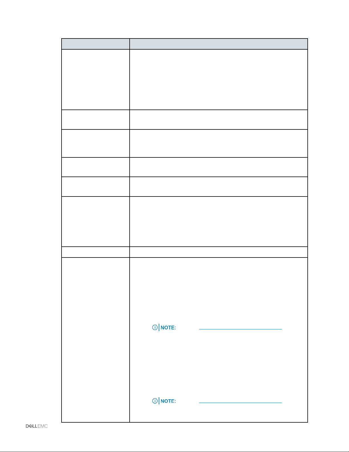
5 The following table shows recommended settings:
Edit option Field: recommended setting
General
Advanced
Security
Traffic shaping
VLAN
Teaming and failover
—
Name: the name chosen for the distributed port group
—
Port binding: Static Binding
—
Port allocation: Elastic
—
Number of ports: 8 (increases automatically as long as Elastic is
selected for port allocation)
—
Network resource pool: use default setting
—
Description: Add details about distributed port groups
—
Configure reset at disconnect: Enabled
—
Override port policies: use default setting
—
Promiscuous mode: Reject
—
MAC address changes: Reject
—
Forged transmit: Reject
—
Ingress traffic shaping: Disabled
—
Egress traffic shaping: Disabled
—
VLAN type: VLAN
—
VLAN ID: Refer to the Logical Configuration Survey
—
Load balancing: Route based on physical NIC load. The vMotion port
group only has one active uplink (associated with vNIC2 fabric A). The
other uplink should be in standby mode
—
Network failure detection: Link status only
—
Notify switches: Yes
—
Failback: Yes
Monitoring Netflow: default
Traffic filtering and
marking
—
Status: enable this option for vMotion NFS distributed port groups. All
other port groups should be disabled
—
vMotion Traffic Rule Enabled - use the + sign to make edits
—
Action tag
—
COS value checkbox is selected
—
Set CoS to 4
—
Set traffic direction to Ingress.
—
Type System Traffic and set Protocol/Traffic Type to vMotion
—
NFS Traffic Rule Enabled - use the + sign to make edits
—
Action tag
—
COS value checkbox is selected
—
Set CoS to 2
—
Set traffic direction to Ingress.
—
Type IP and set Protocol/Traffic Type to Any
See the VMware vSphere 6.x Release Notes for
information about ingress and egress parameters.
See the VMware vSphere 6.x Release Notes for
information about ingress and egress parameters.
Managing VMware VDS | 92
Page 93

Edit option Field: recommended setting
Miscellaneous Block all ports: No
Creating a distributed port group
You can use the VMware vSphere Web Client to create and add virtual and VMKernel distributed port
groups to an existing VMware VDS. After you create a distributed port group, you must configure the port
group.
Procedure
1 To launch the VMware vSphere Web Client from the VMware vCenter Server, open a browser
and type the following URL: https://<vCenterIP>:9443/vsphere-client.
You can also launch the VMware vSphere Web Client by selecting Start Menu > All
Programs > VMware > VMware vSphere Web Client.
The alternative launch method above does not apply to vSphere 6.5.
2 Log on to the VMware vSphere Web Client with the [email protected] user account
(Single Sign-On (SSO) account) or other administrative account with appropriate permissions.
3 On the VMware vSphere Web Client Home tab, under Inventories, click Networking.
4 Right-click DVSwitch01-A and select New Distribution Port Group.
5 From the New Distributed Port Group wizard, to create the distributed port group, perform the
following:
a Type the name of the distributed port group and click Next.
b Leave Port binding and Port allocation to the default settings Static binding and Elastic.
c Leave the Number of Ports to the default setting of eight.
d Set the VLAN type to VLAN and change the VLAN ID.
e Leave Customize default policies configuration unchecked.
f Click Next.
g Review and verify the settings for the new distributed port group and click Finish.
Virtual distributed port groups can be assigned to the VMs. VMKernel distributed port groups
require configuration.
What to do next
As an option, assign VMKernel distributed port groups to the VMware vSphere ESXi hosts.
Configuring a VMKernel interface
Configure a VMKernel (vMotion or NFS) interface using the Add and Manage Host wizard.
93 | Managing VMware VDS
Page 94

About this task
IPv4 addresses are supported on Vblock Systems and VxBlock Systems. IPv6 addresses are supported
on VxBlock Systems.
Before you begin
Create a VMkernel distributed port group.
IPv6 is not supported on vSphere 6.5.
Procedure
1 From the VMware vSphere Web Client Home tab, under Inventories, select Networking.
2 Right-click DVSwitch01-A and select Add and Manage Hosts.
3 From the Add and Manage Hosts wizard, perform the following:
a Select Manage host networking and select Next.
b Select Attach hosts.
c From the Select member hosts window, select the VMware vSphere ESXi host, and click
OK.
d Verify that the selected host(s) have been added to the list and click Next.
e From the Select network adapter tasks window, deselect Manage physical adapters and
verify that Manage VMKernel adapters is selected.
f Click Next.
g Select the VMware vSphere ESXi host and click New adapter.
h From the Add Networking window, verify that Select an existing Distributed Port Group is
selected and click Browse.
i Select VMKernel (vMotion or NFS) distributed port group and click OK.
j Click Next.
k For the vMotion distributed port group only, select vMotion traffic and click Next.
l For the NFS distributed port group only, verify that Enable services is unchecked and click
Next.
m Select Use static IPv4/IPv6 settings, apply IPv4 or IPv6 address/Subnet Mask, and click
Next.
Important: Dual IP stack is not supported.
n When the Analyze impact window appears, click Next.
o From the Ready to complete window, validate the settings and click Finish.
Managing VMware VDS | 94
Page 95

p Select the new VMKernel.
q Select Edit adapter.
r Select NIC settings.
s Verify that the MTU setting is set to 1500 (NFS MTU=9000).
t Click OK and Finish.
u Repeat steps g through s for each additional VMware vSphere ESXi host to create a new
network adapter.
v Click Next.
w Verify that the No Impact message appears and click Next.
x Review and verify the Summary results and click Finish.
Associating VMware vSphere ESXi hosts to an existing VMware VDS
Associating a new VMware vSphere ESXi host to an existing VMware VDS requires adding the VMNICs
to the VMware VDS uplinks. From the Add and Manage Hosts wizard, you can associate the VMware
vSphere ESXi hosts to the VMware VDS.
Before you begin
Verify which VMware VDS the VMware vSphere ESXi host will add.
Procedure
1 To launch the VMware vSphere Web Client from VMware vCenter Server, open a browser and
type the following URL: https://<vCenterIP>:9443/vsphere-client
You can also launch the VMware vSphere Web Client by selecting Start Menu > All
Programs > VMware > VMware vSphere Web Client.
The alternative launch method above does not apply to vSphere 6.5.
2 Log on to the VMware vSphere Web Client with the [email protected] user account
(SSO account) or other administrative account with appropriate permissions.
3 On the VMware vSphere Web Client Home tab, under Inventories, click Networking.
4 Right-click DVSwitch01-A and select Add and Manage Hosts.
5 From the Add and Manage Hosts wizard, perform the following:
a Select Add Hosts and click Next.
b Select New Hosts.
95 | Managing VMware VDS
Page 96

c From the Select new hosts window, select the VMware vSphere ESXi host to be added and
click OK.
You can modify multiple VMware vSphere ESXI hosts at a time using the Add and
Manage Hosts wizard.
The alternative launch method above does not apply to vSphere 6.5.
d Validate the selected host appears in the list and click Next.
e From the Select network adapter tasks window, deselect Manage VMKernel adapters.
f Verify that Manage physical adapters is selected and click Next.
g Select Uplink 1 and click OK.
h Select Uplink 2 and click OK.
i Click Next.
j Verify that the status message displays no impact and click Next.
6 Review the Summary results and click Finish.
Configuring jumbo frames on VMware VDS
Use this procedure to configure jumbo frames on an existing VMware vSphere Distributed Switch (VDS).
Procedure
1 Open a browser and type the following URL: https://<vCenterIP>:9443/vsphere-
client
You can also launch the VMware vSphere Web Client by selecting Start Menu > All
Programs > VMware > VMware vSphere Web Client.
The alternative launch method above does not apply to vSphere 6.5.
2 Log on to the VMware vSphere Web Client with the [email protected] user account
(VMware vSphere Single Sign-On (SSO) account) or other administrative account with
appropriate permissions.
3 On the VMware vSphere Web Client Home tab, under Inventories, click Networking.
4 Right-click DVSwitch01-A and select Edit Settings.
5 On the Properties tab, select Advanced.
6 Change the MTU value from 1500 to 9000.
7 Click OK.
Managing VMware VDS | 96
Page 97

Configuring jumbo frames on distributed port groups
Use this procedure to configure jumbo frames on the NFS distributed port group.
Procedure
1 Open a browser and type the following URL: https://<vCenterIP>:9443/vsphere-
client
You can also launch the VMware vSphere Web Client by selecting Start Menu > All
Programs > VMware > VMware vSphere Web Client.
The alternative launch method above does not apply to vSphere 6.5.
2 Log on to the VMware vSphere Web Client with the [email protected] user account
(VMware vSphere Single Sign-On (SSO) account) or other administrative account with
appropriate permissions.
3 On the VMware vSphere Web Client Home tab, under Inventories, select Hosts and Clusters.
4 Select the first host.
Each NFS distributed port group must be modified for each VMware vSphere ESXi
host.
5 Under Manage, select Networking, and then select VMKernel adapters.
6 From the table, select the adapter with the vcesys_esx_nfs listed under the network label.
7 Click the edit icon to select NIC settings and change the MTU value from 1500 to 9000.
8 Click OK.
9 Repeat this procedure for each VMware vSphere ESXi host as needed.
Modifying CoS settings
The CoS marking is leveraged as part of the standard configuration and configured with the Traffic
Filtering and marking policy on VMware VDS.
Procedure
1 Launch the VMware vSphere Web Client by selecting Start Menu > All Programs > VMware >
VMware vSphere Web Client or open a browser and type the following URL: https://
<vCenterIP>:9443/vsphere-client
2 Log on to the VMware vSphere Web Client with the [email protected] user account
(VMware SSO account) or other administrative account with appropriate permissions.
3 On the VMware vSphere Web Client Home tab, under Inventories, click Networking.
4 Expand the DVswitch01-A to view all port groups.
5 Right-click vcesys_esx_vmotion distributed port group and click Edit settings.
97 | Managing VMware VDS
Page 98

6 Select Traffic filtering and marking.
7 From the Status drop-down box, select Enable.
8 Select the green plus (+) icon to open the New Network Traffic Rule wizard, and perform the
following:
a For the Name, type: vMotionCOS.
b For Action, select Tag.
c Change the CoS value to 4.
d For VMware vSphere 6.x, change the Traffic direction to Ingress. The VMware vSphere 6.x
Release Notes contain information about ingress and egress parameters.
e Select the green plus (+) and select New System Traffic Qualifier.
f Verify that the type is set System traffic and the Protocol/Traffic type is set to vMotion.
g Click OK.
9 Right-click the vcesys_esx_nfs distributed port group, click Edit settings.
10 From the wizard, perform the following:
a For the Name, type: NFSCOS
b For Action, select Tag.
c Check Update CoS tag, and change value to 2.
d For VMware vSphere 6.x, change the Traffic direction to Ingress. The
Release Notes contain information about ingress and egress parameters.
e Select the green plus (+) and select New IP Qualifier.
f From the Protocol drop-down, select Any.
g Leave the Type as IP and click OK.
VMware vSphere 6.x
Decommissioning VMware VDS components
Decommissioning VMware VDS components requires deleting distributed port groups, disassociating the
VMware vSphere ESXi hosts, and remove the VMware VDS.
Managing VMware VDS | 98
Page 99

Deleting a distributed port group
Delete a distributed port group from an existing VMware VDS.
Before deleting a distributed port group, reassign all powered-on VMs to a different distributed
•
port group. If the VMs are powered off, delete the distributed port group.
If you delete a distributed port group with powered-on VMs and network adapter
numbers assigned to the distributed port group, the system returns an error.
Migrate the VMKernel ports from the VMware vSphere ESXi host attached to the VMware VDS.
•
Migrating VM distributed port group assignments to a different switch
If there are powered-on VMs on the distributed port group, migrate VM distributed port group assignments
to a different distributed or standard switch.
About this task
This procedure is not required if there are no powered-on VMs on the distributed port group. VMs
connected to the distributed port group can be powered-off to remove the distributed port group.
Use the VM migration wizard to migrate any port group types. However, use caution when migrating the
VMware vCenter Server VMs, because a disconnect can cause the loss of the VMware vCenter Server,
which could prevent the VM port group from migrating.
Use the VM migration wizard to migrate from a VMware vSphere Standard Switch to a VMware VDS, a
VMware VDS to a VMware vSphere Standard Switch, or a VMware VDS to a VMware VDS seamlessly.
Before you begin
Verify the powered-on VMs on all VMware vSphere ESXi hosts attached to an existing VMware VDS are
not assigned to any distributed port groups.
Verify there is an available distributed port group to which to migrate the powered-on VMs.
Create another switch with the following criteria:
If migrating to a different VMware VDS:
•
—
Attach at least one VMNIC as an uplink for a new distributed or standard switch.
—
Create the distributed port groups with the same name and VLAN ID as the existing switch.
If migrating to a standard switch:
•
—
Create a new standard switch and attach at least one VMNIC as an uplink for the standard
switch.
—
vNIC0 and vNIC1 connect to a different set of physical switches than vNIC2 and vNIC3. Do
not add vNIC2 and/or vNIC3 to vSwitch0, because it could cause the VMware vSphere ESXi
host to lose network connectivity if management traffic gets switched.
—
If no VMNICs are available, migrate one VMNIC from the VMware VDS. Keep the second
VMNIC on the Distributed Switch for VM traffic to continue to communicate
99 | Managing VMware VDS
Page 100

—
Create the VM port group with correct VLAN ID to the new standard switch.
Procedure
1 Open a browser and type the following URL: https://<vCenterIP>:9443/vsphere-
client You can also launch the VMware vSphere Web Client by selecting Start Menu > All
Programs > VMware > VMware vSphere Web Client. The alternative launch method above
does not apply to vSphere 6.5.
2 Log on to the VMware vSphere Web Client with the [email protected] user account
(VMware vSphere SSOaccount) or other administrative account with appropriate permissions.
3 On the VMware vSphere Web Client Home tab, under Inventories, click Networking.
4 Right-click DVswitch01-A and select Migrate VM to Another Network.
5 From the Migrate Virtual Machine Networking wizard, perform the following:
a Verify that Specific network is selected and click Browse.
b Select the Source network distributed port group or standard port group and click OK.
c Select Browse for the destination network.
d Select the distributed port group or port group where the VMs will be reassigned and click
Ok.
e Click Next.
f When the list of VMs appear, select the checkbox on each VM, and click Next.
g Validate that the source and destination is correct and click Finish. The selected VMs
distributed port groups migrate to a new distributed or standard switch.
Deleting the distributed port group from the VMware VDS
If there are no powered on VMs on the distributed port group, delete the distributed port group from the
existing VMware VDS.
Before you begin
Verify there is no port assignment connected to any of the distributed port group on any of the VMs.
Procedure
1 Launch the VMware vSphere Web Client by selecting Start Menu > All Programs > VMware >
VMware vSphere Web Client or open a browser and type the following URL: https://
<vCenterIP>:9443/vsphere-client
2 Log on to the VMware vSphere Web Client with the [email protected] user account
(VMware vSphere SSO account) or other administrative account with appropriate permissions.
3 On the VMware vSphere Web Client Home tab, under Inventories, click Networking.
4 Select the drop-down Array on DVswitch01-A to list the distributed port groups.
Managing VMware VDS | 100
 Loading...