

Page 1

Dell UltraSharp 27 4K PremierColor
Monitor—UP2720Q
User’s Guide
Model: UP 2720Q
Regulatory model : UP2720Qb
Page 2

Notes, cautions, and warnings
NOTE: A NOTE indicates important information that helps you make
better use of your computer.
CAUTION: A CAUTION indicates potential damage to hardware or loss
of data if instructions are not followed.
WARNING: A WARNING indicates a potential for property damage,
personal injury, or death.
Copyright © 2019 - 2020 Del l Inc. All rights reserved. This product is protected by U.S. and
international copyright and intellectual property laws. Dell™ and the Dell logo are trademarks of Dell Inc.
in the United States and/or other jurisdictions. Thunderbolt™ and the Thunderbolt™ logo are trademarks
of Intel Corporation in the U.S. and/or other countries. All other marks and names mentioned herein may
be trademarks of their respective companies.
2020- 01
Rev. A01
Page 3

Contents
About Your Monitor. . . . . . . . . . . . . . . . . . . . . . . . . . 6
Package Contents . . . . . . . . . . . . . . . . . . . . . . . . . . . . . . . 6
Product Features . . . . . . . . . . . . . . . . . . . . . . . . . . . . . . . . 9
Identifying Parts and Controls . . . . . . . . . . . . . . . . . . . . . 10
Front View. . . . . . . . . . . . . . . . . . . . . . . . . . . . . . . . . . . . . . . . . . . . 10
Back View . . . . . . . . . . . . . . . . . . . . . . . . . . . . . . . . . . . . . . . . . . . . 11
Bottom View . . . . . . . . . . . . . . . . . . . . . . . . . . . . . . . . . . . . . . . . . . 12
Monitor Specifications. . . . . . . . . . . . . . . . . . . . . . . . . . . 14
Flat Panel Specifications . . . . . . . . . . . . . . . . . . . . . . . . . . . . . . . . 14
Resolution Specifications . . . . . . . . . . . . . . . . . . . . . . . . . . . . . . . .15
Supported Video Modes . . . . . . . . . . . . . . . . . . . . . . . . . . . . . . . . . 16
Preset Display Modes . . . . . . . . . . . . . . . . . . . . . . . . . . . . . . . . . . .16
Multi-Stream Transport (MST) Modes. . . . . . . . . . . . . . . . . . . . . . 17
Electrical Specifications . . . . . . . . . . . . . . . . . . . . . . . . . . . . . . . . . 17
Physical Characteristics . . . . . . . . . . . . . . . . . . . . . . . . . . . . . . . . . 18
Physical Characteristics (Continued). . . . . . . . . . . . . . . . . . . . . . .19
Power Management Modes . . . . . . . . . . . . . . . . . . . . . . . . . . . . . 20
Pin Assignments . . . . . . . . . . . . . . . . . . . . . . . . . . . . . . . . . . . . . . 22
Plug and Play Capability. . . . . . . . . . . . . . . . . . . . . . . . . . 24
Universal Serial Bus (USB) Interface . . . . . . . . . . . . . . . . 24
USB Downstream Connector . . . . . . . . . . . . . . . . . . . . . . . . . . . . 25
Thunderbolt™ 3 Connector. . . . . . . . . . . . . . . . . . . . . . . . . . . . . . 26
USB Ports . . . . . . . . . . . . . . . . . . . . . . . . . . . . . . . . . . . . . . . . . . . 26
LCD Monitor Quality and Pixel Policy. . . . . . . . . . . . . . . . 27
Maintenance Guidelines . . . . . . . . . . . . . . . . . . . . . . . . . . 27
Cleaning Your Monitor . . . . . . . . . . . . . . . . . . . . . . . . . . . . . . . . . .27
│ 3
Page 4

Setting Up the Monitor . . . . . . . . . . . . . . . . . . . . . 28
Attaching the Stand . . . . . . . . . . . . . . . . . . . . . . . . . . . . . 28
Attaching the Monitor Hood . . . . . . . . . . . . . . . . . . . . . . 31
Connecting Your Monitor . . . . . . . . . . . . . . . . . . . . . . . . . 32
Connecting the HDMI cable . . . . . . . . . . . . . . . . . . . . . . . . . . . . . . 33
Connecting the DisplayPort (DP to DP) cable. . . . . . . . . . . . . . . . 34
Connecting the Thunderbolt™ 3 Active cable . . . . . . . . . . . . . . . . 34
Connecting the monitor for Thunderbolt™ Multi-Stream
Transport (MST) function . . . . . . . . . . . . . . . . . . . . . . . . . . . . . . . 35
Connecting the USB Type-C to Type-A cable . . . . . . . . . . . . . . . . 36
Organizing Your Cables . . . . . . . . . . . . . . . . . . . . . . . . . . 37
Removing the Monitor Stand . . . . . . . . . . . . . . . . . . . . . . 38
Wall Mounting (Optional). . . . . . . . . . . . . . . . . . . . . . . . . 39
Operating the Monitor . . . . . . . . . . . . . . . . . . . . . . 40
Power On the Monitor . . . . . . . . . . . . . . . . . . . . . . . . . . . 40
Using the Front Panel Controls . . . . . . . . . . . . . . . . . . . . 40
Front Panel Button . . . . . . . . . . . . . . . . . . . . . . . . . . . . . . . . . . . . 42
Using the On-Screen Display (OSD) Menu . . . . . . . . . . . 43
Accessing the Menu System . . . . . . . . . . . . . . . . . . . . . . . . . . . . . 43
OSD Warning Messages. . . . . . . . . . . . . . . . . . . . . . . . . . . . . . . . . 61
Setting the Maximum Resolution. . . . . . . . . . . . . . . . . . . 64
Performing Color Calibration . . . . . . . . . . . . . . . . . . . . . . 65
Using the OSD menu . . . . . . . . . . . . . . . . . . . . . . . . . . . . . . . . . . . 65
Using the Shortcut Key with video signal . . . . . . . . . . . . . . . . . . . 66
Using the Shortcut Key without video signal. . . . . . . . . . . . . . . . . 67
Stopping the Calibration Process . . . . . . . . . . . . . . . . . . 68
Performing Color Validation. . . . . . . . . . . . . . . . . . . . . . . 69
Using the OSD menu . . . . . . . . . . . . . . . . . . . . . . . . . . . . . . . . . . . 69
Using the shortcut key without video signal . . . . . . . . . . . . . . . . . 70
Stopping the Validation Process . . . . . . . . . . . . . . . . . . . 71
4 │
Page 5

Using the Tilt, Swivel, and Vertical Extension . . . . . . . . . 72
Tilt, Swivel . . . . . . . . . . . . . . . . . . . . . . . . . . . . . . . . . . . . . . . . . . .72
Vertical Extension . . . . . . . . . . . . . . . . . . . . . . . . . . . . . . . . . . . . . .73
Rotating the Monitor . . . . . . . . . . . . . . . . . . . . . . . . . . . . . . . . . . .73
Troubleshooting . . . . . . . . . . . . . . . . . . . . . . . . . . . 75
Sel f-Test. . . . . . . . . . . . . . . . . . . . . . . . . . . . . . . . . . . . . . 75
Built-in Diagnostics . . . . . . . . . . . . . . . . . . . . . . . . . . . . . 76
Always On USB Type-C (Thunderbolt™) Charging . . . . . 77
Common Problems . . . . . . . . . . . . . . . . . . . . . . . . . . . . . . 78
Product Specific Problems . . . . . . . . . . . . . . . . . . . . . . . 81
Universal Serial Bus (USB) Specific Problems . . . . . . . . 83
Appendix . . . . . . . . . . . . . . . . . . . . . . . . . . . . . . . . . 85
FCC Notices (U.S. Only) and Other Regulatory
Information. . . . . . . . . . . . . . . . . . . . . . . . . . . . . . . . . . . . 85
Contact Dell . . . . . . . . . . . . . . . . . . . . . . . . . . . . . . . . . . . 85
Video and USB Support over USB-C . . . . . . . . . . . . . . . . 86
Purchasing a Thunderbolt™ 3 Passive Cable. . . . . . . . . . 87
│ 5
Page 6
About Your Monitor
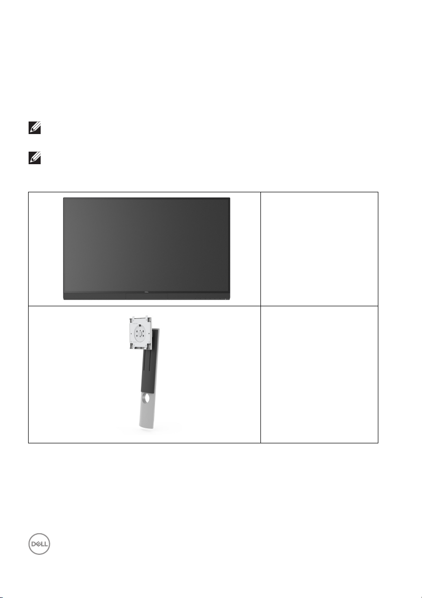
Package Contents
Your monitor ships with the components shown below. Ensure that you have
received all the components and
NOTE: Some items may be optional and may not ship with your monitor.
Some features or media may not be available in certain countries.
NOTE: To set up with any other stand, please refer to the respective
stand setup guide for setup instructions.
Contact Dell if something is missing.
Monitor
Stand Riser
6 │ About Your Monitor
Page 7
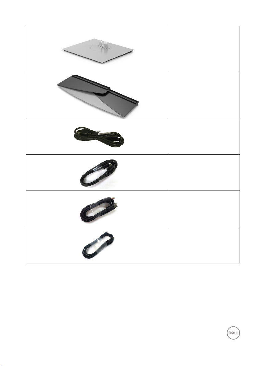
Stand Base
Monitor Hood
Power Cable (Varies by
Country)
HDMI Cable
DP Cable (DP to DP)
Thunderbol t™ 3 (USB
Type-C) Active Cable
About Your Monitor │ 7
Page 8
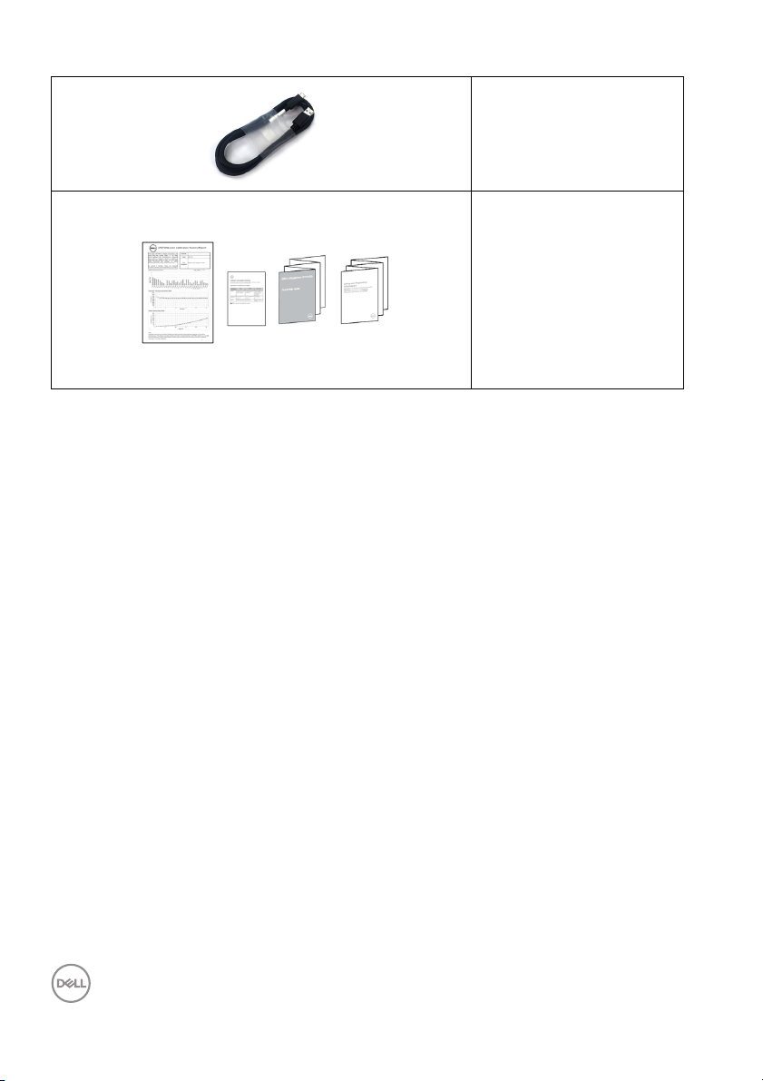
U S B Ty p e - C t o Ty p e - A
Cable
•Factory Calibration
Report
•Calibration and
Validation Techsheet
•Quick Setup Guide
• Safety, Environmental,
and Regulatory
Information
8 │ About Your Monitor
Page 9

Product Features
The Dell UP2720Q flat panel display has an active matrix, Thin-Film Transistor
(TFT), Liquid Crystal Display (LCD) and LED backlight. The monitor features
include:
• 68.47 cm (27 in.) viewable area display (measured diagonall y).
3840 x 2160 (16:9) resolution, plus full-screen support for lower resolutions.
• Wide viewing angle to allow viewing from a sitting or standing position.
• Color gamut of CIE1931 Adobe 100% and CIE1976 DCI-P3 98% with an
average Delta E
• Supports HDMI, DP, and Thunderbolt™ 3 sources.
• HDMI, DP, and Thunderbolt™ 3 connection supports 10-bit color at 60 Hz.
• Single Thunderbolt™ 3 to suppl y power (Up to 90 W) to a compatible
notebook while receiving video & data signal.
• Built-in Color Calibration functionality.
• Multi-Stream Transport (MST) capability via Thunderbolt™ 3 connection.
• Tilt, swivel, pivot, and vertical extension adjustment capabilities.
• Ultra-thin bezel minimizes the bezel gap in multi-monitor usage, enabling
easier setup with an elegant viewing experience.
• Removable stand and Video Electronics Standards Association (VESA™)
100 mm mounting holes for flexible mounting solutions.
• Plug and play capability if supported by your system.
• On-Screen Display (OSD) adjustments for ease of set-up and screen
optimization.
• Supports Menu, Power buttons and Color lock via OSD.
• Security lock slot.
• 0.5 W standby power when in the sleep mode.
• Supports Picture by Picture (PBP) Select mode.
• Optimize eye comfort with a flicker-free screen.
< 2.
About Your Monitor │ 9
Page 10
Identifying Parts and Controls
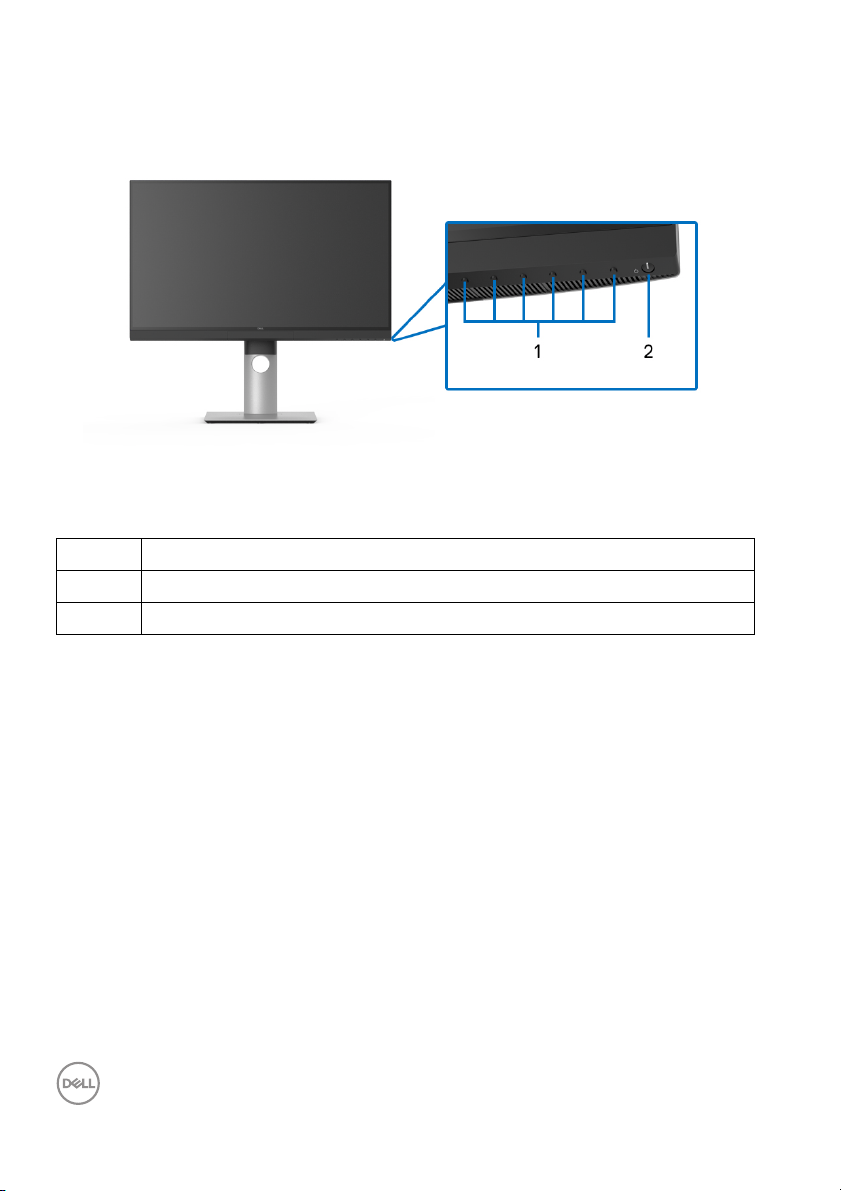
Front View
Front panel controls
Label Description
1 Function buttons (For more information, see Operating the Monitor)
2 Power On/Off button (with LED indicator)
10 │ About Your Monitor
Page 11
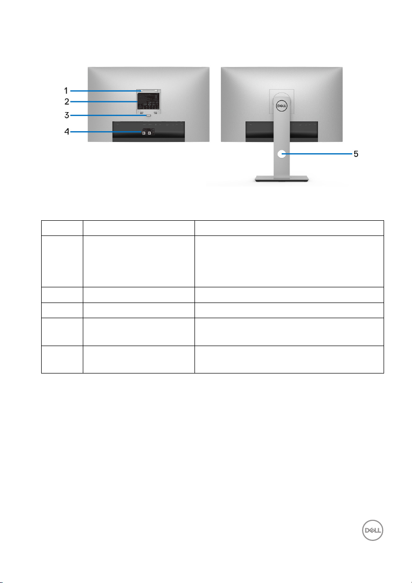
Back View
Back view without and with monitor stand
Label Description Use
1 VESA mounting holes
(100 mm x 100 mmbehind attached VESA
Cover)
2 Regulatory label Lists the regulatory approvals.
3 Stand release button Releases stand from monitor.
4 Barcode, serial number,
and Service Tag label
5 Cable management hole Use to organize cables by placing them
Wall mount monitor using VESA-compatible
wall mount kit (100 mm x 100 mm.)
Refer to this label if you need to contact
Del l for technical support.
through the hole.
About Your Monitor │ 11
Page 12
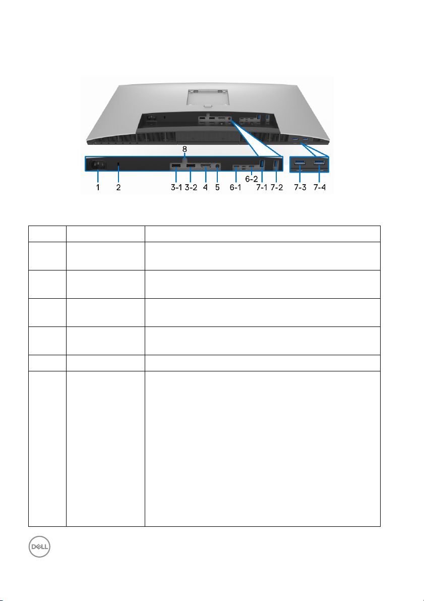
Bottom View
Bottom view without monitor stand
Label Description Use
1 AC power
connector
2 Security lock
slot
3
HDMI port
(1, 2)
connector
4 DisplayPort in
connector
5 Audio-Line out Connect your speakers.*
6-1 Thunderbol t™ 3
Upstream
(USB Type-C)
port
Connect the power cable (shipped with your monitor).
Secures monitor with security lock (security lock not
included).
Connect your computer with HDMI cable.
Connect your computer with DP cable.
Connect the Thunderbolt™ 3 Active cable that came
with your monitor to the computer or mobile device.
This port supports USB Power Delivery (up to 90 W),
Data, and DisplayPort video signal.
The Thunderbol t™ 3 port supports Al ternate Mode
DP1.4 with a maximum resolution of 3840 x 2160 at
60 Hz, PD 20 V/4.5 A, 15 V/3 A , 9 V/3 A, and 5 V/3 A.
Thunderbol t™ 3 supports MST (Mul ti-Stream
Transport) capable monitor. To enable MST, refer to
instruction on section “
Thunderbol t™ Multi-Stream Transport (MST)
function”.
Connecting the monitor for
12 │ About Your Monitor
Page 13

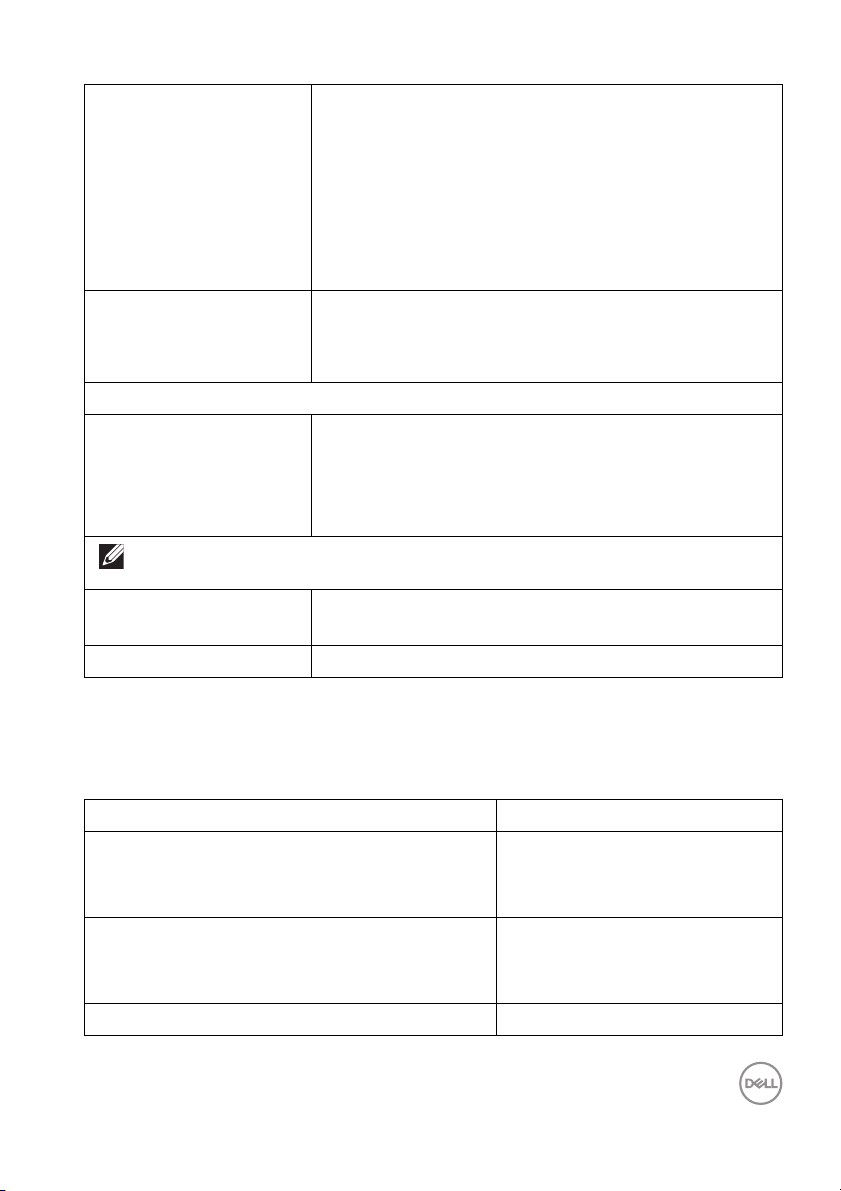
6-2 Thunderbol t™ 3
Downstream
(USB Type-C)
port
7
USB 3.2 Gen2
(1, 2,)
7-3 USB 3.2 Gen1
7-4 USB 3.2 Gen1
downstream
port
downstream
port with Power
Charging
downstream
port
8 Stand lock
feature
NOTE: Thunderbol t™ 3 is not supported on versions
of Windows prior to Windows 10.
Connect the Thunderbol t™ 3 Active cable that came
with your monitor to the computer, mobile devices, a
second monitor, or other Thunderbolt™ devices. This
port supports USB Power Delivery (up to 15 W,
PD 5 V/3 A), Data, and DisplayPort video signal.
Thunderbol t™ 3 supports MST (Multi-Stream
Transport) capable monitor. To enable MST, refer to
instruction on section “
Thunderbol t™ Mul ti-Stream Transport (MST)
function”.
NOTE: For Notebooks and other devices that require
more than 15 W of power, it is recommended to
connect to another power source to power or charge
your device.
NOTE: Thunderbol t™ 3 is not supported on versions
of Windows prior to Windows 10.
Connect your USB device. You can only use this
connector after you have connected the USB cable to
the computer.**
Connect to charge your device.
Connect your USB device. You can only use this
connector after you have connected the USB cable to
the computer.**
To lock the stand to the monitor using a M3 x 6 mm
screw (screw not included).
Connecting the monitor for
* Headphone usage is not supported for the audio line out connector.
** To avoid signal interference, when a wireless USB device has been connected to
a USB downstream port, it is NOT recommended to connect any other USB
devices to the adjacent port(s).
About Your Monitor │ 13
Page 14

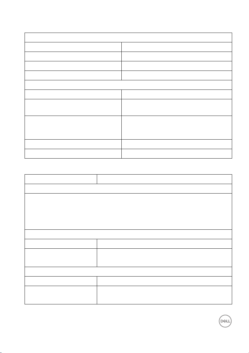
Monitor Specifications
Flat Panel Specifications
Model UP2720Q
Screen type Active matrix - TFT LCD
Panel technology In-Plane Switching Type
Aspect ratio 16:9
Viewable image
Diagonal
Horizontal, Active Area
Vertica l, Active Area
Area
Pixel pitch 0.1554 mm x 0.1554 mm
Pixel per inch 163
Viewing angle 178° (vertical) typical
Luminance output 250 cd/m² (typical)
Contrast ratio 1300 to 1 (typical)
Faceplate coating Antiglare with hard-coating 3H
Backlight White LED edgelight system
Response time • 6 ms gray to gray in Fa
Color depth 1.07 bill ion colors (real 10 Bit)
Color gamut CIE1931 Adobe 100%
Calibration accuracy Del ta E <
684.7 mm (27 in.)
596.74 mm (23.49 in.)
335.66 mm (13.21 in.)
200301 mm
178° (horizontal) typical
• 8 ms gray to gray in Norma
CIE1976 DCI-P3 98%
CIE1976 BT.2020 80%
NOTE: On
DCI-P3 98%.
2
(310.47 in.2)
st Mode
2 (average)
ly for CIE1931 Adobe 100% and CIE1976
l Mode
14 │ About Your Monitor
Page 15
Connectivity • 1 x DP 1.4 (HDCP 2.2)
• 2 x HDMI 2.0 (HDCP 2.2)
• 1 x Thunderbol t™ 3 Upstream port (DP1.4)
• 1 x Thunderbol t™ 3 Downstream port (DP1.4)
•2 x USB 3.2 Gen2 Downstream port
• 2 x USB 3.2 Gen1 Downstream port (1 x BC1.2
charging capability at 2 A (max))
Border width (edge of
monitor to active area)
7.6 mm (Top)
7.6 mm (Left/Right)
27.1 mm (Bottom)
Adjustability
Height adjustable stand
Ti l t
Swivel
Pivot
NOTE: Do not mount inverse (180°) landscape orientation as it may damage the
monitor.
Dell Display Manager
130 mm
-5° to 21°
-45° to 45°
-90° to 90°
Yes
(DDM) Compatibility
Security Security lock slot (cable lock sold separately)
Resolution Specifications
Model UP2720Q
Horizontal scan range
15 kHz to 135 kHz (automatic)
(HDMI & DP & Thunderbol t™ 3 alternate
mode)
Vertica l scan range
23 Hz to 86 Hz (automatic)
(HDMI & DP & Thunderbol t™ 3 alternate
mode)
Maximum preset resolution 3840 x 2160 at 60 Hz
About Your Monitor │ 15
Page 16

Supported Video Modes
Model UP2720Q
Video display capabilities (HDMI playback) 480p, 576p, 720p, 1080i, 1080p,
QHD, UHD (Interlacing mode is
not supported under PBP mode)
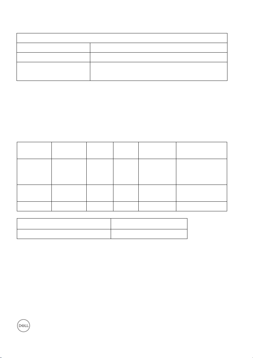
Preset Display Modes
Display Mode Horizontal
Frequency
(kHz)
VESA, 640 x 480 31.5 59.9 25.2 -/-
VESA, 640 x 480 37.5 75.0 31.5 -/-
VESA, 720 x 400 31.5 70.1 28.3 -/+
VESA, 800 x 600 37.9 60.3 40.0 +/+
VESA, 800 x 600 46.9 75.0 49.5 +/+
VESA, 1024 x 768 48.4 60.0 65.0 -/-
VESA, 1024 x 768 60.0 75.0 78.8 +/+
VESA, 1152 x 864 67.5 75.0 108.0 +/+
VESA, 1280 x 1024 64.0 60.0 108.0 +/+
VESA, 1280 x 1024 80.0 75.0 135.0 +/+
VESA, 1600 x 1200 75.0 60.0 162.0 +/+
VESA, 1920 x 1080 67.5 60.0 148.5 +/+
VESA, 2048 x 1280 - R 78.9 59.9 174.3 +/-
VESA, 2048 x 1440 - R 88.8 60.0 241.5 +/-
VESA, 3840 x 2160* 133.3 60.0 533.3 +/-
VESA, 3840 x 2160** 135 60.0 594 +/-
2560 x 1440 88.787 59.951 241.55 +/-
2048 x 1080 27.0 24.0 74.25 +/-
2048 x 1080 54.0 48.0 148.5 +/-
Vertical
Frequency
(Hz)
Pixel
Clock
(MHz)
Sync
Pol arity
(Horizontal
/Vertical)
16 │ About Your Monitor
Page 17
* Requires a graphics card that supports DP.
** Requires a graphics card that supports HDMI 2.0.
Mul ti-Stream Transport (MST) Modes
MST Source
Monitor
3840 x 2160
at 60 Hz
NOTE: Use the cables that came with your monitor for Thunderbolt™
Multi-Stream Transport (MST) connection. See
monitor for Thunderbolt™ Mul ti-Stream Transport (MST) function for
connection details.
Electrical Specifications
Model UP2720Q
Video input signals HDMI 2.0*/DP 1.4, 600 mV for each differential line,
AC input vo l tage/
frequency/current
Inrush current • 120 V: 40 A (Max.) at 0 °C (cold start)
* Not Support HDMI 2.0 optional specification, include HDMI Ethernet Channel
(HEC), Audio Return Channel (ARC), standard for 3D format and resolutions, and
standard for 4K digital cinema resolution.
Maximum number of external monitor can be supported
3840 x 2160 at 60 Hz
1
Connecting the
100 ohm input impedance per differential pair.
100 VAC to 240 VAC / 50 Hz or 60 Hz + 3 Hz /
2.8 A (typical)
• 240 V: 80 A (Max.) at 0 °C (cold start)
About Your Monitor │ 17
Page 18

Physical Characteristics
Model UP2720Q
Connector Type
Signal cable type • Digital: HDMI, 19 pins
NOTE: Del l monitors are designed to work optimally with the video cables that
are shipped with your monitor. As Del l does not have control over the different
cable suppliers in the market, the type of material, connector and process used to
manufacture these cables, Del l does not guarantee video performance on cables
that are not shipped with your Dell monitor.
Dimensions (with stand)
Height (extended) 563.4 mm (22.18 in.)
Height (compressed) 433.4 mm (17.06 in.)
Width 611.9 mm (24.09 in.)
Depth 212.0 mm (8.35 in.)
Dimensions (without stand)
Height 376.8 mm (14.83 in.)
Width 611.9 mm (24.09 in.)
Depth 51.0 mm (2.01 in.)
•1 x DP 1.4
•2 x HDMI 2.0
• 1 x Thunderbol t™ 3 Upstream (DP1.4)
• 1 x Thunderbol t™ 3 Downstream
(DP1.4)
• 2 x USB 3.2 Gen2 Downstream ports
• 2 x USB 3.2 Gen1 Downstream ports
(1 x BC1.2 charging capability at 2 A
(max))
• Digital: DisplayPort, 20 pins
• Digital: Thunderbol t™ 3, 24 pins
• Universal Serial Bus: USB Type-C to
Ty p e- A
18 │ About Your Monitor
Page 19
Physical Characteristics (Continued)
Stand dimensions
Height (extended) 456.3 mm (17.96 in.)
Height (compressed) 408.9 mm (16.10 in.)
Width 260.0 mm (10.24 in.)
Depth 212.0 mm (8.35 in.)
Weight
Weight with packaging 14.14 kg (31.17 lb)
Weight with stand assembly and
cables
Weight without stand assembl y
(For wall mount or VESA mount
considerations - no cables)
Weight of stand assembly 3.64 kg (8.02 lb)
Front frame gloss 2-4
Environmental Characteristics
Model UP2720Q
Compliant Standards
• RoHS-compliant
• TCO certified displays
• BFR/PVC-free (Halogen-free) excluding external cables
• Arsenic-free glass and Mercury-free for the panel only
Te m p er at u r e
Operating 0 °C to 40 °C (32 °F to 104 °F)
Non-operating • Storage: -20 °C to 60 °C (-4 °F to 140 °F)
• Shipping: -20 °C to 60 °C (-4 °F to 140 °F)
Humidity
Operating 10% to 90% (non-condensing)
Non-operating • Storage: 10% to 90% (non-condensing)
• Shipping: 10% to 90% (non-condensing)
9.71 kg (21.41 l b)
5.55 kg (12.24 lb)
About Your Monitor │ 19
Page 20
Environmental Characteristics (Continued)
Altitude
Operating 3,048 m (10,000 ft) (maximum)
Non-operating 12,192 m (40,000 ft) (maximum)
Thermal dissipation • 784.76 BTU/hour (maximum)
• 150.13 BTU/hour (typical)
Power Management Modes
If you have VESA's DPM™ compliance display card or software installed in your PC,
the monitor can automatically reduce its power consumption when not in use. This
is referred to as Power Save Mode*. If the computer detects input from the
keyboard, mouse, or other input devices, the monitor automatically resumes
functioning. The following table shows the power consumption and signaling of this
automatic power saving feature.
VESA
Modes
Normal
operation
Horizontal
Sync
Vertical
Sync
Video Power
Indicator
Consumption
Active Active Active White 230 W
(maximum)**
Power
44 W (typical)
Active-off
mode
Inactive Inactive Blanked White
(blinking)
Less than 0.5 W
Switch off - - - Off Less than 0.3 W
Power Consumption P
on
38 W
Total Energy Consumption (TEC) 130.74 kWh
* Zero power consumption in OFF mode can only be achieved by disconnecting the
main cable from the monitor.
** Maximum power consumption with max luminance, and USB active.
This document is informational only and reflects laboratory performance. Your
product may perform differently, depending on the software, components and
peripherals you ordered and shall have no obligation to update such information.
Accordingly, the customer should not rely upon this information in making decisions
about electrical tolerances or otherwise. No warranty as to accuracy or
completeness is expressed or implied.
20 │ About Your Monitor
Page 21
NOTE:
Pon: Power consumption of On Mode measured with reference to
Energy Star test method.
TEC: Total energy consumption in kWh measured with reference to
Energy Star test method.
The OSD functions only in the normal operation mode. When any button is pressed
in the Active-off mode, the following message will be displayed:
Activate the computer and the monitor to gain access to the OSD.
NOTE: The message may be slightly different according to the
connected input signal.
About Your Monitor │ 21
Page 22
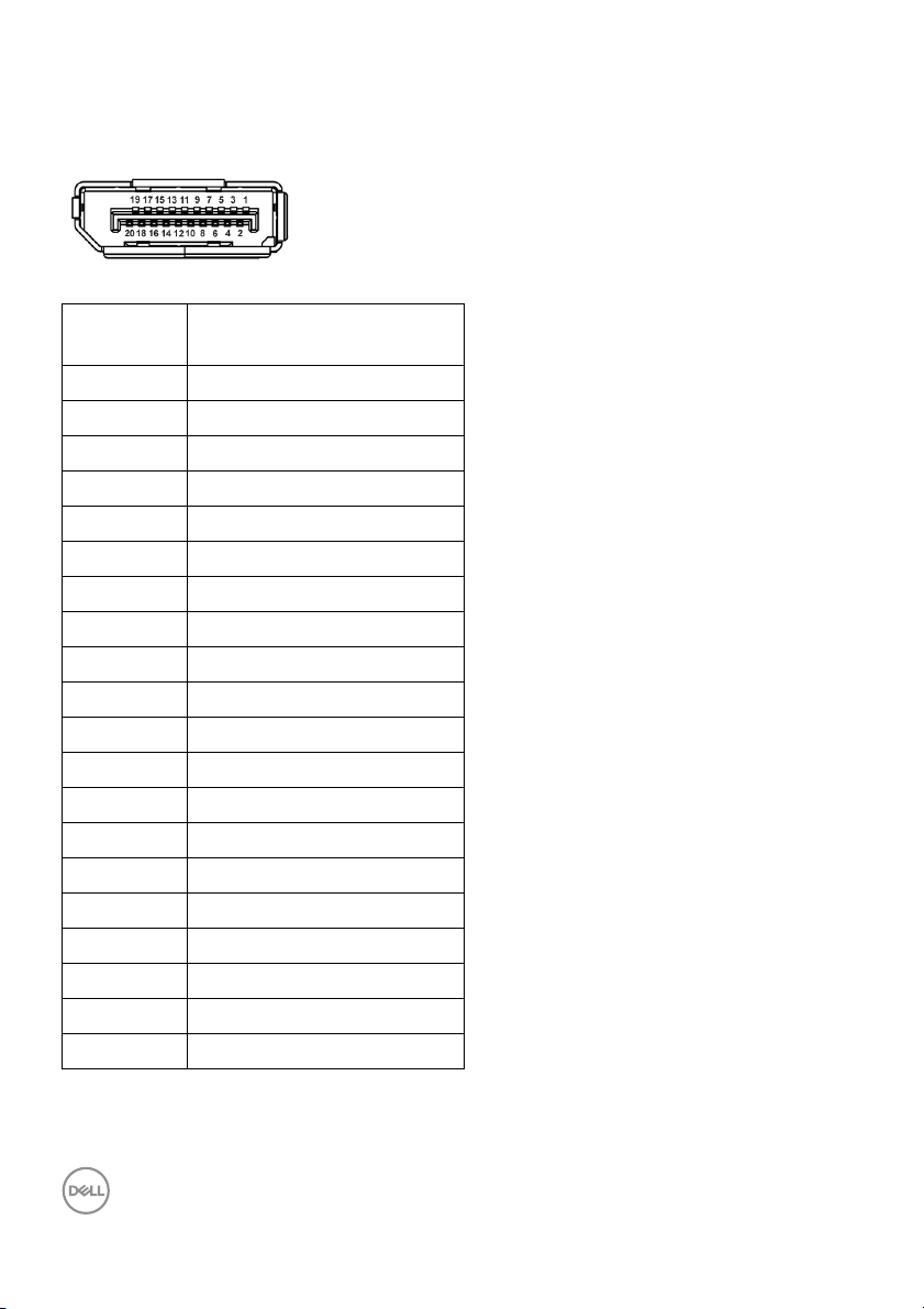
Pin Assignments
DisplayPort Connector
Pin
Number
1 ML3 (n)
2 GND
3 ML3 (p)
4 ML2 (n)
5 GND
6 ML2 (p)
7 ML1 (n)
8 GND
9 ML1 (p)
10 ML0 (n)
11 GND
12 ML0 (p)
13 GND
14 GND
15 AUX (p)
16 GND
17 AUX (n)
18 Hot Plug Detect
19 Re-PWR
20 +3.3 V DP_PWR
20-pin Side of the
Connected Signal Cable
22 │ About Your Monitor
Page 23
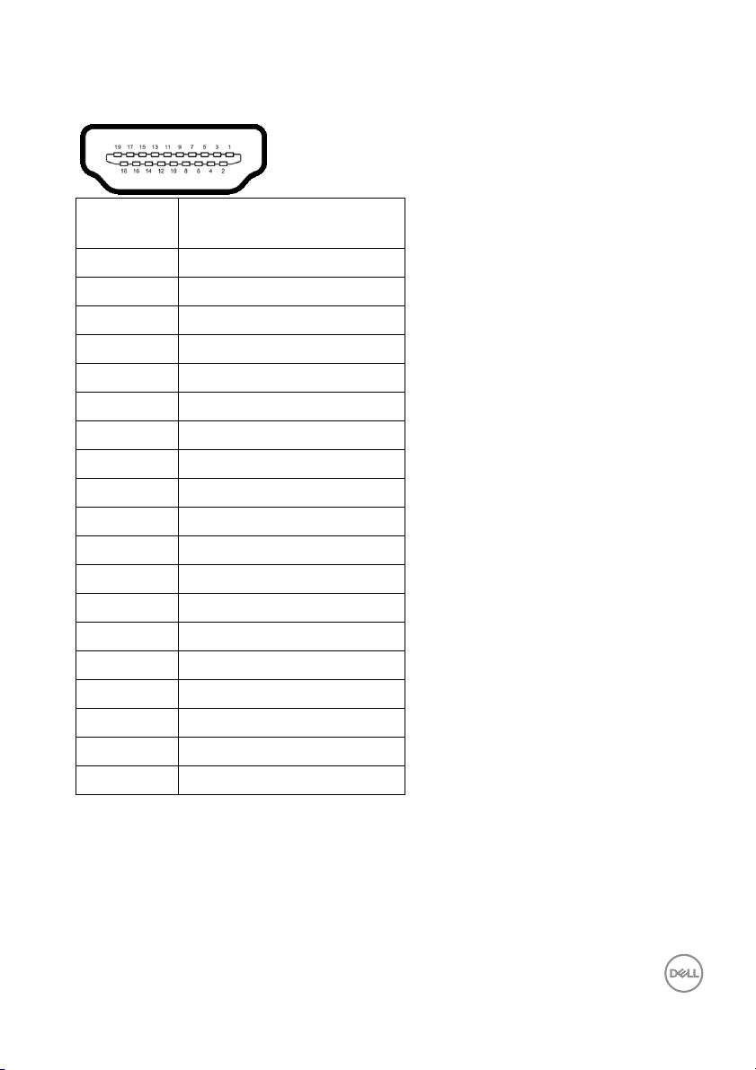
HDMI Connector
Pin
Number
1 TMDS DATA 2+
2 TMDS DATA 2 SHIELD
3 TMDS DATA 2-
4 TMDS DATA 1+
5 TMDS DATA 1 SHIELD
6 TMDS DATA 1-
7 TMDS DATA 0+
8 TMDS DATA 0 SHIELD
9 TMDS DATA 0-
10 TMDS CLOCK+
11 TMDS CLOCK SHIELD
12 TMDS CLOCK-
13 CEC
14 Reserved (N.C. on device)
15 DDC CLOCK (SCL)
16 DDC DATA (SDA)
17 DDC/CEC Ground
18 +5 V POWER
19 HOT PLUG DETECT
19-pin Side of the
Connected Signal Cable
About Your Monitor │ 23
Page 24
Plug and Play Capability
You can install the monitor in any Plug and Play-compatible system. The monitor
automatically provides the computer system with its Extended Display Identification
Data (EDID) using Display Data Channel (DDC) protocols so the system can
configure itself and optimize the monitor settings. Most monitor installations are
automatic; you can select different settings if desired. For more information about
changing the monitor settings, see
Operating the Monitor.
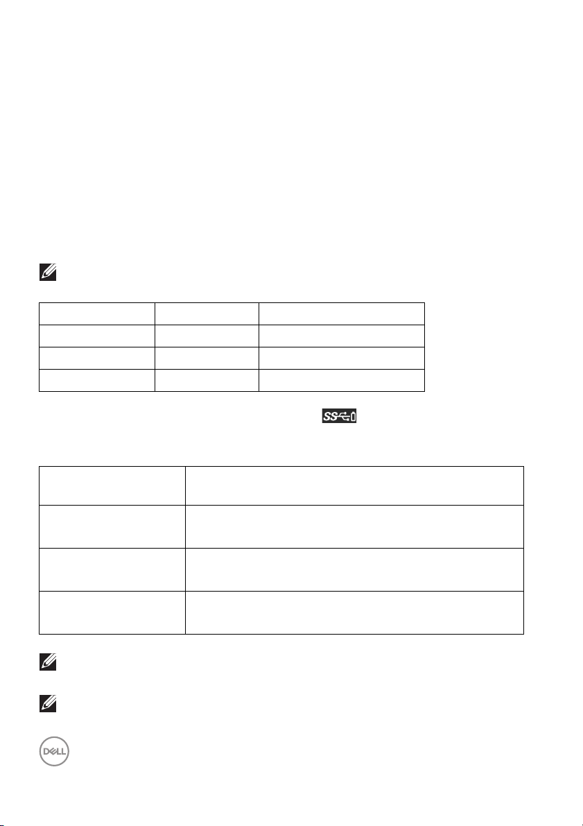
Universal Serial Bus (USB) Interface
This section gives you information about the USB ports that are available on the
monitor.
NOTE: This monitor is Super-Speed USB 3.2 compatible.
Transfer Speed Data Rate Power Consumption*
Super-speed 10 Gbps 4.5 W (Max, each port)
High speed 480 Mbps 4.5 W (Max, each port)
Full speed 12 Mbps 4.5 W (Max, each port)
* Up to 2A on USB downstream port (port with battery icon) with BC1.2
compliance devices or normal USB devices.
Thunderbol t™ 3/
USB Type-C
Video DP1.2 (Passive cable)
DP1.4 (Active cable)
Data USB 2.0
USB 3.2 (Active, Thunderbol t™ 3 onl y)
Power Delivery (PD) Thunderbolt™ 3 Upstream port: Up to 90 W (typical)
Thunderbol t™ 3 Downstream port: Up to 15 W (typical)
NOTE: USB Type-C video requires a Type-C Alternate Mode capability
computer.
NOTE: To support USB Type-C Alternate Mode, please ensure the
Source computer has Alternate Mode capability.
24 │ About Your Monitor
Description
Page 25

USB Downstream Connector
Pin Number 9-pin Side of the Connector
1 VCC
2 D-
3 D+
4 GND
5 SSRX-
6 SSRX+
7 GND
8 SSTX-
9 SSTX+
About Your Monitor │ 25
Page 26
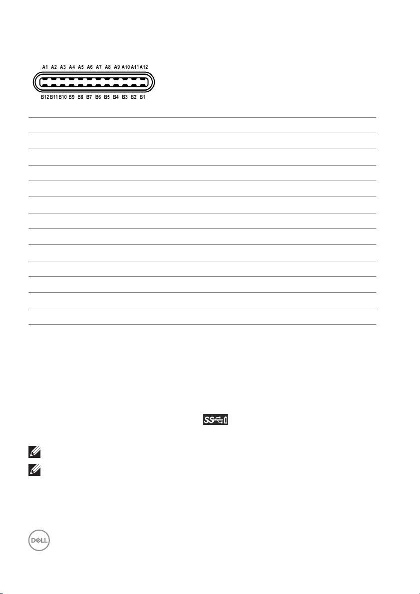
Thunderbol t™ 3 Connector
Pin Number Signal Name Pin Number Signal Name
A1 GND B1 Cable Detection
A2 TX1+ B2 TX2+
A3 TX1- B3 TX2-
A4 VBUS B4 VBUS
A5 CC1 B5 CC2
A6 D+ B6 D+
A7 D- B7 D-
A8 SBU1 B8 SBU2
A9 VBUS B9 VBUS
A10 RX2- B10 RX1-
A11 RX2+ B11 RX1+
A12 GND B12 GND
USB Ports
• 1 x Thunderbol t™ 3 downstream (USB Type-C compatible) - bottom
• 1 x Thunderbol t™ 3 upstream (USB Type-C compatible) - bottom
• 2 x USB 3.2 Gen2 downstream - bottom
• 2 x USB 3.2 Gen1 downstream - bottom
• Power Charging Port- the port with battery icon; supports fast current
charging capability if the device is BC1.2 compatible.
NOTE: USB 3.2 functionality requires a USB 3.2-capable computer.
NOTE: The monitor's USB interface works only when the monitor is On
or in the power save mode. If you turn Off the monitor and then turn it
On, the attached peripherals may take a few seconds to resume normal
functionality.
26 │ About Your Monitor
Page 27

LCD Monitor Quality and Pixel Policy
During the LCD Monitor manufacturing process, it is not uncommon for one or more
pixels to become fixed in an unchanging state which are hard to see and do not
affect the display quality or usability. For more information on Dell Monitor Quality
and Pixel Policy, see Dell Support site at:
monitors.
http://www.dell.com/support/
Maintenance Guidelines
Cleaning Your Monitor
CAUTION: Read and fol low the Safety Instructions before cleaning the
monitor.
WARNING: Before cleaning the monitor, unplug the monitor power
cable from the electrical outlet.
For best practices, follow the instructions in the list below while unpacking, cleaning,
or handling your monitor:
• To clean your anti-static screen, lightly dampen a soft, clean cloth with water.
If possible, use a special screen-cleaning tissue or solution suitable for the
anti-static coating. Do not use benzene, thinner, ammonia, abrasive cleaners,
or compressed air.
• Use a lightl y-dampened, warm cloth to clean the monitor. Avoid using
detergent of any kind as some detergents leave a milky film on the monitor.
• If you notice white powder when you unpack your monitor, wipe it off with a
cloth.
• Handle your monitor with care as a darker-colored monitor may get scratched
and show white scuff marks more than a lighter-colored monitor.
• To help maintain the best image quality on your monitor, use a dynamical l y
changing screen saver and turn Off your monitor when not in use.
About Your Monitor │ 27
Page 28

Setting Up the Monitor
Attaching the Stand
NOTE: The stand is detached when the monitor is shipped from the
factory.
NOTE: This is applicable for a monitor with a stand. When any other
stand is bought, please refer to the respective stand setup guide for
the set up instructions.
CAUTION: Do not remove the monitor from the packaging box before
attaching the stand.
To attach the monitor stand:
1. Follow the instructions on the flaps of carton to remove the stand from the
top cushion that secures it.
2. Insert the stand base blocks ful l y into the stand slot.
3. Lift the screw handle and turn the screw clockwise.
4. After tightening the screw, fold the screw handle flat within the recess.
28 │ Setting Up the Monitor
Page 29

5. Lift the cover, as shown, to expose the VESA area for stand assembly.
6. Attach the stand assembly to the monitor.
a. Fit the two tabs on the upper part of the stand to the groove on the back of
the monitor.
b. Press the stand down til l it snaps into place.
Setting Up the Monitor │ 29
Page 30

7. Place the monitor upright.
NOTE: Lift the monitor carefully to prevent it from slipping or falling.
CAUTION: Do not hold or lift the monitor by the colorimeter tray when
moving the monitor.
8. Remove the cover from the monitor.
30 │ Setting Up the Monitor
Page 31

Attaching the Monitor Hood
To install your monitor hood:
1. Take out the hood that came with the monitor.
2. Unfold the hood with the “U” channel strips on both flaps facing inwards.
Setting Up the Monitor │ 31
Page 32

3. Al ign the monitor side within the “U” channel strips.
4. Slide the hood all the way down.
Connecting Your Monitor
WARNING: Before you begin any of the procedures in this section,
fol low the Safety Instructions.
NOTE: Do not connect all cables to the computer at the same time.
To connect your monitor to the computer:
1. Turn Off your computer and disconnect the power cable.
2. Connect the HDMI/DP/Thunderbolt™ 3 Active cable from the monitor to
your computer or device.
32 │ Setting Up the Monitor
Page 33

Connecting the HDMI cable
NOTE: The default out of factory setting in the UP2720Q is HDMI 2.0. If
the monitor fails to show any content after the HDMI cable is
connected, follow the procedures below to change the settings from
HDMI 2.0 to HDMI 1.4:
• Press second button next to the button to activate the OSD menu.
• Use the and buttons to highlight Input Source, then use the
button enter the submenu.
• Use the and buttons to highlight HDMI.
• Press and hold the button for approximately 10 seconds, and the
HDMI configuration message appears.
• Use the button to select Disable and change the settings.
Repeat the above steps to change the HDMI format settings if necessary.
Setting Up the Monitor │ 33
Page 34

Connecting the DisplayPort (DP to DP) cable
NOTE: The default out of factory setting in the UP2720Q is DP 1.4.
Connecting the Thunderbol t™ 3 Active cable
NOTE: Use the Thunderbolt™ 3 Active cable shipped with monitor only.
• This port supports DisplayPort Alternate Mode DP1.4.
• The Thunderbolt™ 3 power delivery compliant port (PD Version 3.0)
delivers up to 90 W of power.
• If your notebook requires more than 90 W to operate and the battery is
drained, it may not be powered up or charged with the USB PD port of
UP2720Q.
34 │ Setting Up the Monitor
Page 35

• Thunderbol t™ 3 is not supported on versions of Windows prior to
Windows 10.
NOTE: The UP2720Q monitor ships with a USB-C Thunderbolt™ 3
Active cable. The USB-C DP cable is not included. If you are using a
computer with USB-C DP connection, please purchase the USB-C DP
cable separately. For more information, go to:
Connecting the monitor for Thunderbolt™ Multi-Stream Transport (MST)
function
NOTE: UP2720Q supports the Thunderbolt™ MST feature. To make use
of this feature, your PC must support Thunderbolt™ feature.
The default out of factory setting in the UP2720Q is Alternate Mode DP1.4.
To set up MST connection, please use only Thunderbolt™ 3 Active cable that came
with your monitor and perform the below steps:
1. Turn Off your computer and disconnect the power cable.
2. Connect the Thunderbol t™ 3 Active cable from the Thunderbolt™ upstream
port of Monitor One to your computer or device.
3. Connect the other Thunderbol t™ 3 Active cable from the Thunderbol t™
downstream port of Monitor One to the Thunderbolt™ upstream port of
Monitor Two.
www.dell.com/UP2720Q
Setting Up the Monitor │ 35
Page 36

You can use the following cable type for MST connection:
Host UP2720Q Monitor One UP2720Q Monitor Two
Active cable*
Thunderbol t™ 3 Active cable*
Thunderbol t™ 2 Active or Passive cable N/A
USB Type-C Passive cable** N/A
* Thunderbol t™ 3 (USB Type-C) Active Cable
** Thunderbol t™ 3 (USB Type-C) Passive Cable
NOTE: Use the Thunderbolt™ 3 Active cable that came with your
monitor.
NOTE: If you are using a computer with USB-C DP connection, please
purchase the USB-C DP cable separately. For more information, go to:
http://www.dell.com.
NOTE: For information on purchasing a Thunderbolt™ 3 Passive cable,
go to:
Purchasing a Thunderbolt™ 3 Passive Cable.
Connecting the USB Type-C to Type-A cable
NOTE: To prevent data damage or loss, before unplugging the USB
upstream port, make sure that NO USB storage devices are in use by
the computer connected to the monitor’s Thunderbolt™ 3 upstream
port.
After you have completed connecting the DisplayPort/HDMI cable, follow the
procedures below to connect the USB Type-C to Type-A cable to the computer
and complete your monitor setup:
1. Connect the computer: connect the Thunderbolt™ 3 upstream port with the
Type-C end of the cable (cable supplied).
2. Connect the Type-A end of the cable to an appropriate USB port on your
computer.
3. Connect the USB peripherals to the USB 3.2 downstream ports on the
monitor.
Passive cable**
USB Type-C cable
NOTE: The transfer speed for this connection is 5 Gbps.
4. Plug the power cables for your computer and monitor into a nearby outlet.
36 │ Setting Up the Monitor
Page 37

5. Turn On the monitor and the computer.
If your monitor disp lays an image, installation is complete. If it does not display
an image, see
6. Use the cable slot on the monitor stand to organize the cables.
NOTE: The USB connection only offers USB data transfer in this
scenario.
CAUTION: The graphics are used for the purpose of il lustration only.
Appearance of the computer may vary.
Universal Serial Bus (USB) Specific Problems.
Organizing Your Cables
After attaching all necessary cables to your monitor and computer, (See
Connecting Your Monitor for cable attachment,) organize all cables as shown
above.
Setting Up the Monitor │ 37
Page 38

Removing the Monitor Stand
NOTE: To prevent the curved LCD screen from being scratched and
damaged while removing the stand, ensure that the monitor is placed
on a soft, clean foam. Direct contact with hard objects might cause
damage to the curved monitor.
NOTE: This is applicable for a monitor with a stand. When any other
stand is bought, please refer to the respective stand setup guide for
the set-up instructions.
To remove the stand:
1. Place the monitor on a soft cloth or cushion.
2. Press and hold the stand release button.
3. Press and lift the cover latch to release and remove the cover.
38 │ Setting Up the Monitor
Page 39

Wall Mounting (Optional)
(Screw dimension: M4 x 10 mm).
Refer to the instructions that come with the VESA-compatible wall mounting kit.
1. Place the monitor panel on a soft cloth or cushion on a stable, flat table.
2. Remove the stand.
3. Use a Phil lips crosshead screwdriver to remove the four screws securing the
plastic cover.
4. Attach the mounting bracket from the wall mounting kit to the monitor.
5. Mount the monitor on the wall by following the instructions that comes with
the wall mounting kit.
NOTE: For use only with UL-listed wall mount bracket with minimum
weight/load bearing capacity of 22.4 kg.
Setting Up the Monitor │ 39
Page 40

Operating the Monitor
Power On the Monitor
Press the button to turn On the monitor.
Using the Front Panel Controls
Use the control buttons on the front of the monitor to adjust settings.
The following table describes the front panel buttons:
Front Panel Button Description
1
Shortcut key/
Preset Modes
2
Shortcut key/
Input Source
40 │ Operating the Monitor
Use this button to choose from a list of preset
color modes.
Use this button to select the input source.
Page 41

3
Shortcut key/
Calibrate Now
4
Shortcut key/
Display Info
5
6
7
(with power light
Menu
Exit
Power
indicator)
Use this button start Color Calibration sequence.
Use this button to display the monitor’s current
settings.
Use the MENU button to launch the On-Screen
Display (OSD). See
System.
Use this button to exit the OSD main menu.
Use the Power button to turn the monitor On
and Off.
The white light indicates the monitor is On and
fully functional. A glowing white light indicates
the power save mode.
Accessing the Menu
Operating the Monitor │ 41
Page 42

Front Panel Button
Use the buttons on the front of the monitor to adjust the image settings.
Front Panel Button Description
1, 2 No Function These buttons have no functions.
3
Up
4
Down
5
Use the Up button to adjust (increase ranges) items in the
OSD menu.
Use the Down button to adjust (decrease ranges) items in
the OSD menu.
Use the Enter button to enter a submenu.
Enter
6
Exit
42 │ Operating the Monitor
Use this button to exit the OSD main menu.
Page 43

Using the On-Screen Display (OSD) Menu
Accessing the Menu System
NOTE: If you change the settings and then either proceed to another
menu or exit the OSD menu, the monitor automatically saves those
changes. The changes are also saved if you change the settings and
then wait for the OSD menu to disappear.
1. Press the button to launch the OSD menu and display the main menu.
2. Press the and buttons to move between the setting options. As you
move from one icon to another, the option name is highlighted. See the
following table for a complete list of all the options available for the monitor.
3. Press the button once to activate the highlighted option.
4. Press and button to select the desired parameter.
5. Press to enter the submenu and then use the directional buttons,
according to the indicators on the menu, to make your changes.
6. Select the button to return to the main menu.
Operating the Monitor │ 43
Page 44

Icon Menu and
Submenus
Color Use Color to adjust the color setting mode.
Color Space When you select Color Space, you can choose one of
Reset Color Reset your monitor color settings to the factory
Description
the following: DCI P3 D65 G2.4 L100, BT.709 D65
BT1886 L100, BT.2020 D65 BT1886 L100, sRGB D65
sRGB L250, Adobe RGB D65 G2.2 L250, Adobe
RGB D50 G2.2 L250, Native, Custom 1, Custom 2,
Custom 3, CAL 1, or CAL 2.
NOTE: The factory preset mode DCI P3 D65 G2.4
L100 differs from DCI-P3 spec (P3 White point, 48 cd/
m2). User may use either Custom 1, Custom 2, or
Custom 3 to set the parameter in accordance with DCIP3 spec. E.g.: Color Space > Custom 1 > Color
Gamut (DCI-P3) > White Point (DCI-P3) > Gamma
(2.6) > Luminance (48 cd/m2).
NOTE: Factory Reset will not remove calibrated data.
User may go to Color > Color Space > Reset this
Color Space # (1~6) to manual ly remove selected
calibration data. Calibration data of CAL 1 and CAL 2
cannot be removed from the OSD.
settings.
44 │ Operating the Monitor
Page 45

Luminance Luminance adjusts the luminance of the backlight.
Press the button to increase the luminance and
press the button to decrease the luminance
(min. 45 / max. 250).
NOTE: Luminance is grayed out when Color Space is
set to CAL 1 or CAL 2.
Input Source Use the Input Source menu to select between the
different video signals that may be connected to your
monitor.
Operating the Monitor │ 45
Page 46

Thunderbol t Select the Thunderbol t input when you are using the
Thunderbol t™ 3 connector. Press the
button to
select the Thunderbolt input source.
DP Select the DP input when you are using the DisplayPort
(DP) connector. Press the
button to select the DP
input source.
HDMI 1 Select the HDMI 1 input when you are using the HDMI 1
connector. Press the
button to select the HDMI 1
input source.
HDMI 2 Select the HDMI 2 input when you are using the
HDMI 2 connector. Press the button to select the
HDMI 2 input source.
Auto Select Turning on the function allows you to scan for available
input sources.
Auto Select for
Thunderbol t
Allows you to set Auto Select for Thunderbol t to:
• Prompt for Multiple Inputs: Always displays the
“Switch to Thunderbolt Video Input” message
for you to choose whether to switch or not.
• Yes: Always switch to Thunderbol t video input
(without asking) when the Thunderbolt™ 3 Active
cable is connected.
• No: Never automatically switch to Thunderbol t
video input when the Thunderbol t™ 3 Active cable is
connected.
NOTE: Auto Select for Thunderbol t is onl y available
when Auto Select is turned On.
Rename Inputs Allows you to rename the input source.
Reset Input
Source
Reset your monitor input settings to the factory
settings.
46 │ Operating the Monitor
Page 47

Display Use Display to adjust images.
Aspect Ratio Adjusts the image ratio to Auto Resize, 17:9, 16:9, or
Pixel-for-Pixel.
Digital Cinema
Masking
Markers Adjusts the Markers to No Markers, 1.85:1, 2.39:1,
Marker Color Adjusts the Marker Color to Gray, Red, Green, or
Set Video Data
Range
Overscan
Frame by 5%
Show Blue
Channel only
Adjusts the Digital Cinema Masking to Entire DCI
Container, DCI 1.85:1, DCI 2.39:1, or DCI 2.35:1.
2.35:1, 2:1, 1:1, 16:9 Extraction, 16:9 Action Safe,
16:9 Title Safe, 4:3 Extraction, 4:3 Action Safe, 4:3
Tit l e S a f e , Center Crosshair, or Thirds.
Blue.
Adjusts the Set Video Data Range to Auto, Full, or
Limited.
Allows you to set the Overscan Frame by 5% On or
Off.
NOTE: This function wil l only apply to the main window
in PBP Mode.
Allows you to set the Show Blue Channel only On or
Off.
NOTE: This function wil l only apply to the main window
in PBP Mode.
Operating the Monitor │ 47
Page 48

Sharpness This feature can make the image look sharper or softer.
Use
Response Time Allows you to set the Response Time to Normal or
Fast.
NOTE: The Response Time will automatically reset to
panel defaul t during calibration and validation to ensure
color accuracy.
Uniformity
Compensation
Reset Display Select this option to restore default display settings.
Select screen uniformity compensation settings. On is
factory calibrated setting by default. Uniformity
Compensation adjusts different areas of the screen
with respect to the center to achieve uniform brightness
and color over the entire screen.
NOTE: User is advised to use factory default luminance
setting when Uniformity Compensation is turned on.
For other luminance level setting, the uniformity
performance may deviate from the data shown on the
Factory Calibration Report.
or to adjust the sharpness from '0' to '100'.
48 │ Operating the Monitor
Page 49

PBP This function brings up a window displaying image from
X
X
X
X
Main Window
Sub-Window
Thunderbol t
DP
Thunderbol t
DP
HDMI 1
HDMI 1
HDMI 2
HDMI 2
another input source.
X
X
X
X
Operating the Monitor │ 49
Page 50

PBP Mode Adjusts the PBP (Picture by Picture) mode to AA, AB,
or Off.
Press the button to enable PBP mode.
50 │ Operating the Monitor
Page 51

PBP (Sub) Select between the different video signals that may be
connected to your monitor for the PBP sub-window.
Press the
button to select the PBP sub-window
source signal.
PBP Input
Source Toggle
Select to toggle between the input sources in PBP
mode. Press the
button to switch between input
sources in PBP mode.
NOTE: Not available when PBP mode is set to AA.
Video Swap Select to swap videos between main window and sub-
window in PBP mode. Press the
button to swap
main window and sub-window.
Color Gamut
(Sub)
White Point
(Sub)
Adjusts the Color Gamut (Sub) to DCI P3, BT.709,
BT.2020, sRGB, Adobe RGB, or Native.
Adjusts the White Point (Sub) to D50, D55, D60,
D65, DCI P3, or Native.
NOTE: Not available when Color Gamut (Sub) is set
to Native.
Gamma (Sub) Adjusts the Gamma (Sub) to 1.6, 1.8, 2.0, 2.2, 2.4,
2.6, BT.1886, sRGB, or Native.
NOTE: Not available when Color Gamut (Sub) is set
to Native.
Operating the Monitor │ 51
Page 52

Sharpness
(Sub)
Audio Allows you to set the audio source from the main
Video Data
Range
Reset PBP Select this option to restore default PBP settings.
Calibration Perform color calibration with the built-in colorimeter.
Adjust the sharpness level of the picture in PBP Mode.
Press the button to increase the sharpness and
press the button to decrease the sharpness.
window or the sub-window.
Adjusts the Video Data Range to Auto, Full, or
Limited.
Calibrate Now Allows you to start color calibration.
Calibration
Ta r ge t
52 │ Operating the Monitor
Allows you to set the calibration target to DCI P3 D65
G2.4 L100, BT.709 D65 BT1886 L100, BT.2020 D65
BT1886 L100, sRGB D65 sRGB L250, Adobe RGB
D65 G2.2 L250, Adobe RGB D50 G2.2 L250, CAL 1,
or CAL 2.
NOTE: The following Color Space options are not
available as calibration targets: Native, Custom 1,
Custom 2, and Custom 3.
Page 53

Calibration
Speed
Calibration
Warm Up Time
Based
Colorimeter
Profile
Calibration
Module Power
Show Last
Calibration
Results
Allows you to set the calibration speed to Express or
Comprehensive.
NOTE: When Express is selected, the calibration time
is approximately 4 minutes. When Comprehensive is
selected, the calibration time is approximately 10
minutes.
Set the warm up time to 20 mins or 30 mins.
Allows you to set the Based Colorimeter Profile to
Built-in or Ext. Colorimeter (correlated external
colorimeter).
Switching the profile may cause inconsistent result to
previous calibration. It is recommended to re-calibrate
the monitor after switching profile.
NOTE: User can apply different calibrator profiles. To
select Ext. Colorimeter profile, user must correlate
the monitor with an external colorimeter via CalMAN
Ready first. When correlation is under processing,
CalMAN Ready wil l drive the monitor’s internal
calibrator to the position and start the process with the
external colorimeter. After completing the complement
of the correlation, CalMAN Ready will set the
correlation parameters to the monitor to enable this
item.
Allows you to set the Calibration Module Power to
On or Off.
NOTE: Calibration Module Power must be On to
enable Calibration function.
Allows you to examine the most recent calibration
resul ts.
Operating the Monitor │ 53
Page 54

Validation Perform validation on color calibration with the buil t-in
colorimeter.
Validate Now Allows you to start color validation.
Validation
Ta r ge t
Auto
Recalibrate if
ΔE > 2
Calibration
Module Power
Show Last
Validation
Results
Allows you to set the validation target to DCI P3 D65
G2.4 L100, BT.709 D65 BT1886 L100, BT.2020 D65
BT1886 L100, sRGB D65 sRGB L250, Adobe RGB
D65 G2.2 L250, Adobe RGB D50 G2.2 L250, CAL 1,
or CAL 2.
Allows you to set the Auto Recalibrate if ΔE > 2 to
Yes or No.
Allows you to set the Calibration Module Power to
On or Off.
NOTE: Calibration Module Power must be On to
enable Va l idation function.
Allows you to examine the most recent validation
resul ts.
54 │ Operating the Monitor
Page 55

Scheduler Set schedule for auto calibration or validation. Allows
you to set Scheduler to Off, Calibration, Validation,
or Calibration + Validation.
Schedule
Sessions
Operation
Mode
Allows you to set the Schedule Sessions to Every
200 Hours or at user preferred interval (Quarterly,
Monthly, Weekly, or Daily).
Allows you to set the Operation Mode to Prompt
before starting session or Carry out in sleep mode.
Operating the Monitor │ 55
Page 56

Menu Select this option to adjust the settings of the OSD,
such as, the languages of the OSD, the amount of time
the menu remains on screen, and so on.
Language Language options set the OSD display to one of the
eight languages (English, Spanish, French, German,
Brazilian Portuguese, Russian, Simplified Chinese or
Japanese).
Auto Rotation Allows you to set the monitor Auto Rotation On or Off.
Transparency Select this option to change the menu transparency by
pressing the
Maximum: 100).
Tim er OSD Hold Time: sets the length of time the OSD wil l
remain active after the last time you pressed a button.
Use or to adjust the slider in 1 second
increments, from 5 to 60 seconds.
56 │ Operating the Monitor
and buttons (Minimum: 0 ~
Page 57

Lock With the control buttons on the monitor locked, you can
prevent people from accessing the controls. It also
prevents accidental activation in mul tiple monitors sideby-side setup.
• Menu Buttons: All menu/function buttons (except
the Power button) are locked and not accessible by
the user.
• Power Button: Only the Power button is locked and
not accessible by the user.
• Menu + Power Buttons: Both the menu/function &
Power buttons are locked and not accessible by the
user.
• Color Custom Settings: Color menu settings are
locked and not accessible by the user.
The default setting is Disable.
Alternative Lock Method [for menu/function buttons]:
You can also press and hold the menu/function button
next to the Power button for 4 seconds to set the lock
options.
NOTE: To unlock the button(s), press and hold the
menu/function button next to the Power button for 4
seconds.
Reset Menu Reset al l OSD settings to the factory preset values.
Operating the Monitor │ 57
Page 58

Personal ize
Shortcut Key 1 Al lows you to choose a feature from Color Space,
Shortcut Key 2
Shortcut Key 3
Shortcut Key 4
Power Button
LED
USB-A
Charging
USB-C
Charging
Luminance, Input Source, Aspect Ratio, Digital
Cinema Masking, Markers, PBP Mode, PBP Input
Source Toggle, Video Swap, Calibrate Now, Show
Last Calibration Results, Validation, Show Last
Validation Resul ts, or Display Info and set it as a
shortcut key.
Allows you to set the power LED indicator On or Off to
save energy.
Allows you to enable or disable USB Type-A
(Downstream Ports) charging function during monitor
standby mode.
NOTE: This option is only available when the USB
Type-C (Thunderbol t™ Upstream Port) cable is
unplugged. If the USB Type-C (Thunderbolt™) cable is
connected, USB-A Charging follows the USB host
power status and the option is not accessible.
Allows you to enable or disable Always On USB
Type-C Charging function during monitor Power Off
mode.
58 │ Operating the Monitor
Page 59

Auto-Sleep
Mode
Warm Up Time
before Use
Reset
Personalization
Others
Allows you to let the monitor turn off completely or
only turn off the panel when your computer goes into
sleep mode. When Put the display to sleep is
selected, the monitor goes to sleep as the system
sleeps; when Turn off the panel only is selected, only
the panel is turned off as the system sleeps for speedy
display recovery from PC wake up.
Allows you to turn the monitor warm up On or Off, or
set it to automaticall y activate at the scheduled Day
and Time . The default is Off.
Reset all settings under the Personalize menu to the
factory preset values
Display Info Displays the monitor's current settings.
Set Date and
Ti me
Set the date and time for the monitor.
NOTE: Please sync the date and time when:
• Setting up the monitor for the first time.
• Monitor has been disconnected from power for
more than 10 days.
Operating the Monitor │ 59
Page 60

DDC/CI DDC/CI (Display Data Channel/Command Interface)
al lows your monitor parameters (brightness, color
balance, and etc.) to be adjustable via the software on
your computer.
You can disable this feature by selecting Off.
Enable this feature for best user experience and
optimum performance of your monitor.
LCD
Conditioning
60 │ Operating the Monitor
Helps reduce minor cases of image retention.
Depending on the degree of image retention, the
program may take some time to run. You can enable this
feature by se lecting On.
Page 61

Firmware Displays the firmware version of your monitor.
Service Tag Displays the service tag serial number of your monitor.
Reset Others Reset all settings under the Others menu to the factory
preset values.
Factory Reset Reset all settings to the factory preset values.
NOTE: The following settings wil l not reset after
Factory Reset: Calibration and validation data,
language, and date and time.
OSD Warning Messages
When the monitor does not support a particular resolution mode, you will see the
following message:
NOTE: The message may be slightly different according to the
connected input signal.
This means that the monitor cannot synchronize with the signal that it is receiving
from the computer. See
frequency ranges addressable by this monitor. Recommended mode is 3840 x 2160.
You will see the following message before the DDC/CI function is disabled:
Monitor Specifications for the Horizontal and Vertical
Operating the Monitor │ 61
Page 62

You will see the following message before the Lock function is activated:
NOTE: The message may be slightly different according to the selected
settings.
When the monitor enters the Power Save mode, the following message appears:
Activate the computer and wake up the monitor to gain access to the OSD.
NOTE: The message may be slightly different according to the
connected input signal.
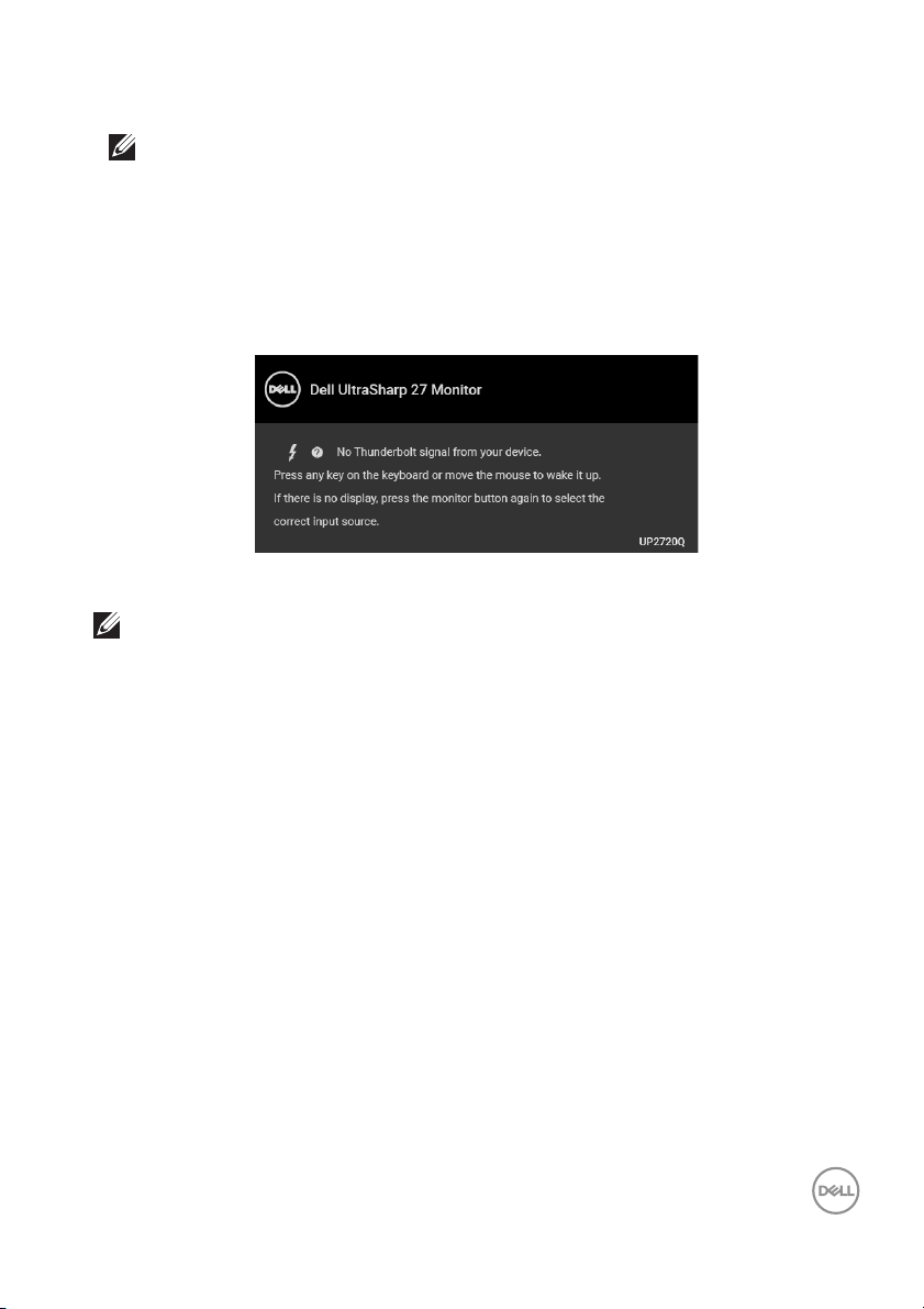
If you press any button other than the power button, the following message will
appear depending on the selected input:
NOTE: The message may be slightly different according to the
connected input signal.
62 │ Operating the Monitor
Page 63

If either Thunderbolt, HDMI, or DP input is selected and the corresponding cable
is not connected, a floating dialog box as shown below appears.
NOTE: The message may be slightly different according to the
connected input signal.
When the monitor is under DP/HDMI input and a Thunderbolt™ 3 Active cable is
connected to a notebook that supports DP Alternate Mode, if
enabled, the following message appears:
USB-C Charging is
When Factory Reset is selected, the following message appears:
Operating the Monitor │ 63
Page 64

When Yes is selected, the following message appears:
See Trou bl es hoot in g for more information.
Setting the Maximum Resolution
To set the maximum resolution for the monitor:
In Windows® 7, Windows® 8 and Windows® 8.1:
1. For Windows® 8 and Windows® 8.1 only, select the Desktop tile to switch to
classic desktop.
2. Right-click on the desktop and click Screen Resolution.
3. Click the Dropdown list of the Screen Resolution and select 3840 x 2160.
4. Click OK.
In Windows® 10:
1. Right-click on the desktop and click Display settings.
2. Click Advanced display settings.
3. Click the dropdown list of Resolution and select 3840 x 2160.
4. Click Apply.
If you do not see 3840 x 2160 as an option, you may need to check whether your
graphic card supports 4K@60 Hz. If it does support 4K@60 Hz, update your
graphic driver. If it does not support 4K@60 Hz, depending on your computer,
complete one of the following procedures:
If you have a Dell desktop or portable computer:
•Go to http://www.dell.com/support, enter your service tag, and download
the latest driver for your graphics card.
64 │ Operating the Monitor
Page 65

If you are using a non-Dell computer (portable or desktop):
• Go to the support site for your computer and download the latest graphic
drivers.
• Go to your graphics card website and download the latest graphic drivers.
Performing Color Calibration
Perform Calibration with the built-in colorimeter to calibrate the color of your
monitor.
Using the OSD menu
1. Using the OSD menu, set the calibration criteria based on your preference.
Then select Calibrate Now.
2. The following message appears, select Yes to continue the process.
Operating the Monitor │ 65
Page 66

3. Cal ibration will start automaticall y.
Using the Shortcut Key with video signal
1. Press any of the Function buttons to display the shortcut keys.
2. Press the button.
3. The fol lowing message appears, select Yes to continue the process.
66 │ Operating the Monitor
Page 67

4. Calibration wil l start automatically.
Using the Shortcut Key without video signal
You can perform calibration for the monitor without acquiring an input signal from
the computer.
1. Press any of the Function buttons to display the shortcut keys.
2. Press the button.
Operating the Monitor │ 67
Page 68

3. Cal ibration will start automaticall y.
NOTE: Calibration at Portrait Mode is not recommended.
NOTE: For detailed functionality, see Calibration.
Stopping the Calibration Process
You can stop the calibration process at any time.
1. During calibration process, press any of the Function buttons, the fol lowing
message appears.
2. Select Yes to stop the process.
68 │ Operating the Monitor
Page 69

Performing Color Validation
Perform Val idation on color calibration with the built-in colorimeter.
Using the OSD menu
1. Using the OSD menu, set the validation criteria based on your preference.
Then select Validate Now to start the validation process.
2. The following message appears, select Yes to continue the process.
Operating the Monitor │ 69
Page 70

3. Validation wil l start automatical ly.
Using the shortcut key without video signal
You can perform validation for the monitor without acquiring an input signal from
the computer.
1. Press any of the Function buttons to display the shortcut keys.
2. Press the button.
70 │ Operating the Monitor
Page 71

3. The following message appears, select Yes to continue the process.
NOTE: Validation at Portrait Mode is not recommended.
NOTE: For detailed functionality, see Val idation.
Stopping the Validation Process
You can stop the validation process at any time.
1. During validation process, press any of the Function buttons, the following
message appears.
2. Select Yes to stop the process.
Operating the Monitor │ 71
Page 72

Using the Tilt, Swivel, and Vertical Extension
NOTE: This is applicable for a monitor with a stand. When any other
stand is bought, please refer to the respective stand setup guide for set
up instructions.
Til t, S w i ve l
With the stand attached to the monitor, you can tilt and swivel the monitor for the
most comfortable viewing angle.
NOTE: The stand is detached when the monitor is shipped from the
factory.
72 │ Operating the Monitor
Page 73

Vertical Extension
NOTE: The stand extends vertically up to 130 mm. The figure below
illustrates how to extend the stand vertically.
Rotating the Monitor
Before you rotate the monitor, your monitor should be fully vertically extended
(
Vertical Extension) and fully tilted up to avoid hitting the bottom edge of the
monitor.
Operating the Monitor │ 73
Page 74

Rotate clockwise
Rotate counterclockwise
74 │ Operating the Monitor
Page 75

Troubleshooting
WARNING: Before you begin any of the procedures in this section,
fol low the Safety Instructions.
Sel f-Test
Your monitor provides a self-test feature that allows you to check whether your
monitor is functioning properly. If your monitor and computer are properly
connected but the monitor screen remains dark, run the monitor self-test by
performing the following steps:
1. Turn off both your computer and the monitor.
2. Unplug the video cable from the back of the computer.
3. Turn on the monitor.
The floating dialog box should appear on-screen (against a black background), if the
monitor cannot sense a video signal and is working correctly. While in self-test
mode, the power LED remains white. Also, depending upon the selected input, the
dialog shown below will continuously scroll through the screen.
NOTE: The message may be slightly different according to the
connected input signal.
4. This box also appears during normal system operation, if the video cable
becomes disconnected or damaged.
5. Turn Off your monitor and reconnect the video cable; then turn On both your
computer and the monitor.
If your monitor screen remains blank after you use the previous procedure, check
your video controller and computer, because your monitor is functioning properly.
Tro ub l es hoot in g │ 75
Page 76

Built-in Diagnostics
Your monitor has a built-in diagnostic tool that helps you determine if the screen
abnormality you are experiencing is an inherent problem with your monitor, or with
your computer and video card.
NOTE: You can run the built-in diagnostics only when the video cable is
unplugged and the monitor is in self-test mode.
To run the built-in diagnostics:
1. Ensure that the screen is clean (no dust particles on the surface of the
screen).
2. Unplug the video cable(s) from the back of the computer or monitor. The
monitor then goes into the self-test mode.
3. Press and hold Button 6 on the front panel for 4 seconds, the following
message appears:
76 │ Tro ub l e sh o ot in g
Page 77

4. Press the button to highlight the Diagnostics icon, then press the
button, and a gray screen appears.
5. Carefully inspect the screen for abnormalities.
6. Press Button 1 on the front panel again. The color of the screen changes to
red.
7. Inspect the display for any abnormalities.
8. Repeat steps 6 and 7 to inspect the display in green, blue, black, white and
text screens.
The test is complete when the text screen appears. To exit, press Button 1 again.
If you do not detect any screen abnormalities upon using the built-in diagnostic tool,
the monitor is functioning properly. Check the video card and computer.
Always On USB Type-C (Thunderbolt™) Charging
The monitor allows you to charge your notebook or mobile devices through the
Thunderbolt™ 3 Active cable even when the monitor is powered off. See
Charging for more information. You may need to update to the latest firmware for
this feature to function properly.
You may verify your current firmware revision in Firmware. If this is not available,
go to the Dell download support site for the latest application installer (Monitor
Firmware Update Utility.exe) and refer to the Firmware Update Instruction
User’s Guide:
www.dell.com/UP2720Q
Tro ub l e sh o ot in g │ 77
USB-C
Page 78

Common Problems
The following table contains general information about common monitor problems
you might encounter and the possible solutions:
Common
Symptoms
No Video/
Power LED off
No Video/
Power LED on
Poor Focus Picture is
Shaky/Jittery
Video
What You
Experience
No picture • Ensure that the video cable connecting the
No picture or
no
brightness
fuzzy, blurry,
or ghosting
Wavy picture
or fine
movement
Possible Solutions
monitor and the computer is properly
connected and secure.
• Verify that the power outlet is functioning
properly using any other electrical equipment.
• Ensure that the power button is pressed ful l y.
• Ensure that the correct input source is
selected in the
• Increase brightness & contrast controls via
OSD.
• Perform monitor self-test feature check.
• Check for bent or broken pins in the video
cable connector.
• Run the built-in diagnostics.
• Ensure that the correct input source is
selected in the
• Eliminate video extension cables.
• Reset the monitor to factory settings.
• Change the video resolution to the correct
aspect ratio.
• Reset the monitor to factory settings.
• Check environmental factors.
• Relocate the monitor and test in another
room.
• Del l monitors are designed to work optimally
with Del l supplied inbox cables. Dell does not
guarantee the video quality and performance
when using non-Del l cables.
Input Source menu.
Input Source menu.
78 │ Tro ub l e sh o ot in g
Page 79

Missing Pixels LCD screen
has spots
Stuck-on Pixels LCD screen
has bright
spots
Brightness
Problems
Geometric
Distortion
Horizontal/
Vertica l Lines
Synchronization
Problems
Safety Related
Issues
Picture too
dim or too
bright
Screen not
centered
correctly
Screen has
one or more
lines
Screen is
scrambled or
appears torn
Visible signs
of smoke or
sparks
•Cycle power On-Off.
• Pixel that is permanently Off is a natural
defect that can occur in LCD technology.
• For more information on Del l Monitor Quality
and Pixel Policy, see Dell Support site at:
http://www.dell.com/support/monitors.
•Cycle power On-Off.
• Pixel that is permanently off is a natural
defect that can occur in LCD technology.
• For more information on Del l Monitor Quality
and Pixel Policy, see Dell Support site at:
http://www.dell.com/support/monitors.
• Reset the monitor to factory settings.
• Adjust brightness & contrast controls via
OSD.
• Reset the monitor to factory settings.
• Adjust horizontal & vertical controls via OSD.
• Reset the monitor to factory settings.
• Perform monitor self-test feature check and
determine if these lines are also in self-test
mode.
• Check for bent or broken pins in the video
cable connector.
• Run the built-in diagnostics.
• Reset the monitor to factory settings.
• Perform monitor self-test feature check to
determine if the scrambled screen appears in
sel f-test mode.
• Check for bent or broken pins in the video
cable connector.
• Restart the computer in the safe mode.
• Do not perform any troubleshooting steps.
•Contact Dell immediately.
Tro ub l e sh o ot in g │ 79
Page 80

Intermittent
Problems
Missing Color Picture
Wrong Color Picture color
Image retention
from a static
image left on
the monitor for
a long period of
time
Image Ghosting Fast moving
Monitor
malfunctions
on & off
missing color
not good
Faint
shadow from
the static
image
displayed
appears on
the screen
images leave
a trail of
shadow
images
• Ensure that the video cable connecting the
monitor to the computer is connected
properly and is secure.
• Reset the monitor to factory settings.
• Perform monitor self-test feature check to
determine if the intermittent problem occurs
in sel f-test mode.
• Perform monitor self-test feature check.
• Ensure that the video cable connecting the
monitor to the computer is connected
properly and is secure.
• Check for bent or broken pins in the video
cable connector.
• Change the settings of the Preset Modes in
the Color menu OSD depending on the
application.
• Adjust R/G/B value under Custom Color in
Color menu OSD.
•Change the Input Color Format to PC RGB
or YPbPr in the Color menu OSD.
• Run the built-in diagnostics.
• Use the Power Management feature to turn
off the monitor at all times when not in use
(for more information, see
Management Modes).
• Alternatively, use a dynamicall y changing
screensaver.
• Change the Response Time in the Display
menu.
Power
80 │ Tr ou b le sh oo ti ng
Page 81

Product Specific Problems
Specific
Symptoms
Screen image
is too small
Cannot adjust
the monitor
with the
buttons on the
front panel
No Input Signal
when user
controls are
pressed
The picture
does not fill
the entire
screen
What You
Experience
Image is
centered on
screen, but
does not fill
entire viewing
area
OSD does not
appear on the
screen
No picture,
the LED light
is white
The picture
cannot fill the
height or
width of the
screen
Possible Solutions
• Check the Aspect Ratio setting in the
Display menu OSD.
• Reset the monitor to factory settings.
• Turn Off the monitor, unplug the power cord,
plug it back, and then turn On the monitor.
• Check whether the OSD menu is locked. If
yes, press and hold the Menu/function button
next to the Power button for 4 seconds to
unlock (for more information, see
• Check the signal source. Ensure the computer
is not in the power saving mode by moving
the mouse or pressing any key on the
keyboard.
• Check whether the signal cable is plugged in
properly. Re-plug the signal cable if
necessary.
• Reset the computer or video player.
• Due to different video formats (aspect ratio)
of DVDs, the monitor may display in full
screen.
• Run the built-in diagnostics.
Lock).
Tro ub l es hoot in g │ 81
Page 82

No video in
PBP mode at
HDMI port
when playing
movie content
No video at
HDMI port
When
connected to
some docking
device at
HDMI port,
there is no
video at PBP
mode after
the monitor is
turned Off
and then
turned On
again.
When
connected to
some docking
device at
HDMI port,
there is no
video when
unplug/plug
Thunderbol t
™ cable from
the
Notebook.
• Unplug/plug HDMI cable from docking device
output.
• Unplug the HDMI cable from docking device,
then plug the docking Thunderbolt™ cable to
Notebook. Plug the HDMI cable 7 seconds
later.
82 │ Tro ub l e sh o ot i ng
Page 83

Universal Serial Bus (USB) Specific Problems
Specific
Symptoms
USB interface
is not working
Thunderbolt™
3 port does not
suppl y power
No video
when using
Thunderbolt™
3 connection
after DC On/
Off, wake up
from Sleep
What You
Experience
USB
peripherals
are not
working
USB
peripherals
can not be
charged
No picture is
showing
Possible Solutions
• Unplug/plug Thunderbolt™ 3 Active cable.
• Check that your monitor is turned On.
• Reconnect the Thunderbolt™ 3 Active cable
to your computer.
• Reconnect the USB peripherals (downstream
connector).
• Switch Off and then turn On the monitor
again.
• Reboot the computer.
• Some USB devices like external portable HDD
require higher electric current; connect the
device directly to the computer system.
• Check that the connected device is compliant
with the Thunderbol t™ 3 specification. The
Thunderbol t™ 3 port supports USB 3.1 with
speeds up to 10 Gbps and an output of 90 W.
• Check that you use the Thunderbolt™ 3
Active cable shipped with your monitor.
• Unplug/plug Thunderbolt™ 3 Active cable.
• Check that the connected device is compliant
with Thunderbol t™ 3 specification.
• Check that the Thunderbol t™ 3 Active cable
connected from the computer to the USB-C
upstream port on the monitor.
• Use the Thunderbol t™ 3 Active cable that
was shipped with the monitor.
• In Windows, click on the Thunderbolt™ logo
in Windows system tray (located at bottom
right corner of the screen). Under Approve
Thunderbol t Devices, select “Always
Connect” for this monitor.
Tro ub l e sh o ot in g │ 83
Page 84

No video when
using USB-C
DP Al t-Mode
connection
after DC On/
Off, wake up
from Sleep
High Speed
USB 3.2
interface is
slow
Wireless
mouse is not
working or
lagging
No picture is
showing
High Speed
USB 3.2
peripherals
working
slowly or not
working at al l
Do not
respond or
responds
slowly
•Unplug/plug USB-C cable.
• The monitor ships with a Thunderbol t™ 3
Active cable. This cable does not work with a
USB-C DP Al t-Mode source. If you are using a
computer with USB-C DP Alt-Mode
connection, please purchase a USB-C DP
cable separately.
• Check that your computer is USB 3.2capable.
• Some computers have USB 3.1, USB 3.0, USB
2.0, and USB 1.1 ports. Ensure that the correct
USB port is used.
• Reconnect the upstream cable to your
computer.
• Reconnect the USB peripherals (downstream
connector).
• Reboot the computer.
• Increase the distance between the USB
peripherals and the wireless USB receiver.
• Position your wireless USB receiver as close
as possible to the wireless mouse.
• Use a USB-extender cable to position the
wireless USB receiver as far away as possible
from the USB 3.2 port.
84 │ Tr ou b le sh oo ti ng
Page 85

Appendix
WARNING: Safety Instructions
WARNING: Use of controls, adjustments, or procedures other than
those specified in this documentation may result in exposure to shock,
electrical hazards, and/or mechanical hazards.
For information on safety instructions, see the Safety, Environmental, and
Regulatory Information (SERI).
FCC Notices (U.S. Only) and Other Regulatory Information
For FCC notices and other regulatory information, see the regulatory compliance
website located at
Contact Del l
For customers in the United States, call 800-WWW-DELL (800-999-3355).
NOTE: If you do not have an active Internet connection, you can find
contact information on your purchase invoice, packing slip, bill, or Dell
product catalog.
Dell provides several online and telephone-based support and service
options. Availability varies by country and product, and some services may
not be available in your area.
• Online technical assistance ─ www.dell.com/support/monitors
•Contacting Dell ─ www.dell.com/contactdell
www.dell.com/regulatory_compliance.
Appendix │ 85
Page 86

Video and USB Support over USB-C
Video resolution and USB support when connecting to monitor via USB-C.
Video USB
TBT3
Upstream
Connection
on host
computer
USB-A USB A-to-C* No No No USB2.0
USB-C
(Data only)
USB-C
(MFDP)
TBT3
Cable used
(Host
computer to
Monitor port
6-1)
USB-C
MFDP
TBT3
Passive
TBT3
Active*
USB-C
MFDP
TBT3
Passive
TBT3
Active*
USB-C
MFDP
TBT3
Passive
TBT3
Active*
4K
(Direct
connect)
No No No USB2.0
No No No USB2.0
No No USB2.0 USB2.0 USB2.0
Yes No No USB2.0 USB2.0
Yes No No USB2.0 USB2.0
No No USB2.0 USB2.0 USB2.0
Yes No No USB2.0
Yes No Yes USB2.0
Yes Yes Yes USB2.0
4K
(Daisy-
chained)
device
connected
to TBT3
downstream
(Monitor
port 6-2)
USB-C
device
connected
to TBT3
down-
stream
(Monitor
port 6-2)
USB
device
connected
to USB-A
down-
stream
(Monitor
port 7-1 to
7-4 )
USB2.0/
3.2
USB2.0/
3.2
USB2.0/
3.2
USB2.0/
3.2
USB2.0/
3.2
USB2.0/
3.2
* Cable shipped with monitor.
NOTE: TBT3 is the abbreviation of Thunderbolt™ 3.
NOTE: Refer to Bottom View for monitor port assignment.
NOTE: Refer to Connecting the monitor for Thunderbolt™ Multi-
Stream Transport (MST) function for Daisy chain connection.
86 │ Appendix
Page 87

Purchasing a Thunderbolt™ 3 Passive Cable
Region Link
https://www.dell.com/en-us/shop/accessories/apd/a9905599
Del l
Websi te
US https://www.belkin.com/us/p/P-F2CD081/
EMEA
Asia
NOTE: The links are for your reference only, and are subject to change
without notice.
https://www.dell.com/en-us/shop/accessories/apd/a9905597
https://www.del l.com/en-us/shop/accessories/apd/a9269731
https://www.delock.com/produkte/G_84846/merkmale.html/
https://www.hama.cz/hama-kabel-thunderbolt-3-usb-c-typ-cvidlice--vidlice-20-gb-s-100-w-1-m/
https://www.lindy-international.com/Thunderbolt-3-Cable2m.htm?websale8=ld0101.ld020102&pi=41557
https://www.lindy.com.tw/ecommerce/cable-adapter/
thunderbol t3/41557.html
Appendix │ 87
 Loading...