

Page 1

Dell PowerEdge RAID Controller (PERC) 9
User’s Guide
Regulatory Model: UCPA-901, UCPB-900, UCSA-901,
UCSB-900, UCSE-900, and UCPE-900
Page 2
Notes, cautions, and warnings
NOTE: A NOTE indicates important information that helps you make better use of your computer.
CAUTION: A CAUTION indicates either potential damage to hardware or loss of data and tells you
how to avoid the problem.
WARNING: A WARNING indicates a potential for property damage, personal injury, or death.
Copyright © 2015 Dell Inc. All rights reserved. This product is protected by U.S. and international copyright and
intellectual property laws. Dell™ and the Dell logo are trademarks of Dell Inc. in the United States and/or other
jurisdictions. All other marks and names mentioned herein may be trademarks of their respective companies.
2015 - 04
Rev. A03
Page 3

Contents
1 Overview.................................................................................................................9
Supported operating systems............................................................................................................. 14
PERC card specifications.....................................................................................................................15
Management applications for PERC cards......................................................................................... 17
Comprehensive embedded management ...................................................................................17
Dell OpenManage Storage Management..................................................................................... 17
Related documentation...................................................................................................................... 18
2 Getting started with your PERC card..............................................................19
Installing the operating system and the PERC card on a base system............................................. 19
Installing the PERC card on a system with the operating system pre-installed...............................20
Installing the operating system on a system with the PERC card pre-installed............................... 21
Setting up the system with the PERC card and the operating system pre-installed .......................22
Configuring settings of a replaced PERC card on a system with operating system pre-
installed................................................................................................................................................23
3 Features................................................................................................................ 25
PERC 9 personality management.......................................................................................................25
T10 protection information................................................................................................................ 25
Enabling T10 PI..............................................................................................................................25
Disabling T10 PI.............................................................................................................................26
Secure firmware update......................................................................................................................26
Improved RAID 10 configuration........................................................................................................26
4KB block size disk drives................................................................................................................... 26
Physical disk power management......................................................................................................26
Configured spin down delay.........................................................................................................27
Types of virtual disk initialization........................................................................................................ 27
Full initialization............................................................................................................................. 27
Fast initialization............................................................................................................................28
Background initialization.................................................................................................................... 28
Consistency checks............................................................................................................................ 28
Disk roaming....................................................................................................................................... 29
Using disk roaming........................................................................................................................29
FastPath............................................................................................................................................... 29
Configuring FastPath-capable virtual disks..................................................................................29
Virtual disk migration.......................................................................................................................... 30
Migrating virtual disks....................................................................................................................30
Virtual disk write cache policies..........................................................................................................31
3
Page 4

Conditions under which write-back is employed........................................................................31
Conditions under which forced write-back with no battery is employed..................................31
Virtual disk read cache policies...........................................................................................................31
Reconfiguration of virtual disks.......................................................................................................... 32
Fault tolerance.................................................................................................................................... 34
The SMART Feature.......................................................................................................................34
Patrol Read.....................................................................................................................................35
Physical disk failure detection.......................................................................................................35
Using persistent hot spare slots....................................................................................................35
Physical disk hot swapping........................................................................................................... 36
Using replace member and revertible hot spares........................................................................36
Controller cache preservation......................................................................................................36
Battery Transparent Learn Cycle...................................................................................................37
Non-RAID disks support................................................................................................................37
4 Deploying the PERC card..................................................................................39
Removing the PERC 9 adapter........................................................................................................... 39
Installing the PERC 9 adapter..............................................................................................................41
Removing the PERC 9 mini monolithic controller.............................................................................41
Replacing the battery of a H730P mini monolithic card............................................................. 42
Installing the PERC 9 mini monolithic controller.............................................................................. 44
Removing a H730P slim card............................................................................................................. 45
Replacing the battery of a H730P slim card.................................................................................46
Installing a H730P slim card............................................................................................................... 48
Removing the PERC 9 mini blade controller.....................................................................................48
Replacing the tethered battery of a PERC 9 mini blade card......................................................49
Installing the PERC 9 mini blade controller....................................................................................... 53
Removing the PERC FD33xD Card.....................................................................................................54
Replacing the battery of a PERC FD33xD card............................................................................ 55
Installing the PERC FD33xD card....................................................................................................... 56
5 Driver installation............................................................................................... 58
Creating the device driver media....................................................................................................... 58
Downloading drivers from the Dell support website...................................................................58
Downloading drivers from the Dell systems service and diagnostic tools media .....................59
Windows driver installation.................................................................................................................59
Installing the driver during a Windows Server 2008 R2 and newer installation......................... 59
Installing the driver after Windows Server 2008 R2 and newer installation .............................. 59
Updating PERC 9 driver for existing Windows Server 2008 R2 and newer................................60
Linux driver installation.......................................................................................................................60
Installing or updating the RPM driver package with KMOD support...........................................61
Installing or updating the RPM driver package with KMP support.............................................. 61
4
Page 5

6 BIOS Configuration Utility................................................................................62
Entering the BIOS Configuration Utility............................................................................................. 62
Exiting the Configuration Utility......................................................................................................... 62
Menu navigation controls...................................................................................................................63
Setting up virtual disks........................................................................................................................ 64
BIOS Configuration Utility menu options.......................................................................................... 66
Virtual disk management.............................................................................................................. 66
Virtual disk actions........................................................................................................................ 68
Physical disk management (PD Mgmt).........................................................................................69
Physical disk actions......................................................................................................................69
Rebuild...........................................................................................................................................70
Controller management (Ctrl Mgmt)........................................................................................... 70
Controller management actions...................................................................................................71
Foreign configuration view........................................................................................................... 72
Virtual Disk Management.................................................................................................................... 72
Creating virtual disks..................................................................................................................... 72
Selecting virtual disk parameters.................................................................................................. 73
Initializing virtual disks...................................................................................................................73
Checking data consistency...........................................................................................................74
Running a data consistency check...............................................................................................74
Importing or clearing foreign configurations using the VD mgmt menu...................................74
Importing or clearing foreign configurations using the foreign configuration view screen......75
Break mirror...................................................................................................................................76
Managing preserved cache........................................................................................................... 77
Managing dedicated hot spares....................................................................................................78
Deleting virtual disks......................................................................................................................78
Deleting disk groups......................................................................................................................79
Clearing the configuration............................................................................................................79
Physical Disk Management................................................................................................................. 79
Setting LED blinking...................................................................................................................... 79
Creating global hot spares............................................................................................................80
Removing global or dedicated hot spares...................................................................................80
Replacing an online physical disk.................................................................................................80
Restrictions and limitations........................................................................................................... 81
Stopping background initialization............................................................................................... 81
Performing a manual rebuild of an individual physical disk.........................................................81
Controller Management..................................................................................................................... 82
Enabling boot support.................................................................................................................. 82
Enabling boot support for a BIOS-enabled controller................................................................ 82
Enabling BIOS stop on error......................................................................................................... 83
Disabling BIOS stop on error........................................................................................................ 83
5
Page 6

Enabling auto import.....................................................................................................................83
Disabling auto import....................................................................................................................83
Restoring factory default settings.................................................................................................84
7 UEFI/HII RAID configuration utility.................................................................85
Entering the UEFI configuration utility............................................................................................... 85
Exiting the UEFI configuration utility..................................................................................................85
Navigating to Dell PERC 9 configuration utility.................................................................................85
Configuration management...............................................................................................................86
Creating virtual disks.....................................................................................................................86
Creating profile based virtual disks...............................................................................................87
Converting physical disks to RAID capable disk...........................................................................87
Converting physical disks to non-RAID disk................................................................................ 87
Viewing disk group properties...................................................................................................... 87
Viewing disk group properties...................................................................................................... 87
Managing foreign configurations on a RAID controller.............................................................. 88
Deleting existing configurations on a RAID controller................................................................88
Controller management.....................................................................................................................88
Restoring factory settings for the controller................................................................................88
Saving controller events............................................................................................................... 88
Enabling security for the controller..............................................................................................89
Saving debug log...........................................................................................................................89
Switching the controller to HBA mode........................................................................................89
Switching the controller to RAID mode.......................................................................................90
Virtual disk management....................................................................................................................90
Viewing virtual disk properties......................................................................................................90
Viewing physical disks associated with a virtual disk...................................................................90
Physical disk management..................................................................................................................91
Viewing physical disk properties................................................................................................... 91
Hardware components management................................................................................................ 91
Viewing battery properties............................................................................................................ 91
Viewing physical disks associated with an enclosure..................................................................92
8 Security key and RAID management.............................................................. 93
Security key implementation..............................................................................................................93
Security key management in the BIOS configuration utility............................................................. 93
Local Key Management (LKM)...................................................................................................... 94
Creating a security key..................................................................................................................94
Changing the security key............................................................................................................ 94
Deleting a security key..................................................................................................................95
Creating secured virtual disks.......................................................................................................95
Securing pre-existing virtual disks................................................................................................95
6
Page 7

Importing or clearing secured foreign configurations and secure disk migration.................... 96
Instant secure erase...................................................................................................................... 97
9 Troubleshooting.................................................................................................98
BIOS configuration utility error messages......................................................................................... 98
Discovery error message.............................................................................................................. 98
Extra enclosure error message.....................................................................................................98
Missing disks in virtual disk error message...................................................................................98
Previous configuration of disks removed error message............................................................99
Missing virtual disks error message.............................................................................................. 99
Dirty cache data error message....................................................................................................99
BIOS disabled error message......................................................................................................100
Drive Configuration Changes Error Message............................................................................ 100
Adapter at baseport not responding error message................................................................. 100
Offline or missing virtual drives with preserved cache error message......................................101
Virtual disks offline error message..............................................................................................101
Virtual disks degraded error message.........................................................................................101
Virtual disks partially degraded error message...........................................................................101
Memory or battery problem error message...............................................................................102
Firmware fault state error message............................................................................................102
Foreign configuration found error message..............................................................................102
Foreign configuration not found in <ctrl> <R> error message................................................. 102
Previous configuration cleared or missing error message........................................................103
Invalid SAS topology detected error message........................................................................... 103
Configured disks removed or not accessible error message....................................................103
Degraded state of virtual disks..........................................................................................................103
Memory errors...................................................................................................................................104
Preserved Cache State......................................................................................................................104
Security key errors............................................................................................................................ 104
Secured foreign import errors....................................................................................................104
Failure to select or configure non Self-Encrypting Disks (non-SED)........................................104
Failure to delete security key...................................................................................................... 105
Failure to instant secure erase task on physical disks................................................................105
General Issues................................................................................................................................... 105
PERC card has yellow bang in device manager.........................................................................105
PERC card not seen in device manager..................................................................................... 105
Physical disk issues............................................................................................................................105
Physical disk in failed state..........................................................................................................105
Unable to rebuild a fault tolerant virtual disk.............................................................................106
Fatal error or data corruption reported......................................................................................106
Physical disk displayed as blocked............................................................................................. 106
Multiple disks become inaccessible........................................................................................... 106
7
Page 8

Rebuilding a failed physical disk................................................................................................. 107
Virtual disk fails during rebuild using a global hot spare............................................................107
Virtual disk fails during rebuild using a dedicated hot spare..................................................... 107
Physical disk fails during reconstruction on redundant virtual disk.......................................... 107
Virtual disk fails rebuild using a dedicated hot spare.................................................................107
Physical disk takes a long time to rebuild...................................................................................107
SMART errors.....................................................................................................................................108
Smart error detected on a physical disk in a redundant virtual disk......................................... 108
Smart error detected on a physical disk in a non-redundant virtual disk.................................108
Replace member errors....................................................................................................................108
Source disk fails during replace member operation..................................................................109
Target disk fails............................................................................................................................109
General disk fails......................................................................................................................... 109
Linux operating system errors..........................................................................................................109
Virtual disk policy is assumed as write-through error message................................................109
Unable to register SCSI device error message........................................................................... 110
Disk Carrier LED Indicators............................................................................................................... 110
UEFI error messages..........................................................................................................................110
Unhealthy Status of the Drivers...................................................................................................110
10 Appendix: RAID description..........................................................................112
Summary of RAID levels.................................................................................................................... 112
RAID terminology.............................................................................................................................. 112
Disk striping..................................................................................................................................112
Disk mirroring...............................................................................................................................113
Spanned RAID levels.................................................................................................................... 113
Parity data.....................................................................................................................................114
11 Getting help......................................................................................................115
Contacting Dell..................................................................................................................................115
Documentation feedback..................................................................................................................115
Locating your system Service Tag.................................................................................................... 115
8
Page 9
1
Overview
The Dell PowerEdge Expandable RAID Controller (PERC) 9 Series of cards consist of the H330, H730,
H730P, and H830 cards.
• PERC H330: The PERC H330 is a general purpose RAID solution card. The card is available in Adapter
(low profile and full height), Mini Monolithic, and Mini Blade form factors for internal storage and tape
devices.
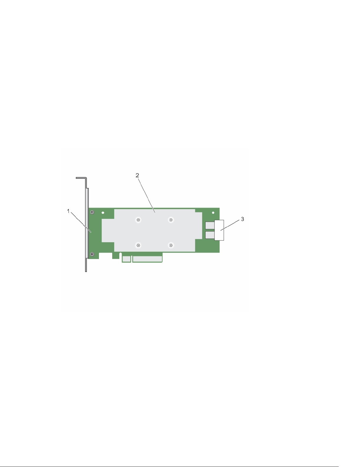
Figure 1. Features of PERC H330 adapter card
1. PERC H330 adapter 2. heat sink
3. SAS cable connectors
9
Page 10
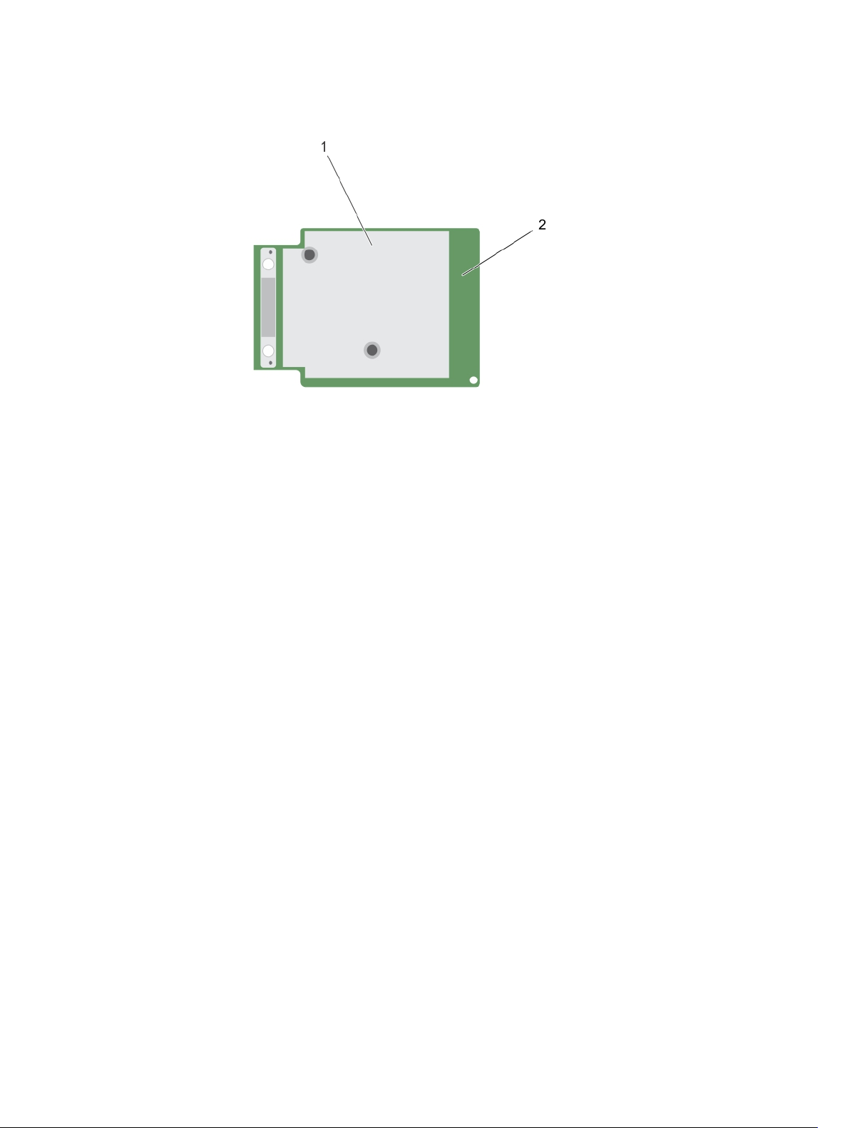
Figure 2. Features of PERC H330 mini monolithic card
1. heat sink 2. PERC H330 mini monolithic card
• PERC H730: The PERC H730 is a RAID solution card consisting of a minimum of 1 GB Non-Volatile
Cache and is available in the Adapter (low profile and full height), Mini Monolithic, and Mini Blade form
factors for internal storage.
10
Page 11

Figure 3. Features of PERC H730 card
1. PERC H730 card 2. heat sink
3. battery cable
4. battery carrier
5. SAS cable connectors
11
Page 12
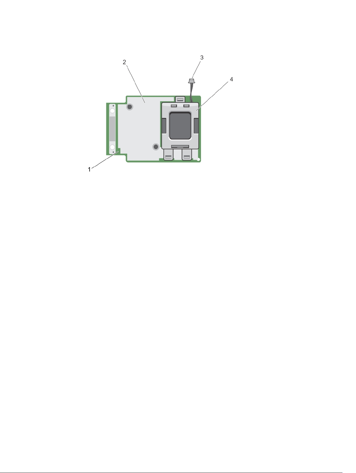
Figure 4. Features of PERC H730/H730P mini monolithic card
1. PERC H730/H730P card 2. heat sink
3. battery cable
4. battery carrier
• PERC H730P: The PERC H730P is the performance RAID solution card consisting of 2 GB Non-
Volatile Cache and is available in the Adapter (low profile and full height), Slim, and Mini Monolithic
form factors for internal storage.
12
Page 13
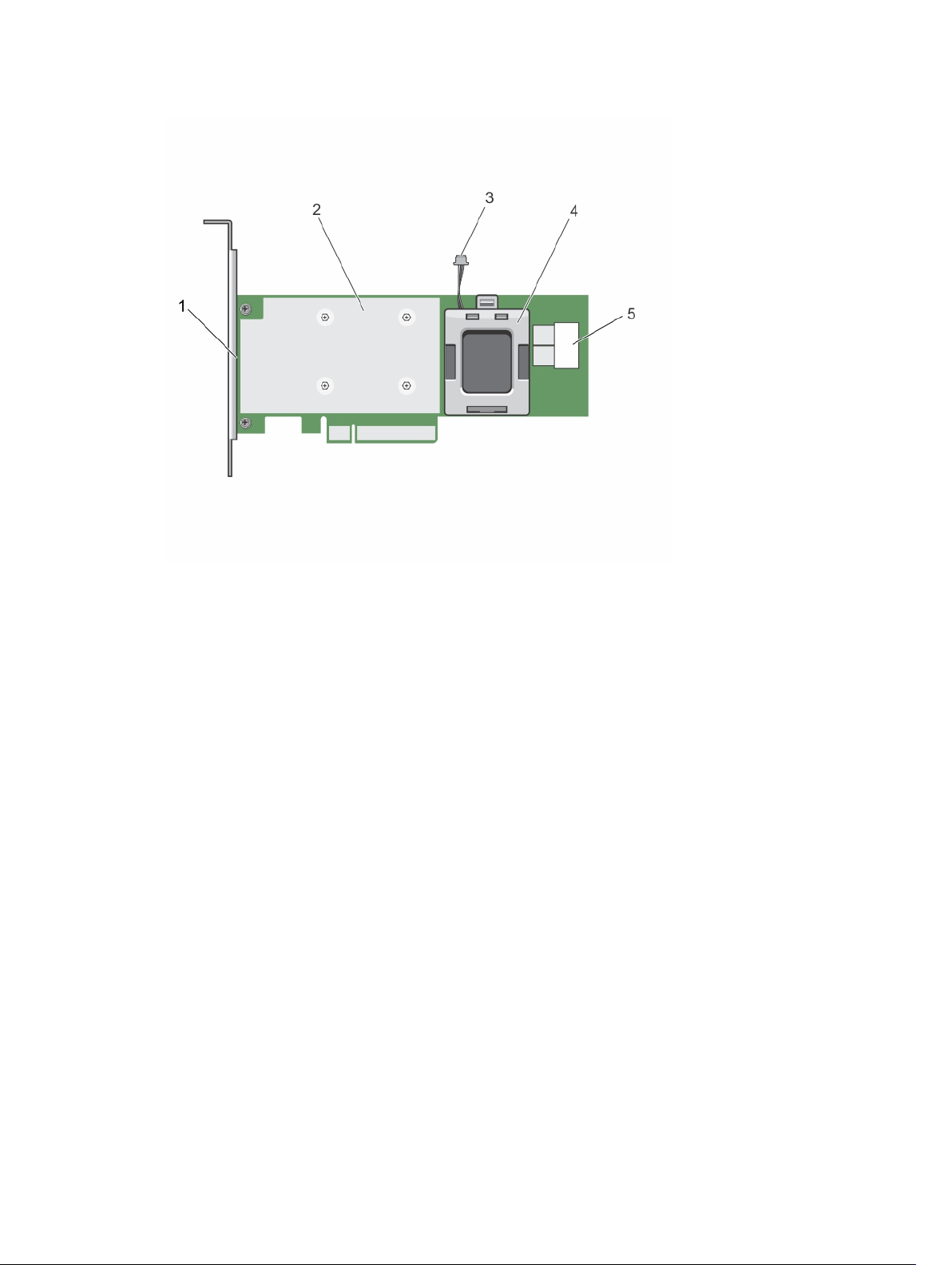
Figure 5. Features of PERC H730P adapter card
1. PERC H730P card 2. heat sink
3. battery cable
4. battery carrier
5. SAS cable connectors
• PERC H830: The PERC H830 is similar to the H730P solution, except that it supports external storage.
The PERC H830 is only available in the Adapter (low profile and full height) form factor.
13
Page 14
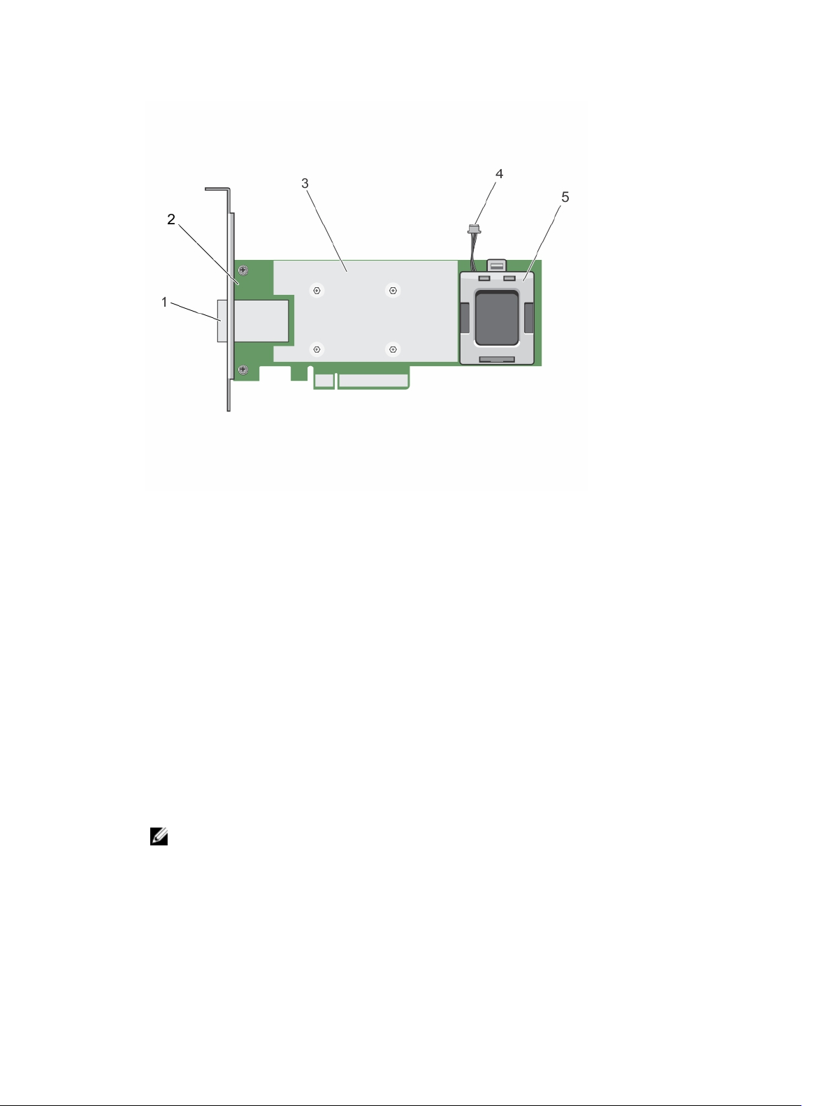
Figure 6. Features of PERC H830 adapter card
1. external SAS cable connectors 2. PERC H830 adapter
3. heat sink
5. battery carrier
4. battery cable
Supported operating systems
The PERC 9 series cards support the following operating systems:
• Microsoft Windows Server 2012
• Microsoft Windows Server 2012 R2
• Microsoft Windows Server 2008 R2
• Microsoft Windows Server 2008 R2 SP1
• VMware ESXi 5.1 Update 2
NOTE: The PERC 9 driver for VMware ESXi is bundled with the VMware ISO image available from
Dell. For more information, see dell.com/virtualizationsolutions.
• VMware ESXi 5.5 Update 2
• Red Hat Enterprise Linux version 6.5 (64-bit)
• Red Hat Enterprise Linux 6.5 for HPC Compute Node
• Red Hat Enterprise Virtualization 4.0 (64-bit)
14
Page 15
• SUSE Linux Enterprise Server version 11 SP3 (64-bit)
• Red Hat Enterprise Linux version 7
NOTE: For the latest list of supported operating systems and driver installation instructions, see the
system documentation at dell.com/support/manuals. For specific operating system service pack
requirements, see the Drivers and Downloads section at dell.com/support/manuals.
PERC card specifications
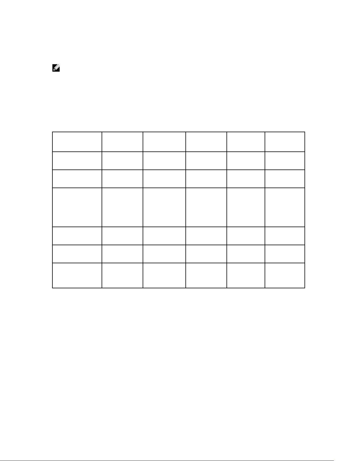
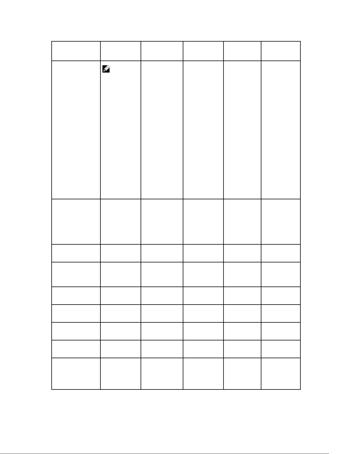
The table below lists and describes the different PERC cards that comprise the PERC 9 series and their
specifications:
Feature PERC H330 PERC H730 PERC H730P PERC H830 PERC
RAID Levels 0, 1, 5, 10, 50 0, 1, 5, 6, 10, 50, 600, 1, 5, 6, 10,
50, 60
Enclosures per
port
Processor Dell Adapter
Battery Backup
Unit
Non-Volatile
cache
Cache policy No 1 GB DDR3
Not applicable Not applicable Not applicable 8 (4 per port) Not applicable
Dell Adapter
SAS RAID-onChip, 8-port
with LSI 3008
chipset
No Yes Yes Yes Yes
None Yes Yes Yes Yes
SAS RAID-on-
Chip, 8-port
with LSI 3108
chipset
1333 Mhz
cache
Dell Adapter
SAS RAID-onChip, 8-port
with LSI 3108
chipset
2 GB DDR3
1866 Mhz
cache
0, 1, 5, 6, 10,
50, 60
Dell Adapter
SAS RAID-onChip, 8- port
with LSI 3108
chipset
2 GB DDR3
1866 Mhz
cache
FD33xD/
FD33xS
0, 1, 5, 6, 10,
50, 60
Dell Adapter
SAS RAID-onChip, 8-port
with LSI 3108
chipset
2 GB DDR3
1866 Mhz
cache
15
Page 16
Feature PERC H330 PERC H730 PERC H730P PERC H830 PERC
NOTE:
H330
does not
support
caching,
which
affects
performan
ce in RAID
5 and
RAID 50
arrays. For
performan
ce
sensitive
solutions,
caching is
recomme
nded.
FD33xD/
FD33xS
Cache function
Maximum number
of virtual disks
Maximum number
of virtual disks per
disk group
Hot swap devices
supported
Hardware XOR
Engine
Online capacity
expansion
Dedicated and
global hot spare
Drives Types 3 Gbps SATA, 6
Write Through
and No Read
Ahead
16 64 64 64 64
16 16 16 16 16
Yes Yes Yes Yes Yes
No Yes Yes Yes Yes
Yes Yes Yes Yes Yes
Yes Yes Yes Yes Yes
Gbps SATA/
SAS, and 12
Gbps SAS
Write Back,
Write Through,
No Read Ahead,
and Read
Ahead
3 Gbps SATA, 6
Gbps SATA/SAS,
and 12 Gbps
SAS
Write Back,
Write Through,
No Read
Ahead, and
Read Ahead
3 Gbps SATA, 6
Gbps SATA/
SAS, and 12
Gbps SAS
Write Back,
Write
Through, No
Read Ahead,
and Read
Ahead
6 Gbps SAS,
and 12 Gbps
SAS
Write Back,
Write
Through, No
Read Ahead,
and Read
Ahead
3 Gbps SATA,
6 Gbps SATA/
SAS, and 12
Gbps SAS
16
Page 17
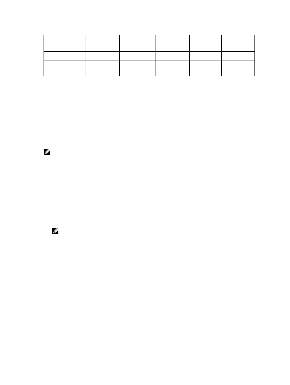
Feature PERC H330 PERC H730 PERC H730P PERC H830 PERC
PCIe Support Gen 3 Gen 3 Gen 3 Gen 3 Gen 3
FD33xD/
FD33xS
Non-RAID or pass
through mode
Yes Yes Yes Yes Yes
Management applications for PERC cards
Dell OpenManage Storage Management applications enable you to manage and configure the RAID
system, create and manage multiple disk groups, control and monitor multiple RAID systems, and provide
online maintenance. The management applications for PERC H730P include:
• Comprehensive Embedded Management
• Dell OpenManage Storage Management
• BIOS Configuration Utility (<Ctrl> <R>)
• Unified Extensible Firmware Interface (UEFI) RAID Configuration Utility
NOTE: Dell serial-attached SCSI (SAS) RAID Storage Manager is not supported for Self-Encrypting
Disks (SED) management.
Comprehensive embedded management
Comprehensive Embedded Management (CEM) is a storage management solution for Dell systems that
enables you to effectively monitor the RAID and network controllers installed on the system using iDRAC
without an OS installed on the system.
Using CEM enables you to perform the following:
• Monitor devices without an OS installed on the system.
• Provide a specific location to access monitored data of the storage devices and network cards.
• Allows controller configuration for all the PERC 9 cards (H330, H730, H730P, and H830).
NOTE:
The Comprehensive Embedded Management (CEM) feature is not supported on the Dell PowerEdge
R920 servers.
Dell OpenManage Storage Management
The Dell OpenManage Storage Management is a storage management application for Dell systems that
provides enhanced features for configuring a system's locally-attached RAID and Non-RAID disk storage.
The Dell OpenManage storage management application enables you to perform controller and enclosure
functions for all supported RAID controllers and enclosures from a single graphical or command-line
interface without using of the controller BIOS utilities. The graphical user interface (GUI) is wizard-driven
with features for novice and advanced users, and detailed online help. Using the Dell OpenManage
storage management application, you can protect your data by configuring data-redundancy, assigning
hot spares, or rebuilding failed physical disks. The command line interface available on selected operating
systems to perform RAID management tasks is fully featured and scriptable.
17
Page 18

NOTE: For more information, see the Dell OpenManage Storage Management User's Guide at
dell.com/openmanagemanuals.
Related documentation
NOTE:
• For all storage controllers and PCIe SSD documents, go to dell.com/storagecontrollermanuals.
• For all Dell OpenManage documents, go to dell.com/openmanagemanuals.
• For all operating system documents, go to dell.com/operatingsystemmanuals.
• For all PowerEdge documentation, go to dell.com/poweredgemanuals.
• For all PowerVault documentation, go to dell.com/powervaultmanuals.
18
Page 19

2
Getting started with your PERC card
The workflows outlined below list the procedures to getting started with the PERC card, based on your
system configuration:
• Installing the operating system and the PERC card on a base system
• Installing the PERC card on a system with the operating system pre-installed
• Installing the operating system on a system with the PERC card pre-installed
• Setting up the system with the PERC card and the operating system pre-installed
• Configuring settings of a replaced PERC card on a system with operating system pre-installed
Installing the operating system and the PERC card on a base system
1. Install the PERC 9 card in the system. For more information, see Deploying the PERC card.
2. Download the PERC 9 drivers from the Dell support site. For more information, see dell.com/
support.
3. Use any of the PERC management applications to create the virtual disks and RAID configurations
you require using the procedures listed below:
a. Importing Or Clearing Secured Foreign Configurations And Secure Disk Migration
b. Managing physical disks
1. Creating Global Hot Spares
2. Creating Security Key
3. Converting a RAID disk to a Non-RAID disk. For more information, see Controller
management.
4. Converting a Non-RAID disk to a RAID disk. For more information, see Controller
management.
c. Creating virtual disks
d. Managing virtual disks
1. Setting up virtual disks
2. Checking Data Consistency
3. Managing Preserved Cache
4. Initializing virtual disks
19
Page 20

5. Performing Background Initialization
6. Creating Secured Virtual Disks
7. Securing Pre-Existing Virtual Disks
e. Managing controllers through BIOS
1. Enabling Boot Support
2. Enabling Boot Support For A BIOS-Enabled Controller
3. Enabling BIOS Stop On Error
4. Enabling Auto Import
4. Install the operating system. For more information, refer to your operating system documentation.
5. Install the operating system drivers for PERC 9.
• If your operating system is Windows, install the Windows drivers. For more information, see
Windows driver installation.
• If your operating system is Linux, install the Linux drivers. For more information, see Linux driver
installation.
6. Additionally, you can install and use OpenManage Storage Services to manage the PERC card(s),
after the operating system is installed.
Installing the PERC card on a system with the operating system pre-installed
1. Install the PERC 9 card in the system. For more information, see Deploying the PERC card.
2. Download the PERC 9 drivers from the Dell support site. For more information, see dell.com/
support.
3. Install the operating system drivers for PERC 9.
• If your operating system is Windows, install the Windows drivers. For more information, see
Windows driver installation.
• If your operating system is Linux, install the Linux drivers. For more information, see Linux driver
installation.
4. Use any of the PERC management applications to create the virtual disks and RAID configurations
you require using the procedures listed below:
a. Importing Or Clearing Secured Foreign Configurations And Secure Disk Migration
b. Managing physical disks
1. Creating Global Hot Spares
2. Creating Security Key
3. Converting a RAID disk to a Non-RAID disk. For more information, see Controller
management.
4. Converting a Non-RAID disk to a RAID disk. For more information, see Controller
management.
20
Page 21

c. Creating virtual disks
• Setting up virtual disks
d. Managing virtual disks
1. Setting up virtual disks
2. Checking Data Consistency
3. Managing Preserved Cache
4. Initializing virtual disks
5. Performing Background Initialization
6. Creating Secured Virtual Disks
7. Securing Pre-Existing Virtual Disks
e. Managing Controllers through BIOS
1. Enabling Boot Support
2. Enabling Boot Support For A BIOS-Enabled Controller
3. Enabling BIOS Stop On Error
4. Enabling Auto Import
5. Additionally, you can install and use OpenManage Storage Services to manage the PERC card(s).
Installing the operating system on a system with the PERC card pre-installed
1. Use any of the PERC management applications to manage the virtual disks and RAID configurations
on your system, using the procedures listed below:
a. Importing Or Clearing Secured Foreign Configurations And Secure Disk Migration
b. Managing physical disks
1. Creating Global Hot Spares
2. Creating Security Key
3. Converting a RAID disk to a Non-RAID disk. For more information, see Controller
management.
4. Converting a Non-RAID disk to a RAID disk. For more information, see Controller
management.
c. Creating virtual disks
• Setting up virtual disks
d. Managing virtual disks
1. Setting up virtual disks
2. Checking Data Consistency
3. Managing Preserved Cache
21
Page 22

4. Initializing virtual disks
5. Performing Background Initialization
6. Creating Secured Virtual Disks
7. Securing Pre-Existing Virtual Disks
e. Managing Controllers through BIOS
1. Enabling Boot Support
2. Enabling Boot Support For A BIOS-Enabled Controller
3. Enabling BIOS Stop On Error
4. Enabling Auto Import
2. Install the operating system. For more information, refer to your operating system documentation.
3. Install the operating system drivers for PERC 9.
• If your operating system is Windows, install the Windows drivers. For more information, see
Windows driver installation.
• If your operating system is Linux, install the Linux drivers. For more information, see Linux driver
installation.
4. Additionally, you can install and use OpenManage Storage Services to manage the PERC card(s),
after the operating system is installed.
Setting up the system with the PERC card and the operating system pre-installed
1. Use any of the PERC management applications to create the virtual disks and RAID configurations
you require using the procedures listed below:
a. Importing Or Clearing Secured Foreign Configurations And Secure Disk Migration
b. Manage physical disks.
1. Creating Global Hot Spares
2. Creating Security Key
3. Converting a RAID disk to a Non-RAID disk. For more information, see Controller
management.
4. Converting a Non-RAID disk to a RAID disk. For more information, see Controller
management.
c. Creating virtual disks
• Setting up virtual disks
d. Managing virtual disks
1. Setting up virtual disks
2. Checking Data Consistency
3. Managing Preserved Cache
22
Page 23

4. Initializing virtual disks
5. Performing Background Initialization
6. Creating Secured Virtual Disks
7. Securing Pre-Existing Virtual Disks
e. Managing Controllers through BIOS
1. Enabling Boot Support
2. Enabling Boot Support For A BIOS-Enabled Controller
3. Enabling BIOS Stop On Error
4. Enabling Auto Import
2. Additionally, you can install and use OpenManage Storage Services to manage the PERC card(s).
Configuring settings of a replaced PERC card on a system with operating system pre-installed
1. Replace your existing PERC card with a new one and install the PERC 9 card in the system. For more
information, see Deploying the PERC card.
2. Download the PERC 9 drivers from the Dell support site. For more information, see dell.com/
support.
3. Use any of the PERC management applications to create the virtual disks and RAID configurations
you require using the procedures listed below:
a. Importing Or Clearing Secured Foreign Configurations And Secure Disk Migration
b. Managing physical disks
1. Creating Global Hot Spares
2. Creating Security Key
3. Converting a RAID disk to a Non-RAID disk. For more information, see Controller
management.
4. Converting a Non-RAID disk to a RAID disk. For more information, see Controller
management.
c. Creating virtual disks
• Setting up virtual disks
d. Managing virtual disks
1. Setting up virtual disks
2. Checking Data Consistency
3. Managing Preserved Cache
4. Initializing virtual disks
5. Performing Background Initialization
6. Creating Secured Virtual Disks
23
Page 24

7. Securing Pre-Existing Virtual Disks
e. Managing Controllers through BIOS
1. Enabling Boot Support
2. Enabling Boot Support For A BIOS-Enabled Controller
3. Enabling BIOS Stop On Error
4. Enabling Auto Import
4. Additionally, you can install and use OpenManage Storage Services to manage the PERC card(s).
24
Page 25

3
Features
PowerEdge RAID Controller (PERC) 9 series cards support the following features:
• Personality mode management
• T10 Protection Information (PI)
• secure firmware update
• improved RAID 10 configuration
• 4KB block size disk drives
PERC 9 personality management
PERC 9 series of cards support two personality modes.
• RAID mode: RAID mode is commonly used and the controllers are mostly shipped from the factory in
RAID mode. This mode allows the creation and operation of RAID virtual disks and non-RAID disks.
• HBA mode: In the HBA mode, PERC controller operates as Host Bus Adapter (HBA). This mode does
not contain virtual disks or the ability to create them. All physical disks function as non-RAID disks
under operating system control. The PERC card acts as a conduit between the host server and the
physical disks. Input and output requests originate from the host and are passed through the
controller to the physical drives. HBA mode is the approach used for Windows Storage Spaces.
NOTE: HBA mode should be enabled for customers, using Microsoft Storage Spaces or VMware
Virtual SAN. HBA mode allows the operating system to control backplane LED functionality on
supported systems.
T10 protection information
T10 Protection Information (PI) is an end-to-end data integrity feature of the PERC 9 series. When PI is
enabled, the PERC 9 series provides additional protection against silent data corruption, and ensures that
incomplete and incorrect data do not overwrite good data.
Only Dell certified PI disks are supported.
NOTE: PI is not supported on SAS disks with 512–byte native and 512–byte emulated block size and
SATA disks.
Enabling T10 PI
To enable T10 PI:
1. During host system boot, press <Ctrl> <R> to access the BIOs Configuration Utility.
25
Page 26
The Virtual Disk Management screen is displayed in the BIOS Configuration Utility window.
If there is more than one controller, the main menu screen is displayed. Select a controller, and press
<Enter>. The Virtual Disk Management screen is displayed for the selected controller.
2. Use the arrow keys to highlight the PERC 9 series of cards or Disk Group # .
NOTE: The H330 PERC card does not support the T10 PI feature.
3. Press <F2>.
The list of available actions is displayed.
4. Click Enable Data Protection.
Disabling T10 PI
To disable T10 PI:
1. Press <F2>.
The list of available actions is displayed.
2. Click Disable Data Protection.
Secure firmware update
This feature provides a cryptographic method of updating the firmware using RSA encryption-decryption
algorithm.
Only Dell certified firmware is supported on your PERC controller.
Improved RAID 10 configuration
RAID 10 configuration has been simplified for easier management and deployment. Disks are selected in
mirrored pairs.
NOTE: An even number of drives is required to create RAID 10 virtual disks.
4KB block size disk drives
PERC H330, H730, H730P and H830 cards support 4KB block size disk drives, which enables you to
efficiently use the storage space.
NOTE: Mixing 512–byte native and 512–byte emulated drives in a virtual disk is allowed, but mixing
512–byte and 4KB native block size drives in a virtual disk is not allowed.
Physical disk power management
Physical disk power management is a power-saving feature of the PERC 9 series cards. The feature allows
disks to be spun down based on disk configuration and I/O activity. The feature is supported on all
rotating SAS and SATA disks and includes unconfigured, configured, and hot-spare disks. The physical
disk power management feature is disabled by default. The feature can be enabled in the Dell Open
Manage Storage Management application or Unified Extensible Firmware Interface (UEFI) RAID
Configuration utility. For more information, see the Dell OpenManage documentation at dell.com/
support/manuals.
26
Page 27
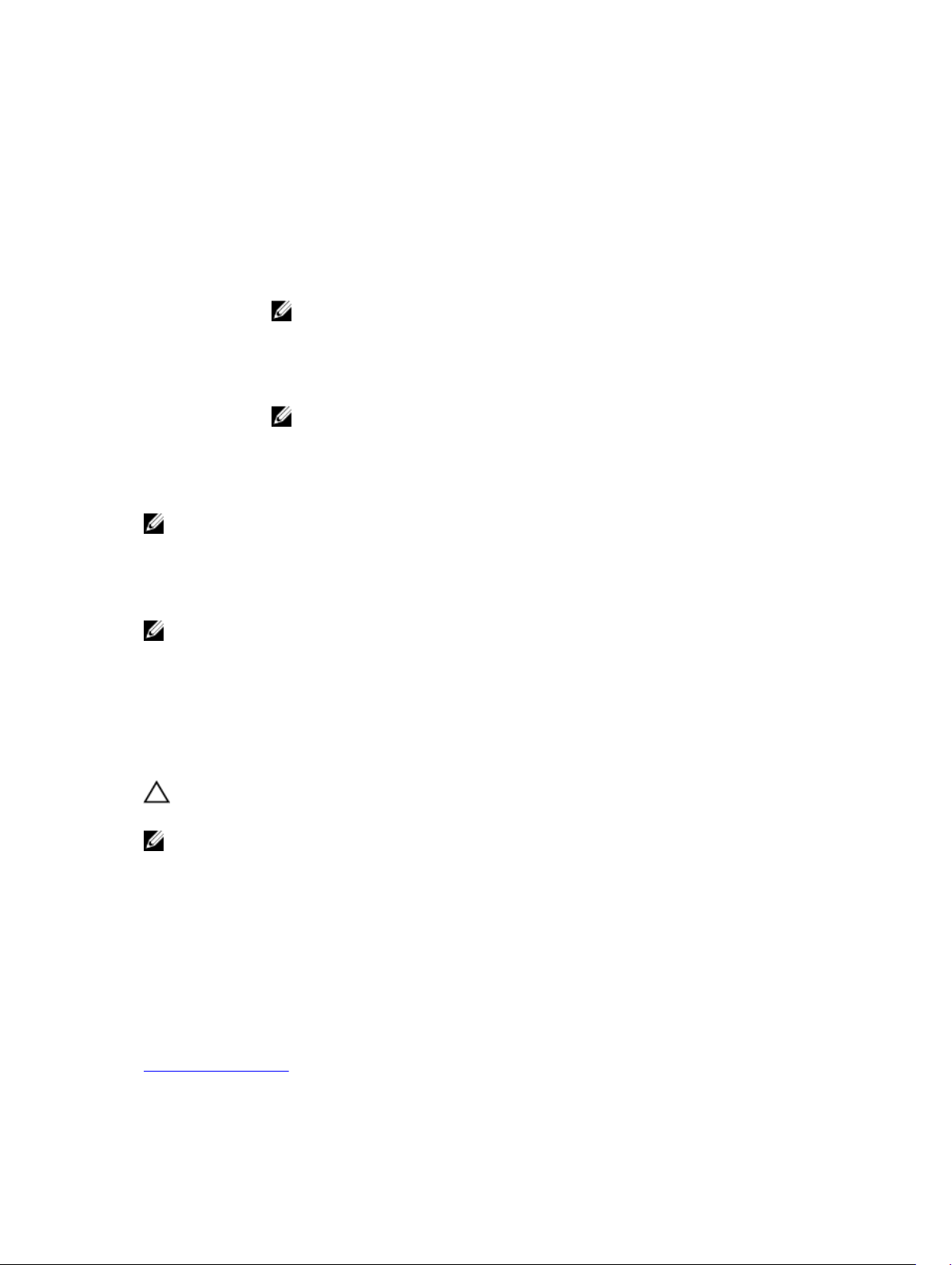
There are four power-saving modes:
No Power
Savings
(default mode)
Balanced
Power Savings
Maximum
Power Savings
Customized
Power Savings
All power savings features are disabled.
Spin down is enabled only for unconfigured and hot spare disks.
Spin down is enabled for configured, unconfigured, and hot spare disks.
NOTE: The maximum power savings mode is not supported by the H330
PERC card.
All power savings features are customizable. You can specify a Quality of Service
window during which the configured disks are excluded from spin-down.
NOTE: The customized power savings mode is not supported by the H330
PERC card.
Configured spin down delay
NOTE: The Configured Spin Down Delay option is not applicable for the No Power Savings mode.
The amount of time to wait before spinning down disks can be set using Configured Spin Down Delay.
The minimum value of the timer is 30 minutes (default) and the maximum is one day. Disks are spun
down automatically and spun up when accessed. All disks are spun up on reboot.
NOTE: There is a delay in I/O operations when a configured disk is being spun up.
Types of virtual disk initialization
PERC 9 series supports two types of virtual disk initialization:
• Full Initialization
• Fast Initialization
CAUTION: Initializing virtual disks erases files and file systems while keeping the virtual disk
configuration intact.
NOTE: The following initialization operations are not applicable for non-RAID disks.
Full initialization
Performing a full initialization on a virtual disk overwrites all blocks and destroys any data that previously
existed on the virtual disk. Full initialization of a virtual disk eliminates the need for the virtual disk to
undergo a Background initialization (BGI). Full initialization can be performed after the virtual disk is
created.
During full initialization, the host cannot access the virtual disk. You can start a full initialization on a
virtual disk by using the Slow Initialize option in the Dell OpenManage storage management application.
For more information on using the BIOS Configuration Utility to perform a full initialization, see
Initializing virtual disks.
27
Page 28

NOTE: For better performance, you can perform full initialization on virtual disks. Full initialization
does not support RAID 6 and RAID 60 virtual disks with the PI feature enabled. BGI runs instead.
NOTE: If the system reboots during a full initialization, the operation aborts and a BGI begins on the
virtual disk.
Fast initialization
A fast initialization on a virtual disk overwrites the first and last 8 MB of the virtual disk, clearing any boot
records or partition information. The operation takes only 2–3 seconds to complete, but it is followed by
BGI, which takes a longer time to complete. To perform a fast initialization using the BIOS Configuration
Utility, see Initializing virtual disks.
NOTE: Fast initialization does not support RAID 6 and RAID 60 virtual disks with the PI feature
enabled.
Background initialization
Background Initialization (BGI) is an automated process that writes the parity or mirror data on newly
created virtual disks. BGI does not run on RAID 0 virtual disks. You can control the BGI rate in the Dell
OpenManage storage management application. Any change in the BGI rate does not take effect until the
next BGI run.
NOTE: BGI will run on RAID 0 virtual disks only with PI enabled.
NOTE: You cannot disable BGI permanently. If you cancel BGI, it automatically restarts within five
minutes. For information on stopping BGI, see Stopping Background Initialization.
NOTE: Unlike full or fast initialization of virtual disks, background initialization does not clear data
from the physical disks.
NOTE: Consistency Check (CC)/BGI typically causes some loss in performance until the operation
completes.
NOTE: VD with PI will have a longer background initialization when compared to non-PI virtual
disks.
Consistency Check (CC) and BGI perform similar functions in that they both correct parity errors.
However, CC reports data inconsistencies through an event notification, but BGI does not. You can start
CC manually, but not BGI.
Consistency checks
Consistency Check (CC) is a background operation that verifies and corrects the mirror or parity data for
fault tolerant virtual disks. It is recommended that you periodically run a consistency check on virtual
disks.
You can manually start a CC using the BIOS Configuration Utility or the Dell OpenManage storage
management application. You can schedule a CC to run on virtual disks using the Dell OpenManage
storage management application. To start a CC using the BIOS Configuration Utility, see Checking Data
Consistency .
NOTE: CC/BGI typically causes some loss in performance until the operation completes.
28
Page 29
Consistency Check (CC) and BGI both correct parity errors. However, CC reports data inconsistencies
through an event notification, but BGI does not. You can start CC manually, but not BGI.
Disk roaming
Disk roaming is moving the physical disks from one cable connection or backplane slot to another on the
same controller. The controller automatically recognizes the relocated physical disks and logically places
them in the virtual disks that are part of the disk group. You can perform disk roaming only when the
system is turned off.
CAUTION: Do not attempt disk roaming during RAID level migration (RLM) or online capacity
expansion (OCE). This causes loss of the virtual disk.
Using disk roaming
Perform the following steps to use disk roaming:
1. Turn off the power to the system, physical disks, enclosures, and system components.
2. Disconnect power cables from the system.
3. Move the physical disks to desired positions on the backplane or the enclosure.
4. Perform a safety check. Make sure the physical disks are inserted properly.
5. Turn on the system.
The controller detects the RAID configuration from the configuration data on the physical disks.
FastPath
FastPath is a feature that improves application performance by delivering high I/O per second (IOPs) for
the Solid State Drives (SSD). The Dell PowerEdge RAID Controller (PERC) 9 series supports FastPath.
To enable FastPath on a virtual disk the Dell PowerEdge RAID Controller (PERC) 9 series cache policies
need to be set to Write-Through and No Read Ahead. This enables FastPath to use the proper data path
through the controller based on command (read/write), IO size, and RAID type.
For small random workloads, like OLTP, a RAID 10 array provides high performance and for sequential
read dominant workloads, a RAID5 array provides high performance.
NOTE: Only IO block sizes smaller than virtual disk’s stripe size are eligible for FastPath.
NOTE: The Physical Disk Power Management feature is not applicable to FastPath-capable virtual
disks.
Configuring FastPath-capable virtual disks
All simple virtual disks configured with write cache policy Write Through and read cache policy No Read
Ahead can utilize FastPath. Only IO block sizes smaller than virtual disk’s stripe size are eligible for
FastPath. In addition, there should be no background operations (rebuild, initialization) running on the
virtual disks. FastPath will not be used if these operations are active.
NOTE: RAID 50, and RAID 60 virtual disks cannot use FastPath.
29
Page 30
The following table summarizes the FastPath-eligibility of read and write IOs across the supported RAID
levels.
Table 1. FastPath eligibility across supported RAID levels
RAID 0 RAID 1 RAID 5 RAID 6 RAID 10
Read Yes
Write Yes No No No No
Yes
(Optimal and
Degraded)
Yes
(Optimal and
Degraded)
Yes
(Optimal and
Degraded)
Yes
(Optimal)
Virtual disk migration
The PERC 9 series supports migration of virtual disks from one controller to another without taking the
target controller offline. The controller can import RAID virtual disks in optimal, degraded, or partially
degraded states. You cannot import a virtual disk that is offline. Disk migration pointers:
• Supports migration of virtual disks from PERC H310, H710, H710P, and H810 to PERC 9 series
• Supports migration of volumes created within PERC 9 series
• Does not support migration from PERC 9 series to H310, H710, H710P, H810
NOTE: The source controller must be offline prior to performing the disk migration.
NOTE: Disks cannot be migrated to older generations of the PERC cards.
NOTE: Importing secured virtual disks is supported as long as the appropriate Local Key
Management (LKM) is supplied or configured.
When a controller detects a configured physical disk, it flags the physical disk as foreign, and generates
an alert indicating that a foreign disk was detected.
CAUTION: Do not attempt disk migration during RLM or online capacity expansion (OCE). This
causes loss of the virtual disk.
Migrating virtual disks
To migrate virtual disks from PERC H710, H710P, or H810 to PERC 9 series:
1. Turn off the system.
2. Ensure that all the latest firmware and drivers for the PERC H330, H730, H730P, or H830 card
(available at dell.com/support) are installed on the destination system.
For more information, see Driver installation.
3. Move the physical disks from PERC H310, H710, H710P, or H810 card to the PERC 9 series.
4. Boot the system and import the foreign configuration that is detected. You can do one of the
following:
• Press <F> to automatically import the foreign configuration.
• Enter the BIOS Configuration Utility and navigate to the Foreign Configuration View.
NOTE: For more information on accessing the BIOS Configuration Utility, see Entering the
BIOS configuration utility.
30
Page 31
NOTE: For more information on Foreign Configuration View, see Foriegn Configuration View.
5. Exit the BIOS Configuration Utility and reboot the system.
Virtual disk write cache policies
The write cache policy of a virtual disk determines how the controller handles writes to the virtual disk.
The write cache policies are:
Write-Back The controller sends a data transfer completion signal to the host when the
controller cache has received all the data in a transaction. The controller then
writes the cached data to the storage device in the background.
NOTE: The default cache setting for virtual disks is Write-Back caching.
Write-Through The controller sends a data transfer completion signal to the host system when the
disk subsystem has received all the data in a transaction.
All RAID volumes are presented as Write-Through to the operating system
(Windows and Linux) independent of the actual write cache policy of the virtual
disk. The PERC cards manage the data in cache independently of the operating
system or any applications.
NOTE: Certain data patterns and configurations perform better with a Write-
Through cache policy.
NOTE: Use the Dell OpenManage storage management application or the BIOS Configuration
Utility to view and manage virtual disk cache settings.
Conditions under which write-back is employed
Write-Back caching is used under all conditions in which the battery is present and in good condition.
Conditions under which forced write-back with no battery is employed
CAUTION: It is recommended that you use a power backup system when forcing Write-Back to
ensure there is no loss of data if the system suddenly loses power.
Write-Back mode is available when you select Force WB with no battery. When Forced Write-Back
mode is selected, the virtual disk is in Write-Back mode even if the battery is not present.
Virtual disk read cache policies
The read policy of a virtual disk determines how the controller handles reads to that virtual disk. The read
policies are:
Read Ahead Allows the controller to read sequentially ahead of requested data and to store the
additional data in cache memory, anticipating that the data is required soon. This
speeds up reads for sequential data, but there is little improvement when accessing
random data.
No Read Ahead Disables the Read-Ahead capability.
31
Page 32
Reconfiguration of virtual disks
An online virtual disk can be reconfigured in ways that expands its capacity and/or change its RAID level.
NOTE: Spanned virtual disks such as RAID 10, 50, and 60 cannot be reconfigured.
NOTE: Reconfiguring Virtual Disks typically impacts disk performance until the reconfiguration
operation is complete.
Online Capacity Expansion (OCE) can be done in two ways:
• If there is a single virtual disk in a disk group and free space is available, the virtual disk’s capacity can
be expanded within that free space.
• If a virtual disk is created and it does not use the maximum size of the disk group, free space is
available.
Free space is also available when a disk group’s physical disks are replaced by larger disks using the
Replace Member feature. A virtual disk's capacity can also be expanded by performing an OCE operation
to add more physical disks.
RAID Level Migration (RLM) refers to changing a virtual disk’s RAID level. Both RLM and OCE can be done
at the same time so that a virtual disk can simultaneously have its RAID level changed and its capacity
increased. When a RLM/OCE operation is complete, a reboot is not required. The source RAID level
column indicates the virtual disk RAID level before the RLM/OCE operation and the target RAID level
column indicates the RAID level after the RLM/OCE operation.
NOTE: If the controller already contains the maximum number of virtual disks, you cannot perform
a RAID level migration or capacity expansion on any virtual disk.
NOTE: The controller changes the write cache policy of all virtual disks undergoing a RLM/OCE
operation to Write-Through until the RLM/OCE operation is complete.
See the following table for a list of RLM/OCE possibilities.
Table 2. RAID level migration
Source RAID
Level
RAID 0 RAID 0 1 2 or more Yes Increases
RAID 0 RAID 1 1 2 No Converts a
RAID 0 RAID 5 1 or more 3 or more Yes At least one
Target RAID
Level
Number of
Physical Disks
(Beginning)
Number of
Physical Disks
(End)
Capacity
Expansion
Possible
Description
capacity by
adding disks.
non-redundant
virtual disk into
a mirrored
virtual disk by
adding one
disk.
disk needs to
be added for
32
Page 33

Source RAID
Level
RAID 0 RAID 6 1 or more 4 or more Yes At least two
RAID 1 RAID 0 2 2 or more Yes Removes
RAID 1 RAID 5 2 3 or more Yes Maintains
RAID 1 RAID 6 2 4 or more Yes Two disks
Target RAID
Level
Number of
Physical Disks
(Beginning)
Number of
Physical Disks
(End)
Capacity
Expansion
Possible
Description
distributed
parity data.
disks need to
be added for
dual distributed
parity data.
redundancy
while increasing
capacity.
redundancy
while doubling
capacity.
required to be
added for
distributed
parity data.
RAID 5 RAID 0 3 or more 3 or more Yes Converts to a
non-redundant
virtual disk and
reclaims disk
space used for
distributed
parity data.
RAID 5 RAID 5 3 or more 4 or more Yes Increases
capacity by
adding disks.
RAID 5 RAID 6 3 or more 4 or more Yes At least one
disk needs to
be added for
dual distributed
parity data.
RAID 6 RAID 0 4 or more 4 or more Yes Converts to a
non-redundant
virtual disk and
reclaims disk
space used for
distributed
parity data.
33
Page 34

Source RAID
Level
RAID 6 RAID 5 4 or more 4 or more Yes Removes one
RAID 6 RAID 6 4 or more 5 or more Yes Increases
NOTE: The total number of physical disks in a disk group cannot exceed 32. You cannot perform
RAID level migration and expansion on RAID levels 10, 50, and 60.
Target RAID
Level
Number of
Physical Disks
(Beginning)
Number of
Physical Disks
(End)
Capacity
Expansion
Possible
Description
set of parity
data and
reclaims disk
space used for
it.
capacity by
adding disks
Fault tolerance
The PERC 9 series supports the following:
• Self Monitoring and Reporting Technology (SMART)
• Patrol Read
• Physical disk failure detection
• Physical disk rebuild using hot spares
• Controller cache preservation
• Battery and non-volatile cache backup of controller cache to protect data
• Detection of batteries with low charge after boot up
The next sections describe some methods to achieve fault tolerance.
The SMART Feature
The SMART feature monitors certain physical aspects of all motors, heads, and physical disk electronics
to help detect predictable physical disk failures. Data on SMART-compliant physical disks can be
monitored to identify changes in values and determine whether the values are within threshold limits.
Many mechanical and electrical failures display some degradation in performance before failure.
A SMART failure is also referred to as predicted failure. There are numerous factors that are predicted
physical disk failures, such as a bearing failure, a broken read/write head, and changes in spin-up rate. In
addition, there are factors related to read/write surface failure, such as seek error rate and excessive bad
sectors.
NOTE: For detailed information on SCSI interface specifications, see t10.org and for detailed
information on SATA interface specifications, see t13.org.
Automatic replace member with predicted failure
A Replace Member operation can occur when there is a SMART predictive failure reporting on a physical
disk in a virtual disk. The automatic Replace Member is initiated when the first SMART error occurs on a
physical disk that is part of a virtual disk. The target disk needs to be a hot spare that qualifies as a rebuild
34
Page 35

disk. The physical disk with the SMART error is marked as failed only after the successful completion of
the Replace Member. This prevents the array from reaching degraded state.
If an automatic Replace Member occurs using a source disk that was originally a hot spare (that was used
in a rebuild), and a new disk added for the Replace Member operation as the target disk, the hot spare
reverts to the hot spare state after a successful Replace Member operation.
NOTE: To enable the automatic Replace Member, use the Dell OpenManage storage management
application. For information on manual Replace Member, see Replacing An Online Physical Disks.
Patrol Read
The Patrol Read feature is designed as a preventative measure to ensure physical disk health and data
integrity. Patrol Read scans and resolves potential problems on configured physical disks. The Dell
OpenManage storage management application can be used to start Patrol Read and change its behavior.
The following is an overview of Patrol Read behavior:
• Patrol Read runs on all disks on the controller that are configured as part of a virtual disk, including
hot spares.
• Patrol Read does not run on physical disks that are not part of a virtual disk or are in Ready state.
• Patrol Read adjusts the amount of controller resources dedicated to Patrol Read operations based on
outstanding disk I/O. For example, if the system is busy processing I/O operation, then Patrol Read
uses fewer resources to allow the I/O to take a higher priority.
• Patrol Read does not run on any disks involved in any of the following operations:
– Rebuild
– Replace Member
– Full or Background Initialization
– CC
– RLM or OCE
NOTE: By default, Patrol Read automatically runs every seven days on configured SAS and SATA
hard drives. Patrol Read is not necessary on SSD and is disabled by default.
For more information on Patrol Read, see the Dell OpenManage documentation at dell.com/support/
manuals.
Physical disk failure detection
Failed physical disks are detected and rebuilds automatically start to new disks that are inserted into the
same slot. Automatic rebuilds can also occur with hot spares. If you have configured hot spares, the
controllers automatically try to use them to rebuild failed physical disks.
Using persistent hot spare slots
NOTE: The persistent hot spare slot feature is disabled by default.
The PERC 9 series can be configured so that the system backplane or storage enclosure disk slots are
dedicated as hot spare slots. This feature can be enabled using the Dell OpenManage storage
management application.
Once enabled, any slots with hot spares configured automatically become persistent hot spare slots. If a
hot spare disk fails or is removed, a replacement disk that is inserted into the same slot automatically
35
Page 36

becomes a hot spare with the same properties as the one it is replacing. If the replacement disk does not
match the disk protocol and technology, it does not become a hot spare.
For more information on persistent hot spares, see the Dell OpenManage documentation at dell.com/
support/manuals.
Physical disk hot swapping
NOTE: To check if the backplane supports hot swapping, see the Owner’s Manual of your system.
Hot swapping is the manual replacement of a disk while the PERC 9 series cards are online and
performing their normal functions. The following requirements must be met before hot swapping a
physical disk:
• The system backplane or enclosure must support hot swapping for the PERC 9 series cards to support
hot swapping.
• The replacement disk must be of the same protocol and disk technology. For example, only a SAS
hard drive can replace a SAS hard drive and only a SATA SSD can replace a SATA SSD.
Using replace member and revertible hot spares
The Replace Member functionality allows a previously commissioned hot spare to revert to a usable hot
spare. When a disk failure occurs within a virtual disk, an assigned hot spare (dedicated or global) is
commissioned and begins rebuilding until the virtual disk is optimal. After the failed disk is replaced (in the
same slot) and the rebuild to the hot spare is complete, the controller automatically starts to copy data
from the commissioned hot spare to the newly-inserted disk. After the data is copied, the new disk is a
part of the virtual disk and the hot spare is reverted to being a ready hot spare. This allows hot spares to
remain in specific enclosure slots. While the controller is reverting the hot spare, the virtual disk remains
optimal.
NOTE: The controller automatically reverts a hot spare only if the failed disk is replaced with a new
disk in the same slot. If the new disk is not placed in the same slot, a manual Replace Member
operation can be used to revert a previously commissioned hot spare.
NOTE: A Replace Member operation typically causes a temporary impact to disk performance.
Once the operation completes, performance returns to normal.
Controller cache preservation
The controller is capable of preserving its cache in the event of a system power outage or improper
system shutdown. The PERC 9 Series controller is attached to a Battery Backup Unit (BBU) that provides
backup power during system power loss to preserve the controller's cache data.
Cache Preservation With NVC
The Non-Volatile Cache (NVC) allows controller cache data to be stored indefinitely. If the controller has
data in the cache memory during a power outage or improper system shutdown, a small amount of
power from the battery is used to transfer the cache data to a non-volatile flash storage where it remains
until power is restored and the system is booted.
36
Page 37

Recovering cache data
If a system power loss or improper system shutdown has occurred:
1. Restore the system power.
2. Boot the system.
3. To enter the BIOS Configuration Utility, select Managed Preserved Cache in the controller menu.
For more information, see Entering the BIOS configuration utility.
If there are no virtual disks listed, all preserved cache data has been written to the disk successfully.
Battery Transparent Learn Cycle
A transparent learn cycle is a periodic operation that calculates the charge that is remaining in the battery
to ensure there is sufficient energy. The operation runs automatically, and causes no impact to the
system or controller performance.
The controller automatically performs the Transparent Learn Cycle (TLC) on the battery to calibrate and
gauge its charge capacity once every 90 days. The operation can be performed manually, if required.
NOTE: Virtual disks stay in Write Back mode, if enabled, during transparent learn cycle. When the
TLC completes, the controller sets the next TLC to +90 days.
TLC time frame
The time frame for completion of a learn cycle is a function of the battery charge capacity and the
discharge and charge currents used.
Conditions for replacing the battery
The PERC battery is marked Failed when the state or health of the battery is declared bad. If battery is
declared failed then the firmware runs learn cycles in subsequent reboots until the battery is replaced.
The virtual disk then transitions to Write Back mode.
Non-RAID disks support
By default, all the disks are in RAID capable unconfigured state. The user can also convert the RAID
capable disks to non-RAID disks using either the BIOS configuration utility or the UEFI/HII RAID
configuration utility.
Creating a non-raid disk
To create a non-RAID disk, perform the following steps in the BIOS Configuration Utility (<Ctrl> <R>):
1. In the Virtual Disk Mgmnt screen, use the arrow keys to highlight the PERC 9 adapter or Disk Group
#.
2. Press <F2>.
The list of available action is displayed.
3. Click Convert to Non-RAID.
The Convert RAID Capable Disks to Non-RAID window is displayed.
4. Press the down-arrow key to highlight an available physical disk.
5. Press the spacebar to select the disk.
37
Page 38

NOTE: An X is displayed beside the selected physical disk(s).
6. Select OK.
38
Page 39
Deploying the PERC card
CAUTION: Many repairs may only be done by a certified service technician. You should only
perform troubleshooting and simple repairs as authorized in your product documentation, or as
directed by the online or telephone service and support team. Damage due to servicing that is
not authorized by Dell is not covered by your warranty. Read and follow the safety instructions
that came with the system.
This document provides a set of high-level installation and removal instructions for the following Dell
PowerEdge RAID Controllers (PERC) 9 series:
1. PERC H330 Adapter
2. PERC H330 Mini Monolithic
3. PERC H330 Slim Card
4. PERC H330 Mini Blade
5. PERC H730 Adapter
6. PERC H730 Mini Monolithic
7. PERC H730 Slim Card
8. PERC H730 Mini Blade
9. PERC H730P Adapter
10. PERC H730P Mini Monolithic
11. PERC H730P Slim Card
12. PERC H730P Mini Blade
13. PERC H830 Adapter
14. PERC FD33xS Card
15. PERC FD33xD Card
4
NOTE: For detailed information on cabling the PERC 9 cards, see the system documentation at
dell.com/poweredgemanuals.
Removing the PERC 9 adapter
CAUTION: Many repairs may only be done by a certified service technician. You should only
perform troubleshooting and simple repairs as authorized in your product documentation, or as
directed by the online or telephone service and support team. Damage due to servicing that is
not authorized by Dell is not covered by your warranty. Read and follow the safety instructions
that came with the product.
1. Turn off the system, including any attached peripherals, and disconnect the system from the
electrical outlet and peripherals.
39
Page 40
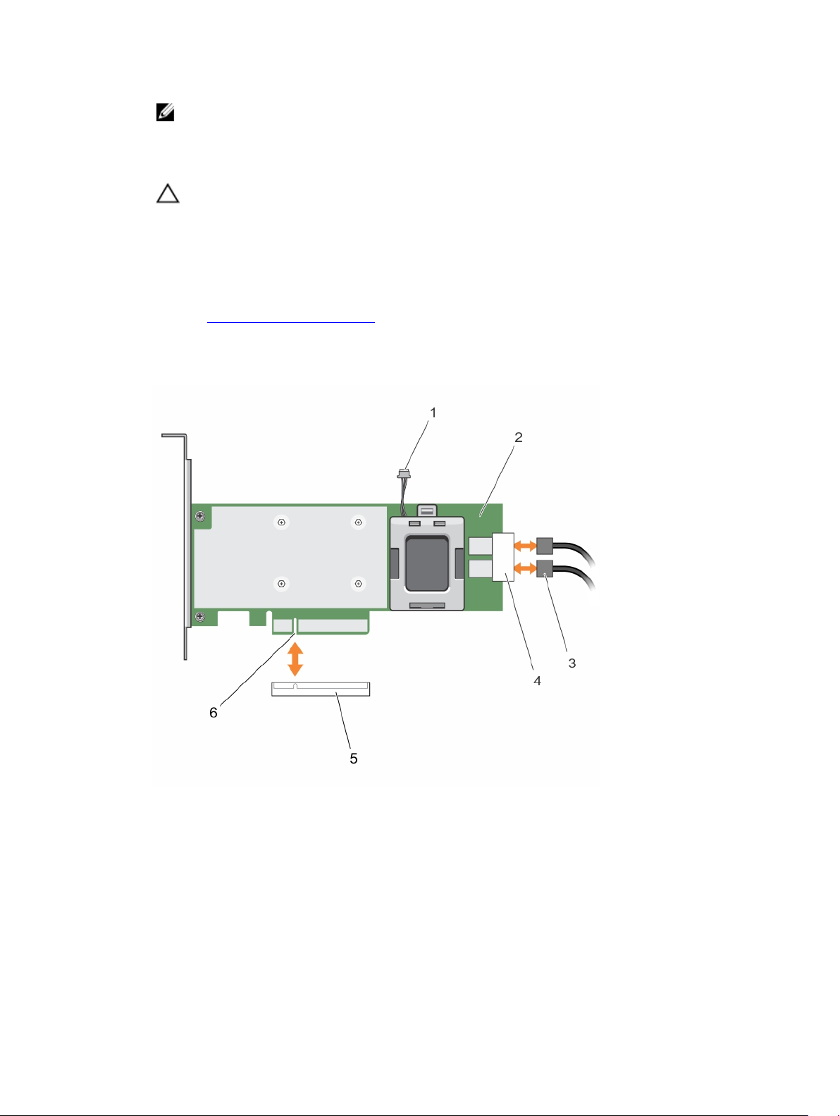
NOTE: It is recommended that you always use a static mat and static strap while working on
components in the interior of the system.
2. Open the system.
3. Locate the PERC card on the system board.
CAUTION: To prevent damage to the card, you must hold the card by its edges only.
4. Lift the card to remove it from the connector on the system board.
5. Disconnect the SAS cables connected to the card:
a. Press down and hold the metal tab on the SAS cable connector.
b. Pull the SAS cable out of the connector.
6. Replace the storage controller card and connect the cable. For more information on installing the
card, see Installing the PERC 9 adapter.
7. Close the system.
8. Reconnect the system to its electrical outlet and turn the system on, including any attached
peripherals.
Figure 7. Removing and installing the PERC 9 card
1. battery cable connector 2. PERC 9 card
3. SAS cables (2) 4. SAS cable connectors (2)
5. card connector on the system board 6. PERC card connector
40
Page 41
Installing the PERC 9 adapter
CAUTION: Many repairs may only be done by a certified service technician. You should only
perform troubleshooting and simple repairs as authorized in your product documentation, or as
directed by the online or telephone service and support team. Damage due to servicing that is
not authorized by Dell is not covered by your warranty. Read and follow the safety instructions
that came with the product.
1. Turn off the system, including any attached peripherals, and disconnect the system from the
electrical outlet.
NOTE: It is recommended that you always use a static mat and static strap while working on
components in the interior of the system.
2. Open the system.
3. Align the card-edge connector with the connector on the system board.
To prevent damage to the card, you must hold the card by its edges only.
4. Press the card-edge down until the card is fully seated.
5. Align the PERC card connector with the card connector on the system board and push the PERC
card towards the connector to seat it firmly.
6. Connect the SAS data cable connectors to the card.
NOTE: Ensure that you connect the cable according to the connector labels on the cable. The
cable does not function properly if reversed.
7. Route the SAS data cable through the clip on the card and through the channel on the inner side of
the chassis.
8. Attach the connector labeled "SAS A" to connector SAS A on the backplane, and attach the
connector labeled "SAS B" to connector SAS B on the backplane.
9. Close the system.
10. Reconnect the system to its electrical outlet and turn the system on, including any attached
peripherals.
Removing the PERC 9 mini monolithic controller
CAUTION: Many repairs may only be done by a certified service technician. You should only
perform troubleshooting and simple repairs as authorized in your product documentation, or as
directed by the online or telephone service and support team. Damage due to servicing that is
not authorized by Dell is not covered by your warranty. Read and follow the safety instructions
that came with the product.
1. Turn off the system, including any attached peripherals, and disconnect the system from the
electrical outlet and peripherals.
NOTE: It is recommended that you always use a static mat and static strap while working on
components in the interior of the system.
2. Open the system.
3. Locate the PERC card on the system board
4. To disconnect the storage controller cable:
a. Remove the two screws that secure the cable to the card.
41
Page 42
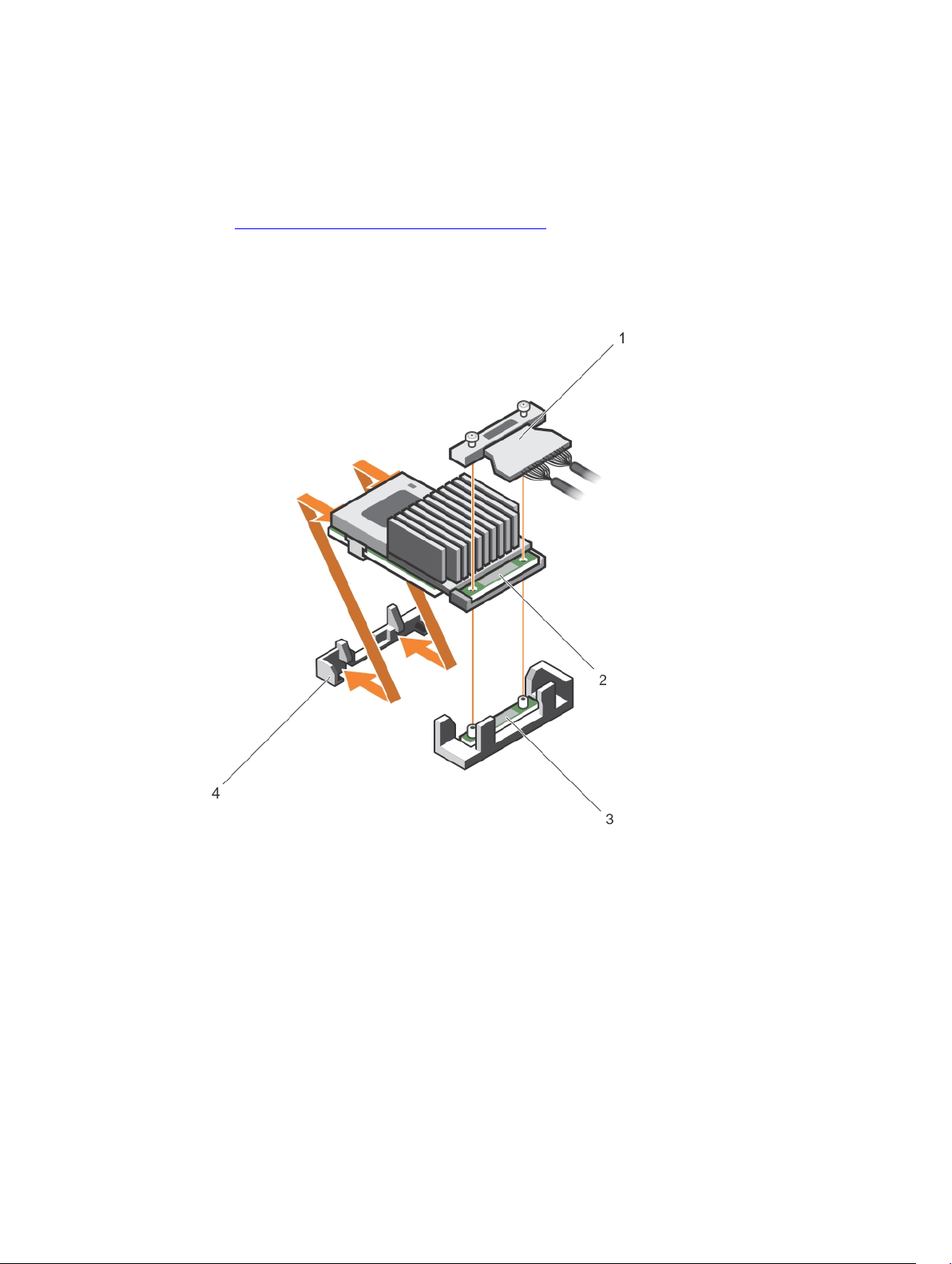
b. Grasp the cable on both sides of the cable connector, and pull the cable up and away from the
PERC card.
5. Angle the card so that the other end of the card disengages from the storage-controller card holder
on the system board.
6. Replace the storage controller card and connect the cable. For more information on installing the
card, see Installing the PERC 9 mini monolithic controller.
7. Close the system.
8. Reconnect the system to its electrical outlet and turn the system on, including any attached
peripherals.
Figure 8. Removing and installing the PERC 9 mini monolithic card
1. storage controller cable 2. storage controller card
3. storage-controller card holder 4. storage controller retention hook
Replacing the battery of a H730P mini monolithic card
1. Turn off the system, including any attached peripherals, and disconnect the system from the
electrical outlet and peripherals.
42
Page 43
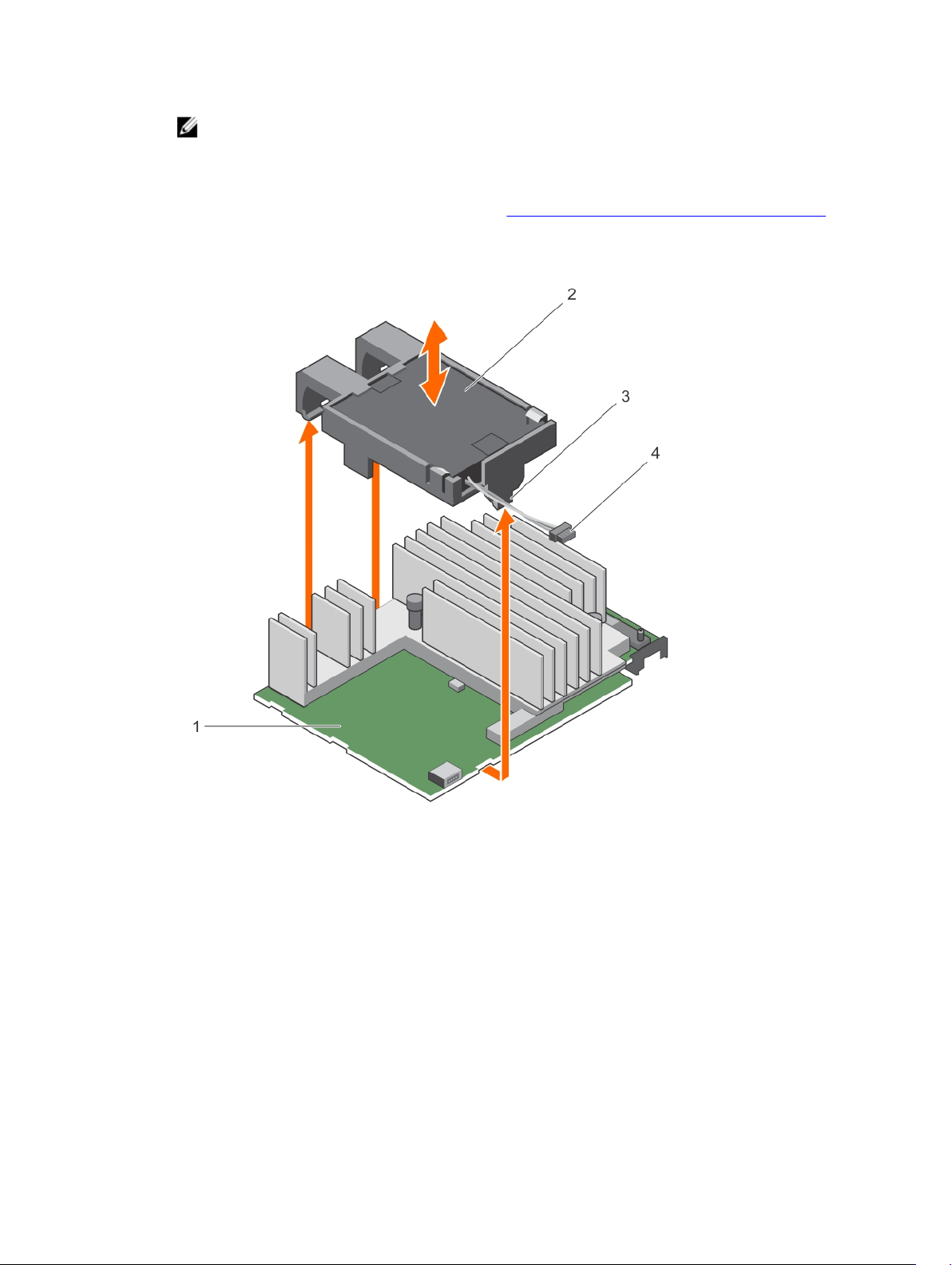
NOTE: It is recommended that you always use a static mat and static strap while working on
components in the interior of the system.
2. Open the system.
3. Locate the PERC card on the system board.
4. Remove the PERC card. For more information, see Removing the PERC 9 mini monolithic controller.
5. Disconnect the battery cable from the PERC card.
6. Pull the battery carrier until the tabs on the battery carrier disengage from the PERC card.
Figure 9. Removing the battery carrier
1. PECR H730P mini monolithic card 2. battery
3. tab on the battery carrier (3) 4. battery cable
7. Pull the battery out of the battery carrier.
43
Page 44
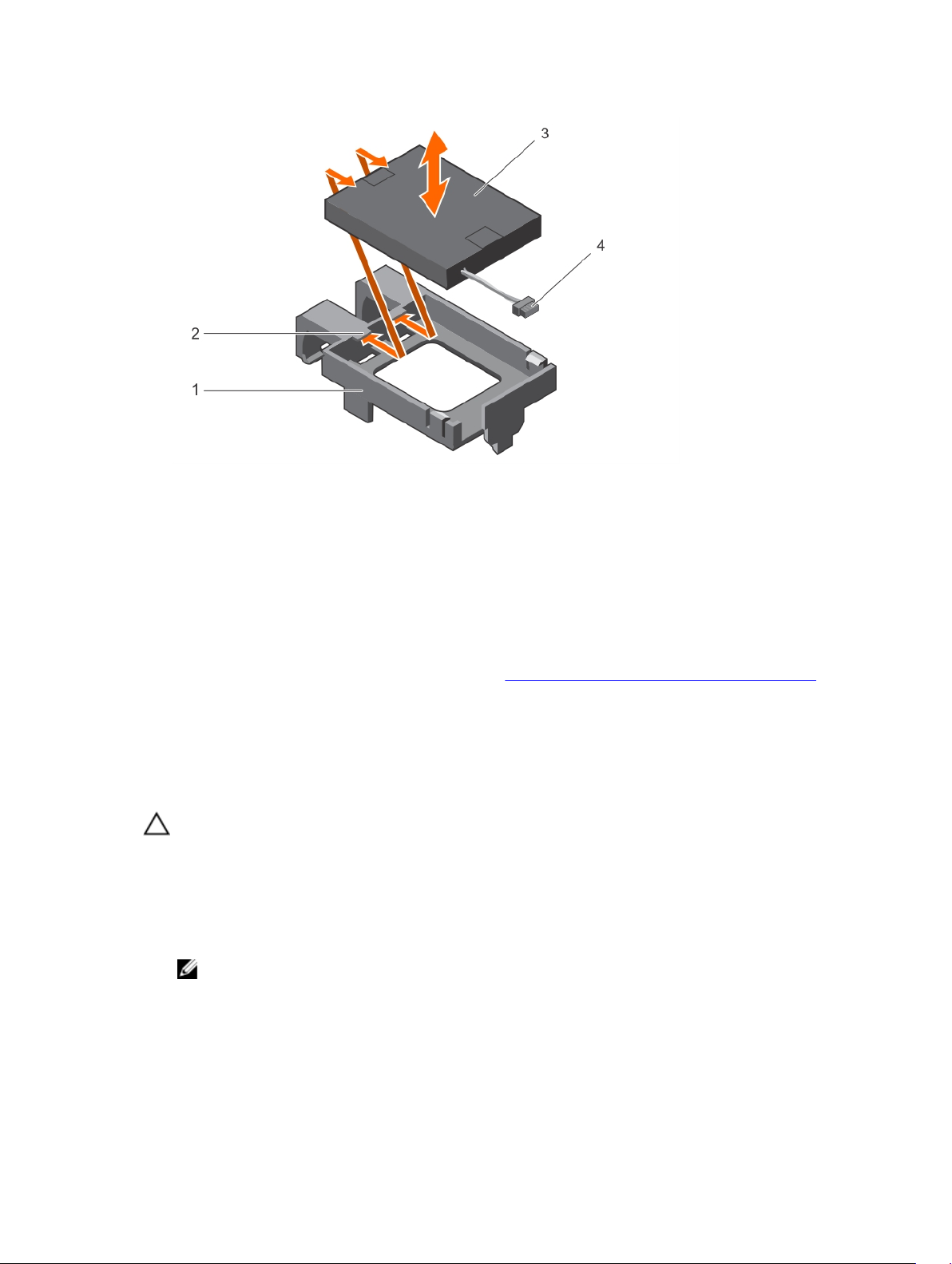
Figure 10. Removing the battery
1. battery carrier 2. guide on the battery carrier (2)
3. battery 4. battery cable
8. Align the replacement battery with the guides on the battery carrier.
9. Lower the battery into the carrier until the battery clicks into place.
10. Align the tabs on the battery carrier with the slots on the PERC9 mini monolithic controller and lower
the battery carrier till it clicks into place.
11. Connect the battery cable to the PERC card.
12. Replace the PERC card. For more information, see Installing the PERC 9 mini monolithic controller.
13. Close the system.
14. Reconnect the system to its electrical outlet and turn on the system, including any attached
peripherals.
Installing the PERC 9 mini monolithic controller
CAUTION: Many repairs may only be done by a certified service technician. You should only
perform troubleshooting and simple repairs as authorized in your product documentation, or as
directed by the online or telephone service and support team. Damage due to servicing that is
not authorized by Dell is not covered by your warranty. Read and follow the safety instructions
that came with the product.
1. Turn off the system, including any attached peripherals, and disconnect the system from the
electrical outlet.
NOTE: It is recommended that you always use a static mat and static strap while working on
components in the interior of the system.
2. Open the system.
3. Locate the PERC 9 card connector on the system board and align one end of the card with the card
holder on the system board.
44
Page 45
CAUTION: To prevent damage to the card, you must hold the card by its edges only.
4. Lower the other end of the card into the card holder on the system board.
5. Connect the storage controller cable:
a. Grasp the cable on both sides of the cable connector and connect to the PERC card.
b. Attach the two screws to secure the cable to the card.
6. Connect the SAS data cable connector to the card.
NOTE: Ensure that you connect the cable according to the connector labels on the cable. The
cable does not function properly if reversed.
7. Route the SAS data cable through the clip on the card and through the channel on the inner side of
the chassis.
8. Attach the connector labeled "SAS A" to connector SAS A on the backplane, and attach the
connector labeled "SAS B" to connector SAS B on the backplane.
9. Close the system.
10. Reconnect the system to its electrical outlet and turn the system on, including any attached
peripherals.
Removing a H730P slim card
1. Turn off the system, including any attached peripherals, and disconnect the system from the
electrical outlet and peripherals.
NOTE: It is recommended that you always use a static mat and static strap while working on
components in the interior of the system.
2. Open the system.
3. Locate the H730P slim card on the system board.
4. Loosen the two retention screws on the H730P slim card cable connector.
5. Holding the pull tag, lift the H730P slim card cable connector from the system board connector.
6. Press the release latch on the side of the chassis to the unlock position and slide the H730P slim card
toward the back of the system.
CAUTION: To prevent damage to the H730P slim card, you must hold the card only by its
edges.
7. Lift the card up and away from the system.
8. Replace the storage controller card and connect the cable. For more information on installing the
card, see
Installing a H730P Slim card.
45
Page 46

Figure 11. Removing and installing a H730P slim card
1. standoff (2) 2. H730P slim card cable connector
3. pull tag 4. H730P slim card
5. H730P slim card release latch 6. lock and unlock icon on the H730P slim
card bracket
Replacing the battery of a H730P slim card
The battery attached to the H730P slim card can be replaced.
1. Turn off the system, including any attached peripherals, and disconnect the system from the
electrical outlet and peripherals.
NOTE: It is recommended that you always use a static mat and static strap while working on
components in the interior of the system.
2. Open the system.
3. Locate the H730P slim card on the system board.
4. Remove the H730P slim card. For more information, see Removing a H730P Slim card.
5. Remove the screw that secures the battery along with the flexible cable retainer to the H730P slim
card.
6. Remove the clamp that secures the battery along with the flexible cable retainer to the H730P slim
card.
46
Page 47
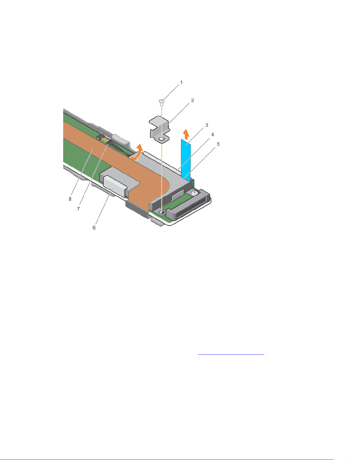
7. Pull the blue tab to an upright position, until the top of the battery is out of the battery holder on the
H730P slim card.
8. Disconnect the battery cable from the H730P slim card.
9. Lift the battery out of the battery holder.
Figure 12. Removing the battery
1. screw securing the battery to the H730P
slim card
2. clamp securing the battery to the
H730P slim card
3. tab 4. H730P slim card
5. battery 6. battery holder
7. battery cable 8. flexible cable retainer
10. Insert the battery into the battery holder.
11. Push the blue tab toward the inserted battery.
12. Attach the clamp that secures the battery along with the flexible cable retainer to the H730P slim
card.
13. Attach the screw that secures the battery along with the flexible cable retainer to the H730P slim
card.
14. Connect the battery cable to the H730P slim card.
15. Replace the H730P slim card. For more information, see Installing a H730P Slim card.
16. Close the system.
17. Reconnect the system to its electrical outlet and turn on the system, including any attached
peripherals.
47
Page 48

Installing a H730P slim card
1. Turn off the system, including any attached peripherals, and disconnect the system from the
electrical outlet.
NOTE: It is recommended that you always use a static mat and static strap while working on
components in the interior of the system.
2. Open the system.
3. Press the release latch on the side of the chassis to the unlock position.
4. Align the slots on the H730P slim card with the standoffs on the side of the chassis.
CAUTION: To prevent damage to the system memory, ensure that the H730P slim card does
not come in contact with the memory modules during installation
5. Lower the H730P slim card into the chassis until the slots on the card engage with the standoffs on
the side of the chassis.
6. Press the release latch to the lock position to secure the card firmly on the chassis.
The H730P slim card connects to the backplane connector.
7. Hold the pull tag on the H730P slim card cable connector and route the cable between the memory-
module ejectors.
8. Align the retention screws on the H730P slim card cable connector with the screw holes on the
system board connector.
9. Tighten the two retention screws to secure the H730P slim card cable connector on the system
board.
Removing the PERC 9 mini blade controller
1. Turn off the system, including any attached peripherals, and disconnect the system from the
electrical outlet and peripherals.
NOTE: It is recommended that you always use a static mat and static strap while working on
components in the interior of the system.
2. Open the system.
3. Locate the PERC card on the system board.
4. Loosen the two retention screws on the hard-drive/SSD backplane cable connector and lift it away
from the PERC 9 mini blade controller.
CAUTION: To prevent damage to the PERC 9 mini blade controller, you must hold the card
by its edges only.
5. Lift the PERC 9 mini blade controller up and out of the connector.
6. Replace the storage controller card and connect the cable. For more information on installing the
card, see Installing the PERC 9 mini blade controller.
7. Close the system.
8. Reconnect the system to its electrical outlet and turn the system on, including any attached
peripherals.
48
Page 49
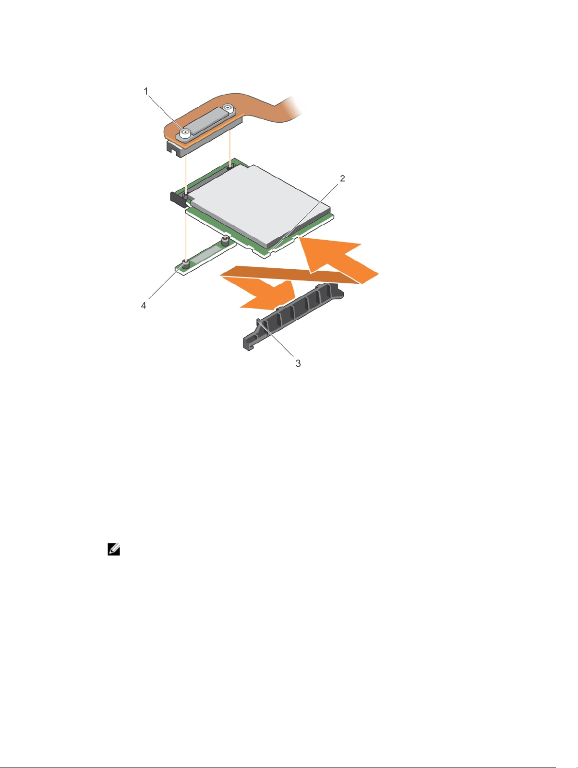
Figure 13. Removing and installing the PERC 9 mini blade controller
1. hard-drive/SSD backplane cable
connector
3. tabs on the PCIe extender/storage
controller card support bracket
2. slot on the PCIe extender/storage
controller card
4. standoff (2)
Replacing the tethered battery of a PERC 9 mini blade card
The tethered battery attached to the PERC 9 mini blade card can be replaced. This tethered battery
feature is applicable only to the PowerEdge FC630 and FC830 systems.
1. Turn off the system, including any attached peripherals, and disconnect the system from the
electrical outlet and peripherals.
NOTE: It is recommended that you always use a static mat and static strap while working on
components in the interior of the system.
2. Open the system.
3. Locate the battery carrier of the PERC card on the system board.
4. Push the tab on the battery carrier forward until the battery carrier disengages from the slot of the
chassis.
49
Page 50
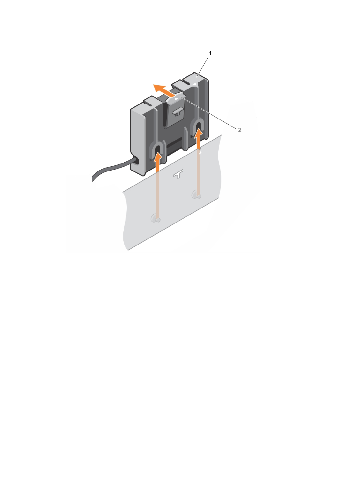
Figure 14. Removing the battery carrier
1. tab on the battery carrier 2. battery carrier of the tethered battery
5. Disconnect the battery cable connector from the connector on the mini blade and lift the battery
carrier away from the system.
6. Pull the battery out of the battery carrier.
50
Page 51
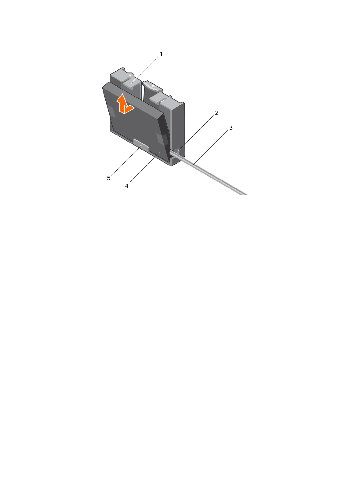
Figure 15. Removing the battery from the battery carrier
1. battery carrier 2. slot on the tethered battery carrier
3. tethered battery cable 4. battery
5. guide for the battery on the battery carrier
7. Align the lower end of the replacement battery into the battery carrier and push the battery towards
the carrier until it clicks into place.
51
Page 52
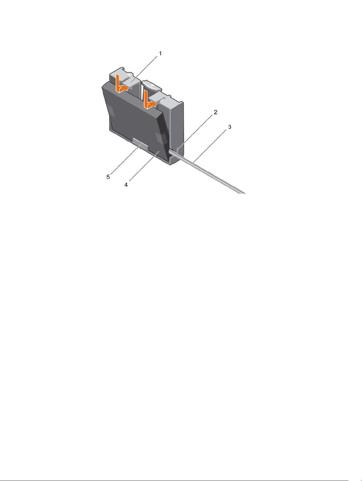
Figure 16. Installing the battery into the battery carrier
1. battery carrier 2. slot for the tethered battery carrier
3. tethered battery cable 4. battery
5. guide for the battery on the battery carrier
8. Align the battery carrier with the guide pin slots on the chassis and lower the battery carrier until the
guide pin slots on the battery carrier engage with the guide pins on the chassis
52
Page 53
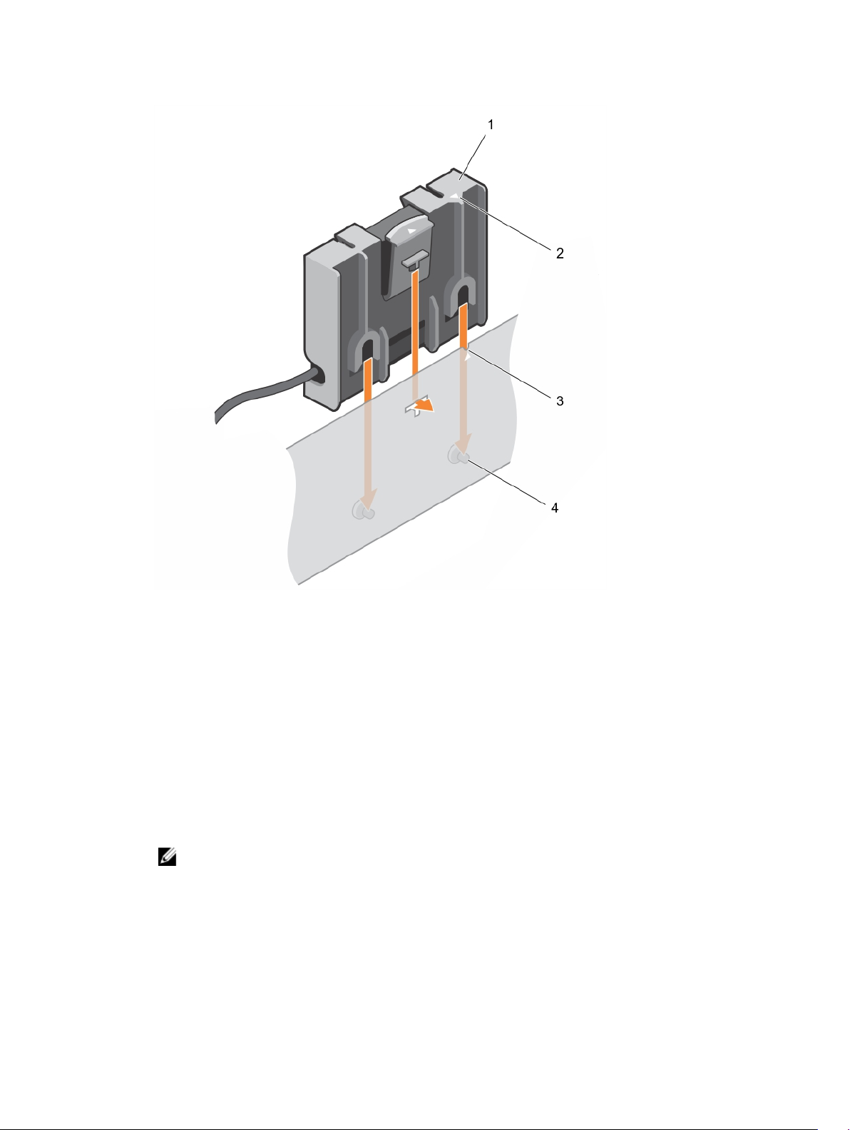
Figure 17. Replacing the battery carrier
1. battery carrier 2. tab on the battery carrier
3. guide slot on the chassis 4. guide pins on the chassis
9. Connect the battery cable to PERC 9 mini blade controller.
10. Close the system.
11. Reconnect the system to its electrical outlet and turn on the system, including any attached
peripherals.
Installing the PERC 9 mini blade controller
1. Turn off the system, including any attached peripherals, and disconnect the system from the
electrical outlet.
NOTE: It is recommended that you always use a static mat and static strap while working on
components in the interior of the system.
2. Open the system.
3. Remove the NDC riser.
4. Lift the clamp attached to the power supply bay and locate the PERC 9 card connector on the
system board.
53
Page 54
CAUTION: To prevent damage to the card, you must hold the card by its edges only.
5. Align the following:
a. screw holes on the PERC 9 mini blade controller with the standoffs on the system board
connector.
b. slots on the PERC 9 mini blade controller edge with the tabs on the support bracket.
6. Lower the PERC 9 mini blade controller onto the connector on the system board.
7. Tighten the two retention screws on the hard-drive/SSD backplane cable connector to secure the
card on to the system board.
8. Install the tethered battery cable, if applicable.
9. Close the clamp.
10. Install the NDC riser.
11. Close the system.
12. Reconnect the system to its electrical outlet and turn the system on, including any attached
peripherals.
Removing the PERC FD33xD Card
CAUTION: Many repairs may only be done by a certified service technician. You should only
perform troubleshooting and simple repairs as authorized in your product documentation, or as
directed by the online or telephone service and support team. Damage due to servicing that is
not authorized by Dell is not covered by your warranty. Read and follow the safety instructions
that came with the product.
NOTE: PERC FD33xS and FD33xD cards are supported only on PowerEdge FD332 system. The
procedure for removing a PERC FD33xS card is identical to removing a PERC FD33xD card.
1. Turn off the system, including any attached peripherals, and disconnect the system from the
electrical outlet and peripherals.
NOTE: It is recommended that you always use a static mat and static strap while working on
components in the interior of the system.
2. Open the system.
3. Locate the PERC card.
4. Loosen the screws securing the cable to the PERC card.
5. Lift the cable away from the PERC card by holding the cable touch point.
6. Holding the touch point, allow the cable to slowly retract into the cable coil.
7. Remove the screws securing the PERC card to the PERC card holder.
8. Holding it by the touch points, lift the PERC card from the connector on the midplane interface
module.
54
Page 55
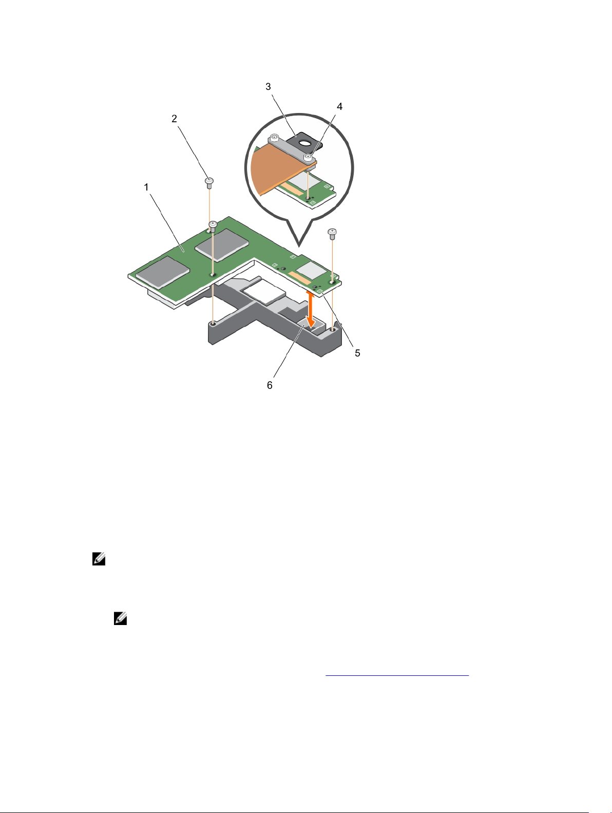
Figure 18. Removing and installing the PERC FD33xD card
1. PERC FD33xD card 2. screw (3)
3. touch point on the cable 4. cable screw (2)
5. touch point on the PERC card (4) 6. connector on midplane interface
9. Close the system.
10. Reconnect the system to its electrical outlet and turn on the system, including any attached
peripherals.
module
Replacing the battery of a PERC FD33xD card
NOTE: The procedure for replacing the battery of a PERC FD33xS card is identical to replacing the
battery of a PERC FD33xD card.
1. Turn off the system, including any attached peripherals, and disconnect the system from the
electrical outlet and peripherals.
NOTE: It is recommended that you always use a static mat and static strap while working on
components in the interior of the system.
2. Open the system.
3. Locate the PERC card.
4. Remove the PERC card. For more information, see Removing the PERC FD33xD Card.
5. Disconnect the battery cables from the PERC card.
55
Page 56
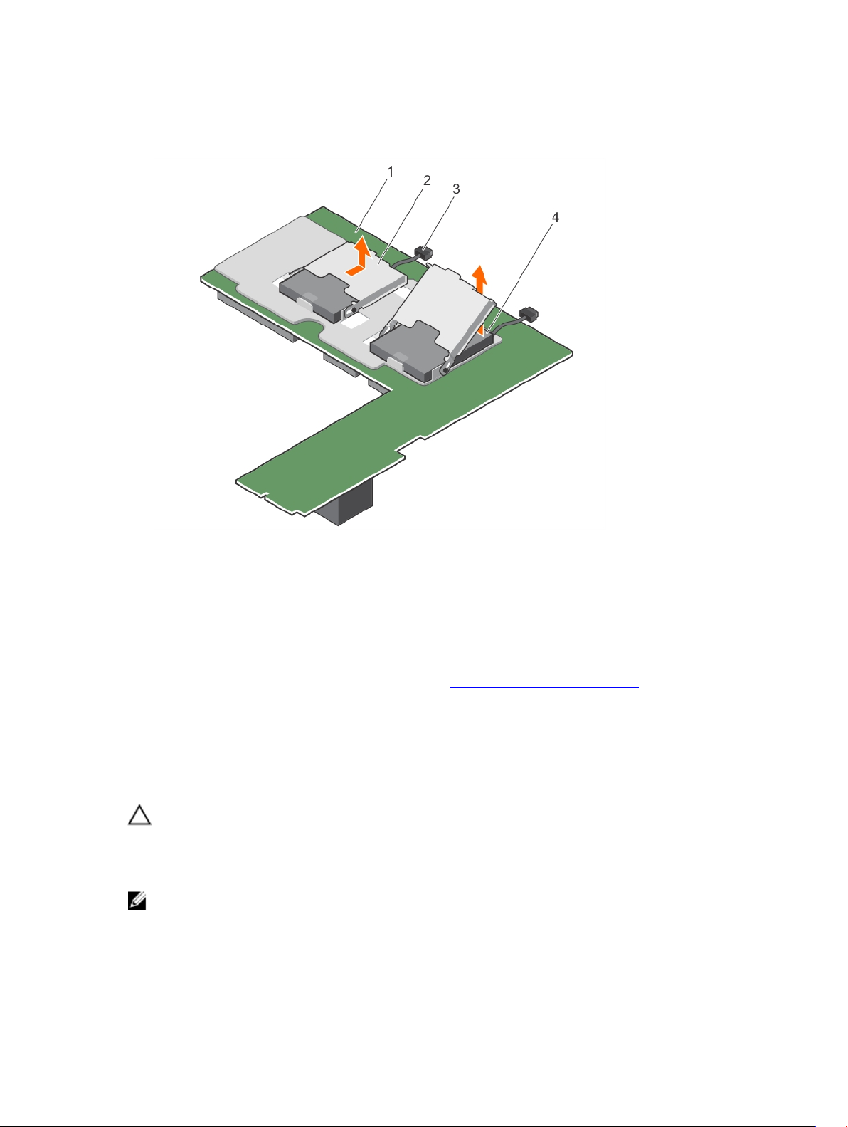
6. Slide the battery carrier in the direction of the arrow printed on the battery carrier, and then flip the
battery carrier open.
7. Remove the battery from the PERC card.
Figure 19. Removing the battery
1. PECR FD33xD card 2. battery carrier
3. battery cable 4. battery
8. Install the replacement battery on the controller.
9. Push the battery carrier toward the battery and slide the battery carrier till it clicks into place.
10. Connect the battery cables to the PERC card.
11. Replace the PERC card. For more information, see Installing the PERC FD33xD card.
12. Close the system.
13. Reconnect the system to its electrical outlet and turn on the system, including any attached
peripherals.
Installing the PERC FD33xD card
CAUTION: Many repairs may only be done by a certified service technician. You should only
perform troubleshooting and simple repairs as authorized in your product documentation, or as
directed by the online or telephone service and support team. Damage due to servicing that is
not authorized by Dell is not covered by your warranty. Read and follow the safety instructions
that came with the product.
NOTE: PERC FD33xS and FD33xD cards are supported only on PowerEdge FD332 system. The
procedure for installing a PERC FD33xS card is identical to installing a PERC FD33xD card.
1. Turn off the system, including any attached peripherals, and disconnect the system from the
electrical outlet.
56
Page 57

NOTE: It is recommended that you always use a static mat and static strap while working on
components in the interior of the system.
2. Open the system.
3. Align the PERC card with the connector on the midplane interface module.
4. Lower the PERC card until it is firmly seated on the connector on the midplane interface module.
5. Install the screws to secure the PERC card to the PERC card holder on the midplane interface
module.
6. Holding the cable touch point, align the cable guide pins with the holes on the PERC card.
7. Tighten the screws to secure the cable to the PERC card.
8. Close the system.
9. Reconnect the system to its electrical outlet and turn on the system, including any attached
peripherals.
57
Page 58

5
Driver installation
The Dell PowerEdge RAID Controller (PERC) 9 series of cards require software drivers to operate with the
supported operating systems.
This chapter contains the procedures for installing the drivers for the PERC 9 cards.
NOTE: The drivers for PERC 9 for VMware ESXi is packaged within the VMware ESXi ISO image
downloaded from Dell. For more information, see the VMware documentation at dell.com/
virtualizationsolutions. It is not recommended to have drivers from controllers prior to PERC 9 on
the same system.
The two methods for installing a driver discussed in this chapter are:
• Installing a driver during operating system installation: Use this method if you are performing a new
installation of the operating system and want to include the drivers.
• Updating existing drivers: Use this method if the operating system and the PERC 9 family of
controllers are already installed and you want to update to the latest drivers.
NOTE: It is recommended that you update existing operating system drivers after installation. Native
driver support is available for Windows 2012 R2.
Creating the device driver media
Use one of the following two methods to create the device driver media:
• Downloading Drivers From The Dell Systems Service And Diagnostic Tools Media
• Downloading Drivers From The Dell Support Website
Downloading drivers from the Dell support website
To download drivers from the Dell Support website:
1. Go to dell.com/support.
2. Enter the service tag of your system in the Choose by Service Tag to get started field or select
Choose from a list of all Dell products.
3. Select the System Type, Operating System, and Category from the drop-down list.
The drivers that are applicable to your selection are displayed.
4. Download the drivers that you require to a USB drive, CD, or DVD.
5. During the operating system installation, use the media that you created with the Load Driver option
to load mass storage drivers. For more information on reinstalling the operating system, see the
relevant section for your operating system below.
58
Page 59

Downloading drivers from the Dell systems service and diagnostic tools media
To download drivers from the Dell Systems Service and Diagnostic Tools media:
1. Insert the Dell Systems Service and Diagnostics Tools media in your system.
The Welcome to Dell Service and Diagnostic Utilities screen is displayed.
2. Select your system model and operating system.
3. Click Continue.
4. From the list of drivers displayed, select the driver you require.
5. Select the self-extracting zip file and click Run.
6. Copy the driver to a CD, DVD, or USB drive.
7. Repeat this procedure for all the drivers you require.
Windows driver installation
Before you install the Windows driver for PERC 9, you must first create a device driver media.
• Read the Microsoft Getting Started document that shipped with your operating system.
• Ensure that your system has the latest BIOS, firmware, and driver updates. If required, download the
latest BIOS, firmware, and driver updates from dell.com/support.
• Create a device driver media using one of the methods listed below:
– USB drive
– CD
– DVD
Installing the driver during a Windows Server 2008 R2 and newer installation
To install the driver:
1. Boot the system using the Windows Server 2008 R2, or newer media.
2. Follow the on-screen instructions until you reach Where do you want to install Windows Server
2008 R2 or newer window and then select Load driver.
3. The system prompts you to insert the media. Insert the installation media and browse to the
appropriate location.
4. Select a PERC 9 series card from the list.
5. Click Next and continue installation.
Installing the driver after Windows Server 2008 R2 and newer installation
Perform the following steps to configure the driver for the RAID controller on a system that already has
Windows installed:
1. Turn off the system.
2. Install the new RAID controller in the system.
For detailed instructions on installing the RAID controller in the system, see Deploying the PERC card.
3. Turn on the system.
The Found New Hardware Wizard screen displays the detected hardware device.
59
Page 60
4. Click Next.
5. On the Locate device driver screen, select Search for a suitable driver for my device and click Next.
6. Browse and select the drivers from the Locate Driver Files screen.
7. Click Next.
The wizard detects and installs the appropriate device drivers for the new RAID controller.
8. Click Finish to complete the installation.
9. Reboot the system when prompted.
Updating PERC 9 driver for existing Windows Server 2008 R2 and newer
NOTE: Close all applications on your system before you update the driver.
1. Insert the media (CD, DVD, or USB drive) containing the driver.
2. Select Start → Settings → Control Panel → System.
The System Properties screen is displayed.
NOTE: The path to System might vary depending on the operating system family.
3. Click on the Hardware tab.
4. Click Device Manager.
The Device Manager screen is displayed.
NOTE: The path to Device Manager might vary depending on the operating system family.
5. Expand SCSI and RAID Controllers by double-clicking the entry or by clicking on the plus symbol
next to SCSI and RAID Controller.
NOTE: In Windows Server 2008, Windows Server 2008 R2, and Windows Server 2012, the PERC
9 series of cards are listed under Storage Controllers.
6. Double-click the RAID controller for which you want to update the driver.
7. Click the Driver tab and click Update Driver.
The screen to update the device driver wizard is displayed.
8. Select Install from a list or specific location.
9. Click Next.
10. Follow the steps in the wizard and browse to the location of the driver files.
11. Select the INF file from the driver media (CD, DVD, or other media).
12. Click Next and continue the installation steps in the wizard.
13. Click Finish to exit the wizard and reboot the system for the changes to take place.
NOTE: Dell provides the Dell Update Package (DUP) to update drivers on systems running
Windows Server 2008 R2 and newer operating system. DUP is an executable application that
updates drivers for specific devices. DUP supports command line interface and silent execution.
For more information, see dell.com/support.
Linux driver installation
NOTE: PERC 9 series of drivers support PERC 5, PERC 6, PERC 7, and PERC 8 family controllers and
do not require separate driver installations.
60
Page 61
NOTE: The driver update disk (DUD) images are created only for those operating system releases in
which the native (in-box) driver is insufficient for installation. In the event that an operating system is
being installed with a corresponding DUD image, follow the instructions below.
Installing or updating the RPM driver package with KMOD support
NOTE: This procedure is applicable for Red Hat Enterprise Linux 6.5 SP2.
Perform the following steps to install the RPM package with KMOD support:
1. Uncompress the gzipped tarball driver release package.
2. Install the driver package using the command: rpm –ihv kmodmegaraid_ sas-<version>.rpm.
NOTE: Use rpm -Uvh <package name> when upgrading an existing package.
3. If the previous device driver is in use, you must reboot the system for the updated driver to take
effect.
4. Verify that the driver is loaded with the following system commands: modinfo megaraid_sas.
Installing or updating the RPM driver package with KMP support
NOTE: This procedure is applicable for SUSE Enterprise Linux 11 SP2.
Perform the following steps to install the RPM package with KMP support:
1. Uncompress the gzipped tarball driver release package.
2. Install the driver package using the command: rpm –ihv kmpmegaraid_ sas- <version>.rpm.
NOTE: Use rpm -Uvh <package name> when updating an existing package.
3. If the previous device driver is in use, you must reboot the system for the updated driver to take
effect.
4. Verify that the driver is loaded with the following system commands: modinfo megaraid_sas.
61
Page 62
6
BIOS Configuration Utility
The BIOS Configuration Utility, (<Ctrl> <R>), is a storage management application embedded on the
PERC 9 cards that configure and maintain RAID disk groups and virtual disks. <Ctrl> <R> is independent of
the operating system.
NOTE: Use the BIOS Configuration Utility (<Ctrl> <R>) for initial setup and disaster recovery. You
can use advanced features through Dell OpenManage storage management application and Dell
SAS RAID storage manager.
The following sections provide information about using the BIOS Configuration Utility (<Ctrl> <R>). For
more information, see the online help option by pressing <F1> in the BIOS Configuration Utility (<Ctrl>
<R>).
NOTE: The PERC 9 card configuration utility refreshes the screen every 15 seconds to show
changes to the information. You can also press <F5> to refresh the screen.
Entering the BIOS Configuration Utility
Perform the following steps to enter the BIOS Configuration Utility (<Ctrl> <R>) when you boot the
system:
1. Turn on the system.
A BIOS screen displays information about the controller and configuration.
2. During startup, press <Ctrl> <R> when prompted by the BIOS screen.
3. Use the arrow keys to select the RAID controller you want to configure, and press <Enter> to access
the management menus for the controller.
If there is only one controller, the Virtual Disk Management screen for that controller is displayed. If
there is more than one controller, the main menu screen is displayed. The screen lists the RAID
controllers.
NOTE: You can access multiple controllers through the BIOS Configuration Utility (<Ctrl> <R>)
by pressing <F12>.
Exiting the Configuration Utility
To exit the BIOS Configuration Utility (<Ctrl> <R>)
1. Press <Esc> on any menu screen.
If there is only one controller, then a dialog box is displayed to confirm your choice.
2. Select OK to exit and press <Enter>.
If multiple controllers are present, then the <Esc> key brings you to the Controller Selection screen.
62
Page 63

3. Press <Esc> again to reach the exit screen.
A dialog box is displayed to confirm your choice.
4. Select OK to exit and press <Enter>.
Menu navigation controls
The following table displays the menu keys you can use to move between the different screens in the
BIOS Configuration Utility (<Ctrl> <R>).
Table 3. Menu navigation keys
Notation Meaning and Use Example
rightarrow
key
leftarrow
key
uparrow
key
downarrow
key
<Enter> After you highlight a menu item, press
<Esc> After you expand a pop-up window, press
Use the right-arrow key to open a submenu,
move from a menu heading to the first
submenu, or move to the first item in that
submenu. If you press the right-arrow key at
a menu heading, the submenu expands. Press
it again to go to the first item in the submenu.
The right-arrow key is also used to close a
menu list in a popup window. Word wrap is
supported.
Use the left-arrow key to close a submenu,
move from a menu item to the menu heading
for that item, or move from a submenu to a
higher level menu. If you press the left-arrow
key at a menu heading, the submenu
collapses. Press it again to go to the higherlevel menu. Word wrap is supported.
Use the up-arrow key to move to the upper
menu items within a menu or to a higher level
menu. You can also use the up-arrow key to
close a menu list in a popup window, such as
the stripe element size menu. Word wrap is
supported.
Use the down-arrow key to move to the
lower menu items within a menu or to a
lower level menu. You can also use the
down-arrow key to open a menu list in a
popup window, such as the stripe element
size menu, and select a setting. Word wrap is
supported.
<Enter> to select that item. An options menu
for the menu item opens. It applies to only
certain menu items, such as Virtual Disk #. In
a list of options for that item, such as the
write policy for a virtual disk, highlight a
setting, such as
<Enter> to select it.
<Esc> to close the window. You can continue
Write-Through, and press
Start → Programs
Controller 0 ← Disk Group 1
Virtual Disk 1
↑
Virtual Disk 4
Virtual Disk 1
↓
Virtual Disk 4
Select Add New VD and press <Enter> to
create a new virtual disk.
Press <Esc> to return to the VD Mgmt
screen.
63
Page 64

Notation Meaning and Use Example
to press <Esc> to exit the BIOS Configuration
Utility (<Ctrl> <R>).
<Tab> Press <Tab> to move the cursor to the next
control on a dialog box or page.
<Shift>
<Tab>
<Ctrl>
<N>
<Ctrl>
<P>
<F1> Press <F1> to accessHelp information. The
<F2> Press <F2> to access the context menu,
<F5> Press <F5> to refresh the information on the
<F11> Switch between two controllers. <F11>
<F12> Press <F12> to display a list of controllers. <F12>
Spacebar Press the <spacebar> to select an item. Press the <spacebar> to select or deselect a
Press <Shift> <Tab> to move the cursor to the
previous control on a dialog or page.
Press <Ctrl> <N> to move to the next menu
screen among the main menu screens: VD
Mgmt, PD Mgmt, Ctrl Mgmt, and Foreign
View.
Press <Ctrl> <P> to move to the previous
menu screen among the main menu screens:
VD Mgmt, PD Mgmt, Ctrl Mgmt, and Foreign
View.
Help screens display a glossary of topics you
can use to access information about
navigation, RAID levels, and general topics.
which displays the list of options.
screen.
Press <Tab> to move the cursor to the next
parameter you want to change.
Press <Shift> <Tab> to move the cursor from
Sort By to the previously selected PD in
thePD Mgmt screen.
Press <Ctrl> <N> on the VD Mgmt screen to
move to the PD Mgmt screen.
Press <Ctrl> <P> on the PD Mgmt screen to
move to the VD Mgmt screen.
<F1>
<F2>
<F5>
controller setting in the Ctrl Mgmt View.
Setting up virtual disks
You can set up a disk group and create virtual disks using the procedures in this section. Each procedure
is explained individually in this section in detail.
To set up virtual disks:
1. Create virtual disks. See Creating virtual disks.
2. Select the virtual disk options.
3. Designate hot spares (optional).
For more information, see Managing dedicated hot spares.
4. Initialize the virtual disks.
NOTE: When you use one physical disk group to create multiple virtual disks, all the virtual disks
must be configured with the same RAID level.
When you define the virtual disks, you can set the following virtual disk parameters:
• RAID level
64
Page 65
• Stripe element size
• Read policy
• Write policy
• Type of initialization
• Hot spare configuration
NOTE: The default hard drive cache policy for a virtual disk with SAS hard drives is disabled
and virtual disk with SATA hard drives is enabled. The Virtual Disk parameter cannot be
changed in the BIOS Configuration Utility (<Ctrl> <R>). Use Dell OpenManage Storage
Management for the hard drive cache setting operation.
The following table shows the parameters that you can configure when defining virtual disks.
Table 4. Parameters — description
Parameter Description
RAID Level Specifies whether the virtual disk is RAID 0, 1, 5, 6, 10, 50, or 60. The number
of disks, disk capacity, requirements for fault tolerance, performance, and
capacity should be considered when selecting the RAID level.
Stripe Element Size Specifies the size of the segments written to each physical disk in a RAID 0, 1,
5, 6, 10, 50, and 60 virtual disk. You can set the stripe element size to 64 KB
128 KB, 256 KB, 512 KB, or 1 MB. The default and recommended stripe
element size is 64 KB.
A larger stripe element size provides better read performance if your system
mostly does sequential reads.
Write Policy Specifies the controller write policy. You can set the write policy to Write-
Back or Write-Through.
In Write-Back caching, the controller sends a data transfer completion signal
to the host when the controller cache has received all the data in a
transaction.
NOTE: If a Battery Backup Unit (BBU) is present, the default cache setting
is Write-Back. If no BBU is present, the default cache policy default
setting is Write-Through.
NOTE: If Write-Back is enabled and the system is turned off and then on,
the controller may pause as the system flushes cache memory.
Controllers have a battery backup default to Write-Back caching.
In Write-Through caching, the controller sends a data transfer
completion signal to the host when the disk subsystem has received all
the data in a transaction.
Read Policy Read-Ahead enables the read-ahead feature for the virtual disk. You can set
the parameter to Read-Ahead, No-Read-Ahead, or Adaptive-Read-Ahead.
The default is Adaptive-Read-Ahead.
Read-Ahead specifies that the controller uses Read-Ahead for the current
virtual disk. Read-Ahead capability allows the controller to read sequentially
ahead of requested data and store the additional data in the cache memory,
anticipating that the data is required soon.
65
Page 66

Parameter Description
No-Read-Ahead specifies that the controller does not use read ahead for the
current virtual disk.
BIOS Configuration Utility menu options
The first menu that is displayed when you access the BIOS Configuration Utility <Ctrl> <R> is the main
menu screen. It lists the controller, controller number, and other information, such as the slot number.
On the screen, you can use the arrow keys to select the RAID controller you want to configure. Press
<Enter> to access the controller
This section describes the options for the BIOS Configuration Utility (<Ctrl> <R>) for each of the major
menus:
• Virtual Disk Management (VD Mgmt) menu
• Physical Disk Management (PD Mgmt) menu
• Controller Management (Ctrl Mgmt) menu
• Foreign Configuration View (Foreign View) menu
Most menus consist of two panels:
• A left panel with the menu options
• A right panel with details of the items selected in the left panel
The following sections describe the menu and submenu options for each of the major menus:
Virtual disk management
The Virtual Disk Management screen, VD Mgmt is the first screen that is displayed when you access a
RAID controller from the main menu screen on the BIOS Configuration Utility (<Ctrl> <R>). The left
panel displays the menus for the virtual disk management as given below:
Controller—Consists of the sub-menu item Disk Group which again has the following sub-menu items:
• Virtual Disks
• Physical Disks
• Total Free Capacity (virtual disk size and free space you can use to create a virtual disk)
• Hot Spares (global and dedicated)
The right panel displays detailed information for the selected controllers, disk groups, virtual disks,
physical disks, total free capacity, and hot spares, as shown in the following table:
Table 5. Information on the virtual disk management screen
Menu Item Selected in Left Panel Information Displayed in Right Panel
Controller Controller Properties:
• Number of disk groups (DG)
• Number of virtual disks (VD)
66
Page 67

Menu Item Selected in Left Panel Information Displayed in Right Panel
• Number of physical disks (PD)
Disk Group # Disk Group # Properties:
• Number of virtual disks (VD)
• Number of physical disks (PD)
• Space available on the physical disks
• Number of free segments
• Number of dedicated hot spares
• Security property of the Disk Group
Virtual Disks Disk Group # Properties:
• Number of virtual disks (VD)
• Number of physical disks (PD)
• Space available in the virtual disk
• Number of free segments
• Number of dedicated hot spares
Virtual Disk # Virtual Disk # Properties:
• RAID level (0, 1, 5, 6, 10, 50, or 60)
• RAID status of the virtual disk (Failed, Degraded, Partially
Degraded, or Optimal)
• Operation currently in progress
Disk Group # Properties:
• Number of virtual disks (VD)
• Number of physical disks (PD)
• Space available on the physical disks
• Number of free segments
• Number of dedicated hot spares
Physical Disks Disk Group # Properties:
• Number of virtual disks (VD)
• Number of physical disks (PD)
• Space available on the physical disks
• Number of free segments
• Number of dedicated hot spares
Physical Disk # Physical Disk Properties:
• Vendor name
• Physical disk state
• Enclosure Position
• Slot Position
Disk Group # Properties:
• Number of virtual disks (VD)
• Number of physical disks (PD)
67
Page 68

Menu Item Selected in Left Panel Information Displayed in Right Panel
• Space available on the physical disks
• Number of free segments
• Number of dedicated hot spares
Total Free Capacity Disk Group # Properties:
• Number of virtual disks (VD)
• Number of physical disks (PD)
• Space available on the physical disks
• Number of free segments
• Number of dedicated hot spares
Hot Spares Physical Disk Properties:
• Vendor name
• Physical disk state
• Enclosure Position
• Slot Position
Disk Group # Properties:
• Number of virtual disks (VD)
• Number of physical disks (PD)
• Space available on the physical disks
• Number of free segments
• Number of dedicated hot spares
Virtual disk actions
The following table describes the actions you can perform on virtual disks. For detailed information on
each action below, see Virtual Disk Management.
Table 6. Virtual disk actions
Action Description
Create a new virtual
disk
Manage dedicated
hot spares
Initialize a virtual disk Initializes the selected virtual disk. You must initialize every virtual disk that is
Check data
consistency on a
virtual disk
Display or update
virtual disk
parameters
Creates a new virtual disk from one or more physical disks. You can configure
hot spares when you create a virtual disk.
Creates or deletes a hot spare, which is dedicated to a single redundant virtual
disk.
configured. You can perform a fast initialization or a full initialization.
Verifies the correctness of the redundancy data in the selected virtual disk. The
option is available only if RAID level 1, 5, 6, 10, 50, or 60 is used. The PERC 9
series of cards automatically correct any differences found in the data.
Displays the properties of the selected virtual disk. You can modify the cache
write policy and read policy from the menu.
68
Page 69

Action Description
Manage preserved
cache
Delete a virtual disk Deletes the virtual disk and frees up disk space to create another virtual disk.
Delete a disk group Deletes a disk group, which is a collection of disks from one or more disk
Preserves the dirty cache from a virtual disk if it goes offline or is deleted. The
dirty cache is preserved until you import the virtual disk or discard the cache.
subsystems controlled by the management software.
Physical disk management (PD Mgmt)
The Physical Disk Management screen (PD Mgmt) displays physical disk information and action menus.
The screen displays physical disk IDs, vendor names, disk size, type, state, and disk group (DG). You can
sort the list of physical disks based on the headings. You can perform several actions on the physical
disks, including the following:
• Rebuilding physical disks
• Performing the Replace Member operation
• Setting the LED to blink
• Making a disk online or offline (unaffiliated with a disk group)
• Creating global hot spares
• Removing dedicated hot spares or global hot spares
The PD Mgmt screen also displays several physical disk properties as shown in the following table.
Table 7. Information on the Physical Disk Management Screen
Information Displayed in Left Panel Supported Information Displayed in Right Panel
Physical Disk:
• Disk ID
• Protocol type
• Capacity (GB)
• Physical Disk State
• Disk Group
• Vendor
• Security Property of Physical Disk
• Encryption Capable
• Product ID
• Firmware Revision
• Disk Write Cache
• S.M.A.R.T state
• Physical Disk operation
• Max Device Link Rate
• Negotiated Link Rate
• Dell Certified Disk (512 or 4k)
Physical disk actions
The following table describes the actions you can perform on physical disks. For procedures that can be
used to perform the actions, see Physical Disk Management (PD Mgmt).
69
Page 70

Table 8. Physical disk actions
Action Description
Rebuild Regenerates all data to a replacement disk in a redundant virtual disk (RAID level
1, 5, 6, 10, 50, or 60) after a disk failure. A disk rebuild normally occurs without
interrupting normal operations on the affected virtual disk.
Replace Member Replaces the disk in the virtual disk with another disk that can be selected.
LED Blinking Indicates when physical disks are being used to create a virtual disk. You can
choose to start or stop the LED blinking.
Force Online Changes the state of the selected physical disk to online.
Force Offline Changes the state of the selected physical disk so that it is no longer part of a
virtual disk.
Make Global HS
Remove HS Removes a dedicated hot spare from its disk group or a global hot spare from
Designates the selected physical disk as a global hot spare. A global hot spare is
part of a pool for all virtual disks controlled by the controller.
the global pool of hot spares.
Rebuild
Select Rebuild to rebuild one or more failed physical disks. For information on performing a physical disk
rebuild, see Performing A Manual Rebuild Of An Individual Physical Disk.
Several of the controller configuration settings and the virtual disk settings affect the actual rate of
rebuild. The factors include the rebuild rate setting, virtual disk stripe size, virtual disk read policy, virtual
disk write policy, and the amount of workload placed on the storage subsystem. For information on
getting the best rebuild performance from your RAID controller, see the documentation at dell.com/
storagecontrollermanuals.
The listed rates in the following table were taken during single disk failure with no I/O. Rates vary
depending on type, speed and number of hard drives present in array; as well as which controller model
and enclosure configuration are being used.
Table 9. Estimated rebuild rates
RAID Level Number of Hard Drives 7.2 K rpm 12 Gbps SAS Hard
Drive
RAID 1 2 320 GB/hour 500 GB/hour
RAID 5 6 310 GB/hour 480 GB/hour
RAID 10 6 320 GB/hour 500 GB/hour
RAID 5 24 160 GB/hour 240 GB/hour
RAID 10 24 380 GB/hour 500 GB/hour
15 K rpm 6 Gbps SAS
Hard Drive
Controller management (Ctrl Mgmt)
The Controller Management screen (Ctrl Mgmt) displays the product name, package, firmware version,
BIOS version, boot block version, controller ID, security capability, and security key presence. Use the
70
Page 71
screen to perform actions on the controller and BIOS. You can perform functions such as enable or
disable the controller BIOS, enable or disable the BIOS during bootup in the event of BIOS errors, and
enable or disable the option to Auto Import. In addition, you can select a virtual disk from which to boot,
and select default settings.
Controller management actions
The following table describes the actions you can perform on the Ctrl Mgmt screen.
Table 10. Controller management options
Option Description
Enable Controller BIOS
Enable BIOS Stop On Error Select the option to stop the system BIOS during
Select Bootable Device
Select the option to enable the controller BIOS. If
the boot device is on the RAID controller, the BIOS
must be enabled.
Disable the BIOS to use other boot devices.
In a multiple controller environment, you can
enable the BIOS on multiple controllers. However,
if you want to boot from a specific controller, then
enable the BIOS on that controller and disable it
on the other controllers. The system can then boot
from the BIOS-enabled controller.
bootup if there are BIOS errors. The option enables
you to enter the configuration utility to resolve the
problem.
WARNING: Do not enable the BIOS Stop On
Error option when the system is operating in
UEFI mode.
Select the option to specify a virtual disk as the
boot disk on the controller.
The option is displayed if you have built virtual
disks.
Enable Auto Import Attempts to import every online foreign
configuration during boot without having the need
to access the BIOS Configuration Utility (<Ctrl>
<R>).
Factory Default Select the option to restore the default settings for
the options in the Settings box.
Personality Mode Select this option to switch to the HBA mode. the
default mode is RAID-mode.
71
Page 72

Foreign configuration view
When a foreign configuration is present, you can select Foreign Configuration View to display the
configuration. The screen shows the foreign configuration as it would be if you import it. You can
preview the foreign configuration before you decide whether to import it or clear it.
In some cases, a foreign configuration cannot be imported. If a physical disk in a virtual disk is rebuilding,
the physical disk's state is set to Rebuild. Virtual disks that cannot be imported do not display the virtual
disk target id.
The section Importing or Clearing Foreign Configurations Using the Foreign Configuration View Screen
contains the procedures you can use to manage the foreign configurations.
NOTE: The BIOS Configuration Utility (<Ctrl> <R>) reports error codes for failed imports of foreign
configurations.
Virtual Disk Management
Creating virtual disks
NOTE: Combining SAS and SATA disk drives within a virtual disk is not supported. Also, combining
disk drives and SSDs within a virtual disk is not supported.
NOTE: To create secured virtual disks, see Security Key And RAID Management.
Perform the following steps to create a virtual disk:
1. During host system bootup, press <Ctrl><R> after the BIOS screen is displayed.
The Virtual Disk Management screen is displayed. If there is more than one controller, the main
menu screen is displayed. Select a controller, and press <Enter>. The Virtual Disk Management
screen is displayed for the selected controller.
2. Use the arrow keys to highlight the PERC 9 series of adapters, for example thePERC H730P Adapter
or Disk Group #.
3. Press <F2>.
A list of available actions is displayed.
4. Select Create New VD and press <Enter>.
The Create New VD screen is displayed. The cursor is on the RAID Level option. When adding a
virtual disk to a Disk Group, the Add VD in Disk Group screen is displayed. Skip to step 11 to change
the basic settings of the virtual disk.
5. Press <Enter> to display the possible RAID levels.
6. Press the down-arrow key to select a RAID level and press <Enter>.
7. When creating a spanned virtual disk (RAID 50 or 60), enter the number of physical disks per span in
the PD per Span field and press <Enter>.
8. Press <Tab> to move the cursor to the list of physical disks.
9. Use the arrow key to highlight a physical disk and press the spacebar, <Alt> , or <Enter> to select the
disk.
10. Select additional disks, if required.
11. Press <Tab> to move the cursor to the Basic Settings box.
12. Set the virtual disk size in the VD Size field.
72
Page 73
The virtual disk size is displayed in GB format.
13. Press <Tab> to access the VD Name field, and type a virtual disk name.
14. Press <Tab> to move the cursor to Advanced settings
15. Press the spacebar to make the settings active so that you can change them.
An X is displayed beside Advanced settings. The settings are the stripe size, read policy, write policy,
and disk cache policy. You can also choose advanced options such as forcing the cache policy to
Write-Back, initializing the virtual disk, and configuring a dedicated hot spare. The default parameters
are displayed. You can accept the defaults or change them. To change the virtual disk parameters,
see Virtual Disk Parameters and Descriptions in Setting up virtual disks.
Selecting virtual disk parameters
To select the virtual disk parameters:
1. On the VD Mgmt screen, press <Tab> to move the cursor to the parameters you want to change.
2. Press the down-arrow key to expand the parameters and scroll down the list of settings.
3. To change the stripe element size, press <Tab> to highlight Stripe Size.
4. Press <Enter> to display the list of stripe element sizes (64 KB, 128 KB, 256 KB, 512 KB, and 1 MB).
The default stripe size is 64 KB.
5. Press the down-arrow key to highlight the desired option and press <Enter>.
6. To change the read policy, press <Tab> to move the cursor to Read Policy.
7. Press <Enter> to display the options (No Read Ahead, Read Ahead, or Adaptive Read Ahead).
8. Press the down-arrow key to highlight the desired option and press <Enter>.
9. To change the write policy, press <Tab> to move the cursor to Write Policy.
10. Press <Enter> to display the options (Write-Through, Write Back).
11. Press the down-arrow key to highlight an option and press <Enter>.
12. Press <Tab> to move the cursor to Force WB with no battery and press <Enter>.
NOTE: If you chose Write-Through as the write policy, then the option Force WB with no
battery is not available.
CAUTION: Do not initialize virtual disks when attempting to recreate an existing
configuration.
13. Press <Tab> to move the cursor to Initialize and press <Enter>.
NOTE: Fast initialization is performed at this stage.
14. Press <Tab> to move the cursor to Configure Hot Spare and press <Enter>.
NOTE: The hot spare created at the stage is a dedicated hot spare.
15. If you have chosen to create hot spares in the earlier steps, a pop-up window is displayed where
disks with appropriate sizes are displayed. Press the <spacebar> to select the disk size.
16. After you select the disk size, click OK to finalize the selection or click Cancel to forfeit the selection.
17. Select OK to accept the settings and press <Enter> to exit the window or select Cancel and press
<Enter> to exit if you do not want to change any virtual disk parameters.
Initializing virtual disks
CAUTION: A full initialization permanently destroys any existing data on that virtual disk.
73
Page 74

Perform the following steps to initialize virtual disks:
1. On the VD Mgmt screen, select Virtual Disk # and press <F2> to display the menu of available
actions.
2. Select Initialization and press the right-arrow key to display the Initialization submenu options.
3. Select Start Init. to begin a regular initialization or select Fast Init. to begin a fast initialization.
A pop-up window is displayed indicating that the virtual disk has been initialized.
4. Repeat the procedures from step 1 to step 3 to configure another virtual disk.
NOTE: The current configured virtual disks display on the screen.
Checking data consistency
Select the Consistency Check (CC) option in the configuration utility to verify the redundancy data in
virtual disks that use RAID levels 1, 5, 6, 10, 50, and 60 (RAID 0 does not provide data redundancy).
If you attempt to run a Consistency Check on a virtual disk that has not been initialized, the following
error message is displayed:
The virtual disk has not been initialized. Running a consistency check may
result in inconsistent message in the log. Are you sure you want to continue?
• Select Yes to proceed with running a CC.
• Select No to terminate the operation.
Running a data consistency check
To perform a data consistency check:
1. Press <Ctrl> <N> to access the VD Mgmt menu screen.
2. Press the down-arrow key to highlight Virtual Disk #.
3. Press <F2> to display the menu of available actions.
4. Press the down-arrow key to select Consistency Check.
5. Press the right-arrow key to display the available actions (Start, Stop).
6. Select Start and press <Enter> to run a Consistency Check.
The Consistency Check runs and checks the redundancy data in the virtual disks.
Importing or clearing foreign configurations using the VD mgmt menu
When a foreign configuration exists, the BIOS screen displays the message Foreign
configuration(s) found on adapter
side of the Ctrl Mgmt screen.
You can use the VD Mgmt menu to import the existing configuration to the RAID controller or clear the
existing configuration. In addition, you can view the foreign configuration from the Foreign View tab
without importing the configuration.
NOTE: The controller does not allow import of configurations that results in more than 64 virtual
disks.
NOTE: To import a secured foreign configuration, see Security Key And RAID Management.
Perform the following steps to import or clear foreign configurations:
. In addition, a foreign configuration is displayed on the right
1. During bootup, press <Ctrl> <R> when prompted by the BIOS screen.
74
Page 75

The VD Mgmt screen is displayed by default.
2. On the VD Mgmt screen, highlight the Controller #.
3. Press <F2> to display the available actions.
4. Navigate to the Foreign Config option and press the right arrow key to display the available actions:
a. Import
b. Clear
NOTE: Ensure that your virtual disk has all the physical disks by verifying that there are no
physical disks marked as Missing in the foreign view page and that all the disks appear as
expected before importing them.
5. Select Import to import the foreign configuration or Clear to delete the foreign configuration and
then press <Enter>.
If you import the configuration, the VD Mgmt screen displays detailed configuration information. It
includes information about the disk groups, virtual disks, physical disks, space allocation, and hot
spares.
Importing or clearing foreign configurations using the foreign configuration view screen
NOTE: To import a secured foreign configuration, see Security Key And RAID Management.
If one or more physical disks are removed from a configuration, the configuration on those disks is
considered a foreign configuration by the RAID controller.
You can use the Foreign Config screen to view information about the foreign configuration, such as disk
groups, virtual disks, physical disks, space allocation, and hot spares. The foreign configuration data is
displayed in the same format as configurations on the VD Mgmt screen. You can use the VD Mgmt
screen to view the foreign configuration before importing. After you view the foreign configuration, you
can either clear or import to the RAID controller.
NOTE: Before you import the foreign configuration, review the configuration on the screen to
ensure that it is the end result that you require.
You can use the Foreign Config screen to manage foreign configurations in the following cases:
• All the physical disks in a configuration are removed and re-inserted.
• Some of the physical disks in a configuration are removed and re-inserted.
• All the physical disks in a virtual disk are removed, but at different times, and then re-inserted.
• The physical disks in a non-redundant virtual disk are removed.
The following constraints apply to the physical disks that are considered for import:
• The disk state of a physical disk can change from the time the foreign configuration is scanned to
when the actual import occurs. The foreign import occurs only on disks that are in the Unconfigured
Good state.
• Disks in the failed or offline state cannot be imported.
• The firmware does not allow you to import more than eight foreign configurations.
To manage foreign configurations:
1. If all or some of the physical disks in a configuration are removed and reinserted, the controller
considers the disks to have foreign configurations. Perform the following steps:
75
Page 76

a. Select Foreign Config to display the foreign configuration information on the Foreign Config
screen.
b. Press <F2> to display the options (Import, Clear).
NOTE: You must have all the disks in the system before you perform the import operation.
c. Select Import to import the foreign configuration to the controller or select Clear to delete the
foreign configuration(s) from the re-inserted disk(s).
In the Preview Configuration Data window, the status of a physical disk that needs to be rebuilt is
displayed as Rebuild.
NOTE: When you import a foreign configuration, the dedicated hot spares in the
configuration are imported as dedicated hot spares on two conditions — the associated
virtual disk is already present or the associated virtual disk is also imported along with the
configuration.
NOTE: Start a consistency check immediately after the rebuild is complete to ensure data
integrity for the virtual disks. For more information about checking data consistency, see
Checking Data Consistency .
2. If all the physical disks in a virtual disk are removed at different times and re-inserted, the controller
considers the disks to have foreign configurations. Perform the following steps:
a. Select Foreign Configuration View to display the complete virtual disk, across different foreign
configurations and allow foreign configurations to be imported.
b. Press <F2> to display the options Import and Clear.
NOTE: You must have all the drives in the system before you perform the import operation.
c. Select Import to merge the foreign configurations with the existing configuration on the
controller or Clear to delete the foreign configuration(s) from the re-inserted disk(s).
If you select Import, all drives that were removed before the virtual disk became offline are
imported, and then automatically rebuilt.
NOTE: Start a consistency check immediately after the rebuild is complete to ensure data
integrity for the virtual disks. For more information about checking data consistency, see
Checking Data Consistency .
3. If the physical disks in a non-redundant virtual disk are removed, the controller considers the disks to
have foreign configurations. Perform the following steps:
a. Select Foreign Configuration View to display the complete foreign configuration information.
b. Press <F2> to display the options Import and Clear.
c. Select Import to import the foreign configurations to the virtual disk or Clear to delete the
foreign configuration(s) from the re-inserted disk(s).
No rebuilds occur after the import operation because there is no redundant data to rebuild the
disks with.
Break mirror
A Break Mirror is performed only on RAID 1 arrays. It provides a way to 'split' the mirror and spin-down
one of the hard disks, which can then be imported into the configuration of a different PERC 9 series
controller. This can be a useful way to:
• Create a disk image that can be imported and booted on a different system.
• Assist in software or configuration testing, where half of the mirror can be removed to ensure
configuration consistency.
76
Page 77
NOTE: The Break Mirror operation is not available within the booted operating system
environment. It is only available in the BIOS Configuration Utility (<Ctrl> <R>) utility and the
UEFI RAID configuration utility.
Break mirror in BIOS configuration utility
The RAID 1 virtual disk that you wish to split must be in an optimal state, and it cannot be running any
other background tasks.
To use the Break Mirror feature from the BIOS Configuration Utility (<Ctrl> <R>), perform the following
steps:
1. During boot up, press <Ctrl> <R> when prompted by the BIOS screen. If there is more than one
controller in the system, choose the controller.
The VD Mgmt screen is displayed by default.
2. Highlight the appropriate Disk Group.
3. Press <F2> to display the available actions.
4. Choose Break Mirror and press <Enter>.
A dialog box is displayed describing the operation and asking if you are sure you want to perform the
operation.
5. Select Yes to continue.
The exported disk (exporting configuration) spins down and the hard drive status LED starts flashing
to identify which drive must be removed.
The remaining disk (exporting configuration) is in a degraded state until the missing member is
replaced or rebuilt.
If there are any Global or Dedicated Hot Spare assigned, which fulfills the rebuild requirements for
the degraded RAID 1 disk, a rebuild starts automatically. If there is no hot spare assigned, then an hot
spare that meets all the requirements for the virtual disk must be assigned before the rebuild starts.
NOTE: Importing a broken mirror is the same as importing a foreign configuration. See
Importing Or Clearing Foriegn Configurations Using VD Mgmt Menu. The imported virtual disk
is in a degraded state until the missing member is rebuilt.
Managing preserved cache
If a virtual disk goes offline or is deleted goes of missing physical disks, the controller preserves the dirty
cache from the virtual disk. The preserved dirty cache, known as pinned cache, is preserved until you
import the virtual disk or discard the cache.
NOTE: Certain operations, such as creating a new virtual disk, cannot be performed if preserved
cache exists. You have to enter the BIOS Configuration Utility (<Ctrl> <R>) to resolve the situation
before you boot to the operating system. Messages are displayed notifying you that you must enter
the BIOS Configuration Utility (<Ctrl> <R>) to discard the preserved cache or import the virtual
disks with the preserved cache.
CAUTION: If there are any foreign configurations, it is strongly advised that you import the
foreign configuration before you discard the preserved cache. Otherwise, you might lose data
that belongs with the foreign configuration.
To manage the preserved cache:
1. On the VD Mgmt screen, click on a controller icon.
2. Press <F2> to display the available actions.
3. Select Manage Preserved Cache.
77
Page 78
A message is displayed advising you to import the foreign configuration before you discard the
preserved cache to avoid losing data belonging to the foreign configuration. Confirm whether you
want to continue. The Manage Preserved Cache screen displays the affected virtual disks.
4. You can choose to discard the cache on the Manage Preserved Cache screen. If you press Cancel,
the process is cancelled and the Preserved Cache Retained dialog box is displayed.
If you choose to discard the cache, you are prompted to confirm your choice. If you choose to retain
the cache, a message is displayed to notify you that you cannot perform certain operations while the
cache exists. Click OK to continue.
Managing dedicated hot spares
A dedicated hot spare automatically replaces a failed physical disk only in the selected disk group which
the hot spare is part of.
A dedicated hot spare is used before a global hot spare is used. You can create dedicated hot spares or
delete them on the VD Mgmt screen.
Perform the following steps to create or delete dedicated hot spares:
1. On the VD Mgmt screen, select Disk Group # and press <F2>.
The available menu options are displayed.
2. Select Manage Ded. HS and press <Enter>.
A screen displays a list of the current dedicated hot spares with an X beside them and the physical
disks that are available to create dedicated hot spares.
NOTE: The utility allows only disks of the same disk technology and of equal or greater size to
be selected as dedicated hot spare.
3. Use the following instructions to create or delete a dedicated hot spare:
• Creating a dedicated hot spare
1. Press the down-arrow key to highlight an available physical disk.
2. Press the spacebar to select the disk.
3. Repeat step 1 to step 2 for each dedicated hot spare that you want to create.
NOTE: An X is displayed beside the selected physical disk(s).
• Deleting a dedicated hot spare
1. Use the down-arrow key to highlight a current hot spare.
2. Press the spacebar to de-select the disk.
3. Repeat step 1 and step 2 for each dedicated hot spare that you want to delete.
4. Press <Enter> to confirm the changes.
The VD Mgmt screen displays the updated list of hot spares.
NOTE: If a global hot spare or dedicated hot spare is removed, reinserted and imported, it
regains its status as a hot spare. A dedicated hot spare becomes a global hot spare when the
disk group it was assigned to protect is no longer present during import.
Deleting virtual disks
NOTE: You cannot delete a virtual disk during an initialization.
NOTE: Warning messages appear stating the effect of deleting a virtual disk. Click OK twice to
complete the virtual disk deletion.
78
Page 79

Perform the following steps in the BIOS Configuration Utility (<Ctrl> <R>) to delete the virtual disks:
1. Press <Ctrl> <N> to access the VD Mgmt screen.
2. Use the arrow keys to move the cursor to Virtual Disks.
3. Press <F2>.
The action menu is displayed.
4. Select Delete VD and press <Enter>.
5. If there are multiple virtual disks in a Disk Group, select Total Free Capacity for the Disk Group in the
VD Mgmt screen.
The total amount of free space available in the Disk Group is displayed.
Deleting disk groups
You can delete disk groups using the BIOS Configuration Utility (<Ctrl> <R>). When you delete a disk
group, the utility also removes the virtual disks in that disk group.
To delete disk groups, perform the following steps in the BIOS Configuration Utility (<Ctrl> <R>):
1. Press <Ctrl> <N> to access the VD Mgmt screen.
2. Use the arrow keys to move the cursor to Virtual Disks.
3. Press <F2>.
The action menu is displayed.
4. Select Delete Disk Group and press <Enter>.
The disk group is deleted.
NOTE: When you delete a disk group, the remaining disk groups with higher numbers are
automatically renumbered. For example, if you delete disk group #2, then disk group #3 is
automatically renumbered as disk group #2.
Clearing the configuration
To clear the configuration, perform the following steps in the BIOS Configuration Utility (<Ctrl> <R>):
1. Press <Ctrl> <N> to access the VD Mgmt screen.
2. Select the controller using the arrow keys
3. Press <F2>.
The action menu is displayed.
4. Select Clear Config.
A pop-up window is displayed prompting for confirmation to delete all virtual disks.
5. Select YES to delete the virtual disks or NO to retain the configurations.
Physical Disk Management
Setting LED blinking
The LED blinking option indicates when physical disks are being used to create a virtual disk. You can
choose to start or stop the LED blinking.
Following the below procedures to set LED Blinking:
1. Press <Ctrl> <N> to access the PD Mgmt screen.
79
Page 80
A list of physical disks is displayed. The status of the each disk is displayed under the heading State.
2. Press the down-arrow key to highlight a physical disk.
3. Press <F2> to display the menu of available actions.
4. Press the down-arrow key to highlight LED Blinking.
5. Press the right-arrow key to display the available actions, Start and Stop.
6. Select Start to begin LED blinking or Stop to end LED blinking.
Creating global hot spares
You can use a global hot spare to replace a failed physical disk in any redundant array as long as the
capacity of the global hot spare is equal to or larger than the coerced capacity of the failed physical disk.
Perform the following steps to create global hot spares:
1. Press the down-arrow key to highlight a physical disk to change to a global hot spare.
2. Press <F2> to display the menu of available actions.
3. Press the down-arrow key to highlight Make Global HS and press <Enter>.
The physical disk is changed to a global hot spare. The status of the physical disk as a global hot
spare is displayed under the heading State.
NOTE: To replace a failed physical disk global hot spares must use the same disk technology
and must be equal or greater in size.
NOTE: To change additional physical disks to global hot spares, follow step 1 to step 4.
Removing global or dedicated hot spares
You can remove one global or dedicated hot spare at a time on the PD Mgmt screen. Perform the
following steps to remove a global hot spare or dedicated hot spare:
1. Press <Ctrl> <N> to access the PD Mgmt screen.
A list of physical disks is displayed. The status of the each disk is displayed under the heading State.
2. Press the down-arrow key to highlight a physical disk that is a hot spare.
3. Press <F2> to display the menu of available actions.
4. Press the down-arrow key to select Remove Hot Spare from the list of actions and press <Enter>.
The physical disk is changed to the Ready state. The status of the physical disk is displayed under the
heading State.
NOTE: Try to use physical disks of the same capacity in a specific virtual disk. If you use physical
disks with different capacities in a virtual disk, all physical disks in the virtual disk are treated as if
they have the capacity of the smallest physical disk.
NOTE: To remove additional global or dedicated hot spares, follow step 1 to step 4.
Replacing an online physical disk
In addition to the automatic Replace Member operation, you can manually replace any physical disk that
is part of a virtual disk using the
Perform the following steps to replace a physical disk:
1. In the Virtual Disk Management window, select Virtual Disk # and press the down-arrow key until
Physical Disks is highlighted.
2. Press the right-arrow key to expand the list of physical disks that are members of the virtual disk.
Replace Member functionality.
80
Page 81
3. Press the down-arrow key and highlight the desired physical disk you want to replace. Press <F2> to
expand the list of allowed operations on the disk.
4. Select Replace.
5. Select Start.
6. Press the down-arrow to highlight a replacement disk and then press the spacebar to select the disk.
7. Select OK to start the replacement.
NOTE: The replacement disk must be a hot spare or an unconfigured disk without a foreign
configuration. It must have the same or greater capacity and should be of the same type as the
disk it is replacing.
Restrictions and limitations
The following restrictions and limitations apply to the Replace Member operation:
• The Replace Member functions are restricted to one per array for RAID 0, RAID 1, and RAID 5, and two
per array for RAID 6.
• The Replace Member function and rebuild cannot run simultaneously on a RAID 6 virtual disk. The
rebuild operation has a higher priority, and the Replace Member operation is aborted if a rebuild
begins.
• The Replace Member function and rebuild cannot run simultaneously on a RAID 6 virtual disk. The
rebuild operation has a higher priority, and the Replace Member operation is aborted if a rebuild
begins.
Stopping background initialization
Background initialization (BGI) is the automated operation in which parity is created and written. BGI does
not run on RAID 0 virtual disks. Under certain conditions, the BIOS Configuration Utility (<Ctrl> <R>)
displays a message if you want to stop a BGI in progress. An alert message is displayed if a BGI is in
progress and you start any of the following actions:
• A Full Initialization on the virtual disk
• A Fast Initialization on the virtual disk
• A Consistency Check on the virtual disk
The following alert message is displayed:
The virtual disk is undergoing a background initialization process. Would you
like to stop the operation and proceed with the <full initialization/quick
initialization/consistency check> instead?
Click Yes to stop the BGI and start the requested operation or No to allow the BGI to continue.
Performing a manual rebuild of an individual physical disk
CAUTION: If a physical disk is a member of a disk group that contains multiple virtual disks and
one of the virtual disks is deleted when a rebuild operation is in progress, the rebuild operation
stops. You can then resume the rebuild operation manually using a storage management
application. To avoid interruption, ensure that none of the virtual disks are deleted until the
rebuild is complete.
Follow the procedures below to rebuild one failed physical disk manually:
1. Press <Ctrl> <N> to access the PD Mgmt screen.
81
Page 82

A list of physical disks is displayed. The status of each disk is displayed under the heading State.
2. Press the down-arrow key to highlight a physical disk that is in failed state.
3. Press <F2> to display a menu of available actions.
The Rebuild option is highlighted at the top of the menu.
4. Press the right-arrow key to display the rebuild options and select Start.
5. After you start the rebuild, press <Esc> to display the previous menu.
NOTE: You can also use the VD Mgmt screen to perform a manual rebuild. Use the arrow key
to highlight a physical disk, and press <F2>. In the menu that is displayed, select the Rebuild
option.
Controller Management
Enabling boot support
NOTE: See your system documentation to ensure the proper boot order is selected in the system
BIOS.
In a multiple controller environment, you can enable BIOS on multiple controllers. However, if you want
to boot from a specific controller, enable the BIOS on that controller and disable it on the other
controllers. The system can then boot from the BIOS-enabled controller. Perform the following steps to
enable the controller BIOS:
1. Press <Ctrl> <N> to access Ctrl Mgmt menu screen.
2. Press <Tab> to move the cursor to Enable Controller BIOS in the Settings box.
3. Press the spacebar to select Enable Controller BIOS.
An X is displayed beside Enable Controller BIOS.
4. Press <Tab> to move the cursor to the Apply button, and then press <Enter> to apply the selection.
The controller BIOS is enabled.
To disable the controller BIOS, use the spacebar to de-select the Enable Controller BIOS control,
and then select Apply and press <Enter>.
Enabling boot support for a BIOS-enabled controller
1. Press <Ctrl> <N> to access the Ctrl Mgmt menu screen.
2. Press <Tab> to move the cursor to the Select Boot Device in the Settings box.
3. Press the down-arrow key to display a list of virtual disks.
4. Use the down-arrow key to highlight a virtual disk.
5. Press <Enter> to select the disk.
6. Press <Tab> to move the cursor to the Apply button, and then press <Enter> to apply the selection.
Boot support is enabled for the selected controller.
82
Page 83

Enabling BIOS stop on error
BIOS stop on error is used to stop the system from booting if there are BIOS errors. Perform the following
steps to Enable BIOS Stop on Error.
1. Press <Ctrl> <N> to access the Ctrl Mgmt menu screen.
2. Press <Tab> to move the cursor to Enable BIOS Stop on Error in the Settings box.
3. Press the spacebar to select Enable BIOS Stop on Error.
An X is displayed beside Enable BIOS Stop on Error.
4. Press <Tab> to move the cursor to the Apply button, and then press <Enter> to apply the selection.
The controller BIOS is enabled.
Disabling BIOS stop on error
To disable BIOS stop on error:
1. Use the spacebar to de-select Enable BIOS Stop On Error.
2. Select Apply and press <Enter>.
The BIOS Stop On Error is disabled.
Enabling auto import
If there is a native configuration present on the controller, the option Enable Auto Import automatically
imports every online foreign configuration during boot without having the need to access the BIOS
Configuration Utility (<Ctrl> <R>).
NOTE: The controller automatically imports every optimal and degraded foreign configuration
without enabling the feature if there is no native configuration on the controller.
To enable auto import:
1. Press <Ctrl> <N> to access the Ctrl Mgmt menu screen.
2. Press <Tab> to move the cursor to Enable Auto Import in the Settings box.
3. Press the spacebar to select Enable Auto Import.
An X is displayed beside Enable Auto Import.
4. Press <Tab> to move the cursor to the Apply button, and then press <Enter> to apply selection.
The auto import is enabled.
Disabling auto import
To disable auto import:
1. Use the spacebar to de-select Enable Auto Import.
2. Select Apply and press <Enter>.
The auto import is disabled.
83
Page 84

Restoring factory default settings
You can use the Ctrl Mgmt menu screen to restore the default settings for the options in the Settings
box. The settings are Enable Controller BIOS, Enable BIOS Stop on Error, and Enable Auto Import.
Perform the following steps to restore default settings:
1. Press <Ctrl> <N> to access the Ctrl Mgmt menu screen.
2. Press <Tab> to move the cursor to the Settings box.
3. Use the spacebar to de-select the settings for the options in the Settings box.
4. Press <Tab> to move the cursor to the Factory Default box, and press <Alt>, <Enter>, or the
spacebar.
A dialog box is displayed for you to confirm your choice.
5. Select Ok and press <Enter>.
The defaults are automatically selected for the controller settings and are displayed in Settings.
84
Page 85

7
UEFI/HII RAID configuration utility
The UEFI (Unified Extensible Firmware Interface) RAID configuration utility is a storage management
application integrated into the System BIOS <F2>. It is used to configure and manage RAID disk groups,
virtual disks, and physical disks. This utility is independent of the operating system.
NOTE: The following sections provide information about using the UEFI RAID configuration utility.
For more information, see the online help option in the UEFI RAID configuration utility.
NOTE: Use the UEFI RAID configuration utility for initial setup and disaster recovery. Certain
advanced features are also offered in the utility.
Entering the UEFI configuration utility
Perform the following steps to boot to the UEFI configuration utility:
1. Turn on the system.
2. While the system startup, press <F2> to enter System Setup.
Displays the list of menu in the System Setup Main Menu screen.
3. Click Device Settings.
Device Settings list all the RAID controllers in the system.
To access the management menu for the controller, use the arrow keys or the mouse.
NOTE: For more information in all the options, click Help that is available on the top right-hand
corner of the browser screen. Help information for individual option menus can also be viewed
by scrolling down on each option.
NOTE: Some of the options within the UEFI RAID configuration utility are not present if the
controller does not support the corresponding feature. Options may also be grayed out if the
feature is supported in existing configuration.
Exiting the UEFI configuration utility
To exit the UEFI configuration utility, perform the following steps:
1. Click Finish at the bottom-right corner on the System Setup Main Menu screen.
Displays a warning message to confirm your choice.
2. Click Yes to exit the configuration utility.
Navigating to Dell PERC 9 configuration utility
1. Enter the UEFI configuration Utility. See Entering the UEFI configuration utility.
85
Page 86

The Device Settings screen displays a list of NIC ports and the Dell PERC 9 configuration utility.
2. To enter PERC 9 configuration utility, click Dell PERC 9 Configuration Utility.
Displays the list of Configuration Options:
• Controller Management — allows you to configure, manage, and view the controller properties.
• Virtual Disk Management — allows you to configure, manage, and view the virtual disk properties
• Physical Disk Management — allows you to configure, manage, view and perform varied
operations on the physical disk properties.
Configuration management
Creating virtual disks
1. Enter the Dell PERC 9 Configuration Utility. See Navigating to PERC 9 Configuration Utility.
2. Click Configuration Management → Create Virtual Disks.
3. Select the RAID level by selection the radio button next to the available RAID configurations.
4. If you want to create a secured virtual disk, select Secure Virtual Disk.
NOTE: The Secure Virtual Disk option is enabled and selected by default, only if the security
key has been configured. Only SED physical disks are listed.
5. If you want to protect the virtual disk data, select Use Data Protection.
NOTE: The Use Data Protection option is enabled only if the storage controller supports
protection of data. Virtual disks can be created with a mix of physical disks that are both
capable of data protection or not.
6. Select one of the following physical disk capacities:
• Unconfigured Capacity: Creates a virtual disk on unconfigured physical disks.
• Free Capacity: Utilizes unused physical disk capacity that is already part of a virtual disk.
7. To select the physical disks from which the virtual disks are being created, click Select Physical Disks.
This option is displayed if you select Unconfigured Capacity as your physical disk capacity.
8. To select the disk groups from which the virtual disks are being created, click Select Disk Group. This
option is displayed if you select
9. Specify the name for the virtual disk in the Virtual Disk Name field.
10. Specify the size of the virtual disk in the Virtual Disk Size field.
11. Select the unit for the virtual disk size.
12. Specify the read policy for the virtual disk. The options for read policy are:
• No Read Ahead
• Read Ahead
13. Specify the write policy for the virtual disk. The options for read policy are:
• Write Back
• Write Through
• Force Write Back
14. Select the cache setting of the virtual disk. You can either enable or disable the cache setting for the
virtual disk.
15. Select the virtual disk initialization method. The options are:
• No: The virtual disk is not initialized.
• Fast: The first 8 MB of the virtual disk is initialized.
Free Capacity as your physical disk capacity.
86
Page 87

• Full: The entire virtual disk is initialized.
16. Click Create Virtual Disk and the virtual disks are created with the specified parameters.
Creating profile based virtual disks
1. Enter the Dell PERC 9 Configuration Utility. See Navigating to PERC 9 Configuration Utility.
2. Click Configuration Management → Create Profile Based Virtual Disks.
3. Select the RAID type. The following are the options available:
• Generic RAID 0
• Generic RAID 1
• Generic RAID 5
• Generic RAID 6
4. Based on the RAID mode selected, one or more the physical disk selection criteria are displayed.
Select a criteria based your requirement.
The Profile Parameters of the selected option is displayed.
5. Click Create Virtual Disk.
6. Select Confirm and click Yes to continue.
The virtual disk is created with the parameters of the profile selected.
Converting physical disks to RAID capable disk
1. Enter the Dell PERC 9 Configuration Utility. See Navigating to PERC 9 Configuration Utility.
2. Click Controller Management → Convert to RAID Capable Disk.
3. Select the physical disk to convert to RAID capable disk.
4. Click OK.
A screen is displayed asking if you are sure you want to perform the operation.
5. Click Yes to continue.
Converting physical disks to non-RAID disk
1. Enter the Dell PERC 9 Configuration Utility. See Navigating to PERC 9 Configuration Utility.
2. Click Configuration Management → Convert to Non-RAID Disk.
3. Select Select Physical Disks to Convert to Non-RAID.
4. Select the physical disk and click OK.
A screen is displayed asking if you are sure you want to perform the operation.
5. Click Yes to continue.
Viewing disk group properties
1. Enter the Dell PERC 9 Configuration Utility. See Navigating to PERC 9 Configuration Utility.
2. Click Configuration Management → View Global Hot Spares.
All the hot spare disks that are assigned to the RAID controller are displayed.
Viewing disk group properties
1. Enter the Dell PERC 9 Configuration Utility. See Navigating to PERC 9 Configuration Utility.
2. Click Configuration Management → View Disk Group Properties.
87
Page 88
3. You can view the following properties of the disk group:
Option Description
Capacity
Allocation
Secured Indicates if the disk group is secured.
Protected Indicated if the disk group is protected.
Displays the associated virtual disks for the disk group and the available free
capacity, if any.
NOTE: You can select the disk group for protection only at the time of the
creation of the disk group.
Assigned
Dedicated Hot
Spare
Displays information about the hot spares dedicated to the disk group.
NOTE: A single hot spare disk can be assigned to multiple disk groups.
Managing foreign configurations on a RAID controller
1. Enter the Dell PERC 9 Configuration Utility. See Navigating to PERC 9 Configuration Utility.
2. Click Configuration Management → Manage Foreign Configuration → Preview Foreign
Configuration
The list of the existing configurations are displayed.
3. Click Import Foreign Configuration to import all the foreign configurations.
A screen is displayed asking if you are sure you want to perform the operation.
4. Click Yes to continue.
.
Deleting existing configurations on a RAID controller
1. Enter the Dell PERC 9 Configuration Utility. See Navigating to PERC 9 Configuration Utility.
2. Click Configuration Management → Clear Configuration.
3. Click OK.
A screen is displayed asking if you are sure you want to perform the operation.
4. Click Yes to continue.
Controller management
Restoring factory settings for the controller
1. Enter the Dell PERC 9 Configuration Utility. See Navigating to PERC 9 Configuration Utility.
2. Click Controller Management → Set Factory Defaults.
3. Click OK.
A screen is displayed asking if you are sure you want to perform the operation.
4. Click Yes to continue.
Saving controller events
1. Enter the Dell PERC 9 Configuration Utility. See Navigating to PERC 9 Configuration Utility.
2. Click Controller Management → Save Controller events.
3. Select the file system.
4. Select the directory in which the log file containing the controller events, are to be saved.
5. Specify the name of the log file into which the controller events are saved.
88
Page 89

6. Click Save Events.
A screen is displayed asking if you are sure you want to perform the operation.
7. Click Yes to continue.
Enabling security for the controller
1. Enter the Dell PERC 9 Configuration Utility. See Navigating to PERC 9 Configuration Utility.
2. Click Controller Management → Enable Security.
3. Select the security mode from the list of options displayed under the Choose the Security Key
Management Mode.
4. Click OK.
A screen is displayed asking if you are sure you want to perform the operation.
5. Click Yes to continue.
Saving debug log
1. Enter the Dell PERC 9 Configuration Utility. See Navigating to PERC 9 Configuration Utility.
2. Click Controller Management → Save Debug Log.
3. Select the file system.
4. Select the directory in which the log file containing the controller events, are to be saved.
5. Specify the name of the log file into which the controller events are saved.
6. Click Save log.
A screen is displayed asking if you are sure you want to perform the operation.
7. Click Yes to continue.
Switching the controller to HBA mode
NOTE: Prior to switching the controller from the RAID mode to the HBA mode, ensure that you
review the pre-requisites. For more information see the Prerequisites for RAID to HBA mode
transition.
1. Enter the Dell PERC 9 Configuration Utility. See Navigating to PERC 9 Configuration Utility.
2. Click Controller Management → Switch to HBA mode.
The controller is switched to the HBA mode. You must reboot the system for the change to be
effected.
3. Click OK.
A screen is displayed asking if you are sure you want to perform the operation.
4. Click Yes to continue.
Prerequisites for RAID to HBA mode transition
The following steps must be taken before switching from RAID mode to HBA mode:
• All virtual disks must be removed or deleted,
• Hot spare disks must be removed or re-purposed.
• All foreign configurations must be cleared or removed.
• All physical disks in a failed state, must be removed.
• Any local security key associated with SEDs must be deleted.
89
Page 90

Switching the controller to RAID mode
1. Enter the Dell PERC 9 Configuration Utility. See Navigating to PERC 9 Configuration Utility.
2. Click Controller Management → Switch to RAID mode.
The controller is switched to the RAID mode. You must reboot the system for the change to be
effected.
NOTE: All physical disks retain their non-RAID status until converted to Unconfigured Good
(UG) following a successful transition to RAID mode.
3. Click OK.
A screen is displayed asking if you are sure you want to perform the operation.
4. Click Yes to continue.
Virtual disk management
Viewing virtual disk properties
1. Enter the Dell PERC 9 Configuration Utility. See Navigating to PERC 9 Configuration Utility.
2. Click Virtual Disk Management.
All the virtual disks associated with the RAID controller are displayed.
3. To view the properties, click on the virtual disk. You can view the following properties of the Virtual
disk:
Option Description
Operation Displays the lists of operations you can perform on the selected virtual disk. The options
are:
• Blink
• Unblink
• Delete Virtual Disk
• Reconfigure Virtual Disks
Name Indicates the name of the virtual disk.
RAID level Indicates the RAID level of the virtual disk.
Size Indicates the size of the virtual disk.
Viewing physical disks associated with a virtual disk
1. Enter the Dell PERC 9 Configuration Utility. See Navigating to PERC 9 Configuration Utility.
2. Click Virtual Disk Management.
All the virtual disks associated with the RAID controller are displayed.
3. Click on a virtual disk.
The properties of the virtual disk are displayed.
4. Click View Associated Physical Disks.
All the physical disks that are associated with the virtual disk are displayed.
5. Select the physical disk and click View Physical Disk Properties to view the physical disk properties.
90
Page 91
Physical disk management
Viewing physical disk properties
1. Enter the Dell PERC 9 Configuration Utility. See Navigating to PERC 9 Configuration Utility.
2. Click Physical Disk Management.
All the physical disks associated with the RAID controller are displayed.
3. To view the properties, click on the physical disk. You can view the following properties of the
physical disk:
Option Description
Operation Displays the lists of operations you can perform on the selected physical
disk. The options are:
• Blink
• Unblink
• Delete Virtual Disk
• Reconfigure Virtual Disks
Physical Disk ID Indicates the unique identifier of the physical disk.
Status Indicates the status of the physical disk.
Size Indicates the size of the physical disk.
Type Indicates the type of the physical disk.
Model Indicates the model of the physical disk.
Part Number Indicates the part number of the physical disk.
Serial Number Indicates the serial of the physical disk.
Manufacturing Date Indicates the date on which the physical disk has been manufactured
Associated Virtual Disks Displays the virtual disks associated with the physical disk.
4. Click Advanced....
The additional advanced properties of the physical disk is displayed.
NOTE: When you select the Patrol Read option in the Advanced... section, an error message
may be displayed. The error message can be safely ignored.
Hardware components management
Viewing battery properties
1. Enter the Dell PERC 9 Configuration Utility. See Navigating to PERC 9 Configuration Utility.
2. Click Hardware Components → Advanced Hardware Components → Battery Management.
The properties of the are displayed.
3. You can view the following properties of the battery:
Field Description
Status Indicates the status of the battery
Temperature Indicates the current temperature of the battery and also indicates whether the
temperature is Normal or High.
Charge Indicates the available charge of the battery in percentage.
4. Click Advanced....
91
Page 92

The additional advanced properties of the physical battery are displayed.
Viewing physical disks associated with an enclosure
1. Enter the Dell PERC 9 Configuration Utility. See Navigating to PERC 9 Configuration Utility.
2. Click Hardware Components → Advanced Hardware Components → Enclosure Management.
3. Click the Attached Physical Disks drop-down box on a virtual disk.
All the physical disks that are associated with the virtual disk are displayed.
92
Page 93

8
Security key and RAID management
NOTE: The H330 PERC card does not support security key and RAID management features.
Security key implementation
The Dell PowerEdge RAID Controller (PERC) 9 series of cards support Self-Encrypting Disks (SED) for
protection of data against loss or theft of SEDs. Protection is achieved by the use of encryption
technology on the drives. There is one security key per controller. You can manage the security key
under Local Key Management (LKM). The key can be escrowed in to a file using Dell OpenManage
storage management application. The security key is used by the controller to lock and unlock access to
encryption-capable physical disks. In order to take advantage of this feature, you must:
1. Have SEDs in your system.
2. Create a security key.
Security key management in the BIOS configuration utility
The Dell OpenManage storage management application and the BIOS Configuration Utility (<Ctrl> <R>)
of the controller allow security keys to be created and managed as well as create secured virtual disks.
The following section describes the menu options specific to security key management and provide
detailed instructions to perform the configuration tasks. The contents in the following section apply to
the BIOS Configuration Utility (<Ctrl> <R>). For more information on the management applications, see
Management Application For PERC Cards.
• The Virtual Disk Management screen, VD Mgmt, is the first screen that is displayed when you access a
RAID controller from the main menu screen on the BIOS Configuration Utility (<Ctrl> <R>). The
following are security-related actions you can perform through the virtual disk management menu:
– Security Key Management—Creates, changes, or deletes the security settings on a controller.
– Secure Disk Group—Secures all virtual disks in disk group.
• The Physical Disk Management screen, PD Mgmt, displays physical disk information and action
menus. The following are security-related actions you can perform through the physical disk
management menu:
– Instant Secure Erase—Permanently erases all data on an encryption-capable physical disk and
resets the security attributes.
For more information on the Physical Disk Management screen and Virtual Disk Management screen, see
Physical Disk Management (PD Mgmt) and Virtual disk management respectively.
93
Page 94
Local Key Management (LKM)
You can use LKM to generate the key ID and the passphrase required to secure the virtual disk. You can
secure virtual disks, change security keys, and manage secured foreign configurations using this security
mode.
NOTE: Under LKM, you are prompted for a passphrase when you create the key.
Creating a security key
NOTE: There is no passphrase backup option when you create a security key; you need to
remember your passphrase.
Perform the following steps to create a security key on the controller:
1. During the host system boot up, press <Ctrl> <R> when the BIOS screen is displayed.
The Virtual Disk Management screen is displayed.
If there is more than one controller, the main menu screen is displayed.
2. Select a controller, and press <Enter>.
The Virtual Disk Management screen is displayed for the selected controller.
3. Use the arrow keys to highlight Security Key Management.
4. Press <F2> to display the actions you can perform.
5. Select Create Key and press <Enter>.
The Create Security Key screen is displayed. The cursor is at the Security Key Identifier.
6. Enter an identifier for your security key.
NOTE: The Security Key Identifier is a user supplied clear text label used to associate the correct
security key with the controller.
7. Press <Tab> to enter a passphrase.
CAUTION: If you lose or forget your passphrase, the data in your virtual disk is inaccessible.
8. Press <Tab> and select OK to accept the settings. Select Cancel to exit if you do not want to create a
security key on the controller.
Changing the security key
NOTE: Change Key is active if there is a security key present on the controller.
Perform the following steps when changing the security key on the controller:
1. During host system bootup, press <Ctrl> <R> when the BIOS screen is displayed.
The Virtual Disk Management screen is displayed.
If there is more than one controller, the main menu screen is displayed.
2. Select a controller, and press <Enter>.
The Virtual Disk Management screen is displayed for the selected controller.
3. Use the arrow keys to highlight Security Key Management.
4. Press <F2> to display the actions you can perform.
5. Select Change Key and press <Enter>.
The Change Security Key screen is displayed. The cursor is at the Security Key Identifier.
94
Page 95

6. Enter an identifier for your Security Key.
7. Press <Tab> to enter a new passphrase.
NOTE: You need to provide the current passphrase in order to change the security key on the
controller.
8. Press <Tab> and select OK to accept the settings and to exit the window. Select Cancel to exit if you
do not want to change the security key on the controller.
NOTE: If there is an existing configuration on the controller, it is updated with the new security
key. If you had previously removed any secured disks, you still need to supply the old
passphrase to import them.
Deleting a security key
NOTE: Delete Key is active if there is a security key present on the controller.
NOTE: Delete Key can only be performed when there are no secured virtual disks present.
NOTE: After the Delete Key operation, all unconfigured, secured SEDs are secure-erased.
Perform the following steps when deleting the security key on the controller:
1. During host system bootup, press <Ctrl> <R> when the BIOS screen is displayed.
The Virtual Disk Management screen is displayed. If there is more than one controller, the main
menu screen is displayed.
2. Select a controller, and press <Enter>.
The Virtual Disk Management screen is displayed for the selected controller.
3. Use the arrow keys to highlight Security Key Management.
4. Press <F2> to display the actions you can perform.
5. Select the Delete Key and press <Enter>.
Creating secured virtual disks
To create a secured virtual disk, the controller must have a security key established first. See Creating
Security Key.
NOTE: Combining SAS and SATA hard drives within a virtual disk is not supported. Also, combining
hard drives and solid state drives (SSDs) within a virtual disk is not supported.
After the security key is established, perform the steps outlined in the topicCreating virtual disks to create
a virtual disk.
To secure the virtual disk, navigate to the Secure VD option at the bottom left area of the Create New VD
screen.
NOTE: All virtual disks added to a secured Disk Group are secured.
Securing pre-existing virtual disks
If an unsecured virtual disk was created on a controller, you can secure the virtual disk as long as the
following conditions are met:
• The controller has a security key present.
• All the physical disks in the virtual disk are SED.
95
Page 96

Perform the following steps when securing a pre-existing virtual disk on a secured controller:
1. During the host system bootup, press <Ctrl> <R> when the BIOS screen is displayed.
The Virtual Disk Management screen is displayed.
If there is more than one controller, the main menu screen is displayed.
2. Select a controller, and press <Enter>.
The Virtual Disk Management screen is displayed for the selected controller.
3. Use the arrow keys to highlight the Disk Group number.
4. Press <F2> to display a menu of the available actions.
5. Highlight the Secure Disk Group option and press <Enter>.
NOTE: If you select to secure a Disk Group, all VDs part of the Disk Group are secured.
Importing or clearing secured foreign configurations and secure disk migration
Secured virtual disks created on a PERC 9 card can be migrated to another PERC 9 series card. A virtual
disk secured with a security key different from the current controller security key cannot be imported
without authentication of the original passphrase used to secure them. When importing secured virtual
disk(s) created with a different security key, the secured foreign configuration(s) do not show in the
Foreign Configuration View screen. Follow the steps below to import or clear a foreign secured virtual
disk.
NOTE: If you are importing secured and unsecured virtual disks, you are prompted to resolve the
secured foreign configuration first.
NOTE: The PERC 9 series of cards need to have a security key present before being able to import a
secured virtual disk.
NOTE: Any unsecured virtual disks imported are still unsecured.
NOTE: If you are importing a virtual disk originally secured with a local key management (LKM), you
are prompted for the passphrase used to secure that virtual disk.
Perform the following steps when importing a secured foreign virtual disk:
1. During the host system bootup, press <Ctrl> <R> when the BIOS screen is displayed.
The Virtual Disk Management screen is displayed.
If there is more than one controller, the main menu screen is displayed.
2. Select a controller, and press <Enter>.
The Virtual Disk Management screen is displayed for the selected controller.
3. Press <F2> to display a menu of available actions.
4. Select Import to import the foreign configuration or Clear to delete the foreign configuration. Press
<Enter>.
NOTE: To Clear, you need to Instant Secure Erase foreign configurations secured with a
different security key.
5. If you select to Import the configuration, the Secure Foreign Import screen is displayed.
NOTE: The key identifier for the passphrase used to secure the foreign secured virtual disks is
displayed under the Secured Drives option.
6. Enter the passphrase that was used to secure the foreign configuration.
96
Page 97

7. Press <Tab> and select OK to finish importing the secured foreign configuration or select Cancel to
exit this menu.
If you select Cancel for the secured foreign import, the disks remain inaccessible until imported or
instant secure erased. See Instant Secure Erase.
Instant secure erase
Instant Secure Erase is the process of permanently erasing all data on an encryption-capable physical disk
and resetting the security attributes. You need to execute
inaccessible (blocked) due to a lost or forgotten passphrase.
CAUTION: By executing Instant Secure Erase, the data on your encryption-capable physical disk
is lost.
To execute Instant Secure Erase:
1. Press <Ctrl> <N> to access the PD Mgmt screen.
A list of physical disks is displayed. On the right menu, the physical disk properties are displayed
including information about whether the physical disk is secured or not.
2. Press the down-arrow key to highlight a physical disk that is secured.
3. Press <F2> to display a menu of available actions.
4. The Secure Erase option is highlighted at the bottom of the menu.
5. Press <Enter> to Secure Erase the physical disk and select YES.
Instant Secure Erase on SEDs that are
97
Page 98

9
Troubleshooting
To get help with your Dell PowerEdge RAID Controller (PERC) 9 series of cards, you can contact your Dell
Technical Service representative or see dell.com/support.
BIOS configuration utility error messages
The controller BIOS read-only memory (ROM) provides Int 13h functionality (disk I/O) for the virtual disks
connected to the controller. You can boot from or access the physical disks without a driver.
Discovery error message
Error Message:
Probable
Cause:
Corrective
Action:
A discovery error has occurred, please power cycle the system
and all the enclosures attached to this system.
This message indicates that discovery did not complete within 120 seconds. The
SAS cables for your system might be improperly connected.
Check the cable connections and fix any problems. Restart the system.
Extra enclosure error message
Error Message:
Probable
Cause:
Corrective
Action:
There are X enclosures connected to connector Y, but only
maximum of 4 enclosures can be connected to a single SAS
connector. Please remove the extra enclosures then restart your
system.
This message is displayed when the BIOS detects more than four enclosures
connected to a single SAS connector.
You must remove all additional enclosures and restart your system.
Missing disks in virtual disk error message
Error Message:
The following virtual disks have missing disks: (x). If you
proceed (or load the configuration utility), these virtual
disks will be marked OFFLINE and will be inaccessible. Please
check your cables and ensure all disks are present. Press any
key to continue, or 'C' to load the configuration utility.
98
Page 99

Probable
Cause:
The message indicates that some configured disks were removed. If the disks were
not removed, they are no longer accessible. The SAS cables for your system might
be improperly connected.
Corrective
Action:
Check the cable connections and fix any issues. Restart the system. If there are no
cable problems, press any key or <C> to continue.
Previous configuration of disks removed error message
Error Message:
Probable
Cause:
Corrective
Action:
All of the disks from your previous configuration are gone. If
this is an unexpected message, then please power off your
system and check your cables to ensure all disks are present.
Press any key to continue, or press <C> to load the
configuration utility.
The message indicates that some configured disks were removed. If the disks were
not removed, they are no longer accessible. The SAS cables for your system might
be improperly connected.
Check the cable connections and fix any issues before restarting the system. If
there are no cable problems, press any key or <C> to continue.
Missing virtual disks error message
Error Message:
The following virtual disks are missing: (x). If you proceed
(or load the configuration utility), these virtual disks will
be removed from your configuration. If you wish to use them at
a later time, they will have to be imported. If you believe
these virtual disks should be present, please power off your
system and check your cables to ensure all disks are present.
Press any key to continue, or 'C' to load the configuration
utility.
Probable
Cause:
Corrective
Action:
The message indicates that some configured disks were removed. If the disks were
not removed, they are no longer accessible. The SAS cables for your system might
be improperly connected.
Check the cable connections and fix any issues. Restart the system. If there are no
cable problems, press any key or <C> to continue.
Dirty cache data error message
Error Message:
The following virtual disks are missing: (x). If you proceed
(or load the configuration utility), these virtual disks will
be removed from your configuration. If you wish to use them at
a later time, they will have to be imported. If you believe
these virtual disks should be present, please power off your
system and check your cables to ensure all disks are present.
Press any key to continue, or 'C' to load the configuration
utility. The cache contains dirty data, but some virtual disks
are missing or will go offline, so the cached data cannot be
written to disk. If this is an unexpected error, then please
99
Page 100

power off your system and check your cables to ensure all disks
are present. If you continue, the data in cache will be
permanently discarded. Press 'X' to acknowledge and permanently
destroy the cached data.
Probable
Cause:
Corrective
Action:
The controller preserves the dirty cache from a virtual disk if the disk becomes
offline or is deleted because of missing physical disks. This message indicates that
some configured disks were removed. If the disks were not removed, they are no
longer accessible. The SAS cables for your system might be improperly connected.
Check the cable connections and fix any problems. Restart the system. Use the
<Ctrl> <R> utility to import the virtual disk or discard the preserved cache. For the
steps to manage preserved cache, see Managing The Preserved Cache .
BIOS disabled error message
Error Message: BIOS Disabled. No Logical Drives Handled by BIOS.
Probable
Cause:
Corrective
Action:
This warning message is displayed after you disable the ROM option in the
configuration utility. When the ROM option is disabled, the BIOS cannot boot to Int
13h and cannot provide the ability to boot from the virtual disk. Int 13h is an
interrupt signal that supports numerous commands that are sent to the BIOS and
then passed to the physical disk. The commands include actions you can perform
with a physical disk, such as reading, writing, and formatting.
Enable the ROM option.
Drive Configuration Changes Error Message
Error Message:
Entering the configuration utility in this state will result in
drive configuration changes. Press 'Y' to continue loading the
configuration utility or please power off your system and check
your cables to ensure all disks are present and reboot.
Probable
Cause:
Corrective
Action:
The message is displayed after another BIOS warning indicating there are problems
with previously configured disks and you have chosen to accept any changes and
continue. The SAS cables for your system might be improperly connected.
Check the cable connections and fix any problems before restarting the system. If
there are no cable problems, press any key or <Y> to continue.
Adapter at baseport not responding error message
Error Message:
Corrective
Action:
100
Adapter at Baseport xxxx is not responding, where xxxx is the
baseport of the controller
Contact Dell Technical Support.
.
 Loading...