

Page 1

Service Manual - U2723QE/U3023E/U3223QE
Version: 01
Date: 2021/11/30
Page 2

Product Announcement:
1. Important Safety Notice
This product is certificated to meet RoHS
Directive and Lead-Free produced definition.
Using approved critical components only is
recommended when the situation to replace
defective parts. Vender assumes no liability
express or implied, arising out of any unauthorized
modification of design or replacing non-RoHS
parts. Service providers assume all liability.
Qualified Repairability:
Proper service and repair is important to the safe,
reliable operation of all series products. The
service providers recommended by vender should
be aware of notices listed in this service manual in
order to minimize the risk of personal injury when
perform service procedures. Furthermore, the
! To ensure using a proper screwdriver, follow the
torque and force listed in assembly and
disassembly procedures to unscrew screws.
! Using Lead-Free solder to well mounted the
parts.
! The fusion point of Lead-Free solder requested in
the degree of 220°C.
possible existed improper repairing method may
damage equipment or products. It is recommended
that service engineers should have repairing
knowledge, experience, as well as appropriate
product training per new model before performing
the service procedures.
NOTICE:
! To avoid electrical shocks, the products should be
connected to an authorized power cord, and turn
off the master power switch each time before
removing the AC power cord.
! To prevent the product away from water or
expose in extremely high humility environment.
! To ensure the continued reliability of this
product, use only original manufacturer’s
specified parts.
! To ensure following safety repairing behavior, put
the replaced part on the components side of
PWBA, not solder side.
Page 3
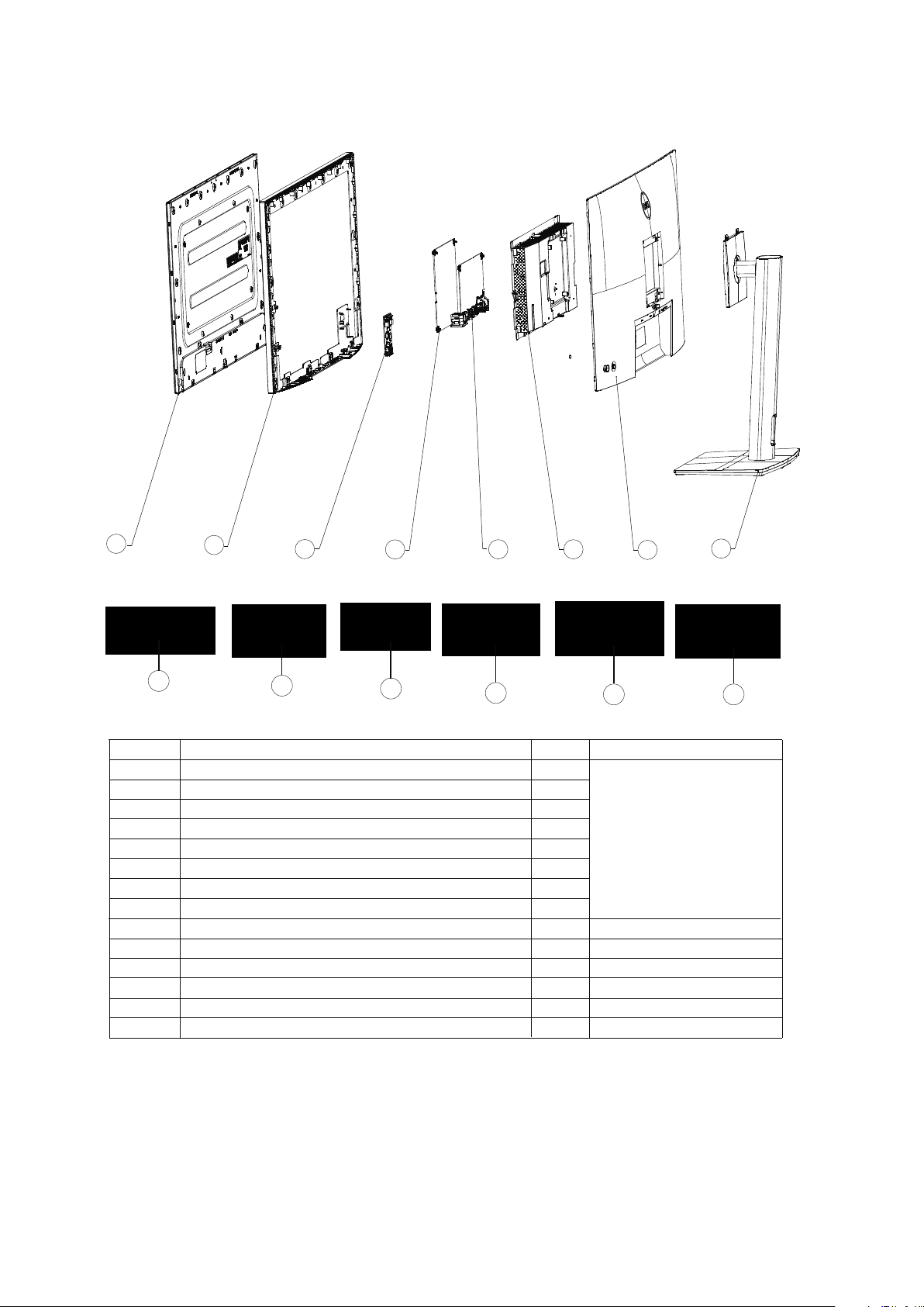
2. Exploded view diagram with list of items
1
8
2
10
3
4
11
5 6
12
7
13
Item Description Q'ty Remark
1
2
4 1
Panel
ASSY Middle Frame
PCBA USB BD
PCBA Power BD
PCBA Interface BD
1
1
13
For EMEA Only, not for
15
other regions
6 ASSY Main Chassis 1
ASSY Rear Cover
8 1
11
12
ASSY Stand Base
Power cable
DisplayPort 1.8 M cable
USB-C Gen2 PD3.0 cable (U3023E only)
USB-C Gen2 1.0 M cable (A to C) (U3023E only)
USB-C 1.0 M cable (A to C) (U2723QE/U3223QE only)
USB-C 1.0 M cable (C to C) (U2723QE/U3223QE only)
1 7
1
9
1
10
1
1
1 13
1 14
See “NOTE”
See “NOTE”
See “NOTE”
See “NOTE”
See “NOTE”
See “NOTE”
8
14
NOTE:
For replacement of power cord, connectivity cable and external power supply (if applicable), contact Dell:
1. Go to https://www.dell.com/support.
2. Verify your country or region in the Choose A Country/Region drop-down menu at the bottom-right corner of the page.
3. Click Contact Us next to the country dropdown.
4. Select the appropriate service or support link based on your need.
5. Choose the method of contacting Dell that is convenient for you.
Page 4
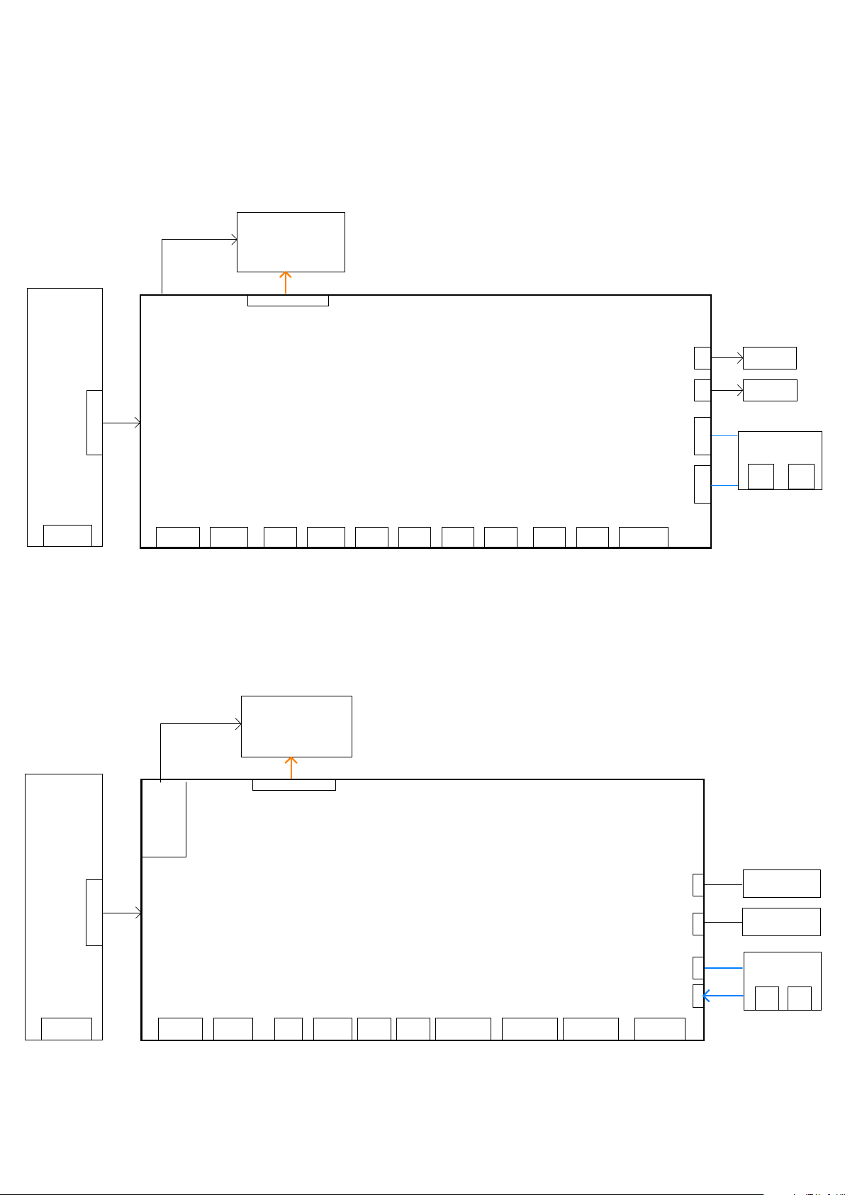
U2723QE&U3223QE
3. Wiring Connectivity Diagram
Panel 3840*2160
HDR400
KB1
KB2
Joystic BD
LED BD
Power BD
U3023E
AC In
Interface Board
HDMI2.0 In DP1.4 In Type-C1 DP1.4 out USB3.0
HDMI DP1 USBC1 DP2 Line-out USBC2 USB1 USB2 USB3 USB4 LAN1
Panel 2560*1600
LED
Driver
BD
LOUT 1
Type-C2 USB3.0
USB3.0
Down 1
Down 2
Down 3
USB3.0
Down 4
RJ45
USB board
USBC
USB3.0
Down 6
Down 5
Power BD
HDMI DP1
Interface Board
USB3.0 Down3Type-C2 USB3.0 Down1Line-out
2nwoD 0.3BSUtuo 2.1PD1 C epyTnI 4.1PDnI 4.1IMDHAC In
USBC1 DP2 Line-out USBC2 USB1 USB2 USB3 LAN1
RJ45
Joystick board
LED board
USB board
USBC
USB3.0
Down5
Down4
Page 5
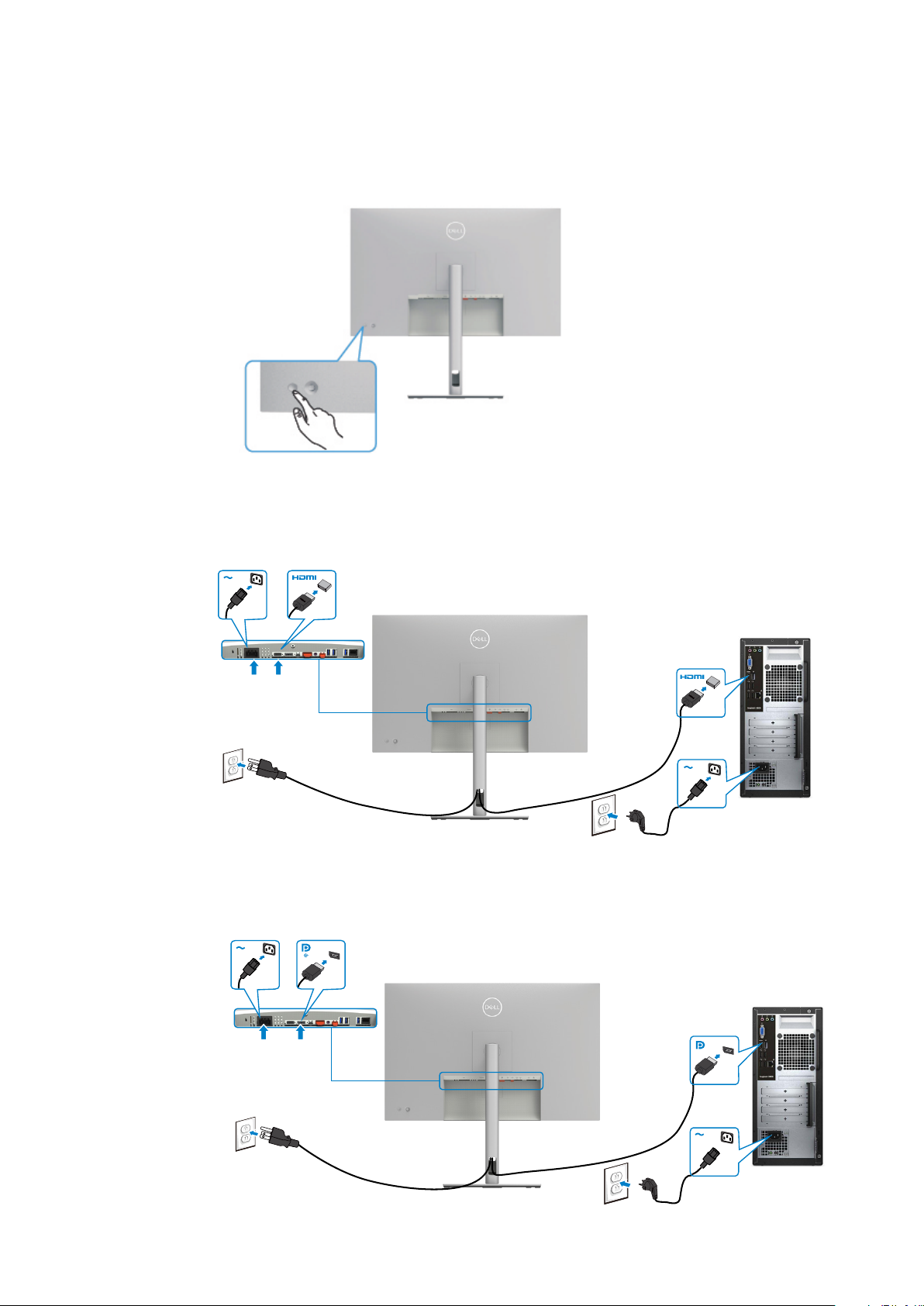
4. How to connect and disconnect power cable/ connectivity cable
WARNING: To change power cable/ connectivity cable, switch off power before unplugging the cable and replugging in required
cable.
Connecting the HDMI Cable (optional)
Connecting the DP Cable
Page 6
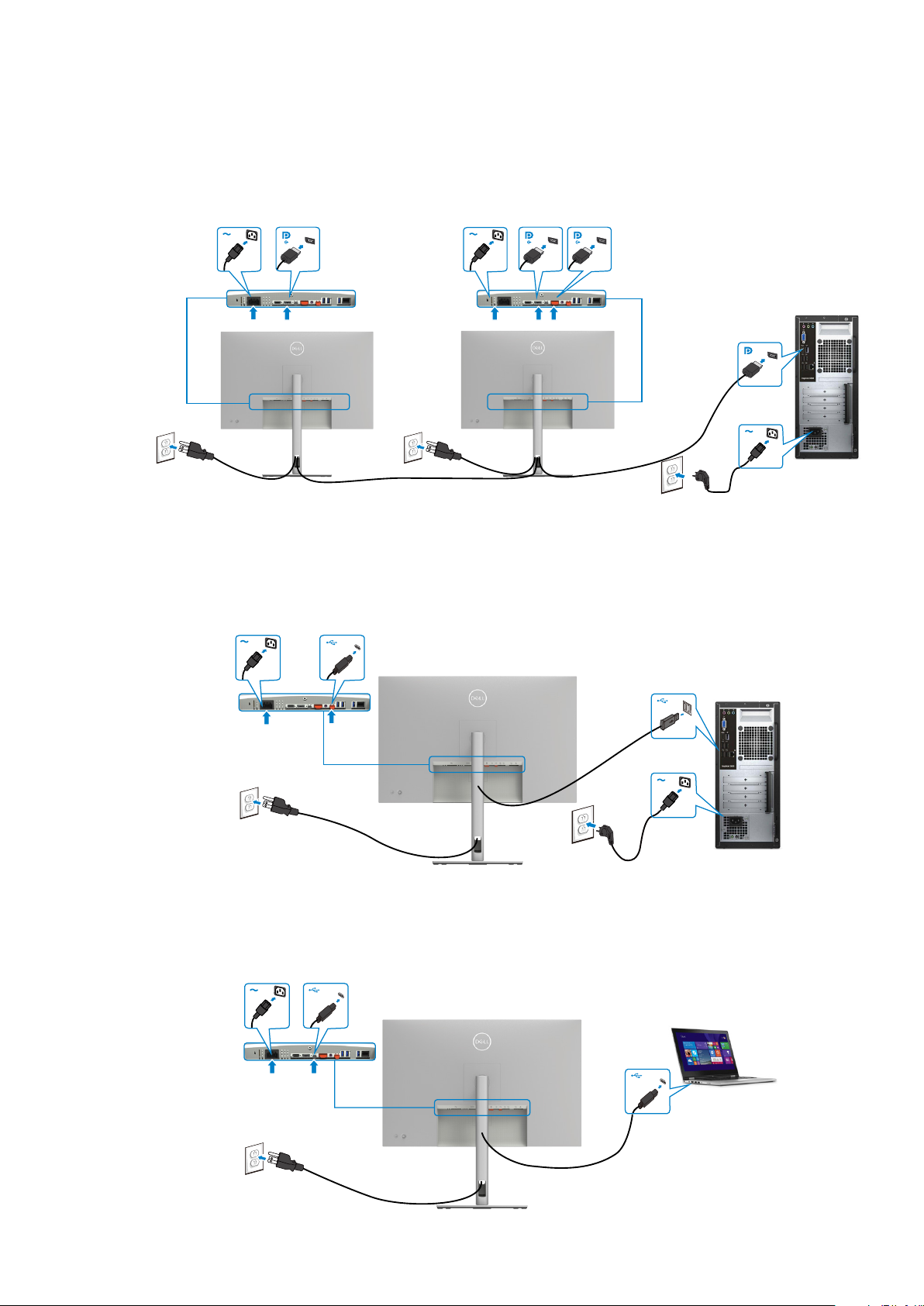
4. How to connect and disconnect power cable/ connectivity cable
Connecting the monitor for DP Multi-Stream Transport (MST) function
Connecting the USB-C Cable (A to C)
Connecting the USB-C Cable (C to C)
Page 7
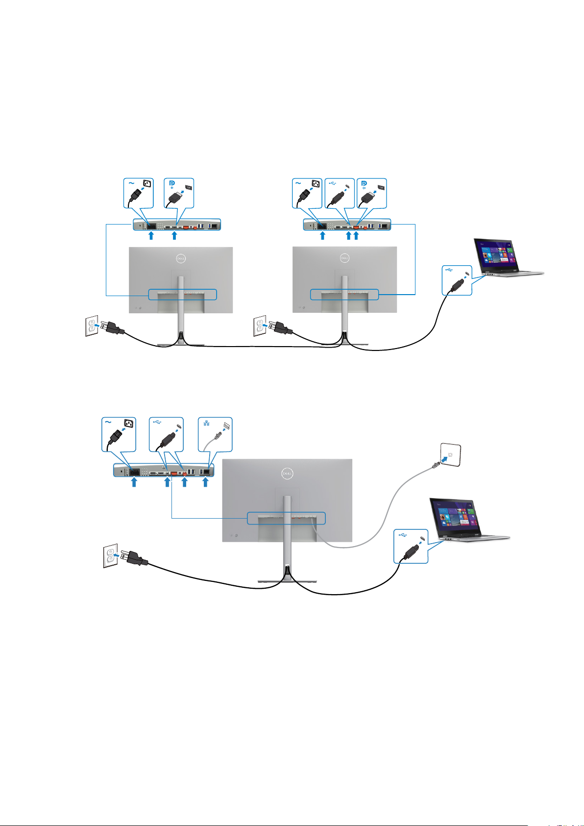
4. How to connect and disconnect power cable/ connectivity cable
Connecting the Monitor for USB-C Multi-Stream Transport (MST) Function
Connecting the Monitor for RJ45 Cable (optional)
Page 8
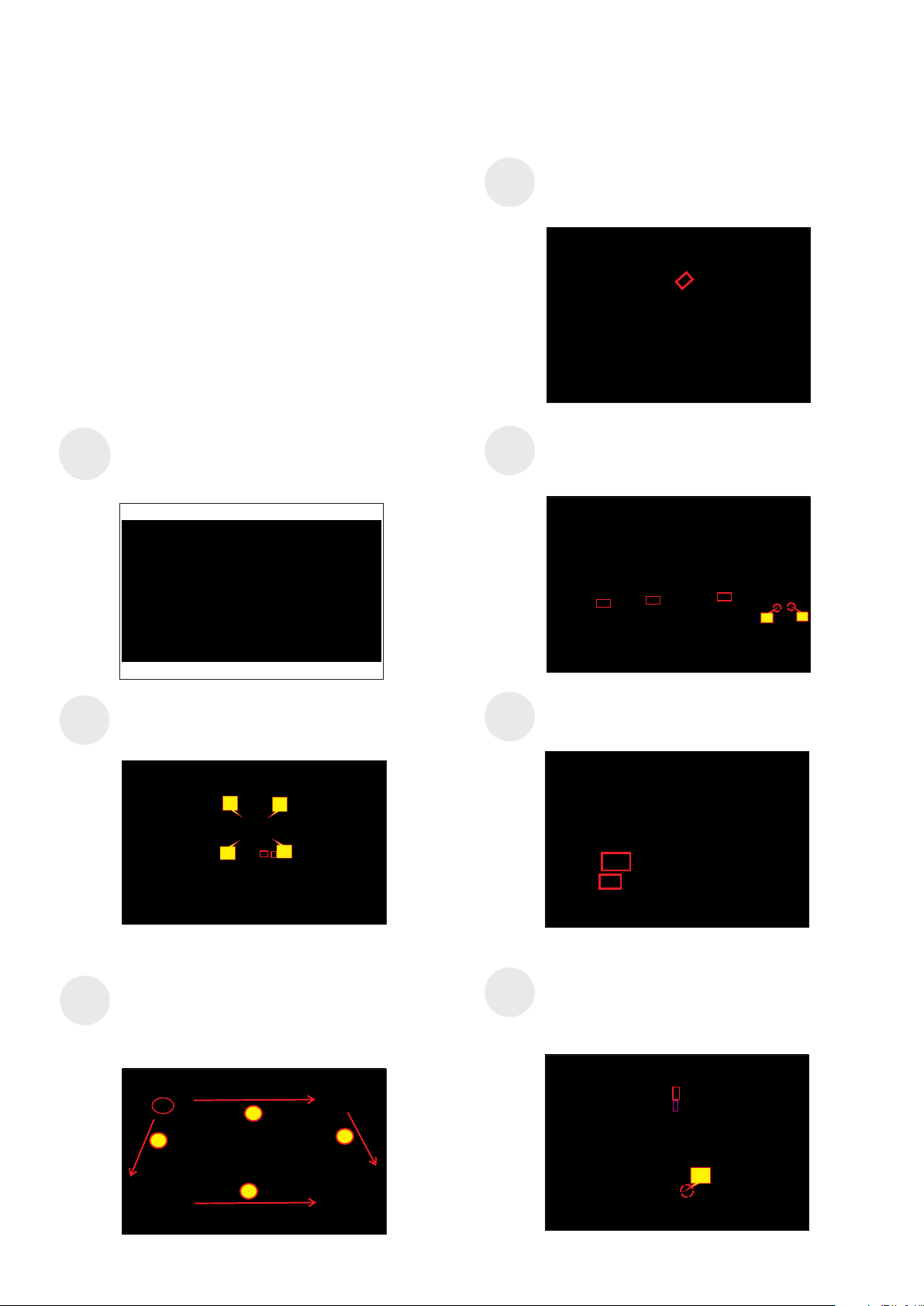
5. Disassembly and Assembly Procedures
NOTE:
This “Disassembly and Assembly Procedures” is for EMEA only,
not for other regions. Please note that Dell will deem warranty void
if any disassembly is done on the monitors.
Tool Required:
List the type and size of the tools that would typically can be
used to disassemble the product to a point where components
and materials requiring selective treatment can be removed.
Tool Description:
- Screwdriver(Phillip head) #1
- Screwdriver(Phillip head) #2
- Penknife
- Soldering iron and absorber
4.1 Disassembly Procedures(U3223QE for example):
Remove the monitor stand base:
S1
S1
1. Place the monitor on a soft cloth or cushion.
2. Press and hold the stand-release button.
3. Lift the stand up and away from the monitor.
S4
S5
Lift the rear cover up carefully. Disconnect the
joystick key cable from the connector of the interface
board, and then remove the rear cover and put it
aside for later disassembling.
Use a Philips-head screwdriver to remove 2pcs
screw for unlocking the key board, then tear off the
tapes and release the key board.
(No.1~2 screw size=M2x2.4, Torque=0.8~1kgfxcm)
S2
S3
Use a Philips-head screwdriver to remove 4pcs
screws for unlocking mechanisms. Remove DP caps.
(No.1~4 screw size=M4x11; Torque=11± 1kgfxcm)
2
4
Wedge your fingers between rear cover and the
middle bezel on the corners of the top side of the
monitor to release the rear cover, then use one hand
to press the middle bezel, the other hand to pull up
carefully the rear cover in order of arrow preference
for unlocking mechanisms of rear cover.
3
1
S6
S7
1
2
Tear off 1pcs aluminum foil for unfixing the bracket,
then tear off 1pcs acetate tape for uncovering the
LVDS connector .
Use a Philips-head screwdriver to release one screw
for unlocking the USB board, and disconnect the two
cables, then release the USB board from the hooks
of the middle bezel.
(No.1screw size=M3x6, Torque=4±0.5kgfxcm)
1
2
3
2
1
Page 9
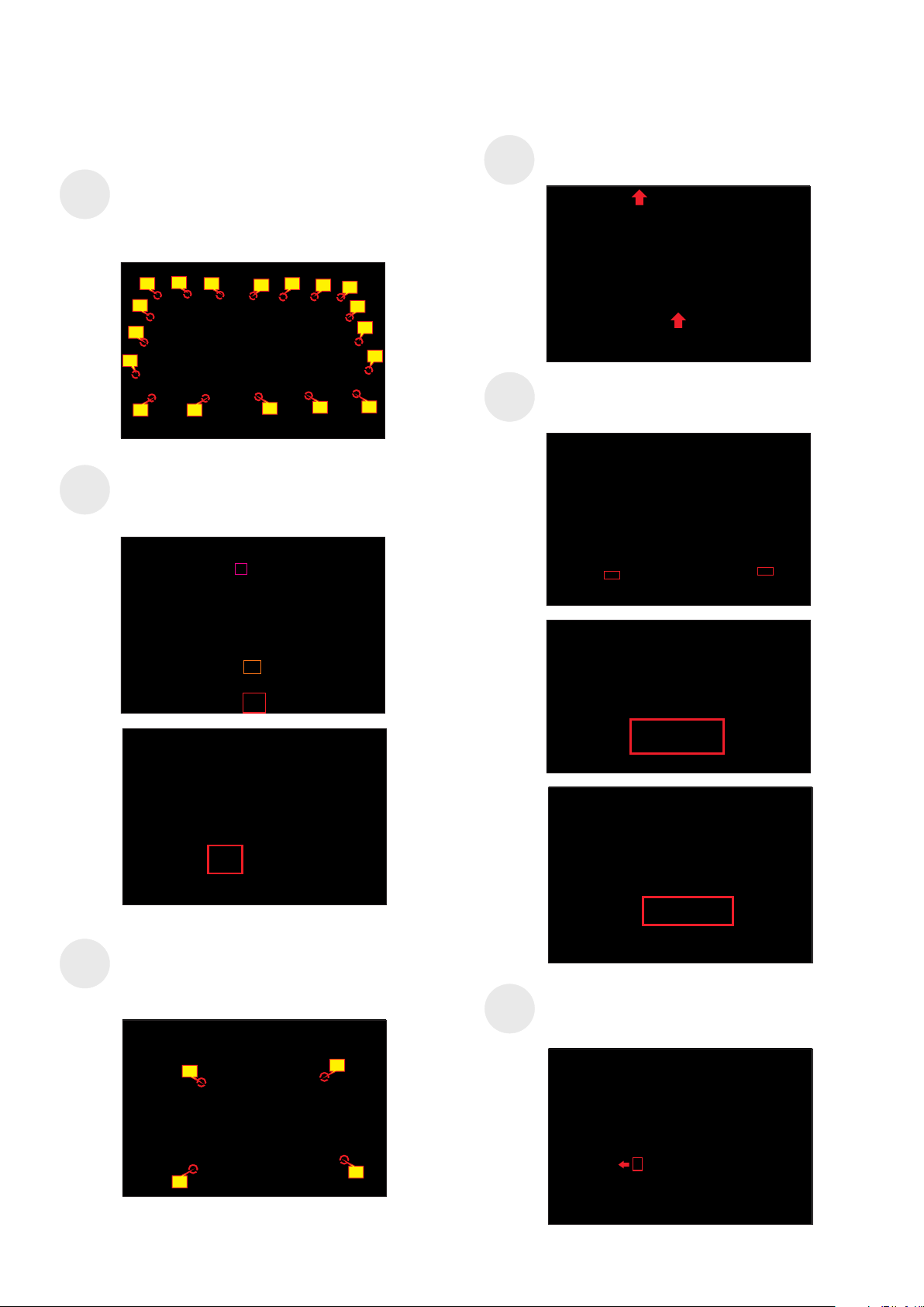
5. Disassembly and Assembly Procedures
S8
S9
Use a Philips-head screwdriver to remove
18(13+5)pcs screws for unlocking the middle bezel
with the panel module.
(No.1~13 screw size=M3x5, Torque=5±0.5kgfxcm;
No.13~18 screw size=M3x4.5, Torque=5±0.5kgfxcm)
7
5 8 9
11
2
10
15 17
14
61
4
13
3
12
18
16
Disconnect the two panel lamp cables from the
connectors of the panel. Disconnect the LED cable
from the connector of the interface board.
S11
S12
Lift up the middle bezel, and then put it on a cushion
foam for later disassembling.
Tear off the tape on the middle bezel for releasing the
LED cable, and then tear off the mylar tape to release
the LED board for the hooks of the middle bezel.
S10
U.se a Philips-head screwdriver to remove 4pcs
screws for unlocking the bracket chassis module
with the panel
(No.1~4 Screw size= M3x5, Torque=5±0.5kgfxcm)
3
2
1
4
S13
Move up the bracket, then push the earing-lock and
disconnect the LVDS cable away from the connectors
of the panel module.
Page 10
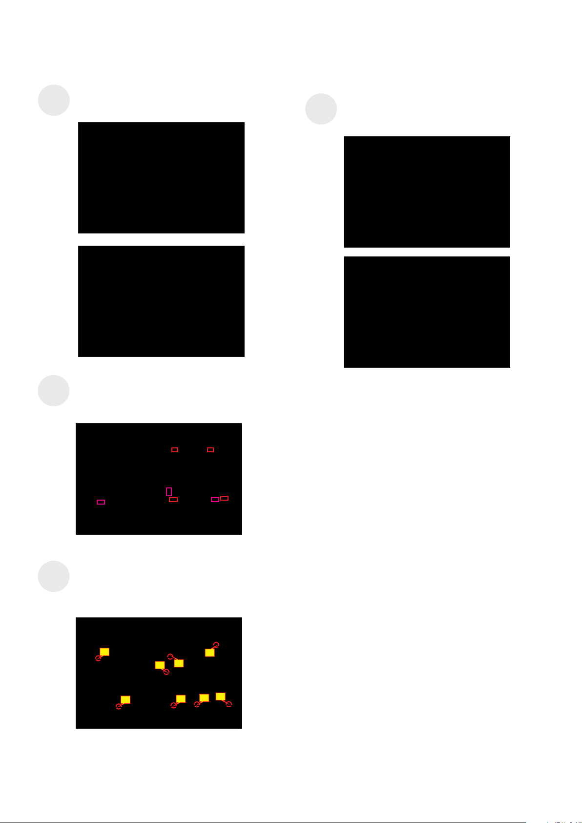
5. Disassembly and Assembly Procedures
S14
S15
Take away the bracket chassis module and then put
the bracket chassis module on a protective cushion.
Release the panel lamp cables from the hooks of the
bracket, then remove the Mylar tape from the hooks
of the bracket.
S17
Remove the power board board and interface
board from the
and then
bracket chassis module carefully,
disconnect all of the cables.
S16
Use a Philips-head screwdriver to remove
8pcs
screws for interface board and power board.
(No.1 screw size=M4x8, Torque=7±1kgfxcm;
No.2~8 screw size=M3x7.5, Torque=7±1kgfxcm)
6
3
8
7
1
2
4
5
Page 11
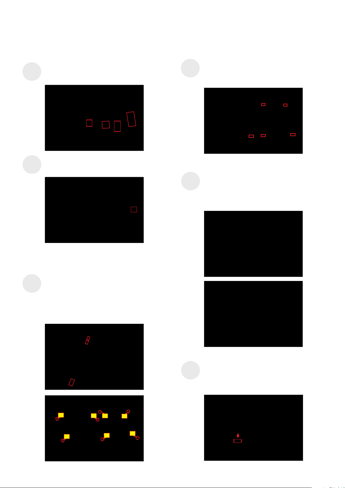
5. Disassembly and Assembly Procedures
5.1 Assembly Procedures:
Place a bracket chassis base on a protective
S1
S2
cushion, then stick 4pcs Silicon sheets on the
positions as the picture below shown.
Take a power board and put the power board into
the bracket chassis, settle the cable to the correct
position.
S4
S5
Take a black mylar to insert the hooks of the bracket
to cover the power board, then tear off the gum
paper of the panel lamp cable and locate the cable
into the hook of the bracket..
Panel preparation: Take out 1pcs panel module from
the carton, remove the protective film by tearing off
the tapes, then examine the panel surface according
to inspection criteria of the panel. Turn over the
panel module to place the screen faced down for
later assembling.
S3
Take a interface board, connect 1pcs LVDS cable and
1pcs panel lamp cable to the connectors of the
interface board, then connect the cable of the power
board with interface board. Turn over the interface
board and locate it to the bracket. Use a Philips-head
screwdriver to tighten 7pcs screws for locking the
interface board and power board.
(No.1 screw size=M4x8, Torque=7.5±0.5kgfxcm;
No.2~7 screw size=M4x8, Torque=7.5±0.5kgfxcm)
6
5
3
2
S6
Move the bracket chassis module close to the panel
module, then connect the LVDS cable to the
connector of the panel module, then turn over the
bracket chassis and put it on the back of the bracket
chassis module.
7
1
4
Page 12
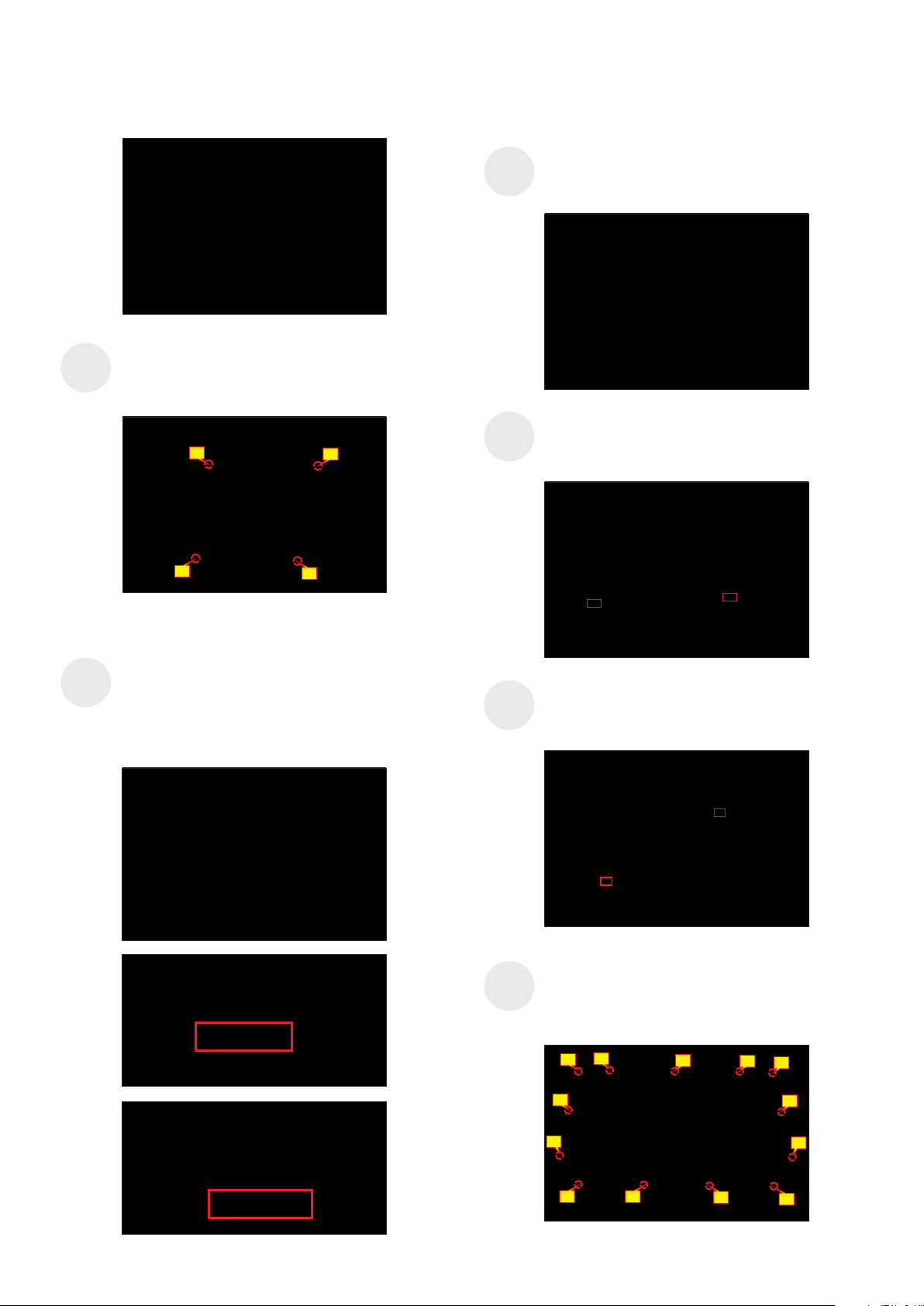
5. Disassembly and Assembly Procedures
Adjust the bracket chassis module, and then u.se a
Philips-head screwdriver to tighten 4pcs screws for
S7
locking the bracket chassis module with the panel
(No.1~4 Screw size= M3x5, Torque=5±0.5kgfxcm)
1
1
S9
S10
Move the middle bezel with the LED board close to
the panel unit, then assemble the middle bezel with
the front bezel and panel module.
Tear off the release paper of the adhesive tape on
the back of the LED cable, then settle and fix the
LED cable on the back of the panel module.
S8
1
4
Take 1pcs LED key board and 1pcs middle bezel,
then put the middle bezel into a fixture jip to fix the
middle bezel. Tear off the gum on the back of the
board, and then paste the LED board on the correct
position of the middle bezel, then paste 1pcs mylar
tape to cover the LED board as the picture below
shown.
S11
S12
Connect the panel lamp cable to the connector of
the panel module. Connect the LED cable to the
connector of the interface board.
Use a Philips-head screwdriver to tighten 13pcs
screws for locking the middle bezel with the panel
module.
(No.1~13 screw size=M3x5, Torque=5±0.5kgfxcm)
7
5
2
8
13
12
1
6
4
3
9
11
10
Page 13
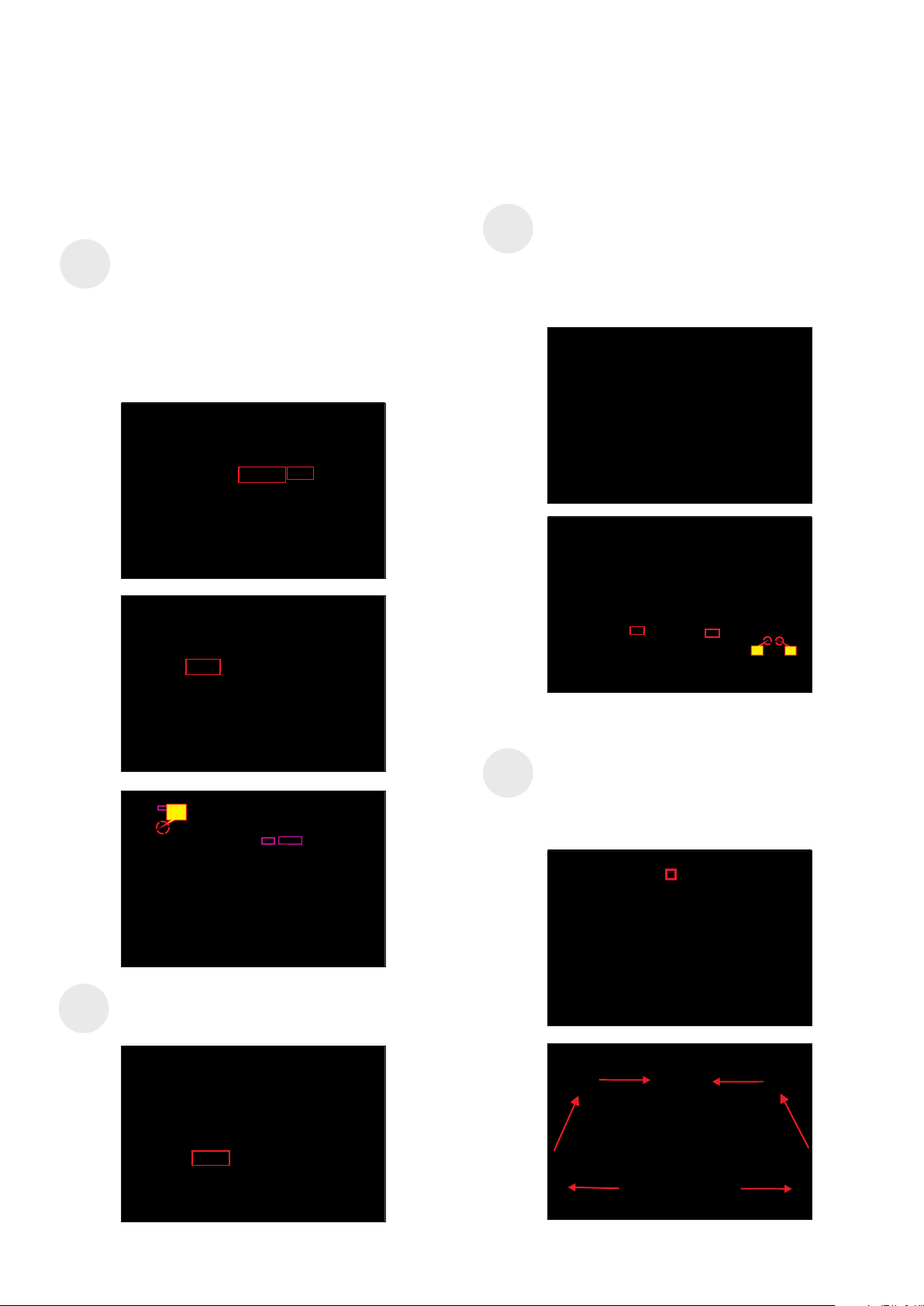
5. Disassembly and Assembly Procedures
S13
Take 1pcs USB board, 2pcs cables and 1pcs
conductive foam. Connect the 2pcs cables to the
connectors of the Usb board, then turn over the
board and paste the conductive foam on the back of
the USB board, and then locate the USB board into
the correct position of the middle bezel. Use a
Philips-head screwdriver to tighten 1pcs screw for
locking the USB unit with the middle bezel, then
connect the two USB cables to the connectors of
interface board.
(No.1 screw size=M3x6, Torque=4±0.5kgfxcm)
S15
Take 1pcs joystick key and 1pcs OSD board,
assemble the joystick key with the OSD board.
Locate the board to the correct position of the rear
cover, then use a Philips-head screwdriver to tighten
2pcs screws for locking the board with rear cover.
Tear off the tape papers on the back of the cable,
and then fix the key cable with tapes.
(No.1~2 screw size=M2x2.4, Torque=0.9±0.1kgfxcm)
S14
1
Paste 1pcs aluminum foil to fix the bracket on the
specific position as the picture below shown.
S16
2
1
Move the assembled rear cover close to the panel
unit, then connect the joystick key cable to the
connector of interface board. Put down the rear
cover and push the rear cover on the positions
marked as the picture below shown for
mechanisms engagement.
Page 14
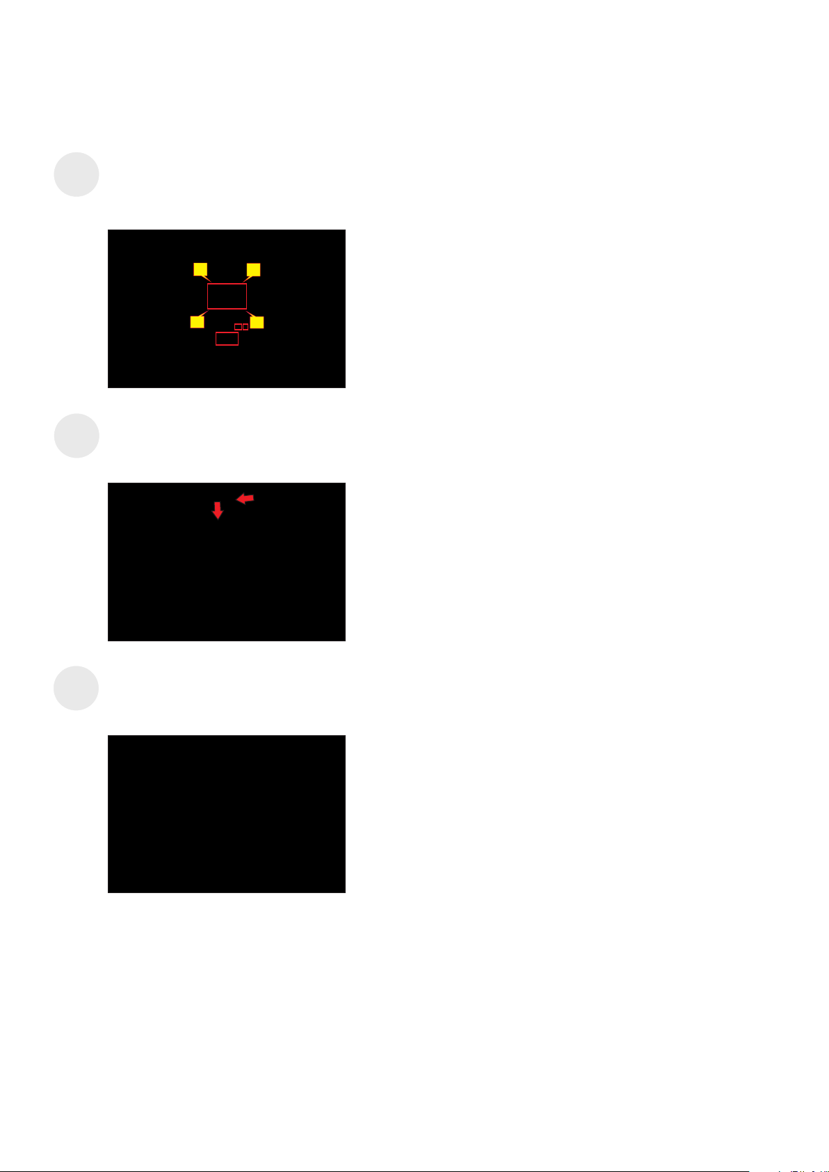
S17
5. Disassembly and Assembly Procedures
Use a Philips-head screwdriver to tighten 4pcs
screws for locking the rear cover with the unit. Stick
two pieces of label on the specific positions, then
insert 2pcs DP out Caps into the DP out connectors.
(No.1~4 screw size=M4x11; Torque=11±1kgfxcm)
S18
S19
2
4
Take a stand base close to the monitor. Fit the two
tabs on the upper part of the stand into the grooves,
and then lower the stand so that the monitor
mounting area snaps onto the stand.
Lift up the monitor to check the gap between the
front bezel and the panel, then provide power supply
and a video signal to the monitor , then turn on the
monitor for functionality check.
3
1
Page 15
6. Trouble Shooting Instructions
Self-Test
Your monitor provides a self-test feature that allows you to check whether your
monitor is functioning properly. If your monitor and computer are properly connected
but the monitor screen remains dark, run the monitor self-test by performing the
following steps:
1. Turn o both your computer and the monitor.
2. Unplug the video cable from the back of the computer. To ensure proper Self-Test
operation, remove all digital and the analog cables from the back of computer.
3. Turn on the monitor.
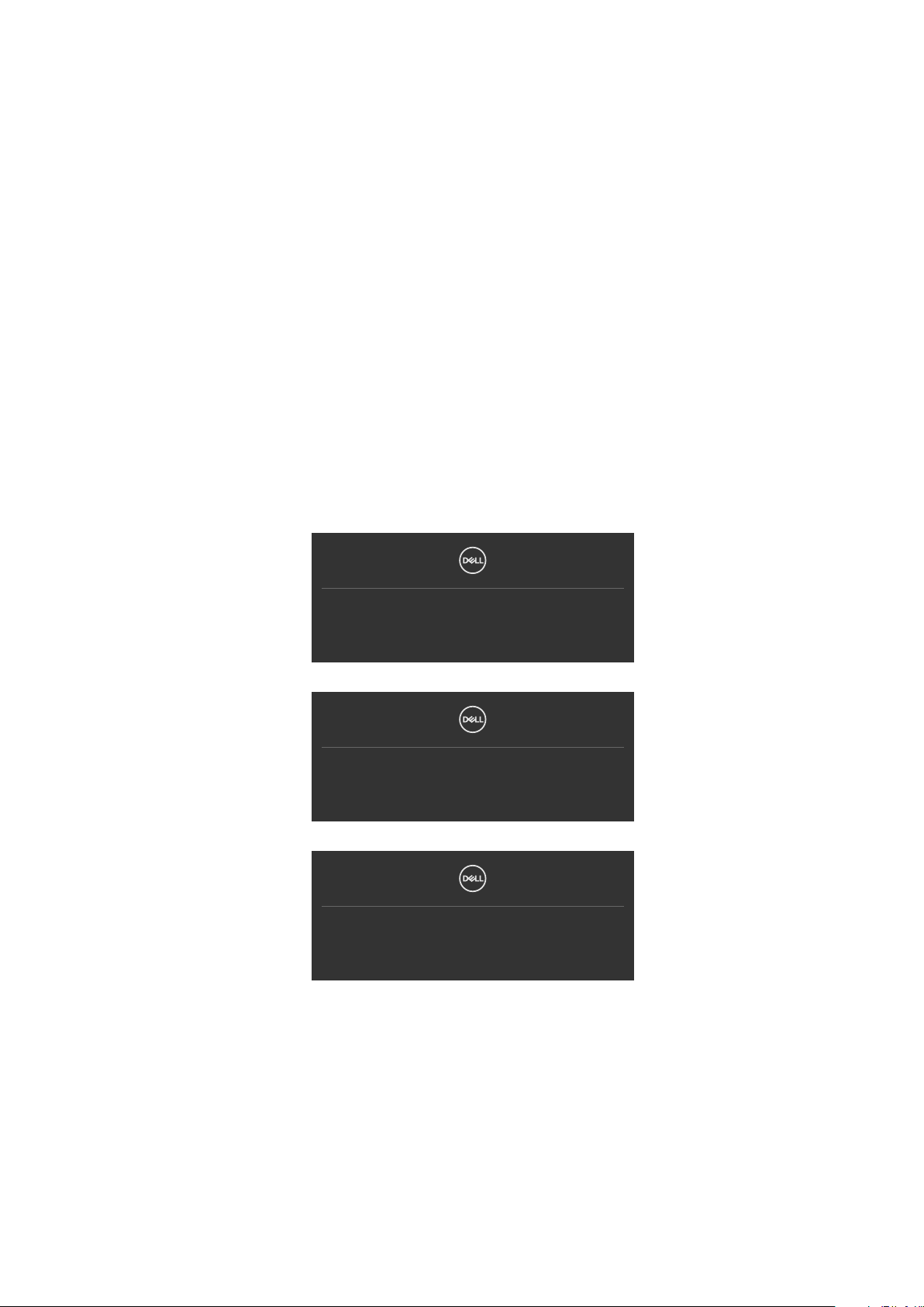
The floating dialog box should appear on-screen (against a black background), if the
monitor cannot sense a video signal and is working correctly. While in self-test mode,
the power LED remains white. Also, depending upon the selected input, one of the
dialogs shown below will continuously scroll through the screen.
No DP Cable
The display will go into Standby Mode in 4 minutes.
www.dell.com/U3023E/U2723QE/U3223QE
or
No HDMI Cable
The display will go into Standby Mode in 4 minutes.
www.dell.com/U3023E/U2723QE/U3223QE
or
No USB-C Cable
The display will go into Standby Mode in 4 minutes.
www.dell.com/U3023E/U2723QE/U3223QE
4. This box also appears during normal system operation if the video cable becomes
disconnected or damaged.
5. Turn o your monitor and reconnect the video cable; then turn on both your
computer and the monitor.
If your monitor screen remains blank after you use the previous procedure, check your
video controller and computer, because your monitor is functioning properly.
Page 16
6. Trouble Shooting Instructions
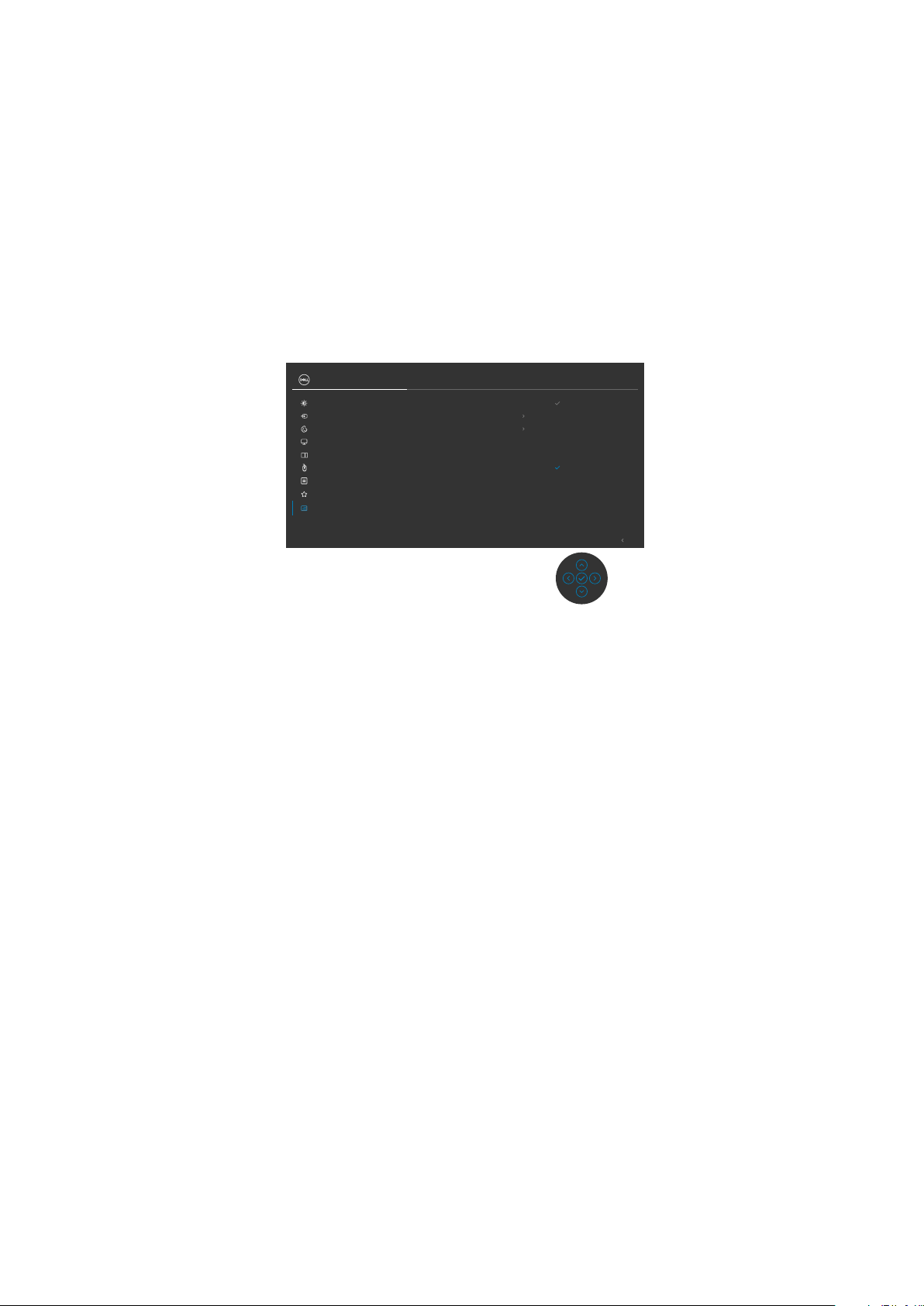
Built-in diagnostics
Your monitor has a built-in diagnostic tool that helps you determine if the screen
abnormality you are experiencing is an inherent problem with your monitor, or with your
computer and video card.
UltraSharp 30/27/32 Monitor
Brightness/Contrast
Input Source
Color
Display
PIP/PBP
USB
Menu
Personalize
Others
Display Info
DDC/CI On
LCD Conditioning
Firmware M3T101
Service Tag CN073K0
Self-Diagnostics Select
Reset Others
Factory Reset
Select
O
ENERGY STAR
®
Exit
To Run the Built-in diagnostics:
1. Ensure that the screen is clean (no dust particles on the surface of the screen).
2. Select OSD items of Self-Diagnostics in Others feature.
3. Press the joystick button to start the diagnostics. A gray screen is displayed.
4. Observe if the screen has any defects or abnormalities.
5. Toggle the joystick once again until a red screen is displayed.
6. Observe if the screen has any defects or abnormalities.
7. Repeat steps 5 and 6 until the screen displays green, blue, black, and white
colors. Note any abnormalities or defects.
The test is complete when a text screen is displayed. To exit, toggle the joystick control
again.
If you do not detect any screen abnormalities upon using the built-in diagnostic tool,
the monitor is functioning properly. Check the video card and computer.
Page 17

6. Trouble Shooting Instructions
Common problems
The following table contains general information about common monitor problems you
might encounter and the possible solutions:
Common
symptoms
No Video/
Power LED off
No Video/
Power LED on
Missing Pixels LCD screen has
Stuck-on Pixels LCD screen has
Brightness
Problems
Safety Related
Issues
What you
experience
No picture •Ensure that the video cable connecting the
No picture or no
brightness
spots
bright spots
Picture too dim
or too bright
Visible signs of
smoke or sparks
Possible solutions
monitor and the computer is properly connected
and secure.
•Verify that the power outlet is functioning
properly using any other electrical equipment.
•Ensure that the power button is depressed fully.
•Ensure that the correct input source is selected
in the Input Source menu.
•Increase brightness and contrast controls via
OSD.
•Perform monitor self-test feature check.
•Check for bent or broken pins in the video cable
connector.
•Run the built-in diagnostics.
•Ensure that the correct input source is selected
in the Input Source menu.
•Cyclepoweron-off.
•Pixelthatispermanentlyoffisanaturaldefect
that can occur in LCD technology.
•FormoreinformationonDellMonitorQualityand
Pixel Policy, see Dell Support site at:
https://www.dell.com/pixelguidelines.
•CyclepowerOn-Off.
•Pixelthatispermanentlyoffisanaturaldefect
that can occur in LCD technology.
•FormoreinformationonDellMonitorQualityand
PixelPolicy, see Dell Support site at:
https://www.dell.com/pixelguidelines.
•Reset the monitor to factory settings.
•Adjust brightness and contrast controls via OSD.
•Do not perform any troubleshooting steps.
•Contact Dell immediately.
Page 18

6. Trouble Shooting Instructions
Common
symptoms
Intermittent
Problems
Missing Color Picture missing
Wrong Color Picture color
Image retention
from a static
image left on
the monitor for
a long period of
time
What you
experience
Monitor
malfunctions on
& off
color
not good
Faint shadow
from the static
image displayed
appears on the
screen
Possible solutions
•Ensure that the video cable connecting the
monitor to the computer is connected properly
and is secure.
•Resetthemonitortofactorysettings.
•Perform monitor self-test feature check to
determine if the intermittent problem occurs in
self-test mode.
•Perform monitor self-test.
•Ensure that the video cable connecting the
monitor to the computer is connected properly
and is secure.
•Check for bent or broken pins in the video cable
connector.
•Try dierent Preset Modes in Color settings
OSD.
•Adjust R/G/B value under Custom Color in Color
menu OSD.
•Change the Input Color Format to RGB or
YCbCr in the Color settings OSD.
•Run the built-in diagnostics.
•Set the screen to turn o after a few minutes
of screen idle time. These can be adjusted in
Windows Power Options or Mac Energy Saver
setting.
•Alternatively, use a dynamically changing
screensaver.
Page 19

6. Trouble Shooting Instructions
Product specific problems
Problem What you
experience
Screen image is
too small
Cannot adjust
the monitor
with the
buttons on the
front panel
No Input Signal
when user
controls are
pressed
The picture
does not fill the
entire screen
No image
when using DP
connection to
the PC
Image is
centered on
screen, but
does not fill
entire viewing
area
OSD does not
appear on the
screen
No picture, the
LED light is
white
The picture
cannot fill the
height or width
of the screen
Black screen •Verify which DP standard (DP 1.1a or DP 1.4) is
Possible solutions
•Check the Aspect Ratio setting in the Display
menu OSD.
•Reset the monitor to factory settings.
•Turn o the monitor, unplug the monitor power
cable, plug it back, and then turn on the monitor.
•Check the signal source. Ensure the computer
is not in the power saving mode by moving the
mouse or pressing any key on the keyboard.
•Check whether the signal cable is plugged
in properly. Connect the signal cable again, if
necessary.
•Reset the computer or video player.
•Due to dierent video formats (aspect ratio) of
DVDs, the monitor may display in full screen.
•Run the built-in diagnostics.
your Graphics Card certied to. Download and
install the latest graphics card driver.
•Some DP 1.1a graphics card cannot support
DP 1.4 monitors. Go to OSD menu, under Input
Source selection, press and hold DP select
joystick key for 8 seconds to change the monitor
setting from DP 1.4 to DP 1.1a.
Page 20

6. Trouble Shooting Instructions
Problem What you
experience
No image when
Black screen •Verify if the USB-C interface of the device can
using USB-C
connection
to computer,
laptop, and so
on
No charging
No charging •Verify if the device can support one of 5 V/9 V/
when using
USB-C
connection
to computer,
laptop, and so
on
Intermittent
charging when
Intermittent
charging
using USB-C
connection to
computer,
laptop, and so
on
No image when
using USB-C
MST
No network
connection
Black screen or
nd
DUT is not
2
Prime mode
Network
dropped or
Intermittent
Possible solutions
support DP alternate mode.
•Verify if the device required more than 90 W
power charging.
•USB-C interface of device cannot support DP
alternate mode.
•Set Windows to Projection mode.
•Ensure that the USB-C cable is not damaged.
15 V/20 V charging proles.
•Verify if the Notebook requires a >90 W power
adaptor.
•If the Notebook requires a >90 W power
adaptor, it may not charge with the USB-C
connection.
•Ensure that you use only Dell approved adapter
or the adapter that comes with the product.
•Ensure that the USB-C cable is not damaged.
•Check if the maximum power consumption of
device is over 90 W.
•Ensure that you use only Dell approved adapter
or the adapter that comes with the product.
•Ensure that the USB-C cable is not damaged.
•USB-C input, Go to OSD menu, under Display
Info check the Link Rate is HBR2 or HBR3, if
Link Rate is HBR2, suggest to use USB-C to DP
cable to turn on MST.
•Do not toggle O/On the power button when
network is connected, keeps the power button
On.
Page 21

6. Trouble Shooting Instructions
Problem What you
experience
The LAN port is
not functioning
OS setting
or cable
connection
issue
nd
U3023E cannot
set to 2560 x
1600 @ 60Hz
in Daisy chain
mode in DP1.2
(DSC Disable)
monitor
2
displayed image
cannot set at
2560 x 1600
@ 60Hz when
set MST On
and USB-C
Prioritization
(High Data
Speed)
rd
3
U3023E
connected as
rd
monitor
3
cannot set to
2560 x 1600 @
60Hz in Daisy
chain mode in
DP1.4 (DSC
Disable)
monitor
displayed image
cannot set at
2560 x 1600
@ 60Hz when
set MST On
and USB-C
Prioritization
(High Data
Speed)
Possible solutions
•Ensure that the latest BIOS and drivers for your
computer are installed on your computer.
•Ensure that the RealTek Gigabit Ethernet
Controller is installed in the Windows Device
Manager.
•If your BIOS Setup has a LAN/GBE Enabled/
Disabled option, make sure it is set to Enabled.
•Ensure that the Ethernet cable is connected
securely on the monitor and the hub/router/
rewall.
•Check the status LED of the Ethernet cable to
conrm connectivity. Re-connect both ends of
the Ethernet cable if the LED is not lit.
•First power o the Computer and unplug the
Type-C cable and power cord of the monitor.
Then, power on the computer, plug in the
monitor power cord and Type-C cable.
•Switch USB-C Prioritization from High Data
Speed to High Resolution. (USB speed reduce
to 2.0)
•Switch PC that supported DP1.4
•Switch USB-C Prioritization from High Data
Speed to High Resolution. (USB speed reduce
to 2.0)
Page 22

6. Trouble Shooting Instructions
Problem What you
experience
U3023E
connected as
rd
monitors
3
displayed
image at lower
resolution in
DP1.4 (DSC
Enable)
Three U3023E
monitors
connected in
daisy chain,
rd
3
displayed
image at lower
resolution when
set MST On
and USB-C
Prioritization
(High Data
Speed)
nd
monitor
2
(U3023E) no
displayed image
when 1
st
monitor
(non-DSC)
connected
to Discrete
Graphic Card
(E.g Nvidia)
with DSC
Enable
U3023E as 2
monitor cannot
display 2560
x 1600 image
when 1
st
monitor
(non-DSC)
connected to
Intel Graphic
Card with DP1.4
(DSC Enable)
Two monitors
connected in
Daisy chain,
2nd monitor
U3023E no
displayed image
when set MST
On and USB-C
Prioritization
(High Data
Speed)
nd
Two monitors
connected in
Daisy chain,
nd
monitor
2
U3023E cannot
displayed 2560
x 1600 image
when set MST
On and USB-C
Prioritization
(High Data
Speed)
Possible solutions
•Press “Windows” + “P” key, select “second
screen only”
•Goto Display setting, select 2560 x 1600
st
•Connect U3023E as 1
•Connect U3023E as 1
Monitor
st
Monitor
Page 23

6. Trouble Shooting Instructions
Problem What you
experience
OSD lagging
when navigating
menu
2 or 3 monitors
connected in
daisy chain
when MMS
is On, OSD
lagging during
menu navigation
OSD no
response
2 or 3 monitors
connected in
daisy chain
when MMS is
On, no OSD
response during
menu navigation
response during
menu navigation
Can’t adjust
Brightness/
Contrast
through
Dell Display
Manager
(DDM)
2 or 3 monitors
connected in
daisy chain
when MMS
is On, some
functions of
nd
the 2
or 3rd
monitors may
not work on
DDM
U3023E as
nd
monitor
2
no displayed
image when 1
monitor with
USB-C cable
connected
to Nvidia
Graphic Card
(DSC Enable)
with Salomon
Two monitors
connected in
Daisy chain,
st
2nd monitor
U3023E no
displayed image
when set MST
On and USB-C
Prioritization
(High Data
Speed)
docking
Possible solutions
•Set Multi-Monitor Sync (MMS) turn o
•Or Slow the OSD navigating speed to 1 second
•Set Multi-Monitor Sync (MMS) turn o
•Set Multi-Monitor Sync (MMS) turn o
•Or adjust Brightness/contrast through OSD
•In the BIOS menu set to disable” discrete
graphics controller direct output mode”
•Without docking
Page 24

6. Trouble Shooting Instructions
Problem What you
experience
U3023E
connected as
nd
monitor
2
cannot set to
2560 x 1600 @
60Hz in Daisy
chain mode in
DP1.4 (DSC
Disable)
Two monitors
connected in
Daisy chain, 1st
monitor(nonDSC) and
nd
monitor
2
U3023E cannot
set to 2560 x
1600 @ 60Hz
when set MST
On and USB-C
Prioritization
(High
Resolution)
3x U3023E
connected in
MST mode
encountered
flicker issue
3x U3023E
connected in
MST mode
encountered
flicker issue for
1 second during
Shutdown,
Reboot,
Unplug/plug,
Sleep & Wakeup
st
monitor
1
(Non DSC)
connected
nd
monitor
2
U3023E (DSC)
cannot reach
native resolution
nd
monitor
for 2
Ethernet not
working
st
1
monitor
(Non DSC)
connected
nd
monitor
2
U3023E (DSC)
cannot reach
native resolution
nd
monitor
for 2
Ethernet not
connected
Possible solutions
•Connect U3023E as 1
st
Monitor
•Intel Graphic card driver limitation
•Intel Graphic card driver limitation
•Connect U3023E as 1
st
Monitor
•Install Ethernet Driver 10.45.20.
Page 25

6. Trouble Shooting Instructions
Problem What you
experience
3 Soundbar
unit not
working when
connected
to 3 U3023E
monitor
3 soundbars
unit connected
individually
to 3 U3023E
monitor,
soundbar not
working via DP/
HDMI
3x U3023E
connected in
MST mode DSC
disable and High
Data Speed
encountered
hang five
minutes issue
Three monitors
connected in
Daisy chain,
st
monitor
1
connect USB-C
cable with
platform and 2
rd
and 3
monitor
with DP cable
when set MST
On and USB-C
Prioritization
(High Data
Speed) and
DSC Disable
Restart
platform or
unplug and plug
USB-C cable
encounter hang
five minutes
issue
Possible solutions
•USB Topology limitation to 2.
•Connect 2 soundbar unit individually to 2
U3023E monitor
•Connect 2 U3023E monitor at DSC disable and
USB-C Prioritization switch to High Data Speed,
Or
•Connect 3 U3023E monitor at DSC disable and
USB-C Prioritization switch to High Resolution
nd
Page 26

6. Trouble Shooting Instructions
Universal Serial Bus (USB) specific problems
Specific
symptoms
USB interface is
not working
Super speed
USB 3.2 Gen2
interface is
slow.
Wireless USB
peripherals stop
working when a
USB 3.0 device
is plugged in
USB is not
working
What you
experience
USB peripherals
are not working
Super speed
USB 3.2 Gen2
peripherals
working slowly
or not working
at all
Wireless USB
peripherals
responding
slowly or only
working as
the distance
between itself
and its receiver
decreases
No USB
functionalities
Possible solutions
•Check that your display is turned ON.
•Reconnect the upstream cable to your
computer.
•Reconnect the USB peripherals (downstream
connector).
•Turn o the monitor and turn it on again.
•Reboot the computer.
•Certain USB devices such as portable hard
drives require higher power source; connect the
drive to the computer directly.
•Check that your computer is USB 3.0-capable.
•Some computers have USB 3.0, USB 2.0, and
USB 1.1 ports. Ensure that the correct USB port
is used.
•Reconnect the upstream cable to your
computer.
•Reconnect the USB peripherals (downstream
connector).
•Reboot the computer.
•Increase the distance between the USB 3.0
peripherals and the wireless USB receiver.
•Position your wireless USB receiver as close as
possible to the wireless USB peripherals.
•Use a USB-extender cable to position the
wireless USB receiver as far away as possible
from the USB 3.0 port.
Refer to input source and USB pairing table.
 Loading...