

Dell Storage Center SCv2000, Storage Center SCv2020, SCv2000, SCv2020 Deployment Manual

Dell Storage Center
SCv2000 and SCv2020 Storage System
Deployment Guide

Notes, Cautions, and Warnings
NOTE: A NOTE indicates important information that helps you make better use of your computer.
CAUTION: A CAUTION indicates either potential damage to hardware or loss of data and tells you
how to avoid the problem.
WARNING: A WARNING indicates a potential for property damage, personal injury, or death.
Copyright © 2015 Dell Inc. All rights reserved. This product is protected by U.S. and international copyright and
intellectual property laws. Dell™ and the Dell logo are trademarks of Dell Inc. in the United States and/or other
jurisdictions. All other marks and names mentioned herein may be trademarks of their respective companies.
2015 - 07
Rev. A01

Contents
About this Guide.......................................................................................................7
Revision History..................................................................................................................................... 7
Audience................................................................................................................................................ 7
Contacting Dell......................................................................................................................................7
Related Publications.............................................................................................................................. 7
1 About the SCv2000/SCv2020 Storage System............................................... 9
Storage Center Hardware Components.............................................................................................. 9
SCv2000/SCv2020 Storage System............................................................................................... 9
Switches...........................................................................................................................................9
Expansion Enclosures....................................................................................................................10
Storage Center Architecture Options.................................................................................................10
Storage Center Replication...........................................................................................................10
Storage Center Communication.........................................................................................................11
Front-End Connectivity................................................................................................................. 11
Back-End Connectivity..................................................................................................................14
System Administration...................................................................................................................15
SCv2000/SCv2020 Storage System Hardware.................................................................................. 15
SCv2000/SCv2020 Storage System Front-Panel Features and Indicators................................. 15
SCv2000/SCv2020 Back-Panel Features and Indicators.............................................................16
SCv2000/SCv2020 Storage Controller Features and Indicators ................................................17
SCv2000/SCv2020 Drives.............................................................................................................23
SCv2000/SCv2020 Storage System Drive Numbering................................................................23
SC100/SC120 Expansion Enclosure Overview.................................................................................. 24
SC100/SC120 Expansion Enclosure Front-Panel Features and Indicators.................................24
SC100/SC120 Expansion Enclosure Back-Panel Features and Indicators..................................25
SC100/SC120 Expansion Enclosure EMM Features and Indicators............................................ 26
SC100/SC120 Expansion Enclosure Drives.................................................................................. 27
SC100/SC120 Expansion Enclosure Drive Numbering................................................................27
2 Install the Storage Center Hardware.............................................................. 28
Unpack and Inventory the Storage Center Equipment..................................................................... 28
Prepare the Installation Environment.................................................................................................28
Safety Precautions...............................................................................................................................28
Installation Safety Precautions......................................................................................................29
Electrical Safety Precautions.........................................................................................................29
Electrostatic Discharge Precautions.............................................................................................30
General Safety Precautions...........................................................................................................30
Install the Storage System in a Rack...................................................................................................30
3

3 Connect the Front End...................................................................................... 34
Types of Redundancy for Front-End Connections........................................................................... 34
Port Redundancy...........................................................................................................................34
Storage Controller Redundancy................................................................................................... 35
Multipath IO...................................................................................................................................35
Cabling SAN-Attached Host Servers.................................................................................................. 36
Connecting to Fibre Channel Host Servers..................................................................................36
Connecting to iSCSI Host Servers................................................................................................48
Cabling Direct-Attached Host Servers............................................................................................... 57
Preparing Host Servers..................................................................................................................57
SAS Virtual Port Mode................................................................................................................... 58
Two Servers Connected to Dual 12 Gb 4-Port SAS Storage Controllers................................... 58
Four Servers Connected to Dual 12 Gb 4-Port SAS Storage Controllers................................... 59
Two Servers Connected to a Single 12 Gb 4-Port SAS Storage Controller................................ 61
Labeling the Front-End Cables.....................................................................................................62
Cabling the Ethernet Management Port............................................................................................ 63
Labeling the Ethernet Management Cables.................................................................................63
Cabling the Embedded Ports for iSCSI Replication...........................................................................64
Cabling the Replication Port for iSCSI Replication......................................................................64
Cabling the Management Port and Replication Port for iSCSI Replication................................ 65
Cabling the Embedded Ports for iSCSI Host Connectivity................................................................66
Two iSCSI Networks using the Embedded Ethernet Ports on a Storage System with Dual
Fibre Channel Storage Controllers...............................................................................................66
Two iSCSI Networks Using the Embedded Ethernet Ports on a Storage System with Dual
iSCSI Storage Controllers..............................................................................................................68
4 Back-End Cabling and Connecting Power....................................................70
Expansion Enclosure Cabling Guidelines...........................................................................................70
SAS Redundancy............................................................................................................................70
SAS Port Types...............................................................................................................................70
Back-End Connections for an SCv2000/SCv2020 without Expansion Enclosures......................... 71
Back-End Connections for an SCv2000/SCv2020 with Expansion Enclosures...............................71
SCv2000/SCv2020 and One SC100/SC120 Expansion Enclosure............................................. 72
SCv2000/SCv2020 and Two or More SC100/SC120 Expansion Enclosures............................. 73
Label the Back-End Cables.................................................................................................................74
Connect Power Cables and Turn On the Storage System................................................................ 75
5 Discover and Configure the Storage Center..................................................77
Locating Your Service Tag...................................................................................................................77
Worksheet to Record System Information.........................................................................................78
Storage Center Information..........................................................................................................78
4

iSCSI Fault Domain Information................................................................................................... 78
Additional Storage Center Information........................................................................................ 79
Fibre Channel Zoning Information............................................................................................... 79
Supported Operating Systems for Storage Center Automated Setup .............................................80
Install and Use the Dell Storage Client.............................................................................................. 80
Discover and Select an Uninitialized Storage Center........................................................................ 81
Set System Information.......................................................................................................................81
Set Administrator Information............................................................................................................ 82
Configure iSCSI Fault Domains.......................................................................................................... 82
Confirm the Storage Center Configuration.......................................................................................82
Initialize the Storage Center............................................................................................................... 83
Review Fibre Channel Front-End Configuration............................................................................... 83
Review SAS Front-End Configuration................................................................................................ 83
Configure Time Settings.....................................................................................................................84
Configure SMTP Server Settings.........................................................................................................84
Configure Key Management Server Settings..................................................................................... 84
Review the SupportAssist Data Collection and Storage Agreement................................................ 84
Advantages and Benefits of Dell SupportAssist............................................................................85
Provide Contact Information..............................................................................................................85
Update Storage Center....................................................................................................................... 85
Complete Configuration and Perform Next Steps............................................................................ 86
Set Up a localhost or VMware Host................................................................................................... 86
Set Up a localhost from Initial Setup............................................................................................86
Set Up a VMware vSphere Host from Initial Setup.......................................................................87
Set Up a VMware vCenter Host from Initial Setup.......................................................................87
Configure Embedded iSCSI Ports...................................................................................................... 88
6 Perform Post-Setup Tasks................................................................................ 89
Verify Connectivity and Failover.........................................................................................................89
Create Test Volumes.....................................................................................................................89
Test Basic Connectivity.................................................................................................................89
Test Storage Controller Failover...................................................................................................90
Test MPIO......................................................................................................................................90
Clean up Test Volumes.................................................................................................................90
Send Diagnostic Data Using Dell SupportAssist.................................................................................91
Label SC100/SC120 Expansion Enclosures........................................................................................91
A Adding or Removing an Expansion Enclosure..............................................93
Adding Multiple Expansion Enclosures to a Storage System Deployed without Expansion
Enclosures........................................................................................................................................... 93
Cable the Expansion Enclosures Together.................................................................................. 94
Check the Current Disk Count before Adding Expansion Enclosures........................................94
Add the SC100/SC120 Expansion Enclosures to the A-Side of the Chain................................. 94
5

Add the SC100/SC120 Expansion Enclosures to the B-Side of the Chain................................. 95
Label the Back-End Cables...........................................................................................................97
Adding a Single Expansion Enclosure to a Chain Currently in Service.............................................98
Check the Disk Count before Adding an Expansion Enclosure..................................................99
Add an SC100/SC120 Expansion Enclosure to the A-Side of the Chain.................................... 99
Add an SC100/SC120 Expansion Enclosure to the B-Side of the Chain..................................100
Label the Back-End Cables.........................................................................................................102
Removing an Expansion Enclosure from a Chain Currently in Service.......................................... 103
Release the Disks in the Expansion Enclosure...........................................................................103
Disconnect the SC100/SC120 Expansion Enclosure from the A-Side of the Chain................104
Disconnect the SC100/SC120 Expansion Enclosure from the B-Side of the Chain................105
B Troubleshooting Storage Center Deployment...........................................109
Troubleshooting Storage Controllers.............................................................................................. 109
Troubleshooting Hard Drives........................................................................................................... 109
Troubleshooting Expansion Enclosures........................................................................................... 110
6

Preface
About this Guide
This guide describes the features and technical specifications of the SCv2000/SCv2020 storage system.
Revision History
Document Number: 8X7FK
Revision Date Description
A00 April 2015 Initial release
A01 July 2015 Updated rail installation instructions
Audience
The information provided in this guide is intended for storage or network administrators and deployment
personnel.
Contacting Dell
Dell provides several online and telephone-based support and service options. Availability varies by
country and product, and some services may not be available in your area.
To contact Dell for sales, technical support, or customer service issues, go to www.dell.com/support.
• For customized support, enter your system Service Tag on the support page and click Submit.
• For general support, browse the product list on the support page and select your product.
Related Publications
The following documentation is available for the SCv2000/SCv2020 storage system.
• Dell Storage Center SCv2000 and SCv2020 Storage System Getting Started Guide
Provides information about an SCv2000/SCv2020 storage system, such as installation instructions
and technical specifications.
• Dell Storage Center SCv2000 and SCv2020 Storage System Owner’s Manual
Provides information about an SCv2000/SCv2020 storage system, such as hardware features,
replacing customer replaceable components, and technical specifications.
• Dell Storage Center Update Utility Administrator’s Guide
Describes how to use the Storage Center Update Utility to install Storage Center software on an
SCv2000 series storage system. Updating Storage Center software using the Storage Center Update
Utility is intended for use only by sites that cannot update Storage Center using standard methods.
• Dell Storage Center Release Notes
7

Contains information about new features and known and resolved issues for the Storage Center
software.
• Dell Storage Client Administrator’s Guide
Provides information about the Dell Storage Client and how it can be used to manage a Storage
Center.
• Dell Storage Center Software Update Guide
Describes how to update Storage Center software from an earlier version to the current version.
• Dell Storage Center Command Utility Reference Guide
Provides instructions for using the Storage Center Command Utility. The Command Utility provides a
command-line interface (CLI) to enable management of Storage Center functionality on Windows,
Linux, Solaris, and AIX platforms.
• Dell Storage Center Command Set for Windows PowerShell
Provides instructions for getting started with Windows PowerShell cmdlets and scripting objects that
interact with the Storage Center using the PowerShell interactive shell, scripts, and PowerShell hosting
applications. Help for individual cmdlets is available online.
• Dell TechCenter
Provides technical white papers, best practice guides, and frequently asked questions about Dell
Storage products. Go to http://en.community.dell.com/techcenter/storage/.
8

1
About the SCv2000/SCv2020 Storage
System
The SCv2000/SCv2020 storage system provides the central processing capabilities for the Storage
Center Operating System (OS) and management of RAID storage.
The SCv2000/SCv2020 storage system holds the physical disks that provide storage for the Storage
Center. If additional storage is needed, the SCv2000/SCv2020 also supports SC100/SC120 expansion
enclosures.
Storage Center Hardware Components
The Storage Center described in this document consists of an SCv2000 or SCv2020 storage system,
enterprise-class switches, and
expansion enclosures.
To allow for storage expansion, the SCv2000/SCv2020 storage system supports multiple SC100/SC120
expansion enclosures..
NOTE: The cabling between the storage system, switches, and host servers is referred to as front‐
end connectivity. The cabling between the storage system and expansion enclosures is referred to
as back-end connectivity.
SCv2000/SCv2020 Storage System
The SCv2000 and SCv2020 are 2U storage systems with built-in storage. The SCv2000 is a 2U storage
system that supports up to 12 internal 3.5–inch hot-swappable SAS hard drives installed in a fourcolumn, three-row configuration. The SCv2020 is a 2U storage system that supports up to 24 internal
2.5–inch hot-swappable SAS hard drives installed vertically side-by-side.
The SCv2000/SCv2020 storage system contains two redundant power supply/cooling fan modules and
up to two storage controllers with multiple IO ports that provide communication with servers and
expansion enclosures.
Switches
Dell offers enterprise-class switches as part of the total Storage Center solution.
The SCv2000/SCv2020 supports Fibre Channel (FC) and Ethernet switches, which provide robust
connectivity to servers and allow for the use of redundant transport paths. Fibre Channel (FC) or Ethernet
switches can provide connectivity to a remote Storage Center to allow for replication of data. In addition,
Ethernet switches provide connectivity to a management network to allow configuration, administration,
and management of the Storage Center.
About the SCv2000/SCv2020 Storage System
9

Expansion Enclosures
Expansion enclosures allow the data storage capabilities of the SCv2000/SCv2020 storage system to be
expanded beyond the 12 or 24 internal disks in the storage system chassis.
The SCv2000/SCv2020 storage system supports a total of 168 disks per Storage Center system. This total
includes the disks in the storage system chassis and the disks in the SC100/SC120 expansion enclosures.
• The SCv2000 supports up to thirteen SC100 expansion enclosures, up to six SC120 expansion
enclosures, or any combination of SC100/SC120 expansion enclosures as long as the total disk count
of the system does not exceed 168.
• The SCv2020 supports up to twelve SC100 expansion enclosures, up to six SC120 expansion
enclosures, or any combination of SC100/SC120 expansion enclosures as long as the total disk count
of the system does not exceed 168.
Storage Center Architecture Options
A Storage Center with an SCv2000/SCv2020 storage system can be deployed in the following
configurations:
• An SCv2000/SCv2020 storage system deployed without SC100/SC120 expansion enclosures.
Figure 1. SCv2000/SCv2020 without Expansion Enclosures
• An SCv2000/SCv2020 storage system deployed with one or more SC100/SC120 expansion
enclosures.
NOTE: A storage system with a single storage controller cannot be deployed with expansion
enclosures. The storage system must have dual storage controllers to deploy expansion
enclosures.
Figure 2. SCv2000/SCv2020 with Two SC100/SC120 Expansion Enclosures
Storage Center Replication
Storage Center sites can be collocated or remotely connected and data can be replicated between sites.
Storage Center replication can duplicate volume data to another site in support of a disaster recovery
10
About the SCv2000/SCv2020 Storage System

plan or to provide local access to a remote data volume. Typically, data is replicated remotely as part of
an overall disaster avoidance or recovery plan.
The SCv2000 Series Storage Center supports replication to other SCv2000 Series Storage Centers.
However, an Enterprise Manager Data Collector must be used to replicate data between the storage
systems.
• For more information on installing an Enterprise Manager Data Collector, see the Dell Enterprise
Manager Installation Guide.
• For more information on managing the Data Collector and setting up replications, see the Dell
Enterprise Manager Administrator’s Guide.
Storage Center Communication
A Storage Center uses multiple types of communication for both data transfer and administrative
functions.
Storage Center communication is classified into three types: front end, back end, and system
administration.
Front-End Connectivity
Front-end connectivity provides IO paths from servers to a storage system and replication paths from
one Storage Center to another Storage Center. The SCv2000/SCv2020 storage system provides the
following types of front-end connectivity:
• Fibre Channel: Hosts, servers, or Network Attached Storage (NAS) appliances access storage by
connecting to the storage system Fibre Channel ports through one or more Fibre Channel switches.
Connecting host servers directly to the storage system, without using Fibre Channel switches, is not
supported.
When replication is licensed, the SCv2000/SCv2020 can use the front-end Fibre Channel ports to
replicate data to another Storage Center.
• iSCSI: Hosts, servers, or Network Attached Storage (NAS) appliances access storage by connecting to
the storage system iSCSI ports through one or more Ethernet switches. Connecting host servers
directly to the storage system, without using Ethernet switches, is not supported.
When replication is licensed, the SCv2000/SCv2020 can use the front-end iSCSI ports to replicate
data to another Storage Center.
• SAS: Hosts or servers access storage by connecting directly to the storage system SAS ports.
NOTE: When replication is licensed, the SCv2000/SCv2020 can use the embedded REPL port to
perform iSCSI replication to another SCv2000 series
Storage Center.
If replication is licensed and the Flex Port license is installed, the SCv2000/SCv2020 can use the
embedded MGMT port to perform iSCSI replication to another SCv2000 series Storage Center. In
addition, the SCv2000/SCv2020 can use the embedded MGMT and REPL ports as front-end iSCSI
ports for connectivity to host servers when the Flex Port license is installed.
About the SCv2000/SCv2020 Storage System
11
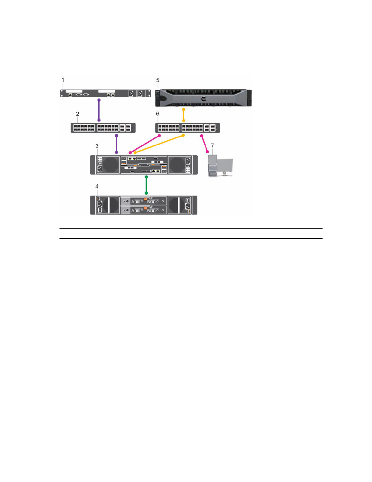
SCv2000/SCv2020 Storage System with Fibre Channel Front-End Connectivity
An SCv2000/SCv2020 storage system with Fibre Channel front-end connectivity may communicate with
the following components of a Storage Center system.
Figure 3. Storage System with Fibre Channel Front-End Connectivity
Item Description Speed Communication Type
1 Server with Fibre Channel host bus adapters
(HBAs)
8 Gbps or 16 Gbps Front End
2 Fibre Channel switch 8 Gbps or 16 Gbps Front End
3 SCv2000/SCv2020 storage system with FC
front-end connectivity
8 Gbps or 16 Gbps Front End
4 SC100/SC120 expansion enclosures 6 Gbps per channel Back End
5 Remote Storage Center connected via iSCSI
for replication
1 Gbps or 10 Gbps Front End
6 Ethernet switch 1 Gbps or 10 Gbps
(Management/
Replication)
Front End
7 Management network (computer connected
to the storage system through the Ethernet
switch)
Up to 1 Gbps System Administration
12
About the SCv2000/SCv2020 Storage System
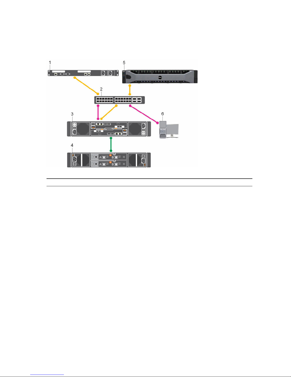
SCv2000/SCv2020 Storage System with iSCSI Front-End Connectivity
An SCv2000/SCv2020 storage system with iSCSI front-end connectivity may communicate with the
following components of a Storage Center system.
Figure 4. Storage System with iSCSI Front-End Connectivity
Item Description Speed Communication Type
1 Server with Ethernet (iSCSI) ports or iSCSI
host bus adapters (HBAs)
1 Gbps or 10 Gbps Front End
2 Ethernet switch 1 Gbps or 10 Gbps Front End
3 SCv2000/SCv2020 storage system with
iSCSI front-end connectivity
1 Gbps or 10 Gbps Front End
4 SC100/SC120 expansion enclosures 6 Gbps per channel Back End
5 Remote Storage Center connected via iSCSI
for replication
1 Gbps or 10 Gbps Front End
6 Management network (computer connected
to the storage system through the Ethernet
switch)
Up to 1 Gbps System Administration
About the SCv2000/SCv2020 Storage System
13
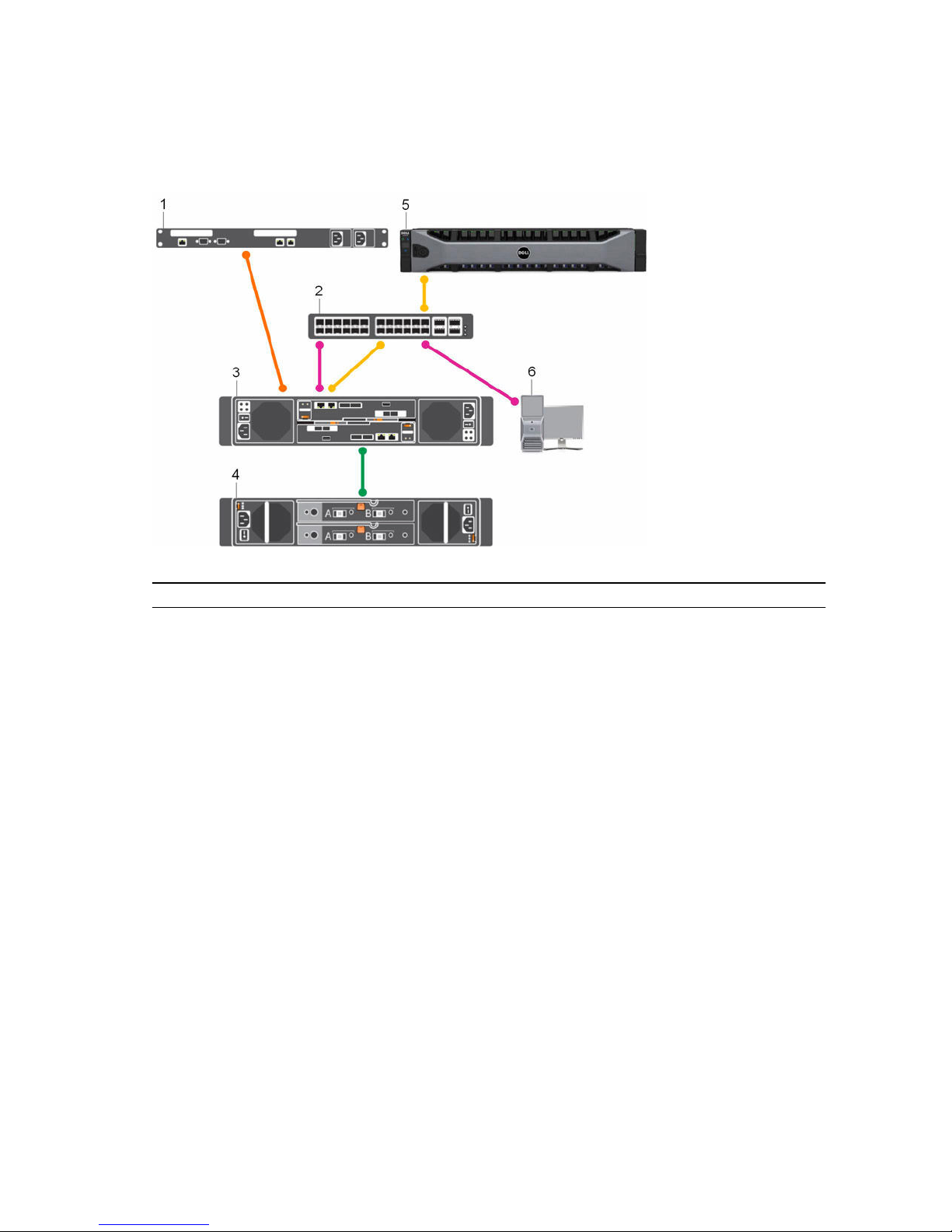
SCv2000/SCv2020 Storage System with SAS Front-End Connectivity
An SCv2000/SCv2020 storage system with SAS front-end connectivity may communicate with the
following components of a Storage Center system.
Figure 5. Storage System with SAS Front-End Connectivity
Item Description Speed Communication Type
1 Server with SAS host bus adapters (HBAs) 12 Gbps per channel Front End
2 Ethernet switch 1 Gbps or 10 Gbps
(Management/
Replication)
Front End
3 SCv2000/SCv2020 storage system with SAS
front-end connectivity
12 Gbps per channel Front End
4 SC100/SC120 expansion enclosures 6 Gbps per channel Back End
5 Remote Storage Center connected via iSCSI
for replication
1 Gbps or 10 Gbps Front End
6 Management network (computer connected
to the storage system through the Ethernet
switch)
Up to 1 Gbps System Administration
Back-End Connectivity
Back-end connectivity is strictly between the storage system and expansion enclosures, which hold the
physical drives that provide back-end expansion storage.
An SCv2000/SCv2020 storage system supports back-end connectivity to multiple expansion enclosures.
14
About the SCv2000/SCv2020 Storage System
System Administration
To perform system administration, the Storage Center communicates with computers using the Ethernet
management (MGMT) port.
The Ethernet management port is used for Storage Center configuration, administration, and
management.
NOTE: The baseboard management controller (BMC) does not have a separate physical port on the
SCv2000/SCv2020. The BMC is accessed through the same Ethernet management port that is used
for
Storage Center configuration, administration, and management.
SCv2000/SCv2020 Storage System Hardware
The SCv2000/SCv2020 storage system ships with Dell Enterprise drives, two redundant power supply/
cooling fan modules, and either one storage controller or two redundant storage controllers.
Each storage controller contains the front-end, back-end, and management communication ports of the
storage system.
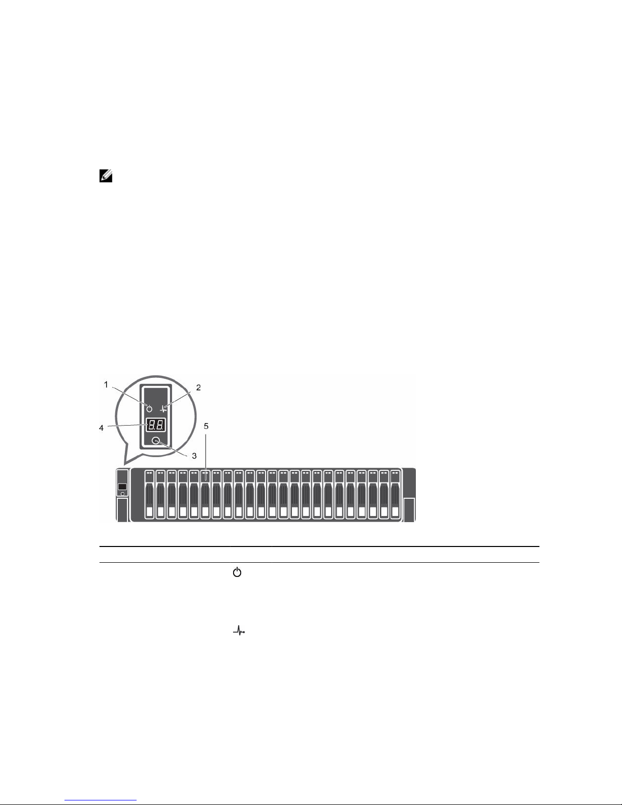
SCv2000/SCv2020 Storage System Front-Panel Features and Indicators
The front panel of the SCv2000/SCv2020 contains power and status indicators, a system identification
button, and a unit ID display.
In addition, the hard drives are installed and removed through the front of the storage system chassis.
Figure 6. SCv2000/SCv2020 Front-Panel View
Item Name Icon Description
1 Power indicator Lights when the storage system power is on.
• Off: No power
• On steady green: At least one power supply is providing
power to the storage system
2 Status indicator
Lights when at least one power supply is supplying power to
the storage system.
• Off: No power
• On steady blue: Power is on and firmware is running
• Blinking blue: Storage system is busy booting or updating
About the SCv2000/SCv2020 Storage System
15
Item Name Icon Description
• On steady amber: Hardware detected fault
• Blinking amber: Software detected fault
3 Identification
button
Lights when the storage system identification is enabled.
• Off: Normal status
• Blinking blue: Storage system identification enabled
4 Unit ID display — Displays the storage system identification number. The default
value for a new storage system is 01.
5 Hard drives — Can have up to 12 3.5-inch or 24 2.5-inch SAS hard drives.
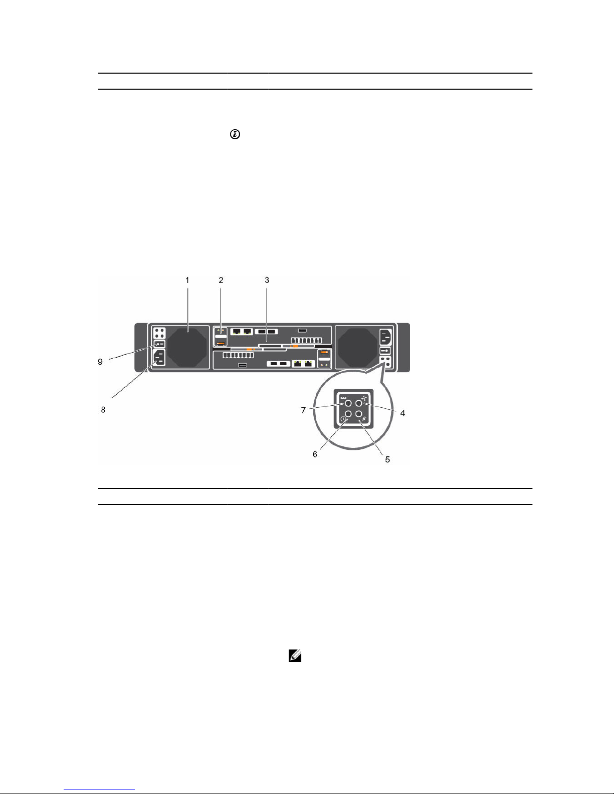
SCv2000/SCv2020 Back-Panel Features and Indicators
The back panel of the SCv2000/SCv2020 contains the storage controller indicators and power supply
indicators.
Figure 7. SCv2000/SCv2020 Back-Panel View
Item Name Icon Description
1 Power supply/
cooling fan module
(PSU) (2)
— Contains a 580 W power supply and fans that provide cooling
for the storage system.
2 Battery backup unit
(BBU) (2)
— Allows the storage controller to shut down smoothly when a
loss of AC power is detected.
3 Storage controller
(1 or 2)
— Each storage controller contains:
• Back-end ports: Two 6 Gbps SAS ports
• Front-end ports: Fibre Channel ports, iSCSI ports, or SAS
ports
• MGMT port: Embedded Ethernet/iSCSI port that is typically
used for system management
NOTE: The MGMT port can share iSCSI traffic if the
Flex Port license is installed.
16
About the SCv2000/SCv2020 Storage System
Item Name Icon Description
• REPL port: Embedded iSCSI port that is typically used for
replication to another Storage Center
4 Cooling fan fault
indicator (2)
• Off: Normal operation
• Steady amber: Fan fault or the storage system is having a
problem communicating with the PSU
• Blinking amber: PSU is in programming mode
5 AC power fault
indicator (2)
• Off: Normal operation
• Steady Amber: PSU has been removed or the storage
system is having a problem communicating with the PSU
• Blinking amber: PSU is in programming mode
6 AC power status
indicator (2)
• Off: AC power is off, the power is on but the PSU is not in
the storage system, or a hardware fault is possible
• Steady green: AC power is on
• Blinking green: AC power is on and the PSU is in standby
mode
7 DC power fault
indicator (2)
• Off: Normal operation
• Steady amber: PSU has been removed, a DC or other
hardware fault has occurred, or the storage system is
having a problem communicating with the PSU
• Blinking amber: PSU is in programming mode
8 Power socket (2) — Accepts a standard computer power cord.
9 Power switch (2) — Controls power for the storage system. Each PSU has one
switch.
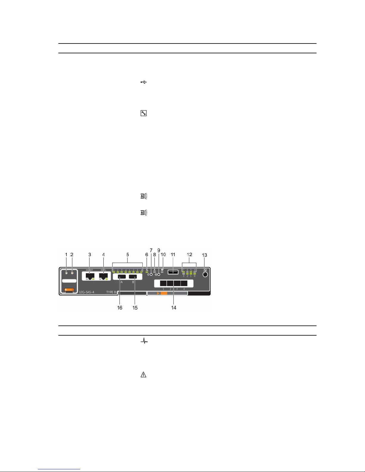
SCv2000/SCv2020 Storage Controller Features and Indicators
An SCv2000/SCv2020 storage system includes up to two storage controllers in two interface slots.
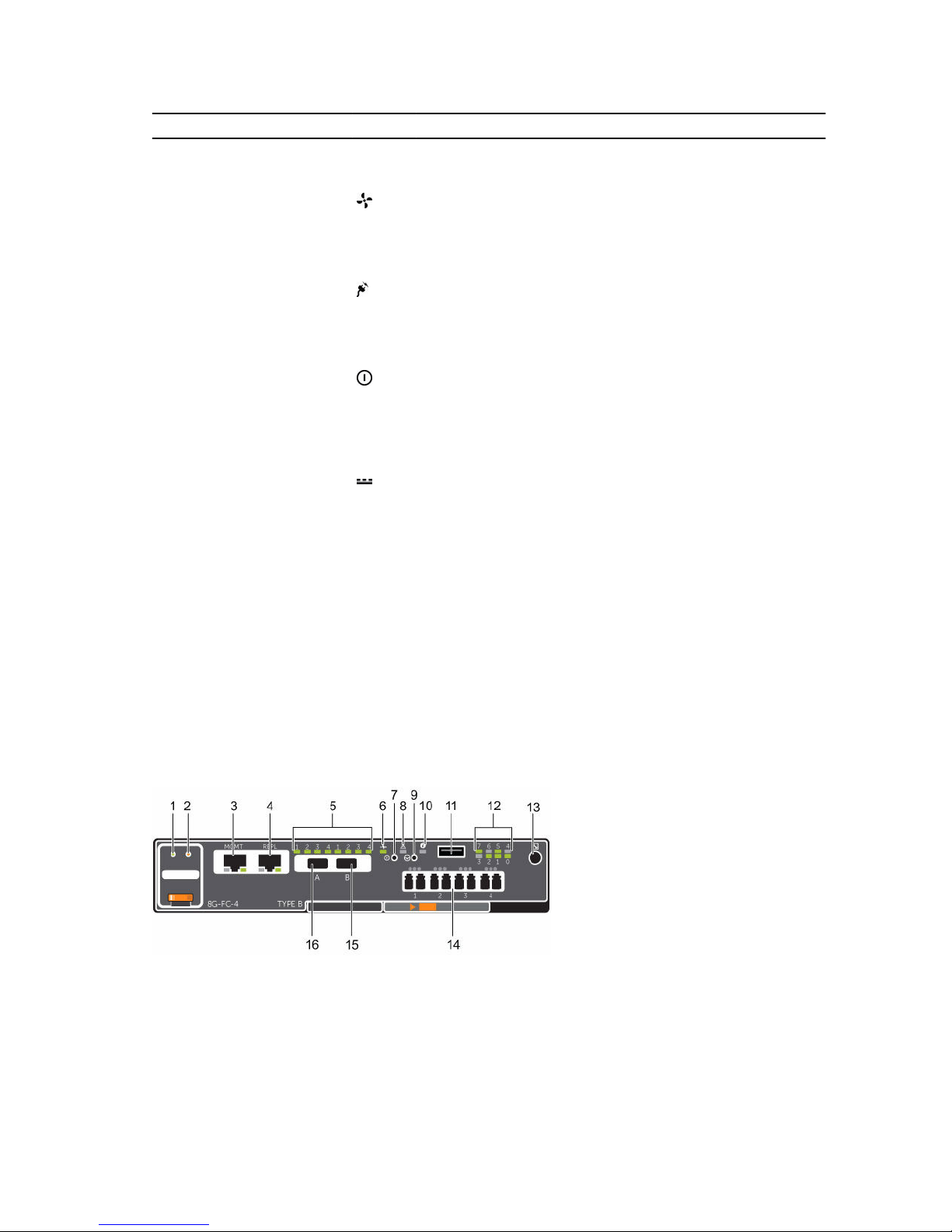
SCv2000/SCv2020 Storage System Storage Controller with Fibre Channel Front-End Ports
The following figures show the features and indicators on a storage controller with Fibre Channel frontend ports.
Figure 8. SCv2000/SCv2020 Storage System Storage Controller with Four 8 Gb Fibre Channel Front-End
Ports
About the SCv2000/SCv2020 Storage System
17
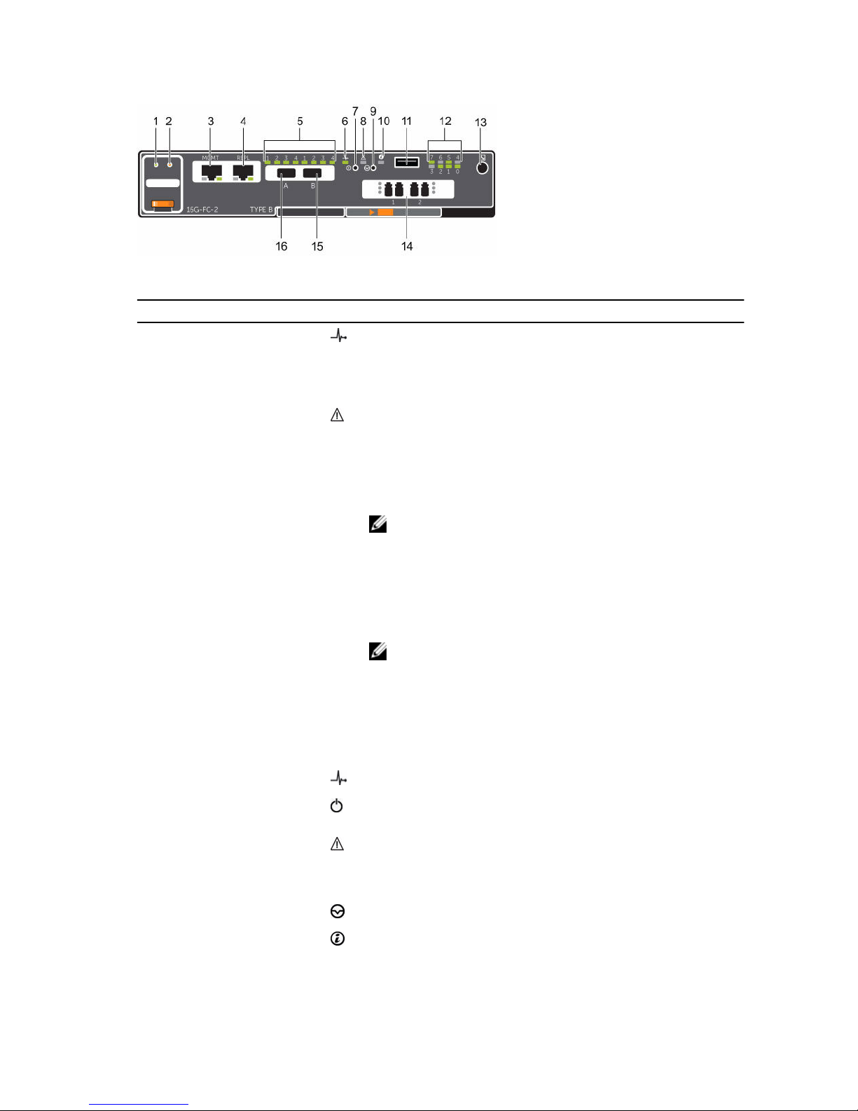
Figure 9. SCv2000/SCv2020 Storage System Storage Controller with Two 16 Gb Fibre Channel Front-End
Ports
Item Control/Feature Icon Description
1 Battery status indicator
• Blinking green (on 0.5 sec. / off 1.5 sec.): Battery heartbeat
• Fast blinking green (on 0.5 sec. / off 0.5 sec.): Battery is
charging
• Steady green: Battery is ready
2 Battery fault indicator
• Off: No faults
• Blinking amber: Correctable fault detected
• Steady amber: Uncorrectable fault detected; replace battery
3 MGMT port (Slot 3/Port 1)— Ethernet/iSCSI port that is typically used for storage system
management and access to the BMC
NOTE: To use the MGMT port as an iSCSI port for
replication to another Storage Center, a Flex Port license
and replication license are required. To use the MGMT port
as a front-end connection to host servers, a Flex Port
license is required.
4 REPL port (Slot 3/Port 2) — Ethernet/iSCSI port that is typically used for replication to
another Storage Center (requires a replication license)
NOTE: To use the RELP port as a front-end connection to
host servers, a Flex Port license is required.
5 SAS activity indicators — There are four SAS PHYs per SAS port.
• Off: SAS PHY is not connected
• Steady green: SAS PHY is connected, but not active
• Blinking green: SAS PHY is not connected nor active
6 Storage controller status On: Storage controller completed POST
7 Recessed power off
button
Not currently used
8 Storage controller fault
• Off: No faults
• Steady amber: Firmware has detected an error
• Blinking amber: Storage controller is performing POST
9 Recessed reset button Not currently used
10 Identification LED
• Off: Identification disabled
18
About the SCv2000/SCv2020 Storage System
Item Control/Feature Icon Description
• Blinking blue (for 15 sec.): Identification is enabled
• Blinking blue (continuously): Storage controller shut down
to the Advanced Configuration and Power Interface (ACPI)
S5 state
11 USB port One USB 3.0 connector
12 Diagnostic LEDs (8) —
• Green LEDs 0–3: Low byte hex POST code
• Green LEDs 4–7: High byte hex POST code
13 Serial port (3.5 mm mini
jack)
Not for customer use
14 Two options:
• Four Fibre Channel
ports (Slot 1/Port 1,
Slot 1/Port 2, Slot 1/
Port 3, and Slot 1/
Port 4) with three
LEDs per port
• Two Fibre Channel
ports (Slot 1/Port 1
and Slot 1/Port 2)
with three LEDs per
port
— Fibre Channel ports
• All off: No power
• All on: Booting up
• Blinking amber: 2 Gbps activity
• Blinking green: 4 Gbps activity
• Blinking yellow: 8 Gbps activity
• Blinking amber and yellow: Beacon
• All blinking (simultaneous): Firmware initialized
• All blinking (alternating): Firmware fault
15 Mini-SAS port B (Slot 2/
Port 2)
Back-end expansion port B
16 Mini-SAS port A (Slot 2/
Port 1)
Back-end expansion port A
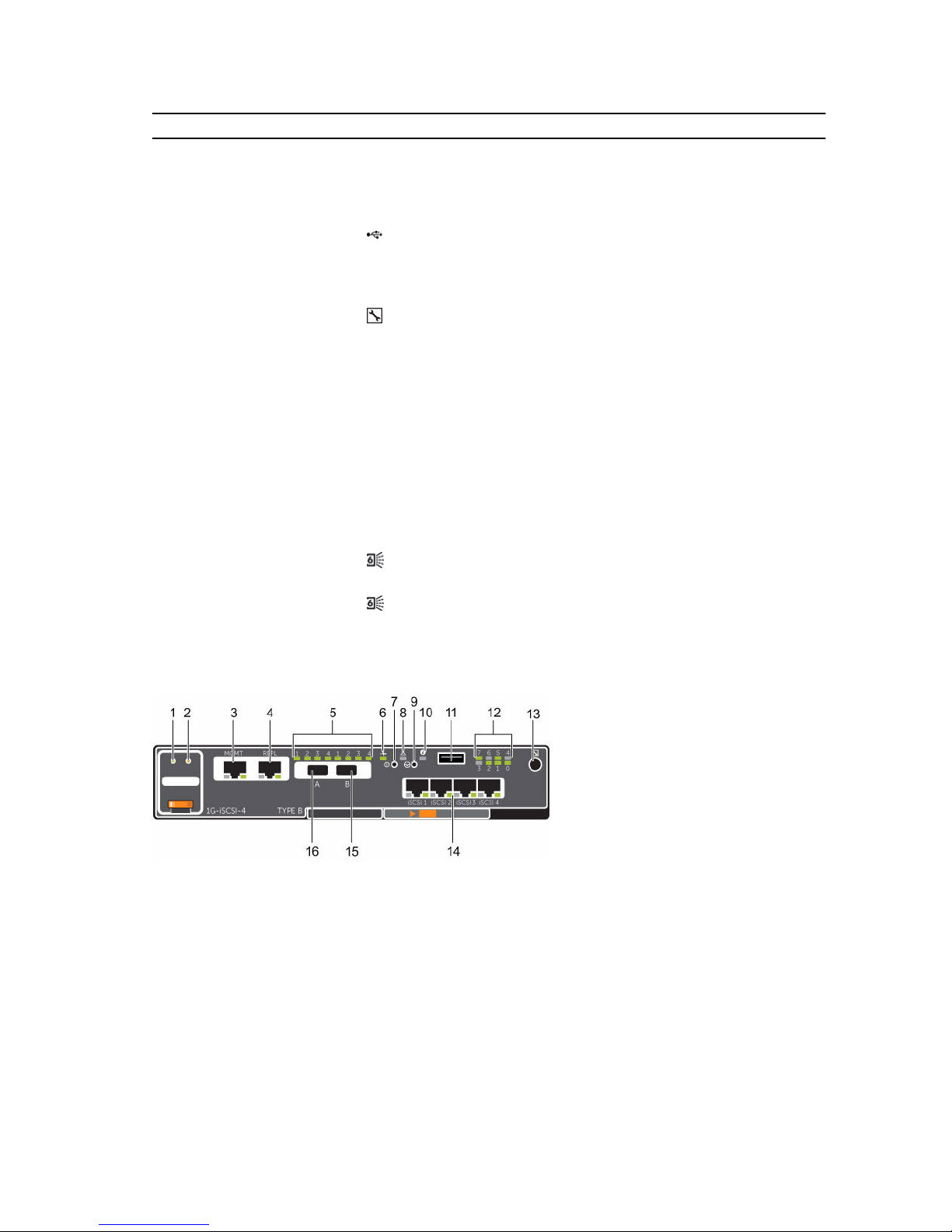
SCv2000/SCv2020 Storage System Storage Controller with iSCSI Front-End Ports
The following figures show the features and indicators on a storage controller with iSCSI front-end ports.
Figure 10. SCv2000/SCv2020 Storage System Storage Controller with Four 1 GbE iSCSI Front-End Ports
About the SCv2000/SCv2020 Storage System
19

Figure 11. SCv2000/SCv2020 Storage System Storage Controller with Two 10 GbE iSCSI Front-End Ports
Item Control/Feature Icon Description
1 Battery status indicator
• Blinking green (on 0.5 sec. / off 1.5 sec.): Battery heartbeat
• Fast blinking green (on 0.5 sec. / off 0.5 sec.): Battery is
charging
• Steady green: Battery is ready
2 Battery fault indicator
• Off: No faults
• Blinking amber: Correctable fault detected
• Steady amber: Uncorrectable fault detected; replace battery
3 MGMT port (Slot 3/Port 1)— Ethernet/iSCSI port that is typically used for storage system
management and access to the BMC
NOTE: To use the MGMT port as an iSCSI port for
replication to another Storage Center, a Flex Port license
and replication license are required. To use the MGMT port
as a front-end connection to host servers, a Flex Port
license is required.
4 REPL port (Slot 3/Port 2) — Ethernet/iSCSI port that is typically used for replication to
another Storage Center
NOTE: To use the RELP port as a front-end connection to
host servers, a Flex Port license is required.
5 SAS activity indicators — There are four SAS PHYs per SAS port.
• Off: SAS PHY is not connected
• Steady green: SAS PHY is connected, but not active
• Blinking green: SAS PHY is not connected nor active
6 Storage controller status On: Storage controller completed POST
7 Recessed power off
button
Not currently used
8 Storage controller fault
• Off: No faults
• Steady amber: Firmware has detected an error
• Blinking amber:Storage controller is performing POST
9 Recessed reset button Not currently used
10 Identification LED
• Off: Identification disabled
• Blinking blue (for 15 sec.): Identification is enabled
20
About the SCv2000/SCv2020 Storage System
Item Control/Feature Icon Description
• Blinking blue (continuously): Storage controller shut down
to the Advanced Configuration and Power Interface (ACPI)
S5 state
11 USB port One USB 3.0 connector
12 Diagnostic LEDs (8) —
• Green LEDs 0–3: Low byte hex POST code
• Green LEDs 4–7: High byte hex POST code
13 Serial port (3.5 mm mini
jack)
Not for customer use
14 Two options:
• Four iSCSI ports (Slot
1/Port 1, Slot 1/Port
2, Slot 1/Port 3, and
Slot 1/Port 4) with
two LEDs per port
• Two iSCSI ports (Slot
1/Port 1 and Slot 1/
Port 2) with two
LEDs per port
—
• Off: No power
• Steady Amber: Link
• Blinking Green: Activity
15 Mini-SAS port B (Slot 2/
Port 2)
Back-end expansion port B
16 Mini-SAS port A (Slot 2/
Port 1)
Back-end expansion port A
SCv2000/SCv2020 Storage System Storage Controller with SAS Front-End Ports
The following figure shows the features and indicators on a storage controller with SAS front-end ports.
Figure 12. SCv2000/SCv2020 Storage System Storage Controller with Four 12 Gb SAS Front-End Ports
Item Control/Feature Icon Description
1 Battery status indicator
• Blinking green (on 0.5 sec. / off 1.5 sec.): Battery heartbeat
• Fast blinking green (on 0.5 sec. / off 0.5 sec.): Battery is
charging
• Steady green: Battery is ready
2 Battery fault indicator
• Off: No faults
• Blinking amber: Correctable fault detected
• Steady amber: Uncorrectable fault detected; replace battery
About the SCv2000/SCv2020 Storage System
21

Item Control/Feature Icon Description
3 MGMT port (Slot 3/Port 1)— Ethernet/iSCSI port that is typically used for storage system
management and access to the BMC
NOTE: To use the MGMT port as an iSCSI port for
replication to another Storage Center, a Flex Port license
and replication license are required. To use the MGMT port
as a front-end connection to host servers, a Flex Port
license is required.
4 REPL port (Slot 3/Port 2) — Ethernet/iSCSI port that is typically used for replication to
another Storage Center
NOTE: To use the RELP port as a front-end connection to
host servers, a Flex Port license is required.
5 SAS activity indicators — There are four SAS PHYs per SAS port.
• Off: SAS PHY is not connected
• Steady green: SAS PHY is connected, but not active
• Blinking green: SAS PHY is not connected nor active
6 Storage controller
module status
On: Storage controller completed POST
7 Recessed power off
button
Not currently used
8 Storage controller
module fault
• Off: No faults
• Steady amber: Firmware has detected an error
• Blinking amber: Storage controller is performing POST
9 Recessed reset button Not currently used
10 Identification LED
• Off: Identification disabled
• Blinking blue (for 15 sec.): Identification is enabled
• Blinking blue (continuously): Storage controller shut down
to the Advanced Configuration and Power Interface (ACPI)
S5 state
11 USB port One USB 3.0 connector
12 Diagnostic LEDs (8) —
• Green LEDs 0–3: Low byte hex POST code
• Green LEDs 4–7: High byte hex POST code
13 Serial port (3.5 mm mini
jack)
Not for customer use
14 Four Mini-SAS High
Density (HD) ports (Slot
1/Port 1, Slot 1/Port 2,
Slot 1/Port 3, and Slot 1/
Port 4)
— Front-end connectivity ports
NOTE: The mini-SAS HD ports are for front-end
connectivity only and cannot be used for back-end
expansion.
15 Mini-SAS port B (Slot 2/
Port 2)
Back-end expansion port B
16 Mini-SAS port A (Slot 2/
Port 1)
Back-end expansion port A
22
About the SCv2000/SCv2020 Storage System
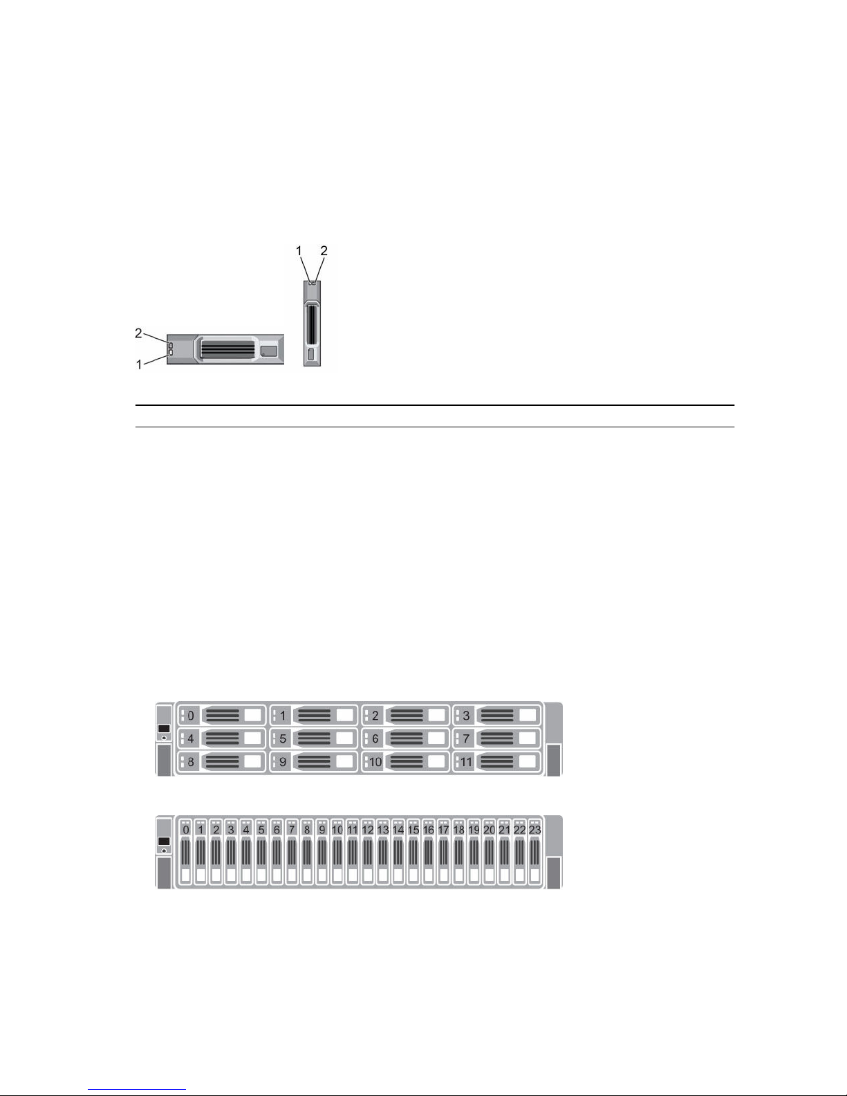
SCv2000/SCv2020 Drives
Dell Enterprise hard disk drives (HDDs) and Enterprise solid-state drives (eSSDs) are the only drives that
can be installed in an SCv2000/SCv2020 storage system. If a non-Dell Enterprise drive is installed,
Storage Center prevents the drive from being managed.
The drives in an SCv2000 storage system are installed horizontally. The drives in an SCv2020 storage
system are installed vertically. The indicators on the drives provide status and activity information.
Figure 13. SCv2000/SCv2020 Drive Indicators
Item Control/Feature Indicator Code
1 Drive activity
indicator
• Blinking green: Drive activity
• Steady green: Drive is detected and has no faults
2 Drive status
indicator
• Off: Normal operation
• Blinking amber (on 1 sec. / off 1 sec.): Drive identification is enabled
• Blinking amber (on 2 sec. / off 1 sec.): Hardware/firmware fault
• Steady amber: Drive is safe to remove
SCv2000/SCv2020 Storage System Drive Numbering
In an SCv2000/SCv2020 storage system, the drives are numbered from left to right.
Dell Storage Client identifies drives as XX-YY, where XX is the number of the unit ID of the storage
system, and YY is the drive position inside the storage system.
• An SCv2000 holds up to 12 drives, which are numbered from left to right in rows starting from 0 at
the top-left drive.
Figure 14. SCv2000 Drive Numbering
• An SCv2020 holds up to 24 drives, which are numbered from eft to right starting from 0.
Figure 15. SCv2020 Drive Numbering
About the SCv2000/SCv2020 Storage System
23
SC100/SC120 Expansion Enclosure Overview
The SC100 is a 2U expansion enclosure that supports up to 12 3.5‐inch hard drives installed in a four‐
column, three-row configuration. The SC120 is a 2U expansion enclosure that supports up to 24 2.5‐inch
hard drives installed vertically side by side.
An SC100/SC120 expansion enclosure ships with two redundant power supply/cooling fan modules and
two redundant enclosure management modules (EMMs).
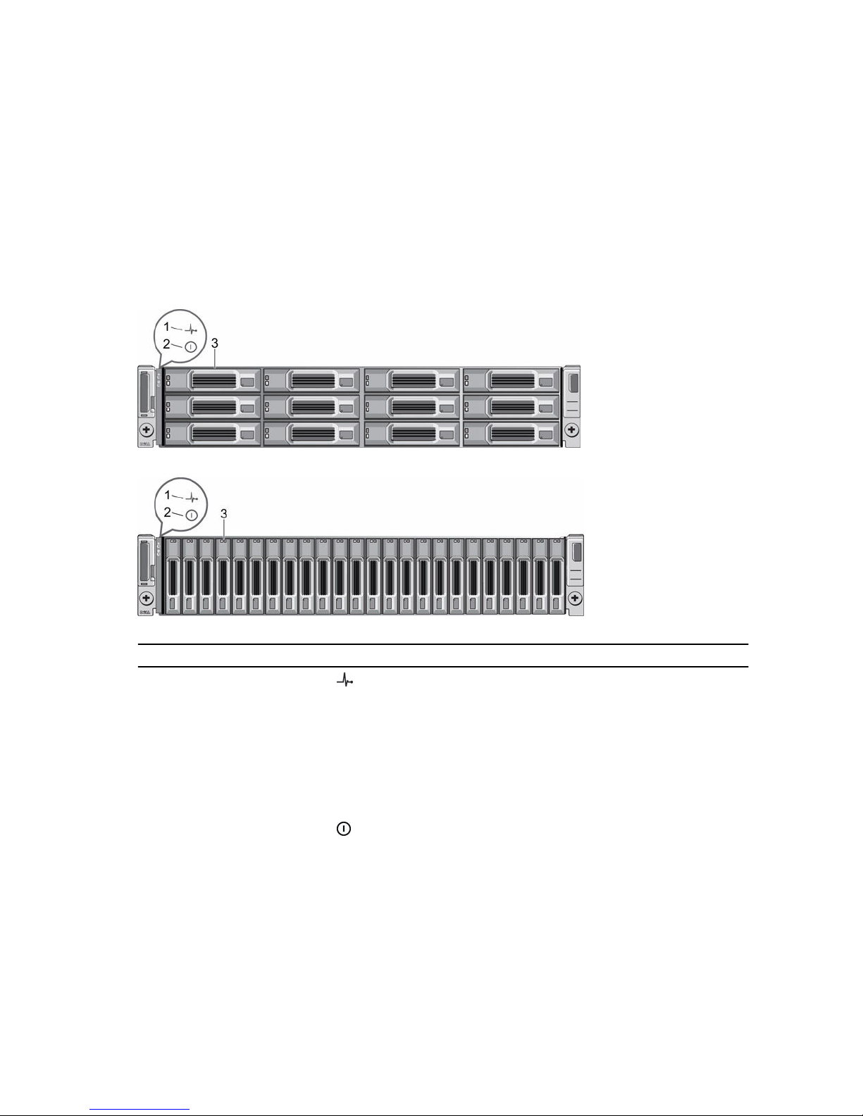
SC100/SC120 Expansion Enclosure Front-Panel Features and Indicators
The SC100/SC120 front panel shows the expansion enclosure status and power supply status.
Figure 16. SC100 Front-Panel Features and Indicators
Figure 17. SC120 Front-Panel Features and Indicators
Item Name Icon Description
1 Expansion enclosure
status indicator
Lights when the expansion enclosure power is on.
• Off: No power
• On steady blue: Normal operation
• Blinking blue: Storage Center is identifying the
enclosure
• On steady amber: Expansion enclosure is turning on or
was reset
• Blinking amber: Expansion enclosure is in the fault state
2 Power supply status
indicator
Lights when at least one power supply is supplying power
to the expansion enclosure.
• Off: Both power supplies are off
• On steady green: At least one power supply is providing
power to the expansion enclosure
3 Hard drives — Dell Enterprise Plus Drives
• SC100: Up to 12 3.5-inch hard drives
24
About the SCv2000/SCv2020 Storage System
Item Name Icon Description
• SC120: Up to 24 2.5-inch hard drives
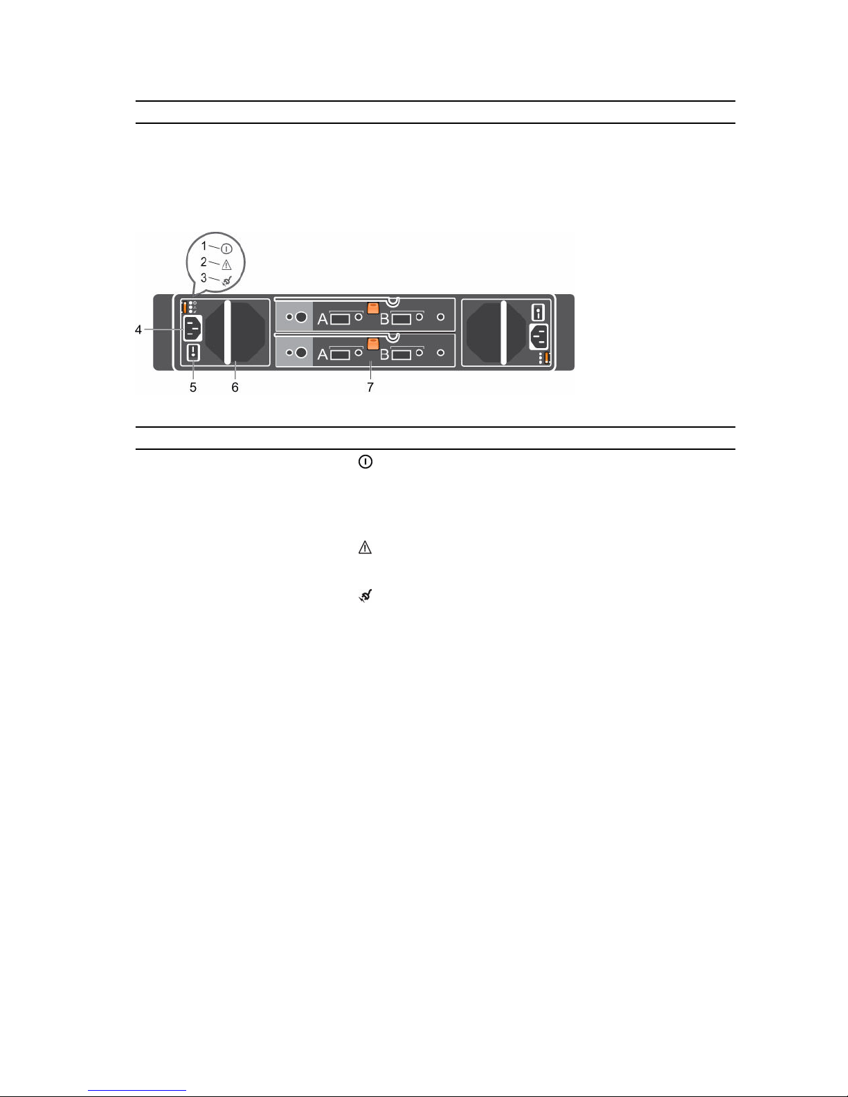
SC100/SC120 Expansion Enclosure Back-Panel Features and Indicators
The SC100/SC120 back panel provides controls to power up and reset the expansion enclosure,
indicators to show the expansion enclosure status, and connections for back-end cabling.
Figure 18.
SC100/SC120 Back Panel Features and Indicators
Item Name Icon Description
1 DC power indicator
• Green: Normal operation. The power supply
module is supplying DC power to the expansion
enclosure
• Off: Power switch is off, the power supply is not
connected to AC power, or has a fault condition
2 Power supply/cooling fan
indicator
• Amber: Power supply/cooling fan fault is detected
• Off: Normal operation
3 AC power indicator
• Green: Power supply module is connected to a
source of AC power, whether or not the power
switch is on
• Off: Power supply module is disconnected from a
source of AC power
4 Power socket (2) — Accepts a standard computer power cord.
5 Power switch (2) — Controls power for the expansion enclosure. Each
power supply/cooling fan module has one switch.
6 Power supply/cooling fan
module (2)
— Contains a 700 W power supply and fans that provide
cooling for the expansion enclosure.
7 Enclosure management
module (2)
— EMMs provide the data path and management
functions for the expansion enclosure.
About the SCv2000/SCv2020 Storage System
25
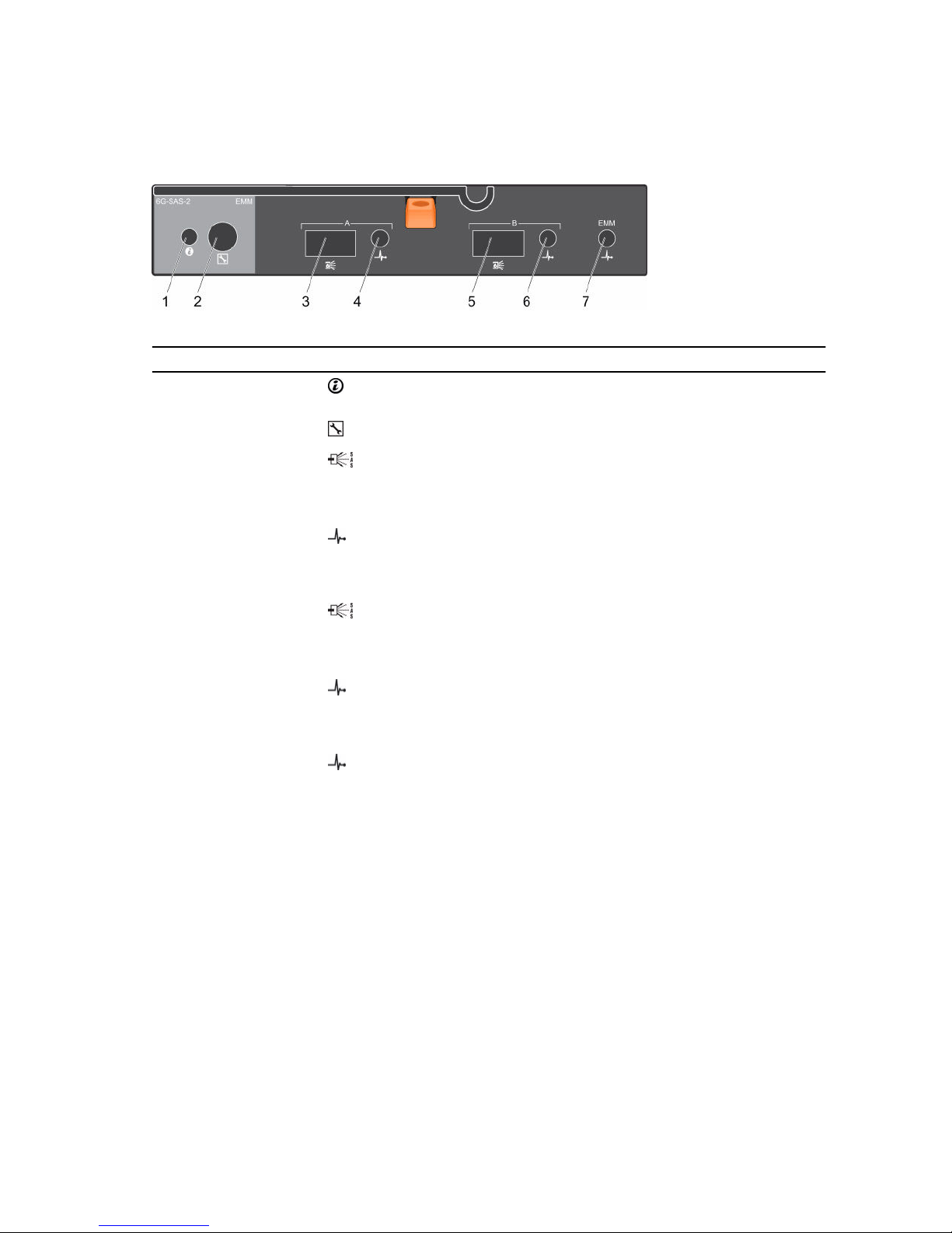
SC100/SC120 Expansion Enclosure EMM Features and Indicators
The SC100/SC120 includes two enclosure management modules (EMMs) in two interface slots.
Figure 19. SC100/SC120 EMM Features and Indicators
Item Name Icon Description
1 System status
indicator
Not used on SC100/SC120 expansion enclosures.
2 Serial port Not for customer use.
3 SAS port A (in) Connects to a storage controller or to other SC100/SC120
expansion enclosures. SAS ports A and B can be used for either
input or output. However, for cabling consistency, use port A as
an input port.
4 Port A link
status
• Green: All the links to the port are connected
• Amber: One or more links are not connected
• Off: Expansion enclosure is not connected
5 SAS port B
(out)
Connects to a storage controller or to other SC100/SC120
expansion enclosures. SAS ports A and B can be used for either
input or output. However, for cabling consistency, use port B as
an output port.
6 Port B link
status
• Green: All the links to the port are connected
• Amber: One or more links are not connected
• Off: Expansion enclosure is not connected
7 EMM status
indicator
• On steady green: Normal operation
• Amber: Expansion enclosure did not boot or is not properly
configured
• Blinking green: Automatic update in progress
• Blinking amber (two times per sequence): Expansion
enclosure is unable to communicate with other expansion
enclosures
• Blinking amber (four times per sequence): Firmware update
failed
• Blinking amber (five times per sequence): Firmware versions
are different between the two EMMs
26
About the SCv2000/SCv2020 Storage System
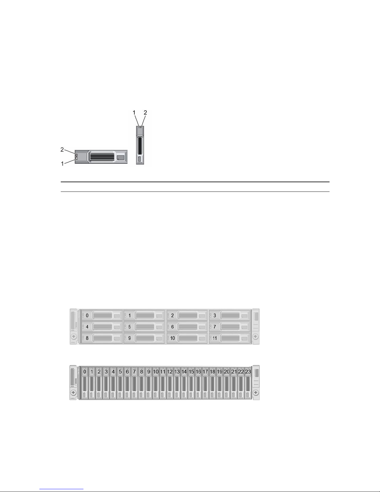
SC100/SC120 Expansion Enclosure Drives
Dell Enterprise hard disk drives (HDDs) and Enterprise solid-state drives (eSSDs) are the only drives that
can be installed in SC100/SC120 expansion enclosures. If a non-Dell Enterprise drive is installed, the
Storage Center prevents the drive from being managed.
The drives in an SC100 expansion enclosure are installed horizontally. The drives in an SC120 expansion
enclosure are installed vertically. The indicators on the drives provide status and activity information.
Figure 20. SC100/SC120 Drive Indicators
Item Name Indicator Code
1 Drive activity
indicator
• Blinking green: Drive activity
• Steady green: Drive is detected and there are no faults
2 Drive status
indicator
• Steady green: Normal operation
• Blinking green (on 1 sec. / off 1 sec.): Drive identification is enabled
• Steady amber: Drive is safe to remove
• Off: No power to the drive
SC100/SC120 Expansion Enclosure Drive Numbering
In an SC100/SC120 expansion enclosure, the drives are numbered from left to right starting from 0.
Dell Storage Client identifies drives as XX-YY, where XX is the unit ID of the expansion enclosure that
contains the drive, and YY is the drive position inside the expansion enclosure.
• An SC100 holds up to 12 drives, which are numbered in rows starting from 0 at the top-left drive.
Figure 21. SC100 Drive Numbering
• An SC120 holds up to 24 drives, which are numbered left to right starting from 0.
Figure 22. SC120 Drive Numbering
About the SCv2000/SCv2020 Storage System
27
2
Install the Storage Center Hardware
This section describes how to unpack the Storage Center equipment, prepare for the installation, and
mount the equipment in a rack.
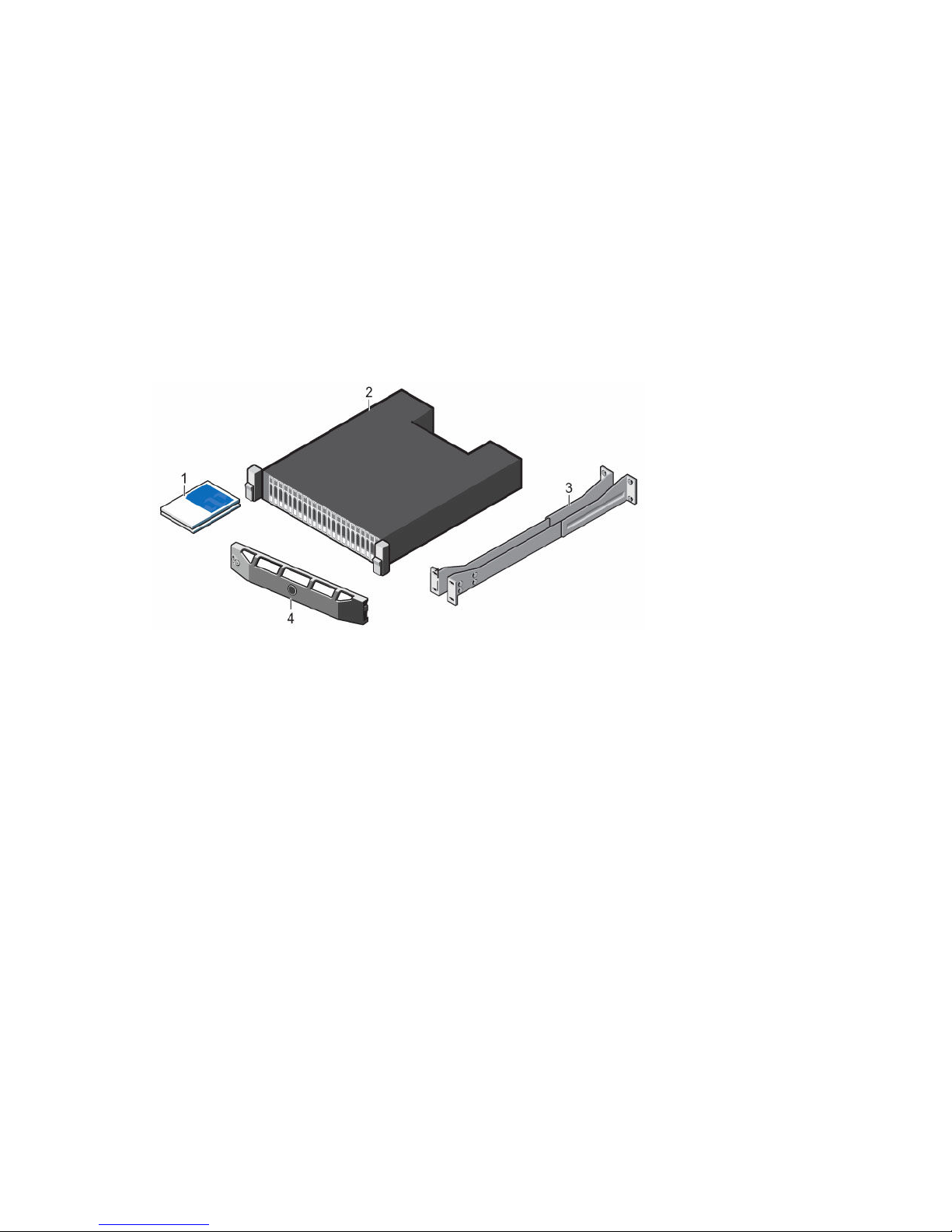
Unpack and Inventory the Storage Center Equipment
Unpack the storage system and identify the items in your shipment.
Figure 23. SCv2000/SCv2020 Storage System Components
1. Documentation 2. Storage system
3. Rack rails 4. Front bezel
Prepare the Installation Environment
Make sure that the environment is ready for Storage Center installation.
• Rack Space: The rack must have enough space to accommodate the storage system chassis,
expansion enclosures, and switches.
• Power: Power must be available in the rack, and the power delivery system must meet the
requirements of the Storage Center.
• Connectivity: The rack must be wired for connectivity to the management network and any networks
that carry front-end IO from the Storage Center to servers.
Safety Precautions
Always follow these safety precautions to avoid injury and damage to Storage Center equipment.
If equipment described in this section is used in a manner not specified by Dell, the protection provided
by the equipment could be impaired. For your safety and protection, observe the rules described in the
following sections.
28
Install the Storage Center Hardware

NOTE: See the safety and regulatory information that shipped with each Storage Center
component. Warranty information is included within this document or as a separate document.
Installation Safety Precautions
Follow these safety precautions:
• Dell recommends that only individuals with rack-mounting experience install an SCv2000/SCv2020
storage system in a rack.
• Make sure the storage system is always fully grounded to prevent damage from electrostatic
discharge.
• When handling the storage system hardware, use an electrostatic wrist guard (not included) or a
similar form of protection.
The storage system chassis must be mounted in a rack. The following safety requirements must be
considered when the chassis is being mounted:
• The rack construction must be capable of supporting the total weight of the installed chassis. The
design should incorporate stabilizing features suitable to prevent the rack from tipping or being
pushed over during installation or in normal use.
• To avoid danger of the rack toppling over, slide only one chassis out of the rack at a time.
• The rack design should take into consideration the maximum operating ambient temperature for the
unit, which is 57°C.
Electrical Safety Precautions
Always follow electrical safety precautions to avoid injury and damage to Storage Center equipment.
WARNING: Disconnect power from the storage system when removing or installing components
that are not hot-swappable. When disconnecting power, first power down the storage system
using the Dell Storage Client and then unplug the power cords from all the power supplies in the
storage system.
• Provide a suitable power source with electrical overload protection. All Storage Center components
must be grounded before applying power. Make sure that there is a safe electrical earth connection to
power supply cords. Check the grounding before applying power.
• The plugs on the power supply cords are used as the main disconnect device. Make sure that the
socket outlets are located near the equipment and are easily accessible.
• Know the locations of the equipment power switches and the room's emergency power-off switch,
disconnection switch, or electrical outlet.
• Do not work alone when working with high-voltage components.
• Use rubber mats specifically designed as electrical insulators.
• Do not remove covers from the power supply unit. Disconnect the power connection before
removing a power supply from the storage system.
• Do not remove a faulty power supply unless you have a replacement model of the correct type ready
for insertion. A faulty power supply must be replaced with a fully operational module power supply
within 24 hours.
• Unplug the storage system chassis before you move it or if you think it has become damaged in any
way. When powered by multiple AC sources, disconnect all supply power for complete isolation.
Install the Storage Center Hardware
29

Electrostatic Discharge Precautions
Always follow electrostatic discharge (ESD) precautions to avoid injury and damage to Storage Center
equipment.
Electrostatic discharge (ESD) is generated by two objects with different electrical charges coming into
contact with each other. The resulting electrical discharge can damage electronic components and
printed circuit boards. Follow these guidelines to protect your equipment from ESD:
• Dell recommends that you always use a static mat and static strap while working on components in
the interior of the storage system chassis.
• Observe all conventional ESD precautions when handling plug-in modules and components.
• Use a suitable ESD wrist or ankle strap.
• Avoid contact with backplane components and module connectors.
• Keep all components and printed circuit boards (PCBs) in their antistatic bags until ready for use.
General Safety Precautions
Always follow general safety precautions to avoid injury and damage to Storage Center equipment.
• Keep the area around the storage system chassis clean and free of clutter.
• Place any system components that have been removed away from the storage system chassis or on a
table so that they are not in the way of foot traffic.
• While working on the storage system chassis, do not wear loose clothing such as neckties and
unbuttoned shirt sleeves, which can come into contact with electrical circuits or be pulled into a
cooling fan.
• Remove any jewelry or metal objects from your body because they are excellent metal conductors
that can create short circuits and harm you if they come into contact with printed circuit boards or
areas where power is present.
• Do not lift a storage system chassis by the handles of the power supply units (PSUs). They are not
designed to hold the weight of the entire chassis, and the chassis cover may become bent.
• Before moving a storage system chassis, remove the PSUs to minimize weight.
• Do not remove drives until you are ready to replace them.
NOTE: To ensure proper storage system cooling, hard drive blanks must be installed in any hard
drive slot that is not occupied.
Install the Storage System in a Rack
Install the storage system and other Storage Center system components in a rack.
About this task
Mount the storage system and expansion enclosures in a manner that allows for expansion in the rack
and prevents the rack from becoming top‐heavy.
Steps
1. Secure the rails that are attached to both sides of the storage system chassis.
a. Lift the locking tab on the rail.
b. Push the rail toward the back of the chassis until it locks in place.
2. Determine where to mount the storage system and mark the location at the front and back of the
rack.
30
Install the Storage Center Hardware
 Loading...