

Dell Storage Center SC200, Storage Center SC220 Service Manual

Storage Center™
SC200 and SC220 Enclosures
Service Guide
Storage Center SC200 and SC220 Enclosures Service Guide
Document Number: 690-030-001
Revision Date Description
A September 2012 Initial release.
B December 2012 Updated the document template.
Notes, Cautions, and Warnings
Note: Indicates important information that helps you complete a procedure.
Caution: Indicates either potential damage to hardware or loss of data and tells you how to avoid
the problem.
Warning: Indicates that failure to follow directions could result in property damage, personal injury,
or death.
Copyright Notice and Trademarks
© 2012 Dell Inc.
Trademarks used in this text: Dell™, the Dell logo, and Compellent™ are trademarks of Dell Inc.
Contacting Dell Technical Support Services
For technical support, go to support.dell.com/compellent/.

Contents
1 About the SC200/220 . . . . . . . . . . . . . . . . . . . . . . . . . . . . . . . . . . . 1
SC200 and SC220 Overview . . . . . . . . . . . . . . . . . . . . . . . . . . . . . . . . . . . . . . . . . . . . . . . . . . . . . 1
SC200 and SC220 Hardware . . . . . . . . . . . . . . . . . . . . . . . . . . . . . . . . . . . . . . . . . . . . . . . . . . 1
SC200 and SC220 Monitoring and Diagnostics . . . . . . . . . . . . . . . . . . . . . . . . . . . . . . . . . . . . 1
Front-Panel Features and Indicators . . . . . . . . . . . . . . . . . . . . . . . . . . . . . . . . . . . . . . . . . . . . . . . 2
Back-Panel Features and Indicators . . . . . . . . . . . . . . . . . . . . . . . . . . . . . . . . . . . . . . . . . . . . . . . . 3
Enclosure Management Module Features and Indicators . . . . . . . . . . . . . . . . . . . . . . . . . . . . . . . 4
Hard Drive Indicators . . . . . . . . . . . . . . . . . . . . . . . . . . . . . . . . . . . . . . . . . . . . . . . . . . . . . . . . . . . 5
2 Replacing SC200/220 Components . . . . . . . . . . . . . . . . . . . . . . . 7
Safety Precautions . . . . . . . . . . . . . . . . . . . . . . . . . . . . . . . . . . . . . . . . . . . . . . . . . . . . . . . . . . . . . 7
Electrical Safety Precautions . . . . . . . . . . . . . . . . . . . . . . . . . . . . . . . . . . . . . . . . . . . . . . . . . . . 7
General Safety Precautions . . . . . . . . . . . . . . . . . . . . . . . . . . . . . . . . . . . . . . . . . . . . . . . . . . . . 8
Electrostatic Discharge Precautions . . . . . . . . . . . . . . . . . . . . . . . . . . . . . . . . . . . . . . . . . . . . . 8
Pre-Replacement Procedures . . . . . . . . . . . . . . . . . . . . . . . . . . . . . . . . . . . . . . . . . . . . . . . . . . . . 8
Phone Home . . . . . . . . . . . . . . . . . . . . . . . . . . . . . . . . . . . . . . . . . . . . . . . . . . . . . . . . . . . . . . . 9
Contact Dell Technical Support Services . . . . . . . . . . . . . . . . . . . . . . . . . . . . . . . . . . . . . . . . . 9
Shut Down the Controller(s) and Enclosure(s) . . . . . . . . . . . . . . . . . . . . . . . . . . . . . . . . . . . . . 9
Replacing the Front Bezel . . . . . . . . . . . . . . . . . . . . . . . . . . . . . . . . . . . . . . . . . . . . . . . . . . . . . . . 9
Replacing Power Supply/Cooling Fan Modules . . . . . . . . . . . . . . . . . . . . . . . . . . . . . . . . . . . . . . . 10
Identifying the Failed Power Supply/Cooling Fan Module . . . . . . . . . . . . . . . . . . . . . . . . . . . . . 10
Replacing a Power Supply/Cooling Fan Module . . . . . . . . . . . . . . . . . . . . . . . . . . . . . . . . . . . . 11
Replacing Hard Drives . . . . . . . . . . . . . . . . . . . . . . . . . . . . . . . . . . . . . . . . . . . . . . . . . . . . . . . . . . 13
Hard Drive Numbering . . . . . . . . . . . . . . . . . . . . . . . . . . . . . . . . . . . . . . . . . . . . . . . . . . . . . . . . 13
Identifying the Failed Hard Drive . . . . . . . . . . . . . . . . . . . . . . . . . . . . . . . . . . . . . . . . . . . . . . . .13
Replacing Hard Drives . . . . . . . . . . . . . . . . . . . . . . . . . . . . . . . . . . . . . . . . . . . . . . . . . . . . . . . . 14
Replacing an Enclosure Management Module . . . . . . . . . . . . . . . . . . . . . . . . . . . . . . . . . . . . . . . . 17
Identifying the Failed Enclosure Management Module . . . . . . . . . . . . . . . . . . . . . . . . . . . . . . . 17
Replacing an Enclosure Management Module . . . . . . . . . . . . . . . . . . . . . . . . . . . . . . . . . . . . . 18
Replacing the Control Panel . . . . . . . . . . . . . . . . . . . . . . . . . . . . . . . . . . . . . . . . . . . . . . . . . . . . . . 19
Replacing the Backplane . . . . . . . . . . . . . . . . . . . . . . . . . . . . . . . . . . . . . . . . . . . . . . . . . . . . . . . . 20
Replacing Rack Rails . . . . . . . . . . . . . . . . . . . . . . . . . . . . . . . . . . . . . . . . . . . . . . . . . . . . . . . . . . . 23
Post-Replacement Procedures . . . . . . . . . . . . . . . . . . . . . . . . . . . . . . . . . . . . . . . . . . . . . . . . . . . . 24
Start Up the Controller(s) and Enclosure(s) . . . . . . . . . . . . . . . . . . . . . . . . . . . . . . . . . . . . . . . 24
Phone Home . . . . . . . . . . . . . . . . . . . . . . . . . . . . . . . . . . . . . . . . . . . . . . . . . . . . . . . . . . . . . . . 24
Contact Dell Technical Support Services . . . . . . . . . . . . . . . . . . . . . . . . . . . . . . . . . . . . . . . . . 24
3 Troubleshooting SC200/220 Components . . . . . . . . . . . . . . . . . . 25
Troubleshooting Power Supply/Cooling Fan Modules . . . . . . . . . . . . . . . . . . . . . . . . . . . . . . . . . . 25
Dell Compellent iii

Contents
Troubleshooting Hard Drives . . . . . . . . . . . . . . . . . . . . . . . . . . . . . . . . . . . . . . . . . . . . . . . . . . . . . 26
Troubleshooting Enclosure Management Modules . . . . . . . . . . . . . . . . . . . . . . . . . . . . . . . . . . . . 26
Troubleshooting the Control Panel . . . . . . . . . . . . . . . . . . . . . . . . . . . . . . . . . . . . . . . . . . . . . . . . . 26
4 SC200/SC220 Specifications . . . . . . . . . . . . . . . . . . . . . . . . . . . . . 27
Technical Specifications . . . . . . . . . . . . . . . . . . . . . . . . . . . . . . . . . . . . . . . . . . . . . . . . . . . . . . . . . 27
iv Storage Center SC200 and S C2 20 En closures Service Gu ide

1 About the SC200/220
The SC200 and SC220 Enclosures Service Guide provides information about enclosure
service and maintenance. The information provided in this Service Guide is intended to be
used only by Dell-certified service engineers.
Contents
SC200 and SC220 Overview . . . . . . . . . . . . . . . . . . . . . . . . . . . . . . . . . . . . . . . . . . . . . 1
Front-Panel Features and Indicators . . . . . . . . . . . . . . . . . . . . . . . . . . . . . . . . . . . . . . . 2
Back-Panel Features and Indicators . . . . . . . . . . . . . . . . . . . . . . . . . . . . . . . . . . . . . . . 3
Enclosure Management Module Features and Indicators . . . . . . . . . . . . . . . . . . . . . . . 4
Hard Drive Indicators . . . . . . . . . . . . . . . . . . . . . . . . . . . . . . . . . . . . . . . . . . . . . . . . . . . 5
SC200 and SC220 Overview
A Storage Center enclosure holds the physical disks that provide storage. The interface
between the controller IO cards and the enclosure is refe rr ed to as back-end con nectivity.
SC200 and SC220 Hardware
The Storage Center SC200 and SC220 are 2U size SAS enclosures. The SC200 en closure
supports up to 12 3.5-inch hard drives installed in a four-column, three- row configuration.
The SC220 enclosure supports up to 24 2.5-inch hard drives installed vertically side-byside. The SC200 and SC220 enclosures ship with two power supply/cooling fan modules
and two redundant enclosure management modules (E MMs).
SC200 and SC220 Monitoring and Diagnostics
The Storage Center OS generates alert messages for temperature, IO module, fan, disk,
and power conditions for Storage Center components. Use the Storage Center System
Manager to view these alerts.
The SC200 and SC220 enclosures also have LED indicators to notify you of a possible
problem with the enclosure.
Note: Dell OpenManage Server Administrator is not available for SC200 and
SC220 enclosures.
Dell Compellent 1
Chapter 1 About the SC200/220
2
1
3
2
1
3
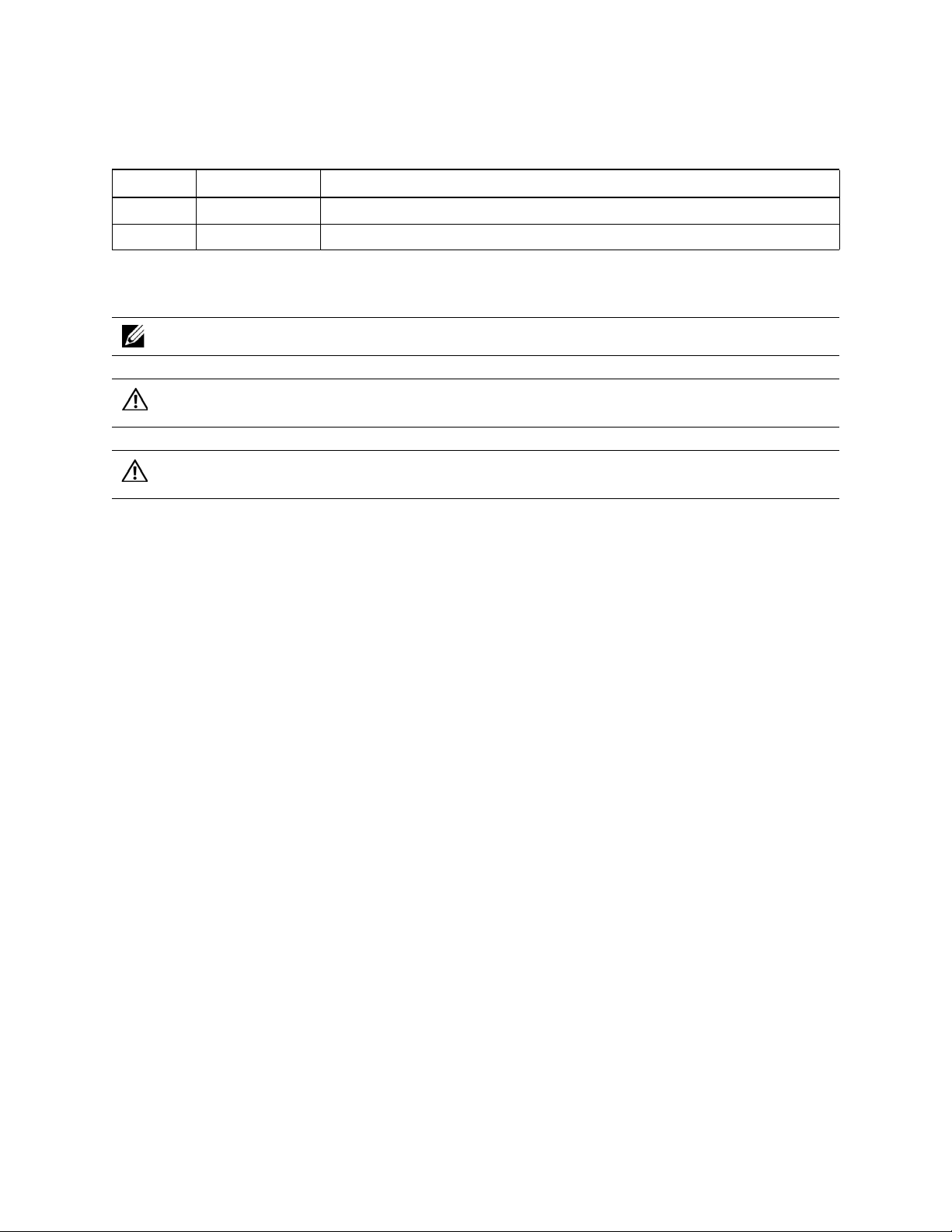
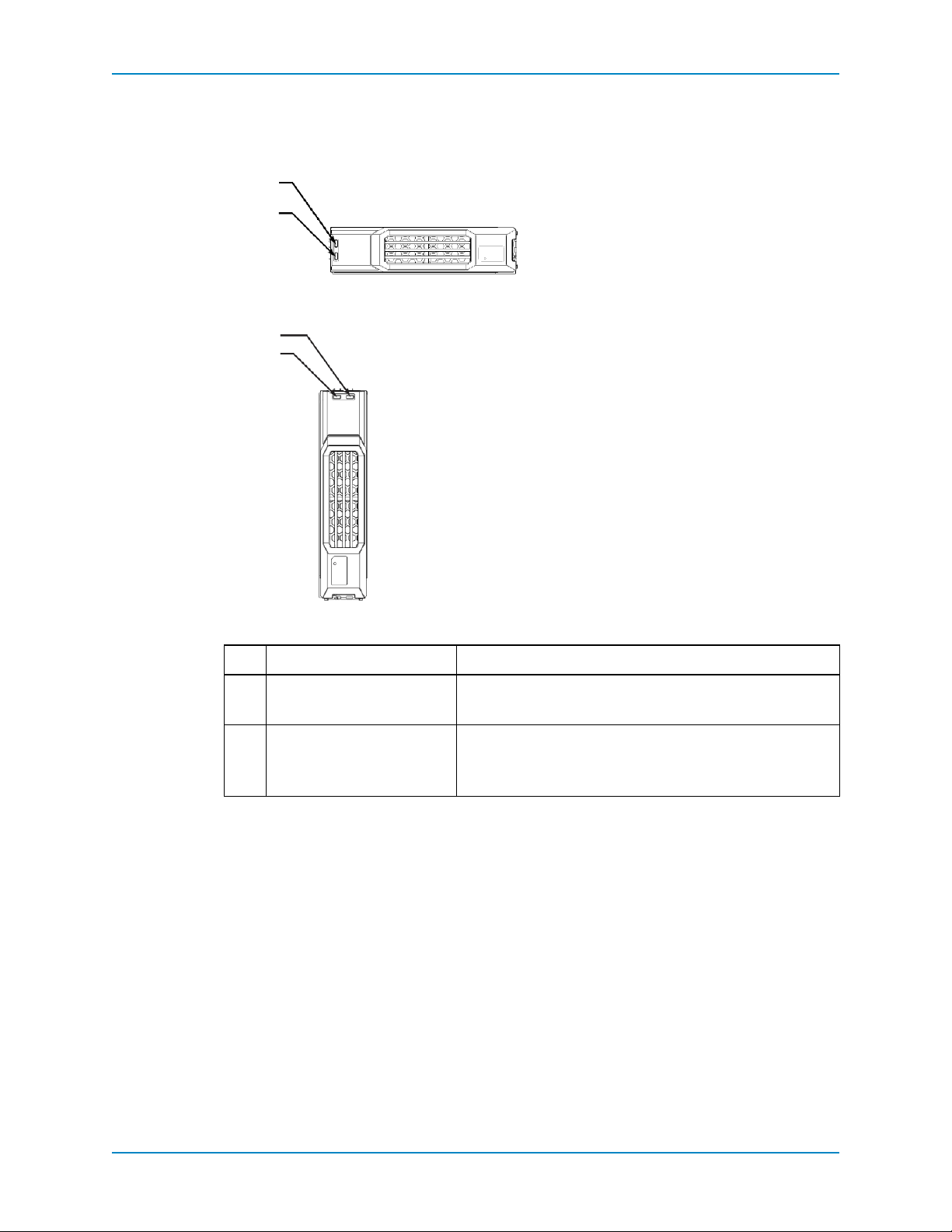
Front-Panel Features and Indicators
The front panel shows the enclosure and power status.
Figure 1. SC200 Front Panel Features and Indicators
Figure 2. SC220 Front Panel Features and Indicators
Item Name Icon Description
1 Enclosure status
indicator
2 Power status
indicator
2 Storage Center SC200 and S C2 20 En closures Service Gu ide
3 Hard drives • SC200: Up to 12 3.5-inch hard drives
Lights when the enclosure power is on.
• Off: No power
• On steady blue: Normal operation
• Blinking blue: Indicates that Storage Center is identifying
the enclosure
• On steady amber: Enclosure is turning on or was reset
• Blinking amber: Enclosure is in the fault state
Lights when at least one power supply is supplying power to the
enclosure.
• Off: Both power supplies are off
• On steady green: At least one power supply is providing
power to the enclosure
• SC220: Up to 24 2.5-inch hard drives
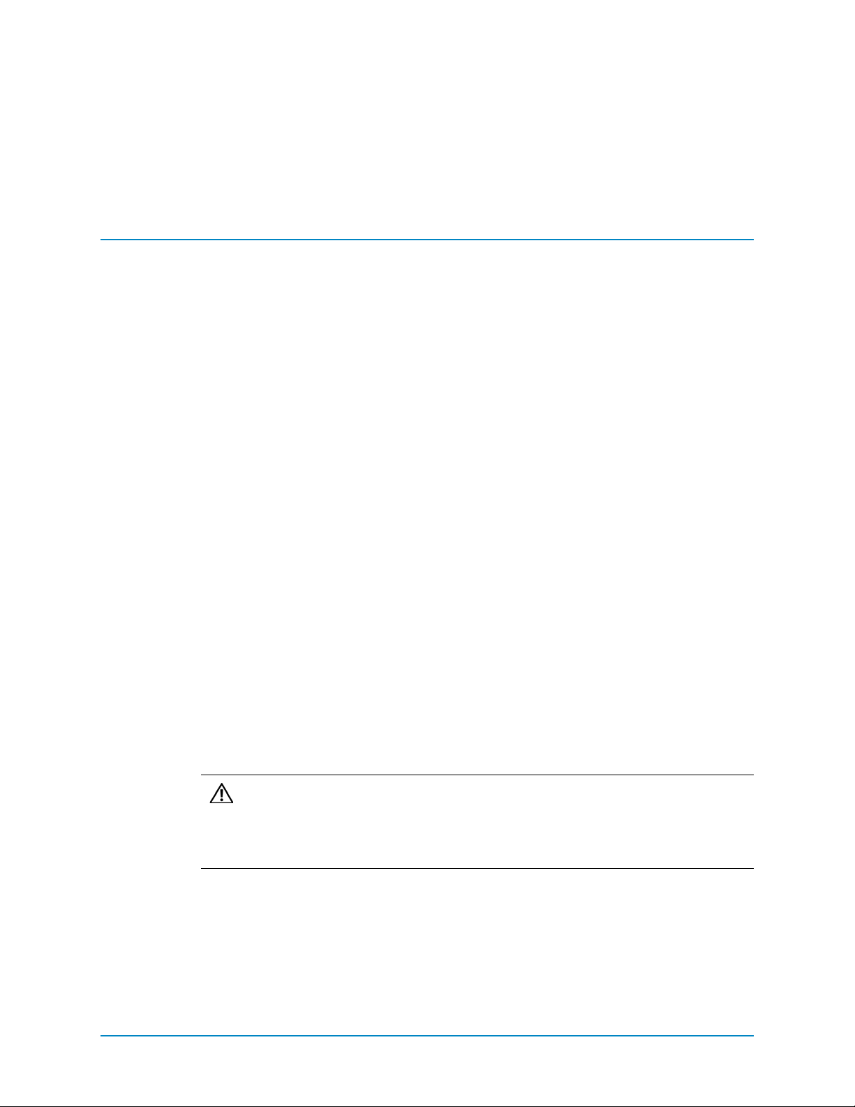
Back-Panel Features and Indicators
!
!
Compellent SC2
Compellent SC2
4
2
1
56
3
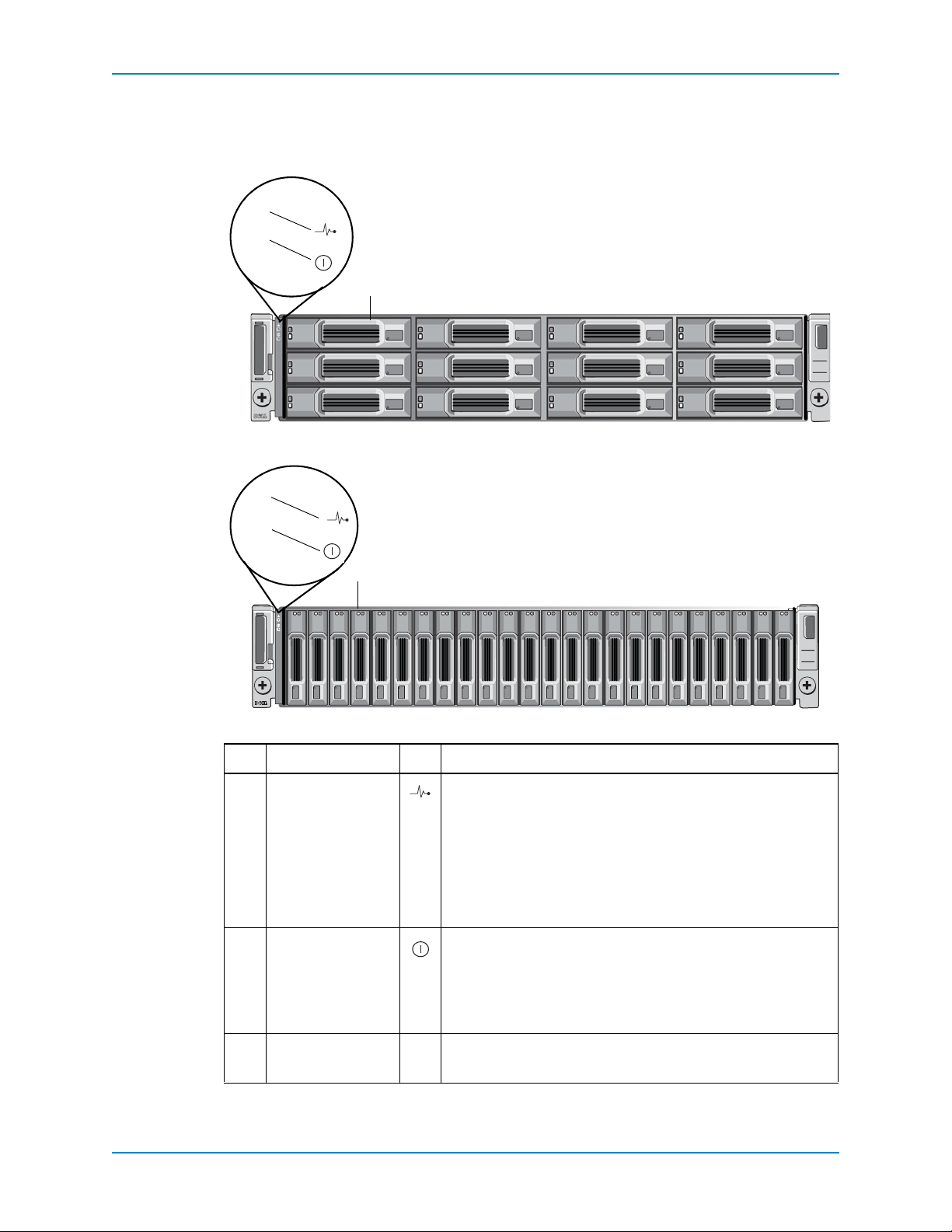
The back panel shows power indicators.
Back-Panel Features and Indicators
Figure 3. SC200/SC220 Back Panel Features and Indicators
Item Control/Feature Icon Description
1 DC power indicator • Green: Normal operation. The power supply
module is supplying DC power to the enclosure.
• Off: Power switch is off, the power supply is not
connected to AC power, or there is a fault condition
2 Power supply/cooling
fan indicator
3 AC power indicator • Green: Power supply module is connected to a
4 Power switches (2) Controls power for the enclosure. There is one switch
5 Power supply/cooling
fan modules (2)
6 Enclosure Management
Modules (2)
• Amber: Power supply/cooling fan fault is detected
• Off: Normal operation
source of AC power, whether or not the power
switch is on
• Off: Power supply module is disconnected from a
source of AC power
for each power supply/cooling fan module.
Contains a 700 W power supply and fans that provide
cooling for the enclosure
EMMs provide the data path and enclosure
management functions for the enclosure
Dell Compellent 3
Chapter 1 About the SC200/220
1
2
7
3
4
5
6
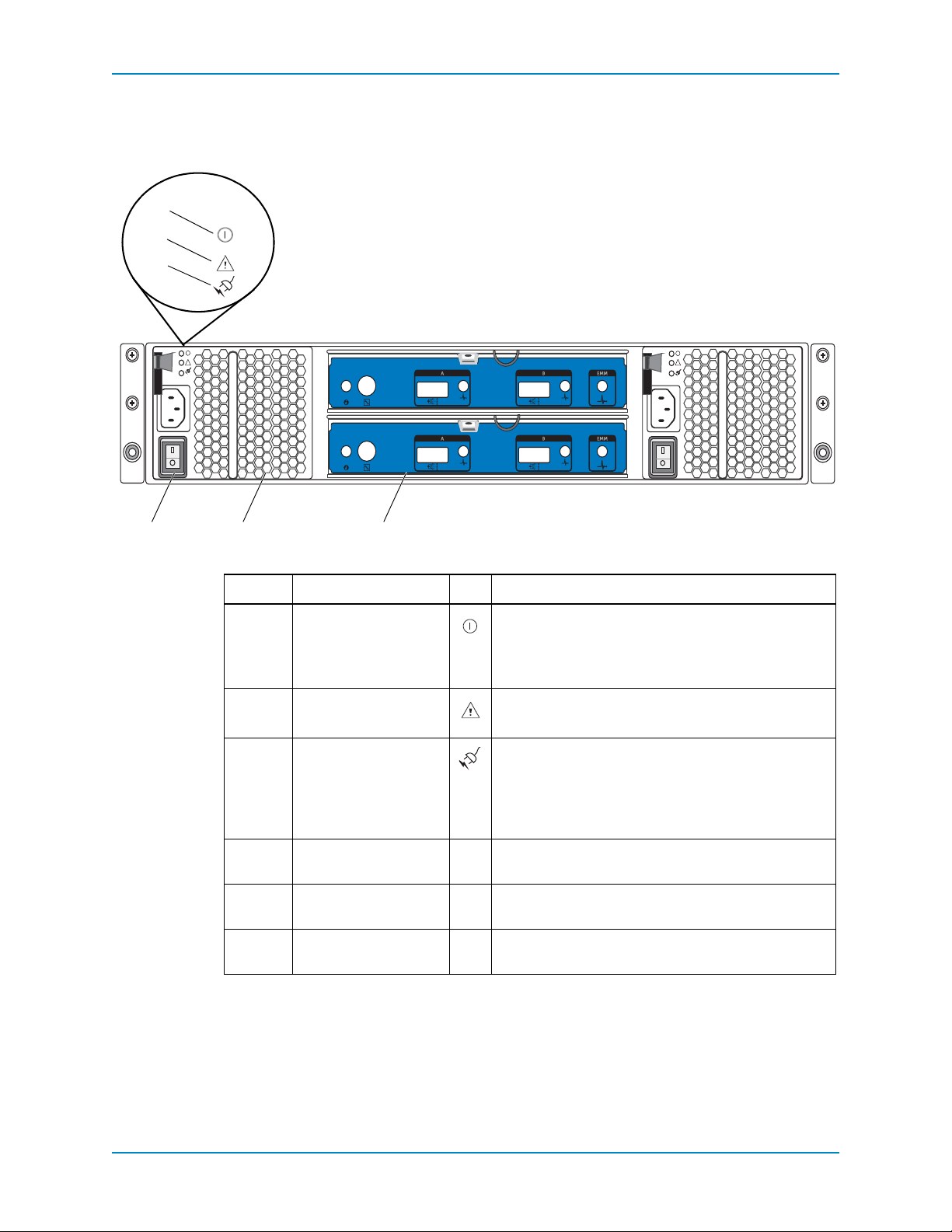
Enclosure Management Module Features and Indicators
SC200 and SC220 enclosures include two EMM IO modules in two interface slots.
Compellent SC2
Figure 4. SC200/SC220 EMM Features and Indicators
Item Control/Feature Icon Description
1 System status indicator Not used on SC200/SC220
2 Debug port For engineering use only
3 SAS port A (in) Connect to the controller or to other enclosures
4 In port link status
indicator
• Green: All the links to the port are connected
• Amber: One or more links are not connected
• Off: Enclosure is not connected
5 SAS Port B (out) Connect to the controller or to other enclosures
6 Out port link status
indicator
• Green: All the links to the port are connected
• Amber: One or more links are not connected
• Off: Enclosure is not connected
7 EMM status indicator • Steady green: Normal operation
• Amber: Enclosure did not boot or is not properly
configured
• Blinking green: Auto update in process
• Blinks amber twice: Enclosure is unable to
communicate with other enclosures
• Blinks amber four times: Firmware update failed
• Blinks amber five times: Firmware versions are
different between the two EMMs
4 Storage Center SC200 and S C2 20 En closures Service Gu ide
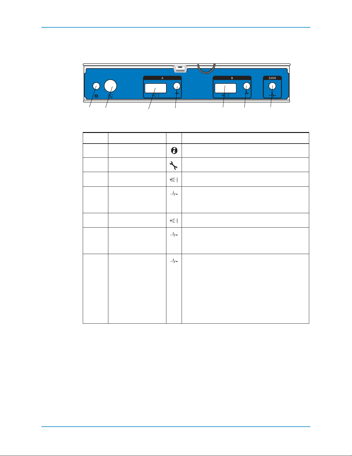
Hard Drive Indicators
2
1
2
1
The hard drives include status indicators.
Figure 5. SC200 Hard Drive Indicators
Hard Drive Indicators
Figure 6. SC220 Hard Drive Indicators
Item Feature Indicator Code
1 Hard drive activity indicator • Blinking green: Indicates drive activity
• Steady green: Indicates no drive activity
2 Hard drive status indicator • Steady green: Normal operation
• Off: No power to the drive
• Blinks amber four times per second: Drive failed
Dell Compellent 5

Chapter 1 About the SC200/220
6 Storage Center SC200 and S C2 20 En closures Service Gu ide
2 Replacing SC200/220 Components
This section describes how to replace field replaceable units (FRUs) insid e the SC200 and
SC220 enclosures. This document assumes the installer has already received and is ready
to install the appropriate replacement part in the enclosure.
Contents
Safety Precautions . . . . . . . . . . . . . . . . . . . . . . . . . . . . . . . . . . . . . . . . . . . . . . . . . . . . . 7
Pre-Replacement Procedures . . . . . . . . . . . . . . . . . . . . . . . . . . . . . . . . . . . . . . . . . . . . 8
Replacing the Front Bezel . . . . . . . . . . . . . . . . . . . . . . . . . . . . . . . . . . . . . . . . . . . . . . . 9
Replacing Power Supply/Cooling Fan Modules . . . . . . . . . . . . . . . . . . . . . . . . . . . . . . 10
Replacing Hard Drives . . . . . . . . . . . . . . . . . . . . . . . . . . . . . . . . . . . . . . . . . . . . . . . . . 13
Replacing an Enclosure Management Module . . . . . . . . . . . . . . . . . . . . . . . . . . . . . . . 17
Replacing the Control Panel . . . . . . . . . . . . . . . . . . . . . . . . . . . . . . . . . . . . . . . . . . . . . 19
Replacing the Backplane . . . . . . . . . . . . . . . . . . . . . . . . . . . . . . . . . . . . . . . . . . . . . . . 20
Replacing Rack Rails . . . . . . . . . . . . . . . . . . . . . . . . . . . . . . . . . . . . . . . . . . . . . . . . . . 23
Post-Replacement Procedures . . . . . . . . . . . . . . . . . . . . . . . . . . . . . . . . . . . . . . . . . . . 24
Safety Precautions
Always follow these safety precautions to avoid injury and damage to the enclosure.
Electrical Safety Precautions
Always follow electrical safety precautions to avoid injury and damage to the enclosure.
Warning: Disconnect power from the enclosure when removing or installing
components that are not hot-swappable. When disconnecting power, first power
down the controller(s) and enclosure(s) using the S tor age Center System Manage r
and then unplug the power cords from all the power supply/cooling fan modules in
the enclosure.
• Know the locations of the e quipment power switches and the room's emergency poweroff switch, disconnection switch, or electrical outlet.
• Do not work alone when working with hi gh voltage components.
• Do not use mats designed to decrease electrostatic discharge as protection from
electrical shock. Instead, use rubber mats that have been specifically designed as
electrical insulators.
Dell Compellent 7
 Loading...