

Dell SP2009W, SP2009Wc Service Manual
20" LCD Color Monitor Dell SP2009Wc
1
Service
Service
Service
Horizontal Frequency
30 kHz to 83 kHz
Table Of Contents
Description Page Description Page
SAFETY NOTICE
ANY PERSON ATTEMPTING TO SERVICE THIS CHASSIS MUST FAMILIARIZE HIMSELF WITH THE
CHASSIS AND BE AWARE OF THE NECESSARY SAFETY PRECAUTIONS TO BE USED WHEN SERVICING
ELECTRONIC EQUIPMENT CONTAINING HIGH VOLTAGES.
6.Mechanical Instruction………………..…..….......29
7.Schematic Diagram………..................................….....35
7.1Main Board......………......................................35
7.2 Power Board……..…….……....................................41
7.3 USB Board……………………………………………..43
7.4 Key Board………………………...…………………….44
8.PCB Layout..……...………….......................................45
8.1.Main Board……………..…........................................45
8.2.Power Board……………........................................47
8.3.USB Board………………….....................................48
9.Maintainability………….......................................49
9.1.Equipments and Tools Requirement..…….…...........49
9.2.Trouble Shooting………………….............................50
10.White-Balance, Luminance adjustment...………......56
11.ISP Instruction…………….…….................................58
12.Monitor Exploded View…………….…………............62
13.BOM List………….....................................................64
14.Different Parts List…………………….……………...85
Table Of Contents.......…….................……...........…........1
Revision List.….........................………................……......2
ECN History.….......................………..................……......3
Important Safety Notice.….……….…..................……......4
1.Monitor Specifications.....…........................………........5
2.LCD Monitor Description…………………………….......6
3.Operation Instructions……………...............……...........7
3.1.General Instructions…………………………………….7
3.2.Control Buttons……………...............……...............8
3.3 Adjusting the Picture...........…………….........………..9
4.Input/Output Specification.............……………........…20
4.1.Input Signal Connector............………….................20
4.2.Factory Preset Display Modes...…..…......................21
4.3.Power Supply Requirements..........……...................21
4.4.Panel Specification…….....……………..................22
4.5.Definition of Pixel Defects…………...............……….23
5.Block Diagram…….…...................…………................25
5.1.Software Flow Chart………..………………....….......25
5.2.Electrical Block Diagram………………..…..….......27
20" LCD Color Monitor Dell SP2009Wc
2
Revision List
Revision Release Date Revise history TPV model
A00 May.-15-2008 Initial Release
TA8CMUHKWMDDBZ
TA8GMUHKWMDDBZ
TA8GMUNMWMDDBC
TA8GMUNLWMDLBC
TA8CMUNLWMDLBC
TA8GMUNJWMDDBC
TA8CMUNJWMDDBC
TA8GMUNMWMDLBC
TA8CMUNMWMDLBC
TA8GMUNFWMDLBC
TA8CMUNFWMDLBC
A01 Jun.-5-2008
Add “Camera & Microphone test
sop” in item 6
ALL
A02 Jul.-05-2008 Add TPV Model in item 13&14
TA8GMUHKWMDDBC
TA8GMUNKWMDDBC
TA8CMUNKWMDDBC
TA8GMUNKWMDDBZ
TA8CMUNKWMDDBZ
TA8GMUNBWMDDBC
TA8CMUNBWMDDBC
TA8GMUNBWMDDBZ
TA8CMUNBWMDDBZ
TA8GMUNBWMDD4C
TA8CMUNBWMDD4C
A03 Dec.-02-2008 Add TPV Model in item 14
TA8GMUNKWMDRBZ
A04 Dec.-22-2008
Change Y value to Ymin (min
luminance value)in item 10
ALL
20" LCD Color Monitor Dell SP2009Wc
3
ECN History
ECN No. Change Description Service Deposition Cut-in date MSR

20" LCD Color Monitor Dell SP2009Wc
4
Important Safety Notice
Proper service and repair is important to the safe, reliable operation of all AOC Company Equipment. The service
procedures recommended by AOC and described in this service manual are effective methods of performing
service operations. Some of these service operations require the use of tools specially designed for the purpose.
The special tools should be used when and as recommended.
It is important to note that this manual contains various CAUTIONS and NOTICES which should be carefully read
in order to minimize the risk of personal injury to service personnel. The possibility exists that improper service
methods may damage the equipment. It is also important to understand that these CAUTIONS and NOTICES ARE
NOT EXHAUSTIVE. AOC could not possibly know, evaluate and advise the service trade of all conceivable ways in
which service might be done or of the possible hazardous consequences of each way. Consequently, AOC has not
undertaken any such broad evaluation. Accordingly, a servicer who uses a service procedure or tool which is not
recommended by AOC must first satisfy himself thoroughly that neither his safety nor the safe operation of the
equipment will be jeopardized by the service method selected.
Hereafter throughout this manual, AOC Company will be referred to as AOC.
WARNING
Use of substitute replacement parts, which do not have the same, specified safety characteristics may create
shock, fire, or other hazards.
Under no circumstances should the original design be modified or altered without written permission from AOC.
AOC assumes no liability, express or implied, arising out of any unauthorized modification of design.
Servicer assumes all liability.
FOR PRODUCTS CONTAINING LASER:
DANGER-Invisible laser radiation when open. AVOID DIRECT EXPOSURE TO BEAM.
CAUTION-Use of controls or adjustments or performance of procedures other than those specified herein may
result in hazardous radiation exposure.
CAUTION -The use of optical instruments with this product will increase eye hazard.
TO ENSURE THE CONTINUED RELIABILITY OF THIS PRODUCT, USE ONLY ORIGINAL MANUFACTURER'S
REPLACEMENT PARTS, WHICH ARE LISTED WITH THEIR PART NUMBERS IN THE PARTS LIST SECTION
OF THIS SERVICE MANUAL.
Take care during handling the LCD module with backlight unit
-Must mount the module using mounting holes arranged in four corners.
-Do not press on the panel, edge of the frame strongly or electric shock as this will result in damage to the screen.
-Do not scratch or press on the panel with any sharp objects, such as pencil or pen as this may result in damage to
the panel.
-Protect the module from the ESD as it may damage the electronic circuit (C-MOS).
-Make certain that treatment person’s body is grounded through wristband.
-Do not leave the module in high temperature and in areas of high humidity for a long time.
-Avoid contact with water as it may a short circuit within the module.
-If the surface of panel becomes dirty, please wipe it off with a soft material. (Cleaning with a dirty or rough cloth
may damage the panel.)
20" LCD Color Monitor Dell SP2009Wc
5
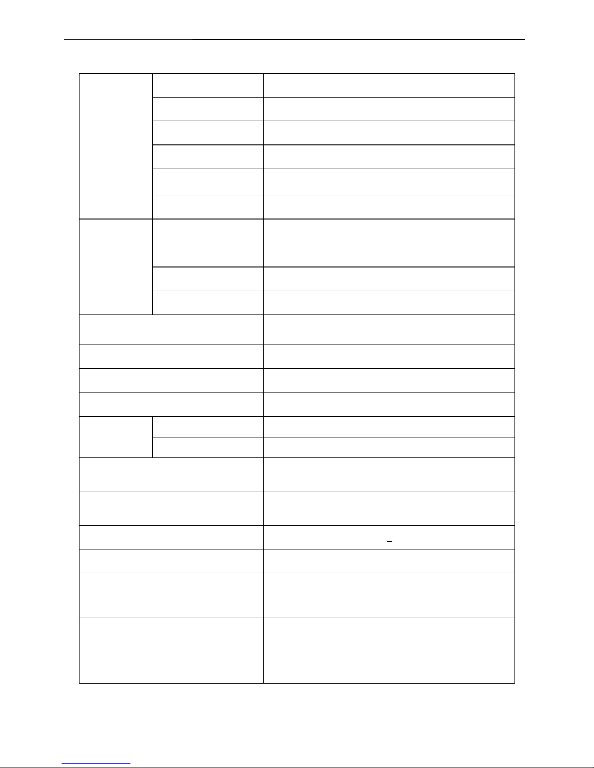
1. Monitor Specifications
Screen type Active matrix - TFT LCD
Panel Type
CLAA201WA04A 336 FZ CPT
Size
20.1 inches (20.1-inch viewable image size)
Pixel pitch
0.258 mm (H) x 0.258mm(V)
Viewable angle
160° (vertical) typ, 160° (horizontal) typ
LCD Panel
Response time 2 ms typical (Grey to Grey)
Video R, G, B Analog Interface, DVI digital Interface
Separate Sync H/V TTL
H-Frequency 30kHz – 83kHz
Input
V-Frequency 53 - 76Hz
Dynamic contrast ratio 2000:1 (typical)
Luminance output 300 CD/m ²(typical)
Max. Resolution
1680 x 1050 at 60 Hz
Plug & Play VESA DDC
ON Mode <45W
EPA ENERGY
STAR
®
OFF Mode <1W
Input Connector
15-pin D-subminiature, blue connector;
DVI-D, white connector
Preset display area:
Height : 393.10 mm (15.48 inches)
Width: 481.50mm (18.96 inches)
Power Source
100 to 240 VAC / 50 or 60 Hz +
3 Hz / 1.5A
Video display capabilities (DVI playback) 480i/480p/576i/576p/1080i/1080p (Supports HDCP)
Environmental
Considerations
Operating Temp: 5° to 35°C
Operating Humidity: 10% to 80%
Storage Temp.: -20° to 60°C
Weight
Weight with packaging: 18.70 lbs (8.50 kg)
Weight with stand assembly and cables: 13.64 lbs (6.20 kg)
Weight without stand assembly: 10.56 lbs (4.8 kg)
Weight of stand assembly: 2.93 lbs (1.34 kg)
20" LCD Color Monitor Dell SP2009Wc
6
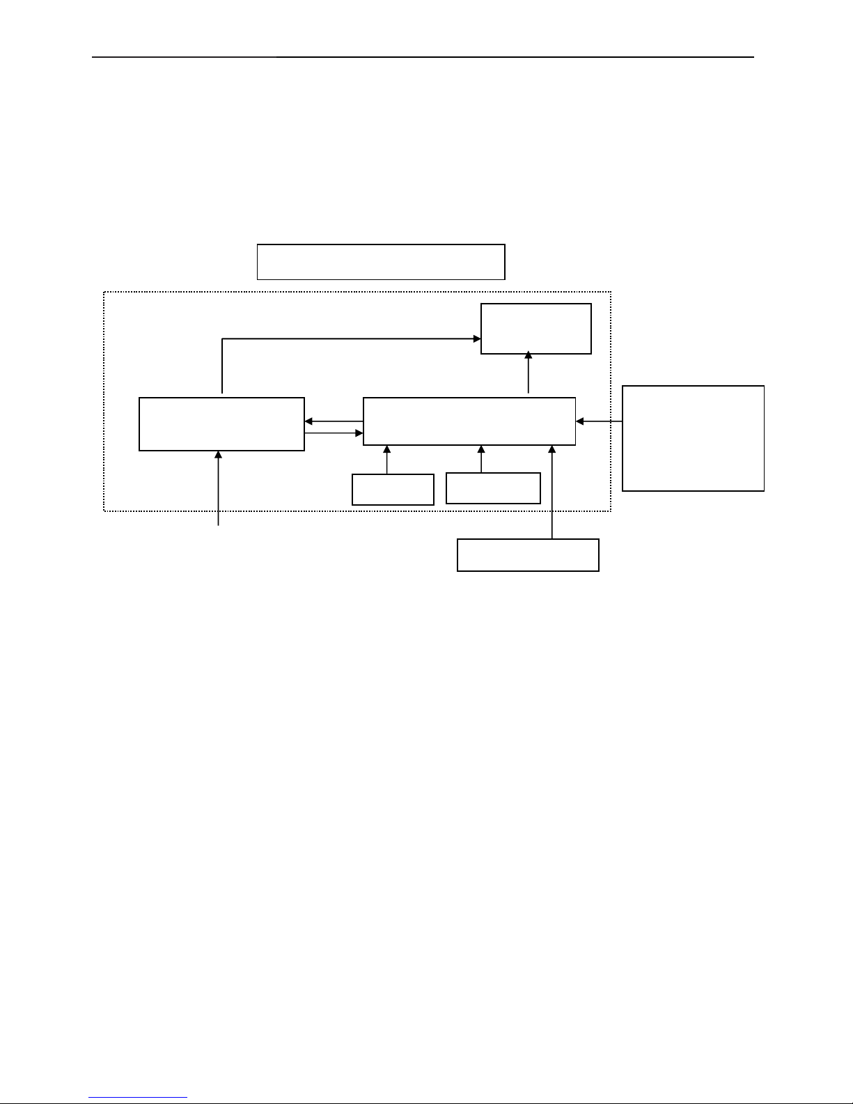
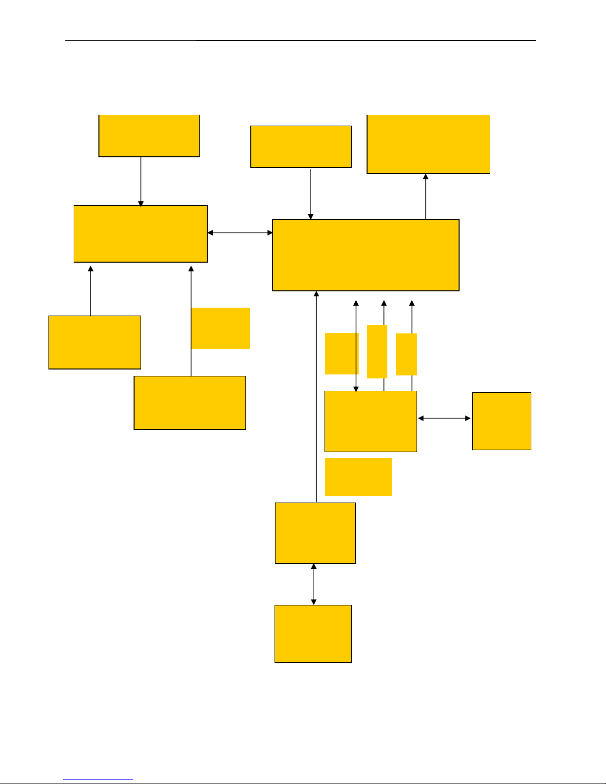
2. LCD Monitor Description
The LCD monitor will contain a main board, power board, key board and a USB board which house the flat
panel control logic, brightness control logic and DDC.
The power board will provide AC to DC Inverter voltage to drive the backlight of panel and the main board
chips each voltage.
Video signal, DDC
Power board
Flat Panel and
CCFL backlight
Main Board
Key board
RS232 Connector
For white balance
adjustment in factory
mode
CCFL Drive.
AC-IN
100-240V
Monitor Block Diagram
Host Computer
USB board
20" LCD Color Monitor Dell SP2009Wc
7
3. Operation instructions
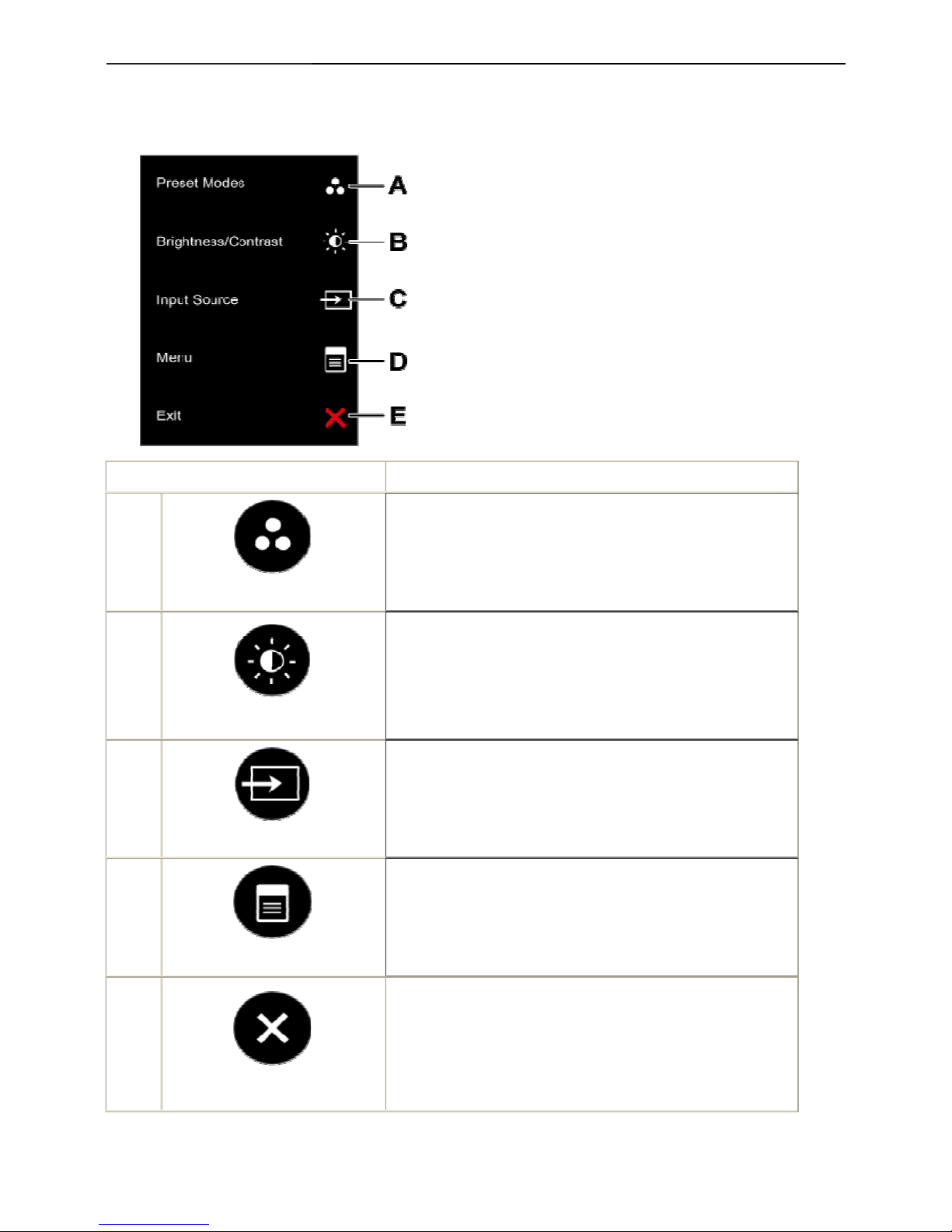
3.1 Using the Front Panel Controls
Use the buttons on the front of the monitor to adjust the image settings.
Front panel Button Description
A
Preset modes
Use the Preset modes button to choose from a list of preset color
modes.
B
Brightness / Contrast
Use the Brightness / Contrast button to direct access to the
"Brightness" and "Contrast" control menu.
C
Input source
Use the Input source button to select different video signals that may
be connected to your monitor.
D
Menu
Use the Menu button to open the on-screen display(OSD).
E
Exit
Use the Exit button to exit on-screen display(OSD) from menu and
sub-menus.
Use the buttons on the front of the monitor to adjust the image settings.
20" LCD Color Monitor Dell SP2009Wc
8
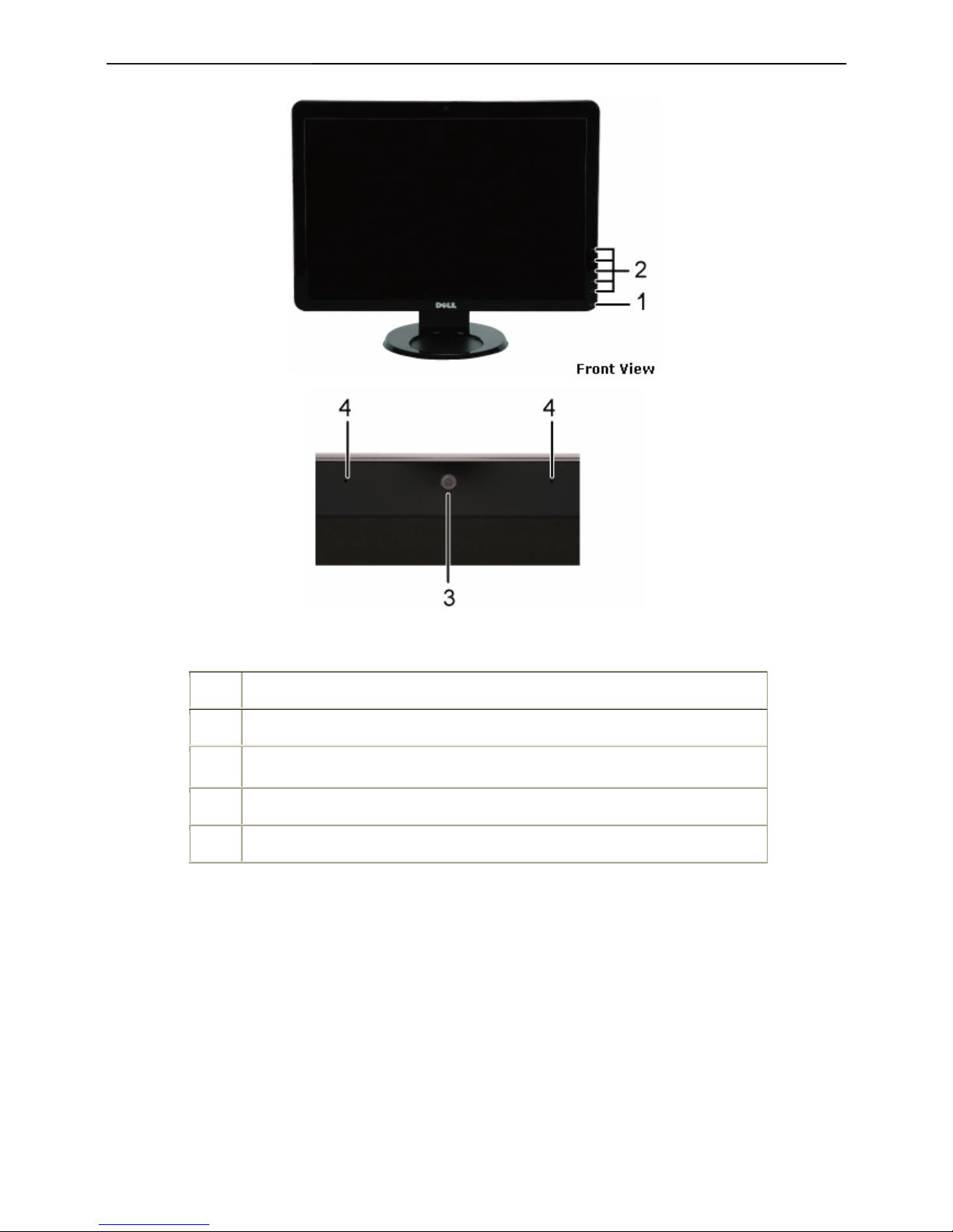
3.2 Control Buttons
Label Description
1 Power button
2 Capacitive touch buttons (For more information, see Operating the Monitor)
3 Webcam
4 Microphone
20" LCD Color Monitor Dell SP2009Wc
9
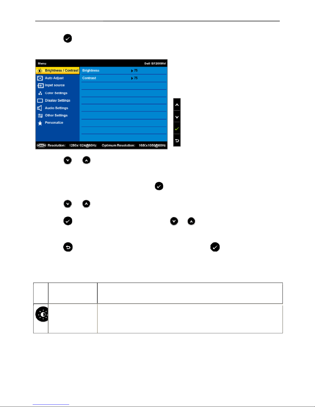
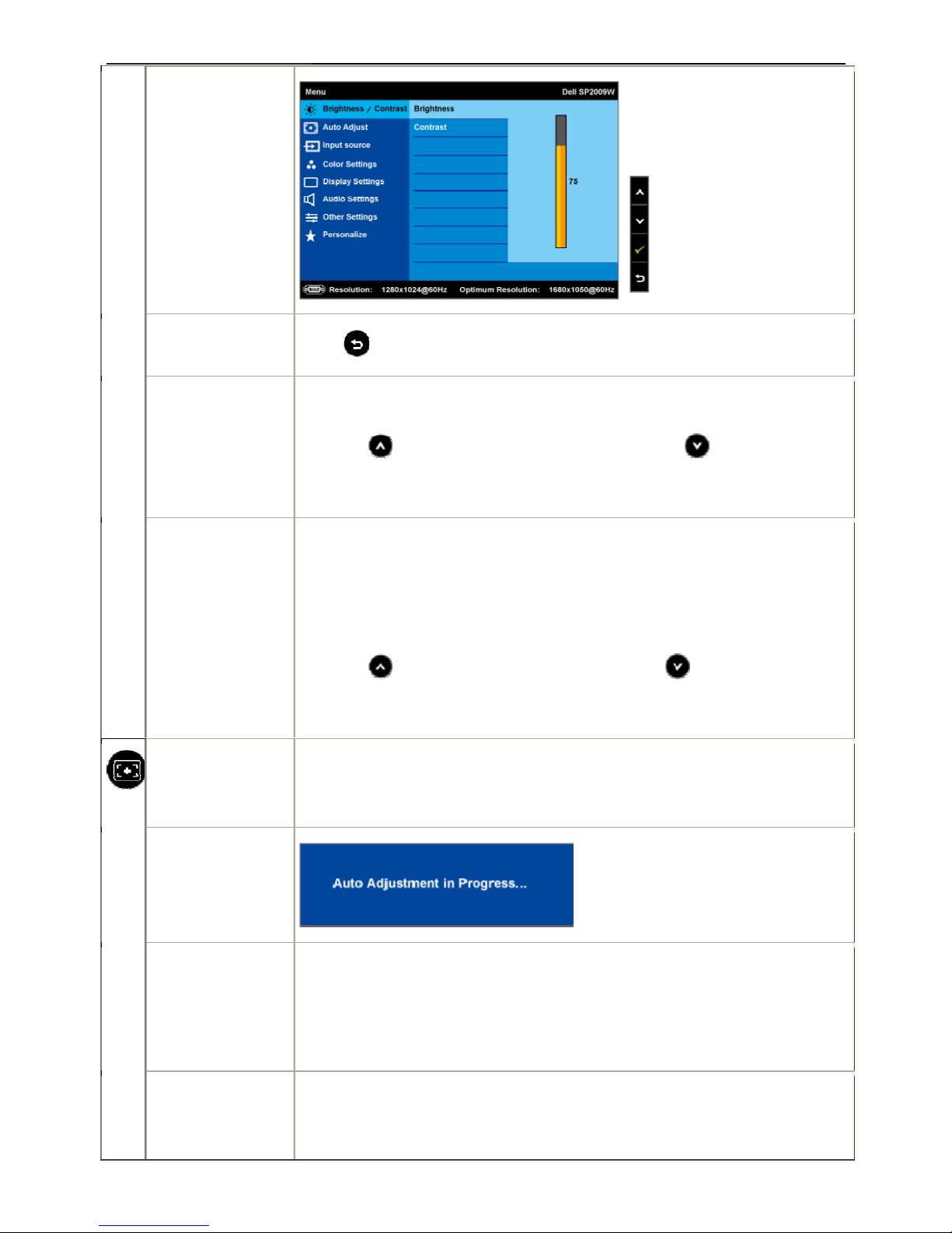
3.3 Adjusting the Picture
1. Press the button to open the OSD menu and display the main menu.
Main Menu
2. Press the
and buttons to toggle between options in the Menu. As you move from one icon to another,
the option name is highlighted.
3. To select the highlighted item on the menu press the
again.
4. Press the
and buttons to select the desired parameter.
5. Press the
button to enter the slide bar and then use the or button, according to the indicators on
the menu, to make your changes.
6.Select the
to return to previous menu without accepting current settings or to accept and return to
previous menu.
The table below provides a list of all the OSD menu options and their functions.
Icon Menu and
Submenus
Description
BRIGHTNESS/CON
TRAST
Use the Brightness and Contrast menu to adjust the Brightness/Contrast.
20" LCD Color Monitor Dell SP2009Wc
10
Back
Press
to go back to the main menu.
Brightness
Allows you to adjust the brightness or luminance of the backlight.
Press the
button to increase brightness and press the button to
decrease brightness (min 0 ~ max 100).
Contrast
Allows you to adjust the contrast or the degree of difference between
darkness and lightness on the monitor screen. Adjust brightness first, and
adjust contrast only if you need further adjustment.
Press the
button to increase contrast and press the button
to decrease contrast (min 0 ~ max 100).
Auto Adjust
Use this button to activate automatic setup and adjust menu. The following dialog
appears on a black screen as the monitor self-adjusts to the current input:
Auto Adjustment allows the monitor to self-adjust to the incoming video signal.
After using Auto Adjustment, you can further tune your monitor by using the Pixel
Clock (Coarse) and Phase (Fine) controls under Image Settings.
NOTE: Auto Adjust does not occur if you press the button while there are no active
video input signals or attached cables.
20" LCD Color Monitor Dell SP2009Wc
11
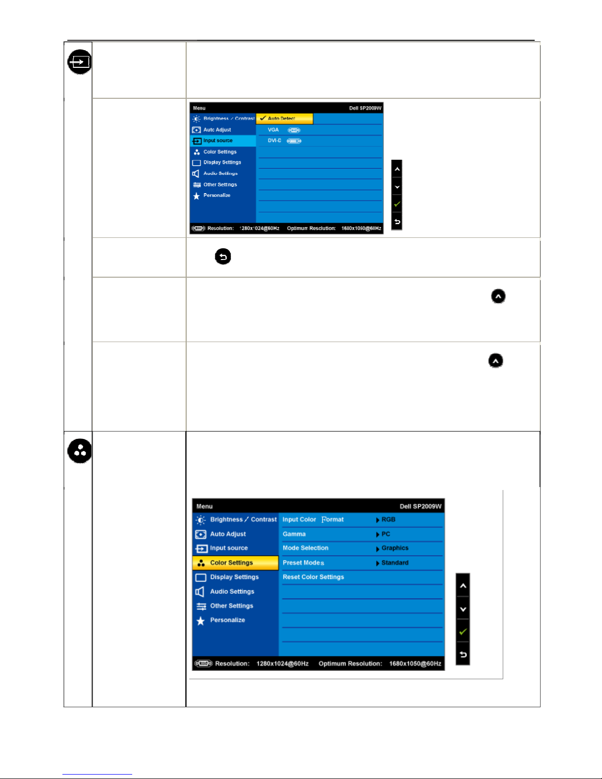
Input Source
Use the Input Source menu to select different video signals that may be connected
to your monitor.
Push
to go back to the main menu
Select VGA input when you are using the analog (VGA) connector. Push
to
select the VGA input source.
Select DVI-D input when you are using the digital (DVI) connector. Push
to
select the DVI input source.
Select Auto select to let the monitor search for available input signals.
COLOR SETTINGS
Use the Color Setting menu to adjust the monitor's color settings.
Color setting mode
submenu
20" LCD Color Monitor Dell SP2009Wc
12
Back
Press
to go back to the main menu.
Input Color Format
Allows you to set the video input mode to.
• RGB: Select this option if your monitor is connected to a computer or DVD
• player using the HDMI cable or the HDMI to DVI adapter.
• YPbPr: Select this option if the your DVD player supports only YPbPr output.
Mode Selection
Allows you to set the display mode to:
• Graphics: Select this mode if your monitor is connected to your computer.
• Video: Select this mode if you monitor is connected to a DVD player.
NOTE: Depending upon the Display Mode you select the Preset Modes available
for your monitor change.
Preset Mode
Allows you to choose from a list of preset color modes.
In the Graphics mode, you can set the color to the following preset values:
• Standard: Loads the monitor's default color settings. This is the default
preset mode.
• Multimedia: Loads color settings ideal for multimedia applications.
• Game: Loads color settings ideal for most gaming applications.
• Warm: Increase the color temperature. The screen appears warmer with
a red/yellow tint.
• Cool: Decreases the color temperature. The screen appears cooler with
• a blue tint.
• Custom (RGB): Allows you to manually adjust the color settings. Press
the
and buttons to adjust the Red, Green, and
Blue values and create your own preset color mode.
In the Video mode, you can set the color to the following preset values:
• Movie: Loads color settings ideal for movies. This is the default preset mode.
• Game: Loads color settings ideal for most gaming applications.
20" LCD Color Monitor Dell SP2009Wc
13
• Sports: Loads color settings ideal for sports.
• Nature: Loads color settings ideal for nature.
Hue
Allows you to adjust the skin tone of the image. Use
or to adjust the hue
from '0' to '100'.
NOTE: Hue adjustment is available only in the Video mode.
Saturation
Allows you to adjust the color saturation of the image. Use
or to adjust
the saturation from '0' to '100'.
NOTE: Saturation adjustment is available only in the Video mode.
Color Reset
Resets your monitor's color settings to the factory defaults.
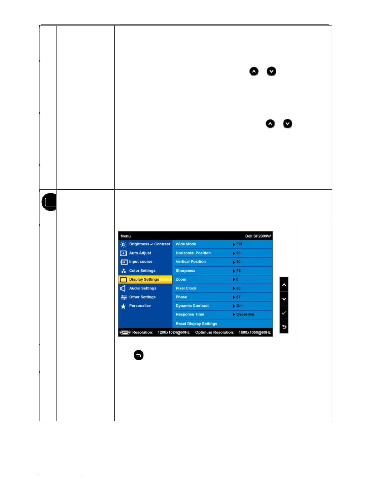
DISPLAY
SETTINGS
Use the Displays Settings menu to adjust the sharpness, dynamic contrast,
response time, and zoom.
Display setting
mode submenu
Back
Press
to go back to the main menu.
Wide Mode
Allows you to change the image scale with various default settings.
NOTE: Wide Mode is not available at video resolutions greater than 1680x1050.
However, 16:9 and Fill will be available for video timing.
20" LCD Color Monitor Dell SP2009Wc
14
Horizontal position
Use the
and buttons to adjust image left and right (min 0 ~ max 100).
NOTE: When using DVI source, the Horizontal Position setting is not available.
Vertical Position
Use the
and buttons to adjust image up and down (min 0 ~ max 100).
NOTE: When using DVI source, the Vertical Position setting is not available.
Zoom
Allows you to zoom in to specific area of interest on your monitor.
Use
and buttons to adjust the zoom from '0' to '100'.
NOTE: Zoom will reset to default after power cycling or after power save recovery.
NOTE: Zoom default setting will be zero when using PC format (RGB color space)
and 10 when using the video format from DVD players (YPbPr color space).
Phase
If satisfactory results are not obtained using the phase adjustmenu, use the
Pixel Clock (coarse) adjustmenu and then use Phase (fine).
NOTE: Pixel Clock and Phade Adjustments are only available for "VGA" input.
Sharpness
Allows you to increase or decrease the sharpness of the image.
Use
and buttons to adjust the sharpness from '0' to '100'.
Dynamic Contrast
The dynamic contrast helps get a higher contrast if you choose Game preset,
Movie Preset, Sports Preset and Nature Preset.
Use the
button to enable the Dynamic Contrast adjustment.
Use the button to disable the Dynamic Contrast adjustment.
NOTE: Brightness control is disabled in Dynamic Contrast mode.
Response Time
Response time is the time required for an LCD pixel to change from fully
active (black) to fully inactive (white), then back to fully active again.
You can set the response time to:
20" LCD Color Monitor Dell SP2009Wc
15
• Normal
• Overdrive (default).
Display Reset
Resets the monitor's display settings to the factory defaults.
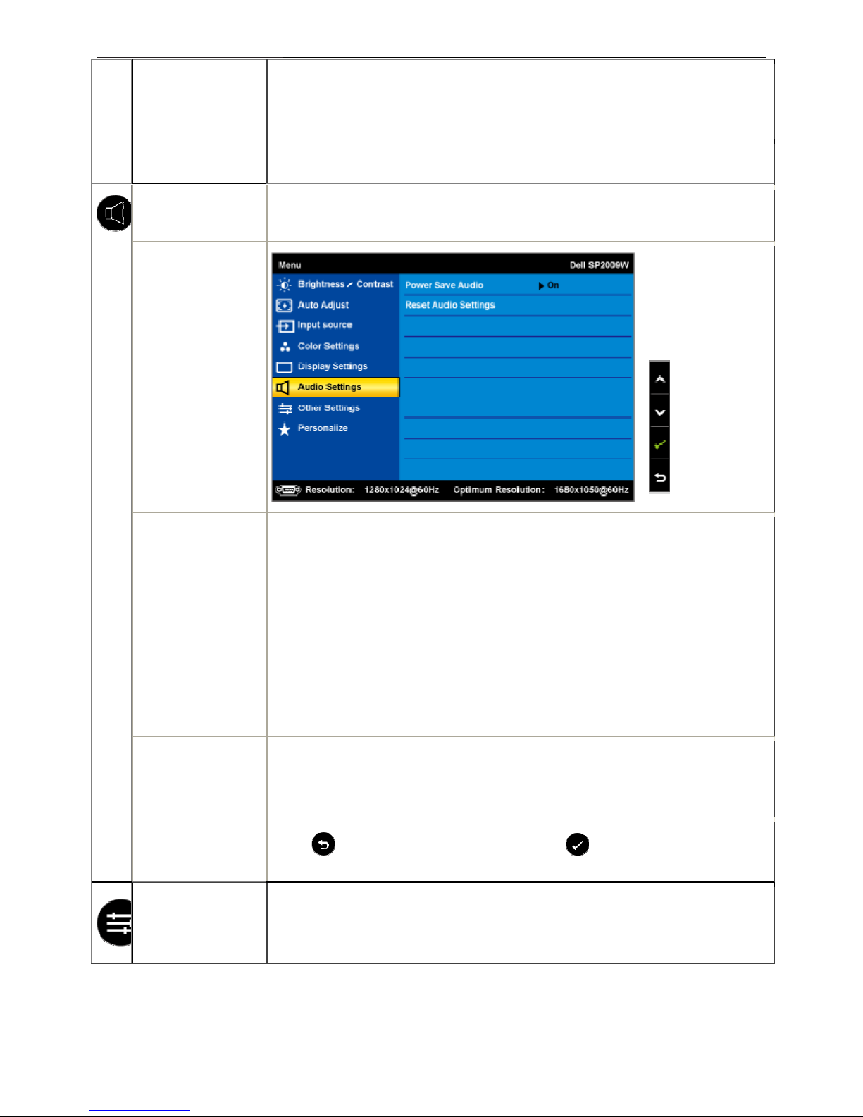
AUDIO SETTINGS
Use the Audio Settings to adjust the audio settings.
Audio Setting
mode submenu
Power Save Audio
Allows you to turn on or off the power to the audio during the audio
power save
mode.
Default is "On".
On — Allows you to turn off the power to the sound bar during monitor standby.
Off — Allows you to turn on the power to the sound bar during monitor standby.
Reset Audio
Setting
Resets your monitor audio settings to the factory defaults.
Exit Menu
Press
to exit the OSD main menu and press to accept changes.
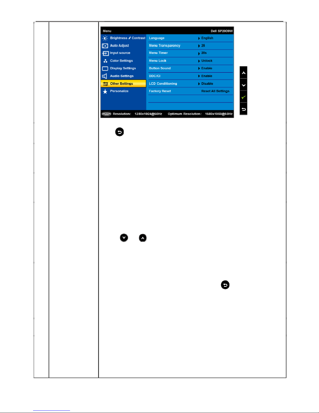
OTHER SETTINGS
20" LCD Color Monitor Dell SP2009Wc
16
Back
Press
to go back to the main menu.
Language
Allows you to set the OSD display to one of five languages: English, Espanol,
Francais, Deutsch, or Japanese.
Menu
Transparency
Allows you to adjust the OSD background from opaque to transparent.
Menu Timer
Allows you to set the time for which the OSD remains active after you press a
button on the monitor.
Use the
and buttons to adjust the slider in 1 second increments, from
5 to 60 seconds.
Menu Lock
Controls user access to adjustments. When Lock is selected, no user
adjustments are allowed. All buttons are locked except
button.
Button Sound
Turns on or off the button sound.
DDC/CI
DDC/CI (Display Data Channel/Command Interface) allows a software on your
computer to adjust the monitor display settings like the brightness, color balance etc.
Enable (Default): Optimizes the performance of your monitor and provides a better
20" LCD Color Monitor Dell SP2009Wc
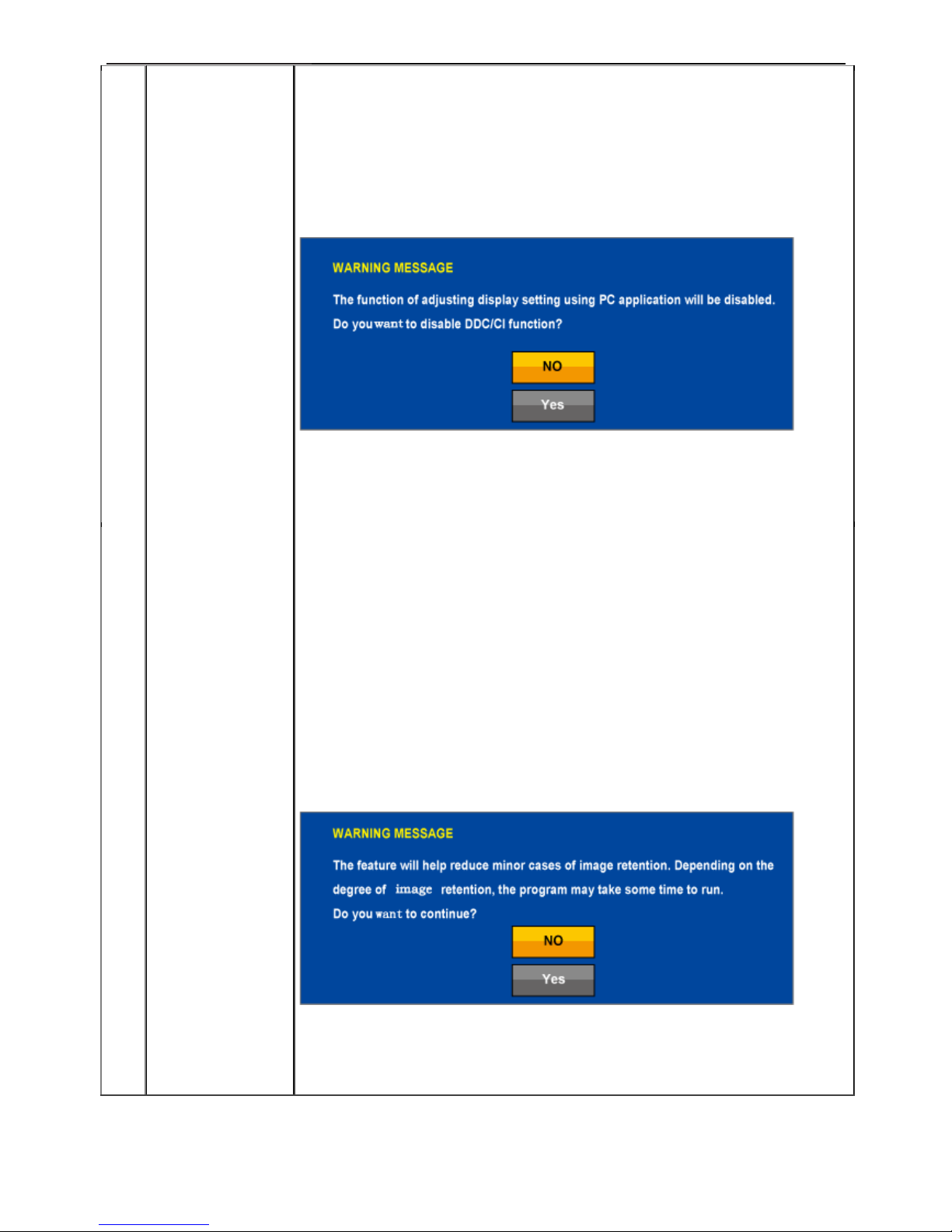
17
customer experience.
Disable: Disables the DDC/CI option and the following message appears
on the screen.
Select Yes to disable DDC/CI or No to return.
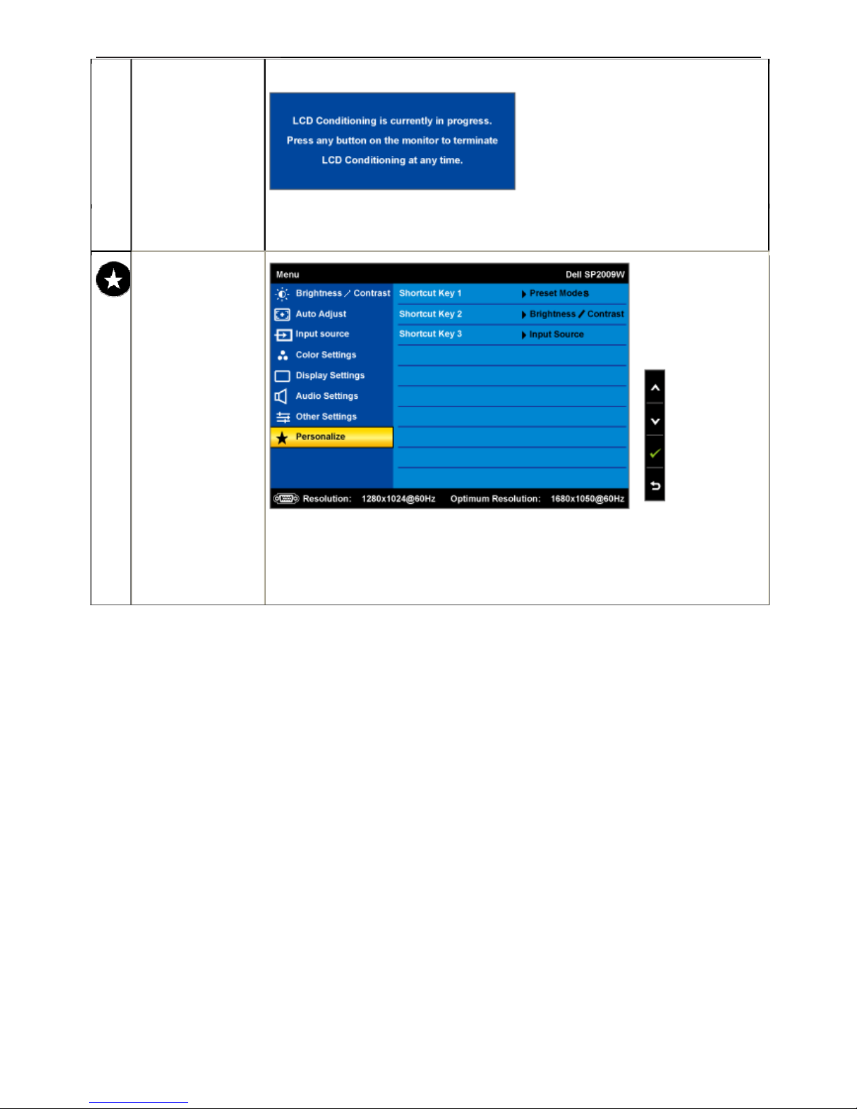
LCD Conditioning
LCD conditioning helps eliminate any image retention and may take several hours.
NOTE: Severe cases of image retention are known as burn-in. LCD Conditioning
does not remove burn-in.
Disable: This is the default option.
Enable: Enables LCD conditioning and the following message appears on the
screen.
Select Yes to proceed and No to return.
NOTE: Press any button on the monitor to terminate LCD Conditioning at any time.
20" LCD Color Monitor Dell SP2009Wc
18
Factory Reset
Resets all OSD settings to the factory preset values.
Personalize
Allow you to adjust shortcut key button for preset mode. Brightness & Contrast
Auto Adjust and Input source.
20" LCD Color Monitor Dell SP2009Wc
19
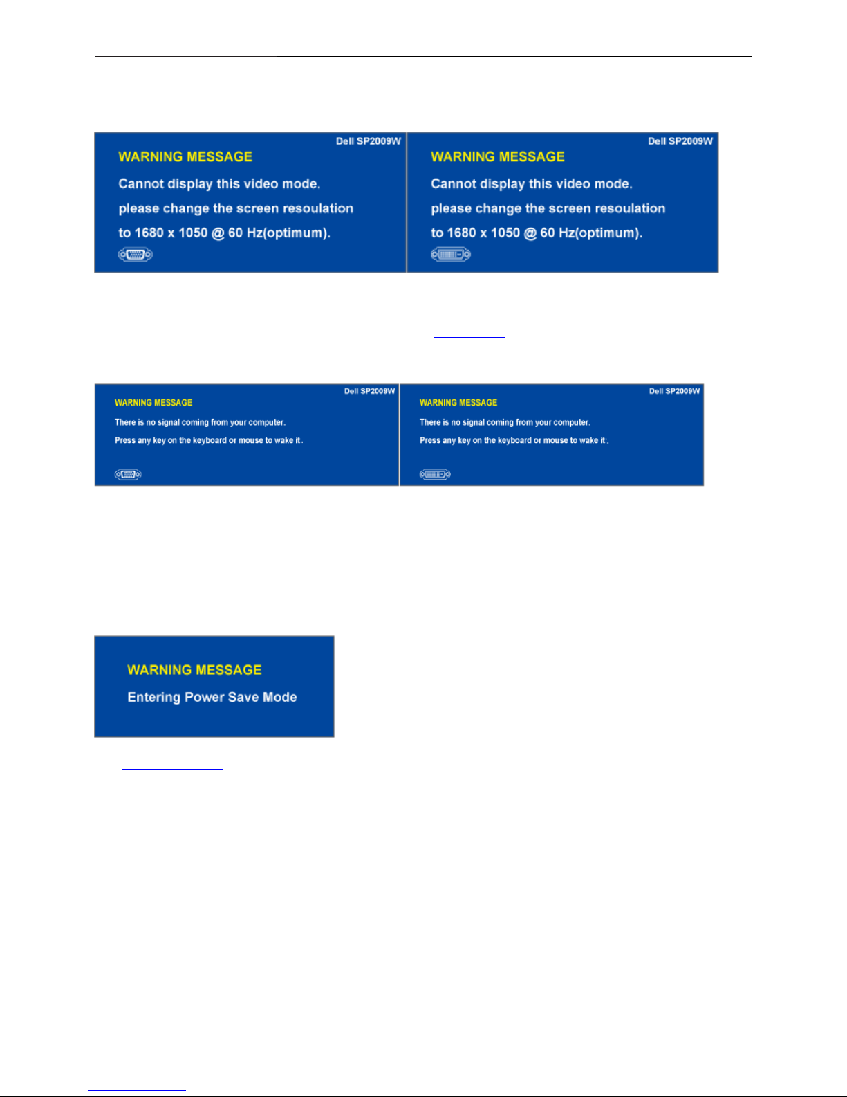
OSD Warning Messages
The following warning messages may appear on the screen to indicate that the monitor is out of synchronization.
This means that the monitor cannot synchronize with the signal that it is receiving from the computer.
Either the signal is too high or too low for the monitor to use. See Specifications for the Horizontal and
Vertical frequency ranges addressable by this monitor. Recommended mode is 1680 X 1050 at 60Hz.
If you press any button other than the power button one of the following messages will appear depending on
the selected input:
When monitor enters Power Save mode, the following message appears :
See Solving Problems
for more information.
20" LCD Color Monitor Dell SP2009Wc
21
4. Input/Output Specification
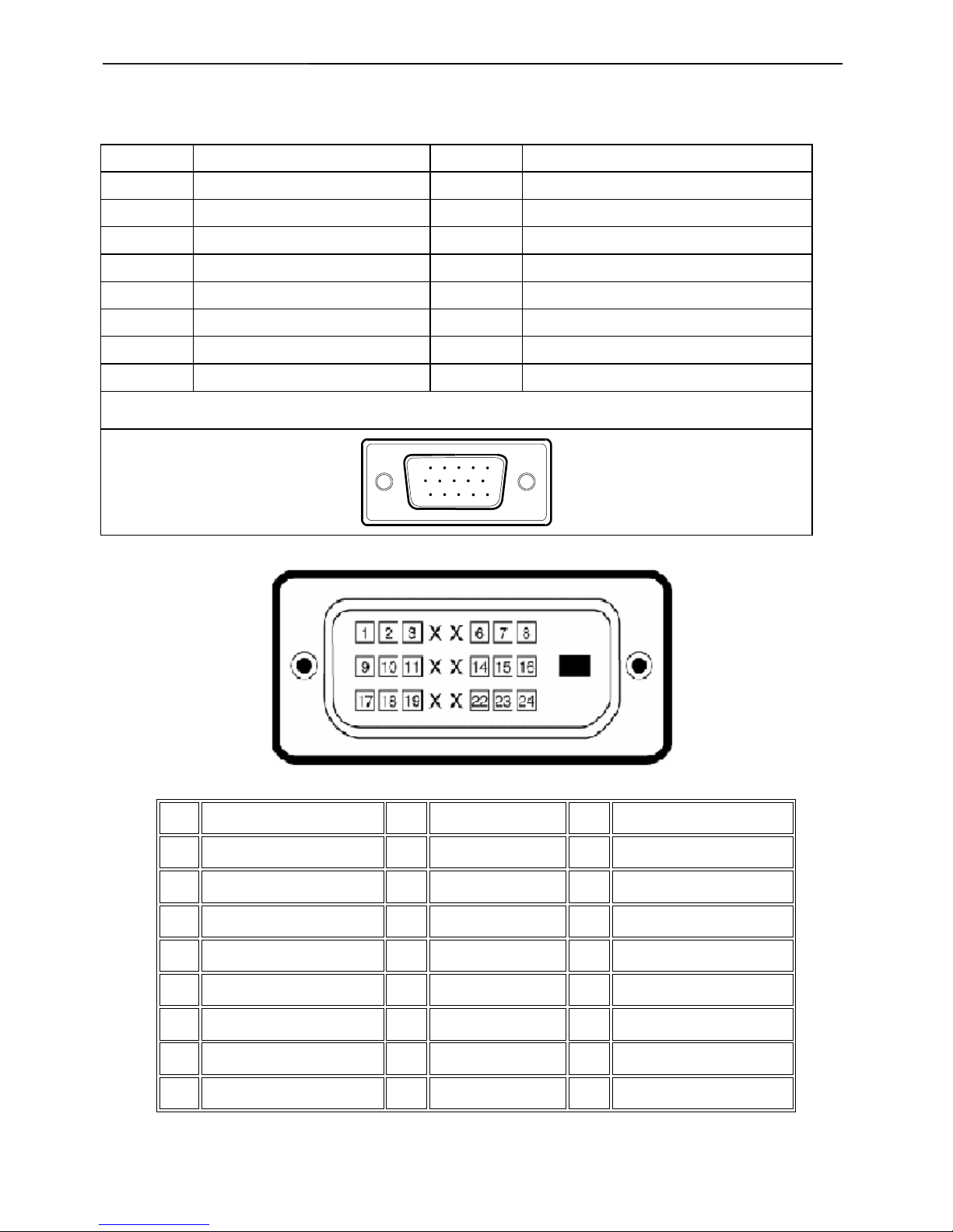
4.1 Input Signal Connector
VGA Connector:
Pin No. Description Pin No. Description
1. Red Video 9. DDC +5V
2. Green Video 10. GND-sync
3. Blue Video 11. GND
4. GND 12. DDC data
5. Self-test 13. H-Sync
6. R-Ground 14. V-Sync
7. G-Ground 15. DDC clock
8. B-Ground
VGA Connector layout
15
6
10
11 15
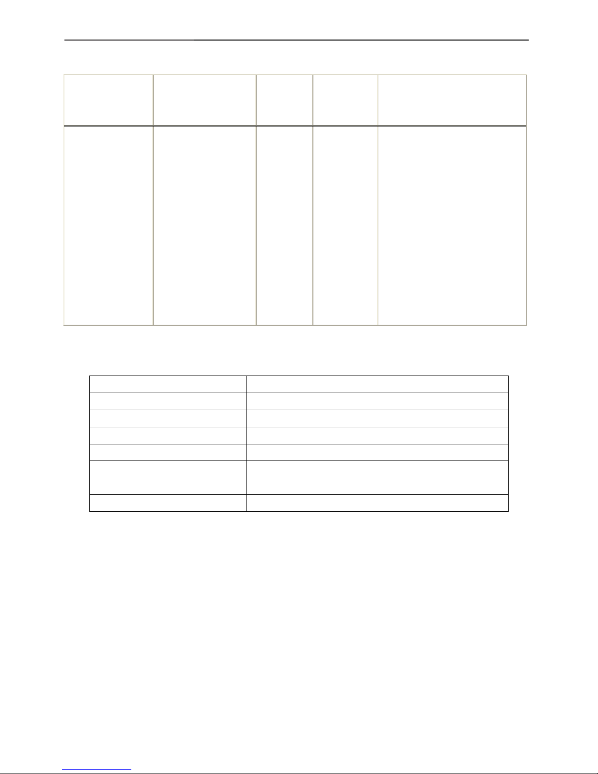
DVI Connector:
Note: Pin 1 is at the top right.
Pin Signal Assignment Pin Signal Assignment Pin Signal Assignment
1
T.M.D.S. Data 2-
9 TMDS RX1- 17 TMDS RX0-
2
T.M.D.S. Data 2+
10 TMDS RX1+ 18 TMDS RX0+
3
TMDS Ground
11
TMDS Ground 19 TMDS Ground
4 Floating 12 Floating 20 Floating
5 Floating 13 Floating 21 Floating
6
DDC Clock
14
+5V Power
22 TMDS Ground
7
DDC Data
15
Self test 23 TMDS Clock+
8
Floating
16
Hot Plug Detect
24 TMDS Clock-
20" LCD Color Monitor Dell SP2009Wc
21
4.2 Factory Preset Display Modes
Display Mode Horizontal
Frequency (kHz)
Vertical
Frequency
(Hz)
Pixel Clock
(MHz)
Sync Polarity (Horizontal/Vertical)
VESA, 720 x 400 31.5 70.0 28.3 -/+
VESA, 640 x 480 31.5 60.0 25.2 -/-
VESA, 640 x 480 37.5 75.0 31.5 -/-
VESA, 800 x 600 37.9 60.3 40.0 +/+
VESA, 800 x 600 46.9 75.0 49.5 +/+
VESA, 1024 x 768 48.4 60.0 65.0 -/-
VESA, 1024 x 768 60.0 75.0 78.8 +/+
VESA, 1152 x 864 67.5 75.0 108.0 +/+
VESA, 1280 x 1024 64.0 60.0 108.0 +/+
VESA, 1280 x 1024 80.0 75.0 135.0 +/+
VESA, 1680 x 1050 65.3 60.0 146.3 -/+
VESA, 1680 x 1050 64.7 59.9 119.0 +/-
4.3 Power Supply Requirements
A/C Line voltage range : 100 V ~ 240 V
A/C Line frequency range
: 50 ± 3Hz, 60 ± 3Hz
Current : 1.5A max at 100V; 0.8A max at 240 V
Peak surge current : < 60A peak at 240 VAC and cold starting
Leakage current : < 3.5mA
Power line surge : No advance effects (no loss of information or defect)
with a maximum of 1 half-wave missing per second
DC output Voltage
: 5VDC ± 5%; 12VDC± 5%
20" LCD Color Monitor Dell SP2009Wc
22
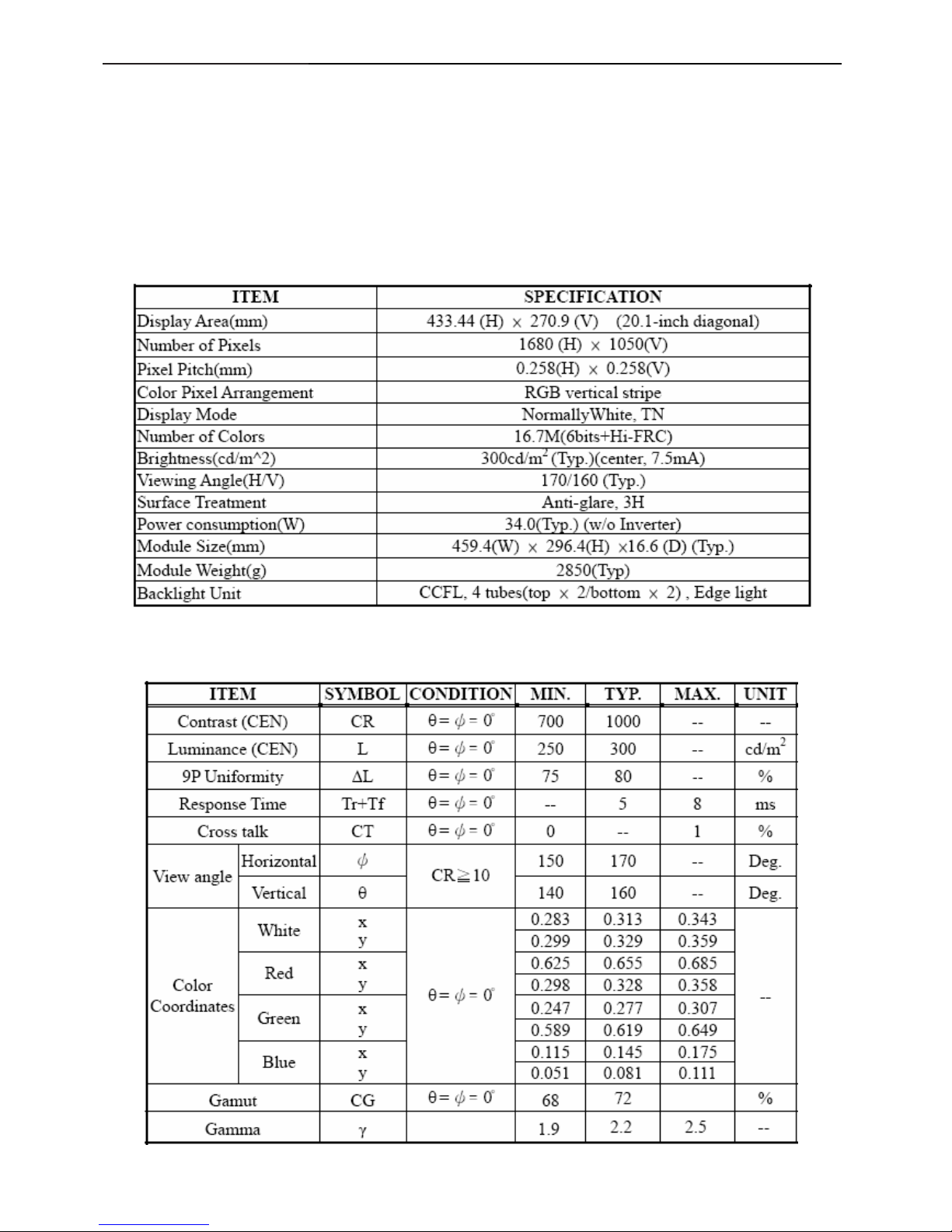
4.4 Panel Specification
CLAA201WA04 is 20.1”(51.11cm) color TFT-LCD (Thin Film Transistor Liquid Crystal Display) module composed of
LCD panel, LVDS driver ICs, control circuit and backlight(CCFL, 4 tubes). By applying 8 bit digital data
(6bits+Hi-FRC), 1680×1050, drived by 5 voltages,16.7M-color images are displayed on the 20.1” diagonal screen.
The module structure is fixed by iron frame, without the inverter for the backlight. Interface of data and control
signals is typ.
4.4.1 Display Characteristics
4.4.2 Optical Characteristics
The optical characteristics are measured under stable conditions at 25℃:
20" LCD Color Monitor Dell SP2009Wc
21
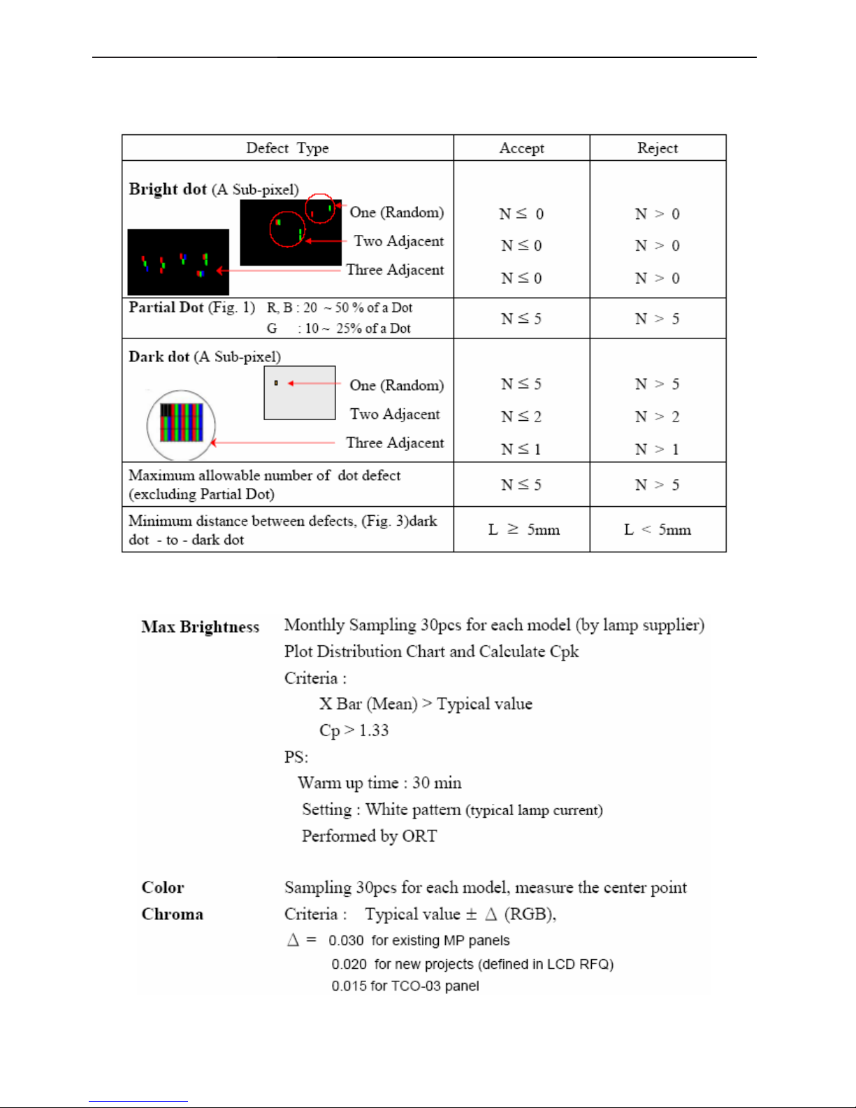
4.5 Definition of Pixel Defects
4.5.1 Spec.of Pixel Defect
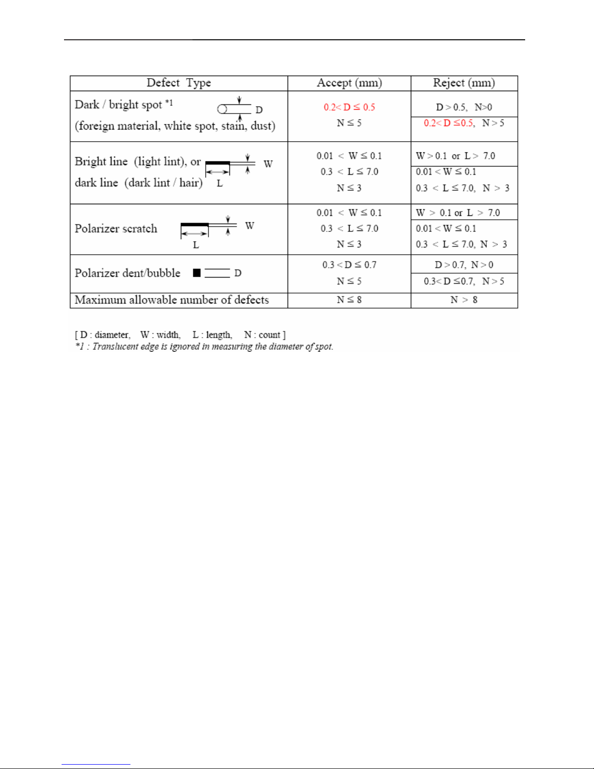
4.5.2 Optical Characteristics Failure Criteria
20" LCD Color Monitor Dell SP2009Wc
24
4.5.3 FOS Spec.
20" LCD Color Monitor Dell SP2009Wc
25
5. Block Diagram
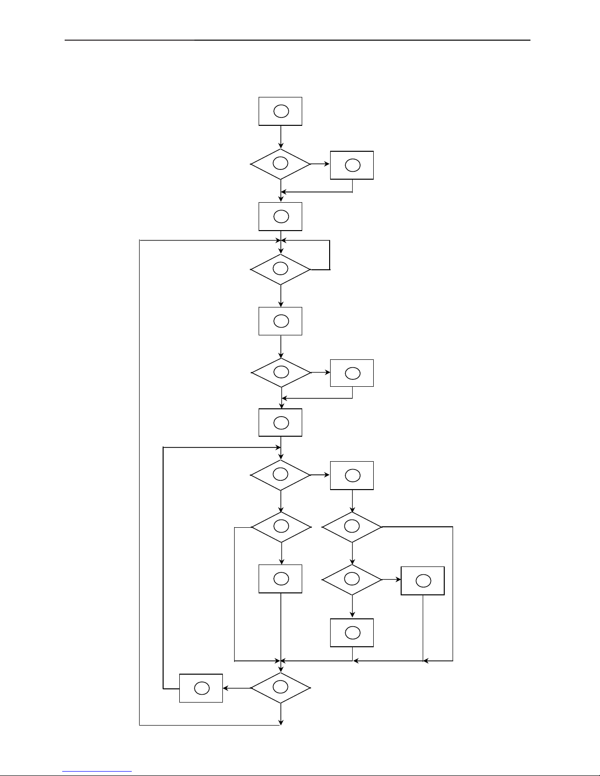
5.1 Software Flow Chart
1
2
N
Y
5
Y
N
10
Y
N
12
Y
N
7
Y
N
6
4
3
8
9
14
11
13
Y
N
15
Y
N
16
17
19
Y
N
18

20" LCD Color Monitor Dell SP2009Wc
26
1) MCU Initializes.
2) Is the EEprom blank?
3) Program the EEprom by default values.
4) Get the PWM value of brightness from EEprom.
5) Is the power key pressed?
6) Clear all global flags.
7) Are the AUTO and SELECT keys pressed?
8) Enter factory mode.
9) Save the power key status into EEprom. Turn on the LED and set it to green color. Scalar initializes.
10) In standby mode?
11) Update the lifetime of back light.
12) Check the analog port, are there any signals coming?
13) Does the scalar send out an interrupt request?
14) Wake up the scalar.
15) Are there any signals coming from analog port?
16) Display "No connection Check Signal Cable" message. And go into standby mode after the message
disappears.
17) Program the scalar to be able to show the coming mode.
18) Process the OSD display.
19) Read the keyboard. Is the power key pressed?
20" LCD Color Monitor Dell SP2009Wc
27
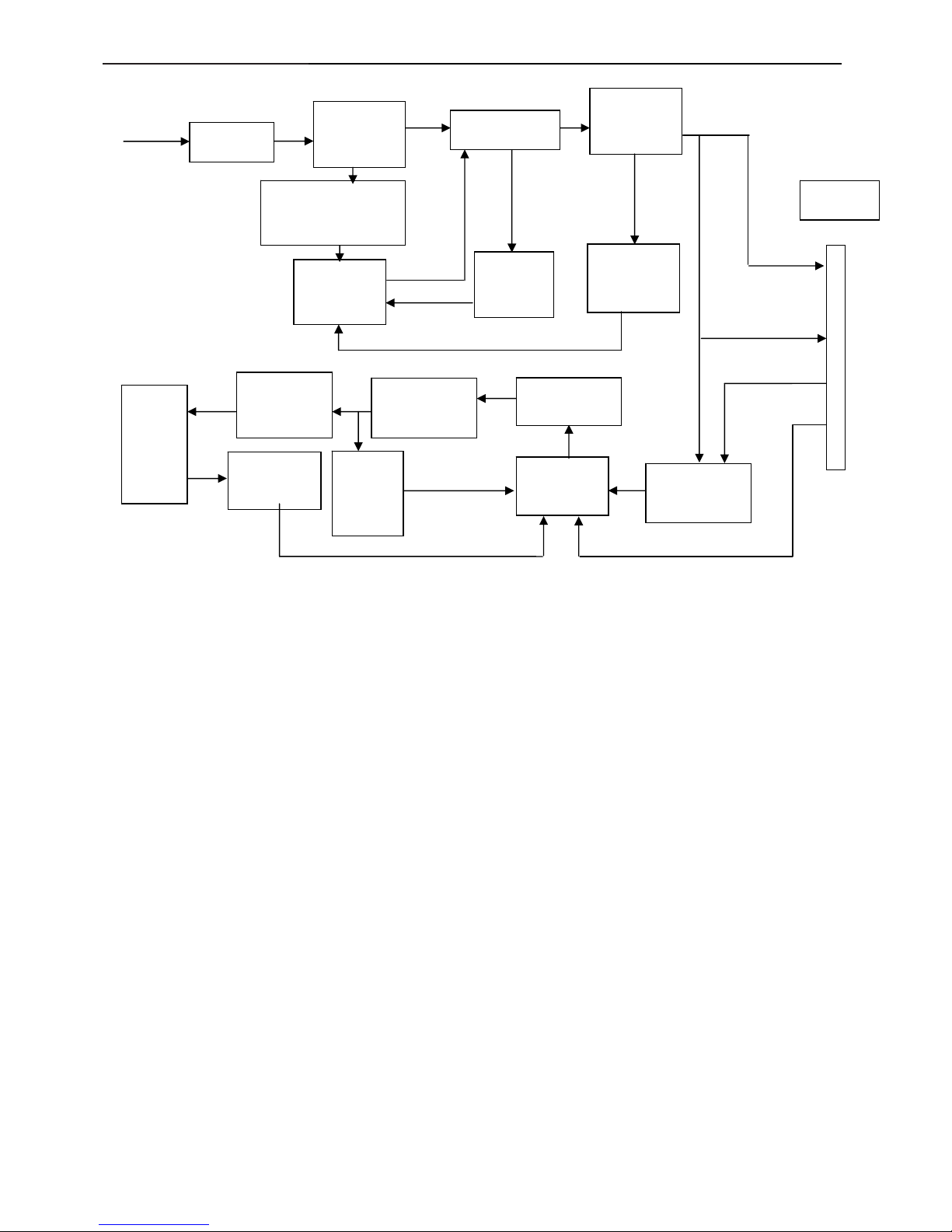
5.2 Electrical Block Diagram
5.2.1 Main Board
OSD Control Interface
(CN401)
Scalar MST9259BH-LF-165
(Include ADC, OSD)
(
U401
)
MCU
W79L659A25FL
(U402)
EEPROM
24LC16B/SNG
(
U405)
D-Sub
Connector
(CN101)
EEPROM
M24C02
(U501)
R
G
B
RXD
TXD
Digital video
signal
EPR_SDA
EPR_SCL
LCD Interface
(CN402)
H
V
DVI
Connector
(CN102)
EEPROM
M24C02
(U101)
DB15_SDA
DB15_SCL
DDC_SCL_DVI,
DDC_SDA_DVI
Crystal
24MHZ
(X402)
Crystal
14.31818MHZ
(X401)
20" LCD Color Monitor Dell SP2009Wc
28
5.2.2 Inverter and Power Board
EMI
Bridge
Rectifier
Start Circuit
R932, R904, R933
PWM
Control
IC
Over
Voltage
AC input
12V
PWM
Control IC
Feedback
Circuit
Rectify and
Output
DC Convert
Circuit
MOSFET
Over
Voltage
Protect
Lamp
ON/OFF
ON/OFF
Control
Rectifier
diodes
Feedback
Circuit
Transformer
DIM
5V
CN902
20" LCD Color Monitor Dell SP2009Wc
29
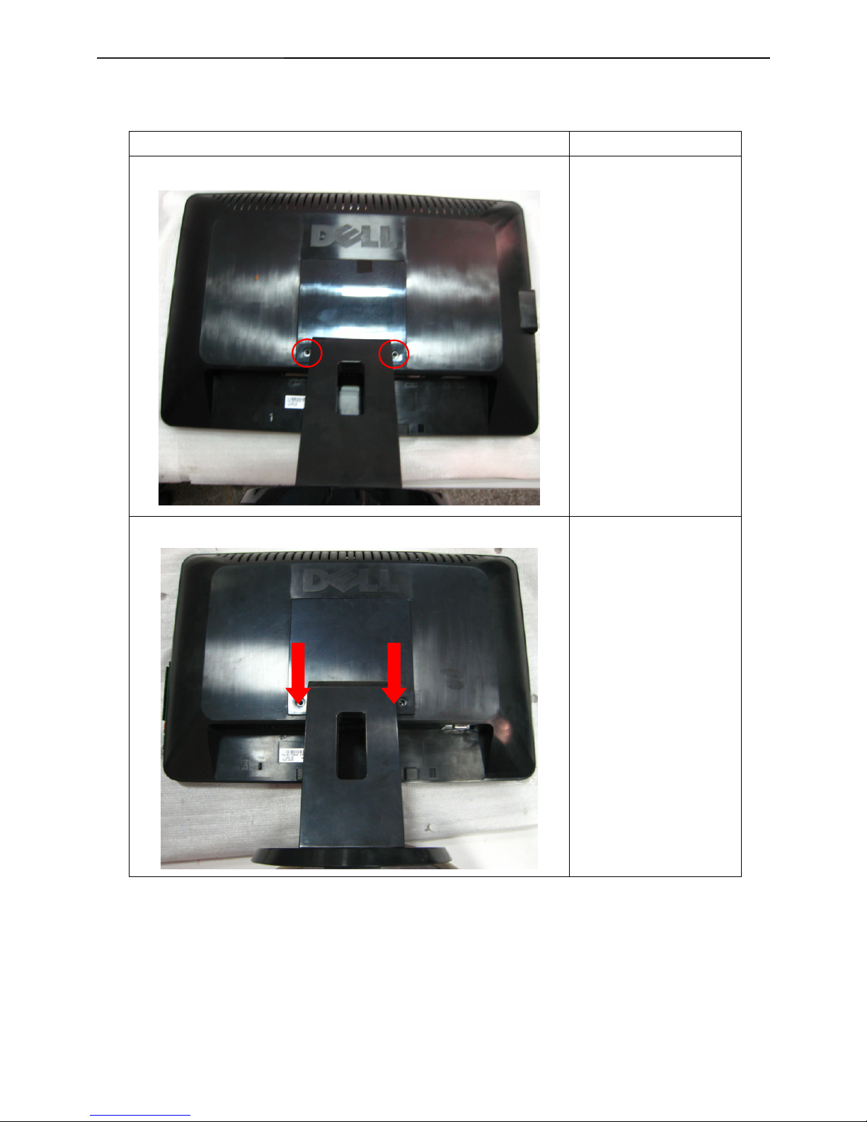
6. Mechanical Instruction
Tools: 2 Power screwdrivers(φ=5mm、L=60mm); 1 small cross screwdriver; turnbuckle driver;
Setting: Power screwdriver torque A=11 kgF. Cm; torque B=6 kgF. Cm
Fig Remark
Remove stand:
Remove the two screws
and remove the stand by
Torque A.
1. Pull out the hinge cover
follow the arrowhead
direction and remove it,
then remove the hinge.
 Loading...