

Page 1

Dell Precision Rack 7910
Owner's Manual
Regulatory Model: E31S
Regulatory Type: E31S001
Page 2

Notes, Cautions, and Warnings
NOTE: A NOTE indicates important information that helps you make better use of your computer.
CAUTION: A CAUTION indicates either potential damage to hardware or loss of data and tells you
how to avoid the problem.
WARNING: A WARNING indicates a potential for property damage, personal injury, or death.
Copyright © 2014 Dell Inc. All rights reserved. This product is protected by U.S. and international copyright and
intellectual property laws. Dell™ and the Dell logo are trademarks of Dell Inc. in the United States and/or other
jurisdictions. All other marks and names mentioned herein may be trademarks of their respective companies.
2014 - 08
Rev. A00
Page 3

Contents
1 Working on Your Computer............................................................................... 8
Turning Off Your Computer..................................................................................................................8
2 LCD panel features............................................................................................... 9
Home screen......................................................................................................................................... 9
Setup menu......................................................................................................................................... 10
View menu...........................................................................................................................................10
3 Documentation matrix.......................................................................................11
4 Hard-drive indicator codes...............................................................................12
5 Installing and removing system components............................................... 14
Safety instructions............................................................................................................................... 14
Before working inside your system.................................................................................................... 14
After working inside your system........................................................................................................14
Recommended tools...........................................................................................................................14
System Overview................................................................................................................................. 15
Front bezel (optional).......................................................................................................................... 18
Removing the front bezel..............................................................................................................18
Installing the front bezel................................................................................................................19
Removing the system cover................................................................................................................19
Installing the system cover.................................................................................................................20
Inside the system.................................................................................................................................21
Cooling shroud....................................................................................................................................22
Removing the cooling shroud...................................................................................................... 23
Installing the cooling shroud........................................................................................................ 23
System memory.................................................................................................................................. 24
General memory module installation guidelines...............................................................................26
Sample memory configurations.........................................................................................................26
Removing memory modules..............................................................................................................29
Installing memory modules.................................................................................................................31
Hard drives...........................................................................................................................................33
Removing a 2.5 inch hard-drive blank............................................................................................... 33
Installing a 2.5 inch hard-drive blank................................................................................................. 34
Removing Hard Drive..........................................................................................................................34
Installing Hard Drive............................................................................................................................35
Removing a hard drive from a hard-drive carrier.............................................................................. 36
Page 4

Installing a hard drive into a hard-drive carrier..................................................................................37
Optical drive (optional)....................................................................................................................... 38
Removing the optical drive...........................................................................................................38
Installing the optical drive.............................................................................................................39
Cooling fans........................................................................................................................................40
Removing a cooling fan......................................................................................................................40
Installing a cooling fan........................................................................................................................ 41
Removing the cooling-fan assembly................................................................................................. 42
Installing the cooling-fan assembly................................................................................................... 44
Internal USB memory key (optional).................................................................................................. 44
Replacing the internal USB key...........................................................................................................45
PCIe card holder................................................................................................................................. 45
Removing the PCIe card holder................................................................................................... 45
Installing the PCIe card holder......................................................................................................47
Opening and closing the PCIe card holder latch.........................................................................47
Cable retention bracket......................................................................................................................48
Removing the cable retention bracket.........................................................................................48
Installing the cable retention bracket...........................................................................................49
Expansion cards and expansion-card risers...................................................................................... 50
Expansion card installation guidelines......................................................................................... 50
Removing an expansion card from expansion-card riser 2 or 3.................................................50
Installing an expansion card into the expansion-card riser 2 or 3..............................................52
Removing an expansion card from the expansion-card riser 1.................................................. 53
Installing an expansion card into the expansion-card riser 1......................................................54
Removing the riser 1 blank............................................................................................................55
Installing the riser 1 blank..............................................................................................................56
Removing expansion-card risers..................................................................................................56
Installing expansion-card risers....................................................................................................62
GPU card installation guidelines...................................................................................................63
Installing a GPU card.....................................................................................................................63
Removing a GPU card...................................................................................................................64
SD vFlash media card..........................................................................................................................65
Replacing an SD vFlash media card..............................................................................................65
Internal dual SD module.....................................................................................................................66
Removing an internal SD card......................................................................................................66
Installing an internal SD card........................................................................................................ 67
Removing the internal dual SD module ...................................................................................... 67
Installing the internal dual SD module ........................................................................................ 69
Integrated storage controller card..................................................................................................... 70
Removing the integrated storage controller card....................................................................... 70
Installing the integrated storage controller card..........................................................................71
Network daughter card.......................................................................................................................72
Page 5

Removing the network daughter card .........................................................................................72
Installing the network daughter card........................................................................................... 74
Processors........................................................................................................................................... 74
Removing a processor...................................................................................................................75
Installing a processor.................................................................................................................... 79
Power supply units.............................................................................................................................. 81
Hot Spare feature................................................................................................................................ 81
Removing the power supply unit blank............................................................................................. 82
Installing the power supply unit blank............................................................................................... 82
Removing an AC power supply unit...................................................................................................82
Installing an AC power supply unit.....................................................................................................84
System battery.....................................................................................................................................85
Replacing the system battery....................................................................................................... 85
Hard-drive backplane......................................................................................................................... 86
Removing the hard-drive backplane .................................................................................................87
Installing the hard-drive backplane ...................................................................................................88
Control panel assembly......................................................................................................................89
Removing the control panel ........................................................................................................89
Installing the control panel .......................................................................................................... 91
System board.......................................................................................................................................91
Removing the system board......................................................................................................... 91
Installing the system board...........................................................................................................94
Entering the system service tag using System Setup...................................................................95
Restoring the service tag using Easy Restore...............................................................................95
Updating the BIOS version............................................................................................................96
Re-enabling the TPM for TXT users............................................................................................. 96
6 Troubleshooting your system.......................................................................... 97
Safety first—for you and your system.................................................................................................97
Troubleshooting system startup failure..............................................................................................97
Troubleshooting external connections..............................................................................................97
Troubleshooting the video subsystem...............................................................................................97
Troubleshooting a USB device........................................................................................................... 97
Troubleshooting iDRAC Direct (USB XML configuration)................................................................. 98
Troubleshooting iDRAC Direct (laptop connection).........................................................................98
Troubleshooting a serial I/O device...................................................................................................99
Troubleshooting a NIC....................................................................................................................... 99
Troubleshooting a wet system...........................................................................................................99
Troubleshooting a damaged system............................................................................................... 100
Troubleshooting the system battery................................................................................................100
Troubleshooting power supply units................................................................................................101
Power source problems.............................................................................................................. 101
Page 6

Power supply unit problems....................................................................................................... 101
Troubleshooting cooling problems................................................................................................. 102
Troubleshooting cooling fans.......................................................................................................... 102
Troubleshooting system memory....................................................................................................103
Troubleshooting an internal USB key...............................................................................................104
Troubleshooting an SD card.............................................................................................................104
Troubleshooting an optical drive..................................................................................................... 105
Troubleshooting a hard drive........................................................................................................... 105
Troubleshooting a storage controller..............................................................................................106
Troubleshooting expansion cards....................................................................................................106
Troubleshooting processors.............................................................................................................107
Error Messages.................................................................................................................................. 107
Errors That Halt the System CompletelyErrors That Soft Halts the SystemError That do
not Halt the system..................................................................................................................... 107
System messages..............................................................................................................................108
Warning messages...................................................................................................................... 108
Diagnostic messages.................................................................................................................. 108
Alert messages............................................................................................................................ 108
7 Using system diagnostics................................................................................ 110
Dell Embedded System Diagnostics.................................................................................................110
When to use the Embedded System Diagnostics...................................................................... 110
Running the Embedded System Diagnostics from Boot Manager............................................110
Running the Embedded System Diagnostics from the Dell Lifecycle Controller.....................110
System diagnostic controls..........................................................................................................111
8 Jumpers and connectors................................................................................ 112
System board jumper settings...........................................................................................................112
System board connectors................................................................................................................. 113
Disabling a forgotten password........................................................................................................ 115
9 Specifications.................................................................................................... 116
10 System Setup...................................................................................................122
Boot Menu......................................................................................................................................... 122
Timing Key Sequences......................................................................................................................122
Dell Diagnostics.................................................................................................................................123
About System Setup.......................................................................................................................... 123
Entering System Setup................................................................................................................ 123
System Setup Main Menu............................................................................................................123
System BIOS screen.................................................................................................................... 124
System Information screen details............................................................................................. 124
Page 7

Memory Settings screen details..................................................................................................125
Processor Settings screen details............................................................................................... 126
SATA Settings screen details....................................................................................................... 128
Boot Settings screen details........................................................................................................130
Integrated Devices screen details............................................................................................... 131
Serial Communication screen details.........................................................................................133
System Profile Settings screen details........................................................................................ 133
System Security settings screen details......................................................................................135
Miscellaneous Settings screen details........................................................................................ 136
11 NIC indicator codes........................................................................................139
12 Power indicator codes.................................................................................. 140
13 Contacting Dell...............................................................................................142
Contacting Dell................................................................................................................................. 142
Quick Resource Locator (QRL).........................................................................................................142
Page 8
Working on Your Computer
Turning Off Your Computer
CAUTION: To avoid losing data, save and close all open files and exit all open programs before
you turn off your computer.
1. Shut down the operating system:
• In Windows 8:
– Using a touch-enabled device:
a. Swipe in from the right edge of the screen, opening the Charms menu and select
Settings.
b. Select the and then select Shut down
– Using a mouse:
a. Point to upper-right corner of the screen and click Settings.
b. Click the and select Shut down.
• In Windows 7:
1
1. Click Start .
2. Click Shut Down.
or
1. Click Start .
2. Click the arrow in the lower-right corner of the Start menu as shown below, and then click
Shut Down..
2. Ensure that the computer and all attached devices are turned off. If your computer and attached
devices did not automatically turn off when you shut down your operating system, press and hold
the power button for about 6 seconds to turn them off.
8
Page 9
2
LCD panel features
NOTE: The LCD panel is present only on Precision Rack 7910
The LCD panel of your system provides system information and status and error messages to indicate if
the system is operating correctly or if the system needs attention. For more information on error
messages, see the Dell Event and Error Messages Reference Guide at dell.com/esmmanuals.
• The LCD backlight lights blue during normal operating conditions and lights amber to indicate an
error condition.
• The LCD backlight is off when the system is in standby mode and can be turned on by pressing either
the Select, Left, or Right button on the LCD panel.
• The LCD backlight remains off if LCD messaging is turned off through the iDRAC utility, the LCD
panel, or other tools.
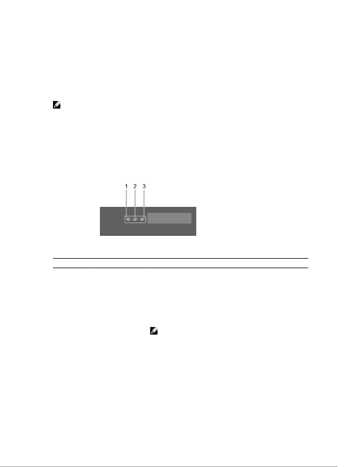
Figure 1. LCD panel features
Item Button Description
1 Left Moves the cursor back in one-step increments.
2 Select Selects the menu item highlighted by the cursor.
3 Right Moves the cursor forward in one-step increments.
During message scrolling:
• Press and hold the button to increase scrolling speed.
• Release the button to stop.
NOTE: The display will stop scrolling when the button is
released. After 45 seconds of inactivity the display will start
scrolling.
Home screen
The Home screen displays user-configurable information about the system. This screen is displayed
during normal system operation when there are no status messages or errors. When the system is in
standby mode, the LCD backlight turns off after five minutes of inactivity if there are no error messages.
Press one of the three navigation buttons (Select, Left, or Right) to view the Home screen.
9
Page 10

To navigate to the Home screen from another menu, continue to select the up arrow until the Home
icon is displayed, and then select the Home icon.
From the Home screen, press the Select button to enter the main menu.
Setup menu
NOTE: When you select an option in the Setup menu, you must confirm the option before
proceeding to the next action.
Option Description
iDRAC Select DHCP or Static IP to configure the network mode. If Static IP is selected,
the available fields are IP, Subnet (Sub), and Gateway (Gtw). Select Setup DNS to
enable DNS and to view domain addresses. Two separate DNS entries are available.
Set error Select SEL to display LCD error messages in a format that matches the IPMI
description in the SEL. This is useful when trying to match an LCD message with an
SEL entry.
Select Simple to display LCD error messages in a simplified user-friendly
description. For more information on error messages, see the Dell Event and Error
Messages Reference Guide at dell.com/esmmanuals.
Set home Select the default information to be displayed on the LCD Home screen. See View
menu to see the options and option items that can be set as the default on the
Home screen.
View menu
NOTE: When you select an option in the View menu, you must confirm the option before
proceeding to the next action.
Option Description
iDRAC IP Displays the IPv4 or IPv6 addresses for iDRAC8. Addresses include DNS (Primary
and Secondary), Gateway, IP, and Subnet (IPv6 does not have Subnet).
MAC Displays the MAC addresses for iDRAC, iSCSI, or Network devices.
Name Displays the name of the Host, Model, or User String for the system.
Number Displays the Asset tag or the Service tag for the system.
Power Displays the power output of the system in BTU/hr or Watts. The display format can
be configured in the Set home submenu of the Setup menu.
Temperature Displays the temperature of the system in Celsius or Fahrenheit. The display format
can be configured in the Set home submenu of the Setup menu.
10
Page 11

3
Documentation matrix
The documentation matrix provides information on documents that you can refer to for setting up and
managing your system.
To... Refer to...
Install your system into a rack Rack documentation included with your rack
solution
Set up your system and know the system technical
specifications
Install the operating system Operating system documentation at dell.com/
Get an overview of the Dell Systems Management
offerings
Configure and log in to iDRAC, set up managed
and management system, know the iDRAC
features and troubleshoot using iDRAC
Know about the RACADM subcommands and
supported RACADM interfaces
Launch, enable and disable Lifecycle Controller,
know the features, use and troubleshoot Lifecycle
Controller
Use Lifecycle Controller Remote Services Dell Lifecycle Controller Remote Services Quick
Set up, use, and troubleshoot OpenManage Server
Administrator
Install, use and troubleshoot OpenManage
Essentials
Getting Started With Your System that shipped with
your system or see dell.com/poweredgemanuals
operatingsystemmanuals
Dell OpenManage Systems Management Overview
Guide at dell.com/openmanagemanuals
Integrated Dell Remote Access Controller User's
Guide at dell.com/esmmanuals
RACADM Command Line Reference Guide for
iDRAC and CMC at dell.com/esmmanuals
Dell Lifecycle Controller User’s Guide at dell.com/
esmmanuals
Start Guide at dell.com/esmmanuals
Dell OpenManage Server Administrator User’s
Guide at dell.com/openmanagemanuals
Dell OpenManage Essentials User’s Guide at
dell.com/openmanagemanuals
Know the features of the storage controller cards,
deploy the cards, and manage the storage
subsystem
Check the event and error messages generated by
the system firmware and agents that monitor
system components
Storage controller documentation at dell.com/
storagecontrollermanuals
Dell Event and Error Messages Reference Guide at
dell.com/esmmanuals
11
Page 12
Hard-drive indicator codes
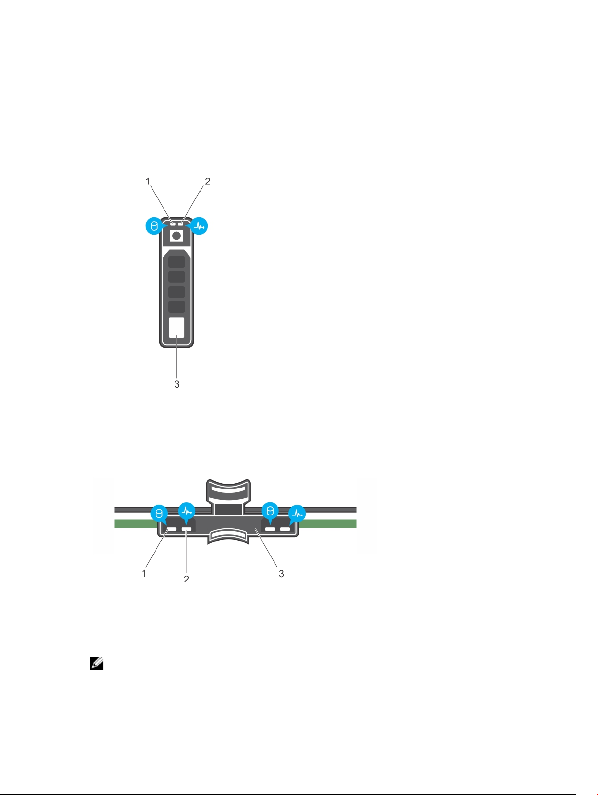
Figure 2. Hard-drive indicators
4
1. hard-drive activity indicator 2. hard-drive status indicator
3. hard drive
Figure 3. Hard-drive indicators on the hard-drive tray backplane
1. hard-drive activity indicator 2. hard-drive status indicator
3. hard-drive backplane on hard-drive tray
NOTE: If the hard drive is in Advanced Host Controller Interface (AHCI) mode, the status indicator
(on the right side) does not function and remains off.
12
Page 13

Drive-status indicator pattern (RAID only) Condition
Blinks green two times per second Identifying drive or preparing for removal.
Off Drive ready for insertion or removal.
NOTE: The drive status indicator remains off until
all hard drives are initialized after the system is
turned on. Drives are not ready for insertion or
removal during this time.
Blinks green, amber, and turns off Predicted drive failure
Blinks amber four times per second Drive failed
Blinks green slowly Drive rebuilding
Steady green Drive online
Blinks green three seconds, amber three
seconds, and turns off six seconds
Rebuild aborted
13
Page 14
Installing and removing system components
Safety instructions
WARNING: Whenever you need to lift the system, get others to assist you. To avoid injury, do not
attempt to lift the system by yourself.
WARNING: Opening or removing the system cover when the system is on may expose you to a
risk of electric shock.
CAUTION: Do not operate the system without the cover for a duration exceeding five minutes.
CAUTION: Many repairs may only be done by a certified service technician. You should only
perform troubleshooting and simple repairs as authorized in your product documentation, or as
directed by the online or telephone service and support team. Damage due to servicing that is
not authorized by Dell is not covered by your warranty. Read and follow the safety instructions
that came with the product.
NOTE: It is recommended that you always use a static mat and static strap while working on
components inside the system.
5
NOTE: To ensure proper operation and cooling, all bays in the system must be populated at all
times with either a module or with a blank.
Before working inside your system
1. Turn off the system, including any attached peripherals.
2. Disconnect the system from the electrical outlet and disconnect the peripherals.
3. Remove the system cover.
After working inside your system
1. Install the system cover.
2. Reconnect the system to its electrical outlet.
3. Turn the system on, including any attached peripherals.
Recommended tools
You need the following tools to perform the removal and installation procedures:
• Key to the bezel lock. This is only required when you have a bezel.
14
Page 15
• #2 Phillips screwdriver
For how-to videos, documentation, and troubleshooting solutions, scan this QR code, or click here:
http://www.Dell.com/QRL/Workstation/R7910
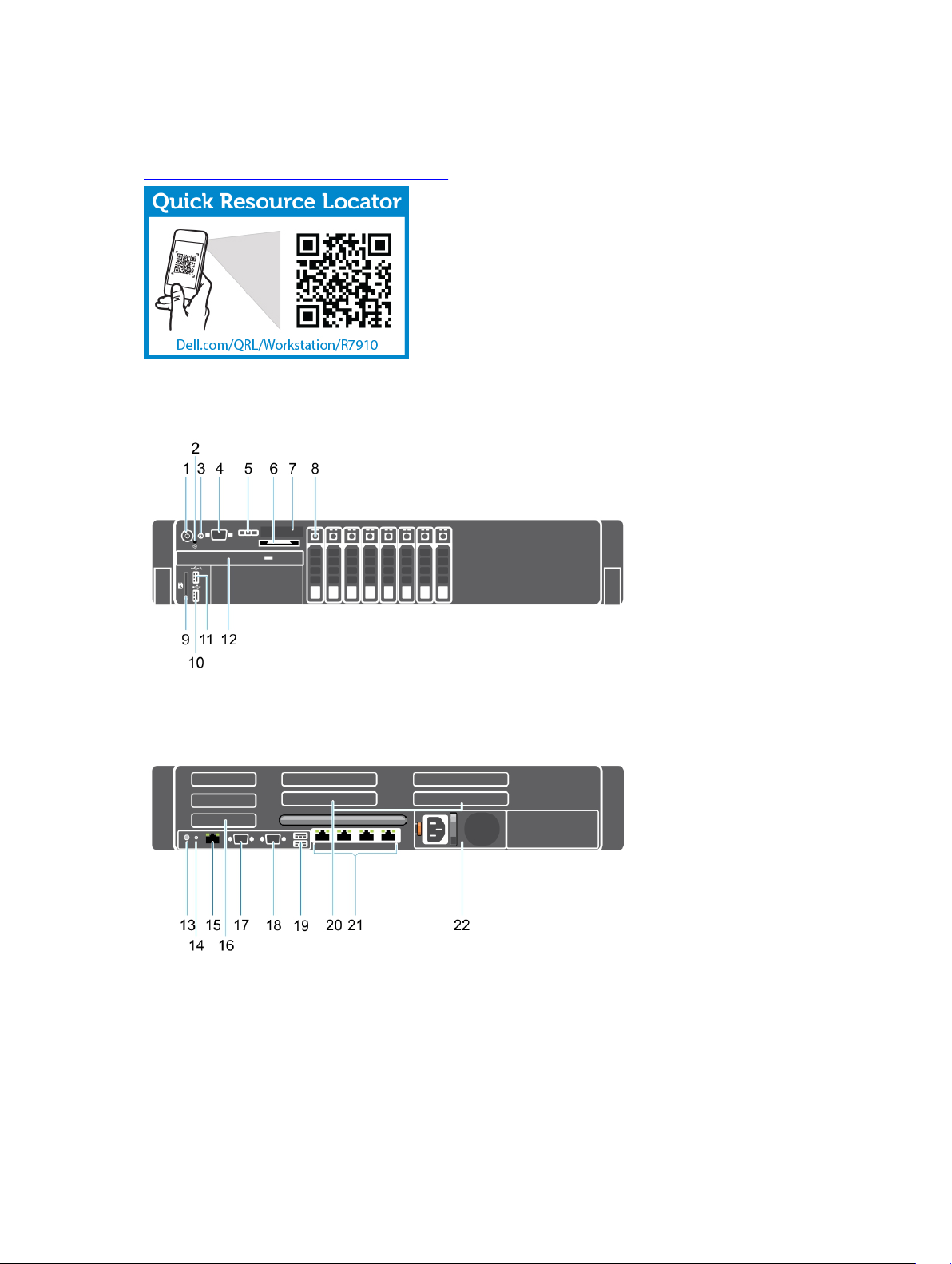
System Overview
Figure 4. Front and Back View
15
Page 16
Item Indicator, Button, or
Connector
Icon Description
1 Power-on indicator,
power button
2 NMI button
3 System identification
button
The power-on indicator lights when the system
power is on. The power button controls the power
supply output to the system.
NOTE: On ACPI-compliant operating systems,
turning off the system using the power button
causes the system to perform a graceful
shutdown before power to the system is
turned off.
Used to troubleshoot software and device driver
errors when running certain operating systems.
This button can be pressed using the end of a
paper clip.
Use this button only if directed to do so by
qualified support personnel or by the operating
system documentation.
The identification buttons on the front and back
panels can be used to locate a particular system
within a rack. When one of these buttons is
pressed, the LCD panel on the front and the
system status indicator on the back flashes until
one of the buttons is pressed again.
Press to toggle the system ID on and off.
If the system stops responding during POST, press
and hold the system ID button for more than five
seconds to enter BIOS progress mode.
To reset iDRAC (if not disabled in F2 iDRAC setup)
press and hold the button for more than 15
seconds.
4 Video connector Allows you to connect a VGA display to the
system.
5 LCD menu buttons Allow you to navigate the control panel LCD
menu.
6 Information tag A slide-out label panel which allows you to record
system information such as Service Tag, NIC, MAC
address and so on as per your need.
7 LCD panel Displays system ID, status information, and system
error messages. The LCD lights blue during normal
system operation. The LCD lights amber when the
system needs attention, and the LCD panel
displays an error code followed by descriptive text.
16
Page 17
Item Indicator, Button, or
Connector
8 Hard drives Up to eight 2.5 inch drives.
9 vFlash media card slot Allows you to insert a vFlash media card.
10 USB connector Allows you to connect USB devices to the system.
11 USB management port/
iDRAC Direct
12 Optical drive (optional) One optional SATA DVD-ROM drive or DVD+/-RW
Icon Description
NOTE: If the system is connected to a power
source and an error is detected, the LCD lights
amber regardless of whether the system is
turned on or off.
The ports are USB 2.0-compliant.
Allows you to connect USB devices to the system
or provides access to the iDRAC Direct features.
For more information, see the Integrated Dell
Remote Access Controller User’s Guide at
dell.com/esmmanuals. The USB management port
is USB 2.0-compliant.
drive.
13 System identification
button
14 System identification
connector
15 iDRAC8 Enterprise port Dedicated management port.
The identification buttons on the front and back
panels can be used to locate a particular system
within a rack.
Precision Rack
7910
Press to toggle the system ID on and off.
If the system stops responding during POST, press
and hold the system ID button for more than five
seconds to enter BIOS progress mode.
To reset iDRAC (if not disabled in F2 iDRAC setup)
press and hold the button for more than 15
seconds.
Connects the optional system status indicator
assembly through the optional cable management
arm.
When one of these buttons
is pressed, the LCD panel on
the front and the system
status indicator on the back
flashes until one of the
buttons is pressed again.
16 Half-height PCIe
expansion-card slot (3)
Allows you to connect up to three half-height PCI
Express expansion cards.
17
Page 18

Item Indicator, Button, or
Connector
17 Serial connector Allows you to connect a serial device to the
18 Video connector Allows you to connect a VGA display to the
19 USB connector (2) Allows you to connect USB devices to the system.
Icon Description
system.
system.
The ports are USB 2.0-compliant.
20 Full-height PCIe
expansion card slot (4)
21 Ethernet connector (4) Four integrated 10/100/1000 Mbps NIC
22 Power supply unit
Allows you to connect up to four single wall or
two double wide PCI Express expansion cards.
connectors
or
Four integrated connectors that include:
• Two 10/100/1000 Mbps NIC connectors
• Two 100 Mbps/1 Gbps/10 Gbps NIC
connectors
AC 1100 W
Front bezel (optional)
Removing the front bezel
1. Unlock the bezel lock at the left end of the bezel.
2. Lift the release latch next to the bezel lock.
3. Pull the left end of the bezel, unhook the right end and remove the bezel.
18
Page 19
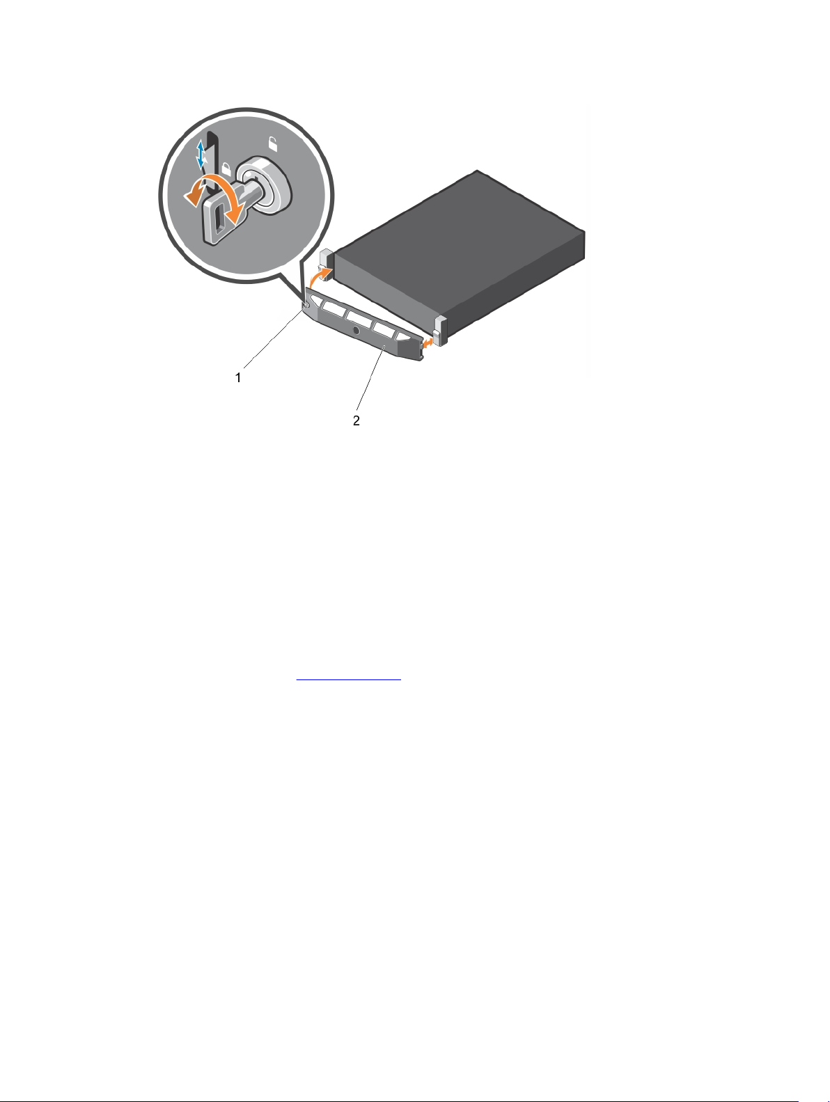
Figure 5. Removing and installing the front bezel
1. bezel lock 2. front bezel
Installing the front bezel
1. Hook the right end of the bezel onto the chassis.
2. Fit the free end of the bezel onto the system.
3. Secure the bezel with the keylock.
Removing the system cover
1. Ensure that you read the Safety instructions.
2. Turn off the system, including any attached peripherals.
3. Disconnect the system from the electrical outlet and peripherals.
4. Rotate the latch release lock counter clockwise to the unlocked position.
5. Lift the latch and rotate the latch toward the back of the system.
19
Page 20
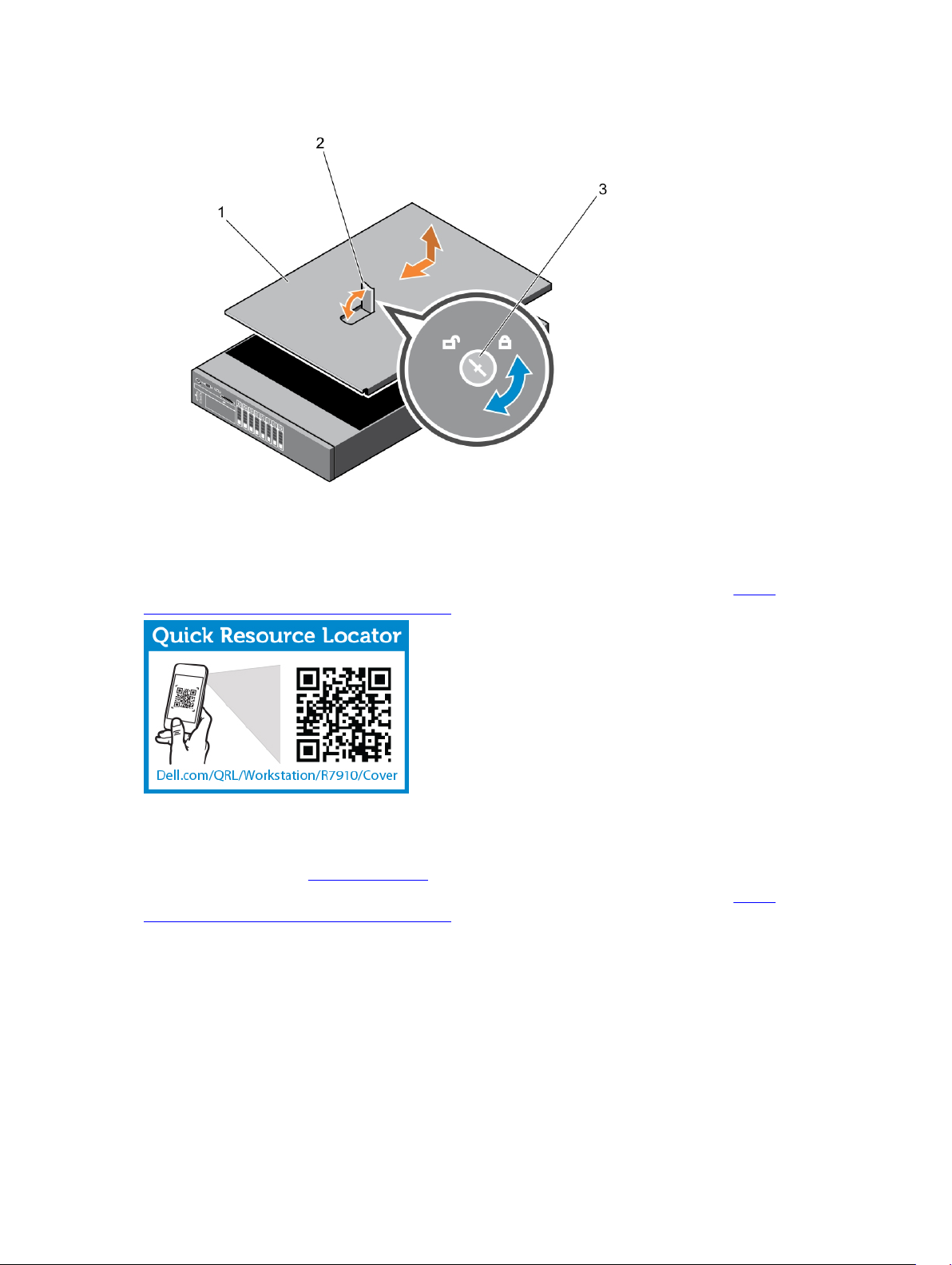
6. Hold the cover on both sides, and lift the cover away from the system.
1. system cover
2. latch
3. latch release lock
To see a video on removing and installing System Cover, scan this QR code, or click here: http://
www.Dell.com/QRL/Workstation/R7910/Cover
Installing the system cover
Ensure that you read the Safety instructions.
To see a video on removing and installing System Cover, scan this QR code, or click here: http://
www.Dell.com/QRL/Workstation/R7910/Cover
20
Page 21
1. Align the slots of the system cover with the tabs on the chassis.
2. Press the cover release latch, and push the cover toward the front of the chassis until the latch locks
into place.
3. Turn the latch release lock clockwise to the locked position.
4. Install the optional bezel.
5. Reconnect the system to its electrical outlet and turn the system on, including any attached
peripherals.
Inside the system
CAUTION: Many repairs may only be done by a certified service technician. You should only
perform troubleshooting and simple repairs as authorized in your product documentation, or as
directed by the online or telephone service and support team. Damage due to servicing that is
not authorized by Dell is not covered by your warranty. Read and follow the safety instructions
that came with the product.
21
Page 22
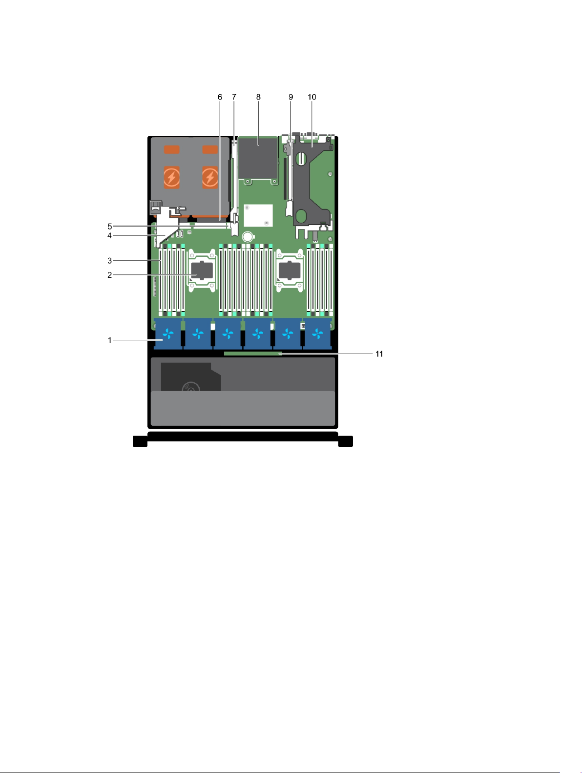
Figure 6. Inside the system—Precision Rack 7910
1. cooling-fan (6)
2. processor (2)
3. DIMM (24)
4. PCIe card holder
5. internal USB port
6. power supply unit (2)
7. expansion-card riser (3)
8. network daughter card
9. expansion-card riser (2)
10. expansion-card riser (1)
11. hard-drive backplane
Cooling shroud
22
Page 23

Removing the cooling shroud
CAUTION: Many repairs may only be done by a certified service technician. You should only
perform troubleshooting and simple repairs as authorized in your product documentation, or as
directed by the online or telephone service and support team. Damage due to servicing that is
not authorized by Dell is not covered by your warranty. Read and follow the safety instructions
that came with the product.
1. Ensure that you read the Safety instructions.
2. Follow the procedure listed in Before working inside your system.
3. If installed, remove the full-length PCIe cards.
CAUTION: Never operate your system with the cooling shroud removed. The system may get
overheated quickly, resulting in shutdown of the system and loss of data.
Hold the shroud and lift it away from the system.
Figure 7. Removing and installing the cooling shroud
1. cooling shroud 2. touch point (2)
1. Replace the cooling shroud. See Installing the cooling shroud
2. Follow the procedure listed in After working inside your system.
Installing the cooling shroud
CAUTION: Many repairs may only be done by a certified service technician. You should only
perform troubleshooting and simple repairs as authorized in your product documentation, or as
directed by the online or telephone service and support team. Damage due to servicing that is
not authorized by Dell is not covered by your warranty. Read and follow the safety instructions
that came with the product.
1. Ensure that you read the Safety instructions.
2. Align the tabs on the cooling shroud with the securing slots on the chassis.
3. Lower the cooling shroud into the chassis until it is firmly seated.
23
Page 24

4. Follow the procedure listed in After working inside your system.
System memory
Your system supports DDR4 registered DIMMs (RDIMMs), and load reduced DIMMs (LRDIMMs).
NOTE: MT/s indicates DIMM speed in MegaTransfers per second.
Memory bus operating frequency can be 1866 MT/s, or 2133 MT/s depending on the following factors:
• DIMM type (RDIMM or LRDIMM)
• Number of DIMMs populated per channel
• System profile selected (for example, Performance Optimized, Custom, or Dense Configuration
Optimized)
• Maximum supported DIMM frequency of the processors
The system contains 24 memory sockets split into two sets of 12 sockets, one set per processor. Each 12socket set is organized into four channels. In each channel, the release levers of the first socket are
marked white, the second socket black, and the third socket green.
NOTE: DIMMs in sockets A1 to A12 are assigned to processor 1 and DIMMs in sockets B1 to B12 are
assigned to processor 2.
24
Page 25
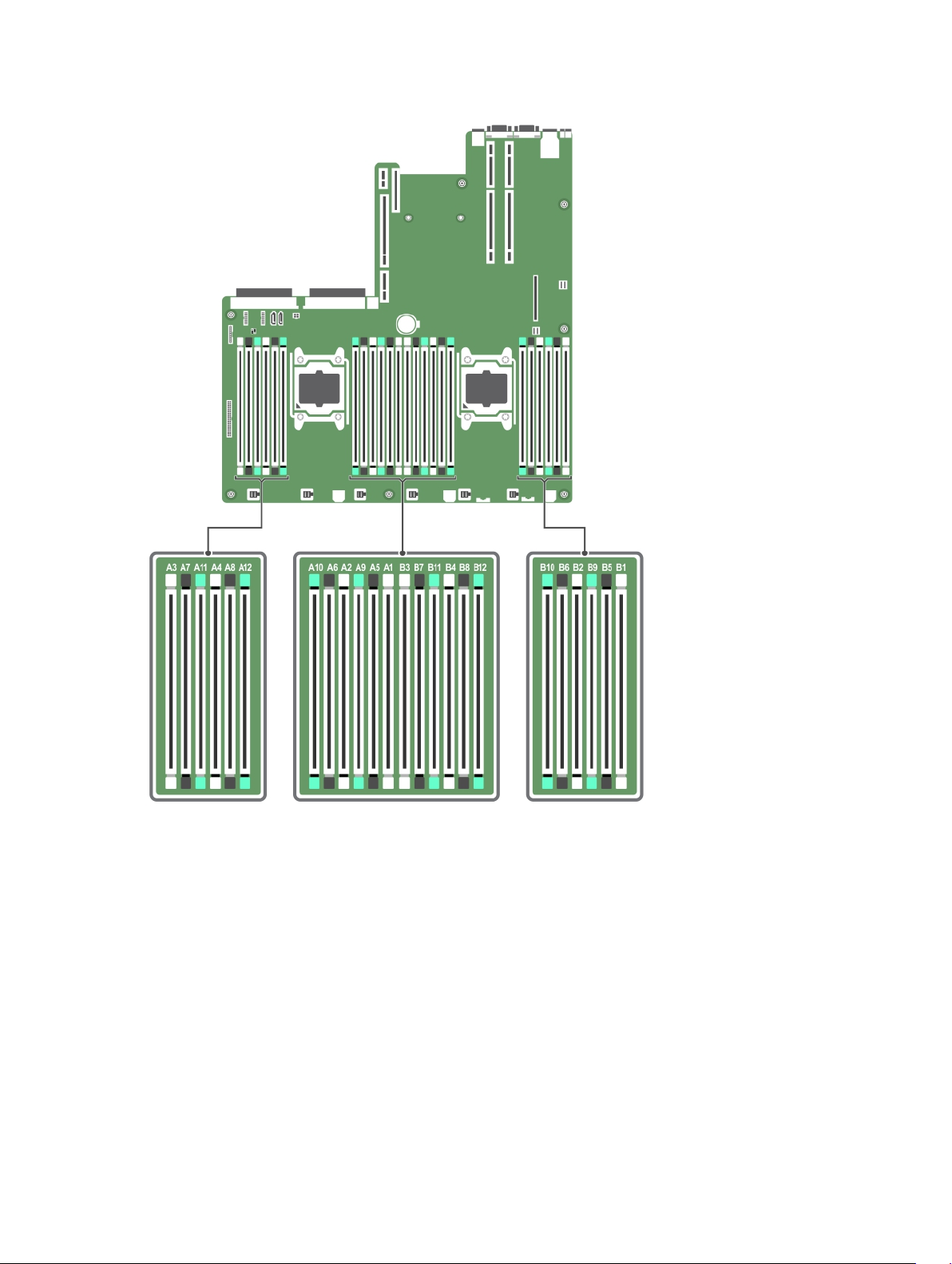
Memory channels are organized as follows:
Processor 1 channel 0: slots A1, A5, and A9
channel 1: slots A2, A6, and A10
channel 2: slots A3, A7, and A11
channel 3: slots A4, A8, and A12
Processor 2 channel 0: slots B1, B5, and B9
channel 1: slots B2, B6, and B10
channel 2: slots B3, B7, and B11
channel 3: slots B4, B8, and B12
25
Page 26

The following table shows the memory populations and operating frequencies for the supported
configurations.
DIMM Type DIMMs Populated/
Channel
RDIMM 1 2133, 1866, 1600, 1333 Dual rank or single rank
2 2133, 1866, 1600, 1333 Dual rank or single rank
3 1866, 1600, 1333 Dual rank or single rank
LRDIMM 1 2133, 1866, 1600, 1333 Quad rank
2 2133, 1866, 1600, 1333 Quad rank
3 1866, 1600, 1333 Quad rank
Operating Frequency (in
MT/s)
1.2 V
Maximum DIMM Rank/Channel
General memory module installation guidelines
This system supports Flexible Memory Configuration, enabling the system to be configured and run in
any valid chipset architectural configuration. The following are the recommended guidelines for installing
memory modules:
• RDIMMs and LRDIMMs must not be mixed.
• x4 and x8 DRAM based DIMMs can be mixed.
• Up to three dual- or single-rank RDIMMs can be populated per channel.
• Up to three LRDIMMs can be populated per channel regardless of rank count.
• Populate DIMM sockets only if a processor is installed. For single-processor systems, sockets A1 to
A12 are available. For dual-processor systems, sockets A1 to A12 and sockets B1 to B12 are available.
• Populate all sockets with white release tabs first, then black, and then green.
• Populate the sockets by highest rank count in the following order — first in sockets with white release
levers, then black, and then green. For example, if you want to mix single-rank and dual-rank DIMMs,
populate dual-rank DIMMs in the sockets with white release tabs and single-rank DIMMs in the
sockets with black release tabs.
• When mixing memory modules with different capacities, populate the sockets with memory modules
with highest capacity first. For example, if you want to mix 4 GB and 8 GB DIMMs, populate 8 GB
DIMMs in the sockets with white release tabs and 4 GB DIMMs in the sockets with black release tabs.
• In a dual-processor configuration, the memory configuration for each processor should be identical.
For example, if you populate socket A1 for processor 1, then populate socket B1 for processor 2, and
so on.
• Memory modules of different capacities can be mixed provided other memory population rules are
followed (for example, 4 GB and 8 GB memory modules can be mixed).
• Mixing of more than two DIMM capacities in a system is not supported.
• Populate four DIMMs per processor (one DIMM per channel) at a time to maximize performance.
Sample memory configurations
The following tables show sample memory configurations for one and two processor configurations that
follow the appropriate memory guidelines.
26
Page 27

NOTE: 1R, 2R, and 4R in the following tables indicate single-, dual-, and quad-rank DIMMs
respectively.
Table 1. Memory configurations—single processor
System
capacity (in
DIMM size
(in GB)
Number of
DIMMs
GB)
4 4 1
8 4 2
16 4 4
8 2
24 4 6
48 4 12
DIMM rank,
organization, and
frequency
1R, x8, 2133 MT/s,
1R, x8, 1866 MT/s
1R, x8, 2133 MT/s,
1R, x8, 1866 MT/s
1R, x8, 2133 MT/s,
1R, x8, 1866 MT/s
2R, x8, 2133 MT/s,
2R, x8, 1866 MT/s
1R, x8, 2133 MT/s,
1R, x8, 1866 MT/s
1R, x8, 1866 MT/s
1R, x8, 1600 MT/s
DIMM slot population
A1
A1, A2
A1, A2, A3, A4
A1, A2
A1, A2, A3, A4, A5, A6
A1, A2, A3, A4, A5, A6, A7, A8, A9,
A10, A11, A12
8 6
96 8 12
16 6
128 16 8
144 16 and 8 10
2R, x8, 2133 MT/s,
2R, x8, 1866 MT/s
2R, x8, 1866 MT/s
2R, x8 1600 MT/s
2R, x4, 2133 MT/s,
2R, x4, 1866 MT/s
2R, x4, 2133 MT/s,
2R, x4, 1866 MT/s,
2R, x4 and 2R, x8, 1866
MT/s
2R, x4 and 2R, x8, 1600
MT/s
A1, A2, A3, A4, A5, A6
A1, A2, A3, A4, A5, A6, A7, A8, A9,
A10, A11, A12
A1, A2, A3, A4, A5, A6
A1, A2, A3, A4, A5, A6, A7, A8
A1, A2, A3, A4, A5, A6, A7, A8, A9,
A11
27
Page 28

System
capacity (in
GB)
DIMM size
(in GB)
Number of
DIMMs
DIMM rank,
organization, and
frequency
DIMM slot population
NOTE: 16 GB DIMMs must
be installed in slots
numbered A1, A2, A3, A4, A5,
A6, A7, and A8 and 8 GB
DIMMs must be installed in
slots A9 and A11.
384 32 12
Table 2. Memory configurations—two processors
System
capacity (in
DIMM size (in
GB)
Number of
DIMMs
GB)
16 4 4
32 4 8
64 4 16
8 8
96 4 24
LRDIMM, x4, 1866 MT/s
LRDIMM, x4, 1600 MT/s
DIMM rank,
organization, and
frequency
1R, x8, 2133 MT/s,
1R, x8, 1866 MT/s
1R, x8, 2133 MT/s,
1R, x8, 1866 MT/s
1R, x8, 2133 MT/s
1R, x8, 1866 MT/s
2R, x8, 2133 MT/s,
2R, x8, 1866 MT/s
1R, x8, 1866 MT/s
1R, x8, 1600 MT/s
A1, A2, A3, A4, A5, A6, A7, A8, A9,
A10, A11, A12
DIMM slot population
A1, A2, B1, B2
A1, A2, A3, A4, B1, B2, B3, B4
A1, A2, A3, A4, A5, A6, A7, A8,
B1, B2, B3, B4, B5, B6, B7, B8
A1, A2, A3, A4, B1, B2, B3, B4
A1, A2, A3, A4, A5, A6, A7, A8,
A9, A10, A11, A12, B1, B2, B3, B4,
B5, B6, B7, B8, B9, B10, B11, B12
8 12
128 8 16
16 8
28
2R, x8, 2133 MT/s,
2R, x8, 1866 MT/s
2R, x8, 2133 MT/s
2R, x8, 1866 MT/s
2R, x4, 2133 MT/s,
2R, x4, 1866 MT/s
A1, A2, A3, A4, A5, A6, B1, B2,
B3, B4, B5, B6
A1, A2, A3, A4, A5, A6, A7, A8,
B1, B2, B3, B4, B5, B6, B7, B8
A1, A2, A3, A4, B1, B2, B3, B4
Page 29

System
capacity (in
GB)
160 8 20
DIMM size (in
GB)
Number of
DIMMs
DIMM rank,
organization, and
frequency
2R, x8, 1866 MT/s
2R, x8, 1600 MT/s
DIMM slot population
A1, A2, A3, A4, A5, A6, A7, A8,
A9, A11, B1, B2, B3, B4, B5, B6,
B7, B8, B9, B11
16 and 8 12
192 8 24
16 12
256 16 16
384 16 24
32 12
2R, x4, 2133 MT/s,
2R, x8, 2133 MT/s,
2R, x4, 1866 MT/s
2R, x8, 1866 MT/s
2R, x8, 1866 MT/s
2R, x8, 1600 MT/s
2R, x4, 2133 MT/s,
2R, x4, 1866 MT/s
2R, x4, 2133 MT/s,
2R, x4, 1866 MT/s,
2R, x4, 1866 MT/s,
2R, x4, 1600 MT/s,
LRDIMM, 4R, x4, 2133
MT/s
A1, A2, A3, A4, A5, A6, B1, B2,
B3, B4, B5, B6
NOTE: 16 GB DIMMs must
be installed in slots
numbered A1, A2, A3, A4,
B1, B2, B3, and B4 and 8
GB DIMMs must be
installed in slots A5, A6, B5,
and B6.
A1, A2, A3, A4, A5, A6, A7, A8,
A9, A10, A11, A12, B1, B2, B3, B4,
B5, B6, B7, B8, B9, B10, B11, B12
A1, A2, A3, A4, A5, A6, B1, B2,
B3, B4, B5, B6
A1, A2, A3, A4, A5, A6, A7, A8,
B1, B2, B3, B4, B5, B6, B7, B8
A1, A2, A3, A4, A5, A6, A7, A8,
A9, A10, A11, A12, B1, B2, B3, B4,
B5, B6, B7, B8, B9, B10, B11, B12
A1, A2, A3, A4, A5, A6, B1, B2,
B3, B4, B5, B6
512 32 16
768 32 24
LRDIMM, 4R, x4, 2133
MT/s
LRDIMM, 4R, x4, 1866
MT/s
LRDIMM, 4R, x4, 1600
MT/s
A1, A2, A3, A4, A5, A6, A7, A8,
B1, B2, B3, B4, B5, B6, B7, B8
A1, A2, A3, A4, A5, A6, A7, A8,
A9, A10, A11, A12, B1, B2, B3, B4,
B5, B6, B7, B8, B9, B10, B11, B12
Removing memory modules
CAUTION: Many repairs may only be done by a certified service technician. You should only
perform troubleshooting and simple repairs as authorized in your product documentation, or as
directed by the online or telephone service and support team. Damage due to servicing that is
not authorized by Dell is not covered by your warranty. Read and follow the safety instructions
that came with the product.
1. Ensure that you read the Safety instructions.
29
Page 30

2. Follow the procedure listed in Before working inside your system.
3. Remove the cooling shroud.
WARNING: The memory modules are hot to the touch for some time after the system has been
powered down. Allow time for the memory modules to cool before handling them. Handle the
memory modules by the card edges and avoid touching the components or metallic contacts on
the memory module.
CAUTION: To ensure proper system cooling, memory-module blanks must be installed in any
memory socket that is not occupied. Remove memory-module blanks only if you intend to install
memory modules in those sockets.
1. Locate the appropriate memory module socket.
CAUTION: Handle each memory module only by the card edges, making sure not to touch
the middle of the memory module or gold contacts.
2. To release the memory module from the socket, simultaneously press the ejectors on both ends of
the memory-module socket.
Figure 8. Removing memory module
1. memory-module 2. memory-module socket
3. memory module socket ejector (2)
To see a video on removing and installing memory module, scan this QR code, or click here: http://
www.Dell.com/QRL/Workstation/R7910/DIMMs
30
Page 31

Installing memory modules
CAUTION: Many repairs may only be done by a certified service technician. You should only
perform troubleshooting and simple repairs as authorized in your product documentation, or as
directed by the online or telephone service and support team. Damage due to servicing that is
not authorized by Dell is not covered by your warranty. Read and follow the safety instructions
that came with the product.
1. Ensure that you read the Safety instructions.
2. Follow the procedure listed in After working inside your system.
3. Remove the cooling shroud.
4. Removing the cooling fan assembly.
WARNING: The memory modules are hot to the touch for some time after the system has been
powered down. Allow time for the memory modules to cool before handling them. Handle the
memory modules by the card edges and avoid touching the components or metallic contacts on
the memory module.
CAUTION: To ensure proper system cooling, memory-module blanks must be installed in any
memory socket that is not occupied. Remove memory-module blanks only if you intend to install
memory modules in those sockets.
1. Locate the appropriate memory-module socket.
CAUTION: Handle each memory module only by the card edges, making sure not to touch
the middle of the memory module or gold contacts.
2. If installed, remove the cooling fan assembly. For more information, see Removing the cooling-fan
assembly.
3. If a memory module or a memory-module blank is installed in the socket, remove it.
NOTE: Retain the removed memory-module blank(s) for future use.
CAUTION: To prevent damage to the memory module or the memory-module socket during
installation, do not bend or flex the memory module; insert both ends of the memory module
simultaneously.
4. Align the edge connector of the memory module with the alignment key of the memory module
socket, and insert the memory module in the socket.
NOTE: The memory-module socket has an alignment key that allows you to install the memory
module in the socket in only one orientation.
CAUTION: Do not apply pressure at the center of the memory module; apply pressure at both
ends of the memory module evenly.
5. Press the memory module with your thumbs until the socket levers firmly click into place.
31
Page 32

Figure 9. Installing the memory module
1. memory module 2. alignment key
3. memory-module socket ejector (2)
When the memory module is properly seated in the socket, the levers on the memory module socket
align with the levers on the other sockets that have memory modules installed.
6. Repeat steps 4 and 5 of this procedure to install the remaining memory modules.
1. Install the cooling shroud.
2. Follow the procedure listed in After working inside your system .
3. Press <F2> to enter System Setup, and check the System Memory setting.
The system should have already changed the value to reflect the installed memory.
4. If the value is incorrect, one or more of the memory modules may not be installed properly. Repeat
step 4 through step 7 of this procedure, checking to ensure that the memory modules are firmly
seated in their sockets.
5. Run the system memory test in the system diagnostics.
To see a video on how to remove & install memory, scan this QR code, or click here: http://
www.Dell.com/QRL/Workstation/R7910/DIMMs
32
Page 33

Hard drives
Your system supports Client and Enterprise-class hard drives, which are designed for 24x7 operating
environment. Selecting the correct drive class will enable the critical areas of quality, functionality,
performance, and reliability to be optimized for the target implementation.
Due to industry advances, in some cases, the larger capacity drives have been changed to a larger sector
size. The larger sector size can have impacts on operating systems and applications.
All hard drives are connected to the system board through the hard-drive backplane. Hard drives are
supplied in hard-drive carriers that fit in the hard-drive slots.
CAUTION: Before attempting to remove or install a hard drive while the system is running, see the
documentation for the storage controller card to ensure that the host adapter is configured
correctly to support hard drive removal and insertion.
CAUTION: Do not turn off or reboot your system while the hard drive is being formatted. Doing
so can cause a hard drive failure.
Use only hard drives that have been tested and approved for use with the hard-drive backplane.
When you format a hard drive, allow enough time for the formatting to be completed. Be aware that
high-capacity hard drives can take a number of hours to format.
Removing a 2.5 inch hard-drive blank
CAUTION: Many repairs may only be done by a certified service technician. You should only
perform troubleshooting and simple repairs as authorized in your product documentation, or as
directed by the online or telephone service and support team. Damage due to servicing that is
not authorized by Dell is not covered by your warranty. Read and follow the safety instructions
that came with the product.
CAUTION: To maintain proper system cooling, all empty hard-drive slots must have hard-drive
blanks installed.
1. Ensure that you read the Safety instructions.
2. If installed, remove the bezel.
3. Press the release button and slide the hard-drive blank out of the hard-drive slot.
33
Page 34

Figure 10. Removing and installing a 2.5 inch hard-drive blank
1. hard-drive blank 2. release button
Installing a 2.5 inch hard-drive blank
1. Ensure that you read the Safety instructions.
2. If installed, remove the front bezel.
3. Insert the hard-drive blank into the hard-drive slot until the release button clicks into place.
4. If applicable, install the front bezel.
Removing Hard Drive
CAUTION: Many repairs may only be done by a certified service technician. You should only
perform troubleshooting and simple repairs as authorized in your product documentation, or as
directed by the online or telephone service and support team. Damage due to servicing that is
not authorized by Dell is not covered by your warranty. Read and follow the safety instructions
that came with the product.
1. Ensure that you read the Safety instructions.
2. If applicable, remove the bezel.
3. Using the management software, prepare the hard drive for removal. Wait until the indicators on the
hard-drive carrier signal that the hard drive can be removed safely. For more information, see the
documentation for the storage controller.
If the hard drive is online, the green activity/fault indicator flashes as the drive is turned off. When the
hard-drive indicators are off, the hard drive is ready for removal.
CAUTION: To prevent data loss, ensure that your operating system supports installation. See the
documentation supplied with your operating system.
1. Press the release button to open the hard-drive carrier release handle.
2. Slide the hard-drive carrier out of the hard-drive slot.
34
Page 35

CAUTION: To maintain proper system cooling, all empty hard-drive slots must have harddrive blanks installed.
3. If you are not replacing the hard drive immediately, insert a hard-drive blank in the empty hard-drive
slot.
Figure 11. Removing and installing hard drive
1. release button 2. hard-drive carrier
3. hard-drive carrier handle
To see a video on how to remove & install hard drives, scan this QR code, or click here: http://
www.Dell.com/QRL/Workstation/R7910/HDD
Installing Hard Drive
CAUTION: Many repairs may only be done by a certified service technician. You should only
perform troubleshooting and simple repairs as authorized in your product documentation, or as
directed by the online or telephone service and support team. Damage due to servicing that is
not authorized by Dell is not covered by your warranty. Read and follow the safety instructions
that came with the product.
CAUTION: Use only hard drives that have been tested and approved for use with the hard-drive
backplane.
35
Page 36

CAUTION: Combining SAS and SATA hard drives in the same RAID volume is not supported.
CAUTION: When installing a hard drive, ensure that the adjacent drives are fully installed.
Inserting a hard-drive carrier and attempting to lock its handle next to a partially installed carrier
can damage the partially installed carrier's shield spring and make it unusable.
CAUTION: To prevent data loss, ensure that your operating system supports hot-swap drive
installation. See the documentation supplied with your operating system.
CAUTION: When a replacement hard drive is installed and the system is powered on, the hard
drive automatically begins to rebuild. Make absolutely sure that the replacement hard drive is
blank or contains data that you wish to have over-written. Any data on the replacement hard
drive is immediately lost after the hard drive is installed.
1. If a hard-drive blank is installed in the hard-drive slot, remove it.
2. Install a hard drive in the hard-drive carrier.
3. Press the release button on the front of the hard-drive carrier and open the hard-drive carrier handle.
4. Insert the hard-drive carrier into the hard-drive slot until the carrier connects with the backplane.
5. Close the hard-drive carrier handle to lock the hard drive in place.
To see a video on how to remove & install hard drives, scan this QR code, or click here: http://
www.Dell.com/QRL/Workstation/R7910/HDD
Removing a hard drive from a hard-drive carrier
1. Keep the #1 Phillips screwdriver handy.
2. Remove the hard-drive carrier from the system.
1. Remove the screws from the slide rails on the hard-drive carrier.
2. Lift the hard drive out of the hard-drive carrier.
36
Page 37

Figure 12. Removing and installing a hard drive into a hard-drive carrier
1. screw (4) 2. hard drive
3. hard-drive carrier
To see a video on how to remove & install hard drive carriers, scan this QR code, or click here: http://
www.Dell.com/QRL/Workstation/R7910/HDD
Installing a hard drive into a hard-drive carrier
CAUTION: Many repairs may only be done by a certified service technician. You should only
perform troubleshooting and simple repairs as authorized in your product documentation, or as
directed by the online or telephone service and support team. Damage due to servicing that is
not authorized by Dell is not covered by your warranty. Read and follow the safety instructions
that came with the product.
1. Insert the hard drive into the hard-drive carrier with the connector end of the hard drive toward the
back.
2. Align the screw holes on the hard drive with the set of screw holes on the hard-drive carrier.
When aligned correctly, the back of the hard drive is flush with the back of the hard-drive carrier.
3. Attach the screws to secure the hard drive to the hard-drive carrier.
To see a video on how to remove & install hard drive carriers, scan this QR code, or click here: http://
www.Dell.com/QRL/Workstation/R7910/HDD
37
Page 38

Optical drive (optional)
Removing the optical drive
1. Ensure that you read the Safety instructions.
2. Follow the procedure listed in Before working inside your system.
CAUTION: Many repairs may only be done by a certified service technician. You should only
perform troubleshooting and simple repairs as authorized in your product documentation, or as
directed by the online or telephone service and support team. Damage due to servicing that is
not authorized by Dell is not covered by your warranty. Read and follow the safety instructions
that came with the product.
NOTE: This procedure applies only to the 8-hard drive system.
1. Disconnect the power/data cable from the back of the drive.
Note the routing of the power/data cable on the side of the system as you remove them from the
system board and drive. You must route these cables properly when you replace them to prevent
them from being pinched or crimped.
2. To release the optical drive, press the release tab.
3. Slide the optical drive out of the system until it is free of the optical-drive slot.
4. If you are not adding a new optical drive, install the optical drive blank.
38
Page 39

Figure 13. Removing and installing the optical drive
1. optical drive
2. power and data cable
3. release tab
Follow the procedure listed in After working inside your system.
To see a video on how to remove & install the optical drive, scan this QR code, or click here: http://
www.Dell.com/QRL/Workstation/R7910/ODD
Installing the optical drive
1. Ensure that you read the Safety instructions.
2. Follow the procedure listed in Before working inside your system.
CAUTION: Many repairs may only be done by a certified service technician. You should only
perform troubleshooting and simple repairs as authorized in your product documentation, or as
directed by the online or telephone service and support team. Damage due to servicing that is
not authorized by Dell is not covered by your warranty. Read and follow the safety instructions
that came with the product.
39
Page 40

NOTE: This procedure applies only to the 8-hard drive system.
1. Align the optical drive with the optical drive slot on the front of chassis.
2. Slide in the optical drive until the release tab snaps into place.
3. Connect the power/data cable to the optical drive and system board.
NOTE: You must route the cable properly on the side of the system to prevent it from being
pinched or crimped.
Follow the procedure listed in After working inside your system.
To see a video on how to remove & install the optical drive, scan this QR code, or click here: http://
www.Dell.com/QRL/Workstation/R7910/ODD
Cooling fans
Your system supports six hot-swappable cooling fans.
NOTE: In the event of a problem with a particular fan, the fan number is referenced by the system
management software, allowing you to easily identify and replace the proper fan by noting the fan
numbers on the cooling-fan assembly.
Removing a cooling fan
1. Ensure that you read the Safety instructions.
2. Follow the procedure listed in Before working inside your system.
CAUTION: Many repairs may only be done by a certified service technician. You should only
perform troubleshooting and simple repairs as authorized in your product documentation,
or as directed by the online or telephone service and support team. Damage due to servicing
that is not authorized by Dell is not covered by your warranty. Read and follow the safety
instructions that came with the product.
CAUTION: The cooling fans are hot-swappable. To maintain proper cooling while the system
is on, replace only one fan at a time.
NOTE: The procedure for removing each fan is identical.
3. Press the fan release tab and lift the cooling fan out of the cooling-fan assembly.
40
Page 41

Figure 14. Removing and installing a cooling fan
1. cooling-fan assembly 2. cooling-fan connector (6)
3. fan release tab (6) 4. cooling fan (6)
5. cooling-fan connector on system board
(6)
To see a video on how to remove & install a fan or the fan assembly, scan this QR code, or click
here: http://www.Dell.com/QRL/Workstation/R7910/Fans
4. Replace the cooling fan.
5. Follow the procedure listed in After working inside your system.
Installing a cooling fan
1. Ensure that you read the Safety instructions.
2. Follow the procedure listed in Before working inside your system.
41
Page 42

CAUTION: Many repairs may only be done by a certified service technician. You should only
perform troubleshooting and simple repairs as authorized in your product documentation, or as
directed by the online or telephone service and support team. Damage due to servicing that is
not authorized by Dell is not covered by your warranty. Read and follow the safety instructions
that came with the product.
NOTE: Your system supports six hot-swappable cooling fans.
1. Align the plug at the base of the cooling fan with the connector on the system board.
2. Slide the cooling fan into the securing slots until the tabs lock into place.
Follow the procedure listed in After working inside your system.
To see a video on how to remove & install a fan or the fan assembly, scan this QR code, or click here:
http://www.Dell.com/QRL/Workstation/R7910/Fans
Removing the cooling-fan assembly
1. Ensure that you read the Safety instructions.
2. Follow the procedure listed in Before working inside your system.
CAUTION: Many repairs may only be done by a certified service technician. You should only
perform troubleshooting and simple repairs as authorized in your product documentation, or as
directed by the online or telephone service and support team. Damage due to servicing that is
not authorized by Dell is not covered by your warranty. Read and follow the safety instructions
that came with the product.
1. Unlock the cooling-fan assembly from the chassis by lifting the release levers upward.
2. Lift the cooling-fan assembly out of the chassis.
42
Page 43

Figure 15. Removing and installing the cooling-fan assembly
1. cooling-fan assembly 2. cooling fan (6)
3. release lever (2) 4. guide pin on the system board (2)
5. cooling-fan connector (6) 6. guide pin on the chassis (6)
To see a video on removing and installing a cooling-fan assembly, click http://www.Dell.com/QRL/
Server/PER730/Fans or scan the following QR code.
1. Replace the cooling-fan assembly.
2. Follow the procedure listed in After working inside your system.
To see a video on how to remove & install a fan or the fan assembly, scan this QR code, or click here:
http://www.Dell.com/QRL/Workstation/R7910/Fans
43
Page 44

Installing the cooling-fan assembly
CAUTION: Many repairs may only be done by a certified service technician. You should only
perform troubleshooting and simple repairs as authorized in your product documentation, or as
directed by the online or telephone service and support team. Damage due to servicing that is
not authorized by Dell is not covered by your warranty. Read and follow the safety instructions
that came with the product.
1. Ensure that you read the Safety instructions.
2. Follow the procedure listed in Before working inside your system.
CAUTION: Ensure that the cables are correctly installed and retained by the cable retention
bracket before installing the cooling-fan assembly. Incorrectly installed cables may get damaged.
1. Align the cooling-fan assembly slots with the guide pins on the chassis.
2. Slide the cooling-fan assembly into the chassis.
3. Lock the cooling-fan assembly into the chassis by lowering the release levers until firmly seated.
To see a video on how to remove & install a fan or the fan assembly, scan this QR code, or click here:
http://www.Dell.com/QRL/Workstation/R7910/Fans
Follow the procedure listed in After working inside your system.
Internal USB memory key (optional)
An optional USB memory key installed inside your system can be used as a boot device, security key, or
mass storage device. The USB connector must be enabled by the Internal USB Port option in the
Integrated Devices screen of the System Setup.
To boot from the USB memory key, configure the USB memory key with a boot image and then specify
the USB memory key in the boot sequence in the System Setup.
44
Page 45

Replacing the internal USB key
1. Ensure that you read the Safety instructions.
2. Follow the procedure listed in Before working inside your system.
CAUTION: Many repairs may only be done by a certified service technician. You should only
perform troubleshooting and simple repairs as authorized in your product documentation, or as
directed by the online or telephone service and support team. Damage due to servicing that is
not authorized by Dell is not covered by your warranty. Read and follow the safety instructions
that came with the product.
1. Locate the USB connector or USB key on the system board.
2. If installed, remove the USB key.
3. Insert the new USB key into the USB connector.
Figure 16. Replacing the internal USB key
1. USB memory key 2. USB memory key connector
1. Follow the procedure listed in After working inside your system.
2. While booting, press <F2> to enter the System Setup and verify that the USB key is detected by the
system.
PCIe card holder
Removing the PCIe card holder
1. Ensure that you read the Safety instructions.
2. Follow the procedure listed in Before working inside your system.
3. If installed, remove the full-length PCIe card.
45
Page 46

CAUTION: Many repairs may only be done by a certified service technician. You should only
perform troubleshooting and simple repairs as authorized in your product documentation, or as
directed by the online or telephone service and support team. Damage due to servicing that is
not authorized by Dell is not covered by your warranty. Read and follow the safety instructions
that came with the product.
CAUTION: Do not use your system without the PCIe card holder installed. The PCIe card holder is
necessary to ensure proper system cooling.
1. Press the release tab and slide the card holder toward the back of the chassis to release the PCIe
card holder from the chassis.
2. Lift the PCIe card holder out of the chassis.
NOTE: To ensure proper system cooling, you must replace the PCIe card holder.
Figure 17. Removing and installing the PCIe card holder
1. PCIe card holder 2. release tab
1. Replace the PCIe card holder.
2. Follow the procedure listed in After working inside your system.
To see a video on how to remove & install a PCI card and riser, scan this QR code, or click here: http://
www.Dell.com/QRL/Workstation/R7910/PCI
46
Page 47

Installing the PCIe card holder
1. Ensure that you read the Safety instructions.
2. Follow the procedure listed in Before working inside your system.
CAUTION: Many repairs may only be done by a certified service technician. You should only
perform troubleshooting and simple repairs as authorized in your product documentation, or as
directed by the online or telephone service and support team. Damage due to servicing that is
not authorized by Dell is not covered by your warranty. Read and follow the safety instructions
that came with the product.
CAUTION: Do not use your system without the PCIe card holder installed. The PCIe card holder is
necessary to ensure proper system cooling.
1. Align the PCIe card holder with the notches and tabs on the power supply unit cage.
2. Press the release tab and slide PCIe card holder toward the front of the chassis until firmly seated.
1. If applicable, replace the full-length PCIe card.
2. Follow the procedure listed in After working inside your system.
To see a video on how to remove & install a PCI card and riser, scan this QR code, or click here: http://
www.Dell.com/QRL/Workstation/R7910/PCI
Opening and closing the PCIe card holder latch
1. Ensure that you read the Safety instructions.
2. Follow the procedure listed in Before working inside your system.
CAUTION: Many repairs may only be done by a certified service technician. You should only
perform troubleshooting and simple repairs as authorized in your product documentation, or as
directed by the online or telephone service and support team. Damage due to servicing that is
not authorized by Dell is not covered by your warranty. Read and follow the safety instructions
that came with the product.
1. To open the PCIe card holder latch, press the release tab.
2. To close the PCIe card holder latch, rotate the latch clockwise until it locks.
NOTE: Before installing a full-length PCIe card, the PCIe card holder latch must be closed.
When the full-length PCIe card is installed, open the PCIe card holder latch. Before removing
the full-length PCIe card, you must close the PCIe card holder latch.
47
Page 48

Figure 18. Opening and closing the PCIe card holder latch
1. PCIe card holder 2. release tab
3. PCIe card holder latch
Follow the procedure listed in After working inside your system.
Cable retention bracket
Removing the cable retention bracket
1. Ensure that you read the Safety instructions.
2. Follow the procedure listed in Before working inside your system.
3. Remove the cooling shroud.
4. Remove the PCIe card holder.
5. Remove all cables routed through the cable retention bracket.
CAUTION: Many repairs may only be done by a certified service technician. You should only
perform troubleshooting and simple repairs as authorized in your product documentation, or as
directed by the online or telephone service and support team. Damage due to servicing that is
not authorized by Dell is not covered by your warranty. Read and follow the safety instructions
that came with the product.
1. Pull the tab to release it from the notch and slide the cable retention bracket toward the front of the
chassis to release it from the chassis.
2. Lift the cable retention bracket out of the chassis.
48
Page 49

Figure 19. Removing and installing the cable retention bracket
1. alignment pin (2) 2. tab
3. cable retention bracket
1. Follow the procedure listed in After working inside your system.
Installing the cable retention bracket
1. Ensure that you read the Safety instructions.
2. Follow the procedure listed in Before working inside your system.
3. Remove the cooling shroud.
4. Remove the PCIe card holder.
CAUTION: Many repairs may only be done by a certified service technician. You should only
perform troubleshooting and simple repairs as authorized in your product documentation, or as
directed by the online or telephone service and support team. Damage due to servicing that is
not authorized by Dell is not covered by your warranty. Read and follow the safety instructions
that came with the product.
1. Align the cable retention bracket with the alignment pins on the chassis.
2. Slide the cable retention bracket along the chassis wall until the tab clicks and locks the slots.
3. Place all cables to be routed in the cable retention bracket.
1. Install the PCIe card holder.
2. Install the cooling shroud.
3. Follow the procedure listed in After working inside your system.
49
Page 50

Expansion cards and expansion-card risers
NOTE: A missing or an unsupported expansion-card riser logs an SEL event. It does not prevent
your system from powering on and no BIOS POST message or F1/F2 pause is displayed.
Expansion card installation guidelines
Depending on your system configuration:
The following PCI Express generation 3 Expansion Card Risers are supported :
Table 3. Supported expansion cards
Riser PCIe Slot Processor
Connection
1 1 Processor 2 Low Profile Half Length x8 x16
1 2 Processor 2 Low Profile Half Length x8 x16
1 3 Processor 2 Low Profile Half Length x8 x16
2 4 Processor 2 Full Height Full Length x16 x16
2 5 Processor 1 Full Height Full Length x8 x16
3 (default) 6 Processor 1 Full Height Full Length x8 x16
3 (alternate) 6 Processor 1 Full Height Full Length x16 x16
3 (default) 7 Processor 1 Full Height Full Length x8 x16
NOTE: To use PCIe slots 1 through 4 on the riser, both the processors must be installed.
NOTE: The expansion-card slots are not hot-swappable.
Height Length Link
Width
Removing an expansion card from expansion-card riser 2 or 3
CAUTION: Many repairs may only be done by a certified service technician. You should only
perform troubleshooting and simple repairs as authorized in your product documentation, or as
directed by the online or telephone service and support team. Damage due to servicing that is
not authorized by Dell is not covered by your warranty. Read and follow the safety instructions
that came with the product.
Slot Width
1. Ensure that you read the Safety instructions.
2. Follow the procedure listed in Before working inside your system.
3. When removing a card from Riser 3, ensure that the PCIe holder latch is closed.
NOTE: The procedure for installing and removing a full length PCIe card is similar to the procedure
for removing and installing a GPU card.
1. Disconnect any cables connected to the expansion card.
2. Lift the expansion-card latch out of the slot.
3. Hold the expansion card by its edges, and remove it from the expansion-card connector.
4. If you are removing the card permanently, install a metal filler bracket over the empty expansion slot
opening and close the expansion-card latch.
50
Page 51

5. Replace the expansion-card latch into the slot.
6. Close the expansion-card locking tabs.
NOTE: You must install a filler bracket over an empty expansion slot to maintain Federal
Communications Commission (FCC) certification of the system. The brackets also keep dust
and dirt out of the system and aid in proper cooling and airflow inside the system.
Figure 20. Removing and installing an expansion card from expansion-card riser 2 or 3
1. expansion card 2. expansion-card latch
3. expansion-card riser 4. power connector (for GPU cards)
5. expansion-card connector
To see a video on how to remove & install a PCI card and riser, scan this QR code, or click here: http://
www.Dell.com/QRL/Workstation/R7910/PCI
51
Page 52

Follow the procedure listed in After working inside your system.
Installing an expansion card into the expansion-card riser 2 or 3
1. Ensure that you read the Safety instructions.
2. Follow the procedure listed in Before working inside your system.
CAUTION: Many repairs may only be done by a certified service technician. You should only
perform troubleshooting and simple repairs as authorized in your product documentation, or as
directed by the online or telephone service and support team. Damage due to servicing that is
not authorized by Dell is not covered by your warranty. Read and follow the safety instructions
that came with the product.
1. Unpack the expansion card and prepare it for installation.
For instructions, see the documentation accompanying the card.
2. Lift the expansion-card latch and remove the filler bracket.
3. Holding the card by its edges, position the card so that the connector on the expansion card aligns
with the expansion-card connector on the riser.
4. Insert the card-edge connector firmly into the expansion-card connector until the card is fully
seated.
5. Press the touch points to open the expansion-card locking tabs.
6. Replace the expansion-card latch.
7. If applicable, connect the cables to the expansion card.
NOTE: When installing a GPU card on riser 2 or riser 3 (default), connect the GPU card power
cable to the power connector on the riser.
1. Follow the procedure listed in After working inside your system.
2. Install any device drivers required for the card as described in the documentation for the card.
To see a video on how to remove & install a PCI card and riser, scan this QR code, or click here: http://
www.Dell.com/QRL/Workstation/R7910/PCI
52
Page 53

Removing an expansion card from the expansion-card riser 1
CAUTION: Many repairs may only be done by a certified service technician. You should only
perform troubleshooting and simple repairs as authorized in your product documentation, or as
directed by the online or telephone service and support team. Damage due to servicing that is
not authorized by Dell is not covered by your warranty. Read and follow the safety instructions
that came with the product.
1. Ensure that you read the Safety instructions.
2. Follow the procedure listed in Before working inside your system.
3. Disconnect any cables connected to the expansion card.
4. Remove the expansion-card riser. Pull straight up on the riser using the blue touch points on the top
of the riser.
NOTE: The expansion-card riser 1 can be used only when both the processors are installed.
1. Press tab A and rotate the latch clockwise.
2. Press tab B and rotate the latch downward.
3. Remove the expansion card from the expansion-card riser.
4. If you are removing the card permanently, install a metal filler bracket over the empty expansion slot
opening and close the expansion-card latch.
5. Close the latches of tab A and tab B.
NOTE: You must install a filler bracket over an empty expansion slot to maintain Federal
Communications Commission (FCC) certification of the system. The brackets also keep dust
and dirt out of the system and aid in proper cooling and airflow inside the system.
53
Page 54

Figure 21. Removing and installing an expansion-card from expansion-card riser 1
1. tab A 2. expansion-card riser 1 cage
3. expansion-card connector 4. tab B
5. latch 6. expansion card
1. Install the expansion-card riser.
2. Follow the procedure listed in After working inside your system.
To see a video on how to remove & install a PCI card and riser, scan this QR code, or click here: http://
www.Dell.com/QRL/Workstation/R7910/PCI
Installing an expansion card into the expansion-card riser 1
1. Ensure that you read the Safety instructions.
54
Page 55

2. Follow the procedure listed in Before working inside your system.
3. Remove the expansion-card riser. Pull straight up on the riser using the blue touch points on the top
of the riser
CAUTION: Many repairs may only be done by a certified service technician. You should only
perform troubleshooting and simple repairs as authorized in your product documentation, or as
directed by the online or telephone service and support team. Damage due to servicing that is
not authorized by Dell is not covered by your warranty. Read and follow the safety instructions
that came with the product.
NOTE: The expansion-card riser 1 can be used only when both the processors are installed.
1. Unpack the expansion card and prepare it for installation.
For instructions, see the documentation accompanying the card.
2. Press tab A and rotate the latch clockwise.
3. Press tab B and rotate the latch down.
4. Holding the card by its edges, position the card so that the card-edge connector aligns with the
expansion-card connector.
5. Insert the card-edge connector firmly into the expansion-card connector until the card is fully
seated.
6. Close the latches of tab A and tab B.
1. Install the expansion-card riser.
2. If applicable, connect any cables to the expansion card.
3. Follow the procedure listed in After working inside your system.
4. Install any device drivers required for the card as described in the documentation for the card.
To see a video on how to remove & install a PCI card and riser, scan this QR code, or click here: http://
www.Dell.com/QRL/Workstation/R7910/PCI
Removing the riser 1 blank
CAUTION: Many repairs may only be done by a certified service technician. You should only
perform troubleshooting and simple repairs as authorized in your product documentation, or as
directed by the online or telephone service and support team. Damage due to servicing that is
not authorized by Dell is not covered by your warranty. Read and follow the safety instructions
that came with the product.
1. Ensure that you read the Safety instructions.
2. Follow the procedure listed in Before working inside your system.
3. Remove the expansion-card riser.
4. Press the tabs on the riser 1 blank and push the riser 1 blank out of the chassis.
55
Page 56

Figure 22. Removing and installing the riser 1 blank
1. slot on the chassis 2. tab (2)
3. riser 1 blank
Installing the riser 1 blank
1. Align the blank with the slot on the chassis.
2. Insert it into the chassis until it clicks into place.
Removing expansion-card risers
CAUTION: Many repairs may only be done by a certified service technician. You should only
perform troubleshooting and simple repairs as authorized in your product documentation, or as
directed by the online or telephone service and support team. Damage due to servicing that is
not authorized by Dell is not covered by your warranty. Read and follow the safety instructions
that came with the product.
1. Ensure that you read the Safety instructions.
2. Follow the procedure listed in Before working inside your system.
3. If installed, remove any expansion card installed on riser 2 and 3.
NOTE: The expansion-card riser 1 can be used only when both the processors are installed.
Holding the slots on the expansion-card riser, lift the riser from the riser connector on the system
board.
56
Page 57

NOTE: To remove expansion-card risers 2 and 3, hold the edges of the expansion-card riser.
NOTE: To ensure proper system cooling, the riser 1 blank must be installed in the riser 1 slot.
Remove the riser 1 blank only if you are installing riser 1.
Figure 23. Removing and installing the expansion card riser 1
1. expansion-card riser 1 cage 2. expansion-card riser 1
3. riser guide-back (right) 4. riser guide-back (left)
5. expansion-card riser 1 connector 6. riser guide-front
57
Page 58

Figure 24. Identifying connectors on the expansion card riser 1
1. expansion-card slot 1 2. expansion-card slot 2
3. expansion-card slot 3
58
Page 59

Figure 25. Removing and installing the expansion card riser 2
1. power connector (for GPU cards) 2. expansion-card riser 2
3. riser guide-back 4. expansion-card riser 2 connector
5. riser guide-front
59
Page 60

Figure 26. Identifying connectors on the expansion card riser 2
1. expansion-card slot 4 2. expansion-card slot 5
3. power connector (for GPU cards)
60
Page 61

Figure 27. Removing and installing the expansion card riser 3
1. riser guide-front 2. power connector (for GPU cards)
3. expansion-card riser 3 4. riser guide-back
5. expansion-card riser 3 connector
61
Page 62

Figure 28. Identifying connectors on the expansion card riser 3 (default)
1. expansion-card slot 6 2. expansion-card slot 7
3. power connector (for GPU cards)
Figure 29. Identifying connectors on the expansion card riser 3 (alternate)
1. expansion-card slot 6 2. power connector (for GPU cards)
1. If applicable, remove or install an expansion card on the riser.
2. If applicable, replace the expansion-card riser.
3. Follow the procedure listed in After working inside your system.
Installing expansion-card risers
1. Ensure that you read the Safety instructions.
62
Page 63

2. Follow the procedure listed in Before working inside your system.
3. If applicable, reinstall the expansion card(s) into the expansion-card riser 1.
CAUTION: Many repairs may only be done by a certified service technician. You should only
perform troubleshooting and simple repairs as authorized in your product documentation, or as
directed by the online or telephone service and support team. Damage due to servicing that is
not authorized by Dell is not covered by your warranty. Read and follow the safety instructions
that came with the product.
1. Align the expansion-card riser with the connectors and the riser guides on the system board.
2. Lower the expansion-card riser into place until the expansion-card riser is fully seated in the
connector.
1. Install the expansion card(s) into the expansion-card risers 2 or 3.
2. Follow the procedure listed in After working inside your system.
3. Install any device drivers required for the card as described in the documentation for the card.
GPU card installation guidelines
NOTE: Internal GPU cards are supported on the Precision Rack 7910.
• The Precision Rack 7910 must be installed with one processor for 5, 6, 7 PCIe slots.
• If quantity 2 K6000 or K20 Cards are used along with 160 w processors, the system inlet temperature
is restricted to 30 c to ensure adequate system cooling.
• All GPU cards must be of the same type and model.
• You can install up to two double-wide GPU cards.
NOTE: Two double-wide GPU cards configuration requires optional riser 3.
• You can install up to four single-wide GPU cards.
Installing a GPU card
1. Ensure that you read the Safety instructions.
2. Follow the procedure listed in Before working inside your system.
CAUTION: Many repairs may only be done by a certified service technician. You should only
perform troubleshooting and simple repairs as authorized in your product documentation, or as
directed by the online or telephone service and support team. Damage due to servicing that is
not authorized by Dell is not covered by your warranty. Read and follow the safety instructions
that came with the product.
1. Unpack the GPU cards.
2. Close the expansion-card locking tab on the cooling shroud and riser.
3. Lift the expansion-card latch.
4. Remove the filler brackets for the single- or double-wide GPU cards.
5. Align the GPU card connector with the slot on the riser.
6. Insert the GPU card into the riser slot until it is fully seated.
7. Locate the GPU power connectors on the cable and plug them to the 6-pin and 8-pin connectors
on the GPU card if required (not all GPU cards require external power connectors).
NOTE: Ensure the GPU card is installed correctly into the GPU card lock.
8. Press down on the GPU card lock to secure the card in position.
63
Page 64

9. Ensure the GPU card is seated into the PCIe card holder latch.
10. Press the touch point to open the PCIe card holder latch and/or the expansion-card locking tabs.
11. Connect the GPU power cable to the riser.
12. Close the expansion-card latch/latches.
Follow the procedure listed in After working inside your system.
Removing a GPU card
1. Ensure that you read the Safety instructions.
2. Follow the procedure listed in Before working inside your system.
CAUTION: Many repairs may only be done by a certified service technician. You should only
perform troubleshooting and simple repairs as authorized in your product documentation, or as
directed by the online or telephone service and support team. Damage due to servicing that is
not authorized by Dell is not covered by your warranty. Read and follow the safety instructions
that came with the product.
1. Lift the expansion-card latch.
2. Close the expansion-card locking tabs on the cooling shroud and the risers.
3. Hold the GPU card by its edges and slide out the GPU card at an angle to release it from the
connector on the riser card.
4. Disconnect the cable from the GPU card.
5. If you are removing the card permanently, install a metal filler bracket over the empty slot opening
and close the expansion-card locking tabs.
NOTE: You must install a filler bracket over an empty expansion slot to maintain Federal
Communications Commission (FCC) certification of the system. The brackets also keep dust
and dirt out of the system and aid in proper cooling and airflow inside the system.
64
Page 65

Figure 30. Removing and installing the GPU card
1. expansion-card locking tab (3) 2. GPU card
3. PCIe card holder latch 4. expansion-card latch
5. expansion-card riser 3
Follow the procedure listed in After working inside your system.
SD vFlash media card
A vFlash SD card is a Secure Digital (SD) card that plugs into the vFlash SD card slot in the system. It
provides persistent on-demand local storage and a custom deployment environment that allows
automation of server configuration, scripts, and imaging. It emulates USB device(s). For more information,
see the Integrated Dell Remote Access Controller User’s Guide at dell.com/esmmanuals.
Replacing an SD vFlash media card
1. Locate the SD vFlash media slot on the system.
For Precision Rack 7910 systems it is located on the back panel of the system.
2. To remove the SD vFlash media card, push the card inward to release it, and pull the card from the
card slot.
65
Page 66

Figure 31. Removing and installing the SD vFlash media card
1. SD vFlash media card 2. SD vFlash media-card slot
3. To install an SD vFlash media card, with the label side facing up, insert the contact-pin end of the SD
vFlash media card into the card slot on the module.
NOTE: The slot is keyed to ensure correct insertion of the card.
4. Press the card inward to lock it into the slot.
Internal dual SD module
NOTE: When the Redundancy option is set to Mirror Mode in the Integrated Devices screen of the
System Setup, the information is replicated from one SD card to another.
Removing an internal SD card
1. Ensure that you read the Safety instructions.
2. Follow the procedure listed in Before working inside your system.
3. Locate the SD card slot on the internal dual SD module and press the card to release it from the slot.
4. Follow the procedure listed in After working inside your system
CAUTION: Many repairs may only be done by a certified service technician. You should only
perform troubleshooting and simple repairs as authorized in your product documentation, or as
directed by the online or telephone service and support team. Damage due to servicing that is
not authorized by Dell is not covered by your warranty. Read and follow the safety instructions
that came with the product.
To see a video on how to remove & install the internal dual SD module and SD cards, scan this QR code,
or click here: http://www.Dell.com/QRL/Workstation/R7910/IDSM
66
Page 67

Installing an internal SD card
1. Ensure that you read the Safety instructions.
2. Follow the procedure listed in Before working inside your system.
CAUTION: Many repairs may only be done by a certified service technician. You should only
perform troubleshooting and simple repairs as authorized in your product documentation, or as
directed by the online or telephone service and support team. Damage due to servicing that is
not authorized by Dell is not covered by your warranty. Read and follow the safety instructions
that came with the product.
NOTE: To use an SD card with your system, ensure that the Internal SD Card Port is enabled in the
System Setup.
1. Locate the SD card connector on the internal dual SD module system motherboard.. Orient the SD
card appropriately and insert the contact-pin end of the card into the slot.
NOTE: The slot is keyed to ensure correct insertion of the card.
2. Press the card into the card slot to lock it into place.
1. If removed, replace the cooling shroud.
2. Follow the procedure listed in After working inside your system.
To see a video on how to remove & install the internal dual SD module and SD cards, scan this QR code,
or click here: http://www.Dell.com/QRL/Workstation/R7910/IDSM
Removing the internal dual SD module
1. Ensure that you read the Safety instructions .
2. Follow the procedure listed in Before working inside your system.
67
Page 68

CAUTION: Many repairs may only be done by a certified service technician. You should only
perform troubleshooting and simple repairs as authorized in your product documentation, or as
directed by the online or telephone service and support team. Damage due to servicing that is
not authorized by Dell is not covered by your warranty. Read and follow the safety instructions
that came with the product.
1. Locate the internal dual SD module on the system board.
2. If installed, remove the SD card(s).
3. Hold the plastic pull tab and pull the dual SD module out of the system board.
Figure 32. Removing and installing the Internal Dual SD Module (IDSDM)
1. Internal Dual SD module 2. LED status indicator (2)
3. SD card (2) 4. SD card slot 2
68
Page 69

5. SD card slot 1 6. IDSDM connector
The following table describes the IDSDM indicator codes.
Convention IDSDM indicator code Condition
A Green Indicates that the card is online
B Flashing green Indicates rebuild or activity
C Flashing amber Indicates card mismatch or that the card has
failed
D Amber Indicates that the card is offline, has failed, or is
write protected
E Not lit Indicates that the card is missing or is booting
Follow the procedure listed in After working inside your system.
To see a video on how to remove & install the internal dual SD module and SD cards, scan this QR code,
or click here: http://www.Dell.com/QRL/Workstation/R7910/IDSM
Installing the internal dual SD module
1. Ensure that you read the Safety instructions.
2. Follow the procedure listed in Before working inside your system.
CAUTION: Many repairs may only be done by a certified service technician. You should only
perform troubleshooting and simple repairs as authorized in your product documentation, or as
directed by the online or telephone service and support team. Damage due to servicing that is
not authorized by Dell is not covered by your warranty. Read and follow the safety instructions
that came with the product.
1. Locate the IDSDM connector on the system board.
2. Align the connectors on the system board and the dual SD module.
3. Push the dual SD module until it is firmly seated on the system board.
1. Install the SD vFlash media card(s).
2. Follow the procedure listed in After working inside your system.
To see a video on how to remove & install the internal dual SD module and SD cards, scan this QR code,
or click here: http://www.Dell.com/QRL/Workstation/R7910/IDSM
69
Page 70

Integrated storage controller card
Your system includes a dedicated expansion-card slot on the system board for an integrated controller
card that provides the integrated storage subsystem for your system’s internal hard drives. The controller
supports SAS and SATA hard drives and also enables you to set up the hard drives in RAID configurations
as supported by the version of the storage controller included with your system.
Removing the integrated storage controller card
1. Ensure that you read the Safety instructions.
2. Follow the procedure listed in Before working inside your system.
3. Remove the cooling shroud.
4. Remove the expansion-card riser 1.
5. Keep the #2 Phillips screwdriver handy.
CAUTION: Many repairs may only be done by a certified service technician. You should only
perform troubleshooting and simple repairs as authorized in your product documentation, or as
directed by the online or telephone service and support team. Damage due to servicing that is
not authorized by Dell is not covered by your warranty. Read and follow the safety instructions
that came with the product.
1. Loosen the screws that secure the integrated storage controller cable to the integrated storage-
controller card connector on the system board.
2. Lift the integrated storage controller cable out.
3. Lift one end of the card and angle it to disengage the card from the integrated storage-controller
card holder on system board.
4. Lift the card out of the chassis.
70
Page 71

Figure 33. Removing and installing the integrated storage controller card
1. integrated storage controller cable 2. integrated storage controller card
3. integrated storage-controller card
connector on the system board
1. Replace the expansion-card riser 1.
2. Replace the cooling shroud.
3. Follow the procedure listed in After working inside your system.
4. integrated storage controller card
holder
Installing the integrated storage controller card
1. Ensure that you read the Safety instructions.
2. Follow the procedure listed in Before working inside your system.
3. Remove the cooling shroud.
4. Remove the expansion-card riser 1.
5. Keep the #2 Phillips screwdriver handy.
71
Page 72

CAUTION: Many repairs may only be done by a certified service technician. You should only
perform troubleshooting and simple repairs as authorized in your product documentation, or as
directed by the online or telephone service and support team. Damage due to servicing that is
not authorized by Dell is not covered by your warranty. Read and follow the safety instructions
that came with the product.
1. Align the end of the integrated storage-controller card opposite the connector with the integrated
storage-controller card holder.
2. Lower the connector side of the integrated storage-controller card into the integrated storage-
controller card connector on the system board.
Ensure that the tabs on the system board align with the screw holes on the integrated storage-
controller card.
3. Align the screws on the integrated storage-controller card cable with the screw holes on the
connector.
4. Tighten the screws to secure the integrated storage-controller card cable with the integrated
storage-controller card connector on the system board.
1. Replace the expansion-card riser 1.
2. Replace the cooling shroud.
3. Follow the procedure listed in After working inside your system.
Network daughter card
Removing the network daughter card
1. Ensure that you read the Safety instructions.
2. Follow the procedure listed in Before working inside your system.
3. If installed, remove expansion card(s) from the expansion-card riser 2 and 3.
4. Keep the #1 Phillips screwdriver handy.
CAUTION: Many repairs may only be done by a certified service technician. You should only
perform troubleshooting and simple repairs as authorized in your product documentation, or as
directed by the online or telephone service and support team. Damage due to servicing that is
not authorized by Dell is not covered by your warranty. Read and follow the safety instructions
that came with the product.
1. Using a #1 Phillips screwdriver, loosen the captive screws that secure the network daughter card to
the system board.
2. Hold the network daughter card by the edges on either side of the touch point and lift the card to
remove it from the connector on the system board.
3. Slide the network daughter card away from the back of the system until the Ethernet connectors are
clear of the slot in the back panel.
4. Lift the network daughter card out of the chassis.
72
Page 73

Figure 34. Removing and installing the Network Daughter Card (NDC)
1. captive screw socket (2) 2. connector on the system board
3. captive screw (2) 4. touch point (2)
5. network daughter card 6. back panel slot for Ethernet connectors
1. Replace the network daughter card.
2. Follow the procedure listed in After working inside your system.
To see a video on how to remove & install the network daughter card, scan this QR code, or click here:
http://www.Dell.com/QRL/Workstation/R7910/NDC
73
Page 74

Installing the network daughter card
1. Ensure that you read the Safety instructions.
2. Follow the procedure listed in Before working inside your system.
3. If applicable, remove the expansion card(s) in the expansion-card riser 2.
4. Keep the #1 Phillips screwdriver handy.
CAUTION: Many repairs may only be done by a certified service technician. You should only
perform troubleshooting and simple repairs as authorized in your product documentation, or as
directed by the online or telephone service and support team. Damage due to servicing that is
not authorized by Dell is not covered by your warranty. Read and follow the safety instructions
that came with the product.
1. Angle the card so that the Ethernet connectors fit through the slot in the back panel.
2. Align the captive screws on the card with the captive screw sockets on the system board.
3. Press the touch points on the card until the card connector is firmly seated on the system board
connector.
4. Using a #1 Phillips screwdriver, tighten the captive screws to secure the network daughter card to
the system board.
1. If applicable, install the expansion card(s) in the expansion-card riser 2.
2. Follow the procedure listed in After working inside your system
To see a video on how to remove & install the network daughter card, scan this QR code, or click here:
http://www.Dell.com/QRL/Workstation/R7910/NDC
Processors
Use the following procedure when:
• Installing an additional processor
74
Page 75

• Replacing a processor
NOTE: To ensure proper system cooling, you must install a processor blank and a heat-sink blank in
any empty processor socket.
Removing a processor
CAUTION: Many repairs may only be done by a certified service technician. You should only
perform troubleshooting and simple repairs as authorized in your product documentation, or as
directed by the online or telephone service and support team. Damage due to servicing that is
not authorized by Dell is not covered by your warranty. Read and follow the safety instructions
that came with the product.
NOTE: To ensure proper system cooling, you must install a processor blank in any empty processor
socket.
1. Ensure that you read the Safety instructions.
2. Keep the #2 Phillips screwdriver handy.
3. If you are upgrading your system, download the latest system BIOS version from dell.com/support
and follow the instructions included in the compressed download file to install the update on your
system.
NOTE: You can update the system BIOS using the Lifecycle Controller.
4. Follow the procedure listed in Before Working Inside Your Computer
5. If installed, remove the full-length PCIe card(s).
6. Remove the cooling shroud.
WARNING: The heat sink and processor are hot to the touch for some time after the system has
been powered down. Allow the heat sink and processor to cool before handling them.
CAUTION: Never remove the heat sink from a processor unless you intend to remove the
processor. The heat sink is necessary to maintain proper thermal conditions.
1. To remove the heat sink:
a. Loosen one of the screws that secure the heat sink to the system board.
Wait 30 seconds for the heat sink to loosen from the processor.
b. Remove the screw diagonally opposite the screw you first removed.
c. Repeat the procedure for the remaining two screws.
d. Remove the heat sink.
75
Page 76

Figure 35. Removing and installing a processor heat sink
1. captive screw (4) 2. heat sink
3. processor socket 4. slot (4)
CAUTION: The processor is held in its socket under strong pressure. Be aware that the
release lever can spring up suddenly if not firmly grasped.
76
Page 77

Figure 36. Processor shield
1. close first socket release lever 2. lock icon
3. processor 4. open first socket release lever
5. unlock icon
2. To remove the processor:
a. Release the open first socket-lever near the unlock icon by pushing the lever down and out
from under the tab.
b. Similarly, release the close first socket-release lever near the lock icon by pushing the lever
down and out from under the tab. Rotate the lever 90 degrees upward.
c. Lower the open first socket-release lever to lift the processor shield.
77
Page 78

Figure 37. Removing and installing a processor
1. close first socket-release lever 2. pin-1 indicator of processor
3. processor 4. slot (4)
5. processor shield 6. open first socket-release lever
7. socket 8. socket keys (4)
d. Hold the tab on the processor shield and rotate the processor shield upward until the open first
socket-release lever lifts up.
CAUTION: The socket pins are fragile and can be permanently damaged. Be careful not to
bend the pins in the socket when removing the processor out of the socket.
e. Lift the processor out of the socket and leave the open first socket-release lever up.
NOTE: If you are permanently removing the processor, you must install a socket protective
cap in the vacant socket to protect the socket pins and keep the socket free of dust.
NOTE: After removing the processor, place it in an anti-static container for reuse, return, or
temporary storage. Do not touch the bottom of the processor. Touch only the side edges of
the processor.
78
Page 79

Installing a processor
CAUTION: Many repairs may only be done by a certified service technician. You should only
perform troubleshooting and simple repairs as authorized in your product documentation, or as
directed by the online or telephone service and support team. Damage due to servicing that is
not authorized by Dell is not covered by your warranty. Read and follow the safety instructions
that came with the product.
1. Ensure that you read the Safety instructions.
2. Keep the #2 Phillips screwdriver handy.
3. If you are upgrading your system, download the latest system BIOS version from dell.com/support
and follow the instructions included in the compressed download file to install the update on your
system.
NOTE: You can update the system BIOS using the Lifecycle Controller.
4. Follow the procedure listed in Before working inside your system.
5. If installed, remove the full-length PCIe card.
6. Remove the cooling shroud.
WARNING: The heat sink and processor are hot to the touch for some time after the system
has been powered down. Allow the heat sink and processor to cool before handling them.
CAUTION: Never remove the heat sink from a processor unless you intend to remove the
processor. The heat sink is necessary to maintain proper thermal conditions.
NOTE: If you are installing a single processor, it must be installed in socket CPU1.
1. Unpack the new processor.
If the processor has previously been used in a system, remove any remaining thermal grease from
the processor using a lint-free cloth.
2. Locate the processor socket.
3. If applicable, remove the socket protective cap.
4. Release the open first socket-release lever near the unlock icon by pushing the lever down and
out from under the tab.
5. Similarly, release the close first socket-release lever near the lock icon by pushing the lever down
and out from under the tab. Lift the lever 90 degrees upward.
6. Hold the tab near the lock symbol on the processor shield and lift it up and out of the way.
7. To install the processor in the socket:
CAUTION: Positioning the processor incorrectly can permanently damage the system board
or the processor. Be careful not to bend the pins in the socket.
CAUTION: While removing or reinstalling the processor, wipe your hands of any
contaminants. Contaminants on the processor pins such as thermal grease or oil can damage
the processor.
a. Align the processor with the socket keys.
CAUTION: Do not use force to seat the processor. When the processor is positioned
correctly, it engages easily into the socket.
b. Align the pin-1 indicator of the processor with the triangle on the system board. socket socket.
c. Place the processor on the socket such that the slots on the processor align with the socket keys.
79
Page 80

CAUTION: Do not use force to seat the processor. When the processor is positioned
correctly, it engages easily into the socket.
d. Close the processor shield.
e. Lower the close first socket-release lever near the lock icon and push it under the tab to lock
it..
f. Similarly, lower the open first socket-release lever near the unlock icon and push it under the
tab to lock it.
8. To install the heat sink:
a. If applicable, remove the existing thermal grease from the heat sink using a clean lint-free cloth.
b. Apply thermal grease on the top of the processor. Use the thermal-grease syringe included with
your processor kit.
CAUTION: Applying too much thermal grease can result in excess grease coming in
contact with and contaminating the processor socket.
Figure 38. Applying thermal grease on the top of the processor
1. processor 2. thermal grease
3. thermal-grease syringe
NOTE: The thermal-grease is intended for one-time use only. Dispose of the syringe after
you use it.
c. Place the heat sink onto the processor.
d. Tighten the four screws to secure the heat sink to the system board.
80
Page 81

NOTE: Tighten the screws diagonally opposite to each other. Do not over-tighten the heat
sink retention screws when installing the heat sink. To prevent over-tightening, tighten the
retention screw until resistance is felt, and stop once the screw is seated. The screw tension
should be no more than 6 in-lb (6.9 kg-cm).
1. Install the cooling shroud.
2. If applicable, install the PCIe card.
3. If applicable, install the cooling fan assembly.
4. Follow the procedure listed in After working inside your system.
5. While booting, press <F2> to enter the System Setup and check that the processor information
matches the new system configuration.
6. Run the system diagnostics to verify that the new processor operates correctly.
Power supply units
Your system supports:
• Two 1100 W AC power supply modules
NOTE: Titanium power supply unit is nominally rated for 200 VAC to 240 VAC input only.
NOTE: When two identical power supplies are installed, power supply redundancy (1+1 – with
redundancy or 2+0 – without redundancy) is configured in system BIOS. In redundant mode, power
is supplied to the system equally from both power supplies when Hot Spare is disabled. When Hot
Spare is enabled, one of the PSUs will be put into standby when system utilization is low in order to
maximize efficiency.
NOTE: For AC power supply units, use only power supply units with the Extended Power
Performance (EPP) label on the back. Mixing power supply units from previous generations of
servers can result in a power supply unit mismatch condition or failure to power on.
Hot Spare feature
Your system supports the Hot Spare feature that significantly reduces the power overhead associated
with power supply redundancy.
When the Hot Spare feature is enabled, one of the redundant power supplies is switched to a sleep state.
The active power supply supports 100% of the load, thus operating at higher efficiency. The power supply
in the sleep state monitors output voltage of the active power supply. If the output voltage of the active
power supply drops, the power supply in the sleep state returns to an active output state.
If having both power supplies active is more efficient than having one power supply in a sleep state, the
active power supply can also activate a sleeping power supply.
The default power supply settings are as follows:
• If the load on the active power supply is more than 50%, then the redundant power supply is switched
to the active state.
• If the load on the active power supply falls below 20%, then the redundant power supply is switched
to the sleep state
81
Page 82

You can configure the Hot Spare feature using the iDRAC settings. For more information on iDRAC
settings, see the Integrated Dell Remote Access Controller User’s Guide at dell.com/support/manuals.
Removing the power supply unit blank
If you are installing a second power supply unit, remove the power supply unit blank in the bay by pulling
the blank outward.
CAUTION: To ensure proper system cooling, the power supply blank must be installed in the
second power supply bay in a non-redundant configuration. Remove the power supply blank
only if you are installing a second power supply.
Figure 39. Removing and installing the power supply blank
1. power supply blank 2. power supply bay
Installing the power supply unit blank
Install the power supply unit blank only in the second power supply unit bay.
1. Align the blank with the power supply unit bay.
2. push it into the chassis until it clicks into place.
Removing an AC power supply unit
CAUTION: Many repairs may only be done by a certified service technician. You should only
perform troubleshooting and simple repairs as authorized in your product documentation, or as
directed by the online or telephone service and support team. Damage due to servicing that is
not authorized by Dell is not covered by your warranty. Read and follow the safety instructions
that came with the product.
82
Page 83

CAUTION: The system requires one power supply for normal operation. On power-redundant
systems, remove and replace only one power supply at a time in a system that is powered on.
NOTE: You may have to unlatch and lift the optional cable management arm if it interferes with
power supply removal. For information about the cable management arm, see the system’s rack
documentation.
1. Disconnect the power cable from the power source and from the power supply unit you intend to
remove and remove the cables from the strap.
2. Press the release latch and slide the power supply unit out of the chassis.
Figure 40. Removing and installing an AC power supply unit
1. release latch 2. power supply unit cable connector
3. power supply unit 4. connector
5. power supply unit handle
Related video
http://www.Dell.com/QRL/Server/PER730/PSU
To see a video on how to remove & install the power supplies, scan this QR code, or click here: http://
www.Dell.com/QRL/Workstation/R7910/PSU
83
Page 84

Installing an AC power supply unit
CAUTION: Many repairs may only be done by a certified service technician. You should only
perform troubleshooting and simple repairs as authorized in your product documentation, or as
directed by the online or telephone service and support team. Damage due to servicing that is
not authorized by Dell is not covered by your warranty. Read and follow the safety instructions
that came with the product.
1. Verify that both the power supply units are the same type and have the same maximum output
power.
NOTE: The maximum output power (shown in watts) is listed on the power supply label.
2. If applicable, remove the power supply unit blank.
3. Slide the new power supply unit into the chassis until the power supply unit is fully seated and the
release latch snaps into place.
NOTE: If you unlatched the cable management arm, re-latch it. For information about the cable
management arm, see the system’s rack documentation.
4. Connect the power cable to the power supply unit and plug the cable into a power outlet.
CAUTION: When connecting the power cable, secure the cable with the strap.
NOTE: When installing, hot-swapping, or hot-adding a new power supply unit, wait for 15
seconds for the system to recognize the power supply unit and determine its status. The power
supply redundancy may not occur until discovery is complete. Wait until the new power supply
unit is discovered and enabled before you remove the other power supply unit. The powersupply unit status indicator turns green to signify that the power supply unit is functioning
properly.
To see a video on how to remove & install the power supplies, scan this QR code, or click here: http://
www.Dell.com/QRL/Workstation/R7910/PSU
84
Page 85

System battery
Replacing the system battery
1. Ensure that you read the Safety instructions.
2. Follow the procedure listed in Before working inside your system.
3. Remove the cooling shroud.
WARNING: There is a danger of a new battery exploding if it is incorrectly installed. Replace the
battery only with the same or equivalent type recommended by the manufacturer. See your
safety information for additional information.
CAUTION: Many repairs may only be done by a certified service technician. You should only
perform troubleshooting and simple repairs as authorized in your product documentation, or as
directed by the online or telephone service and support team. Damage due to servicing that is
not authorized by Dell is not covered by your warranty. Read and follow the safety instructions
that came with the product.
1. Locate the battery socket.
CAUTION: To avoid damage to the battery connector, you must firmly support the connector
while installing or removing a battery.
2. Place your finger between the securing tabs at the negative side of the battery connector and lift the
battery out of the socket.
Figure 41. Removing the system battery
1. positive side of the battery connector
2. system battery
3. negative side of the battery connector
3. To install a new system battery, hold the battery with the "+" facing up and slide it under the securing
tabs.
85
Page 86

4. Press the battery into the connector until it snaps into place.
Figure 42. Installing the system battery
1. system battery 2. positive side of the battery connector
1. Install the cooling shroud.
2. Follow the procedure listed in After working inside your system.
3. While booting, press <F2> to enter the System Setup and ensure the battery is operating properly.
4. Enter the correct time and date in the System Setup Time and Date fields.
5. Exit the System Setup.
To see a video on how to remove & install the system battery, scan this QR code, or click here: http://
www.Dell.com/QRL/Workstation/R7910/Battery
Hard-drive backplane
Depending on your system configuration:
Precision Rack
7910
86
2.5 inch (x8) HHD/SSD
Page 87

Removing the hard-drive backplane
1. Ensure that you read the Safety instructions.
2. Follow the procedure listed in Before working inside your system.
3. Remove the cooling shroud.
4. Remove the cooling-fan assembly.
5. Remove all hard drives.
CAUTION: Many repairs may only be done by a certified service technician. You should only
perform troubleshooting and simple repairs as authorized in your product documentation, or as
directed by the online or telephone service and support team. Damage due to servicing that is
not authorized by Dell is not covered by your warranty. Read and follow the safety instructions
that came with the product.
CAUTION: To prevent damage to the drives and backplane, you must remove the hard drives
from the system before removing the backplane.
CAUTION: You must note the number of each hard drive and temporarily label them before
removal so that you can replace them in the same locations.
1. Disconnect the HHD/SSD data, signal, and power cable(s) from the backplane.
2. Press the release tabs and lift the backplane upward and slide it toward the back of the chassis.
NOTE: To prevent damage to the control panel flex cable, unlatch the blocking tab on the
connector before removing the flex cable. Do not bend the flex cable at the connector. To
unlatch the blocking tab for the x12 backplane, pull the locking tab up. For the x18 and x2
backplanes, rotate the locking tab 90 degrees clockwise.
Figure 43. Removing and installing the 2.5 inch (x8) HHD/SSD backplane—Precision Rack 7910
1. hard-drive backplane connectors (8) 2. left ear control panel cable
87
Page 88

3. release tab 4. backplane power cable
5. SAS cable 6. mini SAS cable connector
1. hard-drive backplane 2. backplane signal connector 1
3. system board 4. integrated storage controller card
Installing the hard-drive backplane
1. Ensure that you read the Safety instructions.
2. Follow the procedure listed in Before working inside your system.
CAUTION: Many repairs may only be done by a certified service technician. You should only
perform troubleshooting and simple repairs as authorized in your product documentation, or as
directed by the online or telephone service and support team. Damage due to servicing that is
not authorized by Dell is not covered by your warranty. Read and follow the safety instructions
that came with the product.
88
Page 89

CAUTION: To prevent damage to the control panel flex cable, do not to bend the control panel
flex cable after it is inserted into the connector.
1. Use the hooks on the chassis as guides to align the hard-drive backplane.
2. Slide down the hard-drive backplane until the release tabs snap into place.
3. Connect the HHD/SSD data, signal, and power cable to the backplane.
1. Replace the cooling-fan assembly.
2. Replace the cooling shroud.
3. Install the hard drives in their original locations.
4. Follow the procedure listed in After working inside your system .
Control panel assembly
Removing the control panel
1. Ensure that you read the Safety instructions.
2. Follow the procedure listed in Before working inside your system.
CAUTION: Many repairs may only be done by a certified service technician. You should only
perform troubleshooting and simple repairs as authorized in your product documentation, or as
directed by the online or telephone service and support team. Damage due to servicing that is
not authorized by Dell is not covered by your warranty. Read and follow the safety instructions
that came with the product.
1. Slide the control panel from the chassis.
CAUTION: Do not use excessive force when removing the control panel as it can damage the
connectors.
2. From inside the system, push the control panel out of the chassis.
3. Remove all the cables connecting the control panel to the chassis.
1. control panel
89
Page 90

2. control-panel board
3. control-panel connector cable
4. USB connector cable
Figure 44. Removing and installing the control panel—2.5 inch hard-drive system—PowerEdge R730
1. control panel 2. control-panel board
3. control-panel connector cable 4. USB connector cable
5. screw (2) 6. vFlash media connector cable
4. Locate and press the tabs on the information tag.
5. Push the information tag out of the slot to remove it from the control panel.
NOTE: Retain the information tag for replacement in the new control panel.
90
Page 91

Figure 45. Removing and installing the information tag
1. information tag 2. tab
3. slot
Installing the control panel
1. Ensure that you read the Safety instructions.
CAUTION: Many repairs may only be done by a certified service technician. You should only
perform troubleshooting and simple repairs as authorized in your product documentation, or as
directed by the online or telephone service and support team. Damage due to servicing that is
not authorized by Dell is not covered by your warranty. Read and follow the safety instructions
that came with the product.
1. Replace the blank information tag in the new control panel with the information tag retained from
the old control panel.
NOTE: Information tag lists system information such as Service Tag, NIC, MAC address, and so
on.
2. To install the information tag, push the information tag into the control-panel slot.
3. Connect all the applicable cables to the control panel.
4. Slide the control panel into the slot in the chassis.
Follow the procedure listed in After working inside your system .
System board
Removing the system board
CAUTION: Many repairs may only be done by a certified service technician. You should only
perform troubleshooting and simple repairs as authorized in your product documentation, or as
directed by the online or telephone service and support team. Damage due to servicing that is
not authorized by Dell is not covered by your warranty. Read and follow the safety instructions
that came with the product.
91
Page 92

CAUTION: If you are using the Trusted Platform Module (TPM) with an encryption key, you may
be prompted to create a recovery key during program or System Setup. Be sure to create and
safely store this recovery key. If you replace this system board, you must supply the recovery key
when you restart your system or program before you can access the encrypted data on your hard
drives.
CAUTION: Do not attempt to remove the TPM plug-in module from the motherboard. Once the
TPM plug-in module is installed, it is cryptographically bound to that specific motherboard. Any
attempt to remove an installed TPM plug-in module breaks the cryptographic binding, and it
cannot be re-installed or installed on another motherboard.
1. Ensure that you read the Safety instructions.
2. Follow the procedure listed in Before working inside your system.
3. Remove the following:
a. cooling shroud
b. cooling-fan assembly
c. power supply unit(s)
d. remove all PCIe cards installed in Riser 2 and Riser 3
e. integrated storage controller card
f. internal dual SD module
g. internal USB key (if installed)
h. PCIe card holder
i. cable retention bracket
j. heat sink(s)/heat-sink blank(s)
k. processors(s)/processor blank(s)
CAUTION: To prevent damage to the processor pins when replacing a faulty system
board, ensure that you cover the processor socket with the processor protective cap.
l. memory modules and memory module blanks
m. network daughter card
1. Disconnect the mini SAS cable from the system board.
2. Disconnect all cables from the system board.
CAUTION: Take care not to damage the system identification button while removing the
system board from the chassis.
CAUTION: Do not lift the system board assembly by grasping a memory module, processor,
or other components.
3. Hold the system-board holder, lift the blue release pin, lift the system board and slide it toward the
front of the chassis.
Sliding the system board toward the front of the chassis disengages the connectors from the back of
the chassis slots.
4. Lift the system board out of the chassis.
92
Page 93

Figure 46. Removing and installing the system board
1. release pin 2. system board
3. system-board holder
1. Replace the system board.
2. Follow the procedure listed in After working inside your system.
To see a video on how to remove & install the system board, scan this QR code, or click here: http://
www.Dell.com/QRL/Workstation/R7910/MOBO
93
Page 94

Installing the system board
1. Ensure that you read the Safety instructions.
2. Follow the procedure listed in Before working inside your system.
CAUTION: Many repairs may only be done by a certified service technician. You should only
perform troubleshooting and simple repairs as authorized in your product documentation, or as
directed by the online or telephone service and support team. Damage due to servicing that is
not authorized by Dell is not covered by your warranty. Read and follow the safety instructions
that came with the product.
1. Unpack the new system board assembly.
CAUTION: Do not lift the system board assembly by grasping a memory module, processor,
or other components.
CAUTION: Take care not to damage the system identification button while placing the
system board into the chassis.
2. Hold the touch points and lower the system board into the chassis.
3. Push the system board toward the back of the chassis until the board clicks into place.
1. Install the Trusted Platform Module (TPM)..
NOTE: The TPM plug-in module is attached to the motherboard and cannot be removed. A
replacement TPM plug-in module will be provided for all motherboard replacements where a
TPM plug-in module was installed.
2. Reconnect all cables to the system board:
a. cable retention bracket
b. PCIe card holder
c. integrated storage controller card
d. internal USB key (if applicable)
e. internal dual SD module
f. install PCIe cards in risers
g. heat sink(s)/heat-sink blank(s) and processors(s)/processor blank(s)
h. memory modules and memory module blanks
i. network daughter card
j. cooling-fan assembly
k. cooling shroud
l. power supply unit(s)
94
NOTE: Ensure that the cables inside the system are routed along the chassis wall and secured
using the cable securing bracket.
Page 95

3. Follow the procedure listed in After working inside your system.
4. Import your new or existing iDRAC Enterprise license. For more information, see Integrated Dell
Remote Access Controller User's Guide, at dell.com/esmmanuals.
5. Ensure that you:
a. Use the Easy Restore feature to restore the service tag.
b. If the service tag is not backed up in the backup flash device, enter the system service tag
manually.
c. Update the BIOS and iDRAC versions.
d. Re-enable the Trusted Platform Module (TPM).
To see a video on how to remove & install the system board, scan this QR code, or click here: http://
www.Dell.com/QRL/Workstation/R7910/MOBO
Entering the system service tag using System Setup
If you know the system service tag, use the System Setup menu to enter the service tag.
1. Turn on the system.
2. Press <F2> to enter the System Setup.
3. Click Service Tag Settings.
4. Enter the service tag.
NOTE: You can enter the service tag only when the Service Tag field is empty. Ensure that you
enter the correct service tag. Once the service tag is entered, it cannot be updated or changed.
5. Click Ok.
Restoring the service tag using Easy Restore
Use the Easy Restore feature if you do not know the service tag of your system. The Easy Restore feature
allows you to restore your system’s service tag, license, UEFI configuration, and the system configuration
data after replacing the system board. All data is backed up in a backup flash device automatically. If BIOS
detects a new system board and the service tag in the backup flash device, BIOS prompts the user to
restore the backup information.
1. Turn on the system.
If BIOS detects a new system board, and if the service tag is present in the backup flash device, BIOS
displays the service tag, the status of the license, and the UEFI Diagnostics version.
2. Do one of the following:
• Press Y to restore the service tag, license, and diagnostics information.
• Press N to navigate to the Lifecycle Controller based restore options.
• Press <F10> to restore data from a previously created Hardware Server Profile.
95
Page 96

After the restore process is complete, BIOS prompts to restore the system configuration data.
3. Do one of the following:
• Press Y to restore the system configuration data.
• Press N to use the default configuration settings.
After the restore process is complete, the system reboots.
Updating the BIOS version
1. Copy the BIOS update file on a USB device.
2. Plug in the USB device into any of the USB ports on your system.
3. Turn on your system.
4. While booting, press <F11> to enter the Boot Manager.
5. Go to System Utilities → BIOS Update File Explorer, and select the plugged in USB device.
6. From the BIOS Update File Explorer, select the BIOS update file.
The BIOS Update Utility with the current and new version of BIOS is displayed.
7. Select Continue BIOS Update to install the BIOS update.
Re-enabling the TPM for TXT users
1. While booting your system, press <F2> to enter System Setup.
2. In the System Setup Main Menu, click System BIOS → System Security Settings.
3. In the TPM Security option, select On with Pre-boot Measurements.
4. In the TPM Command option, select Activate.
5. Save the settings.
6. Reboot your system.
7. Enter System Setup again.
8. In the System Setup Main Menu, click System BIOS → System Security Settings.
9. In the Intel TXT option, select On.
96
Page 97

6
Troubleshooting your system
Safety first—for you and your system
CAUTION: Many repairs may only be done by a certified service technician. You should only
perform troubleshooting and simple repairs as authorized in your product documentation, or as
directed by the online or telephone service and support team. Damage due to servicing that is
not authorized by Dell is not covered by your warranty. Read and follow the safety instructions
that came with the product.
Troubleshooting system startup failure
If you boot the system to the BIOS boot mode after installing an operating system from the UEFI Boot
Manager, the system hangs. The reverse is also true. You must boot to the same boot mode in which you
installed the operating system.
For all other startup issues, note the system messages that appear on the screen.
Troubleshooting external connections
Ensure that all external cables are securely attached to the external connectors on your system before
troubleshooting any external devices.
Troubleshooting the video subsystem
1. Check the system and power connections to the monitor.
2. Check the video interface cabling from the system to the monitor.
3. Run the appropriate diagnostic test.
Troubleshooting a USB device
Use the following steps to troubleshoot a USB keyboard/mouse. For other USB devices, go to step 7.
1. Disconnect the keyboard and mouse cables from the system and reconnect them.
2. If the problem persists, connect the keyboard/mouse to the USB port(s) on the opposite side of the
system.
3. If the problem is resolved, restart the system, enter the System Setup, and check if the nonfunctioning USB ports are enabled.
Check if USB 3.0 is enabled in System Setup. If enabled, disable it and see if the issue is resolved
(older operating systems may not support USB 3.0).
4. In the IDRAC Settings Utility, ensure the USB Management Port Mode is configured as Automatic or
Standard OS Use.
97
Page 98

5. Replace the keyboard/mouse with a working keyboard/mouse.
If the problem is not resolved, proceed to the next step to begin troubleshooting other USB devices
attached to the system.
6. Power down all attached USB devices and disconnect them from the system.
7. Reboot the system and, if your keyboard is functioning, enter the System Setup.
8. Verify that all USB ports are enabled on the Integrated Devices screen, in the System Setup options.
9. Check if USB 3.0 is enabled in System Setup. If it is enabled, disable it and restart your system.
If your keyboard is not functioning, you can also use remote access.
10. If the system is not accessible, reset the NVRAM_CLR jumper inside your system and restore the
BIOS to the default settings.
11. In the IDRAC Settings Utility, ensure the USB Management Port Mode is configured as Automatic or
Standard OS Use.
12. Reconnect and power on each USB device one at a time.
13. If a USB device causes the same problem, power down the device, replace the USB cable with a
known good cable, and power up the device.
Troubleshooting iDRAC Direct (USB XML configuration)
For information on USB storage device and server configuration, see the Integrated Dell Remote Access
Controller User's Guide at dell.com/esmanuals.
1. Ensure your USB storage device is connect to the front USB Management Port, identified by
icon.
2. Ensure your USB storage device is configured with an NTFS or a FAT32 file system with only one
partition.
3. Verify that the USB storage device is configured correctly. For more information on configuring the
USB storage device, see the Integrated Dell Remote Access Controller User's Guide at dell.com/
esmanuals.
4. In the IDRAC Settings Utility, ensure the USB Management Port Mode is configured as Automatic or
iDRAC Direct Only.
5. Make sure the iDRAC Managed: USB XML Configuration option is either Enabled or Enabled only
when the server has default credential settings.
6. Remove and re-insert the USB storage device.
7. If import operation does not work, try with a different USB storage device.
Troubleshooting iDRAC Direct (laptop connection)
For information on USB laptop connection and server configuration, see the Integrated Dell Remote
Access Controller User's Guide at dell.com/esmanuals.
Make sure your laptop is connected to the front USB Management Port, identified by icon with
1.
a USB Type A/A cable.
2. In the IDRAC Settings Utility, ensure the USB Management Port Mode is configured as Automatic or
iDRAC Direct Only.
3. If the laptop is running the Windows operating system, ensure the iDRAC Virtual USB NIC device
driver is installed.
4. If the driver is installed, ensure you are not connected to any network through WiFi or cabled
ethernet as iDRAC Direct uses a non-routable address.
98
Page 99

Troubleshooting a serial I/O device
1. Turn off the system and any peripheral devices connected to the serial port.
2. Swap the serial interface cable with a working cable, and turn on the system and the serial device.
If the problem is resolved, replace the interface cable with a known good cable.
3. Turn off the system and the serial device, and swap the serial device with a comparable device.
4. Turn on the system and the serial device.
Troubleshooting a NIC
1. Run the appropriate diagnostic test. See Using System Diagnostics for available diagnostic tests.
2. Reboot the system and check for any system messages pertaining to the NIC controller.
3. Check the appropriate indicator on the NIC connector:
• If the link indicator does not light, check all cable connections.
• If the activity indicator does not light, the network driver files might be damaged or missing.
Remove and reinstall the drivers if applicable. See the NIC's documentation.
• If applicable, change the autonegotiation setting.
• Use another connector on the switch or hub.
4. Ensure that the appropriate drivers are installed and the protocols are bound. See the NIC's
documentation.
5. Enter the System Setup and confirm that the NIC ports are enabled on the Integrated Devices
screen.
6. Ensure that the NICs, hubs, and switches on the network are all set to the same data transmission
speed and duplex. See the documentation for each network device.
7. Ensure that all network cables are of the proper type and do not exceed the maximum length.
Troubleshooting a wet system
CAUTION: Many repairs may only be done by a certified service technician. You should only
perform troubleshooting and simple repairs as authorized in your product documentation, or as
directed by the online or telephone service and support team. Damage due to servicing that is
not authorized by Dell is not covered by your warranty. Read and follow the safety instructions
that came with the product.
1. Turn off the system and attached peripherals, and disconnect the system from the electrical outlet.
2. Remove the system cover.
3. Remove the following components from the system:
• hard drives
• hard-drive backplane
• USB memory key
• hard-drive tray
• cooling shroud
• expansion-card risers (if present)
• expansion cards
• power supply unit(s)
99
Page 100

• cooling-fan assembly (if present)
• cooling fans
• processor(s) and heat sink(s)
• memory modules
4. Let the system dry thoroughly for at least 24 hours.
5. Reinstall the components you removed in step 3.
6. Install the system cover.
7. Turn on the system and attached peripherals.
8. Run the appropriate diagnostic test. For more information, see Using System Diagnostics.
Troubleshooting a damaged system
CAUTION: Many repairs may only be done by a certified service technician. You should only
perform troubleshooting and simple repairs as authorized in your product documentation, or as
directed by the online or telephone service and support team. Damage due to servicing that is
not authorized by Dell is not covered by your warranty. Read and follow the safety instructions
that came with the product.
1. Turn off the system and attached peripherals, and disconnect the system from the electrical outlet.
2. Remove the system cover.
3. Ensure that the following components are properly installed:
• Cooling shroud
• Expansion-card risers (if present)
• Expansion cards
• Power supply(s)
• Cooling-fan assembly (if present)
• Cooling fans
• Processor(s) and heat sink(s)
• Memory modules
• Hard-drive carriers
• Hard-drive backplane
4. Ensure that all cables are properly connected.
5. Install the system cover.
6. Run the appropriate diagnostic test. For more information, see Using System Diagnostics.
Troubleshooting the system battery
CAUTION: Many repairs may only be done by a certified service technician. You should only
perform troubleshooting and simple repairs as authorized in your product documentation, or as
directed by the online or telephone service and support team. Damage due to servicing that is
not authorized by Dell is not covered by your warranty. Read and follow the safety instructions
that came with the product.
NOTE: If the system is turned off for long periods of time (for weeks or months), the NVRAM may
lose its system configuration information. This situation is caused by a defective battery.
100
 Loading...