

Page 1

Dell Precision Workstation R7610
Owner's Manual
Regulatory Model: E15S
Regulatory Type: E15S002
Page 2

Notes, Cautions, and Warnings
NOTE: A NOTE indicates important information that helps you make better use of your computer.
CAUTION: A CAUTION indicates either potential damage to hardware or loss of data and tells you how to avoid the
problem.
WARNING: A WARNING indicates a potential for property damage, personal injury, or death.
© 2013 Dell Inc.
Trademarks used in this text: Dell™, the DELL logo, Dell Precision™, Precision ON™,ExpressCharge™, Latitude™, Latitude ON™,
OptiPlex™, Vostro™, and Wi-Fi Catcher™ are trademarks of Dell Inc. Intel®, Pentium®, Xeon®, Core™, Atom™, Centrino®, and Celeron
are registered trademarks or trademarks of Intel Corporation in the U.S. and other countries. AMD® is a registered trademark and
AMD Opteron™, AMD Phenom™, AMD Sempron™, AMD Athlon™, ATI Radeon™, and ATI FirePro™ are trademarks of Advanced Micro
Devices, Inc. Microsoft®, Windows®, MS-DOS®, Windows Vista®, the Windows Vista start button, and Office Outlook® are either
trademarks or registered trademarks of Microsoft Corporation in the United States and/or other countries. Blu-ray Disc™ is a trademark
owned by the Blu-ray Disc Association (BDA) and licensed for use on discs and players. The Bluetooth® word mark is a registered
trademark and owned by the Bluetooth® SIG, Inc. and any use of such mark by Dell Inc. is under license. Wi-Fi® is a registered
trademark of Wireless Ethernet Compatibility Alliance, Inc.
2013 - 05
Rev. A00
®
Page 3

Contents
Notes, Cautions, and Warnings...................................................................................................2
1 Working on Your Computer.......................................................................................................7
Before Working Inside Your Computer.....................................................................................................................7
Recommended Tools................................................................................................................................................8
Turning Off Your Computer.......................................................................................................................................8
After Working Inside Your Computer........................................................................................................................8
2 System Overview.......................................................................................................................11
3 Removing the Front Bezel........................................................................................................13
4 Installing the Front Bezel.........................................................................................................15
5 Removing the Cover..................................................................................................................17
6 Installing the Cover...................................................................................................................19
7 Removing the Power Supply...................................................................................................21
8 Installing the Power Supply Unit............................................................................................23
9 Removing the Hard Drive Carrier............................................................................................25
10 Installing the Hard Drive Carrier...........................................................................................27
11 Removing the Hard Drive Assembly.....................................................................................29
12 Installing the Hard Drive Assembly......................................................................................31
13 Removing the Control Panel..................................................................................................33
14 Installing the Control Panel...................................................................................................35
15 Removing the Optical Drive...................................................................................................37
16 Installing the Optical Drive....................................................................................................39
17 Removing the Cooling Shroud...............................................................................................41
Page 4

18 Installing the Cooling Shroud ...............................................................................................43
19 Removing the SAS (Serial attached SCSI) Backplane......................................................45
20 Installing the SAS (Serial Attached SCSI) backplane.......................................................47
21 Removing the Front-Chassis Assembly...............................................................................49
22 Installing the Front-Chassis Assembly................................................................................51
23 Removing the Fan Bracket.....................................................................................................53
24 Installing the Fan Bracket......................................................................................................55
25 Removing the System Fans....................................................................................................57
26 Installing the System Fans.....................................................................................................59
27 Removing the Coin-Cell Battery............................................................................................61
28 Installing the Coin-Cell Battery.............................................................................................63
29 Removing the Memory...........................................................................................................65
30 Installing the Memory.............................................................................................................67
31 Removing the Heat Sink.........................................................................................................69
32 Installing the Heat Sink..........................................................................................................71
33 Removing the Processor........................................................................................................73
34 Installing the Processor.........................................................................................................75
35 Removing the Expansion Card Cages..................................................................................77
36 Installing the Expansion Card Cages...................................................................................81
37 Removing the Power-Distribution Unit................................................................................83
38 Installing the Power-Distribution Unit.................................................................................85
39 Removing the Remote Access Host Card...........................................................................87
Page 5

40 Installing the Remote Access Host Card.............................................................................89
41 Removing the SAS Controller Card......................................................................................91
42 Installing the SAS Controller Card........................................................................................93
43 Removing the System Board.................................................................................................95
44 Installing the System Board..................................................................................................97
45 System Board Components...................................................................................................99
46 Troubleshooting.....................................................................................................................101
Diagnostic LEDs....................................................................................................................................................101
Error Messages....................................................................................................................................................107
Errors That Halt the System Completely........................................................................................................107
Errors That Soft Halt the System....................................................................................................................107
Errors That Do Not Halt the System...............................................................................................................108
47 Specifications........................................................................................................................109
48 System Setup.........................................................................................................................115
Boot Menu............................................................................................................................................................115
Timing Key Sequences.........................................................................................................................................115
Dell Diagnostics....................................................................................................................................................116
System Setup Options...........................................................................................................................................116
49 Contacting Dell......................................................................................................................123
Contacting Dell.....................................................................................................................................................123
Page 6

6
Page 7
Working on Your Computer
Before Working Inside Your Computer
Use the following safety guidelines to help protect your computer from potential damage and to help to ensure your
personal safety. Unless otherwise noted, each procedure included in this document assumes that the following
conditions exist:
• You have read the safety information that shipped with your computer.
• A component can be replaced or--if purchased separately--installed by performing the removal procedure in
reverse order.
WARNING: Before working inside your computer, read the safety information that shipped with your computer. For
additional safety best practices information, see the Regulatory Compliance Homepage at www.dell.com/
regulatory_compliance
CAUTION: Many repairs may only be done by a certified service technician. You should only perform
troubleshooting and simple repairs as authorized in your product documentation, or as directed by the online or
telephone service and support team. Damage due to servicing that is not authorized by Dell is not covered by your
warranty. Read and follow the safety instructions that came with the product.
CAUTION: To avoid electrostatic discharge, ground yourself by using a wrist grounding strap or by periodically
touching an unpainted metal surface, such as a connector on the back of the computer.
1
CAUTION: Handle components and cards with care. Do not touch the components or contacts on a card. Hold a
card by its edges or by its metal mounting bracket. Hold a component such as a processor by its edges, not by its
pins.
CAUTION: When you disconnect a cable, pull on its connector or on its pull-tab, not on the cable itself. Some
cables have connectors with locking tabs; if you are disconnecting this type of cable, press in on the locking tabs
before you disconnect the cable. As you pull connectors apart, keep them evenly aligned to avoid bending any
connector pins. Also, before you connect a cable, ensure that both connectors are correctly oriented and aligned.
NOTE: The color of your computer and certain components may appear differently than shown in this document.
To avoid damaging your computer, perform the following steps before you begin working inside the computer.
1. Ensure that your work surface is flat and clean to prevent the computer cover from being scratched.
2. Turn off your computer (see Turning Off Your Computer).
CAUTION: To disconnect a network cable, first unplug the cable from your computer and then unplug the
cable from the network device.
3. Disconnect all network cables from the computer.
4. Disconnect your computer and all attached devices from their electrical outlets.
5. Press and hold the power button while the computer is unplugged to ground the system board.
6. Remove the cover.
7
Page 8
CAUTION: Before touching anything inside your computer, ground yourself by touching an unpainted metal
surface, such as the metal at the back of the computer. While you work, periodically touch an unpainted metal
surface to dissipate static electricity, which could harm internal components.
Recommended Tools
The procedures in this document may require the following tools:
• Small flat-blade screwdriver
• Phillips screwdriver
• Small plastic scribe
Turning Off Your Computer
CAUTION: To avoid losing data, save and close all open files and exit all open programs before you turn off your
computer.
1. Shut down the operating system:
– In Windows 8:
* Using a touch-enabled device:
a. Swipe in from the right edge of the screen, opening the Charms menu and select Settings.
b. Select the and then select Shut down
* Using a mouse:
a. Point to upper-right corner of the screen and click Settings.
b. Click the and select Shut down.
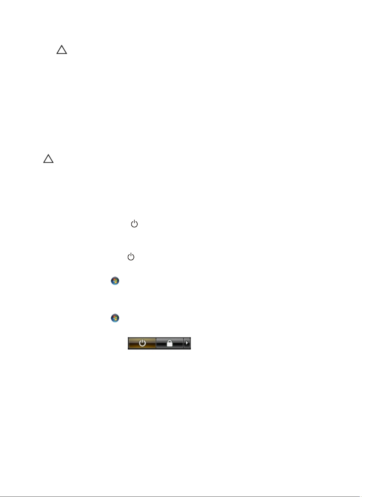
– In Windows 7:
1. Click Start .
2. Click Shut Down.
or
1. Click Start .
2. Click the arrow in the lower-right corner of the Start menu as shown below, and then click Shut
Down..
2. Ensure that the computer and all attached devices are turned off. If your computer and attached devices did not
automatically turn off when you shut down your operating system, press and hold the power button for about 6
seconds to turn them off.
After Working Inside Your Computer
After you complete any replacement procedure, ensure you connect any external devices, cards, and cables before
turning on your computer.
1. Replace the cover.
8
Page 9

CAUTION: To connect a network cable, first plug the cable into the network device and then plug it into the
computer.
2. Connect any telephone or network cables to your computer.
3. Connect your computer and all attached devices to their electrical outlets.
4. Turn on your computer.
5. If required, verify that the computer works correctly by running the Dell Diagnostics.
9
Page 10

10
Page 11
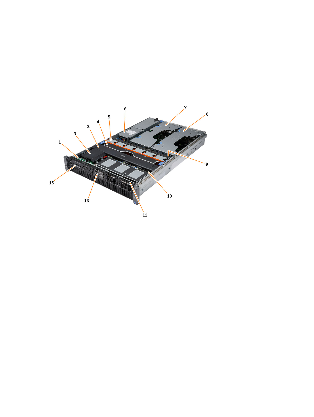
System Overview
The figure below displays the inside view of the computer after the front bezel and the cover have been removed. The
callouts show the names and the layout of the components inside the computer.
2
1. control panel
2. plastic cover
3. cooling shroud
4. fan bracket
5. system fans
6. power distribution unit
7. center expansion-card cage
8. outer expansion-card cage
9. coin-cell battery
10. SAS back plane
11. front-chassis assembly
12. hard drive
13. optical drive
11
Page 12

12
Page 13
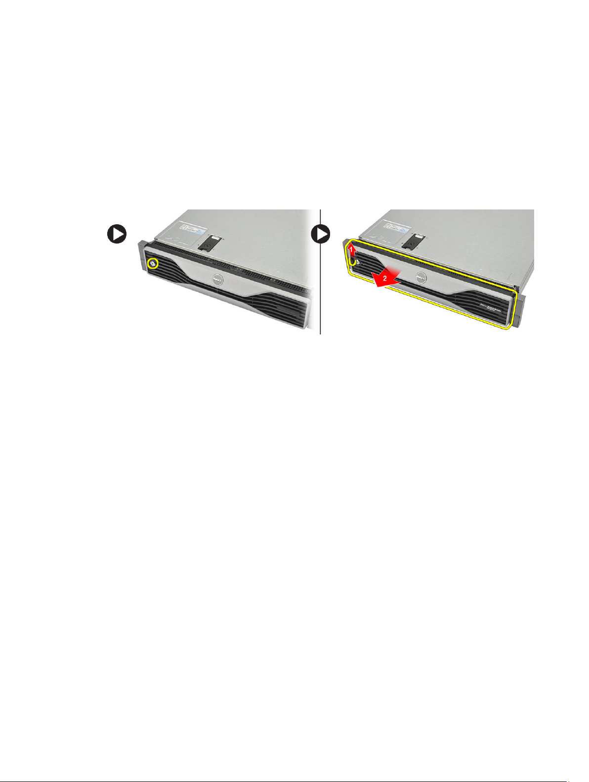
Removing the Front Bezel
3
1. Follow the procedures in
2. Unlock the front bezel using the key provided.
a) Lift the bezel-release tab and pull the front bezel away from the computer.
Before Working Inside Your Computer
.
13
Page 14

14
Page 15

Installing the Front Bezel
1. Insert the front bezel in its slot in a downward direction and push it towards the computer.
2. Secure the release tab.
3. Lock the front bezel using the key provided.
4. Follow the procedures in
After Working Inside Your Computer
.
4
15
Page 16

16
Page 17
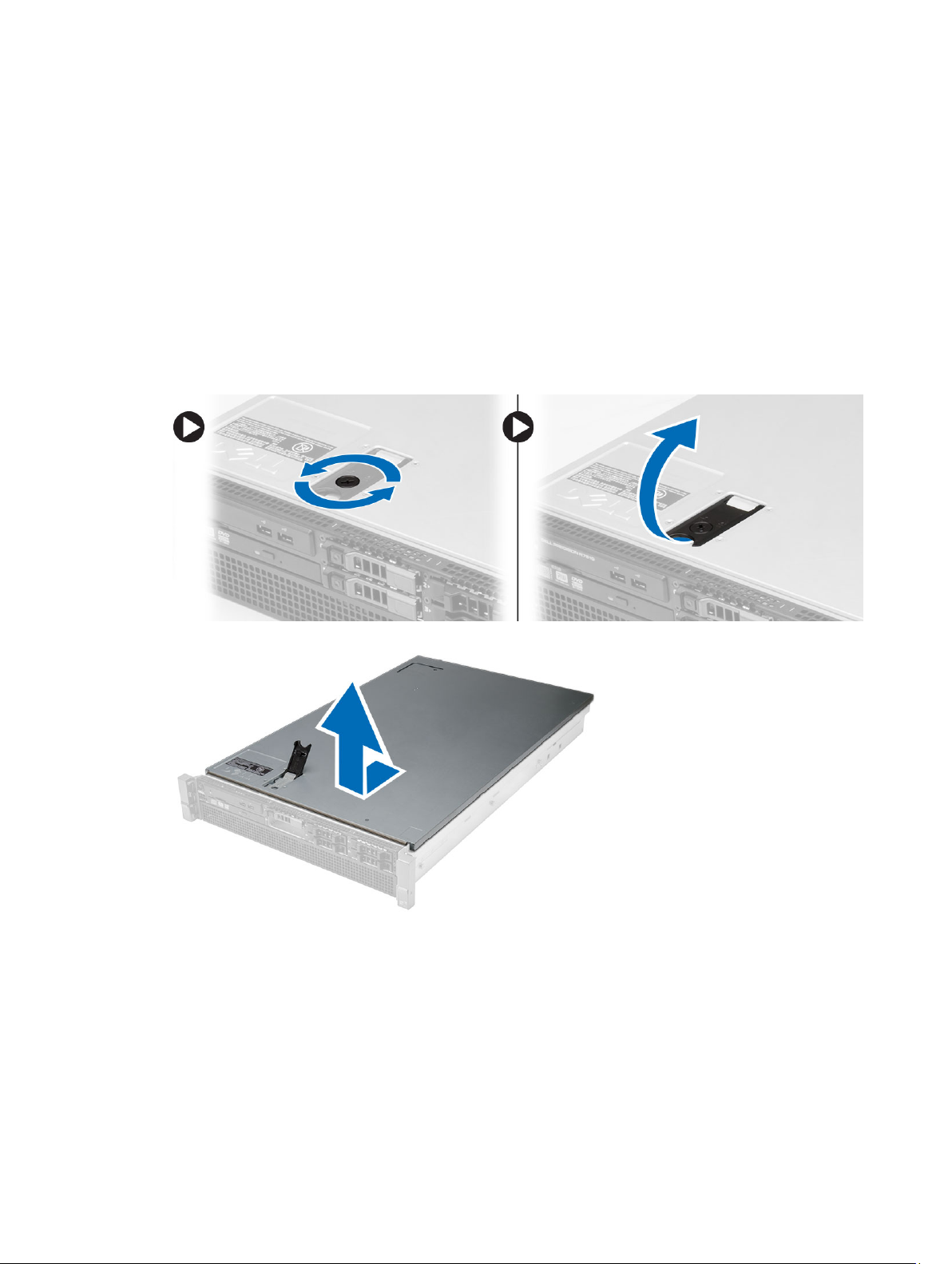
Removing the Cover
5
1. Follow the procedures in
2. Remove:
– front bezel
3. Rotate the latch-release lock counter-clockwise to the unlocked position.
a) Lift the latch and slide the cover towards the back of the computer.
4. Lift the cover away from the computer.
Before Working Inside Your Computer
.
17
Page 18

18
Page 19

Installing the Cover
1. Place the cover on the computer and press it down until it clicks into place.
2. Press down the cover latch.
3. Install the front bezel.
4. Follow the procedures in
After Working Inside Your Computer
.
6
19
Page 20

20
Page 21
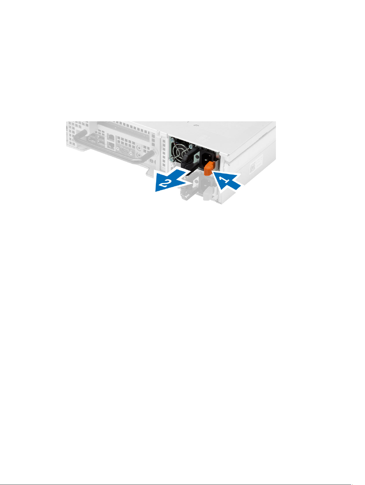
Removing the Power Supply
7
1. Follow the procedures in
2. Press and hold the orange tab towards the latch and pull the power supply unit away from the computer.
Before Working Inside Your Computer
.
21
Page 22

22
Page 23

Installing the Power Supply Unit
1. Insert the power supply unit into the computer until it clicks into place.
2. Follow the procedures in
After Working Inside Your Computer
.
8
23
Page 24

24
Page 25
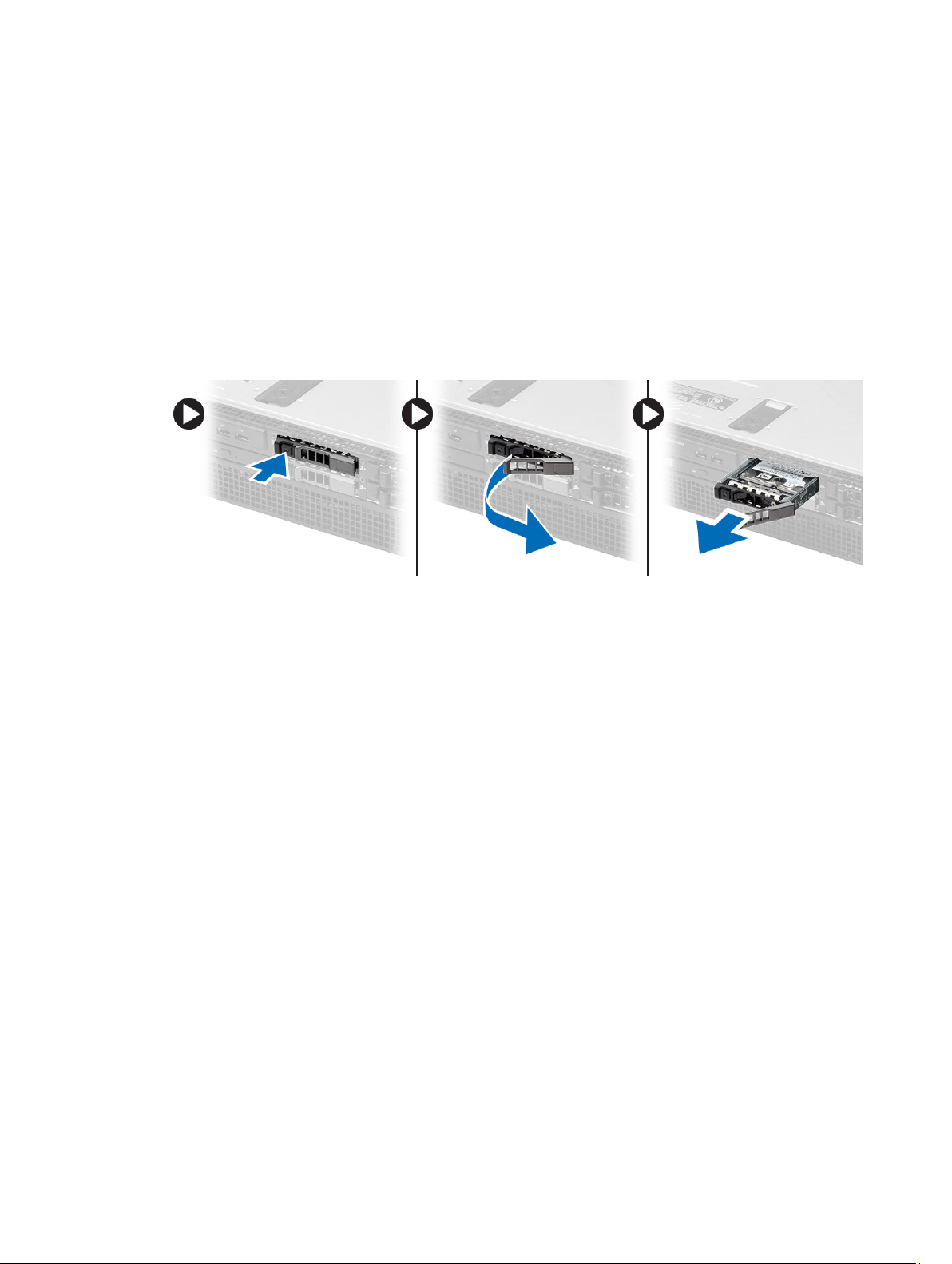
Removing the Hard Drive Carrier
9
1. Follow the procedures in
2. Remove the front bezel.
3. Press the hard-drive carrier release button.
a) Pull the hard-drive carrier handle open.
b) Slide the hard drive out of the drive bay.
Before Working Inside Your Computer
.
25
Page 26

26
Page 27

Installing the Hard Drive Carrier
1. Insert the hard drive into the drive bay.
2. Press the hard-drive carrier handle until it clicks into place.
3. Install the front bezel.
4. Follow the procedures in
After Working Inside Your Computer
.
10
27
Page 28

28
Page 29
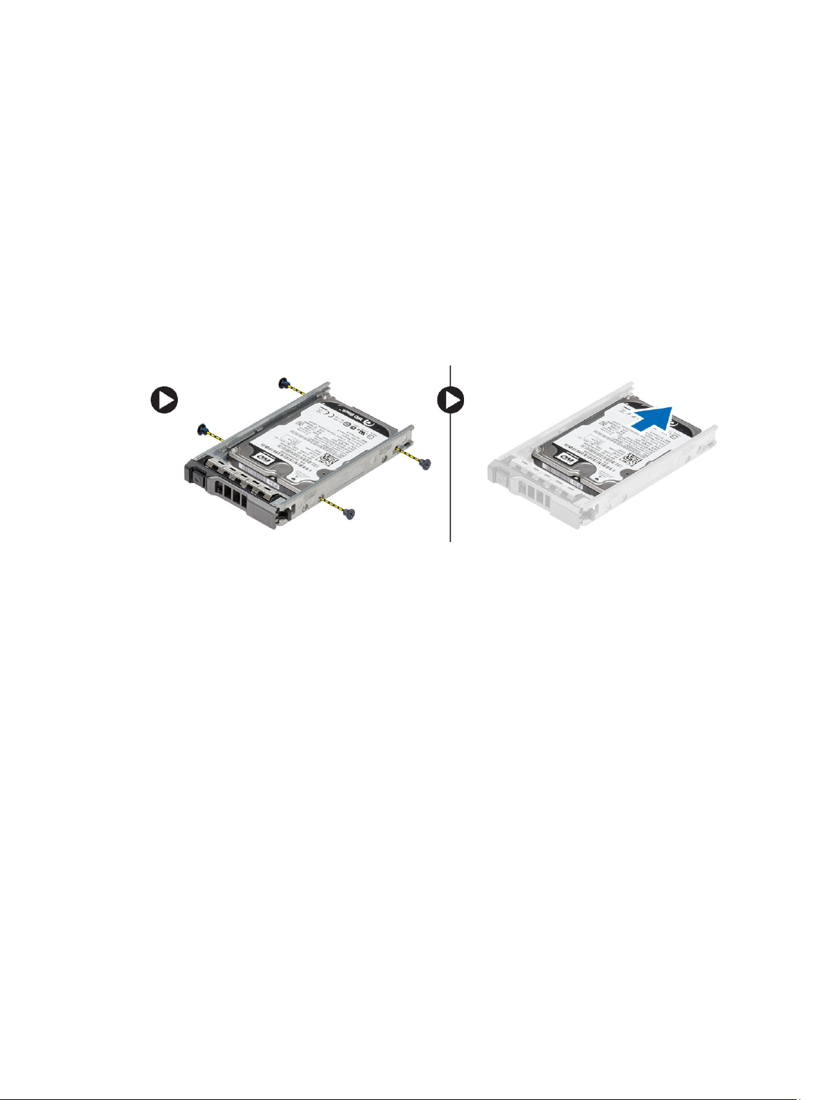
Removing the Hard Drive Assembly
11
1. Follow the procedures in
2. Remove:
– front bezel
– hard drive carrier
3. Remove the screws that secure the hard drive caddy to the hard drive.
a) Slide the hard drive out of the drive assembly.
Before Working Inside Your Computer
.
29
Page 30

30
Page 31

Installing the Hard Drive Assembly
1. Place the hard drive in the hard-drive caddy.
2. Tighten the screws that secure the hard drive on either side of the hard-drive caddy.
3. Install :
– hard drive carrier
– front bezel
4. Follow the procedures in
After Working Inside Your Computer
.
12
31
Page 32

32
Page 33

Removing the Control Panel
CAUTION: Two different Torx screwdrivers are needed for the control panel disassembly/reassembly, a T10 and T8.
13
1. Follow the procedures in
2. Remove:
– front bezel
– cover
3. Remove the torx screw that secures the control panel.
a) Disconnect the control panel cables.
b) Remove the screws that secure the control panel board.
Before Working Inside Your Computer
.
33
Page 34

34
Page 35

Installing the Control Panel
1. Connect the control panel cables.
2. Install the screws that secure the control panel.
3. Replace the torx screw that secures the control panel.
4. Install :
– cover
– front bezel.
5. Follow the procedures in
After Working Inside Your Computer
14
.
35
Page 36

36
Page 37

Removing the Optical Drive
15
1. Follow the procedures in
2. Remove:
– front bezel
– cover
– cooling shroud
3. Push the blue release tab in the direction indicated and lift the plastic cover.
a) Release the plastic cover from the hinges that secure it on the other side and remove it from the computer.
4. Disconnect the power and data cables from the optical drive.
a) Press down and push the blue release tab towards the front of the computer.
b) Slide the optical drive out through the front of the computer .
Before Working Inside Your Computer
.
37
Page 38

38
Page 39

16
Installing the Optical Drive
1. Insert the optical drive into the drive bay.
2. Connect the power and data cables.
3. Replace the plastic cover by securing the tabs on one side to the metal hinges and by pressing down the other side
until it clicks into place.
4. Install:
– cooling shroud
– cover
– front bezel
5. Follow the procedures in
After Working Inside Your Computer
.
39
Page 40

40
Page 41

Removing the Cooling Shroud
17
1. Follow the procedures in
2. Remove:
– front bezel
– cover
3. Lift the cooling shroud straight up and away from the system board.
Before Working Inside Your Computer
.
41
Page 42

42
Page 43

Installing the Cooling Shroud
1. Place the cooling shroud in front of the system fans into the system board.
2. Install:
18
– cover
– front bezel
3. Follow the procedures in
After Working Inside Your Computer
.
43
Page 44

44
Page 45

Removing the SAS (Serial attached SCSI) Backplane
19
1. Follow the procedures in
2. Remove:
– front bezel
– cover
– cooling shroud
– optical drive
– hard-drive carrier
– hard-drive assembly
3. Disconnect all the SAS cables by pressing on their respective release tabs.
Before Working Inside Your Computer
.
4. Push the blue release tabs in the direction of the arrows towards the hard-drive assembly to release the SAS
backplane from the system board.
a) Lift and remove the SAS backplane from the computer.
45
Page 46

46
Page 47

20
Installing the SAS (Serial Attached SCSI) backplane
1. Push the blue release tabs and insert the backplane in the slot on the system board along the hard-drive assembly.
2. Connect the SAS cables.
3. Install:
– hard-drive assembly
– hard-drive carrier
– optical drive
– cooling shroud
– cover
– front bezel
4. Follow the procedures in
After Working Inside Your Computer
.
47
Page 48

48
Page 49

Removing the Front-Chassis Assembly
21
1. Follow the procedures in
2. Remove:
– front bezel
– cover
– cooling shroud
3. Press inwards on the two release tabs and slide the front-chassis assembly towards the front of the computer .
Before Working Inside Your Computer
.
49
Page 50

50
Page 51

Installing the Front-Chassis Assembly
1. Slide the front-chassis assembly towards the back of the computer until it clicks into place.
2. Install:
– cooling shroud
– cover
– front bezel
3. Follow the procedures in
After Working Inside Your Computer
.
22
51
Page 52

52
Page 53

Removing the Fan Bracket
23
1. Follow the procedures in
2. Remove:
– cover
– cooling shroud
3. Pull both release tabs upwards simultaneously to release the fan bracket.
a) Lift the fan-bracket and remove it from the computer.
Before Working Inside Your Computer
.
53
Page 54

54
Page 55

Installing the Fan Bracket
1. Place the fan bracket in the computer.
2. Ensure that there are no cables on top of the fan connectors.
3. Press both release tabs downwards simultaneously to secure the bracket.
4. Install:
– cooling shroud
– cover
5. Follow the procedures in
After Working Inside Your Computer
.
24
55
Page 56

56
Page 57

Removing the System Fans
25
1. Follow the procedures in
2. Remove:
– cover
– front chassis assembly
3. Press the release tab and lift the fan out of the system fan assembly.
a) Repeat the above step to remove the remaining system fans from the assembly.
Before Working Inside Your Computer
.
57
Page 58

58
Page 59

Installing the System Fans
1. Insert the fan in the system fan assembly until it clicks into place.
2. Repeat the above step to install the remaining system fans into the assembly.
3. Install:
– front chassis assembly
– cover
4. Follow the procedures in
After Working Inside Your Computer
.
26
59
Page 60

60
Page 61

Removing the Coin-Cell Battery
27
1. Follow the procedures in
2. Remove:
– front bezel
– cover
– cooling shroud
– fan bracket
3. Press the release latch away from the battery to allow the battery to pop-up from the socket. Lift the coin-cell
battery out of the computer.
Before Working Inside Your Computer
.
61
Page 62

62
Page 63

Installing the Coin-Cell Battery
1. Place the coin-cell battery into the slot on the system board.
2. Press the coin-cell battery downward until the release latch springs back into place and secures it.
3. Install:
– fan bracket
– cooling shroud
– cover
– front bezel
4. Follow the procedures in
After Working Inside Your Computer
.
28
63
Page 64

64
Page 65

Removing the Memory
29
1. Follow the procedures in
2. Remove:
– front bezel
– cover
– cooling shroud
– front chassis assembly
– fan bracket
3. Press down on the memory-securing clips on each side of the memory module, and lift the memory module
upwards to remove it from the computer.
Before Working Inside Your Computer
.
65
Page 66

66
Page 67

Installing the Memory
1. Insert the memory module into the memory socket.
2. Press down on the memory module until the securing clips secure the memory in place.
3. Install:
– fan bracket
– front chassis assembly
– cooling shroud
– cover
– front bezel
4. Follow the procedures in
After Working Inside Your Computer
.
30
67
Page 68

68
Page 69

Removing the Heat Sink
31
1. Follow the procedures in
2. Remove:
– front bezel
– cover
– cooling shroud
– fan bracket
3. Slide the front chassis assembly forward.
4. Loosen the captive screws on the heat sink. It is recommended to begin loosening the diagonal-facing screws to
prevent one side of the heat sink from lifting during removal.
a) Lift the heat sink and remove it from the computer.
Before Working Inside Your Computer
.
69
Page 70

70
Page 71

Installing the Heat Sink
1. Place the heat sink over the processor on the system board.
2. Tighten and secure the diagonally-facing captive screws on the heat sink.
3. Install:
– fan bracket
– front-chassis assembly
– cooling shroud
– cover
– front bezel
4. Follow the procedures in
After Working Inside Your Computer
.
32
71
Page 72

72
Page 73

Removing the Processor
33
1. Follow the procedures in
2. Remove:
– front bezel
– cover
– cooling shroud
– front chassis assembly
– fan bracket
– heat sink
3. To remove the processor:
NOTE: The processor cover is secured by two levers. They have icons that indicate which lever needs to be
opened first and which lever closes first.
a) Press down on the first lever holding the processor cover in place and release it sideways from its retention
hook.
b) Repeat step 'a' to release the second lever from its retention hook.
c) Lift up and remove the processor cover.
d) Lift the processor to remove it from the socket and place it in antistatic package.
Before Working Inside Your Computer
.
73
Page 74

4. Repeat the above steps to remove the second processor (if available) from the computer.
To verify if your computer has dual processor slots, see the System Board Components.
74
Page 75

Installing the Processor
1. Place the processor in its socket.
2. Replace the processor cover.
NOTE: The processor cover is secured by two levers. They have icons that indicate which lever needs to be
opened first and which lever closes first
3. Slide the first lever sideways into the retention hook to secure the processor.
4. Repeat step '3' to slide the second lever into the retention hook.
5. Install:
– heat sink
– fan bracket
– front chassis assembly
– cooling shroud
– cover
– front bezel
6. Follow the procedures in
After Working Inside Your Computer
.
34
75
Page 76

76
Page 77

Removing the Expansion Card Cages
35
1. Follow the procedures in
2. Remove:
– front bezel
– cover
3. Release the power cables from the metal clips .
Before Working Inside Your Computer
.
4. Lift the outer expansion-card cage and flip it over.
77
Page 78

5. Disconnect all the cables leading up to the outer expansion-card cage and lift it away from the computer.
6. Disconnect all the cables leading up to the center expansion-card cage.
78
Page 79

7. Lift the center expansion-card upwards and move it away from the computer.
79
Page 80

80
Page 81

Installing the Expansion Card Cages
1. Connect the cables leading to the center expansion-card cage.
2. Install the center expansion-card cage in the computer.
3. Connect the cables leading to the outer expansion-card cage.
4. Install the outer expansion-card cage in the computer.
5. Thread the cables leading to the expansion card cage.
6. Install:
– cover
– front bezel
7. Follow the procedures in
After Working Inside Your Computer
.
36
81
Page 82

82
Page 83

Removing the Power-Distribution Unit
37
1. Follow the procedures in
2. Remove:
– front bezel
– cover
– cooling shroud
– power supply
– system fans
– fan bracket
3. Slide the front chassis assembly forward.
4. Disconnect the optical drive power connector and the SAS backplane connector by pressing the notch on each
individual connector and pulling them in an outward direction.
Before Working Inside Your Computer
.
5. Disconnect the CPU 1, CPU 2 power connectors, CPU 1, CPU 2 memory power connectors, power-distribution unit
connector and the 24–pin connector from the system board.
83
Page 84

6. Unroute all the cables from the routing tabs.
7. Remove the screws that secure the power-distribution unit.
a) Lift the power-distribution unit upwards and remove it from the computer.
84
Page 85

Installing the Power-Distribution Unit
1. Place the power-distribution unit on the computer.
2. Install the screws that secure the power distribution unit.
3. Route all the power cables through their routing channels.
4. Connect the CPU 1, CPU 2, SAS Backplane and optical driver power connectors.
5. Slide the front chassis assembly to its original position.
6. Install:
– expansion card cages
– fan bracket
– system fans
– hard-drive assembly
– cooling shroud
– cover
– front bezel
7. Follow the procedures in
After Working Inside Your Computer
.
38
85
Page 86

86
Page 87

Removing the Remote Access Host Card
39
1. Follow the procedures in
2. Remove:
– front bezel
– cover
– expansion card cages
3. Remove all the cards from the card riser cage.
4. Lift the release tab upwards and slide the riser board towards the right to remove it from the computer.
Before Working Inside Your Computer
.
87
Page 88

88
Page 89

Installing the Remote Access Host Card
1. Install the remote access host card in its slot.
2. Install:
– expansion card cages
– cover
– front bezel
3. Follow the procedures in
After Working Inside Your Computer
.
40
89
Page 90

90
Page 91

Removing the SAS Controller Card
41
1. Follow the procedures in
2. Remove:
– front bezel
– cover
– expansion card cages
– remote access host card
3. Remove the screws that secure the SAS controller card and remove it from the computer.
Before Working Inside Your Computer
.
91
Page 92

92
Page 93

Installing the SAS Controller Card
1. Install the screws that secure the SAS controller card.
2. Install:
– remote access host card
– expansion card cages
– cover
– front bezel
3. Follow the procedures in
After Working Inside Your Computer
.
42
93
Page 94

94
Page 95

Removing the System Board
43
1. Follow the procedures in
2. Remove:
– front bezel
– cover
– cooling shroud
– heat sink
– processor
– memory
– front-chassis assembly
– power supply
– fan bracket
– expansion card cages
– power distribution unit
3. Lift the blue release tab, slide the system board forward in the direction indicated and remove it from the computer.
Before Working Inside Your Computer
.
95
Page 96

96
Page 97

Installing the System Board
1. Place the system board on the chassis.
2. Slide the system board towards the back of the computer.
3. Press the blue release tab.
4. Install:
– power distribution unit
– expansion card cages
– fan bracket
– memory
– processor
– heat sink
– front-chassis assembly
– cooling shroud
– cover
– front bezel
5. Follow the procedures in
After Working Inside Your Computer
44
.
97
Page 98

98
Page 99

System Board Components
The following image displays the system board components .
45
1. DIMM slots
2. System-fan connectors
3. Front-panel connector
4. CPU 2 memory power connector
5. Power-distribution unit connector
6. 24-pin power connector
7. Front USB connector
8. I/O riser bus
9. SAS connectors
10. PCIe G2 S7 bus connector
11. I/O riser bus
12. SATA connector
13. coin-cell battery slot
14. CPU 1 memory power connector
15. Password reset jumper
16. Real-time clock reset jumper
17. Processor 1 power connector
18. Processor 1
19. Processor 2 power connector
20. Processor 2
99
Page 100

100
 Loading...