

Page 1

Dell Precision R5500 Owner's Manual
Regulatory Model: E15S
Regulatory Type: E15S001
Page 2

Notes, Cautions, and Warnings
NOTE: A NOTE indicates important information that helps you make better use of your computer.
CAUTION: A CAUTION indicates potential damage to hardware or loss of data if instructions are not followed.
WARNING: A WARNING indicates a potential for property damage, personal injury, or death.
Information in this publication is subject to change without notice.
© 2011 Dell Inc. All rights reserved.
Reproduction of these materials in any manner whatsoever without the written permission of Dell Inc. is strictly forbidden.
Trademarks used in this text: Dell™, the DELL logo, Dell Precision™, Precision ON™,ExpressCharge™, Latitude™, Latitude ON™,
OptiPlex™, Vostro™, and Wi-Fi Catcher™ are trademarks of Dell Inc. Intel®, Pentium®, Xeon®, Core™, Atom™, Centrino®, and Celeron
are registered trademarks or trademarks of Intel Corporation in the U.S. and other countries. AMD® is a registered trademark and
AMD Opteron™, AMD Phenom™, AMD Sempron™, AMD Athlon™, ATI Radeon™, and ATI FirePro™ are trademarks of Advanced Micro
Devices, Inc. Microsoft®, Windows®, MS-DOS®, Windows Vista®, the Windows Vista start button, and Office Outlook® are either
trademarks or registered trademarks of Microsoft Corporation in the United States and/or other countries. Blu-ray Disc™ is a trademark
owned by the Blu-ray Disc Association (BDA) and licensed for use on discs and players. The Bluetooth® word mark is a registered
trademark and owned by the Bluetooth
trademark of Wireless Ethernet Compatibility Alliance, Inc.
Other trademarks and trade names may be used in this publication to refer to either the entities claiming the marks and names or their
products, Dell Inc. disclaims any proprietary interest in trademarks and trade names other than its own.
2011 — 6
®
SIG, Inc. and any use of such mark by Dell Inc. is under license.
Wi-Fi
®
is a registered
®
Rev. A00
Page 3

Contents
Notes, Cautions, and Warnings...................................................................................................2
1 Working on Your Computer.......................................................................................................9
Before Working Inside Your Computer.....................................................................................................................9
Recommended Tools..............................................................................................................................................10
Turning Off Your Computer.....................................................................................................................................10
After Working Inside Your Computer......................................................................................................................10
2 Front Bezel..................................................................................................................................11
Removing the Front Bezel.......................................................................................................................................11
Installing the Front Bezel........................................................................................................................................11
3 Cover...........................................................................................................................................13
Removing the Cover................................................................................................................................................13
Installing the Cover.................................................................................................................................................14
4 Cooling Shroud..........................................................................................................................15
Removing the Cooling Shroud.................................................................................................................................15
Installing the Cooling Shroud..................................................................................................................................16
5 Optical Drive...............................................................................................................................17
Removing the Optical Drive....................................................................................................................................17
Installing the Optical Drive.....................................................................................................................................18
6 Hard Drive Carrier.....................................................................................................................19
Removing the Hard-Drive Carrier...........................................................................................................................19
Installing the Hard-Drive Carrier............................................................................................................................20
7 Hard Drive Assembly................................................................................................................21
Removing the Hard-Drive Assembly.......................................................................................................................21
Installing the Hard-Drive Assembly........................................................................................................................22
8 SAS Backplane..........................................................................................................................23
Removing the SAS Backplane................................................................................................................................23
Installing the SAS Backplane.................................................................................................................................24
9 Power Supply.............................................................................................................................25
Removing the Power Supply...................................................................................................................................25
Page 4

Installing the Power Supply....................................................................................................................................25
10 Control Panel............................................................................................................................27
Removing the Control Panel...................................................................................................................................27
Installing the Control Panel.....................................................................................................................................28
11 System Fan...............................................................................................................................29
Removing the System Fans.....................................................................................................................................29
Installing the System Fans......................................................................................................................................30
12 Fan Bracket..............................................................................................................................31
Removing the Removable Fan Bracket...................................................................................................................31
Installing the Removable Fan Bracket....................................................................................................................32
13 Card Cages...............................................................................................................................33
Removing the Expansion Card Cages.....................................................................................................................33
Installing the Expansion Card Cages......................................................................................................................35
14 Power Distribution Unit..........................................................................................................37
Removing the Power Distribution Unit....................................................................................................................37
Installing the Power Distribution Unit.....................................................................................................................38
15 Center Riser Board..................................................................................................................41
Removing the Center Riser Board..........................................................................................................................41
Installing the Center Riser Board............................................................................................................................42
16 CMOS Battery..........................................................................................................................43
Removing the CMOS Battery..................................................................................................................................43
Installing the CMOS Battery...................................................................................................................................44
17 Video Card................................................................................................................................45
Removing the Video Card.......................................................................................................................................45
Installing the Video Card.........................................................................................................................................46
18 SAS Controller Card................................................................................................................47
Removing the SAS Controller Card.........................................................................................................................47
Installing the SAS Controller Card..........................................................................................................................48
RAID Configuration.................................................................................................................................................48
19 Remote Access Host Card.....................................................................................................51
Removing the Remote Access Host Card...............................................................................................................51
Installing the Remote Access Host Card................................................................................................................52
Page 5

20 Front Chassis Assembly.........................................................................................................53
Removing the Front Chassis Assembly...................................................................................................................53
Installing the Front-Chassis Assembly...................................................................................................................54
21 Processor and Heat Sink.......................................................................................................55
Removing the Processors and Heat Sink...............................................................................................................55
Installing the Processors and Heat Sink.................................................................................................................57
22 Memory.....................................................................................................................................59
Removing the Memory............................................................................................................................................59
Installing the Memory.............................................................................................................................................60
23 System Board...........................................................................................................................63
Removing the System Board...................................................................................................................................63
Installing the System Board....................................................................................................................................64
24 System Setup...........................................................................................................................67
Boot Menu..............................................................................................................................................................67
Timing Key Sequences...........................................................................................................................................68
Dell Diagnostics......................................................................................................................................................68
System Setup Options.............................................................................................................................................68
25 Troubleshooting.......................................................................................................................75
Diagnostic LEDs......................................................................................................................................................75
Beep Codes.............................................................................................................................................................81
Error Messages......................................................................................................................................................84
Address mark not found...................................................................................................................................84
Alert! Previous attempts at booting this system have failed at checkpoint [nnnn]. For help in resolving
this problem, please note this checkpoint and contact Dell Technical Support.............................................84
Alert! Security override Jumper is installed....................................................................................................84
Attachment failed to respond...........................................................................................................................84
Bad command or file name .............................................................................................................................84
Bad error-correction code (ECC) on disk read.................................................................................................84
Controller has failed.........................................................................................................................................84
Data error ........................................................................................................................................................84
Decreasing available memory .........................................................................................................................85
Diskette drive 0 seek failure.............................................................................................................................85
Diskette read failure.........................................................................................................................................85
Diskette subsystem reset failed.......................................................................................................................85
Gate A20 failure................................................................................................................................................85
General failure .................................................................................................................................................85
Page 6

Hard-disk drive configuration error .................................................................................................................85
Hard-disk drive controller failure.....................................................................................................................85
Hard-disk drive failure .....................................................................................................................................86
Hard-disk drive read failure.............................................................................................................................86
Invalid configuration information-please run SETUP program........................................................................86
Invalid Memory configuration, please populate DIMM1.................................................................................86
Keyboard failure...............................................................................................................................................86
Memory address line failure at address, read value expecting value ............................................................86
Memory allocation error..................................................................................................................................86
Memory data line failure at address, read value expecting value...................................................................86
Memory double word logic failure at address, read value expecting value....................................................87
Memory odd/even logic failure at address, read value expecting value.........................................................87
Memory write/read failure at address, read value expecting value................................................................87
Memory size in CMOS invalid..........................................................................................................................87
Memory tests terminated by keystroke............................................................................................................87
No boot device available..................................................................................................................................87
No boot sector on hard-disk drive....................................................................................................................87
No timer tick interrupt .....................................................................................................................................87
Non-system disk or disk error..........................................................................................................................88
Not a boot diskette...........................................................................................................................................88
Plug and play configuration error....................................................................................................................88
Read fault.........................................................................................................................................................88
Requested sector not found.............................................................................................................................88
Reset failed.......................................................................................................................................................88
Sector not found ..............................................................................................................................................88
Seek error ........................................................................................................................................................88
Shutdown failure .............................................................................................................................................88
Time-of-day clock stopped ..............................................................................................................................89
Time-of-day not set-please run the System Setup program ...........................................................................89
Timer chip counter 2 failed ..............................................................................................................................89
Unexpected interrupt in protected mode.........................................................................................................89
WARNING: Dell's Disk Monitoring System has detected that drive [0/1] on the [primary/secondary]
EIDE controller is operating outside of normal specifications. It is advisable to immediately back up
your data and replace your hard drive by calling your support desk or Dell...................................................89
Write fault.........................................................................................................................................................89
Write fault on selected drive............................................................................................................................89
X:\ is not accessible. The device is not ready .................................................................................................89
26 Specifications..........................................................................................................................91
Specifications.........................................................................................................................................................91
27 Contacting Dell........................................................................................................................97
Page 7

Contacting Dell.......................................................................................................................................................97
Page 8

8
Page 9
Working on Your Computer
Before Working Inside Your Computer
Use the following safety guidelines to help protect your computer from potential damage and to help to ensure your
personal safety. Unless otherwise noted, each procedure included in this document assumes that the following
conditions exist:
• You have read the safety information that shipped with your computer.
• A component can be replaced or--if purchased separately--installed by performing the removal procedure in
reverse order.
WARNING: Before working inside your computer, read the safety information that shipped with your computer. For
additional safety best practices information, see the Regulatory Compliance Homepage at www.dell.com/
regulatory_compliance.
CAUTION: Many repairs may only be done by a certified service technician. You should only perform
troubleshooting and simple repairs as authorized in your product documentation, or as directed by the online or
telephone service and support team. Damage due to servicing that is not authorized by Dell is not covered by your
warranty. Read and follow the safety instructions that came with the product.
CAUTION: To avoid electrostatic discharge, ground yourself by using a wrist grounding strap or by periodically
touching an unpainted metal surface, such as a connector on the back of the computer.
1
CAUTION: Handle components and cards with care. Do not touch the components or contacts on a card. Hold a
card by its edges or by its metal mounting bracket. Hold a component such as a processor by its edges, not by its
pins.
CAUTION: When you disconnect a cable, pull on its connector or on its pull-tab, not on the cable itself. Some
cables have connectors with locking tabs; if you are disconnecting this type of cable, press in on the locking tabs
before you disconnect the cable. As you pull connectors apart, keep them evenly aligned to avoid bending any
connector pins. Also, before you connect a cable, ensure that both connectors are correctly oriented and aligned.
NOTE: The color of your computer and certain components may appear differently than shown in this document.
To avoid damaging your computer, perform the following steps before you begin working inside the computer.
1. Ensure that your work surface is flat and clean to prevent the computer cover from being scratched.
2. Turn off your computer (see Turning Off Your Computer).
CAUTION: To disconnect a network cable, first unplug the cable from your computer and then unplug the
cable from the network device.
3. Disconnect all network cables from the computer.
4. Disconnect your computer and all attached devices from their electrical outlets.
5. Press and hold the power button while the computer is unplugged to ground the system board.
6. Remove the cover.
9
Page 10
CAUTION: Before touching anything inside your computer, ground yourself by touching an unpainted metal
surface, such as the metal at the back of the computer. While you work, periodically touch an unpainted metal
surface to dissipate static electricity, which could harm internal components.
Recommended Tools
The procedures in this document may require the following tools:
• Small flat-blade screwdriver
• Phillips screwdriver
• Small plastic scribe
• Flash BIOS update program media
Turning Off Your Computer
CAUTION: To avoid losing data, save and close all open files and exit all open programs before you turn off your
computer.
1. Shut down the operating system:
– In Windows 7:
Click Start , then click Shut Down.
– In Windows Vista:
Click Start , then click the arrow in the lower-right corner of the Start menu as shown below, and then
click Shut Down.
– In Windows XP:
Click Start → Turn Off Computer → Turn Off . The computer turns off after the operating system shutdown
process is complete.
2. Ensure that the computer and all attached devices are turned off. If your computer and attached devices did not
automatically turn off when you shut down your operating system, press and hold the power button for about 6
seconds to turn them off.
After Working Inside Your Computer
After you complete any replacement procedure, ensure you connect any external devices, cards, and cables before
turning on your computer.
1. Replace the cover.
CAUTION: To connect a network cable, first plug the cable into the network device and then plug it into the
computer.
2. Connect any telephone or network cables to your computer.
3. Connect your computer and all attached devices to their electrical outlets.
4. Turn on your computer.
5. Verify that the computer works correctly by running the Dell Diagnostics.
10
Page 11
Front Bezel
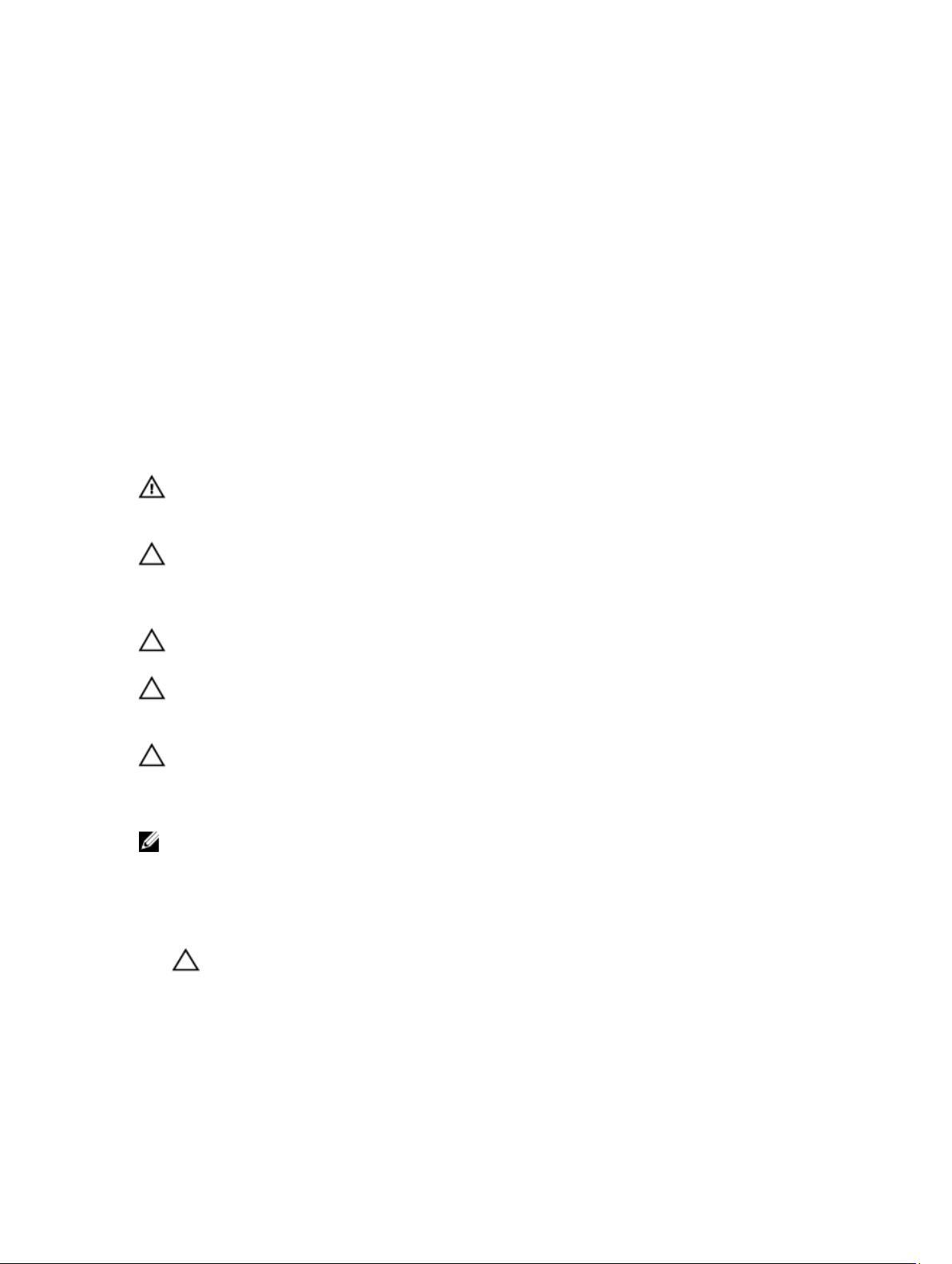
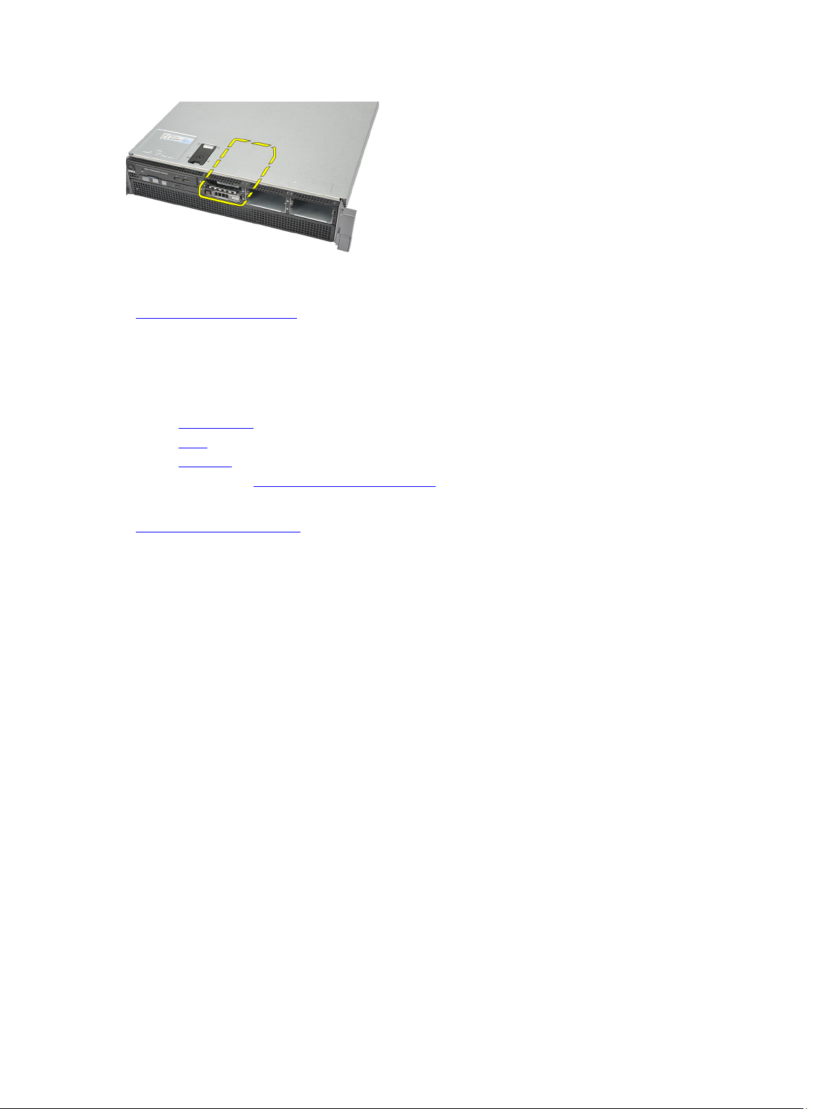
Removing the Front Bezel
1. Follow the procedures in Before Working Inside Your Computer.
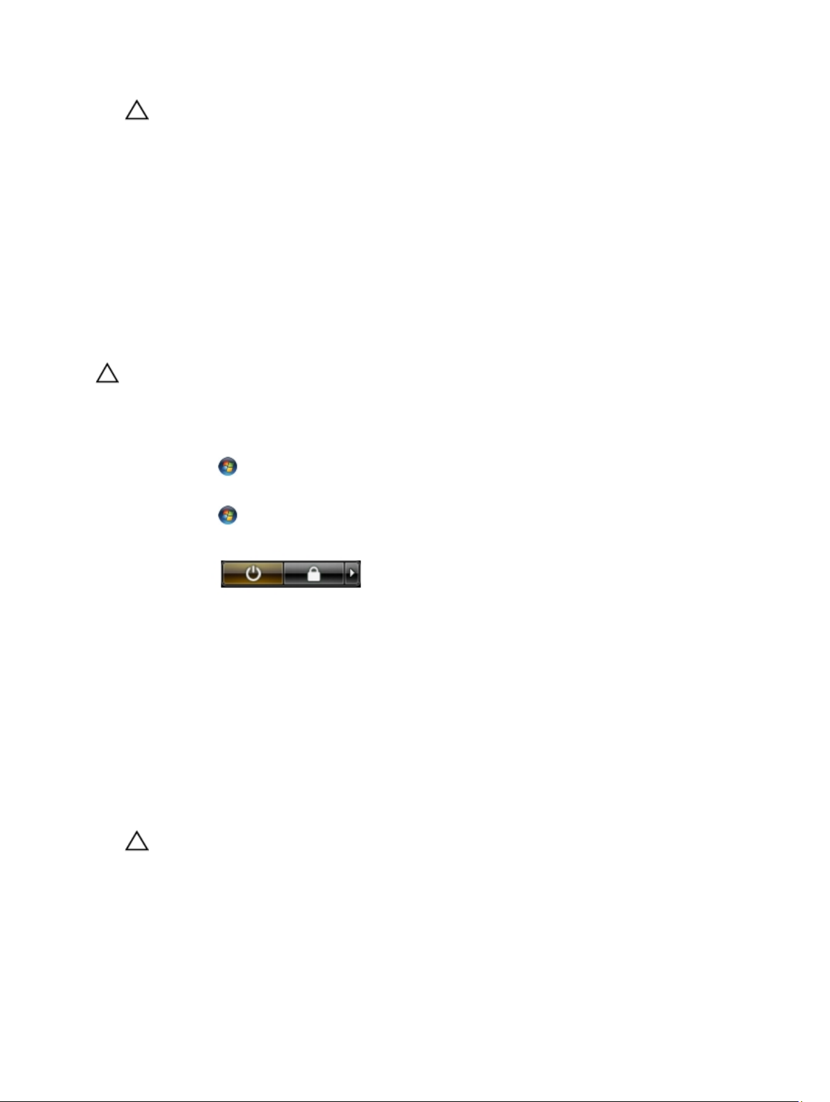
2. Unlock the front bezel using the given key.
3. Lift the bezel release tab and gently pull the front bezel away from the computer.
2
Related Links
Installing the Front Bezel
Installing the Front Bezel
1. Insert the front bezel in the slot downwards and push it towards the computer.
2. Secure the release tab.
3. Lock the front bezel using the given key.
4. Follow the procedures in After Working Inside Your Computer.
Related Links
Removing the Front Bezel
11
Page 12

12
Page 13
Cover
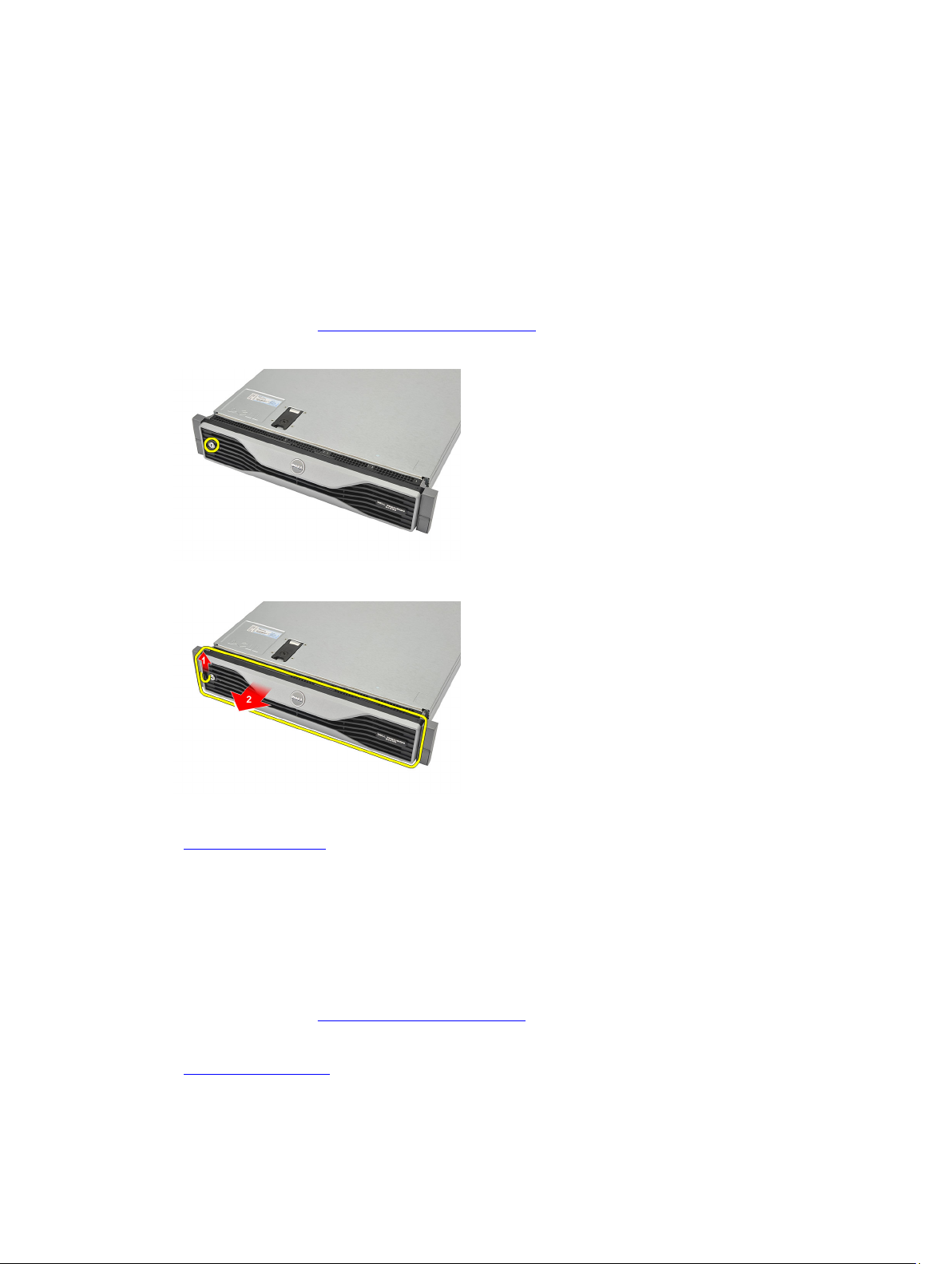
Removing the Cover
1. Follow the procedures in Before Working Inside Your Computer.
2. Remove the front bezel.
3. Rotate the latch-release lock counter-clockwise to the unlocked position.
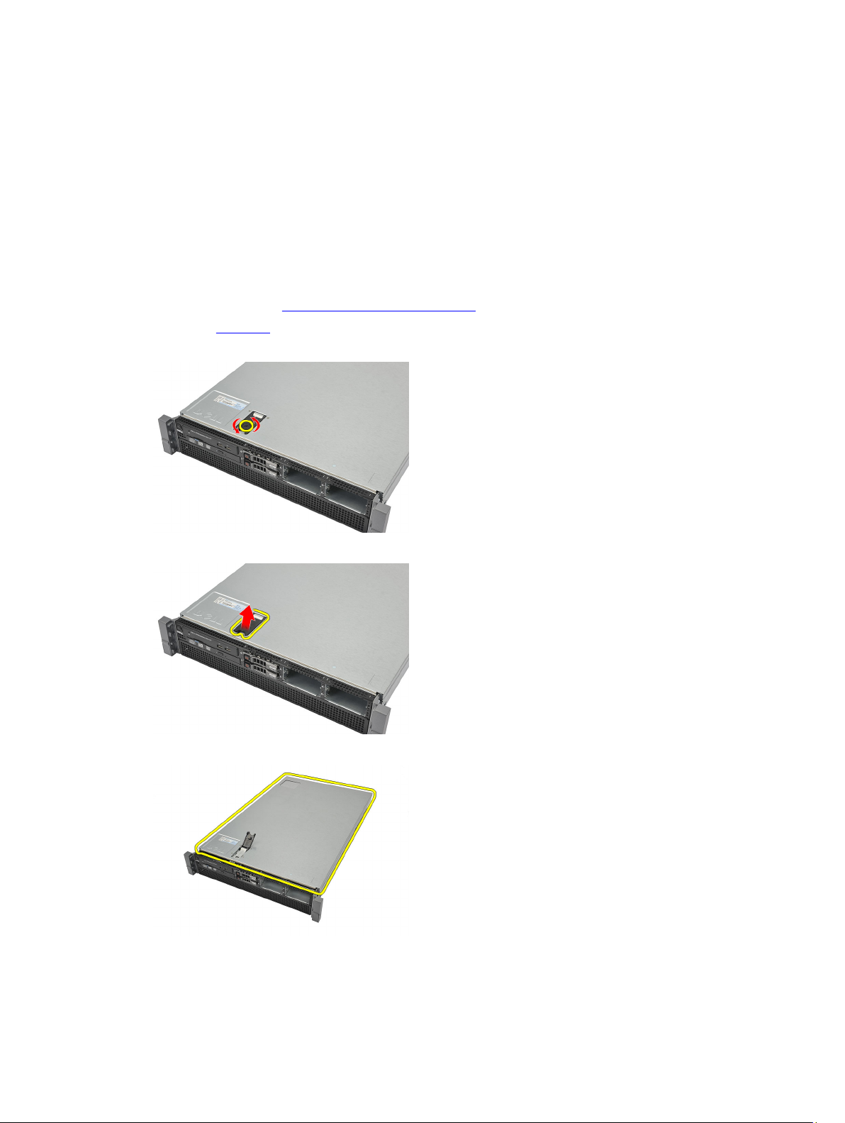
4. Lift the latch and slide the cover towards the back of the computer.
3
5. Hold the cover on both sides and lift it away from the computer.
Related Links
13
Page 14

Installing the Cover
Installing the Cover
1. Place the cover on the computer and press down until it clicks into place.
2. Press down the cover latch.
3. Using a screwdriver, rotate the latch-release lock clockwise, to lock the cover.
4. Install the front bezel.
5. Follow the procedures in After Working Inside Your Computer.
Related Links
Removing the Cover
14
Page 15
Cooling Shroud
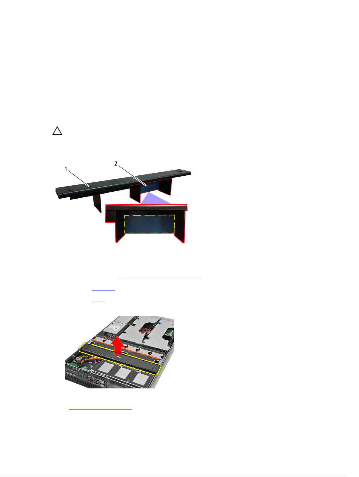
Removing the Cooling Shroud
CAUTION: The computer will be populated with one or two CPUs. Currently, when there is a single CPU installed,
airflow can bypass CPU1 which increases fan speeds and therefore leads to poor acoustic performance. Adding a
mylar piece in this region redirects airflow across CPU1. The mylar piece will need to be removed when the 2nd
CPU is installed as it is no longer needed and will interfere with the heat sink.
4
1. Cooling Shroud
2. Mylar — Needs to be removed if two CPUs are installed
1. Follow the procedures in Before Working Inside Your Computer.
2. Remove the front bezel.
3. Remove the cover.
4. Gently lift the shroud straight up and away from the system board.
Related Links
Installing the Cooling Shroud
15
Page 16

Installing the Cooling Shroud
1. Gently place the shroud in front of the system fans into the system board.
2. Install the cover.
3. Install the front bezel.
4. Follow the procedures in After Working Inside Your Computer.
Related Links
Removing the Cooling Shroud
16
Page 17
Optical Drive
Removing the Optical Drive
1. Follow the procedures in Before Working Inside Your Computer.
2. Remove the front bezel.
3. Remove the cover.
4. Remove the cooling shroud.
5. Disconnect the power and data cable from the back of the optical drive.
6. Press down and push the blue release tab toward the front of the computer.
5
7. Slide the optical drive through the front of the computer till it is free of the drive bay.
17
Page 18
Related Links
Installing the Optical Drive
Installing the Optical Drive
1. Insert the optical drive into the drive bay.
2. Connect the power and data cables.
3. Install the cooling shroud.
4. Install the cover.
5. Install the front bezel.
6. Follow the procedures in After Working Inside Your Computer.
Related Links
Removing the Optical Drive
18
Page 19
Hard Drive Carrier
Removing the Hard-Drive Carrier
1. Follow the procedures in Before Working Inside Your Computer.
2. Remove the front bezel.
3. Remove the cover.
4. Remove the cooling shroud.
5. Remove the optical drive.
6. Press the release button.
6
7. Pull the hard-drive carrier handle open.
8. Hold the front of the hard drive and slide out until it is free of the drive bay.
19
Page 20
Related Links
Installing the Hard-Drive Carrier
Installing the Hard-Drive Carrier
1. Insert the hard drive into the drive bay.
2. Press the hard-drive carrier handle until it clicks into place.
3. Install the cooling shroud.
4. Install the cover.
5. Install the front bezel.
6. Follow the procedures in After Working Inside Your Computer.
Related Links
Removing the Hard-Drive Carrier
20
Page 21
Hard Drive Assembly
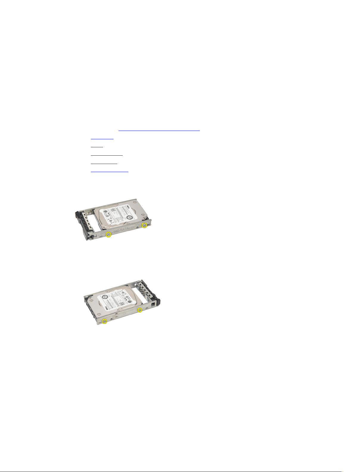
Removing the Hard-Drive Assembly
1. Follow the procedures in Before Working Inside Your Computer.
2. Remove the front bezel.
3. Remove the cover.
4. Remove the cooling shroud.
5. Remove the optical drive.
6. Remove the hard drive carrier.
7. Remove the screws securing the hard drive caddy to the hard drive.
7
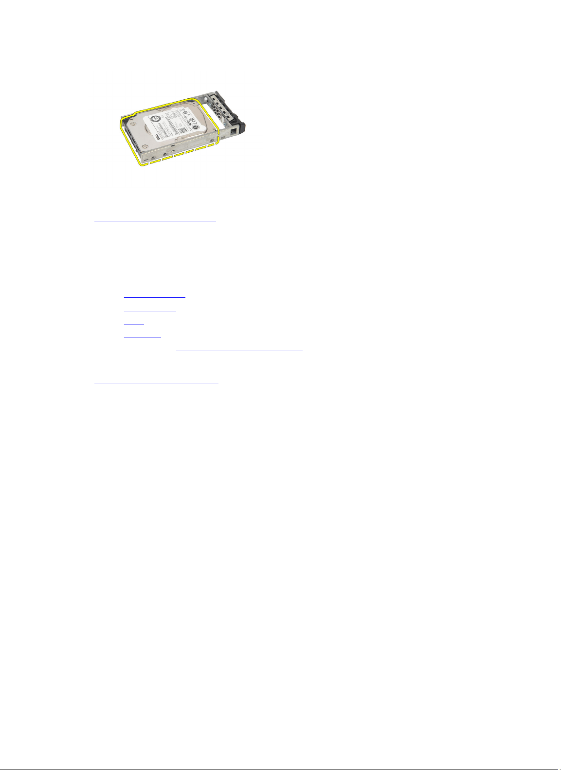
8. Rotate and repeat the same removal steps for the other side of the hard drive caddy.
9. Lift up the hard-drive caddy from the hard drive and remove.
21
Page 22
Related Links
Installing the Hard-Drive Assembly
Installing the Hard-Drive Assembly
1. Place the hard drive in the hard-drive caddy.
2. Tighten the screws that secure the hard drive on either side of the hard-drive caddy.
3. Install the hard drive carrier.
4. Install the cooling shroud.
5. Install the cover.
6. Install the front bezel.
7. Follow the procedures in After Working Inside Your Computer.
Related Links
Removing the Hard-Drive Assembly
22
Page 23
SAS Backplane
Removing the SAS Backplane
1. Follow the procedures in Before Working Inside Your Computer.
2. Remove the front bezel.
3. Remove the cover.
4. Remove the cooling shroud.
5. Remove the optical drive.
6. Remove the hard drive carrier.
7. Remove the hard-drive assembly.
8. Disconnect the SAS cables.
8
9. Push the blue release tabs in the direction of the arrows marked on the hard-drive housing assembly. Slide the
backplane upwards.
Related Links
Installing the SAS Backplane
23
Page 24

Installing the SAS Backplane
1. Push the blue release tabs and insert the backplane in the slot along the hard-drive assembly.
2. Connect the SAS cables.
3. Install the hard drive assembly.
4. Install the hard drive carrier.
5. Install the optical drive.
6. Install the cooling shroud.
7. Install the cover.
8. Install the front bezel.
9. Follow the procedures in After Working Inside Your Computer.
Related Links
Removing the SAS Backplane
24
Page 25
Power Supply
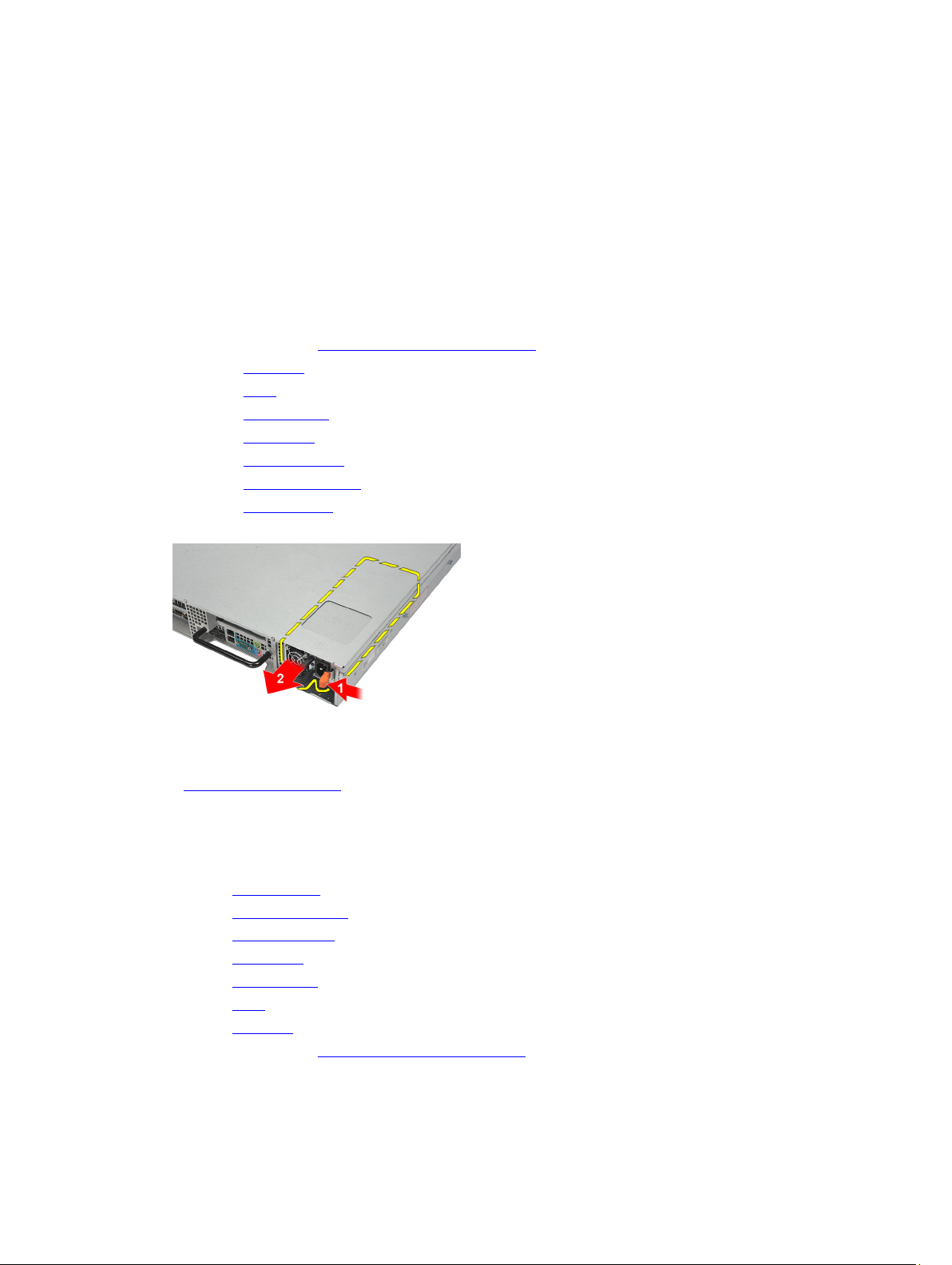
Removing the Power Supply
1. Follow the procedures in Before Working Inside Your Computer.
2. Remove the front bezel.
3. Remove the cover.
4. Remove the cooling shroud.
5. Remove the optical drive.
6. Remove the hard drive carrier.
7. Remove the hard-drive assembly.
8. Remove the SAS Backplane.
9. Press and hold the orange tab towards latch. Then pull the power supply unit away from the computer.
9
Related Links
Installing the Power Supply
Installing the Power Supply
1. Insert the power supply unit into the computer until it clicks into place.
2. Install the SAS backplane.
3. Install the hard drive assembly.
4. Install the hard-drive carrier.
5. Install the optical drive.
6. Install the cooling shroud.
7. Install the cover.
8. Install the front bezel.
9. Follow the procedures in After Working Inside Your Computer.
Related Links
25
Page 26

Removing the Power Supply
26
Page 27
Control Panel
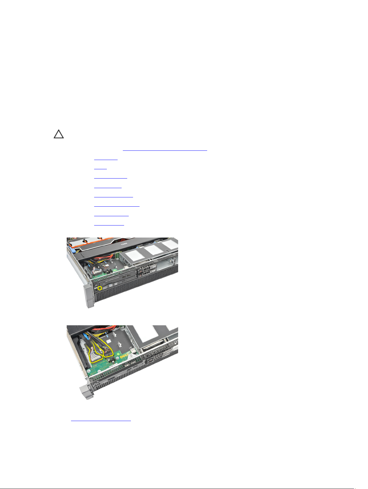
Removing the Control Panel
CAUTION: Two different Torx drivers are needed for the control panel disassembly/reassembly, a T10 and T8.
1. Follow the procedures in Before Working Inside Your Computer.
2. Remove the front bezel.
3. Remove the cover.
4. Remove the cooling shroud.
5. Remove the optical drive.
6. Remove the hard drive carrier.
7. Remove the hard-drive assembly.
8. Remove the SAS Backplane.
9. Remove the power supply.
10. Locate and remove the torx screw securing the control panel.
10
11. Remove the control panel cables.
Related Links
Installing the Control Panel
27
Page 28

Installing the Control Panel
1. Attach the control panel cables.
2. Replace the torx screw securing the control panel.
3. Install the power supply.
4. Install the SAS backplane.
5. Install the hard drive assembly.
6. Install the hard-drive carrier.
7. Install the optical drive.
8. Install the cooling shroud.
9. Install the cover.
10. Install the front bezel.
11. Follow the procedures in After Working Inside Your Computer.
Related Links
Removing the Control Panel
28
Page 29
System Fan
Removing the System Fans
1. Follow the procedures in Before Working Inside Your Computer.
2. Remove the front bezel.
3. Remove the cover.
4. Remove the cooling shroud.
5. Remove the optical drive.
6. Remove the hard drive carrier.
7. Remove the hard-drive assembly.
8. Remove the SAS Backplane.
9. Remove the power supply.
10. Remove the control panel.
11. Press the release tab and lift the fan out of the cooling fan assembly.
11
12. Repeat step 11 to remove the remaining five cooling fans.
Related Links
Installing the System Fans
29
Page 30

Installing the System Fans
1. Insert the fan in the cooling fan assembly until it clicks into place.
2. Repeat step 1 for the remaining cooling fans.
3. Install the control panel.
4. Install the power supply.
5. Install the SAS backplane.
6. Install the hard drive assembly.
7. Install the hard-drive carrier.
8. Install the optical drive.
9. Install the cooling shroud.
10. Install the cover.
11. Install the front bezel.
12. Follow the procedures in After Working Inside Your Computer.
Related Links
Removing the System Fans
30
Page 31

Fan Bracket
Removing the Removable Fan Bracket
1. Follow the procedures in Before Working Inside Your Computer.
2. Remove the front bezel.
3. Remove the cover.
4. Remove the cooling shroud.
5. Remove the optical drive.
6. Remove the hard drive carrier.
7. Remove the hard-drive assembly.
8. Remove the SAS Backplane.
9. Remove the power supply.
10. Remove the control panel.
11. Remove the system fans.
12. Pull both release tabs upwards simultaneously to release the bracket.
12
13. Gently lift the removable fan-bracket from the computer.
Related Links
Installing the Removable Fan Bracket
31
Page 32

Installing the Removable Fan Bracket
1. Place the fan bracket in the computer.
2. Press both release tabs downwards simultaneously to secure the bracket.
3. Install the system fans.
4. Install the control panel.
5. Install the power supply.
6. Install the SAS backplane.
7. Install the hard drive assembly.
8. Install the hard-drive carrier.
9. Install the optical drive.
10. Install the cooling shroud.
11. Install the cover.
12. Install the front bezel.
13. Follow the procedures in After Working Inside Your Computer.
Related Links
Removing the Removable Fan Bracket
32
Page 33

Card Cages
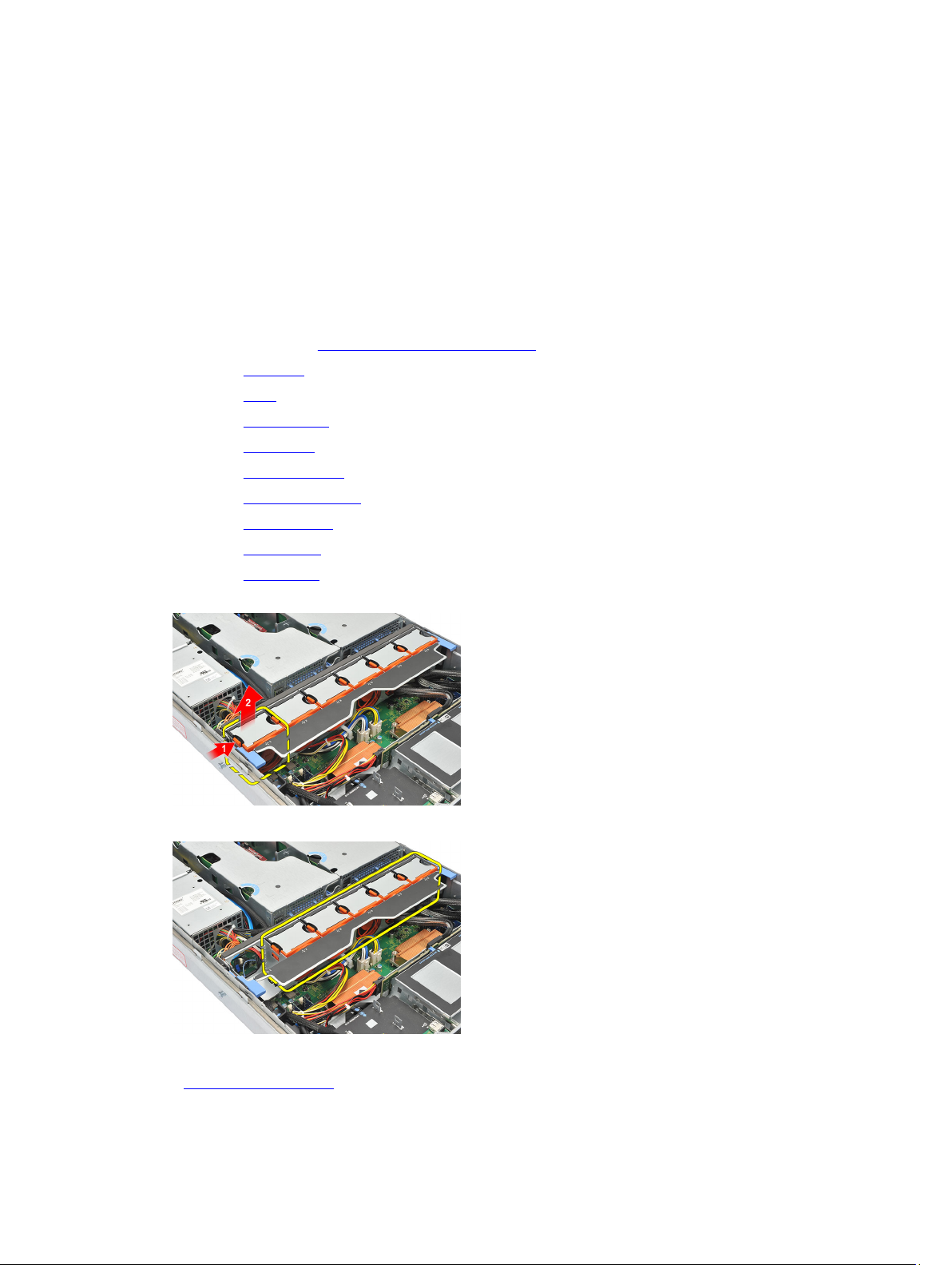
Removing the Expansion Card Cages
1. Follow the procedures in Before Working Inside Your Computer.
2. Remove the front bezel.
3. Remove the cover.
4. Remove the cooling shroud.
5. Remove the optical drive.
6. Remove the hard drive carrier.
7. Remove the hard-drive assembly.
8. Remove the SAS Backplane.
9. Remove the power supply.
10. Remove the control panel.
11. Remove the system fans.
12. Remove the removable fan bracket.
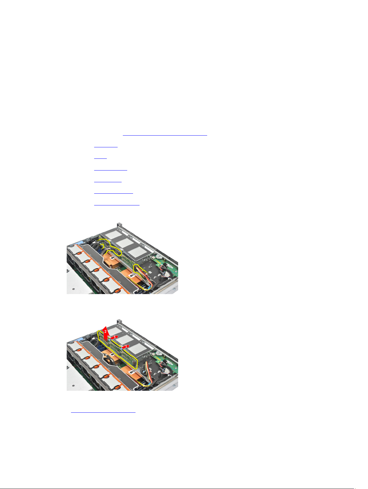
13. Release the clip securing the power cables.
13
14. Unthread the cables leading to the expansion card cage.
15. Carefully lift the expansion card cage.
33
Page 34

16. Flip the expansion cage over.
17. Disconnect cables leading to the expansion cards.
18. Carefully lift the outer expansion card-cage away from the computer.
19. Disconnect cables leading to the expansion card cage.
34
Page 35

20. Carefully lift the inner expansion card-cage away from the computer.
Related Links
Installing the Expansion Card Cages
Installing the Expansion Card Cages
1. Fix the inner expansion card cage in the computer.
2. Connect the cables leading to the expansion card cage.
3. Fix the outer expansion card cage in the computer.
4. Connect the cables leading to the expansion cards.
5. Flip the expansion cage.
6. Place and fix the expansion card cage.
7. Thread the cables leading to the expansion card cage.
8. Attach the clip securing the power cables.
9. Install the fan bracket.
10. Install the system fans.
11. Install the control panel.
12. Install the power supply.
13. Install the SAS backplane.
14. Install the hard drive assembly.
15. Install the hard-drive carrier.
16. Install the optical drive.
17. Install the cooling shroud.
18. Install the cover.
19. Install the front bezel.
20. Follow the procedures in After Working Inside Your Computer.
35
Page 36

Related Links
Removing the Expansion Card Cages
36
Page 37

Power Distribution Unit
Removing the Power Distribution Unit
1. Follow the procedures in Before Working Inside Your Computer.
2. Remove the front bezel.
3. Remove the cover.
4. Remove the cooling shroud.
5. Remove the optical drive.
6. Remove the hard drive carrier.
7. Remove the hard-drive assembly.
8. Remove the SAS Backplane.
9. Remove the power supply.
10. Remove the control panel.
11. Remove the system fans.
12. Remove the removable fan bracket.
13. Remove the expansion card cages.
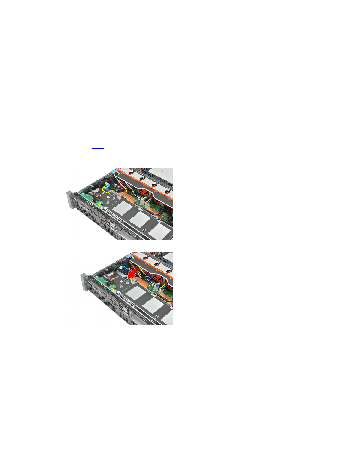
14. Release the cable clips leading to the Power Distribution Unit.
14
15. Disconnect CPU 1, CPU 2, SAS backplane and optical drive power connector.
16. Unroute CPU 1, CPU 2, SAS backplane and optical drive power cables.
37
Page 38

17. Remove the screws securing the Power Distribution Unit.
18. Carefully lift the Power Distribution Unit up and away from the computer.
Related Links
Installing the Power Distribution Unit
Installing the Power Distribution Unit
1. Place the power distribution unit on the computer.
2. Fix the screws securing the power distribution unit.
3. Route and place the CPU 1, CPU 2, SAS Backplane and optical driver power cables.
4. Connect CPU 1, CPU 2, SAS Backplane and optical driver power connectors.
5. Attach the cables leading to the power distribution unit.
6. Install the card cages.
7. Install the fan bracket.
8. Install the system fans.
9. Install the control panel.
38
Page 39

10. Install the power supply.
11. Install the SAS backplane.
12. Install the hard drive assembly.
13. Install the hard drive carrier.
14. Install the optical drive.
15. Install the cooling shroud.
16. Install the cover.
17. Install the front bezel.
18. Follow the procedures in After Working Inside Your Computer.
Related Links
Removing the Power Distribution Unit
39
Page 40

40
Page 41

Center Riser Board
Removing the Center Riser Board
1. Follow the procedures in Before Working Inside Your Computer.
2. Remove the front bezel.
3. Remove the cover.
4. Remove the cooling shroud.
5. Remove the optical drive.
6. Remove the hard drive carrier.
7. Remove the hard-drive assembly.
8. Remove the SAS Backplane.
9. Remove the power supply.
10. Remove the control panel.
11. Remove the system fans.
12. Remove the removable fan bracket.
13. Remove the expansion card cages.
14. Remove the power distribution unit.
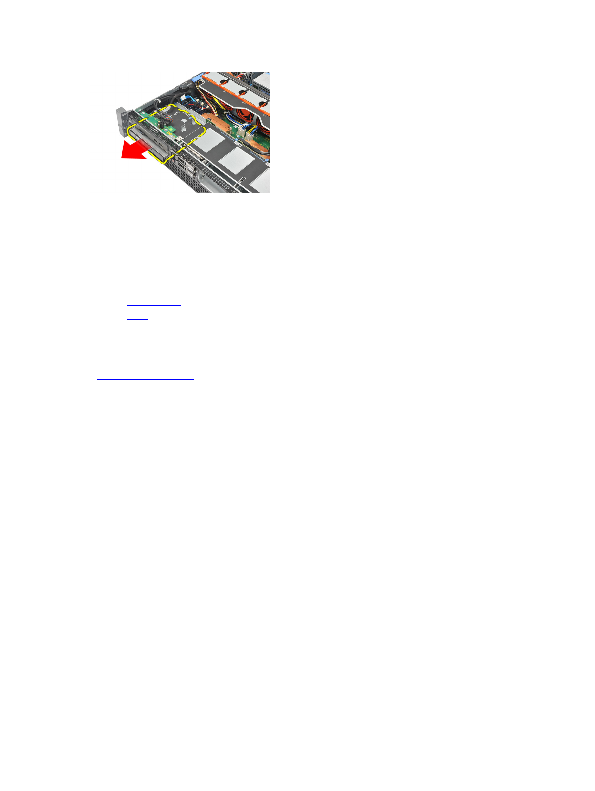
15. Lift the release tab upwards and gently slide the center riser board towards the right.
15
16. Lift the center riser board up and away from the computer.
41
Page 42

Related Links
Installing the Center Riser Board
Installing the Center Riser Board
1. Place the center riser board on the computer.
2. Slide the center riser board into place and press the release tab downwards.
3. Install the power distribution unit.
4. Install the card cages.
5. Install the fan bracket.
6. Install the system fans.
7. Install the control panel.
8. Install the power supply.
9. Install the SAS backplane.
10. Install the hard drive assembly.
11. Install the hard-drive carrier.
12. Install the optical drive.
13. Install the cooling shroud.
14. Install the cover.
15. Install the front bezel.
16. Follow the procedures in After Working Inside Your Computer.
Related Links
Removing the Center Riser Board
42
Page 43

CMOS Battery
Removing the CMOS Battery
1. Follow the procedures in Before Working Inside Your Computer.
2. Remove the front bezel.
3. Remove the cover.
4. Remove the cooling shroud.
5. Remove the optical drive.
6. Remove the hard drive carrier.
7. Remove the hard-drive assembly.
8. Remove the SAS Backplane.
9. Remove the power supply.
10. Remove the control panel.
11. Remove the system fans.
16
12. Remove the removable fan bracket.
13. Remove the expansion card cages.
14. Remove the power distribution unit.
15. Remove the center riser board.
16. Disconnect cables leading to the power distribution unit.
17. Press the coin-cell battery inward to allow the battery to pop up from the socket. (power distribution unit removed
for visibility purposes)
43
Page 44

18. Lift the coin-cell battery out of the system and properly dispose of the battery.
Related Links
Installing the CMOS Battery
Installing the CMOS Battery
1. Fix the coin-cell battery in the socket of the computer.
2. Connect the cables leading to the power distribution unit.
3. Install the center riser board.
4. Install the power distribution unit.
5. Install the card cages.
6. Install the fan bracket.
7. Install the system fans.
8. Install the control panel.
9. Install the power supply.
10. Install the SAS backplane.
11. Install the hard drive assembly.
12. Install the hard drive carrier.
13. Install the optical drive.
14. Install the cooling shroud.
15. Install the cover.
16. Install the front bezel.
17. Follow the procedures in After Working Inside Your Computer.
Related Links
Removing the CMOS Battery
44
Page 45

Video Card
Removing the Video Card
1. Follow the procedures in Before Working Inside Your Computer.
2. Remove the front bezel.
3. Remove the cover.
4. Remove the cooling shroud.
5. Remove the optical drive.
6. Remove the hard drive carrier.
7. Remove the hard-drive assembly.
8. Remove the SAS Backplane.
9. Remove the power supply.
10. Remove the control panel.
11. Remove the system fans.
17
12. Remove the removable fan bracket.
13. Remove the expansion card cages.
14. Remove the power distribution unit.
15. Remove the center riser board.
16. Remove the CMOS battery.
17. Press the release latch to unsecure the video card.
18. Press the release tab in the direction shown by (1) and carefully lift the video card up and away from the computer
as shown by direction marked (2).
45
Page 46

Related Links
Installing the Video Card
Installing the Video Card
1. Insert the video card in the slot provided until it clicks into place.
2. Press the release latch to secure the video card.
3. Install the CMOS battery.
4. Install the center riser board.
5. Install the power distribution unit.
6. Install the card cages.
7. Install the fan bracket.
8. Install the system fans.
9. Install the control panel.
10. Install the power supply.
11. Install the SAS backplane.
12. Install the hard drive assembly.
13. Install the hard drive carrier.
14. Install the optical drive.
15. Install the cooling shroud.
16. Install the cover.
17. Install the front bezel.
18. Follow the procedures in After Working Inside Your Computer.
Related Links
Removing the Video Card
46
Page 47

SAS Controller Card
Removing the SAS Controller Card
1. Follow the procedures in Before Working Inside Your Computer.
2. Remove the front bezel.
3. Remove the cover.
4. Remove the cooling shroud.
5. Remove the optical drive.
6. Remove the hard drive carrier.
7. Remove the hard-drive assembly.
8. Remove the SAS Backplane.
9. Remove the power supply.
10. Remove the control panel.
11. Remove the system fans.
18
12. Remove the removable fan bracket.
13. Remove the expansion card cages.
14. Remove the power distribution unit.
15. Remove the center riser board.
16. Remove the CMOS battery.
17. Remove the video card.
18. Press the release latch to unsecure the SAS Controller Card.
19. Carefully lift the SAS Controller Card up and away from the computer.
47
Page 48

Related Links
Installing the SAS Controller Card
Installing the SAS Controller Card
1. Place and insert the SAS controller card on the computer.
2. Replace the release latch to secure the SAS controller card.
3. Install the video card.
4. Install the CMOS battery.
5. Install the center riser board.
6. Install the power distribution unit.
7. Install the card cages.
8. Install the fan bracket.
9. Install the system fans.
10. Install the control panel.
11. Install the power supply.
12. Install the SAS backplane.
13. Install the hard drive assembly.
14. Install the hard drive carrier.
15. Install the optical drive.
16. Install the cooling shroud.
17. Install the cover.
18. Install the front bezel.
19. Follow the procedures in After Working Inside Your Computer.
20. To enable RAID, see RAID Configuration.
Related Links
Removing the SAS Controller Card
RAID Configuration
The Dell Precision R5500 supports RAID configurations 0, 1, 5 and, 10.
NOTE: For more information, see the SAS controller card user guide available on support.dell.com/manuals
NOTE: Due to the Dell Precision R5500 hard disk drive backplane architecture, only one hard disk drive controller
can be used at any one time.
48
Page 49

You must set your computer to RAID-enabled mode before starting any RAID configuration procedures. Use the
following steps to configure RAID on your computer:
1. Enter System setup, select Drives. Press <Enter>.
2. Select SATA operation, press <Enter>.
3. Select RAID On and press <Enter>, and then press <Esc>.
4. Select Save/Exit and press <Enter>. Exit the system setup and resume the boot process.
49
Page 50

50
Page 51

Remote Access Host Card
Removing the Remote Access Host Card
1. Follow the procedures in Before Working Inside Your Computer.
2. Remove the front bezel.
3. Remove the cover.
4. Remove the cooling shroud.
5. Remove the optical drive.
6. Remove the hard drive carrier.
7. Remove the hard-drive assembly.
8. Remove the SAS Backplane.
9. Remove the power supply.
10. Remove the control panel.
11. Remove the system fans.
12. Remove the removable fan bracket.
19
13. Remove the expansion card cages.
14. Remove the power distribution unit.
15. Remove the center riser board.
16. Remove the CMOS battery.
17. Remove the video card.
18. Remove the SAS controller card.
19. Press the release latch to unsecure the Remote Access Host Card.
20. Carefully lift the Remote Access Host Card up and away from the computer.
51
Page 52

Related Links
Installing the Remote Access Host Card
Installing the Remote Access Host Card
1. Place and insert the Remote Access Host Card in to the slot provided.
2. Replace the release latch to secure the Remote Access Host Card.
3. Install the SAS controller card.
4. Install the video card.
5. Install the CMOS battery.
6. Install the center riser board.
7. Install the power distribution unit.
8. Install the card cages.
9. Install the fan bracket.
10. Install the system fans.
11. Install the control panel.
12. Install the power supply.
13. Install the SAS backplane.
14. Install the hard drive assembly.
15. Install the hard drive carrier.
16. Install the optical drive.
17. Install the cooling shroud.
18. Install the cover.
19. Install the front bezel.
20. Follow the procedures in After Working Inside Your Computer.
Related Links
Removing the Remote Access Host Card
52
Page 53

20
Front Chassis Assembly
Removing the Front Chassis Assembly
1. Follow the procedures in Before Working Inside Your Computer.
2. Remove the front bezel.
3. Remove the cover.
4. Remove the cooling shroud.
5. Remove the optical drive.
6. Remove the hard drive carrier.
7. Remove the hard-drive assembly.
8. Remove the SAS Backplane.
9. Remove the power supply.
10. Remove the control panel.
11. Remove the system fans.
12. Remove the removable fan bracket.
13. Remove the expansion card cages.
14. Remove the power distribution unit.
15. Remove the center riser board.
16. Remove the CMOS battery.
17. Remove the video card.
18. Remove the SAS controller card.
19. Remove the remote access host card.
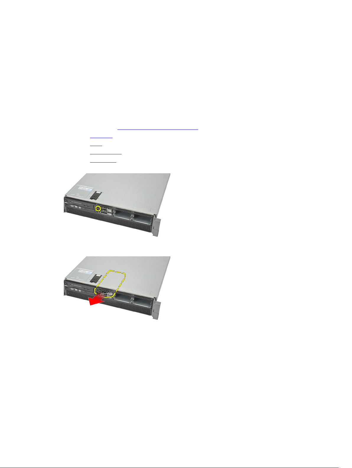
20. Press down on the two release tabs (marked as 1) and slide the front-chassis assembly towards the front of the
computer (marked as 2).
Related Links
Installing the Front Chassis Assembly
53
Page 54

Installing the Front-Chassis Assembly
1. Slide the front-chassis assembly towards the back of the computer until it clicks into place.
2. Install the remote access host card.
3. Install the SAS controller card.
4. Install the video card.
5. Install the CMOS battery.
6. Install the center riser board.
7. Install the power distribution unit.
8. Install the card cages.
9. Install the fan bracket.
10. Install the system fans.
11. Install the control panel.
12. Install the power supply.
13. Install the SAS backplane.
14. Install the hard drive assembly.
15. Install the hard drive carrier.
16. Install the optical drive.
17. Install the cooling shroud.
18. Install the cover.
19. Install the front bezel.
20. Follow the procedures in After Working Inside Your Computer.
Related Links
Removing the Front-Chassis Assembly
54
Page 55

Processor and Heat Sink
Removing the Processors and Heat Sink
1. Follow the procedures in Before Working Inside Your Computer.
2. Remove the front bezel.
3. Remove the cover.
4. Remove the cooling shroud.
5. Remove the optical drive.
6. Remove the hard drive carrier.
7. Remove the hard-drive assembly.
8. Remove the SAS Backplane.
9. Remove the power supply.
10. Remove the control panel.
11. Remove the system fans.
12. Remove the removable fan bracket.
13. Remove the expansion card cages.
14. Remove the power distribution unit.
15. Remove the center riser board.
16. Remove the CMOS battery.
17. Remove the video card.
18. Remove the SAS controller card.
19. Remove the remote access host card.
20. Remove the front chassis assembly.
21. Loosen the retaining screws on the heat sink.
21
22. Gently lift the heat sink off the processor and remove it from the computer.
55
Page 56

23. Position your thumb firmly over the processor socket-release lever. Release the lever from the locked position by
pushing down and pulling out from under the tab.
24. Rotate the lever 90 degrees upward until the processor is released from the socket. Rotate the processor shield
upward and remove it.
25. Carefully lift the processor out of the socket.
26. Repeat steps 21 to 25 for the second processor (if installed).
56
Page 57

Related Links
Installing the Processors and Heat Sink
Installing the Processors and Heat Sink
1. Place and insert the processor in the socket.
2. Press the processor shield downwards and cover the socket.
3. Press the processor socket-release lever downwards and fix it under the tab in the locked position.
4. Place the heat sink over the processor on the system board.
5. Tighten and secure the retaining screws on the heat sink.
6. Repeat steps 1 to 5 for the second processor.
7. Install the front chassis assembly.
8. Install the remote access host card.
9. Install the SAS controller card.
10. Install the video card.
11. Install the CMOS battery.
12. Install the center riser board.
13. Install the power distribution unit.
14. Install the card cages.
15. Install the fan bracket.
16. Install the system fans.
17. Install the control panel.
18. Install the power supply.
19. Install the SAS backplane.
20. Install the hard drive assembly.
21. Install the hard drive carrier.
22. Install the optical drive.
23. Install the cooling shroud.
24. Install the cover.
25. Install the front bezel.
26. Follow the procedures in After Working Inside Your Computer.
Related Links
Removing the Processors and Heat Sink
57
Page 58

58
Page 59

Memory
Removing the Memory
1. Follow the procedures in Before Working Inside Your Computer.
2. Remove the front bezel.
3. Remove the cover.
4. Remove the cooling shroud.
5. Remove the optical drive.
6. Remove the hard drive carrier.
7. Remove the hard-drive assembly.
8. Remove the SAS Backplane.
9. Remove the power supply.
10. Remove the control panel.
11. Remove the system fans.
12. Remove the removable fan bracket.
13. Remove the expansion card cages.
14. Remove the power distribution unit.
15. Remove the center riser board.
16. Remove the CMOS battery.
17. Remove the video card.
18. Remove the SAS controller card.
19. Remove the remote access host card.
20. Remove the front chassis assembly.
21. Remove the processor and heat sink.
22. Release the memory tabs.
22
23. Remove the memory module.
59
Page 60

24. Repeat steps 22 and 23 for the other memory modules.
Related Links
Installing the Memory
Installing the Memory
1. Insert the memory module in the slot.
2. Press back the memory tabs to lock it into place.
3. Repeat steps 1 and 2 for the remaining memory modules.
4. Install the processor and heat sink.
5. Install the front chassis assembly.
6. Install the remote access host card.
7. Install the SAS controller card.
8. Install the video card.
9. Install the CMOS battery.
10. Install the center riser board.
11. Install the power distribution unit.
12. Install the card cages.
13. Install the fan bracket.
14. Install the system fans.
15. Install the control panel.
16. Install the power supply.
17. Install the SAS backplane.
18. Install the hard drive assembly.
19. Install the hard drive carrier.
20. Install the optical drive.
60
Page 61

21. Install the cooling shroud.
22. Install the cover.
23. Install the front bezel.
24. Follow the procedures in After Working Inside Your Computer.
Related Links
Removing the Memory
61
Page 62

62
Page 63

System Board
Removing the System Board
1. Follow the procedures in Before Working Inside Your Computer.
2. Remove the front bezel.
3. Remove the cover.
4. Remove the cooling shroud.
5. Remove the optical drive.
6. Remove the hard drive carrier.
7. Remove the hard-drive assembly.
8. Remove the SAS Backplane.
9. Remove the power supply.
10. Remove the control panel.
11. Remove the system fans.
12. Remove the removable fan bracket.
13. Remove the expansion card cages.
14. Remove the power distribution unit.
15. Remove the center riser board.
16. Remove the CMOS battery.
17. Remove the video card.
18. Remove the SAS controller card.
19. Remove the remote access host card.
20. Remove the front chassis assembly.
21. Remove the processors and heat sink.
22. Remove the memory.
23. Disconnect all cables leading to the system board.
23
24. Lift the blue release tab and gently slide the system board towards the left.
63
Page 64

25. Carefully lift the system board up and away from the chassis.
Related Links
Installing the System Board
Installing the System Board
1. Place the system board on the chassis.
2. Gently slide the system board towards the back of the computer. Press the blue release tab.
3. Connect all cables to the system board.
4. Install the memory.
5. Install the processor and heat sink.
6. Install the front chassis assembly.
7. Install the remote access host card.
8. Install the SAS controller card.
9. Install the video card.
10. Install the CMOS battery.
11. Install the center riser board.
12. Install the power distribution unit.
13. Install the card cages.
14. Install the fan bracket.
15. Install the system fans.
16. Install the control panel.
17. Install the power supply.
18. Install the SAS backplane.
19. Install the hard drive assembly.
20. Install the hard drive carrier.
64
Page 65

21. Install the optical drive.
22. Install the cooling shroud.
23. Install the cover.
24. Install the front bezel.
25. Follow the procedures in After Working Inside Your Computer.
Related Links
Removing the System Board
65
Page 66

66
Page 67

24
System Setup
Boot Menu
As with previous workstation platforms, this computer includes a one-time boot menu. This feature gives users a quick
and convenient mechanism to bypass the System Setup-defined boot device order and boot directly to a specific device
(for example: floppy, CD-ROM, or hard drive). The boot menu enhancements introduced on previous platforms are as
follows:
• Easier access - Although the <Ctrl><Alt><F8> keystroke still exists and can be used to call up the menu, simply
press <F12> during system boot to access the menu.
• User prompting - Not only is the menu easy to access, but the user is prompted to use the keystroke on the BIOS
splash screen. The keystroke is no longer "hidden" from the user.
• Diagnostics options - The boot menu includes two diagnostic options, IDE Drive Diagnostics (90/90 Hard Drive
Diagnostics) and Boot to the Utility Partition. The benefit here is that the user does not have to remember the
<Ctrl><Alt><D> and <Ctrl><Alt><D> and <Ctrl><Alt><F10> keystrokes.
NOTE: Since the one-time boot menu only affects the current boot, it has the added benefit of not requiring the
technician to restore the customer's boot order after completing troubleshooting.
The computer has several keystroke options available during the POST process at the Dell Logo screen. These
keystrokes make several options available.
Keystroke Function Description
<F2> Enter System
Setup
<F12> or <Ctrl><Alt><F8> Enter Boot Menu One-time boot and diagnostics utility menu.
<F3> Network Boot Bypass the BIOS boot sequence and boot directly
Use System Setup to make changes to the userdefinable settings.
to the network.
67
Page 68

Timing Key Sequences
The keyboard is not the first device initialized by Setup. As a result, if you press a keystroke too early, you lock out the
keyboard. When this happens, a keyboard error message appears on the monitor, and you cannot restart the system
with the <Ctrl><Alt><Del> keys.
To avoid this scenario, wait until the keyboard is initialized before pressing the keystroke. There are two ways to know
that this has happened:
• The keyboard lights flash.
• The "F2=Setup" prompt appears in the top right-hand corner of the screen during boot.
The second method is good if the monitor is already warmed up. If it is not, the system often passes the window of
opportunity before the video signal is visible. If this is the case, rely on the first method—the keyboard lights—to know
the keyboard is initialized.
Dell Diagnostics
Factory-installed platforms include 32-bit system diagnostics on the installed utility partition. Access these diagnostics
using the <F12> keystroke during system boot and select Diagnostics.
After pressing the keystroke, the appropriate modules load and the PSA diagnostics run. If this passes, the standard Dell
Diagnostics main menu appears. When exiting the diagnostics, the system reboots and returns to the installed operating
system. Restarting the computer with the <Ctrl><Alt><Del> keystroke also returns the system to the normal boot
sequence as well.
Drives sent for service replacement do not have the utility partition and therefore do not have this capability. If pressed,
the keystroke is ignored on these drives.
NOTE: The utility partition is not protected from debug routines or the FDISK utility.
System Setup Options
NOTE: Depending on the computer and its installed devices, the items listed in this section may or may not appear.
• To make changes to the BIOS setup, select one of the below options, update the information and click Apply.
• To revert to the factory settings, click Load Defaults.
• To close the window, click Exit.
General
System Board Displays the following information:
• System Information: Displays BIOS Version, Service Tag, Express Service
Code, Asset Tag, Manufacture Date, and the Ownership Date.
• Memory Information: Displays Memory Installed, Memory Speed, Number of
Active Channels, Memory Technology, DIMM 1 Size, DIMM 2 Size, DIMM 3
Size, DIMM 4 Size, DIMM 5 Size, DIMM 6 Size, DIMM 7 Size , DIMM 8 Size ,
DIMM 9 Size ,DIMM 10 Size, DIMM 11 Size and DIMM 12 Size.
• Processor Information: Displays processor information for each CPU. The
following fields are common for CPU 1 and CPU 2: Processor Type, Processor
Speed, QPI Speed, Processor L2 Cache, Processor L3 Cache, Processor ID,
Microcode Version, Multi Core Capable, HT Capable and 64-Bit Technology.
68
Page 69

General
• Slot Information: Displays SLOT1, SLOT1, SLOT2, SLOT3, SLOT4, SLOT5,
SLOT6, and SLOT7.
Date/Time Displays current date and time settings. Changes to the system date and time take
effect immediately.
Boot Sequence Specifies the order in which the computer attempts to find an operating system from
the devices specified in this list.
• USB Floppy Drive
• #2300 ID00 LUN0 FUJITSU MBE2147RC
• #2300 ID01 LUN0 FUJITSU MBE2147RC
• CD/DVD/CD-RW Drive
• Onboard or USB CD-ROM Drive
• USB Device
Drives
Diskette Drive Determines how the BIOS configures floppy drives
• Disabled
• Enabled (default)
SATA Operation Configures the operating mode of the integrated hard-drive controller.
• RAID Autodetect / AHCI
• RAID Autodetect / ATA
• RAID On (default)
SMART Reporting Controls if hard drive errors for integrated drives are reported during start up.
Enable Smart Reporting — Disabled by default
Drives These fields let you enable or disable various drives in the computer:
• SATA-0
• SATA-1
• SATA-2
• SATA-3
• SATA-4
• SATA-5
System Configuration
Integrated NICs Enables or disables the integrated network card. You can set the integrated NIC to:
• Disable
• Enable (default)
• Enabled with PXE
USB Controller Enables or disables the integrated USB controller.
69
Page 70

System Configuration
• Disable
• Enable (Default)
• No Boot
Serial Port #1 Determines how the built-in serial port operates.
• Disable
• Auto (default)
• COM1
• COM3
Spread Spectrum Clocking Enables or disables spread spectrum clocking.
• Disable
• Enable (default)
Miscellaneous Devices Enables or disables various system devices.
• Front USB
• Rear USB
• Audio
Video
Primary Video Allows the user to specify the order in which the system assigns primary video controller
when two or more controllers are available.
• Option 1
• Option 2
Performance
Multi Core Support Specifies whether the computer will have one or all cores enabled.
Enable Multi Core Support — Enabled by default.
Hyper-Threading
Technology
Intel TurboBoost Enables or disables the Intel TurboBoost mode of the processor.
Intel SpeedStep Enables or disables the Intel SpeedStep mode of the processor.
C States Control Enables or disables additional processor sleep states.
Hardware Prefetcher When enabled, it will automatically prefetch data and code for the processor.
Adjacent Cache Line
Prefetch
Enables or disables the Hyper-Threading Technology.
Enable Hyper-Threading Technology — Disabled by default.
Enable Intel Turbo Boost Technology — Enabled by default
Enable Intel SpeedStep — Enabled by default
C States Control — Enabled by default
Enable Hardware Prefetcher — Enabled by default
When enabled, the processor will retrieve the current and subsequent cache line.
Enable Adjacent Cache Line Prefetch — Enabled by default
70
Page 71

Performance
Limit CPUID Value When enabled, limits the maximum value the processor Standard CPUID Function will
support.
Enable CPUID Limit — Disabled by default
Memory Node Interleaving Controls how many system memory distributed between physical processors is
configured and reported to the operating system.
• SMP (default)
• NUMA
Virtualization Support
Virtualization Specifies whether a Virtual Machine Monitor (VMM) can utilize the additional
hardware capabilities provided by Intel Virtualization Technology.
Enable Intel® Virtualization Technology - Enabled by default.
VT for Direct I/O Specifies whether a Virtual Machine Monitor (VMM) can utilize additional hardware
capabilities provided by Intel Virtualization technology for direct I/O.
Enable Intel® VT for Direct I/O - Disabled by default.
Security
Administrator Password Used to prohibit an unauthorized user from changing any configuration settings. Enter
the following details and click OK:
1. Old Password
2. New Password
3. Re-enter the new password
System Password Used to prohibit an unauthorized user from booting. Enter the following details and click
OK.
1. Enter the old password — If the password is not set, the 'Enter the old password'
field will not be set.
2. Enter the new password
3. Re-enter the password
Password Changes Controls the interaction between the system password and the administrator password.
Enable Password Changes (enabled by default)
TPM Security Controls whether the Trusted Platform Module (TPM) in the system is enabled and
visible to the operating system. When enabled, the BIOS will turn on the TPM during
POST so that it can be used by the operating system.
TPM Security (disabled by default)
When the option is enabled, the user can select between three options:
• Deactivate
• Activate
• Clear
CPU XD Support Enables or disables the Execute Disable mode of the processor.
71
Page 72

Security
Enable CPU XD Support — Enabled by default
OROM Protection Determines whether access to the Option ROM configurations are permitted during boot
(like CTRL+I or CRTL+P).
Enable OROM Protection — Enabled by default
Computrace(R) Activates or deactivates the BIOS module interface of the optional Computrace Service
from Absolute Software.
• Deactivate - Disabled by default.
• Disable
• Activate
Chassis Intrusion Controls the chassis intrusion feature. You can set this option to:
Clear Intrusion Warning — Enabled by default
Options available are enabled when the check box is selected.
• Disable
• Enable
• On-Silent — Enabled by default (if chassis intrusion is detected)
Power Management
AC Recovery Determines how the system responds when AC power is re-applied after a power loss.
You can set the AC Recovery to:
• Power Off (default)
• Power On
• Last State
Auto On Time Sets time to automatically turn on the computer. Time is kept in standard 12-hour
format (hour:minutes:seconds). Change the startup time by typing the values in the time
and AM/PM fields. The options available are:
• Disable (default)
• Every Day
• Weekdays
NOTE: This feature does not work if you turn off your computer using the switch on
a power strip or surge protector or if Auto Power is set to disabled.
Low Power Mode Determines how aggressive the computer is at conserving power while it is shutdown
or in Hibernate mode.
Enable Low Power Mode — Disabled by default
Remote Wake Up Determines if the system can be powered up remotely from Suspend, Hibernate, or Off.
• Disable
• Enable
• Enable with Boot to NIC
72
Page 73

Maintenance
Service Tag Displays the Service Tag of your computer.
Asset Tag Allows you to create a system asset tag if an asset tag is not already set.
System Management Controls the System Management mechanism.
• Disable (default)
• DASH/ASF 2.0
SERR Messages Controls the SERR message mechanism.
Enable SERR Messages — Enabled by default
POST Behavior
Fast Boot Allows speeding up the boot process by bypassing some compatibility steps.
Enable Fast Boot — Enabled by default
Numlock LED Specifies if Numlock feature should be on when your computer starts.
Enable Numlock LED — Enabled by default
POST Hotkeys Specifies if the sign-on screen displays a message stating the keystroke sequence
required to enter the Setup program or the QuickBoot feature.
Enable F12 = Boot menu — Enabled by default
Keyboard Errors Specifies if keyboard related errors are reported when the system boots
Enable Keyboard Error Detection
FX100 BIOS Access If enabled, allows a remote user to access BIOS Setup via FX100 Portal.
Enable FX100 BIOS Access — Enabled by default
System Logs
BIOS Events Displays the system event log and allows you to:
• Clear Log
• Mark All Entries
73
Page 74

74
Page 75

25
Troubleshooting
Diagnostic LEDs
NOTE: The diagnostic LEDs only serve as an indicator of the progress through the POST process. These LEDs do
not indicate the problem that caused the POST routine to stop.
The diagnostic LEDs are located on the front of the chassis next to the power button. These diagnostic LEDs are only
active and visible during the POST process. Once the operating system starts to load, they turn off and are no longer
visible.
The system now includes pre-POST and POST LEDs in an attempt to help pinpointing a possible problem with the system
easier and more accurate.
NOTE: The diagnostic lights will blink when the power button is amber or off, and will not blink when it is blue. This
has no other significance.
Light Pattern Problem Description Troubleshooting Steps
Diagnostic LEDs Power Button LED
The computer is either
turned off or is not receiving
power.
• Re-seat the power
cable in the power
connector at the
back of the
computer and the
electrical outlet.
• Bypass power
strips, power
extension cables,
and other power
protection devices
to verify that the
75
Page 76

Light Pattern Problem Description Troubleshooting Steps
Diagnostic LEDs Power Button LED
computer turns on
properly.
• Ensure that any
power strips being
used are plugged
into an electrical
outlet and are
turned on.
• Ensure that the
electrical outlet is
working by testing it
with another
device, such as a
lamp.
• Ensure that the
main power cable
and front panel
cable are securely
connected to the
system board.
A possible system board
failure has occurred.
A possible system board,
power supply, or peripheral
failure has occurred.
Unplug the computer. Allow
one minute for the power to
drain. Plug the computer
into a working electrical
outlet and press the power
button.
• Power off
computer, leaving
the computer
plugged in. Press
and hold the power
supply test button at
the rear of the
power supply unit. If
the LED next to the
switch illuminates,
the problem may be
with your system
board.
• If the LED next to
the switch does not
illuminate,
disconnect all
internal and
external
peripherals, and
press and hold the
power supply test
button. If it
illuminates, there
could be a problem
with a peripheral.
• If the LED still does
not illuminate,
remove the PSU
76
Page 77

Light Pattern Problem Description Troubleshooting Steps
Diagnostic LEDs Power Button LED
connections from
the system board,
then press and hold
the power supply
button. If it
illuminates, there
could be a problem
with the system
board.
• If the LED still does
not illuminate, the
problem is with the
power supply.
Memory modules are
detected, but a memory
power failure has occurred.
A possible CPU or system
board failure has occurred.
• If two or more
memory modules
are installed,
remove the
modules, then reinstall one module
and re-start the
computer. If the
computer starts
normally, continue
to install additional
memory modules
(one at a time) until
you have identified
a faulty module or
reinstalled all
modules without
error. If only one
memory module is
installed, try moving
it to a different
DIMM connector
and re-start the
computer.
• If available, install
verified working
memory of the same
type into your
computer.
Replace the CPU with a
known good CPU. If the
computer still fails to boot,
inspect the CPU socket for
damage.
BIOS may be corrupt or
missing.
The computer hardware is
operating normally but the
BIOS may be corrupt or
missing.
77
Page 78

Light Pattern Problem Description Troubleshooting Steps
Diagnostic LEDs Power Button LED
A possible system board
failure has occurred.
Power connector not
installed properly.
Possible peripheral card or
system board failure has
occurred.
A possible system board
failure has occurred.
Remove all peripheral cards
from the PCI and PCI-E slots
and re-start the computer. If
the computer boots, add the
peripheral cards back one
by one until you find the bad
one.
Re-seat the 2x2 power
connector from the power
supply unit.
Remove all peripheral cards
from the PCI and PCI-E slots
and re-start the computer. If
the computer boots, add the
peripheral cards back one
by one until you find the bad
one.
• Disconnect all
internal and
external
peripherals, and restart the computer.
If the computer
boots, add the
peripheral cards
back one by one
until you find the
bad one.
• If the problem
persists, the system
board is faulty.
A possible coin cell battery
failure has occurred.
The computer is in a normal
on
condition. The diagnostic
lights are not lit after the
computer successfully
boots to the operating
system.
A possible processor failure
has occurred.
78
Remove the coin cell
battery for one minute,
reinstall the battery, and
restart.
Ensure that the display is
connected and powered on.
Re-seat the processor.
Page 79

Light Pattern Problem Description Troubleshooting Steps
Diagnostic LEDs Power Button LED
Memory modules are
detected, but a memory
failure has occurred.
A possible graphics card
failure has occurred.
• If two or more
memory modules
are installed,
remove the modules
(see your service
manual), then reinstall one module
(see your service
manual) and restart the computer.
If the computer
starts normally,
continue to install
additional memory
modules (one at a
time) until you have
identified a faulty
module or
reinstalled all
modules without
error.
• If available, install
working memory of
the same type into
your computer.
• Ensure that the
display/monitor is
plugged into a
discrete graphic
card.
• Re-seat any
installed graphics
cards.
• If available, install a
working graphics
card into your
computer.
A possible floppy drive or
hard drive failure has
occurred.
A possible USB failure has
occurred
No memory modules are
detected.
Re-seat all power and data
cables.
Re-install all USB devices
and check all cable
connections.
• If two or more
memory modules
are installed,
remove the
modules, then
reinstall one module
and restart the
computer. If the
computer starts
normally, continue
79
Page 80

Light Pattern Problem Description Troubleshooting Steps
Diagnostic LEDs Power Button LED
to install additional
memory modules
(one at a time) until
you have identified
a faulty module or
reinstalled all
modules without
error.
• If available, install
working memory of
the same type into
your computer.
Memory modules are
detected, but a memory
configuration or
compatibility error has
occurred.
A possible expansion card
failure has occurred.
• Ensure that no
special
requirements for
memory module/
connector
placement exist.
• Ensure that the
memory you are
using is supported
by your computer.
• Determine if a
conflict exists by
removing an
expansion card (not
a graphics card)
and restarting the
computer.
• If the problem
persists, reinstall
the card you
removed, then
remove a different
card and restart the
computer.
• Repeat this process
for each expansion
card installed. If the
computer starts
normally,
troubleshoot the
last card removed
from the computer
for resource
conflicts.
A possible system board
resource and/or hardware
failure has occurred.
80
• Clear CMOS.
• Disconnect all
internal and
external
peripherals, and
restart the
computer. If the
computer boots,
Page 81

Light Pattern Problem Description Troubleshooting Steps
Diagnostic LEDs Power Button LED
add the peripheral
cards back one by
one until you find
the bad one.
• If the problem
persists, the system
board / system
board component is
faulty.
Some other failure has
occurred.
• Ensure that the
display/monitor is
plugged into a
discrete graphic
card.
• Ensure that all hard
drives and optical
drive cables are
properly connected
to the system board.
• If there is an error
message on the
screen identifying a
problem with a
device (such as the
floppy drive or hard
drive), check the
device to make sure
it is functioning
properly.
• If the operating
system is
attempting to boot
from a device (such
as the floppy drive
or optical drive),
check system setup
to ensure the boot
sequence is correct
for the devices
installed on your
computer.
Beep Codes
The computer can emit a series of beeps during start-up if the display cannot show errors or problems. These series of
beeps, called beep codes, identify various problems. The delay between each beep is 300 ms, the delay between each
set of beeps is 3 sec, and the beep sound lasts 300 ms. After each beep and each set of beeps, the BIOS should detect if
the user presses the power button. If so, BIOS will jump out from looping and execute the normal shutdown process and
power system.
Code 1-1-2
Cause Microprocessor register failure
Code 1-1-3
81
Page 82

Cause NVRAM
Code 1-1-4
Cause ROM BIOS checksum failure
Code 1-2-1
Cause Programmable interval timer
Code 1-2-2
Cause DMA initialization failure
Code 1-2-3
Cause DMA page register read/write failure
Code 1-3-1 through 2-4-4
Cause DIMMs not being properly identified or used
Code 3-1-1
Cause Slave DMA register failure
Code 3-1-2
Cause Master DMA register failure
Code 3-1-3
Cause Master interrupt mask register failure
Code 3-1-4
Cause Slave interrupt mask register failure
Code 3-2-2
Cause Interrupt vector loading failure
Code 3-2-4
Cause Keyboard Controller Test failure
Code 3-3-1
Cause NVRAM power loss
Code 3-3-2
Cause NVRAM configuration
Code 3-3-4
Cause Video Memory Test failure
Code 3-4-1
82
Page 83

Cause Screen initialization failure
Code 3-4-2
Cause Screen retrace failure
Code 3-4-3
Cause Search for video ROM failure
Code 4–2–1
Cause No time tick
Code 4–2–2
Cause Shutdown failure
Code 4–2–3
Cause Gate A20 failure
Code 4–2–4
Cause Unexpected interrupt in protected mode
Code 4–3–1
Cause Memory failure above address 0FFFFh
Code 4–3–3
Cause Timer-chip counter 2 failure
Code 4–3–4
Cause Time-of-day clock stopped
Code 4–4–1
Cause Serial or parallel port test failure
Code 4–4–2
Cause Failure to decompress code to shadowed memory
Code 4–4–3
Cause Math coprocessor test failure
Code 4–4–4
Cause Cache test failure
83
Page 84

Error Messages
Address mark not found
Description The BIOS found a faulty disk sector or could not find a particular disk sector.
Alert! Previous attempts at booting this system have failed at checkpoint [nnnn]. For help in resolving this problem, please note this checkpoint and contact Dell Technical Support.
Description The computer failed to complete the boot routine three consecutive times for the same error.
Contact Dell and report the checkpoint code (nnnn) to the support technician
Alert! Security override Jumper is installed.
Description The MFG_MODE jumper has been set and AMT Management features are disabled until it is
removed.
Attachment failed to respond
Description The floppy or hard drive controller cannot send data to the associated drive.
Bad command or file name
Description Ensure that you have spelled the command correctly, put spaces in the proper place, and used
the correct pathname.
Bad error-correction code (ECC) on disk read
Description The floppy or hard drive controller detected an uncorrectable read error.
Controller has failed
Description The hard drive or the associated controller is defective.
Data error
Description The floppy or hard drive cannot read the data. For the Windows operating system, run the
chkdsk utility to check the file structure of the floppy or hard drive. For any other operating
system, run the appropriate corresponding utility.
84
Page 85

Decreasing available memory
Description One or more memory modules may be faulty or improperly seated. Re-install the memory
modules and, if necessary, replace them.
Diskette drive 0 seek failure
Description A cable may be loose or the computer configuration information may not match the hardware
configuration.
Diskette read failure
Description The floppy disk may be defective or a cable may be loose. If the drive access light turns on, try
a different disk.
Diskette subsystem reset failed
Description The floppy drive controller may be faulty.
Gate A20 failure
Description One or more memory modules may be faulty or improperly seated. Reinstall the memory
modules and, if necessary, replace them.
General failure
Description The operating system is unable to carry out the command. This message is usually followed by
specific information—for example, Printer out of paper. Take the appropriate action to resolve
the problem.
Hard-disk drive configuration error
Description The hard drive failed initialization.
Hard-disk drive controller failure
Description The hard drive failed initialization.
85
Page 86

Hard-disk drive failure
Description The hard drive failed initialization.
Hard-disk drive read failure
Description The hard drive failed initialization.
Invalid configuration information-please run SETUP program
Description The computer configuration information does not match the hardware configuration.
Invalid Memory configuration, please populate DIMM1
Description DIMM1 slot does not recognize a memory module. The module should be re-seated or
installed.
Keyboard failure
Description A cable or connector may be loose, or the keyboard or keyboard/mouse controller may be
faulty.
Memory address line failure at address, read value expecting value
Description A memory module may be faulty or improperly seated. Reinstall the memory modules and, if
necessary, replace them.
Memory allocation error
Description The software you are attempting to run is conflicting with the operating system, another
program, or a utility.
Memory data line failure at address, read value expecting value
Description A memory module may be faulty or improperly seated. Reinstall the memory modules and, if
necessary, replace them.
86
Page 87

Memory double word logic failure at address, read value expecting value
Description A memory module may be faulty or improperly seated. Reinstall the memory modules and, if
necessary, replace them.
Memory odd/even logic failure at address, read value expecting value
Description A memory module may be faulty or improperly seated. Reinstall the memory modules and, if
necessary, replace them
Memory write/read failure at address, read value expecting value
Description A memory module may be faulty or improperly seated. Reinstall the memory modules and, if
necessary, replace them.
Memory size in CMOS invalid
Description The amount of memory recorded in the computer configuration information does not match the
memory installed in the computer.
Memory tests terminated by keystroke
Description A keystroke interrupted the memory test.
No boot device available
Description The computer cannot find the floppy disk or hard drive.
No boot sector on hard-disk drive
Description The computer configuration information in System Setup may be incorrect.
No timer tick interrupt
Description A chip on the system board might be malfunctioning.
87
Page 88

Non-system disk or disk error
Description The floppy disk in drive A does not have a bootable operating system installed on it. Either
replace the floppy disk with one that has a bootable operating system, or remove the floppy
disk from drive A and restart the computer.
Not a boot diskette
Description The operating system is trying to boot to a floppy disk that does not have a bootable operating
system installed on it. Insert a bootable floppy disk.
Plug and play configuration error
Description The computer encountered a problem while trying to configure one or more cards.
Read fault
Description The operating system cannot read from the floppy or hard drive, the computer could not find a
particular sector on the disk, or the requested sector is defective.
Requested sector not found
Description The operating system cannot read from the floppy or hard drive, the computer could not find a
particular sector on the disk, or the requested sector is defective.
Reset failed
Description The disk re-set operation failed.
Sector not found
Description The operating system cannot locate a sector on the floppy or hard drive.
Seek error
Description The operating system cannot find a specific track on the floppy disk or hard drive.
Shutdown failure
Description A chip on the system board might be malfunctioning.
88
Page 89

Time-of-day clock stopped
Description The battery might be dead.
Time-of-day not set-please run the System Setup program
Description The time or date stored in System Setup does not match the computer clock.
Timer chip counter 2 failed
Description A chip on the system board may be malfunctioning.
Unexpected interrupt in protected mode
Description The keyboard controller may be malfunctioning or a memory module may be loose.
WARNING: Dell's Disk Monitoring System has detected that drive [0/1] on the [primary/
secondary] EIDE controller is operating outside of normal specifications. It is advisable to
immediately back up your data and replace your hard drive by calling your support desk or
Dell.
Description During initial startup, the drive detected possible error conditions. When your computer
finishes booting, immediately back up your data and replace your hard drive (for installation
procedures, see "Adding and Removing Parts" for your computer type). If no replacement drive
is immediately available and the drive is not the only bootable drive, enter System Setup and
change the appropriate drive setting to None. Then remove the drive from the computer.
Write fault
Description The operating system cannot write to the floppy or hard drive.
Write fault on selected drive
Description The operating system cannot write to the floppy or hard drive.
X:\ is not accessible. The device is not ready
Description The floppy drive cannot read the disk. Insert a floppy disk into the drive and try again.
89
Page 90

90
Page 91

Specifications
Specifications
NOTE: Offerings may vary by region. The following specifications are only those required by law to ship with your
computer. For more information regarding the configuration of your computer, click Start → Help and Support and
select the option to view information about your computer.
Processor
Type Intel Xeon 5600 series CPUs
Cache
Instruction Cache 32 kB
Data Cache 32 kB
256 kB Mid-Level Cache per core
12 MB Last-Level Cache shared among all cores
System Information
Chipset Intel 5520 chipset
BIOS chip (NVRAM) 16 Mb SPI
26
Memory
Type DDR3, ECC only
Speed 1066 Mhz and 1333 MHz
Connectors twelve DIMM slots
Capacity 1 GB, 2 GB, 4 GB, 8 GB, and 16 GB
Minimum memory 1 GB
Maximum memory 192 GB
Video
Discrete Up to two PCI Express x16 graphics cards full-height, full-
length. Maximum of 450 W
Audio
Integrated Analog Devices ADI1984A
91
Page 92

Network
Integrated two Broadcom BCM5761 Gigabit Ethernet controllers with
support for teaming.
Expansion Bus
Bus type: PCI Express 2.0
PCI 2.3
SATA 1.0 and 2.0
USB 2.0
Bus speed: PCI: 133 MB/s
PCI Express:
• x4-slot bidirectional speed - 2 GB/s
• x8-slots bidirectional speed - 4 GB/s
• x16-slots bidirectional speed - 8 GB/s
SATA: 1.5 Gbps and 3.0 Gbps
USB: 480 Mbps high speed, 12 Mbps full speed, 1.2 Mbps
low speed
Card Slots
Outer Riser:
Slot 1 PCI Express x8/x16 electrical/mechanical, full-height, full-
length
Slot 2 PCI Express x16 electrical and mechanical, full-height,
full-length
Slot 3 N/A
Slot 4 PCI Express x16 electrical and mechanical, full-height,
full-length
Center Riser Option 1:
Slot 5 PCI 32b, 5V, full-height, full-length
Slot 6 PCI Express x16 electrical and mechanical, full-height,
full-length
Center Riser Option 2:
Slot 5 PCI Express x8/x16 electrical/mechanical, full-height, full-
length
Slot 6 PCI Express x16 electrical and mechanical, full-height,
full-length
Rear IO:
Slot 7 PCI Express x4/x8 electrical/mechanical, half-height, half-
length
92
Page 93

Drives
Externally accessible:
slimline SATA optical bays one
2.5 inch drive bays five SATA drives with onboard Intel controller or six SAS
drives with SAS/PERC 6iR cards
Internally accessible none
External connectors
Audio stereo out, Mic/Line In
Network two RJ-45
Serial one 9-pin connector, 16550C-compatible
USB front panel: 2; rear panel: 4
Video video card dependant
System ID Cable Management Arm (CMA) remote LED connector
Internal connectors
SATA two 36-pin Mini-SAS connectors; one seven-pin SATA
connector
Risers two 280-pin connectors
Front USB one 14-pin connector
Add-in HBA HDD LED one four-pin connector
System power one 24-pin connector
Power distribution board communication one six-pin connector
Front panel control one 28-pin connector
Systems fans six four-pin connectors
Host card remote power control one two-pin connector
CPU/Memory power two eight-pin connectors
Memory twelve 240-pin connectors (DDR3)
Rear IO:
PCI Express one 98-pin connector (x8)
Serial one 14-pin connector
Risers:
Outer Riser
PCI Express three 164-pin connectors (x16)
Center Riser Option 1:
PCI one 120-pin connector (32 bit)
PCI Express one 164-pin connectors (x16)
93
Page 94

Internal connectors
Center Riser Option 2
PCI Express two 164-pin connectors (x16)
Front IO:
Front USB one 14-pin connector
Internal USB one four-pin connector
Front panel control one 28-pin connector
HDD Back Panel :
SATA two 36-pin Mini-SAS connectors; six 29-pin HDD
connectors
Power one 14–pin connector
Controls and Lights
Power button light: off — system is off or unplugged.
solid blue light — computer is operating normally.
blinking blue light — computer is in stand by.
solid amber light — the computer does not start, indicating a problem with the
system board or power supply.
blinking amber light — indicates a problem has occurred with the system board.
System ID button and light blue light — flashes (front and back of chassis) when the button is pressed.
Press the button again to turn it off.
Drive activity light blue light — blinking blue light indicates that the computer is reading data from,
or writing data to the hard drive.
Network link integrity lights (front): blue light — A good connection exists between the network and the computer.
off (no light) — The computer is not detecting a physical connection to the
network.
Network link integrity lights (rear): green light — A good connection at 10 Mbs exists between the network and the
computer
orange light — A good connection at 100 Mbs exists between the network and
the computer.
amber light — A good connection at 1000 Mbs exists between the network and
the computer.
Network activity lights amber light — flashes when there is network activity on the connection.
Diagnostic lights: off — computer is off or has completed POST.
amber/blinking light — see the service manual for specific diagnostic codes.
Power
Coin-cell battery 3 V CR2032 lithium coin cell
Voltage 100 V to 240 V, 12.00 A to 6.00 A, 50 Hz to 60 Hz
94
Page 95

Power
Wattage 1023 W on 100 VAC to 120 VAC, 1100 W on 200 VAC to
240 VAC
Maximum heat dissipation 4774 BTU/hr
NOTE: Heat dissipation is calculated by using the power supply wattage rating.
NOTE: See the safety information that shipped with your computer for important voltage setting information.
Physical
Height 86.30 mm (3.40 inches)
Width 440.60 mm (17.35 inches)
Depth
with front bezel 792.70 mm (31.21 inches)
without front bezel 753.60 mm (29.67 inches)
Weight (Minimum)
with front bezel 23.91 kg (52.6 lb)
without front bezel 23.52 kg (51.7 lb)
Environmental
Temperature:
Operating 10 °C to 35 °C (50 °F to 95 °F)
Storage -40 °C to 65 °C (-40 °F to 149 °F)
Relative humidity (maximum):
Operating 10% to 90% (noncondensing)
Storage 5% to 95% (noncondensing)
Maximum vibration:
Operating 5 Hz to 350 Hz at 0.0002 G2/Hz
Storage 5 Hz to 500 Hz at 0.001 to 0.01 G2/Hz
Maximum shock:
Operating 40 G +/- 5% with pulse duration of 2 msec +/- 10%
(equivalent to 20 in/sec [51 cm/sec])
Storage 105 G +/- 5% with pulse duration of 2 msec +/- 10%
(equivalent to 50 in/sec [127 cm/sec])
Altitude:
Operating –15.2 m to 3048 m (–50 ft to 10,000 ft)
Storage –15.2 m to 10,668 m (–50 ft to 35,000 ft)
Airborne contaminant level G1 or lower as defined by ISA-S71.04–1985
95
Page 96

96
Page 97

27
Contacting Dell
Contacting Dell
NOTE: If you do not have an active Internet connection, you can find contact information on your purchase invoice,
packing slip, bill, or Dell product catalog.
Dell provides several online and telephone-based support and service options. Availability varies by country and
product, and some services may not be available in your area. To contact Dell for sales, technical support, or customer
service issues:
1. Visit support.dell.com.
2. Select your support category.
3. If you are not a U.S. customer, select your country code at the bottom of the page, or select All to see more
choices.
4. Select the appropriate service or support link based on your need.
97
 Loading...