

Page 1

Dell Precision™ Workstation 690
Quick Reference Guide
Model DCD0
www.dell.com | support.dell.com
Page 2

Notes, Notices, and Cautions
NOTE: A NOTE indicates important information that helps you make better use of your computer.
NOTICE: A NOTICE indicates either potential damage to hardware or loss of data and tells you how to avoid the
problem.
CAUTION: A CAUTION indicates a potential for property damage, personal injury, or death.
Abbreviations and Acronyms
For a complete list of abbreviations and acronyms, see Glossary in your
User’s Guide
.
If you purchased a Dell™ n Series computer, any references in this document to Microsoft
operating systems are not applicable.
____________________
®
Windows®
Information in this document is subject to change without notice.
© 2006 Dell Inc. All rights reserved.
Reproduction in any manner whatsoever without the written permission of Dell Inc. is strictly forbidden.
Trademarks used in this text: Dell, the DELL logo and Dell Precision are trademarks of Dell Inc.; Intel, Xeon, and Pentium are registered
trademarks of Intel Corporation; Microsoft and Windows are registered trademarks of Microsoft Corporation.
Other trademarks and trade names may be used in this document to refer to either the entities claiming the marks and names or their products.
Dell Inc. disclaims any proprietary interest in trademarks and trade names other than its own.
Model DCD0
January 2006 P/N MD490 Rev. A00
Page 3

Contents
Finding Information . . . . . . . . . . . . . . . . . . . . . . . . . . . . . . . . 5
Setting Up Your Computer
About Your Computer
Front View
Back View
. . . . . . . . . . . . . . . . . . . . . . . . . . . . . . . . . . 15
. . . . . . . . . . . . . . . . . . . . . . . . . . . . . . . . . . 18
Back Panel Connectors
Inside View
. . . . . . . . . . . . . . . . . . . . . . . . . . . . . . . . . 21
System Board Components
Locating Your User’s Guide
Removing the Computer Cover
Computer Stand
. . . . . . . . . . . . . . . . . . . . . . . . . . . . . . . . . 26
Attaching the Computer Stand
Removing the Computer Stand
Caring for Your Computer
Solving Problems
Troubleshooting Tips
. . . . . . . . . . . . . . . . . . . . . . . . . . . . . 9
. . . . . . . . . . . . . . . . . . . . . . . . . . . . . . . 14
. . . . . . . . . . . . . . . . . . . . . . . . . . . 19
. . . . . . . . . . . . . . . . . . . . . . . . . 22
. . . . . . . . . . . . . . . . . . . . . . . . . . . 24
. . . . . . . . . . . . . . . . . . . . . . . . . . 24
. . . . . . . . . . . . . . . . . . . . . . . 27
. . . . . . . . . . . . . . . . . . . . . . . 28
. . . . . . . . . . . . . . . . . . . . . . . . . . . . 29
. . . . . . . . . . . . . . . . . . . . . . . . . . . . . . . . 29
. . . . . . . . . . . . . . . . . . . . . . . . . . . . 29
Resolving Software and Hardware Incompatibilities
®
Using Microsoft
Windows® XP System Restore . . . . . . . . . . . . . 30
Using the Last Known Good Configuration
Dell Diagnostics
Before you start testing
. . . . . . . . . . . . . . . . . . . . . . . . . . . . . . . 32
. . . . . . . . . . . . . . . . . . . . . . . . . . . 33
. . . . . . . . . . . 29
. . . . . . . . . . . . . . . . . 31
Beep Codes
. . . . . . . . . . . . . . . . . . . . . . . . . . . . . . . . . . . . 33
Error Messages
Diagnostic Lights
. . . . . . . . . . . . . . . . . . . . . . . . . . . . . . . . . 35
Diagnostic Light Codes Before POST
Diagnostic Light Codes During POST
Frequently Asked Questions
Index . . . . . . . . . . . . . . . . . . . . . . . . . . . . . . . . . . . . . . . . . 43
. . . . . . . . . . . . . . . . . . . . . . . . . . . . . . . 35
. . . . . . . . . . . . . . . . . . . . 35
. . . . . . . . . . . . . . . . . . . . 37
. . . . . . . . . . . . . . . . . . . . . . . . . . . 41
Contents 3
Page 4

4 Contents
Page 5
Finding Information
NOTE: Some features or media may be optional and may not ship with your computer. Some features or media
may not be available in certain countries.
NOTE: Additional information may ship with your computer.
What Are You Looking For? Find It Here
• A diagnostic program for my computer
• Drivers for my computer
• My computer documentation
• My device documentation
• Desktop System Software (DSS)
• How to set up my computer
• How to care for my computer
• Basic troubleshooting information
• How to run the Dell™ Diagnostics
• Error codes and diagnostic lights
• How to remove and install parts
• How to open my computer cover
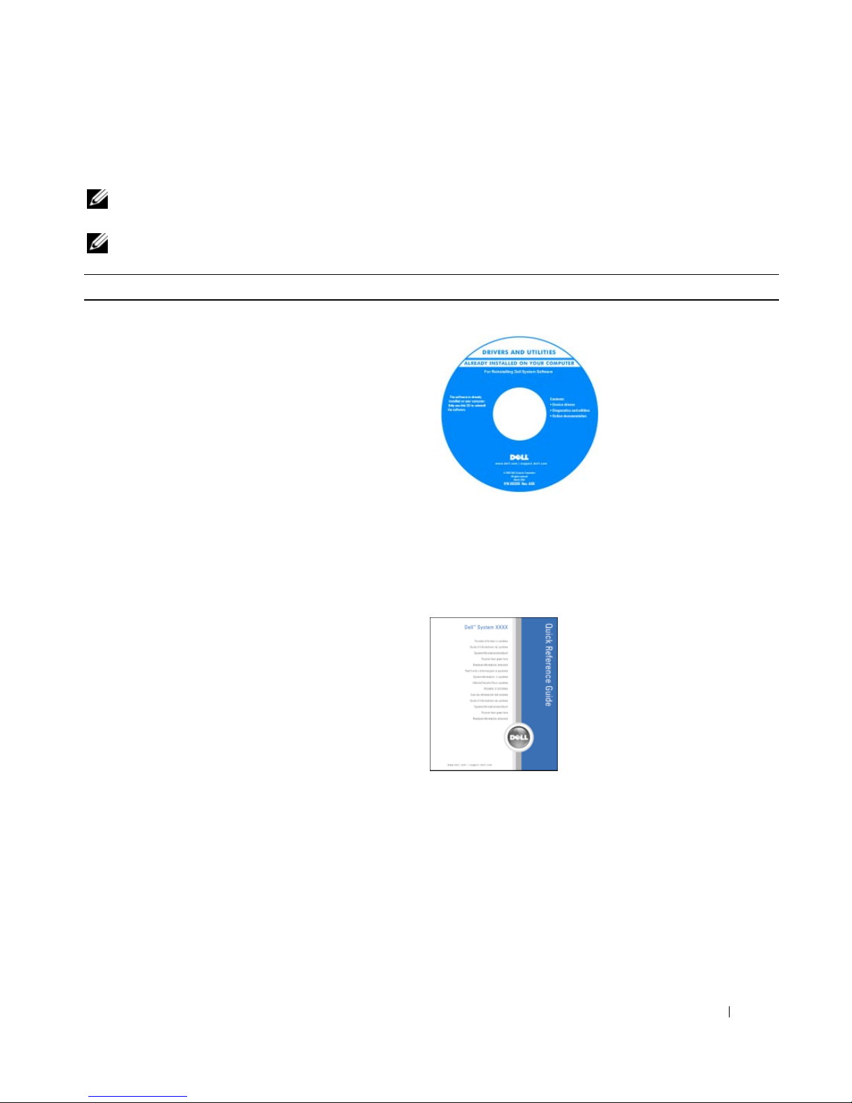
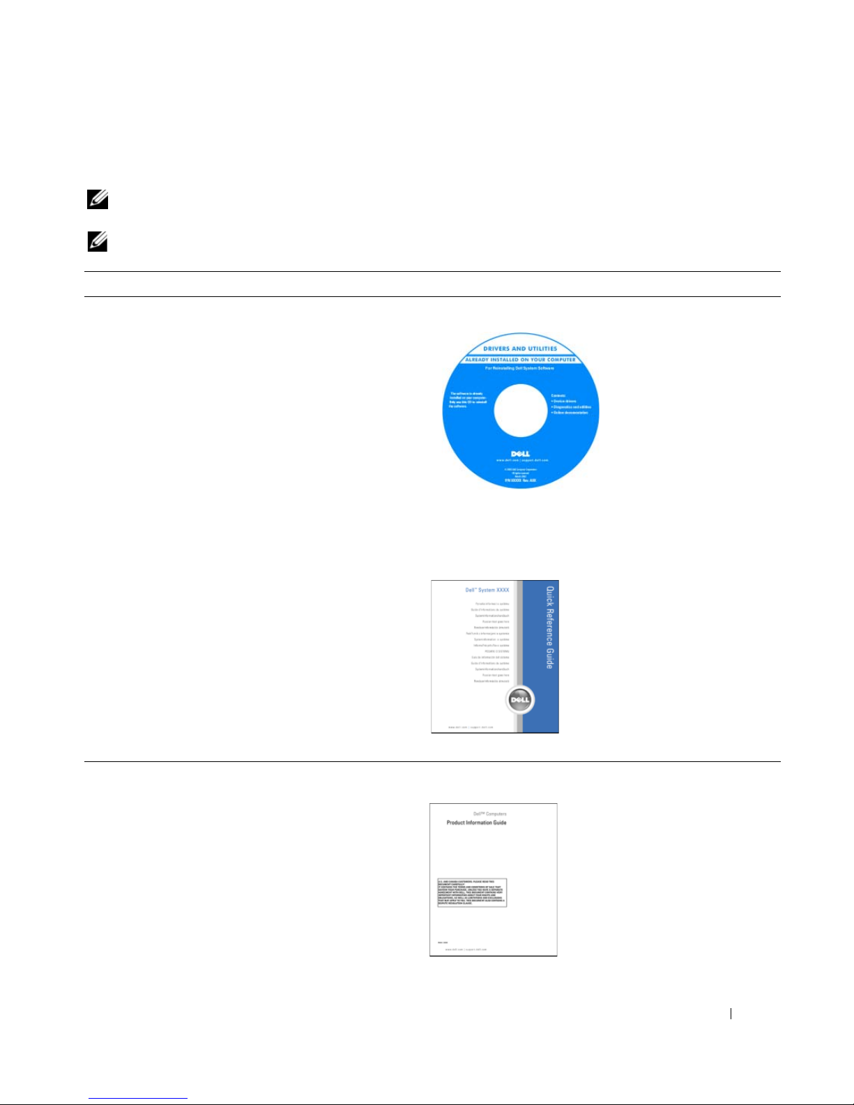
Drivers and Utilities CD (also known as Resource CD)
Documentation and
drivers are already
installed on your
computer. You can use the
CD to reinstall drivers, run
the Dell Diagnostics or
access your
documentation. Readme
files may be included on
your CD to provide last-
minute updates about
technical changes to your computer or advanced technicalreference material for technicians or experienced users.
NOTE: Drivers and documentation updates can be found at
support.dell.com.
Quick Reference Guide
NOTE: This document is available as a PDF at
support.dell.com.
Quick Reference Guide 5
Page 6
What Are You Looking For? Find It Here
• Warranty information
• Terms and Conditions (U.S. only)
• Safety instructions
• Regulatory information
• Ergonomics information
• End User License Agreement
• How to remove and replace parts
• Specifications
• How to configure system settings
• How to troubleshoot and solve problems
• Service Tag and Express Service Code
• Microsoft Windows License Label
Dell™ Product Information Guide
User’s Guide
Microsoft
1
2
®
Windows® XP Help and Support Center
Click the Start button and click
Help and Support
Click User’s and system guides and click
User’s Guide
The User’s Guide is also available on the Drivers and
Utilities CD.
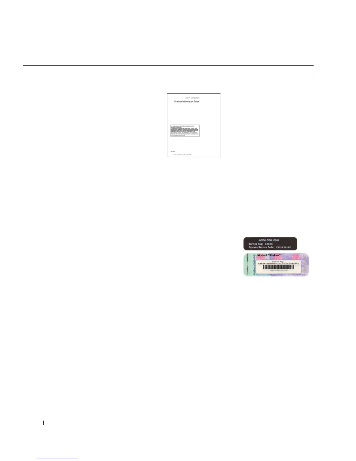
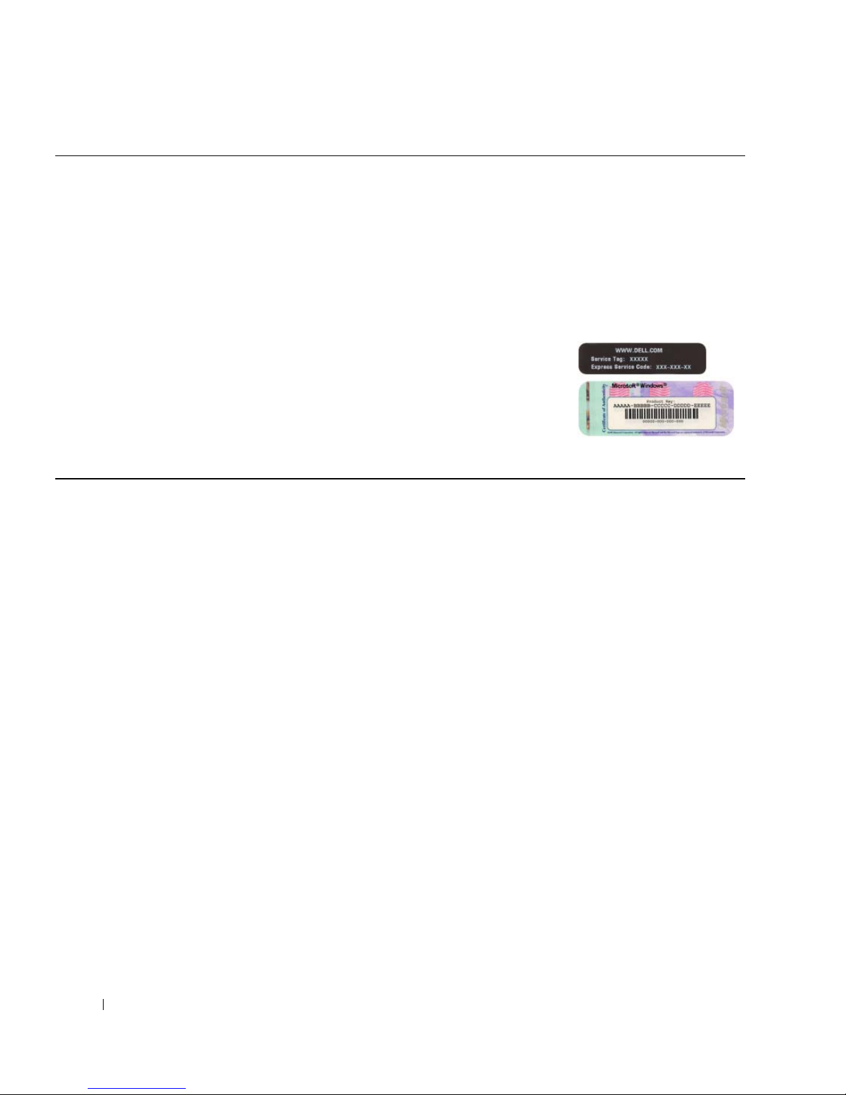
Service Tag and Microsoft® Windows® License
These labels are located on your computer.
• Use the Service Tag to
identify your computer
when you use
support.dell.com
or
contact technical
support.
• Enter the Express
Service Code to direct your call when contacting technical
support.
6 Quick Reference Guide
Page 7

What Are You Looking For? Find It Here
• Solutions — Troubleshooting hints and tips, articles
from technicians, and online courses, frequently asked
questions
• Community — Online discussion with other Dell
customers
• Upgrades — Upgrade information for components, such
as memory, the hard drive, and the operating system
• Customer Care — Contact information, service call and
order status, warranty, and repair information
• Service and support — Service call status and support
history, service contract, online discussions with
technical support
• Reference — Computer documentation, details on my
computer configuration, product specifications, and
white papers
• Downloads — Certified drivers, patches, and software
updates
• Desktop System Software (DSS)— If you reinstall the
operating system for your computer, you should reinstall
the DSS utility prior to installing any of the drivers. DSS
provides critical updates for your operating system and
support for Dell™ 3.5-inch USB floppy drives, optical
drives, and USB devices. DSS is necessary for correct
operation of your Dell computer. The software
automatically detects your computer and operating
system and installs the updates appropriate for your
configuration.
Dell Support Website — support.dell.com
NOTE: Select your region or business segment to view the
appropriate support site.
NOTE: Corporate, government, and education customers
can also use the customized Dell Premier support website at
premier.support.dell.com. The website may not be available
in all regions.
• How to use Windows XP
• How to work with programs and files
• Documentation for devices (such as modem)
Windows Help and Support Center
1
Click the
2
Type a word or phrase that describes your problem and
Start
button and click
Help and Support
click the arrow icon.
3
Click the topic that describes your problem.
4
Follow the instructions on the screen.
Quick Reference Guide 7
.
Page 8

What Are You Looking For? Find It Here
• How to reinstall my operating system
• How to use Linux
• E-mail discussions with users of Dell Precision™
products and the Linux operating system
• Additional information regarding Linux and my Dell
Precision computer
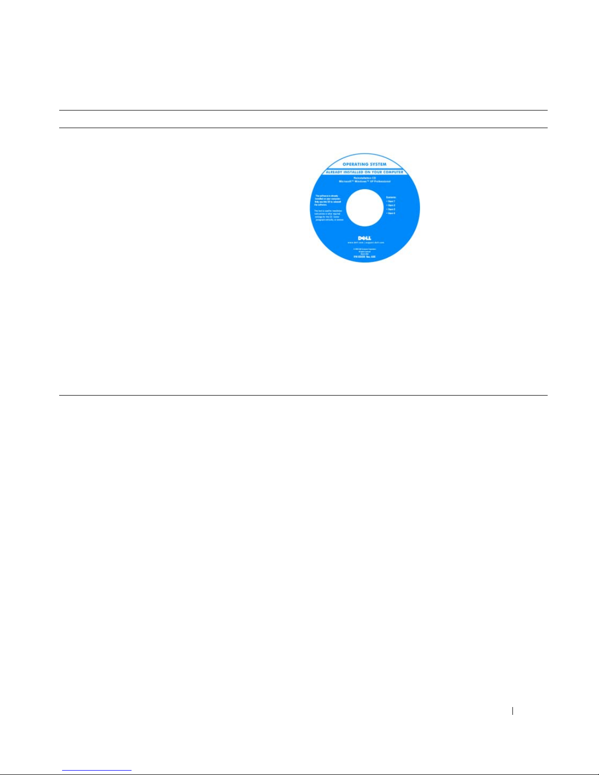
Operating System CD
The operating system is
already installed on your
computer. To reinstall your
operating system, use the
Operating System CD. See
your User’s Guide for
instructions. After you
reinstall your operating
system, use the Drivers and
Utilities CD (ResourceCD)
to reinstall drivers for the
devices that came with your computer. Your operating
system product key label is located on your computer.
NOTE: The color of your CD varies based on the operating
system you ordered.
NOTE: The Operating System CD may be optional and may
not ship with your computer.
Dell Supported Linux Sites
• Linux.dell.com
• Lists.us.dell.com/mailman/listinfo/linux-precision
8 Quick Reference Guide
Page 9
Setting Up Your Computer
CAUTION: Before you begin any of the procedures in this section, follow the safety instructions in the Product
Information Guide.
You must complete all steps to properly set up your computer.
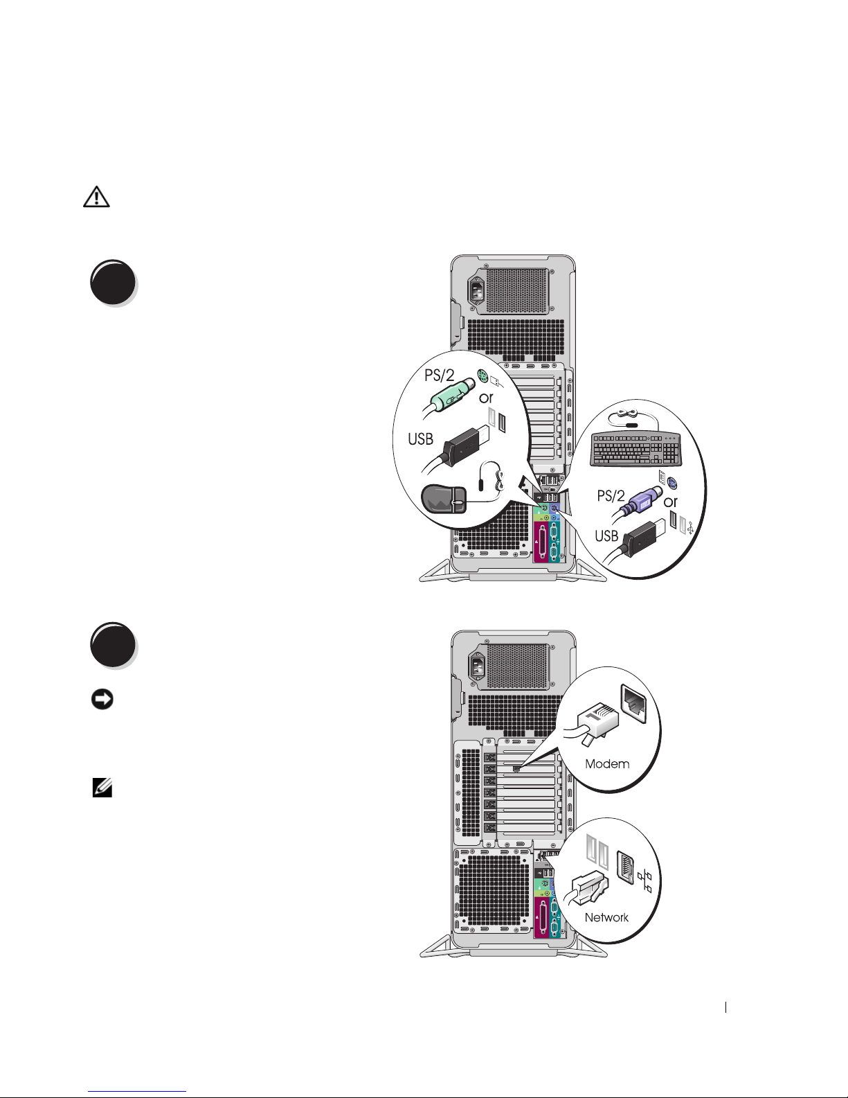
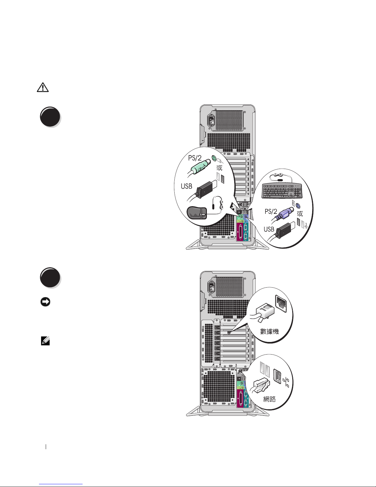
1
2
Connect the keyboard and the mouse.
Connect the modem or the network cable.
NOTICE: Do not connect a modem cable to the
network adapter. Voltage from telephone
communications can damage the network adapter.
NOTE: If your computer has a network card installed,
connect the network cable to the card.
Quick Reference Guide 9
Page 10
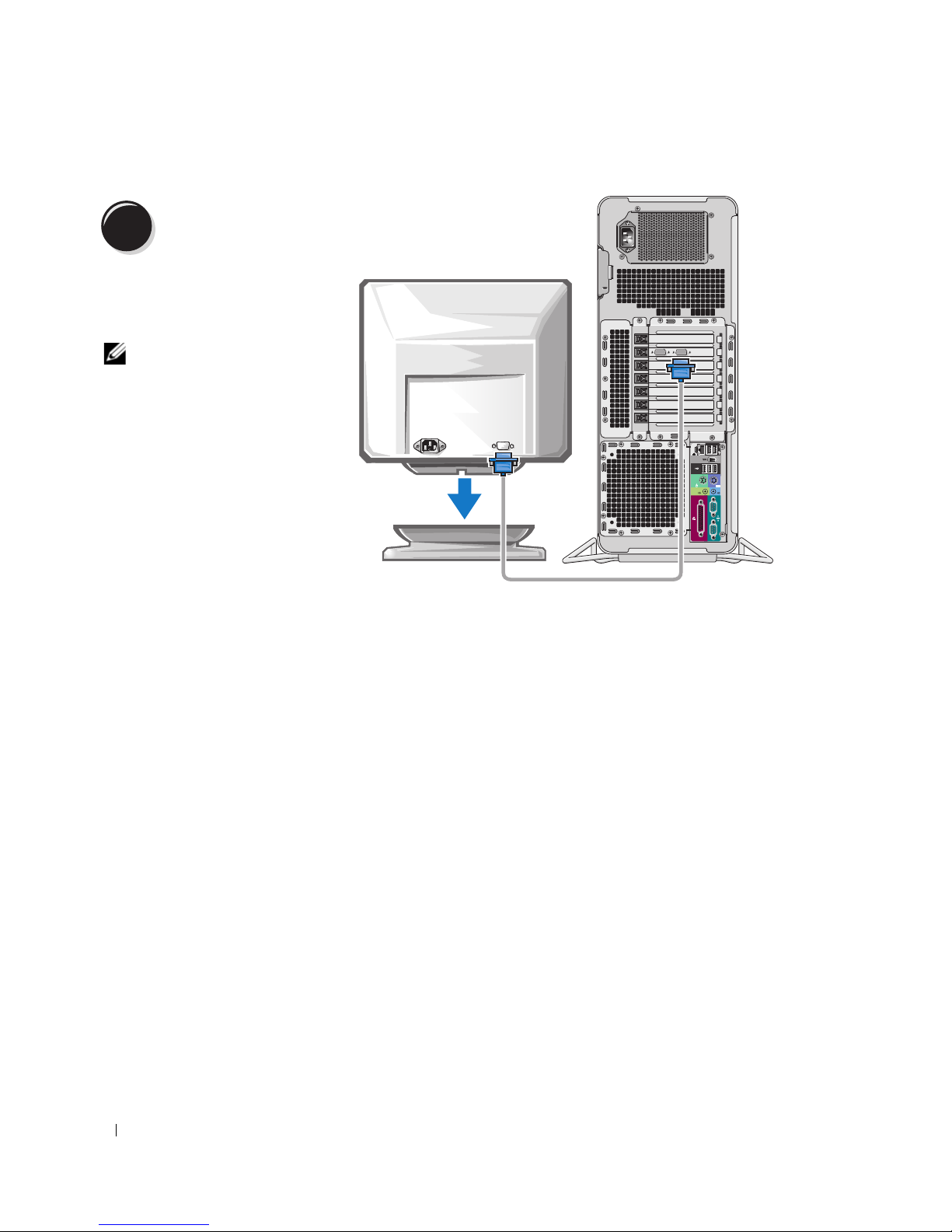
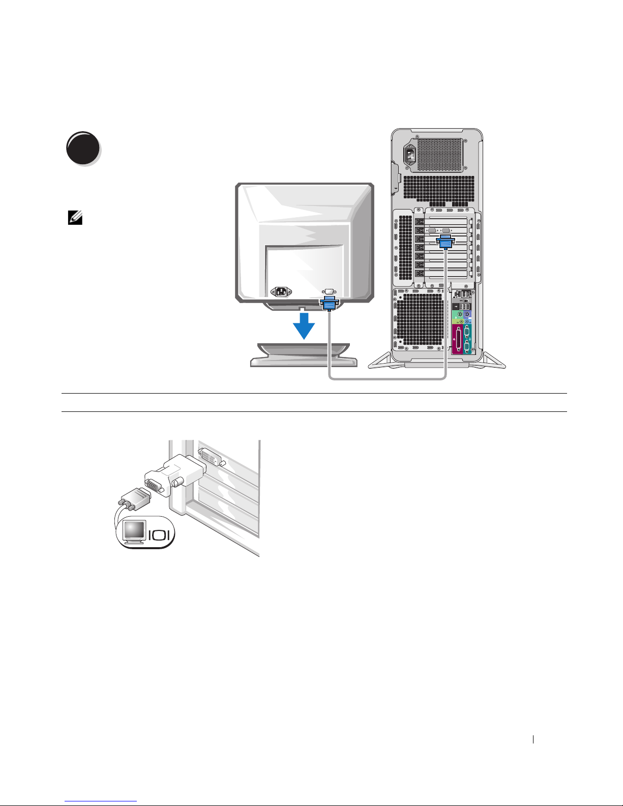
3
Depending on your graphics
card, you can connect your
monitor in various ways.
Connect the monitor.
NOTE: You may need to use
the provided adapter or
cable to connect your
monitor to the computer.
10 Quick Reference Guide
Page 11

For single- and dual-monitor capable cards with a single connector
One VGA adapter:
VGA
Use the VGA adapter when you have a single-monitor
graphics card and you want to connect your computer to a
VGA monitor.
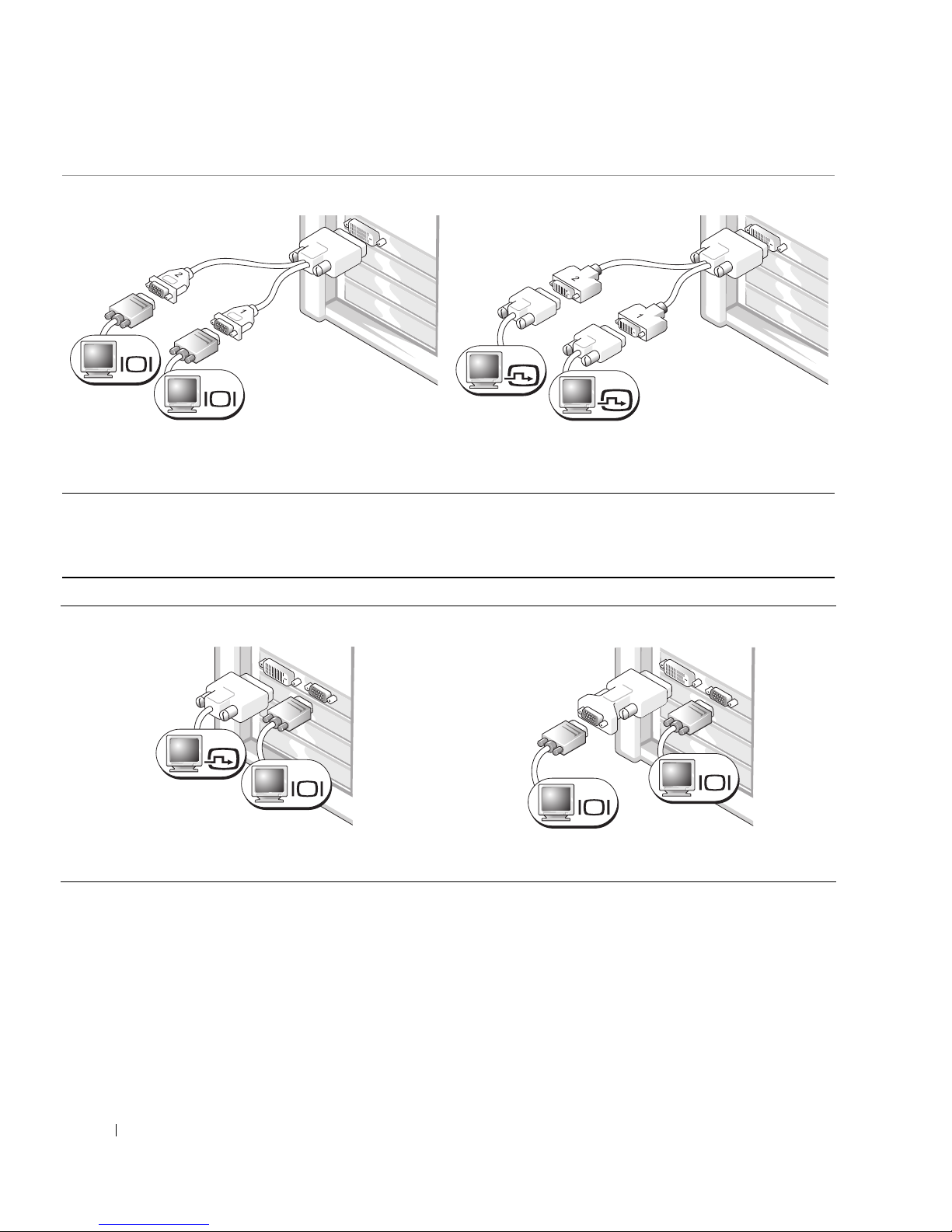
Dual VGA Y cable adapter:
VGA
VGA
Use the appropriate Y cable when your graphics card has a
single connector and you want to connect your computer
to one or two VGA monitors.
Dual DVI Y cable adapter:
DVI
DVI
Use the appropriate Y cable when your graphics card has a
single connector and you want to connect your computer
to one or two DVI monitors.
The dual-monitor cable is color-coded; the blue connector is for the primary monitor, and the black
connector is for the second monitor. To enable dual-monitor support, both monitors must be attached to
the computer when you start the computer.
Quick Reference Guide 11
Page 12
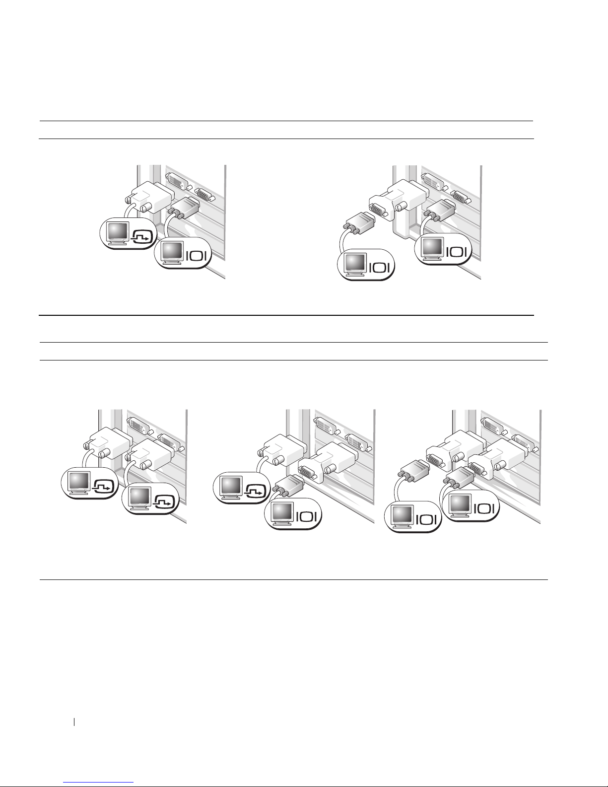
For dual-monitor capable cards with one DVI connector and one VGA connector
One DVI connector and one VGA connector:
DVI
VGA
Use the appropriate connector(s) when you want to
connect your computer to one or two monitors.
For dual-monitor capable cards with two DVI connectors
Two DVI connectors:
Two DVI connectors with one VGA
adapter:
Two VGA connectors with one VGA adapter:
VGA
VGA
Use the VGA adapter when you want to connect your
computer to two VGA monitors.
Two DVI connectors with two VGA
adapters:
DVI
DVI
Use the DVI connectors to connect
your computer to one or two DVI
monitors.
12 Quick Reference Guide
DVI
VGA
Use the VGA adapter to connect a
VGA monitor to one of the DVI
connectors on your computer
VGA
VGA
Use two VGA adapters to connect two
VGA monitors to the DVI connectors
on your computer.
Page 13
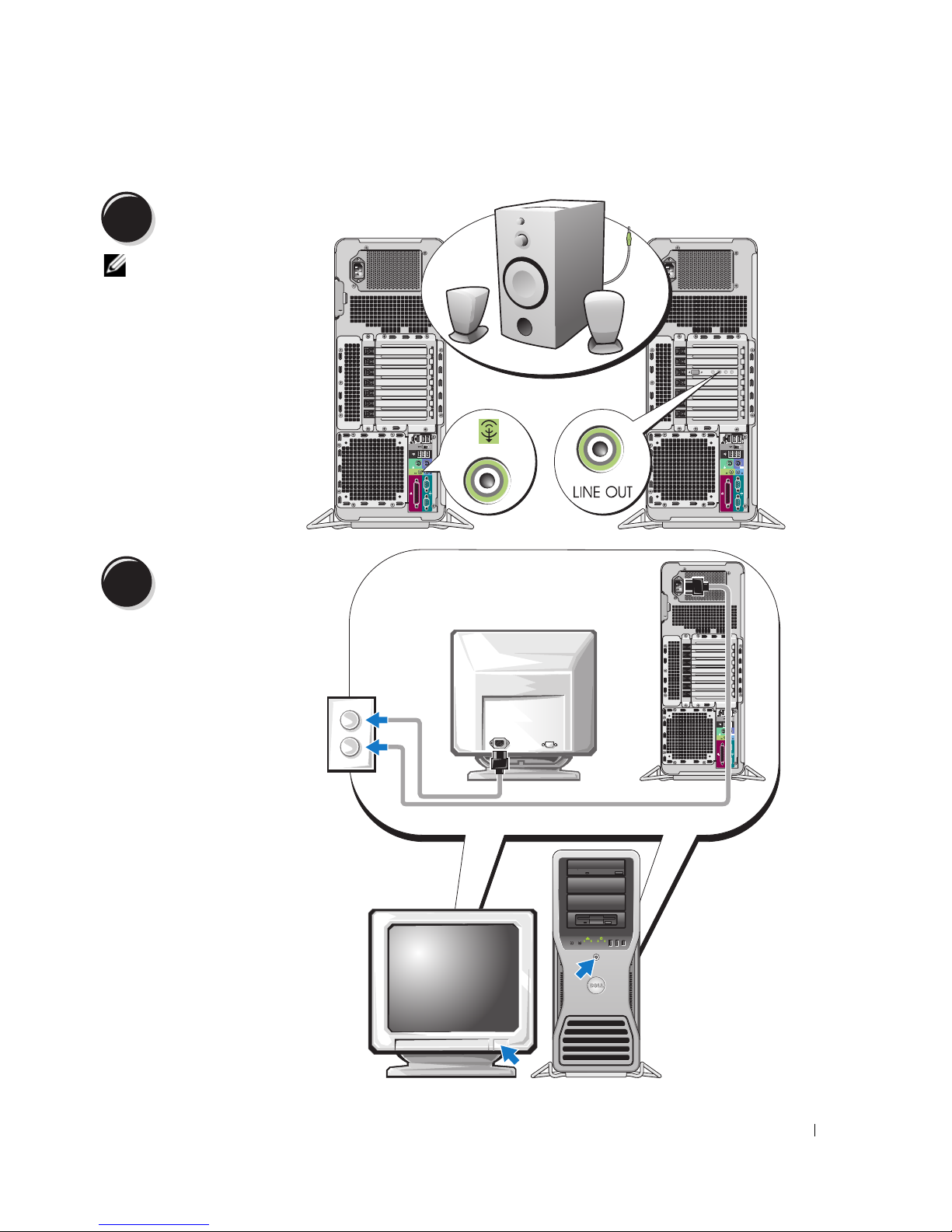
4
5
Connect the speakers.
NOTE: If your
computer has a sound
card installed, connect
the speakers to the
card.
Connect the power
cables and turn on the
computer and monitor.
Quick Reference Guide 13
Page 14

6
Before you install any devices or software that did not come with your computer, read the documentation
that came with the software or device or contact the vendor to verify that the software or device is
compatible with your computer and operating system.
You have now completed the setup for your computer.
Install additional software or devices.
About Your Computer
CAUTION: Your computer is heavy (it has an approximate minimum weight of 55 lbs) and can be difficult to
maneuver. Seek assistance before attempting to lift, move, or tilt it; this computer requires a two-man lift. Always
lift correctly to avoid injury; avoid bending over while lifting. See your Product Information Guide for other
important safety information.
CAUTION: Before setting your computer upright, install the computer stand. Failure to install the stand before
setting the computer upright could cause the computer to tip over, potentially resulting in bodily injury or damage
to the computer.
14 Quick Reference Guide
Page 15

Front View
1
2
13
12
11
10
9
8
3
4
5
6
7
Quick Reference Guide 15
Page 16

1-3 5.25-inch drive bays Can hold a CD/DVD drive, or a Media Card Reader, floppy drive, or SATA hard
drive in a 5.25-inch drive bay carrier.
NOTE: The drive carriers are only for use in the 5.25-inch drive bays. The
floppy-drive/ Media Card Reader and hard-drive carriers are not interchangeable.
4 5.25-inch drive bay with
special 3.5-inch drive
panel plate
Can hold a CD/DVD drive, or a Media Card Reader, floppy drive, or SATA hard
drive in a 5.25-inch drive bay carrier. The drive-panel plate shown here is only for
use with a floppy drive or Media Card Reader; it can be installed in front of any of
the four 5.25-inch drive bays. For more information, see your User’s Guide.
NOTE: The drive carriers are only for use in the 5.25-inch drive bays. The floppy drive/
Media Card Reader and hard drive carriers are not interchangeable.
5 hard-drive activity light The hard drive light is on when the computer reads data from or writes data to the
hard drive. The light might also be on when a device such as your CD player is
operating.
6 IEEE 1394 connector Use the IEEE 1394 connector for high-speed data devices such as digital video
cameras and external storage devices.
16 Quick Reference Guide
Page 17
7 USB 2.0 connectors (2) Use the front USB connectors for devices that you connect occasionally, such as
flash memory keys, cameras, or bootable USB devices (see your User’s Guide for
more information).
It is recommended that you use the back USB connectors for devices that typically
remain connected, such as printers and keyboards.
8 power button Press to turn on the computer.
NOTICE: To avoid losing data, do not use the power button to turn off the
computer. Instead, perform an operating system shutdown.
NOTE: The power button can also be used to wake the system or to place it into a
power-saving state. See your User’s Guide for more information.
9 power light The power light illuminates and blinks or remains solid to indicate different states:
• No light — The computer is turned off or in a hibernation mode.
• Steady green — The computer is in a normal operating state.
• Blinking green — The computer is in a power-saving state.
• Blinking or solid amber — See "Power Problems" in your
To exit from a power-saving state, press the power button or use the keyboard or
the mouse if it is configured as a wake device in the Windows Device Manager. For
more information about sleep states and exiting from a power-saving state, see
your User’s Guide.
See "Diagnostic Lights" on page 35 for a description of light codes that can help
you troubleshoot problems with your computer.
10 microphone connector Use the microphone connector to attach a personal computer microphone for
voice or musical input into a sound or telephony program.
11 headphone connector Use the headphone connector to attach headphones.
12 network link light The network link light is on when a good connection exists between a 10-Mbps,
100-Mbps, or 1000-Mbps (or 1-Gbps) network and the computer.
13 diagnostic lights (4) Use these lights to help you troubleshoot a computer problem based on the
diagnostic code. For more information, see "Diagnostic Lights" on page 35.
User’s Guide
.
Quick Reference Guide 17
Page 18
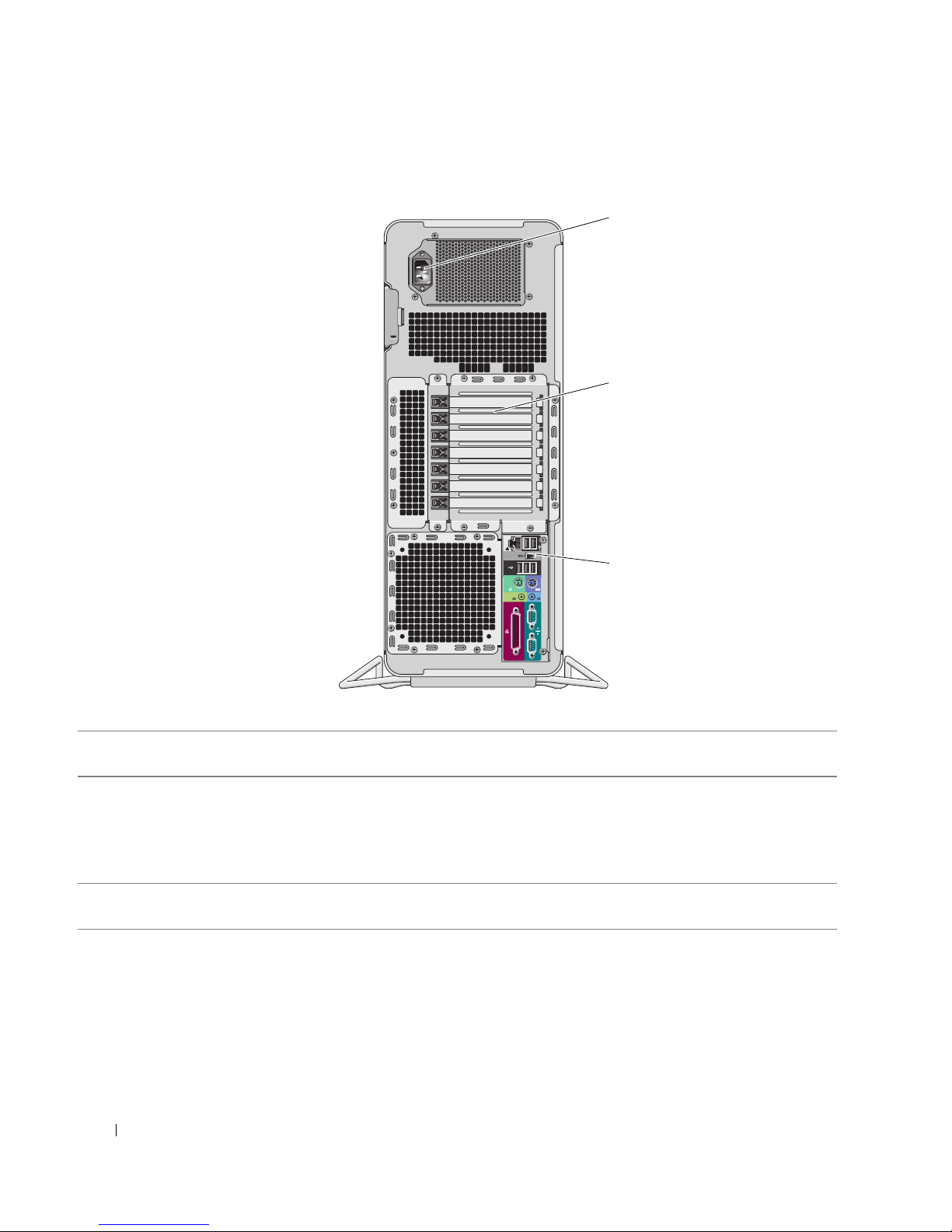
Back View
1
2
3
1 power connector Insert the power cable. The appearance of this connector may differ from what is
2 card slots Access connectors for any installed PCI, PCI-X, or PCI Express cards.
pictured here.
NOTE: The center five connector slots support full-length cards: one PCI, one PCI
express x16, one PCI express x8 (wired as x4), and two PCI-X slots; the connector
slots at the top and at the bottom support half-length cards: two PCI express x8 slots
(wired as x4).
3 back panel connectors Plug serial, USB, and other devices into the
Connectors" on page 19).
appropriate connector
(see "Back Panel
18 Quick Reference Guide
Page 19
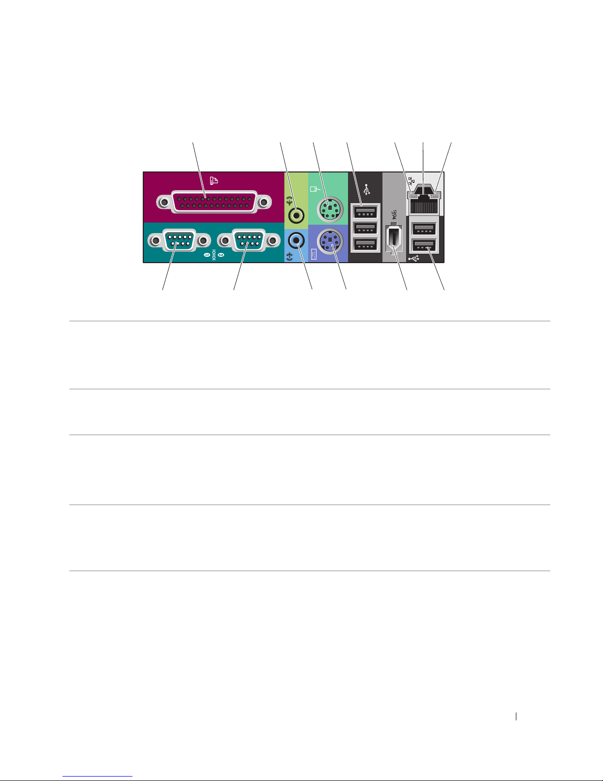
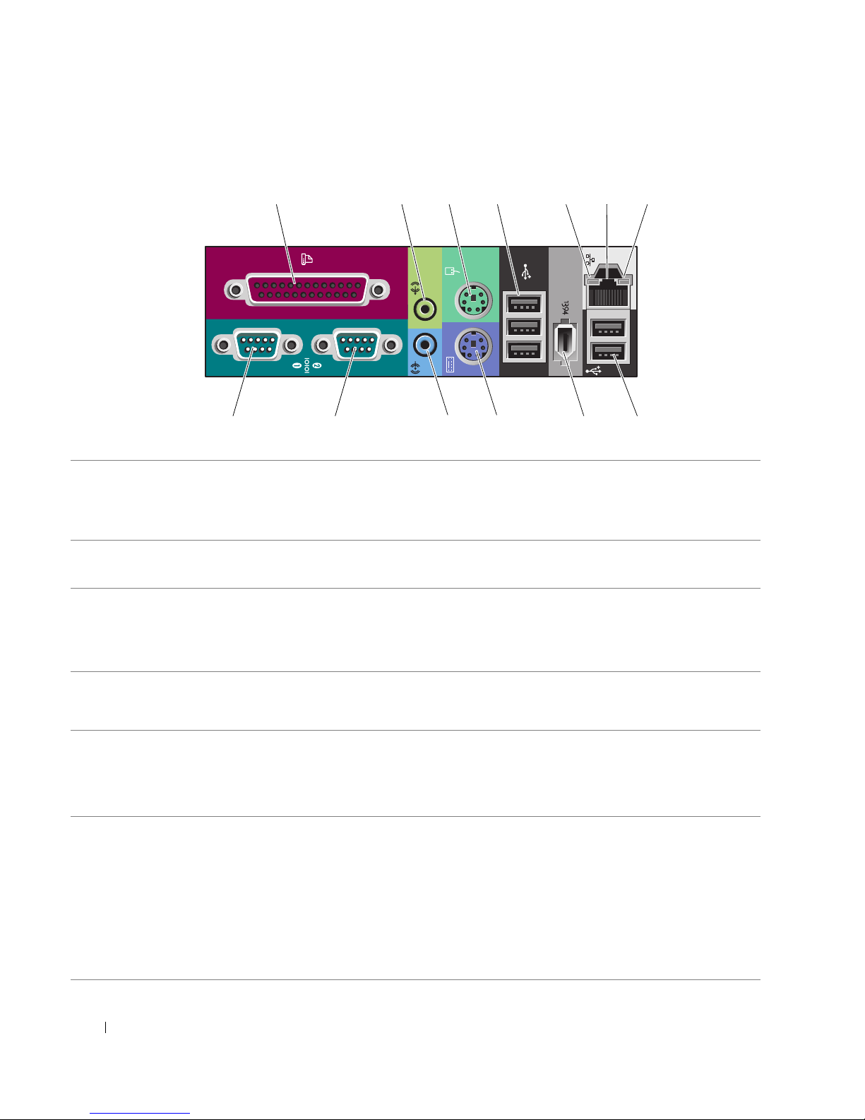
Back Panel Connectors
1 234 6
57
13 12 11 10 89
1 parallel connector Connect a parallel device, such as a printer, to the parallel connector. If you have a
USB printer, plug it into a USB connector.
NOTE: The integrated parallel connector is automatically disabled if the computer
detects an installed card containing a parallel connector configured to the same
address. For more information, see your User’s Guide.
2 line-out/ headphone
connector
3 mouse connector Plug a standard mouse into the green mouse connector. Turn off the computer
4 USB 2.0 connectors (3) It is recommended that you use the front USB connectors for devices that you
Use the green line-out connector to attach headphones and most speakers with
integrated amplifiers.
On computers with a sound card, use the connector on the card.
and any attached devices before you connect a mouse to the computer. If you have
a USB mouse, plug it into a USB connector.
®
If your computer is running the Microsoft
Windows® XP operating system, the
necessary mouse drivers have been installed on your hard drive.
connect occasionally, such as flash memory keys, cameras, or bootable USB
devices.
Use the back USB connectors for devices that typically remain connected, such as
printers and keyboards.
Quick Reference Guide 19
Page 20

5 link integrity light
6 network adapter
connector
• Green — A good connection exists between a 10-Mbps network and the
computer.
• Orange — A good connection exists between a 100-Mbps network and the
computer.
• Yellow — A good connection exists between a 1000-Mbps (or 1-Gbps) network
and the computer.
• Off — The computer is not detecting a physical connection to the network.
To attach your computer to a network or broadband device, connect one end of a
network cable to either a network jack or your network or broadband device.
Connect the other end of the network cable to the network adapter connector on
your computer. A click indicates that the network cable has been securely
attached.
NOTE: Do not plug a telephone cable into the network connector.
On computers with an additional network connector card, use the connectors on
the card and on the back of the computer when setting up multiple network
connections (such as a separate intra- and extranet).
It is recommended that you use Category 5 wiring and connectors for your
network. If you must use Category 3 wiring, force the network speed to 10 Mbps to
ensure reliable operation.
7 network activity light Flashes a yellow light when the computer is transmitting or receiving network
data. A high volume of network traffic may make this light appear to be in a steady
"on" state.
8 USB 2.0 connectors (2) It is recommended that you use the front USB connectors for devices that you
connect occasionally, such as flash memory keys, cameras, or bootable USB
devices.
Use the back USB connectors for devices that typically remain connected, such as
printers and keyboards.
9 IEEE 1394 connector Use the IEEE 1394 connector for high-speed data devices such as digital video
cameras and external storage devices.
10 keyboard connector If you have a standard keyboard, plug it into the purple keyboard connector. If you
have a USB keyboard, plug it into a USB connector.
11 line-in connector Use the blue line-in connector to attach a record/playback device such as a cassette
player, CD player, or VCR.
On computers with a sound card, use the connector on the card.
12 serial connector Connect a serial device, such as a handheld device, to the serial port. If necessary,
the address for this port can be modified through System Setup (see your User’s
Guide for more information).
13 serial connector Connect a serial device, such as a handheld device, to the serial port. If necessary,
the address for this port can be modified through System Setup (see your User’s
Guide for more information).
20 Quick Reference Guide
Page 21
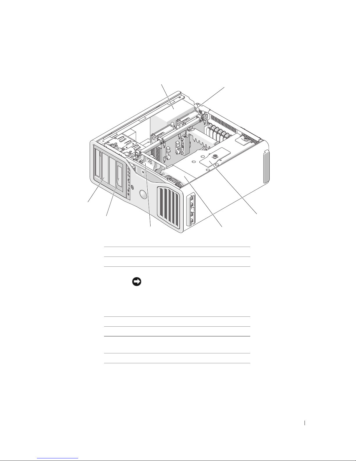
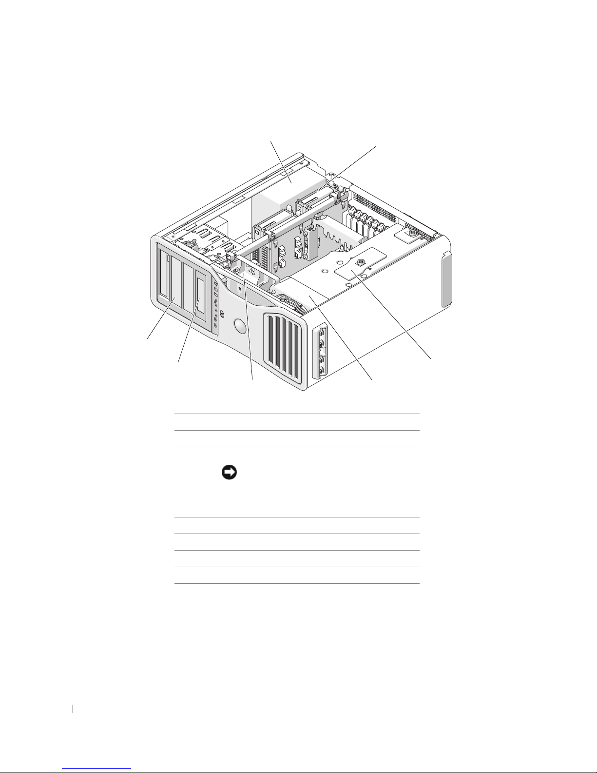
Inside View
1
2
7
6
45
1 power supply
2 hard drive bay
3 memory shroud
NOTICE: The memory shroud holds the
(optional) memory riser cards in place; its
4 front fan
5 card fan
6 5.25-inch drive bay with 3.5-inch drive panel
7 5.25-inch drive bay
thumbscrews must be sufficiently tight in
order to secure the risers and to avoid
damage.
plate
3
Quick Reference Guide 21
Page 22
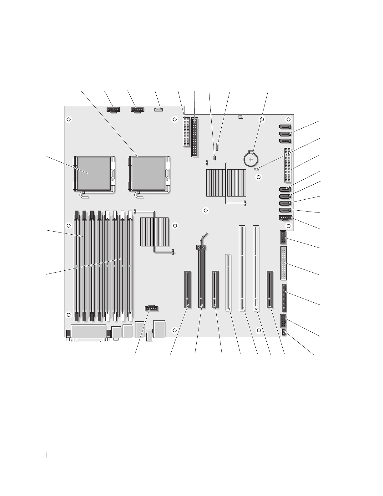
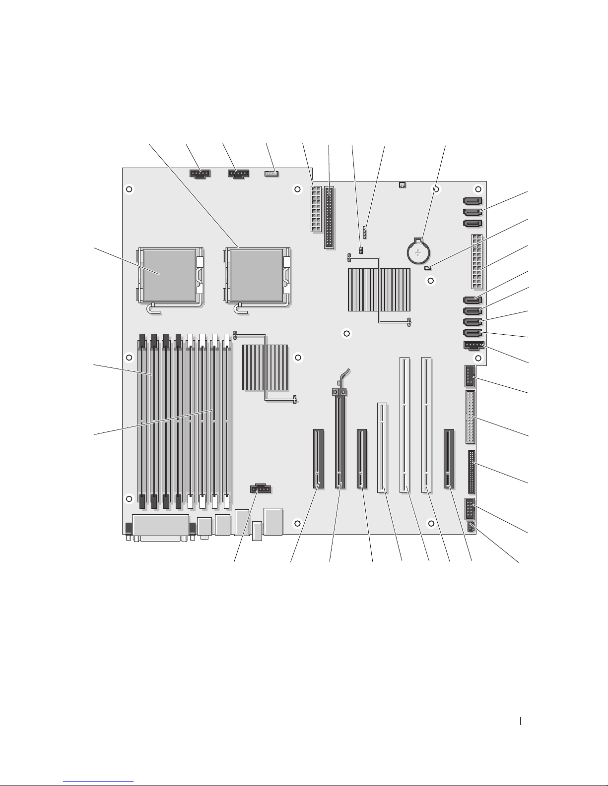
System Board Components
2 3456 9
1 8
7
10
11
33
32
31
12
13
14
15
16
17
18
19
20
22 Quick Reference Guide
30
21
26272829
232425
22
Page 23

1 secondary processor connector (CPU_1) 18 FlexBay connector (USB)
2 front fan connector (FAN_FRONT) 19 floppy drive (DSKT)
3 card cage fan connector (FAN_CCAG) 20 front panel connector (FRONTPANEL)
4 internal speaker connector (INT_SPKR) 21 front panel 1394 connector (FP1394)
5 power connector (POWER2) 22 chassis intrusion header (INTRUDER)
6 IDE drive connector (IDE) 23 PCI-Express x8 card slot, wired as x4
(SLOT7_PCIE)
7 password jumper (PSWD) 24 PCI-X card slot (SLOT6_PCIX)
8 auxiliary hard-drive LED connector
(AUX_LED)
9 battery socket (BATTERY) 26 PCI card slot (SLOT4_PCI)
25 PCI-X card slot (SLOT5_PCIX)
NOTE: This slot is not available in the dual-
graphics configuration
10 SATA connectors (SATA_0, SATA_1, SATA_2) 27 PCI-Express x8 card slot, wired as x4
(SLOT3_PCIE)
NOTE: In the dual-graphics configuration, this slot
is replaced by a x16 slot on the graphics riser. It
holds a graphic card.
11 RTC reset jumper (RTCRST) 28 PCI-Express x16 card slot (SLOT2_PCIE)
NOTE: This slot is not available in the dual-
graphics configuration
12 main power connector (POWER1) 29 PCI-Express x8 card slot, wired as x4
(SLOT1_PCIE)
NOTE: In the dual-graphics configuration, this slot
is replaced by a x16 slot on the graphics riser. It
holds a graphics card.
13 hard drive connector (HDD_3) 30 memory fan connector (FAN_MEM)
14 hard drive connector (HDD_2) 31 white memory module connectors (DIMM_1-4)
support memory modules or memory module
risers
15 hard drive connector (HDD_1) 32 black memory module connectors (DIMM_5-8)
support memory modules only when no memory
riser cards are installed; otherwise these must be
left empty
16 hard drive connector (HDD_0) 33 primary processor connector (CPU_0)
17 hard drive fan (FAN_HDD)
Quick Reference Guide 23
Page 24
Cable Colors
Device Color
Hard drive (with on-board
controller)
Floppy drive black pull-tab
CD/DVD drive orange pull-tab
blue cable
Locating Your User’s Guide
Your
User’s Guide
• Technical specifications
• Front and back views of your computer, including all of the available connectors
• Inside views of your computer, including a detailed graphic of the system board and the connectors
• Instructions for cleaning your computer
• Information on software features, such as Legacy Select Technology control, using a password, and
system setup options
• Tips and information for using the Microsoft Windows XP operating system
• Instructions for removing and installing parts, including memory, cards, drives, the microprocessor, and
the battery
contains additional information about your computer such as:
• Information for troubleshooting various computer problems
• Instructions for using the Dell Diagnostics and reinstalling drivers
• Information on how to contact Dell
You can access the
User’s Guide
from your hard drive or the Dell Support website at
support.dell.com
Removing the Computer Cover
CAUTION: Before you begin any of the procedures in this section, follow the safety instructions in the Product
Information Guide.
CAUTION: To guard against electrical shock, always unplug your computer from the electrical outlet before
removing the cover.
CAUTION: Your computer is heavy (it has an approximate minimum weight of 55 lbs) and can be difficult to
maneuver. Seek assistance before attempting to lift, move, or tilt it; this computer requires a two-man lift. Always
lift correctly to avoid injury; avoid bending over while lifting. See your Product Information Guide for other
important safety information.
CAUTION: The computer stand should be installed at all times to ensure maximum system stability. Failure to
install the stand could result in the computer tipping over, potentially resulting in bodily injury or damage to the
computer.
.
24 Quick Reference Guide
Page 25

NOTICE: To prevent static damage to components inside your computer, discharge static electricity from your
body before you touch any of your computer’s electronic components. You can do so by touching an unpainted
metal surface on the computer.
1
Follow the procedures in "Before You Begin" in the
NOTICE: Opening the computer cover while the computer is running could result in a shutdown without warning
and a loss of data in open programs. The computer cooling system cannot function properly while the cover is
removed.
2
If you have installed a security cable, remove it from the security cable slot.
3
Carefully, with the help of an assistant, remove the computer stand (see "Removing the Computer
User’s Guide
.
Stand").
CAUTION: Your computer is heavy (it has an approximate minimum weight of 55 lbs) and can be difficult to
maneuver. Seek assistance before attempting to lift, move, or tilt it; this computer requires a two-man lift. Always
lift correctly to avoid injury; avoid bending over while lifting. See your Product Information Guide for other
important safety information.
CAUTION: The computer stand should be installed at all times to ensure maximum system stability. Failure to
install the stand could result in the computer tipping over, potentially resulting in bodily injury or damage to the
computer.
NOTICE: Ensure that you are working on a level, protected surface to avoid scratching either the computer or the
surface on which it is resting.
4
Carefully, with the help of an assistant, lower your computer down to a flat surface with the cover
facing up.
5
Pull back the cover latch release.
NOTICE: Ensure that sufficient space exists to support the removed cover—at least 30 cm (1 ft) of desk top space.
Quick Reference Guide 25
Page 26
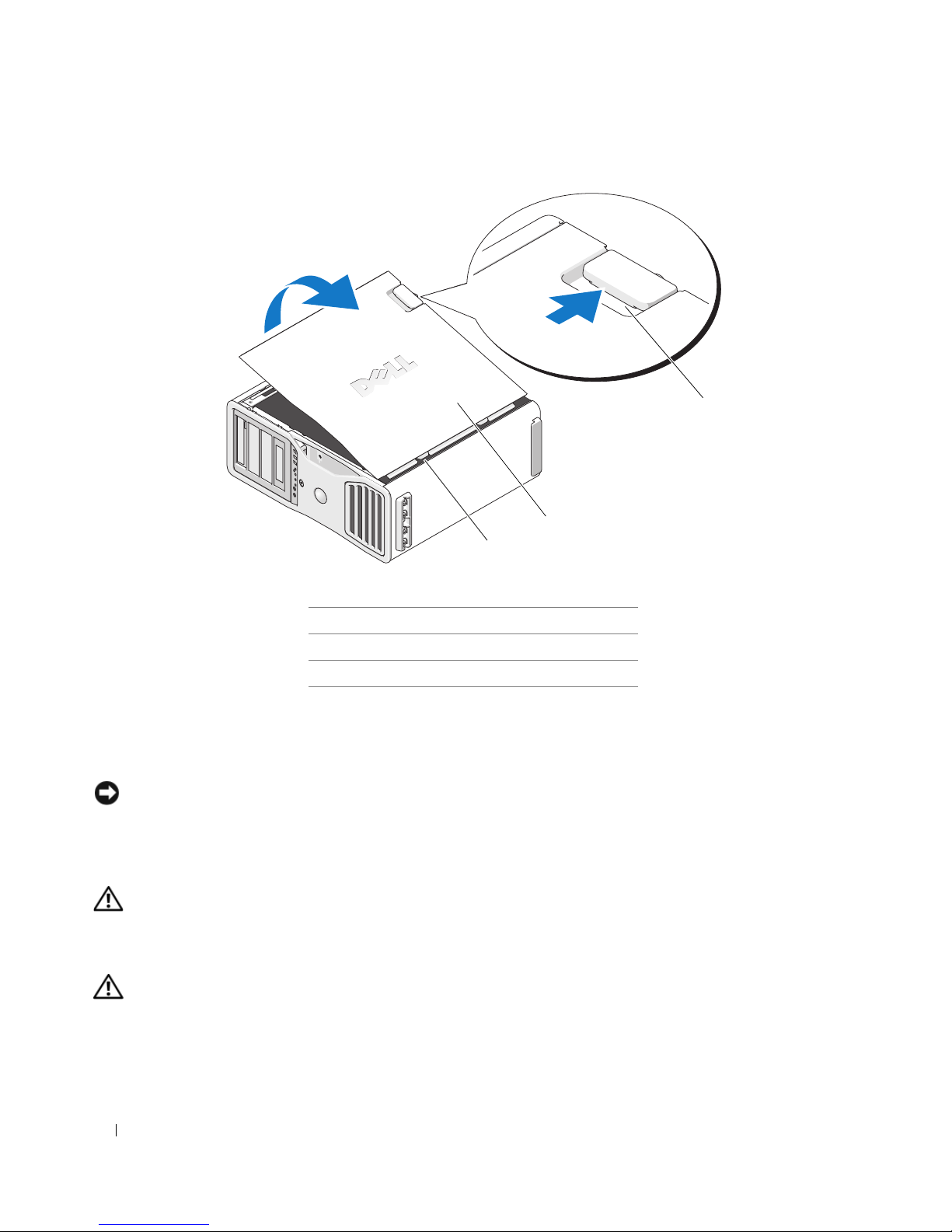
1
2
3
1 cover latch release
2 computer cover
3 cover hinges
6
Locate the three hinge tabs on the edge of the computer.
7
Grip the sides of the computer cover and pivot the cover up, using the hinges as leverage points.
8
Release the cover from the hinge tabs and set it aside in a secure location.
NOTICE: The computer cooling system cannot function properly while the computer cover is not installed. Do not
attempt to boot the computer before reinstalling the computer cover.
Computer Stand
CAUTION: Your computer is heavy (it has an approximate minimum weight of 55 lbs) and can be difficult to
maneuver. Seek assistance before attempting to lift, move, or tilt it; this computer requires a two-man lift. Always
lift correctly to avoid injury; avoid bending over while lifting. See your Product Information Guide for other
important safety information.
CAUTION: The computer stand should be installed at all times to ensure maximum system stability. Failure to
install the stand could result in the computer tipping over, potentially resulting in bodily injury or damage to the
computer.
26 Quick Reference Guide
Page 27
CAUTION: Before you begin any of the procedures in this section, follow the safety instructions in the Product
Information Guide.
CAUTION: To guard against electrical shock, always unplug your computer from the electrical outlet before
removing the cover.
NOTICE: To prevent static damage to components inside your computer, discharge static electricity from your
body before you touch any of your computer’s electronic components. You can do so by touching an unpainted
metal surface on the computer.
Attaching the Computer Stand
CAUTION: Your computer is heavy (it has an approximate minimum weight of 55 lbs) and can be difficult to
maneuver. Seek assistance before attempting to lift, move, or tilt it; this computer requires a two-man lift. Always
lift correctly to avoid injury; avoid bending over while lifting. See your Product Information Guide for other
important safety information.
CAUTION: The computer stand should be installed at all times to ensure maximum system stability. Failure to
install the stand could result in the computer tipping over, potentially resulting in bodily injury or damage to the
computer.
1
Follow the procedures in "Before You Begin" in the
2
If you have installed a security cable, remove it from the security cable slot.
3
Set the stand on the ground in front of the computer, so that the front and the back of the stand touch
the ground.
If the front and the back of the stand point up toward the ceiling, the stand is upside down.
User’s Guide
.
4
Ensure that the alignment guide faces the computer.
If the alignment guide points away from the computer, the stand is backwards.
Quick Reference Guide 27
Page 28
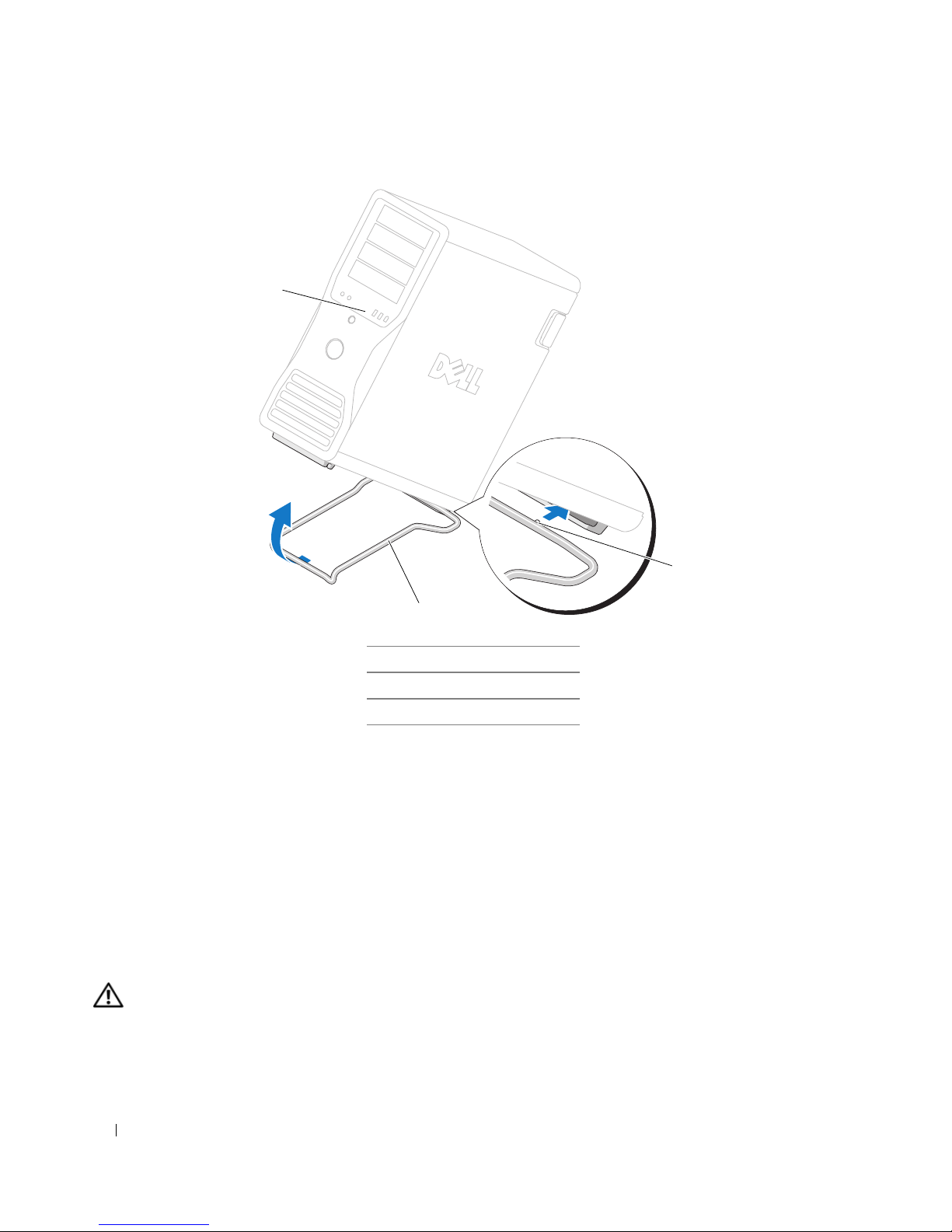
1
3
2
1 computer
2 computer stand
3 alignment guide
5
Align the center of the stand with the center of the computer.
6
Carefully, with the help of an assistant, tilt the computer backwards slightly- just high enough to slide
the stand beneath it.
7
Slide the rear of the stand into the rear foot of the computer, and ensure that the alignment guide
slides into place.
8
Center the front bar of the stand in the corresponding notch in the front foot of the computer.
9
Carefully set the computer back down; the front bar of the stand should snap into place under the
weight of the computer.
Removing the Computer Stand
CAUTION: Your computer is heavy (it has an approximate minimum weight of 55 lbs) and can be difficult to
maneuver. Seek assistance before attempting to lift, move, or tilt it; this computer requires a two-man lift. Always
lift correctly to avoid injury; avoid bending over while lifting. See your Product Information Guide for other
important safety information.
28 Quick Reference Guide
Page 29

CAUTION: The computer stand should be installed at all times to ensure maximum system stability. Failure to
install the stand could result in the computer tipping over, potentially resulting in bodily injury or damage to the
computer.
1
Follow the procedures in "Before You Begin" in the
2
Carefully, with the help of an assistant, tip the computer back at a very slight angle from the ground.
3
Pull the front of the computer stand down towards the ground, to release it from the front of the
computer.
4
Pull the computer stand toward the front of the computer until the stand is free.
User’s Guide
.
Caring for Your Computer
To help maintain your computer, follow these suggestions:
• To avoid losing or corrupting data, never turn off your computer when the hard drive light is on.
• Schedule regular virus scans using virus software.
• Manage hard drive space by periodically deleting unnecessary files and defragmenting the drive.
• Back up files on a regular basis.
• Periodically clean your monitor screen, mouse, and keyboard (see your
information).
User’s Guide
for more
Solving Problems
Troubleshooting Tips
Perform the following checks when you troubleshoot your computer:
• If you added or removed a part before the problem started, review the installation procedures and
ensure that the part is correctly installed.
• If a peripheral device does not work, ensure that the device is properly connected.
• If an error message appears on the screen, write down the exact message. The message may help
technical support personnel diagnose and fix the problem(s).
• If an error message occurs in a program, see the program’s documentation.
• If the recommended action in the troubleshooting section is to see a section in your
support.dell.com (on another computer if necessary) to access your
User’s Guide.
User’s Guide
Resolving Software and Hardware Incompatibilities
If a device is either not detected during the operating system setup or is detected but incorrectly configured,
you can use the Hardware Troubleshooter to resolve the incompatibility.
, go to
Quick Reference Guide 29
Page 30

To resolve incompatibilities using the Hardware Troubleshooter:
1
Click the
2
Ty p e
3
Click
4
In the
click
Start
button and click
hardware troubleshooter
Hardware Troubleshooter
Hardware Troubleshooter
Next
.
Help and Support
in the
list, click
in the
Search
Search Results
I need to resolve a hardware conflict on my computer
.
field and click the arrow to start the search.
list.
, and
Using Microsoft® Windows® XP System Restore
The Microsoft Windows XP operating system provides System Restore to allow you to return your computer
to an earlier operating state (without affecting data files) if changes to the hardware, software, or other
system settings have left the computer in an undesirable operating state. See the Windows Help and
Support Center (see "Finding Information" on page 5) for information about using System Restore.
NOTICE: Make regular backups of your data files. System Restore does not monitor your data files or recover
them.
Creating a Restore Point
1
Click the
2
Click
3
Follow the instructions on the screen.
Start
button and click
System Restore
Help and Support
.
.
Restoring the Computer to an Earlier Operating State
NOTICE: Before you restore the computer to an earlier operating state, save and close any open files and exit any
open programs. Do not alter, open, or delete any files or programs until the system restoration is complete.
1
Click the
Restore
2
Ensure that
3
Click a calendar date to which you want to restore your computer.
The
Start
button, point to
.
Restore my computer to an earlier time
Select a Restore Point
All Programs→
Accessories→
System Tools
is selected and click
, and then click
Next
.
System
screen provides a calendar that allows you to see and select restore points.
All calendar dates with available restore points appear in boldface type.
4
Select a restore point and click
Next
.
If a calendar date has only one restore point, then that restore point is automatically selected. If two or
more restore points are available, click the restore point that you prefer.
5
Click
Next
.
Restoration Complete
The
screen appears after System Restore finishes collecting data and then the
computer restarts.
6
After the computer restarts, click OK.
30 Quick Reference Guide
Page 31

To change the restore point, you can either repeat the steps using a different restore point, or you can undo
the restoration.
Undoing the Last System Restore
NOTICE: Before you undo the last system restore, save and close all open files and exit any open programs. Do not
alter, open, or delete any files or programs until the system restoration is complete.
1
Click the
Restore
2
Click
3
Click
The
4
After the computer restarts, click OK.
Enabling System Restore
Start
button, point to
.
Undo my last restoration
Next
.
System Restore
screen appears and the computer restarts.
All Programs→ Accessories→ System Tools
and click
Next
.
, and then click
System
If you reinstall Windows XP with less than 200 MB of free hard-disk space available, System Restore is
automatically disabled. To see if System Restore is enabled:
1
Click the
2
Click
Start
button and click
Control Panel
Performance and Maintenance
.
.
3
Click
4
Click the
5
Ensure that
System
.
System Restore
tab.
Turn off System Restore
is unchecked.
Using the Last Known Good Configuration
1
Restart your computer and press <F8> when the message
system to start
2
Highlight
Last Known Good Configuration
appears.
, press <Enter>, press <l>, and then select your
operating system when prompted.
Other Options to Help Resolve Additional Device or Software Conflicts
NOTICE: The following processes erase all of the information on your hard drive.
• Reinstall your operating system using the operating system installation guide and
System
CD.
During the operating system reinstallation, you can select to delete the existing partitions and reformat
your hard drive.
• Reinstall all drivers, beginning with the chipset, using the
Please select the operating
Operating
Drivers and Utilities
CD
.
Quick Reference Guide 31
Page 32

Dell Diagnostics
CAUTION: Before you begin any of the procedures in this section, follow the safety instructions in the Product
Information Guide.
When to Use the Dell Diagnostics
If you experience a problem with your computer, perform the checks in "Solving Problems" on page 29 and
run the Dell Diagnostics before you contact Dell for technical assistance.
It is recommended that you print these procedures before you begin.
NOTICE: The Dell Diagnostics works only on Dell computers. Using this program with other computers can cause
incorrect computer responses or result in error messages.
The Dell Diagnostics allow you to:
• Perform quick checks or extensive tests on one or all devices
• Choose how many times a test is run
• Display or print test results or save them in a file
• Suspend testing if an error is detected or terminate testing if a certain number of errors occur
Help
• Access online
• Read status messages that tell you whether tests completed successfully
• Receive error messages if problems are detected
screens that describe the tests and how to run them
Starting the Dell Diagnostics From Your Hard Drive
1
Turn on (or restart) your computer.
2
When the DELL™ logo appears, press <F12> immediately.
NOTE: If you see a message stating that no diagnostics utility partition has been found, see "Starting the Dell
Diagnostics From the Drivers and Utilities CD" on page 33.
If you wait too long and the operating system logo appears, continue to wait until you see the
Microsoft Windows desktop. Then shut down your computer and try again. For more information on
shutting down your computer, see your
3
When the boot device list appears, highlight
4
When the Dell Diagnostics
on the tests, see your
Main Menu
User’s Guide.
User’s Guide.
Boot to Utility Partition
and press <Enter>.
appears, select the test you want to run. For more information
32 Quick Reference Guide
Page 33
Starting the Dell Diagnostics From the Drivers and Utilities CD
NOTE: The Drivers and Utilities CD is optional and may not ship with all computers.
1
Insert the
2
Shut down your computer.
Drivers and Utilities
CD.
When the DELL logo appears, press <F12> immediately.
If you wait too long and the Windows logo appears, continue to wait until you see the Windows
desktop. Then shut down your computer, and try again.
NOTE: The next steps change the boot sequence for one time only. On the next start-up, the computer boots
according to the devices specified in system setup.
3
When the boot device list appears, highlight
4
Select the
5
Select the
6
Ty p e 1 to start the ResourceCD menu.
7
Select the option to start the Dell Diagnostics and press <Enter>.
8
Select
Onboard or USB CD-ROM Drive
Boot from CD-ROM
option from the menu that appears.
Run the 32 Bit Dell Diagnostics
Onboard or USB CD-ROM Drive
and press <Enter>.
option from the CD boot menu.
from the numbered list. If multiple versions are listed, select
the version appropriate for your computer.
9
When the Dell Diagnostics
Main Menu
appears, select the test that you want to run.
Before you start testing
CAUTION: Before you begin any of the procedures in this section, follow the safety instructions in the Product
Information Guide.
• Turn on your printer if one is attached.
• Enter system setup, review your computer’s configuration information, and enable all of your
computer’s components and devices, such as connectors.
Beep Codes
Your computer might emit a series of beeps during start-up if the monitor cannot display errors or problems.
This series of beeps, called a beep code, identifies a problem. One possible beep code (code 1-3-1) consists
of one beep, a burst of three beeps, and then one beep. This beep code tells you that the computer
encountered a memory problem.
If your computer beeps during start-up:
1
Write down the beep code on the "Diagnostics Checklist" in your
2
Run the Dell Diagnostics to identify a more serious cause.
3
Contact Dell for technical assistance.
User’s Guide
.
Quick Reference Guide 33
Page 34

Code Cause
1-1-2 Microprocessor register failure
1-1-3 NVRAM read/write failure
1-1-4 ROM BIOS checksum failure
1-2-1 Programmable interval timer failure
1-2-2 DMA initialization failure
1-2-3 DMA page register read/write failure
1-3 Video Memory Test failure
1-3-1 through 2-4-4 Memory not being properly identified or used
1-3-2 Memory problem
3-1-1 Slave DMA register failure
3-1-2 Master DMA register failure
3-1-3 Master interrupt mask register failure
3-1-4 Slave interrupt mask register failure
3-2-2 Interrupt vector loading failure
3-2-4 Keyboard Controller Test failure
3-3-1 NVRAM power loss
3-3-2 Invalid NVRAM configuration
3-3-4 Video Memory Test failure
3-4-1 Screen initialization failure
3-4-2 Screen retrace failure
3-4-3 Search for video ROM failure
4-2-1 No timer tick
4-2-2 Shutdown failure
4-2-3 Gate A20 failure
4-2-4 Unexpected interrupt in protected mode
4-3-1 Memory failure above address 0FFFFh
4-3-3 Timer-chip counter 2 failure
4-3-4 Time-of-day clock stopped
4-4-1 Serial or parallel port test failure
4-4-2 Failure to decompress code to shadowed memory
34 Quick Reference Guide
Page 35
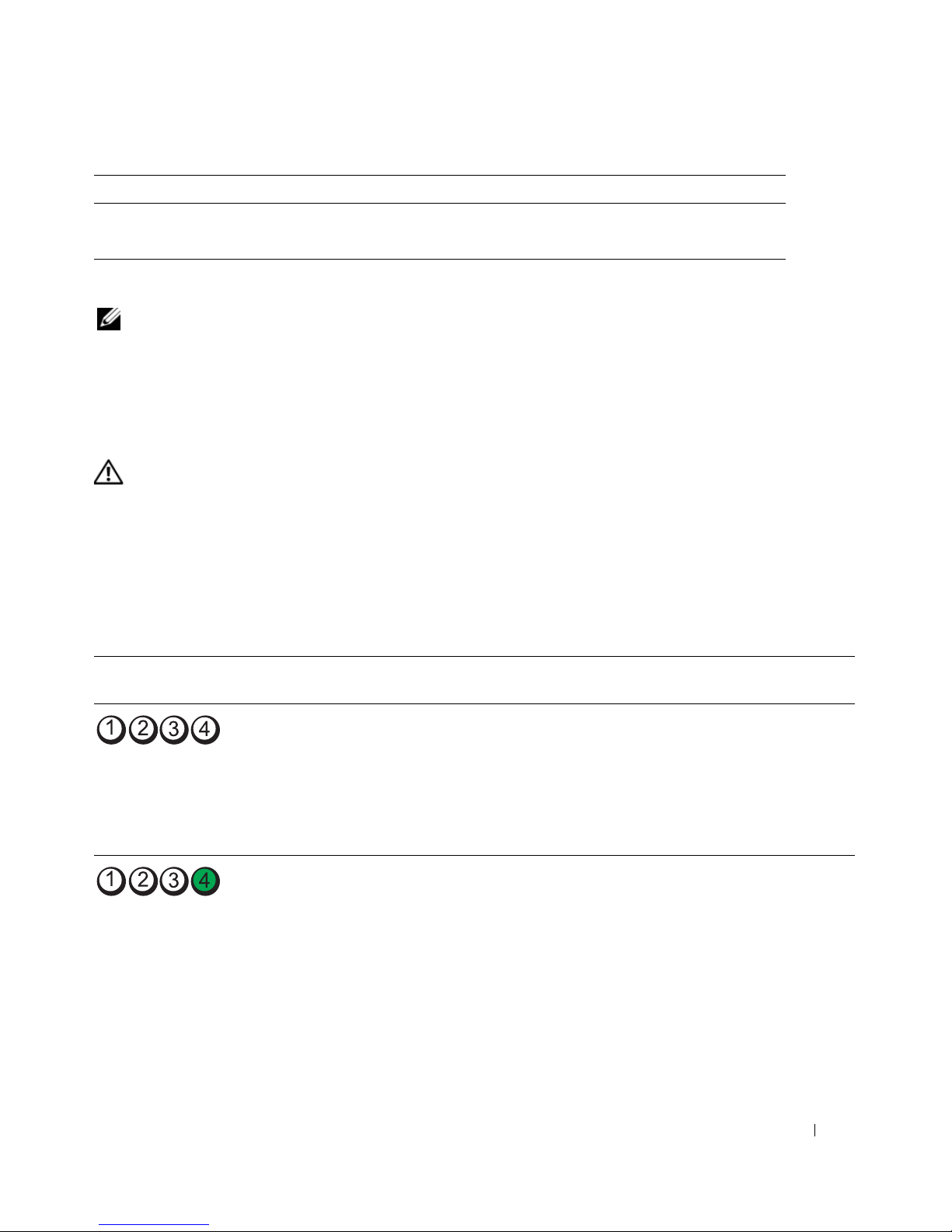
Code Cause
4-4-3 Math-coprocessor test failure
4-4-4 Cache test failure
Error Messages
NOTE: If the message is not listed, see the documentation for either the operating system or the program that was
running when the message appeared.
If an error occurs during start-up, a message may be displayed on the monitor identifying the problem. See
"Error Messages" in the
User’s Guide
for suggestions on resolving any problems.
Diagnostic Lights
CAUTION: Before you begin any of the procedures in this section, follow the safety instructions in the Product
Information Guide.
To help you troubleshoot a problem, your computer has four lights labeled "1," "2," "3," and "4" on the front.
The lights can be "off" or green. When the computer starts normally, the lights flash. If the computer
malfunctions, the pattern of the lights and also that of the power button help to identify the problem. These
lights also indicate sleep states.
Diagnostic Light Codes Before POST
Diagnostic Lights Power
Light
off No electrical power is
off The computer is in a normal
Problem Description Suggested Resolution
Connect the computer to an electrical outlet.
supplied to the computer.
off condition; the computer is
connected to an electrical
outlet.
Ensure that the front-panel power light is on. If
the power light is off, ensure that the computer
is connected to a working electrical outlet and
then press the power button.
If the problem is still not resolved, contact Dell
for technical assistance.
Press the power button to turn the computer
on.
If the computer does not turn on, ensure that
the front-panel power light is on. If the power
light is off, ensure that the computer is
connected to a working electrical outlet and
then press the power button.
If the problem is still not resolved, contact Dell
for technical assistance.
Quick Reference Guide 35
Page 36
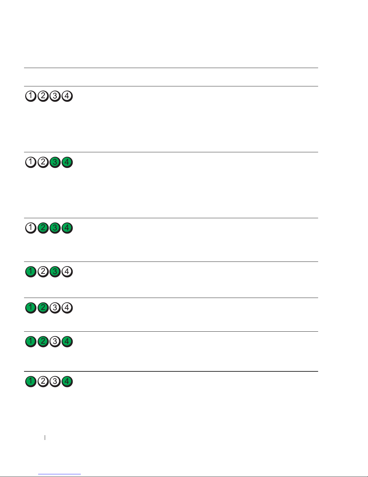
Diagnostic Lights Power
Light
Problem Description Suggested Resolution
(blinking)
blinking
green
The computer is in a reduced
power or "sleep" state.
Use one of the appropriate methods to "wake
up" the computer. See "Advanced Features" in
your User’s Guide.
If the problem is not resolved and you are trying
to wake the computer with a USB mouse or
keyboard, substitute the mouse or keyboard
with a working PS/2 mouse or keyboard and
then try to wake the computer.
blinking
green
The computer is in a reduced
power or "sleep" state.
Use one of the appropriate methods to "wake
up" the computer. See "Advanced Features" in
your User’s Guide.
If the problem is not resolved and you are trying
to wake the computer with a USB mouse or
keyboard, substitute the mouse or keyboard
with a working PS/2 mouse or keyboard and
then try to wake the computer.
amber The BIOS is not executing. Ensure that the processor is seated correctly and
restart the computer. See "Processor" in your
User’s Guide.
If the problem is still not resolved, contact Dell
for technical assistance.
blinking
amber
(blinking)
amber A possible system board
(blinking)
amber A processor mismatch exists. Perform the procedure in "Processor Problems"
(blinking)
amber A possible failure has been
(blinking)
36 Quick Reference Guide
A possible power supply or
power cable failure has
occurred.
failure has occurred.
detected in a plug-in
component such as a graphics
riser card or memory riser
card.
Perform the procedure in "Power Problems" in
your User’s Guide.
If the problem is still not resolved, contact Dell
for technical assistance.
Contact Dell for technical assistance.
in your User’s Guide.
Verify that any required power cables are
connected to the memory and graphics riser
cards.
Perform the procedure in "Power Problems" in
your User’s Guide.
Page 37
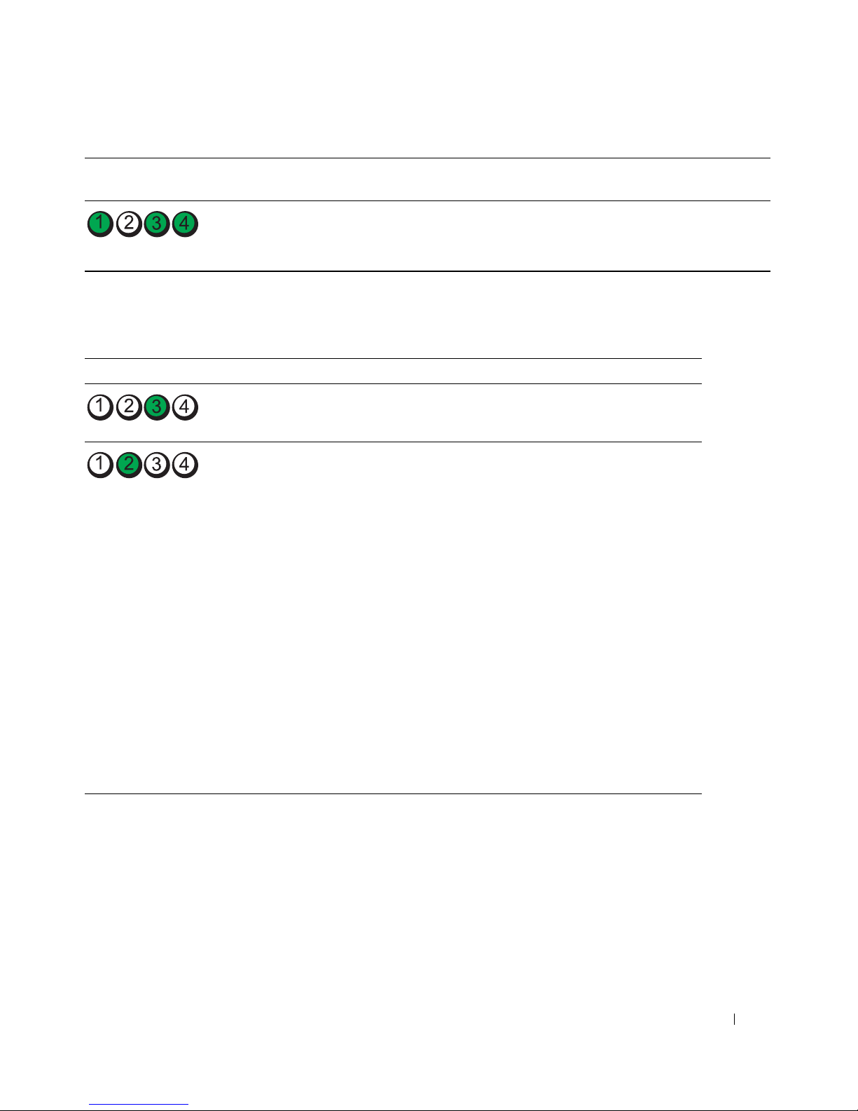
Diagnostic Lights Power
Light
Problem Description Suggested Resolution
amber A possible power supply
failure has occurred.
Verify that both power supply cables are
plugged in to the motherboard.
(blinking)
Diagnostic Light Codes During POST
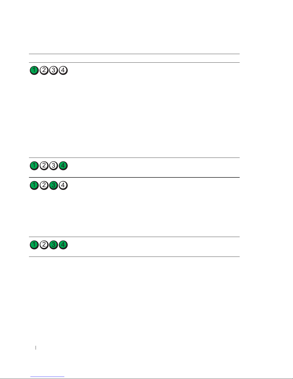
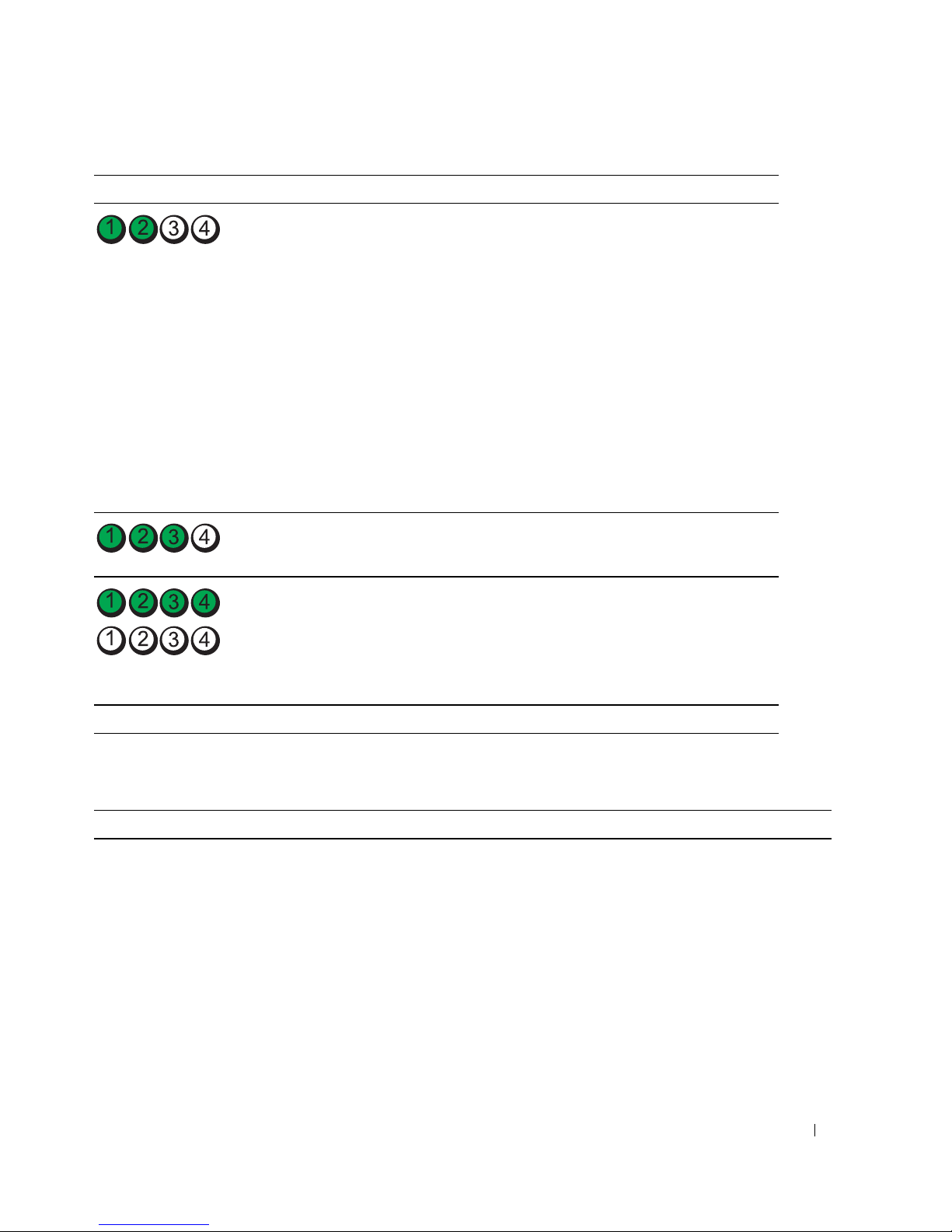
The power light displays a solid green for diagnostic light codes during POST.
Light Pattern Problem Description Suggested Resolution
A possible processor failure has occurred. Reinstall the processor and restart the
computer.
A possible expansion card failure has
occurred.
1
Determine if a conflict exists by
removing a card (not the graphics
card) and then restarting the
computer.
2
If the problem persists, reinstall the
card that you removed, remove a
different card, and then restart the
computer.
3
Repeat this process for each card. If
the computer starts normally,
troubleshoot the last card removed
from the computer for resource
conflicts (see "Resolving Software and
Hardware Incompatibilities" on
page 29).
4
Move each card one at a time to a
different PCI slot and restart the
computer after each move.
5
If the problem persists, contact Dell
.
Quick Reference Guide 37
Page 38
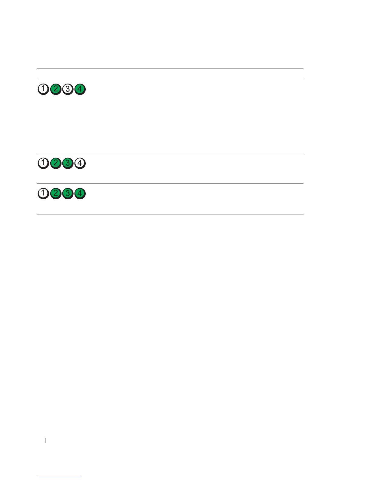
Light Pattern Problem Description Suggested Resolution
A possible graphics card failure has
occurred.
1
If the computer has a graphics card,
remove the card, reinstall it, and then
restart the computer.
2
If the problem still exists, install a
graphics card that you know works and
restart the computer.
3
If the problem persists or the
computer has integrated graphics,
.
A possible floppy or hard drive failure
has occurred.
contact Dell
Reseat all power and data cables and
restart the computer.
A possible USB failure has occurred. Reinstall all USB devices, check cable
connections, and then restart the
computer.
38 Quick Reference Guide
Page 39

Light Pattern Problem Description Suggested Resolution
No memory modules are detected. 1
Reseat the memory modules to ensure
that your computer is successfully
communicating with the memory.
2
Restart the computer.
3
If the problem still exists, remove all
the memory modules and install one
memory module in memory module
connector DIMM_1.
4
Restart the computer.
A message appears stating that
because your memory is not paired,
the system will operate with reduced
performance and reduced errorcorrection capability
5
Press <F1> to boot to the operating
system.
6
Run the Dell Diagnostics. See your
User’s Guide
7
If the memory module passes, shut
for more information.
down the computer, remove the
memory module, and then repeat the
process with the remaining memory
modules until a memory error occurs
during start-up or diagnostic testing.
If the first memory module tested is
defective, repeat the process with the
remaining modules to ensure that the
remaining modules are not defective.
8
When the defective memory module
is identified, contact Dell for a
replacement
.
Quick Reference Guide 39
Page 40
Light Pattern Problem Description Suggested Resolution
No memory modules are detected.
System board failure has occurred.
Memory modules are detected, but a
memory configuration or compatibility
error exists.
• If you have one memory module
installed, reinstall it and restart the
computer.
• If you have two or more memory
modules installed, remove the
modules, reinstall one module, and
then restart the computer). If the
computer starts normally, reinstall an
additional module. Continue until
you have identified a faulty module or
reinstalled all modules without error.
• If available, install properly working
memory of the same type into your
computer.
• If the problem persists, contact Dell.
Contact Dell
for technical assistance
.
• Ensure that no special memory
module/memory connector placement
requirements exist.
• Verify that the memory modules that
you are installing are compatible with
your computer.
• Reinstall the memory modules and
restart the computer.
• If the problem persists, contact Dell.
Routine system activity preceding video
initialization.
40 Quick Reference Guide
Watch your monitor for on-screen
messages.
Page 41
Light Pattern Problem Description Suggested Resolution
A possible expansion card failure has
occurred.
Routine system activity preceding video
initialization.
The computer is in a normal operating
condition after POST.
NOTE: The diagnostic lights flicker briefly;
they are turned off after the computer
successfully boots to the operating
system.
1
Determine if a conflict exists by
removing a card (not a graphics card)
and restarting the computer.
2
If the problem persists, reinstall the
card that you removed, remove a
different card, and then restart the
computer.
3
Repeat this process for each card. If
the computer starts normally,
troubleshoot the last card removed
from the computer for resource
conflicts (see "Resolving Software and
Hardware Incompatibilities" on
page 29).
4
If the problem persists, contact Dell.
Watch your monitor for on-screen
messages.
None.
Frequently Asked Questions
How Do I... Solution Where to Find Additional Information
Set up my computer to use two
monitors?
If your computer has the required
graphics card to support dualmonitor setup, then look in your
shipping box for a Y-cable. The
Y-cable has a single connector on one
end (plug this connector into the
back panel) and branches into two
connectors (plug these connectors
into the monitor cables).
See "Setting Up Your Computer" on
page 9 for information on connecting
dual monitors to your computer.
Quick Reference Guide 41
Page 42

How Do I... Solution Where to Find Additional Information
Connect my monitor when the
monitor cable connector doesn’t
seem to fit the connector on the
back of my computer?
If your graphics card has a DVI
connector but your monitor has a
VGA connector, then you need to use
an adapter. An adapter should be
included in the shipping box.
Connect my speakers? If you have a sound card installed,
connect the speakers to the
connectors on the card. See "Setting
Up Your Computer" on page 9.
Find the right connectors for my
USB or IEEE 1394 devices?
Your computer has eight USB
connectors (two on the front, one
internal, and five on the back) and an
IEEE 1394 connector on the front
and on the back. For more
information on the IEEE 1394 card,
see your User’s Guide.
Locate information about the
hardware and other technical
specifications for my computer?
Yo u r User’s Guide has a
specifications table that provides
more detailed information about
your computer and the hardware. To
locate your User’s Guide, see
"Finding Information" on page 5.
See "Setting Up Your Computer" on
page 9 for information on connecting
monitors to your computer. For more
information, contact Dell. For
information on contacting Dell, see
your User’s Guide.
See the documentation that came
with your speakers for more
information.
See "About Your Computer" on
page 14 for illustrations of the front
and back views of your computer.
For help locating your User’s Guide,
see "Finding Information" on page 5.
Go to the Dell Support website at
support.dell.com and use one of the
following support tools: read white
papers on the latest technology or
communicate with other Dell users
at the Dell forum chat room.
Find documentation for my
computer?
42 Quick Reference Guide
The following documentation is
available for your computer:
• User’s Guide
• Product Information Guide
• System Information Label
To locate these documents, see
"Finding Information" on page 5.
If you lose your documentation, it is
available on the Dell Support website
at support.dell.com.
Page 43

Index
B
beep codes, 33
C
cards
slots, 18
CDs
operating system, 8
computer
beep codes, 33
restore to previous state, 30
conflicts
software and hardware
incompatibilities, 29
connectors
headphone, 17
IEEE, 16, 20
keyboard, 20
line-in, 20
line-out, 19
mouse, 19
network adapter, 20
parallel, 19
power, 18
serial, 20
sound, 19-20
USB, 17, 19-20
D
Dell
support site, 7
Dell Diagnostics, 32-33
Dell Premier Support
website, 6
diagnostic lights, 35
diagnostics
beep codes, 33
Dell, 32-33
lights, 17, 35
documentation
End User License
Agreement, 6
ergonomics, 6
online, 7
Product Information Guide, 6
Quick Reference, 5
regulatory, 6
safety, 6
User’s Guide, 6
warranty, 6
E
End User License
Agreement, 6
ergonomics information, 6
error messages
beep codes, 33
diagnostic lights, 35
H
hard drive
activity light, 16-17
hardware
beep codes, 33
conflicts, 29
Dell Diagnostics, 32-33
Hardware Troubleshooter, 29
headphone
connector, 17
Help and Support Center, 7
help file
Windows Help and Support
Center, 7
I
IEEE
connectors, 16, 20
IRQ conflicts, 29
K
keyboard
connector, 20
L
labels
Microsoft Windows, 6
Service Tag, 6
Index 43
Page 44

lights
back of computer, 35
diagnostic, 17, 35
hard drive activity, 16-17
link integrity, 20
network, 20
network activity, 20
power, 17
M
Microsoft Windows label, 6
mouse
connector, 19
P
power
button, 17
connector, 18
light, 17
problems
beep codes, 33
conflicts, 29
Dell Diagnostics, 32-33
diagnostic lights, 35
restore to previous state, 30
Product Information Guide, 6
support website, 7
System Restore, 30
T
troubleshooting
conflicts, 29
Dell Diagnostics, 32-33
diagnostic lights, 35
Hardware Troubleshooter, 29
Help and Support Center, 7
restore to previous state, 30
N
network
connector, 20
O
operating system
CD, 8
reinstalling, 8
Operating System CD, 8
R
regulatory information, 6
ResourceCD
Dell Diagnostics, 32-33
S
safety instructions, 6
Service Tag, 6
software
conflicts, 29
sound connectors
line-in, 20
line-out, 19
U
USB
connector, 19-20
connectors, 17
User’s Guide, 6
W
warranty information, 6
Windows XP
Hardware Troubleshooter, 29
Help and Support Center, 7
reinstalling, 8
System Restore, 30
44 Index
Page 45

Dell Precision™ 工作站 690
快速參考指南
DCD0 型
www.dell.com | support.dell.com
Page 46

註、注意事項和警示
註:「註」表示可以幫助您更有效地使用電腦的重要資訊。
注意事項:「注意事項」表示有可能會損壞硬體或導致資料遺失,並告訴您如何避免發生此類問題。
警示:「警示」表示有可能會導致財產損失、人身受傷甚至死亡。
縮寫和簡寫用語
若要獲得縮寫和簡寫用語的完整清單,請參閱 《
如果您購買的是
Dell™ n Series
電腦,則本文件中關於
用。
____________________
使用者指南
》中的詞彙表。
Microsoft® Windows®
作業系統的所有參考均不適
本文件中的資訊如有變更,恕不另行通知。
© 2006 Dell Inc.。版權所有,翻印必究。
未經 Dell Inc. 的書面許可,不得以任何形式進行複製。
本文中使用的商標: Dell、DELL 徽標和 Dell Precision 是 Dell Inc. 的商標;Intel、Xeon 和 Pentium 是 Intel Corporation 的註冊商
標;Microsoft 和 Windows 是 Microsoft Corporation 的註冊商標。
本文件中述及的其他商標和產品名稱是指擁有相應商標和名稱的公司實體或其產品。 Dell Inc. 對本公司之外的商標和產品名稱不
擁有任何所有權。
DCD0 型
2006 年 1 月 P/N MD490 Rev. A00
Page 47

目錄
查找資訊 . . . . . . . . . . . . . . . . . . . . . . . . . . . . . . . . . . . . . 49
安裝您的電腦
關於您的電腦
前視圖
後視圖
背面板連接器
內部視圖
主機板元件
. . . . . . . . . . . . . . . . . . . . . . . . . . . . . . . . . . 52
. . . . . . . . . . . . . . . . . . . . . . . . . . . . . . . . . . 57
. . . . . . . . . . . . . . . . . . . . . . . . . . . . . . . . . . . 57
. . . . . . . . . . . . . . . . . . . . . . . . . . . . . . . . . . . 59
. . . . . . . . . . . . . . . . . . . . . . . . . . . . . . . 60
. . . . . . . . . . . . . . . . . . . . . . . . . . . . . . . . . . 62
. . . . . . . . . . . . . . . . . . . . . . . . . . . . . . . . . 63
找到您的 《使用者指南》
卸下機箱蓋
電腦腳架
連接電腦腳架
卸下電腦腳架
維護您的電腦
解決問題
故障排除秘訣
. . . . . . . . . . . . . . . . . . . . . . . . . . . . . . . . . . . 65
. . . . . . . . . . . . . . . . . . . . . . . . . . . . . . . . . . . . . 67
. . . . . . . . . . . . . . . . . . . . . . . . . . . . . . . 67
. . . . . . . . . . . . . . . . . . . . . . . . . . . . . . . 68
. . . . . . . . . . . . . . . . . . . . . . . . . . . . . . . . . . 69
. . . . . . . . . . . . . . . . . . . . . . . . . . . . . . . . . . . . . 69
. . . . . . . . . . . . . . . . . . . . . . . . . . . . . . . 69
解決軟體和硬體不相容問題
使用 Microsoft
®
Windows® XP 系統還原 . . . . . . . . . . . . . . . . 69
使用上一次已知的正確組態
Dell Diagnostics
在開始測試之前
. . . . . . . . . . . . . . . . . . . . . . . . . . . . . . . 71
. . . . . . . . . . . . . . . . . . . . . . . . . . . . . . 72
. . . . . . . . . . . . . . . . . . . . . . . . . . . 65
. . . . . . . . . . . . . . . . . . . . . . . 69
. . . . . . . . . . . . . . . . . . . . . . . 71
嗶聲代碼
診斷指示燈
. . . . . . . . . . . . . . . . . . . . . . . . . . . . . . . . . . . . . 73
錯誤訊息
. . . . . . . . . . . . . . . . . . . . . . . . . . . . . . . . . . 74
. . . . . . . . . . . . . . . . . . . . . . . . . . . . . . . . . . . 74
執行 POST 之前的診斷指示燈代碼
POST 期間的診斷指示燈代碼
常見問題
. . . . . . . . . . . . . . . . . . . . . . . . . . . . . . . . . . . . . 79
索引 . . . . . . . . . . . . . . . . . . . . . . . . . . . . . . . . . . . . . . . . . 81
. . . . . . . . . . . . . . . . . . . 74
. . . . . . . . . . . . . . . . . . . . . . 76
目錄 47
Page 48

48 目錄
Page 49
查找資訊
註: 某些功能或媒體可能為可選,並且您的電腦可能未隨附這些功能或媒體。 某些功能或媒體可能在某
些國家 / 地區不可用。
註: 您的電腦可能還隨附其他資訊。
您要尋找什麼? 從此處尋找
•
電腦的診斷程式
•
電腦的驅動程式
•
電腦說明文件
•
裝置說明文件
•
桌上型系統軟體
•
如何安裝電腦
•
如何維護電腦
•
基本故障排除資訊
•
如何執行
•
錯誤代碼和診斷指示燈
•
如何卸下並安裝零件
•
如何打開機箱蓋
(DSS)
Dell™ Diagnostics
Drivers and Utilities CD ( 也稱為 Resource CD)
說明文件和驅動程式已經
安裝在您的電腦上。 您可
以使用此 CD 重新安裝驅
動程式、執行 Dell
Diagnostics 或存取說明
文件。 您的 CD 上可能包
含讀我檔案,以提供有關
電腦技術變更的最新更新
資訊,或者為技術人員或
有經驗的使用者提供進階
技術參考資料。
註: 驅動程式和說明文件更新可在 support.dell.com 上找
到。
快速參考指南
•
保固資訊
•
條款與條件 (僅限於美國
安全指示
•
•
管制資訊
•
人體工學資訊
•
最終使用者授權合約
)
註:
您可以從
Dell™ 產品資訊指南
support.dell.com
上獲得本文件的 PDF 版本。
快速參考指南 49
Page 50
您要尋找什麼? 從此處尋找
•
如何卸下與更換零件
•
規格
•
如何組態系統設定
•
如何排除故障和解決問題
使用者指南
Microsoft
1
單按開始按鈕,然後單按說明及支援
2
單按使用者和系統指南,然後單按使用者指南
®
Drivers and Utilities CD 上也提供有 《使用者指南》。
•
服務標籤和快速服務代碼
• Microsoft Windows
授權合約標籤
服務標籤和 Microsoft® Windows® 授權合約
這些標籤均位於您的電腦上。
•
當您使用
support.dell.com 或尋
求技術支援時,可使
用服務標籤來識別您
的電腦。
•
當您尋求技術支援時,
可輸入快速服務代碼
來引導您進行電話諮詢。
Windows® XP 說明及支援中心
解決方案 ─ 提供故障排除提示與秘訣、技術人員發
•
表的文章、線上教程以及常見問題
•
客戶論壇 ─ 可以與其他
•
升級 ─ 提供記憶體、硬碟機和作業系統等元件的升
Dell
客戶進行線上討論
級資訊
•
客戶關懷中心 ─ 提供聯絡資訊、服務電話、訂購狀
態、保固以及維修資訊
•
服務和支援 ─ 提供服務電話狀態、支援歷程、服務
合約以及與技術支援人員的線上討論
•
參考 ─ 提供電腦說明文件、有關電腦組態的詳細資
料、產品規格以及白皮書
•
下載 ─ 可下載經過認證的驅動程式、修正程式和軟
體更新
•
桌上型系統軟體
(DSS) ─
如果要為電腦重新安裝作
業系統,您應在安裝任何驅動程式之前重新安裝
公用程式。
Dell™ 3.5
裝置的支援。 若要正常使用
DSS
DSS
提供作業系統的關鍵更新,並提供對
吋
USB
軟式磁碟機、光學磁碟機以及
Dell
電腦,則必須安裝
。 該軟體會自動偵測您的電腦和作業系統,並安
裝適於您的組態的更新。
•
如何使用
•
如何使用程式和檔案
•
裝置 (例如數據機) 的說明文件
Windows XP
Dell 支援 Web 站台 ─ support.dell.com
註: 請選擇您所在地區或業務部門,以檢視相應的支援
站台。
註: 公司客戶、政府客戶和教育機構客戶也可以使用自
訂的 Dell Premier 支援 Web 站台
(premier.support.dell.com)。 此 Web 站台可能並非在所有
的地區都適用。
DSS
USB
Windows 說明及支援中心
1
單按開始按鈕,然後單按說明及支援。
2
鍵入描述問題的字或片語,然後單按箭頭圖示。
3
單按描述問題的主題。
4
依螢幕指示操作。
50 快速參考指南
Page 51
您要尋找什麼? 從此處尋找
•
如何重新安裝作業系統
作業系統 CD
位於您的電腦上。
註: 該 CD 的顏色依您訂購的作業系統而不同。
註: 作業系統 CD 可能為可選,並且您的電腦可能未隨
附此 CD。
•
如何使用
•
與
者透過電子郵件進行討論
•
關於
Linux
Dell Precision™
Linux 和 Dell Precision
產品使用者和
Linux
作業系統使用
電腦的其他資訊
Dell 支援的 Linux 站台
• Linux.dell.com
• Lists.us.dell.com/mailman/listinfo/linux-precision
該作業系統已經安裝在您
的電腦上。 若要重新安裝
作業系統,請使用作業系
統 CD。 請參閱 《使用者
指南》以獲得有關說明。
在重新安裝作業系統之
後,請使用 Drivers and
Utilities CD (Resource
CD) 來重新安裝電腦隨
附裝置的驅動程式。 您的
作業系統產品識別碼標籤
快速參考指南 51
Page 52
安裝您的電腦
警示: 在您執行本章節中的任何程序之前,請遵循 《產品資訊指南》中的安全指示。
您必須完成所有步驟才能正確安裝電腦。
1
2
連接鍵盤和滑鼠。
連接數據機纜線或網路纜線。
注意事項: 請勿將數據機纜線連接至網路配接
器。 電話通訊系統的電壓可以損壞網路配接器。
註: 如果電腦已安裝網路卡,請將網路纜線連接
至該網路卡。
52 快速參考指南
Page 53
3
連接顯示器。
依據您的圖形卡,您可以多
種方式連接顯示器。
註: 您可能需要使用提供
的配接器或纜線來將顯示
器連接至電腦。
對於具有單個連接器的支援單顯示器和雙顯示器的插卡
一個 VGA 配接器:
VGA
當您擁有一個單顯示器圖形卡並且您要將電腦連接至
一台 VGA 顯示器時,請使用 VGA 配接器。
快速參考指南 53
Page 54
雙 VGA Y 形纜線配接器:
雙 DVI Y 形纜線配接器:
VGA
VGA
當您的圖形卡具有一個單一連接器並且您要將電腦連
接至一台或兩台 VGA 顯示器時,請使用相應的 Y 形纜
線。
當您的圖形卡具有一個單一連接器並且您要將電腦連
接至一台或兩台 DVI 顯示器時,請使用相應的 Y 形纜
線。
DVI
DVI
雙顯示器纜線使用彩色進行標識;藍色連接器用於主顯示器,而黑色連接器用於次顯示器。 若要啟用
雙顯示器支援,必須在電腦啟動前將兩台顯示器都連接至電腦。
對於具有一個 DVI 連接器和一個 VGA 連接器的支援雙顯示器的插卡
一個 DVI 連接器和一個 VGA 連接器:
DVI
VGA
兩個 VGA 連接器搭配一個 VGA 配接器:
VGA
VGA
當您要將電腦連接至一台或兩台顯示器時,請使用相
應的連接器。
54 快速參考指南
當您要將電腦連接至兩台 VGA 顯示器時,請使用 VGA
配接器。
Page 55
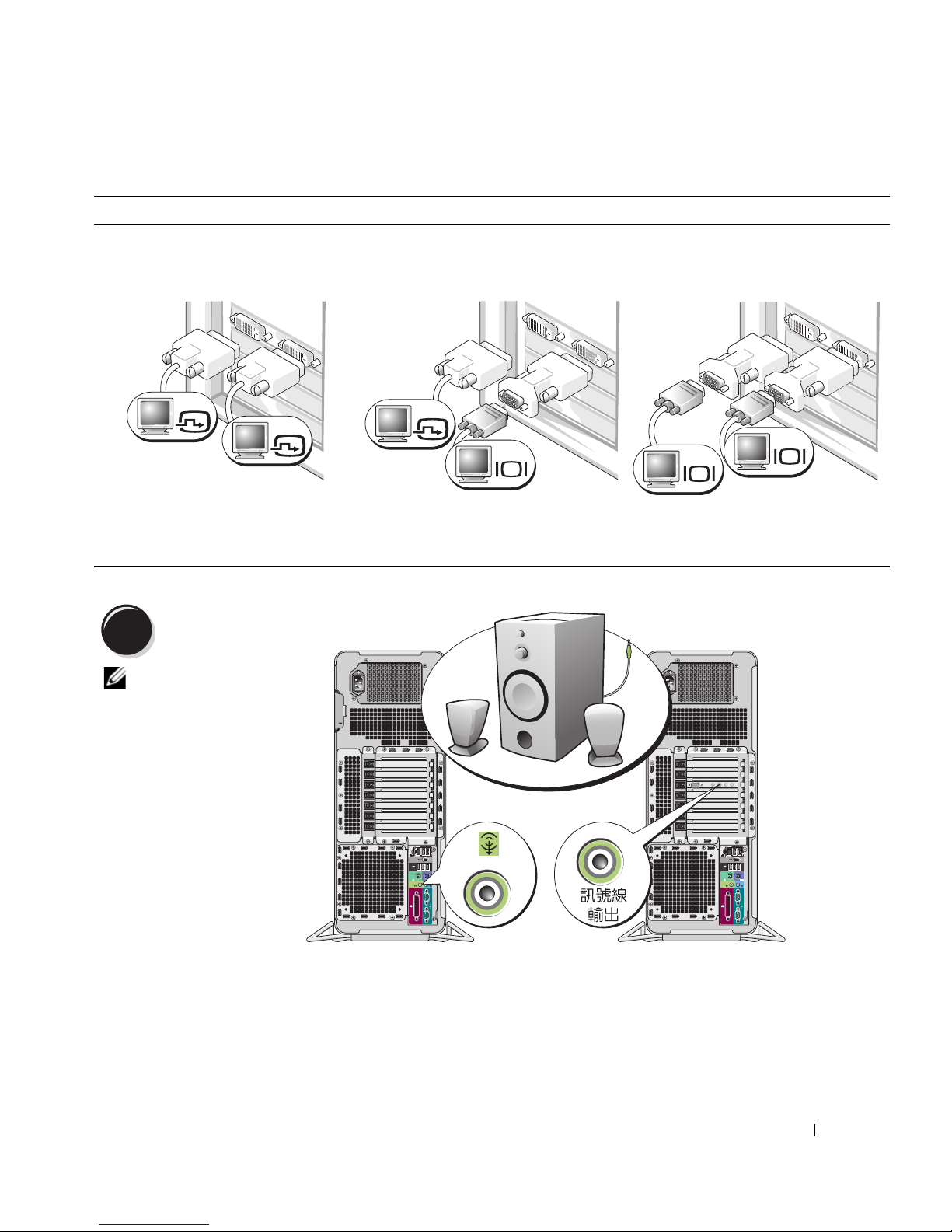
對於具有兩個 DVI 連接器的支援雙顯示器的插卡
兩個 DVI 連接器:
DVI
DVI
使用 DVI 連接器將電腦連接至一台或
兩台 DVI 顯示器。
4
連接喇叭。
註: 如果您的電腦已
安裝音效卡,請將喇
叭連接至該音效卡。
兩個 DVI 連接器搭配一個 VGA 配接
器:
DVI
VGA
使用 VGA 配接器將一台 VGA 顯示器
連接至電腦的兩個 DVI 連接器中的一
個
兩個 DVI 連接器搭配兩個 VGA 配接
器:
VGA
VGA
使用兩個 VGA 配接器將兩台 VGA 顯
示器連接至電腦的 DVI 連接器
快速參考指南 55
Page 56
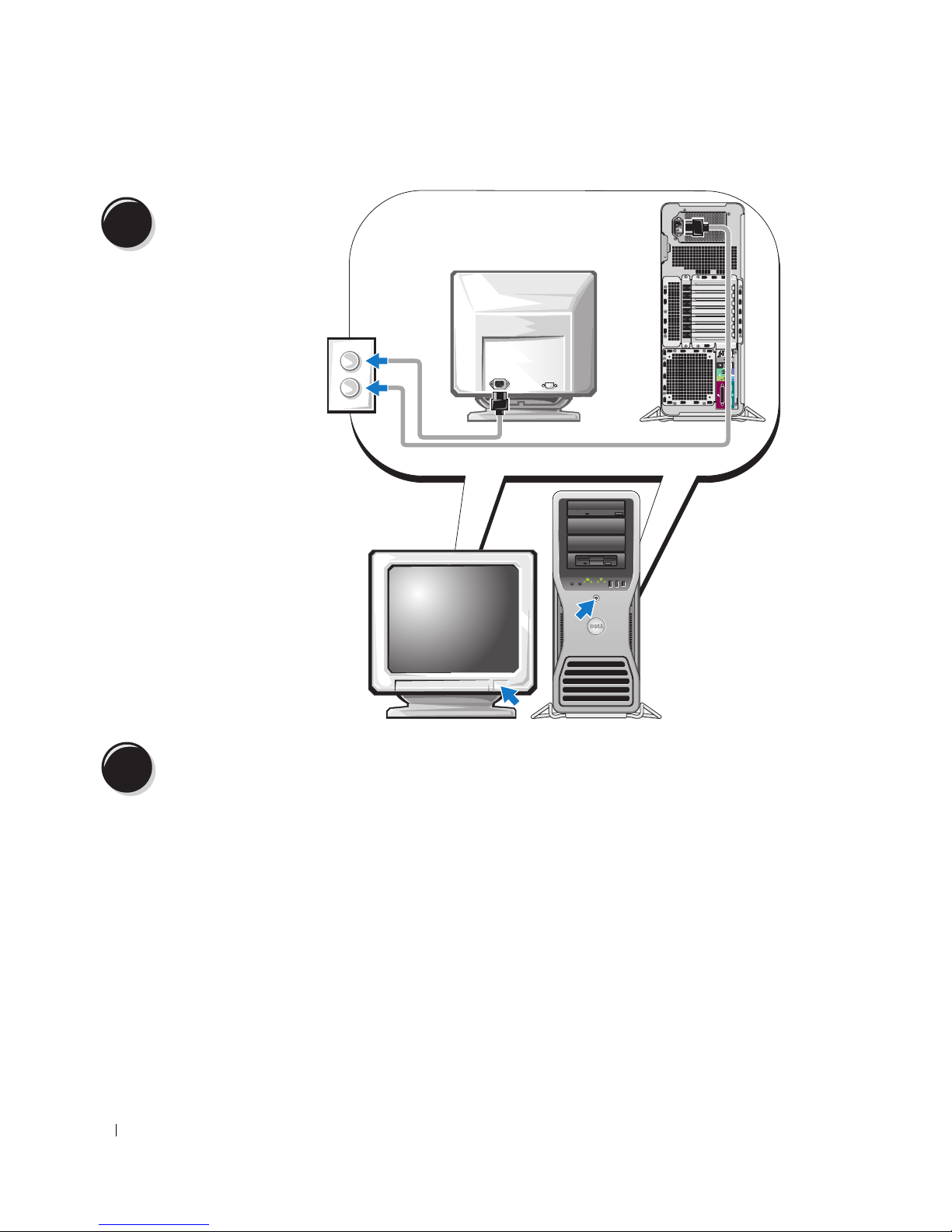
5
連接電源線並開啟電
腦及顯示器。
6
在安裝任何非電腦隨附的裝置或軟體之前,請閱讀軟體或裝置隨附的說明文件或與供應商聯絡,以確
認該軟體或裝置與您的電腦及作業系統相容。
現在您已完成電腦的安裝。
56 快速參考指南
安裝其他軟體或裝置。
Page 57
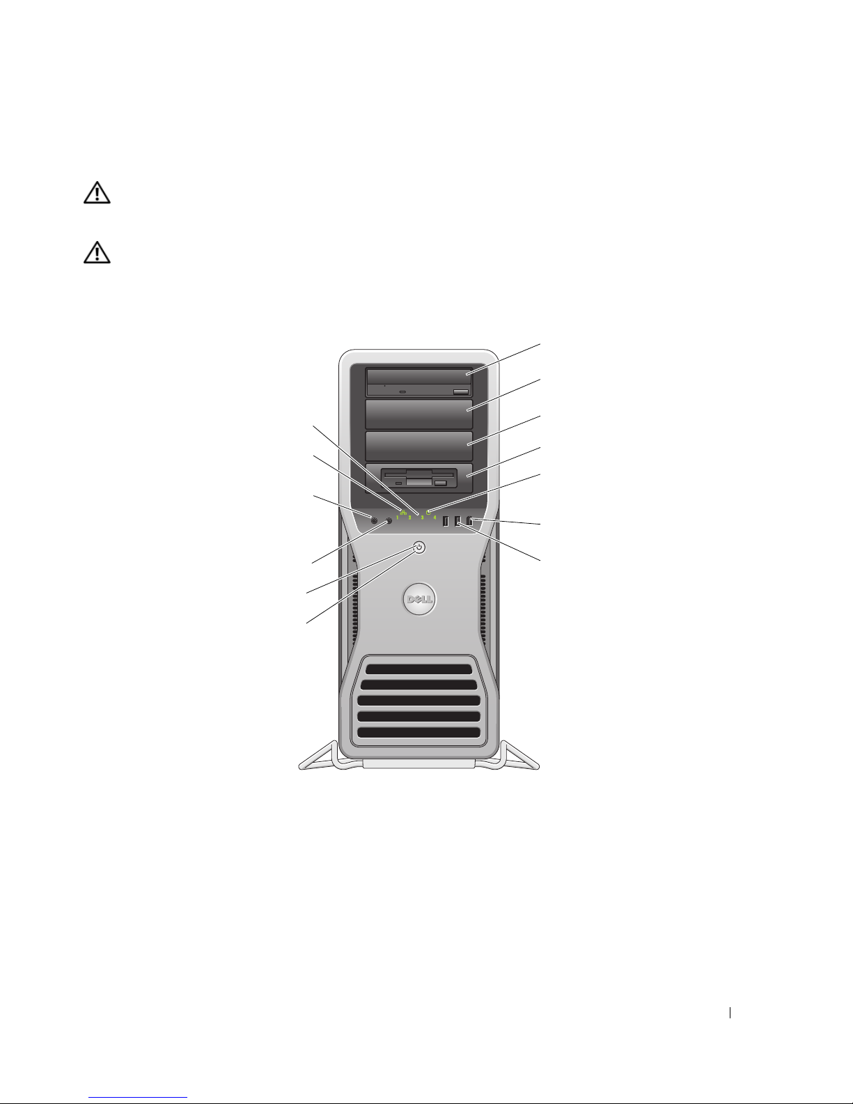
關於您的電腦
1
警示: 您的電腦很重 ( 估計至少重 55 lb),難以進行操控。 嘗試提起、移動或使其傾斜之前,請尋求援
助;此電腦需要兩個人才能提起。 請務必正確地提起電腦以避免受傷;提起電腦時請不要俯身。 請參閱
《產品資訊指南》以獲得其他重要的安全資訊。
警示: 垂直放置電腦之前,請安裝電腦腳架。 如果垂直放置電腦之前未安裝腳架,則可能使電腦翻倒,
並可能導致身體受傷或損壞電腦。
前視圖
2
13
12
11
10
9
8
3
4
5
6
7
快速參考指南 57
Page 58

1-3
5.25 吋磁碟機支架 可將 CD/DVD 光碟機、媒體讀卡器、軟式磁碟機或 SATA 硬碟機置於 5.25 吋
磁碟機支架承載器中。
註: 磁碟機承載器僅適用於 5.25 吋磁碟機支架。 軟式磁碟機 / 媒體讀卡器承載
器與硬碟機承載器不可互換。
4
具有特定 3.5 吋磁碟機
面板的 5.25 吋磁碟機支
架
可將 CD/DVD 光碟機、媒體讀卡器、軟式磁碟機或 SATA 硬碟機置於 5.25 吋
磁碟機支架承載器中。 此處顯示的磁碟機面板僅適用於軟式磁碟機或媒體讀
卡器;它可安裝於四個 5.25 吋磁碟機支架中任何一個的前部。 若要獲得更多
資訊,請參閱 《使用者指南》。
註: 磁碟機承載器僅適用於 5.25 吋磁碟機支架。 軟式磁碟機 / 媒體讀卡器承載
器與硬碟機承載器不可互換。
5
硬碟機活動指示燈 當電腦從硬碟機讀取資料或將資料寫入硬碟機時,硬碟機指示燈會亮起。 當
如 CD 播放機之類的裝置作業時,該指示燈可能也會亮起。
6
IEEE 1394 連接器 使用 IEEE 1394 連接器連接高速資料裝置 ( 例如數位攝影機和外接式儲存裝
置 )。
7
USB 2.0 連接器 (2) 請使用前面的 USB 連接器連接偶爾需要連接的裝置 ( 例如快閃記憶體鑰匙、
相機或可啟動 USB 裝置 ) ( 請參閱 《使用者指南》以獲得更多資訊 )。
建議您使用背面的 USB 連接器連接通常需要保持連接的裝置,例如印表機和
鍵盤。
8
電源按鈕 按此按鈕可以開啟電腦。
注意事項: 為避免遺失資料,請勿使用電源按鈕來關閉電腦, 而應執
行作業系統關機程序。
註: 電源按鈕也可以用來喚醒系統,或使系統處於省電狀態。 請參閱 《使用
者指南》以獲得更多資訊。
9
電源指示燈 電源指示燈亮起和閃爍或保持穩定顏色,可以表示不同的狀態:
•
未亮起 ─ 電腦已關閉或處於休眠模式。
•
綠色穩定 ─ 電腦處於正常的作業狀態。
•
綠色閃爍 ─ 電腦處於省電狀態。
•
琥珀色閃爍或穩定亮起 ─ 請參閱 《使用者指南》中的 「電源問題」。
若要結束省電狀態,請按電源按鈕或者使用鍵盤或滑鼠 ( 如果在 Windows 裝
置管理員中將其組態為喚醒裝置 )。 若要獲得有關睡眠狀態以及結束省電狀態
的更多資訊,請參閱 《使用者指南》。
請參閱第 74 頁的 「診斷指示燈」,以獲得相關指示燈代碼說明,從而協助您
排除電腦問題。
10
麥克風連接器
11
耳機連接器 使用耳機連接器連接耳機。
12
網路連結指示燈 當 10 Mbps、100 Mbps 或 1000 Mbps ( 或 1 Gbps) 網路和電腦之間的連接狀態
13
診斷指示燈 (4) 這些指示燈可以幫助您基於診斷故障碼排除電腦問題。 若要獲得更多資訊,
使用麥克風連接器連接個人電腦麥克風,以將語音或音樂輸入音效或電話程式。
良好時,網路連結指示燈將會亮起。
請參閱第 74 頁的 「診斷指示燈」。
58 快速參考指南
Page 59
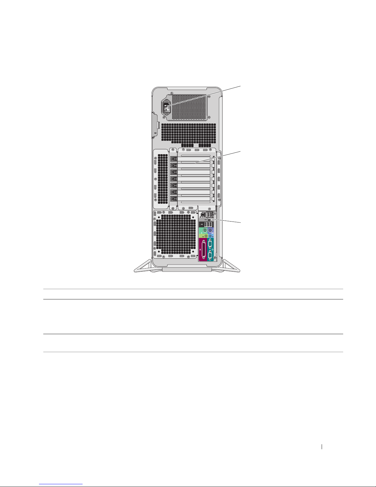
後視圖
1
2
3
1
電源連接器 用於插入電源線。 此連接器的外觀與此處所畫的圖形可能會有所不同。
2
插卡插槽 用於存取任何已安裝的 PCI 卡、PCI-X 卡或 PCI Express 卡的連接器。
註: 中心的五個連接器插槽支援全長插卡: 一個 PCI、一個 PCI Express x16、
一個 PCI Express x8 ( 以 x4 模式連線 ) 和兩個 PCI-X 插槽;頂部和底部的連接器
插槽支援半長插卡: 兩個 PCI Express x8 插槽 ( 以 x4 模式連線 )
3
背面板連接器 用於將序列裝置、USB 裝置以及其他裝置連接至
頁的 「背面板連接器」 )。
相應的連接器
快速參考指南 59
( 請參閱第 60
Page 60
背面板連接器
1 234 6
57
13 12 11 10 89
1
並列連接器 用於將並列裝置 ( 如印表機 ) 連接至並列連接器。 如果是 USB 印表機,請將
其插入 USB 連接器。
註:
如果電腦偵測到某個已安裝的插卡包含組態為同一位址的並列連接器,則
內建的並列連接器會自動停用。
2
訊號線輸出 / 耳機連接器此綠色訊號線輸出連接器用於連接耳機和大多數具有內建放大器的喇叭。
在配有音效卡的電腦中,請使用該插卡上的連接器。
3
滑鼠連接器 此綠色滑鼠連接器用於連接標準滑鼠。 將滑鼠連接至電腦之前,請關閉電腦
和所有連接的裝置。 如果您使用 USB 滑鼠,請將其插入 USB 連接器。
如果您的電腦執行 Microsoft
必要的滑鼠驅動程式。
4
USB 2.0 連接器 (3)
5
連結完整性指示燈
6
網路配接器連接器 若要將電腦連接至網路或寬頻裝置,請將網路纜線的一端連接至網路插孔、
建議您使用前面的
匙、相機或可啟動
請使用背面的
•
綠色 ─
•
橘黃色 ─
•
黃色 ─
•
關閉 ─ 電腦未偵測到網路實體連線。
網路或寬頻裝置。 將網路纜線的另一端連接至電腦的網路配接器連接器。 聽
到卡嗒聲表示網路纜線已連接穩固。
10 Mbps
1000 Mbps (或 1 Gbps)
USB
USB
USB
連接器連接通常需要保持連接的裝置,例如印表機和鍵盤。
網路和電腦之間的連線狀態良好。
100 Mbps
連接器連接偶爾需要連接的裝置 (例如快閃記憶體鑰
裝置)。
網路和電腦之間的連線狀態良好。
註: 請勿將電話線插入網路連接器。
在配有附加網路連接器插卡的電腦上,當設定多個網路連線 ( 例如單獨內聯網
路和外聯網路 ) 時,使用插卡上的連接器和電腦背面的連接器。
建議您在網路中使用 Category 5 纜線和連接器。 如果您必須使用 Category 3 纜
線,請將網路速度強行設定為 10 Mbps 以確保可靠作業。
若要獲得更多資訊,請參閱 《使用者指南》。
®
Windows® XP 作業系統,則硬碟機上已安裝有
網路和電腦之間的連線狀態良好。
60 快速參考指南
Page 61

7
網路活動指示燈 當電腦傳送或接收網路資料時,此指示燈會呈黃色閃爍。 如果網路資訊流量
較大,該指示燈可能會呈現持續 「亮起」的狀態。
8
USB 2.0 連接器 (2)
9
IEEE 1394 連接器 使用 IEEE 1394 連接器連接高速資料裝置 ( 例如數位攝影機和外接式儲存裝
建議您使用前面的
匙、相機或可啟動
請使用背面的
USB
USB
連接器連接偶爾需要連接的裝置 (例如快閃記憶體鑰
USB
裝置)。
連接器連接通常需要保持連接的裝置,例如印表機和鍵盤。
置 )。
10
鍵盤連接器 如果您使用的是標準鍵盤,請將其插入紫色的鍵盤連接器。 如果是 USB 鍵
盤,請將其插入 USB 連接器。
11
訊號線來源連接器 此藍色訊號線來源連接器用於連接錄音 / 播放裝置,如卡帶播放機、CD 播放
機或 VCR。
在配有音效卡的電腦中,請使用該插卡上的連接器。
12
序列連接器 用於將序列裝置 ( 如掌上型裝置 ) 連接至序列埠。 如有必要,可透過系統設定
程式來修改此連接埠的位址 ( 請參閱 《使用者指南》以獲得更多資訊 )。
13
序列連接器 用於將序列裝置 ( 如掌上型裝置 ) 連接至序列埠。 如有必要,可透過系統設定
程式來修改此連接埠的位址 ( 請參閱 《使用者指南》以獲得更多資訊 )。
快速參考指南 61
Page 62
內部視圖
1
2
7
6
45
1
2
3
4
5
6
7
電源供應器
硬碟機支架
記憶體通風罩
注意事項: 記憶體通風罩將 ( 可選 ) 記
憶體提昇卡固定到位;其指旋螺絲必須
擰至足夠緊,才能固定提昇部件並避免
造成損壞。
前部風扇
插卡風扇
具有 3.5 吋磁碟機面板的 5.25 吋磁碟機支架
5.25 吋磁碟機支架
3
62 快速參考指南
Page 63
主機板元件
2 3456 9
1 8
7
10
11
33
32
31
12
13
14
15
16
17
18
19
20
30
21
26272829
232425
快速參考指南 63
22
Page 64

1
次處理器連接器 (CPU_1)
2
前部風扇連接器 (FAN_FRONT)
3
插卡固定框架風扇連接器 (FAN_CCAG)
4
內建喇叭連接器 (INT_SPKR)
5
電源連接器 (POWER2)
6
IDE 磁碟機連接器 (IDE)
7
密碼跳線 (PSWD)
8
輔助硬碟機 LED 連接器 (AUX_LED)
9
電池槽 (BATTERY)
10
SATA 連接器 (SATA_0、SATA_1、SATA_2)
11
RTC 重設跳線 (RTCRST)
12
主電源連接器 (POWER1)
13
硬碟機連接器 (HDD_3)
14
硬碟機連接器 (HDD_2)
15
硬碟機連接器 (HDD_1)
16
硬碟機連接器 (HDD_0)
17
硬碟機風扇 (FAN_HDD)
18
Flexbay 連接器 (USB)
19
軟式磁碟機 (DSKT)
20
前面板連接器 (FRONTPANEL)
21
前面板 1394 連接器 (FP1394)
22
外殼侵入接頭 (INTRUDER)
23
PCI Express x8 卡插槽,以 x4 模式連線
(SLOT7_PCIE)
24
PCI-X 卡插槽 (SLOT6_PCIX)
25
PCI-X 卡插槽 (SLOT5_PCIX)
26
PCI 卡插槽 (SLOT4_PCI)
註: 此插槽在雙圖形組態中不適用
27
PCI Express x8 卡插槽,以 x4 模式連線
(SLOT3_PCIE)
註: 在雙圖形組態中,圖形提昇部件上的此
插槽由 x16 插槽替換。 該插槽用於圖形卡。
28
PCI Express x16 卡插槽 (SLOT2_PCIE)
註: 此插槽在雙圖形組態中不適用
29
PCI Express x8 卡插槽,以 x4 模式連線
(SLOT1_PCIE)
註: 在雙圖形組態中,圖形提昇部件上的此
插槽由 x16 插槽替換。 該插槽用於圖形卡。
30
記憶體風扇連接器 (FAN_MEM)
31
白色記憶體模組連接器 (DIMM_1-4)
支援記憶體模組或記憶體模組提昇部件
32
黑色記憶體模組連接器 (DIMM_5-8)
僅在未安裝記憶體提昇卡時支援記憶體模組;
否則,它們必須保留為空
33
主處理器連接器 (CPU_0)
纜線顏色
裝置 顏色
硬碟機 ( 具有機載控制器 ) 藍色纜線
軟式磁碟機 黑色拉式彈片
CD/DVD 光碟機 橘黃色拉式彈片
64 快速參考指南
Page 65
找到您的 《使用者指南》
《使用者指南》包含有關電腦的其他資訊,例如:
•
技術規格
•
電腦的前視圖和後視圖,包括所有的可用連接器
•
電腦的內部視圖,包括主機板和連接器的詳細圖形
•
清潔電腦的說明
•
有關軟體功能 (例如
•
有關使用
•
有關卸下與安裝零件 (包括記憶體、插卡、磁碟機、微處理器和電池) 的說明
•
有關排除各種電腦問題的資訊
•
有關使用
•
有關如何與
您可以從硬碟機或
Microsoft Windows XP
Dell Diagnostics
Dell
Dell
Legacy Select
和重新安裝驅動程式的說明
公司聯絡的資訊
支援
Web
站台 (support.dell.com) 存取 《使用者指南》。
技術控制、使用密碼和系統設定程式選項) 的資訊
作業系統的秘訣及資訊
卸下機箱蓋
警示: 在您執行本章節中的任何程序之前,請遵循 《產品資訊指南》中的安全指示。
警示: 為防止觸電,在卸下機箱蓋之前,請務必從電源插座中拔下電腦電源線。
警示: 您的電腦很重 ( 估計至少重 55 lb),難以進行操控。 嘗試提起、移動或使其傾斜之前,請尋求援
助;此電腦需要兩個人才能提起。 請務必正確地提起電腦以避免受傷;提起電腦時請不要俯身。 請參閱
《產品資訊指南》以獲得其他重要的安全資訊。
警示: 應始終安裝電腦腳架,以確定獲得最大限度的系統穩定性。 如果未安裝腳架,則可能使電腦翻
倒,並可能導致身體受傷或損壞電腦。
注意事項: 為防止靜電損壞電腦內部元件,在觸摸電腦的任何電子元件之前,請先導去您身上的靜電。
您可以觸摸電腦未上漆的金屬表面,以導去身上的靜電。
1
按照 《使用者指南》之 「開始之前」中的程序進行操作。
注意事項: 如果在電腦執行時打開機箱蓋,則會導致在無警告的情況下關機,並導致開啟的程式遺失資
料。 卸下機箱蓋後,電腦的散熱系統無法正常作業。
2
如果您已安裝安全纜線,請將其從安全纜線孔拔下。
3
請在助手的協助下,小心地卸下電腦腳架 (請參閱 「卸下電腦腳架」)。
警示: 您的電腦很重 ( 估計至少重 55 lb),難以進行操控。 嘗試提起、移動或使其傾斜之前,請尋求援
助;此電腦需要兩個人才能提起。 請務必正確地提起電腦以避免受傷;提起電腦時請不要俯身。 請參閱
《產品資訊指南》以獲得其他重要的安全資訊。
警示: 應始終安裝電腦腳架,以確定獲得最大限度的系統穩定性。 如果未安裝腳架,則可能使電腦翻
倒,並可能導致身體受傷或損壞電腦。
注意事項: 請確定在水平的受保護的表面上工作,以避免刮傷電腦或放置電腦的表面。
快速參考指南 65
Page 66
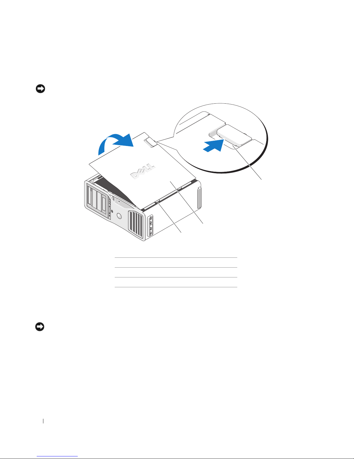
4
請在助手的協助下,小心地將電腦放置在平坦的表面上,使機箱蓋朝上。
5
向後拉動機箱蓋釋放閂鎖。
注意事項: 請確定桌面至少有 30 cm (1 ft) 的空間以放置卸下的機箱蓋。
2
3
1
1
機箱蓋釋放閂鎖
2
機箱蓋
3
機箱蓋鉸接
6
找到電腦邊緣的三個鉸接彈片。
7
握住電腦機箱蓋邊緣,並使用鉸接作為槓桿點向上轉動機箱蓋。
8
將機箱蓋從鉸接彈片釋放,並將其置於安全位置。
注意事項: 如果不安裝機箱蓋,則電腦的散熱系統無法正常作業。 請勿嘗試在重新安裝機箱蓋之前啟動
電腦。
66 快速參考指南
Page 67
電腦腳架
警示: 您的電腦很重 ( 估計至少重 55 lb),難以進行操控。 嘗試提起、移動或使其傾斜之前,請尋求援
助;此電腦需要兩個人才能提起。 請務必正確地提起電腦以避免受傷;提起電腦時請不要俯身。 請參閱
《產品資訊指南》以獲得其他重要的安全資訊。
警示: 應始終安裝電腦腳架,以確定獲得最大限度的系統穩定性。 如果未安裝腳架,則可能使電腦翻
倒,並可能導致身體受傷或損壞電腦。
警示: 在您執行本章節中的任何程序之前,請遵循 《產品資訊指南》中的安全指示。
警示: 為防止觸電,在卸下機箱蓋之前,請務必從電源插座中拔下電腦電源線。
注意事項: 為防止靜電損壞電腦內部元件,在觸摸電腦的任何電子元件之前,請先導去您身上的靜電。
您可以觸摸電腦未上漆的金屬表面,以導去身上的靜電。
連接電腦腳架
警示: 您的電腦很重 ( 估計至少重 55 lb),難以進行操控。 嘗試提起、移動或使其傾斜之前,請尋求援
助;此電腦需要兩個人才能提起。 請務必正確地提起電腦以避免受傷;提起電腦時請不要俯身。 請參閱
《產品資訊指南》以獲得其他重要的安全資訊。
警示: 應始終安裝電腦腳架,以確定獲得最大限度的系統穩定性。 如果未安裝腳架,則可能使電腦翻
倒,並可能導致身體受傷或損壞電腦。
1
按照 《使用者指南》之 「開始之前」中的程序進行操作。
2
如果您已安裝安全纜線,請將其從安全纜線孔拔下。
3
將腳架放置在電腦前面的地面上,以使腳架的前部和後部都接觸到地面。
如果腳架的前部和後部指向天花板,則腳架上下顛倒。
4
請確定定位導軌面向電腦。
如果定位導軌的指向背離電腦,則腳架前後顛倒。
快速參考指南 67
Page 68
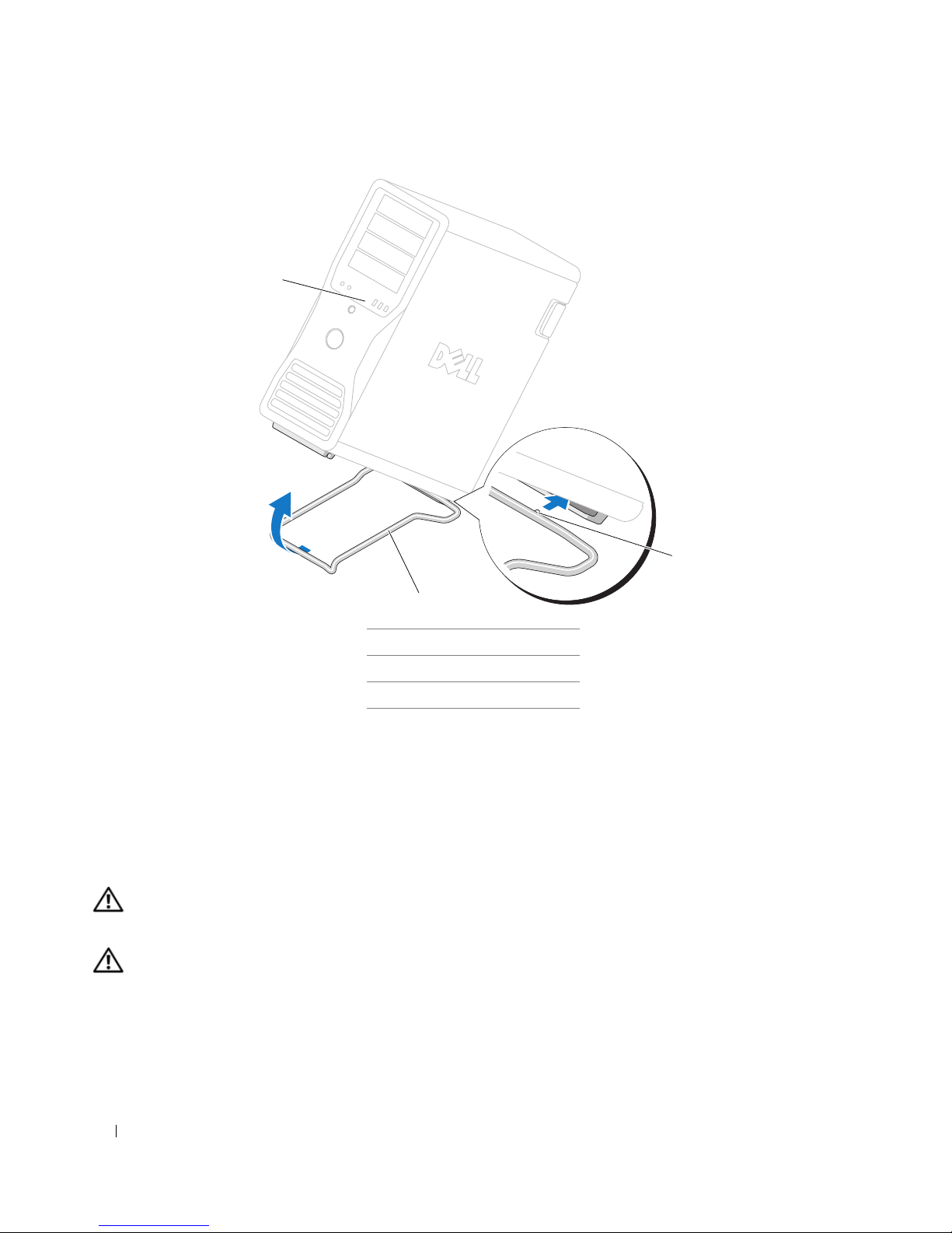
1
3
2
1
電腦
2
電腦腳架
3
定位導軌
5
將腳架的中心與電腦的中心對齊。
6
請在助手的協助下,小心地將電腦向後微微傾斜,直至有足夠的高度將腳架滑入電腦下面。
7
將腳架後部滑入電腦後腳處,並確定定位導軌滑入到位。
8
將腳架的前軸置於電腦前腳相應槽口的中心。
9
請小心地將電腦放下;腳架的前軸應卡入到位以承載整個電腦的重量。
卸下電腦腳架
警示: 您的電腦很重 ( 估計至少重 55 lb),難以進行操控。 嘗試提起、移動或使其傾斜之前,請尋求援
助;此電腦需要兩個人才能提起。 請務必正確地提起電腦以避免受傷;提起電腦時請不要俯身。 請參閱
《產品資訊指南》以獲得其他重要的安全資訊。
警示: 應始終安裝電腦腳架,以確定獲得最大限度的系統穩定性。 如果未安裝腳架,則可能使電腦翻
倒,並可能導致身體受傷或損壞電腦。
1
按照 《使用者指南》之 「開始之前」中的程序進行操作。
2
請在助手的協助下,小心地將電腦向後傾斜,使其與地面形成極小的角度。
3
朝地面方向向下拉動電腦腳架前部,使其脫離電腦前部。
4
朝電腦前部拉動電腦腳架,直至腳架脫離電腦。
68 快速參考指南
Page 69

維護您的電腦
為有助於維護您的電腦,請遵循以下建議:
•
為避免遺失或損壞資料,當硬碟機指示燈亮起時切勿關閉電腦。
•
使用防毒軟體定期執行病毒掃描。
•
定期刪除不必要的檔案並對磁碟機執行片段重組,以管理硬碟機空間。
•
定期備份檔案。
•
定期清潔顯示器螢幕、滑鼠和鍵盤 (請參閱 《使用者指南》以獲得更多資訊)。
解決問題
故障排除秘訣
排除電腦故障時,請執行以下檢查:
•
如果您在問題出現之前新增或卸下某個零件,請檢查安裝步驟並確定該零件安裝正確。
•
如果某個週邊裝置無法作業,請確定該裝置已正確連接。
•
如果螢幕顯示錯誤訊息,請記下此確切訊息。 該訊息可能會協助技術支援人員診斷和解決問題。
•
如果在某個程式中出現錯誤訊息,請參閱該程式的說明文件。
•
如果故障排除章節建議的動作是參閱 《使用者指南》中的某個章節,請移往 support.dell.com (
有必要,請在另一部電腦上進行
)
以存取 《使用者指南》。
如
解決軟體和硬體不相容問題
如果在作業系統安裝期間系統未偵測到裝置,或者偵測到裝置但其組態不正確,您可以使用硬體疑難
排解來解決不相容問題。
若要使用硬體疑難排解解決不相容問題,請:
1
單按開始按鈕,然後單按說明及支援。
2
在搜尋欄位中,鍵入
3
在搜尋結果清單中,單按硬體疑難排解。
4
在硬體疑難排解清單中,單按我的電腦上有硬體衝突的情形需要解決,然後單按下一步。
硬體疑難排解
,然後單按箭頭開始搜尋。
使用 Microsoft® Windows® XP 系統還原
如果對硬體、軟體或其他系統設定所作的變更使電腦處於不理想的作業狀態,
作業系統提供的系統還原可讓您將電腦返回至先前的作業狀態 (不影響資料檔案)。 請參閱
說明及支援中心 (參閱第
注意事項: 請定期備份您的資料檔案。 系統還原不能監測資料檔案,也無法對其進行恢復。
49
頁的「查找資訊」),以獲得有關使用系統還原的資訊。
Microsoft Windows XP
Windows
快速參考指南 69
Page 70

建立還原點
1
單按開始按鈕,然後單按說明及支援。
2
單按系統還原。
3
依螢幕指示操作。
將電腦還原至先前的作業狀態
注意事項: 將電腦還原至先前的作業狀態之前,請儲存並關閉所有開啟的檔案,並結束所有開啟的程
式。 在系統還原完成之前,請勿變更、開啟或刪除任何檔案或程式。
1
單按開始按鈕,指向所有程式
2
確定已選擇將電腦還原到較早的時間點,然後單按下一步。
3
單按希望將電腦還原到的日期。
選取一個還原點螢幕將提供一份日曆,供您查看與選擇還原點。
字類型顯示。
4
選擇一個還原點,然後單按下一步。
→
附屬應用程式
→
系統工具,然後單按系統還原。
所有可用還原點的日期將以黑體
如果日曆只有一個還原點,則自動選定此還原點。 如果具有兩個或兩個以上的還原點,請單按您
希望使用的還原點。
5
單按下一步。
系統還原完成資料收集後,螢幕上將會出現還原完成螢幕,然後電腦將重新啟動。
6
電腦重新啟動後,請單按確定。
若要變更還原點,您可以使用不同的還原點重複這些步驟,或者復原還原。
復原上一次系統還原
注意事項: 在復原上一次系統還原之前,請儲存並關閉所有開啟的檔案,結束所有開啟的程式。 在系統
還原完成之前,請勿變更、開啟或刪除任何檔案或程式。
1
單按開始按鈕,指向所有程式
2
單按復原上次還原並單按下一步。
3
單按下一步。
螢幕上將會出現系統還原螢幕,然後電腦將重新啟動。
4
電腦重新啟動後,請單按確定。
啟用系統還原
當您重新安裝
Windows XP
時,若可用硬碟空間小於
→
附屬應用程式
→
系統工具,然後單按系統還原。
200 MB
,則系統還原功能將會自動停用。 若要查
看系統還原功能是否啟用,請:
1
單按開始按鈕,然後單按控制台。
2
單按效能及維護。
70 快速參考指南
Page 71

3
單按系統。
4
單按系統還原標籤。
5
確定已取消勾選關閉所有磁碟上的系統還原。
使用上一次已知的正確組態
1
重新啟動電腦,然後當顯示
的作業系統
2
反白顯示 Last Known Good Configuration (
)
訊息時按
Please select the operating system to start (
<F8>
鍵。
上一次所知道的正確組態),按
鍵然後在系統提示時選擇作業系統。
協助解決其他裝置或軟體衝突的其他選擇
注意事項: 以下程序會清除硬碟機上的所有資訊。
•
使用作業系統安裝指南和作業系統
CD
重新安裝作業系統。
在重新安裝作業系統期間,您可以選擇刪除現有分割區並重新為硬碟機製作格式。
•
使用 Drivers and Utilities
CD 從晶片組開始,重新安裝所有驅動程式。
Dell Diagnostics
警示: 在您執行本章節中的任何程序之前,請遵循 《產品資訊指南》中的安全指示。
<Enter>
請選擇要啟動
鍵,按
<l>
何時使用 Dell Diagnostics
如果您的電腦出現問題,請在與
中的檢查步驟,並執行
Dell Diagnostics
Dell
公司聯絡以尋求技術援助之前,先執行第
。
69
頁的「解決問題」
建議您在開始之前先列印這些步驟。
注意事項: Dell Diagnostics 僅能在 Dell 電腦上使用。 如果您在其他電腦上使用本程式,可能會使電腦作
出不正確的回應或導致錯誤訊息的出現。
Dell Diagnostics
•
快速檢查或廣泛測試一個或所有裝置
•
選擇執行測試的次數
•
顯示或列印測試結果,或將結果存入檔案
•
在偵測到錯誤時暫停測試;或在出現一定數目的錯誤時終止測試
•
存取描述測試程式以及如何執行這些測試程式的線上說明螢幕
•
閱讀通知您測試是否已成功完成的狀態訊息
•
接收偵測到問題時的錯誤訊息
允許您執行以下作業:
快速參考指南 71
Page 72

從硬碟機啟動 Dell Diagnostics
1
開啟 (或重新啟動) 電腦。
2
當螢幕上出現
註: 如果您看到表明未找到診斷公用程式分割區的訊息,請參閱第 72 頁的 「從 Drivers and Utilities CD 啟
動 Dell Diagnostics」。
DELL™
徽標時,請立即按
<F12>
鍵。
如果您等待過久,並且螢幕上已出現作業系統徽標,則請繼續等待,直至看到
Windows
桌面。 然後關閉電腦,並再試一次。 若要獲得有關關閉電腦的更多資訊,請參閱 《使
Microsoft
用者指南》。
3
當螢幕上顯示啟動裝置清單時,請反白顯示 Boot to Utility Partition (
按
<Enter>
4
當螢幕上出現
鍵。
Dell Diagnostics
Main Menu (
主選單) 時,請選擇您要執行的測試程式。 若要獲得
啟動至公用程式分割區)
有關測試程式的更多資訊,請參閱 《使用者指南》。
從 Drivers and Utilities CD 啟動 Dell Diagnostics
註: Drivers and Utilities CD 是可選的,可能並非隨附於所有電腦。
1
插入 Drivers and Utilities
2
關閉電腦
當螢幕上出現
DELL
如果您等待過久,並且螢幕上已出現
CD
。
徽標時,請立即按
Windows
<F12>
鍵。
徽標,請繼續等待,直至看到
Windows
後關閉電腦,並再試一次。
註: 之後的步驟僅單次變更開機順序。 在下一次啟動時,電腦會按照系統設定程式中指定的裝置進行啟
動。
3
當螢幕上出現啟動裝置清單時,請反白顯示 Onboard or USB CD-ROM Drive (
)
並按
機
<Enter>
鍵。
機載或
USB
並
桌面。 然
光碟
4
從
CD
啟動選單中選擇 Onboard or USB CD-ROM Drive (
5
從螢幕上顯示的選單中選擇 Boot from CD-ROM (從 CD-ROM
6
鍵入
1
以啟動
7
選擇選項以啟動
8
從編號清單中選擇 Run the 32 Bit Dell Diagnostics (
ResourceCD
Dell Diagnostics
個版本,請選擇適用於您電腦的版本。
9
當螢幕上出現
Dell Diagnostics
在開始測試之前
警示: 在您執行本章節中的任何程序之前,請遵循 《產品資訊指南》中的安全指示。
•
如果電腦已連接印表機,請開啟印表機。
•
進入系統設定程式,檢查電腦的組態資訊,並啟用電腦的所有元件和裝置 (例如連接器)。
72 快速參考指南
選單。
,並按
Main Menu (
<Enter>
主選單)
機載或
USB
啟動)
光碟機) 選項。
選項。
鍵。
執行
32
位元
Dell Diagnostics)。
時,請選擇您要執行的測試程式。
如果列出多
Page 73

嗶聲代碼
如果顯示器無法顯示錯誤或問題,您的電腦可能會在啟動期間發出一系列嗶聲。 這一系列嗶聲稱為嗶
聲代碼,用來識別發生的問題。
後又一次嗶聲組成。
此嗶聲代碼告訴您,電腦記憶體出現問題。
如果電腦在啟動期間發出嗶聲,請:
1
將嗶聲代碼記錄在《使用者指南》中的 「診斷核對清單」上。
2
執行
Dell Diagnostics
3
請與
Dell
公司聯絡以尋求技術援助。
代碼原因
1-1-2
1-1-3
1-1-4
1-2-1
1-2-2
1-2-3
1-3
微處理器暫存器發生故障
NVRAM
ROM BIOS
可程式設計的間隔計時器發生故障
DMA
DMA
影像記憶體測試失敗
一種可能的嗶聲代碼 (代碼
,以識別可能更為嚴重的原因。
讀/寫故障
總和檢查失敗
起始作業失敗
頁暫存器讀/寫失敗
1-3-1)
由一次嗶聲,急促的三次嗶聲,然
1-3-1 至 2-4-4
1-3-2
3-1-1
3-1-2
3-1-3
3-1-4
3-2-2
3-2-4
3-3-1
3-3-2
3-3-4
3-4-1
3-4-2
3-4-3
4-2-1
4-2-2
未能正確識別或使用記憶體
記憶體問題
從屬
DMA
暫存器發生故障
主
DMA
暫存器發生故障
主岔斷屏蔽暫存器發生故障
從屬岔斷屏蔽暫存器發生故障
岔斷向量載入發生故障
鍵盤控制器測試失敗
NVRAM
無效的
影像記憶體測試失敗
螢幕起始作業發生故障
螢幕馳返失敗
搜尋影像
無計時器計時訊號
關機失敗
斷電
NVRAM
ROM
組態
失敗
快速參考指南 73
Page 74
代碼原因
4-2-3
4-2-4
4-3-1
4-3-3
4-3-4
4-4-1
4-4-2
4-4-3
4-4-4
閘發生故障
A20
保護模式下出現未預期的岔斷
在
0FFFFh
計時器晶片
小時計時時鐘停止
24
序列埠或並列埠測試失敗
將代碼解壓縮到陰影記憶體失敗
數學輔助處理器測試失敗
快取記憶體測試失敗
位址以上的記憶體發生故障
2
號計數器發生故障
錯誤訊息
註: 如果訊息沒有在清單上列出,請參閱作業系統或訊息顯示時所執行的程式之說明文件。
如果在啟動期間發生錯誤,顯示器上將顯示一條訊息,用以標識該問題。 請參閱 《使用者指南》中的
「錯誤訊息」,以獲得有關解決任何問題的建議。
診斷指示燈
警示: 在您執行本章節中的任何程序之前,請遵循 《產品資訊指南》中的安全指示。
為協助您排除故障,您電腦的前面板上有四個指示燈,分別標為「1」、「2」、「3」和 「4」。 這些指
示燈可能 「熄滅」或顯示為綠色。
式以及電源按鈕樣式可協助識別問題。
電腦正常啟動時,指示燈會閃爍。 如果電腦出現故障,則指示燈樣
這些指示燈還指示睡眠狀態。
執行 POST 之前的診斷指示燈代碼
診斷指示燈 電源指示燈問題說明 建議的解決方案
熄滅 電腦未接通電源。 將電腦連接至電源插座。 請確定前面板電源
指示燈亮起。 如果電源指示燈未亮起,請確
定電腦已連接至作業正常的電源插座,然後
按電源按鈕。
如果問題仍未解決,請與 Dell 公司聯絡以尋
求技術援助。
74 快速參考指南
Page 75
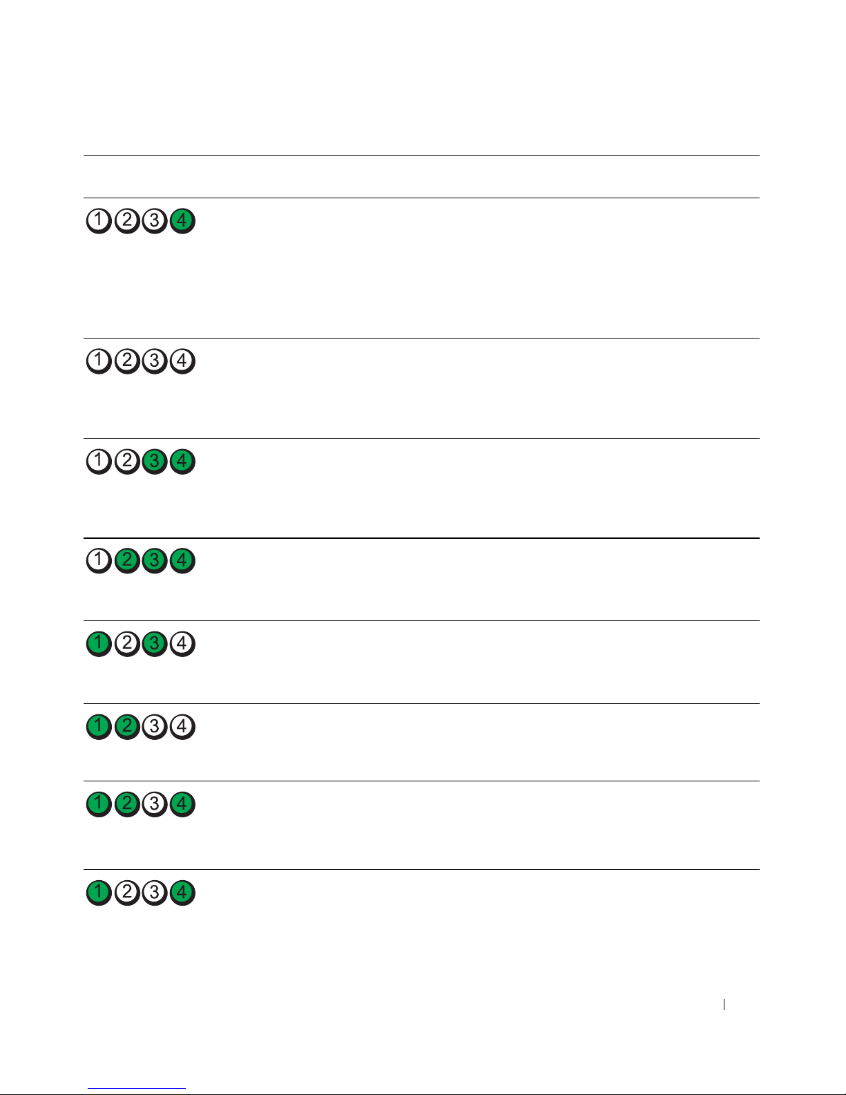
診斷指示燈 電源指示燈問題說明 建議的解決方案
( 閃爍 )
熄滅 電腦處於正常的關閉狀態;
電腦已連接至電源插座。
綠色閃爍 電腦處於省電或 「睡眠」狀
態。
綠色閃爍 電腦處於省電或 「睡眠」狀
態。
琥珀色 BIOS 未執行。
按下電源按鈕以開啟電腦。
如果電腦未開啟,請確定前面板電源指示燈
亮起。 如果電源指示燈未亮起,請確定電腦
已連接至作業正常的電源插座,然後按電源
按鈕。
如果問題仍未解決,請與 Dell 公司聯絡以尋
求技術援助。
使用其中一種適當的方法來 「喚醒」電腦。
請參閱 《使用者指南》中的 「進階功能」。
如果問題未解決且您正嘗試使用 USB 滑鼠或
鍵盤來喚醒電腦,請改用作業正常的 PS/2 滑
鼠或鍵盤來喚醒電腦。
使用其中一種適當的方法來 「喚醒」電腦。
請參閱 《使用者指南》中的 「進階功能」。
如果問題未解決且您正嘗試使用 USB 滑鼠或
鍵盤來喚醒電腦,請改用作業正常的 PS/2 滑
鼠或鍵盤來喚醒電腦。
請確定處理器已正確安插,然後重新啟動電
請參閱 《使用者指南》中的 「處理器」。
腦。
如果問題仍未解決,請與 Dell 公司聯絡以尋
求技術援助。
( 閃爍 )
( 閃爍 )
( 閃爍 )
( 閃爍 )
琥珀色閃爍電源供應器或電源線可能發
生故障。
請執行 《使用者指南》之 「電源問題」中的
程序。
如果問題仍未解決,請與 Dell 公司聯絡以尋
求技術援助。
琥珀色 主機板可能發生故障。 請與 Dell 公司聯絡尋求技術援助。
琥珀色 存在處理器不相符的問題。 請執行 《使用者指南》之 「處理器問題」中
的程序。
琥珀色 偵測到插入式元件 ( 例如圖
形提昇卡或記憶體提昇卡 )
可能已發生故障。
確認任何所需的電源線均已連接至記憶體提
昇卡和圖形提昇卡。
請執行 《使用者指南》之 「電源問題」中的
程序。
快速參考指南 75
Page 76
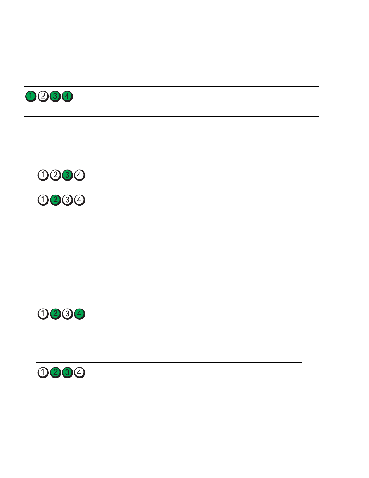
診斷指示燈 電源指示燈問題說明 建議的解決方案
琥珀色
電源供應器可能已發生故障。
確認兩根電源供應器纜線均已插入母板。
( 閃爍 )
POST 期間的診斷指示燈代碼
電源指示燈呈穩定的綠色,指示執行 POST 期間的診斷指示燈代碼。
指示燈顯示方式 問題說明 建議的解決方案
處理器可能發生故障。 重新安裝處理器並重新啟動電腦。
擴充卡可能發生故障。
1
卸下插卡 (不是圖形卡),然後重新
啟動電腦,以確定是否存在衝突。
2
如果問題仍然存在,請重新安裝卸
下的插卡,並卸下另一個插卡,然
後重新啟動電腦。
3
對每一個插卡重複此程序。如果電
腦正常啟動,則表明從電腦卸下的
最後一個插卡是衝突來源,請排除
故障
和硬體不相容問題」
4
每次將一個插卡移至另一個
槽,並在每次移動後重新啟動電腦。
5
如果問題仍然存在,請與
聯絡
(
請參閱第
。
69
頁的 「解決軟體
)
。
Dell
PCI
公司
插
圖形卡可能發生故障。
軟式磁碟機或硬碟機可能發生故障。 重新接插所有電源線或資料纜線,並
76 快速參考指南
1
如果電腦配有圖形卡,請卸下此圖
形卡,並重新安裝,然後重新啟動
電腦。
2
如果問題仍然存在,請安裝可正常
作業的圖形卡,然後重新啟動電腦。
3
如果問題仍然存在,或電腦具有內
Dell
建圖形,請與
公司聯絡
。
重新啟動電腦。
Page 77
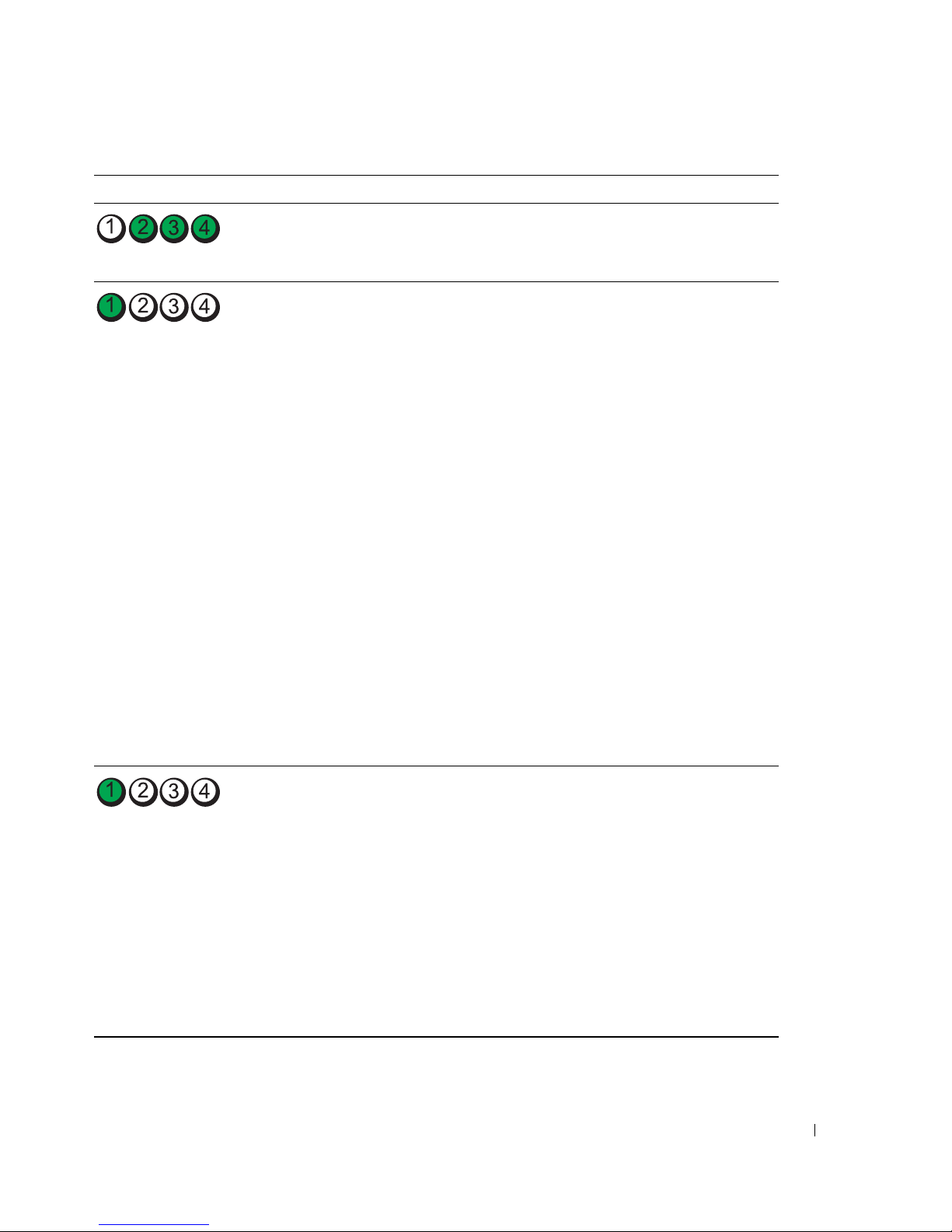
指示燈顯示方式 問題說明 建議的解決方案
USB 可能發生故障。 重新安裝所有 USB 裝置,檢查纜線連
接狀況,然後重新啟動電腦。
未偵測到記憶體模組。
1
重新接插記憶體模組,以確定電腦
正在與記憶體順利進行通訊。
2
重新啟動電腦。
3
如果問題仍然存在,請卸下所有記憶
體模組,然後在記憶體模組連接器
DIMM_1
4
重新啟動電腦。
中安裝一個記憶體模組。
螢幕上將顯示一條訊息,表明由於
您的記憶體不配對,導致系統效能
和錯誤更正功能降低
5
按
<F1>
6
執行
用者指南》以獲得更多資訊。
7
如果記憶體模組通過測試,請關閉
鍵以啟動至作業系統。
Dell Diagnostics。
請參閱 《使
電腦,卸下記憶體模組,然後對其
餘記憶體模組重複進行此步驟,直
至在啟動或診斷程式測試過程中發
生記憶體錯誤。
如果第一個記憶體模組經測試有故
障,則請對其餘的模組重複進行此
步驟,以確定其餘模組無故障。
8
識別出有故障的記憶體模組後,請
Dell
與
公司聯絡以便更換
。
未偵測到記憶體模組。
•
如果安裝有一個記憶體模組,請重
新安裝它,然後重新啟動電腦。
•
如果安裝有兩個或更多記憶體模組,
請卸下這些模組,並重新安裝一個
模組,然後重新啟動電腦。
如果電
腦正常啟動,請重新安裝另一個模
繼續執行此程序,直至識別出
組。
有故障的模組,或重新安裝所有模
組均未發生故障。
•
如果可以,請在電腦中安裝作業正
常的相同類型記憶體。
•
如果問題仍然存在,請與
Dell
公司
聯絡。
快速參考指南 77
Page 78
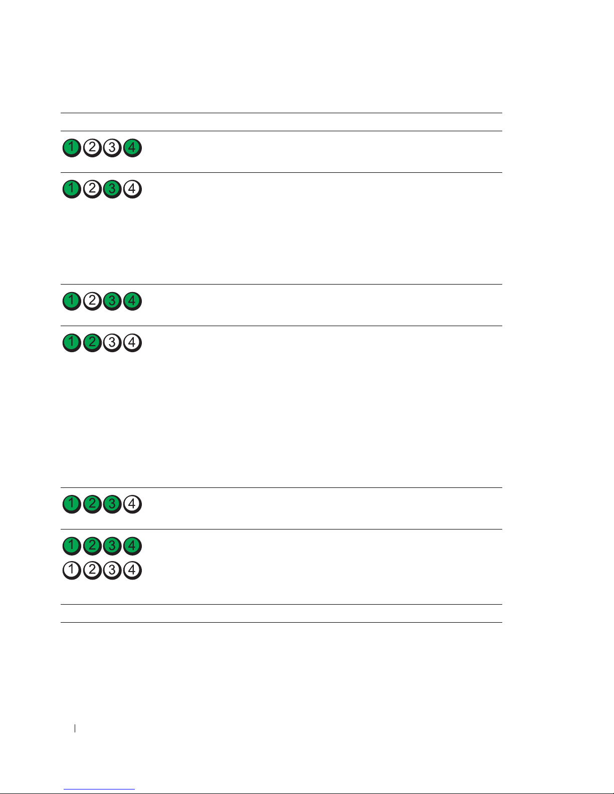
指示燈顯示方式 問題說明 建議的解決方案
主機板發生故障。 請與 Dell
偵測到記憶體模組,但存在記憶體組
態或相容性錯誤。
•
請確定記憶體模組/記憶體連接器沒
有特殊的安裝要求。
•
確認您要安裝的記憶體模組與電腦
相容。
重新安裝記憶體模組,然後重新啟
•
公司聯絡
以尋求技術援助
動電腦。
•
如果問題仍然存在,請與
Dell
公司
聯絡。
常規系統活動先於影像起始作業執行。 注意您的顯示器是否有螢幕訊息。
擴充卡可能發生故障。
1
卸下插卡 (不是圖形卡),然後重新
啟動電腦,以確定是否存在衝突。
2
如果問題仍然存在,請重新安裝卸
下的插卡,並卸下另一個插卡,然
後重新啟動電腦。
3
對每一個插卡重複此程序。如果電
腦正常啟動,則表明從電腦卸下的
最後一個插卡是衝突來源,請排除
(
請參閱第
故障
和硬體不相容問題」
4
如果問題仍然存在,請與
69
頁的 「解決軟體
)
。
Dell
公司
聯絡。
。
常規系統活動先於影像起始作業執行。 注意您的顯示器是否有螢幕訊息。
執行 POST 後,電腦處於正常的作業
狀態。
註: 診斷指示燈短暫地閃爍;它們在
電腦成功啟動至作業系統後熄滅。
78 快速參考指南
無。
Page 79

常見問題
我該如何 ... 解決方案 在哪裡可以找到其他資訊
將我的電腦設定為使用兩台顯示
器?
在顯示器纜線連接器看起來與電
腦背面的連接器不相匹配時連接
顯示器?
連接喇叭? 如果安裝有音效卡,請將喇叭連接
尋找 USB 或 IEEE 1394 裝置相應
的連接器?
如果您的電腦具有所需的支援雙顯
示器設定的圖形卡,那麼請在包裝
箱內尋找 Y 形纜線。 Y 形纜線的一
端有一個單獨的連接器 ( 將該連接
器連接至背面板上 ),而另一端則
分叉為兩個連接器 ( 將這兩個連接
器連接至顯示器纜線 )。
如果您的圖形卡具有 DVI 連接器但
您的顯示器使用的卻是 VGA 連接
器,那麼您需要使用配接器。 包裝
箱中應包含配接器。
至該插卡上的連接器。請參閱第 52
頁的 「安裝您的電腦」。
您的電腦有八個 USB 連接器 ( 前面
板上有兩個,內部有一個,背面板
上有五個 ),以及在前面板和背面
板上各一個 IEEE 1394 連接器。 若
要獲得有關 IEEE 1394 卡的更多資
訊,請參閱 《使用者指南》。
請參閱第 52 頁的 「安裝您的電
腦」,以獲得有關將雙顯示器連接
至電腦的資訊。
請參閱第 52 頁的 「安裝您的電
腦」,以獲得有關將顯示器連接至
電腦的資訊。 若要獲得更多資訊,
請與 Dell 公司聯絡。 若要獲得有關
與 Dell 公司聯絡的資訊,請參閱
《使用者指南》。
請參閱喇叭隨附的說明文件,以獲
得更多資訊。
請參閱第 57 頁的 「關於您的電
腦」以獲得電腦的前視圖及後視圖
圖解。
若要獲得有關找到 《使用者指南》
的說明,請參閱第 49 頁的 「查找
資訊」。
找到有關電腦硬體及其他技術規
格的資訊?
尋找電腦的說明文件? 有以下說明文件可用於您的電腦:
《使用者指南》中包含一個規格
表,其中提供了有關電腦及硬體的
更多詳細資訊。 若要找到 《使用者
指南》,請參閱第 49 頁的 「查找
資訊」。
•
使用者指南
•
產品資訊指南
•
系統資訊標籤
若要找到這些文件,請參閱第 49
頁的 「查找資訊」。
訪問 Dell 支援 Web 站台
(support.dell.com),並使用以下支
援工具之一: 閱讀有關最新技術的
白皮書或者與其他 Dell 使用者在
Dell 論壇聊天室中進行溝通。
如果您遺失了說明文件,Dell 支援
Web 站台 (support.dell.com) 上也
有提供。
快速參考指南 79
Page 80

80 快速參考指南
Page 81

索引
字母
CD
作業系統,51
Dell
支援站台,50
Dell Diagnostics,71-72
Dell Premier 支援 Web 站台,
49
IEEE
連接器,58,61
IRQ 衝突,69
Microsoft Windows 標籤,50
ResourceCD
Dell Diagnostics,71-72
USB
連接器,58,60-61
Windows XP
系統還原,69
重新安裝,51
硬體疑難排解,69
說明及支援中心,50
二畫
人體工學資訊,49
四畫
支援 Web 站台,50
六畫
安全指示,49
耳機
連接器,58
七畫
作業系統
CD,51
重新安裝,51
作業系統 CD,51
系統還原,69
八畫
使用者指南,50
服務標籤,50
九畫
保固資訊,49
指示燈
連結完整性,60
硬碟機活動,58
診斷,58,74
電源,58
電腦背面,74
網路,60-61
網路活動,61
故障排除
Dell Diagnostics,71-72
硬體疑難排解,69
診斷指示燈,74
說明及支援中心,50
衝突,69
還原至先前的狀態,69
音效連接器
訊號線來源,61
訊號線輸出,60
十一畫
問題
Dell Diagnostics,71-72
診斷指示燈,74
嗶聲代碼,73
衝突,69
還原至先前的狀態,69
產品資訊指南,49
軟體
衝突,69
連接器
IEEE,58,61
USB,58,60-61
耳機,58
序列,61
並列,60
訊號線來源,61
訊號線輸出,60
滑鼠,60
電源,59
網路配接器,60
索引 81
Page 82

聲音,60-61
鍵盤,61
十四畫
嗶聲代碼,73
管制資訊,49
十七畫
鍵盤
連接器,61
十二畫
最終使用者授權合約,49
插卡
插槽,59
硬碟機
活動指示燈,58
硬體
Dell Diagnostics,71-72
嗶聲代碼,73
衝突,69
硬體疑難排解,69
診斷
Dell,71-72
指示燈,58,74
嗶聲代碼,73
診斷指示燈,74
網路
連接器,60
說明及支援中心,50
說明文件
人體工學,49
安全保護,49
快速參考,49
使用者指南,50
保固,49
產品資訊指南,49
最終使用者授權合約,49
管制,49
線上,50
說明檔
Windows 說明及支援中心,
50
十五畫
十三畫
滑鼠
連接器,60
電源
按鈕,58
指示燈,58
連接器,59
電腦
嗶聲代碼,73
還原至先前的狀態,69
82 索引
標籤
Microsoft Windows,50
服務標籤,50
衝突
軟體和硬體不相容問題,69
十六畫
錯誤訊息
診斷指示燈,74
嗶聲代碼,73
Page 83

Dell Precision™ Workstation 690
빠른 참조 안내서
모델 DCD0
www.dell.com | support.dell.com
Page 84

주 , 주의사항 및 주의
주 : 주는 컴퓨터를 보다 효율적으로 사용할 수 있는 중요 정보를 제공합니다 .
주의사항 : 주의사항은 하드웨어의 손상 또는 데이타 유실 위험을 설명하며 , 이러한 문제를 방지할 수 있는 방
법을 알려줍니다 .
주의 : 주의는 재산상의 피해나 심각한 부상 또는 사망을 유발할 수 있는 위험이 있음을 나타냅니다 .
약어 및 머리글자
약어 및 머리글자의 전체 목록은
Dell™ n Series
적용되지 않습니다
컴퓨터를 구입한 경우, 본 설명서의
.
____________________
사용 설명서
의 용어집을 참조하십시오
Microsoft® Windows®
.
운영 체제에 관련된 모든 참조는
본 설명서에 수록된 정보는 사전 통보 없이 변경될 수 있습니다 .
© 2006 Dell Inc. 저작권 본사 소유 .
Dell Inc. 의 서면 승인 없이 어떠한 경우에도 무단 복제하는 것을 엄격히 금합니다 .
본 설명서에 사용된 상표 : Dell, DELL 로고 및 Dell Precision은 Dell Inc. 의 상표입니다 . Intel, Xeon 및 Pentium 은 Intel Corporation
의 등록 상표입니다 . Microsoft 및 Windows 는 Microsoft Corporation 의 등록 상표입니다 .
본 설명서에서
하고 있는 것 이외에 기타 모든 등록 상표 및 상호에 대한 어떠한 소유권도 보유하지 않습니다 .
모델 DCD0
2006 년 1 월 P/N MD490 Rev. A00
특정 회사의 표시나 제품 이름을 지칭하기 위해 기타 상표나 상호를 사용할 수도 있습니다 . Dell Inc. 는 자사가 소유
Page 85

목차
정보 찾기 . . . . . . . . . . . . . . . . . . . . . . . . . . . . . . . . . . . . 87
컴퓨터 설치
컴퓨터 정보
전면 모습
후면 모습
후면 패널 커넥터
내부 모습
시스템 보드 구성요소
사용 설명서 찾기
컴퓨터 덮개 분리
컴퓨터 받침대
컴퓨터 받침대 장착
컴퓨터 받침대 분리
컴퓨터 관리
문제 해결
문제 해결 추가 정보
. . . . . . . . . . . . . . . . . . . . . . . . . . . . . . . . . . . 91
. . . . . . . . . . . . . . . . . . . . . . . . . . . . . . . . . . . 96
. . . . . . . . . . . . . . . . . . . . . . . . . . . . . . . . . . 96
. . . . . . . . . . . . . . . . . . . . . . . . . . . . . . . . . . 99
. . . . . . . . . . . . . . . . . . . . . . . . . . . . 100
. . . . . . . . . . . . . . . . . . . . . . . . . . . . . . . . . 102
. . . . . . . . . . . . . . . . . . . . . . . . . . 103
. . . . . . . . . . . . . . . . . . . . . . . . . . . . . . . 105
. . . . . . . . . . . . . . . . . . . . . . . . . . . . . . . 105
. . . . . . . . . . . . . . . . . . . . . . . . . . . . . . . . . 107
. . . . . . . . . . . . . . . . . . . . . . . . . . . 107
. . . . . . . . . . . . . . . . . . . . . . . . . . . 108
. . . . . . . . . . . . . . . . . . . . . . . . . . . . . . . . . . 109
. . . . . . . . . . . . . . . . . . . . . . . . . . . . . . . . . . . 109
. . . . . . . . . . . . . . . . . . . . . . . . . . . 109
소프트웨어 및 하드웨어 비호환성 해결
Microsoft
최근의 유용한 구성 사용
Dell 진단 프로그램
검사를 시작하기 전에
®
Windows® XP 시스템 복원 사용. . . . . . . . . . . . . . 110
. . . . . . . . . . . . . . . . . . . . . . . . 111
. . . . . . . . . . . . . . . . . . . . . . . . . . . . 112
. . . . . . . . . . . . . . . . . . . . . . . . . . 113
. . . . . . . . . . . . . . . 109
경고음 코드
오류 메시지
진단 표시등
. . . . . . . . . . . . . . . . . . . . . . . . . . . . . . . . . . 113
. . . . . . . . . . . . . . . . . . . . . . . . . . . . . . . 115
. . . . . . . . . . . . . . . . . . . . . . . . . . . . . . . . . . 115
POST 전의 진단 표시등 코드
POST 동안의 진단 표시등 코드
자주 제기되는 질문 (FAQ)
색 인 . . . . . . . . . . . . . . . . . . . . . . . . . . . . . . . . . . . . . . . . 123
. . . . . . . . . . . . . . . . . . . . . . 115
. . . . . . . . . . . . . . . . . . . . . 117
. . . . . . . . . . . . . . . . . . . . . . . . . . 120
목차 85
Page 86

86 목차
Page 87
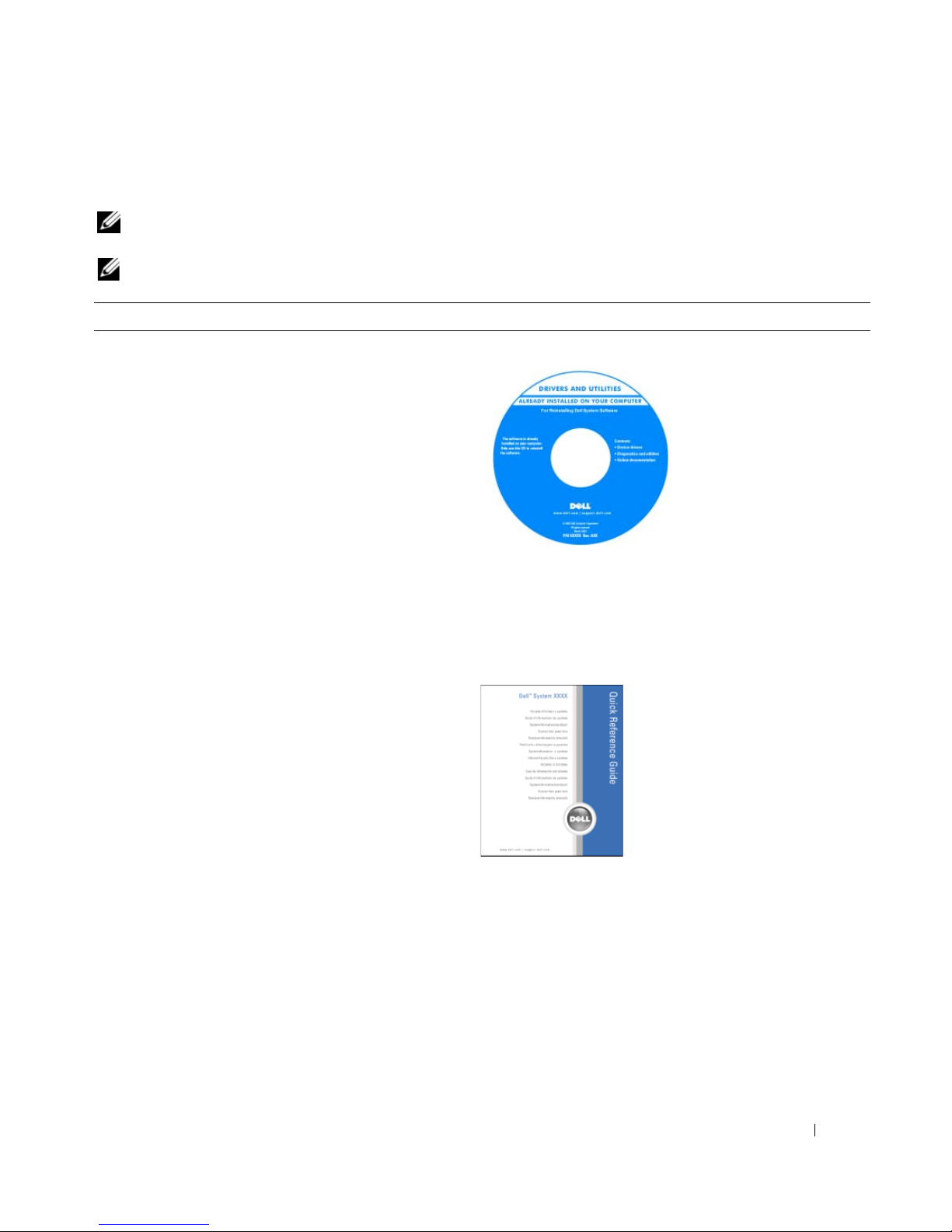
정보 찾기
주 : 일부 기능 또는 매체 베이는 선택 사양이므로 컴퓨터와 함께 제공되지 않을 수 있습니다 . 일부 기능 또
는 매체는 일부 국가에서 사용하지 못할 수 있습니다 .
주 : 추가 정보가 컴퓨터와 함께 제공될 수도 있습니다 .
찾는 정보 찾을 위치
•내
컴퓨터 진단 프로그램
•내
컴퓨터 드라이버
•내
컴퓨터 설명서
•내
장치 설명서
•
데스크탑 시스템 소프트웨어
(DSS)
Drivers and Utilities CD(Resource CD 라고도 함 )
설명서와 드라이버는 컴
퓨터에 이미 설치되어 있
습니다 . CD 를 사용하여
드라이버를 재설치하거
나 , Dell 진단 프로그램을
실행하거나 , 설명서에 액
세스할 수 있습니다 . CD
에 포함된 읽어보기 파일
에는 컴퓨터의 기술 변경
사항과 관련된 최신 업데
이트가 수록되어 있으며,
기술자와 숙련된 사용자를 대상으로 한 고급 기술 참조
자료입니다 .
주 : 드라이버 및 설명서 업데이트는 support.dell.com 에
서 찾을 수 있습니다 .
•내
컴퓨터 설치 방법
•내
컴퓨터 관리 방법
•
기본 문제 해결 정보
• Dell™
•
•
•내
진단 프로그램 실행 방법
오류 코드 및 진단 표시등
부품 분리 및 설치 방법
컴퓨터 덮개를 여는 방법
빠른 참조 안내서
주 : 이 설명서는 support.dell.com 에서 PDF 로 볼 수 있습
니다 .
빠른 참조 안내서 87
Page 88
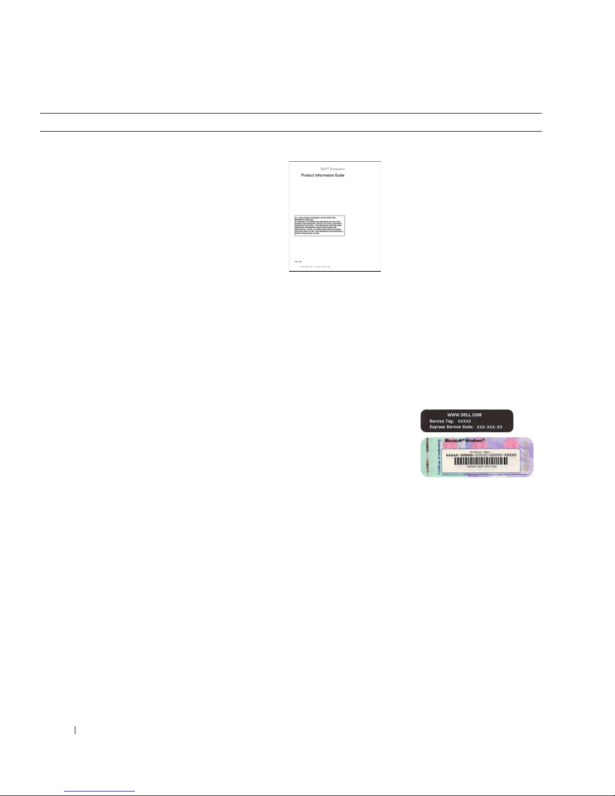
찾는 정보 찾을 위치
•
보증 정보
•
약관 및 조건(미국만 해당
•
안전 지침
•
규정사항
•
인체 공학 정보
•
최종 사용자 사용권 계약
•
부품 분리 및 교체 방법
•
사양
•
시스템 설정 구성 방법
•
문제 해결 방법
)
Dell™ 제품 정보 안내
사용 설명서
Microsoft
1
시작 단추를 클릭하고 도움말 및 지원을 클릭하십시오
2
사용 및 시스템 설명서를 클릭하고 사용 설명서를 클릭
하십시오
사용 설명서는 Drivers and Utilities CD 에도 있습니다 .
•
서비스 태그 및 특급 서비스 코드
• Microsoft Windows
라이센스 레이블
서비스 태그 및 Microsoft® Windows® 라이센스
이러한 레이블은 컴퓨터에 부착되어 있습니다 .
•
support.dell.com을
용하거나
문의할 때 서비스
에
태그를 사용하여 컴퓨
식별합니다
터를
기술 지원부에 문의할
•
때 특급 서비스 코드를
입력하여 전화 문의가 처리되도록 합니다
®
Windows® XP 도움말 및 지원 센터
.
사
기술 지원부
.
.
.
88 빠른 참조 안내서
Page 89

찾는 정보 찾을 위치
• Solutions —
기사 및 온라인 강좌
• Community —
•Upgrades —
문제 해결 참조 및 추가 정보, 기술 관련
, FAQ
다른
Dell
고객과 온라인 토론
메모리, 하드 드라이브, 운영 체제와 같은
구성요소 정보 업그레이드
• Customer Care —
,
보증, 수리 정보
태
• Service and support —
연락처, 기술 지원이 제공되는 온라인 토론
비스
• Reference —
,
부사항
제품 사양 및 백서
• Downloads —
연락처 정보, 서비스 콜 및 주문 상
서비스 콜 상태 및 지원 기록, 서
컴퓨터 설명서, 내 컴퓨터 구성에 대한 세
인증 드라이버, 패치, 소프트웨어 업데
이트
• Desktop System Software(DSS)—
재설치한 경우에 다른 드라이버를 설치하기 전에
를
유틸리티를 재설치해야 합니다
DSS
체제의 중요한 업데이트를 제공하고
영
USB
치
를
플로피 드라이브, 광학 드라이브 및
지원합니다
. DSS는 Dell
컴퓨터에 운영 체제
. DSS
에서는 운
Dell™ 3.5
USB
컴퓨터의 올바른 작동에
필수적입니다. 이 소프트웨어는 컴퓨터와 운영 체제
자동으로 감지하여 구성에 적합한 업데이트를 설
를
치합니다
.
Dell 지원 웹 사이트 — support.dell.com
주 : 해당 지원 사이트를 보려면 소재 지역이나 비지니스
세그먼트를 선택하십시오 .
주 : 기업 , 정부 및 교육 기관의 고객은
premier.support.dell.com 에서 사용자 정의된 Dell 프리미
어 지원 웹 사이트도 사용할 수 있습니다 . 이 웹 사이트는
일부 지역에서 사용할 수 없습니다 .
인
장치
• Windows XP
•
프로그램 및 파일을 사용하는 방법
•
장치 설명서(예: 모뎀
사용 방법
)
Windows 도움말 및 지원 센터
1
시작 단추를 클릭하고 도움말 및 지원을 클릭하십시오
2
문제를 설명해주는 단어나 문장을 입력한 다음, 화살표
아이콘을 클릭하십시오
3
문제를 설명해주는 항목을 클릭하십시오
4
화면의 지시사항을 따르십시오
.
.
.
.
빠른 참조 안내서 89
Page 90

찾는 정보 찾을 위치
•내
운영 체제 재설치 방법
운영 체제 CD
를 재설치하십시오 . 운영 체제 제품 키 레이블은 컴퓨터
에 부착되어 있습니다 .
주 : CD 의 색상은 주문한 운영 체제에 따라 다릅니다 .
주 : 운영 체제 CD 는 선택 사양이므로 컴퓨터와 함께 제
공되지 않을 수 있습니다 .
컴퓨터에는 이미 운영 체
제가 설치되어 있습니다 .
운영 체제를 재설치하려
면 운영 체제 CD 를 사용
하십시오 . 지시사항은 사
용 설명서를 참조하십시
오. 운영 체제를 재설치한
후 Drivers and Utilities
CD(ResourceCD) 를 사용
하여 컴퓨터와 함께 제공
된 장치에 맞는 드라이버
• Linux
• Dell Precision™
• Linux 및 Dell Precision
우편 토론
자
사용 방법
제품 및
Linux
운영 체제 사용자와 전
컴퓨터와 관련된 추가 정보
Dell 이 지원하는 Linux 사이트
• Linux.dell.com
• Lists.us.dell.com/mailman/listinfo/linux-precision
90 빠른 참조 안내서
Page 91
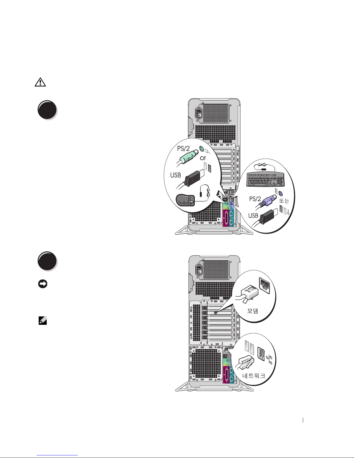
컴퓨터 설치
주의 : 이 항목의 절차를 수행하기 전에 제품 정보 안내에 있는 안전 지침을 따르십시오 .
컴퓨터를 제대로 설치하려면 모든 단계를 완료해야 합니다
1
키보드 및 마우스를 연결하십시오 .
.
2
모뎀 또는 네트워크 케이블을 연결하십
시오 .
주의사항 : 모뎀 케이블을 네트워크 어댑터에
연결하지 마십시오 . 전화 통신의 전압은 네트워
크 어댑터에 손상을 줄 수 있습니다 .
주 : 컴퓨터에 네트워크 카드가 설치된 경우 네트
워크 케이블을 카드에 연결하십시오 .
빠른 참조 안내서 91
Page 92
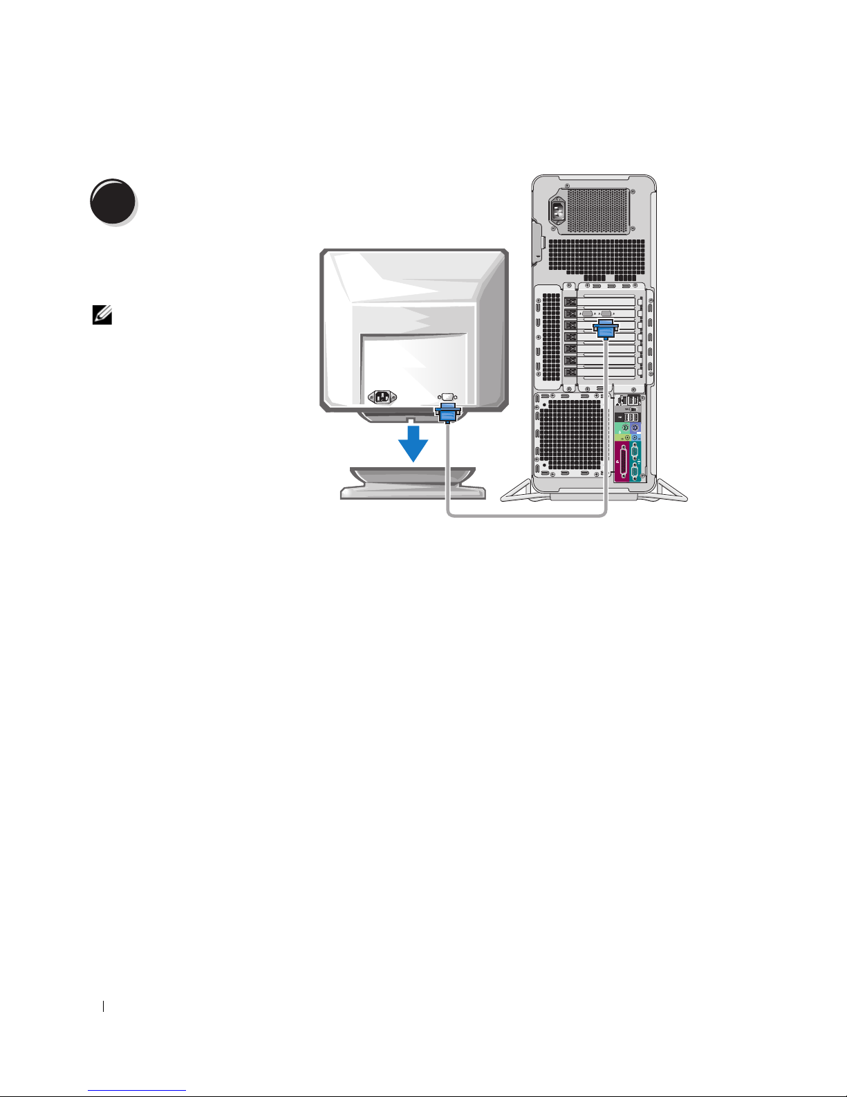
3
모니터를 연결하십
시오 .
그래픽 카드의 종류에 따라
다양한 방법으로 모니터를 연
수
결할
있습니다
주 : 모니터를 컴퓨터에 연
결하려면 제공된 어댑터
나 케이블을 사용해야 할
수 있습니다 .
.
92 빠른 참조 안내서
Page 93
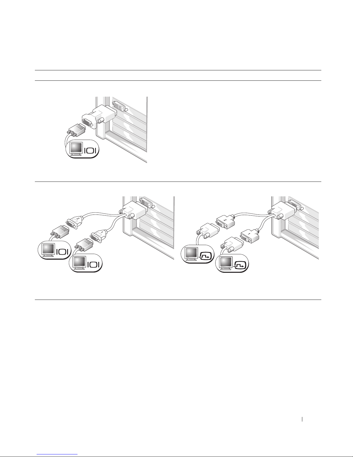
단일 커넥터가 있는 단일 및 듀얼 모니터가 가능한 카드의 경우
VGA 어댑터 1 개 :
VGA
단일 모니터 그래픽 카드가 있고 컴퓨터를 VGA 모니터
에 연결하려는 경우 VGA 어댑터를 사용하십시오 .
듀얼 VGA Y 케이블 어댑터 :
VGA
VGA
그래픽 카드에 단일 커넥터가 있고 컴퓨터를 1 개 또는
2 개의 VGA 모니터에 연결하려는 경우 해당 Y 케이블
을 사용하십시오 .
듀얼 DVI Y 케이블 어댑터 :
DVI
DVI
그래픽 카드에 단일 커넥터가 있고
2 개의 DVI 모니터에 연결하려는 경우 해당 Y 케이블을
사용하십시오 .
컴퓨터를 1 개 또는
듀얼 모니터 케이블은 색상 코드로 표시되어 있습니다. 청색 커넥터는 주 모니터용이고 검은색 커넥터
는
보조 모니터용입니다. 듀얼 모니터 지원을 활성화하려면 컴퓨터를 시작할 때 두 모니터가 모두 컴퓨
터에
연결되어 있어야 합니다
.
빠른 참조 안내서 93
Page 94
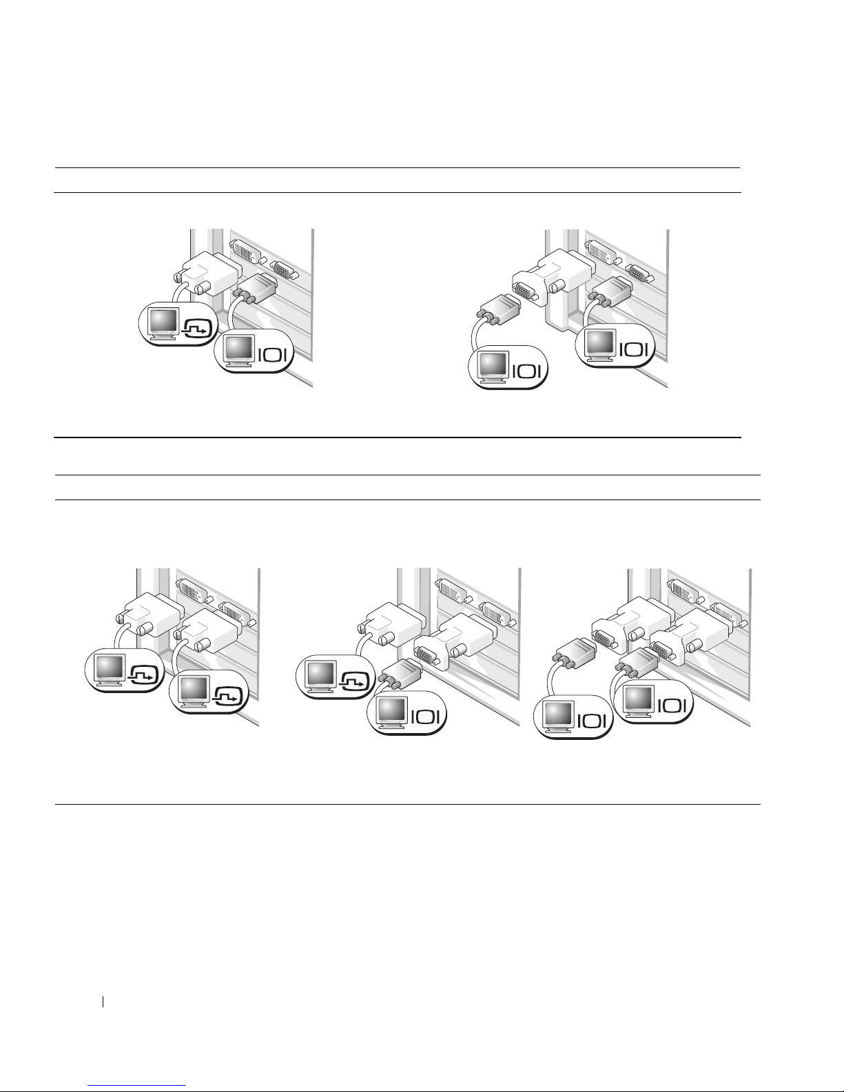
DVI 커넥터 1 개 및 VGA 커넥터 1 개가 있는 듀얼 모니터가 가능한 카드의 경우
DVI 커넥터 1 개 및 VGA 커넥터 1 개 :
DVI
VGA
컴퓨터를 1 개 또는 2 개의 모니터에 연결하려는 경우
해당 커넥터를 사용하십시오 .
DVI 커넥터 2 개가 있는 듀얼 모니터가 가능한 카드의 경우
DVI 커넥터 2 개 :
VGA 어댑터 1 개가 있는 DVI 커넥터
2 개 :
VGA 어댑터 1 개가 있는 VGA 커넥터 2 개 :
VGA
VGA
컴퓨터를 2 개의 VGA 모니터에 연결하려는 경우 VGA
어댑터를 사용하십시오 .
VGA 어댑터 2 개가 있는 DVI 커넥터
2 개 :
DVI
DVI
컴퓨터를 1 개 또는 2 개의 DVI 모니
터에 연결하려면 DVI 커넥터를 사용
하십시오 .
94 빠른 참조 안내서
DVI
VGA
VGA 모니터를 컴퓨터의 DVI 커넥터
중 하나에 연결하려면 VGA 어댑터를
사용하십시오 .
VGA
VGA
2 개의 VGA 모니터를 컴퓨터의 DVI
커넥터에 연결하려면 2 개의 VGA 어
댑터를 사용하십시오 .
Page 95
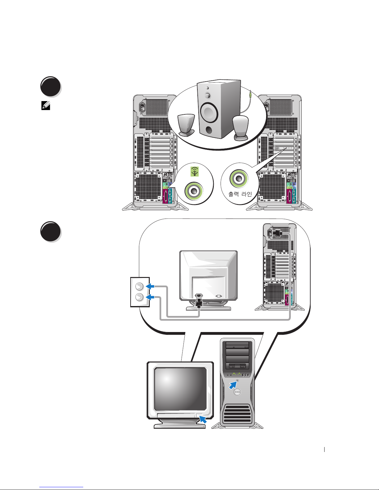
4
5
스피커를 연결하
십시오 .
주 : 컴퓨터에 사운드
카드가 설치된 경우
스피커를 카드에 연
결하십시오 .
전원 케이블을 연결
하고 컴퓨터 및 모니
터를 켜십시오 .
빠른 참조 안내서 95
Page 96
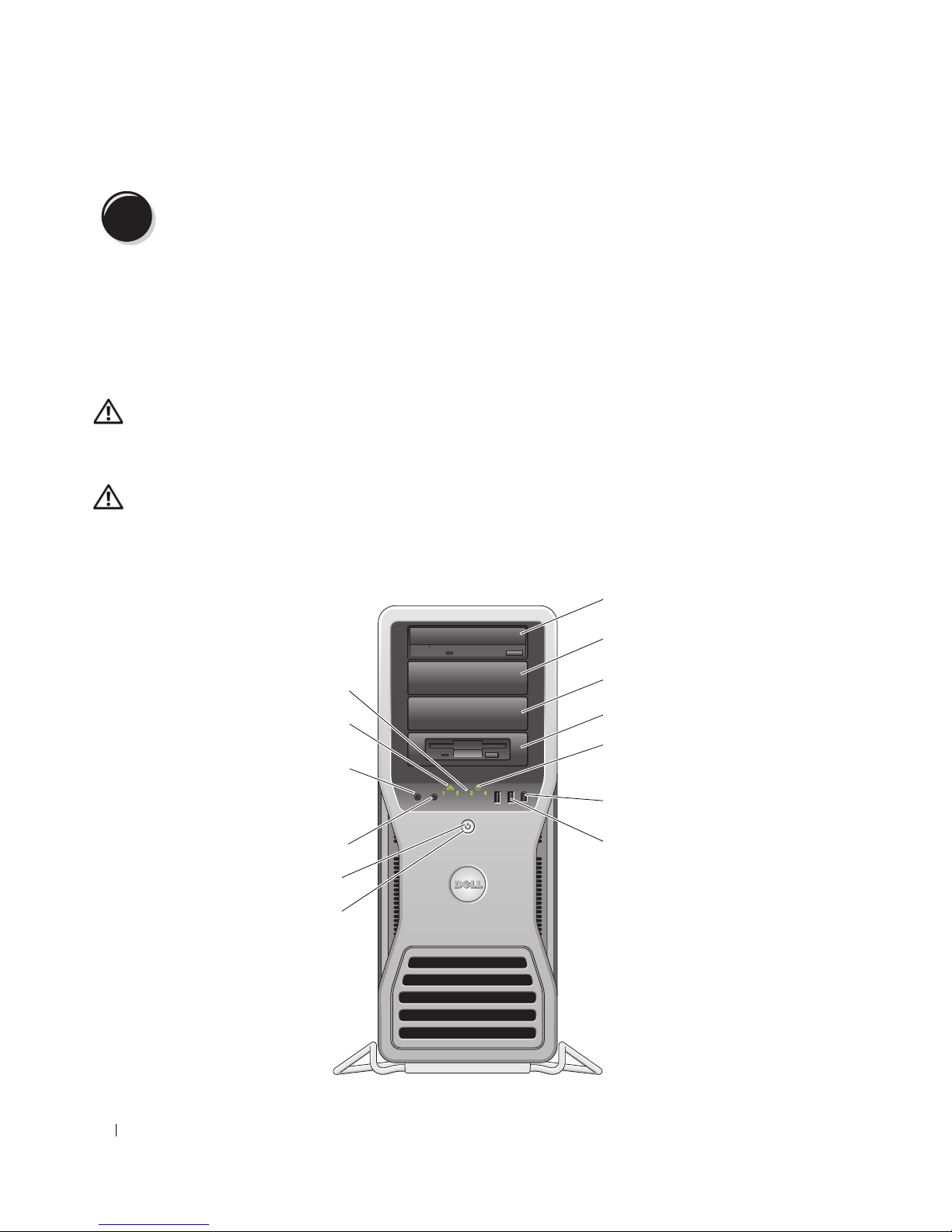
6
1
추가 소프트웨어 또는 장치를 설치하십시오 .
컴퓨터와 함께 제공되지 않은 모든 장치 또는 소프트웨어를 설치하기 전에 소프트웨어 또는 장치가 해
당
컴퓨터 및 운영 체제와 호환되는지 확인하려면 소프트웨어 또는 장치와 함께 제공된 설명서를 읽어
보거나
공급업체에 문의하십시오
.
컴퓨터 설치를 현재 완료했습니다
.
컴퓨터 정보
주의 : 컴퓨터가 무거워 ( 무게가 최소 55lb 정도 ) 다루기 어려울 수 있습니다 . 이 컴퓨터를 들거나 움직이
거나 기울이려면 도움을 받으십시오 . 이 컴퓨터를 들려면 두 사람이 필요합니다 . 부상을 방지하려면 컴퓨
터를 항상 올바르게 들어야 하며 들 때 몸을 위로 굽히지 마십시오 . 기타 중요한 안전 지침에 대한 내용은
제품 정보 안내를 참조하십시오 .
주의 : 컴퓨터를 똑바로 세우기 전에 컴퓨터 받침대를 설치하십시오 . 받침대를 설치하지 않고 컴퓨터를
똑바로 세우는 경우 컴퓨터가 뒤집혀질 수 있어 부상을 입거나 컴퓨터가 손상될 수 있습니다 .
전면 모습
2
13
12
11
3
4
5
96 빠른 참조 안내서
10
9
8
6
7
Page 97

1-3
5.25 인치 드라이브
베이
CD/DVD 드라이브 , Media Card Reader, 플로피 드라이브 또는 SATA 하드 드라
이브를 5.25 인치 드라이브 베이 캐리어에 수용할 수 있습니다 .
주 : 이러한 드라이브 캐리어는 5.25 인치 드라이브 베이에만 사용할 수 있습니
다 . 플로피 드라이브 /Media Card Reader 와 하드 드라이브 캐리어는 서로 바꿔
사용할 수 없습니다 .
4
특수 3.5 인치 드라이브
패널판이 있는 5.25 인
치 드라이브 베이
CD/DVD 드라이브 , Media Card Reader, 플로피 드라이브 또는 SATA 하드 드라
이브를 5.25 인치 드라이브 베이 캐리어에 수용할 수 있습니다 . 여기에 표시된
드라이브 패널판은 플로피 드라이브 또는 Media Card Reader와만
수 있으며 4 개 5.25 인치 드라이브 베이의 전면에 모두 설치될 수 있습니다 . 자
세한 내용은 사용 설명서를 참조하십시오 .
주 : 이러한 드라이브 캐리어는 5.25 인치 드라이브 베이에만 사용할 수 있습니
다 . 플로피 드라이브 /Media Card Reader 와 하드 드라이브 캐리어는 서로 바꿔
사용할 수 없습니다 .
5
하드 드라이브 작동 표
시등
6
IEEE 1394 커넥터 IEEE 1394 커넥터는 디지털
하드 드라이브 표시등은 컴퓨터가 하드 드라이브에서 데이타를 읽거나 저장할
때 켜집니다 . 이 표시등은 CD 플레이어와 같은 장치가 작동할 때도 켜질 수 있
습니다 .
이타 장치용으로 사용하십시오 .
함께 사용할
비디오 카메라 및 외부 저장 장치와 같은 고속 데
빠른 참조 안내서 97
Page 98
7
USB 2.0 커넥터 (2 개 ) 플래쉬 메모리 키 또는 카메라와 같이 가끔씩 연결하는 장치 또는 부팅 USB 장
치에 대해서는 전면 USB 커넥터를 사용하십시오 ( 자세한 내용은 사용 설명서
참조 ).
프린터 및 키보드와 같이 일반적으로 연결되어 있는 장치에는 후면 USB 커넥
터를 사용하는 것이 좋습니다 .
8
전원 단추 이 단추를 누르면 컴퓨터의 전원이 켜집니다 .
주의사항 : 데이타 손실을 방지하려면 컴퓨터의 전원을 끌 때 전원 단추
를 사용하지 마십시오 . 대신 운영 체제 종료를 수행하십시오 .
주 : 전원 단추는 시스템을 재개하거나 절전 상태로 전환할 때도 사용할 수 있습
니다 . 자세한 내용은 사용 설명서를 참조하십시오 .
9
전원 표시등 전원 표시등은 켜지고 깜박이거나 단색을 계속 유지하여 다음과 같이 여러 가
지 상태를 나타냅니다 .
•
표시등이 꺼져 있음
•
녹색으로 켜져 있음
•
녹색으로 깜박임
•
깜박이거나 호박색으로 켜져 있음 —사용 설명서의 "전원 문제"를 참조하십
.
시오
절전 상태를 벗어나려면 , 전원 단추를 누르거나 키보드나 마우스를 사용하십
시오 (Windows 장치 관리자에서 재개 장치로 설정된 경우 ). 슬립 상태 및 절전
상태에서 벗어나는 데 대한 자세한 내용은 사용 설명서를 참조하십시오 .
컴퓨터에 발생한 문제를 해결하는 데 도움을 주는 표시등 코드에 대한 설명은
115 페이지 " 진단 표시등 " 을 참조하십시오 .
10
마이크로폰 커넥터 마이크로폰 커넥터에는 사운드 또는
위한 PC 마이크로폰을 연결합니다 .
11
헤드폰 커넥터 헤드폰 커넥터에는 헤드폰을 연결하십시오 .
12
네트워크 연결 표시등 네트워크 연결 표시등은 10Mbps, 100Mbps 또는 1000Mbps( 또는 1Gbps) 네트
워크 및 컴퓨터 사이의 연결 상태가 좋을 때 켜집니다 .
13
진단 표시등 (4 개 ) 진단 코드를 기반으로 컴퓨터 문제를 해결하는 데 도움을 주는 이러한 표시등
을 사용하십시오 . 자세한 내용은 115 페이지
—
컴퓨터가 꺼져 있거나 최대 절전 모드에 있습니다
—
컴퓨터가 정상적으로 작동하고 있습니다
—
컴퓨터가 절전 상태에 있습니다
전화 프로그램에 음성 또는 음악 입력을
" 진단 표시등 " 을 참조하십시오 .
.
.
,
98 빠른 참조 안내서
Page 99
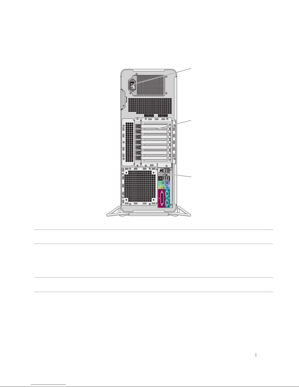
후면 모습
1
2
3
1
전원 커넥터 전원 케이블을 삽입하십시오 . 이 커넥터의 모양은 그림에서 표시된 것과 다를
2
카드 슬롯 설치된 모든 PCI, PCI-X 또는 PCI Express 카드용 커넥터에 액세스합니다 .
수 있습니다 .
주 : 5 개의 중심 커넥터 슬롯 (PCI 슬롯 1 개 , PCI express x16 슬롯 1 개 , PCI
express x8[x4 배선 ] 슬롯 1 개 , PCI-X 슬롯 2 개 ) 은 full-length 카드를 지원합니
다 . 상단 및 하단에 있는 커넥터 슬롯 (PCI express x8[x4 배선 ] 슬롯 2 개 ) 은
half-length 카드를 지원합니다 .
3
후면 패널 커넥터 직렬 , USB 및 기타 장치를
커넥터 " 참조 ).
해당 커넥터
에 꽂으십시오 (100 페이지 " 후면 패널
빠른 참조 안내서 99
Page 100
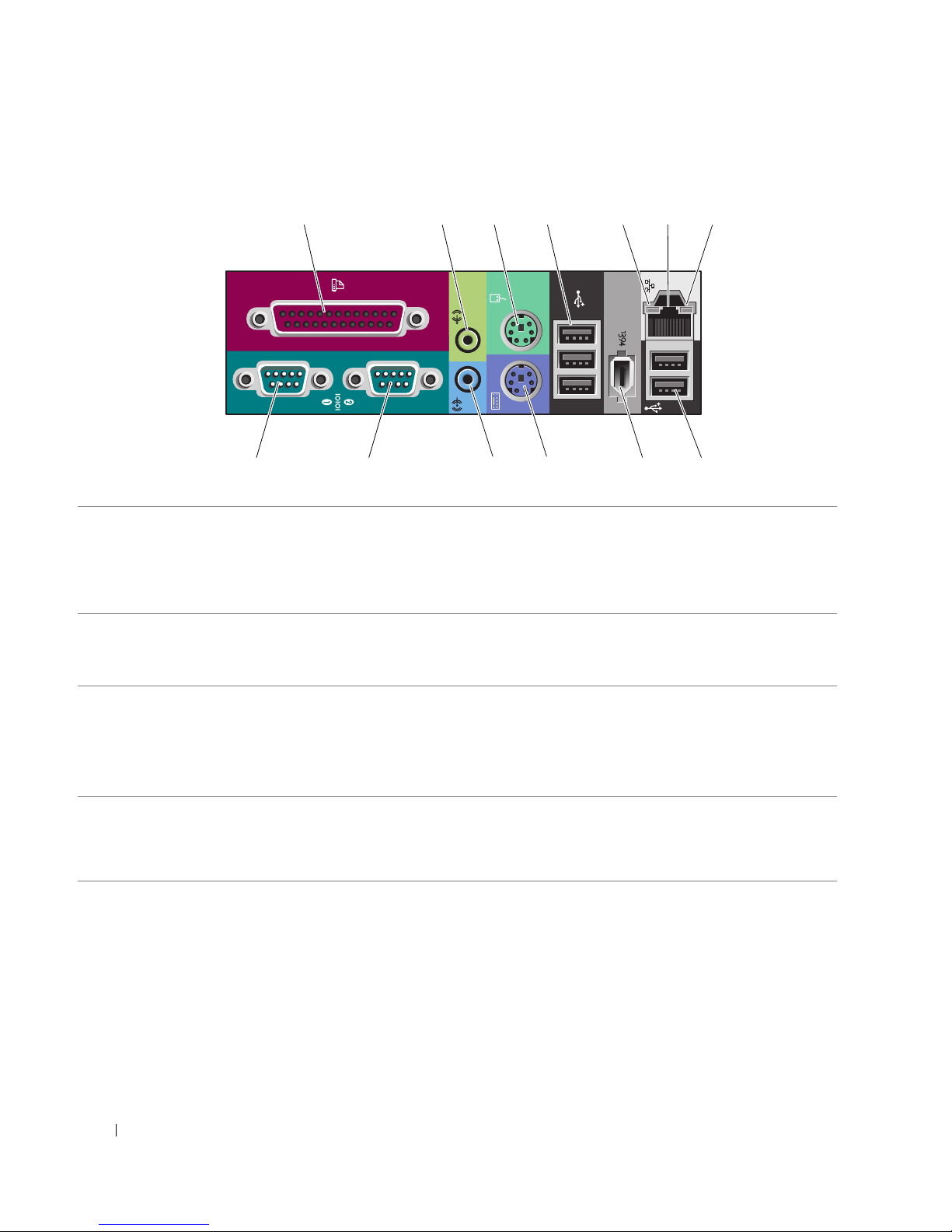
후면 패널 커넥터
1 234 6
57
13 12 11 10 89
1
병렬 커넥터 프린터와 같은 병렬 장치를 병렬 커넥터에 연결하십시오 . USB 프린터를 사용
하는 경우에는 USB 커넥터에 연결하십시오 .
주 : 컴퓨터가 동일한 주소에 구성된 병렬 커넥터가 들어 있는 설치된 카드를 감
지하면 내장형 병렬 커넥터는 자동으로 비활성화됩니다 . 자세한 내용은 사용
설명서를 참조하십시오 .
2
출력 라인 / 헤드폰 커넥터녹색 출력 라인 커넥터에는 대부분의 내장형 증폭기가 달린 스피커 및 헤드폰
을 연결합니다 .
사운드 카드가 있는 컴퓨터에서는 카드의 커넥터를 사용하십시오 .
3
마우스 커넥터 녹색 마우스 커넥터에
하기 전에 컴퓨터 및 모든 연결 장치를 끄십시오 . USB 마우스를 사용하는 경우
에는 USB 커넥터에 연결하십시오 .
®
Microsoft
스 드라이버는 하드 드라이브에 설치되어 있습니다 .
4
USB 2.0 커넥터 (3 개 ) 플래쉬 키 , 카메라와 같이 가끔씩 연결하는 장치 또는 부팅 USB 장치에 대해서
는 전면 USB 커넥터를 사용하는 것이 좋습니다 .
프린터 및 키보드와 같이 일반적으로 연결되어 있는 장치에 대해서는 후면
USB 커넥터를 사용하십시오 .
Windows® XP 운영 체제를 사용하는 컴퓨터인 경우 , 필요한 마우
표준 마우스를 연결하십시오 . 마우스를 컴퓨터에 연결
100 빠른 참조 안내서
 Loading...