

Page 1

Troubleshooting the
Dell PowerVault MD-Series
Storage Array
Configuring the Ethernet Management Port
Page 2

THIS WHITE PAPER IS FOR INFORMATIONAL PURPOSES ONLY, AND MAY CONTAIN TYPOGRAPHICAL ERRORS AND TECHNICAL
INACCURACIES. THE CONTENT IS PROVIDED AS IS, WITHOUT EXPRESS OR IMPLIED WARRANTIES OF ANY KIND.
© 2012 Dell Inc. All rights reserved. Reproduction of this material in any manner whatsoever without the express written
permission of Dell Inc. is strictly forbidden. For more information, contact Dell.
l, the DELL logo, and the DELL badge, PowerVault are trademarks of Dell Inc. Other trademarks and trade names may be used
Del
in this document to refer to either the entities claiming the marks and names or their products. Dell Inc. disclaims any proprietary
interest in trademarks and trade names other than its own.
June 2012
Page 3

Contents
About this Document ..................................................................................................... 4
Managing the MD-Series Storage Array ................................................................................ 5
Out-of-Band Management vs. In-Band Management.............................................................. 5
Setting Up Management Using MD Storage Manager ............................................................. 5
Troubleshooting the Ethernet Management Port .................................................................... 8
Locating the Managem ent Po rt ...................................................................................... 8
Default Port IP Addresses ............................................................................................. 8
Recognizing Issues Involving the Ethernet Management Port ................................................... 9
Basics: Cabling, Power and Network Switches .................................................................... 9
Troubleshooting Physical Connectivity Problems ............................................................... 11
Troubleshooting Management Port IP Addressing and Configuration ....................................... 12
Using a Serial Cable to Configure Your Management Port .................................................... 15
Troubleshooting Management Port Device Discovery Issues .................................................. 16
Page 4

About this Document
To understand the scope and organization of this document, refer to the following table.
Topic Description
What does this document
contain?
What is the intended
audience?
How is information
categorized?
For more information See the following:
An overview of the management features of the
PowerVault MD-series storage arrays
Recommended recommended out-of-band management
configuration and setup
Potential errors that that may occur if the Ethernet
management port is incorrectly configured, including
steps on how to resolve
Other troubleshooting information relating to the MD-
series iSCSI storage arrays
Users experiencing problems setting up out-of-band
management of the MD storage array or experiencing
problems with the Ethernet management port of the
storage array
This document is divided into three broad sections:
Understanding physical connectivity between the
Ethernet management port and management station
Recognizing and correcting management port IP address
problems
Recognizing and correcting device discovery erro rs
MD-series user documentation at
support.dell.com/manuals
MD-series video series at
del.ly/PowerVaultMD
Page 5

Managing the MD-Series Storage Array
One of the most critical issues in establishing an efficient storage management architecture is placing
data traffic and management traffic on the proper networks. When setting up management on any Dell
PowerVault MD-Series storage array, Dell recommends that you always separate management traffic
from the server-to-storage array data path using different subnetworks, or subnets.
This management method is commonly called out-of-band management.
Out-of-Band Management vs. In-Band Management
Out-of-band management prevents traffic on the Ethernet management ports of your storage array
from interfering with critical data I/O between the storage array and server. While in-band
management − routing management traffic and data I/O on the same data path − is supported on the
MD storage array, it will likely result in an across-the-board reduction in performance and/or
throughout.
Setting Up Management Using MD Storage Manager
Dell PowerVault MD Storage Manager is a graphically based tool that allows you to fully manage,
configure and provision your MD-series storage arrays.
To set up your Ethernet management port in MD Storage Manager:
Launch MD Storage Manager
From the Setup tab, choose Configure Ethernet Management Ports
Using the Change Network Configuration wizard, enter the port and IP address information for the
management port on both RAID controller modules.
Page 6
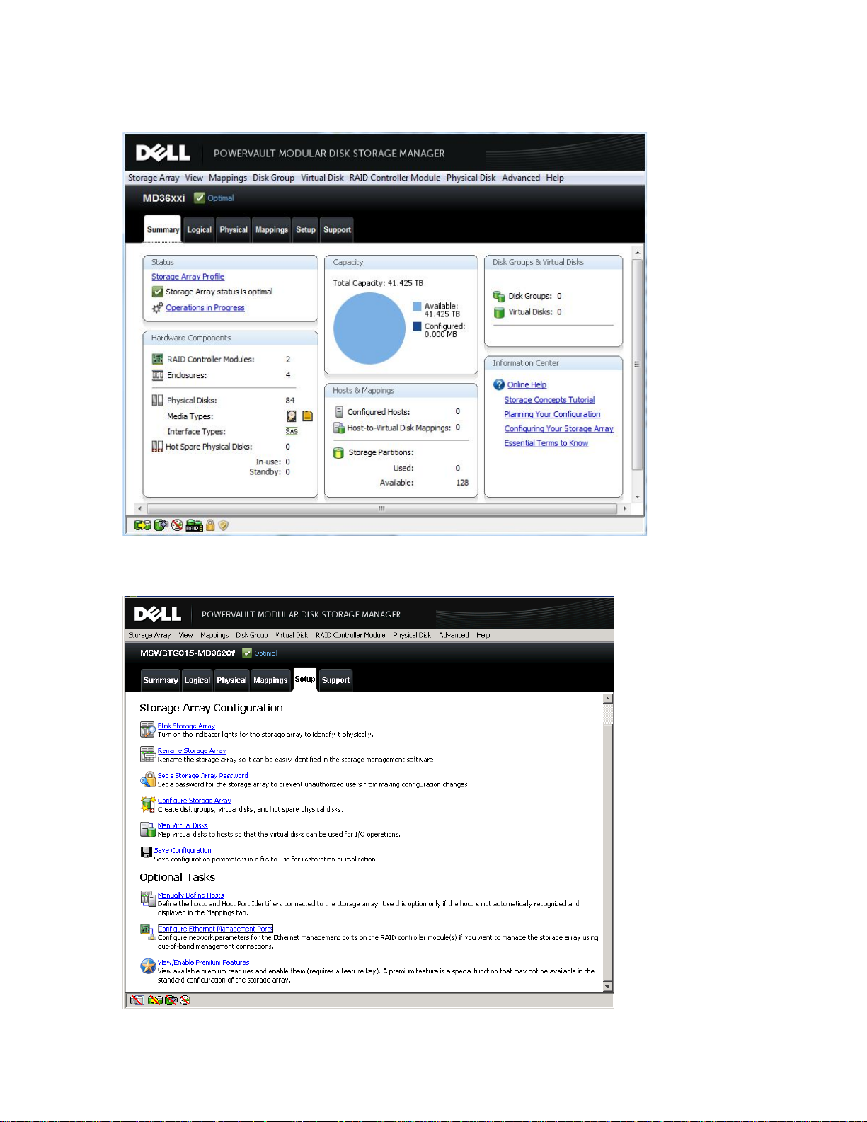
Figure 1. MD Storage Manager Summary View
Figure 2. MD Storage Manager Setup View
Page 7

Figure 3. MD Storage Manager Configure Management Ports
NOTE: IPv4 and IPv6 are both supported protocols on the MD-series iSCSI storage arrays. Whichever
one you use, be aware of the following:
It is possible to enable both IPv6 and IPv4 on your host server. However, Dell
recommends that you disable the one you are not using before setting up your storage
array. Having both enabled may cause miscommunication between the storage array and
host server.
Make sure that the protocol you choose is enabled on both the storage array and host
server. Mixing protocols (for example, enabling IPv4 on the storage array and IPv6 on the
host server) will cause session interrupts and possible loss of data.
Once the storage array is successfully added to MD Storage Manager, all physical and logical
components of your storage array are manageable using the menu-based interface. For more
information on installing and using MD Storage Manager, see the Getting Started Guide and
Deployment Guide that shipped with your storage array. The Help option from the MD Storage
Manager main window also offer additional guidance.
Page 8

Troubleshooting the Ethernet Management Port
The Ethernet management ports on the MD-series RAID controllers allow you to manage your storage
array via a separate management network from the host server data path (known as out-of-band
management).
Dell recommends always using out-of-band management to manage your storage array.
Locating the Management Port
Each RAID controll er module contains a 100/1000 Mbps Ethernet management port. Whether you are
using SAS, iSCSI or Fibre Channel, the management port is located in same same position.
Figure 4 shows the management ports on an MD3600i-series iSCSI storage array.
Figure 4. Management Ports on an MD3600i-series storage array
Default Port IP Addresses
Each port on the storage array is assigned a default, factory-set IP address. Since DHCP is enabled by
default for the management ports at the factory (however, not for the host server ports), these
addresses should be discoverable when the storage array is initially powered on.
Table 1. Default IP Addresses on M D-series storage array (all models)
Controller 0 Controller 1 Subnet mask
Port ID
iSCSI port 0
iSCSI port 1
iSCSI port 2 *
iSCSI port 3 *
Ethernet
management port
* Port 2 and 3 are available on 1Gb iSCSI MD3200i-series storage arrays only
192.168.130.101 192.168.130.102 255.255.255.0
192.168.131.101 192.168.131.102 255.255.255.0
192.168.132.101 192.168.132.102 255.255.255.0
192.168.133.101 192.168.133.102 255.255.255.0
192.168.128.101 192.168.128.102 255.255.255.0
Page 9

Recognizing Issues Involving the Ethernet Management Port
Problems occurring due to misconfigured or nonfunctional Ethernet management ports on your storage
array's RAID controller modules can appear in a number of different ways. However, typical
management port issues may include:
− Status LEDs on iSCSI ports not lit or indicating fault (refer to Table 2 for LED values)
− Unable to ping an iSCSI port from the host server on the same subnet
− Dynamic Host Configuration Protocol (DHCP) is unable to assign an IP address for one or more
of your RAID controller modules
− Duplicate IP addresses appear (either manually set or multiple arrays with the same factory
default IP addresses)
Basics: Cabling, Power and Network Switches
Simple issues, such as an improperly seated Ethernet cable or a defective and/or powered-down
hardware component, are often the root cause of a number of problems. If a physical link error occurs
or you are unable to connect to a storage array in MD Storage Manager, it is always useful to perform a
simple, standard troubleshooting protocol:
1. Verify you have a solid, well-seated connection between the RAID controller module's Ethernet
management port(s) and your host server and/or network switch.
2. If you are using a network switch, verify the following:
- All active link and link status LEDs are lit (an unlit activity LED is not necessarily a
problem)
- The Ethernet switch you are using is compatible with your RAID controller module (for
example, is compatible with 1Gb MD3200i-series and/or 10Gb MD3600i-series arrays)
Do not connect an Ethernet switch with a speed of less than 1Gb to the storage array
-
3. Verify that MD-series storage array enclosures and RAID controller modules are powered on and
show the proper LED status configurations. (See Table 2.) For additional MD-specific LED
diagnostic information, see support.dell.com/manuals.
4. Ensure that all cabling and connectors are functional. If uncertain, swap current cables with
known good cables to determine if the problem is related.
Page 10

Figure 5. Enclosure Status LE D s (Front)
LED
Function
Enclosure status
Solid blue: Normal operation
preferred path to virtual disks
Enclosure power
Solid green: At least one power supply active
Table 2. Enclosure Status LED Values
Blinking blue: Host identifying
Solid amber: Enclosure rebooting or being reset
Blinking amber: Enclosure fault or host not using
Figure 6. Enclosure/RAID Controller Module Status LEDs (Back)
Page 11

Table 3. Enclosure/RAID Controller Status LED Values
LED
Function
DC Power
Solid green: DC output voltage within limit
Off: DC output voltage not within limit
Power supply/fan fault
Solid amber: DC output voltage not within limit or fan fault
Off: No fault condition
AC power
Solid green: AC input voltage within limit
Off: No power or AC input voltage is not within limit
Controller power
Solid green: Controller powered on
Off: Controller powered off
Controller fault
Solid amber: Controller fault detected
Off: Controller operating normally
iSCSI port link
Solid green: 10Gbps Ethernet connection established
Off: No link
iSCSI port activity
Solid green: No activity/connection.
Off: No link
Management port speed
Solid green: 1Gbps Ethernet connection established
Management port activity
Solid green: Port active/connection
Issue/Problem
Recommendation
Suspected bad
Replace the suspected bad cable with a known good
cable. If problems persist, cable is probably OK.
Solid amber: 1Gbps Ethernet connection established
Blinking green: Port active, connection
detected
Blinking amber: 100Mbps Ethernet connection established
Off: No link or 10Mbps connection established
Off: No activity
Troubleshooting Physical Connectivity Problems
When experiencing problems with the Ethernet management ports, always check first for simple
connectivity issues (see Basic Cabling, Power and Switch Issues). If problems persist, refer to the
following table:
Table 4. Diagnosing Management Port Connectivity
Ethernet cable
Page 12

No link LEDs vi
sible on RAID
controller (rear)
If you are using a network switch, verify
powered on and Ethernet ports on both the network
switch and RAID controll er are act iv e. Also, ma ke
sure the storage
Reduced throughput
If you have connectivity but are experiencing
reduced throughout, make sure your iSCSI port is not
connecting to the host server through a slower
expected speed. For example, a 10Gb port can
connect using a 1Gb network switch, but the slower
switch wi
Issue/Problem
Recommendation
What is the IP address
of the Ethernet
management port?
The management port appears differently
servers:
that it is
array enclosure is powered on.
-than-
ll impact throughput.
Troubleshooting Management Port IP Addressing and Configuration
If problems persist, refer to the following table:
Table 5. Diagnosing Managemen t P or t C onfiguration Problems
DHCP server
(IPv4)
non-DHCP server
(IPv4)
All IPv6-enabled
configurations
to DHCP and non-DHCP
On a network running DHCP server, IP
addresses for the Ethernet manag em e nt port s
are assigned automatically
On a non-DHCP netwo rk server, the Ethernet
management ports will def a ult to the following
IP addresses following a three-minute timeout
(from initial polling or connection attempt):
Controller 0:
192.168.128.101
Controller 1:
192.168.128.102
Subnet mask:
255.255.255.0
Each management port has a default link local
IP address that is based on the MAC address of
the port (unless IPv6 is specifically disabled on
a port).
Page 13

Duplicate
or multiple
management
addresses
appearing
host server
If DHCP
network will default to the same management IP address
address duplication errors. To fix this problem, add each storage array
to the network
value
M
settings
Always use auto
management
on the RAID controller
Ports
drop
M
showing as
Disconnected
Use the ping command to contact the Ethernet management port.
Unless the ping command originates from a
separate, non
is
connected or
Non
addresses are
overriding
addresses
If you
previously
addresses.
ports.
How do I access
management ports on
an
network?
The Ethernet management ports on the
accessible using the IPv6 link local address
address of the
Default IP addresses
not auto
If
configure
starts
Ethernet
Can I use m
network i
(NICs) on same subnet
Dell recommends that you
host on the same subnet
IP address confusion, especially
It is
always preferable to isolate management data traffic from storage
array
ad
easier to manage and troubleshoot.
Having p
VLAN
The Ethernet management ports on the MD
not
network
port
port IP
are
(non-DHCP
)
is not enabled, multiple storage arrays connecting to a
, causing IP
individually and change its IP addresses to non-default
s before adding another storage array.
anagement port speed
are incorrect
anagement port
-default IP
default IP
IPv6-enabled
-negotiation when configuring the Ethernet
ports. In MD Storage Manager Physical pane, right click
module and select Configure > Management
and choose Auto-negotiate from the S peed and duplex mode
-down menu.
management station on a
-networked switch, it should indicate whether the port
disconnected.
are using DHCP and have configured static IP addresses
, those static IP addresses will override the default
To fix this issue, manually reconfigure the management
MD storage array are also
es determined by the MAC
port (unless it is has been disabled).
the DHCP server does not respond, default IP addresses will auto-
-configuring
ultiple host
nterface cards
?
dition to avoiding performance slowdowns, this configuration is
roblems with
following a three-minute timeout. This timeout interval
either when the RAID controller module boots up or a new
management port connection is established.
-to-host server traffic on separate subnets and multiple NICs. In
support VLAN tagging. Make sure that tagging is disabled on the
switch for any port connected to the Ethernet management
(s).
do not configure more than one NIC per
. Multiple NICs on the same subnet can cause
in direct-attached configurations.
-series storage arrays do
Page 14

How do I know if
Ethernet management
ports correctly
configured
?
To verify that your management ports are functional, use the p
command
addresses of
successful
However, you cannot verify you are able to manage the storage array
until you have an array
I c
problem
If you are still unable to
addresses
Configure
my
ing
from your management station to connect to the IP
each Ethernet management port on the storage array. A
ping means the ports are configured and ready to use.
annot diagnose my
properly configured and running.
configure the Ethernet management port IP
on your MD storage array, see Using a Serial Cable to
Your Management Port.
Page 15

Using a Serial Cable to Configure Your Management Port
When other troubleshooting steps fail, using a serial cable to connect to your Ethernet management
port is an option. Perform the following steps on any management station with a serial port available.
A serial debug cable is available from your Dell support representative.
1. Connect the PS/2 connecter on the serial debug cable to the serial debug port on RAID
controller. (See Figure 3 for serial port location.)
2. Connect the DB-9 connector on the serial debug cable to your management station.
3. Open any serial shell utility (PuTTY, Tera Term, HyperTerminal or Minicom (Linux)).
4. In your serial shell utility, set the baud rate to 115200.
NOTE: The default baud rate for the MD storage array is 115200. If you do n ot see a respon se at 115200,
enter a break command repeatedly until legible text appears. Press the spacebar to set the baud rate to
the speed which allows legible text to display.
Other shell utility connection settings for the MD storage array are typica l :
Data bits: 8
Parity: none
Stop bits: 1
Flow control: none
5. Once you set the baud rate and verified default settings, enter another break command.
6. When the options are displayed, type an uppercase S.
7. At the password prompt, enter supportDell
8. Select from the menu options shown to view or modify the port settings:
- Option 1 to view the current management port configuration
- Option 2 to modify the current management port configuration
Enter a period (.) to make no changes and return to default settings
9. When finished, type Ctrl+D to save your changes and exi t.
Page 16

Troubleshooting Management Port Device Discovery Issues
command. Check the LEDs on the RAID controller
If your Ethernet management ports are properly configured but you are having problems discovering
storage arrays or RAID controller modules, refer to the following table below.
NOTE: Many device discovery problems are similar to those det ailed in Tabl e 1 for the Ethernet management port,
although they occur during the discov ery p roc ess.
Table 6. Diagnosing Device Discovery Problems
Issue/Problem Recommendation
Firewall is blocking discovery of
management port
RAID controller modules are not
running
Ensure that TCP and UDP ports 2463 are open on
your firewall. MD Storage Manager uses both ports
for discovery and management. Verify that the
firewall settings in your local environment do not
block your ports.
A RAID controller module cannot be added to the
management view in MDSM until it has successfully
completed its boot process.
To verify that a RAID controller module has
successfully booted, perform one of the following:
• Check the Enclosure Status LED at the
front of the storage array. (See Table 2, LED
Enclosure Status Values.)
• Using the procedure described in Using a
Serial Cable to Configure Your Management
Port, connect to the serial port of the MD
storage array and observe your RAID
controller boot sequence. If
SODMainComplete is displayed, the RAID
controller has successfully booted and should
be visible to MDSM.
RAID controller module in
Lockdown mode
RAID controller module is in
Offline mode
If a RAID controller module detects certain error
conditions, it enters a Lockdown mode. While in
this mode, the Ethernet management ports will
respond to
session cannot be established. Check the
Controller Fault LED or System Identification ID
LED on the RAID controller. If either LED is solidly
lit (Controller Fault LED is amber or System
Identification ID LED is blue), contact your Dell
technical support representative.
Similar to a Lockdown state, a RAID controller
module may also go into Offline status. However,
while in an Offline status, the Ether net
management port will not respond to a
ping commands but a full management
ping
Page 17

module to determine whether a fault condition is
indicated.
module
to add a RAID controller module to an already
Automatic Discovery fails on an
IPv4 subnetwork
Do I need to configure both
management ports on dualcontroller (duplex) storage array?
Automatic discovery of storage arrays is not
supported on IPv4-enabled subnets. Verify the
following:
- you can successfully ping the management
ports on the storage array
- the management ports are on separate
subnets than your management station
If both are true, manually add the storage array(s)
to MD Storage Manager (see Manually Adding a
Storage Array to MD Storage Manager).
A dual-controller storage array is considered
partially managed if only one of the two available
Ethernet management ports are configured. Many
management commands require access to both the
owning and non-owning RAID controller module -for example, IP configuration or virtual disk
creation. To fix this issue, repeat discovery
(automatic or manual) and configure the second
management port.
NOTES:
- Partially managed storage arrays can have
alternate paths added through both autodiscovery and manual configuration. See
Manually Adding a Storage Array to the
Management Software View.
- If you are able to ping a RAID controller module
but not perform management operations, it
may be in Lockdown state. See RAID controller
in Lockdown mode.
Management operations requiring
access to the owning RAID
controller fail
Management port showing as
Disconnected
Manually adding a RAID controller
see previous issue
A management port may show as Disconnected for
a number of reason. Common causes are:
automatic discovery failed because your
management station is connected to a nonnetworked switch with a single data path the
storage array
only one management port is configured
faulty cable/physical connection
In cases of replacement or upgrade, you may need
Page 18

existing management view in MD Storage Manager.
Perform these steps:
1. Obtain the IP address of the RAID controller
you are adding. If the IP address is unknown,
see Using a Serial Cable to Configure Your
Management Port.
2. Start MD Storage Manager and select the MD
storage array containing the RAID controller.
3. From the Setup tab in the Array
Management Window, select Add Storage
Arrays.
4. In the Select Addition Method, select
Manual.
5. In the Add New Storage Array window,
select Out-of-Band manag ement and enter
the IP address of the RAID controller.
6. Click Add.
If you are adding a single RAID controller
module or a new path to a management
port, a confirmation message appears.
7. Select Yes.
The new path and the existing path are
automatically merged.
 Loading...