

Dell PowerVault MD3200i Series, PowerVault MD3220i Series Technical Manualbook

DELL PowerVault MD3200i/MD3220i
Series of Storage Arrays
A Dell Technical Guide Book
Version 1.0

DELL PowerVault MD3200i/MD3220i Technical Guide Book
THIS WHITE PAPER IS FOR INFORMATIONAL PURPOSES ONLY, AND MAY CONTAIN TYPOGRAPHICAL
ERRORS AND TECHNICAL INACCURACIES. THE CONTENT IS PROVIDED AS IS, WITHOUT EXPRESS OR
IMPLIED WARRANTIES OF ANY KIND.
© 2010 Dell Inc. All rights reserved. Reproduction of this material in any manner whatsoever without
the express written permission of Dell Inc. is strictly forbidden. For more information, contact Dell.
Dell, the DELL logo, and the DELL badge, PowerConnect, and PowerVault are trademarks of Dell Inc.
Microsoft, Windows, and Windows Server are either trademarks or registered trademarks of Microsoft
Corporation in the United States and/or other countries. Other trademarks and trade names may be
used in this document to refer to either the entities claiming the marks and names or their products.
Dell Inc. disclaims any proprietary interest in trademarks and trade names other than its own.
June 2010
ii

DELL PowerVault MD3200i/MD3220i Technical Guide Book
Contents
1. Product Overview ...................................................................................................... 3
2.1 iSCSI ..................................................................................................................... 3
2.2 6Gb Serial Attached SCSI (SAS 2.0) ................................................................................ 4
3. Controller Architecture ............................................................................................... 5
3.1 MD3200i RAID Controller Module View - LEDs.................................................................... 6
4. Chassis ................................................................................................................... 8
4.1 Dimensions and Weight .............................................................................................. 8
4.2 Front View and Features ............................................................................................ 9
4.3 MD3200i and MD3220i Rear View ................................................................................. 12
4.4 Power Supply Indicator Codes .................................................................................... 13
5 Hard Drives ............................................................................................................. 14
5.1 Hard Drive Indicators .............................................................................................. 15
6. Storage Capacity Expansion ........................................................................................ 16
7. SAS Cables ............................................................................................................. 17
8. MD Storage Manager ................................................................................................. 18
8.1 MD3200i Series Storage Manager Software Packages ......................................................... 19
8.2 Enterprise Window ................................................................................................. 19
8.3 Array Window ....................................................................................................... 20
8.4 Recovery Guru ....................................................................................................... 27
9. Working with Physical and Logical Disks ......................................................................... 28
9.1 Disk Group Configuration .......................................................................................... 28
9.2 Virtual Disk Configuration ......................................................................................... 29
9.3 Configuration Metadata ........................................................................................... 29
9.4 Global Hot Spares ................................................................................................... 30
9.5 Storage Partitioning ................................................................................................ 30
9.6 Snapshot .............................................................................................................. 31
9.7 Virtual Disk Copy .................................................................................................... 31
9.8 Online Administration .............................................................................................. 32
9.9 iSCSI Support ........................................................................................................ 33
9.10 Host Operating System Support ................................................................................. 33
10 Environmental ........................................................................................................ 33
10.1 Power Supply Specs ............................................................................................... 33
10.2 Thermal management ............................................................................................ 34
10.3 Over-Temperature Shutdown ................................................................................... 34
1

DELL PowerVault MD3200i/MD3220i Technical Guide Book
10.4 Environmental Specifications ................................................................................... 35
11. Configuration Guidelines .......................................................................................... 36
11.1 General Configuration Rules .................................................................................... 36
Tables
Table 1. Selected Controller Features: ............................................................................. 7
Table 2. Detailed Dimensions (mm) ................................................................................. 8
Table 3. MD3200i and MD3220i Front Panel Feature Description ............................................ 11
Table 4. Supported Drives ........................................................................................... 14
Table 5. Supported RAID Configurations .......................................................................... 29
Table 6. Power Supply Specifications ............................................................................. 34
Table 7. Environmental Specifications ............................................................................ 35
Figures
Figure 1. RAID controller architecture of the MD3200i controller. ............................................. 5
Figure 2. MD3200i RAID Controller Module View - LEDs............................................................ 6
Figure 3. MD3200i and MD3220i Dimensions ......................................................................... 8
Figure 4. MD3200i Front View and Features ......................................................................... 9
Figure 5. MD3200i Front Panel Indicators ............................................................................ 9
Figure 6. MD3220i Front View and Features ....................................................................... 10
Figure 7. MD3200i Front Panel Indicators .......................................................................... 12
Figure 8. MD3200i and MD3220i Front Bezel Feature and Indicators .......................................... 12
Figure 9. MD3200i and MD3220i Rear View ......................................................................... 12
Figure 10. Power Supply Indicator Codes ........................................................................... 12
Figure 11.
Figure 12. Expansion and cabling .................................................................................... 16
Figure 13. Mini-SAS Cable Transition ................................................................................ 17
Figure 14. MD Storage Manager: Enterprise Window ............................................................. 19
Figure 15. MD Storage Manager: Setup Tab ........................................................................ 20
Figure 16. MD Storage Manager: Array Window.................................................................... 21
Figure 17. MD Storage Manager: Logical Tab ....................................................................... 22
Figure 18. MD Storage Manager: Physical Tab ..................................................................... 23
Figure 19. MD Storage Manager: Mappings Tab .................................................................... 24
Figure 20. MD Storage Manager: Setup Tab ........................................................................ 25
Figure 21. MD Storage Manager: Access to Tasks .................................................................. 26
Hard Drive Indicators (includes HDD and SSD) ........................................................ 15
Figure 22. MD Storage Manager: Support Tab ...................................................................... 27
2

DELL PowerVault MD3200i/MD3220i Technical Guide Book
Product Overview
The MD3200i series of storage arrays were designed with performance in mind. Each controller is
equipped with four 1Gb Ethernet ports providing total aggregated bandwidth of 800MB/s of throughput
for a dual controller system which is double the throughput of the MD3000i and most competitive
products in the entry-level iSCSI SAN array market. For small block random access applications like
databases, the MD3200i series is capable of performing over 2X the IOP performance of the MD3000i
making it a great platform for a wide variety of applications and IT environments.
When it comes to flexibility, the MD3200i series of storage arrays is second to none. There are four
base offerings to choose from allowing users to best meet their specific IT demands and budgets.
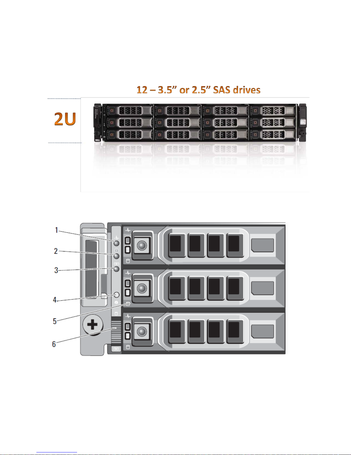
• MD3200i single controller model – A single RAID controller in a 2U, 12 drive 3.5” HDD enclosure
provides the lowest cost with the highest storage capacity offering when using large near-line
SAS drives.
• MD3200i dual controller model – Dual, active/active controllers in a 2U, 12 drive 3.5” HDD
enclosure provides a high availability and high capacity storage offering when using large nearline SAS drives.
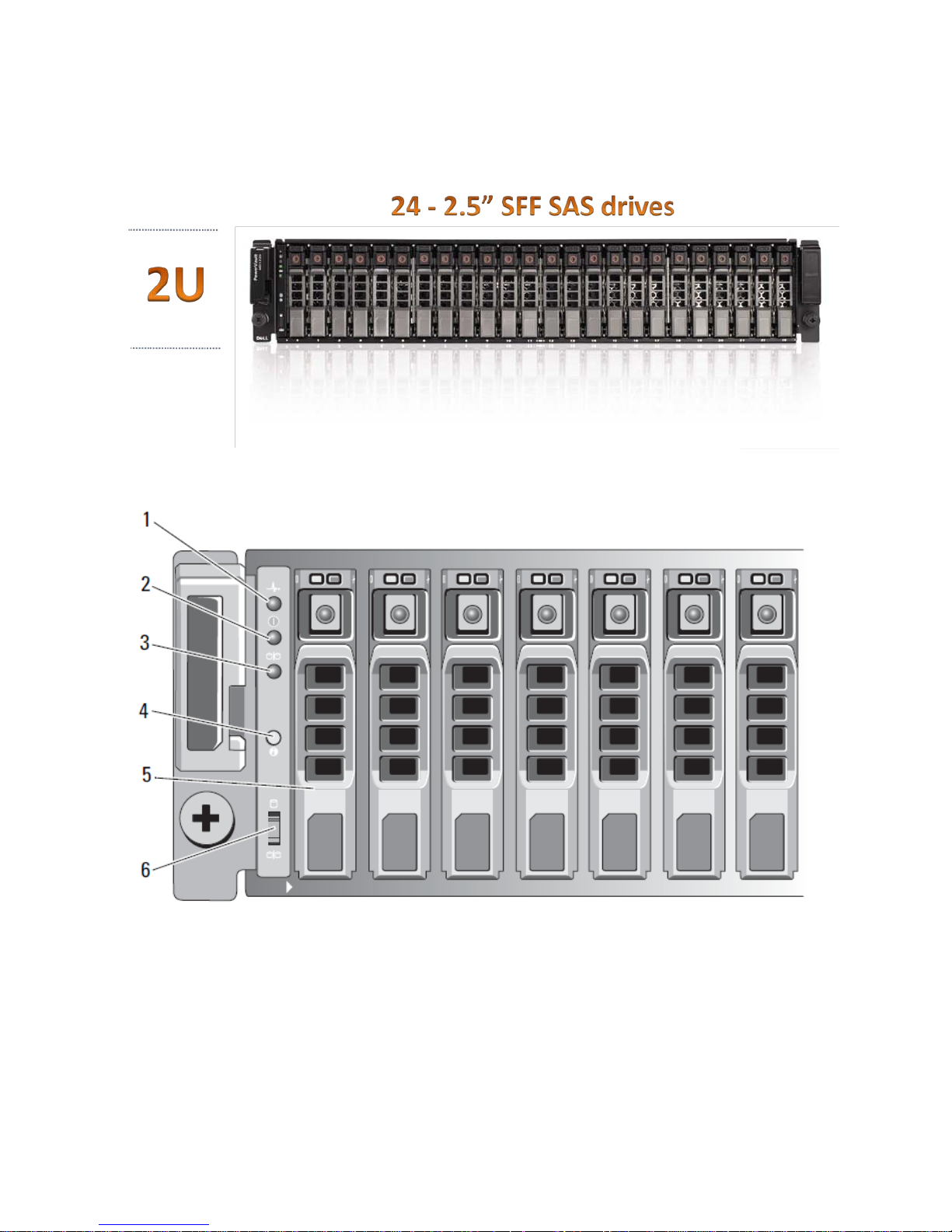
• MD3220i single controller model – A single RAID controller in a 2U, 24 drive 2.5” HDD enclosure
provides a low cost, high spindle count storage solution that maximizes IOPS when using SSD or
15K, 2.5” SAS drives.
• MD3220i dual controller model – Dual, active/active controllers in a 2U, 24 drive 2.5” HDD
enclosure provides the combination of a highly available storage solution with a high spindle
count to maximize IOPS when using SSD or 15K, 2.5” SAS drives.
This series of arrays raises the bar for scalability in the entry-level storage space. Each model is
capable of support up to 32 physical servers when connected to one or more 1Gb Ethernet switches.
Additional storage capacity can be added up to a maximum of 96 HDD via the MD1200 and/or MD1220
enclosures. Users can also mix 3.5” and 2.5” enclosures behind their base units in order to achieve the
optimal drive tiering that best matches their application needs. Within each enclosure users can mix
SSD, SAS and near-line SAS drives maximizing their return on investment.
In addition to the above mentioned features, the MD3200i series offers optional data protection
features like snap shots and virtual disk copy services to assist users in protecting their data in a more
effective manner. Initial set up is also much easier than the previous product with the addition of
wizard enabled tools and improvements in the Modular Disk Storage Manager.
iSCSI
iSCSI (Internet Small Computer System Interface) is an industry standard that allows SCSI block I/O
protocol to be sent over the network using a TCP/IP-based protocol for establishing and managing
connections between IP-based storage devices, hosts and clients. iSCSI SAN solutions (often called IP
SANs) consist of iSCSI initiators (software driver or adapter) in the application servers, connected to
iSCSI arrays by means of standard Gigabit Ethernet switches, routers and cables.
IP SANs are enabling organizations around the globe to maximize their existing IT investments while
deploying effective and efficient networked data management solutions. iSCSI is particularly
interesting as a SAN alternative to direct-attached storage in environments where simplicity,
flexibility, price/performance and availability of administrative staff are critical IT decision factors.
3

DELL PowerVault MD3200i/MD3220i Technical Guide Book
Advantages of iSCSI technology include:
• Expansive Reach
As a routable transport with no distance limitations, IP SANs can be located almost
anywhere. The reach of a SAN throughout the organization is most often limited by the
distance restriction of the interface. iSCSI removes these distance limitations to limitless
boundaries and extends its scope well beyond the corporate data center to remote locations
as well.
• Minimal Investment
iSCSI allows businesses to control their storage expenses without completely retro-fitting
their existing network. iSCSI creates IP-based SANs which allows organizations to capitalize
on components of their existing IP infrastructure by delivering block based storage across an
IP network. Organizations do not have to invest in a new storage-only infrastructure, such as
with FC which can be costly
• Enormous Knowledge and Experience Base
iSCSI allows almost all organizations to capitalize on existing IT skill sets to create IP-based
SANs as in-house networking expertise is standard throughout most companies today. An
end user does not have to learn a new networking protocol and go through extensive and
sometimes expensive training, such as with FC. As a mature, well-understood technology
with a broad range of proven management tools, iSCSI is easily deployed by administrators
with LAN experience.
6Gb Serial Attache d SCSI (SAS 2.0)
SAS provides a scalable point-to-point topology capable of addressing storage connectivity at many
levels. As SAS enters its second generation, the standard is evolving to enable better bandwidth
utilization, easier management mechanisms, and network robustness.
6Gb/s SAS 2.0 not only doubles the current data transfer rate it provides standardized zoning, selfdiscovery, and self-configuration methods to expanders. This makes larger and more complex
topologies easier than ever to implement.
Key features of SAS 2.0
• 6Gb/s SAS Signaling – doubles the transfer rate from 3Gb/s to 6Gb/s
• DFE (Decision Feedback Equalization) – increases cable limit to 10m ( 2 – 4 is typical)
• Supports SAS mini connectors (SFF-8088 and SFF-8087)
• SSC (Spread Spectrum Clocking ) – ease of design implementation – reduce peak amplitude of
radiated emissio ns
• Supports SED (Self-Encrypting Drive) with Instant Secure Erase
• Delivers 2
• Standardized Zoning
• Expanded to 256 devices
• Discovery executed by SAS Expanders
• Reduces time to discover large topologies
nd
generation SAS Discovery
4
DELL PowerVault MD3200i/MD3220i Technical Guide Book
SAS
Exp
SBB
2.0 Compliant Connector
2GB
DDR-II
1Gb Eth
NIC
RJ
45
I2C
32-lane 8-port
PCI-E Switch
PCI-E
PCI-E
DDR-II
X4
X24
(Drives)
X4
X4
(Alt Ctrl)
BBU
Cache Offload
Assembly
PCI-E
SD
FPGA
Flash
16 Bit Parallel Bus
NVSRAM
PCI-E
PCI-E
X4
(Alt Ctrl)
Flash
800MHz
Power PC
6Gb SAS
36 Port
Expander
iSCSI TOE
RJ45
RJ45 RJ45
RJ45
Controller Architecture
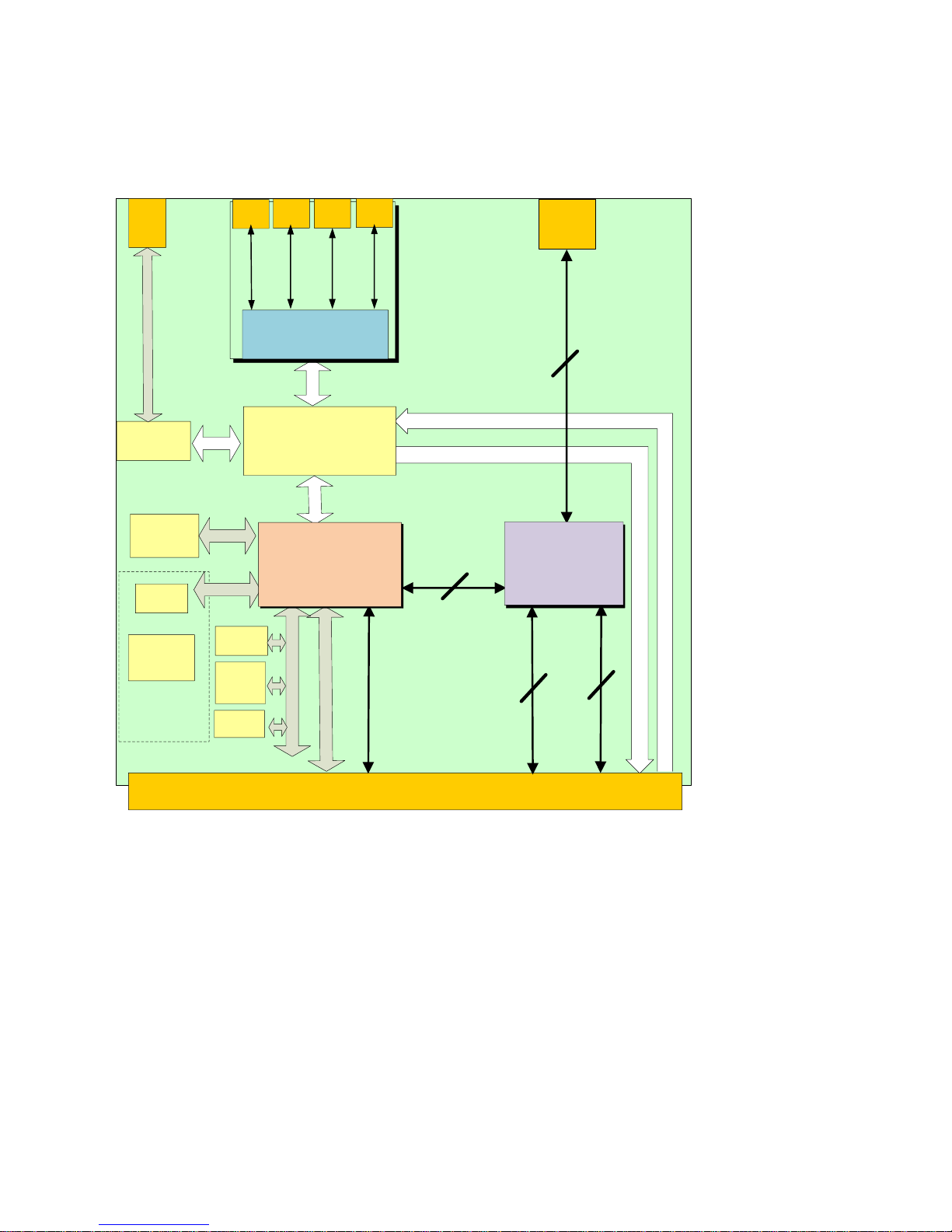
Figure 1. RAID controller architectur e of t he MD3200i controller.
The RAID controllers are the “engines” or the “brains” of the MD3200i and MD3220i storage arrays.
They perform the RAID calculations, control the I/O movement, communicate with the management
client, store the firmware, and protect data until it can be written safely to the hard disk drives. The
MD3200i’s architecture is designed to excel in multi-host systems environments. Its I/O system core
provides built-in ha rdware XOR for high-speed RAID parity calculations – enabling it to easily handle
very compute-intensive tasks. Each RAID controller contains 2GB of cache for a total of 4GB of cache
in a dual controller configuration which is mirrored with the other controller’s cache for high
availability. In the event of a power failure, the controllers are protected with battery assisted
persistent cache backup which destages cache to non-volatile media for indefinite safe keeping.
Each controller has a 36-port 6 Gb/s SAS expander that provides access to the drives in the MD3200i or
MD3220i enclosure. The SAS expanders enable each controller to access all of the drive ports creating
active/active drives loops that provide both controllers redundant access to all attached disk drives.
5
DELL PowerVault MD3200i/MD3220i Technical Guide Book
Power
Green
OFF = No power applie d
Controller Identifier
Blue
Indicates the location of the enclosure within the
Cache Active
Green
OFF = No data is in cache
1 2 3 4 5 6
l
1Gb Ethernet
1Gb Ethernet ports
6Gb SAS port for
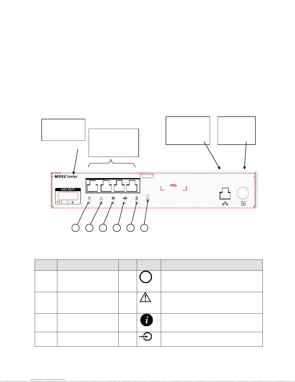
Each controller ha s the following external connections:
• Four 1Gb Ethernet ports for host connectivity
• One 6 Gb/s SAS port for drive enclosure expansion for additional capacity
• One Ethernet management ports for LAN out-of-band ma nag em e nt
• One PS/2 serial interface for service
Figure 2. MD3200i RAID Controller Mod ul e View - LEDs
drive expansion
for host
connectivity
port for
management
PS/2 serial
port for
service
Location LED Term Color Icon General Behavior
1
ON = Power is applied
Controller Fault Amber
2
OFF = The controller is operating normally
ON = The controller has defaulted
3
4
system.
6
DELL PowerVault MD3200i/MD3220i Technical Guide Book
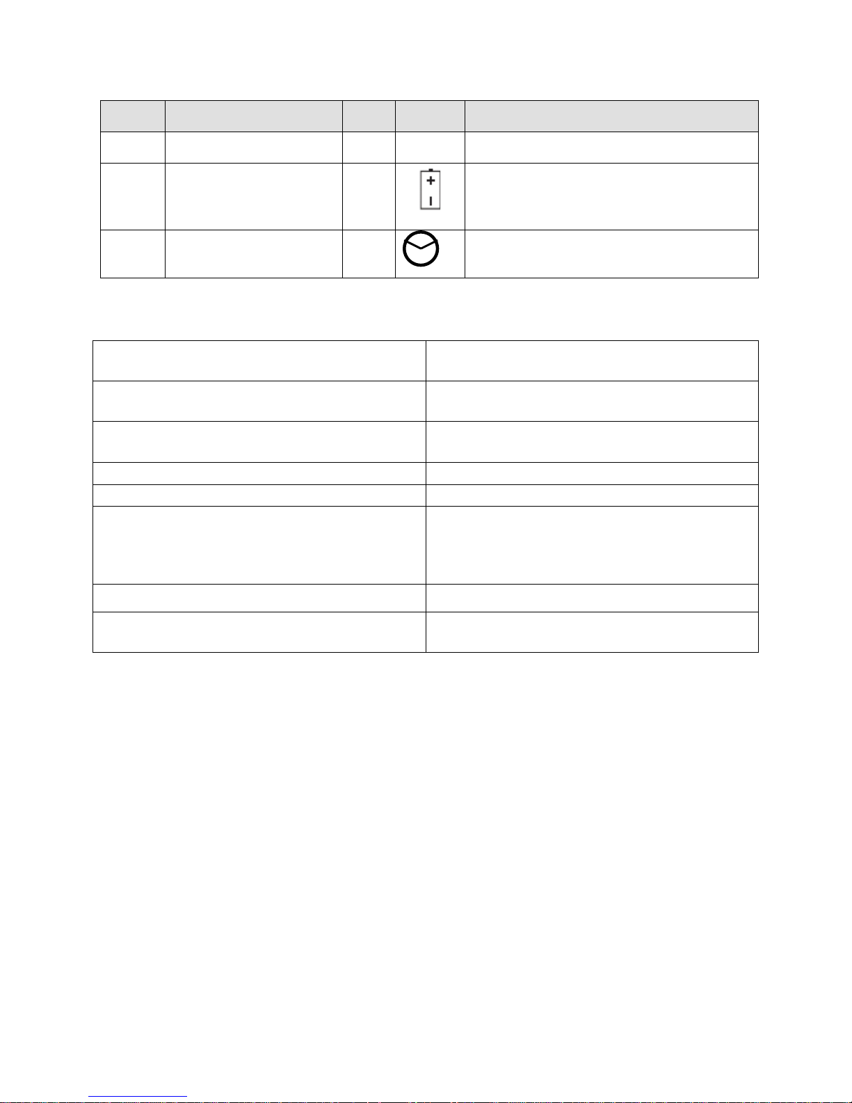
Location
LED Term
Color
Icon
General Behavior
ON = Data is in cache
Battery Fault
Amber
OFF = The battery is op erating normally
Password Reset Switch
Integrated storage partitioning, snapshot and
Dynamic disk group expansion
RAID levels 0, 1, 5, 6, 10
Dynamic virtual disk expansion
Greater than 2TB virtual disk size support
Dynamic RAID level migration
Smart battery allows the controller to monitor
Dynamic capacity expansion
Dynamic segment size migration
Dynamic defragmentation
5
6
N/A A button which allows the user to reset the
Table 1. Selected Controller Features:
Automated I/O path protection with host-based,
multipath failover drivers
Automatic drive failure detection and rebuild
using a global hot spare drive
virtual disk copy functionality
different parameters on the cache offload
batteries such as state-of-charge and state of
health
ON = The battery has d e faulted or is missing
default MD Storag e Manager password
One or more virtual disks per disk group
Up to 256 virtual disks
Up to 30 hard disk drives per disk group in a RAID5
and RAID6 and up to 96 drives in a RAID0 or RAID1
Non-disruptive firmware upgrades
7
DELL PowerVault MD3200i/MD3220i Technical Guide Book
Chassis
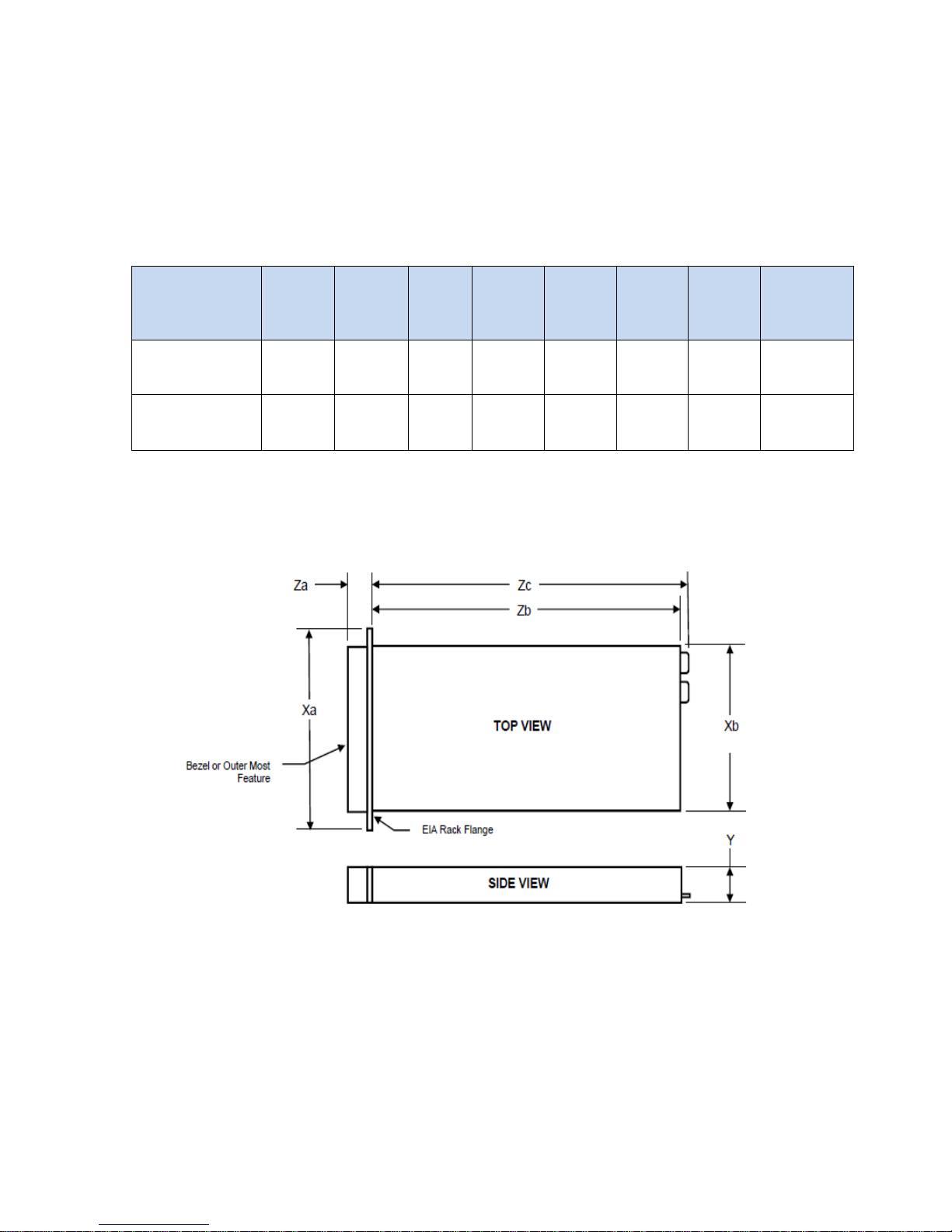
Dimensions and Weight
The PowerVault™ MD3200i and MD3220i enclosures use a rack mount 2U chassis.
Table 2. Detailed Dimensions (mm)
Model Number Xa Xb Y
Za
with
bezel
Za
with
bezel
Zb Zc
PV MD3200i 481.5 446.3 86.8 38.0 19.0 561.0 602.0 29.3
PV MD3220i 481.5 446.3 86.8 38.0 19.0 508.0 549.0 24.2
Figure 3. MD3200i and MD3220i Dimensions
Max Sys
Weight
(kg)
PowerVault™ MD3200i: Weight (maximum configuration) 29.3 kg (64.6 lb)
PowerVault™ MD3220i: Weight (maximum configuration) 24.2 kg (53.4 lb)
8
DELL PowerVault MD3200i/MD3220i Technical Guide Book
Figure 4. Front View and Features
MD3200i Front View an d Fea t u res
Figure 5. MD3200i Front Panel Indicators
9
DELL PowerVault MD3200i/MD3220i Technical Guide Book
Figure 6. MD3220i Front View an d Fea t u res
Figure 7. MD3200i Front Panel Indicators
10
 Loading...