

Dell PowerVault MD3200i, PowerVault MD3220i Owner's Manual

Dell PowerVault MD3200i and
MD3220i Storage Arrays With
Microsoft Windows Server
Failover Clusters
Hardware Installation
and
Troubleshooting Guide

Notes and Cautions
NOTE: A NOTE indicates important information that helps you make better use of
your computer.
CAUTION: A CAUTION indicates potential damage to hardware or loss of data if
instructions are not followed.
__________________
Information in this document is subject to change without notice.
© 2008–2010 Dell Inc. All rights reserved.
Reproduction of these materials in any manner whatsoever without the written permission of Dell Inc.
is strictly forbidden.
Trademarks used in this text: Dell™, the DELL logo, PowerEdge™, and PowerVault™ are trademarks
of Dell Inc. Microsoft
or registered trademarks of Microsoft Corporation in the United States and/or other countries.
Other trademarks and trade names may be used in this document to refer to either the entities claiming
the marks and names or their products. Dell Inc. disclaims any proprietary interest in trademarks and
trade names other than its own.
June 2010 Rev. A00
®
, Active Directory®, Windows®, and Windows Server® are either trademarks

Contents
1 Introduction . . . . . . . . . . . . . . . . . . . . . . . . 5
Overview . . . . . . . . . . . . . . . . . . . . . . . . . . 5
Cluster Solution . . . . . . . . . . . . . . . . . . . . . . 6
Cluster Requirements
Cluster Nodes
Cluster Storage
. . . . . . . . . . . . . . . . . . . 6
. . . . . . . . . . . . . . . . . . . . . 7
. . . . . . . . . . . . . . . . . . . . 8
Cluster Storage Management Software . . . . . . . 9
Supported Cluster Configurations . . . . . . . . . . . . 11
Other Documents You May Need
. . . . . . . . . . . . 13
2 Cabling Your Cluster Hardware . . . . . . . . 15
Cabling the Mouse, Keyboard, and Monitor . . . . . . 15
Cabling the Power Supplies
Cabling Your Public and Private Networks
Cabling Your Public Network
Cabling Your Private Network
Using Dual-Port Network Adapters
for Your Private Network
NIC Teaming
. . . . . . . . . . . . . . . . . . . . 20
Cabling the Storage Systems
Cabling the Cluster in Direct-Attached
Configuration
. . . . . . . . . . . . . . . . . . . . 21
. . . . . . . . . . . . . . . 15
. . . . . . . 18
. . . . . . . . . . . . 19
. . . . . . . . . . . 19
. . . . . . . . . . . . . . 20
. . . . . . . . . . . . . . 21
Contents 3

Cabling the Cluster in Network-Attached
Configuration . . . . . . . . . . . . . . . . . . . . 24
Connecting a PowerEdge Cluster to
Multiple PowerVault MD3200i or
MD3220i Storage Systems . . . . . . . . . . . . . 27
3 Preparing Your Systems for
Clustering . . . . . . . . . . . . . . . . . . . . . . . . 31
Cluster Configuration Overview . . . . . . . . . . . . . 31
Installation Overview
Installing the iSCSI NICs
Installing the Microsoft iSCSI
Software Initiator . . . . . . . . . . . . . . . . . . 35
Installing and Configuring the Storage
Management Software
Installing the Storage Management Software . . . 35
Configuring the Shared Storage System
Troubleshooting Tools
Configuring a Failover Cluster . . . . . . . . . . . 63
. . . . . . . . . . . . . . . . . . 33
. . . . . . . . . . . . . . 34
. . . . . . . . . . . . . . . 35
. . . . . . 37
. . . . . . . . . . . . . . . . 54
A Troubleshooting . . . . . . . . . . . . . . . . . . . 65
B Cluster Data Form . . . . . . . . . . . . . . . . . 71
C iSCSI Configuration Worksheet . . . . . . . 73
Index . . . . . . . . . . . . . . . . . . . . . . . . . . . . . . . 77
4 Contents

1
Introduction
This document provides information for installing and managing your
Cluster solution using Dell PowerVault MD3200i and MD3220i storage
systems. It is intended for experienced IT professionals who need to configure
the cluster solution, and for trained service technicians who perform upgrade
and maintenance procedures. This document also addresses readers who are
new to clustering.
Overview
A Microsoft Windows Server Failover Clustering combines specific hardware
and software components to provide enhanced availability for applications
and services that are run on the cluster. A failover cluster is designed to reduce
the possibility of any single point of failure within the system that can cause
the clustered applications or services to become unavailable. It is
recommended that you use redundant components like system and storage
power supplies, connections between the nodes and the storage array(s),
connections to client systems, or other systems in the multi-tier enterprise
application architecture in your cluster.
This guide addresses the configuration of your Dell MD3200i and MD3220i
iSCSI storage arrays for use with one or more Windows Server failover
clusters. It provides information and specific configuration tasks that enable
you to deploy the shared storage for your cluster.
For more information on deploying your cluster, see the Dell Failover Clusters
with Microsoft Windows Server Installation and Troubleshooting Guide at
support.dell.com/manuals.
NOTE: Throughout this document, Windows Server 2008 refers to Windows Server
2008 x64 Enterprise Edition or Windows Server 2008 R2 x64 Enterprise Edition.
For a list of recommended operating systems, hardware components, and
driver or firmware versions for your Dell Windows Server Failover Cluster, see
the Dell Cluster Configuration Support Matrices at dell.com/ha.
Introduction 5

Cluster Solution
Your iSCSI cluster implements a minimum of two-node clustering and a
maximum of sixteen-node clustering and provides the following features:
• Internet Small Computer System Interface (iSCSI) technology
• High availability of system services and resources to network clients
• Redundant paths to the shared storage
• Failure recovery for applications and services
• Flexible maintenance capabilities, allowing you to repair, maintain, or
upgrade a cluster node without taking the entire cluster offline
Implementing iSCSI technology in a cluster provides the following
advantages:
•
Flexibility
storage systems to be located at different sites.
•
Availability
multiple data paths and greater availability for clients.
•
Connectivity
iSCSI devices are hot-swappable, you can add or remove devices from the
nodes without bringing down the cluster.
—as iSCSI is based on TCP/IP, it allows cluster nodes and
—iSCSI components use redundant connections, providing
—iSCSI allows more device connections than SCSI. Because
Cluster Requirements
Your cluster requires the following components:
• Servers (cluster nodes)
• Storage and storage management software
6 Introduction

Cluster Nodes
Table 1-1 lists hardware requirements for the cluster nodes.
Table 1-1. Cluster Node Requirements
Component Minimum Requirement
Processor At least one processor for each cluster node.
Cluster Nodes A minimum of two identical PowerEdge systems.
RAM At least 1 GB RAM on each cluster node.
iSCSI Initiator Complete installation of the iSCSI port driver, Initiator Service,
and Software Initiator on each node.
NOTE: Microsoft Multipath I/O (MPIO) Multipathing Support for
iSCSI is not installed.
Network
Interface Cards
(NICs) for iSCSI
access
Two iSCSI NICs or NIC ports per node. Place the NICs on
separate PCI buses to improve availability and performance.
TCP/IP Offload Engine (TOE) NICs are also supported for iSCSI
traffic. For a list of recommended operating systems, hardware
components, and driver or firmware versions for your Dell
Windows Server Failover Cluster, see the Dell Cluster
Configuration Support Matrices at dell.com/ha.
Introduction 7

Table 1-1. Cluster Node Requirements
Component Minimum Requirement
NICs (public and
private)
At least two NICs: one NIC for the public network and another
NIC for the private network.
(continued)
NOTE: It is recommended that the NICs on each public network are
identical and that the NICs on each private network are identical.
Internal Disk
Controller
One controller connected to internal disks for each node. Use any
supported Redundant Array of Independent Disks (RAID)
controller or disk controller.
Two physical disks are required for mirroring (RAID 1) and at least
three are required for disk striping with parity (RAID 5).
NOTE: It is recommended that you use hardware-based RAID or
software-based disk-fault tolerance for the internal drives.
Cluster Storage
Table 1-2 provides the configuration requirements for the shared storage
system.
Table 1-2. Cluster Storage Requirements
Hardware
Components
Supported storage
systems
Power and cooling
requirements
Physical disks At least two physical disks in the PowerVault MD3200i or
Multiple clusters and
stand-alone systems
NOTE: RAID 0 and independent disks are possible but are not recommended for a
high-availability system because they do not offer data redundancy if a disk
failure occurs.
Minimum Requirement
One Dell PowerVault MD3200i or MD3220i RAID enclosure.
Up to seven Dell PowerVault MD1200 and MD1220 expansion
enclosures with a maximum of 96 disks.
Two integrated hot-swappable power supply/cooling fan
modules.
MD3220i RAID enclosure.
In a switch-attached configuration, clusters and stand-alone
systems can share one or more PowerVault MD3200i or
MD3220i systems.
8 Introduction

Cluster Storage Management Software
Dell PowerVault Modular Disk Storage Manager
The software runs on the management station or any host attached to the
array to centrally manage the PowerVault MD3200i and MD3220i RAID
enclosures. You can use Dell PowerVault Modular Disk Storage Manager
(MDSM) to perform tasks such as creating or managing RAID arrays, binding
virtual disks, and downloading firmware.
MDSM is a graphical user interface (GUI) with wizard-guided tools and a
task-based structure. MDSM is designed to:
• Reduce the complexity of installation, configuration, management, and
performing diagnostic tasks for the storage arrays.
• Contain an event monitoring service that is used to send alerts when a
critical problem with the storage array occurs.
• Provide a command line interface (CLI) to run commands from an
operating system prompt.
Modular Disk Storage Manager Agent
This software resides on each cluster node to collect system-based topology
data that can be managed by the MDSM.
Multipath Software
Multipath I/O software (also referred to as the failover driver) is a software
residing on each cluster node that provides management of the redundant
data path between the system and the RAID enclosure. For the multipath
software to correctly manage a redundant path, the configuration must
provide for redundant NICs and cabling.
The multipath software identifies the existence of multiple paths to a virtual
disk and establishes a preferred path to that disk. If any component in the
preferred path fails, the multipath software automatically re-routes I/O
requests to the alternate path so that the storage array continues to operate
without interruption.
Introduction 9

Advanced Features
Advanced features for the PowerVault MD3200i and MD3220i RAID storage
systems include:
•
Snapshot Virtual Disk
—Captures point-in-time images of a virtual disk
for backup, testing, or data processing without affecting the contents of
the source virtual disk.
•
Virtual Disk Copy
—generates a full copy of data from the source virtual
disk to the target virtual disk in a storage array. You can use Virtual Disk
Copy to back up data, copy data from disk groups that use smaller-capacity
physical disks to disk groups using greater capacity physical disks, or restore
snapshot virtual disk data to the source virtual disk.
NOTE: For instructions on deploying the correct options in the cluster
environment, see "Using Advanced (Premium) PowerVault Modular Disk
Storage Manager Features" on page 61.
10 Introduction
Supported Cluster Configurations
Node N
Node 1 ....................
corporate, public, or
private network
MD32xxi RAID
controller module 0
MD32
xx
i RAID
controller module 1
storage array
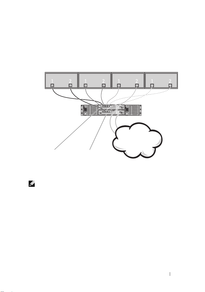
Figure 1-1. Direct-Attached Cluster Configuration
NOTE: The configuration can have up to four nodes (N is either 2, 3, or 4). The
nodes can be:
• one cluster
• two different clusters
• one cluster and stand-alone server(s)
Introduction 11
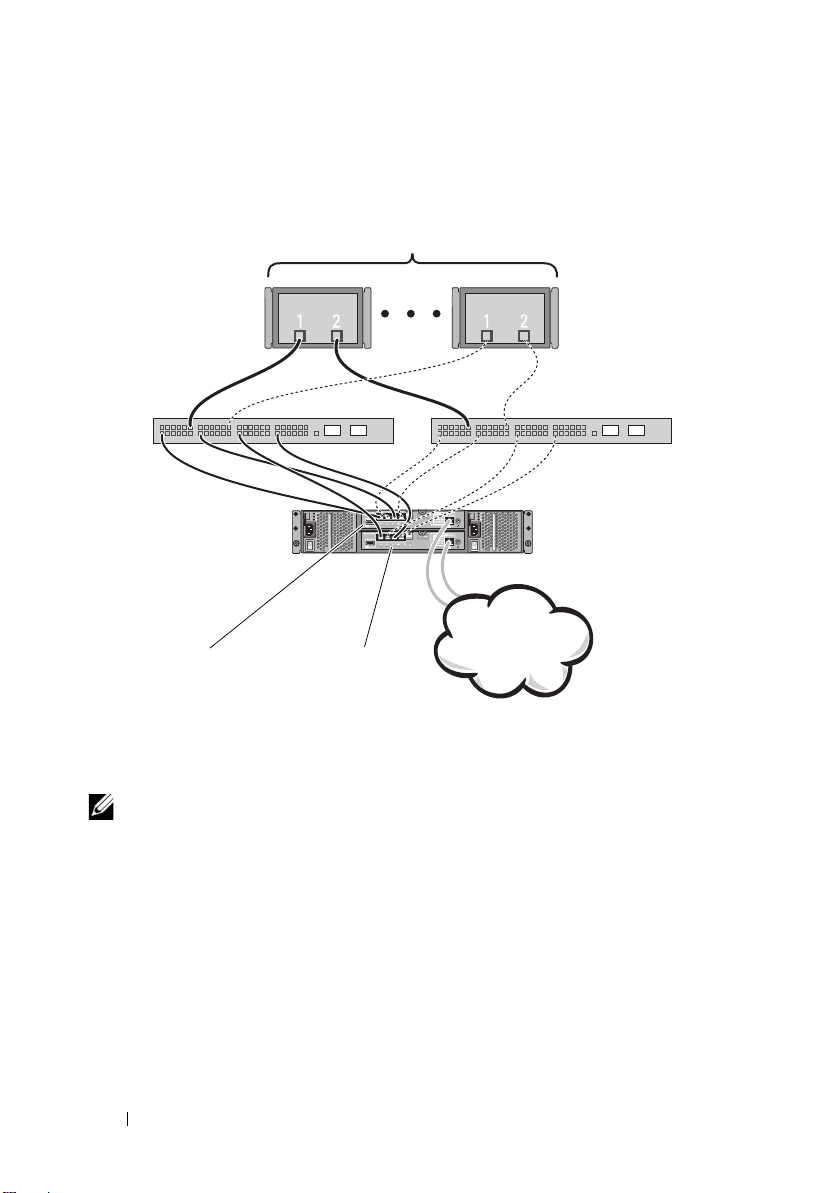
Figure 1-2. Redundant Network-Attached Cluster Configuration
corporate, public,
or private network
storage array
G
i
g
a
b
i
t
E
t
h
e
r
n
e
t
s
w
i
t
c
h
1
MD32xxi RAID
controller module 0
MD32xxi RAID
controller module 1
G
i
g
a
b
i
t
E
t
h
e
r
n
e
t
s
w
i
t
c
h
2
up to 32 hosts
12 Introduction
NOTE: The configuration can have up to 32 nodes. The nodes can be:
• one cluster (up to 16 nodes)
• multiple clusters
• multiple cluster(s) and stand-alone server(s)

Other Documents You May Need
CAUTION: The safety information that shipped with your computer provides
important safety and regulatory information. Warranty information may be
included within this document or as a separate document.
NOTE: To configure Dell blade system modules in a Dell PowerEdge Cluster,
see the
Using Dell Blade Servers in a Dell PowerEdge High Availability Cluster
document at support.dell.com/manuals.
•The
Rack Installation Guide
included with your rack solution describes
how to install your system into a rack.
•The
Getting Started Guide
provides an overview to initially set up
your system.
•The
Dell Failover Clusters with Microsoft Windows Server 2008 Installation
and Troubleshooting Guide
provides more information about deploying
your cluster.
•The
Dell Cluster Configuration Support Matrices
provides a list of
recommended operating systems, hardware components, and driver or
firmware versions for your Dell Windows Server Failover Cluster.
• The operating system documentation describes how to install (if
necessary), configure, and use the operating system software.
•The
Dell PowerVault MD3200i and MD3220i RAID Enclosures Owner’s
Manual
provides instructions for using the array management software to
configure RAID systems.
• Documentation for any components you purchased separately provides
information to configure and install those options.
• The Dell PowerVault tape library documentation provides information for
installing, troubleshooting, and upgrading the tape library.
• Updates are sometimes included with the system to describe changes to
the system, software, and/or documentation.
• The User's Guide for your PowerEdge system describes system features
and technical specifications, the System Setup program (if applicable),
software support, and the system configuration utility.
•The
Dell PowerVault MD3200i and MD3220i Owner's Manual
provides
information about the hardware enclosure.
Introduction 13

•The
PowerVault Modular Disk Storage Manager CLI Guide
provides
information about using the CLI.
•The
Dell PowerVault MD3200i and MD3220i Resource
DVD provides
documentation for configuration and management tools, as well as the full
documentation set included here.
•The
Dell PowerVault MD Getting Started Guide
provides an overview of
setting up and cabling your storage array.
•The
Dell PowerVault MD3200i and MD3220i Storage Arrays Deployment
Guide
provides installation and configuration instructions to configure the
storage system for initial use.
•The
Dell PowerVault MD Systems Support Matrix
provides information on
supported software and hardware for PowerVault MD systems.
NOTE: Always read the updates first because they often supersede
information in other documents.
• Release notes or readme files may be included to provide last-minute
updates to the system documentation or advance technical reference
material intended for experienced users or technicians.
14 Introduction

2
Cabling Your Cluster Hardware
The following sections provide information on how to cable various
components of your cluster.
Cabling the Mouse, Keyboard, and Monitor
When installing a cluster configuration in a rack, you must include a switch
box to connect the mouse, keyboard, and monitor to the nodes. See the
documentation included with your rack for instructions on cabling each
node's connections to the switch box.
Cabling the Power Supplies
To ensure that the specific power requirements are satisfied, see the
documentation for each component in your cluster solution.
It is recommended that you adhere to the following guidelines to protect your
cluster solution from power-related failures:
• For nodes with multiple power supplies, plug each power supply into a
separate AC circuit.
• Use uninterruptible power supplies (UPS).
• For some environments, consider having backup generators and power
from separate electrical substations.
Figure 2-1 and Figure 2-2 illustrate recommended methods for power cabling
of a cluster solution consisting of two Dell PowerEdge systems and one
storage system. To ensure redundancy, the primary power supplies of all the
components are grouped onto one or two circuits and the redundant power
supplies are grouped onto a different circuit.
Cabling Your Cluster Hardware 15
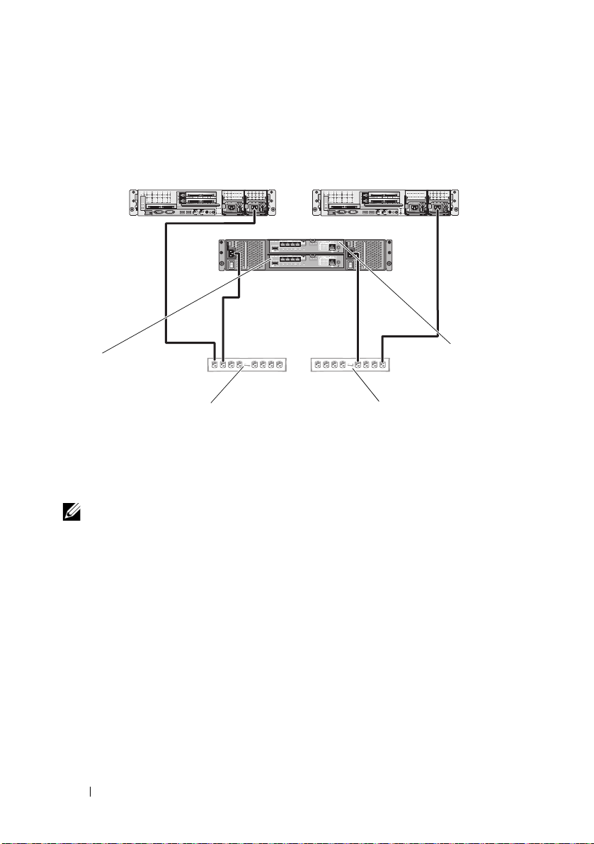
Figure 2-1. Power Cabling Examples With One Power Supply in the PowerEdge
primary power supplies on one
AC power strip (or one AC PDU
[not shown])
redundant power supplies on one
AC power strip (or one AC PDU
[not shown])
MD32xxi
RAID
controller
module 1
MD32
xx
i
RAID
controller
module 0
MD32xxi
RAID
controller
module 1
Systems
NOTE: This illustration is intended only to demonstrate the power distribution of the
components.
16 Cabling Your Cluster Hardware
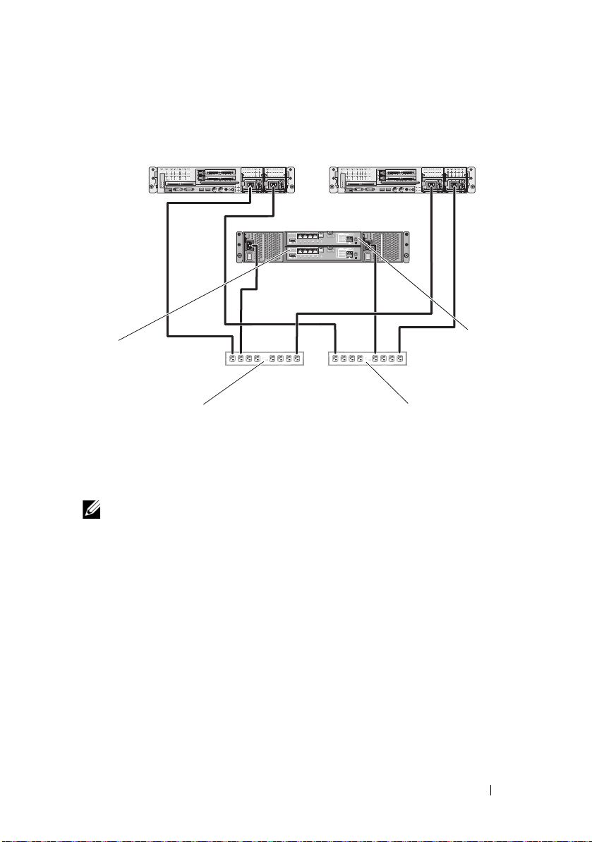
Figure 2-2. Power Cabling Example With Two Power Supplies in the PowerEdge
primary power supplies on one
AC power strip (or one AC PDU
[not shown])
redundant power supplies on one
AC power strip (or one AC PDU
[not shown])
MD32xxi
RAID
controller
module 0
MD32xxi
RAID
controller
module 1
Systems
NOTE: This illustration is intended only to demonstrate the power distribution of the
components.
Cabling Your Cluster Hardware 17

Cabling Your Public and Private Networks
The network adapters in the cluster nodes provide at least two network
connections for each node. These connections are described in Table 2-1.
Table 2-1. Network Connections
Network Connection Description
Public Network All connections to the client LAN.
At least one public network must be configured for
mixed mode (public mode and private mode) for
private network failover.
Private Network A dedicated connection for sharing cluster health and
status information between the cluster nodes.
Network adapters connected to the LAN can also
provide redundancy at the communications level in
case the cluster interconnect fails.
See your Microsoft Failover Clustering
documentation for more information on private
network redundancy.
Figure 2-3 shows an example of network adapter cabling in which dedicated
network adapters in each node are connected to the public network and the
remaining network adapters are connected to each other (for the private
network).
18 Cabling Your Cluster Hardware
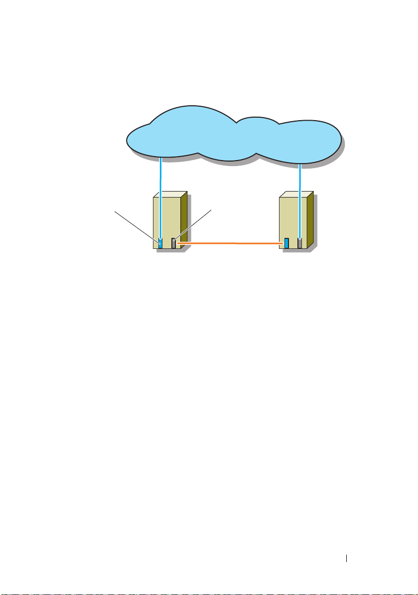
Figure 2-3. Example of Network Cabling Connection
public network
p
u
b
l
i
c
n
e
t
w
o
r
k
a
d
a
p
t
e
r
private network
adapter
cluster node 1 cluster node 2
private network
Cabling Your Public Network
Any network adapter supported by a system running TCP/IP may be used to
connect to the public network segments. You can install additional network
adapters to support additional public network segments or to provide
redundancy in the event of a faulty primary network adapter or switch port.
Cabling Your Private Network
The private network connection to the cluster nodes is provided by a second
or subsequent network adapter that is installed in each node. This network is
used for intra-cluster communications.
Table 2-2 lists the required hardware components and connection method for
three possible private network configurations.
Cabling Your Cluster Hardware 19

Table 2-2. Private Network Hardware Components and Connections
Method Hardware Components Connection
Network switch Gigabit or 10 Gigabit
Ethernet network
adapters and switches.
Point-to-Point (two node
cluster only)
NOTE: Throughout this document, Ethernet refers to either Gigabit Ethernet or
10 Gigabit Ethernet.
Copper Gigabit or 10
Gigabit Ethernet network
adapters with RJ-45
connectors.
Copper 10 Gigabit
Ethernet network
adapters with SFP+
connectors
Optical Gigabit or 10
Gigabit Ethernet network
adapters with LC
connectors
Depending on the hardware,
connect the CAT5e or CAT6
cables, the multimode optical
cables with Local Connectors
(LCs), or the twinax cables
from the network adapters in
the nodes to a switch.
Connect a standard CAT5e or
CAT6 Ethernet cable between
the network adapters in both
nodes.
Connect a twinax cable
between the network adapters
in both nodes.
Connect a multi-mode optical
cable between the network
adapters in both nodes.
Using Dual-Port Network Adapters for Your Private Network
You can configure your cluster to use the public network as a failover for
private network communications. However, if dual-port network adapters are
used, do not use two ports simultaneously to support both the public and
private networks.
NIC Teaming
Network Interface Card (NIC) teaming combines two or more NICs to
provide load balancing and/or fault tolerance. Your cluster supports NIC
teaming, but only in a public network; NIC teaming is not supported in a
private network.
20 Cabling Your Cluster Hardware

You must use the same brand of NICs in a team, and you cannot mix brands
of teaming drivers.
Cabling the Storage Systems
This section provides information for connecting your cluster to a storage
system.
NOTE: To configure Dell blade system modules in a Dell PowerEdge Cluster, see
Using Dell Blade Servers in a Dell PowerEdge High Availability Cluster
support.dell.com/manuals.
NOTE: For more details on storage hardware settings and descriptions, see
Dell PowerVault MD3200i and MD3220i RAID Enclosure Owner's Manual
support.dell.com/manuals.
Storage management can be either in-band through the host-to-controller
interface or out-of-band using an Ethernet connection. For out-of-band
storage management, cable the Ethernet ports on the storage array to the
public network.
NOTE: It is recommended that you configure your Dell PowerVault MD3200i and
MD3220i to use out-of-band management.
Cabling the Cluster in Direct-Attached Configuration
In the direct-attached configuration, each cluster node is directly attached to
the PowerVault MD3200i or MD3220i RAID controller modules using two
network cables, and either one dual-port NIC or two single-port NICs.
If a component fails in the storage path such as the port, the cable, or the
storage controller, the multipath software automatically re-routes the I/O
requests to the alternate path so that the storage array continues to operate
without interruption. The configuration with two single-port NICs provides
higher availability; a NIC failure does not cause failover cluster to move
cluster resources to the other cluster node.
To cable the cluster:
1
Connect cluster node 1 to the storage system:
a
Install a network cable from the cluster node 1 iSCSI NIC 1 (or NIC
port 1) to the RAID controller module 0 port In-0.
at
at
Cabling Your Cluster Hardware 21

b
Install a network cable from the cluster node 1 iSCSI NIC 2 (or NIC
port 2) to the RAID controller module 1 port In-1.
2
Connect cluster node 2 to the storage system:
a
Install a network cable from the cluster node 2 iSCSI NIC 1 (or NIC
port 1) to the RAID controller module 1 port In-0.
b
Install a network cable from the cluster node 2 iSCSI NIC 2 (or NIC
port 2) to the RAID controller module 0 port In-1.
3
If applicable, connect node 3 to the storage system. Node 3 can be either
cluster node 3 of the only cluster in the configuration, cluster node 1 of the
second cluster, or a stand-alone server.
a
Install a network cable from the cluster node 3 iSCSI NIC 1 (or NIC
port 1) to the RAID controller module 0 port In-2.
b
Install a network cable from the cluster node 3 iSCSI NIC 2 (or NIC
port 2) to the RAID controller module 1 port In-3.
4
If applicable, connect node 4 to the storage system. Node 4 can be either
cluster node 4 of the only cluster in the configuration, cluster node 2 of the
second cluster, or a stand-alone server.
a
Install a network cable from the cluster node 4 iSCSI NIC 1 (or NIC
port 1) to the RAID controller module 1 port In-2.
b
Install a network cable from the cluster node 4 iSCSI NIC 2 (or NIC
port 2) to the RAID controller module 0 port In-3.
22 Cabling Your Cluster Hardware
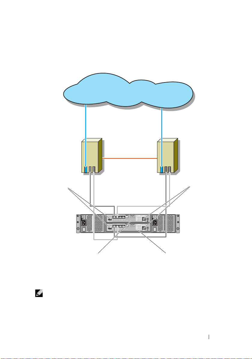
Figure 2-4. Direct-Attached Cluster Configuration
MD32xxi RAID controller
module 0
cluster node 2
cluster node 1
private network
public network
Ethernet
management
port (2)
SAS out port (2)
MD32xxi RAID controller
module 1
NOTE: The SAS out port provides SAS connection for cabling to MD1200 or MD1220
expansion enclosure(s).
Cabling Your Cluster Hardware 23

Cabling the Cluster in Network-Attached Configuration
In the network-attached configuration, each cluster node attaches to the
storage system using redundant IP storage area network (SAN) industrystandard 1 Gb Ethernet switches, and either with one dual-port iSCSI NIC or
two single-port iSCSI NICs. If a component fails in the storage path such as
the iSCSI NIC, the cable, the switch, or the storage controller, the multipath
software automatically re-routes the I/O requests to the alternate path so that
the storage array continues to operate without interruption. The
configuration with two single-port NICs provides higher availability; a NIC
failure does not cause Microsoft Failover Cluster to move cluster resources to
the other cluster node.
This configuration can support up to 32 hosts simultaneously. Examples of
this configuration are:
•One cluster.
•Two clusters.
• One eight-node cluster, two two-node clusters, and one stand-alone
system.
To cable the cluster:
1
Connect the storage system to the iSCSI network:
a
Install a network cable from switch 1 to controller 0 port In-0.
b
Install a network cable from switch 1 to controller 1 port In-0.
c
Install a network cable from switch 2 to controller 0 port In-1.
d
Install a network cable from switch 2 to controller 1 port In-1.
e
Install a network cable from switch 1 to controller 0 port In-2.
f
Install a network cable from switch 1 to controller 1 port In-2.
g
Install a network cable from switch 2 to controller 0 port In-3.
h
Install a network cable from switch 2 to controller 1 port In-3.
2
Connect the cluster to the iSCSI network:
a
Install a network cable from the cluster node 1 iSCSI NIC 1 (or NIC
port 1) to the network switch 1.
b
Install a network cable from the cluster node 1 iSCSI NIC 2 (or NIC
port 2) to the network switch 2.
24 Cabling Your Cluster Hardware
 Loading...