

Page 1

Dell PowerVault MD3200i and
MD3220i Storage Arrays
Getting Started
With Your System
Guide de mise en route
Introdução ao uso do sistema
Introducción al sistema
Page 2

Page 3

Dell PowerVault MD3200i and
MD3220i Storage Arrays
Getting Started
With Your System
Regulatory Model Series E03J and E04J
Page 4

Notes, Cautions, and Warnings
NOTE:
A NOTE indicates important information that helps you make better use
of your computer.
CAUTION:
if instructions are not followed.
WARNING:
personal injury, or death.
____________________
Information in this publication is subject to change without notice.
© 2011 Dell Inc. Allrightsreserved.
Reproduction of these materials in any manner whatsoever without the written permission of Dell Inc.
is strictly forbidden.
Trademarks used in this text: Dell™, the DELL logo, and PowerVault™ are trademarks of Dell Inc.
Microsoft
Corporation in the United States and/or other countries. Red Hat
registered trademarks of Red Hat, Inc. in the United States and other countries. SUSE
trademark of Novell, Inc. in the United States and other countries. VMware
of VMware, Inc. in the United States and/or other jurisdictions.
Other trademarks and trade names may be used in this publication to refer to either the entities claiming
the marks and names or their products. Dell Inc. disclaims any proprietary interest in trademarks and
trade names other than its own.
®
A CAUTION indicates potential damage to hardware or loss of data
A WARNING indicates a potential for property damage,
and Windows Server® are either trademarks or registered trademarks of Microsoft
®
and Red Hat Enterprise Linux® are
®
®
is a registered trademark
is a registered
Regulatory Model Series E03J and E04J
2011 - 08 P/N TFKD1 Rev. A02
Page 5

Before You Begin
NOTE:
Throughout the document, Dell PowerVault MD3200i series storage array
refers to both Dell PowerVault MD3200i and Dell PowerVault MD3220i. Dell
PowerVault MD1200 series expansion enclosure refers to both Dell PowerVault
MD1200 and Dell PowerVault MD1220.
Before setting up your Dell PowerVault MD3200i series storage array,
you must consider certain best practices to ensure that your storage array
operates at maximum efficiency and offers full redundancy (if required).
• It is recommended that you use a dedicated IP SAN for iSCSI data
transmission. Management traffic can be isolated on a separate
management network.
• Complete the iSCSI configuration worksheet before configuring iSCSI.
See "Completing the iSCSI Worksheet" on page 4. This worksheet gathers
physical network information in a single source.
• After completing the iSCSI worksheet, draw the configuration before
setting up the solution.
• Always configure redundant iSCSI data paths to provide alternate paths to
and from the host server should one of the data paths become disabled.
• If multiple NICs are installed on a host, it is recommeded that you use
different subnets for management and iSCSI data links.
• Throughout the network, always use a Category 5e (or higher)
Ethernet cable.
• Before connecting any cables between the host server and storage array,
physically label each port and connector.
• Always follow proper power-up and power-down procedures when cycling
power across the network. You must also ensure that critical network
components are on separate power circuits.
NOTE:
The illustrations in this document show cabling for only one PowerVault
MD3200i series storage array in a SAN environment. The illustrations also show
only the default IP addresses for the PowerVault MD3200i series storage array. To
cable more than one PowerVault MD3200i series storage array in a SAN
environment, see the Deployment Guide.
Getting Started With Your System
3
Page 6
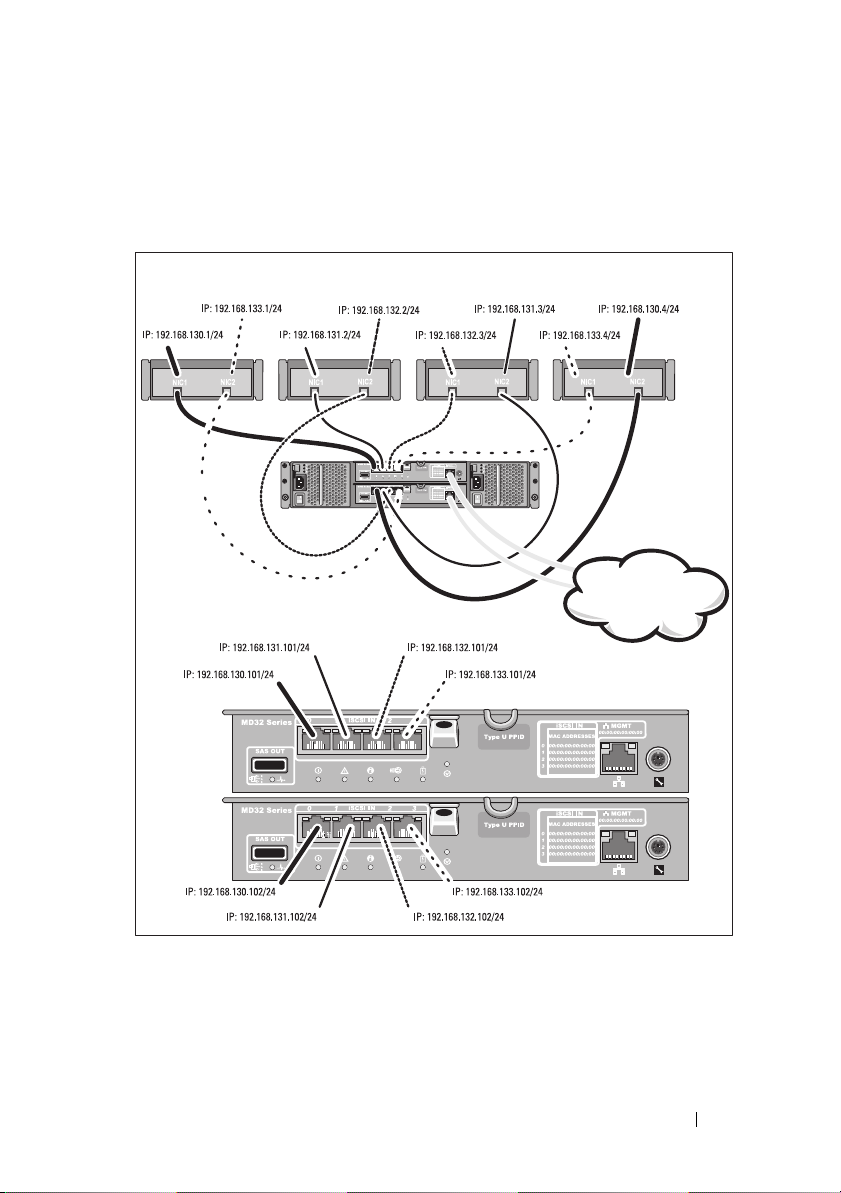
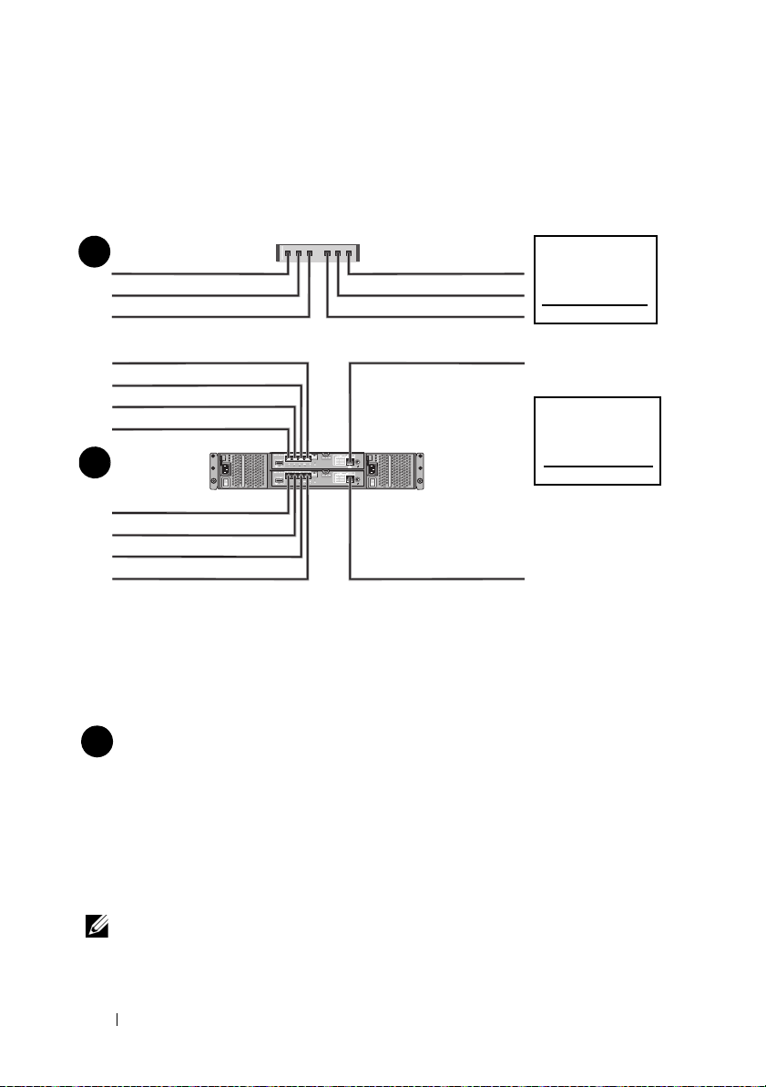
Completing the iSCSI Worksheet
Mutual
CHAP Secret
Target CH AP
Secret
A
B
host server
PowerVault
MD3200i series
storage array
192.168.130.101 (In 0 default)
192.168.131.101 (In 1 default)
192.168.132.101 (In 2 default)
192.168.133.101 (In 3 default)
192.168.128.101 (management network port)
192.168.130.102 (In 0 default)
192.168.131.102 (In 1 default)
192.168.132.102 (In 2 default)
192.168.133.102 (In 3 default)
192.168.128.102 (management network port)
If you need additional space for more than one host server, use an additional sheet.
iSCSI port 1
iSCSI port 2
iSCSI port 3
iSCSI port 4
Management port
Static IP address (host server)
Subnet mask
Default gateway
A
___ . ___ . ___ . ___
___ . ___ . ___ . ___
___ . ___ . ___ . ___
___ . ___ . ___ . ___
___ . ___ . ___ . ___
___ . ___ . ___ . ___
___ . ___ . ___ . ___
___ . ___ . ___ . ___
___ . ___ . ___ . ___
___ . ___ . ___ . ___
___ . ___ . ___ . ___
___ . ___ . ___ . ___
___ . ___ . ___ . ___
___ . ___ . ___ . ___
___ . ___ . ___ . ___
NOTE:
The host server can support up to four NICs.
IPv4 Settings
4
Getting Started With Your System
Page 7
Static IP address (storage array)
Subnet mask
Default gateway
B
___ . ___ . ___ . ___
___ . ___ . ___ . ___
___ . ___ . ___ . ___
___ . ___ . ___ . ___
___ . ___ . ___ . ___
___ . ___ . ___ . ___
___ . ___ . ___ . ___
___ . ___ . ___ . ___
___ . ___ . ___ . ___
___ . ___ . ___ . ___
iSCSI controller 0, In 0
iSCSI controller 0, In 1
iSCSI controller 0, In 2
iSCSI controller 0, In 3
Management port cntrl 0
iSCSI controller 1, In 0
iSCSI controller 1, In 1
iSCSI controller 1, In 2
iSCSI controller 1, In 3
Management port cntrl 1
___ . ___ . ___ . ___
___ . ___ . ___ . ___
___ . ___ . ___ . ___
___ . ___ . ___ . ___
___ . ___ . ___ . ___
___ . ___ . ___ . ___
___ . ___ . ___ . ___
___ . ___ . ___ . ___
___ . ___ . ___ . ___
___ . ___ . ___ . ___
___ . ___ . ___ . ___
___ . ___ . ___ . ___
___ . ___ . ___ . ___
___ . ___ . ___ . ___
___ . ___ . ___ . ___
___ . ___ . ___ . ___
___ . ___ . ___ . ___
___ . ___ . ___ . ___
___ . ___ . ___ . ___
___ . ___ . ___ . ___
NOTE:
Other Documentation and Media You May Need
WARNING:
your system. Warranty information may be included within this document or
as a separate document.
NOTE:
support.dell.com/manuals.
• The rack documentation included with your rack solution describes how
to install your system into a rack.
• The
describes how to troubleshoot the system and install or replace system
components.
• The
configuring the software and hardware.
• The
interface (CLI) to configure and manage your storage array.
For information about the IPv6 worksheet, see the Deployment Guide.
See the safety and regulatory information that shipped with
All PowerVault MD3200i series storage array documents are available at
Owner’s Manual
Deployment Guide
CLI Guide
provides information about system features and
provides information about installing and
provides information about using the command line
Getting Started With Your System
5
Page 8
•The
• Any media that ships with your system that provides documentation and tools
SMI-S Programmer’s Guide
the SMI-S provider and SMI-S programming.
for configuring and managing your system, including those pertaining to the
operating system, system management software, system updates, and system
components that you purchased with your system.
NOTE:
Always check for updates on support.dell.com/manuals and read the
updates first because they often supersede information in other documents.
provides information about using
Preparing the Host Server
Supported Operating Systems
• Microsoft Windows Server
• Red Hat Enterprise Linux
• SUSE Linux Enterprise Server
• VMware
NOTE:
For the latest information on all supported operating system versions,
see the Support Matrix at support.dell.com/manuals.
Additional NICs for iSCSI
When installing additional NICs, it is recommended that:
• You use dedicated redundant storage networks for iSCSI traffic.
If a dedicated network is not feasible, isolate the iSCSI traffic from
general network traffic using virtual local area networks (VLAN).
• You use additional NICs dedicated for iSCSI traffic.
• The NICs must be added in pairs for redundancy (up to four NICs).
NOTE:
A single NIC is also supported.
NIC Configuration
In a SAN environment, depending on the number of switches, it is
recommended that you use two or four unique subnets for iSCSI traffic.
For direct-attached storage environments, each NIC directly connected to
the PowerVault MD3200i series storage array must be on a separate subnet.
6
Getting Started With Your System
Page 9
Common Configurations
Server 1 Server 2
Storage array
Server 3 Server 4
Corporate, public,
or private network
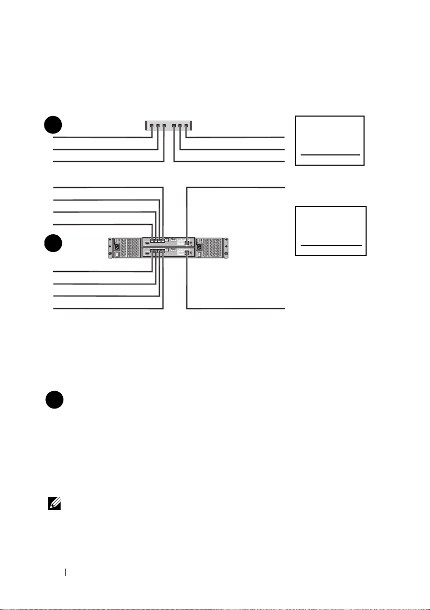
Cabling Your Direct-Attached Hosts
Getting Started With Your System
7
Page 10
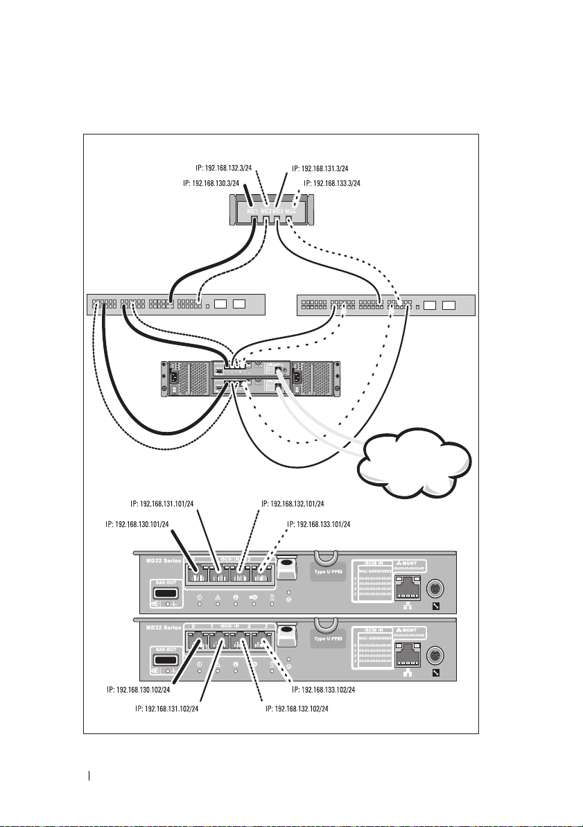
Cabling Your SAN-Attached Hosts
Storage array
Corporate, public,
or private network
Switch 1 Switch 2
Server
8
Getting Started With Your System
Page 11
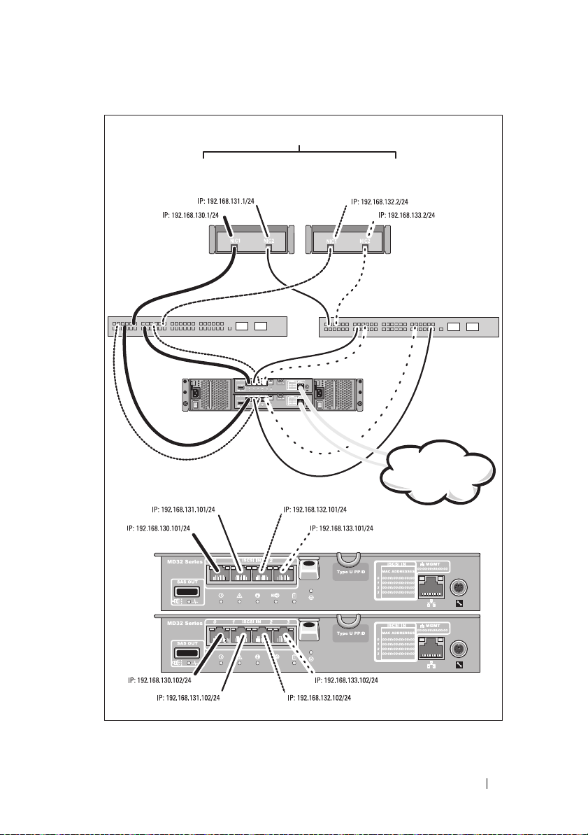
Up to 32 hosts
Server 1 Server 2
Storage array
Corporate, public,
or private network
Switch 1 Switch 2
Getting Started With Your System
9
Page 12
Installation and Configuration
WARNING:
instructions that came with the system.
Unpacking the System
Unpack your system and identify each item with the packing list that shipped
with your system.
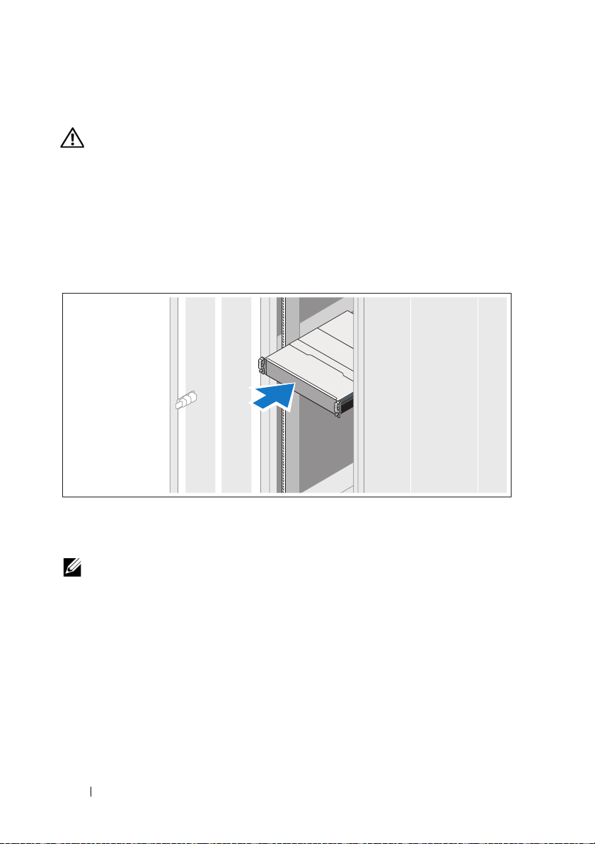
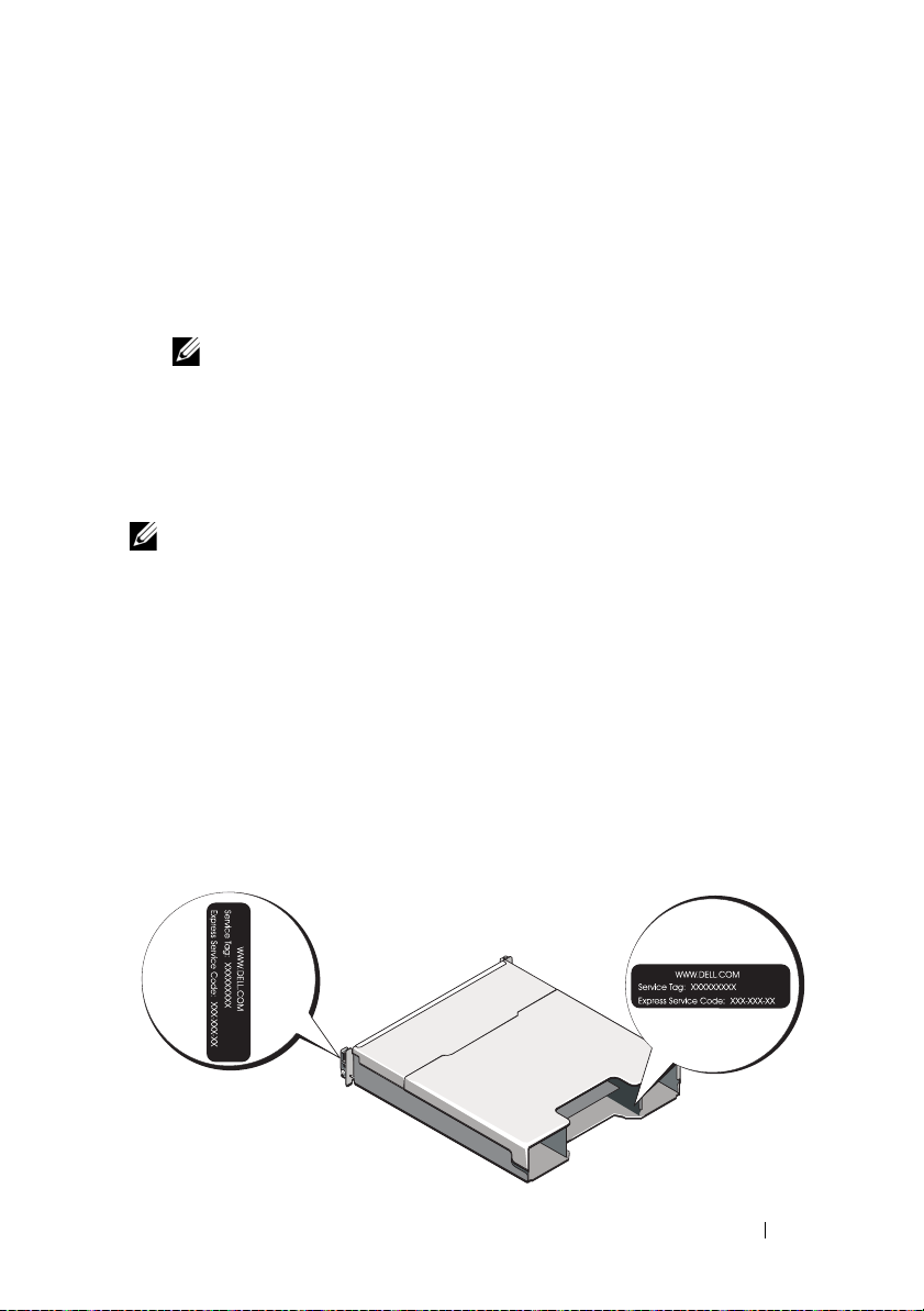
Installing the Rails and System in a Rack
Before performing the following procedure, review the safety
Assemble the rails and install the system in the rack following the safety
instructions and the rack installation instructions provided with your system.
NOTE:
To balance the weight load, it is recommended that you install the
PowerVault MD3200i series storage array at the bottom of the rack and the
PowerVault MD1200 series expansion enclosures above it.
10
Getting Started With Your System
Page 13
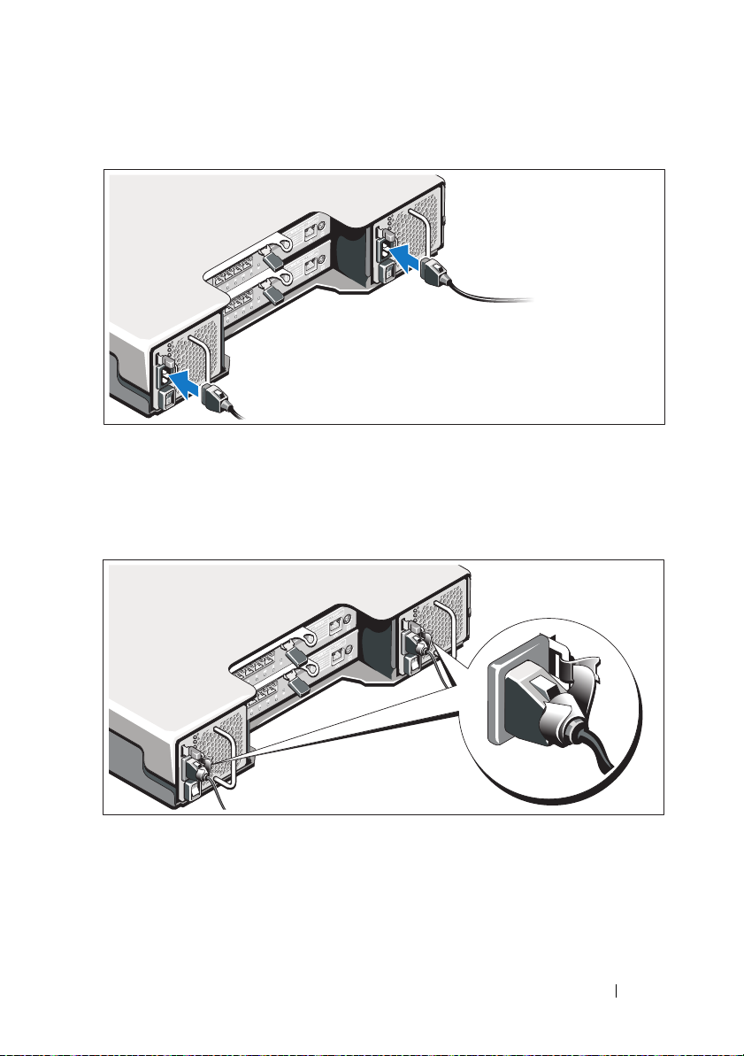
Connecting the Power Cable(s)
Ensure that the power switch is in the OFF position before connecting the
power cables. Connect the system’s power cable(s) to the system.
Securing the Power Cable(s)
Secure the cable(s) firmly to the bracket using the provided strap.
Plug the other end of the power cables into a grounded electrical outlet or
a separate power source such as an uninterrupted power supply (UPS) or
a power distribution unit (PDU). Each power supply must be connected to a
separate power circuit.
Getting Started With Your System
11
Page 14
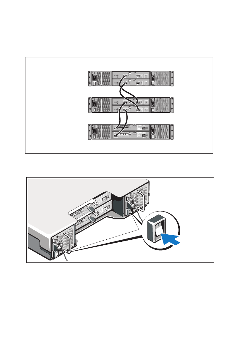
Cabling Your Expansion Enclosure
PowerVault MD3200i
series storage array
PowerVault MD1200
series expansion
enclosure 1 (optional)
PowerVault MD1200
series expansion
enclosure 2 (optional)
Turning On the Enclosure
12
Getting Started With Your System
Page 15
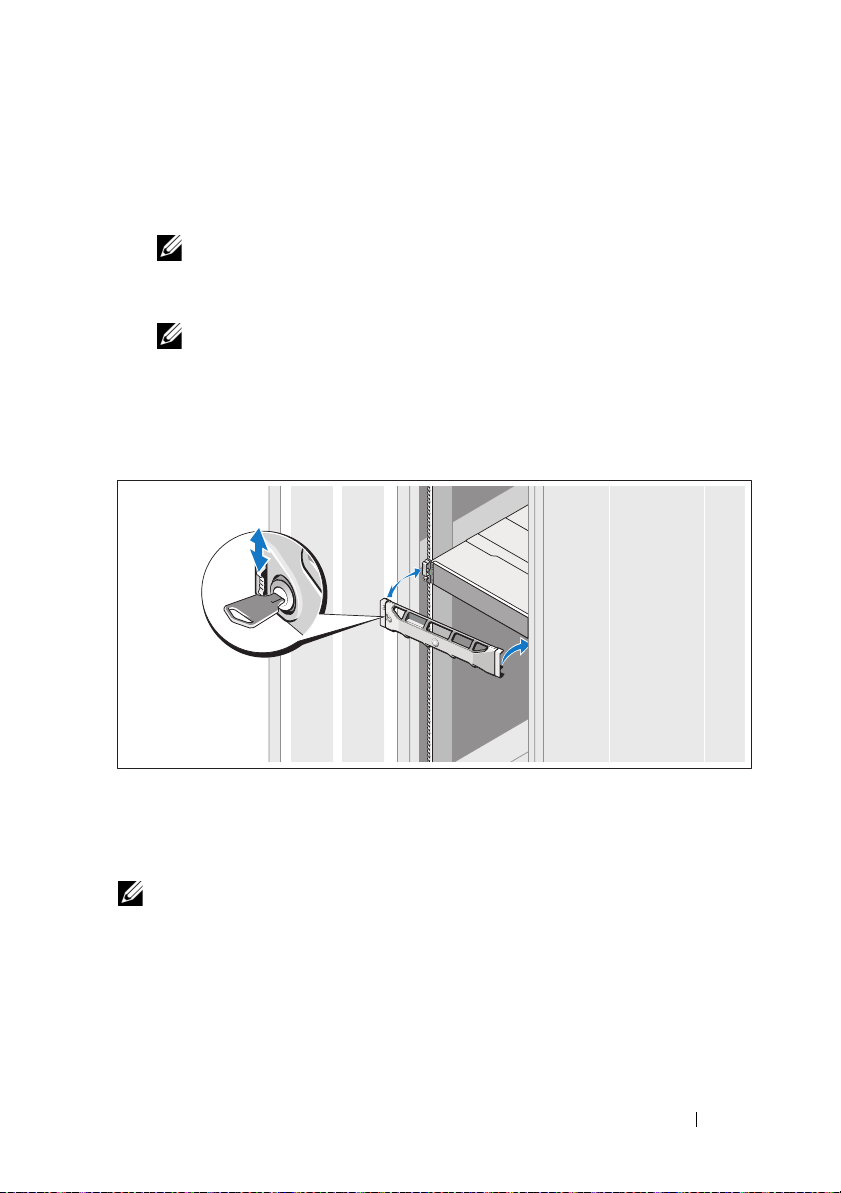
Turn on components in the following order
1
Ethernet switches (if used)
2
PowerVault MD1200 series expansion enclosures (if used)
NOTE:
Before turning on the storage array, ensure that the expansion
enclosure status LED is blue.
3
PowerVault MD3200i series storage array
NOTE:
Before turning on the host server(s), ensure that the storage array
status LED is blue.
4
Host server(s)
Installing the Bezel
Install the bezel (optional).
Installing the MD Storage Software
NOTE:
For detailed instructions about installing the MD storage software, setting
up the enclosure, and the post-installation tasks, see the Deployment Guide.
The MD Storage Manager software configures, manages and monitors the
storage array. The MD Configuration Utility (MDCU) is an optional utility
that provides a consolidated approach for configuring the management and
Getting Started With Your System
13
Page 16

iSCSI host ports, and creating sessions for the iSCSI modular disk storage
arrays. It is recommended that you use MDCU to configure iSCSI on each
host server connected to the storage array. To install the MD storage software:
1
Insert the MD series resource media.
Depending on your operating system, the installer may launch
automatically. If the installer does not launch automatically, navigate to
the root directory of the installation media (or downloaded installer
image) and run the
navigate to the root of the resource media and run the
NOTE:
By default, the Red Hat Enterprise Linux operating system mounts the
resource media with the -noexec mount option which does not allow you to
run executable files. To change this setting, see the Readme file in the root
directory of the installation media.
2
Select
Install MD Storage Software
3
Read and accept the license agreement.
4
Select one of the following installation options from the
md_launcher.exe
file. For Linux-based systems,
autorun
file.
.
Install Set
drop-
down menu:
•
Full (recommended)
— Installs the MD Storage Manager (client)
software, host-based storage agent, multipath driver, and hardware
providers.
•
Host Onl
y—Installs the host-based storage agent and multipath
drivers.
•
Management
—Installs the management software and hardware
providers.
•
Custom
5
Select the MD storage array model(s) you are setting up to serve as data
—Allows you to select specific components.
storage for this host server.
6
Choose whether to start the event monitor service automatically when the
host server reboots or manually
NOTE:
This option is applicable only to Windows client software installation.
7
Confirm the installation location and click
8
If prompted, reboot the host server after the installation completes.
14
Getting Started With Your System
Install
.
Page 17
9
When the reboot is complete, the MDCU may launch automatically. If
the MDCU does not launch automatically, launch it manually.
• In a Windows-based operating system, click
Disk Configuration Utility
.
• In a Linux-based operating system, double-click the
Configuration Utility
NOTE:
If MDCU is not installed, see the Deployment Guide at
support.dell.com/manuals.
10
Start the
11
If applicable, activate any premium features purchased with your storage
MD Storage Manager
icon on the desktop.
and discover the array(s).
Start→
Dell→
Modular
Modular Disk
array. If you purchased premium features, see the printed activation card
shipped with your storage array.
NOTE:
The MD Storage Manager installer automatically installs the required
drivers, firmware, and operating system patches/hotfixes to operate your storage
array. These drivers and firmware are also available at support.dell.com. In
addition, see the Support Matrix at support.dell.com/manuals for any additional
settings and/or software required for your specific storage array.
Locating Your Service Tag
Your system is identified by a unique Express Service Code and Service Tag
number. The Express Service Code and Service Tag are found on the front of
the system and at the back of the system next to the RAID controller
modules. This information is used by Dell to route support calls to the
appropriate personnel.
Getting Started With Your System
15
Page 18
NOM Information (Mexico Only)
The following information is provided on the device described
in this document in compliance with the requirements of the
official Mexican standards (NOM):
Importer:
Model number: E03J and E04J
Supply voltage: 100–240 V CA
Frequency: 50/60 Hz
Current consumption: 8.6 A
Technical Specifications
Drives
PowerVault MD3200i Up to twelve 3.5-inch SAS hot-swappable hard
drives (3.0 Gbps and 6.0 Gbps)
PowerVault MD3220i Up to twenty four 2.5-inch SAS hot-swappable hard
drives (3.0 Gbps and 6.0 Gbps)
RAID Controller Modules
RAID controller modules
Back-Panel Connectors (Per RAID Controller Module)
iSCSI connectors Four 1 GB iSCSI IN connectors to connect hosts
SAS expansion connector One SAS OUT port for expansion to an additional
Serial connector One 6-pin mini-DIN connector
16
Getting Started With Your System
• One or two hot-swappable modules
with temperature sensors
• 2 GB of cache per controller
PowerVault MD1200 series enclosure.
NOTE:
SAS connectors are SFF-8088 compliant.
NOTE:
For technical support use only.
Page 19

Back-Panel Connectors (Per RAID Controller Module) (continued)
Management Ethernet
connector
Expansion
PowerVault MD1200 series Supports a maximum of 192 hard drives with any
Backplane Board
Connectors
Sensors Two temperature sensors
One 100/1000 Base-T port Ethernet for out-of-band
management of the enclosure
NOTE:
The default management port IP addresses for
the primary and secondary RAID controller modules
are 192.168.128.101 and 192.168.128.102, respectively.
By default, the management ports are set to Dynamic
Host Configuration Protocol (DHCP). If the controller is
unable to get an IP address configuration from a DHCP
server within a specified time out period
(approximately 3 minutes), it defaults back to static IP
addressing. For more information, see the Deployment
Guide.
combination of PowerVault MD1200 or PowerVault
MD1220 expansion enclosures. Support for 192 hard
drives is a Premium Feature and requires activation.
The maximum number of hard drives supported
without using the Premium Feature is 120.
Redundant path connectivity provides redundant
data paths to each hard drive.
• 12 or 24 SAS hard-drive connectors
• Two power supply/cooling fan module connectors
• Two sets of RAID controller module connectors
• One control panel connector for front LEDs and
enclosure mode switch
Getting Started With Your System
17
Page 20

LED Indicators
Front panel
Hard-drive carrier
Power supply/cooling fan Three LED status indicators for power supply status,
RAID controller module Ten single-color LEDs:
• One two-color LED indicator for system status
• Two single-color LED indicators for power and
enclosure mode
NOTE:
The enclosure mode LED is not applicable to
the PowerVault MD3200i series storage array.
• One single-color activity LED
• One two-color LED status indicator per drive
power supply/fan fault, and AC status
• One battery fault
• One cache active
• One controller fault
• One controller power
• One system identification
• One management Ethernet activity
• Four iSCSI IN port activity
Six two-color LEDs:
• Four iSCSI IN link speed
• One SAS OUT link or fault
• One management Ethernet link speed
Switch
System identification button Located on the front control panel. This button is
used to locate a system within a rack.
Enclosure mode switch Located on the front of the system. This switch is
not applicable to the PowerVault MD3200i series
storage array.
Password reset switch Located on the back panel of the RAID controller
module. This switch is used to reset the storage array
password.
18
Getting Started With Your System
Page 21

Power Supplies
AC power supply (per power supply)
Wattage
Vo lt ag e
Heat dissipation
Maximum inrush current
Available Hard-Drive Power (Per Slot)
PowerVault MD3200i 25 W
PowerVault MD3220i 12 W
RAID Controller Module Power (Per Slot)
Maximum power consumption 100 W
Physical
PowerVault MD3200i
Height
Width
Depth
Weight (maximum
configuration)
Weigh t ( emp t y )
PowerVault MD3220i
Height
Width
Depth
Weight (maximum
configuration)
Weigh t ( emp t y )
600 W
100–240 VAC (8.6 A–4.3 A)
100 W
Under typical line conditions and over the entire
system ambient operating range, the inrush current
may reach a maximum of 55 A per power supply for
10 ms or less.
8.68 cm (3.41 inches)
44.63 cm (17.57 inches)
60.20 cm (23.70 inches)
29.30 kg (64.6 lb)
8.84 kg (19.5 lb)
8.68 cm (3.41 inches)
44.63 cm (17.57 inches)
54.90 cm (21.61 inches)
24.22 kg (53.4 lb)
8.61 kg (19lb)
Getting Started With Your System
19
Page 22

Environmental
NOTE:
For additional information about environmental measurements for specific
system configurations, see www.dell.com/environmental_datasheets.
Te mp e ra t u re
Operating
Storage
Relative humidity
Operating
Storage
Maximum vibration
Operating
Storage
Maximum shock
Operating
Storage
Altitude
Operating
Storage
Airborne Contaminant Level
Class
10 °C to 35 °C (50 °F to 95 °F) with a maximum
temperature gradation of 10 °C per hour
NOTE:
For altitudes above 2950 feet, the maximum
operating temperature is derated 1ºF/550 ft.
–40° to 65°C (–40° to 149°F) with a maximum
temperature gradation of 20°C per hour
20% to 80% (noncondensing) with a maximum
humidity gradation of 10% per hour
5% to 95% (noncondensing)
0.25 G at 3–200 Hz for 15 min
0.5 G at 3–200 Hz for 15 min
One shock pulse in the positive z axis (one pulse on
each side of the system) of 31 G for 2.6 ms in the
operational orientation
Six consecutively executed shock pulses in the
positive and negative x, y, and z axes (one pulse on
each side of the system) of 71 G for up to 2 ms
–16 to 3048 m (–50 to 10,000 ft)
NOTE:
For altitudes above 2950 feet, the maximum
operating temperature is derated 1ºF/550 ft.
–16 to 10,600 m (–50 to 35,000 ft)
G1 as defined by ISA-S71.04-1985
20
Getting Started With Your System
Page 23

Matrices de stockage
Dell PowerVault MD3200i
et MD3220i
Guide de mise en route
Séries E03J et E04J de modèle réglementaire
Page 24

Remarques, précautions et avertissements
REMARQUE :
vous aider à mieux utiliser votre ordinateur.
PRÉCAUTION :
matériel ou de perte de données en cas de non-respect des instructions.
AVERTISSEMENT:
du matériel, de blessure corporelle ou de mort.
____________________
Les informations que contient ce document sont sujettes à modification sans préavis.
© 2011 Dell Inc. Tous droits réservés.
La reproduction de ce document, de quelque manière que ce soit, sans l'autorisation écrite de Dell Inc.
est strictement interdite.
Marques utilisées dans ce document : Dell™, le logo DELL et PowerVault™ sont des marques de
Dell Inc. Microsoft
Corporation aux États-Unis et/ou dans d'autres pays. Red Hat
marques déposées de Red Hat, Inc. aux États-Unis et dans d'autres pays. SUSE
déposée de Novell, Inc. aux États-Unis et dans d'autres pays. VMware
VMware, Inc. aux États-Unis et/ou dans d'autres juridictions.
D'autres marques et noms commerciaux peuvent être utilisés dans ce document pour faire référence
aux entités revendiquant la propriété de ces marques ou de ces noms de produits. Dell Inc. rejette tout
intérêt exclusif dans les marques et les noms commerciaux autres que les siens.
une REMARQUE indique des informations importantes qui peuvent
une PRÉCAUTION vous avertit d'un risque d'endommagement du
un AVERTISSEMENT indique un risque d'endommagement
®
et Windows Server® sont des marques ou des marques déposées de Microsoft
®
et Red Hat Enterprise Linux® sont des
®
®
est une marque
est une marque déposée de
Séries E03J et E04J de modèle réglementaire
2011 - 08 N/P TFKD1 Rév. A02
Page 25

Avant de commencer
REMARQUE :
Dell PowerVault série MD3200i concernent les matrices de stockage
Dell PowerVault MD3200i et Dell PowerVault MD3220i. Le boîtier d'extension
Dell PowerVault MD1200 désigne les boîtiers Dell PowerVault MD1200 et
Dell PowerVault MD1220.
Avant d'installer votre matrice de stockage Dell PowerVault série MD3200i,
vous devez considérer certaines des meilleures pratiques pour assurer le
fonctionnement le plus efficace possible de votre matrice de stockage et une
redondance complète (si nécessaire).
• Il vous est recommandé d'utiliser un IP SAN dédié pour la transmission
des données iSCSI. La gestion de trafic peut être isolée sur un réseau de
gestion distinct.
• Renseignez la liste de vérification de la configuration de l'interface iSCSI
avant de configurer iSCSI. Voir « Compléter la liste de vérification de
l'interface iSCSI. », à la page 24. Cette liste permet de regrouper les
informations de réseaux physiques en un seul endroit.
• Esquissez la configuration après avoir complété la liste de vérification
iSCSI et avant de définir la solution.
• Configurez toujours des chemins d'accès aux données redondants de
manière à fournir différents chemins d'accès allant au serveur hôte et en
sortant, dans l'éventualité d'une défaillance de l'un d'eux.
• Si plusieurs cartes réseau sont installées sur un hôte, il vous est
recommandé d'utiliser plusieurs sous-réseaux pour la gestion et les liaisons
de données iSCSI.
• Utilisez toujours un câble Ethernet de catégorie 5e (ou plus) à travers
le réseau.
• Avant de connecter tout câble entre le serveur hôte et la matrice de
stockage, étiquetez physiquement chaque port et chaque connecteur.
• Suivez toujours les procédures de mise sous et hors tension lors des
cycles d'alimentation du réseau. Vous devez également vous assurer
que les composants essentiels du réseau se trouvent sur différents
circuits d'alimentation.
REMARQUE :
câblage d'une seule matrice de stockage PowerVault série MD3200i dans un
environnement de réseau SAN. Elles ne montrent également que les adresses IP
par défaut de la matrice de stockage PowerVault série MD3200i. Pour câbler plus
d'une matrice de stockage PowerVault série MD3200i dans un environnement de
réseau SAN, voir le Guide de déploiement.
Dans ce document, les références à la matrice de stockage
les illustrations qui figurent dans ce document montrent aussi le
Guide de mise en route
23
Page 26
Compléter la liste de vérification de
Clé secrète
CHAP mutuelle
Clé secrète
CHAP cible
A
B
serveur hôte
Matrice de
stockage
PowerVault série
MD3200i
192.168.130.101 (entrée 0 par défaut)
192.168.131.101 (ent. 1 par défaut)
192.168.132.101 (entrée 2 par défaut)
192.168.133.101 (ent. 3 par défaut)
192.168.128.101 (port du réseau de gestion)
192.168.130.102 (ent. 0 par défaut)
192.168.131.102 (entrée 1 par défaut)
192.168.132.102 (ent. 2 par défaut)
192.168.133.102 (entrée 3 par défaut)
192.168.128.102 (port réseau de gestion)
Au besoin, utilisez une feuille supplémentaire (si vous disposez de plusieurs serveurs hôtes,
par exemple).
Port iSCSI 1
Port iSCSI 2
Port iSCSI 3
Port iSCSI 4
Port de gestion
Adresse IP statique (serveur hôte)
Masque de
sous-réseau
Passerelle par défaut
A
___ ___ ___ ___
___ ___ ___ ___
___ ___ ___ ___
___ ___ ___ ___
___ ___ ___ ___
___ ___ ___ ___
___ ___ ___ ___
___ ___ ___ ___
___ ___ ___ ___
___ ___ ___ ___
___ ___ ___ ___
___ ___ ___ ___
___ ___ ___ ___
___ ___ ___ ___
___ ___ ___ ___
REMARQUE :
le serveur hôte peut prendre en charge jusqu'à quatre cartes réseau
l'interface iSCSI.
Paramètres IPv4
24
Guide de mise en route
Page 27
Adresse IP statique (m. de stockage)
Masque de
sous-réseau
Passerelle par
défaut
B
___ ___ ___ ___
___ ___ ___ ___
___ ___ ___ ___
___ ___ ___ ___
___ ___ ___ ___
___ ___ ___ ___
___ ___ ___ ___
___ ___ ___ ___
___ ___ ___ ___
___ ___ ___ ___
Contrôleur iSCSI 0, Ent. 0
Contrôleur iSCSI 0, Ent. 1
Contrôleur iSCSI 0, Ent. 2
Contrôleur iSCSI 0, Ent. 3
Port de gestion cntrl 0
Contrôleur iSCSI 1, Ent. 0
Contrôleur iSCSI 1, Ent. 1
Contrôleur iSCSI 1, Ent. 2
Contrôleur iSCSI 1, Ent. 3
Port de gestion cntrl 1
___ ___ ___ ___
___ ___ ___ ___
___ ___ ___ ___
___ ___ ___ ___
___ ___ ___ ___
___ ___ ___ ___
___ ___ ___ ___
___ ___ ___ ___
___ ___ ___ ___
___ ___ ___ ___
___ ___ ___ ___
___ ___ ___ ___
___ ___ ___ ___
___ ___ ___ ___
___ ___ ___ ___
___ ___ ___ ___
___ ___ ___ ___
___ ___ ___ ___
___ ___ ___ ___
___ ___ ___ ___
REMARQUE :
de déploiement.
Autre documentation et support dont vous pourriez avoir besoin
AVERTISSEMENT :
réglementations qui accompagnent votre système. Les informations sur la garantie
se trouvent dans ce document ou dans un document distinct.
REMARQUE :
le site support.dell.com/manuals.
• La documentation fournie avec le rack indique comment installer le
système dans un rack.
•Le
Manuel du propriétaire du matériel
caractéristiques du système, ainsi que des instructions relatives au
dépannage et à l'installation ou au remplacement de composants.
•Le
Guide de déploiement
configuration du logiciel et du matériel.
•Le
Guide CLI
de commande (CLI) pour configurer et gérer votre matrice de stockage.
pour plus d'informations sur la liste de vérification IPv6, voir le Guide
tous les documents PowerVault série MD3200i sont disponibles sur
fournit des informations sur l'utilisation de l'interface de ligne
reportez-vous aux informations sur la sécurité et les
fournit des informations sur l'installation et la
contient des informations sur les
Guide de mise en route
25
Page 28
•Le
Guide de programmation SMI-S
fournit des informations sur
l'utilisation du fournisseur MI-S et la programmation SMI-S.
• Tous les supports fournis avec le système contiennent de la documentation et
des outils de configuration et de gestion du système, notamment du système
d'exploitation même et du logiciel de gestion du système ; les supports
contiennent également des mises à jour et les composants système que vous
avez achetés avec le système.
REMARQUE :
support.dell.com/manuals et lisez-les en premier, car elles remplacent
souvent les informations que contiennent les autres documents.
vérifiez toujours si des mises à jour sont disponibles sur le site
Préparation du serveur hôte
Systèmes d'exploitation pris en charge
• Microsoft Windows Server
• Red Hat Enterprise Linux
• SUSE Linux Enterprise Server
• VMware
REMARQUE :
système d'exploitation prises en charge, reportez-vous à la Matrice de support sur
support.dell.com/manuals.
Cartes réseau supplémentaires pour l'interface iSCSI
Lors de l'installation de cartes réseau supplémentaires, il vous est
recommandé de :
• Utiliser des réseaux de stockage redondants dédiés pour le trafic iSCSI.
Isoler le trafic iSCSI du trafic de réseau général à l'aide du réseau local
virtuel (VLAN) si un réseau dédié n'est pas disponible.
• Utiliser des cartes réseau dédiées supplémentaires pour le trafic iSCSI.
• Les cartes réseau doivent être ajoutées en paires (jusqu'à quatre
cartes réseau).
REMARQUE :
pour les informations les plus récentes sur toutes les versions de
une carte réseau seule est également prise en charge.
Configuration de carte réseau
Dans un environnement de réseau SAN, selon le nombre de commutateurs, il
vous est recommandé d'utiliser deux ou quatre sous-réseaux uniques pour le
trafic iSCSI. Dans les environnements de stockage reliés directement, chaque
carte réseau en connexion directe avec la matrice de stockage série MD3200i
doit se trouver sur un sous-réseau différent.
26
Guide de mise en route
Page 29

Configurations courantes
Serveur 1 Serveur 2
Matrice de
stockage
Serveur 3 Serveur 4
Réseau
d'entreprise, public
ou privé
Câblage des hôtes reliés directement
Guide de mise en route
27
Page 30

Câblage des hôtes reliés au réseau SAN
Matrice de
stockage
Réseau
d'entreprise, public
ou privé
Commutateur 1 Commutateur 2
Serveur
28
Guide de mise en route
Page 31

Jusqu'à 32 hôtes
Serveur 1 Serveur 2
Matrice de
stockage
Réseau
d'entreprise, public
ou privé
Commutateur 1 Commutateur 2
Guide de mise en route
29
Page 32

Installation et configuration
AVERTISSEMENT:
consignes de sécurité fournies avec le système.
Déballage du système
Déballez votre système et identifiez chaque élément en consultant la liste de
composants livrée avec votre système.
Installation des rails et du système dans un rack
avant d'exécuter la procédure ci-dessous, lisez les
Assemblez les rails et installez le système dans le rack en suivant les consignes
de sécurité et les instructions d'installation du rack fournies avec votre système.
REMARQUE :
matrice de stockage PowerVault série MD3200i en bas du rack et les boîtiers
d'extension PowerVault série MD1200 au-dessus.
30
Guide de mise en route
pour équilibrer la charge, nous vous recommandons d'installer la
Page 33

Branchement du ou des câbles d'alimentation
Avant de connecter les câbles d'alimentation, assurez-vous que le
commutateur d'alimentation est en position OFF (ÉTEINT). Branchez le ou
les câbles d'alimentation sur le système.
Fixation du ou des câbles d'alimentation
Fixez fermement les câbles au support de fixation à l'aide de la lanière fournie.
Branchez ensuite l'autre extrémité des câbles d'alimentation sur une prise de
courant mise à la masse ou sur une source d'alimentation autonome (onduleur
[UPS] ou unité de distribution de l'alimentation [PDU]...). Chaque bloc
d'alimentation doit être connecté à un circuit d'alimentation différent.
Guide de mise en route
31
Page 34

Câblage de votre boîtier d'extension
Matrice de stockage
PowerVault série
MD3200i
Boîtier d'extension
PowerVault série
MD1200 1 (en option)
Boîtier d'extension
PowerVault série
MD1200 2 (en option)
Mise sous tension du boîtier
32
Guide de mise en route
Page 35

Mettez les composants sous tension dans l'ordre suivant
1
Commutateurs Ethernet (si utilisés).
2
Boîtiers d'extension PowerVault série MD1200 (si utilisés).
REMARQUE :
voyant d'état du boîtier d'extension est bleu.
3
Matrice de stockage PowerVault série MD3200i.
REMARQUE :
voyant d'état de la matrice de stockage est bleu.
4
Serveur(s) hôte.
avant d'allumer la matrice de stockage, assurez-vous que le
avant d'allumer le(s) serveur(s) hôte, assurez-vous que le
Installation du cadre
Installez le cadre (en option).
Installation du logiciel MD Storage
REMARQUE :
de stockage MD, la configuration du boîtier et les tâches après installation, voir le
Guide de déploiement.
pour des instructions détaillées concernant l'installation du logiciel
Guide de mise en route
33
Page 36

L'application MD Storage Manager configure, gère, et contrôle la matrice de
stockage. L'utilitaire de configuration MD (MDCU) est un utilitaire
optionnel qui permet une approche consolidée de la configuration des ports
de gestion, des ports hôtes iSCSI et de la création de sessions pour les
matrices de stockage sur disques modulaires iSCSI. Il vous est recommandé
d'utiliser l'utilitaire MDCU pour configurer iSCSI sur chaque hôte connecté à
la matrice de stockage. Pour installer le logiciel MD Storage Manager :
1
Insérez le support Ressource série MD.
En fonction de votre système d'exploitation, l'installateur se lancera peut-
être automatiquement. Si l'installateur ne se lance pas automatiquement,
naviguez dans le répertoire racine du support d'installation (ou téléchargez
l'image d'installateur) et exécutez le fichier
md_launcher.exe
. Pour les
systèmes exécutant Linux, naviguez vers la racine du support Ressource et
exécutez le fichier
REMARQUE :
(RHEL) monte le support Ressource à l'aide de l'option de montage –noexec
mount, qui ne vous permet pas d'exécuter les fichiers exécutables. Pour
modifier ce paramètre, consultez le fichier Lisez-moi dans le répertoire racine
du support d'installation.
2
Sélectionnez
autorun
par défaut, le système d'exploitation Red Hat Enterprise Linux
Install MD Storage Software
(Exécution auto).
(Installer le logiciel de
stockage MD).
3
Lisez le contrat de licence et acceptez-le.
4
Sélectionnez l'une des options d'installation suivantes dans le menu
déroulant
•
Install Set
Full (recommended)
(Configuration d'installation) :
(Complète - recommandée) : installe le logiciel
(client) MD Storage Manager, l'agent de stockage hôte, le pilote
multivoies, et les fournisseurs de matériel.
Host Only
•
(Hôte uniquement) : installe l'agent de stockage hôte et les
pilotes multivoies.
Management
•
(Gestion) : installe le logiciel de gestion et les
fournisseurs de matériel.
• Custom (Personnalisée) : permet de sélectionner des
composants spécifiques.
Sélectionnez le(s) modèle(s) de matrice de stockage MD que vous
5
souhaitez définir comme stockage de données pour ce serveur hôte.
6
Choisissez de démarrer le service de moniteur des événements
automatiquement lors du redémarrage du serveur hôte ou manuellement
34
Guide de mise en route
Page 37

REMARQUE :
client Windows.
7
Confirmez l'emplacement de l'installation et cliquez sur
cette option ne s'applique qu'à l'installation du logiciel
Install
(Installer).
8 À l'invitation (le cas échéant), redémarrez le serveur hôte après la fin
de l'installation.
9 Lorsque le redémarrage est terminé, l'utilitaire MDCU peut se
lancer automatiquement. S'il ne se lance pas automatiquement,
lancez-le manuellement.
• Dans un système d'exploitation Windows, cliquez sur
Démarrer→
Dell→
Modular Disk Configuration Utility
(Utilitaire
de configuration de disques modulaires).
• Dans un système d'exploitation Linux, double-cliquez sur l'icône
Modular Disk Configuration Utility
(Utilitaire de configuration de
disques modulaires) sur le bureau.
REMARQUE :
déploiement à l'adresse support.dell.com/manuals.
10
Démarrez
11
Le cas échéant, activez les fonctions premium achetées avec votre matrice
MD Storage Manager
si l'utilitaire MDCU n'est pas installé, voir le Guide de
et lancez la détection des matrices.
de stockage. Si vous avez acheté des fonctions premium, consultez la carte
d'activation livrée avec votre matrice de stockage.
REMARQUE :
pilotes, micrologiciel, et correctifs de système d'exploitation nécessaires au
fonctionnement de votre matrice de stockage. Ces pilotes et micrologiciels sont
également disponibles à l'adresse support.dell.com. Consultez également la
Matrice de prise en charge à l'adresse support.dell.com/manuals pour connaître
les paramètres et/ou logiciels supplémentaires requis pour votre matrice de
stockage particulière.
l'installateur MD Storage Manager installe automatiquement les
Guide de mise en route
35
Page 38

Identification du numéro de service
Votre système est identifié par un code de service express et un numéro de
service uniques. Le code de service express et le numéro de service se trouvent
sur le devant et l'arrière du système à côté des modules de contrôleur RAID.
Dell utilise ces informations pour acheminer les appels de support au
technicien qui convient.
Informations NOM (Mexique uniquement)
Les informations suivantes sur l'appareil décrit dans ce document sont fournies
conformément aux exigences de la Norme Officielle Mexicaine (NOM) :
Importateur : Dell Inc. de México, S.A. de C.V.
Paseo de la Reforma 2620 - 11° Piso
Col. Lomas Altas
11950 México, D.F.
Numéro de modèle : E03J et E04J
Tension
d'alimentation :
Fréquence : 50/60 Hz
Consommation
électrique :
100 à 240 V CA
8,6 A
36
Guide de mise en route
Page 39

Caractéristiques techniques
Lecteurs
PowerVault MD3200i Jusqu'à 12 disques durs SAS remplaçables à chaud
3,5 pouces (3,0 Gb/s et 6,0 Gb/s)
PowerVault MD3220i Jusqu'à 24 disques durs SAS remplaçables à chaud
2,5 pouces (3,0 Gb/s et 6,0 Gb/s)
Modules de contrôleur RAID
Modules de contrôleur RAID
Connecteurs du panneau arrière (par module de contrôleur RAID)
Connecteurs iSCSI Quatre connecteurs d'entrée iSCSI de 1 Go pour
Connecteur d'extension SAS Un port de sortie SAS pour l'extension à un boîtier
Connecteur série Un connecteur mini-DIN à 6 broches
Connecteur Ethernet
de gestion
• Un ou deux modules remplaçables à chaud avec
capteurs de température.
• 2 Go de mémoire cache par contrôleur
connecter les hôtes
PowerVault série MD1200 supplémentaire.
REMARQUE :
conformes SFF-8088
REMARQUE :
de maintenance.
Un port Ethernet 100/1000 Base-T pour une gestion
hors bande du boîtier
REMARQUE :
défaut des modules de contrôleur RAID primaire et
secondaire sont respectivement192.168.128.101 et
192.168.128.102. Par défaut, les ports de gestion sont
définis sur le protocole DHCP (Dynamic Host
Configuration). Si le contrôleur ne parvient pas à obtenir
une configuration d'adresse IP d'un serveur DHCP au
cours d'une période de temps donnée (environ 3
minutes), par défaut il utilise l'adressage IP statique.
Pour plus d'informations, voir le
les connecteurs SAS sont
cette option est réservée au personnel
les adresses IP de port de gestion par
Guide de déploiement
.
Guide de mise en route
37
Page 40

Extension
PowerVault Série MD1200 Prend en charge jusqu'à 192 disques durs avec
n'importe quelle combinaison de boîtiers
d'extension PowerVault MD1200 ou PowerVault
MD1220. La prise en charge de 192 disques durs est
une fonction premium et doit être activée. Le
nombre maximum de disques durs pris en charge
sans utiliser la fonction premium est 120.
La connectivité à chemin redondant fournit des
chemins de données redondants à chaque disque dur.
Carte de fond de panier
Connecteurs
Capteurs Deux capteurs de température
Voyants
Panneau avant
Support de disque dur
Bloc d'alimentation/ventilateur
de refroidissement
• 12 ou 24 connecteurs de disque dur SAS
• Deux connecteurs pour les modules de
ventilation/alimentation
• Deux ensembles de connecteurs de module de
contrôleur RAID
• Un connecteur de panneau de commande pour
les voyants frontaux et le commutateur de
mode boîtier
• Un voyant bicolore indiquant l'état du système
• Deux voyants monochromes (alimentation et
mode boîtier)
REMARQUE :
pas à la matrice de stockage
PowerVault série MD3200i.
• Un voyant d'activité monochrome
• Un voyant d'état bichrome par lecteur
Trois voyants d'état (état du bloc d'alimentation,
panne du bloc d'alimentation/ventilateur et état
de l'alimentation)
le voyant du mode boîtier ne s'applique
38
Guide de mise en route
Page 41

Voyants (suite)
Module de contrôleur RAID Dix voyants monochromes :
• Un voyant de panne de batterie
• Un voyant d'activité de la mémoire cache
• Un voyant de panne du contrôleur
• Un voyant d'état de l'alimentation de contrôleur
• Un voyant système
• Un voyant d'activité de gestion Ethernet
• Quatre voyants d'activité de port d'entrée iSCSI
Six voyants bichromes :
• Quatre voyants de vitesse de lien d'entrée iSCSI
• Un voyant de panne ou de lien de sortie SAS
• Un voyant de vitesse de lien Ethernet de gestion
Commutateur
Bouton d'identification du
système
Sélecteur de mode Boîtier Situé sur le devant du système. Ce sélecteur
Sélecteur de réinitialisation du
mot de passe
Situé sur le panneau de commande avant. Ce
bouton sert à localiser un système au sein d'un rack.
ne s'applique pas à la matrice de stockage
PowerVault série MD3200i.
Situé sur le panneau arrière du module de contrôleur
RAID. Ce sélecteur permet de réinitialiser le mot de
passe de la matrice de stockage.
Blocs d'alimentation
Alimentation secteur (par bloc d'alimentation)
Puissance
Te ns i on
Dissipation thermique
Courant d'appel maximal
600 W
100–240 VCA (8,6 A–4,3 A)
100 W
Dans des conditions de ligne typiques et dans toute
la gamme ambiante de fonctionnement du système,
l'appel de courant peut atteindre 55 A par bloc
d'alimentation pendant un maximum de 10 ms.
Guide de mise en route
39
Page 42

Alimentation disponible pour les disques durs (par logement)
PowerVault MD3200i 25 W
PowerVault MD3220i 12 W
Alimentation du module de contrôleur RAID (par emplacement)
Consommation de courant
maximale
Caractéristiques physiques
PowerVault MD3200i
Hauteur
Largeur
Profondeur
Poids (configuration maximale)
Poids (vide)
PowerVault MD3220i
Hauteur
Largeur
Profondeur
Poids (configuration maximale)
Poids (vide)
100 W
8,68 cm (3,41 pouces)
44,63 cm (17,57 pouces)
60,20 cm (23,70 pouces)
29,30 kg (64,6 livres)
8,84 kg (19,5 livres)
8,68 cm (3,41 pouces)
44,63 cm (17,57 pouces)
54,90 cm (21,61 pouces)
24,22 kg (53,4 livres)
8,61 kg (19 livres)
Environnement
REMARQUE :
environnementales liées aux différentes configurations du système, voir
www.dell.com/environmental_datasheets.
Température
En fonctionnement
Entreposage
40
pour des informations supplémentaires sur les mesures
De 10 à 35 °C (50 à 95 °F) avec un gradient
thermique maximal de 10 °C par heure
REMARQUE :
900 mètres (2 950 pieds), la température maximale de
fonctionnement est réduite de 0,55 °C (1 °F) tous les
168 mètres (550 pieds).
De -40 à 65 °C (-40 à 149 °F) avec un gradient
thermique maximal de 20 °C par heure
Guide de mise en route
pour les altitudes supérieures à
Page 43

Environnement (suite)
Humidité relative
En fonctionnement
Entreposage
Tolérance maximale aux vibrations
En fonctionnement
Entreposage
Choc maximal
En fonctionnement
Entreposage
Altitude
En fonctionnement
De 20 à 80 % (sans condensation) avec un gradient
d'humidité maximal de 10 % par heure
De 5 à 95 % (sans condensation)
0,25 G avec un balayage de 3 à 200 Hz pendant
15 minutes
0,5 G avec un balayage de 3 à 200 Hz pendant
15 minutes
Une impulsion de choc de 31 G pendant un
maximum de 2,6 ms sur l'axe z positif (une
impulsion de chaque côté du système)
Six chocs consécutifs de 71 G pendant un maximum
de 2 ms en positif et négatif sur les axes x, y et z (une
impulsion de chaque côté du système)
De -16 à 3 048 m (-50 à 10 000 pieds)
REMARQUE :
900 mètres (2 950 pieds), la température maximale de
fonctionnement est réduite de 0,55 °C (1 °F) tous les
168 mètres (550 pieds).
Entreposage
Contaminants en suspension dans l'air
Classe
De -16 à 10 600 m (-50 à 35 000 pieds)
G1 selon la norme ISA-S71.04-1985
Pour les altitudes supérieures à
Guide de mise en route
41
Page 44

42
Guide de mise en route
Page 45

Matrizes de armazenamento
Dell PowerVault MD3200i
e MD3220i
Introdução ao uso
do sistema
Modelo de normalização séries E03J e E04J
Page 46

Notas, Avisos e Advertências
NOTA:
uma NOTA fornece informações importantes para ajudar você a aproveitar
melhor os recursos do computador.
AVISO:
um AVISO indica um potencial de danos ao hardware ou a perda de dados
se as instruções não forem seguidas.
ADVERTÊNCIA:
risco de lesões corporais ou mesmo de risco de vida.
____________________
As informações contidas nesta publicação estão sujeitas a alterações sem aviso prévio.
© 2011 Dell Inc. Todos os direitos reservados.
Qualquer forma de reprodução deste material sem a permissão por escrito da Dell Inc. é
expressamente proibida.
Marcas comerciais usadas neste texto: Dell™, o logotipo DELL e PowerV ault™ são marcas comerciais
da Dell Inc.; Microsoft
Corporation nos Estados Unidos e em outros países. Red Hat
registradas da Red Hat, Inc. nos Estados Unidos e em outros países. SUSE
Novell, Inc. nos Estados Unidos e em outros países. VMware
nos Estados Unidos e/ou em outras jurisdições.
Outras marcas e nomes comerciais podem ser usados nesta publicação como referência às entidades
que reivindicam essas marcas e nomes ou a seus produtos. A Dell Inc. declara que não tem interesse
de propriedade sobre marcas comerciais e nomes de terceiros.
uma ADVERTÊNCIA indica um potencial de danos à propriedade,
®
e Windows Server® são marcas comerciais ou marcas registradas da Microsoft
®
e Red Hat Enterprise Linux® são marcas
®
é marca registrada da VMware, Inc.
®
é marca registrada da
Modelo de normalização séries E03J e E04J
Agosto de 2011 N/P TFKD1 Rev. A02
Page 47

Antes de começar
NOTA:
Neste documento, a matriz de armazenamento Dell PowerVault
série MD3200i se refere tanto à matriz Dell PowerVault MD3200i quanto à matriz
Dell PowerVault MD3220i. O gabinete de expansão Dell PowerVault série MD1200
se refere tanto ao Dell PowerVault MD1200 quanto ao Dell PowerVault MD1220.
Antes de configurar a matriz de armazenamento Dell PowerVault série MD3200i,
você precisa considerar certas práticas recomendadas que garantem que a sua
matriz de armazenamento funcione com a máxima eficiência e ofereça
redundância total (se necessário).
• É recomendável que você use uma SAN de IP dedicado para a transmissão
de dados iSCSI. O gerenciamento de tráfego pode ser isolado em uma rede
de gerenciamento separada.
• Preencha a planilha de configuração iSCSI antes de configurar o iSCSI.
Consulte “Preencher a planilha iSCSI” na página 46. Esta planilha reúne
informações da rede física em uma única fonte.
• Depois de preencher a planilha iSCSI, faça um desenho da configuração
antes de configurar a solução.
• Configure sempre caminhos redundantes de dados iSCSI para fornecer
caminhos alternativos de e para o servidor host, na eventualidade de um
destes caminhos se tornar indisponível.
• Se houver múltiplas placas de rede instaladas em um host, recomenda-se
que você use diferentes sub-redes para gerenciamento e para links de
dados iSCSI.
• Use sempre cabos de rede Ethernet Categoria 5e (ou melhores) em toda
a rede.
• Antes de conectar quaisquer cabos entre o servidor host e a matriz de
armazenamento, coloque uma etiqueta em cada porta e em cada conector.
• Siga sempre os procedimentos adequados para fazer o “power cycle”
(desligar e religar em seguida) de dispositivos da rede. Você precisa garantir
também que os componentes críticos da rede estejam em circuitos de
alimentação separados.
NOTA:
As ilustrações deste documento mostram o cabeamento de apenas uma
matriz de armazenamento PowerVault série MD3200i em um ambiente SAN. As
ilustrações mostram também apenas os endereços IP padrão da matriz de
armazenamento PowerVault série MD3200i. Para fazer o cabeamento de mais de
uma matriz de armazenamento PowerVault série MD3200i em um ambiente SAN,
consulte o guia de implementação.
Introdução ao Uso do Sistema
45
Page 48

Preencher a planilha iSCSI
Segredo CHAP
do destino
Segredo
CHAP mútuo
A
B
servidor host
Matriz de
armazenamento
PowerVault série
MD3200i
192.168.130.101 (em 0 por padrão)
192.168.131.101 (em 1 por padrão)
192.168.132.101 (em 2 por padrão)
192.168.133.101 (em 3 por padrão)
192.168.128.101 (porta da rede de gerenciamento)
192.168.130.102 (em 0 por padrão)
192.168.131.102 (em 1 por padrão)
192.168.132.102 (em 2 por padrão)
192.168.133.102 (em 3 por padrão)
192.168.128.102 (porta da rede de gerenciamento)
Se você precisar de espaço adicional para mais de um servidor host, use uma folha adicional.
Porta iSCSI 1
Porta iSCSI 2
Porta iSCSI 3
Porta iSCSI 4
Porta de
gerenciamento
Endereço IP estático (servidor host)
Máscara de sub-rede
Gateway padrão
A
___ . ___ . ___ . ___
___ . ___ . ___ . ___
___ . ___ . ___ . ___
___ . ___ . ___ . ___
___ . ___ . ___ . ___
___ . ___ . ___ . ___
___ . ___ . ___ . ___
___ . ___ . ___ . ___
___ . ___ . ___ . ___
___ . ___ . ___ . ___
___ . ___ . ___ . ___
___ . ___ . ___ . ___
___ . ___ . ___ . ___
___ . ___ . ___ . ___
___ . ___ . ___ . ___
NOTA:
O servidor host pode suportar até quatro placas de rede.
Configurações de IPv4
46
Introdução ao Uso do Sistema
Page 49

Endereço IP estático (matriz
de armazenamento)
Máscara de sub-rede
Gateway padrão
B
___ . ___ . ___ . ___
___ . ___ . ___ . ___
___ . ___ . ___ . ___
___ . ___ . ___ . ___
___ . ___ . ___ . ___
___ . ___ . ___ . ___
___ . ___ . ___ . ___
___ . ___ . ___ . ___
___ . ___ . ___ . ___
___ . ___ . ___ . ___
controlador iSCSI 0, em 0
controlador iSCSI 0, em 1
controlador iSCSI 0, em 2
controlador iSCSI 0, em 3
controlador da porta de
gerenciamento 0
controlador iSCSI 1, em 0
controlador iSCSI 1, em 1
controlador iSCSI 1, em 2
controlador iSCSI 1, em 3
controlador da porta de
gerenciamento 1
___ . ___ . ___ . ___
___ . ___ . ___ . ___
___ . ___ . ___ . ___
___ . ___ . ___ . ___
___ . ___ . ___ . ___
___ . ___ . ___ . ___
___ . ___ . ___ . ___
___ . ___ . ___ . ___
___ . ___ . ___ . ___
___ . ___ . ___ . ___
___ . ___ . ___ . ___
___ . ___ . ___ . ___
___ . ___ . ___ . ___
___ . ___ . ___ . ___
___ . ___ . ___ . ___
___ . ___ . ___ . ___
___ . ___ . ___ . ___
___ . ___ . ___ . ___
___ . ___ . ___ . ___
___ . ___ . ___ . ___
Outros documentos e mídias dos quais você pode precisar
• A documentação fornecida com o rack contém o procedimento de
•O
•O
•O
NOTA:
Para obter informações sobre a planilha de IPv6, consulte o guia de
implementação.
ADVERTÊNCIA:
Consulte as informações de normalização e segurança
fornecidas com o sistema. As informações de garantia podem estar neste
documento ou podem ser fornecidas como um documento separado.
NOTA:
Todos os documentos da matriz de armazenamento PowerVault série
MD3200i estão disponíveis em support.dell.com/manuals.
instalação do sistema no rack.
Manual do proprietário
sistema e descreve como solucionar problemas do sistema e como instalar
ou trocar componentes.
Guia de implementação
configuração do software e do hardware.
Guia da Interface de Linha de Comando (CLI)
sobre o uso da interface de linha de comando para configurar e gerenciar
a matriz de armazenamento.
fornece informações sobre os recursos do
fornece informações sobre a instalação e a
Introdução ao Uso do Sistema
fornece informações
47
Page 50

•O
Guia do programador de SMI-S
fornece informações sobre o uso do
provedor de SMI-S e sobre a programação de SMI-S.
• As mídias fornecidas com o sistema que contêm documentação e ferramentas
para a configuração e o gerenciamento do sistema, incluindo aquelas
relacionadas ao sistema operacional, ao software de gerenciamento do sistema,
a atualizações do sistema e a componentes adquiridos com o sistema.
NOTA:
Verifique sempre se há atualizações disponíveis no site
support.dell.com/manuals (em inglês) e leia primeiro as atualizações, pois
estas geralmente substituem informações contidas em outros documentos.
Preparar o servidor host
Sistemas operacionais suportados
• Microsoft Windows Server
• Red Hat Enterprise Linux
• SUSE Linux Enterprise Server
• VMware
NOTA:
Para obter as informações mais recentes sobre todas as versões de
sistemas operacionais suportadas, consulte Support Matrix (Matriz de suporte) no
site support.dell.com/manuals.
Placas de rede adicionais para iSCSI
Quando for instalar placas de rede adicionais, é recomendável que:
• Você use redes de armazenamento redundante dedicadas para tráfego
iSCSI. Se não for possível ter uma rede dedicada, isole o tráfego iSCSI do
tráfego da rede geral usando redes locais virtuais (VLANs - virtual local
area networks).
• Você use placas de rede adicionais dedicadas para o tráfego iSCSI.
• As placas de rede precisam ser adicionadas em pares para se obter
redundância (até quatro placas de rede).
NOTA:
A configuração com uma única placa de rede é também suportada.
Configuração da placa de rede
Em um ambiente de SAN, dependendo do número de comutadores, é
recomendável que você use duas ou quatro sub-redes exclusivas para o tráfego
iSCSI. Em ambientes nos quais os dispositivos de armazenamento são diretamente
conectados, cada placa de rede diretamente conectada à matriz de armazenamento
PowerVault série MD3200i precisa estar em uma sub-rede separada.
48
Introdução ao Uso do Sistema
Page 51

Configurações comuns
Servidor 1 Servidor 2
Matriz de
armazenamento
Servidor 3 Servidor 4
Rede corporativa,
pública ou privada
Cabeamento de hosts conectados diretamente
Introdução ao Uso do Sistema
49
Page 52

Cabeamento de hosts conectados à SAN
Matriz de
armazenamento
Rede corporativa,
pública ou privada
Comutador 1 Comutador 2
Servidor
50
Introdução ao Uso do Sistema
Page 53

Até 32 hosts
Servidor 1 Servidor 2
Matriz de
armazenamento
Rede corporativa,
pública ou privada
Comutador 1 Comutador 2
Introdução ao Uso do Sistema
51
Page 54

Instalação e configuração
ADVERTÊNCIA:
segurança fornecidas com o sistema.
Remover o sistema da embalagem
Desembale o sistema e identifique cada item de acordo com a lista fornecida.
Instalar os trilhos e o sistema no rack
Monte os trilhos e instale o sistema no rack, seguindo as instruções de
segurança e as instruções de instalação fornecidas com o sistema.
Antes de executar o procedimento abaixo, siga as instruções de
NOTA:
Para contrabalançar o peso, é recomendável que você instale a matriz de
armazenamento PowerVault série MD3200i na parte inferior do rack e os gabinetes
de expansão PowerVault série MD1200 acima dela.
52
Introdução ao Uso do Sistema
Page 55

Conectar o(s) cabo(s) de alimentação
Verifique se a chave está na posição “desligada” (OFF), antes de conectar os
cabos de alimentação. Conecte o(s) cabos de alimentação ao sistema.
Prender o(s) cabo(s) de alimentação
Prenda firmemente os cabos ao gancho usando a tira fornecida.
Conecte a outra extremidade do(s) cabo(s) de alimentação a uma tomada
elétrica aterrada ou a uma fonte de alimentação separada, por exemplo, uma
UPS (Uninterruptible Power Supply [fonte de alimentação ininterrupta]) ou
uma PDU (Power Distribution Unit [unidade de distribuição de energia]).
Cada fonte de alimentação precisa ser conectada a um circuito de
alimentação separado.
Introdução ao Uso do Sistema
53
Page 56

Cabeamento do gabinete de expansão
Matriz de
armazenamento
PowerVault série
MD3200i
Gabinete de expansão
PowerVault série
MD1200 1 (opcional)
Gabinete de expansão
PowerVault série
MD1200 2 (opcional)
Ligar o gabinete
54
Introdução ao Uso do Sistema
Page 57

Ligue os componentes na seguinte ordem:
1
Comutadores Ethernet (se forem usados).
2 Gabinetes de expansão PowerVault série MD1200 (se estiverem
sendo usados).
NOTA:
Antes de ligar a matriz de armazenamento, verifique se o LED de
status do gabinete de expansão está azul.
3
Matriz de armazenamento PowerVault série MD3200i.
NOTA:
Antes de ligar o(s) servidor(es) host, verifique se o LED de status da
matriz de armazenamento está azul.
4
Servidor(es) host.
Instalar o bezel
Instale o bezel (opcional).
Instalar o software de armazenamento MD
NOTA:
Para obter instruções detalhadas sobre a instalação do software de
armazenamento de discos modulares, a configuração do gabinete e as tarefas de
pós-instalação, consulte o guia de implementação.
Introdução ao Uso do Sistema
55
Page 58

O software MD Storage Manager (gerenciamento de armazenamento em discos
modulares) configura, gerencia e monitora a matriz de armazenamento. O
utilitário de configuração de MD (MDCU - MD Configuration Utility) é um
utilitário opcional que faz abordagem consolidada para a configuração de portas
de gerenciamento, portas de host iSCSI e para a criação de sessões das matrizes
modulares de armazenamento em disco iSCSI. É recomendável que você use o
MDCU para configurar o iSCSI em cada servidor host conectado à matriz de
armazenamento. Para instalar o software de armazenamento MD:
1
Insira a mídia de recursos da série MD.
Dependendo do seu sistema operacional, o instalador pode ser aberto
automaticamente. Se o instalador não abrir automaticamente, vá até o
diretório raiz da mídia de instalação (ou da imagem baixada do instalador)
e execute o arquivo
raiz da mídia de recursos e execute o arquivo
NOTA:
Por padrão, o sistema operacional Red Hat Enterprise Linux monta a
mídia de recursos com a opção – noexec mount, a qual não permite rodar
arquivos executáveis. Para mudar esta configuração, consulte o arquivo
Readme que está no diretório raiz da mídia de instalação.
2
Selecione
Install MD Storage Software
md_launcher.exe
. Nos sistemas Linux, navegue até a
autorun
.
(Instalar o software de
armazenamento em discos modulares).
3
Leia e aceite o contrato de licença.
4
Selecione uma das seguintes opções de instalação no menu suspenso
Install Set
•
(Conjunto de instalação):
Full (recommended)
— (Completa (recomendável)) - Instala o
software cliente do gerenciador de armazenamento MD (MD Storage
Manager (client)), o agente de armazenamento baseado em host, o
driver de multi-caminhos e os provedores de hardware.
•
Host Only
— (Apenas host) - Instala o agente de armazenamento
baseado em host e os drivers de multi-caminhos.
•
Management
— (Gerenciamento) - Instala o software de
gerenciamento e os provedores de hardware.
•
Custom
— (Personalizada) - Permite que você selecione
componentes específicos.
5
Selecione o(s) modelo(s) de matriz de armazenamento MD que você está
configurando como armazenamento de dados para este servidor host.
6
Indique se você quer começar a monitoração de eventos automaticamente
quando o servidor é reinicializado ou manualmente.
56
Introdução ao Uso do Sistema
Page 59

NOTA:
Esta opção só se aplica à instalação de software de cliente Windows.
7
Confirme o local de instalação e clique em
8
Se for solicitado, reinicialize o servidor quando a instalação terminar.
9
Quando a reinicialização terminar, o MDCU será aberto automaticamente.
Install
.
Se o MDCU não for aberto automaticamente, abra-o manualmente.
• Em sistemas operacionais baseados no Windows,clique em
Iniciar→
Dell→
Modular Disk Configuration Utility
.
• Em sistemas operacionais baseados no Linux, clique duas vezes no
ícone do
Modular Disk Configuration Utility
(utilitário de
configuração de discos modulares) na área de trabalho.
NOTA:
Se o MDCU não for instalado, consulte o Deployment Guide (guia de
implementação) em support.dell.com/manuals.
10 Abra o aplicativo MD Storage Manager (gerenciador de armazenamento
MD) e faça a descoberta da(s) matriz(es).
Se for o caso, ative todos os recursos Premium comprados com a sua matriz
11
de armazenamento. Se for o caso, consulte o cartão impresso de ativação
que é fornecido com a sua matriz de armazenamento.
NOTA:
O instalador do MD Storage Manager (gerenciador de armazenamento MD)
instala automaticamente os drivers, o firmware e os patches do sistema
operacional necessários para operar a matriz de armazenamento. Estes drivers e
firmware estão também disponíveis em support.dell.com. Além disso, consulte
Support Matrix (Matriz de suporte) em support.dell.com/manuals para obter
configurações e/ou software adicionais necessários para a sua matriz de
armazenamento específica.
Localizar a etiqueta de serviço
O seu sistema é identificado por um número exclusivo de código de serviço
expresso e de etiqueta de serviço. O código de serviço expresso (Express
Service Code) e a etiqueta de serviço (Service Tag) estão localizados na parte
frontal e na parte traseira do sistema, próximos aos módulos do controlador
de RAID. Estas informações são usadas pela Dell para dirigir as chamadas que
são feitas ao serviço de suporte para o pessoal adequado.
Introdução ao Uso do Sistema
57
Page 60

Informações da norma NOM (apenas para o México)
As informações a seguir são fornecidas sobre o dispositivo descrito neste
documento em conformidade com os requisitos das normas oficiais
mexicanas (NOM):
Importador:
Número do modelo: E03J e E04J
Tensão de alimentação: 100 a 240 VCA
Frequência: 50/60 Hz
Consumo de corrente: 8,6 A
Especificações técnicas
Unidades
PowerVault MD3200i Até 12 discos rígidos SAS de 3,5 polegadas (3,0 Gbps
e 6,0 Gbps) com troca a quente (“hot swappable”)
PowerVault MD3220i Até 24 discos rígidos SAS de 2,5 polegadas (3,0 Gbps
e 6,0 Gbps) com troca a quente (“hot swappable”)
58
Introdução ao Uso do Sistema
Page 61

Módulos controladores de RAID
Módulos controladores
de RAID
Conectores do painel traseiro (por módulo controlador de RAID)
Conectores iSCSI Quatro conectores de entrada iSCSI de 1 GB para a
Conector de expansão SAS
Conector serial Um conector mini-DIN de 6 pinos
Conector Ethernet
de gerenciamento
• Um ou dois módulos de troca a quente (“hot
swappable”) com sensores de temperatura
• 2 GB de cache por controlador
conexão de hosts
Uma porta de saída SAS (SAS OUT) para expansão
com um gabinete PowerVault
NOTA:
Os conectores SAS são compatíveis
com SFF-8088.
NOTA:
Para uso exclusivo pelo suporte técnico.
Uma porta Ethernet 100/1000 Base-T para
gerenciamento fora da banda do gabinete
NOTA:
Os endereços IP padrão das portas de
gerenciamento dos módulos controladores de
RAID primário e secundário são 192.168.128.101 e
192.168.128.102, respectivamente. Por padrão, as
portas de gerenciamento são configuradas para
DHCP (Dynamic Host Configuration Protocol). Se o
controlador não conseguir obter um endereço IP a
partir de um servidor DHCP dentro de um tempo
especificado (cerca de 3 minutos), ele volta a usar o
padrão, isto é, endereçamento IP estático. Para obter
mais informações, consulte o guia de implementação.
série MD1200 adicional.
Introdução ao Uso do Sistema
59
Page 62

Expansão
PowerVault série MD1200 Suporta um máximo de 192 discos rígidos com
qualquer combinação de gabinetes de expansão
PowerVault MD1200 ou PowerVault MD1220.
O suporte para 192 discos rígidos é um recurso
Premium e precisa ser ativado. O número máximo
de discos rígidos suportados sem o uso de recursos
Premium é 120.
A conectividade de caminho redundante fornece
caminhos redundantes de dados para cada disco rígido.
Placa backplane
Conectores
Sensores Dois sensores de temperatura
LEDs indicadores
Painel frontal
Apoio do disco rígido
Fonte de alimentação ou
ventilador de resfriamento
• 12 ou 24 conectores para discos rígidos SAS
• Dois conectores para módulos de fonte de
alimentação ou ventiladores de resfriamento
• Dois conjuntos de conectores para módulo de
controlador de RAID
• Um conector no painel de controle para os LEDs
frontais e para a chave de modo do gabinete
• Um LED de duas cores para indicação do status
do sistema
• Dois LEDs de cor única para indicação de
alimentação e de modo do gabinete.
NOTA:
O LED de modo do gabinete não é aplicável à
matriz de armazenamento PowerVault série MD3200i.
• Um LED de cor única para atividade.
• Um LED de duas cores para indicação de status,
por unidade.
Três LEDs para indicar o status da fonte de
alimentação, o status de falha da fonte alimentação
ou do ventilador e o status da alimentação CA
60
Introdução ao Uso do Sistema
Page 63

LEDs indicadores (continuação)
Módulo controlador de RAID Dez LEDs de cor única:
• Um para falha da bateria
• Um para atividade de cache
• Um para falha do controlador
• Um para alimentação do controlador
• Um para identificação do sistema
• Um para atividade da Ethernet de gerenciamento
• Quatro para atividade das portas de entrada iSCSI
Seis LEDs de duas cores:
• Quatro para velocidade do link de entrada iSCSI
• Um para falha ou link de saída SAS
• Um para velocidade do link Ethernet de
gerenciamento
Chave
Botão de identificação do
sistema
Chave de modo do gabinete Localizada na parte frontal do sistema. Esta chave
Chave de redefinição da senha Localizada no painel traseiro do módulo controlador
Localizado no painel de controle frontal. Este botão é
usado para localizar um sistema dentro de um rack.
não é aplicável à matriz de armazenamento
PowerVault série MD3200i.
de RAID. Esta chave é usada para redefinir a senha
da matriz de armazenamento.
Fontes de alimentação
Fonte de alimentação CA (por fonte de alimentação)
Potên cia
Te ns ã o
Dissipação de calor
Pico de corrente
inicial máximo
600 W
100 a 240 VAC (8,6 A a 4,3 A)
100 W
Sob condições de linha típicas e na faixa inteira de
temperatura ambiente de funcionamento do
sistema, o pico de corrente inicial (“inrush”) pode
atingir um máximo de 55 A por fonte de
alimentação por 10 ms ou menos.
Introdução ao Uso do Sistema
61
Page 64

Potência disponível para discos rígidos (por slot)
PowerVault MD3200i 25 W
PowerVault MD3220i 12 W
Potência do módulo controlador de RAID (por slot)
Consumo máximo de potência 100 W
Características físicas
PowerVault MD3200i
Altura
Largura
Profundidade
Peso (com a configuração
máxima)
Peso (em vazio)
PowerVault MD3220i
Altura
Largura
Profundidade
Peso (com a
configuração máxima)
Peso (em vazio)
8,68 cm
44,63 cm
60,20 cm
29,30 kg
8,84 kg
8,68 cm
44,63 cm
54,90 cm
24,22 kg
8,61 kg
Requisitos ambientais
NOTA:
Para obter informações adicionais sobre os requisitos ambientais para
configurações específicas do sistema, visite o site
www.dell.com/environmental_datasheets (em inglês).
Te mp e ra t u ra
De operação
62
Introdução ao Uso do Sistema
10°C a 35°C com variação máxima de 10°C por hora
NOTA:
Para altitudes acima de 900 metros, a
temperatura máxima de operação diminui à razão
de 1°C / 300 metros.
Page 65

Requisitos ambientais (continuação)
De armazenamento
Umidade relativa
De operação
De armazenamento
Vibração máxima
De operação
De armazenamento
Choque máximo
De operação
De armazenamento
Altitude
De operação
-40°C a 65°C com variação máxima de temperatura
de 20°C por hora
20% a 80% (sem condensação) com variação de
umidade máxima de 10% por hora
5% a 95% (sem condensação)
0,25 g em 3 a 200 Hz por 15 minutos
0,5 g em 3 a 200 Hz por 15 minutos
Um pulso de choque no eixo z positivo (um pulso
em cada lado do sistema) de 31 g por 2,6 ms na
orientação operacional
Seis pulsos de choque aplicados consecutivamente
nos eixos x, y e z positivos e negativos (um pulso de
cada lado do sistema) de 71 g por até 2 ms
-16 m a 3.048 m
NOTA:
máxima de operação diminui à razão de 1°C / 300 m
De armazenamento
Nível de poluentes transportados pelo ar
Classe
-16 m a 10.600 m
G1 conforme definido pela norma ISA-S71.04-1985
Para altitudes acima de 900 m, a temperatura
Introdução ao Uso do Sistema
63
Page 66

64
Introdução ao Uso do Sistema
Page 67

Matrices de almacenamiento
Dell PowerVault MD3200i
y MD3220i
Introducción al sistema
Modelo reglamentario, series E03J y E04J
Page 68

Notas, precauciones y avisos
NOTA:
una NOTA proporciona información importante que le ayudará a utilizar
mejor el ordenador.
PRECAUCIÓN:
produzcan daños en el hardware o haya pérdida de datos si no se siguen
las instrucciones.
AVISO:
materiales, lesiones personales e incluso la muerte.
____________________
La información contenida en esta publicación puede modificarse sin previo aviso.
© 2011 Dell Inc. Todos los derechos reservados.
Queda estrictamente prohibida la reproducción de estos materiales en cualquier forma sin la
autorización por escrito de Dell Inc.
Marcas comerciales utilizadas en este texto: Dell™, el logotipo de DELL y PowerV ault™ son marcas
comerciales de Dell Inc. Microsoft
registradas de Microsoft Corporation en Estados Unidos y/o en otros países. Red Hat
Enterprise Linux
otros países. SUSE
otros países. VMware
o en otras jurisdicciones.
Otras marcas y otros nombres comerciales pueden utilizarse en esta publicación para hacer referencia
a las entidades que los poseen o a sus productos. Dell Inc. renuncia a cualquier interés sobre la
propiedad de marcas y nombres comerciales que no sean los suyos.
un mensaje de PRECAUCIÓN indica la posibilidad de que se
un mensaje de AVISO indica la posibilidad de que se produzcan daños
®
y Windows Server® son marcas comerciales o marcas comerciales
®
son marcas comerciales registradas de Red Hat, Inc. en los Estados Unidos y en
®
es una marca comercial registrada de Novell, Inc. en los Estados Unidos y en
®
es una marca comercial registrada de VMware, Inc. en los Estados Unidos y/
®
y Red Hat
Modelo reglamentario, series E03J y E04J
08/2011 N/P TFKD1 Rev. A02
Page 69

Antes de comenzar
NOTA:
a lo largo del documento, la matriz de almacenamiento de la serie
Dell PowerVault MD3200i hace referencia a Dell PowerVault MD3200i y
Dell PowerVault MD3220i. El gabinete de expansión de la serie
Dell PowerVault MD1200 hace referencia a Dell PowerVault MD1200 y
Dell PowerVault MD1220.
Antes de configurar la matriz de almacenamiento de la serie
Dell PowerVault MD3200i, debe tener en cuenta una serie de prácticas
recomendadas para garantizar que la matriz de almacenamiento funcione a
un rendimiento máximo y ofrezca redundancia total (si es necesario).
• Se recomienda utilizar una SAN IP dedicada para la transmisión de datos
iSCSI. El tráfico de administración se puede aislar en una red de
administración independiente.
• Complete la hoja de trabajo de configuración de iSCSI antes de
configurar iSCSI. Ver “Cómo completar la hoja de trabajo de iSCSI” en la
página 68. Esta hoja de trabajo reúne la información de la red física de
forma centralizada.
• Una vez que haya completado la hoja de trabajo de iSCSI, dibuje la
configuración antes de configurar la solución.
• Configure siempre las rutas de datos iSCSI redundantes para disponer de
rutas alternativas al servidor host y desde el servidor host en caso de que se
deshabilite una de las rutas de datos.
• Si se instalan varias NICs en un host, es recomendable utilizar subredes
diferentes para la administración y los enlaces de datos iSCSI.
• Utilice siempre en toda la red un cable Ethernet de categoría 5e (o superior).
• Antes de conectar cables entre el servidor host y la matriz de
almacenamiento, etiquete todos los puertos y conectores.
• Durante los ciclos de encendido de la red, siga siempre los
procedimientos adecuados de encendido y apagado. Asegúrese también
de que los componentes de red críticos se encuentren en circuitos de
alimentación diferentes.
NOTA:
en las ilustraciones de este documento se muestra el cableado de
solamente una matriz de almacenamiento de la serie PowerVault MD3200i en un
entorno SAN. Asimismo, las ilustraciones solo muestran las direcciones IP
predeterminadas para la matriz de almacenamiento de la serie
PowerVault MD3200i. Para cablear varias matrices de almacenamiento de la serie
PowerVault MD3200i en un entorno SAN, ver la Guía de implementación.
Introducción al sistema
67
Page 70

Cómo completar la hoja de trabajo de iSCSI
Puerto 1 iSCSI
Puerto 2 iSCSI
Puerto 3 iSCSI
Puerto 4 iSCSI
Puerto de
administración
Dir. IP estática (servidor host)
Máscara de subred
Puerta de enlace
predeterminada
A
___ . ___ . ___ . ___
___ . ___ . ___ . ___
___ . ___ . ___ . ___
___ . ___ . ___ . ___
___ . ___ . ___ . ___
___ . ___ . ___ . ___
___ . ___ . ___ . ___
___ . ___ . ___ . ___
___ . ___ . ___ . ___
___ . ___ . ___ . ___
___ . ___ . ___ . ___
___ . ___ . ___ . ___
___ . ___ . ___ . ___
___ . ___ . ___ . ___
___ . ___ . ___ . ___
Secreto
CHAP mutuo
Secreto CHAP
de destino
A
B
Servidor host
Matriz de
almacenamiento
de la serie
PowerVault
MD3200i
192.168.130.101 (predet.: entrada 0)
192.168.131.101 (predet.: entrada 1)
192.168.132.101 (predet.: entrada 2)
192.168.133.101 (predet.: entrada 3)
192.168.128.101 (puerto de red de admin.)
192.168.130.102 (predet.: entrada 0)
192.168.131.102 (predet.: entrada 1)
192.168.132.102 (predet.: entrada 2)
192.168.133.102 (predet.: entrada 3)
192.168.128.102 (puerto de red de admin.)
Si necesita espacio adicional para más de un servidor host, utilice otra hoja.
NOTA:
el servidor host admite un máximo de cuatro NICs.
Configuración de IPv4
68
Introducción al sistema
Page 71

Dir. IP estática (matriz almacen.)
Máscara de subred
Puerta de enlace
predeterminada
B
___ . ___ . ___ . ___
___ . ___ . ___ . ___
___ . ___ . ___ . ___
___ . ___ . ___ . ___
___ . ___ . ___ . ___
___ . ___ . ___ . ___
___ . ___ . ___ . ___
___ . ___ . ___ . ___
___ . ___ . ___ . ___
___ . ___ . ___ . ___
Contrl. iSCSI 0, entrada 0
Contrl. iSCSI 1, entrada 0
Contrl. iSCSI 2, entrada 0
Contrl. iSCSI 3, entrada 0
Puerto admin., contrl. 0
Contrl. iSCSI 1, entrada 0
Contrl. iSCSI 1, entrada 1
Contrl. iSCSI 2, entrada 1
Contrl. iSCSI 3, entrada 1
Puerto admin., contrl. 1
___ . ___ . ___ . ___
___ . ___ . ___ . ___
___ . ___ . ___ . ___
___ . ___ . ___ . ___
___ . ___ . ___ . ___
___ . ___ . ___ . ___
___ . ___ . ___ . ___
___ . ___ . ___ . ___
___ . ___ . ___ . ___
___ . ___ . ___ . ___
___ . ___ . ___ . ___
___ . ___ . ___ . ___
___ . ___ . ___ . ___
___ . ___ . ___ . ___
___ . ___ . ___ . ___
___ . ___ . ___ . ___
___ . ___ . ___ . ___
___ . ___ . ___ . ___
___ . ___ . ___ . ___
___ . ___ . ___ . ___
NOTA:
Guía de implementación.
Documentación y soportes adicionales útiles
AVISO:
sistema. La información sobre la garantía puede estar incluida en este documento
o en un documento aparte.
NOTA:
PowerVault MD3200i están disponibles en support.dell.com/manuals.
• En la documentación del bastidor incluida con la solución de bastidor se
describe cómo instalar el sistema en un bastidor.
• En el
funciones del sistema y se describe cómo solucionar problemas del sistema
e instalar o sustituir componentes del sistema.
• En la
instalación y configuración del software y hardware.
• En la
Interfaz de línea de comandos (CLI) para configurar y administrar la
matriz de almacenamiento.
para obtener más información sobre la hoja de trabajo de IPv6, consulte la
consulte la información reglamentaria y de seguridad suministrada con el
todos los documentos de la matriz de almacenamiento de la serie
Manual del propietario
Guía de implementación
Guía de CLI
se proporciona información acerca de cómo utilizar la
se proporciona información acerca de las
se proporciona información acerca de la
Introducción al sistema
69
Page 72

• En la
SMI-S Programmer’s Guide
(Guía de los programadores de SMI-S) se
proporciona información acerca de cómo utilizar el proveedor y la
programación de SMI-S.
• En los soportes suministrados con el sistema se incluyen documentación y
herramientas para configurar y administrar el sistema, incluidas las del sistema
operativo, el software de administración del sistema, las actualizaciones del
sistema y los componentes del sistema que haya adquirido con el sistema.
NOTA:
compruebe si hay actualizaciones en support.dell.com/manuals y, si
las hay, léalas antes de proceder a la instalación, puesto que a menudo
sustituyen la información contenida en otros documentos.
Preparación del servidor host
Sistemas operativos admitidos
• Microsoft Windows Server
• Red Hat Enterprise Linux
• SUSE Linux Enterprise Server
• VMware
NOTA:
si desea consultar la información más reciente acerca de todas las
versiones compatibles de sistemas operativos, consulte la Support Matrix (Matriz
de compatibilidad) en support.dell.com/manuals.
NICs adicionales para iSCSI
Recomendaciones para la instalación de NICs adicionales:
•
Utilice redes de almacenamiento redundante dedicadas para el tráfico
iSCSI. Si no es factible disponer de una red dedicada, separe el tráfico iSCSI
del tráfico de red general mediante redes de área local virtuales (VLAN).
• Utilice NICs adicionales dedicadas para el tráfico iSCSI.
• Las NICs deben añadirse en pares para obtener redundancia (máximo de
cuatro NICs).
NOTA:
también se admite una sola NIC.
Configuración de la NIC
En un entorno SAN, se recomienda utilizar dos o cuatro subredes únicas para
el tráfico iSCSI, en función del número de conmutadores. En los entornos de
almacenamiento de conexión directa, cada NIC conectada directamente a la
matriz de almacenamiento de la serie PowerVault MD3200i debe estar en una
subred diferente.
70
Introducción al sistema
Page 73

Configuraciones comunes
Servidor 1 Servidor 2
Matriz de
almacenamiento
Servidor 3 Servidor 4
Red corporativa,
pública o privada
Cableado de los hosts de conexión directa
Introducción al sistema
71
Page 74

Cableado de los hosts de conexión SAN
Matriz de
almacenamiento
Red corporativa,
pública o privada
Conmutador 1 Conmutador 2
Servidor
72
Introducción al sistema
Page 75

Máximo de 32 hosts
Servidor 1 Servidor
Matriz de
almacenamiento
Red corporativa,
pública o privada
Conmutador 1 Conmutador 2
Introducción al sistema
73
Page 76

Instalación y configuración
AVISO:
antes de realizar el procedimiento siguiente, revise las instrucciones de
seguridad incluidas con el sistema.
Desembalaje del sistema
Desembale el sistema e identifique cada parte de la lista de embalaje que se
envió con el sistema.
Instalación de los rieles y del sistema en un bastidor
Ensamble los rieles e instale el sistema en el bastidor siguiendo las instrucciones
de seguridad y de instalación del bastidor incluidas con el sistema.
NOTA:
para equilibrar la carga del peso, se recomienda instalar la matriz de
almacenamiento de la serie PowerVault MD3200i en la parte inferior del bastidor y
los gabinetes de expansión de la serie PowerVault MD1200 encima de este.
74
Introducción al sistema
Page 77

Conexión de los cables de alimentación
Asegúrese de que el conmutador de alimentación esté en la posición de
APAGADO antes de conectar los cables de alimentación. Conecte los cables
de alimentación del sistema al sistema.
Fijación de los cables de alimentación
Fije los cables al soporte con firmeza con la cinta proporcionada.
Conecte el otro extremo de los cables de alimentación a una toma eléctrica
con conexión a tierra o a otra fuente de alimentación, como por ejemplo un
Sistema de alimentación ininterrumpida (SAI) o una Unidad de distribución
de alimentación (PDU). Cada suministro de energía debe conectarse a un
circuito de alimentación diferente.
Introducción al sistema
75
Page 78

Cableado del gabinete de expansión
Matriz de almacenamiento
de la serie PowerVault
MD3200i
Gabinete 1 de expansión
de la serie PowerVault
MD1200 (opcional)
Gabinete 2 de expansión
de la serie PowerVault
MD1200 (opcional)
Encendido del gabinete
76
Introducción al sistema
Page 79

Encienda los componentes en el orden siguiente:
1
Conmutadores Ethernet (si se utilizan).
2
Gabinetes de expansión de la serie PowerVault MD1200 (si se utilizan).
NOTA:
antes de encender la matriz de almacenamiento, asegúrese de que el
LED de estado del gabinete de expansión está iluminado en azul.
3
Matriz de almacenamiento de la serie PowerVault MD3200i.
NOTA:
antes de encender los servidores host, asegúrese de que el LED de
estado de la matriz de almacenamiento está iluminado en azul.
4
Servidores host.
Instalación del bisel
Instale el bisel (opcional).
Instalación del software MD Storage
NOTA:
para obtener instrucciones detalladas acerca de la instalación del software
MD Storage, la configuración del gabinete y las tareas posteriores a la instalación,
consulte la Guía de implementación.
Introducción al sistema
77
Page 80

El software MD Storage Manager configura, administra y supervisa la matriz de
almacenamiento. La MD Configuration Utility (MDCU) es una utilidad
opcional que proporciona un enfoque consolidado para la configuración de
puertos de administración y de host iSCSI, y de la creación de sesiones para las
matrices de almacenamiento en disco modular iSCSI. Se recomienda utilizar
MDCU para configurar iSCSI en cada uno de los servidores hosts conectados a la
matriz de almacenamiento. Instalación del software MD Storage:
1
Inserte el soporte de recurso de la serie MD.
Dependiendo del sistema operativo que tenga, el instalador puede
iniciarse automáticamente. Si el instalador no se inicia automáticamente,
vaya al directorio raíz del soporte de instalación (o imagen del instalador
descargado) y ejecute el archivo
en Linux, vaya a la raíz del soporte de recursos y ejecute el archivo
NOTA:
de manera predeterminada, el sistema operativo Red Hat Enterprise
Linux monta el soporte de recursos con la opción –noexec mount, la cual no
permite ejecutar archivos ejecutables. Para cambiar esta configuración,
consulte el archivo Léame en el directorio raíz del soporte de instalación.
2
Seleccione
Install MD Storage Software
md_launcher.exe
(Instalar el software
. Para sistemas basados
autorun
MD Storage).
3
Lea y acepte el contrato de licencia.
4
Seleccione una de las siguientes opciones de instalación del menú
desplegable
•
Full (recommended)
Install Set
(Conjunto de instalación):
(Total [recomendado]): instala el software MD
Storage Manager (cliente), el agente de almacenamiento basado en
host, el controlador multirruta y proveedores de hardware.
•
Host Only
(Solamente host): instala el agente de almacenamiento
basado en host y los controladores multirrutas
•
Management
(Administración): instala el software de administración
y los proveedores de hardware.
•
Custom
5
Seleccione los modelos de matrices MD Storage que está configurando
(Personalizado): permite seleccionar componentes específicos.
para que sirvan como almacenamiento de datos para este servidor host.
6
Elija si desea iniciar el servicio de monitor de eventos automática o
manualmente al reiniciar el servidor host
.
78
Introducción al sistema
Page 81

NOTA:
esta opción se aplica solo para la instalación del software cliente
de Windows.
7
Confirme la ubicación de la instalación y haga clic en
8
Si se le solicita, reinicie el servidor host después de completar la instalación.
9
Una vez terminado el reinicio, la MDCU puede iniciarse automáticamente.
Install
(Instalar).
Si la MDCU no se inicia automáticamente, iníciela manualmente.
• En un sistema operativo basado en Windows, haga clic en
Inicio→
Dell→
Modular Disk Configuration Utility
.
• En un sistema operativo basado en Linux, haga doble clic en el icono
del escritorio
NOTA:
support.dell.com/manuals.
10
Inicie
MD Storage Manager
11
Si se aplica, active cualquiera de las funciones premium adquiridas con la
Modular Disk Configuration Utility
si no está instalada la MDCU, consulte la Guía de implementación en
y detecte las matrices.
.
matriz de almacenamiento. Si ha adquirido una función premium, consulte
la tarjeta de activación impresa enviada con la matriz de almacenamiento.
NOTA:
el instalador de MD Storage Manager instala automáticamente los
controladores, el firmware y las revisiones/correcciones urgentes del sistema
operativo necesarios para que funcione la matriz de almacenamiento. Estos
controladores y el firmware se encuentran disponibles en support.dell.com.
Además, consulte la Support Matrix (Matriz de compatibilidad) en
support.dell.com/manuals para obtener configuraciones adicionales o software
necesarios para la matriz de almacenamiento específica.
Localización de la etiqueta de servicio
El sistema se identifica mediante un Código de servicio rápido y un número de
Etiqueta de servicio únicos. El Código de servicio rápido y la Etiqueta de
servicio se encuentran en la parte anterior del sistema y también en la parte
posterior, junto a los módulos de la controladora RAID. Dell utiliza esta
información para dirigir las llamadas de asistencia al personal correspondiente.
Introducción al sistema
79
Page 82

Información de la NOM (sólo para México)
La información que se proporciona a continuación aparece en el dispositivo
descrito en este documento en cumplimiento con los requisitos de la Norma
Oficial Mexicana (NOM):
Importador:
Número de modelo: E03J y E04J
Voltaje de
alimentación:
Frecuencia: 50 Hz/60 Hz
Consumo eléctrico: 8,6 A
100-240 VCA
Especificaciones técnicas
Unidades
PowerVault MD3200i Hasta doce unidades de disco duro de intercambio
directo SAS de 3,5 pulgadas (3,0 Gbps y 6,0 Gbps)
PowerVault MD3220i Hasta doce unidades de disco duro de intercambio
directo SAS de 2,5 pulgadas (3,0 Gbps y 6,0 Gbps)
80
Introducción al sistema
Page 83

Módulos de la controladora RAID
Módulos de la
controladora RAID
Conectores del panel posterior (por módulo de controladora RAID)
Conectores iSCSI Cuatro conectores de entrada iSCSI de 1 GB para
Conector de expansión SAS Un puerto de salida SAS para la expansión a un
Conector serie Un conector miniDIN de 6 patas
Conector Ethernet de
administración
• Uno o dos módulos de intercambio directo con
sensores de temperatura
• 2 GB de caché por controladora
conectar hosts
gabinete de la serie PowerVault MD1200 adicional
NOTA:
los conectores SAS son compatibles con SFF-8088.
NOTA:
sólo para asistencia técnica.
Un puerto Ethernet 100/1000 Base-T para la
administración fuera de banda del gabinete
NOTA:
las direcciones IP de puerto de administración
predeterminadas para los módulos de la controladora
RAID primarios y secundarios son 192.168.128.101 y
192.168.128.102, respectivamente. De manera
predeterminada, los puertos de administración están
definidos para el Dynamic Host Configuration Protocol
(DHCP). Si la controladora no puede encontrar una
configuración de la dirección IP de un servidor DHCP en
un período de tiempo especificado (aproximadamente 3
minutos), vuelve de manera predeterminada al
direccionamiento IP estático. Para obtener más
información, consulte la Guía de implementación.
Expansión
Serie PowerVault MD1200
Admite un máximo de 192 unidades de disco duro con
cualquier combinación de gabinetes de expansión
PowerVault MD1200 o PowerVault MD1220. El soporte
para 192 unidades de disco duro es una función Premium
y requiere activación. La cantidad máxima de discos
duros admitidos sin utilizar la función Premium es 120
La conectividad de la ruta de acceso redundante
proporciona rutas de acceso redundantes a cada unidad
de disco duro
Introducción al sistema
81
Page 84

Placa de plano posterior
Conectores
Sensores Dos sensores de temperatura
Indicadores LED
Panel anterior • Un indicador LED de dos colores para el estado
Portaunidades de disco duro
Suministro de
energía/ventilador
de enfriamiento
• 12 ó 24 conectores de unidad de disco duro SAS
• Dos conectores para módulos de suministro de
energía/ventilador de enfriamiento
• Dos conjuntos de conectores del módulo de
controladora RAID
• Un conector del panel de control para LED
anteriores y un conmutador de modo de
alojamiento
del sistema
• Dos indicadores LED de un solo color para la
alimentación y el modo gabinete
NOTA:
el LED del modo gabinete no es aplicable a
la matriz de almacenamiento de la serie
PowerVault MD3200i.
• Un indicador LED de un solo color de actividad
• Un indicador LED de dos colores de estado por disco
Tres indicadores LED de estado para el estado del
suministro de energía, los fallos del suministro de
energía/ventilador y el estado de CA
82
Introducción al sistema
Page 85

Indicadores LED (continuación)
Módulo de la
controladora RAID
Conmutador
Botón de identificación del
sistema
Conmutador de modo de
alojamiento
Conmutador de
restablecimiento de
contraseña
Diez LEDs de un solo color:
• Uno de batería defectuosa
• Uno de caché activa
• Uno de controladora defectuosa
• Uno de alimentación de controladora
• Uno de identificación del sistema
• Uno de actividad Ethernet de administración
• Cuatro de actividad del puerto de entrada iSCSI
Seis LEDs de dos colores:
• Cuatro de velocidad del enlace de entrada iSCSI
• Uno de fallo o enlace de salida de SAS
• Uno de velocidad del enlace Ethernet de
administración
Ubicado en el panel de control anterior. Este botón se
usa para ubicar un sistema en un bastidor.
Situado en la parte anterior del sistema. Este
conmutador no se aplica a la matriz de almacenamiento
de la serie PowerVault MD3200i
Situado en el panel posterior del módulo de controladora
RAID. Este conmutador se utiliza para restablecer la
contraseña de la matriz de almacenamiento
Introducción al sistema
83
Page 86

Suministros de energía
Suministro de energía de CA (por suministro de energía)
Potencia
Vo lt aj e
Disipación de calor
Corriente de conexión
máxima
Alimentación de la unidad de disco duro disponible (por ranura)
PowerVault MD3200i 25 W
PowerVault MD3220i 12 W
Alimentación del módulo de controladora RAID (por ranura)
Consumo de energía máximo 100 W
Características físicas
PowerVault MD3200i
Altura
Anchura
Profundidad
Peso (configuración máxima)
Peso (vacío)
PowerVault MD3220i
Altura
Anchura
Profundidad
Peso (configuración máxima)
Peso (vacío)
600 W
100–240 VCA (8,6 A–4,3 A)
100 W
En condiciones normales de línea y en todo el rango
operativo ambiente del sistema, la irrupción de
corriente puede alcanzar un máximo de 55 A por
cada suministro de energía durante 10 ms o menos
8,68 cm (3,41 pulgadas)
44,63 cm (17,57 pulgadas)
60,20 cm (23,70 pulgadas)
29,30 kg (64,6 libras)
8,84 kg (19,5 libras)
8,68 cm (3,41 pulgadas)
44,63 cm (17,57 pulgadas)
54,90 cm (21,61 pulgadas)
24,22 kg (53,4 libras)
8,61 kg (19 libras)
84
Introducción al sistema
Page 87

Especificaciones medioambientales
NOTA:
para obtener información adicional acerca de medidas ambientales relativas a
configuraciones del sistema específicas, vaya a
www.dell.com/environmental_datasheets.
Temperatura
En funcionamiento
Almacenamiento
Humedad relativa
En funcionamiento
Almacenamiento
Vibración máxima
En funcionamiento
Almacenamiento
Impacto máximo
En funcionamiento
Almacenamiento
Altitud
En funcionamiento
Almacenamiento
Nivel de contaminación atmosférica
Clase
De 10 °C a 35 °C (de 50 °F a 95 °F) con una
gradación de temperatura máxima de 10 °C por hora
NOTA:
para altitudes superiores a 900 m, la
temperatura máxima de funcionamiento se
reduce 1 °C cada 334 m (1 °F/550 pies)
De –40 °C a 65 °C (de –40 °F a 149 °F) con una
gradación de temperatura máxima de 20 °C por hora
Del 20 al 80% (sin condensación) con una gradación
de humedad máxima del 10% por hora
Del 5 al 95% (sin condensación)
De 0,25 G a 3-200 Hz durante 15 minutos
De 0,5 G a 3-200 Hz durante 15 minutos
Un choque en el sentido positivo del eje z (un
choque en cada lado del sistema) de 31 G durante
2,6 ms en la orientación de funcionamiento
Seis impulsos de choque ejecutados
consecutivamente en los ejes x, y y z positivo y
negativo (un impulso en cada lado del sistema)
de 71 G durante un máximo de 2 ms
De –16 m a 3.048 m (de –50 pies a 10.000 pies)
NOTA:
para altitudes superiores a 900 m (2.950 pies),
la temperatura máxima de funcionamiento se
reduce 1 °C cada 334 m (1 °F/550 pies)
De –16 m a 10,600 m (de –50 pies a 35.000 pies)
G1 de acuerdo con ISA-S71.04-1985
Introducción al sistema
85
Page 88

86
Introducción al sistema
Page 89

Page 90

www.dell.com | support.dell.com
Printed in the U.S.A.
Imprimé aux U.S.A.
Impresso nos EUA.
Impreso en los EE.UU.
Page 91

Page 92

www.dell.com | support.dell.com
Printed in Brazil.
Imprimé au Brésil.
Impresso no Brasil.
Impreso en Brasil.
 Loading...