

Page 1

Getting Started
With Your System
Guide de mise en route
Primeiros passos com o sistema
Procedimientos iniciales con el sistema
Model AMP01
www.dell.com | support.dell.com
Page 2

Page 3

Getting Started
With Your System
www.dell.com | support.dell.com
Page 4
Notes, Notices, and Cautions
NOTE: A NOTE indicates important information that helps you make better use of your system.
NOTICE: A NOTICE indicates either potential damage to hardware or loss of data and tells you how to avoid
the problem.
CAUTION: A CAUTION indicates a potential for property damage, personal injury, or death.
____________________
Information in this document is subject to change without notice.
© 2005 Dell Inc. All rights reserved.
Reproduction in any manner whatsoever without the written permission of Dell Inc. is strictly forbidden.
Trademarks used in this text: Dell and the DELL logo are trademarks of Dell Inc.
Other trademarks and trade names may be used in this document to refer to either the entities claiming the marks and names or their products.
Dell Inc. disclaims any proprietary interest in trademarks and trade names other than its own.
Model AMP01
November 2005 P/N FF454 Rev. A00
Page 5

System Features
This section describes the major hardware and software features of your system. It also provides
information about other documents you may need when setting up your system and how to obtain
technical assistance.
Major features of your system include:
• Efficient rack-mount designed storage system
• Capacity for 15 1-inch, hot-plug, 3.0-Gbps, serial-attached SCSI (SAS) and/or Serial Advanced
Technology Attachment II(SATA II) physical disks
• SAS 5/E adapter for connecting the storage array to the server(s)
NOTE: System boot is not supported from an external device attached to a SAS or SCSI adapter,
including SAS 5/E, PERC 5/E, PERC 4e/DC, or PERC 4/DC. See support.dell.com for the latest support
information about booting from external devices.
• Redundant hot-plug power supply and cooling modules that are combined for easy serviceability
• Two active/active RAID controller modules for redundant data and system management capability
• Support for up to two daisy-chained storage enclosures for a total of 45 physical disks
• Configuration and monitoring via the MD Storage Manager software
• Four sensors for monitoring ambient temperatures
• Battery backup unit (BBU) to power the RAID controller system memory (cache) in case of
a power outage
• Over-temperature shutdown capability
• Support for a wide range of servers (See your system’s readme file for supported systems.
An updated readme can be viewed from the Dell website at
support.dell.com.
)
Getting Started With Your System 3
Page 6

Other Information You May Need
CAUTION: The Product Information Guide provides important safety and regulatory information. Warranty
information may be included within this document or as a separate document.
• The
• The
• Resource CD included with your system provides documentation and tools for configuring and
• Release notes or readme files may be included to provide last-minute updates to the system or
Rack Installation Instructions
describes how to install your system into a rack.
Hardware Owner’s Manual
to troubleshoot the system and install or replace system components.
managing your system.
documentation or advanced technical reference material intended for experienced users or
technicians.
or
Rack Installation Guide
provides information about system features and describes how
included with your rack solution
Obtaining Technical Assistance
If you do not understand a procedure in this guide or if the system does not perform as expected,
see your Hardware Owner’s Manual.
Dell Enterprise Training and Certification is available; see www.dell.com/training for more information.
This service may not be offered in all locations.
Installation and Configuration
CAUTION: Before performing the following procedure, read and follow the safety instructions and important
regulatory information in your Product Information Guide.
This section describes the steps to set up your system for the first time.
4 Getting Started With Your System
Page 7
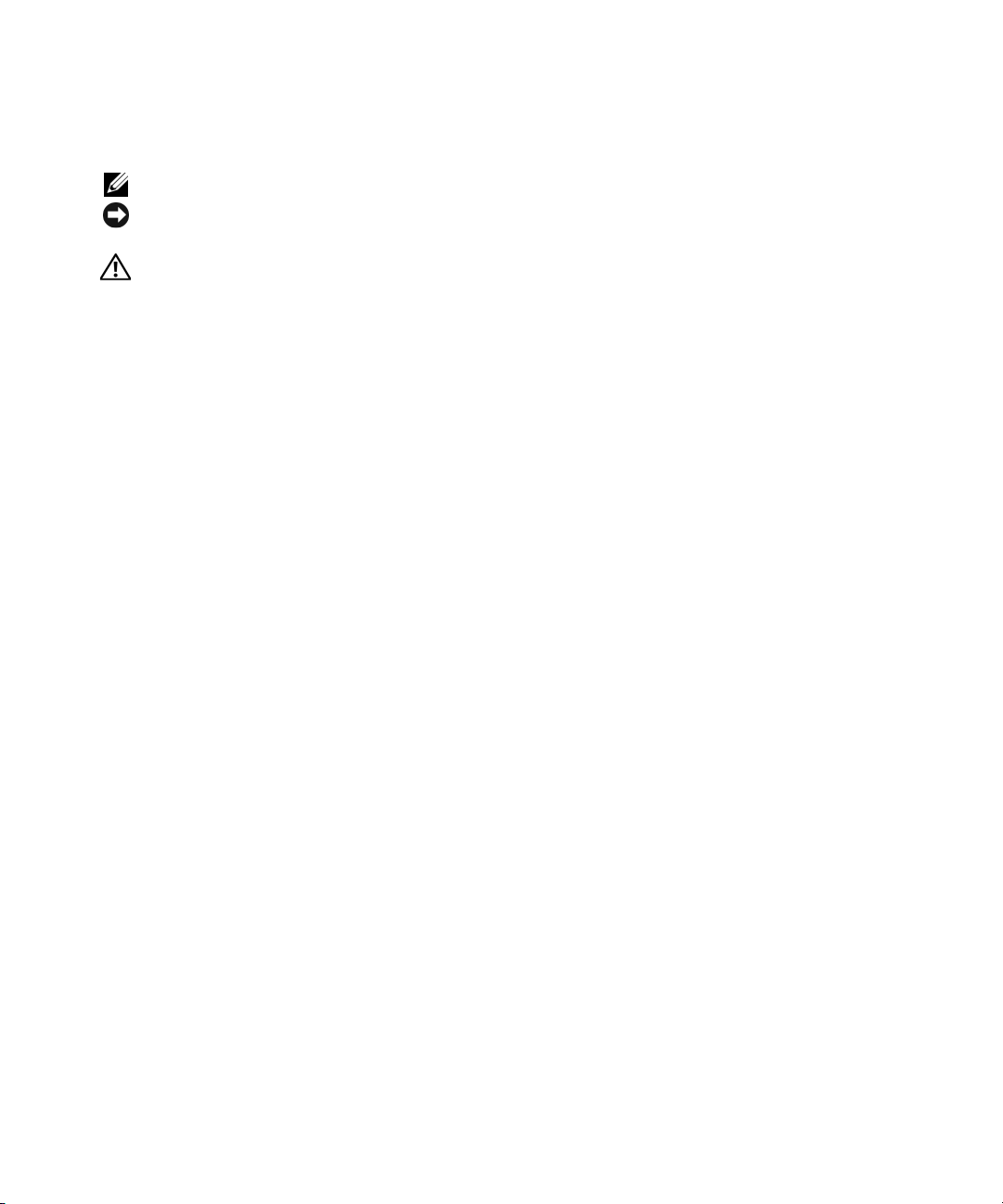
Unpacking the System
Unpack your system and identify each item.
Keep all shipping materials in case you need them later.
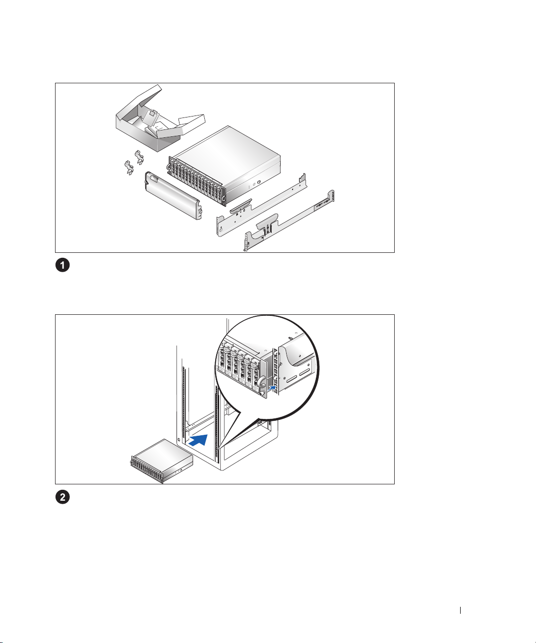
Installing the Rails and System in a Rack
Once you have read the "Safety Instructions" located in the rack installation documentation
for your system, install the rails and the system in the rack.
See your rack installation documentation for instructions on installing your system in a rack.
Getting Started With Your System 5
Page 8
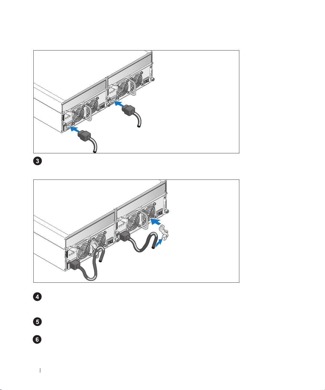
Connecting the Power Cables
Connect both power cables to the power supply/cooling fan modules.
Attaching the Power Cord Retention Bracket
Attach the power cord retention bracket to the power supply loop by affixing the back clasp of the
bracket to the top of the loop and the middle clasp to the vertical middle of the loop. Attach the
system power cable to the bracket’s cable clasp. Repeat the procedure for the second power supply.
Plug the other end of the power cables into a grounded electrical outlet or a separate power source
such as
an uninterruptible po
Cable the RAID controller modules according to the instructions provided in the
Owner’s Manual
.
wer supply (UPS) or a power distribution unit (PDU).
Hardware
6 Getting Started With Your System
Page 9
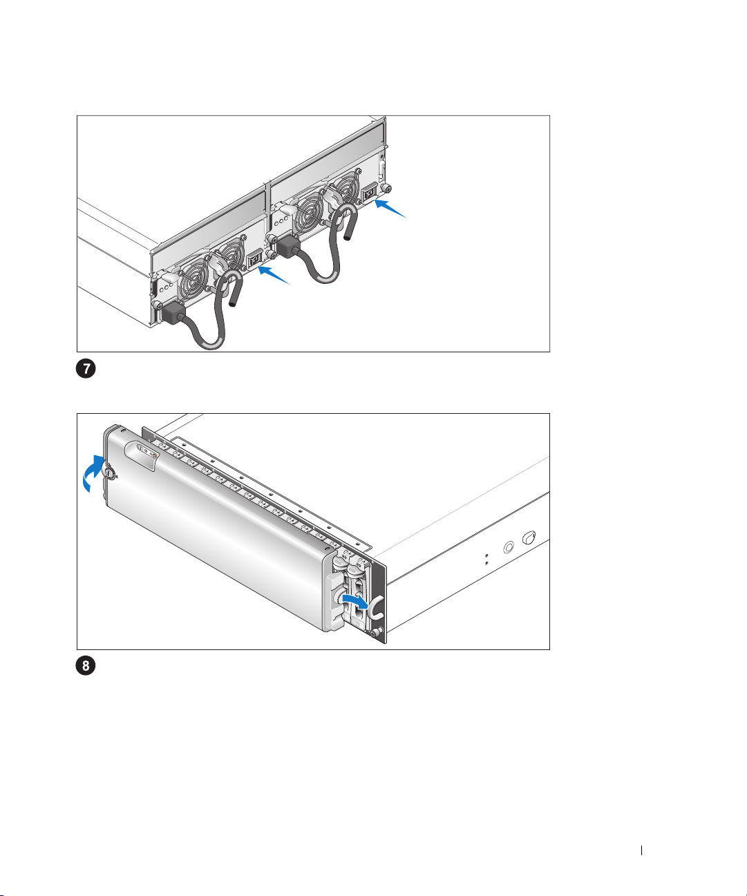
Turning on the System
Power on the system by turning on both power supply/cooling fan modules.
Installing the Bezel
Install the bezel (optional) by inserting the right edge of the bezel into the right front loop on the
system, and then pressing the left edge of the bezel to the system until the bezel snaps into place.
Getting Started With Your System 7
Page 10

Technical Specifications
Disks
Physical disks up to 15 1-inch-by-3.5-inch SAS and/or SATA II hot-plug physical
disks (3.0 Gbps). (See your system readme file for supported disk
capacities.)
RAID Controller Modules
RAID controllers
RAID Controller Back-Panel Connectors
SAS connectors (per RAID
controller)
Debug connector
(per RAID controller)
Ethernet connector
(per RAID controller)
Backplane Board
Connectors
Sensors 2 temperature sensors
LED Indicators
Front panel
Physical disk carrier
• 2 hot-pluggable active/active controllers
• 256 MB of cache per controller
• 1 temperature sensor per controller
• 1 SAS Port 0 "In" connector for connection to the host
• 1 SAS Port 1 "In" connector (if installed) for connection to an
additional host
• 1 SAS Port "Out" connector for expansion to an additional
enclosure
1 6-pin mini-DIN connector (debug port for Dell factory use only)
1 10/100 BASE-T connection for out-of-band management of the
enclosure
• 15 SAS physical-disk connectors
• 2 power supply/cooling fan module connectors
• 2 sets of RAID controller connectors (6 connectors each
controller)
• 1 control panel connector for front LEDs
• 1 two-color LED indicator for system status
• 2 single-color LED indicators (one for power; one nonfunctional)
• 1 single-color activity LED
• 1 two-color LED status indicator per disk
8 Getting Started With Your System
Page 11

RAID controllers The following single-color LEDs:
• Battery fault
• Cache active
• Controller fault
• Controller power
• Ethernet link
• Ethernet activity
• SAS Out fault
• SAS Out active
• SAS In fault (2 if additional In connector installed)
• SAS In active (2 if additional In connector installed)
Power supply/cooling fan
module
Power Supplies
Wattage 488 W maximum continuous; 550 W peak
Heat dissipation 200 W
Voltage 100–240 V rated (actual 90–264 V)
Frequency 47–63 Hz
Amperage 7.2 A at 100 V, 3.6 A at 200 V
Available Physical Disk Power (Per Slot)
Supported physical-disk power
consumption
Physical
Height 13.11 cm (5.16 inches)
Width 44.63 cm (17.57 inches)
Depth 48.01 cm (18.9 inches)
Weight (maximum
configuration)
3 LED status indicators for power supply status, power supply/fan
fault, and AC status
up to 1.3 A at +12 V
up to 1.5 A at +5 V
35.37 kg (78 lb)
Getting Started With Your System 9
Page 12

Environmental (Enclosure)
Temperature:
Operating
Storage
Relative humidity
Operating
Storage
Altitude
Operating
Storage
BTU per hour 1430
Environmental (Battery Backup Unit [BBU])
Maximum input power
Regulated output voltage
from BBU
Minimum retention time
(life expectancy)
Working temperature range
(dry bulb)
Working relative humidity
range
Storage temperature range
(dry bulb)
Transit temperature range
(dry bulb)
Storage and transit humidity
range
Storage and transit maximum
temperature gradient
Storage and transit maximum
humidity gradient
10° to 35°C (50° to 95°F)
–40° to 65°C (–40° to 149°F)
20% to 80% (noncondensing)
5% to 95% (noncondensing)
–16 to 3048 m (–50 to 10,000 ft)
–16 to 10,600 m (–50 to 35,000 ft)
• +12 VDC +/–5% at 1 A
• +3.3 VDC +/–5% at 150 mA
• Operating temperature range: 5° to 55°C (41° to 131°F)
• +2.5 VDC +/–3% at 20 mA to 120 mA
• Operating temperature range: 5° to 55°C (41° to 131°F)
72 hours for 256-MB DDR-I DIMM, 2.5 V at 120 mA
• 5° to 55°C (41° to 131°F)
• Maximum dry bulb temperature derated by 3.3°C (37.9°F)
per 1000 m (3281 ft) above 500 m (1640 ft)
5% to 90% noncondensing
• –10° to 45°C (14° to 113°F) for 3 months maximum
• Maximum dry bulb temperature derated by 3.3°C (37.9°F)
per 1000 m (3281 ft) above 500 m (1640 ft)
–20° to 60°C (–4° to 140°F) for 1 week maximum
5% to 95% relative humidity
1°C (33.8°F) per minute to a maximum of 20°C (68°F) per hour
30% relative humidity per hour
10 Getting Started With Your System
Page 13

Guide de mise
en route
www.dell.com | support.dell.com
Page 14

Remarques, avis et précautions
REMARQUE : une REMARQUE indique des informations importantes qui peuvent vous aider à mieux utiliser
votre système.
AVIS : un AVIS vous avertit d'un risque de dommage matériel ou de perte de données et vous indique comment éviter
le problème.
PRÉCAUTION : une PRÉCAUTION indique un risque potentiel d'endommagement du matériel, de blessure corporelle
ou de mort.
____________________
Les informations contenues dans ce document peuvent être modifiées sans préavis.
© 2005 Dell Inc. Tous droits réservés.
La reproduction de ce document de quelque manière que ce soit sans l'autorisation écrite de Dell Inc. est strictement interdite.
Marques utilisées dans ce document : Dell et le logo DELL sont des marques de Dell Inc.
Tous les autres noms de marques et marques commerciales utilisés dans ce document se rapportent aux sociétés propriétaires des marques et
des noms de ces produits. Dell Inc. décline tout intérêt dans l'utilisation des marques déposées et des noms de marques ne lui appartenant pas.
Modèle AMP01
Novembre 2005 P/N FF454 Rev. A00
Page 15

Caractéristiques du système
Cette section décrit les principales caractéristiques du système sur le plan matériel et logiciel.
Elle contient également des informations sur les autres documents utiles à la configuration du
système et sur l'obtention d'assistance technique.
Les caractéristiques principales du système sont les suivantes :
• Conception optimisée pour un montage en rack
• Possibilité d'installer 15 disques durs SAS (Serial-attached SCSI) à 3,0 Gbps (disques de 1 pouce
enfichables à chaud) et/ou disques physiques SATA II (Serial Advanced Technology Attachment II)
• Carte SAS 5/E permettant de connecter la matrice de stockage à un ou plusieurs serveurs
REMARQUE : le démarrage du système à partir d'un périphérique externe connecté à une carte SAS ou
SCSI n'est pas pris en charge (cartes SAS 5/E, PERC 5/E, PERC 4e/DC et PERC 4/DC incluses). Voir le site
support.dell.com pour obtenir les informations les plus récentes concernant le démarrage à partir de
périphériques externes.
• Blocs d'alimentation et modules de refroidissement redondants et enfichables à chaud, combinés
en un seul bloc pour faciliter la maintenance du système
• Deux modules de contrôleur RAID de type actif/actif permettant une mise en redondance des
données et des fonctions de gestion du système
• Prise en charge d'un maximum de deux châssis reliés en série (soit un total de 45 disques
physiques)
• Configuration et contrôle via le logiciel MD Storage Manager
• Quatre capteurs assurant le contrôle des températures ambiantes
• Une unité de batterie de sauvegarde (BBU) permettant d'alimenter la mémoire système
du contrôleur RAID (mémoire cache) en cas de coupure de courant
• Fonction de coupure en cas de surchauffe
• Prise en charge d'une gamme de serveurs très étendue. Consultez le fichier readme du système
pour obtenir la liste des systèmes pris en charge. La version la plus récente de ce fichier se trouve
sur le site
support.dell.com
.
Guide de mise en route 13
Page 16

Autres informations utiles
PRÉCAUTION : le Guide d'informations sur le produit contient d'importantes informations se rapportant à la
sécurité et aux réglementations. Les informations sur la garantie se trouvent soit dans ce document, soit à part.
• Le document
la solution rack décrivent l'installation du système.
• Le document
les caractéristiques du système, ainsi que des instructions relatives au dépannage et à l'installation
ou au remplacement de composants.
• Le disque “Resource CD” fourni avec le système contient des documents et des outils relatifs à la
configuration et à la gestion du système.
• Des notes de version ou des fichiers lisez-moi (readme) sont parfois fournis ; ils contiennent des mises
à jour de dernière minute apportées au système ou à la documentation, ou des documents de référence
technique avancés destinés aux utilisateurs expérimentés ou aux techniciens.
Instructions d'installation du rack
Hardware Owner's Manual
(Manuel du propriétaire) contient des informations sur
ou le
Guide d'installation du rack
fournis avec
Obtention d'une assistance technique
Si vous ne comprenez pas une procédure décrite dans ce guide ou si le système ne réagit pas comme
prévu, consultez le document Hardware Owner's Manual (Manuel du propriétaire).
Des formations et certifications Dell Enterprise sont disponibles. Pour plus d'informations, consultez
le site www.dell.com/training. Ce service n'est disponible que dans certains pays.
Installation et configuration
PRÉCAUTION : avant d'exécuter la procédure suivante, lisez les consignes de sécurité et les informations
importantes sur les réglementations figurant dans le Guide d'informations sur le produit. Veillez à les respecter
scrupuleusement.
Cette section décrit les étapes à exécuter lors de la configuration initiale du système.
14 Guide de mise en route
Page 17

Déballage du système
Sortez le système de son emballage et identifiez chaque élément fourni.
Conservez les matériaux d'emballage au cas où vous en auriez besoin ultérieurement.
Installation des rails et du système dans un rack
Commencez par lire les consignes de sécurité qui se trouvent dans la documentation d'installation
du rack, puis installez les rails et le système dans le rack.
Consultez la documentation d'installation du rack pour obtenir les instructions appropriées.
Guide de mise en route 15
Page 18

Connexion des cordons d'alimentation
Branchez les deux cordons d'alimentation sur les modules d'alimentation et de ventilation.
Fixation du support du cordon d'alimentation
Installez le support du cordon d'alimentation. Pour ce faire, attachez le clip arrière sur le haut de la
poignée prévue à cet effet et le clip intermédiaire sur le milieu de la poignée. Ensuite, faites passer
le cordon d'alimentation dans le troisième clip du support. Recommencez cette procédure pour le
second bloc d'alimentation.
Branchez ensuite l'autre extrémité des cordons d'alimentation sur une prise de courant mise à la terre
ou sur une source d'alimentation autonome
Câblez les modules de contrôleur RAID en suivant les instructions du guide
(onduleur ou
unité de distribution de l'alimentation
Hardware Owner’s Manual
(Manuel du propriétaire).
16 Guide de mise en route
).
Page 19

Mise sous tension du système
Mettez le système sous tension en allumant les deux modules d'alimentation et de ventilation.
Installation du cadre
Pour installer le cadre en option, insérez sa partie droite dans la boucle de droite située à l'avant
du système, puis appuyez sur sa partie gauche jusqu'à ce que le cadre s'emboîte sur le système.
Guide de mise en route 17
Page 20

Caractéristiques techniques
Disques
Disques physiques Jusqu'à 15 disques physiques SAS et/ou SATA II enfichables à
chaud de 1 x 3,5 pouces (3,0 Gbps). Consultez le fichier Readme
pour savoir quelles sont les capacités prises en charge.
Modules de contrôleur RAID
Contrôleurs RAID
Connecteurs de contrôleur RAID sur le panneau arrière
Connecteurs SAS (pour chaque
contrôleur RAID)
Connecteur de débogage
(pour chaque contrôleur RAID)
Connecteur Ethernet (pour
chaque contrôleur RAID)
Carte de fond de panier
Connecteurs
Capteurs 2 capteurs de température
Voyants
Panneau avant
Support de disque physique
• 2 contrôleurs actif/actif, enfichables à chaud
• 256 Mo de mémoire cache par contrôleur
• 1 capteur de température par contrôleur
• 1 connecteur SAS “In” (Port 0) pour la connexion à l'hôte
• 1 connecteur SAS “In” (Port 1, s'il est installé) pour la connexion
à un hôte supplémentaire
• 1 connecteur SAS “OUT” pour l'ajout d'un châssis
supplémentaire
1 connecteur mini-DIN à 6 broches (utilisation en usine réservée
à Dell)
1 connexion 10/100 BASE-T pour la gestion hors bande du châssis
• 15 connecteurs de disques physiques SAS
• 2 connecteurs de modules d'alimentation et de ventilation
• 2 ensembles de connecteurs pour contrôleur RAID (6 connecteurs
pour chaque contrôleur)
• 1 connecteur de panneau de commande pour les voyants frontaux
• 1 voyant bicolore indiquant l'état du système
• 2 voyants monochromes (un voyant d'alimentation et un voyant
de panne)
• 1 voyant d'activité monochrome
• 1 voyant d'état bicolore par disque
18 Guide de mise en route
Page 21

Contrôleurs RAID Voyants monochromes :
• Pile défectueuse
• Mémoire cache active
• Panne du contrôleur
• Alimentation du contrôleur
• Liaison Ethernet
• Activité Ethernet
• Panne sur le port SAS “Out”
• Port SAS “Out” actif
• Panne sur le port SAS “In” (2 si le connecteur “In”
supplémentaire est installé)
• Port SAS “In” actif ((2 si le connecteur “In” supplémentaire
est installé)
Module d'alimentation
et de ventilation
Blocs d'alimentation
Puissance Puissance maximale de 488 W en continu ; puissance de pointe
Dissipation thermique 200 W
Tension Nominale : 100–240 V (réelle 90–264 V)
Fréquence 47-63 Hz
Intensité du courant 7,2 A à 100 V ; 3,6 A à 200 V
Alimentations disponibles pour les disques physiques (par logement)
Consommation prise en charge
pour les disques physiques
Caractéristiques physiques
Hauteur 13,11 cm (5,16 pouces)
Largeur 44,63 cm (17,57 pouces)
Profondeur 48,01 cm (18,9 pouces)
Poids (configuration maximale) 35,37 kg (78 livres)
3 voyants d'état (état du bloc d'alimentation, panne du module
d'alimentation/ventilation et état de l'alimentation en CA)
de 550 W
Jusqu'à 1,3 A à +12 V
Jusqu'à 1,5 A à +5 V
Guide de mise en route 19
Page 22

Environnement (châssis)
Température :
Fonctionnement
Stockage
Humidité relative
Fonctionnement
Stockage
Altitude
Fonctionnement
Stockage
BTU/h 1 430 (360 kcal/h)
Environnement (unité de batterie de sauvegarde [BBU])
Puissance d'entrée maximale
Tension de sortie régulée
de la BBU
Délai minimal de rétention 72 heures pour une barrette DIMM DDR-I de 256 Mo
Température de fonctionnement
(environnement sec)
Taux d'humidité relative
de l'environnement de
fonctionnement
Température de stockage
(environnement sec)
Température de transport
(environnement sec)
Taux d'humidité de
l'environnement de stockage
et de transport
Gradient thermique maximal
pour le stockage et le transport
Gradient d'humidité maximal
pour le stockage et le transport
De 10° à 35° C (50 à 95° F)
De -40° à 65° C (-40° à 149 °F)
De 20 à 80 % (sans condensation)
De 5 % à 95 % (sans condensation)
De -16 à 3 048 m (-50 à 10 000 pieds)
De -16 à 10 600 m (–50 à 35 000 pieds)
• +12 VCC +/–5% à 1 A
• +3,3 VCC +/–5% à 150 mA
• Température de fonctionnement : de 5° à 55°C (41° à 131°F)
• +2,5 VCC +/–3% (20 mA à 120 mA)
• Température de fonctionnement : de 5° à 55°C (41° à 131°F)
(2,5 V à 120 mA)
• de 5° à 55°C (41° à 131°F)
• Valeur nominale réduite de 3,3°C (37,9°F) tous les 1 000 m
(3 281 pieds) à partir de 500 m (1 640 pieds)
5% à 90% (sans condensation)
• de –10° à 45°C (14° à 113°F) pendant 3 mois maximum
• Valeur nominale réduite de 3,3°C (37,9°F) tous les 1 000 m
(3 281 pieds) à partir de 500 m (1 640 pieds)
De –20° à 60°C (–4° à 140°F) pendant 1 semaine maximum
De 5% à 95% d'humidité relative
De 1°C (33,8°F) par minute jusqu'à un maximum de 20°C (68°F)
par heure
30% d'humidité relative par heure
20 Guide de mise en route
Page 23

Primeiros passos
com o sistema
www.dell.com | support.dell.com
Page 24

Observações, avisos e cuidados
OBSERVAÇÃO: As OBSERVAÇÕES indicam informações importantes que o ajudam a utilizar melhor o sistema.
AVISO: As mensagens de AVISO informam sobre possíveis danos ao hardware ou perda de dados e indicam
como evitar o problema.
CUIDADO: As mensagens de CUIDADO indicam possíveis danos à propriedade, ferimentos pessoais ou morte.
____________________
As informações contidas neste documento estão sujeitas a alterações sem aviso prévio.
© 2005 Dell Inc. Todos os direitos reservados.
É terminantemente proibida a reprodução de qualquer natureza sem a autorização por escrito da Dell Inc.
Marcas comerciais mencionadas neste texto: Dell e o logotipo da DELL são marcas comerciais da Dell Inc.
Outras marcas e nomes comerciais podem ser mencionados neste documento em referência às entidades proprietárias das marcas e nomes ou
a seus produtos. A Dell Inc. renuncia ao direito de qualquer participação em nomes e marcas comerciais que não sejam de sua propriedade.
Modelo AMP01
Novembro de 2005 P/N FF454 Rev. A00
Page 25

Recursos do sistema
Esta seção descreve os principais recursos de hardware e software do sistema. Também fornece
informações sobre outros documentos de que talvez necessite quando configurar o sistema e
sobre como obter assistência técnica.
Os principais recursos do sistema incluem:
• Eficiente sistema de armazenamento projetado para montagem em rack.
• Capacidade para 15 discos físicos SCSI (SAS) e/ou Serial Advanced Technology Attachment II
(SATA II) de 3.0 Gbps, de 1 polegada, com conexão automática e ligação em série.
• Adaptador SAS 5/E para conexão da matriz de armazenamento aos servidores.
OBSERVAÇÃO: A inicialização do sistema não tem suporte de dispositivos externos conectados
ao adaptador SAS ou SCSI, incluindo SAS 5/E, PERC 5/E, PERC 4e/DC ou PERC 4/DC. Visite o site
support.dell.com (em Inglês) para obter as informações de suporte mais recentes sobre a inicialização
a partir de dispositivos externos.
• Fonte de alimentação redundante de conexão automática e módulos de resfriamento combinados
para fácil manutenção.
• Dois módulos do controlador RAID ativo/ativo para proporcionar capacidade de gerenciamento
redundante do sistema e dos dados.
• Suporte para até dois invólucros de armazenamento conectados em margarida para um total
de 45 discos físicos.
• Configuração e monitoramento através do software MD Storage Manager
(Gerenciador de armazenamento MD).
• Quatro sensores para o monitoramento da temperatura ambiente.
• Unidade de bateria de backup (BBU) para alimentar a memória do sistema do controlador RAID
(cache) caso haja interrupção no fornecimento de energia.
• Capacidade de desligamento devido ao sobreaquecimento.
• Suporte para ampla variedade de servidores. Consulte o arquivo leia-me do sistema para conhecer
os sistemas com suporte. Visualize o arquivo leia-me atualizado no site da Dell, no endereço
support.dell.com
(em Inglês).
Primeiros passos com o sistema 23
Page 26

Outras informações úteis
CUIDADO: O Guia de informações do produto fornece informações importantes sobre segurança e
regulamentação. As informações sobre garantia podem estar incluídas nesse documento ou ser fornecidas
como documento separado.
• O documento
Guide
(Guia para instalação em rack) incluído com a solução em rack descreve como instalar o sistema
em racks.
Hardware Owner’s Manual
•O
recursos do sistema e descreve como solucionar problemas do sistema e instalar ou substituir seus
componentes.
• O Resource CD incluído com o sistema fornece documentação e ferramentas para a configuração
e o gerenciamento do sistema.
• Talvez existam notas de versão e arquivos leia-me incluídos para fornecer as atualizações mais recentes
do sistema ou documentação/material para referência técnica avançada destinados a usuários
experientes ou técnicos.
Rack Installation Instructions
(Manual do proprietário de hardware) fornece informações sobre os
(Instruções para montagem em rack) ou
Rack Installation
Como obter assistência técnica
Se não compreender algum procedimento descrito neste guia ou se o sistema não apresentar o
desempenho esperado, consulte o Hardware Owner’s Manual (Manual do proprietário de hardware).
Existem recursos de treinamento e certificação empresarial da Dell; visite o site www.dell.com/training
(em Inglês) para obter mais informações. Esse serviço pode não ser oferecido em todos os locais.
Instalação e configuração
CUIDADO: Antes de realizar o seguinte procedimento, leia e siga as instruções de segurança e as informações
importantes sobre regulamentação contidas no Guia de informações do produto.
Esta seção descreve as etapas para a configuração do sistema pela primeira vez.
24 Primeiros passos com o sistema
Page 27

Remoção do sistema da embalagem
Remova o sistema da embalagem e identifique cada item.
Guarde todos os materiais de envio caso sejam necessários mais tarde.
Instalação dos trilhos e do sistema no rack
Depois de ler as instruções de segurança localizadas na documentação de instalação do rack para
o sistema, instale os trilhos e o sistema no rack.
Consulte o documento de instalação do rack para obter instruções sobre como instalar o sistema
em um rack.
Primeiros passos com o sistema 25
Page 28

Conexão dos cabos de alimentação
Conecte os cabos de alimentação à fonte de alimentação e aos módulos de ventiladores de resfriamento.
Como conectar o suporte de retenção do cabo de alimentação
Conecte o suporte de retenção do cabo de alimentação à presilha na fonte de alimentação fixando
o colchete posterior do suporte à parte superior da presilha e o colchete do meio à parte vertical
no meio da presilha. Conecte o cabo de alimentação do sistema ao colchete do cabo localizado
no suporte. Repita o procedimento para a segunda fonte de alimentação.
Conecte a outra extremidade do cabo a uma tomada elétrica aterrada ou a uma fonte de energia
separada como, por exemplo, uma
ininterrupta)
Conecte os módulos do controlador RAID de acordo com as instruções fornecidas no
Owner’s Manual
ou uma PDU (Power Distribution Unit – Unidade de distribuição de energia).
(Manual do proprietário de hardware).
UPS (Uninterruptible Power Supply – Fonte de alimentação
Hardware
26 Primeiros passos com o sistema
Page 29

Como ligar o sistema
Ative o sistema ligando a fonte de alimentação e os módulos de ventiladores de resfriamento.
Instalação do painel
Instale o painel (opcional) inserindo a borda direita do painel na presilha frontal direita do sistema
e pressionando a borda esquerda do painel contra o sistema até que se encaixe no lugar.
Primeiros passos com o sistema 27
Page 30

Especificações técnicas
Discos
Discos físicos Até 15 discos físicos SAS e/ou SATA II de 1 x 3,5 pol. (3.0 Gbps)
com conexão automática. Consulte o arquivo leia-me do sistema
para conhecer as capacidades de disco admitidas.
Módulos do controlador RAID
Controladores RAID
Conectores do painel posterior do controlador RAID
Conectores SAS (por
controlador RAID)
Conector de depuração
(por controlador RAID)
Conector Ethernet (por
controlador RAID)
Placa de backplane
Conectores
Sensores 2 sensores de temperatura.
LEDs indicadores
Painel frontal
Carregador do disco físico
• 2 controladores ativo/ativo com conexão automática.
• 256 MB de cache por controlador.
• 1 sensor de temperatura por controlador.
• 1 conector SAS da porta 0 “In” para conexão ao host.
• 1 conector SAS da porta 1 “In” (se instalada) para conexão ao host
adicional.
• 1 conector SAS da porta “Out” para expansão de invólucro
adicional.
1 conector mini-DIN de seis pinos (porta de depuração somente
para uso da fábrica Dell).
1 conexão BASE-T 10/100 para gerenciamento out-of-band
do invólucro.
• 15 conectores de disco físico SAS.
• 2 conectores de fonte de alimentação/módulos de ventiladores
de resfriamento.
• 2 conjuntos de conectores do controlador RAID
(6 conectores para cada controlador).
• 1 conector do painel de controle para os LEDs frontais.
• 1 LED indicador de duas cores para o status do sistema.
• 2 LEDs indicadores de cor única (um para energia; um não
funcional).
• 1 LED de atividade de cor única.
• 1 LED indicador de status de duas cores por disco.
28 Primeiros passos com o sistema
Page 31

Controladores RAID Os seguintes LEDs de cor única:
• Falha da bateria
• Cache ativo
• Falha do controlador
• Energia do controlador
• Conexão da Ethernet
• Atividade da Ethernet
• Falha do conector Out SAS
• Conector Out SAS ativo
• Falha do conector In SAS (2 se o conector In adicional estiver
instalado)
• Conector In SAS ativo (2 se o conector In adicional estiver
instalado)
Fonte de alimentação/módulo
de ventiladores de resfriamento
Fontes de alimentação
Potência 488 W contínua máxima; pico de 550 W.
Dissipação de calor 200 W.
Voltagem 100 - 240 V nominal (real de 90-264 V).
Freqüência 47 - 63 Hz.
Amperagem 7,2 A a 100 V; 3,6 A a 200 V.
Potência disponível dos discos físicos (por slot)
Consumo de energia do disco
físico admitido
Aspectos físicos
Altura 13,11 cm (5,16 polegadas).
Largura 44,63 cm (17,57 polegadas).
Profundidade 48,01 cm (18,9 polegadas).
Peso (configuração máxima) 35,37 kg (78 libras).
3 LEDs indicadores para status da fonte de alimentação, falha de
fonte alimentação/ventilador e status da corrente alternada (CA).
Até 1,3 A a +12 V.
Até 1,5 A a +5 V.
Primeiros passos com o sistema 29
Page 32

Aspectos ambientais (Invólucro)
Temperatura:
Operacional
Armazenamento
Umidade relativa
Operacional
Armazenamento
Altitude
Operacional
Armazenamento
BTUs por hora 1430.
Aspectos ambientais (Unidade de bateria de backup [BBU]).
Energia de entrada máxima
Voltagem de saída regulada
da BBU
Tempo de retenção mínimo
(expectativa de vida útil)
Intervalo de temperatura em
funcionamento (lâmpada seca)
Intervalo da umidade relativa
em funcionamento
Intervalo da temperatura de
armazenamento (lâmpada seca)
Intervalo de temperatura
em trânsito (lâmpada seca)
Intervalo da umidade de
armazenamento e em trânsito
Gradiente máximo da temperatura de armazenamento e
em trânsito
Gradiente máximo da umidade
de armazenamento e em trânsito
10 °C a 35 °C (50 °F a 95 °F).
-40 °C a 65 °C (-40 °F a 149 °F).
20% a 80% (sem condensação).
5% a 95% (sem condensação).
-16 m a 3.048 m (-50 a 10.000 pés).
-16 a 10.600 m (-50 a 35.000 pés).
• +12 VCC +/–5% a 1 A.
• +3,3 VCC +/–5% a 150 mA.
• Intervalo de temperatura operacional: 5 °C a 55 °C
(41 °F a 131 °F).
• +2,5 VCC +/–3% de 20 mA a 120 mA.
• Intervalo de temperatura operacional: 5 °C a 55 °C
(41 °F a 131 °F).
72 horas para DIMM DDR-I de 256-MB, 2,5 V a 120 mA.
• 5 °C a 55 °C (41 °F a 131 °F).
• Temperatura mínima da lâmpada seca avaliada em 3,3 °C
(37,9 °F) por 1.000 m (3.281 pés) acima de 500 m (1.640 pés).
5% a 90% sem condensação.
• -10 °C a 45 °C (14 °F a 113 °F) por 3 meses no máximo.
• Temperatura mínima da lâmpada seca avaliada em 3,3 °C
(37,9 °F) por 1.000 m (3.281 pés) acima de 500 m (1.640 pés).
-20 °C a 60 °C (-4 °F a 140 °F) por 1 semana no máximo.
Umidade relativa de 5% a 95%
1 °C (33,8 °F) por minuto ao máximo de 20 °C (68 °F) por hora.
Umidade relativa de 30% por hora.
30 Primeiros passos com o sistema
Page 33

Procedimientos iniciales
con el sistema
www.dell.com | support.dell.com
Page 34

Notas, avisos y precauciones
NOTA: una NOTA proporciona información importante que le ayudará a utilizar mejor el sistema.
AVISO: un AVISO indica la posibilidad de daños en el hardware o la pérdida de datos, e informa de cómo evitar
el problema.
PRECAUCIÓN: un mensaje de PRECAUCIÓN indica el riesgo de daños materiales, lesiones o incluso la muerte.
____________________
La información contenida en este documento puede modificarse sin previo aviso.
© 2005 Dell Inc. Reservados todos los derechos.
Queda estrictamente prohibida la reproducción de este documento en cualquier forma sin la autorización por escrito de Dell Inc.
Marcas comerciales utilizadas en este texto: Dell y el logotipo de DELL son marcas comerciales de Dell Inc.
Otras marcas y otros nombres comerciales pueden utilizarse en este documento para hacer referencia a las entidades que los poseen
o a sus productos. Dell Inc. renuncia a cualquier interés sobre la propiedad de marcas y nombres comerciales que no sean los suyos.
Modelo AMP01
Noviembre de 2005 P/N FF454 Rev. A00
Page 35

Características del sistema
En esta sección se describen las principales características de hardware y software del sistema.
También se ofrece información sobre otros documentos que puede necesitar al instalar el sistema
y sobre cómo obtener asistencia técnica.
Las principales características del sistema son:
• Sistema de almacenamiento eficiente de montaje en rack
• Capacidad para 15 discos físicos SCSI conectados en serie (SAS) y/o SATA II (dispositivo conector
de tecnología avanzada serie II) de 3 Gbps, acoplamiento activo y 1 pulgada
• Adaptador SAS 5/E para conectar la matriz de almacenamiento al servidor o los servidores
NOTA: no es posible iniciar el sistema desde un dispositivo externo conectado a un adaptador SAS o
SCSI, incluido SAS 5/E, PERC 5/E, PERC 4e/DC o PERC 4/DC. Para obtener información sobre cómo iniciar
el sistema desde dispositivos externos, visite support.dell.com.
• Módulos redundantes de refrigeración y fuente de alimentación de acoplamiento activo para
facilitar las reparaciones
• Dos módulos de controladora RAID activo/activo para permitir la administración de sistemas
y datos redundantes
• Soporte para un máximo de dos alojamientos para almacenamiento conectados secuencialmente
para un total de 45 discos físicos
• Configuración y supervisión a través del software MD Storage Manager
• Cuatro sensores para supervisar la temperatura ambiente
• Unidad de reserva de batería (BBU) para alimentar la memoria de sistema (caché) de la controladora RAID en caso de interrumpirse la alimentación
• Capacidad de apagado del sistema en caso de exceso de temperatura
• Soporte para una amplia gama de servidores. Consulte el archivo Léame del sistema para ver una
relación de los sistemas admitidos. Encontrará un archivo Léame actualizado en la página Web
de Dell (
support.dell.com
).
Procedimientos iniciales con el sistema 33
Page 36

Otra información necesaria
PRECAUCIÓN: en la Guía de información del producto se proporciona información importante sobre seguridad
y normativas. La información de la garantía puede estar incluida en este documento o constar en un documento
aparte.
• En los documentos
el rack se describe cómo instalar el sistema en un rack.
• En el
• El CD de recursos que se suministra con el sistema proporciona documentación y herramientas
• Es posible que se incluyan notas de la versión o archivos Léame para proporcionar actualizaciones
Manual del propietario del hardware
sistema y se describe cómo solucionar problemas del sistema e instalar o reemplazar componentes
del sistema.
para configurar y administrar el sistema.
de última hora relativas al sistema o a la documentación, o material de consulta técnica avanzada
destinado a técnicos o usuarios experimentados.
Instrucciones de instalación del rack
se proporciona información sobre las características del
o
Guía de instalación del rack
incluidos con
Obtención de asistencia técnica
Si no comprende un procedimiento de esta guía o si el sistema no funciona del modo esperado,
consulte el Manual del propietario del hardware.
Tiene a su disposición el servicio de formación y certificación Dell para empresas. Para obtener más
información, visite www.dell.com/training. Es posible que este servicio no se ofrezca en todas las
regiones.
Instalación y configuración
PRECAUCIÓN: antes de realizar el procedimiento siguiente, lea y siga las instrucciones de seguridad
y la información importante sobre normativas incluidas en la Guía de información del producto.
En esta sección se describen los pasos para configurar el sistema por primera vez.
34 Procedimientos iniciales con el sistema
Page 37

Desembalaje del sistema
Desembale el sistema e identifique cada elemento.
Guarde el material de embalaje por si lo necesitara más adelante.
Instalación de los rieles y del sistema en un rack
Una vez que haya leído las “Instrucciones de seguridad” de la documentación del sistema relativa
a la instalación del rack , instale los rieles y el sistema en el rack.
Consulte la documentación de instalación del rack para obtener instrucciones sobre la instalación
del sistema en un rack.
Procedimientos iniciales con el sistema 35
Page 38

Conexión de los cables de alimentación
Conecte los dos cables de alimentación a los módulos de fuente de alimentación/ventilador
de refrigeración.
Fijación del soporte de retención del cable de alimentación
Sujete el soporte de retención del cable de alimentación al asa de la fuente de alimentación fijando
la abrazadera posterior del soporte a la parte superior del asa y la abrazadera intermedia a la mitad
vertical del asa. Fije el cable de alimentación del sistema a la abrazadera correspondiente del
soporte. Repita el procedimiento para la segunda fuente de alimentación.
Conecte el extremo opuesto de los cables de alimentación a una toma eléctrica con conexión a tierra
o a otra fuente de alimentación, como
de distribución de alimentación (PDU)
Cablee los módulos de controladora RAID según las instrucciones proporcionadas en el
del propietario del hardware
.
un sistema de alimentación
.
ininterrumpida (SAI) o una unidad
Manual
36 Procedimientos iniciales con el sistema
Page 39

Encendido del sistema
Encienda el sistema activando los dos módulos de fuente de alimentación/ventilador de refrigeración.
Instalación del embellecedor
Instale el embellecedor (opcional) insertando el extremo derecho del embellecedor en el asa frontal
derecha del sistema y luego presionando el extremo izquierdo del embellecedor contra el sistema
hasta que quede bien encajado.
Procedimientos iniciales con el sistema 37
Page 40

Especificaciones técnicas
Discos
Discos físicos Hasta 15 discos físicos SAS y/o SATA II de acoplamiento activo de
1 x 3,5 pulgadas (3 Gbps). Consulte el archivo Léame del sistema
para ver las capacidades de disco admitidas.
Módulos de controladora RAID
controladoras RAID
Conectores del panel posterior de la controladora RAID
Conectores SAS
(por controladora RAID)
Conector de depuración
(por controladora RAID)
Conector Ethernet
(por controladora RAID)
Tarjeta de plano posterior
Conectores
Sensores 2 sensores de temperatura
Indicadores LED
Panel frontal
Portaunidades de disco físico
• 2 controladoras activo/activo de acoplamiento activo
• 256 MB de caché por controladora
• 1 sensor de temperatura por controladora
• 1 conector de puerto 0 SAS “de entrada” para conexión al host
• 1 conector de puerto 1 SAS “de entrada” (si está instalado)
para conexión a un host adicional
• 1 conector de puerto SAS “de salida” para expansión a un
alojamiento adicional
1 miniconector DIN de 6 patas (puerto de depuración sólo para
uso en fábrica de Dell)
1 conexión 10/100 BASE-T para la administración fuera de banda
del alojamiento
• 15 conectores de disco físico SAS
• 2 conectores de módulo de fuente de alimentación/ventilador
de refrigeración
• 2 conjuntos de conectores de controladora RAID
(6 conectores cada controladora)
• 1 conector del panel de control para LED frontales
• 1 indicador LED de dos colores de estado del sistema
• 2 indicadores LED de un solo color (uno para alimentación;
otro para no funcionamiento)
• 1 LED de actividad de un solo color
• 1 indicador LED de estado de dos colores por disco
38 Procedimientos iniciales con el sistema
Page 41

Controladoras RAID Los siguientes LED de un solo color:
• Error de batería
• Caché activa
• Error de controladora
• Alimentación de controladora
• Enlace Ethernet
• Actividad Ethernet
• Error de SAS de salida
• SAS de salida activo
• Error de SAS de entrada (2 si hay instalado un conector
de entrada adicional)
• SAS de entrada activo (2 si hay instalado un conector de entrada
adicional)
Módulo de fuente de
alimentación/ventilador
de refrigeración
Fuentes de alimentación
Potencia 488 W continuos como máximo; pico de 550 W
Disipación de calor 200 W
Voltaje 100–240 V nominal (90–264 V real)
Frecuencia 47–63 Hz
Amperaje 7,2 A a 100 V; 3,6 A a 200 V
Alimentación del disco físico disponible (por ranura)
Consumo de energía admitido
para el disco físico
Características físicas
Altura 13,11 cm
Anchura 44,63 cm
Profundidad 48,01 cm
Peso (configuración máxima) 35,37 kg
3 indicadores LED de estado para el estado de la fuente de
alimentación, los fallos del ventilador o la fuente de alimentación
y el estado de CA
Hasta 1,3 A a +12 V
Hasta 1,5 A a +5 V
Procedimientos iniciales con el sistema 39
Page 42

Especificaciones ambientales (alojamiento)
Temperatura:
En funcionamiento
En almacenamiento
Humedad relativa
En funcionamiento
En almacenamiento
Altitud
En funcionamiento
En almacenamiento
BTU por hora 1430
Especificaciones ambientales (unidad de reserva de batería [BBU])
Alimentación de entrada
máxima
Voltaje de salida regulado
desde la BBU
Tiempo de retención mínimo
(expectativas de vida)
Intervalo de temperaturas
de trabajo (bulbo seco)
Intervalo de humedad relativa
de trabajo
Intervalo de temperaturas de
almacenamiento (bulbo seco)
Intervalo de temperaturas
de transporte (bulbo seco)
Intervalo de humedad en
almacenamiento y transporte
Gradiente de temperatura
máxima de almacenamiento
y transporte
Gradiente de humedad máxima
de almacenamiento y transporte
De 10 °C a 35 °C
De –40 °C a 65 °C
Del 20 al 80 % (sin condensación)
Del 5 al 95 % (sin condensación)
De –16 a 3 048 m
De –16 a 10 600 m
• +12 V CC +/–5 % a 1 A
• +3,3 V CC +/–5 % a 150 mA
• Intervalo de temperaturas de funcionamiento: De 5 °C a 55 °C
• +2,5 V CC +/–3 % a 20 mA hasta 120 mA
• Intervalo de temperaturas de funcionamiento: De 5 °C a 55 °C
72 horas para DIMM DDR-I de 256 MB, 2,5 V a 120 mA
• De 5 °C a 55 °C
• Temperatura máxima de bulbo seco reducida en 3,3 °C por cada
1 000 m por encima de 500 m
Del 5 al 90 % sin condensación
• De –10 °C a 45 °C durante 3 meses como máximo
• Temperatura máxima de bulbo seco reducida en 3,3 °C por cada
1 000 m por encima de 500 m
De –20 °C a 60 °C durante 1 semana como máximo
Humedad relativa del 5 % al 95 %
1 °C por minuto a un máximo de 20 °C por hora
Humedad relativa del 30 % por hora
40 Procedimientos iniciales con el sistema
 Loading...