

Page 1

Getting Started
With Your System
Začínáme se systémem
Guide de mise en route
Erste Schritte mit dem System
Τα πρώτα βήματα Με το σύστημά σας
Rozpoczecie pracy z systemem
Начало работы с системой
Procedimientos iniciales con el sistema
Sistem Başlangıç Kılavuzu
Model AMP01
www.dell.com | support.dell.com
Page 2

Page 3

Getting Started
With Your System
www.dell.com | support.dell.com
Page 4
Notes, Notices, and Cautions
NOTE: A NOTE indicates important information that helps you make better use of your system.
NOTICE: A NOTICE indicates either potential damage to hardware or loss of data and tells you how to avoid
the problem.
CAUTION: A CAUTION indicates a potential for property damage, personal injury, or death.
____________________
Information in this document is subject to change without notice.
© 2005 Dell Inc. All rights reserved.
Reproduction in any manner whatsoever without the written permission of Dell Inc. is strictly forbidden.
Trademarks used in this text: Dell and the DELL logo are trademarks of Dell Inc.
Other trademarks and trade names may be used in this document to refer to either the entities claiming the marks and names or their products.
Dell Inc. disclaims any proprietary interest in trademarks and trade names other than its own.
Model AMP01
April 2010 P/N YD846 Rev. A01
Page 5

System Features
This section describes the major hardware and software features of your system. It also provides
information about other documents you may need when setting up your system and how to obtain
technical assistance.
Major features of your system include:
• Efficient rack-mount designed storage system
• Capacity for 15 1-inch, hot-plug, 3.0-Gbps, serial-attached SCSI (SAS) and/or Serial Advanced
Technology Attachment II(SATA II) physical disks
• SAS 5/E adapter for connecting the storage array to the server(s)
NOTE: System boot is not supported from an external device attached to a SAS or SCSI adapter,
including SAS 5/E, PERC 5/E, PERC 4e/DC, or PERC 4/DC. See support.dell.com for the latest support
information about booting from external devices.
• Redundant hot-plug power supply and cooling modules that are combined for easy serviceability
• Two active/active RAID controller modules for redundant data and system management capability
• Support for up to two daisy-chained storage enclosures for a total of 45 physical disks
• Configuration and monitoring via the MD Storage Manager software
• Four sensors for monitoring ambient temperatures
• Battery backup unit (BBU) to power the RAID controller system memory (cache) in case of
a power outage
• Over-temperature shutdown capability
• Support for a wide range of servers (See your system’s readme file for supported systems.
An updated readme can be viewed from the Dell website at
support.dell.com.
)
Getting Started With Your System 3
Page 6
Other Information You May Need
CAUTION: The Product Information Guide provides important safety and regulatory information. Warranty
information may be included within this document or as a separate document.
• The
• The
• Resource CD included with your system provides documentation and tools for configuring and
• Release notes or readme files may be included to provide last-minute updates to the system or
Rack Installation Instructions
describes how to install your system into a rack.
Hardware Owner’s Manual
to troubleshoot the system and install or replace system components.
managing your system.
documentation or advanced technical reference material intended for experienced users or
technicians.
or
Rack Installation Guide
provides information about system features and describes how
included with your rack solution
Obtaining Technical Assistance
If you do not understand a procedure in this guide or if the system does not perform as expected,
see your Hardware Owner’s Manual.
Dell Enterprise Training and Certification is available; see www.dell.com/training for more information.
This service may not be offered in all locations.
Installation and Configuration
CAUTION: Before performing the following procedure, read and follow the safety instructions and important
regulatory information in your Product Information Guide.
This section describes the steps to set up your system for the first time.
4 Getting Started With Your System
Page 7

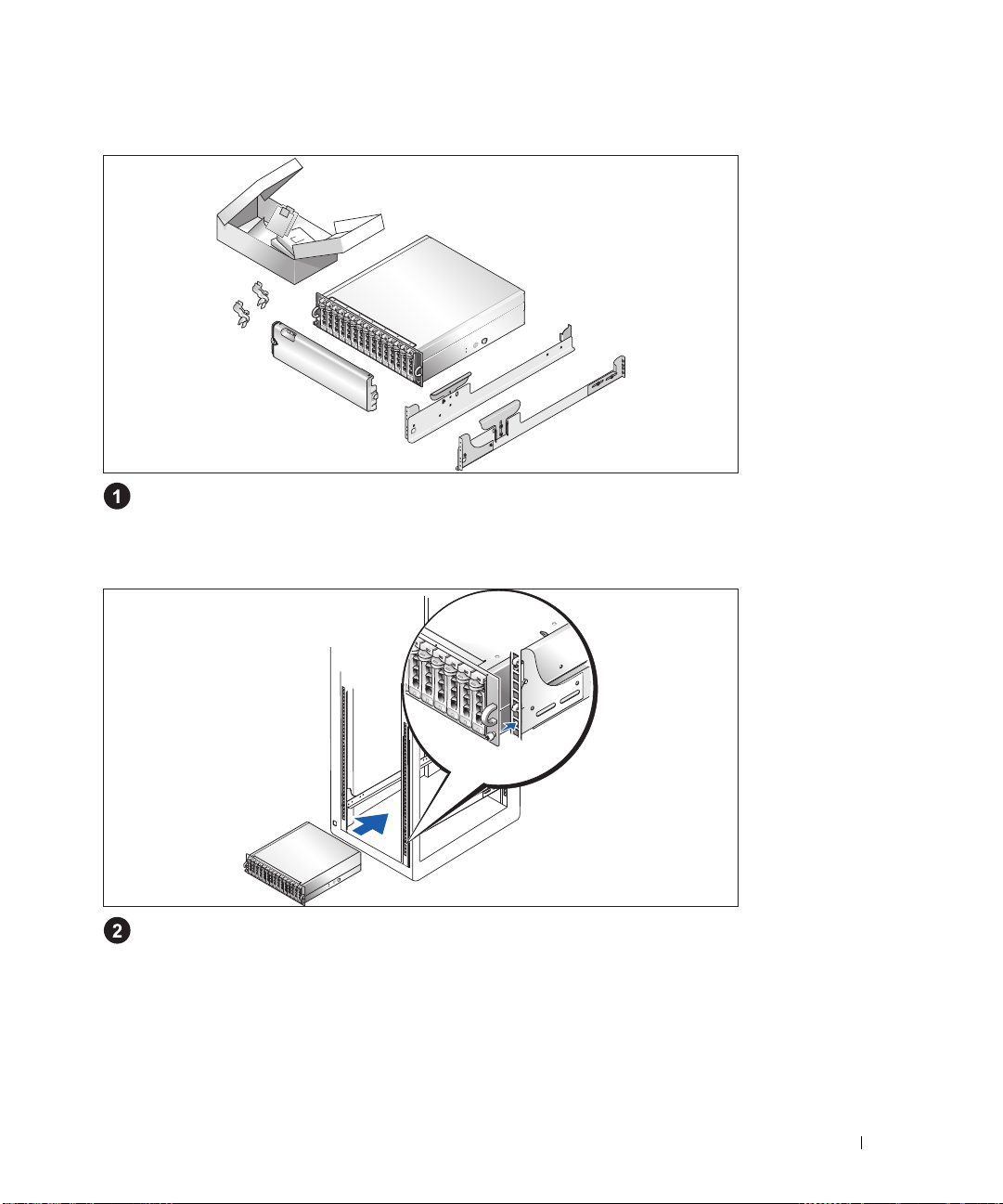
Unpacking the System
Unpack your system and identify each item.
Keep all shipping materials in case you need them later.
Installing the Rails and System in a Rack
Once you have read the "Safety Instructions" located in the rack installation documentation
for your system, install the rails and the system in the rack.
See your rack installation documentation for instructions on installing your system in a rack.
Getting Started With Your System 5
Page 8
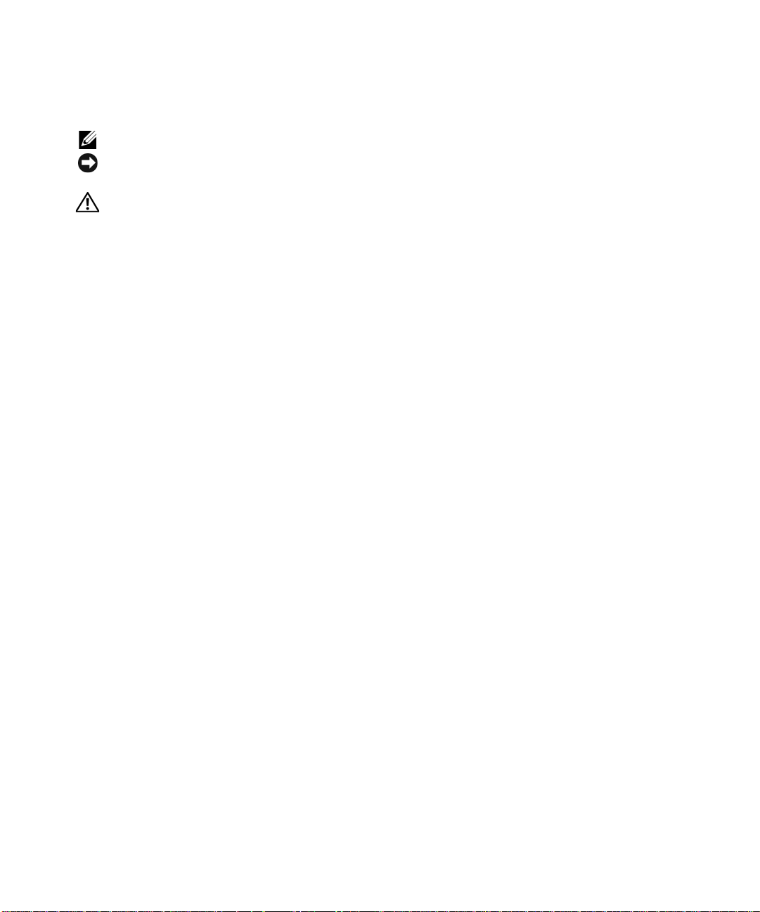
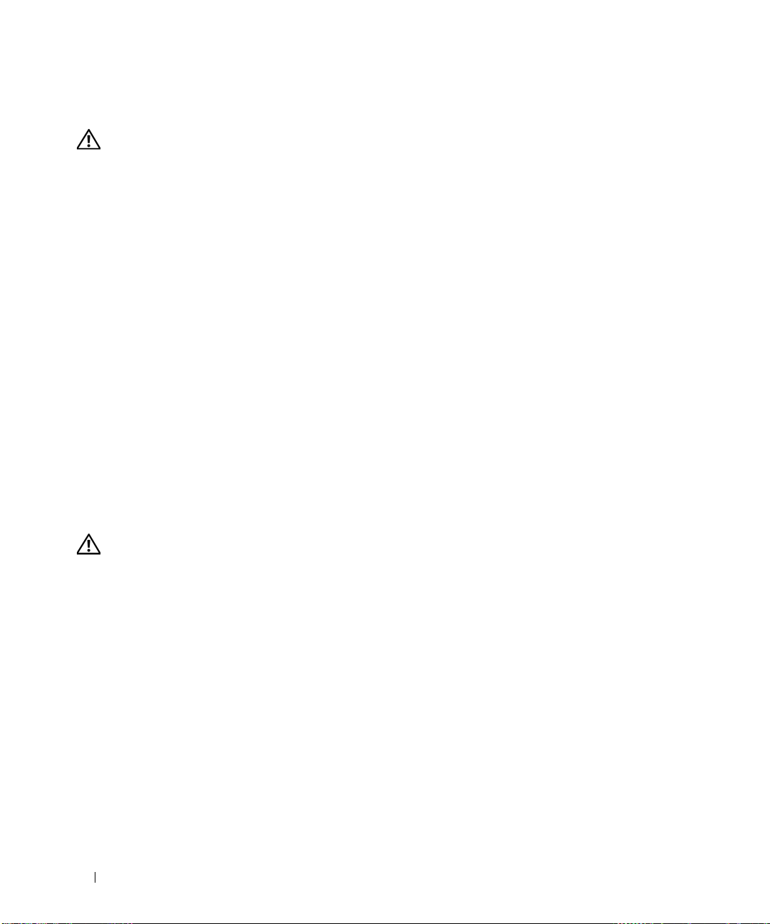
Connecting the Power Cables
Connect both power cables to the power supply/cooling fan modules.
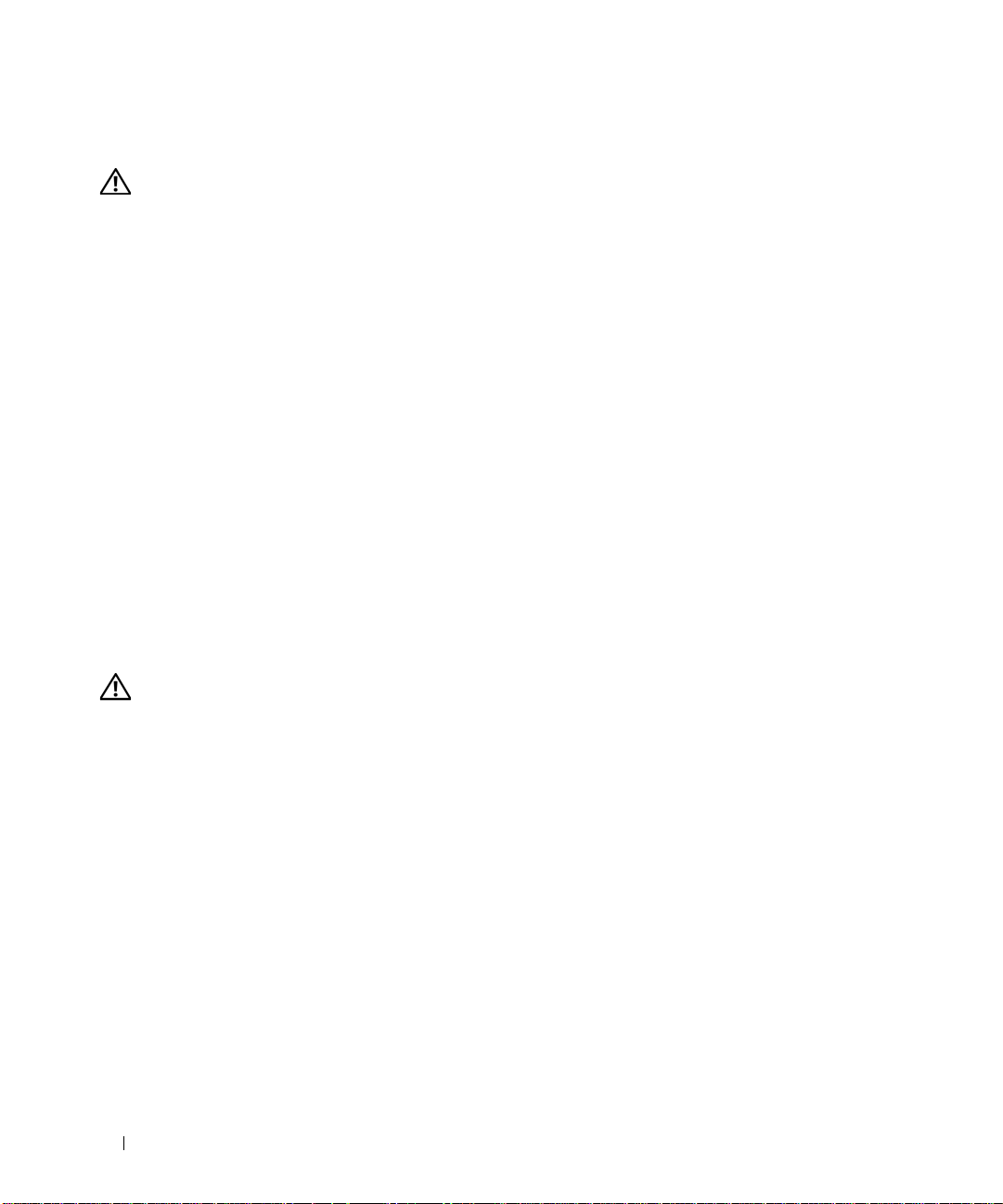
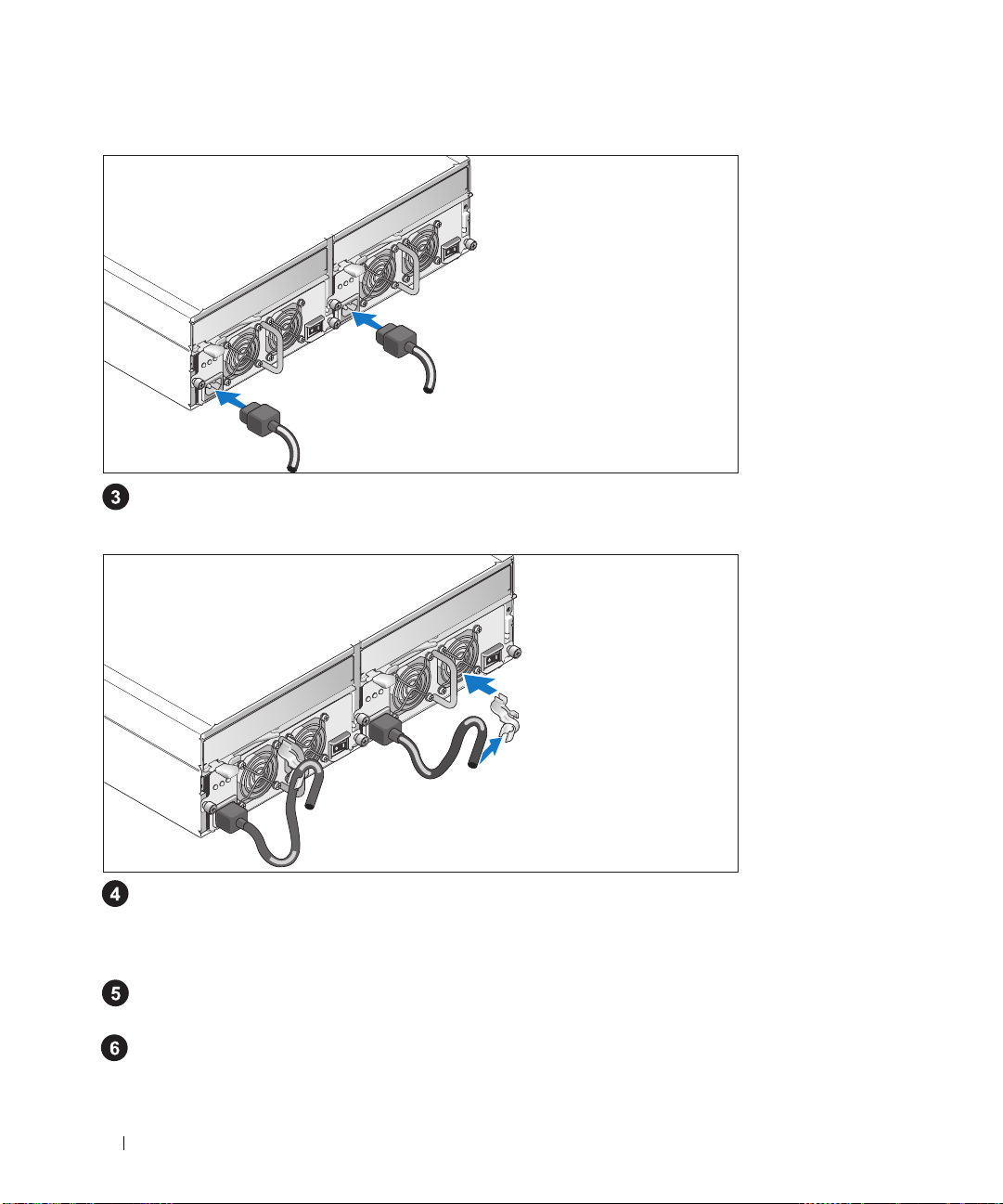
Attaching the Power Cord Retention Bracket
Attach the power cord retention bracket to the power supply loop by affixing the back clasp of the
bracket to the top of the loop and the middle clasp to the vertical middle of the loop. Attach the
system power cable to the bracket’s cable clasp. Repeat the procedure for the second power supply.
Plug the other end of the power cables into a grounded electrical outlet or a separate power source
an uninterruptible po
such as
Cable the RAID controller modules according to the instructions provided in the
Owner’s Manual
.
wer supply (UPS) or a power distribution unit (PDU).
Hardware
6 Getting Started With Your System
Page 9
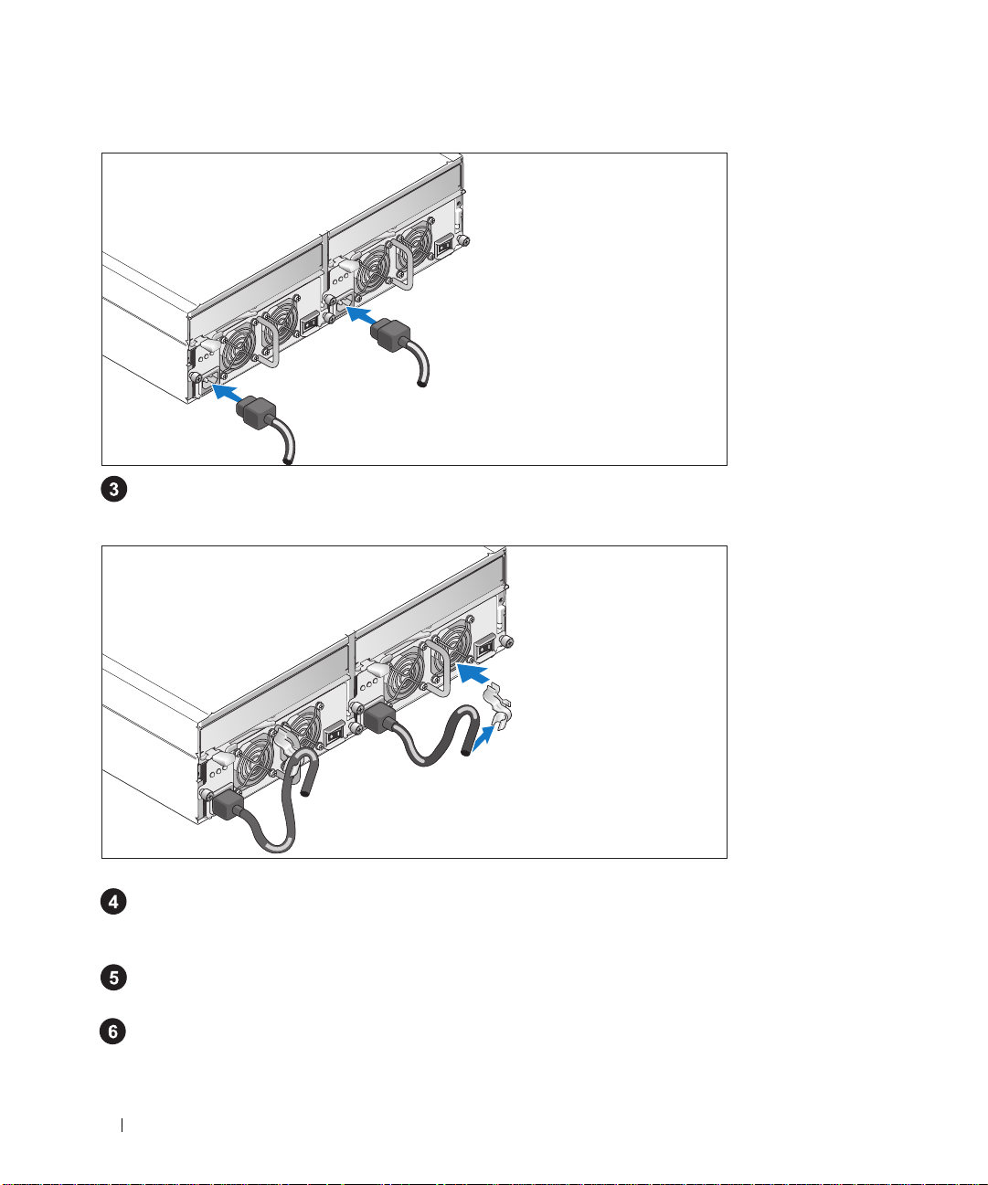
Turning on the System
Power on the system by turning on both power supply/cooling fan modules.
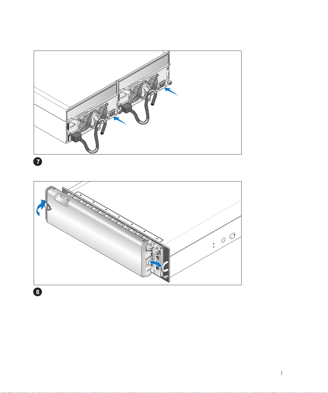
Installing the Bezel
Install the bezel (optional) by inserting the right edge of the bezel into the right front loop on the
system, and then pressing the left edge of the bezel to the system until the bezel snaps into place.
Getting Started With Your System 7
Page 10

Technical Specifications
Disks
Physical disks up to 15 1-inch-by-3.5-inch SAS and/or SATA II hot-plug physical
disks (3.0 Gbps). (See your system readme file for supported disk
capacities.)
RAID Controller Modules
RAID controllers
RAID Controller Back-Panel Connectors
SAS connectors (per RAID
controller)
Debug connector
(per RAID controller)
Ethernet connector
(per RAID controller)
Backplane Board
Connectors
Sensors 2 temperature sensors
LED Indicators
Front panel
Physical disk carrier
• 2 hot-pluggable active/active controllers
• 256 MB of cache per controller
• 1 temperature sensor per controller
• 1 SAS Port 0 "In" connector for connection to the host
• 1 SAS Port 1 "In" connector (if installed) for connection to an
additional host
• 1 SAS Port "Out" connector for expansion to an additional
enclosure
1 6-pin mini-DIN connector (debug port for Dell factory use only)
1 10/100 BASE-T connection for out-of-band management of the
enclosure
• 15 SAS physical-disk connectors
• 2 power supply/cooling fan module connectors
• 2 sets of RAID controller connectors (6 connectors each
controller)
• 1 control panel connector for front LEDs
• 1 two-color LED indicator for system status
• 2 single-color LED indicators (one for power; one nonfunctional)
• 1 single-color activity LED
• 1 two-color LED status indicator per disk
8 Getting Started With Your System
Page 11

RAID controllers The following single-color LEDs:
• Battery fault
• Cache active
• Controller fault
• Controller power
• Ethernet link
• Ethernet activity
• SAS Out fault
• SAS Out active
• SAS In fault (2 if additional In connector installed)
• SAS In active (2 if additional In connector installed)
Power supply/cooling fan
module
Power Supplies
Wattage 488 W maximum continuous; 550 W peak
Heat dissipation 200 W
Voltage 100–240 V rated (actual 90–264 V)
Frequency 47–63 Hz
Amperage 7.2 A at 100 V, 3.6 A at 200 V
Available Physical Disk Power (Per Slot)
Supported physical-disk power
consumption
Physical
Height 13.11 cm (5.16 inches)
Width 44.63 cm (17.57 inches)
Depth 48.01 cm (18.9 inches)
Weight (maximum
configuration)
3 LED status indicators for power supply status, power supply/fan
fault, and AC status
up to 1.3 A at +12 V
up to 1.5 A at +5 V
35.37 kg (78 lb)
Getting Started With Your System 9
Page 12

Environmental (Enclosure)
Temperature:
Operating
Storage
Relative humidity
Operating
Storage
Altitude
Operating
Storage
BTU per hour 1430
Environmental (Battery Backup Unit [BBU])
Maximum input power
Regulated output voltage
from BBU
Minimum retention time
(life expectancy)
Working temperature range
(dry bulb)
Working relative humidity
range
Storage temperature range
(dry bulb)
Transit temperature range
(dry bulb)
Storage and transit humidity
range
Storage and transit maximum
temperature gradient
Storage and transit maximum
humidity gradient
10° to 35°C (50° to 95°F)
–40° to 65°C (–40° to 149°F)
20% to 80% (noncondensing)
5% to 95% (noncondensing)
–16 to 3048 m (–50 to 10,000 ft)
–16 to 10,600 m (–50 to 35,000 ft)
• +12 VDC +/–5% at 1 A
• +3.3 VDC +/–5% at 150 mA
• Operating temperature range: 5° to 55°C (41° to 131°F)
• +2.5 VDC +/–3% at 20 mA to 120 mA
• Operating temperature range: 5° to 55°C (41° to 131°F)
72 hours for 256-MB DDR-I DIMM, 2.5 V at 120 mA
• 5° to 55°C (41° to 131°F)
• Maximum dry bulb temperature derated by 3.3°C (37.9°F)
per 1000 m (3281 ft) above 500 m (1640 ft)
5% to 90% noncondensing
• –10° to 45°C (14° to 113°F) for 3 months maximum
• Maximum dry bulb temperature derated by 3.3°C (37.9°F)
per 1000 m (3281 ft) above 500 m (1640 ft)
–20° to 60°C (–4° to 140°F) for 1 week maximum
5% to 95% relative humidity
1°C (33.8°F) per minute to a maximum of 20°C (68°F) per hour
30% relative humidity per hour
10 Getting Started With Your System
Page 13

Začínáme se systémem
www.dell.com | support.dell.com
Page 14
Poznámky, upozornění a varování
POZNÁMKA: POZNÁMKA označuje důležitou informaci, která vám pomůže při lepším využívání vašeho
systému.
UPOZORNĚNÍ: UPOZORNĚNÍ poukazuje na možnost poškození hardwaru nebo ztráty dat a poskytuje
návod, jak se danému problému vyhnout.
POZOR: Výstraha („POZOR“) poukazuje na riziko poškození majetku, poranění nebo smrtelného
úrazu.
____________________
Informace obsažené v tomto dokumentu podléhají změnám bez předchozího upozornění.
© 2005 Dell Inc. Všechna práva vyhrazena.
Reprodukce jakýmkoli způsobem bez písemného povolení společnosti Dell Computer Corporation je přísně zakázána.
Ochranné známky použité v tomto textu: Dell a logo DELL jsou ochranné známky společnosti Dell Inc.
V tomto dokumentu mohou být použity další ochranné známky a obchodní názvy odkazující na subjekty, kterým tyto známky či názvy patří,
nebo na jejich výrobky. Společnost Dell Inc. se zříká jakýchkoli vlastnických zájmů o jiné než vlastní ochranné známky a obchodní názvy.
Model AMP01
Duben 2010 P/N YD846 Rev. A01
Page 15

Systémové funkce
V této části jsou popsány hlavní hardwarové a softwarové funkce vašeho systému. Jsou v ní obsaženy
i informace o doplňujících dokumentech, které příp. potřebujete při instalaci systému, a informace k
odborné pomoci.
Hlavní funkce vašeho systému:
•
Úložný systém v účelně řešené konzolové konstrukci
•
Kapacita pro 15 sériově propojených pevných disků SCSI (SAS) 1 palce, hot-plug, 3,0 Gb/s a/nebo
SATA II (Serial Advanced Technology Attachment II)
•
SAS 5/E adaptér pro připojení úložného svazku k serveru (serverům)
POZNÁMKA: Bootování systému není podporováno z externího zařízení připojeného k
adaptéru SAS nebo SCSI, včetně SAS 5/E, PERC 5/E, PERC 4e/DC nebo PERC 4/DC.
Aktuální informaci k podpoře při bootování z externích zařízení naleznete na adrese
support.dell.com.
•
Záložní hot-plug napájecí zdroj a kombinované chladicí moduly pro snadnou údržbu
•
Dva moduly RAID řadičů (aktivní/aktivní) umožňující správu záložních dat a systému
•
Podpora až dvou zřetězených ukládacích svazků pro celkem 45 pevných disků
•
Konfigurace a monitorování prostřednictvím softwaru MD Storage Manager
•
Čtyři senzory pro sledování okolní provozní teploty
•
Záložní napájecí zdroj pro zajištění napájení paměti systému RAID řadiče (cache) v případě výpadku
napětí
•
Funkce vypnutí při přehřátí
•
Podpora širokého spektra serverů (Informace o podporovaných systémech naleznete v souboru
„readme“. Aktualizovaný soubor „readme“ naleznete na stránkách společnosti Dell na adrese
support.dell.com
.)
Začínáme se systémem 13
Page 16
Další užitečné informace
POZOR:
Informace o záruce je součástí tohoto dokumentu nebo je přiložena samostatně.
•
Pokyny pro instalaci do stojanu
systémem popisují instalaci vašeho systému do stojanu.
•
Uživatelská příručka k hardwaru
se systémem a instalaci nebo výměnu systémových komponent.
•
CD dodané se systémem obsahuje dokumentaci a nástroje pro konfiguraci a správu vašeho systému.
•
Poznámky a soubory „readme“ mohou být také součástí dodávky a obsahují poslední aktualizace k
systému nebo dokumentaci, příp. rozšířené technické materiály určené zkušeným uživatelům a technikům.
Informační příručka produktu
nebo
Příručka pro instalaci do stojanu
obsahuje informaci o funkcích systému a popisuje řešení problémů
obsahuje důležité bezpečnostní a právní informace.
dodané s vaším stojanovým
Odborná pomoc
Nerozumíte-li některému z postupů popsaných v této příručce nebo nepracuje-li systém podle očekávání,
nahlédněte do Uživatelské příručky k hardwaru.
Společnosti Dell rovněž nabízí trénink a certifikaci (Dell Enterprise Training and Certification), pro více
informací navštivte www.dell.com/training. Tato služba nemusí být nabízena ve všech regionech.
Instalace a konfigurace
POZOR: Před provedením následujícího postupu si pročtěte a postupujte podle následujících
bezpečnostních pokynů a důležitých předpisů uvedených v
V této části jsou popsány kroky, které je nutné provést při první instalaci vašeho systému.
Informační příručka produktu
.
14 Začínáme se systémem
Page 17
Rozbalení systému
Rozbalte systém a identifikujte jeho jednotlivé součásti.
Veškerý obalový materiál uschovejte pro případ pozdější potřeby.
Instalace kolejniček a systému do stojanu
Nejprve si přečtěte „Bezpečnostní pokyny“ uvedené v instalační dokumentaci stojanu a systému,
potom proveďte instalaci kolejniček a systém do stojanu.
Pokyny pro instalaci systému do stojanu naleznete v dokumentaci pro instalování stojanu.
Začínáme se systémem 15
Page 18

Připojení napájecích kabelů
Připojte oba napájecí kabely ke zdroji napájení a k modulům s chladicími ventilátory.
Umístění napájecích kabelů do retenčních svorek
Připevněte retenční svorku napájecího kabelu k fixačnímu oku tak, že zadní úchyt svorky připevníte
k horní části oka a střední úchyt ke svislému středu oka. Připevněte napájecí kabel systému do úchytu
kabelové svorky. Celý postup zopakujte u druhého napájecího kabelu.
Potom zasuňte druhý konec kabelu do uzemněné zásuvky ve zdi nebo ho připojte k samostatnému zdroji
UPS
napájení, např. k
(Uninterruptible Power Supply - zdroj nepřerušitelného napájení) nebo jednotce
rozvaděče (PDU).
Zapojte kabely modulů RAID řadičů podle pokynů uvedených v
Uživatelské příručce k hardwaru
16 Začínáme se systémem
.
Page 19

Zapnutí systému
Zapněte systém zapnutím obou napájecích zdrojů/modulů s chladicími ventilátory.
Instalace čelního krytu
Nainstalujte čelní kryt (volitelně) tak, že zasunete pravou hranu krytu do oka na pravé straně systému
anásledně zatlačíte levou hrany krytu směrem k systému, až čelní kryt zapadne do své pozice.
Začínáme se systémem 17
Page 20

Technická specifikace
Disky
Pevné disky až 15 pevných disků 1x3,5 palce SAS a/nebo SATA II, hot-plug,
3,0 Gb/s. (Viz soubor „readme“ vašeho systému s výčtem
podporovaných diskových kapacit.)
Moduly RAID řadičů
RAID řadiče
Konektory RAID řadičů na zadním panelu
SAS konektory
(pro každý RAID řadič)
Ladicí konektor
(pro každý RAID řadič)
Ethernet konektor
(pro každý RAID řadič)
Základní deska
Konektory
Senzory 2 teplotní senzory
LED indikátory
Čelní panel
Nosič pevného disku
•
2 aktivní/aktivní řadiče, hot-plug
•
256 MB cache pro každý řadič
•
1 teplotní senzor pro každý řadič
•
1 SAS port 0 „In“ konektor pro připojení k host systému
•
1 SAS port 1 „In“ konektor (je-li nainstalován) pro připojení k
dalšímu host systému
•
1 SAS port „Out“ konektor pro rozšíření o další svazek
1 6pinový mini-DIN konektor (ladicí port pouze pro tovární použití)
1 10/100 BASE-T připojení pro out-of-band správu svazku
•
15 konektorů pro SAS pevné disky
•
2 konektory napájení/modul s chladicími ventilátory
•
2 sady konektorů RAID řadičů (6 konektorů pro každý řadič)
•
1 konektor ovládacího panelu pro čelní LED indikátory
•
1 dvoubarevný LED indikátor stavu systému
•
2 jednobarevné LED indikátory (jeden pro napětí, jeden nefunkční)
•
1 jednobarevný LED indikátor aktivity
•
1 dvoubarevný LED indikátor stavu pro každý disk
18 Začínáme se systémem
Page 21

RAID řadiče Následující jednobarevné LED indikátory:
•
Selhání baterií
•
Cache aktivní
•
Selhání řadiče
•
Napětí řadiče
•
Ethernet propojení
•
Ethernet aktivita
•
SAS Out selhání
•
SAS Out aktivní
•
SAS In selhání (2, je-li nainstalován další „In“ konektor)
•
SAS In aktivní (2, je-li nainstalován další „In“ konektor)
Zdroj napájení/modul s
chladicími ventilátory
Napájení
Výkon 488 W max. průběžný; 550 W špičkový
Odvod tepla 200 W
Napětí 100 - 240 V jmenovité (efektivní 90 - 264 V)
Frekvence 47 - 63 Hz
Proud 7,2 A při 100 V, 3,6 A při 200 V
Spotřeba pevného disku (na slot)
Podporovaní spotřeba pevného
disku
Rozměry
Výška 13,11 cm (5,16 palců)
Šířka 44,63 cm (17,57 palců)
Hloubka 48,01 cm (18,9 palců)
Hmotnost (max. konfigurace) 35,37 kg (78 lb)
3 LED indikátory stavu pro stav napájecího zdroje, selhání
napájecího zdroje/ventilátoru a AC stav
až 1,3 A při +12 V
až 1,5 A při +5 V
Začínáme se systémem 19
Page 22

Prostředí (svazek)
Teplota:
provozní
skladovací
Relativní vlhkost
provozní
skladovací
Nadmořská výška
provozní
skladovací
BTU za hodinu 1430
Prostředí (záložní napájecí zdroj)
Max. příkon
Regulované výstupní napětí
ze zál. zdroje
Min. retenční čas
(předpokládaná životnost)
Rozsah pracovní teploty
(suchý teploměr)
Rozsah provozní relativní
vlhkosti
Rozsah skladovací teploty
(suchý teploměr)
Rozsah přepravní teploty
(suchý teploměr)
Rozsah skladovací a přepravní
vlhkosti vzduchu
Max. skladovací a přepravní
teplotní gradient
Max. skladovací a přepravní
vlhkostní gradient
10 až 35 °C (50 až 95 °F)
–40 až 65 °C (–40 až 149 °F)
20% až 80% (bez kondenzace)
5% až 95% (bez kondenzace)
–16 až 3048 m (–50 až 10000 stop)
–16 až 10600 m (–50 až 35000 stop)
•
•
•
•
•
72 hodin pro 256 MB DDR-I DIMM, 2,5 V při 120 mA
•
•
5% až 90% bez kondenzace
•
•
–20 až 60 °C (–4 až 140 °F) na max. 1 týden
5% až 95% relativní vlhkost
1 °C (33,8 °F) za minutu do max. 20 °C (68 °F) za hodinu
30% relativní vlhkosti za hodinu
+12 VDC +/–5% při 1 A
+3,3 VDC +/–5% při 150 mA
Rozsah provozní teploty: 5 až 55 °C (41 až 131 °F)
+2,5 VDC +/–3% při 20 mA až 120 mA
Rozsah provozní teploty: 5 až 55 °C (41 až 131 °F)
5 až 55 °C (41 až 131 °F)
Max. teplota se snižuje o 3,3 °C (37,9 °F) na každých 1000 m
(3281 stop) nad 500 m n.m. (1640 stop)
–10 až 45 °C (14 až 113° F) na max. 3 měsíce
Max. teplota se snižuje o 3,3 °C (37,9 °F) na každých 1000 m
(3281 stop) nad 500 m n.m. (1640 stop)
20 Začínáme se systémem
Page 23

Guide de mise
en route
www.dell.com | support.dell.com
Page 24
Remarques, avis et précautions
REMARQUE : une REMARQUE indique des informations importantes qui peuvent vous aider à mieux utiliser
votre système.
AVIS : un AVIS vous avertit d'un risque de dommage matériel ou de perte de données et vous indique comment éviter
le problème.
PRÉCAUTION : une PRÉCAUTION indique un risque potentiel d'endommagement du matériel, de blessure corporelle
ou de mort.
____________________
Les informations contenues dans ce document peuvent être modifiées sans préavis.
© 2005 Dell Inc. Tous droits réservés.
La reproduction de ce document de quelque manière que ce soit sans l'autorisation écrite de Dell Inc. est strictement interdite.
Marques utilisées dans ce document : Dell et le logo DELL sont des marques de Dell Inc.
Tous les autres noms de marques et marques commerciales utilisés dans ce document se rapportent aux sociétés propriétaires des marques et
des noms de ces produits. Dell Inc. décline tout intérêt dans l'utilisation des marques déposées et des noms de marques ne lui appartenant pas.
Modèle AMP01
Avril 2010 P/N YD846 Rev. A01
Page 25

Caractéristiques du système
Cette section décrit les principales caractéristiques du système sur le plan matériel et logiciel.
Elle contient également des informations sur les autres documents utiles à la configuration du
système et sur l'obtention d'assistance technique.
Les caractéristiques principales du système sont les suivantes :
• Conception optimisée pour un montage en rack
• Possibilité d'installer 15 disques durs SAS (Serial-attached SCSI) à 3,0 Gbps (disques de 1 pouce
enfichables à chaud) et/ou disques physiques SATA II (Serial Advanced Technology Attachment II)
• Carte SAS 5/E permettant de connecter la matrice de stockage à un ou plusieurs serveurs
REMARQUE : le démarrage du système à partir d'un périphérique externe connecté à une carte SAS ou
SCSI n'est pas pris en charge (cartes SAS 5/E, PERC 5/E, PERC 4e/DC et PERC 4/DC incluses). Voir le site
support.dell.com pour obtenir les informations les plus récentes concernant le démarrage à partir de
périphériques externes.
• Blocs d'alimentation et modules de refroidissement redondants et enfichables à chaud, combinés
en un seul bloc pour faciliter la maintenance du système
• Deux modules de contrôleur RAID de type actif/actif permettant une mise en redondance des
données et des fonctions de gestion du système
• Prise en charge d'un maximum de deux châssis reliés en série (soit un total de 45 disques
physiques)
• Configuration et contrôle via le logiciel MD Storage Manager
• Quatre capteurs assurant le contrôle des températures ambiantes
• Une unité de batterie de sauvegarde (BBU) permettant d'alimenter la mémoire système
du contrôleur RAID (mémoire cache) en cas de coupure de courant
• Fonction de coupure en cas de surchauffe
• Prise en charge d'une gamme de serveurs très étendue. Consultez le fichier readme du système
pour obtenir la liste des systèmes pris en charge. La version la plus récente de ce fichier se trouve
sur le site
support.dell.com
.
Guide de mise en route 23
Page 26
Autres informations utiles
PRÉCAUTION : le Guide d'informations sur le produit contient d'importantes informations se rapportant à la
sécurité et aux réglementations. Les informations sur la garantie se trouvent soit dans ce document, soit à part.
• Le document
la solution rack décrivent l'installation du système.
• Le document
les caractéristiques du système, ainsi que des instructions relatives au dépannage et à l'installation
ou au remplacement de composants.
• Le disque “Resource CD” fourni avec le système contient des documents et des outils relatifs à la
configuration et à la gestion du système.
• Des notes de version ou des fichiers lisez-moi (readme) sont parfois fournis ; ils contiennent des mises
à jour de dernière minute apportées au système ou à la documentation, ou des documents de référence
technique avancés destinés aux utilisateurs expérimentés ou aux techniciens.
Instructions d'installation du rack
Hardware Owner's Manual
(Manuel du propriétaire) contient des informations sur
ou le
Guide d'installation du rack
fournis avec
Obtention d'une assistance technique
Si vous ne comprenez pas une procédure décrite dans ce guide ou si le système ne réagit pas comme
prévu, consultez le document Hardware Owner's Manual (Manuel du propriétaire).
Des formations et certifications Dell Enterprise sont disponibles. Pour plus d'informations, consultez
le site www.dell.com/training. Ce service n'est disponible que dans certains pays.
Installation et configuration
PRÉCAUTION : avant d'exécuter la procédure suivante, lisez les consignes de sécurité et les informations
importantes sur les réglementations figurant dans le Guide d'informations sur le produit. Veillez à les respecter
scrupuleusement.
Cette section décrit les étapes à exécuter lors de la configuration initiale du système.
24 Guide de mise en route
Page 27

Déballage du système
Sortez le système de son emballage et identifiez chaque élément fourni.
Conservez les matériaux d'emballage au cas où vous en auriez besoin ultérieurement.
Installation des rails et du système dans un rack
Commencez par lire les consignes de sécurité qui se trouvent dans la documentation d'installation
du rack, puis installez les rails et le système dans le rack.
Consultez la documentation d'installation du rack pour obtenir les instructions appropriées.
Guide de mise en route 25
Page 28
Connexion des cordons d'alimentation
Branchez les deux cordons d'alimentation sur les modules d'alimentation et de ventilation.
Fixation du support du cordon d'alimentation
Installez le support du cordon d'alimentation. Pour ce faire, attachez le clip arrière sur le haut de la
poignée prévue à cet effet et le clip intermédiaire sur le milieu de la poignée. Ensuite, faites passer
le cordon d'alimentation dans le troisième clip du support. Recommencez cette procédure pour le
second bloc d'alimentation.
Branchez ensuite l'autre extrémité des cordons d'alimentation sur une prise de courant mise à la terre
ou sur une source d'alimentation autonome
Câblez les modules de contrôleur RAID en suivant les instructions du guide
(onduleur ou
unité de distribution de l'alimentation
Hardware Owner’s Manual
(Manuel du propriétaire).
26 Guide de mise en route
).
Page 29

Mise sous tension du système
Mettez le système sous tension en allumant les deux modules d'alimentation et de ventilation.
Installation du cadre
Pour installer le cadre en option, insérez sa partie droite dans la boucle de droite située à l'avant
du système, puis appuyez sur sa partie gauche jusqu'à ce que le cadre s'emboîte sur le système.
Guide de mise en route 27
Page 30

Caractéristiques techniques
Disques
Disques physiques Jusqu'à 15 disques physiques SAS et/ou SATA II enfichables à
chaud de 1 x 3,5 pouces (3,0 Gbps). Consultez le fichier Readme
pour savoir quelles sont les capacités prises en charge.
Modules de contrôleur RAID
Contrôleurs RAID
Connecteurs de contrôleur RAID sur le panneau arrière
Connecteurs SAS (pour chaque
contrôleur RAID)
Connecteur de débogage
(pour chaque contrôleur RAID)
Connecteur Ethernet (pour
chaque contrôleur RAID)
Carte de fond de panier
Connecteurs
Capteurs 2 capteurs de température
Voyants
Panneau avant
Support de disque physique
• 2 contrôleurs actif/actif, enfichables à chaud
• 256 Mo de mémoire cache par contrôleur
• 1 capteur de température par contrôleur
• 1 connecteur SAS “In” (Port 0) pour la connexion à l'hôte
• 1 connecteur SAS “In” (Port 1, s'il est installé) pour la connexion
à un hôte supplémentaire
• 1 connecteur SAS “OUT” pour l'ajout d'un châssis
supplémentaire
1 connecteur mini-DIN à 6 broches (utilisation en usine réservée
à Dell)
1 connexion 10/100 BASE-T pour la gestion hors bande du châssis
• 15 connecteurs de disques physiques SAS
• 2 connecteurs de modules d'alimentation et de ventilation
• 2 ensembles de connecteurs pour contrôleur RAID (6 connecteurs
pour chaque contrôleur)
• 1 connecteur de panneau de commande pour les voyants frontaux
• 1 voyant bicolore indiquant l'état du système
• 2 voyants monochromes (un voyant d'alimentation et un voyant
de panne)
• 1 voyant d'activité monochrome
• 1 voyant d'état bicolore par disque
28 Guide de mise en route
Page 31

Contrôleurs RAID Voyants monochromes :
• Pile défectueuse
• Mémoire cache active
• Panne du contrôleur
• Alimentation du contrôleur
• Liaison Ethernet
• Activité Ethernet
• Panne sur le port SAS “Out”
• Port SAS “Out” actif
• Panne sur le port SAS “In” (2 si le connecteur “In”
supplémentaire est installé)
• Port SAS “In” actif ((2 si le connecteur “In” supplémentaire
est installé)
Module d'alimentation
et de ventilation
Blocs d'alimentation
Puissance Puissance maximale de 488 W en continu ; puissance de pointe
Dissipation thermique 200 W
Tension Nominale : 100–240 V (réelle 90–264 V)
Fréquence 47-63 Hz
Intensité du courant 7,2 A à 100 V ; 3,6 A à 200 V
Alimentations disponibles pour les disques physiques (par logement)
Consommation prise en charge
pour les disques physiques
Caractéristiques physiques
Hauteur 13,11 cm (5,16 pouces)
Largeur 44,63 cm (17,57 pouces)
Profondeur 48,01 cm (18,9 pouces)
Poids (configuration maximale) 35,37 kg (78 livres)
3 voyants d'état (état du bloc d'alimentation, panne du module
d'alimentation/ventilation et état de l'alimentation en CA)
de 550 W
Jusqu'à 1,3 A à +12 V
Jusqu'à 1,5 A à +5 V
Guide de mise en route 29
Page 32

Environnement (châssis)
Température :
Fonctionnement
Stockage
Humidité relative
Fonctionnement
Stockage
Altitude
Fonctionnement
Stockage
BTU/h 1 430 (360 kcal/h)
Environnement (unité de batterie de sauvegarde [BBU])
Puissance d'entrée maximale
Tension de sortie régulée
de la BBU
Délai minimal de rétention 72 heures pour une barrette DIMM DDR-I de 256 Mo
Température de fonctionnement
(environnement sec)
Taux d'humidité relative
de l'environnement de
fonctionnement
Température de stockage
(environnement sec)
Température de transport
(environnement sec)
Taux d'humidité de
l'environnement de stockage
et de transport
Gradient thermique maximal
pour le stockage et le transport
Gradient d'humidité maximal
pour le stockage et le transport
De 10° à 35° C (50 à 95° F)
De -40° à 65° C (-40° à 149 °F)
De 20 à 80 % (sans condensation)
De 5 % à 95 % (sans condensation)
De -16 à 3 048 m (-50 à 10 000 pieds)
De -16 à 10 600 m (–50 à 35 000 pieds)
• +12 VCC +/–5% à 1 A
• +3,3 VCC +/–5% à 150 mA
• Température de fonctionnement : de 5° à 55°C (41° à 131°F)
• +2,5 VCC +/–3% (20 mA à 120 mA)
• Température de fonctionnement : de 5° à 55°C (41° à 131°F)
(2,5 V à 120 mA)
• de 5° à 55°C (41° à 131°F)
• Valeur nominale réduite de 3,3°C (37,9°F) tous les 1 000 m
(3 281 pieds) à partir de 500 m (1 640 pieds)
5% à 90% (sans condensation)
• de –10° à 45°C (14° à 113°F) pendant 3 mois maximum
• Valeur nominale réduite de 3,3°C (37,9°F) tous les 1 000 m
(3 281 pieds) à partir de 500 m (1 640 pieds)
De –20° à 60°C (–4° à 140°F) pendant 1 semaine maximum
De 5% à 95% d'humidité relative
De 1°C (33,8°F) par minute jusqu'à un maximum de 20°C (68°F)
par heure
30% d'humidité relative par heure
30 Guide de mise en route
Page 33

Erste Schritte
mit dem System
www.dell.com | support.dell.com
Page 34

Anmerkungen, Hinweise und Warnungen
ANMERKUNG: Ein HINWEIS enthält wichtige Informationen, mit deren Hilfe Sie Ihr System besser nutzen können.
HINWEIS: Ein HINWEIS warnt vor möglichen Beschädigungen der Hardware oder vor Datenverlust und zeigt auf,
wie derartige Probleme vermieden werden können.
VORSICHT: Hiermit werden Sie auf eine potentiell gefährliche Situation hingewiesen, die zu Sachschäden,
Verletzungen oder zum Tod führen könnte.
____________________
Irrtümer und technische Änderungen vorbehalten.
© 2005 Dell Inc. Alle Rechte vorbehalten.
Die Reproduktion dieses Dokuments in jeglicher Form ist ohne schriftliche Genehmigung von Dell Inc. streng verboten.
Marken in diesem Text: Dell und das DELL Logo sind Marken von Dell Inc.
Alle anderen in dieser Dokumentation genannten Marken und Handelsbezeichnungen sind Eigentum der jeweiligen Hersteller und Firmen.
Dell Inc. erhebt keinen Anspruch auf Marken und Handelsbezeichnungen mit Ausnahme der eigenen.
Modell AMP01
April 2010 P/N YD846 Rev. A01
Page 35

Systemmerkmale
In diesem Kapitel sind die wesentlichen Hardware- und Softwaremerkmale des Systems beschrieben.
Ferner erhalten Sie Informationen über weitere nützliche Dokumente, die zur Einrichtung des
Systems benötigt werden. Hier erfahren Sie auch, wie Sie technische Unterstützung erhalten
können.
Dies sind die wesentlichen Funktionsmerkmale des Systems:
• Effizientes Speichersystem mit Rackmontage
• Kapazität für 15 physische Festplatten, jeweils 1 Zoll, hot-plug-fähig, 3,0 Gb/s, SAS
(Serial-Attached SCSI) und/oder SATA II (Serial Advanced Technology Attachment II)
• SAS 5/E-Adapter zur Verbindung des Speicher-Arrays mit Servern
ANMERKUNG: Es wird kein Systemstart von einem externen Gerät an einem SAS- oder SCSI-Adapter
unterstützt, einschließlich SAS 5/E, PERC 5/E, PERC 4e/DC und PERC 4/DC. Unter support.dell.com
erhalten Sie aktuelle Informationen über das Starten von externen Geräten.
• Redundante hot-plug-fähige Netzteil- und Lüftermodule, zur vereinfachten Wartung kombiniert
• Zwei RAID-Controllermodule (aktiv/aktiv) zur redundanten Daten- und Systemverwaltung
• Unterstützung für bis zu zwei verkettete Speichergehäuse und damit insgesamt 45 physische
Laufwerke
• Konfiguration und Überwachung mit der Software MD Storage Manager
• Vier Sensoren zur Überwachung von Umgebungstemperaturen
• Batteriesicherungsmodul (BBU) zur Versorgung des RAID-Controller-Systemspeichers (Cache)
bei Stromausfall
• Funktion für Übertemperaturabschaltung
• Unterstützung für einen weiten Bereich von Servern. (Die unterstützten Server sind in der
readme-Datei zum System aufgeführt. Eine aktuelle Version der readme-Datei erhalten Sie
auf der Dell Website unter
support.dell.com
.)
Erste Schritte mit dem System 33
Page 36

Weitere nützliche Informationen
VORSICHT: Das Product Information Guide (Produktinformationshandbuch) enthält wichtige Informationen zu
Sicherheits- und Betriebsbestimmungen. Garantiebestimmungen können als separates Dokument beigelegt sein.
• In der zusammen mit der Rack-Lösung gelieferten
anleitung) bzw. im
Systems in einem Rack beschrieben.
• In der
• Die mitgelieferte Ressourcen-CD enthält Dokumentation und Dienstprogramme zum Konfigurieren
• Möglicherweise sind Versionshinweise oder Infodateien vorhanden – diese enthalten Aktualisierungen
Hardware Owner’s Manual
Systemfunktionen, zur Fehlerbehebung am System und zum Installieren oder Austauschen von
Systemkomponenten.
und Verwalten des Systems.
zum System oder zur Dokumentation bzw. detailliertes technisches Referenzmaterial für erfahrene
Benutzer oder Techniker.
Rack Installation Guide
(Hardware-Betriebsanleitung) erhalten Sie Informationen über
(Rack-Installationshandbuch) ist die Installation des
Rack Installation Instructions
(Rack-Installations-
Technische Unterstützung
Falls Sie einen Vorgang in diesem Handbuch nicht nachvollziehen können oder das System sich nicht
wie erwartet verhält, nehmen Sie das Hardware Owner’s Manual (Hardware-Benutzerhandbuch) zur
Hand.
Dell bietet Unternehmenstraining und Zertifizierung an. Weitere Informationen finden Sie unter
www.dell.com/training. Diese Dienstleistungen stehen unter Umständen nicht überall zur Verfügung.
Installation und Konfiguration
VORSICHT: Bevor Sie mit dem folgenden Vorgang beginnen, lesen und befolgen Sie die Sicherheitshinweise
und die Betriebsbestimmungen im Product Information Guide (Produktinformationshandbuch).
In diesem Abschnitt ist die erstmalige Einrichtung des Systems beschrieben.
34 Erste Schritte mit dem System
Page 37

Auspacken des Systems
Entnehmen Sie das System der Verpackung und identifizieren Sie die einzelnen Komponenten.
Bewahren Sie das Verpackungsmaterial für möglichen späteren Gebrauch auf.
Installation der Schienen und des Systems in einem Rack
Wenn Sie die Sicherheitshinweise in der Dokumentation zur Rack-Installation für das System
gelesen haben, können Sie die Schienen und das System im Rack installieren.
Wie Sie das System in einem Rack installieren, erfahren Sie in der Dokumentation zur RackInstallation.
Erste Schritte mit dem System 35
Page 38

Anschließen der Netzstromkabel
Verbinden Sie beide Netzstromkabel mit den Netzteil-/Lüftermodulen.
Anbringen der Netzkabel-Rückhalteklemme
Befestigen Sie die Netzkabel-Rückhalteklemme am Netzteilgriff, indem Sie den hinteren Haken
der Klemme an der Oberseite des Griffs fixieren und den mittleren Haken der Klemme am
vertikalen Mittelteil des Griffs. Befestigen Sie das Netzstromkabel des Systems an der Kabelklemme. Wiederholen Sie den Vorgang für das zweite Netzteil.
Verbinden Sie das andere Ende der Netzstromkabel jeweils mit einer geerdeten Steckdose oder
einer separaten Stromquelle wie etwa einer unterbrechungsfreien Stromversorgung (USV) oder
einem Stromverteiler (PDU).
Verkabeln Sie die RAID-Controllermodule nach den Anweisungen im Hardware Owner’s Manual
(Hardware-Benutzerhandbuch).
36 Erste Schritte mit dem System
Page 39

Einschalten des Systems
Aktivieren Sie die Stromversorgung des Systems, indem Sie beide Netzteil-/Lüftermodule
einschalten.
Anbringen der Frontverkleidung
Installieren Sie die Frontverkleidung (optional), indem Sie die rechte Kante der Frontverkleidung
in den Bogen vorn rechts am System einsetzen und dann die linke Seite der Frontverkleidung bis
zum Einrasten an das System drücken.
Erste Schritte mit dem System 37
Page 40

Technische Daten
Laufwerke
Physische Laufwerke Bis zu 15 physische Laufwerke (1 Zoll hoch, 3,5 Zoll breit,
hot-plug-fähig, SAS und/oder SATA II mit 3,0 Gb/s).
(Die unterstützten Laufwerkkapazitäten sind in der readmeDatei zum System verzeichnet.)
RAID-Controllermodule
RAID-Controller
Rückseitige Anschlüsse des RAID-Controllers
SAS-Anschlüsse
(je RAID-Controller)
Debug-Anschluss
(je RAID-Controller)
Ethernet-Anschluss
(je RAID-Controller)
Rückwandplatine
Anschlüsse
Sensoren 2 Temperatursensoren
LED-Anzeigen
Vorderes Bedienfeld
Laufwerkträger
• 2 hot-plug-fähige aktiv/aktiv-Controller
• 256 MB Cache je Controller
• 1 Temperatursensor je Controller
• Ein SAS Port 0-Eingangsanschluss („In“) zur Verbindung
mit dem Host
• Gegebenenfalls ein SAS Port 1-Eingangsanschluss („In“)
zur Verbindung mit einem weiteren Host
• Ein SAS-Ausgangsanschluss („Out“) zur Erweiterung durch
ein weiteres Gehäuse
Ein 6-poliger Mini-DIN-Anschluss (nur zur Nutzung durch
den Hersteller)
Ein 10/100 BASE-T-Anschluss für außerbandige Verwaltung
des Gehäuses
• 15 SAS-Anschlüsse für physische Laufwerke
• 2 Anschlüsse für Netzteil-/Lüftermodule
• 2 Sätze von RAID-Controlleranschlüssen
(6 Anschlüsse für jeden Controller)
• 1 Bedienfeldanschluss für LEDs auf der Vorderseite
• 1 zweifarbige LED-Anzeige für den Systemstatus
• 2 einfarbige LED-Anzeigen (eine für Stromversorgung,
eine ohne Funktion)
• 1 einfarbige Aktivitäts-LED
• 1 zweifarbige LED-Statusanzeige je Laufwerk
38 Erste Schritte mit dem System
Page 41

RAID-Controller Folgende einfarbige LED-Anzeigen:
• Batteriefehler
• Cache aktiv
• Controllerfehler
• Controllerstromversorgung
• Ethernet-Verbindung
• Ethernet-Aktivität
• SAS-Ausgangsfehler
• SAS-Ausgang aktiv
• SAS-Eingangsfehler (zwei Anzeigen, falls weiterer
Eingangsanschluss installiert ist)
• SAS-Eingang aktiv (zwei Anzeigen, falls weiterer
Eingangsanschluss installiert ist)
Netzteil-/Lüftermodul 3 LED-Statusanzeigen für Netzteilstatus, Netzteil-/Lüfterfehler
und Netzstromstatus
Netzteile
Leistung Maximal 488 W im Dauerbetrieb; Spitzenbelastung 550 W
Wärmeabgabe 200 W
Spannung Nennwert 100-240 V (tatsächlich 90-264 V)
Frequenz 47-63 Hz
Stromstärke 7,2 A bei 100 V; 3,6 A bei 200 V
Verfügbare Leistung für physische Laufwerke (je Schacht)
Unterstützte
Leistungsaufnahme von
physischen Laufwerken
Maße und Gewicht
Höhe 13,11 cm
Breite 44,63 cm
Tiefe 48,01 cm
Gewicht (maximale
Konfiguration)
Bis zu 1,3 A bei +12 V
Bis zu 1,5 A bei +5 V
35,37 kg
Erste Schritte mit dem System 39
Page 42

Betriebsbedingungen (Gehäuse)
Temperatur:
Während des Betriebs
Bei Lagerung
Relative Luftfeuchtigkeit
Während des Betriebs
Bei Lagerung
Höhe über NN
Während des Betriebs
Bei Lagerung
BTU pro Stunde 1430
Umgebungsbedingungen (Batteriesicherungsmodul [BBU])
Maximale Eingangsleistung
Geregelte Ausgangsspannung
von Batteriesicherungsmodul
(BBU)
Mindesthaltezeit
(Erwartungswert)
Betriebstemperatur (trocken)
Relative Luftfeuchtigkeit
bei Betrieb
Lagertemperatur (trocken)
Transporttemperatur (trocken) -20° bis 60 °C, maximal eine 1 Woche lang
Luftfeuchtigkeit bei Lagerung
und Transport
Maximaler Temperaturgradient
bei Lagerung und Transport
Maximaler Luftfeuchtegradient
bei Lagerung und Transport
10 °C bis 35 °C
-40° bis 65°C
20% bis 80% (nicht kondensierend)
5 bis 95 % (nicht kondensierend)
-16 bis 3048 m
-16 bis 10 600 m
• +12 VDC +/-5% bei 1 A
• +3,3 VDC +/-5% bei 150 mA
• Betriebstemperaturbereich: 5° bis 55 °C
• +2,5 VDC +/-3% bei 20 mA bis 120 mA
• Betriebstemperaturbereich: 5° bis 55 °C
72 Stunden für DDR-I-DIMM mit 256 MB, 2,5 V bei 120 mA
• 5° bis 55 °C
• Maximale Trockentemperatur sinkt um 3,3 °C je 1000 m
oberhalb 500 m
5% bis 90%, nicht kondensierend
• -10° bis 45 °C, maximal 3 Monate lang
• Maximale Trockentemperatur sinkt um 3,3 °C je 1000 m
oberhalb 500 m
5% bis 95% relative Luftfeuchtigkeit
1 °C pro Minute bis maximal 20 °C pro Stunde
30% relative Luftfeuchtigkeit pro Stunde
40 Erste Schritte mit dem System
Page 43

Τα πρώτα βήματα
Με το σύστημά σας
www.dell.com | support.dell.com
Page 44

Σημείωση, Ειδοποίηση και Προσοχή
ΣΗΜΕΙΩΣΗ: Η ένδειξη ΣΗΜΕΙΩΣΗ υποδεικνύει σημαντικές πληροφορίες που σας βοηθούν να
χρησιμοποιήσετε πιο σωστά το σύστημά σας.
ΕΙΔΟΠΟΙΗΣΗ: Η ένδειξη ΕΙΔΟΠΟΙΗΣΗ υποδεικνύει είτε πιθανή βλάβη του υλικού είτε απώλεια δεδομένων
και σας πληροφορεί πώς να αποφύγετε το πρόβλημα.
ΠΡΟΣΟΧΗ: Η ένδειξη ΠΡΟΣΟΧΗ υποδεικνύει την πιθανότητα υλικής ζημιάς, προσωπικού
τραυματισμού ή θανάτου.
____________________
Οι πληροφορίες που περιέχονται στο παρόν έγγραφο ενδέχεται να αλλάξουν χωρίς προηγούμενη ειδοποίηση.
© 2005 Dell Inc. Με επιφύλαξη κάθε νόμιμου δικαιώματος.
Απαγορεύεται αυστηρώς η αναπαραγωγή με οποιονδήποτε τρόπο χωρίς την έγγραφη άδεια της Dell Inc.
Εμπορικά σήματα που χρησιμοποιούνται σε αυτό το κείμενο: Η επωνυμία Dell και το λογότυπο DELL είναι εμπορικά σήματα της Dell Inc.
Στο παρόν έγγραφο ενδέχεται να χρησιμοποιούνται άλλα εμπορικ
διεκδικούν τα σήματα και τις ονομασίες ή για αναφορά στα προϊόντα τους. Η Dell Inc. αποποιείται οποιοδήποτε συμφέρον ιδιοκτησίας
από εμπορικά σήματα και εμπορικές ονομασίες εκτός από αυτά που έχει στην κατοχή της.
Μοντέλο AMP01
Απρίλιος 2010
P/N YD846 Rev. A01
ά σήματα και εμπορικές ονομασίες για αναφορά στις οντότητες που
Page 45

Χαρακτηριστικά συστήματος
Η ενότητα αυτή περιγράφει τα κύρια χαρακτηριστικά λογισμικού και υλικού του συστήματός σας.
Παρέχει επίσης πληροφορίες σχετικά με άλλα έγγραφα που ενδέχεται να χρειαστείτε για τη
ρύθμιση του συστήματός σας και σχετικά με τον τρόπο λήψης τεχνικής βοήθειας.
Τα κύρια χαρακτηριστικά του συστήματός σας περιλαμβάνουν:
•
Αποτελεσματικό σύστημα αποθήκευσης σχεδιασμένο για τοποθέτηση σε ράφι
•
Χωρητικότητα για 15 φυσικές μονάδες δίσκου 1-ίντσας, θερμής βυσμάτωσης, 3.0-Gbps,
σειριακής σύνδεσης SCSI (SAS) και / ή SATA II
•
Προσαρμογέας SAS 5/E για σύνδεση της διάταξης αποθήκευσης στο/στους διακομιστή/-ές
ΣΗΜΕΙΩΣΗ: Η εκκίνηση του συστήματος δεν υποστηρίζεται από εξωτερική συσκευή
συνδεδεμένη σε προσαρμογέα SAS ή SCSI, συμπεριλαμβανομένων των SAS 5/E, PERC 5/E,
PERC 4e/DC ή PERC 4/DC. Ανατρέξτε στην τοποθεσία support.dell.com για τις τελευταίες
πληροφορίες υποστήριξης σχετικά με την εκκίνηση από εξωτερικές συσκευές.
•
Εφεδρική, θερμής βυσμάτωσης, παροχή τροφοδοσίας και μονάδες ψύξης που συνδυάζονται
για δυνατότητα εύκολης επισκευής
•
Δύο active/active μονάδες ελεγκτή RAID για τη δυνατότητα εφεδρικής διαχείρισης συστήματος και
δεδομένων
•
Υποστήριξη για έως και δύο καλύμματα, αποθηκευμένα με αλυσιδωτή σύνδεση, για 45 φυσικές
μονάδες δίσκου στο σύνολο
•
Διαμόρφωση παραμέτρων και παρακολούθηση μέσω του λογισμικού διαχείρισης αποθήκευσης MD
•
Τέσ σ ε ρ ι ς αισθητήρες για την παρακολούθηση της θερμοκρασίας του περιβάλλοντος
•
Εφεδρική μονάδα μπαταρίας (BBU) για την τροφοδοσία της κρυφής μνήμης (cache) του συστήματος
του ελεγκτή RAID, σε περίπτωση διακοπής του ρεύματος
•
Δυνατότητα απενεργοποίησης σε περίπτωση υπέρβασης θερμοκρασίας
•
Υποστήριξη ευρείας γκάμας διακομιστών (Ανατρέξτε στο αρχείο readme του συστήματός σας για
τα συστήματα που υποστηρίζονται. Η προβολή του ενημερωμένου αρχείου readme των σημειώσεων
έκδοσης μπορεί να γίνει από την τοποθεσία υποστήριξης της Dell στο Web, στη διεύθυνση
support.dell.com
.)
Τα πρώτα βήματα με το σύστημά σας 43
Page 46

Άλλες πληροφορίες που ενδέχεται να χρειαστείτε
ΠΡΟΣΟΧΗ: Ο Οδηγός
ασφάλεια και τους ρυθμιστικούς κανόνες. Οι πληροφορίες για την εγγύηση ενδέχεται να
συμπεριλαμβάνονται μέσα σε αυτό το έγγραφο ή ως ξεχωριστό έγγραφο.
•
Οι
Οδηγίες εγκατάστασης σε ράφι
λύση σε ράφι περιγράφουν τον τρόπο εγκατάστασης τους συστήματός σας σε ράφι.
•
Το
Εγχειρίδιο κατόχου υλικού
και περιγράφει την αντιμετώπιση προβλημάτων του συστήματός σας και την εγκατάσταση ή την
αντικατάσταση συστατικών στοιχείων του συστήματος.
•
Το CD μέσων που συνοδεύει το σύστημά σας παρέχει τεκμηρίωση και εργαλεία για τη ρύθμιση
παραμέτρων και τη διαχείριση του συστήματός σας.
•
Σημειώσεις έκδοσης ή αρχεία readme ενδέχεται να περιλαμβάνονται για να παρέχουν τις τελευταίες
ενημερώσεις για το σύστημα, όπως επίσης τεκμηρίωση ή προχωρημένο υλικό αναφοράς για τεχνικά
θέματα που προορίζονται για έμπειρους χρήστες ή τεχνικούς.
πληροφοριών προϊόντος
ή ο
Οδηγός εγκατάστασης σε ράφι
παρέχει πληροφορίες σχετικά με τα χαρακτηριστικά του συστήματος
παρέχει σημαντικές πληροφορίες για την
που συνοδεύουν τη δική σας
Λήψη τεχνικής βοήθειας
Εάν δεν κατανοείτε μια διαδικασία του οδηγού αυτού ή αν το σύστημα δεν λειτουργεί με τον αναμενόμενο
τρόπο, ανατρέξτε στο Εγχειρίδιο κατόχου υλικού.
Είναι διαθέσιμη η Επιχειρηματική εκπαίδευση και πιστοποίηση της Dell. Για περισσότερες πληροφορίες,
ανατρέξτε στη διεύθυνση www.dell.com/training. Η υπηρεσία αυτή ενδέχεται να μην προσφέρεται σε όλες
τις τοποθεσίες.
Εγκατάσταση και ρύθμιση παραμέτρων
ΠΡΟΣΟΧΗ: Προτού πραγματοποιήσετε την παρακάτω διαδικασία, διαβάστε και ακολουθήστε
τις οδηγίες ασφαλείας και τους σημαντικούς ρυθμιστικούς κανόνες στον Οδηγό
προϊόντος.
Η ενότητα αυτή περιγράφει τα βήματα για την αρχική ρύθμιση των παραμέτρων του συστήματός σας.
44 Τα πρώτα βήματα με το σύστημά σας
πληροφοριών
Page 47

Άνοιγμα της συσκευασίας του συστήματος
Ανοίξτε τη συσκευασία του συστήματός σας και αναγνωρίστε κάθε αντικείμενο.
Φυλάξτε όλα τα υλικά της συσκευασίας για την περίπτωση που θα τα χρειαστείτε αργότερα.
Τοποθέτ η ση των ραγών και του συστήματος σε ράφι
Μόλις ολοκληρώσετε την ανάγνωση των “Οδηγιών ασφαλείας” που βρίσκονται στην τεκμηρίωση
εγκατάστασης σε ράφι για το σύστημά σας, τοποθετήστε τις ράγες και το σύστημα σε ράφι.
Για οδηγίες σχετικά με την εγκατάσταση του συστήματός σας σε ράφι, ανατρέξτε στην τεκμηρίωση
εγκατάστασης σε ράφι.
Τα πρώτα βήματα με το σύστημά σας 45
Page 48

Σύνδεση των καλωδίων τροφοδοσίας
Συνδέστε και τα δύο καλώδια τροφοδοσίας στις μονάδες παροχής τροφοδοσίας / ανεμιστήρων ψύξης.
Σύνδεση του στηρίγματος συγκράτησης του καλωδίου τροφοδοσίας
Συνδέστε το στήριγμα συγκράτησης του καλωδίου τροφοδοσίας στο βρόχο της παροχής τροφοδοσίας,
προσαρτώντας την πίσω αγκράφα στο επάνω μέρος του βρόχου και τη μεσαία αγκράφα στο κάθετο
κέντρο του βρόχου. Συνδέστε το καλώδιο τροφοδοσίας του συστήματος στην αγκράφα του καλωδίου
του στηρίγματος. Επαναλάβετε τη διαδικασία για τη δεύτερη παροχή τροφοδοσίας.
Τοποθετήστε την άλλη άκρη των καλωδίων τροφοδοσίας σε γειωμένο ρευματοδότη ή σε ξεχωριστή πηγή
ηλεκτρικού ρεύματος, όπως είναι ένα
σύστημα αδιάλειπτης
τροφοδοσίας (UPS) ή μια μονάδα διανομής
ρεύματος (PDU).
Τοποθετήστε τα καλώδια των μονάδων ελεγκτών RAID σύμφωνα με τις οδηγίες που παρέχονται στον
Εγχειρίδιο κατόχου υλικού
.
46 Τα πρώτα βήματα με το σύστημά σας
Page 49

Ενεργοποίηση του συστήματος
Ενεργοποιήστε το σύστημα ενεργοποιώντας και τις δύο μονάδες τροφοδοσίας / ανεμιστήρων ψύξης.
Τοποθέτ η ση της στεφάνης συγκράτησης
Τοποθετήστε τη στεφάνη συγκράτησης (προαιρετικά) εισάγοντας τη δεξιά πλευρά της στεφάνης στο
δεξί μπροστινό βρόχο στο σύστημα και στη συνέχεια, πατώντας την αριστερή πλευρά της στεφάνης
στο σύστημα, μέχρις ότου η στεφάνη να ασφαλίσει στη θέση της.
Τα πρώτα βήματα με το σύστημά σας 47
Page 50

Τεχνικές προδιαγραφές
Δίσκοι
Φυσικές μονάδες δίσκου έως και 15 φυσικές μονάδες δίσκου 1 έως 3,5 ιντσών, SAS και /
ή SATA II, θερμής βυσμάτωσης (3,0 Gbps). (Ανατρέξτε στο αρχείο
readme του συστήματός σας για τις χωρητικότητες των δίσκων που
υποστηρίζονται.)
Μονάδες ελεγκτών RAID
Ελεγκτές RAID
Συζευκτήρες πίσω μέρους για τον ελεγκτή RAID
Συζευκτήρες SAS (ανά ελεγκτή
RAID)
Συζευκτήρας αποσφαλμάτωσης
(ανά ελεγκτή RAID)
Συζευκτήρας ethernet
(ανά ελεγκτή RAID)
Κάτω επιφάνεια της πλάκας
Συζευκτήρες
Αισθητήρες 2 αισθητήρες θερμοκρασίας
Φωτεινές ενδείξεις LED
Μπροστινό μέρος
Κομιστής φυσικής
μονάδας δίσκου
•
2 ελεγκτές active/active θερμής βυσμάτωσης
•
256 MB κρυφής μνήμης (cache) ανά ελεγκτή
•
1 αισθητήρας θερμοκρασίας ανά ελεγκτή
•
1 συζευκτήρας SAS με θύρα 0 “In” για σύνδεση στην κεντρική
μονάδα
•
1 συζευκτήρας SAS με θύρα 1 “In” (αν έχει εγκατασταθεί)
για σύνδεση σε πρόσθετη κεντρική μονάδα
•
1 συζευκτήρας SAS με θύρα “Out” για επέκταση σε
πρόσθετο κάλυμμα
1 συζευκτήρας 6 ακίδων, τύπου mini-DIN (θύρα αποσφαλμάτωσης
για χρήση μόνο στο εργοστάσιο της Dell)
1 σύνδεση 10/100 BASE-T για εκτός περιοχής διαχείριση
του καλύμματος
•
15 συζευκτήρες φυσικών μονάδων δίσκου SAS
•
2 συζευκτήρες μονάδων τροφοδοσίας / ανεμιστήρων ψύξης
•
2 σετ συζευκτήρων μονάδων ελεγκτών RAID
(6 συζευκτήρες σε κάθε ελεγκτή)
•
1 συζευκτήρας πίνακα ελέγχου για τις μπροστινές φωτεινές
ενδείξεις LED
•
1 δίχρωμη φωτεινή ένδειξη LED για την κατάσταση του
συστήματος
•
2 μονόχρωμες φωτεινές ενδείξεις LED (μία για την τροφοδοσία
και μία για μη λειτουργία)
•
1 μονόχρωμη φωτεινή ένδειξη LED για τη δραστηριότητα
•
1 δίχρωμη φωτεινή ένδειξη LED για την κατάσταση για κάθε δίσκο
48 Τα πρώτα βήματα με το σύστημά σας
Page 51

Ελεγκτές RAID Οι ακόλουθες μονόχρωμες φωτεινές ενδείξεις LED:
•
Σφάλμα μπαταρίας
•
Ενεργή κρυφή μνήμη (cache)
•
Σφάλμα ελεγκτή
•
Τροφοδοσία ελεγκτή
•
Σύνδεση Ethernet
•
Δραστηριότητα Ethernet
•
Σφάλμα εξόδου SAS
•
Ενεργή έξοδος SAS
•
Σφάλμα στην είσοδο SAS (2 αν υπάρχει εγκατεστημένος πρόσθετος
συζευκτήρας εισόδου)
•
Ενεργή είσοδος SAS (2 αν υπάρχει εγκατεστημένος πρόσθετος
συζευκτήρας εισόδου)
Μονάδα τροφοδοσίας /
ανεμιστήρων ψύξης
Παροχές τροφοδοσίας
Ηλεκτρική ισχύς σε Watt 488 W μέγιστη συνεχόμενη. Κορυφή 550 W
Έκλυση θερμότητας 200 W
Τάσ η 100–240 V ονομαστική τιμή (πραγματική τιμή 90–264 V)
Συχνότητα 47–63 Hz
Ένταση ηλεκτρικού ρεύματος 7,2 A στα 100 V, 3,6 A στα 200 V
Διαθέσιμη τροφοδοσία φυσικής μονάδας δίσκου (ανά υποδοχή)
Υποστηριζ
κατανάλωση για τη φυσική
μονάδα δίσκου
Φυσικά χαρακτηριστικά
Ύψος 13,11 εκ. (5,16 ίντσες)
Μήκος 44,63 εκ. (17,57 ίντσες)
Πλάτος 48,01 εκ. (18,9 ίντσες)
Βάρος (μέγιστη διαμόρφωση) 35,37 κιλά (78 λίβρες)
όμενη ηλεκτρική
3 φωτεινές ενδείξεις LED για την κατάσταση της παροχής
τροφοδοσίας, για σφάλμα στην παροχή τροφοδοσίας ή στους
ανεμιστήρες και για την κατάσταση AC
έως και 1,3 A στα +12 V
έως και 1,5 A στα +5 V
Τα πρώτα βήματα με το σύστημά σας 49
Page 52

Χαρακτηριστικά περιβάλλοντος (Κάλυμμα)
Θερμοκρασία:
Λειτουργίας
Αποθήκευσης
Σχετική υγρασία
Λειτουργίας
Αποθήκευσης
Υψόμετρο
Λειτουργίας
Αποθήκευσης
BTU ανά ώρα 1430
Χαρακτηριστικά περιβάλλοντος (Εφεδρική μονάδα μπαταρίας [BBU])
Μέγιστη τροφοδοσία
εισόδου
Ρυθμισμένη τάση εξόδου από την
εφεδρική μονάδα μπαταρίας
Ελάχιστος χρόνος διατήρησης
(αναμενόμενη διάρκεια ζωής)
Εύρος θερμοκρασιών λειτουργίας
(μέτρηση με ξηρό θερμόμετρο)
Εύρος τιμών για τη σχετική
υγρασία λειτουργίας
Εύρος θερμοκρασιών
αποθήκευσης (μέτρηση
με ξηρό θερμόμετρο)
Εύρος θερμοκρασιών κατά τη
μεταφορά (μέτρηση με ξηρό
θερμόμετρο)
Εύρος τιμών για τη σχετική
υγρασία κατά την αποθήκευση
και τη μεταφορά
Μέγιστη βαθμίδα θερμοκρασίας
κατά την αποθήκευση και τη
μεταφορά
Μέγιστη βαθμίδα υγρασίας κατά
την απο
θήκευση και τη μεταφορά
10° έως 35°C (50° έως 95°F)
-40° έως 65°C (-40° έως 149°F)
20% έως 80% (χωρίς συμπύκνωση)
5% έως 95% (χωρίς συμπύκνωση)
–16 έως 3.048 μέτρα (–50 έως 10.000 πόδια)
–16 έως 10.600 μέτρα (–50 έως 35.000 πόδια)
•
+12 V DC +/–5% σε 1 A
•
+3,3 V DC +/–5% σε 150 mA
•
Εύρος θερμοκρασιών λειτουργίας: 5° έως 55°C (41° έως 131°F)
•
+2,5 V DC +/-3% σε 20 mA έως 120 mA
•
Εύρος θερμοκρασιών λειτουργίας: 5° έως 55°C (41° έως 131°F)
72 ώρες για 256-MB DDR-I DIMM, 2,5 V σε 120 mA
•
5° έως 55°C (41° έως 131°F)
•
Μέγιστη θερμοκρασία ξηρού θερμομέτρου μειωμένη ονομαστικά
κατά 3,3°C (37,9°F) ανά 1.000 μέτρα (3.281 πόδια) πάνω από τα
500 μέτρα (1.640 πόδια)
5% έως 90% χωρίς συμπύκνωση
•
-10° έως 45°C (14° έως 113°F) για μέγιστο διάστημα 3 μηνών
•
Μέγιστη θερμοκρασία ξηρού θερμομέτρου μειωμένη ονομαστικά
κατά 3,3°C (37,9°F) ανά 1.000 μέτρα (3.281 πόδια) πάνω από τα
500 μέτρα (1.640 πόδια)
-20° έως 60°C (-4° έως 140°F) για μέγιστο διάστημα 1 εβδομάδας
Σχετική υγρασία 5% έως 95%
1°C (33,8°F) ανά λεπτό έως τη μέγιστη τιμή των 20°C (68°F)
ανά ώρα
Σχετική υγρασία 30% ανά ώρα
50 Τα πρώτα βήματα με το σύστημά σας
Page 53

Rozpoczęcie pracy
z systemem
www.dell.com | support.dell.com
Page 54

Noty, uwagi i ostrzeżenia
UWAGA: UWAGA oznacza ważną informację, która pomoże lepiej wykorzystać system.
POUCZENIE: POUCZENIE wskazuje na możliwość uszkodzenia sprzętu lub utraty danych i informuje
o sposobie uniknięcia problemu.
OSTRZEŻENIE: PRZESTROGA wskazuje na możliwość zaistnienia sytuacji niebezpiecznej,
której skutkiem mogą być uszkodzenia sprzętu, obrażenia ciała lub śmierć.
____________________
Informacje zamieszczone w tym dokumencie mogą zostać zmienione bez uprzedzenia.
© 2005 Dell Inc. Wszystkie prawa zastrzeżone.
Zabrania się powielania w jakiejkolwiek postaci bez pisemnej zgody firmy Dell Inc.
Znaki towarowe użyte w niniejszym tekście: Dell i logo DELL są znakami towarowymi firmy Dell Inc.
W niniejszym tekście mogą występować inne znaki towarowe i nazwy handlowe odnoszące się zarówno do podmiotów mających prawo
do tych znaków i nazw, jak i do ich produktów. Dell Inc. nie zgłasza roszczeń do innych znaków i nazw handlowych poza swoimi.
Model AMP01
Kwiecień 2010
P/N YD846 Wersja A01
Page 55

Funkcje systemu
Ta sekcja opisuje najważniejsze cechy sprzętu i oprogramowania wchodzącego w skład systemu.
Dostarcza ona również informacji o innych dokumentach niezbędnych podczas konfiguracji systemu
oraz informuje o sposobie uzyskania pomocy technicznej.
Najważniejsze funkcje systemu obejmują:
•
System przechowywania danych do zamontowania na stabilnym stelażu.
•
Pojemność pozwalająca na zamontowanie 15 1 -calowych dysków twardych, 3.0-Gbps,
podłączanych szeregowo przez SCSI i/lub (SAS), z możliwością podłączenia w trakcie pracy
systemu.
•
Zasilacz SAS 5/E do podłączania układu przechowywania danych do serwera (ów).
UWAGA: Uruchamianie systemu nie jest obsługiwane z urządzenia zewnętrznego
podłączonego do zasilacza SAS lub SCSI, włącznie z SAS 5/E, PERC 5/E, PERC 4e/DC lub
PERC 4/DC. Odwiedź stronę internetową support.dell.com, aby uzyskać najaktualniejsze
informacje o uruchamianiu systemu z urządzeń zewnętrznych.
•
Nadmiarowy zasilacz do podłączania urządzeń podczas pracy systemu i moduły chłodzenia
umożliwiające łatwą obsługę systemu.
•
Dwa aktywne moduły kontrolera RAID do zarządzania nadmiarowymi danymi i systemem.
•
Obsługa aż do trzech połączonych łańcuchowo obudów systemu przechowywania danych mogących
pomieścić łącznie 45 dysków twardych.
•
Konfiguracja i monitorowanie za pomocą oprogramowania MD Storage Manager.
•
Cztery czujniki do monitorowania temperatury otoczenia.
•
Zapasowy zasilacz (BBU) gwarantujący zasilanie pamięci systemu (cache) kontrolera RAID
w przypadku przerwy w dostawie energii.
•
Funkcja wyłączania systemu w przypadku przekroczenia dopuszczalnej temperatury.
•
Obsługa szerokiej gamy serwerów (proszę zapoznać się z plikiem readme dostarczonym wraz z
systemem w celu uzyskania informacji o obsługiwanych systemach. Z aktualną wersją pliku readme
można się zapoznać na stronie internetowej firmy Dell
support.dell.com
.)
Rozpoczęcie pracy z systemem 53
Page 56

Inne przydatne informacje
Ostrzezenie: The
dotyczących bezpieczeństwa oraz informacji prawnych. Informacje dotyczące gwarancji
mogą zostać zamieszczone w tym dokumencie lub dostarczone jako oddzielny dokument.
•
Instrukcja instalacji stelażu
sposób instalacji systemu na stelażu.
•
Podręcznik użytkownika sprzętu
rozwiązywania problemów zaistniałych podczas użytkowania systemu oraz sposób instalacji lub
wymiany elementów systemu.
•
Płyta CD dołączona do systemu dostarcza dokumentacji i narzędzi niezbędnych do konfigurowania
systemu i zarządzania nim.
•
Informacje handlowe o wersji systemu lub pliki readme mogą być dołączone do systemu w celu
dostarczenia uaktualnień wprowadzonych do systemu lub dokumentacji w ostatniej chwili lub mogą
stanowić zaawansowany materiał referencyjny przeznaczony dla doświadczonych użytkowników lub
personelu technicznego.
Przewodnik z informacjami o produkcie
lub
Przewodnik instalacji stelażu
dostarcza informacji o funkcjach systemu i opisuje sposób
dostarczony wraz ze stelażem opisuje
dostarcza ważnych informacji
Uzyskiwanie pomocy technicznej
Jeżeli nie rozumieją Państwo procedur opisanych w tym przewodniku lub jeżeli system nie działa zgodnie
z oczekiwaniami, proszę zapoznać się z Podręcznikiem użytkownika sprzętu.
Dostępne są również szkolenia i certyfikaty firmy Dell Enterprise – proszę odwiedzić stronę internetową
www.dell.com/training w celu uzyskania dalszych informacji. Ta usługa może nie być dostępna we
wszystkich miejscach.
Instalacja i konfiguracja
Ostrzezenie: Przed wykonaniem poniższej procedury należy przeczytać i zastosować się do
instrukcji bezpieczeństwa oraz ważnych informacji prawnych zamieszczonych w
z informacjami o produkcie
Ta sekcja opisuje czynności, które mają być wykonane podczas konfigurowania systemu po raz pierwszy.
54 Rozpoczęcie pracy z systemem
.
Przewodnik
Page 57

Rozpakowanie systemu
Proszę rozpakować system i zidentyfikować jego poszczególne elementy.
Zachowaj wszystkie opakowania na wypadek potrzeby późniejszego ich wykorzystania.
Instalowanie prowadnic i systemu w stelażu
Po przeczytaniu “Instrukcji dotyczących bezpieczeństwa” przedstawionych w dokumentacji instalacyjnej
stelaża przeznaczonego dla systemu, proszę zainstalować na stelażu prowadnice i system.
W celu uzyskania instrukcji dotyczących instalowania systemu w stelażu, należy przejrzeć dokumentację
instalacji stelaża.
Rozpoczęcie pracy z systemem 55
Page 58

Podłączanie kabla zasilania
Podłączyć oba kable zasilania do zasilacza/modułów wentylatora.
Mocowanie wspornika podtrzymującego kabel zasilania
Podłączyć wspornik podtrzymujący kabel zasilania do pętli zasilacza mocując tylny zaczep wspornika
do górnej części pętli, a środkowy zaczep do środkowej części pętli usytuowanej pionowo. Podłączyć
kabel zasilania systemu do zacisku kabla na wsporniku. Powtórzyć tę samą procedurę dla drugiego
zasilacza.
Podłączyć drugą końcówkę tych kabli do uziemionego gniazdka zasilania lub oddzielnego źródła
zasilania
Proszę podłączyć kable do modułów kontrolera RAID zgodnie z instrukcjami zawartymi w
użytkownika sprzętu
np. do zasilania bezprzerwowego (UPS) lub
.
do jednostki rozdziału zasilania (PDU).
56 Rozpoczęcie pracy z systemem
Podręczniku
Page 59

Włączanie systemu
Podłączyć system do zasilania włączając zarówno zasilacz, jak i moduły wentylatora.
Instalowanie ramki
Zainstalować ramkę (opcjonalną) wsuwając jej prawą krawędź do prawej przedniej pętli na systemie,
anastępnie wciskając lewą krawędź ramki do systemu, aż do momentu, w którym ramka wskoczy
na miejsce.
Rozpoczęcie pracy z systemem 57
Page 60

Specyfikacja techniczna
Dyski
Dyski twarde aż do 15 1 -calowych dysków twardych, 3.0-Gbps, podłączanych szeregowo
przez SAS i/lub SATA II, z możliwością podłączenia w trakcie pracy
systemu. (Proszę zapoznać się z plikiem readme w celu uzyskania informacji
o obsługiwanych pojemnościach dysków).
Moduły kontrolera RAID
Kontrolery RAID
Złącza kontrolera RAID na panelu tylnym
Złącza SAS (dla każdego
kontrolera RAID)
Złącze do funkcji diagnostycznej/
usuwania błędów (dla każdego
kontrolera RAID)
Złącze sieci Ethernet (dla każdego
kontrolera RAID)
Tablica połączeń
Złącza
Czujniki 2 czujniki temperatury
Wskaźniki LED
Panel przedni
Nośnik dysku twardego
•
2 aktywne kontrolery, które można podłączyć podczas pracy systemu
•
256 MB pamięci systemowej (cache) dla każdego kontrolera
•
1 czujnik temperaturowy dla każdego kontrolera
•
1 złącze SAS (Port 0) "IN"(wejście) dla podłączenia do hosta.
•
1 złącze SAS (Port 1) "IN"(wejście) dla podłączenia do dodatkowego
hosta (jeżeli takowy jest zainstalowany).
•
1 złącze SAS dla portu "OUT"(wyjście) pozwalające na rozbudowę przy
użyciu dodatkowej obudowy.
1 6-pinowe złącze mini-DIN ( port funkcji diagnostycznej tylko do użytku
fabrycznego firmy Dell).
1 podłączenie 10/100 BASE-T dla zewnątrzpasmowego zarządzania
obudową.
•
15 złącz SAS dla dysków twardych
•
2 złącza dla zasilacza i modułu wentylatora
•
2 zestawy złącz dla kontrolera RAID (6 złącz dla każdego kontrolera)
•
1 złącze dla panela sterowania diod LED w przedniej części obudowy
•
1 dwukolorowy wskaźnik LED informujący o statusie systemu
•
2 jednokolorowe wskaźniki LED (jeden informujący o zasilaniu,
jeden nieużywany)
•
1 jednokolorowa dioda LED informująca o pracy systemu
•
1 dwukolorowy wskaźnik LED informujący o statusie każdego dysku
58 Rozpoczęcie pracy z systemem
Page 61

Kontrolery RAID Następujące jednokolorowe diody LED:
•
Awaria zasilacza
•
Pamięć systemu (cache) aktywna
•
Awaria kontrolera
•
Zasilanie kontrolera
•
Połączenie sieci Ethernet
•
Praca sieci Ethernet
•
Awaria wyjścia SAS
•
Wyjście SAS aktywne
•
Awaria wejścia SAS (2 jeżeli jest zainstalowane dodatkowe złącze dla
wejścia)
•
Wejście SAS aktywne (2 jeżeli jest zainstalowane dodatkowe złącze dla
wejścia)
Zasilacz/moduł wentylatora 3 wskaźniki statusu LED informujące o statusie zasilacza, awarii zasilacza /
wentylatora i statusie zasilania prądem zmiennym.
Zasilacze
Moc Maksymalna moc zasilania ciągłego – 488 W, wartość maksymalna - 550 W
Rozproszenie ciepła 200 W
Napięcie 100–240 V znamionowe (faktyczne 90–264 V)
Częstotliwość: 47–63 Hz
Natężenie 7.2 A przy 100 V, 3.6 A przy 200 V
Dostępne zasilanie dysku twardego (dla każdego slotu)
Zużycie mocy przez obsługiwane
dyski twarde
Aż do 1.3 A przy +12 V
Aż do 1,5 A przy +5 V
Cechy fizyczne
Wysokość 13.11 cm (5.16 cali)
Szerokość 44.63 cm (17.57 cali)
Głębokość 48.01 cm (18.9 cali)
Waga (konfiguracja maksymalna) 35.37 kg (78 funtów)
Rozpoczęcie pracy z systemem 59
Page 62

Warunki zewnętrzne (Obudowa)
Temperatura:
Podczas eksploatacji
Podczas przechowywania
Wilgotność względna
Podczas eksploatacji
Podczas przechowywania
Wysokość
Podczas eksploatacji
Podczas przechowywania
BTU na godzinę 1430
10° do 35°C (50° do 95°F)
–40° do 65°C (–40° do 149°F)
20% do 80% (przy braku kondensacji)
5% do 95% (przy braku kondensacji)
–16 do 3048 m (–50 do 10,000 stóp)
–16 do 10 600 m (–50 do 35,000 stóp)
Warunki zewnętrzne (Zasilacz zapasowy [BBU])
Maksymalna moc wejściowa
Regulowane napięcie wyjściowe z
zasilacza zapasowego (BBU)
Minimalny okres użytkowania
(żywotności)
Dopuszczalna temperatura podczas
pracy urządzenia
(sucha dioda/wskaźnik)
Dopuszczalna wilgotność względna
podczas pracy urządzenia
Dopuszczalna temperatura podczas
przechowywania
(sucha dioda/wskaźnik)
Dopuszczalna temperatura podczas
transportu (sucha dioda/wskaźnik)
Dopuszczalna wilgotność podczas
przechowywania i transportu
Maksymalny gradient temperatury
podczas przechowywania i transportu
Maksymalny gradient wilgotności
podczas przechowywania i transportu
•
+12 VDC +/–5% przy 1 A
•
+3,3 VDC +/–5% przy 150 mA
•
dopuszczalna temperatura podczas eksploatacji: 5° do 55°C
(41° do 131°F)
•
+2.5 VDC +/–3% at 20 mA do 120 mA
•
dopuszczalna temperatura podczas eksploatacji: 5° do 55°C
(41° do 131°F)
72 godziny dla 256-MB DDR-I DIMM, 2.5 V przy 120 mA
•
5° do 55°C (41° do 131°F)
•
Maksymalna temperatura suchej diody obniżona o 3.3°C (37.9°F) na każde
1000 m (3281 stóp) powyżej 500 m (1640 stóp)
5% do 90% (przy braku kondensacji)
•
–10° do 45°C (14° do 113°F) przez maksymalny okres 3 miesięcy
•
Maksymalna temperatura suchej diody obniżona o 3.3°C (37.9°F) na każde
1000 m (3281 stóp) powyżej 500 m (1640 stóp)
–20° do 60°C (–4° do 140°F) przez maksymalny okres 1 tygodnia
Wilgotność względna od 5% do 95%
1°C (33.8°F) na minutę do maksimum 20°C (68°F) na godzinę
30% wilgotności względnej na godzinę
60 Rozpoczęcie pracy z systemem
Page 63

Начало работы
с системой
www.dell.com | support.euro.dell.com
Page 64

Примечания, замечания и предупреждения
ПРИМЕЧАНИЕ: ПРИМЕЧАНИЕ содержит важную информацию, которая поможет использовать
систему более эффективно.
ВНИМАНИЕ: ЗАМЕЧАНИЕ указывает на возможность повреждения оборудования или потери
данных и объясняет, как этого избежать.
ПРЕДУПРЕЖДЕНИЕ: ПРЕДОСТЕРЕЖЕНИЕ указывает на потенциальную опасность
повреждения, получения травм или угрозу для жизни.
____________________
Информация в этом документе может быть изменена без предварительного уведомления.
© 2005 Dell Inc. Все права защищены.
Воспроизведение любой части данного документа любым способом без письменного разрешения корпорации Dell Inc. строго
воспрещается.
Товарные знаки, использованные в этом документе: Dell и логотип DELL являются товарными знаками корпорации Dell Inc.
Остальные товарные знаки и названия продуктов могут использоваться в этом руководстве для обозна
на товарные знаки и названия, или продуктов этих фирм. Корпорация Dell Inc. не заявляет прав ни на какие товарные знаки и названия,
кроме собственных.
Модель AMP01
Апрель 2010 г.
P/N YD846 Rev. A01
чения фирм, заявляющих права
Page 65

Характеристики системы
В этом разделе описываются основные компоненты аппаратного и программного обеспечения
системы. Кроме того, в нем содержится информация о других документах, которые могут быть
полезны при настройке системы, и о порядке получения технической поддержки.
Ниже перечислены основные характеристики системы.
•
Корпус системы хранения спроектирован в виде удобной монтажной стойки
•
Возможность установки 15 1-дюймовых жестких дисков с поддержкой горячей замены,
скоростью 3,0 Гбит/с и интерфейсом SCSI (SAS) и/или SATA II (Serial Advanced Technology
Attachment II)
•
Адаптер SAS 5/E для подключения массивов хранилищ к серверам
ПРИМЕЧАНИЕ: Не поддерживается загрузка системы с внешних устройств,
подключенных к адаптеру SAS или SCSI, включая SAS 5/E, PERC 5/E, PERC 4e/DC
или PERC 4/DC. Дополнительную информацию о поддержке загрузки системы с
внешних устройств можно найти на сайте support.dell.com.
•
Источник резервного электропитания с возможностью горячей замены и модули охлаждения,
объединенные в целях облегчения обслуживания
•
Два модуля RAID-контролеров активный/активный для избыточных данных и управления
системой
•
Поддержка до двух последовательно подключенных корпусов хранилищ с возможностью
подключения до 45 физических дисков
•
Конфигурирование и мониторинг с помощью программного обеспечения MD Storage Manager
•
Четыре датчика для мониторинга окружающей температуры
•
Модуль аварийного питания для поддержки системной памяти (кэш) RAID-контроллеров
в случае нарушения электроснабжения
•
Возможность отключения системы при перегреве
•
Поддержка широкого диапазона серверов. (Поддерживаемые серверы перечислены в
файле “Readme” к данной системе. Обновленный файл “Readme” можно найти на веб-сайте
технической поддержки корпорации Dell:
support.dell.com
.)
Начало работы с системой 63
Page 66

Прочая полезная информация
ПРЕДУПРЕЖДЕНИЕ: В документе
по продуктам) приведены важные сведения о безопасности, а также нормативные документы.
Гарантийная информация может включаться в состав данного документа или в отдельный
документ.
•
Документ
Guide
монтажа системы в стойку.
•
В документе
информация о характеристиках системы и описан порядок устранения неисправностей системы и
установки или замены ее компонентов.
•
Диск Resource CD, поставляемый вместе с системой, предоставляет документацию, а также
средства настройки системы и управления ею.
•
В комплект поставки могут включаться файлы с информацией о версии или файлы “Readme”
с описанием последних обновлений и изменений в системе или с дополнительной технической
информацией, предназначенной для опытных пользователей и обслуживающего персонала.
Rack Installation Instructions
(Руководство по установке в стойку), поставляемые со стойкой, описывают процедуру
Hardware Owner’s Manual
Product Information Guide
(Инструкции по установке в стойку) или
(Руководство пользователя оборудования) предоставляется
(Информационное руководство
Rack Installation
Получение технической поддержки
В случае непонимания приведенной в настоящем руководстве процедуры или если система не
работает должным образом, см. документ Hardware Owner’s Manual (Руководство пользователя
оборудования).
С программой обучения и сертификации корпорации Dell (Enterprise Training & Certification) можно
ознакомиться на сайте www.dell.com/training. Ус л у г и обучения и сертификации доступны не во
всех регионах.
Установка и конфигурирование
ПРЕДУПРЕЖДЕНИЕ: Перед выполнением описанных ниже процедур ознакомьтесь с
инструкциями по технике безопасности и важной нормативной информацией в документе
Информационное
В данном разделе описываются действия по первоначальной установке системы.
64 Начало работы с системой
руководство по
продуктам.
Page 67

Распаковка системы
Распакуйте систему и идентифицируйте каждый элемент.
Сохраните все поставляемые материалы, так как они могут понадобиться в дальнейшем.
Уста н овка направляющих кронштейнов и системы в стойку
После прочтения “Инструкций по технике безопасности”, представленных в документации
по установке системы в стойку, установите направляющие кронштейны и систему в стойку.
Инструкции по установке системы в стойку можно найти в документации по установке в стойку.
Начало работы с системой 65
Page 68

Подсоединение шнуров питания
Подключите шнура питания к модулям блока питания и охлаждающих вентиляторов.
Фиксация шнуров питания кронштейнами
Прикрепите кронштейн фиксации шнура питания к петле на блоке питания. Для этого
установите задний зажим кронштейна на верхней части петли, а нижний зажим – на боковой
ножке петли. Прикрепите шнур питания системы к кабельному зажиму кронштейна. Повторите
данную процедуру со вторым источником питания.
Подключите другой конец шнуров питания к заземленной розетке или отдельному источнику
питания, например,
Подключите кабели модулей RAID-контролеров в соответствии с инструкциями из руководства
пользователя оборудования (
к источнику бесперебойного
Hardware Owner’s Manual
питания или распределительному щиту питания.
).
66 Начало работы с системой
Page 69

Включение системы
Система запускается в результате включения модулей источника питания и охлаждающих
вентиляторов.
Уста н овка лицевой панели
Для установки (необязательной) лицевой панели вставьте ее правый край в правую петлю
на передней части системы, а затем нажмите на левый край лицевой панели до щелчка,
свидетельствующего о ее правильном положении в системе.
Начало работы с системой 67
Page 70

Технические спецификации
Диски
Физически диски до 15 1- и 3,5-дюймовых физических дисков с интерфейсом SAS и/или
SATA II и возможностью горячей замены (3,0 Гбит/с) . (Характеристики
поддерживаемых дисков перечислены в файле “Readme” к данной
системе.)
Модули RAID-котроллеров
RAID-контроллеры
Разъемы на задней панели RAID-контроллера
Разъемы SAS (на каждом RAIDконтроллере)
Отладочный разъем (на
каждом RAID-контроллере)
Разъем Ethernet (на каждом RAIDконтроллере)
Объединительная плата
Разъемы
Датчики 2 температурных датчика
Светодиодные индикаторы
Передняя панель
Индикаторы физических дисков
•
2 контроллера активный/активный с возможностью горячего
подключения
•
256 Мб кэш-памяти на каждом контроллере
•
по одному температурному датчику на каждом контроллере
•
1 входной разъем SAS-порта 0 для подключения к хосту
•
1 входной разъем SAS-порта 1 (если установлен) для подключения к
дополнительному хосту
•
1 выходной разъем SAS-порта для подключения к дополнительной
стойке
1 6-конта кт ный разъем mini-DIN (порт отладки только для фабричного
использования)
1 соединение 10/100 BASE-T для внеполосного управления стойкой
•
Разъемы для 15 физических дисков SAS
•
2 разъема для модулей источника питания и охлаждающих
вентиляторов
•
2 набора разъемов для RAID-контроллеров
(6 разъемов на каждом контроллере)
•
1 разъем панели управления для фронтальных светодиодных
индикаторов
•
1 двухцветный светодиодный индикатор состояния системы
•
2 одноцветных светодиодных индикатора (один для питания, другой
нефункциональный)
•
1 одноцветный светодиодный индикатор активности
•
2 двухцветных светодиодных индикатора состояния для каждого диска
68 Начало работы с системой
Page 71

RAID-контроллеры Следующие одноцветные светодиодные индикаторы:
•
Сбой батареи
•
Активный кэш
•
Сбой контроллера
•
Питание контроллера
•
Соединение Ethernet
•
Активность Ethernet
•
Сбой выходного разъема SAS
•
Активный выходной разъем SAS
•
Сбой входного разъема SAS (2, если установлен дополнительный
входной разъем)
•
Активный входной разъем SAS (2, если установлен дополнительный
входной разъем)
Модули источника питания и
охлаждающих вентиляторов
3 светодиодных индикатора состояния для индикации состояния
источника питания, сбоя источника питания или вентилятора
и состояния подачи переменного тока
Источники питания
Мощность в ваттах 488 Вт (продолжительная максимальная мощность); 550 Вт (пиковая
мощность)
Теплоотдача 200 Вт
Напряжение номинальное 100–240 В (реальное 90–264 В)
Частота 47 – 63 Гц
Сила тока 7,2 А при 100 В, 3,6 А при 200 В
Питание физических дисков (для каждого слота)
Поддерживаемый расход
электроэнергии физическими
дисками
до 1,3 А при +12 В
до 1,5 А при +5 В
Габариты
Высота 13,11 см
Ширина 44,63 см
Глубина 48,01 см
Вес (макс. конфигурация) 35,37 кг
Начало работы с системой 69
Page 72

Условия эксплуатации (стойка)
Температура:
Эксплуатация
Хранение
Относительная влажность
Эксплуатация
Хранение
Высота над уровнем моря
Эксплуатация
Хранение
BTU в час 1430
От 10° до 35°C
От -40° до 65°C
20 – 80 % (без конденсации)
5% – 95 % (без конденсации)
От -16 до 3 048 м
От -16 до 10 600 м
Условия эксплуатации (модуль аварийного питания)
Максимальная входная мощность
Регулируемое напряжение из
модуля аварийного питания
Минимальное время хранения
(срок службы)
Диапазон рабочих температур
(сухой термометр)
Рабочий диапазон относительной
влажности
Диапазон температур хранения
(сухой термометр)
Диапазон температур перевозки
(сухой термометр)
Допустимая влажность при
хранении и перевозке
Максимальный градиент
температуры при хранении
и перевозке
Максимальный градиент
влажности при хранении
и перевозке
•
+12 В +/–5% при постоянном токе 1 А
•
+3,3 В +/–5% при постоянном токе 150 мА
•
Диапазон рабочих температур: От 5° до 55°C
•
+2,5 В +/-3% при постоянном токе 20-120 мА
•
Диапазон рабочих температур: От 5° до 55°C
72 часов для DDR-I DIMM на 256-Мб, 2,5 В при 120 мА
•
От 5° до 55°C
•
Максимальная температура сухого термометра, сниженная на 3,3°C
на каждые 1000 м при высотах более 500 м.
5–90 % без конденсации
•
От –10° до 45°C не более 3 месяцев
•
Максимальная температура сухого термометра, сниженная на 3,3°C
на каждые 1000 м при высотах более 500 м.
От -20° до 60°C не более 1 недели
5-95% относительной влажности
1°C в минуту, но не более 20°C в час
30% относительной влажности в час
70 Начало работы с системой
Page 73

Procedimientos iniciales
con el sistema
www.dell.com | support.dell.com
Page 74

Notas, avisos y precauciones
NOTA: una NOTA proporciona información importante que le ayudará a utilizar mejor el sistema.
AVISO: un AVISO indica la posibilidad de daños en el hardware o la pérdida de datos, e informa de cómo evitar
el problema.
PRECAUCIÓN: un mensaje de PRECAUCIÓN indica el riesgo de daños materiales, lesiones o incluso la muerte.
____________________
La información contenida en este documento puede modificarse sin previo aviso.
© 2005 Dell Inc. Reservados todos los derechos.
Queda estrictamente prohibida la reproducción de este documento en cualquier forma sin la autorización por escrito de Dell Inc.
Marcas comerciales utilizadas en este texto: Dell y el logotipo de DELL son marcas comerciales de Dell Inc.
Otras marcas y otros nombres comerciales pueden utilizarse en este documento para hacer referencia a las entidades que los poseen
o a sus productos. Dell Inc. renuncia a cualquier interés sobre la propiedad de marcas y nombres comerciales que no sean los suyos.
Modelo AMP01
Abril de 2010 P/N YD846 Rev. A01
Page 75

Características del sistema
En esta sección se describen las principales características de hardware y software del sistema.
También se ofrece información sobre otros documentos que puede necesitar al instalar el sistema
y sobre cómo obtener asistencia técnica.
Las principales características del sistema son:
• Sistema de almacenamiento eficiente de montaje en rack
• Capacidad para 15 discos físicos SCSI conectados en serie (SAS) y/o SATA II (dispositivo conector
de tecnología avanzada serie II) de 3 Gbps, acoplamiento activo y 1 pulgada
• Adaptador SAS 5/E para conectar la matriz de almacenamiento al servidor o los servidores
NOTA: no es posible iniciar el sistema desde un dispositivo externo conectado a un adaptador SAS o
SCSI, incluido SAS 5/E, PERC 5/E, PERC 4e/DC o PERC 4/DC. Para obtener información sobre cómo iniciar
el sistema desde dispositivos externos, visite support.dell.com.
• Módulos redundantes de refrigeración y fuente de alimentación de acoplamiento activo para
facilitar las reparaciones
• Dos módulos de controladora RAID activo/activo para permitir la administración de sistemas
y datos redundantes
• Soporte para un máximo de dos alojamientos para almacenamiento conectados secuencialmente
para un total de 45 discos físicos
• Configuración y supervisión a través del software MD Storage Manager
• Cuatro sensores para supervisar la temperatura ambiente
• Unidad de reserva de batería (BBU) para alimentar la memoria de sistema (caché) de la controladora RAID en caso de interrumpirse la alimentación
• Capacidad de apagado del sistema en caso de exceso de temperatura
• Soporte para una amplia gama de servidores. Consulte el archivo Léame del sistema para ver una
relación de los sistemas admitidos. Encontrará un archivo Léame actualizado en la página Web
de Dell (
support.dell.com
).
Procedimientos iniciales con el sistema 73
Page 76

Otra información necesaria
PRECAUCIÓN: en la Guía de información del producto se proporciona información importante sobre seguridad
y normativas. La información de la garantía puede estar incluida en este documento o constar en un documento
aparte.
• En los documentos
el rack se describe cómo instalar el sistema en un rack.
• En el
• El CD de recursos que se suministra con el sistema proporciona documentación y herramientas
• Es posible que se incluyan notas de la versión o archivos Léame para proporcionar actualizaciones
Manual del propietario del hardware
sistema y se describe cómo solucionar problemas del sistema e instalar o reemplazar componentes
del sistema.
para configurar y administrar el sistema.
de última hora relativas al sistema o a la documentación, o material de consulta técnica avanzada
destinado a técnicos o usuarios experimentados.
Instrucciones de instalación del rack
se proporciona información sobre las características del
o
Guía de instalación del rack
incluidos con
Obtención de asistencia técnica
Si no comprende un procedimiento de esta guía o si el sistema no funciona del modo esperado,
consulte el Manual del propietario del hardware.
Tiene a su disposición el servicio de formación y certificación Dell para empresas. Para obtener más
información, visite www.dell.com/training. Es posible que este servicio no se ofrezca en todas las
regiones.
Instalación y configuración
PRECAUCIÓN: antes de realizar el procedimiento siguiente, lea y siga las instrucciones de seguridad
y la información importante sobre normativas incluidas en la Guía de información del producto.
En esta sección se describen los pasos para configurar el sistema por primera vez.
74 Procedimientos iniciales con el sistema
Page 77

Desembalaje del sistema
Desembale el sistema e identifique cada elemento.
Guarde el material de embalaje por si lo necesitara más adelante.
Instalación de los rieles y del sistema en un rack
Una vez que haya leído las “Instrucciones de seguridad” de la documentación del sistema relativa
a la instalación del rack , instale los rieles y el sistema en el rack.
Consulte la documentación de instalación del rack para obtener instrucciones sobre la instalación
del sistema en un rack.
Procedimientos iniciales con el sistema 75
Page 78

Conexión de los cables de alimentación
Conecte los dos cables de alimentación a los módulos de fuente de alimentación/ventilador
de refrigeración.
Fijación del soporte de retención del cable de alimentación
Sujete el soporte de retención del cable de alimentación al asa de la fuente de alimentación fijando
la abrazadera posterior del soporte a la parte superior del asa y la abrazadera intermedia a la mitad
vertical del asa. Fije el cable de alimentación del sistema a la abrazadera correspondiente del
soporte. Repita el procedimiento para la segunda fuente de alimentación.
Conecte el extremo opuesto de los cables de alimentación a una toma eléctrica con conexión a tierra
o a otra fuente de alimentación, como
de distribución de alimentación (PDU)
Cablee los módulos de controladora RAID según las instrucciones proporcionadas en el
del propietario del hardware
.
un sistema de alimentación
.
ininterrumpida (SAI) o una unidad
Manual
76 Procedimientos iniciales con el sistema
Page 79

Encendido del sistema
Encienda el sistema activando los dos módulos de fuente de alimentación/ventilador de refrigeración.
Instalación del embellecedor
Instale el embellecedor (opcional) insertando el extremo derecho del embellecedor en el asa frontal
derecha del sistema y luego presionando el extremo izquierdo del embellecedor contra el sistema
hasta que quede bien encajado.
Procedimientos iniciales con el sistema 77
Page 80

Especificaciones técnicas
Discos
Discos físicos Hasta 15 discos físicos SAS y/o SATA II de acoplamiento activo de
1 x 3,5 pulgadas (3 Gbps). Consulte el archivo Léame del sistema
para ver las capacidades de disco admitidas.
Módulos de controladora RAID
controladoras RAID
Conectores del panel posterior de la controladora RAID
Conectores SAS
(por controladora RAID)
Conector de depuración
(por controladora RAID)
Conector Ethernet
(por controladora RAID)
Tarjeta de plano posterior
Conectores
Sensores 2 sensores de temperatura
Indicadores LED
Panel frontal
Portaunidades de disco físico
• 2 controladoras activo/activo de acoplamiento activo
• 256 MB de caché por controladora
• 1 sensor de temperatura por controladora
• 1 conector de puerto 0 SAS “de entrada” para conexión al host
• 1 conector de puerto 1 SAS “de entrada” (si está instalado)
para conexión a un host adicional
• 1 conector de puerto SAS “de salida” para expansión a un
alojamiento adicional
1 miniconector DIN de 6 patas (puerto de depuración sólo para
uso en fábrica de Dell)
1 conexión 10/100 BASE-T para la administración fuera de banda
del alojamiento
• 15 conectores de disco físico SAS
• 2 conectores de módulo de fuente de alimentación/ventilador
de refrigeración
• 2 conjuntos de conectores de controladora RAID
(6 conectores cada controladora)
• 1 conector del panel de control para LED frontales
• 1 indicador LED de dos colores de estado del sistema
• 2 indicadores LED de un solo color (uno para alimentación;
otro para no funcionamiento)
• 1 LED de actividad de un solo color
• 1 indicador LED de estado de dos colores por disco
78 Procedimientos iniciales con el sistema
Page 81

Controladoras RAID Los siguientes LED de un solo color:
• Error de batería
• Caché activa
• Error de controladora
• Alimentación de controladora
• Enlace Ethernet
• Actividad Ethernet
• Error de SAS de salida
• SAS de salida activo
• Error de SAS de entrada (2 si hay instalado un conector
de entrada adicional)
• SAS de entrada activo (2 si hay instalado un conector de entrada
adicional)
Módulo de fuente de
alimentación/ventilador
de refrigeración
Fuentes de alimentación
Potencia 488 W continuos como máximo; pico de 550 W
Disipación de calor 200 W
Voltaje 100–240 V nominal (90–264 V real)
Frecuencia 47–63 Hz
Amperaje 7,2 A a 100 V; 3,6 A a 200 V
Alimentación del disco físico disponible (por ranura)
Consumo de energía admitido
para el disco físico
Características físicas
Altura 13,11 cm
Anchura 44,63 cm
Profundidad 48,01 cm
Peso (configuración máxima) 35,37 kg
3 indicadores LED de estado para el estado de la fuente de
alimentación, los fallos del ventilador o la fuente de alimentación
y el estado de CA
Hasta 1,3 A a +12 V
Hasta 1,5 A a +5 V
Procedimientos iniciales con el sistema 79
Page 82

Especificaciones ambientales (alojamiento)
Temperatura:
En funcionamiento
En almacenamiento
Humedad relativa
En funcionamiento
En almacenamiento
Altitud
En funcionamiento
En almacenamiento
BTU por hora 1430
Especificaciones ambientales (unidad de reserva de batería [BBU])
Alimentación de entrada
máxima
Voltaje de salida regulado
desde la BBU
Tiempo de retención mínimo
(expectativas de vida)
Intervalo de temperaturas
de trabajo (bulbo seco)
Intervalo de humedad relativa
de trabajo
Intervalo de temperaturas de
almacenamiento (bulbo seco)
Intervalo de temperaturas
de transporte (bulbo seco)
Intervalo de humedad en
almacenamiento y transporte
Gradiente de temperatura
máxima de almacenamiento
y transporte
Gradiente de humedad máxima
de almacenamiento y transporte
De 10 °C a 35 °C
De –40 °C a 65 °C
Del 20 al 80 % (sin condensación)
Del 5 al 95 % (sin condensación)
De –16 a 3 048 m
De –16 a 10 600 m
• +12 V CC +/–5 % a 1 A
• +3,3 V CC +/–5 % a 150 mA
• Intervalo de temperaturas de funcionamiento: De 5 °C a 55 °C
• +2,5 V CC +/–3 % a 20 mA hasta 120 mA
• Intervalo de temperaturas de funcionamiento: De 5 °C a 55 °C
72 horas para DIMM DDR-I de 256 MB, 2,5 V a 120 mA
• De 5 °C a 55 °C
• Temperatura máxima de bulbo seco reducida en 3,3 °C por cada
1 000 m por encima de 500 m
Del 5 al 90 % sin condensación
• De –10 °C a 45 °C durante 3 meses como máximo
• Temperatura máxima de bulbo seco reducida en 3,3 °C por cada
1 000 m por encima de 500 m
De –20 °C a 60 °C durante 1 semana como máximo
Humedad relativa del 5 % al 95 %
1 °C por minuto a un máximo de 20 °C por hora
Humedad relativa del 30 % por hora
80 Procedimientos iniciales con el sistema
Page 83

Sistem Başlangıç Kılavuzu
www.dell.com | support.dell.com
Page 84

Notlar, Bildirim Notları ve Dikkat Edilecek Noktalar
NOT:
NOT, sisteminizden daha iyi şekilde yararlanmanıza yardımcı olacak önemli bilgiler verir.
UYARI:
DİKKAT:
UYARI
, donanımda olabilecek hasarları ya da veri kaybını belirtir ve size, bu sorunun nasıl önleneceğini anlatır.
DİKKAT, olası maddi hasar, yaralanma veya ölüm tehlikesi anlamına gelir.
____________________
Bu belgedeki bilgiler önceden bildirilmeksizin değiştirilebilir.
© 2005 Dell Inc. Tüm hakları saklıdır.
Dell Inc.kuruluşunun yazılı izni olmadan herhangi bir şekilde çoğaltılması kesinlikle yasaktır.
Bu metinde kullanılan ticari markalar: Dell ve DELL logosu Dell Inc. kuruluşunun ticari markalarıdır.
Bu belgede, marka ve adların sahiplerine ya da ürünlerine atıfta bulunmak için başka ticari marka ve ticari adlar kullanılabilir. Dell Inc. kendine
ait olanların dışındaki ticari markalar ve ticari isimlerle ilgili hiçbir mülkiyet hakkı olmadığını beyan eder.
Model AMP01
Nisan 2010 P/N YD846 Rev. A01
Page 85

Sistem Özellikleri
Bu bölümde sisteminizin önemli donanım ve yazılım özellikleri açıklanmaktadır. Bu bölüm ayrıca
sisteminizi kurma veya teknik yardım alma konularında ihtiyaç duyabileceğiniz diğer belgeler hakkında
da bilgi sunmaktadır.
Sisteminizin önemli özellikleri şunlardır:
•
Verimli, raf montajı tasarımlı depolama sistemi
•
15 adet 1 inç, çalışırken çıkarılıp takılabilen, 3,0 Gbps, seri bağlantılı SCSI (SAS) ve/veya Seri
Gelişmiş Teknoloji Bağlantısı II (SATA II) fiziksel disk kapasitesi
•
Depolama dizisini sunuculara bağlamak için SAS 5/E adaptörü
NOT:
Sistem önyüklemesi SAS 5/E, PERC 5/E, PERC 4e/DC veya PERC 4/DC dahil bir SAS veya
SCSI adaptörüne bağlı harici bir aygıttan desteklenir. Harici aygıtlardan önyükleme hakkında en son
destek bilgileri için bkz.
•
Kolayca hizmet verebilmek için bir araya getirilmiş yedekli, çalışırken çıkarılıp takılabilen güç
kaynağı ve soğutma modülleri
•
Yedek veri ve sistem yönetimi ve özelliği için iki adet etkin/etkin RAID denetleyicisi modülleri
•
Toplam 45 fiziksel diske yönelik birbirine bağlanabilir iki depolama kasası için destek
•
MD Storage Manager yazılımı yoluyla yapılandırma ve izleme
•
Ortam sıcaklıklarını izlemek için dört sensör
•
RAID denetleyicisi sistem belleğine (önbellek) güç kesintisi durumunda güç sağlayan pil yedekleme
birimi (BBU)
•
Aşırı sıcaklıkta kapanma özelliği
•
Geniş bir aralıktaki sunucular için destek (Desteklenen sistemler için sisteminizin benioku dosyasına
bakın. Güncelleştirilmiş bir benioku dosyasını
bulabilirsiniz)
support.dell.com
.
support.dell.com
adresindeki Dell web sitesinde
Sistem Başlangıç Kılavuzu
83
Page 86

İhtiyacınız Olabilecek Diğer Bilgiler
UYARI:
edilmiş veya ayrı bir belge olarak eklenmiş olabilir.
•
Sisteminizle birlikte verilen
kuracağınızı açıklar.
•
Donanım Kullanıcı El Kitabı
sistem bileşenlerinin yüklenmesi ve değiştirilmesi işlemlerinin nasıl yapılacağını anlatmaktadır.
•
Sisteminizle birlikte verilen Kaynak CD'si sisteminizi yapılandırma ve yönetmeye yönelik belgeler ve
araçlar sunar.
•
Sistem için son dakika güncellemeleri ya da deneyimli kullanıcılar veya teknisyenler için tasarlanmış
belgeler veya teknik başvuru malzemesi sunmak üzere sürüm notları ve benioku dosyaları eklenmiş
olabilir.
Ürün Bilgileri Kılavuzu
önemli güvenlik ve tescil bilgilerini sunar. Garanti bilgileri bu belgeye dahil
Rafa Montaj Yönergeleri
sistem özellikleri üzerine bilgiler içermekte ve sistemde sorun giderme,
veya
Rafa Montaj Kılavuzu
sisteminizi bir rafa nasıl
Teknik Yardım Alma
Bu kılavuzdaki bir prosedürü anlamazsanız veya sistem beklediğiniz gibi çalışmazsa bkz. Donanım
Kullanıcı El Kitabı.
Dell Kurumsal Eğitim ve Sertifikasyon hizmetinizdedir; daha fazla bilgi için bkz. www.dell.com/training.
Bu hizmet tüm bölgelerde sunulmamaktadır.
Kurulum ve Yapılandırma
UYARI:
düzenleyici bilgileri okuyup izleyin.
Bu bölümde, sisteminiz ilk kez kurulurken yapmanız gereken işlemler anlatılmaktadır.
84
Aşağıdaki yordamı uygulamadan önce
Sistem Başlangıç Kılavuzu
Ürün Bilgi Kılavuzu
'ndaki güvenlik yönergelerini ve önemli
Page 87

Sistemi Paketinden Çıkarma
Sisteminizi paketinden çıkarın ve tüm parçaların tamam olup olmadığını kontrol edin.
İleride ihtiyacınız olması ihtimaline karşı, tüm kutuları saklayın.
Rayları ve Sistemi Rafa Monte Etme
Sisteminizin raf montaj belgelerinde bulunan "Güvenlik Yönergeleri" ni okuduktan sonra rayları ve
sistemi rafa monte edin.
Sisteminizi rafa monte etme ile ilgili yönergeler için rafa montaj belgelerine bakın.
Sistem Başlangıç Kılavuzu
85
Page 88

Güç Kablolarını Bağlama
İki güç kablosunu da güç kaynağı/soğutma fanı modüllerine takın.
Güç Kablosu Sabitleme Desteğini Takma
86
Güç kablosu sabitleme desteğini, desteğin arka çengelini ilmeğin üstüne, orta çengelini ise ilmeğin
dikey ortasına sabitleyerek güç kaynağı ilmeğine takın. Sistemin güç kablosunu desteğin kablo
çengeline takın. İkinci güç kaynağı için yordamı tekrarlayın.
Güç kablosunun diğer ucunu topraklı bir elektrik prizine ya da kesintisiz güç kaynağı (UPS) veya güç
dağıtım birimi (PDU) gibi ayrı
Donanım Kullanıcı El Kitabı
bir güç kaynağına takın.
'nda sağlanan yönergelere göre RAID denetleyicisi modüllerine kablo
döşeyin.
Sistem Başlangıç Kılavuzu
Page 89

Sistemi Açma
İki güç kaynağı/soğutma fanı modülünü de açarak sisteme güç verin.
Çerçeveyi Takma
Çerçeveyi (isteğe bağlı) çerçevenin sağ kenarını sistemdeki sağ ön halkaya takıp ardından çerçevenin sol
kenarını, çerçeve yerine oturuncaya kadar sisteme doğru bastırarak takın.
Sistem Başlangıç Kılavuzu
87
Page 90

Teknik Özellikler
Diskler
Fiziksel diskler en fazla 15 adet 1 inç/3,5 inç SAS ve/veya SATA II çalışırken
çıkarılıp takılabilen fiziksel disk (3,0 Gbps). (Desteklenen disk
kapasiteleri için sistem benioku dosyanıza bakın.)
RAID Denetleyicisi Modülleri
RAID denetleyicileri
RAID Denetleyicisi Arka Panel Konektörleri
SAS konektörleri (RAID
denetleyicisi başına)
Hata ayıklama konektörü (RAID
denetleyicisi başına)
Ethernet ayıklama konektörü
(RAID denetleyicisi başına)
Arka Panel Kartı
Konnektörler
Algılayıcılar 2 adet sıcaklık algılayıcısı
LED Göstergeler
Ön panel
Fiziksel disk taşıyıcısı
•
Çalışırken çıkarılıp takılabilen 2 adet etkin/etkin denetleyici
•
Denetleyici başına 256 MB önbellek
•
Denetleyici başına 1 adet sıcaklık sensörü
•
Ana bilgisayara bağlantı için 1 adet SAS Port 0 "Gırış " konektörü
•
Ek bir ana bilgisayara bağlantı için 1 adet SAS Port 1 "Giriş"
konektörü (takılıysa)
•
Ek bir kasaya genişletme için 1 adet SAS "Çikiş " konektörü
1 adet 6 pimli mini DIN konektörü (yalnızca Dell fabrika kullanımı
için hata ayıklama bağlantı noktası)
Kasanın bant dışı yönetimi için 1 adet 10/100 BASE-T bağlantısı
•
15 adet SAS fiziksel disk konektörü
•
2 adet güç kaynağı/soğutma fanı konektörü
•
2 takım RAID denetleyicisi konektörü (her denetleyiciye
6 konektör)
•
Ön LED'ler için 1 adet kontrol paneli
•
Sistem durumu için 1 adet iki renkli LED gösterge
•
2 adet tek renkli LED göstergesi (biri güç için; biri işlevsiz)
•
1 adet tek renkli etkinlik LED'i
•
Disk başına 1adet iki renkli LED durum göstergesi
88
Sistem Başlangıç Kılavuzu
Page 91

RAID denetleyicileri Aşağıdaki tek renkli LED'ler:
•
Pil arızası
•
Önbellek etkin
•
Denetleyici arızası
•
Denetleyici gücü
•
Ethernet bağlantısı
•
Ethernet etkinliği
•
SAS Çıkışı arızalı
•
SAS Çıkışı etkin
•
SAS Girişi arızalı (Ek Giriş konektörü takılıysa 2 adet)
•
SAS Girişi etkin (Ek Giriş konektörü takılıysa 2 adet)
Güç kaynağı/soğutma fanı
modülü
Güç Kaynakları
Watt Değeri 488 W maksimum sürekli; 550 W en yüksek
Isı dağıtımı 200 W
Gerilim 100–240 V nominal (gerçek 90–264 V)
Frekans 47–63 Hz
Amper Değeri 100 V'ta 7,2 A, 200 V'ta 3,6 A
Kullanılabilir Fiziksel Disk Gücü (Yuva Başına)
Desteklenen fiziksel disk güç
tüketimi
Fiziksel
Yükseklik 13,11 cm (5,16 inç)
Genişlik 44,63 cm (17,57 inç)
Derinlik 48,01 cm (18,9 inç)
Ağırlık (maksimum
yapılandırma)
Güç kaynağı durumu, güç kaynağı/fan arızası ve AC durumu için 3
adet LED durum göstergesi
+12 V'ta 1,3 A'ya kadar
+5 V'ta 1,5 A'ya kadar
35,37 kg (78 lb)
Sistem Başlangıç Kılavuzu
89
Page 92

Çevre (Kasa)
Sıcaklık:
Çalışma
Depolama
Bağıl Nem
Çalışma
Depolama
Yükseklik
Çalışma
Depolama
Saatteki BTU 1430
Çevre (Pil Yedekleme Birimi [BBU])
Maksimum giriş gücü
BBU'dan düzenlenmiş çıkış
voltajı
Minimum sabitleme süresi
(kullanım süresi)
Çalışma sıcaklığı aralığı (kuru
termometre)
Bağıl nem çalışma aralığı %5 - %90 yoğuşmasız
Depolama sıcaklığı aralığı (kuru
termometre)
İletme sıcaklığı aralığı (kuru
termometre)
Depolama ve iletme nem aralığı %5 - %95 bağıl nem
Depolama ve iletme maksimum
sıcaklık gradyanı
Depolama ve iletme maksimum
nem gradyanı
10° - 35°C (50° - 95°F)
–40° - 65°C (–40° - 149°F)
%20 - %80 (yoğuşmasız)
%5 - %95 (yoğuşmasız)
–16 - 3048 m (–50 - 10.000 ft)
–16 - 10.600 m (–50 - 35.000 ft)
•
1 A'da +12 VDC +/–%5
•
150 mA'da +3,3 VDC +/–%5
•
Çalışma sıcaklığı aralığı: 5° - 55°C (41° - 131°F)
•
20 mA - 120 mA arasında +2,5 VDC +/–%3
•
Çalışma sıcaklığı aralığı: 5° - 55°C (41° - 131°F)
256 MB DDR-I DIMM, 120 mA'da 2,5 V için 72 saat
•
5° - 55°C (41° - 131°F)
•
500 m (1640 ft) üzerinde 1000 m (3281 ft) başına 3,3°C (37,9°F)
düşürülen maksimum kuru termometre sıcaklığı
•
Maksimum 3 ay için –10° - 45°C (14° - 113°F)
•
500 m (1640 ft) üzerinde 1000 m (3281 ft) başına 3,3°C (37,9°F)
düşürülen maksimum kuru termometre sıcaklığı
Maksimum 1 hafta için –20° - 60°C (–4° - 140°F)
Dakika başına 1°C (33,8°F) - saat başına maksimum 20°C (68°F)
Saat başına %30 bağıl nem
90
Sistem Başlangıç Kılavuzu
Page 93

BBU
([
+12 VDC ±5% לש רז תמצועב 1 A
+3.3 VDC ±5% לש רז תמצועב150 mA
הלעפה תורוטרפמט חווט: 5° דע55°C
+2.5 VDC ±3% לש רז תמצועב20 mA דע120 mA
הלעפה תורוטרפמט חווט: 5° דע55°C
72 תועש רובע256-MB DDR-I DIMM ,2.5 V לש רז תמצועב 120 mA
5° דע55°C
לש הדירי ע השבי הרונ לש תיברמ הרוטרפמט3.3°C לכב1000 מ ' לעמ500 מ'
5% דע90% יוביע אלל
–10° ע ד45°C שמל3 רתויה לכל ישדוח
לש הדירי ע השבי הרונ לש תיברמ הרוטרפמט3.3°C לכב1000 מ ' לעמ500 מ'
-20° דע60°C רתויה לכל דחא עובש שמל
לש תיסחי תוחל5% דע95%
וסחא לש תויברמ תורוטרפמט עופיש
1°C דע הקדל20°C רתויה לכל העשל
לש תיסחי תוחל30% העשב
וסחא לש תיברמ תוחל עופיש
ילמינימ הרימש מז)ייח תלחות(
הדובע תורוטרפמט חווט)השבי הרונ(
הדובעב תיסחי תוחל חווט
וסחא תורוטרפמט חווט)השבי הרונ(
הרבעה תורוטרפמט חווט)השבי הרונ(
הרבעהו וסחא לש תוחל חווט
הביבס) הללוס יוביג תדיחי]
יברמ הסינכ חתמ
גאטלוו ' יוביג תדיחימ תסוומ האיצי
הללוס
הרבעהו
הרבעהו
תכרעמה םע הדובעה תליחת
| 100
Page 94

חוכ יקפס
488 W צרב רתויה לכל; 550 W אישב
200 W
100–240 V בוקנ) לעופב90–264 V(
47–63 Hz
7.2 A לש חתמב 100 V ,3.6 A לש חתמב 200 V
יטאווב ילמשח קפסה
וח רוזיפ
ילמשח חתמ
רדת
רז תמצוע ירפמאב
יזיפ קסידל ימז חתמ)האיצי לכל(
דע1.3 A חתמב+12 V
דע1.5 A חתמב+5 V
יזיפ קסיד לש תכמתנ חתמ תכירצ
תויזיפ תודימ
הבוג
בחור
קמוע
לקשמ)תיברמ הרוצת(
הביבס)מזרא(
הרוטרפמט
הלעפה
וסחא
תיסחי תוחל
הלעפה
וסחא
הבוג
הלעפה
וסחא
BTU העשל
13.11 ס"מ
44.63 ס"מ
48.01 ס"מ
35.37 ק"ג
10° דע35°C
-40° דע65°C
20% דע80% )יוביע אלל(
5% דע95% )יוביע אלל(
-16 דע3,048 מ'
-16 דע10,600 מ'
1430
99
תכרעמה םע הדובעה תליחת |
Page 95

םיינכט םיטרפמ
יקסיד
דע15 לדוגב ח רוביחב יכמותה ייזיפ יקסיד1 ניא ' לע3.5 ניא ' גוסמSAS
ו/ ואSATA II )3.0 Gbps.( )תוכמתנה קסידה תולוביק לע עדימ תלבקל , בוקב ייע
ה readme תכרעמה לש.(
2 גוסמ ירקב active/active ח רוביחב יכמותה
לש ומטמ ורכיז256 MB רקב לכל
1 רקב לכל הרוטרפמט שייח
RAID
1 רבחמSAS Port 0 "In" )הסינכ (תחראמה תכרעמל רוביחל
1 רבחמSAS Port 1 "In" )הסינכ) (קתומ א (תפסונ תחראמ תכרעמל רוביחל
1 רבחמSAS Port "Out" )האיצי (סונ זראמל רוביחל
יזיפ קסיד ירבחמ15 SAS
2 חוכ קפס לודומל ירבחמ/ררוואמ
2 רקב ירבחמ לש תוצובקRAID )6 רקב לכב ירבחמ(
1 תוימדק תורונ רובע הרקב חול רבחמ
1 תכרעמה בצמ ויצל יעבצ ינש תב הרונ
2 דחא עבצ תולעב תורונ)ילנויצקנופ אל בצמ רובע ינשהו חתמ רובע תחא(
1 דחא עבצ תלעב תוליעפ תרונ
1 צ ינש תלעב בצמ תרונקסיד לכל יעב
RAID
רקב לש ירוחאה חולה ירבחמ
להל תוטרופמה דחא עבצ תולעב תורונ:
הללוס לשכ
ליעפ ומטמ
רקב לש לשכ
רקב לש חתמ
ל רושיקEthernet
תוליעפEthernet
לש לשכSAS Out
SAS Out ליעפ
תסינכ לשכSAS )2 סונ הסינכ רבחמ קתומ א תורונ(
תסינכSAS ליעפ)2 תורונ סונ הסינכ רבחמ קתומ א(
ייזיפ יקסיד
רקב לש ילודומ
ירקבRAID
ירבחמSAS ) רקב לכלRAID(
יגאב רותיא רבחמ) רקב לכלRAID( 1 ינימ רבחמDIN ב 6 יניפ)לע שומישל יגאב רותיא תאיצי ידיDell דבלב(
רבחמEthernet ) רקב לכלRAID( 1 רוביח10/100 BASE-T זראמה לש חווטל וחמ לוהינל
א חול
ירבחמ
ינשייח 2 הרוטרפמט ינשייח
תורונ
ימדקה חול
יזיפ קסידל את
ירקבRAID
חוכ קפס לודומ/ררוואמ 3 חוכה קפס בצמל בצמ תורונ ,חוכ קפסב לשכל/ז בצמלו ררוואמ"ח
תכרעמה םע הדובעה תליחת
| 98
Page 96

תכרעמה תקלדה
7
לע תכרעמה תא קלדהחוכה קפס ילודומ ינש תקלדה ידי/ררוואמה.
יוסיכה חול תנקתה
8
יוסיכה חול תא קתה)ילנויצפוא (לעהצקה תסנכה ידי תימדקה האלולל יוסיכה חול לש ינמיה
תכרעמב תינמיה ,תכרעמה וויכל יוסיכה חול לש ילאמשה הצקה לע הציחל כמ רחאלו , חולש דע
ומוקמל סנכיי יוסיכה.
97
תכרעמה םע הדובעה תליחת |
Page 97

למשחה ילבכ רוביח
3
חוכה קפס ילודומל למשחה ילבכ ינש תא רבח/ררוואמה.
למשחה לבכ לע הנגהל ןתיווזה רוביח
4
לע חוכה קפס תאלולל למשחה לבכ לע הנגהל שמשמה תיווזה תא רבחה רוביח ידי ירוחאה ספת
האלולה לש יזכרמה יכנאה קלחל יעצמאה ספתה רוביחו האלולה לש וילעה קלחל תיווזה לש.
תיווזב לבכה ספתל תכרעמה לש למשחה לבכ תא רבח.
ינשה חוכה קפס רובע הז ילה לע רוזח.
5
רחא חתמ רוקמל וא קראומ ילמשח עקשל למשחה ילבכ לש ינשה הצקה תא רבח ,לא תכרעמ וגכ
קספ)
UPS
PDU
.(
RAID
ב וקפוסש תוארוהל אתהבהרמוחה לעבל ירדמ.
תכרעמה םע הדובעה תליחת
( חתמ תקולח תדיחיל וא)
6
רקב ילודומ לש ילבכה תא רבח
| 96
Page 98

הזיראהמ תכרעמה תאצוה
1
יטירפה לכ תא ההזו תכרעמה תא אצוה.
רתוי רחואמ הל קקדזתש הרקמל הזיראה ירמוח לכ תא רומש.
דמעמב תכרעמהו תוליסמה תנקתה
2
תכרעמל רוצמה דמעמה תנקתה לש דועיתב תוחיטבה תוארוה תא תארקש רחאל , תא קתה
דמעמב תכרעמה תנקתהל תוארוה תלבקל ,דמעמל רוצמה הנקתהה דועיתב ייע.
95
תכרעמה םע הדובעה תליחת |
מה תאו תוליסמהדמעמב תכרע.
Page 99

ךל עייסל יושעש ףסונ עדימ
לולכ תוירחאה לע עדימש ןכתיי
לע
עדימה ךירדמ
ךירדמ
רצומה לע עדימה תונקתו תוחיטב אשונב בושח עדימ קפסמ.
.
.
דמעמב תכרעמה תא יקתהל דציכ
ךמסמב וא הז ךמסמ
תוריהז:
בדרפנ
דמעמה תנקתהל ירדמה וא דמעמה תנקתהל תוארוהה ,דמעמה ורתפ ע ילולכה , יראתמ
הרמוחה לש ילעבה ירדמ פסמתכרעמה תונוכת לע עדימ ק , תויעב רותפל דציכ ראתמו
תכרעמב ,תכרעמה יביכר תא ילחהל וא יקתהלו.
הלוהינו תכרעמה לש הרוצת תעיבקל ילכו דועית קפסמ תכרעמל הוולנה יבאשמ רוטילקת.
readme
רצומ תורעה וא ,תכרעמל ורחאה עגרה לש ינוכדע קפסל ידכ
יצבוק ג ילולכש כתיי
דועיתל וא ,יינכט יאשונב דקתמ רזע רמוח קפסל ידכ וא , וא יסונמ ישמתשמל דעוימה
יאנכטל.
ינכט עויס תלבק
הז ירדמב ראותמה ילהה תא יבמ ניא א ,יופצכ תלעופ הניא תכרעמה א וא ,ב ייע ילעבל ירדמ
הרמוחה לש.
Dell
ל דמועו ימזתושר; סונ עדימ תלבקל , תבותכב רקב
לש ינוגראה הכמסההו הכרדהה תוריש
www.dell.com/training
.
ירוזאה לכב ימז וניא הז תורישש כתיי.
הרוצת תעיבקו הנקתה
תוריהז:
אבה ךילהה תא עצבתש ינפל ,ב תונקתה עדימ תאו תוחיטבה תוארוה תא ארק
תנקתהל יבלשה תא ראתמ הז יעסהנושארה עפב תכרעמה.
,
לע לעפו-ןהיפ.
רצומה
תכרעמה םע הדובעה תליחת
| 94
Page 100

לע עדימ ג ללוכ הז יעס
SCSI
, רוביח ע
3.0-Gbps
Serial Advanced Technology Attachment II (SATA II).
תכרעמה תונוכת
תכרעמה לש תויזכרמה הנכותהו הרמוחה תונוכת תא ראתמ הז יעס.
תכרעמה תנקתה תעב קקדזהל יושע התא הלש ירחא יכמסמ ,ינכט עויס לבקל דציכו.
תוללוכ תכרעמה לש תויזכרמ תונוכת:
דמעמ לע הנקתהל ליעי ונכתב וסחא תכרעמ
ביק רובע תלו15 לדוגב ייזיפ יקסיד1 ניא ,'ח רוביחב יכמותה ,
ירוט)
SAS
(ו/ רוביח וא
SAS 5/E
תרשל וסחאה רעמ רוביחל)י(
אתמ
support.dell.com
.(
MD Storage Manager
RAID
)ומטמ ( תקספה לש הרקמב
Dell
תבותכב
support.dell.com
םינקתהמ לוחתא לע ןכדועמ הכימת עדימ תלבקל
readme
תוכרעמ לע עדימ תלבקל תכרעמה לש
RAID
תי ינותנ רובע ליעפתכרעמ לוהינ תלוכיו ירי
readme
לש טנרטניאה רתאמ כדועמ
BBU
( רקב לש תכרעמ ורכיז תלעפהל
PERC 4e/DC ואPERC 4/DC. האר
הצע: םאתמל רבוחמה ינוציח ןקתהמ ךמתנ וניא תכרעמה לוחתא SAS ואSCSI , ללוכSAS 5/E ,PERC 5/E ,
םיינוציח.
לק לופיט תרשפאמה הרוצב יבלושמה רוריק ילודומו ח רוביחל ריתי חוכ קפס
ליעפ רקב לש ילודומ ינש/
רתויה לכל וסחא יזראמ ינשב הכימת ,הזל הז ירבוחמה , לש ס תגשהל45 ייזיפ יקסיד
תנכות תועצמאב רוטינו הרוצת תעיבק
הביבסה תרוטרפמט לע חוקיפל ינשייח העברא
הללוס יוביג תדיחי)
למשח
רתי תוממחתה לש בצמב יוביכ תלוכי
יתרש לש בחר ווגמב הכימת) בוקב ייע
תוכמתנ. תינ בוק גיצהל
93
הדובעה תליחת תכרעמה םע |
 Loading...