

Page 1
Garima Kochhar
Improving NFS Performance on HPC
Clusters with Dell Fluid Cache for DAS
This Dell technical white paper explains how to improv e Network File
System I/O performance by using Dell Fluid Cache for Direct Attached
Storage in a High Performance Computing Cluster.
Dell HPC Engineering
March 2013, Version 1.0
Page 2

Improving NFS Performance on HPC Clusters with Dell Fluid Cache for DAS
This document is for informational purposes only and may contain typographical errors and
technical inaccuracies. The content is provided as is, without express or implied warranties of any
kind.
© 2013 Dell Inc. All rights reserved. Dell and its affiliates cannot be responsible for errors or omissions
in typography or photography. Dell, the Dell logo, PowerVault, and PowerEdge are trademarks of Dell
Inc. Intel and Xeon are registered trademarks of Intel Corporation in the U.S. and other countries.
Microsoft, Windows, and Windows Server are either trademarks or registered trademarks of Microsoft
Corporation in the United States and/or other countries. Other trademarks and trade names may be
used in this document to refer to either the entities claiming the marks and names or their products.
Dell disclaims proprietary interest in the marks and names of others.
March 2013| Version 1.0
2
Page 3

Improving NFS Performance on HPC Clusters with Dell Fluid Cache for DAS
Contents
Executive Summary ....................................................................................................... 5
1. Introduction ........................................................................................................... 6
1.1. Dell Fluid Cache for DAS (direct-attached storage) ..................................................... 6
2. Solution design and architecture.................................................................................. 6
2.1. NFS storage solution (baseline) ............................................................................. 7
2.2. Dell Fluid Cache for DAS based solution .................................................................. 9
2.3. I/O clients test bed ......................................................................................... 10
2.4. Solution tuning ............................................................................................... 12
2.4.1. Storage .................................................................................................. 13
2.4.2. NFS server .............................................................................................. 13
2.4.3. Dell Fluid Cache for DAS ............................................................................. 14
2.5. Tracking solution health and performance ............................................................. 14
2.5.1. Server health and monitoring ....................................................................... 14
2.5.2. Dell PowerEdge Express Flash PCIe SSD health and monitoring .............................. 14
2.5.3. Dell Fluid Cache for DAS health and monitoring ................................................. 16
3. Performance ........................................................................................................ 16
3.1. Sequential writes and reads ............................................................................... 17
3.2. Random writes and reads .................................................................................. 19
3.3. Metadata tests ............................................................................................... 20
3.4. Cold-cache tests ............................................................................................. 22
4. Conclusion ........................................................................................................... 25
5. References .......................................................................................................... 25
Appendix A: Step-by-step configuration of Dell Fluid Cache for NFS .......................................... 27
A.1. Hardware checklist and cabling .......................................................................... 27
A.2. NFS server set up ............................................................................................ 28
A.3. NFS server configuration and tuning ..................................................................... 29
A.4. Virtual disk configuration .................................................................................. 31
A.5. XFS and DFC configuration................................................................................. 33
A.6. Useful commands and references ........................................................................ 34
A.7. Performance tuning on clients ............................................................................ 34
Appendix B: Benchmarks and tests ................................................................................... 35
B.1. IOzone ......................................................................................................... 35
B.2. mdtest ......................................................................................................... 37
3
Page 4

Improving NFS Performance on HPC Clusters with Dell Fluid Cache for DAS
Tables
Table 1. NFS server and storage hardware configuration ...................................................... 8
Table 2. NFS server software and firmware configuration ..................................................... 9
Table 3. Hardware configuration for DFC ....................................................................... 10
Table 4. Software and firmware configuration for DFC ...................................................... 10
Table 5. I/O cluster details ........................................................................................ 11
Figures
Figure 1. NFS storage solution ....................................................................................... 7
Figure 2. NFS server ................................................................................................... 8
Figure 3. Test bed ................................................................................................... 12
Figure 4. PCIe SSD health ........................................................................................... 15
Figure 5. Large sequential write performance.................................................................. 18
Figure 6. Large sequential read pe rfo rma nce .................................................................. 18
Figure 7. Random write performance ............................................................................ 19
Figure 8. Random read performanc e ............................................................................. 20
Figure 9. Metadata file create performance .................................................................... 21
Figure 10. Metadata file stat performance ....................................................................... 21
Figure 11. Metadata file remove pe rfo rma nce ................................................................... 22
Figure 12. Cold-cache sequential reads ........................................................................... 23
Figure 13. Cold-cache random reads ............................................................................... 23
Figure 14. CacheIO-DiskIO on cold-cache reads .................................................................. 24
Figure 15. Solution cabling .......................................................................................... 28
4
Page 5

Improving NFS Performance on HPC Clusters with Dell Fluid Cache for DAS
Executive Summary
Most High Performance Computing clusters use some form of a Network File System (NFS) based storage
solution for user data. Easy to configure and administer, free with virtually all Linux distributions, and
well-tested and reliable, NFS has many advantages. Use of nearline SAS drives for backend storage
provides large capacity and good performance at a reasonable cost, but with an inherent pe rfo rma nc e
limitation for random I/O patterns.
This technical white paper describes how to improve I/O performance in such a NFS storage solution
with the use of Dell Fluid Cache for DAS (DFC) technology. It describes the solution and presents
cluster-level measured results for several I/O patterns. These results quantify the performance
improvements possible with DFC, especially for random I/O patterns. This white paper also includes a
how-to recipe in the Appendix that provides step-by-step instructions on building the solution.
5
Page 6

Improving NFS Performance on HPC Clusters with Dell Fluid Cache for DAS
1. Introduction
A Network File System (NFS) based storage solution is a popular choice for High Performance
Computing Clusters (HPC). Most HPC clusters use some form of NFS irrespective of the size of the
cluster. NFS is simple to configure and administer, free with virtually all Linux distributions, welltested, and can provide reliable storage for user home directories and application data. A well-tuned
NFS solution can provide great performance for small to mid-sized clusters.
drives provide large capacity and good performance for a reasonable price, optimizing the GB/$
metric. However, they limit performance for applications that have random I/O patterns.
Cache for DAS (Direct Attached Storage) reduces this limitation by caching data while the backend
storage services the I/O request, thus improving the performance of the entire NFS storage solution.
1
Nearline SAS (NL SAS)
2
Dell Fluid
This study evaluates Dell Fluid Cache for DAS (DFC)
was conducted to analyze different I/O characteristics and quantify the performance improvements
gained with DFC when compared to the same NFS configuration without using DFC. All the results
presented in this document are measured results that were obtained in the Dell HPC laboratory.
The following section introduces the DFC technology. Subsequent sections describe the design of the
storage solution and the tuning optimizations applied to the solution. Information is provided on tools
that can be used to monitor the solution. An analysis of the performance results follows. The paper
concludes with recommendations on best-fit use cases for DFC with NFS.
Two appendices that provide step-by-step instructions on how to configure such a solution and provide
information on the benchmarks and tests that were run for this study complete this document.
3
with NFS for HPC clusters. A cluster-level study
1.1. Dell Fluid Cache for DAS (direct-attache d storage)
DFC is a write-back host caching software. DFC combines multiple Dell PowerEdge™ Express Flash PCIe
SSDs to provide a read and write cache pool. This PCIe SSD cache pool is used to accelerate response
times with significant improvements in I/O operations per second (IOPS).
Some features of the DFC software include:
• Faster cache reads, writes, read-after-writes, and re-reads
• Data protection as writes are replicated across multiple PCIe SSDs
• Orderly hot swap and hot plug capability that allows adding or removing a device without
halting or rebooting the system
More details on the Dell Fluid Cache for DAS technology can be found at [3].
In an HPC context, the DFC software can be configured on a NFS server. PCIe SSDs on the NFS server
will provide the virtual cache pool.
2. Solution design and architecture
This section describes the NFS storage solution used to evaluate the DFC technology. The baseline for
comparison is an NFS server with direct-attached external SAS storage. The configuration of this NFS
server is augmented with PCIe SSDs and DFC software for the DFC comparison. A 64-server Dell
PowerEdge cluster was used as I/O clients to provide I/O load to the storage solution. The following
6
Page 7
Improving NFS Performance on HPC Clusters with Dell Fluid Cache for DAS
sections provide details on each of these components as well as information on tuning and monitoring
the solution.
2.1. NFS storage solution (baseline)
The baseline in this study is an NFS configuration. One PowerEdge R720 is used as the NFS server.
PowerVault™ MD1200 storage arrays are direct-attached to the PowerEdge R720 and provide the
storage. The attached storage is formatted as a Red Hat Scalable File System (XFS). This file system is
exported via NFS to the HPC compute cluster.
The NFS server and storage is shown in Figure 1 and Figure 2. Table 1 and Table 2 list the details of the
configuration. Readers familiar with Dell’s NSS line of solutions
configuration.
1
will recognize this baseline
NFS storage solution Figure 1.
7
Page 8
Improving NFS Performance on HPC Clusters with Dell Fluid Cache for DAS
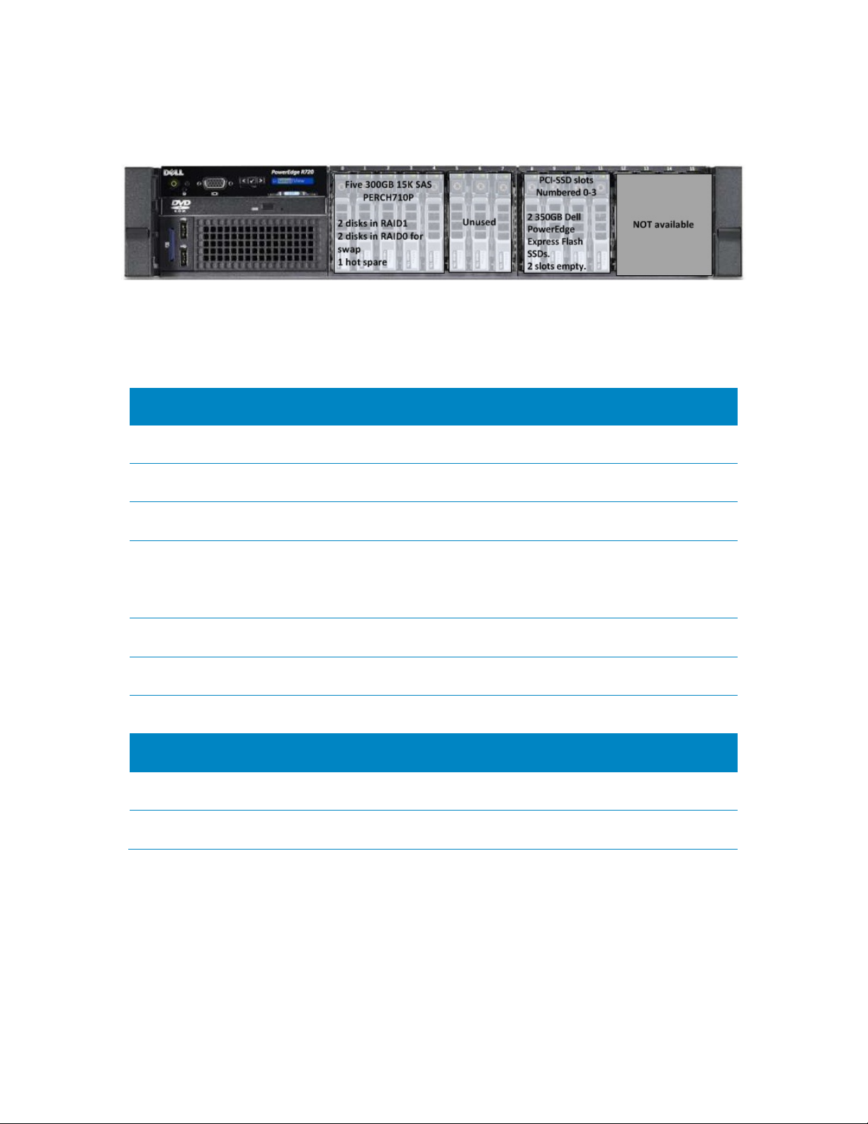
NFS server Figure 2.
NFS server and storage hardware configuration Table 1.
Server configuration
NFS SERVER PowerEdge R720
PROCESSORS Dual Intel(R) Xeon(R) CPU E5-2680 @ 2.70 GHz
MEMORY 128 GB. 16 * 8 GB 1600MT/s RDIMMs
5 * 300 GB 15 K SAS disks
INTERNAL DISKS
INTERNAL RAID CONTROLLER PERC H710P mini (internal)
EXTERNAL RAID CONTROLLER
INTERCONNECT TO CLIENTS Mellanox ConnectX-3 FDR card (slot 5)
Storage Enclosure Four PowerVault MD1200 arrays, daisy chained
Hard Disks 12 * 3 TB 7200 rpm NL SAS drives per storage enclosure
Two drives configured in RAID-0 for the operating system
with one additional drive as a hot spare
Two drives configured in RAID-1 for swap space
PERC H810 adapter (slot 7) connected to the storage
enclosures
Storage configuration
8
Page 9

Improving NFS Performance on HPC Clusters with Dell Fluid Cache for DAS
NFS server software and firmware configuration Table 2.
Software
OPERATING SYSTEM Red Hat Enterprise Linux (RHEL) 6.3z
KERNEL VERSION 2.6.32-279.14.1.el6.x86_64
FILE SYSTEM Red Hat Scalable File System (XFS) 3.1.1-7
SYSTEMS MANAGEMENT Dell OpenManage Server Administrator 7.1.2
Firmware and Drivers
BIOS 1.3.6
iDRAC 1.23.23 (Build 1)
PERC H710/PERC H810
FIRMWARE
PERC DRIVER megasas 00.00.06.14-rh1
INFINIBAND FIRMWARE 2.11.500
INFINIBAND DRIVER Mellanox OFED 1.5.3-3.1.0
The baseline described in this section is very similar to the Dell NSS. One key difference is the use of a
single RAID controller to connect to all four storage arrays. In a pure-NSS environment, two PERC RAID
controllers are recommended for optimal performance. With two PERC cards, the two RAID virtual disks
are combined using Linux Logical Volume Manager (LVM). DFC does not support caching of an LVM
device, hence a single PERC was used for this study.
The NFS server and the attached storage arrays are configured and tuned for optimal performance
based on several past studies
Detailed instructions on configuring this storage solution are provided in Appendix A: Step-by-step
configuration of Dell Fluid Cache for NFS.
4
. A summary of the design choices is provided in Section 2.4.
21.1.0-0007
2.2. Dell Fluid Cache for DAS based solution
The DFC-based NFS solution builds on top of the baseline configuration described in Section 2.1. It
simply adds PCIe SSDs and the DFC software to the baseline configuration. Details of the configuration
are provided in Table 3 and Table 4.
9
Page 10

Improving NFS Performance on HPC Clusters with Dell Fluid Cache for DAS
Hardware configuration for DFC Table 3.
Server configuration
NFS SERVER PowerEdge R720
CACHE POOL Two 350GB Dell PowerEdge Express Flash PCIe SSD
SSD CONTROLLER Internal (slot 4)
Rest of the configuration is the same as baseline, as described in Table 1
Storage configuration
Same as baseline, as described in Table 1
Software and firmware configuration for DFC Table 4.
Software
CACHING SOFTWARE Dell Fluid Cache for DAS v1.0
Rest of the configuration is the same as baseline, as described in Table 2
Firmware and Drivers
PCIe SSD DRIVER
Rest of the configuration is the same as baseline, as described in Table 2
In DFC vocabulary, the cache or cache pool is the SSDs, and the disk that is enabled for caching is the
virtual disk on the PowerVault MD1200s. Most importantly, the methods used to access the data remain
the same as in the baseline case. The I/O clients simply mount the same NFS exported directory as in
the baseline configuration. Detailed instructions on configuring DFC for this storage solution are
provided in Appendix A: Step-by-step configuration of Dell Fluid Cache for NFS.
mtip32xx 1.3.7-1 latest available at the time of this study.
Recommend using mtip32xx v2.1.0
2.3. I/O clients test bed
The pure NFS baseline solution and the NFS+DFC solution were exerci sed us i ng a 64 -node HPC cluster.
This compute cluster was used to provide I/O load to the storage solution and help benchmark the
capabilities of the solution.
Using the latest quarter height Dell PowerEdge M420 blade server
cluster, the 64-client cluster was configured in 20U of rack space. Details of the 64-client test bed are
provided in Table 5. Figure 3 shows the entire test bed including the clients. Note that all I/O traffic to
the NFS server used the InfiniBand network and the IPoIB protocol.
5
as the building block for the I/O
10
Page 11

Improving NFS Performance on HPC Clusters with Dell Fluid Cache for DAS
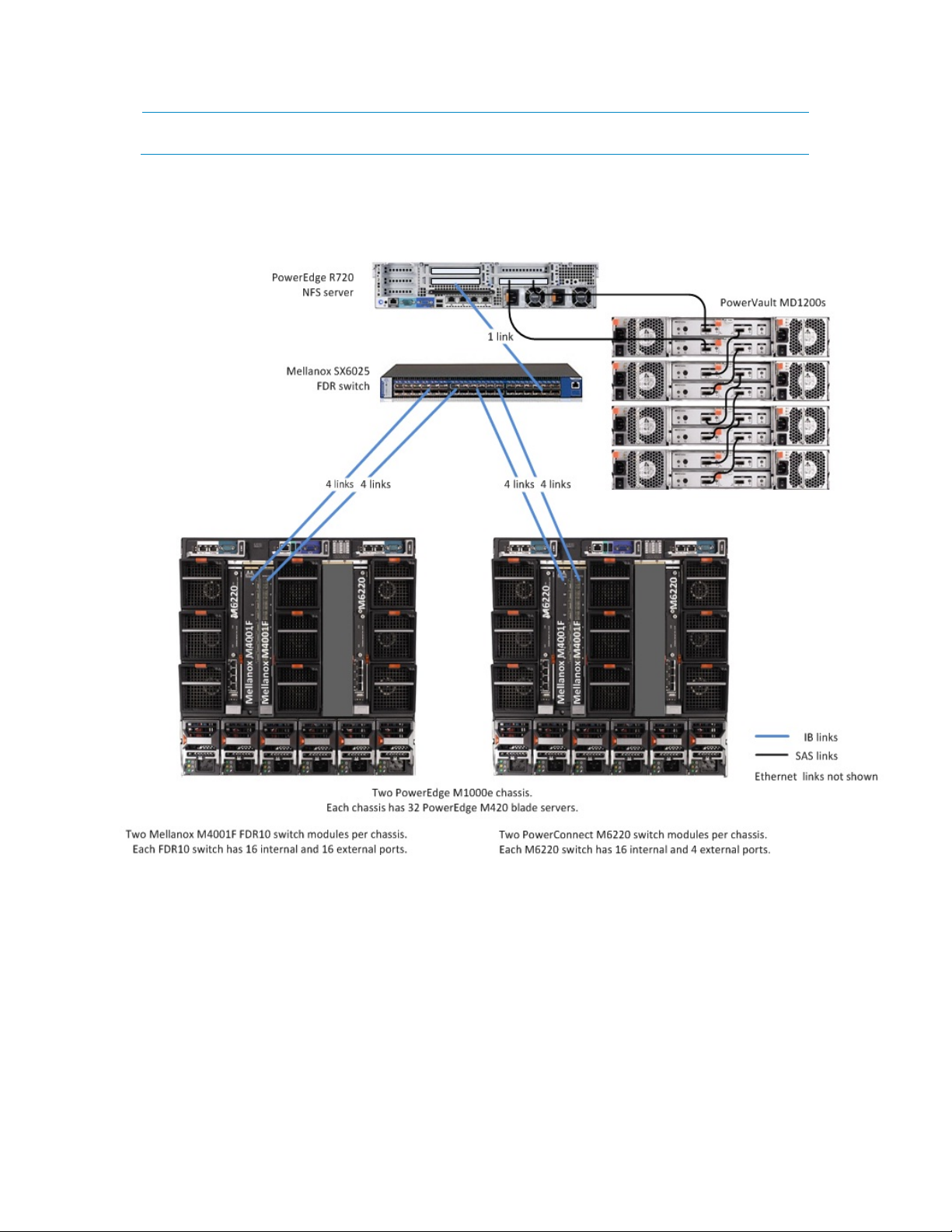
I/O cluster details Table 5.
I/O cluster configuration
CLIENTS
CHASSIS CONFIGURATION
INFINIBAND FABRIC
For I/O traffic
ETHERNET FABRIC
For cluster deployment and
management
CLIENT PowerEdge M420 blade server
PROCESSORS Dual Intel(R) Xeon(R) CPU E5-2470 @ 2.30 GHz
64 PowerEdge M420 blade servers
32 blades in each of two PowerEdge M1000e chassis
Two PowerEdge M1000e chassis, each with 32 blades
Two Mellanox M4001F FDR10 I/O modules per chassis
Two PowerConnect M6220 I/O switch modules per chassis
Each PowerEdge M1000e chassis has two Mellanox M4001
FDR10 I/O module switches.
Each FDR10 I/O module has four uplinks to a rack Mellanox
SX6025 FDR switch for a total of 16 uplinks.
The FDR rack switch has a single FDR link to the NFS server.
Each PowerEdge M1000e chassis has two PowerConnect
M6220 Ethernet switch modules.
Each M6220 switch module has one link to a rack
PowerConnect 5224 switch.
There is one link from the rack PowerConnect switch to an
Ethernet interface on the cluster master node.
I/O compute node configuration
MEMORY 48 GB. 6 * 8 GB 1600 MT/s RDIMMs
INTERNAL DISK 1 50GB SATA SSD
INTERNAL RAID CONTROLLER PERC H310 Embedded
CLUSTER ADMINISTRATION
INTERCONNECT
I/O INTERCONNECT
BIOS 1.3.5
iDRAC 1.23.23 (Build 1)
OPERATING SYSTEM Red Hat Enterprise Linux (RHEL) 6.2
KERNEL 2.6.32-220.el6.x86_64
Broadcom NetXtreme II BCM57810
Mellanox ConnectX-3 FDR10 mezzanine card
I/O cluster software and firmware
11
Page 12
Improving NFS Performance on HPC Clusters with Dell Fluid Cache for DAS
OFED Mellanox OFED 1.5.3-3.0.0
Test bed Figure 3.
2.4. Solution tuning
The NFS server and the attached storage arrays are configured and tuned for optimal performance.
These options were selected based on extensive studies done by the Dell HPC team. Results of these
studies and the tradeoffs of the tuning options are available in [4].
Additionally the DFC configuration was tuned based on experience gained from this study.
This section provides a quick summary of some of the optimizations applied to the storage solution.
Detailed instructions on configuring this storage solution are provided in Appendix A: Step-by-step
configuration of Dell Fluid Cache for NFS.
12
Page 13

Improving NFS Performance on HPC Clusters with Dell Fluid Cache for DAS
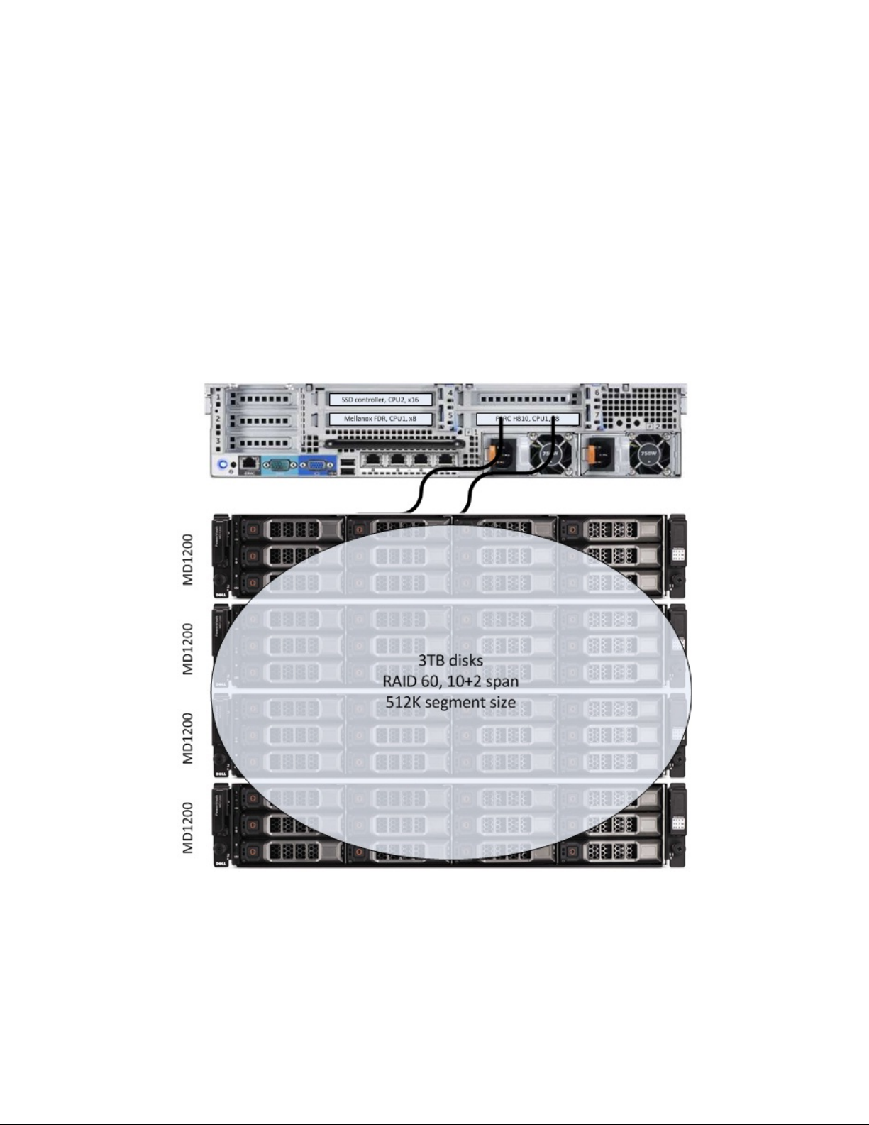
2.4.1. Storage
• 3TB NL SAS disks are selected for large capacity at a cost-effective price point.
• Virtual disks are created using a RAID 60 layout. The RAID 6 span is across 10 data disks and 2
parity disks and the stripe is across all four storage enclosures. This RAID configuration provides
a good balance between capacity, reliability to tolerate multiple disk failures and
performance.
4
• The segment size used for the RAID stripe is 512 KB to maximize performance.4 This value
should be set based on the expected application I/O profile for the cluster.
2.4.2. NFS server
• The default OS scheduler is changed from cfq to deadline to maximize I/O performance.4
• The number of concurrent nfsd threads is increased to 256 from the default of 8 to maximize
performance.
4
• RHEL 6.3 errata Kernel version 2.6.32-279.14.1 fixes some important XFS bugs6 and is
recommended for this solution.
• The PowerEdge R720 is a dual-socket system that uses the Intel Xeon E5-2600 series processors.
On these processors, the PCI-E controller is integrated on the processor chip, making some slots
‘closer’ to one socket and further from the other. This makes card-to-PCI slot mapping an
important factor to consider in performance tuning. The solution presented in this white paper
balances the three PCI cards across the two processors based on server design and engineering
best practices. Refer to Table 1 and Table 3 for card-to-slot recommendations.
• Two internal disks on the NFS server are configured in a RAID 0 stripe and used as swap space
for the operating system. This provides a large swap space in case there is a need for the XFS
repair program to run after an ungraceful system shutdown.
• XFS create options are optimized as well. By default, XFS tries to query the underlying storage
device and optimize the settings accordingly. In the case of using LVM, this works fine;
however, when presenting a raw virtual disk to XFS, it is important to specify the stripe unit
(su) and stripe width (sw). The stripe unit is the stripe element size that was used to format
the virtual disk. The stripe width is the number of data drives in the virtual disk.
By default, there are 8 log buffers, and the -l size option tells xfs how large the log buffers can
become. This can improve metadata performance; however, the larger the log, the longer it
may take to recover a file system that was not unmounted cleanly.
In this solution the mkfs.xfs command used was:
mkfs.xfs -d su=512k,sw=40 -l size=128m /dev/sdc
• There are XFS mount options to optimize the file system as well. The options used for this
solution are similar to the Dell NSS and are noatime, allocsize=1g, nobarrier, inode64,
logbsize=262144, attr2. Details of these mount options are provided in [4].
• The “sync” NFS export option is used when exporting the XFS file system at the expense of
lower performance. This is an added layer of protection to ensure data reliability as the NFS
server will not acknowledge the write until it has written the data to disk.
13
Page 14

Improving NFS Performance on HPC Clusters with Dell Fluid Cache for DAS
• NFSv3 is recommended over NFSv4 based on the performance results of a previous study.
was found that metadata create operations have significantly lower performance when using
NFSv4. For environments where the security enhancements in NFSv4 are more important than
performance considerations, NFSv4 can be used instead.
2.4.3. Dell Fluid Cache for DAS
• In tests conducted at the Dell HPC Engineering laboratory, it was found that enabling the
“Logical Processor” option in the NFS server BIOS improves the random read results of the DFC
configuration by up to 48% when compared to “Logical Processor” Disabled. Dell recommends
enabling the Logical Processor setting when using DFC.
All results in this document have been achieved with this setting enabled.
• DFC can support one to four SSDs in the solution. The DFC cache pool configuration used in this
solution uses two PCIe SSDS. Two SSDs provide ~650GB for caching of reads. Two SSDS are the
minimum required to configure DFC in write-back mode, where writes are cached and
replicated, thus helping to accelerate writes as well as re-reads.
• Caching capacity can be further increased by using four SSDSs in the solution. This will enable
the NFS server to sustain top-line performance for larger amounts of data and/or to support a
larger number of simultaneous clients. Some I/O patterns presented in Section 3 such as large
sequential writes will see improved performance with a larger cache pool.
3
4
It
2.5. Tracking solution health and performa nc e
From a system administrator’s point of view, there are several components in this storage solution that
need to be monitored. This section lists a few simple Dell utilities that can be used to track the
solution’s health and performance statistics.
2.5.1. Server health and monitoring
Dell OpenManage Server Administrator (OMSA) 7 is a Dell utility used to administer and monitor Dell
PowerEdge servers. For the purpose of this solution, OMSA can be used to configure the system BIOS,
create virtual disks both on internal and external drives and monitor the health of the system.
OMSA provides a command-line interface as well as graphical user interface that can be used for all
systems management tasks.
Dell recommends that OMSA’s server and storage management components be installed on the NFS
server in this solution. OMSA v7.1.2 provides support for DFC.
2.5.2. Dell PowerEdge Express Flash PCIe SSD health and monitoring
Configuring the PCIe SSDs in the NFS server is a very straightforward task. The drivers are controlled by
the internal SSD controller. Dell recommends installing the latest Dell drivers to interface with the
SSDs. The version used in this solution is provided in Table 4.
The Express Flash PCIe SSDs are an enterprise class SSD. The performance of the SSD is guaranteed for
the lifetime of the device within the warranty period. There is no expectation of any performance
degradation as the device ages, and blocks are written to the device within the warranty lifetime of
the device.
14
Page 15

Improving NFS Performance on HPC Clusters with Dell Fluid Cache for DAS
[root@nfs-dfc~]# omreport storage controller controller=3
The warranty of the device is expressed in number of years and number of Petabytes written (PBW).
For the recommended 350GB SSD drive, the standard warranty is 3 years, 25 PBW.
The health of the device can be monitored using Dell OMSA utilities. OMSA reports the SSD “Device Life
Remaining” and “Failure Predicted”. “Device Life Remaining” is an indication of the amount of data
written to the device, and is calibrated for the PBW portion of the warranty. It is tracked internally by
the SSD. “Failure Predicte d” tracks the health of the internal components of the SSD. If failure is
predicted, it is recommended that the SSD be replaced. This field does not imply performance
degradation but suggests that the SSD is starting to have component failure counts that are higher than
the preset thresholds.
Example output is shown in Figure 4. For more details refer to [8].
PCIe SSD health Figure 4.
Controller PCIe-SSD SubSystem (Not Available)
Controllers
ID : 3
Status : Ok
Name : PCIe-SSD SubSystem
<…snip…>
PCIe-SSD Extender
ID : 0
Status : Ok
Name : PCIe-SSD Extender
State : Ready
Connector Type : Non-RAID
Termination : Not Applicable
SCSI Rate : Not Applicable
Physical Disks
ID : 0:2:0
Status : Ok
Name : Physical Device 0:2:0
State : Ready
Power Status : Not Applicable
Bus Protocol : PCIe
Media : SSD
Device Life Remaining : 100%
Failure Predicted : No
Revision : B1490208
Driver Version : 1.3.7
Model Number : DELL_P320h-MTFDGAL350SAH
<…snip…>
15
Page 16

Improving NFS Performance on HPC Clusters with Dell Fluid Cache for DAS
2.5.3. Dell Fluid Cache for DAS health and monitoring
DFC provides a very simple command-line utility /opt/dell/fluidcache/bin/fldc that can be
used for configurati o n an d ma na gem e nt. A lt er na te ly , the DFC configuration can be accomplished using
the OMSA GUI. DFC is a component under the storage sub-section of the OMSA GUI.
/opt/dell/fluidcache/bin/fldcstat is a command-line utility that provides extensive statistics
of the cache hits on the system, disk IO, etc.
Additional details are available in the DFC User’s Guide in [3].
3. Performance
This section presents the results of performance tests conducted on the storage solution described in
Section 2. Performance tests were run to evaluate the following common I/O patterns.
• Large sequential reads and writes
• Small random reads and writes
• Metadata operations
These tests were performed over the IP-over-InfiniBand (IPoI B ) network as described in Section 2.3.
The iozone and mdtest benchmarks were used for this study. Details of the benchmarks and test
process are provided in Appendix B: Benchmarks and tests.
Iozone was used for the sequential tests as well as the random tests. The I/O access patterns are N-toN, i.e., each thread reads and writes to its own file. Iozone was executed in clustered mode and one
thread was launched on each compute node. For the sequential tests, the performance metric used
was throughput in terms of MiB/s. For random tests, I/O operations per second (IOPS) was the metric.
The large sequential read and large sequential write tests were conducted using a request size of 1024
KB. The total amount of data written was 256 GB. (Recall from Table 1 that the NFS server RAM is 128
GB.) This is to ensure that the total I/O exceeds the NFS server memory since the goal is to test the
disk and storage solution performance.
The small random tests were performed with 4 KB record sizes since the size corresponds to typical
random I/O workloads. Each client rea ds and writes a smaller 4 GB file for these tests.
The metadata tests were performed with the mdtest utility and include file creates, stats, and
removals.
While these benchmarks do not cover every I/O pattern, they help characterize the I/O performance of
this storage solution.
Each set of tests was run on a range of clients to test the scalability of the solution. The number of
simultaneous clients involved in each test was varied from one to 64 clients. The client test bed is
described in Section 2.3.
Tests were performed on three configurations:
• Baseline - This is the pure NFS storage solution as described in Section 2.1.
16
Page 17

Improving NFS Performance on HPC Clusters with Dell Fluid Cache for DAS
• DFC in Write-Back mode (DFC-WB) – This configuration builds on the baseline by adding DFC as
described in Section 2.2, and DFC is configured to operate in Write-Back (WB) mode. WB mode
allows the caching of writes on the cache pool. WB mode requires the data to be written to a
minimum of two PCIe SSDs. Both re-reads and writes are accelerated.
• DFC in Write-Through mode (DFC-WT) – This configuration builds on the baseline, but he re DFC
is configured in Write-Through (WT) mode. WT mode forces writes to both the cache and
virtual back end disk simultaneously.
The following sections present the results of the different I/O patterns.
3.1. Sequential writes and reads
The results of the IPoIB sequential write tests are shown in Figure 5. The figure shows the aggregate
throughput that can be achieved when a number of clients are simultaneously writing to the storage
over the InfiniBand fabric.
The results show that baseline configuration can reach a peak write throughout of ~2,000 MiB/s. Recall
that this is with the “sync” NFS export option, and this peak throughput demonstrates how well the
configuration is tuned
was ~400 MiB/s with a peak of ~600 MiB/s. The lower sequential write performance with DFC is due to
two factors: the pure sequential write performance of the SSDs is lower than the storage array and the
write-back cache has to replicate dirty blocks which means every write to the cache has to be written
to two SSDs. Subsequent re-write operations were found to have ~25% higher throughput as the files
are already in the DFC cache.
4
. With DFC in WB mode, labeled DFC-WB in Figure 5, the throughput measured
Switching to WT mode and eliminating the replica blocks doubles the sequential write performance.
Peak performance approaches ~1,000 MiB/s as seen in Figure 5, labeled DFC-WT. Recall that all writes
go directly to the backend disk in addition to being cached on the SSDs in WT mode.
If the I/O pattern is such that there is a large amount of sequential data written to the backend
storage initially followed by subsequent reads, re-reads, and small writes, one method to take
advantage of DFC performance on random workload (Section 3.2) while minimizing the sequential write
performance penalty is to disable caching on the backend disk during the write operation. Although this
might not be an option for production clusters, smaller single-user/single-application environments
might be able to adopt this approach. DFC provides very simple utilities to accomplish this. Once the
data is written to the backend store, for example by a gene sequencer, caching on the backend disk
can be re-enabled. Subsequent reads, re-reads, and writes can be nefi t grea t ly f rom DFC technology.
17
Page 18

Improving NFS Performance on HPC Clusters with Dell Fluid Cache for DAS
Large sequential wr ite performance Figure 5.
Sequential writes
2500
2000
1500
1000
500
Throughput in MiB/s
0
1 2 4 8 16 32 48 64
Number of concurrent clients
baseline DFC-WB DFC-WT
Large sequential r e ad perfor mance Figure 6.
Sequential reads
3500
3000
2500
2000
1500
1000
Throughput in MiB/s
500
0
1 2 4 8 16 32 48 64
Number of concurrent clients
baseline DFC-WB DFC-WT
Figure 6 shows the results of the sequential read tests. The aggregate throughput achieved when a
number of clients are simultaneously reading files is plotted on the graph. The figures show the peak
read throughput for the baseline is ~2,500 MiB/s. With the DFC configuration, reads are 13% to 60%
18
Page 19

Improving NFS Performance on HPC Clusters with Dell Fluid Cache for DAS
better than the baseline since the data is already in the DFC cache. As expected on read operations,
WB and WT tests have similar performance and can reach peak throughout of ~3050 MiB/s.
3.2. Random writes and reads
Figure 7 plots the aggregate IOPs when a number of clients are simultaneously issuing random writes to
their files. The baseline configuration can sustain ~1,600 IOPs on writes. Random writes are limited by
capability of the RAID controller and the disks seek latency of the backend dis ks .
With DFC in WB mode, the true value of DFC becomes apparent. Write IOPs are up to 6.4 times higher
(6.4x) than the baseline configuration at 64 clients. In random write tests, the cache warms up very
quickly since random operations tend to be ‘small’ with a 4k block size. In WT mode, DFC behavior and
performance is similar to the baseline as all writes go through to the backend disk.
Figure 8 plots the aggregate read IOPs when a number of clients are simultaneously issuing random
read operations. The baseline configuration sustains ~9,300 IOPS. As expected on read operations, DFC
WB and WT tests have similar performance and peak at 123 ,000 IOPs at 32 clients! That is over 20x
higher than the baseline performance.
Clearly read requests are being fulfilled from the DFC cache and that is the value of such caching
software. The question that arises is about worst case read performance. What is the drop in
performance when the data is accessed after it has been evicted from the cache? This scenario is
explored in Section 3.4.
Random write pe rformance Figure 7.
Random writes
14000
12000
10000
8000
IOPS
6000
4000
2000
0
1 2 4 8 16 32 48 64
Number of concurrent clients
baseline DFC-WB DFC-WT
19
Page 20

Improving NFS Performance on HPC Clusters with Dell Fluid Cache for DAS
Random re ad p erformance Figure 8.
Random reads
140000
120000
100000
80000
IOPS
60000
40000
20000
0
1 2 4 8 16 32 48 64
Number of concurrent clients
baseline DFC-WB DFC-WT
3.3. Metadata tests
This section presents the results of metadata tests using the mdtest benchmark. In separate tests, one
million files were created, stated and unlinked concurrently from multiple NFS clients on the NFS
server. These results are presented in Figure 9, Figure 10, and Figure 11, respectively, as the number
of metadata operations per second. Each client ran a single instance of the mdtest benchmark for test
cases from 1 to 64 clients. For 128, 256 and 512 concurrent client tests, each client ran 2, 4, and 8
threads of the benchmark.
From the figures it can be seen that DFC-WT and DFC-WB create and remove tests have similar
performance. This indicates that the metadata tests are not bandwidth sensitive. If they were, the WT
tests would be expected to outperform the WB tests. This result needs further analysis. It is likely that
these operations are more latency sensitive.
20
Page 21

Improving NFS Performance on HPC Clusters with Dell Fluid Cache for DAS
Metadata file create performance Figure 9.
File create
45000
40000
35000
30000
25000
20000
15000
10000
5000
0
Number of create() ops per second
1 2 4 8 16 32 48 64 128 256 512
Number of concurrent clients
baseline DFC-WB DFC-WT
File create and file remove tests show similar results with the baseline out-performing the DFC
configuration. File stat is a read operation and here the DFC configuration outperforms the baseline by
up to 80%.
Metadata file stat performance Figure 10.
File stat
200000
180000
160000
140000
120000
100000
80000
60000
40000
20000
Number of stat() ops per second
0
1 2 4 8 16 32 48 64 128 256 512
Number of concurrent clients
baseline DFC-WB DFC-WT
21
Page 22

Improving NFS Performance on HPC Clusters with Dell Fluid Cache for DAS
Metadata file remove performa nce Figure 11.
File remove
50000
45000
40000
35000
30000
25000
20000
15000
10000
5000
Number of remove() ops per second
0
1 2 4 8 16 32 48 64 128 256 512
Number of concurrent clients
baseline DFC-WB DFC-WT
3.4. Cold-cache tests
For all the test cases discussed in the previous sections, the file system was unmounted and remounted from the I/O clients and the NFS server between test iterations. This was done to eliminate
the impact of caching in the client and server RAM memory, and to present true disk performance.
However, with DFC there is another layer of caching – the DFC cache pool or the SSDs. DFC treats the
SSDs plus the backend virtual disk as part of the DFC configuration. Thus, unmounting the file system
does not necessarily evict the data in the DFC cache. On a subsequent re-mount of the file system, the
last used data is likely to be accessed from the SSD.
A cold-cache is when the data being accessed is not in the SSD cache and has to be retrieved from
backend storage. In all our test cases, all writes are cold-writes since they are fresh writes and not a
re-write of existing data. However all reads are likely to be cache hits since the SSD cache is larger
than the total I/O size. In a production cluster, a worst-case read scenario could arise when a read
request is issued for data that was already flushed out of the SSD cache (say, to make room for newer
requests). The results presented in this section simulate such a cold-cache read.
To simulate a cold-cache, caching was disabled on the backend disk after every write test. This
ensured that the data in the SSD cache was flushed out the backend disk. Additionally the SSDs were
removed from the DFC configuration. Then the SSDs were re-added, and caching re-enabled on the
backend disk and the read test cases executed. Results are presented in Figure 12 and Figure 13. Tests
were conducted with WB mode only. As seen in previous sections, WB and WT mode do not impact read
tests. A cold-cache also does not impact write tests. Consequently, the graphs below present only coldcache read results.
22
Page 23

Improving NFS Performance on HPC Clusters with Dell Fluid Cache for DAS
Figure 12 shows that on a cold-cache read for sequential tests, the throughput of the DFC configuration
drops from a peak of ~3,050 MiB/s to ~1,050 Mi/s. Data needs to be pulled from backend storage and
hence the drop in performance. This is lower than the baseline throughput.
Cold-cache sequential reads Figure 12.
Cold-cache Sequential Reads
3500
3000
2500
2000
1500
1000
Throughput in MiB/s
500
0
140000
120000
100000
80000
IOPS
60000
40000
20000
1 2 4 8 16 32 48 64
Number of concurrent clients
DFC-WB DFC-WB-coldcache baseline
Cold-cache random reads Figure 13.
Cold-cache Random Reads
0
1 2 4 8 16 32 48 64
Number of concurrent clients
FC-WB FC-WB-coldcache baseline
23
Page 24

Improving NFS Performance on HPC Clusters with Dell Fluid Cache for DAS
Figure 13 shows that on a cold-cache read for the random tests, peak IOPS of the DFC configurations
drop from ~123,000 IOPs to ~80,000 IOPs. Interestingly this is higher than the baseline IOPs of ~9,300,
and explained below.
Figure 14 helps explain why the cold-cache read behavior is different for sequential and random I/O. It
uses the output of fldcstat, a utility provided by DFC that displays statistics for the DFC
configuration.
CacheIO-DiskIO on cold-cache reads Figure 14.
fldcstat - CacheIO-DiskIO
8000
6000
4000
2000
0
-2000
-4000
CacheIO-DiskIO MiB
-6000
-8000
(-ve is from disk, +ve from cache)
-10000
Random Reads-coldcache Sequential Reads-coldcache
One piece of information provided by fldcstat is CacheIO-DiskIO. This shows the number of bytes
read and written to the cache device minus the number of bytes read and written to the disk. A
positive value shows IO activity is being served mostly by the cache while, a negative value indicates
more disk IO is being performed than cache IO.
Figure 14 plots CacheIO-DiskIO over the duration of the cold-cache sequential read and random read
tests for the 64 concurrent client test case. From the figure it is seen that during sequential reads
there is a lot of disk IO followed by cache IO. This pattern repeats for the duration of the test. Data is
pulled from the backend disk to the SSDs, served from the SSD, and this cycle is repeated. However for
the random read tests, there is backend disk IO at the start, but the cache quickly warms up and
subsequent read requests are satisfied directly from the cache. This helps explain why cold-cache
sequential reads have lo w throughput—lower than the DFC-WB configuration, and also lower than the
baseline. Cold-cache random reads do take a hit in IOPS compared to the DFC-WB configuration but,
due to the nature of the small I/O block size (4k) and the longer duration of the test itself, show
significantly better performance than the baseline since the DFC cache warms up very quickly.
24
Page 25

Improving NFS Performance on HPC Clusters with Dell Fluid Cache for DAS
4. Conclusion
This Dell technical white paper describes a method to improve NFS performance using Dell Fluid
Cache for DAS in an HPC e nvi ro nme nt. It presents measured cluster-level results of several different
I/O patterns to quantify the performance of a tuned NFS solution and measure the performance boost
provided by DFC.
The test results in this paper indicate that DFC is a great fit for environments where:
• There is heavy read I/O workload, either sequential or random reads.
• Heavy random write I/O workload with a large number of clients writing to the storage.
• Lots of clients are performing I/O at the same time.
• Mixed I/O workload where it is critical to sustain a balance between throughput and IOPs and
an SSD based solution is the best fit.
5. References
1. Dell High-performance Computing NFS Storage Solutions (NSS)
http://www.dell.com/us/enterprise/p/d/hpcc/storage-dell-nss
2. Solid State Drive vs. Hard Disk Drive Price and Performance Study
http://www.dell.com/downloads/global/products/pvaul/en/ssd_vs_hdd_price_and_performance_s
tudy.pdf
3. Dell Fluid Cache for DAS
Dell Fluid Cache for DAS User’s Guide at www.dell.com/support
http://www.dell.com/us/enterprise/p/poweredge-r720/pd
4. NFS tuning and the optimized Dell NFS Storage Solutions (NSS)
Dell™ HPC NFS Storage Solution
Dell HPC NFS Storage Solution High Availability (NSS-HA) Configurations with Dell PowerEdge 12th
Generation Servers
http://i.dell.com/sites/content/business/solutions/engineering-docs/en/Documents/hpc-nfs-
storage-solution.pdf
Optimizing DELL™ PowerVault™ MD1200 Storage Arrays for High Performance Computing (HPC)
Deployments
5. Dell PowerEdge M420 blade
http://www.dell.com/us/enterprise/p/poweredge-m420/pd?~ck=anav
6. XFS bugzilla reference
https://bugzilla.redhat.com/show_bug.cgi?id=813137
7. Dell OpenManage Server Administrator
25
Page 26

Improving NFS Performance on HPC Clusters with Dell Fluid Cache for DAS
http://en.community.dell.com/techcenter/systems-management/w/wiki/1760.openmanageserver-administrator-omsa.aspx
8. Dell PowerEdge Express Flash PCIe SSD
www.dell.com/poweredge/expressflash
http://support.dell.com/support/edocs/storage/Storlink/PCIe%20SSD/UG/en/index.htm
http://content.dell.com/us/en/home/d/solutions/limited-hardware-warranties.aspx
26
Page 27

Improving NFS Performance on HPC Clusters with Dell Fluid Cache for DAS
Appendix A: Step-by-step configuration of Dell Fluid Cache for NFS
This appendix provides detailed step-by-step instructions on the configuration of the storage solution
described in this white paper. Readers familiar with Dell’s NSS line of solutions
configuration steps to be very similar to the NSS recipe.
Contents
A.1. Hardware checklist and cabling .......................................................................... 27
A.2. NFS server set up ............................................................................................ 28
A.3. NFS server configuration and tuning ..................................................................... 29
A.4. Virtual disk configuration .................................................................................. 31
A.5. XFS and DFC configuration................................................................................. 33
A.6. Useful commands and references ........................................................................ 34
A.7. Performance tuning on clients ............................................................................ 34
will find the
A.1. Hardware checklist and cabling
The storage solution described in this white paper comprises of an NFS server, direct-attached external
storage, and the Dell Fluid Cache for DAS (DFC) software.
A PowerEdge R720 is used as the NFS server. This solution uses four PowerVault MD1200s as the
attached storage to provide 144TB of raw capacity.
Refer to Table 1, Table 2, Table 3 and Table 4 for the complete hardware and firmware configuration
of the server and the storage. This includes the PCI slot-to-card mapping for the server.
Figure 15 shows the cabling of the PowerVault MD1200s to the PERC H810 adapter on the server.
27
Page 28

Improving NFS Performance on HPC Clusters with Dell Fluid Cache for DAS
Solution cabling Figure 15.
A.2. NFS server set up
After the PowerEdge R720 server is ready and cabled to the PowerVault MD1200, check Table 2 and
Table 4 for details on the software used for the solution.
1. Create two virtual disks on the five internal disks of the PowerEdge R720. This can be done through
the Ctrl+R menu on server boot-up.
• One RAID 1 virtual disk on two drives. This will be used for the operating system. Configure
one additional drive as the hot spare for this RAID group.
One RAID 0 virtual disk on two drives. This will be used for swap space.
2. Install Red Hat Enterprise Linux (RHEL 6.3) on the RAID 1 virtual disk of the PowerEdge R720.
To use any GUI features of DFC or Dell OpenManage, select the “Desktop” group of
packages.
3. This solution is based on the 2.6.32-279.14.1.el6.x86_64
errata kernel version including kernel-devel and kernel-firmware rpms. Add these kernel
rpms to the system using the “rpm -ivh” flags. Do not upgrade the kernel version (“Uvh”).
errata kernel for RHEL 6.3. Install this
4. Reboot the server into the .14.1 kernel. Double check the kernel version.
[root@nfs-dfc ~]# uname -a
Linux nfs-dfc 2.6.32-279.14.1.el6.x86_64 #1 SMP Mon Oct 15 13:44:51 EDT
2012 x86_64 x86_64 x86_64 GNU/Linux
28
Page 29

Improving NFS Performance on HPC Clusters with Dell Fluid Cache for DAS
5. Install the Red Hat Scalable File System (XFS) packages that are part of RHEL 6.3 add-on.
xfsprogs-3.1.1-7.el6.x86_64 and xfsdump-3.0.4-2.el6.x86_64
6. Install at a minimum the “Server Instrumentation”, “Server Administrator Web Server” and
“Storage Management” components of Dell OpenManage Server Administrator
PowerEdge R720. Note that only v7.1.2 supports DFC at the time of writing. A newer OpenManage
version cannot be used instead.
• Resolve any rpm dependencies as prompted by the OMSA setup scripts. For example, yum
install libwsman1 openwsman-client.
7. Install Dell Fluid Cache for DAS v1.0. A DFC license will be needed to use the product. Copy the
license file to the server. Execute the DFC setup script and resolve any Linux dependencies as
required.
8. Check that DFC is installed and the service is running.
[root@nfs-dfc ~]# service fluid_cache status
fldc_cfm (5794) is running...
fldc_agent (5887) is running...
fldc is running...
[root@nss-rna ~]#
(OMSA) v7.1.2 on the
9. Install the appropriate Dell drivers for the PowerEdge R720. At a minimum, the PCIe SSD driver
must be updated. v2.1.0 is the recommended version.
10. Install Mellanox OFED 1.5.3-3.1.0 for RHEL 6.3 on the server.
• First build Mellanox OFED for errata kernel 2.6.32-279.14.1 using the iso downloaded from
Mellanox’s website. This step will generate a new iso in /tmp.
<MLNX_OFED_iso_mount_point>/mlnx_add_kernel_support.sh -i
MLNX_OFED_LINUX-1.5.3-3.1.0-rhel6.3-x86_64.iso
• Install Mellanox OFED from the new iso generated in /tmp.
<new_iso_mount_point>/mlnxofedinstall
• Resolve any rpm dependencies for OFED. For example, yum install tcl tk.
Reboot the server for these changes to take effect.
A.3. NFS server configuration and tuning
Tune the PowerEdge R720 server as described below.
1. Change the number of nfsd threads to 256. Make a backup of /etc/sysconfig/nfs and change the
number of threads. Set the NFS service to start on boot.
# cp /etc/sysconfig/nfs{,.orig}
# sed -i 's/#RPCNFSDCOUNT=8/RPCNFSDCOUNT=256/' /etc/sysconfig/nfs
# chkconfig nfs on
29
Page 30

Improving NFS Performance on HPC Clusters with Dell Fluid Cache for DAS
2. Change the OS I/O scheduler to “deadline”. To the end of the kernel line in /etc/grub.conf for
the .14.1 errata kernel, add elevator=deadline.
3. To work around a known error message with the PCIe SSDs, add the following kernel parameter: to
the end of the kernel line in /etc/grub.conf for the .14.1 errata kernel, add pci=nocrs.
More details are available at https://bugzilla.kernel.org/show_bug.cgi?id=42606
and https://bugzilla.redhat.com/show_bug.cgi?id=620313.
4. Configure the RAID 0 virtual disk created in Step 1, Section A.2 to be a swap device.
First note the controller ID for the PERC H710P Mini (ID 0) and the device name for the RAID 0
virtual disk (/dev/sdb) from output of the command below.
[root@nfs-dfc ~]# omreport storage controller
List of Controllers in the system
Controllers
ID : 0
Status : Ok
Name : PERC H710P Mini
Slot ID : Embedded
State : Ready
Firmware Version : 21.1.0-0007
Minimum Required Firmware Version : Not Applicable
Driver Version : 00.00.06.14-rh1
<…snip…>
[root@nfs-dfc ~]# omreport storage vdisk controller=0
List of Virtual Disks on Controller PERC H710P Mini (Embedded)
Controller PERC H710P Mini (Embedded)
ID : 0
Status : Ok
Name : Virtual Disk 0
State : Ready
Partitions : Not Available
Hot Spare Policy violated : Not Assigned
Encrypted : No
Layout : RAID-1
Size : 278.88 GB (299439751168 bytes)
Associated Fluid Cache State : Not Applicable
Device Name : /dev/sda
<…snip…>
ID : 1
Status : Ok
Name : Virtual Disk 1
State : Ready
30
Page 31

Improving NFS Performance on HPC Clusters with Dell Fluid Cache for DAS
Partitions : Available
Hot Spare Policy violated : Not Applicable
Encrypted : No
Layout : RAID-0
Size : 557.75 GB (598879502336 bytes)
Associated Fluid Cache State : Not enabled
Device Name : /dev/sdb
Bus Protocol : SAS
Media : HDD
Read Policy : Adaptive Read Ahead
Write Policy : Write Back
Cache Policy : Not Applicable
Stripe Element Size : 64 KB
Disk Cache Policy : Disabled
Now create a swap space on the RAID 0.
# mkswap –L SWAP /dev/sdb
Turn on swap.
# swapon –p 10 /dev/sdb
Edit /etc/fstab and add an entry for this swap device.
“LABEL=SWAP swap swap pri=10 0 0”
Make sure the entry is listed before the default swap space the OS install created.
Test that swap can be enabled automatically when the server boots.
# swapoff –a
# swapon -s
# swapon –a
# swapon –s
5. Configure an ib0 IP-address on the InfiniBand interface. This is the IP the I/O clients will use to
mount the NFS share. It should be on the same subnet as the I/O clients.
Reboot the server for all these changes to take effect.
A.4. Virtual disk configuration
Create a virtual disk on the PowerVault MD1200s. This disk will be used as the NFS storage. All the
commands in this section are executed on the PowerEdge R720 NFS server.
1. Note the controller ID of the PERC H810 adapter. From the output below, the controller ID is 1.
[root@nfs-dfc]# omreport storage controller
List of Controllers in the system
<…snip…>
ID : 1
31
Page 32

Improving NFS Performance on HPC Clusters with Dell Fluid Cache for DAS
Status : Ok
Name : PERC H810 Adapter
Slot ID : PCI Slot 7
State : Ready
Firmware Version : 21.1.0-0007
Minimum Required Firmware Version : Not Applicable
Driver Version : 00.00.06.14-rh1
Minimum Required Driver Version : Not Applicable
Storport Driver Version : Not Applicable
Minimum Required Storport Driver Version : Not Applicable
<…snip…>
2. Check that the PERC H810 Adapter has 48 3TB disks available.
[root@nfs-dfc]# omreport storage pdisk controller=1
Disks will be numbered 0:0:0 to 0:0:11, 0:1:0 to 0:1:11, 0:2:0 to 0:2:11 and 0:3:0 to 0:3:11 in the
format <connector:enclosureID:portID>
3. Create a RAID 60 virtual disk with spanlength of 12 and stripe size of 512KB on the PowerVault
MD1200s.
[root@nfs-dfc]# omconfig storage controller controller=1
action=createvdisk raid=r60 size=max stripesize=512kb spanlength=12
pdisk=0:0:0,0:0:1,0:0:2,0:0:3,0:0:4,0:0:5,0:0:6,0:0:7,0:0:8,0:0:9,0:0:1
0,0:0:11,0:1:0,0:1:1,0:1:2,0:1:3,0:1:4,0:1:5,0:1:6,0:1:7,0:1:8,0:1:9,0:
1:10,0:1:11,0:2:0,0:2:1,0:2:2,0:2:3,0:2:4,0:2:5,0:2:6,0:2:7,0:2:8,0:2:9
,0:2:10,0:2:11,0:3:0,0:3:1,0:3:2,0:3:3,0:3:4,0:3:5,0:3:6,0:3:7,0:3:8,0:
3:9,0:3:10,0:3:11
4. Check that the virtual disk has finished initializing and is ready. This can take several hours. Double
check the size of the device (110TB) and note the device name (/dev/sdc) from the command
below.
[root@nfs-dfc ~]# omreport storage vdisk controller=1
List of Virtual Disks on Controller PERC H810 Adapter (Slot 7)
Controller PERC H810 Adapter (Slot 7)
ID : 0
Status : Ok
Name : Virtual Disk 0
State : Ready
Hot Spare Policy violated : Not Assigned
Encrypted : No
Layout : RAID-60
Size : 111,760.00 GB (120001386250240 bytes)
Associated Fluid Cache State : Active
Device Name : /dev/sdc
Bus Protocol : SAS
Media : HDD
Read Policy : No Read Ahead
Write Policy : Write Back
Cache Policy : Not Applicable
32
Page 33

Improving NFS Performance on HPC Clusters with Dell Fluid Cache for DAS
Stripe Element Size : 512 KB
Disk Cache Policy : Disabled
A.5. XFS and DFC configuration
In this final step of the configuration on the server, the XFS file system is created, DFC is configured,
and the storage exported to the I/O clients via NFS.
1. Create the XFS file system on the RAID 60 virtual disk attached to the PERC H810 adapter. Note the
stripe unit (su) and stripe width (sw). The stripe unit is the stripe element size that was used to
format the virtual disk in step 3, Section A.4. The stripe width is the number of data drives in the
virtual disk. This solution uses 48 disks, a RAID 6 configuration with a spanlength of 12 (10 data
disks and 2 parity disks) and that results in a total of 40 data disks.
[root@nfs-dfc ~]# mkfs.xfs -d su=512k,sw=40 -l size=128m /dev/sdc
2. Set up the cache pool for Dell Fluid Cache.
Verify that the DFC service is running.
[root@nfs-dfc ~]# service fluid_cache status
Add two SSDs to the cache pool and check the status.
[root@nfs-dfc ~]# fldc --add --ssd=/dev/rssda -v
[root@nfs-dfc ~]# fldc --add --ssd=/dev/rssdb –v
[root@nfs-dfc ~]# fldc -v --list --ssd
Enable caching on the RAID 60 external virtual disk. Note the device and the mode for caching
(write-back in the command below).
[root@nfs-dfc ~]# fldc --enable --disk=/dev/sdc --mode=wb
At this point, DFC will create a new device called /dev/fldc0 that includes the cache pool and
the virtual disk.
Check the DFC status
[root@nfs-dfc ~]# fldc --status
3. Mount the file system. Note the device mounted is /dev/fldc0
[root@nfs-dfc ~]# mount -o
noatime,allocsize=1g,nobarrier,inode64,logbsize=262144,attr2 /dev/fldc0
/home/xfs/
4. Export this file system over NFS by modifying /etc/exports. Note that the share is exported with
the ‘sync’ option.
[root@nfs-dfc ~]# cat /etc/exports
/home/xfs *(rw,no_root_squash,sync)
5. Restart the NFS service. Now the clients can mount the NFS share over the ib0 interface. Note that
this solution recommends NFS v3 based on the results of a previous study
[root@nfs-dfc ~]# service nfs restart
.
33
Page 34

Improving NFS Performance on HPC Clusters with Dell Fluid Cache for DAS
Example on the client:
[root@compute-0-0 ~]# mount –o vers=3 <ib0-IP-of-NFS-server>:/home/xfs
<mount-point-on-client>
A.6. Useful commands and references
DFC is installed in /opt/dell/fluidcache.
1. fldc is the command-line utility to configure DFC. Use fldc –h for the flags available.
2. To check status use fldc –-status.
3. Check for fldc events with fldc –-events. Use fldc –-num=<n> --events to see more than
last 10 events.
4. /opt/dell/fluidcache/bin/fldcstat is the utility to view and monitor DFC statistics. Check
the fldcstat manual pages for options and descriptions of the statistics that are available.
5. Dell OpenManage Server Administrator provides a GUI to configure, administer, and monitor the
server. Browse to https://localhost:1311
6. Enable IP ports on both the cluster servers. The list of ports to be enabled is in the Red Hat Storage
Administration Guide.
on the NFS server to see this GUI.
https://access.redhat.com/knowledge/docs/enUS/Red_Hat_Enterprise_Linux/6/html/Storage_Administration_Guide/s2-nfs-nfs-firewallconfig.html
Alternately, turn off the firewall. Ensure that your public and private interfaces are on a secure
network and be aware of the security implications of turning off the firewall before implementing
this alternative:
[root@nfs-dfc ~]# service iptables stop; chkconfig iptables off
A.7. Performance tuning on clients
1. For each client, add the following to /etc/sysctl.conf to increase the TCP receive memory
buffer size
# increasing the default TCP receive memory size
net.ipv4.tcp_rmem = 4096 2621440 16777216
Activate the changes with sysctl -p.
2. Mount clients using NFS v3. A previous study
create performance than NFS v4. This solution recommends NFS v3 except in cases where the
security enhancements in NFS v4 are critical.
[root@compute-0-0 ~]# mount –o vers=3 <ib0-IP-of-NFS-server>:/home/xfs
<mount-point-on-client>
reported that NFSv3 has dramatically better metadata
34
Page 35

Improving NFS Performance on HPC Clusters with Dell Fluid Cache for DAS
IOzone Argument
Description
-i 0
Write test
-i 1
Read test
-i 2
Random Access test
-+n
No retest
-c
Includes close in the timing calculations
-t
Number of threads
-e
Includes flush in the timing calculations
-r
Records size
-s
File size
Appendix B: Benchmarks and tests
The iozone benchmark was used to measure sequential read and write throughput (MiB/sec) as well as
random read and write I/O operations per second (IOPS).
The mdtest benchmark was used to test metadata operation performance.
B.1. IOzone
You can download the IOzone from http://www.iozone.org/. Version 3.4.08 was used for these tests
and installed the compute nodes.
The IOzone tests were run from 1-64 nodes in clustered mode. All tests were N-to-N, that is N clients
would read or write N independent files.
Between tests, the following procedure was followed to minimize cache effects:
• Unmount NFS share on clients.
• Stop the NFS service and unmount the XFS file system on the server.
• Mount XFS file system on the server and start the NFS service.
• Mount NFS Share on clients.
In addition for the cold cache tests described in Section 3.4, the disk managed by Dell Fluid Cache for
DAS was disabled and the SSDs that are part of the cache pool were disabled after a write operation.
DFC was re-configured prior to the read tests thus ensuring that all reads were from a cold-cache.
The following table describes the IOzone command line arguments.
35
Page 36

Improving NFS Performance on HPC Clusters with Dell Fluid Cache for DAS
IOzone Argument
Description
-t
Number of threads
+m
Location of clients to run IOzone on when in clustered
-w
Does not unlink (delete) temporary file
-I
Use O_DIRECT, bypass client cache
-O
Give results in ops/sec.
mode
For the sequential tests, file size was varied along with the number of clients such that the total
amount of data written was 256G (number of clients * file size per client = 256G).
IOzone Sequential Writes
# /usr/sbin/iozone -i 0 -c –e –w –r 1024k –s 4g –t 64 -+n -+m ./clientlist
IOzone Sequential Reads
# /usr/sbin/iozone -i 1 -c -e -w -r 1024k -s 4g -t 64 -+n -+m ./clie ntlist
For the random tests, each client read or wrote a 4G fi le. T h e record size used for the random tests
was 4k to simulate small random data accesses.
IOzone IOPs Random Access (Reads and Writes)
# /usr/sbin/iozone -i 2 -w -r 4k -I -O -w -+n -s 4G -t 1 -+m ./clientlist
By using -c and -e in the test, IOzone provides a more realistic view of what a typical application is
doing. The O_Direct command line parameter allows us to bypass the cache on the compute node on
which we are running the IOzone thread.
36
Page 37

Improving NFS Performance on HPC Clusters with Dell Fluid Cache for DAS
mpirun ARGUMENT
DESCRIPTION
-np
Number of processes
-hostfile
Tells mpirun where the hostfile is
-d
The directory mdtest should run in
-i
The number of iterations the test will run
-b
Branching factor of directory structure
-z
Depth of the directory structure
-L
Files only at leaf level of tree
-I
Number of files per directory tree
-y
Sync the file after writing
-u
unique working directory for each task
-C
Create files and directories
-R
Randomly stat files
-T
Only stat files and directories
-r
Remove files and directories left over from run
B.2. mdtest
mdtest can be downloaded from http://sourceforge.net/projects/mdtest/. Version 1.8.3 was used in
these tests. It was compiled and installed on a NFS share that was accessible by compute nodes.
mdtest is launched with mpirun. For these tests, Intel MPI version 4.1.0 was used. One million files
were created, stated and unlinked concurrently from multiple NFS clients on the NFS server. The
following table describes the mdtest command-line arguments.
As with the IOzone random access patterns, the following procedure was followed to minimize cache
effects during the metadata testing:
• Unmount NFS share on clients.
• Stop the NFS service and umount the XFS file system on the server.
• Mount XFS file system on the server and start the NFS service.
• Mount NFS Share on clients.
37
Page 38

Improving NFS Performance on HPC Clusters with Dell Fluid Cache for DAS
Metadata file and directory creation test:
# mpirun -np 32 -rr --hostfile ./hosts /nfs/share/mdtest -d
/nfs/share/filedir -i 6 -b 320 -z 1 -L -I 3000 -y -u -t -C
Metadata file and directory stat test:
# mpirun -np 32 -rr --hostfile ./hosts /nfs/share/mdtest -d
/nfs/share/filedir -i 6 -b 320 -z 1 -L -I 3000 -y -u -t -R -T
Metadata file and directory removal test:
# mpirun -np 32 -rr --hostfile ./hosts /nfs/share/mdtest -d
/nfs/share/filedir -i 6 -b 320 -z 1 -L -I 3000 -y -u -t -r
38
 Loading...