

Page 1

Dell™P o werVault™LTO Tape User's Guide
User's Guide
Page 2

Note!
Before using this information and the product it supports, be sure to read the general information under Notices in the Dell
PowerVault LTO Tape Drive User's Guide.
NOTE indicates important information that helps you make better use of your system.
NOTICE indicates either potential damage to hardware or loss of data and tells you how to avoid the problem.
CAUTION indicates a potential for property damage, personal injury, or death.
Information in this document is subject to change without notice.
© 2012 Dell Inc. All rights reserved.
© International Business Machines Corporation, 2012. All rights reserved.
Trademarks used in this text: Dell, the DELL logo, and PowerVault, are trademarks of Dell Inc. Microsoft and Windows
are registered trademarks of Microsoft Corporation.
Other trademarks and trade names may be used in this document to refer to either the entities claiming the marks
and names or their products. Dell Inc. disclaims any proprietary interest in trademarks and trade names other than
its own.
v Internal Drive Model Numbers: LTO Ultrium 6-H, LTO Ultrium 5-H, LTO Ultrium 4-H, LTO Ultrium 3-H
v External Drive Model Numbers: CSEH 001, LTO4-EH1, LTO3-EH1
v Rack Mount Model Number: 2U Storage Rack A
Initial release: November 2012
Page 3

Contents
Figures ...............v
Tables ...............vii
Chapter 1. Introduction .......1-1
Overview ...............1-1
Encryption ..............1-2
Specifications and Features .........1-3
Tape Backup Software ..........1-4
Front Panel ..............1-4
Rear Panel ..............1-6
Chapter 2. Setting Up the Tape Drive 2-1
Pre-installed Internal Drives ........2-1
Installing Internal Drives .........2-1
Installing the Internal Drive - Step-By-Step
Instructions .............2-1
Installing External and Rack Mount Drives . . . 2-5
Installing the External Drive - Step-By-Step
Instructions .............2-5
Verifying Drive Operation ........2-7
Loading Device Drivers .........2-7
Ethernet Service Port Procedures ......2-8
Chapter 3. Using the Tape Drive . . . 3-1
Operating the Drive ...........3-1
Loading, Unloading, and Write-Protecting
Cartridges ..............3-2
Caring for Tape Cartridges .........3-5
Cleaning the Tape Mechanism ........3-7
Obtaining Drivers and Firmware Upgrades . . . 5-1
Selecting a Diagnostic or Maintenance Function . . 5-1
General Guidelines ...........5-8
Methods of Receiving Errors and Messages . . . 5-9
Descriptions and Corrective Actions .....5-10
Drive Status .............5-13
Drive Maintenance ...........5-14
Fixing SAS Connectivity Problems ......5-15
Resolving Media-Related Problems ......5-16
Removing an Internal SAS Tape Drive .....5-16
TapeAlert ..............5-17
Recovering a Tape Cartridge ........5-20
Chapter 6. Specifications ......6-1
General Specifications ...........6-1
Internal Drive .............6-1
External Drive .............6-2
Rack Mount Drive ............6-3
Chapter 7. Getting Help .......7-1
Technical Assistance ...........7-1
Dell Enterprise Training and Certification ....7-3
Problems with Your Order .........7-3
Product Information ...........7-3
Returning Items for Warranty Repair or Credit . . 7-3
Before You Call .............7-3
Chapter 8. Contacting Dell ......8-1
Appendix. Regulatory Information . . A-1
Chapter 4. Using the Tape Backup
Software..............4-1
Chapter 5. Troubleshooting .....5-1
Glossary .............B-1
Index ...............X-1
iii
Page 4

iv Dell PowerVault LTO Tape Drive User's Guide
Page 5

Figures
1-1. PowerVault Internal Model ......1-1
1-2. PowerVault External Model ......1-2
1-3. PowerVault Rack Mount Model .....1-2
1-4. Front Panel............1-4
1-5. Rear Panel of Internal SAS Tape Drive 1-6
1-6. Rear Panel of External SAS Tape Drive 1-6
1-7. Rear Panel of the Rack Mount Tape Drive 1-7
2-1. Air Intake Area ..........2-2
2-2. Install the Drive ..........2-3
2-3. Mounting Holes on Tape Drive .....2-4
2-4. Attaching SAS Cable ........2-4
2-5. Secure the Drive ..........2-5
2-6. Connecting the SAS cable .......2-6
2-7. Connecting two SAS Hosts to one Tape
Drive..............2-7
3-1. Turning on the External Drive .....3-1
3-2. Turning on the Rack Mount Drive 3-1
3-3. Resetting the Drive .........3-2
3-4. LTO Ultrium Data Cartridge ......3-3
3-5. Loading .............3-4
3-6. Setting the Write-Protect Switch .....3-5
5-1. Drive Status page .........5-14
5-2. Drive Status page - details ......5-14
5-3. Drive Maintenance page .......5-15
v
Page 6

vi Dell PowerVault LTO Tape Drive User's Guide
Page 7

Tables
1-1. LTO Generation Specifications .....1-3
1-2. SCD, Ready/Activity LED, and Fault LED
Descriptions ...........1-5
3-1. Supported Functions of Compatible Media
Types..............3-2
3-2. Environmental Specifications ......3-6
5-1. Diagnostic and Maintenance Function Codes
and Descriptions ..........5-2
5-2. General Troubleshooting .......5-8
5-3. Methods of Receiving Errors and Messages 5-10
5-4. Descriptions and Corrective Actions 5-10
5-5. TapeAlert Flags and Descriptions 5-17
6-1. General specifications ........6-1
6-2. Internal Drive specifications ......6-1
6-3. External Drive specifications ......6-3
6-4. Rack Mount drive specifications.....6-3
7-1. Diagnostics Checklist ........7-4
vii
Page 8

viii Dell PowerVault LTO Tape Drive User's Guide
Page 9
Chapter 1. Introduction
v “Overview”
– “Serial Attached SCSI (SAS) Interface” on page 1-2
v “Encryption” on page 1-2
v “Specifications and Features” on page 1-3
v “Tape Backup Software” on page 1-4
v “Front Panel” on page 1-4
v “Rear Panel” on page 1-6
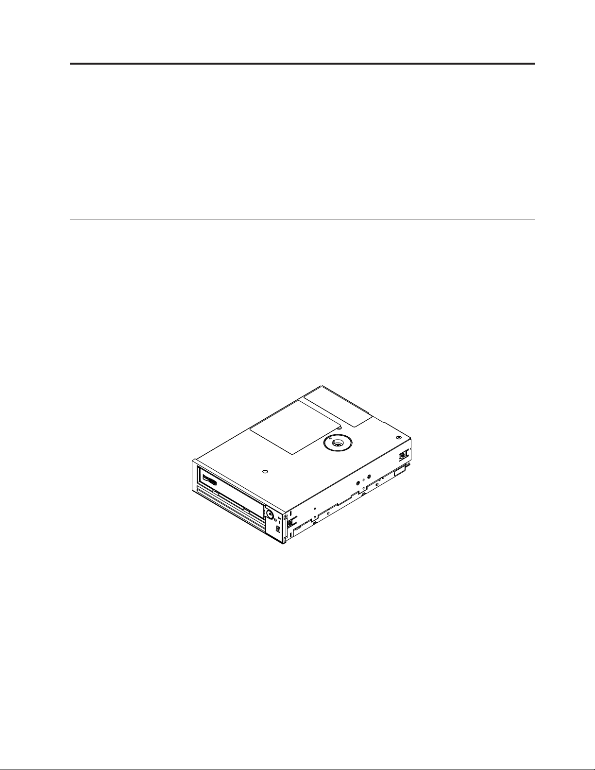
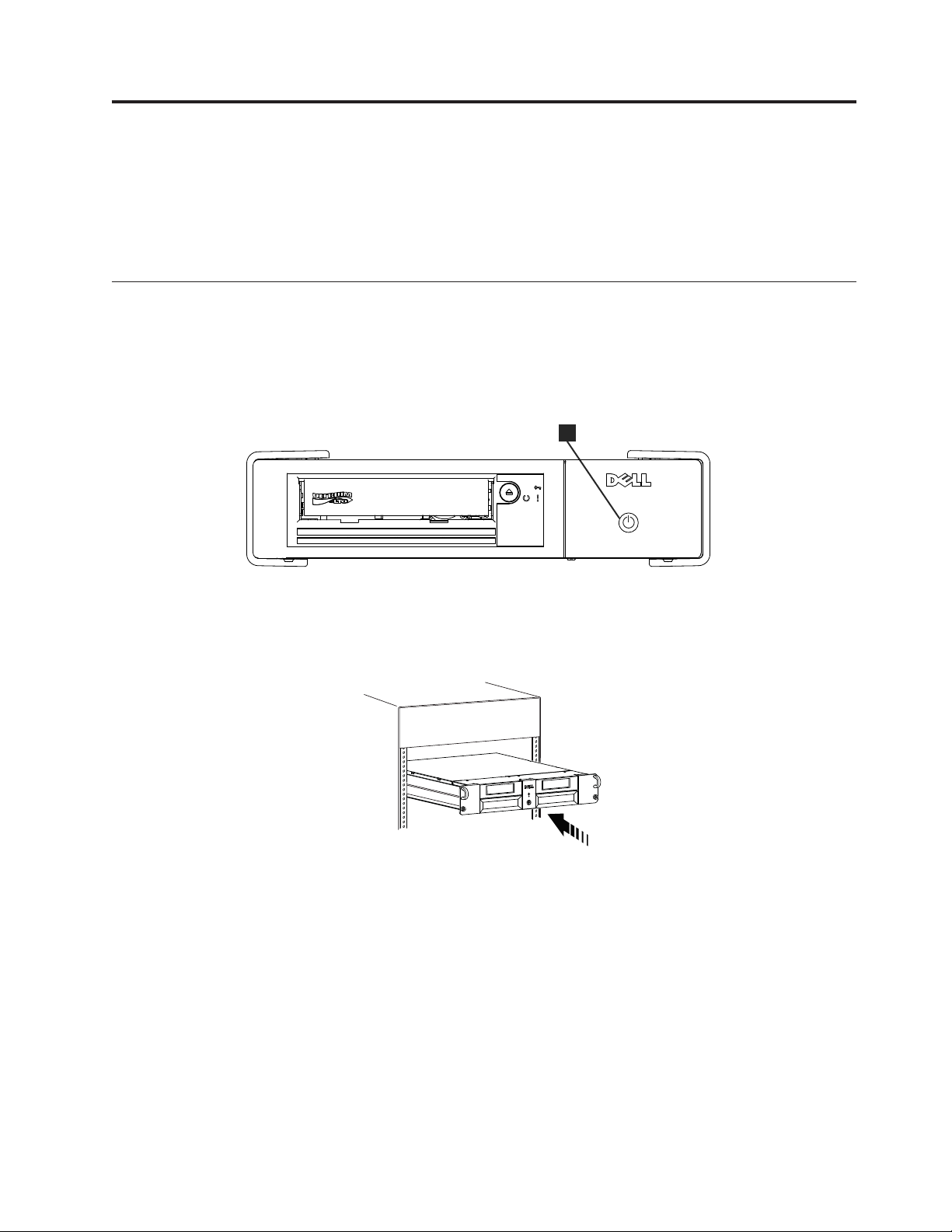
Overview
The LTO PowerVault tape drive is a high-performance, high-capacity tape storage
device that is designed to back up and restore data and archive and retrieve files
in an Open Systems environment. The drive can be integrated into a system
(internal model) or can be provided as a separately packaged desktop unit
(external model). There are six generations of the Dell PowerVault tape drives in
the LTO series of products.
Figure 1-1 shows the internal model of the tape drive. Figure 1-2 on page 1-2
shows the separately purchased external model of the tape drive. Figure 1-3 on
page 1-2 shows the rack mount model.
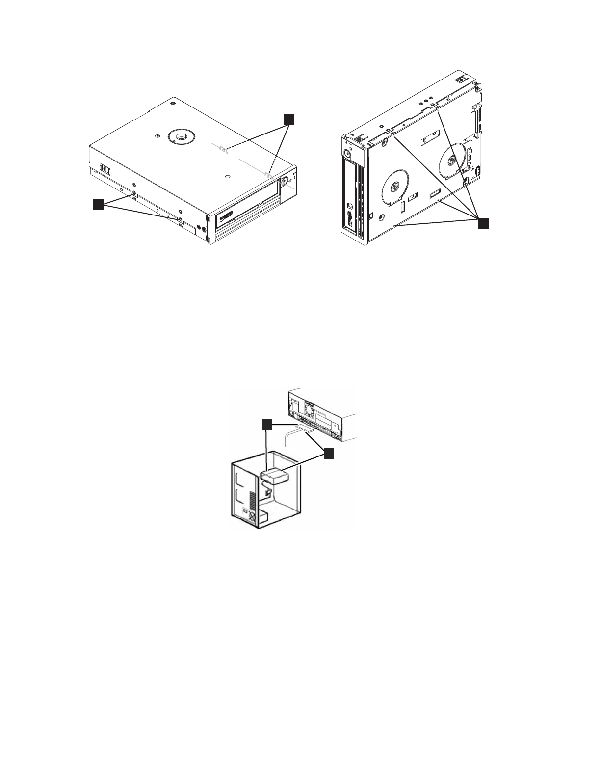
Figure 1-1. PowerVault Internal Model
a80hd004
1-1
Page 10
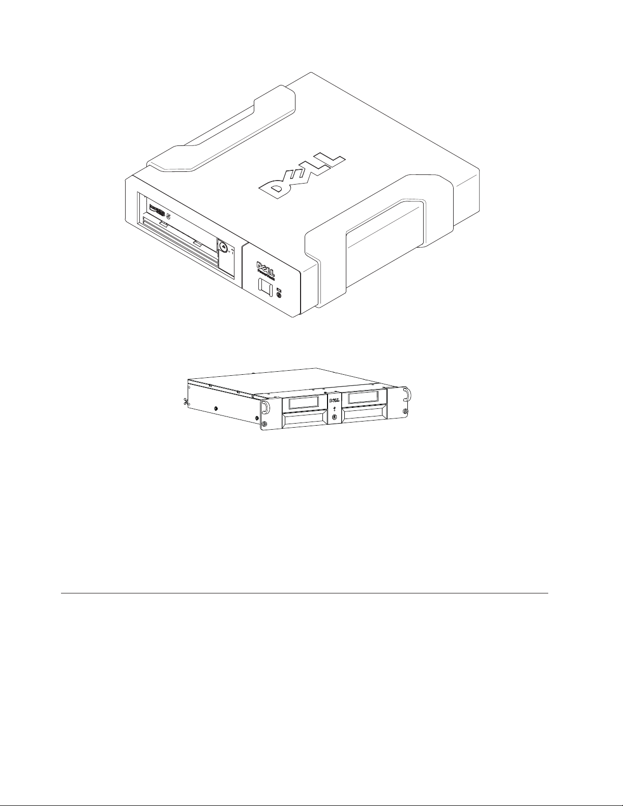
Figure 1-2. PowerVault External Model
Figure 1-3. PowerVault Rack Mount Model
Serial Attached SCSI (SAS) Interface
A drive with a SAS (Serial Attached SCSI) interface can be linked directly to
controllers. The SAS interface offers the following advantages over the traditional
SCSI interface:
v SAS enables multiple devices (up to 128) of different sizes and types to be
connected simultaneously with thinner and longer cables.
v Its full-duplex signal transmission supports up to 6.0 Gb/s.
v SAS drives can be hot-plugged.
1
a80hd00
a77ug279
Encryption
The Tape Drive has Application Managed Encryption (AME) functionality. You
must have an application that supports encryption to use the drive's encryption
capability. For more details, consult your application support documentation.
1-2 Dell PowerVault LTO Tape Drive User's Guide
Page 11

Specifications and Features
Specifications
Table 1-1. LTO Generation Specifications
Specification LTO6 LTO5-140 LTO4-120 LTO3-80
Native Capacity 2500 GB 1500 GB 800 GB 400 GB
2.5:1
Compressed
Capacity
2:1 Compressed
Capacity
Maximum
Native Data
Transfer
Compressed
Maximum Data
Transfer*
Media
Partitioning**
Data Safe
Mode**
Encryption
Status LED
PowerVault Generation
6250 GB NA NA NA
5000 GB 3000 GB 1600 GB 800 GB
160 MB/s 140 MB/s 120 MB/s 80 MB/s
400 MB/s 280 MB/s 240 MB/s 160 MB/s
X X NA NA
X X NA NA
X X NA NA
* Assumes compression. The capacity and transfer rate you realize in practice
depends on the data set, which affects the actual compression ratio. LTO6 supports
2.5:1 compression. LTO5-140 and below support 2:1 compression.
** This feature must be supported by your tape backup software.
Features
The tape drive has the following features:
v Built-in read-after-write verification for a high level of data integrity
v Burst data transfer rate of 600 MB per second
v 512 MB of read/write cache memory
v Intelligent LTO-DC dual-mode compression algorithm
v Failsafe leader capture mechanism with pin pick error recovery
v Reads cartridge memory in LTO cartridges
v TapeAlert support for improved diagnostic and troubleshooting
v Two 6 Gb Serial Attached SCSI interface
v Speed matching (The drive can slow down to match the system data rate.)
v Sleep mode for energy conservation
v Backward read and write compatibility dependent on generation
v Compatible with all cartridges dependent on generation that bears the official
Ultrium LTO logo. See Table 1-1 for more information.
Chapter 1. Introduction 1-3
Page 12
v Will interchange tapes with other LTO tape drives that bear the official Ultrium
LTO logo
v Support for WORM (Write Once Read Many) using WORM media
v Data encryption capability using LTO Ultrium 4, 5 and 6 media
v Ethernet interface for transferring drive firmware and dumps only (not an iSCSI
interface)
v Diagnostics of the drive over the ethernet service port (not an iSCSI interface)
Tape Backup Software
You need backup software that supports the Dell PowerVault tape drive. As a
general rule, native backup applications (such as NTBackup and tar) do not
provide the required data streaming rate to get the full performance of your tape
drive. It is recommend that you use a backup application that provides better
memory management as well as other useful features, such as TapeAlert. For the
latest supported software versions, go to the Dell support website at
http://support.dell.com or visit the support site of your backup software vendor.
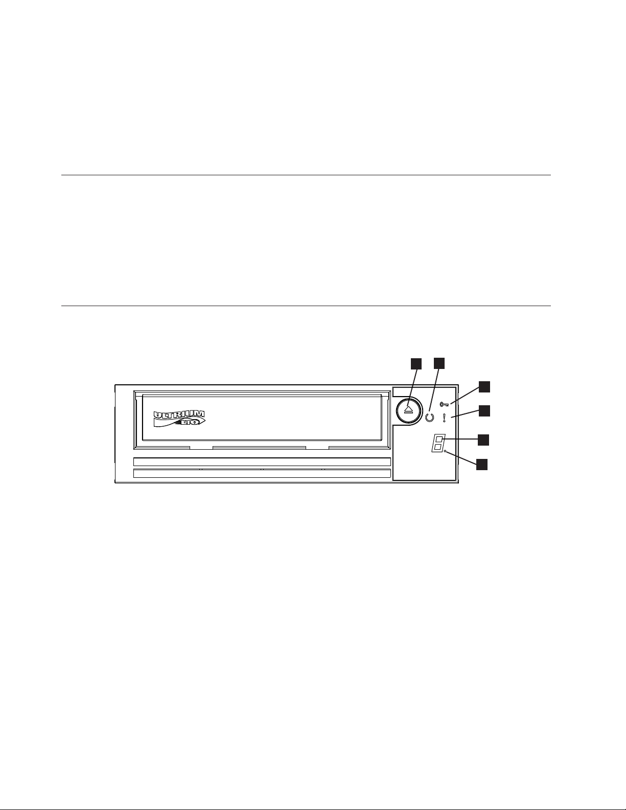
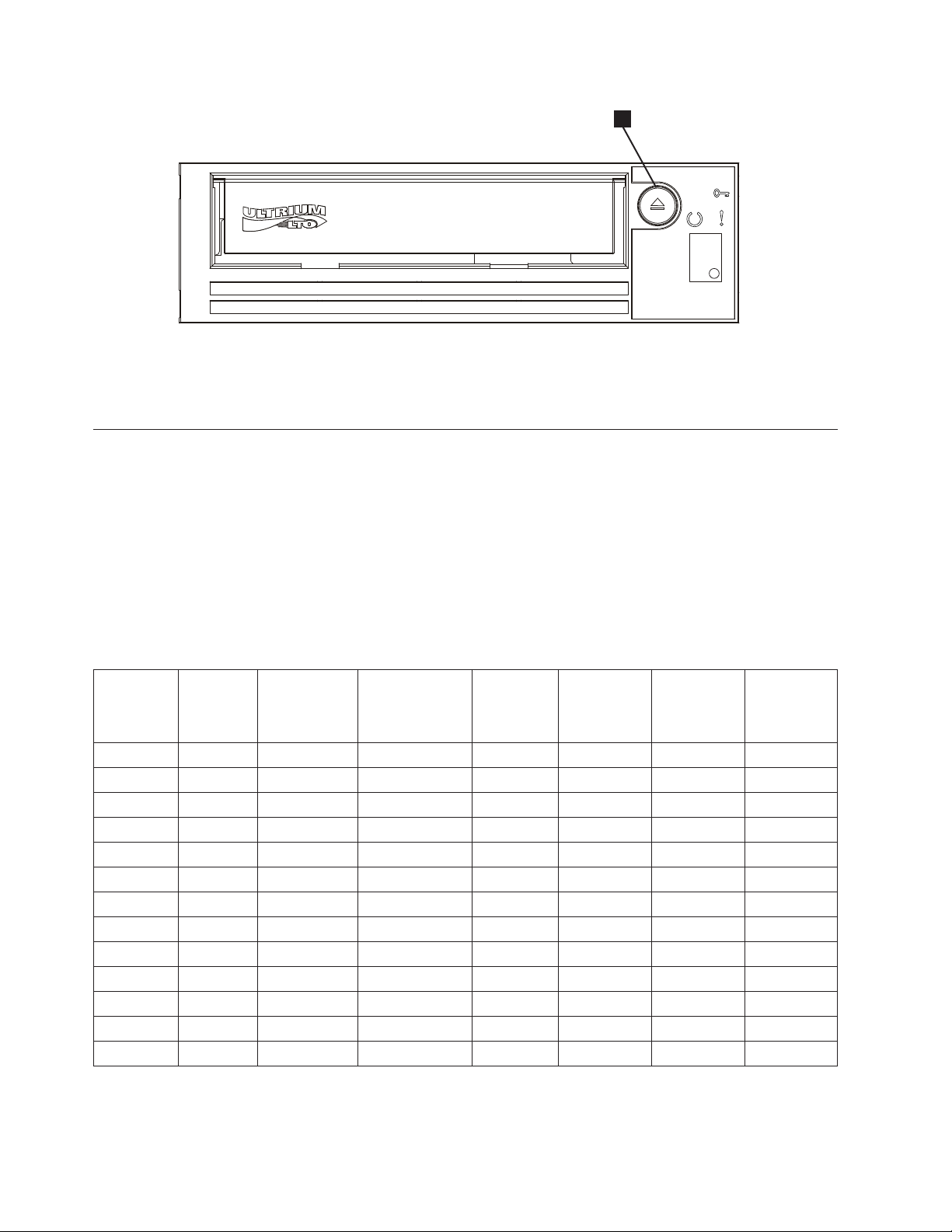
Front Panel
2
1
Figure 1-4. Front Panel
6
3
4
3
5
a80hd00
1 Eject button 4 Single-character display (SCD)
2 Ready/Activity LED 5 Single dot
3 Fault LED 6 Encryption Status LED
1. Eject button. The eject button enables you to perform several functions. These
functions are described in detail in Chapter 3, “Using the Tape Drive,” on page
3-1.
2. Ready/Activity LED. The front panel of your Dell PowerVault LTO tape drive
has a green Ready/Activity LED providing information about the state of the
tape drive. The LED can be solid on or flashing when lit. See Table 1-2 on page
1-5 for more descriptions.
3. Fault LED. The front panel of your Dell PowerVault LTO tape drive has an
amber fault LED indicating the drive has encountered an error, is not in a
normal operational status, or needs cleaning. See Table 1-2 on page 1-5 for more
detailed description.
1-4 Dell PowerVault LTO Tape Drive User's Guide
Page 13
4. Single-character display (SCD). This LED presents a single-character code for
C
C
C
diagnostic/maintenance functions, error conditions, and informational
messages.
5. Single dot. This single-character display is blank during normal operation.
When a single dot illuminates and flashes on the display, the drive has created
a dump of vital technical data to drive memory.
6. Encryption status LED. This white LED indicates all data (except for the label
information) on the cartridge is encrypted. (LTO5 and LTO6 cartridges only).
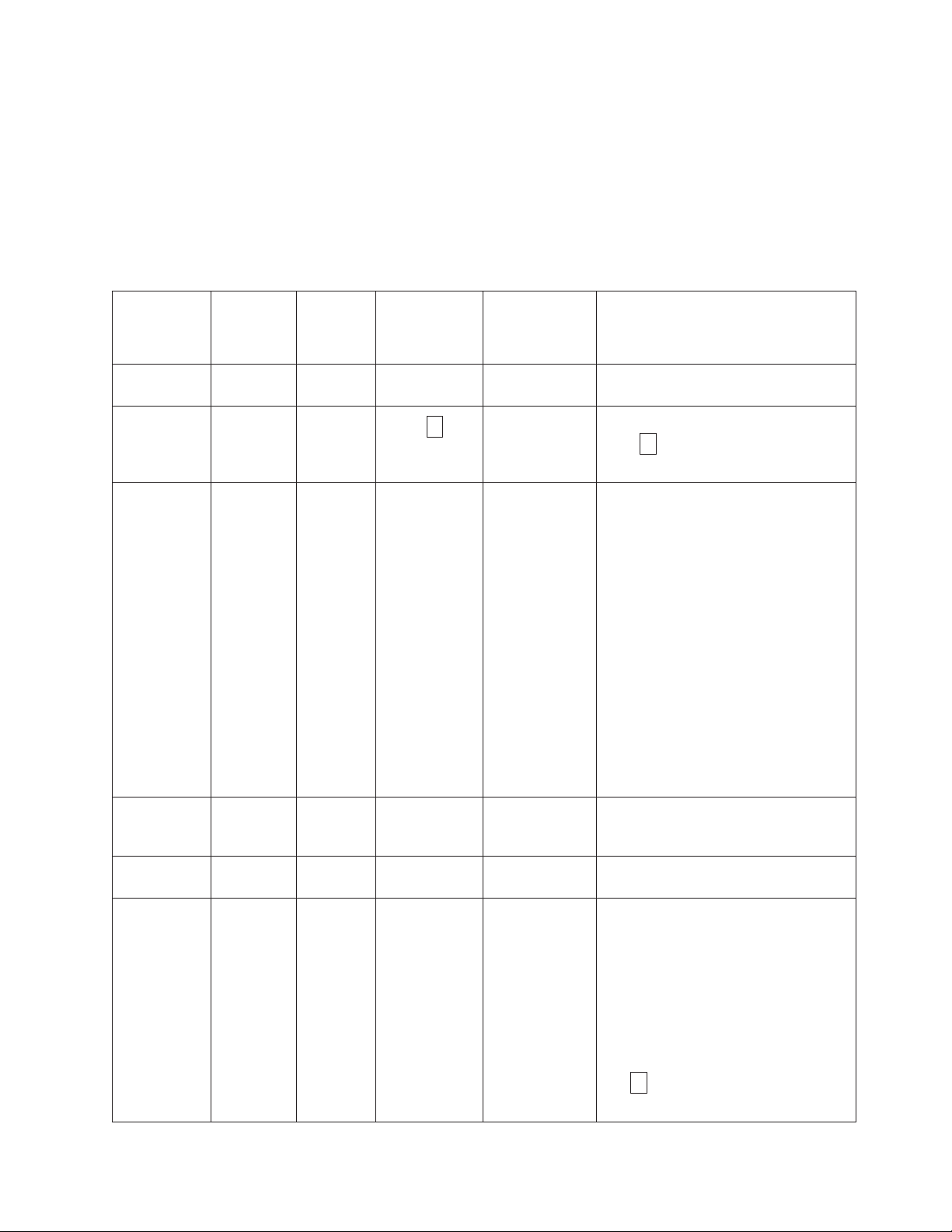
Table 1-2. SCD, Ready/Activity LED, and Fault LED Descriptions
Condition of
green
Ready/
Activity LED
Off Off Off Off Off The tape drive has no power or is
On Solid Off Off
Flashing once
per second
Off On/Solid Off On Solid On/Off The tape drive is in maintenance mode
Off On Solid Off Flashing once
Off Flashing
Condition
of amber
Fault LED
Off On or Off Off Off The tape drive is reading from the
once per
second
Condition
of white
encryption
LED
Off On Solid Off An error occurred and the tape drive
Condition of
the SCD Panel
Off or
per second
Condition of
the SCD Dot
Off The tape drive is powered on or (if a
On/Off Executing the selected option while in
Meaning of LEDs and SCD Panel and
SCD Dot
powered off.
solid
character display) needs cleaning.
tape, writing to the tape, rewinding the
tape, locating data on the tape, loading
the tape, or unloading the tape. The
Encryption LED will be On if all the
data on the cartridge is encrypted
during these drive operations. The
Ready/Activity LED also flashes green
if the tape drive contains a cartridge
during the power on cycle. In this case,
the drive completes POST and slowly
rewinds the tape (this process may take
approximately 13 minutes). The
Ready/Activity LED stops blinking
when the drive completes the recovery
and is ready for a read or write
operation. To eject the cartridge, press
the unload button.
or is displaying an error code on the
SCD in maintenance mode option 9.
maintenance mode.
or media may require service or drive
may require cleaning.
displays in the single
Note the code on the single character
display, and then go to the error code
table in the troubleshooting section to
determine the meaning of the error
codes.
If a
cleaning cartridge must be loaded.
appears on the SCD, a
Chapter 1. Introduction 1-5
Page 14
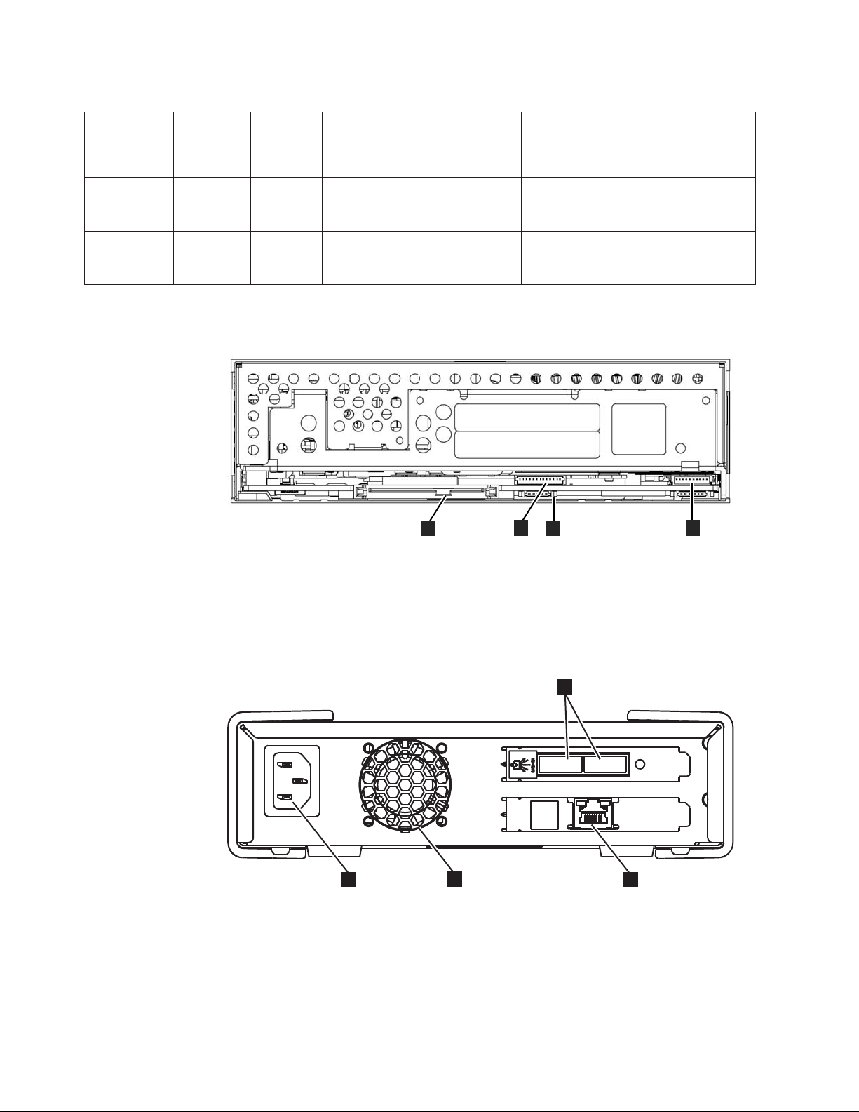
Table 1-2. SCD, Ready/Activity LED, and Fault LED Descriptions (continued)
Condition of
green
Ready/
Activity LED
Condition
of amber
Fault LED
Off Flashing
Condition
of white
encryption
LED
Condition of
the SCD Panel
Condition of
the SCD Dot
Off Off Off The drive is updating firmware.
twice per
second
Off Flashing
Off Off Off The drive detected an error and is
once every
2 seconds
Rear Panel
Meaning of LEDs and SCD Panel and
SCD Dot
performing a firmware recovery. It will
reset automatically.
2
1
4
3
Figure 1-5. Rear Panel of Internal SAS Tape Drive
1 SAS connector 3 Library interface
2 Ethernet - not iSCSI - for
4 LED controls for library drive sled
transferring firmware
and dumps only
3
1
2
4
Figure 1-6. Rear Panel of External SAS Tape Drive
1 Power connector 3 SAS connectors
2 Fan enclosure 4 Ethernet - not iSCSI - for transferring
firmware and dumps only
a80hh095
12
a80hh0
1-6 Dell PowerVault LTO Tape Drive User's Guide
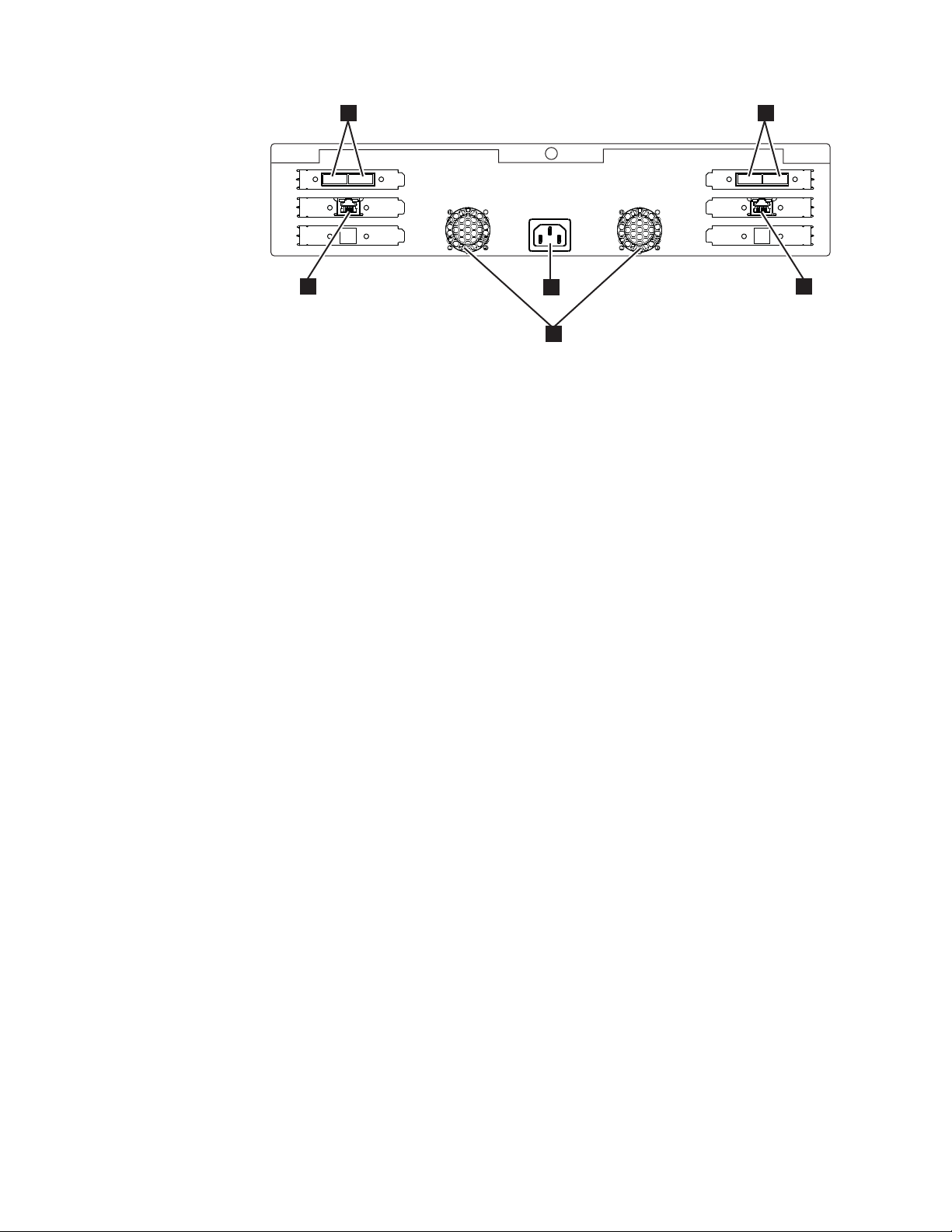
Page 15
33
4
1
4
2
Figure 1-7. Rear Panel of the Rack Mount Tape Drive
1 Power connector 3 SAS connectors
2 Fan enclosure 4 Ethernet - not iSCSI - for transferring
firmware and dumps only
a80hh089
Chapter 1. Introduction 1-7
Page 16

1-8 Dell PowerVault LTO Tape Drive User's Guide
Page 17

Chapter 2. Setting Up the Tape Drive
v “Pre-installed Internal Drives”
v “Installing Internal Drives”
– “Installing the Internal Drive - Step-By-Step Instructions”
v “Installing External and Rack Mount Drives” on page 2-5
– “Installing the External Drive - Step-By-Step Instructions” on page 2-5
v “Verifying Drive Operation” on page 2-7
v “Loading Device Drivers” on page 2-7
v “Ethernet Service Port Procedures” on page 2-8
Pre-installed Internal Drives
Dell performs the installation and setup of internal tape drives that are shipped as
part of a system. If tape backup software is included in your system, refer to the
installation instructions included with the software.
For the latest supported software versions, go to the Dell support website
http://support.dell.com or visit the support site of your backup software vendor.
Installing Internal Drives
If your internal tape drive is not pre-installed, the installation instructions are
described in the following sections:
Installing the Drive — Prerequisites
The Dell PowerVault tape drive isa6GbSASdevice with a burst transfer rate of
600 MB per second. It is recommended that you use a dedicated SAS host bus
adapter for this tape drive.
Mounting Bay
You need one industry-standard, 5 1/4 inch, half-height bay in which to install the
PowerVault tape drive. The only supported mounting configurations are
horizontally with the base of the drive parallel to the ground, or vertically with
either the left or right side of the drive parallel to the ground.
Install and configure the drive according to the instructions provided in the Dell
documentation for your system.
Mounting Hardware
Most systems use trays or rails to mount the tape drive. If the mounting hardware
is pre-installed, you can simply slide the drive into the mounting bay. Some
systems do not use slides or rails and drives must be fixed in place with screws.
Installing the Internal Drive - Step-By-Step Instructions
Procedure
1. Unpacking the Drive
2-1
Page 18
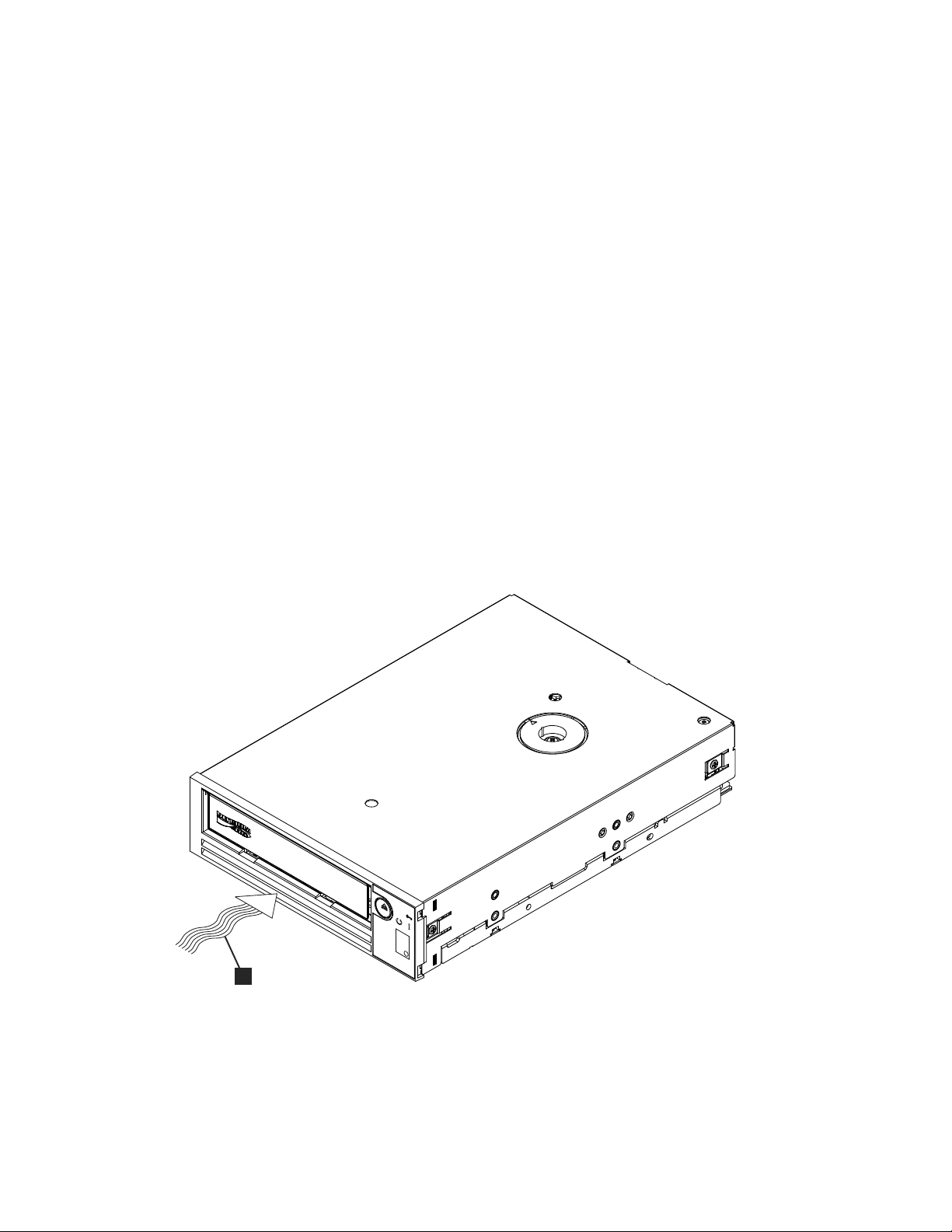
Unpack the tape drive and store the packaging. You may need the packaging if
you return the unit for service.
A period of time is required if the temperature of the drive when unpacked is
different than the temperature of its operating environment (measured at the
front of the bezel near the air intake area; see 1 in Figure 2-1). The
recommended time is 4 hours after the drive has been unpacked or 1 hour after
any condensation that you can see has evaporated, whichever is greater. To
allow the drive to adjust to its new environment, apply the following measures:
v If the drive is colder than its operating environment and the air contains
sufficient humidity, condensation may occur in the drive and damage it.
When the drive has warmed to the operating temperature range (greater
than 10 degrees C or 50 degrees F) and no danger of condensation is present
(the air is dry), warm the drive more quickly by powering it on for 30
minutes. Use a scratch tape to test the drive before inserting a tape that
contains data.
v If the drive is hotter than its operating environment, the tape can stick to the
drive head. When the drive has cooled to the operating temperature range
(less than 40 degrees C or 104 degrees F), cool the drive more quickly by
applying airflow for 30 minutes. Power on the drive and use a scratch tape
to test it before inserting a tape that contains data.
If you are uncertain about whether the temperature of the drive is within the
recommended operating range or the humidity is sufficient to cause
condensation, allow the drive to adjust to its new environment for the full 4
hours.
1
Figure 2-1. Air Intake Area
1 Air Intake Area
2. Removing Power from the System
a. Power-off the system.
b. Disconnect the power cord from both the electrical outlet and the system.
2-2 Dell PowerVault LTO Tape Drive User's Guide
a80hd002
Page 19
3. Preparing the Mounting Bay in Your System
CAUTION:
To avoid personal injury or damage to the system or tape drive, ensure that
the system power cord is disconnected before you install the drive.
Refer to your system's documentation for instructions on how to prepare the
mounting bay to receive the tape drive.
4. Attaching Mounting Hardware
If your system requires special rails or other hardware to install the tape drive,
mount them on the tape drive in this step.
If your system does not require special mounting hardware, proceed to step 5.
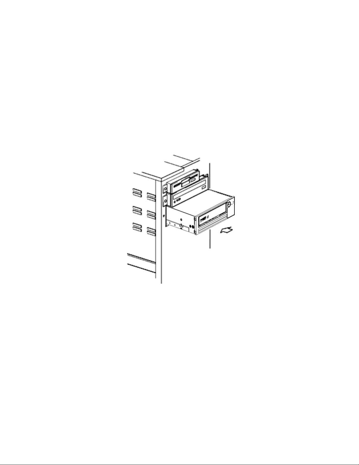
5. Installing the Drive
Slide the tape drive into the open bay, aligning the tray or rails with the slots in
the bay, as shown in Figure 2-2.
Figure 2-2. Install the Drive
6
a80hd00
If your system does not use mounting hardware, check that the holes in the
chassis are aligned with the holes in the side of the tape drive (see Figure 2-3
on page 2-4).
Chapter 2. Setting Up the Tape Drive 2-3
Page 20
1
Figure 2-3. Mounting Holes on Tape Drive
1 M-3 mounting screw holes
Do not secure the drive with screws at this point because you may have to
move the drive to get the cables in place.
6. Attaching SAS Cable
Attach the system SAS cable to the drive SAS connector, as shown in
Figure 2-4.
1
10
1
a80hh0
Figure 2-4. Attaching SAS Cable
1 SAS cable
2 Power cable
7. Securing the Drive
The tape drive can now be secured to the system as shown in Figure 2-5 on
page 2-5. There are several ways to secure the drive. If the drive is on rails or
in a sled, then push it in place. Some systems require the drive to be inserted
into a media bay and attached directly to the system with screws.
1
2
a80hh094
2-4 Dell PowerVault LTO Tape Drive User's Guide
Page 21
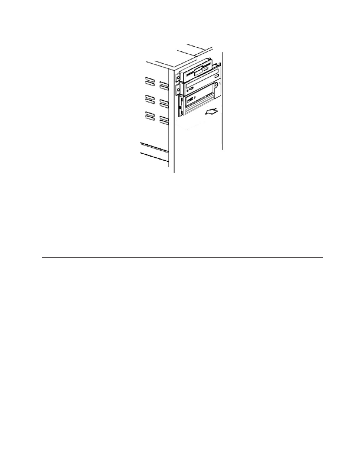
Figure 2-5. Secure the Drive
8. Connecting Host System Power and Testing Power to the Tape Drive
Connect the power cord to the system and to the electrical outlet. To ensure
that the drive is receiving power, watch for the following indicators while
turning on the power to the system:
a. The single-character display presents a series of random characters.
b. The single-character display becomes blank (not lit).
c. The Fault LED briefly turns on, then the ready/activity LED turns on solid.
Installing External and Rack Mount Drives
Installing the Drive — Prerequisites
The SAS tape drive has a burst transfer rate of 600 MB per second. It is
recommended that a dedicated host bus adapter is used for the tape drive.
Your system must have a properly installed and configured SAS host adapter or a
SAS controller on the motherboard (if available) with driver software that supports
the tape drive. Do not connect to a RAID controller channel; RAID controller
channels are for disk drives only.
a80hd007
Installing the External Drive - Step-By-Step Instructions
Procedure
1. Positioning the Tape Drive
Position the tape drive convenient to the system. The only restrictions are the
length of the power cord and the length of the SAS cable. The following
locations are recommended:
v Away from high-traffic areas, especially if the floor is carpeted.
v Out of copy rooms to avoid toner and paper dust. Do not store paper
supplies next to any unit.
v Away from moving air, such as doorways, open windows, fans, and air
conditioners.
Chapter 2. Setting Up the Tape Drive 2-5
Page 22
v Off the floor.
v Where the tape cartridge can easily be inserted.
Only the following mounting positions are supported:
v In a horizontal or vertical position for external drives.
v In a horizontal position for rack mounted drives.
Notice: The external tape drive should not be stacked. Do not place anything
on top of the unit.
2. Connecting Power
An external Dell PowerVault Tape Drive will operate using any voltage in the
range 100–240 volts (50–60 Hz). No adjustment is needed. To connect your
drive to the power supply, proceed as follows:
a. Plug the power cable securely into the socket on the rear panel of the drive.
b. Plug the other end of the power cable into a grounded power outlet.
c. Power on the tape drive by pressing the power on/off button. The tape
drive runs the POST, which checks all hardware except the drive head.
3. Connecting the SAS Cable
Attach one end of the SAS cable to the SAS host adapter card installed in the
system. Attach the other end of the SAS cable to the SAS connector on the rear
panel of the tape drive. The cable can be up to 5 m (16.4 ft) long. This
configuration is shown in Figure 2-6.
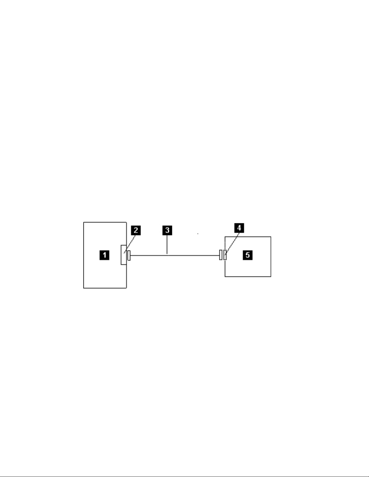
Figure 2-6. Connecting the SAS cable
1 System 4 Drive SAS connector
2 SAS host adapter card 5 Tape Drive
3 SAS cable
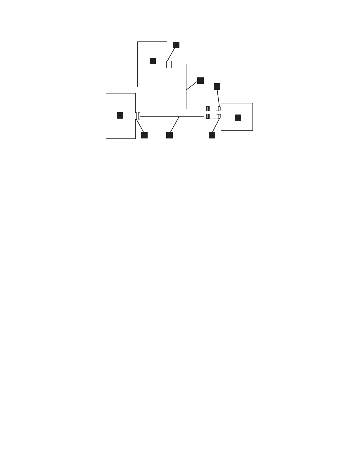
To connect a second system to the tape drive, attach one end of the second SAS
cable to the SAS host adaptor installed in the second system. Attach the other
end of the second SAS cable to the other SAS port on the rear panel of the tape
drive. This configuration is shown in Figure 2-7 on page 2-7.
2-6 Dell PowerVault LTO Tape Drive User's Guide
ltog2028
Page 23
4
5
3
2
5
4
Figure 2-7. Connecting two SAS Hosts to one Tape Drive
1 Tape Drive 4 SAS host adapter card
2 Drive shaft connector 5 System
3 SAS cable
3
Note: Unlike SCSI, the SAS architecture does not support daisy changing.
4. Configuring the Tape Drive to the Host
Power on the tape drive. Refer to your system and application software
manuals to configure the tape drive for use.
Verifying Drive Operation
After you install the drive hardware, verify that it is functioning properly before
you store your valuable data. Turn on the system. For external drives, turn on the
drive before you turn on the system.
The tape drive will run its Power-On Self Test (POST), which checks all hardware
except for the drive head. The single-character display will present a series of
random characters, and then become blank (not lit). The fault LED will flash once,
then the Ready/Activity LED will turn on solid.
1
2
a67ru043
Verify that the tape drive installation was successful. Following the instructions
given with your Tape Backup Software application, write test data to a tape, read
the test data from the tape, and compare the data read from the tape with the
original data on disk.
Loading Device Drivers
Microsoft Windows Server
This section describes how to install the Microsoft®Windows Server®Device
Drivers for the tape drive.
Notice: Some backup software applications do not require device drivers to be
loaded and, in some cases, installing device drivers could interfere with
proper functioning of the application. See the documentation for the
respective application prior to loading these drivers. The latest drivers are
available at http://support.dell.com.
Chapter 2. Setting Up the Tape Drive 2-7
Page 24

Ethernet Service Port Procedures
To update the drive’s firmware using the ethernet interface:
Note: The drive uses a limited version of FTP protocol to communicate on the
ethernet interface. It is recommended to use a simple, command line FTP
session, such as the DOS command prompt, when communicating with the
drive. This product is not intended to be connected directly or indirectly by
any means whatsoever to interfaces of public telecommunications networks.
When the IP address has been changed to the customer LAN or DHCP has
obtained a new address, the default address of the tape drive will still be
available. This does not create a LAN conflict as the customer LAN address
takes operational preference. The default address will not conflict with other
drives having the default address. When the drive comes online the drive
checks if the default address is on the LAN and will not become active
while another drive is active. This is acceptable operation and at times a
multi-drive LAN may see different drives with accessible default address.
1. Obtain the latest drive firmware from the web. Go to http://support.dell.com.
2. Connect an ethernet patch cable to the drive’s ethernet interface and to a
computer. In order to meet electromagnetic immunity requirements, a shielded
ethernet cable is required.
3. Create an FTP session between the drive and the computer. The drive’s default
IP address: 169.254.0.3.
4. At the user prompt, type guest and press Enter.
5. At the password prompt, press Enter. No response is needed.
6. Type bin to set the communication mode to binary.
7. Type put firmware name to transfer the firmware to the drive. Replace firmware
name with the actual firmware file name. The drive will reset automatically
when the transfer is complete and the FTP session will be lost. Type quit to end
the FTP session.
8. After the drive resets, the new firmware will be loaded on the drive.
9. Remove the ethernet patch cable from the drive’s ethernet interface.
Capturing a drive dump using the ethernet interface
Another way to capture a drive dump is using the ethernet port. To capture a
dump on the drive using the ethernet interface follow the steps below.
Note: The drive uses a limited version of FTP protocol to communicate on the
ethernet interface. It is recommended to use a simple, command line FTP
session, such as the DOS command prompt, when communicating with the
drive. This product is not intended to be connected directly or indirectly by
any means whatsoever to interfaces of public telecommunications networks.
1. Connect an ethernet patch cable to the drive’s ethernet interface and to a
computer. In order to meet electromagnetic immunity requirements, a shielded
ethernet cable is required.
2. Create an FTP session between the drive and the computer. The drive’s default
IP address: 169.254.0.3.
3. At the user prompt, type guest and press Enter.
4. At the password prompt, press Enter. No response is needed.
5. Type bin to set the communication mode to binary.
6. Type mget *.dmp to transfer a drive dump to the computer. If a dump already
exists, the drive will show you the dump name and ask if you want to transfer
2-8 Dell PowerVault LTO Tape Drive User's Guide
Page 25

it to the computer. Type y to transfer the existing dump or n to skip this dump
file. Then the drive will ask if you want a forced dump. Type y to force a dump
and to transfer the forced dump to the computer, or type n to skip forcing a
dump.
7. Type quit to end the FTP session.
8. Remove the ethernet patch cable from the drive’s ethernet interface.
Chapter 2. Setting Up the Tape Drive 2-9
Page 26

2-10 Dell PowerVault LTO Tape Drive User's Guide
Page 27
Chapter 3. Using the Tape Drive
v “Operating the Drive”
v “Loading, Unloading, and Write-Protecting Cartridges” on page 3-2
v “Caring for Tape Cartridges” on page 3-5
v “Cleaning the Tape Mechanism” on page 3-7
Operating the Drive
Turn on the external drive by pushing the power on/off button on the front panel
(Figure 3-1). Turn on the rack mount drive by pushing the power on/off button on
the front panel (Figure 3-2).The tape drive runs its Power-On Self-Test (POST). At
the end of the hardware self-test, the ready/activity LED must be solid green.
Figure 3-1. Turning on the External Drive
1
30
a80hd0
1 Power On/Off Button
Figure 3-2. Turning on the Rack Mount Drive
Resetting the Drive
You can reset the drive without powering off the drive and system. This may be
necessary if the drive stops responding. To do this, press and hold the eject button
on the front panel of the tape drive for 10 seconds (Figure 3-3 on page 3-2). The
drive forces a dump of vital technical data to drive memory and overwrites the
existing dump. The drive then reboots to allow communication.
3-1
Page 28
1
Figure 3-3. Resetting the Drive
1 Eject Button
Loading, Unloading, and Write-Protecting Cartridges
Use only LTO Ultrium format cartridges with your drive, as specified in the LTO
Ultrium standard. Ensure that only one label is stuck to the label area of the
cartridge. Do not use nonstandard labels, and do not stick anything to the
cartridge other than in the label area.
a80hd008
The Dell PowerVault LTO Tape Drive is compatible (see Supported Functions of
Compatible Media Types) with the cartridges of its predecessors. Below is a
description of the functions that are supported on the different compatible media
types:
Table 3-1. Supported Functions of Compatible Media Types
LTO
Cartridge
Generation
6 846 2500 6250 Yes No No No
6 WORM 846 2500 6250 Yes No No No
5 846 1500 3000 Yes Yes No No
5 WORM 846 1500 3000 Yes Yes No No
4 820 800 1600 RO Yes Yes No
4 WORM 820 800 1600 RO Yes Yes No
3 680 400 800 No RO Yes Yes
3 WORM 680 400 800 No RO Yes Yes
2 609 200 400 No No RO Yes
1 609 100 200 No No No RO
1 319 50 100 No No No RO
1 203 30 60 No No No RO
1 97 10 20 No No No RO
Tape
Length
(nominal)
(m)
Data Capacity
(native) (GB
Data Capacity
(compressed
1
)
(GB
1
)
PowerVault
2
Generation
)
LTO 6
PowerVault
Generation
LTO 5
PowerVault
Generation
LTO 4
PowerVault
Generation
LTO 3
3-2 Dell PowerVault LTO Tape Drive User's Guide
Page 29

1
1 GB = 1 000 000 000 bytes.
2
Compression Ratio
v 2.5:1 = LTO6
v 2:1 = LTO5, LTO4, and LTO3
3
RO = Read Only
Figure 3-4 shows the LTO Ultrium Data Cartridge and its components.
4
6
2
3
5
Figure 3-4. LTO Ultrium Data Cartridge
1 LTO cartridge memory 4 Insertion guide
2 Label area 5 Cartridge door
3 Write-protect switch 6 Leader pin
Loading a Tape Cartridge
1. Ensure that the tape drive is powered on. (The ready/activity LED is solid
green.)
2. Ensure that the write-protect switch (see 3 in Ultrium LTO Data Cartridge)is
properly set. (See “Setting the Write-Protect Switch on Tape Cartridges” on
page 3-4.)
3. Grasp the cartridge so that the write-protect switch faces you.
4. Slide the cartridge into the tape load compartment (see Figure 3-5 on page 3-4).
The tape drive automatically loads the cartridge.
v If the cartridge is already in the ejected position and you want to reinsert it,
remove the cartridge and then insert it again.
v If the cartridge is already loaded and you cycle the power (turn it off, then
on), the cartridge does not automatically eject. When the drive powers back
on, the cartridge is brought back to the loaded position.
1
Chapter 3. Using the Tape Drive 3-3
Page 30

Figure 3-5. Loading
a80hd009
1 Write-Protect Switch
Unloading a Tape Cartridge
1. Ensure that the tape drive is powered on. (The ready/activity LED is solid
green.)
2. Press the eject button (see 1 in Figure 3-3 on page 3-2). The drive rewinds the
tape and ejects the cartridge. The ready/activity LED flashes green while the
tape rewinds, then goes out before the cartridge ejects.
3. After the cartridge ejects, grasp the cartridge and remove it.
Whenever you unload a tape cartridge, the tape drive writes any pertinent
information to the cartridge memory.
Notice: Do not remove a tape cartridge while the drive activity indicator is on.
Setting the Write-Protect Switch on Tape Cartridges
Notice: Write-protection will not prevent a cartridge from being erased by
bulk-erasure or degaussing. Do not bulk-erase Ultrium format cartridges.
This will destroy prerecorded servo information and render the cartridge
unusable. Always use the long or quick erase command in your backup
software to erase cartridges.
The position of the write-protect switch (Figure 3-6 on page 3-5) on the tape
cartridge determines whether you can write to the tape:
v If the switch is set to locked (locked padlock), data cannot be written to the tape.
v If the switch is set to unlocked (unlocked padlock or black void), data can be
written to the tape.
3-4 Dell PowerVault LTO Tape Drive User's Guide
Page 31

Figure 3-6. Setting the Write-Protect Switch
1 Write-Protect Switch
To set the switch, slide it left or right to the desired position.
Notice: Always set the write protection tab prior to loading the cartridge into the
drive. Sliding the tab after loading will cause unpredictable results and
could result in drive errors or backup failure.
Caring for Tape Cartridges
Notice: Do not insert a damaged tape cartridge into your tape drive. A damaged
cartridge can interfere with the reliability of the drive and may void the
warranties of the drive and the cartridge. Before inserting a tape cartridge,
inspect the cartridge case, cartridge door, and write-protect switch for
breaks.
Incorrect handling or an incorrect environment can damage the LTO Ultrium Tape
Cartridge or its magnetic tape. To avoid damage to your tape cartridges and to
ensure the continued high reliability of your tape drive, use the following
guidelines.
Provide Training
v Post procedures that describe proper media handling in places where people
gather.
v Ensure that anyone who handles tape has been properly trained in handling and
shipping procedures. This includes operators, users, programmers, archival
services, and shipping personnel.
v Ensure that any service or contract personnel who perform archiving are
properly trained in media-handling procedures.
v Include media-handling procedures as part of any services contract.
v Define and make personnel aware of data recovery procedures.
Ensure Proper Packaging
v When you ship a cartridge, ship it in its original or similar packaging.
v Always ship or store a cartridge in a jewel case.
v Use only a recommended shipping container that securely holds the cartridge in
its jewel case during transportation.
Chapter 3. Using the Tape Drive 3-5
Page 32

v Never ship a cartridge in a commercial shipping envelope. Always place it in a
box or package.
v If you ship the cartridge in a cardboard box or a box of a sturdy material, ensure
the following:
– Place the cartridge in polyethylene plastic wrap or bags to protect it from
dust, moisture, and other contaminants.
– Pack the cartridge snugly; do not allow it to move around.
– Double-box the cartridge (place it inside a box, then place that box inside the
shipping box) and add padding between the two boxes.
Provide Proper Acclimation and Environmental Conditions
v Before you use a cartridge, let it acclimate to the normal operating environment
for 1 hour. If you see condensation on the cartridge, wait an additional hour.
v Ensure that all surfaces of a cartridge are dry before inserting it.
v Do not expose the cartridge to moisture or direct sunlight.
v Do not expose recorded or blank cartridges to stray magnetic fields of greater
than 100 oersteds (for example, terminals, motors, video equipment, X-ray
equipment, or fields that exist near high-current cables or power supplies). Such
exposure can cause the loss of recorded data or make the blank cartridge
unusable.
v Maintain the following environmental conditions outlined in Table 3-2.
Table 3-2. Environmental Specifications
Environmental
Factor
Temperature 10° to 45°C
Relative
humidity
(noncondensing)
Wet bulb
temperature
1
Operational storage equals less than 1 year.
2
Archival storage equals 1 to 10 years.
Operating Operational
Storage
16° to 35°C
(50° to 113°F)
10% to 80% 20% to 80% 20% to 50% 5% to 80%
26°C (79°F) 26°C (79°F) 26°C (79°F) 26°C (79°F)
(61° to 95°F)
1
Archival
Storage
16° to 25°C
(61° to 77°F)
2
Shipping
-23° to 49°C
(-9° to 120°F)
Perform a Thorough Inspection
v Inspect the cartridge's packaging to determine potential rough handling.
v When inspecting a cartridge, open only the cartridge door. Do not open any
other part of the cartridge case. The upper and lower parts of the case are held
together with screws; separating them destroys the usefulness of the cartridge.
v Inspect the cartridge for damage before using or storing it.
v Inspect the rear of the cartridge (the part that you load first into the tape load
compartment) and ensure that there are no gaps in the seam of the cartridge
case. If there are gaps in the seam, the leader pin may be dislodged.
v Check that the leader pin is properly seated.
v If you suspect that the cartridge has been mishandled but it appears useable,
copy any data onto a good cartridge immediately for possible data recovery.
Discard the mishandled cartridge.
v Review handling and shipping procedures.
3-6 Dell PowerVault LTO Tape Drive User's Guide
Page 33

Handle the Cartridge Carefully
C
C
7
7
v Do not drop the cartridge. If the cartridge drops, slide the cartridge door back
and ensure that the leader pin is properly seated in the pin-retaining spring
clips.
v Do not handle tape that is outside the cartridge. Handling the tape can damage
the tape's surface or edges, which may interfere with read or write reliability.
Pulling on tape that is outside the cartridge can damage the tape and the brake
mechanism in the cartridge.
v Do not stack more than six cartridges.
v Do not degauss a cartridge that you intend to reuse. Degaussing makes the tape
unusable.
Cleaning the Tape Mechanism
Dell PowerVault drives have been developed to have a minimal cleaning
requirement. The tape drive will display a
the fault LED will flash amber when the drive needs cleaning. Only insert a
cleaning cartridge into the tape drive when the
Notice: Only use LTO cleaning cartridges that are labeled "universal." The tape
drive is only compatible with the LTO Ultrium universal cleaning
cartridges. Use of any other type of cleaning cartridge or method can
damage the read/write head in your drive. If you load any other type of
cleaning cartridge, the tape drive displays a
the cartridge until it is ejected manually by pressing the Eject button.
An LTO Ultrium universal cleaning cartridge is supplied with each tape drive. Do
not use swabs or other means of cleaning the heads. The cleaning cartridge uses a
special tape to clean the tape heads.
Though the number may vary according to the manufacturer, the universal
cleaning cartridge is generally valid for 50 separate cleaning operations. If you try
to use the cleaning cartridge beyond 50 separate cleaning operations, an error code
of
one.
To use the LTO Ultrium universal cleaning cartridge:
1. Insert a cleaning cartridge into the tape drive. The tape drive performs the
2. Remove the cleaning cartridge from the drive.
will be displayed. Eject the cleaning cartridge and replace it with a new
cleaning automatically. When the cleaning is finished, the drive ejects the
cartridge.
on the single-character display and
is displayed.
in the SCD and retains
Chapter 3. Using the Tape Drive 3-7
Page 34

3-8 Dell PowerVault LTO Tape Drive User's Guide
Page 35

Chapter 4. Using the Tape Backup Software
See the User's Operating Guide supplied with your Tape Backup application for
more information about using the Tape Backup software. For the latest supported
software versions, go to the Dell support website at http://support.dell.com or
visit the support site of your backup software vendor.
4-1
Page 36

4-2 Dell PowerVault LTO Tape Drive User's Guide
Page 37

Chapter 5. Troubleshooting
v “Obtaining Drivers and Firmware Upgrades”
v “Selecting a Diagnostic or Maintenance Function”
v “General Guidelines” on page 5-8
v “Methods of Receiving Errors and Messages” on page 5-9
v “Descriptions and Corrective Actions” on page 5-10
v “Drive Status” on page 5-13
v “Drive Maintenance” on page 5-14
v “Fixing SAS Connectivity Problems” on page 5-15
v “Resolving Media-Related Problems” on page 5-16
v “Removing an Internal SAS Tape Drive” on page 5-16
v “TapeAlert” on page 5-17
v “Recovering a Tape Cartridge” on page 5-20
Obtaining Drivers and Firmware Upgrades
Notice: When updating firmware, do not power off the tape drive until the update
is complete, or the firmware may be lost.
For information on the latest versions of firmware, see the Dell support website at
http://support.dell.com.
Selecting a Diagnostic or Maintenance Function
The tape drive can run diagnostics, test write and read functions, test a suspect
tape cartridge, and perform other diagnostic and maintenance functions. The drive
must be in maintenance mode to perform these functions. To place the drive in
maintenance mode and select a diagnostic or maintenance function, see the
Diagnostic and Maintenance Function Codes and Descriptions table.
Note: The host interface on this tape drive is Serial Attached SCSI (SAS). This
interface presents SCSI protocol to the tape drive. In this User's Guide,
references to SCSI relate to SCSI protocol, not the serial interface that it is
transmitted over.
Note: You cannot perform maintenance functions concurrently with read or write
operations. While in maintenance mode, the tape drive does not accept SCSI
commands from the system. Close all tape drive applications before entering
maintenance mode.
5-1
Page 38

Table 5-1. Diagnostic and Maintenance Function Codes and Descriptions
1
1
C
C
P
1
0
F
Function Code1-RunTapeDrive Diagnostics
Causes the tape drive to run self tests.
Attention: Insert only a scratch data cartridge for this test. Data on the cartridge will be overwritten.
1. Ensure that there is no cartridge in the drive.
2. Press the eject button three times within an interval of 2 seconds. The fault LED becomes solid amber, which
means that the drive is in maintenance mode.
3. Press the eject button once per second until
continue to press the eject button until it reappears.
4. To select the function, press and hold the eject button for 3 seconds. After you select the function,
the drive runs diagnostics for approximately 90 seconds, then
waiting for a cartridge.
5. Within 60 seconds, insert a scratch data cartridge that is not write-protected.
Note: If you wait longer than 60 seconds to load a cartridge, the drive automatically exits maintenance mode. If
you insert a write-protected cartridge, the tape drive displays a
ejected. When the cartridge is ejected and removed, the tape drive exits maintenance mode.
After you insert the cartridge,
v The diagnostic test takes approximately 5 minutes to run. The tape drive will unload and load the cartridge
during the test. Do not try to remove the cartridge when it unloads the first time. Wait for the test to
complete.
v If the diagnostic completes successfully, the cartridge ejects, the single-character display flashes a
goes blank, and the drive exits maintenance mode. If the diagnostic fails, the fault LED flashes and an error
code displays. When the cartridge is manually ejected and removed, the tape drive automatically exits
maintenance mode.
v To halt the diagnostic and terminate the test, press the eject button twice anytime during the test. The drive
flashes and the test begins.
appears in the single-character display. If you cycle past1,
flashes,
flashes. When
and retains the cartridge until it is manually
flashes, the drive is
, then
acknowledges the request by slowing the flash rate of the
second to once per second. The tape drive rewinds and unloads the cartridge and then exits maintenance
mode.
Function Code 2 — RESERVED (Service Function)
Function Code 3 — RESERVED (Service Function)
on the single-character display from twice per
5-2 Dell PowerVault LTO Tape Drive User's Guide
Page 39

Table 5-1. Diagnostic and Maintenance Function Codes and Descriptions (continued)
8
8
0
9
0
0
Function Code 4 — Force a Dump of Vital Data to Tape Drive Memory
Causes the tape drive to perform a collection (or dump) of vital technical data and save it to drive memory. (A
drive dump is also known as a save of the firmware trace.)
Notice: When an error code is displayed in maintenance mode, the tape drive also displays a dot to remind you
that a dump already exists. If you perform Function Code 4, it will overwrite the dump and cause the error
information to be lost.
1. Ensure that there is no cartridge in the drive.
2. Press the eject button three times within an interval of 2 seconds. The fault LED becomes solid amber, which
means that the drive is in maintenance mode.
3. Press the eject button once per second until
continue to press the eject button until it reappears.
4. To select the function, press and hold the eject button for 3 seconds. After you select the function,
followed by
You can also perform this operation when the tape drive is in normal operating mode. Simply press and hold the
eject button for 10 seconds.
Function Code5-RESERVED (Service Function)
Function Code6-RESERVED (Service Function)
Function Code7-RESERVED (Service Function)
Function Code8-RESERVED (Service Function)
Function Code9-Display Error Code Log
Causes the tape drive to display the last ten error codes, one at a time. (The codes are ordered; the most recent is
presented first and the oldest (tenth) is presented last.)
To view the drive error log:
1. Ensure that there is no cartridge is in the drive.
2. Within a 2 second interval press the eject button three times. The fault LED becomes solid amber, which means
that the drive is in maintenance mode.
3. Press the eject button once per second until
4. Press and hold the eject button for 3 seconds to view the most recent error code.
5. Refer to “Descriptions and Corrective Actions” on page 5-10 to determine the meaning of the code and the
action to take.
6. Press the eject button to view the next error code. (The codes are ordered; the most recent is presented first and
the oldest (tenth) is presented last.)
. The single-character display then goes blank, and the tape drive exits maintenance mode.
appears in the single-character display. If you cycle past8,
displays,
appears in the single-character display.
7. Continue to press the eject button until
been encountered or the log has just been cleared, a
maintenance mode. A maximum of ten error codes are stored.
To redisplay the error codes, repeat steps 1 through 7.
appears, indicating that no more error codes exist. If no errors have
will appear immediately and the drive will exit
Chapter 5. Troubleshooting 5-3
Page 40

Table 5-1. Diagnostic and Maintenance Function Codes and Descriptions (continued)
A
0
6or7
E
C
C
E
6or7
Function Code A - Clear Error Code Log
Causes the tape drive to erase the contents of the error code log.
1. Ensure that there is no cartridge in the drive.
2. Press the eject button three times within an interval of 2 seconds. The fault LED becomes solid amber, which
means that the drive is in maintenance mode.
3. Press the eject button once per second until
continue to press the eject button until it reappears.
4. To select the function, press and hold the eject button for 3 seconds. After you select the function, the tape drive
erases all errors from the error code log, displays
Function Code C - Insert Cartridge Into Tape Drive
This function cannot be selected by itself. It relates to other maintenance functions (such as Run Tape Drive
Diagnostics) that require a scratch tape cartridge that is not write protected.
Function CodeE-TestCartridge & Media
Causes the tape drive to perform a Write/Read test (on the edge bands) to ensure that a suspect cartridge and its
magnetic tape are acceptable. The tape drive takes approximately 15 minutes to run one loop of the test. The test
loops ten times before completing.
v If no error is detected, the test begins again and runs for a maximum of ten times. After the tenth loop, the test
stops and the drive automatically exits maintenance mode.
v If an error is detected, the tape drive displays
manually ejected and removed, the tape drive exits maintenance mode.
v To halt the diagnostic at the end of the current 15 minute test loop, press the eject button once. The drive
acknowledges the request by slowing the length of time that the currently displayed character flashes on the
single-character display (from twice per second to once per second). The diagnostic continues to the end of its
loop and then stops. The tape drive then rewinds, unloads the cartridge, and exits maintenance mode.
v To halt the diagnostic immediately and terminate the test that is running, press the eject button twice. The tape
drive rewinds, unloads the cartridge, and exits maintenance mode.
appears in the single-character display. If you cycle pastA,
, then exits maintenance mode.
in the single-character display. Once the cartridge is
Attention: Data on the suspect tape will be overwritten.
1. Ensure that there is no cartridge in the drive.
2. Press the eject button three times within an interval of 2 seconds. The fault LED becomes solid amber, which
means that the drive is in maintenance mode.
3. Press the eject button once per second until
continue to press the eject button until it reappears.
4. To select the function, press and hold the eject button for 3 seconds. After you select the function,
When
the tape drive exits maintenance mode). After you insert the cartridge,
v If no error is detected, the test begins again and runs for a maximum of ten times. After the tenth loop, the
test stops and the drive automatically exits maintenance mode. To halt the test, press the eject button. The
tape drive then rewinds and unloads the cartridge, displays0, and exits maintenance mode.
v If an error is detected, the tape drive displays
removed, the tape drive exits maintenance mode.
flashes, the drive is waiting for a cartridge. Within 60 seconds, insert the suspect data cartridge (or
appears in the single-character display. If you cycle pastE,
flashes.
flashes and the test begins.
. Once the cartridge is manually ejected and
5-4 Dell PowerVault LTO Tape Drive User's Guide
Page 41

Table 5-1. Diagnostic and Maintenance Function Codes and Descriptions (continued)
F
C
C
F
Function CodeF-Write Performance Test
Causes the tape drive to perform tests to ensure that the drive can read from and write to tape. This diagnostic
performs fewer tests than the Run Tape Drive Diagnostics test (Function Code 1). The tape drive takes
approximately 3 minutes to run the test. The Fast Read/Write Test is not as comprehensive a test and is not
recommended for isolating errors between the drive and the media.
Attention: Data on the suspect tape will be overwritten.
1. Ensure that there is no cartridge in the drive.
2. Press the eject button three times within an interval of 2 seconds. The fault LED becomes solid amber, which
means that the drive is in maintenance mode.
3. Press the eject button once per second until
continue to press the eject button until it reappears.
4. To select the function, press and hold the eject button for 3 seconds. After you select the function,
When
the tape drive exits maintenance mode). After you insert the cartridge,
v If no error is detected, the test begins again and runs for a maximum of ten times. Each loop takes
approximately 3 minutes to run. After the tenth loop, the test stops and the drive automatically exits
maintenance mode.
v If an error is detected, the tape drive displays an error code. Once the cartridge is manually ejected and
removed, the tape drive exits maintenance mode.
v To halt the diagnostic at the end of the current 3 minute test loop, press the eject button once. The drive
acknowledges the request by slowing the length of time that the currently displayed character flashes on the
single-character display (from twice per second to once per second.) The diagnostic continues to the end of its
loop and then stops. The tape drive then rewinds, unloads the cartridge, and exits maintenance mode.
v To halt the diagnostic immediately and terminate the test that is running, press the eject button twice. The
tape drive rewinds, unloads the cartridge, and exits maintenance mode.
flashes, the drive is waiting for a cartridge. Within 60 seconds, insert the suspect data cartridge (or
appears in the single-character display. If you cycle pastF,
flashes and the test begins.
flashes.
Chapter 5. Troubleshooting 5-5
Page 42

Table 5-1. Diagnostic and Maintenance Function Codes and Descriptions (continued)
H
C
C
H
5
Function Code H - Test Head
Causes the tape drive to perform the Head Resistance Measurements test and a Write/Read test (on the center of
the tape). The drive runs these tests to ensure that the tape drive's head and tape-carriage mechanics are working
correctly. The tape drive takes approximately 10 minutes to run the test.
1. Ensure that there is no cartridge in the drive.
2. Press the eject button three times within an interval of 2 seconds. The fault LED becomes solid amber, which
means that the drive is in maintenance mode.
3. Press the eject button once per second until
continue to press the eject button until it reappears.
4. To select the function, press and hold the eject button for 3 seconds. After you select the function,
When
tape drive exits maintenance mode). After you insert the cartridge,
v If no error is detected, the test begins again and runs for a maximum of ten times. Each loop takes
approximately 10 minutes to run. After the tenth loop, the test stops and the drive automatically exits
maintenance mode.
v If an error is detected, the tape drive displays
v To halt the diagnostic at the end of the current 10 minute test loop, press the eject button once. The drive
acknowledges the request by slowing the length of time that the currently displayed character flashes on the
single-character display (from twice per second to once per second). The diagnostic continues to the end of its
loop and then stops. The tape drive then rewinds, unloads the cartridge, and exits maintenance mode.
v To halt the diagnostic immediately and terminate the test that is running, press the eject button twice. The
tape drive then rewinds, unloads the cartridge, and exits maintenance mode.
flashes, the drive is waiting for a cartridge. Within 60 seconds, insert a scratch data cartridge (or the
appears in the single-character display. If you cycle pastH,
flashes and the test begins.
, unloads the tape cartridge, and exits maintenance mode.
flashes.
5-6 Dell PowerVault LTO Tape Drive User's Guide
Page 43

Table 5-1. Diagnostic and Maintenance Function Codes and Descriptions (continued)
P
7
Function Code J - Fast Read/Write Test
Approximate Run Time=5minutes
Total Number of Loops = 10
J
Function Code
The diagnostic loops ten times. Press the eject button to stop the diagnostic and exit maintenance mode. Pressing
the eject button once will abort the test at the end of the current test loop. Pressing the eject button twice will abort
the test immediately.
Attention: For this test, insert only a scratch (blank) data cartridge or a cartridge that may be overwritten. During
the test, the drive overwrites the data on the cartridge.
1. Ensure that there is no cartridge in the drive.
2. Press the eject button three times within an interval of 2 seconds. The fault LED becomes solid amber, which
means that the drive is in maintenance mode.
3. Press the eject button once per second until
continue to press the eject button until it reappears.
4. Press and hold the eject button for three or more seconds, then release it to select the function. The
single-character display changes to a flashingC.
5. Within 60 seconds, insert a scratch data cartridge that is not write-protected.
Note: If you wait longer than 60 seconds to load a cartridge, the drive will automatically exit maintenance
performs tests to ensure that the drive can read from and write to tape.
J
appears in the single-character display. If you cycle pastJ,
mode. If you insert a write-protected cartridge, the tape drive will display a
is manually ejected. Once the cartridge is ejected and removed, the tape drive will exit maintenance mode.
After you insert the cartridge, the single-character display changes to a flashing
tests.
Note: If you inserted an invalid cartridge, error code
retains the cartridge until it is manually ejected. Once ejected, the tape drive exits maintenance mode.
v If no error is detected, the test will loop and begin again. To stop the loop, press the eject button for one second
and release. When the loop ends, the drive rewinds, unloads the tape, and exits maintenance mode.
v If an error is detected, the fault LED flashes amber, then the tape drive posts an error code to the single-character
display. To determine the error, locate the code in “Descriptions and Corrective Actions” on page 5-10. Once the
cartridge is manually ejected and removed, the tape drive exits maintenance mode.
appears in the single-character display. The tape drive
and retain the cartridge until it
J
, and the tape drive runs the
Chapter 5. Troubleshooting 5-7
Page 44

Table 5-1. Diagnostic and Maintenance Function Codes and Descriptions (continued)
L
L
P
L
0
7
7
Function Code L - Load/Unload Test
Approximate Run Time = 15 seconds per loop
Total Number of Loops = 10
Function Code
The diagnostic loops ten times. To stop the diagnostic and exit maintenance mode, press the eject button once to
abort the test.
Attention: The diagnostic loops ten times. To stop the diagnostic and exit maintenance mode, press the eject
button once to abort the test.
1. Ensure that there is no cartridge in the drive.
2. Press the eject button three times within an interval of 2 seconds. The fault LED becomes solid amber, which
means that the drive is in maintenance mode.
3. Press the eject button once per second until
continue to press the eject button until it reappears.
4. Press and hold the eject button for three or more seconds, then release it to select the function. The
single-character display changes to a flashingC.
5. Within 60 seconds, insert a scratch data cartridge that is not write-protected.
Note: If you wait longer than 60 seconds to load a cartridge, the drive will automatically exit maintenance
mode. If you insert a write-protected cartridge, the tape drive will display a
is manually ejected. Once the cartridge is ejected and removed, the tape drive will exit maintenance mode.
After you insert the cartridge, the single-character display changes to a flashing
v If no error is detected, the test will loop and begin again. To stop the loop, press the eject button for one second
tests the drive's ability to load and unload a tape cartridge.
appears in the single-character display. If you cycle pastL,
and retain the cartridge until it
. The tape drive runs the tests.
and release. When the loop ends,
tape and unloads the cartridge. The drive then exits maintenance mode.
v If an error is detected the test stops,
in “Descriptions and Corrective Actions” on page 5-10. The drive unloads the tape cartridge and exits
maintenance mode. To clear the error, turn the tape drive power off, then on again.
Function Code P or U - RESERVED (Service Function)
temporarily appears in the single-character display. The drive rewinds the
appears in the single-character display. To determine the error, locate
General Guidelines
If you encounter problems when running the Dell PowerVault Tape Drive, refer to
Table 5-2 for common problems. If the problem is not identified, refer to “Methods
of Receiving Errors and Messages” on page 5-9. The color and condition of the
LEDs may also indicate a problem.
Table 5-2. General Troubleshooting
If the problem is this... Do this...
A code displays on the single-character display and the
fault LED flashes amber.
The tape drive detected an error or is directing you to an
informational message. See “Methods of Receiving Errors
and Messages” on page 5-9.
5-8 Dell PowerVault LTO Tape Drive User's Guide
Page 45

Table 5-2. General Troubleshooting (continued)
If the problem is this... Do this...
The ready/activity LED or single-character display never
turns on.
The tape drive does not load a tape cartridge. One of the following has occurred:
The tape drive does not unload the tape cartridge. The tape cartridge is stuck or is broken. Press the eject
The system received TapeAlert flags. See Table 5-5 on page 5-17.
The system reported system problems (such as selection
or command time-outs, or parity errors).
Codes display on the single-character display, but the
ready/activity LED does not turn on.
The tape drive does not respond to system commands. Press and hold the eject button on the drive for 10
The tape drive has no power. Check the power at the
power source. Connect power to the tape drive. If the
problem persists, contact Dell technical support.
v A tape cartridge is already loaded. To remove the
cartridge, press the eject button. If the cartridge does
not eject, turn off the power to the tape drive, then
turn it back on. After the ready/activity LED becomes
solid green, press the eject button to eject the cartridge.
v The cartridge tray may not be in the correct position.
Press the eject button to return the tray to the correct
position.
v The tape cartridge was loaded incorrectly. To properly
load a cartridge, see the Loading section in “Loading,
Unloading, and Write-Protecting Cartridges” on page
3-2.
v The tape cartridge may be defective. Load another
tape cartridge. If the problem exists for multiple
cartridges, the tape drive is defective. Contact Dell
technical support.
v The tape drive has no power. Connect power to the
tape drive.
button. If the cartridge does not eject, turn off the power
to the tape drive, and then turn it back on. (Note that the
mid-tape recovery could take up to 10 minutes to
complete.) If the cartridge still does not eject, manually
remove it (see “Recovering a Tape Cartridge” on page
5-20).
See “Fixing SAS Connectivity Problems” on page 5-15.
The tape drive is defective. Contact Dell technical
support.
seconds to force a drive dump. The drive will save the
dump and then reboot to allow communication to the
drive to occur. Do not cycle power, as this will erase the
contents of the dump.
Methods of Receiving Errors and Messages
Use Table 5-3 on page 5-10 as a guide for identifying error codes and message
codes reported by the tape drive, its computer (if applicable), or the system.
Note: The codes on the single-character display have different meanings,
depending on whether they display during normal operations or while the
drive is in maintenance mode. Codes that occur during normal operations
are defined in “Descriptions and Corrective Actions” on page 5-10. Codes
that occur while in maintenance mode are defined in “Selecting a Diagnostic
or Maintenance Function” on page 5-1
Chapter 5. Troubleshooting 5-9
Page 46

Table 5-3. Methods of Receiving Errors and Messages
0
0
1
If the error or message was presented by... Do this...
The system's display (if the tape drive is enclosed in a
library or autoloader)
The tape drive's single-character display and the fault
LED flashes amber
The tape drive's single-character display and the fault
LED is solid amber
SCSI log sense data (such as TapeAlert flags) or SCSI
drive sense data
The tape drive's error log See “Descriptions and Corrective Actions.”
Refer to the documentation for the system.
See “Descriptions and Corrective Actions.” To determine
the meaning of the LED, see the “Front Panel” on page
1-4 section in the Introduction.
See “Selecting a Diagnostic or Maintenance Function” on
page 5-1. To determine the meaning of the fault LED
activity, see the “Front Panel” on page 1-4 section in the
Introduction.
See Table 5-5 on page 5-17 or “Descriptions and
Corrective Actions.”
Descriptions and Corrective Actions
Table 5-4 gives descriptions of the errors and messages that pertain to the tape
drive, and tells what to do when you receive them.
Notice: If the tape drive detects a permanent error and displays an error code
other than
, it automatically performs a dump of vital data to drive
memory. If you force a dump, the existing dump will be overwritten and
data will be lost. After you force a dump, do not turn off the power to the
tape drive or you may lose the dump data.
Table 5-4. Descriptions and Corrective Actions
The single-character display clears if you power-off the drive.
Code Cause and Action
No error occurred and no action is required. This code displays:
v When power is cycled (turned off, then on) to the tape drive
v When diagnostics have finished running and no error occurred
Note: The single-character display is blank during normal operation of the tape drive.
Cooling problem. The tape drive detected that the recommended operating temperature was
exceeded. Perform the following action:
1. If a fan is present in the system, ensure that it is rotating and is quiet. If not, replace the
fan. (For instructions about replacing the fan, see your system's documentation.)
2. Remove any blockage that prevents air from flowing freely through the tape drive.
3. Ensure that the operating temperature and airflow is within the specified range (see
Chapter 6, “Specifications,” on page 6-1).
4. If the proper voltages are being applied but the problem persists, contact Dell technical
support.
The error code clears when you power-off the tape drive or place it in maintenance mode.
5-10 Dell PowerVault LTO Tape Drive User's Guide
Page 47

Table 5-4. Descriptions and Corrective Actions (continued)
8
3
8
5
6
Power problem. The tape drive detected that the externally supplied power is either
approaching the specified voltage limits (the drive is still operating) or is outside the
specified voltage limits (the drive is not operating). Perform the following action:
1. Ensure that the power connector is properly seated.
2. Ensure that the proper DC voltages are being applied within the tolerances allowed (see
Chapter 6, “Specifications,” on page 6-1).
3. If the proper voltages are being applied but the problem persists, contact Dell technical
support.
The error code clears when you power-off the tape drive or place it in maintenance mode.
Firmware problem. The tape drive determined that a firmware error occurred. Perform the
following action:
1. Power the tape drive off and on, then retry the operation that produced the error. The
error code clears when you power-off the tape drive or place it in maintenance mode.
2. If the problem persists, download the latest firmware and retry the operation.
Firmware or tape drive problem. The tape drive determined that a firmware or tape drive
hardware failure occurred. Perform the following action:
1. Power the tape drive off and on, then retry the operation that produced the error. The
error code clears when you power-off the tape drive or place it in maintenance mode.
2. If the problem persists, download the latest firmware and retry the operation; if new
firmware is not available, contact Dell technical support.
Tape drive hardware problem. The drive determined that a tape path or read/write error
occurred. To prevent damage to the drive or tape, the drive will not allow you to insert a
cartridge if the current cartridge was successfully ejected. The error code may clear when you
cycle power to the tape drive or place it in maintenance mode. If the problem persists,
contact Dell technical support.
Tape drive or media error. The drive determined that an error occurred, but it cannot isolate
the error to faulty hardware or to the tape cartridge. Perform the appropriate action, as
described below.
v If the operation succeeds, the original cartridge was defective. Copy data from the
defective cartridge and discard it.
v If the operation fails and another drive is available, insert the cartridge into the other drive
and retry the operation.
– If the operation fails, discard the defective cartridge.
– If the operation succeeds, insert a scratch cartridge into the first drive and run the tape
drive diagnostics (see Function Code 1 in “Selecting a Diagnostic or Maintenance
Function” on page 5-1).
- If the diagnostics fail, contact Dell technical support.
- If the diagnostics succeed, the error was temporary.
v If the operation fails and another drive is not available, insert a scratch cartridge into the
drive and run the tape drive diagnostics (see Function Code 1 in “Selecting a Diagnostic or
Maintenance Function” on page 5-1).
– If the diagnostics fail, contact Dell technical support.
– If the diagnostics succeed, discard the cartridge.
Chapter 5. Troubleshooting 5-11
Page 48

Table 5-4. Descriptions and Corrective Actions (continued)
6
7
For Problems with Writing Data:
, continued
If the problem occurred while the drive was writing data to the tape, and if you know the
volume serial number (located on the cartridge label) of the tape cartridge loaded in the drive
when the problem occurred, retry the operation with a different cartridge:
If the problem occurs with multiple tape cartridges or if you do not know the tape cartridge's
volume serial number, run the tape drive diagnostics (see Function Code 1 in “Selecting a
Diagnostic or Maintenance Function” on page 5-1):
v If the diagnostics fail, contact Dell technical support.
v If the diagnostics succeed, run the Test Head diagnostic (see Function Code H in “Selecting
a Diagnostic or Maintenance Function” on page 5-1).
– If the Test Head diagnostic fails, contact Dell technical support.
– If the Test Head diagnostic succeeds, replace the cartridges that caused the problem.
The error code clears when you remove the tape cartridge or place the drive in maintenance
mode.
If the problem occurred while the drive was reading data from the tape, and if you know the
volume serial number of the tape cartridge, perform one of the following procedures:
v If another drive is available, insert the cartridge into the other drive and retry the
operation:
– If the operation fails, discard the defective cartridge.
– If the operation succeeds, insert a scratch cartridge into the first drive and run the tape
drive diagnostics (see Function Code 1 in “Selecting a Diagnostic or Maintenance
Function” on page 5-1):
- If the diagnostics fail, contact Dell technical support.
- If the diagnostics succeed, the error was temporary.
v If another drive is not available, insert a scratch cartridge into the drive and run the tape
drive diagnostics (see Function Code 1 in “Selecting a Diagnostic or Maintenance
Function” on page 5-1)
– If the diagnostics fail, contact Dell technical support.
– If the diagnostics succeed, discard the cartridge
For Problems with Reading Data:
If the problem occurs with multiple tape cartridges or if you do not know the tape cartridge's
volume serial number, run the tape drive diagnostics (see Function Code 1 in “Selecting a
Diagnostic or Maintenance Function” on page 5-1):
v If the diagnostics fail, contact Dell technical support.
v If the diagnostics succeed, run the Test Head diagnostic (see Function Code H in “Selecting
a Diagnostic or Maintenance Function” on page 5-1).
– If the Test Head diagnostic fails, contact Dell technical support.
– If the Test Head diagnostic succeeds, replace the cartridges that caused the problem.
The error code clears when you remove the tape cartridge or place the drive in maintenance
mode.
A high probability of media error. The tape drive determined that an error occurred because
of a faulty tape cartridge. Try another tape cartridge. If the problem occurs with multiple tape
cartridges, see “Resolving Media-Related Problems” on page 5-16. This error will also appear
if you are loading an expired cleaner cartridge.
The error code clears when you remove the tape cartridge or place the drive in maintenance
mode.
5-12 Dell PowerVault LTO Tape Drive User's Guide
Page 49

Table 5-4. Descriptions and Corrective Actions (continued)
8
9
A
b
C
d
E
F
P
Tape drive or interface failure. The tape drive determined that a failure occurred in the tape
drive's hardware or in the bus. See “Fixing SAS Connectivity Problems” on page 5-15. The
error code clears 10 seconds after the drive detected the error or when you place the drive in
maintenance mode.
Library to drive interface (RS-422) error. This interface is not used in the PowerVault tape
drive.
Tape drive hardware problem. The tape drive determined that a problem occurred that
degraded the operation of the tape drive, but it did not restrict continued use. If the problem
persists, contact Dell technical support. The drive is usable, though the single-character
display continues to indicate an error and the fault LED flashes amber.
The error code may clear when you cycle power to the tape drive or place it in maintenance
mode.
No error or message is assigned.
The tape drive needs to be cleaned. Clean the tape drive. See the “Cleaning the Tape
Mechanism” on page 3-7 section.
The error code clears when you clean the tape drive or place it in maintenance mode.
No error or message is assigned.
Not applicable for a SAS drive.
J
Drive Status
Not applicable for a SAS drive.
Incompatible media. The tape drive detected that an unsupported cartridge was loaded.
Verify that the generation of the loaded cartridge is supported on the tape drive.
Write protect. A write operation has been attempted to a write-protected cartridge or an
overwrite has been attempted to a WORM cartridge. These operations are not allowed.
Encryption Error. The drive detected a configuration or setup error prior to an encryption
operation.
The eject button is depressed. Verify that the button pushes freely.
Mid-Tape Recovery. The SCD flashes one segment at a time to complete one figure-eight
motion, then flashes the number 9, then flashes one segment at a time to complete one
figure-eight motion, then flashes the number 8. This continues until the number 1 flashes and
the drive completes. You can eject the cartridge once the count down has ended by hitting
the eject button.
1. Connect an ethernet cable to the LTO6 drive or bridgebox.
2. Using a web browser, connect to http://169.254.0.3. The drive status page will
be displayed.
Chapter 5. Troubleshooting 5-13
Page 50

Figure 5-1. Drive Status page
3. Check the appropriate box(es) to get information on that topic.
a67ru053
Figure 5-2. Drive Status page - details
Note: The page format can be changed to text-only mode by checking the box
at the top of the page.
4. Use the web browser refresh button to update the page with the current drive
status.
Drive Maintenance
1. Connect an ethernet cable to the LTO6 drive or bridgebox.
5-14 Dell PowerVault LTO Tape Drive User's Guide
a67ru054
Page 51

2. Using a web browser, connect to http://169.254.0.3/service.html. The drive
maintenance page will be displayed.
Figure 5-3. Drive Maintenance page
3. Check the appropriate radio button, then press Run to run that maintenance
function. If the drive is in a library, many of the maintenance functions are
disabled. To cancel the maintenance function press Cancel. These are the same
maintenance functions that are executed via the unload button on the drive's
front panel.
Note: For more information on Maintenance Function details, see “Selecting a
Diagnostic or Maintenance Function” on page 5-1.
Fixing SAS Connectivity Problems
If there appears to be a problem connecting or communicating with the drive,
follow this procedure.
1. Ensure that the power is on to the tape drive.
2. Replace the SAS cable and interposers, if any, and retry the failing operation.
a67ru052
Chapter 5. Troubleshooting 5-15
Page 52

3. If these measures do not correct the problem, contact Dell customer support.
6or7
Resolving Media-Related Problems
To resolve problems that are related to media, the tape drive's firmware includes:
v Test Cartridge & Media diagnostic that verifies whether a suspect cartridge and
its magnetic tape are acceptable for use.
v Statistical Analysis and Reporting System (SARS) to assist in isolating failures
between media and hardware. To determine the cause of failure, SARS uses the
cartridge performance history that is saved in the cartridge memory (CM) and
the drive performance history that is kept in the drive's Vital Product Data
(VPD) area in Non Volatile Random Access Memory (NVRAM). Any failures
that SARS detects are reported as TapeAlert flags on the system (see Table 5-5 on
page 5-17).
If you encounter a media-related problem, use the following procedure:
Notice: When you run the Test Cartridge & Media diagnostic, data on the suspect
tape is overwritten. If valuable data is on the tape, be sure to copy the
data before running this test.
1. If possible, run the tape cartridge in a different tape drive. If the operation in
the other tape drive fails and
operation succeeds, run the Test Cartridge & Media diagnostic (see Function
Code E in “Selecting a Diagnostic or Maintenance Function” on page 5-1).
2. If the Test Cartridge & Media diagnostic fails, replace the media. If it runs
successfully, clean the tape drive and run the tape drive diagnostics (see the
“Cleaning the Tape Mechanism” on page 3-7 section and Function Code 1 in
“Selecting a Diagnostic or Maintenance Function” on page 5-1).
3. If the tape drive diagnostics fail, contact Dell technical support. If the tape
drive diagnostics run successfully, perform the operation that produced the
initial media error.
Removing an Internal SAS Tape Drive
To remove an internal SAS tape drive from the system, perform the following
steps:
1. Ensure that the tape drive does not contain a tape cartridge.
2. De-configure the drive from the system. (For instructions, see your system's
documentation.)
3. Turn off the power to the system. Disconnect the power cable from the system
and the electrical outlet.
4. Remove the system cover.
5. Disconnect the internal SAS cable from the tape drive (see number 1 in
Figure 1-5 on page 1-6).
6. Remove the tape drive from the system and remove any mounting screws or
rails from the side or bottom of the tape drive.
7. To reassemble, reverse these steps.
displays, replace the media. If the
5-16 Dell PowerVault LTO Tape Drive User's Guide
Page 53

TapeAlert
TapeAlert is a patented technology and standard of the American National
Standards Institute (ANSI) that defines conditions and problems that are
experienced by tape drives. The technology enables a system to read TapeAlert
flags from a tape drive through the SCSI interface. The system reads the flags from
Log Sense Page 0x2E.
TapeAlert Flags
Table 5-5 lists the TapeAlert flags that are supported by the Dell PowerVault Tape
Drive.
Table 5-5. TapeAlert Flags and Descriptions
TapeAlert Flags Supported by the Tape Drive
Flag
Number
3 03h Hard error Set for any unrecoverable
4 04h Media Set for any unrecoverable
5 05h Read failure Set for any unrecoverable
6 06h Write failure Set for any unrecoverable
8 08h Not data grade Set when severe servo errors
Flag Parameter
(in hex)
Flag Description Action Required
read, write, or positioning
error. (This flag is set in
conjunction with flags 4, 5, or
6.)
read, write, or positioning
error that is due to a faulty
tape cartridge.
read error where isolation is
uncertain and failure could
be due to a faulty tape
cartridge or to faulty drive
hardware.
write or positioning error
where isolation is uncertain
and failure could be due to a
faulty tape cartridge or to
faulty drive hardware.
occur while loading a tape
cartridge.
See the Action Required
column for Flag 4, 5, or 6 in
this table.
Contact Dell technical
support.
If Flag 4 is also set, the
cartridge is defective. Contact
Dell technical support. If Flag
4 is not set, see error code 6
in “Descriptions and
Corrective Actions” on page
5-10.
If Flag 9 is also set, make
sure that the write-protect
switch is set so that data can
be written to the tape (see
the “Setting the Write-Protect
Switch on Tape Cartridges”
on page 3-4 section.) If Flag 4
is also set, the cartridge is
defective. Replace the tape
cartridge. If Flag 4 is not set,
see error code 6 in
“Descriptions and Corrective
Actions” on page 5-10.
Replace the tape cartridge. If
this error occurs with
multiple tapes, see error code
6 in “Descriptions and
Corrective Actions” on page
5-10.
Chapter 5. Troubleshooting 5-17
Page 54

Table 5-5. TapeAlert Flags and Descriptions (continued)
TapeAlert Flags Supported by the Tape Drive
9 09h Write protect Set when the tape drive
detects that the tape
cartridge is write-protected.
10 0Ah No removal Set when the tape drive
receives an UNLOAD
command after the system
prevented the tape cartridge
from being removed.
11 0Bh Cleaning media Set when you load a cleaning
cartridge into the drive.
12 0Ch Unsupported format Set when you load an
unsupported cartridge type
into the drive or when the
cartridge format has been
corrupted.
15 0Fh Cartridge memory chip
failure
16 10h Forced eject Set when you manually
18 12h Tape directory
corrupted in the
cartridge memory
20 14h Clean now Set when the tape drive
21 15h Clean periodic Set when the drive detects
22 16h Expired clean Set when the tape drive
23 17h Invalid cleaning tape Set when the drive expects a
Set when a cartridge memory
(CM) failure is detected on
the loaded tape cartridge.
unload the tape cartridge
while the drive was reading
or writing.
Set when the drive detects
that the tape directory in the
cartridge memory has been
corrupted.
detects that it needs cleaning.
that it needs routine cleaning.
detects a cleaning cartridge
that has expired.
cleaning cartridge and the
loaded cartridge is not a
cleaning cartridge.
Make sure that the
cartridge's write-protect
switch is set so that the tape
drive can write data to the
tape (see the “Setting the
Write-Protect Switch on Tape
Cartridges” on page 3-4
section).
Refer to the documentation
for your system's operating
system.
No action required.
Use a supported tape
cartridge.
Replace the cartridge. If this
error occurs on multiple
tapes, see error code 6 in
“Descriptions and Corrective
Actions” on page 5-10.
No action required.
Reread all data from the tape
to rebuild the tape directory.
Clean the tape drive. See the
“Cleaning the Tape
Mechanism” on page 3-7
section.
Clean the tape drive as soon
as possible. The drive can
continue to operate, but you
should clean the drive soon.
See the “Cleaning the Tape
Mechanism” on page 3-7
section.
Replace the cleaning
cartridge.
Use a valid cleaning
cartridge.
5-18 Dell PowerVault LTO Tape Drive User's Guide
Page 55

Table 5-5. TapeAlert Flags and Descriptions (continued)
TapeAlert Flags Supported by the Tape Drive
30 1Eh Hardware A Set when a hardware failure
occurs that requires that you
reset the tape drive to
recover.
31 1Fh Hardware B Set when the tape drive fails
its internal self tests.
32 20h Interface Set when the tape drive
detects a problem with the
SCSI or LDI (RS-422)
interface.
33 21h Eject media Set when a failure occurs that
requires you to unload the
cartridge from the drive.
34 22h Download fail Set when a field microcode
replacement (FMR) image is
unsuccessfully downloaded
to the tape drive via the SAS
interface.
36 24h Drive temperature Set when the drive's
temperature sensor indicates
that the drive's temperature
is exceeding the
recommended temperature of
the system (see Chapter 6,
“Specifications,” on page
6-1).
37 25h Drive voltage Set when the drive detects
that the externally supplied
voltages are either
approaching the specified
voltage limits or are outside
the voltage limits (see
Chapter 6, “Specifications,”
on page 6-1).
39 27h Diagnostics required Set when the drive detects a
failure that requires
diagnostics to isolate the
problem.
51 33h Tape directory invalid
at unload
Set when the tape directory
on the tape cartridge that
was previously unloaded is
corrupted. The file-search
performance is degraded.
If resetting the drive does not
recover the error, use the
error code from the
single-character display,
library user interface, or SCSI
drive sense data. See
“Descriptions and Corrective
Actions” on page 5-10.
Use the error code on the
single-character display,
library user interface, or SCSI
drive sense data. See
“Descriptions and Corrective
Actions” on page 5-10.
Locate error code 8 or 9 in
“Descriptions and Corrective
Actions” on page 5-10.
Unload and reload the tape
cartridge.
Ensure that it is the correct
image. Download the FMR
image again.
See error code 1 in
“Descriptions and Corrective
Actions” on page 5-10.
See error code 2 in
“Descriptions and Corrective
Actions” on page 5-10.
See error code 6 in
“Descriptions and Corrective
Actions” on page 5-10.
Rebuild the tape directory by
reading all the data.
Chapter 5. Troubleshooting 5-19
Page 56

Table 5-5. TapeAlert Flags and Descriptions (continued)
TapeAlert Flags Supported by the Tape Drive
52 34h Tape system area write
failure
53 35h Tape system area read
failure
Recovering a Tape Cartridge
If problem-determination procedures identify the tape drive as the source of the
problem and you are unable to eject the tape cartridge using the eject button,
perform the following steps to reset the drive to recover the cartridge:
1. Press and hold the eject button for 10 seconds, then release.
v The fault LED turns on and the drive starts through its hardware test
process.
v When the hardware test completes, the ready/activity LED turns on.
v If a cartridge is in the drive, the ready/activity LED flashes green and the
SCD flashes moving in a figure eight pattern until the cartridge is rewound.
v The ready/activity LED turns on solid and the SCD stops flashing in a figure
eight pattern when the rewind is complete and the tape drive is ready.
Set when the tape cartridge
that was previously
unloaded could not write its
system area successfully.
Set when the tape system
area could not be read
successfully at load time.
Copy the data to another
tape cartridge, then discard
the old cartridge
Copy the data to another
tape cartridge, then discard
the old cartridge
Note: Allow at least 10 minutes for the rewind process to complete.
2. To eject the cartridge, push the eject button one more time. If the tape cartridge
still will not eject, contact trained service personnel for assistance.
Notice: If you are not a trained service person, do not attempt to open the
drive for repairs as this will void your warranty.
5-20 Dell PowerVault LTO Tape Drive User's Guide
Page 57

Chapter 6. Specifications
v “General Specifications”
v “Internal Drive”
v “External Drive” on page 6-2
v “Rack Mount Drive” on page 6-3
General Specifications
Table 6-1. General specifications
General
Manufacturer Manufactured for Dell
Model Number (Internal, External, RackMount Dell PowerVault Tape Drive
LTO Ultrium 6-H, LTO Ultrium5-H
LTO Ultrium 4-H
LTO Ultrium 3-H
CSEH 001, LTO4-EH1, LTO3-EH1
2U Storage Rack A
Interface Type 6Gb SAS interface
Internal Drive
Table 6-2. Internal Drive specifications
Physical Specifications
Width (without bezel) 146.0 mm (5.75 in)
Width (with bezel) 148.0 mm (5.83 in)
Length (without bezel) 205.0 mm (8.09 in)
Length (with bezel) 210.0 mm (8.29 in)
Height (without bezel) 41.0 mm (1.63 in) without bezel
Height (with bezel) 42.7 mm (1.69 in) with bezel
Weight (without a cartridge) 1.61 kg (3 lb 9 oz)
Power Supply Requirements
Tolerance + 5 VDC and + 12 VDC (plus or minus 10%)
Steady State Current for 5 VDC 1.9 A minimum/3.4 A maximum
Steady State Current for 12 VDC 0.2 A minimum/1.1 A maximum
Peak supply current for 5 VDC 3.6 A for 100 ms (18 W)
Peak supply current for 12 VDC 4.1 A for 2 ms (49.2 W)
Power Usage
Idle mode with no cartridge 6.5 W
Idle mode with a cartridge loaded 6.5 W
Reading and writing 24 W
6-1
Page 58

Table 6-2. Internal Drive specifications (continued)
Physical Specifications
Performance
Interfaces 6Gb SAS
Recording format LTO Ultrium Generation
Media LTO Ultrium
Capacity LTO6-2500 GB (Native) 6250 GB (compressed, assuming
2.5:1 compression)
LTO5-1500 GB (Native) 3000 GB (compressed, assuming
2:1 compression)
LTO4-800 GB (Native) 1600 GB (compressed, assuming
2:1 compression)
LTO3-400 GB (Native) 800 GB (compressed, assuming 2:1
compression)
Data transfer rate (maximum) LTO6-160 MB/sec Native
LTO5-140 MB/sec Native
LTO4-120 MB/sec Native
LTO3-80 MB/sec Native
Burst transfer rate up to 600 MB/sec for SAS
Operating Limits
Temperature 10° to 38°C (50° to 100°F)
Humidity 20% to 80% relative humidity (non-condensing)
Maximum wet bulb temperature 26°C (79°F)
Non-operating Limits (Storage)
Temperature -40° to 60° (-40° to 140°F)
Humidity 10% to 90% relative humidity (noncondensing)
Maximum wet bulb temperature 26°C (79°F)
External Drive
Table 6-3. External Drive specifications
Physical Specifications
Width 22.2 cm (8.74 in)
Length 32.7 cm (12.87 in)
Height 6.5 cm (2.56 in)
Weight 4.4 kg (9.7 lb)
Power Requirements
AC line voltage 100 - 240 VAC
Line frequency 50–60 Hz, auto-ranging
Line current at 100 VAC 0.48 A
Line current at 240 VAC 0.20 A
6-2 Dell PowerVault LTO Tape Drive User's Guide
Page 59

External Drive Specifications, continued
Performance
Interface 6Gb SAS
Recording format LTO Ultrium Generation
Media LTO Ultrium
Capacity LTO6-2500 GB (Native) 6250 GB (compressed, assuming
2.5:1 compression)
LTO5-1500 GB (Native) 3000 GB (compressed, assuming
2:1 compression)
LTO4-800 GB (Native) 1600 GB (compressed, assuming
2:1 compression)
LTO3-400 GB (Native) 800 GB (compressed, assuming 2:1
compression)
Data transfer rate (maximum) LTO6-160 MB/sec Native
LTO5-140 MB/sec Native
LTO4-120 MB/sec Native
LTO3-80 MB/sec Native
Burst transfer rate up to 600 MB/sec for SAS
Operating Limits
Temperature 10° to 38°C (50° to 100°F)
Humidity 20% to 80% relative humidity (non-condensing)
Maximum wet bulb temperature 26°C (79°F)
Non-operating Limits (Storage)
Temperature -40° to 60° (-40° to 140°F)
Humidity 10% to 90% relative humidity (noncondensing)
Maximum wet bulb temperature 26°C (79°F)
Rack Mount Drive
Table 6-4. Rack Mount drive specifications
Physical Specifications
Width 48.3 cm (19.0 in)
Length 44.0 cm (17.32 in)
Height 9.0 cm (3.54 in)
Weight 10.23 kg (22.55 lb) Chassis empty
Power Requirements
AC line voltage 100–240 VAC
Line frequency 50–60 Hz, auto-ranging
Line current at 100 VAC 1.9 A
Line current at 240 VAC 0.8 A
Performance
Interface 6Gb SAS
Recording format LTO Ultrium Generation
Chapter 6. Specifications 6-3
Page 60

Table 6-4. Rack Mount drive specifications (continued)
Physical Specifications
Media LTO Ultrium
Capacity LTO6-2500 GB (Native) 6250 GB (compressed, assuming
2.5:1 compression)
LTO5-1500 GB (Native) 3000 GB (compressed, assuming
2:1 compression)
LTO4-800 GB (Native) 1600 GB (compressed, assuming
2:1 compression)
LTO3-400 GB (Native) 800 GB (compressed, assuming 2:1
compression)
Data transfer rate (maximum) LTO6-160 MB/sec Native
LTO5-140 MB/sec Native
LTO4-120 MB/sec Native
LTO3-80 MB/sec Native
Burst transfer rate up to 600 MB/sec
Operating Limits
Temperature 10° to 38°C (50° to 100°F)
Humidity 20% to 80% relative humidity (non-condensing)
Maximum wet bulb temperature 26°C (79°F)
Non-operating Limits (Storage or Shipping)
Temperature -40° to 60° (-40° to 140°F)
Humidity 10% to 90% relative humidity (noncondensing)
Maximum wet bulb temperature 26°C (79°F)
6-4 Dell PowerVault LTO Tape Drive User's Guide
Page 61

Chapter 7. Getting Help
v “Technical Assistance”
v “Dell Enterprise Training and Certification” on page 7-3
v “Problems with Your Order” on page 7-3
v “Product Information” on page 7-3
v “Returning Items for Warranty Repair or Credit” on page 7-3
v “Before You Call” on page 7-3
Technical Assistance
If you need assistance with a technical problem, perform the following steps:
1. Complete the procedures in "Troubleshooting Your System."
2. Run the system diagnostics and record any information provided.
3. Make a copy of the Diagnostics Checklist, and fill it out.
4. Use Dell's extensive suite of online services available at Dell Support at
support.dell.com for help with installation and troubleshooting procedures. For
more information, see "Online Services."
5. If the preceding steps have not resolved the problem, call Dell for technical
assistance.
Note: Call technical support from a phone near or at the system so that
technical support can assist you with any necessary procedures.
Note: Dell's Express Service Code system may not be available in all countries.
When prompted by Dell's automated telephone system, enter your
Express Service Code to route the call directly to the proper support
personnel. If you do not have an Express Service Code, open the Dell
Accessories folder, double-click the Express Service Code icon, and
follow the directions.
For instructions on using the technical support service, see "Technical
Support Service" and "Before You Call."
Note: Some of the following services are not always available in all locations
outside the continental U.S. Call your local Dell representative for
information on availability.
Online Services
You can access Dell Support at support.dell.com. Select your region on the
WELCOME TO DELL SUPPORT page, and fill in the requested details to access
help tools and information.
You can contact Dell electronically using the following addresses:
v World Wide Web
www.dell.com/
www.dell.com/ap/ (Asian/Pacific countries only)
www.dell.com.cn (China only)
7-1
Page 62

www.dell.com/jp (Japan only)
www.euro.dell.com (Europe only)
www.dell.com/la (Latin American countries)
www.dell.ca (Canada only)
v Anonymous file transfer protocol (FTP)
ftp.dell.com/
Log in as user:anonymous, and use your e-mail address as your password.
v Electronic Support Service
support@us.dell.com
apsupport@dell.com (Asian/Pacific countries only)
cn_support@dell.com (China only)
support.jp.dell.com (Japan only)
support.euro.dell.com (Europe only)
v Electronic Quote Service
sales@dell.com
apmarketing@dell.com (Asian/Pacific countries only)
sales_canada@dell.com (Canada only)
v Electronic Information Service
info@dell.com
AutoTech Service
Dell's automated technical support service AutoTec hprovides recorded answers to
the questions most frequently asked by Dell customers about their portable and
desktop computer systems.
When you call AutoTech, use your touch-tone telephone to select the subjects that
correspond to your questions.
The AutoTech service is available 24 hours a day, 7 days a week. You can also
access this service through the technical support service. See the contact
information for your region.
Automated Order-Status Service
To check on the status of any Dell products that you have ordered, you can go to
support.dell.com, or you can call the automated order-status service. A recording
prompts you for the information needed to locate and report on your order. See
the contact information for your region.
Technical Support Service
Dell's technical support service is available 24 hours a day, 7 days a week, to
answer your questions about Dell hardware. Our technical support staff use
computer-based diagnostics to provide fast, accurate answers.
To contact Dell's technical support service, see "Before You Call" and then see the
contact information for your region.
7-2 Dell PowerVault LTO Tape Drive User's Guide
Page 63

Dell Enterprise Training and Certification
Dell Enterprise Training and Certification is available; see www.dell.com/training
for more information. This service may not be offered in all locations.
Problems with Your Order
If you have a problem with your order, such as missing parts, wrong parts, or
incorrect billing, contact Dell for customer assistance. Have your invoice or
packing slip available when you call. See the contact information for your region.
Product Information
If you need information about additional products available from Dell, or if you
would like to place an order, visit the Dell website at www.dell.com . For the
telephone number to call to speak to a sales specialist, see the contact information
for your region.
Returning Items for Warranty Repair or Credit
Prepare all items being returned, whether for repair or credit, as follows:
1. Call Dell to obtain a Return Material Authorization Number, and write it
clearly and prominently on the outside of the box.
For the telephone number to call, see the contact information for your region.
2. Include a copy of the invoice and a letter describing the reason for the return.
3. Include a copy of any diagnostic information (including the Diagnostics
Checklist) indicating the tests you have run and any error messages reported
by the system diagnostics.
4. Include any accessories that belong with the item(s) being returned (such as
power cables, media such as CDs and diskettes, and guides) if the return is for
credit.
5. Pack the equipment to be returned in the original (or equivalent) packing
materials.
You are responsible for paying shipping expenses. You are also responsible for
insuring any product returned, and you assume the risk of loss during
shipment to Dell. Collect-on-delivery (C.O.D.) packages are not accepted.
Returns that are missing any of the preceding requirements will be refused at
our receiving dock and returned to you.
Before You Call
Note: Have your Express Service Code ready when you call. The code helps Dell's
automated-support telephone system direct your call more efficiently.
Remember to fill out the Table 7-1 on page 7-4. If possible, turn on your system
before you call Dell for technical assistance and call from a telephone at or near the
computer. You may be asked to type some commands at the keyboard, relay
detailed information during operations, or try other troubleshooting steps possible
only at the computer system itself. Ensure that the system documentation is
available.
Chapter 7. Getting Help 7-3
Page 64

CAUTION:
Before servicing any components inside your computer, see your System
Information Guide for important safety information.
Table 7-1. Diagnostics Checklist
Diagnostics Checklist
Name:
Date:
Address:
Phone number:
Service Tag (bar code on the back of the computer):
Express Service Code:
Return Material Authorization Number (if provided by Dell support technician):
Operating system and version:
Peripherals:
Expansion cards:
Are you connected to a network? Yes No
Network, version, and network card:
Programs and versions:
See your operating system documentation to determine the contents of the system's
start-up files. If possible, print each file. Otherwise, record the contents of each file before
calling Dell.
Error message, beep code, or diagnostic code:
Description of problem and troubleshooting procedures you performed:
7-4 Dell PowerVault LTO Tape Drive User's Guide
Page 65

Chapter 8. Contacting Dell
To contact Dell electronically, you can access the following websites:
v http://www.dell.com
v http://support.dell.com
v http://www.dell.com/regulatory compliance
For specific web addresses for your country, find the appropriate country section in
the table below.
Note: Toll-free numbers are for use within the country for which they are listed.
Note: In certain countries, support specific to Dell
a separate telephone number listed for participating countries. If you do not
see a telephone number listed that is specific for XPS computers, you may
contact Dell through the support number listed and your call will be routed
appropriately.
When you need to contact Dell, use the electronic addresses, telephone numbers,
and codes provided in the following table. If you need assistance in determining
which codes to use, contact a local or an international operator.
Note: The contact information provided was deemed correct at the time that this
document went to print and is subject to change.
™
XPS™computers is available at
Country (City) International
Access Code Country Code
City Code
Anguilla General Support toll-free: 800-335-0031
Antigua and Barbuda General Support 1-800-805-5924
Argentina (Buenos Aires)
International Access Code: 00
Country Code: 54
City Code: 11
Aruba General Support toll-free: 800-1578
Australia (Sydney)
International Access Code:
0011
Country Code: 61
Department Name or Service Area, Website and
E-Mail Address
Website: www.dell.com.ar
E-mail: us_latin_services@dell.com
E-mail for desktop and portable computers:
la-techsupport@dell.com
®
E-mail for servers and EMC
la_enterprise@dell.com
Customer Care toll-free: 0-800-444-0730
Technical Support toll-free: 0-800-444-0733
Technical Support Services toll-free: 0-800-444-0724
Sales 0-810-444-3355
Website: support.ap.dell.com
E-mail: support.ap.dell.com/contactus
General Support 13DELL-133355
storage products:
Area Codes, Local Numbers,
and Toll-Free Numbers
City Code: 2
8-1
Page 66

Country (City) International
Access Code Country Code
City Code
Austria (Vienna)
International Access Code:
900
Country Code: 43
City Code: 1
Bahamas General Support toll-free: 1-866-278-6818
Barbados General Support 1-800-534-3066
Belgium (Brussels)
International Access Code: 00
Country Code: 32
City Code: 2
Bermuda General Support 1-800-342-0671
Bolivia General Support toll-free: 800-10-0238
Brazil
International Access Code: 00
Country Code: 55
City Code: 51
British Virgin Islands General Support toll-free: 1-866-278-6820
Brunei
Country Code: 673
Department Name or Service Area, Website and
E-Mail Address
Website: support.euro.dell.com
E-mail: tech_support_central_europe@dell.com
Home/Small Business Sales 0820 240 530 00
Home/Small Business Fax 0820 240 530 49
Home/Small Business Customer Care 0820 240 530 14
Preferred Accounts/Corporate Customer Care 0820 240 530 16
Support for XPS 0820 240 530 81
Home/Small Business Support for all other Dell
computers
Preferred Accounts/Corporate Support 0660 8779
Switchboard 0820 240 530 00
Website: support.euro.dell.com
Tech Support for XPS 02 481 92 96
Tech Support for all other Dell computers 02 481 92 88
Tech Support Fax 02 481 92 95
Customer Care 02 713 15 65
Corporate Sales 02 481 91 00
Fax 02 481 92 99
Switchboard 02 481 91 00
Website: www.dell.com/br
Customer Support, Tech Support 0800 90 3355
Technical Support Fax 51 481 5470
Customer Care Fax 51 481 5480
Sales 0800 90 3390
Technical Support (Penang, Malaysia) 604 633 4966
Customer Care (Penang, Malaysia) 604 633 4888
Transaction Sales (Penang, Malaysia) 604 633 4955
Area Codes, Local Numbers,
and Toll-Free Numbers
0820 240 530 17
8-2 Dell PowerVault LTO Tape Drive User's Guide
Page 67

Country (City) International
Access Code Country Code
City Code
Canada (North York,
Ontario)
International Access Code:
011
Department Name or Service Area, Website and
E-Mail Address
Area Codes, Local Numbers,
and Toll-Free Numbers
Online Order Status: www.dell.ca/ostatus
AutoTech (automated Hardware and Warranty
toll-free: 1-800-247-9362
Support)
Customer Service (Home Sales/Small Business) toll-free: 1-800-847-4096
Customer Service (med./large business, government) toll-free: 1-800-326-9463
Customer Service (printers, projectors, televisions,
toll-free: 1-800-847-4096
handhelds, digital jukebox, and wireless)
Hardware Warranty Support (Home Sales/Small
toll-free: 1-800-906-3355
Business)
Hardware Warranty Support (med./large bus.,
toll-free: 1-800-387-5757
government)
Hardware Warranty Support (printers, projectors,
1-877-335-5767
televisions, handhelds, digital jukebox, and wireless)
Sales (Home Sales/Small Business) toll-free: 1-800-387-5752
Sales (med./large bus., government) toll-free: 1-800-387-5755
Spare Parts Sales & Extended Service Sales 1 866 440 3355
Cayman Islands General Support 1-800-805-7541
Chile (Santiago)
Sales and Customer Support toll-free: 1230-020-4823
Country Code: 56
City Code: 2
Chapter 8. Contacting Dell 8-3
Page 68

Country (City) International
Access Code Country Code
City Code
China (Xiamen)
Country Code: 86
City Code: 592
Department Name or Service Area, Website and
E-Mail Address
Area Codes, Local Numbers,
and Toll-Free Numbers
Technical Support website: support.dell.com.cn
Technical Support E-mail: cn_support@dell.com
Customer Care E-mail: customer_cn@dell.com
Technical Support Fax 592 818 1350
™
Technical Support (Dell
Technical Support (OptiPlex
Precision
™
)
Dimension™and Inspiron) toll-free: 800 858 2968
™
, Latitude™, and Dell
toll-free: 800 858 0950
Technical Support (servers and storage) toll-free: 800 858 0960
Technical Support (projectors, PDAs, switches,
toll-free: 800 858 2920
routers, and so on)
Technical Support (printers) toll-free: 800 858 2311
Customer Care toll-free: 800 858 2060
Customer Care Fax 592 818 1308
Home and Small Business toll-free: 800 858 2222
Preferred Accounts Division toll-free: 800 858 2557
Large Corporate Accounts GCP toll-free: 800 858 2055
Large Corporate Accounts Key Accounts toll-free: 800 858 2628
Large Corporate Accounts North toll-free: 800 858 2999
Large Corporate Accounts North Government and
toll-free: 800 858 2955
Education
Large Corporate Accounts East toll-free: 800 858 2020
Large Corporate Accounts East Government and
toll-free: 800 858 2669
Education
Large Corporate Accounts Queue Team toll-free: 800 858 2572
Large Corporate Accounts South toll-free: 800 858 2355
Large Corporate Accounts West toll-free: 800 858 2811
Large Corporate Accounts Spare Parts toll-free: 800 858 2621
Colombia General Support 980-9-15-3978
Costa Rica General Support 0800-012-0435
Czech Republic (Prague)
International Access Code: 00
Country Code: 420
Website: support.euro.dell.com
E-mail: czech_dell@dell.com
Technical Support 22537 2727
Customer Care 22537 2707
Fax 22537 2714
Technical Fax 22537 2728
Switchboard 22537 2711
8-4 Dell PowerVault LTO Tape Drive User's Guide
Page 69

Country (City) International
Access Code Country Code
City Code
Denmark (Copenhagen)
International Access Code: 00
Country Code: 45
Department Name or Service Area, Website and
E-Mail Address
Area Codes, Local Numbers,
and Toll-Free Numbers
Website: support.euro.dell.com
Technical Support for XPS 7010 0074
Technical Support for all other Dell computers 7023 0182
Customer Care (Relational) 7023 0184
Home/Small Business Customer Care 3287 5505
Switchboard (Relational) 3287 1200
Switchboard Fax (Relational) 3287 1201
Switchboard (Home/Small Business) 3287 5000
Switchboard Fax (Home/Small Business) 3287 5001
Dominica General Support toll-free: 1-866-278-6821
Dominican Republic General Support 1-800-148-0530
Ecuador General Support toll-free: 999-119
El Salvador General Support 01-899-753-0777
Finland (Helsinki)
International Access Code:
990
Country Code: 358
City Code: 9
Website: support.euro.dell.com
E-mail: fi_support@dell.com
Technical Support 0207 533 555
Customer Care 0207 533 538
Switchboard 0207 533 533
Sales under 500 employees 0207 533 540
Fax 0207 533 530
Sales over 500 employees 0207 533 533
Fax 0207 533 530
France (Paris) (Montpellier)
International Access Code: 00
Country Code: 33
City Codes: (1) (4)
Website: support.euro.dell.com
Home and Small Business
Technical Support for XPS 0825 387 129
Technical Support for all other Dell computers 0825 387 270
Customer Care 0825 823 833
Switchboard 0825 004 700
Switchboard (calls from outside of France) 04 99 75 40 00
Sales 0825 004 700
Fax 0825 004 701
Fax (calls from outside of France) 04 99 75 40 01
Corporate
Technical Support 0825 004 719
Customer Care 0825 338 339
Switchboard 01 55 94 71 00
Sales 01 55 94 71 00
Fax 01 55 94 71 01
Chapter 8. Contacting Dell 8-5
Page 70

Country (City) International
Access Code Country Code
City Code
Germany (Langen)
International Access Code: 00
Country Code: 49
City Code: 6103
Department Name or Service Area, Website and
E-Mail Address
Area Codes, Local Numbers,
and Toll-Free Numbers
Website: support.euro.dell.com
E-mail: tech_support_central_europe@dell.com
Technical Support for XPS 069 9792 7222
Technical Support for all other Dell computers 069 9792-7200
Home/Small Business Customer Care 0180-5-224400
Global Segment Customer Care 06103 766-9570
Preferred Accounts Customer Care 06103 766-9420
Large Accounts Customer Care 06103 766-9560
Public Accounts Customer Care 06103 766-9555
Switchboard 06103 766-7000
Greece
International Access Code: 00
Country Code: 30
Website: support.euro.dell.com
Technical Support 00800-44 14 95 18
Gold Service Technical Support 00800-44 14 00 83
Switchboard 2108129810
Gold Service Switchboard 2108129811
Sales 2108129800
Fax 2108129812
Grenada General Support toll-free: 1-866-540-3355
Guatemala General Support 1-800-999-0136
Guyana General Support toll-free: 1-877-270-4609
Hong Kong
International Access Code:
001
Country Code: 852
Website: support.ap.dell.com
Technical Support E-mail: HK_support@Dell.com
Technical Support (Dimension and Inspiron) 2969 3188
Technical Support (OptiPlex, Latitude, and Dell
2969 3191
Precision)
Technical Support (PowerApp
PowerConnect
™
, and PowerVault™)
™
, PowerEdge™,
2969 3196
Customer Care 3416 0910
Large Corporate Accounts 3416 0907
Global Customer Programs 3416 0908
Medium Business Division 3416 0912
Home and Small Business Division 2969 3105
India E-mail: india_support_desktop@dell.com
india_support_notebook@dell.com
india_support_Server@dell.com
Technical Support 1600338045
Sales (Large Corporate Accounts) 1600 33 8044
Sales (Home and Small Business) 1600 33 8046
8-6 Dell PowerVault LTO Tape Drive User's Guide
and 1600448046
Page 71

Country (City) International
Access Code Country Code
City Code
Ireland (Cherrywood)
International Access Code: 00
Country Code: 353
City Code: 1
Department Name or Service Area, Website and
E-Mail Address
Area Codes, Local Numbers,
and Toll-Free Numbers
Website: support.euro.dell.com
E-mail: dell_direct_support@dell.com
Sales
Ireland Sales 01 204 4444
Dell Outlet 1850 200 778
Online Ordering HelpDesk 1850 200 778
Customer Care
Home User Customer Care 01 204 4014
Small Business Customer Care 01 204 4014
Corporate Customer Care 1850 200 982
Technical Support
Technical Support for XPS 1850 200 722
Technical Support for all other Dell computers 1850 543 543
At-Home-Service - Technical Support Queries 1850 200 889
General
Fax/Sales Fax 01 204 0103
Switchboard 01 204 4444
U.K. Technical Support (dial within U.K. only) 0870 353 0800
U.K. Customer Care (dial within U.K. only) 0870 353 0202
Corporate Customer Care (dial within U.K. only) 0870 353 0240
U.K. Sales (dial within U.K. only) 0870 353 4000
Italy (Milan)
International Access Code: 00
Country Code: 39
City Code: 02
Website: support.euro.dell.com
Home and Small Business
Technical Support 02 577 826 90
Customer Care 02 696 821 14
Fax 02 696 821 13
Switchboard 02 696 821 12
Corporate
Technical Support 02 577 826 90
Customer Care 02 577 825 55
Fax 02 575 035 30
Switchboard 02 577 821
Jamaica General Support (dial from within Jamaica only) 1-800-682-3639
Chapter 8. Contacting Dell 8-7
Page 72

Country (City) International
Access Code Country Code
City Code
Japan (Kawasaki)
International Access Code:
001
Country Code: 81
City Code: 44
Korea (Seoul)
International Access Code:
001
Country Code: 82
City Code: 2
Latin America Customer Technical Support (Austin, Texas, U.S.A.) 512 728-4093
Department Name or Service Area, Website and
E-Mail Address
Website: support.jp.dell.com
Technical Support (servers) toll-free: 0120-198-498
Technical Support outside of Japan (servers) 81-44-556-4162
Technical Support (Dimension and Inspiron) toll-free: 0120-198-226
Technical Support outside of Japan (Dimension and
Inspiron)
Technical Support (Dell Precision, OptiPlex, and
Latitude)
Technical Support outside of Japan (Dell Precision,
OptiPlex, and Latitude)
Technical Support (PDAs, projectors, printers,
routers)
Technical Support outside of Japan (PDAs,
projectors, printers, and routers)
Faxbox Service 044-556-3490
24-Hour Automated Order Status Service 044-556-3801
Customer Care 044-556-4240
Business Sales Division (up to 400 employees) 044-556-1465
Preferred Accounts Division Sales (over 400
employees)
Public Sales (government agencies, educational
institutions, and medical institutions)
Global Segment Japan 044-556-3469
Individual User 044-556-1760
Switchboard 044-556-4300
E-mail: krsupport@dell.com
Support toll-free: 080-200-3800
Support (Dimension, PDA, Electronics and
Accessories)
Sales toll-free: 080-200-3600
Fax 2194-6202
Switchboard 2194-6000
Customer Service (Austin, Texas, U.S.A.) 512 728-3619
Fax (Technical Support and Customer Service)
(Austin, Texas, U.S. A.)
Sales (Austin, Texas, U.S.A.) 512 728-4397
SalesFax (Austin, Texas, U.S.A.) 512 728-4600
Area Codes, Local Numbers,
and Toll-Free Numbers
81-44-520-1435
toll-free:0120-198-433
81-44-556-3894
toll-free: 0120-981-690
81-44-556-3468
044-556-3433
044-556-5963
toll-free: 080-200-3801
512 728-3883
8-8 Dell PowerVault LTO Tape Drive User's Guide
or 512 728-3772
Page 73

Country (City) International
Access Code Country Code
City Code
Luxembourg
International Access Code: 00
Country Code: 352
Macao
Country Code: 853
Malaysia (Penang)
International Access Code: 00
Country Code: 60
City Code: 4
Mexico
Department Name or Service Area, Website and
E-Mail Address
Area Codes, Local Numbers,
and Toll-Free Numbers
Website: support.euro.dell.com
Support 342 08 08 075
Home/Small Business Sales +32 (0)2 713 15 96
Corporate Sales 26 25 77 81
Customer Care +32 (0)2 481 91 19
Fax 26 25 77 82
Technical Support toll-free: 0800 105
Customer Service (Xiamen, China) 34 160 910
Transaction Sales (Xiamen, China) 29 693 115
Website: support.ap.dell.com
Technical Support (Dell Precision, OptiPlex, and
toll-free: 1 800 880 193
Latitude)
Technical Support (Dimension, Inspiron, and
toll-free: 1 800 881 306
Electronics and Accessories)
Technical Support (PowerApp, PowerEdge,
toll-free: 1800 881 386
PowerConnect, and PowerVault)
Customer Care toll-free: 1800 881 306 (option
Transaction Sales toll-free: 1 800 888 202
Corporate Sales toll-free: 1 800 888 213
Customer Technical Support 001-877-384-8979
6)
International Access Code: 00
Country Code: 52
Sales 50-81-8800
or 001-877-269-3383
or 01-800-888-3355
Customer Service 001-877-384-8979
or 001-877-269-3383
Main 50-81-8800
or 01-800-888-3355
Montserrat General Support toll-free: 1-866-278-6822
Netherlands Antilles General Support 001-800-882-1519
Chapter 8. Contacting Dell 8-9
Page 74

Country (City) International
Access Code Country Code
City Code
Netherlands (Amsterdam)
International Access Code: 00
Country Code: 31
City Code: 20
New Zealand
International Access Code: 00
Country Code: 64
Nicaragua General Support 001-800-220-1006
Norway (Lysaker)
International Access Code: 00
Country Code: 47
Panama General Support 001-800-507-0962
Peru General Support 0800-50-669
Poland (Warsaw)
International Access Code:
011
Country Code: 48
City Code: 22
Department Name or Service Area, Website and
E-Mail Address
Website: support.euro.dell.com
Technical Support for XPS 020 674 45 94
Technical Support for all other Dell computers 020 674 45 00
Technical Support Fax 020 674 47 66
Home/Small Business Customer Care 020 674 42 00
Relational Customer Care 020 674 4325
Home/Small Business Sales 020 674 55 00
Relational Sales 020 674 50 00
Home/Small Business Sales Fax 020 674 47 75
Relational Sales Fax 020 674 47 50
Switchboard 020 674 50 00
Switchboard Fax 020 674 47 50
Website: support.ap.dell.com
E-mail: support.ap.dell.com/contactus
General Support 0800 441 567
Website: support.euro.dell.com
Technical Support for XPS 815 35 043
Technical Support for all other Dell products 671 16882
Relational Customer Care 671 17575
Home/Small Business Customer Care 23162298
Switchboard 671 16800
Fax Switchboard 671 16865
Website: support.euro.dell.com
E-mail: pl_support_tech@dell.com
Customer Service Phone 57 95 700
Customer Care 57 95 999
Sales 57 95 999
Customer Service Fax 57 95 806
Reception Desk Fax 57 95 998
Switchboard 57 95 999
Area Codes, Local Numbers,
and Toll-Free Numbers
8-10 Dell PowerVault LTO Tape Drive User's Guide
Page 75

Country (City) International
Access Code Country Code
City Code
Portugal
International Access Code: 00
Country Code: 351
Department Name or Service Area, Website and
E-Mail Address
Area Codes, Local Numbers,
and Toll-Free Numbers
Website: support.euro.dell.com
Technical Support 707200149
Customer Care 800 300 413
Sales 800 300 410
or 800 300 411
or 800 300 412
or 21 422 07 10
Fax 21 424 01 12
Puerto Rico General Support 1-800-805-7545
St. Kitts and Nevis General Support toll-free: 1-877-441-4731
St. Lucia General Support 1-800-882-1521
St. Vincent and the
General Support toll-free: 1-877-270-4609
Grenadines
Singapore (Singapore)
NOTE: The phone numbers in this section should be
called from within Singapore or Malaysia only.
International Access Code:
005
Country Code: 65
Website: support.ap.dell.com
Technical Support (Dimension, Inspiron, and
Electronics and Accessories)
Technical Support (OptiPlex, Latitude, and Dell
toll-free: 1 800 394 7430
toll-free: 1 800 394 7488
Precision)
Technical Support (PowerApp, PowerEdge,
toll-free: 1 800 394 7478
PowerConnect, and PowerVault)
Customer Care toll-free: 1 800 394 7430
Slovakia (Prague)
International Access Code: 00
Country Code: 421
(option 6)
Transaction Sales toll-free: 1 800 394 7412
Corporate Sales toll-free: 1 800 394 7419
Website: support.euro.dell.com
E-mail: czech_dell@dell.com
Technical Support 02 5441 5727
Customer Care 420 22537 2707
Fax 02 5441 8328
Tech Fax 02 5441 8328
Switchboard (Sales) 02 5441 7585
Chapter 8. Contacting Dell 8-11
Page 76

Country (City) International
Access Code Country Code
City Code
South Africa (Johannesburg)
International Code: 09/091
Country Code: 27
City Code: 11
Southeast Asian and Pacific
Countries
Spain (Madrid)
International Access Code: 34
City Code: 91
Sweden (Upplands Vasby)
International Access Code: 00
Country Code: 46
City Code: 8
Switzerland (Geneva)
International Access Code: 00
Country Code: 41
City Code: 22
Department Name or Service Area, Website and
E-Mail Address
Website: support.euro.dell.com
E-mail: dell_za_support@dell.com
Gold Queue 011 709 7713
Technical Support 011 709 7710
Customer Care 011 709 7707
Sales 011 709 7700
Fax 011 706 0495
Switchboard 011 709 7700
Technical Support, Customer Service, and Sales
(Penang, Malaysia)
Website: support.euro.dell.com
Home and Small Business
Technical Support 902 100 130
Customer Care 902 118 540
Sales 902 118 541
Switchboard 902 118 541
Fax 902 118 539
Corporate
Technical Support 902 100 130
Customer Care 902 115 236
Switchboard 91 722 92 00
Fax 91 722 95 83
Website: support.euro.dell.com
Technical Support for XPS 0771 340 340
Technical Support for all other Dell products 08 590 05 199
Relational Customer Care 08 590 05 642
Home/Small Business Customer Care 08 587 70 527
Employee Purchase Program (EPP) Support 020 140 14 44
Technical Support Fax 08 590 05 594
Sales 08 590 05 185
Website: support.euro.dell.com
E-mail: Tech_support_central_Europe@dell.com
Technical Support for XPS 0848 33 88 57
Technical Support (Home and Small Business) for all
other Dell products
Technical Support (Corporate) 0844 822 844
Customer Care (Home and Small Business) 0848 802 202
Customer Care (Corporate) 0848 821 721
Fax 022 799 01 90
Switchboard 022 799 01 01
Area Codes, Local Numbers,
and Toll-Free Numbers
604 633 4810
0844 811 411
8-12 Dell PowerVault LTO Tape Drive User's Guide
Page 77

Country (City) International
Access Code Country Code
City Code
Taiwan
International Access Code:
002
Country Code: 886
Department Name or Service Area, Website and
E-Mail Address
Website: support.ap.dell.com
E-mail: ap_support@dell.com
Technical Support (OptiPlex, Latitude, Inspiron,
Dimension, and Electronics and Accessories)
Technical Support (PowerApp, PowerEdge,
Area Codes, Local Numbers,
and Toll-Free Numbers
toll-free: 00801 86 1011
toll-free: 00801 60 1256
PowerConnect, and PowerVault)
Customer Care toll-free: 00801 60 1250
(option 5)
Transaction Sales toll-free: 00801 65 1228
Corporate Sales toll-free: 00801 651 227
Thailand
International Access Code:
001
Country Code: 66
Website: support.ap.dell.com
Technical Support (OptiPlex, Latitude, and Dell
Precision)
Technical Support (PowerApp, PowerEdge,
PowerConnect, and PowerVault)
toll-free: 1800 0060 07
toll-free: 1800 0600 09
Customer Care toll-free: 1800 006 007
(option 7)
Corporate Sales toll-free: 1800 006 009
Transaction Sales toll-free: 1800 006 006
Trinidad/Tobago General Support 1-800-805-8035
Turks and Caicos Islands General Support toll-free: 1-866-540-3355
Chapter 8. Contacting Dell 8-13
Page 78

Country (City) International
Access Code Country Code
City Code
U.K. (Bracknell)
International Access Code: 00
Country Code: 44
City Code: 1344
Uruguay General Support toll-free: 000-413-598-2521
Department Name or Service Area, Website and
E-Mail Address
Website: support.euro.dell.com
E-mail: dell_direct_support@dell.com
Customer Care website: support.euro.dell.com/uk/
en/ECare/form/home.asp
Sales
Home and Small Business Sales 0870 907 4000
Corporate/Public Sector Sales 01344 860 456
Customer Care
Home and Small Business Customer Care 0870 906 0010
Corporate Customer Care 01344 373 185
Preferred Accounts (500–5000 employees) Customer
Care
Global Accounts Customer Care 01344 373 186
Central Government Customer Care 01344 373 193
Local Government & Education Customer Care 01344 373 199
Health Customer Care 01344 373 194
Technical Support
Technical Support for XPS 0870 366 4180
Technical Support (Corporate/Preferred
Accounts/PAD [1000+ employees])
General
Technical Support for all other products 0870 908 0800
Home and Small Business Fax 0870 907 4006
Area Codes, Local Numbers,
and Toll-Free Numbers
0870 906 0010
0870 908 0500
8-14 Dell PowerVault LTO Tape Drive User's Guide
Page 79

Country (City) International
Access Code Country Code
City Code
U.S.A. (Austin, Texas)
International Access Code:
011
Country Code: 1
Department Name or Service Area, Website and
E-Mail Address
Area Codes, Local Numbers,
and Toll-Free Numbers
Automated Order-Status Service toll-free: 1-800-433-9014
AutoTech (portable and desktop computers) toll-free: 1-800-247-9362
Hardware and Warranty Support (Dell TV, Printers,
toll-free: 1-877-459-7298
and Projectors) for Relationship customers
Americas Consumer XPS Support toll-free: 1-800-232-8544
Consumer (Home and Home Office) Support for all
toll-free: 1-800-624-9896
other Dell products
Customer Service toll-free: 1-800-624-9897
Employee Purchase Program (EPP) Customers toll-free: 1-800-695-8133
Financial Services website:
www.dellfinancialservices.com
Financial Services (lease/loans) toll-free: 1-877-577-3355
Financial Services (Dell Preferred Accounts [DPA]) toll-free: 1-800-283-2210
Business
Customer Service and Support toll-free: 1-800-456-3355
Employee Purchase Program (EPP) Customers toll-free: 1-800-695-8133
Support for printers, projectors, PDAs, and MP3
toll-free: 1-877-459-7298
players
Public (government, education, and healthcare)
Customer Service and Support toll-free: 1-800-456-3355
Employee Purchase Program (EPP) Customers toll-free: 1-800-695-8133
Dell Sales toll-free: 1-800-289-3355
or toll-free: 1-800-879-3355
Dell Outlet Store (Dell refurbished computers) toll-free: 1-888-798-7561
Software and Peripherals Sales toll-free: 1-800-671-3355
Spare Parts Sales toll-free: 1-800-357-3355
Extended Service and Warranty Sales toll-free: 1-800-247-4618
Fax toll-free: 1-800-727-8320
Dell Services for the Deaf, Hard-of-Hearing, or
toll-free: 1-877-DELLTTY
Speech-Impaired
(1-877-335-5889)
U.S. Virgin Islands General Support 1-877-673-3355
Venezuela General Support 8001-3605
Chapter 8. Contacting Dell 8-15
Page 80

8-16 Dell PowerVault LTO Tape Drive User's Guide
Page 81

Appendix. Regulatory Information
Regulatory Information for Taiwan
Figure 17. Taiwan Contact Information Statement
A-1
Page 82

A-2 Dell PowerVault LTO Tape Drive User's Guide
Page 83

Glossary
This glossary defines the special terms, abbreviations, and acronyms that are used
in this publication. If you do not find the term you are looking for, refer to the
index or to the Dictionary of Computing, 1994.
Numbers
2.5:1 compression
The relationship between the quantity of data that can be stored with
compression as compared to the quantity of data that can be stored
without compression.
2:1 compression
The relationship between the quantity of data that can be stored with
compression as compared to the quantity of data that can be stored
without compression. In 2:1 compression, two and a half times as much
data can be stored with compression as can be stored without compression.
A
A. See ampere.
ampere (A).
A unit of measure for electric current that is equivalent to a flow of one
coulomb per second, or equivalent to the current produced by one volt
applied across a resistance of one ohm.
adapter.
A circuit board that adds function to a computer.
adapter card.
A circuit board that adds function to a computer.
B
backups.
The short-term retention of records used for restoring essential business
and server files when vital data has been lost because of program or server
errors or malfunctions.
backward compatible.
Capable of being used with a previous product that was designed for a
similar purpose. For example, a tape cartridge that is designed to be used
with a modern tape drive but can also be used with certain older tape
drives. Synonymous with downward compatible.
bezel. The removable frame that fits over the front of the tape drive.
burst data transfer rate.
The maximum speed at which data is transferred.
byte. A string that consists of a certain number of bits (usually 8) which are
treated as a unit and represent a character. A byte is a fundamental unit of
data.
C
C. See Celsius.
B-1
Page 84

capacity.
The amount of data that can be contained on storage media and expressed
in bytes.
cartridge.
See tape cartridge.
cartridge door.
On a tape cartridge, the hinged barrier that can be opened to access, or
closed to protect, the magnetic tape within the cartridge.
cartridge memory.
See LTO cartridge memory.
Celsius (C).
Having a thermostatic scale on which the interval between the freezing
point and the boiling point of water is divided into 100 degrees, with 0
degrees representing the freezing point and 100 degrees representing the
boiling point.
cleaning cartridge.
A tape cartridge that is used to clean the heads of a tape drive. Contrast
with data cartridge.
clockwise.
In the direction that the hands of a clock rotate, as viewed from the front.
compression.
The process of eliminating gaps, empty fields, redundancies, and
unnecessary data to shorten the length of records or blocks.
configure.
To describe to a server the devices, optional features, and programs
installed on the system.
counterclockwise.
In a direction opposite to that in which the hands of a clock rotate, as
viewed from the front.
current.
The quantity of charge per unit of time. Current is measured in amperes.
cycle power.
To apply and remove electrical power to a device within a short time span.
D
data. Any representations such as characters or analog quantities to which
meaning is, or might be, assigned.
data cartridge.
A tape cartridge dedicated to storing data. Contrast with cleaning cartridge.
data compression.
See compression.
data transfer rate.
The average number of bits, characters, or blocks per unit of time that pass
between corresponding equipment in a data transmission system. The rate
is expressed in bits, characters, or blocks per second, minute, or hour.
DC. See direct current.
B-2 Dell PowerVault LTO Tape Drive User's Guide
Page 85

degauss
To make a magnetic tape nonmagnetic by exposing the tape to electrical
coils which carry currents that neutralize the magnetism of the tape.
device.
Any hardware component or peripheral, such as a tape drive or tape
library, that can receive and send data.
device driver.
A file that contains the firmware that is needed to use an attached device.
diagnostic.
A software program that is designed to recognize, locate, and explain faults
in equipment or errors in programs.
direct current (DC).
An electric current flowing in one direction only and substantially constant
in value.
drive. A data-storage device that controls the movement of the magnetic tape in a
tape cartridge. The drive houses the mechanism (drive head) that reads
and writes data to the tape.
drive dump.
The recording, at a particular instant, of the contents of all or part of one
storage device into another storage device, usually as a safeguard against
faults or errors, or in connection with debugging.
drive head.
The component that records an electrical signal onto magnetic tape, or
reads a signal from tape into an electrical signal.
drive sense data.
See SCSI drive sense data.
dump. See drive dump.
E
eject. To remove or force out from within.
enclosure.
A device, such as a desktop unit, tape cartridge autoloader, or tape library,
into which you can install the tape drive.
error log.
Maintained by the tape drive, a list that contains the ten most recent error
codes. The codes identify errors that pertain to the drive.
F
F. See Fahrenheit.
Fahrenheit (F).
Of or relating to a temperature scale that registers the freezing point of
water as 32 degrees and the boiling point as 212 degrees at one atmosphere
of pressure.
file. A named set of records stored or processed as a unit.
firmware.
The proprietary code that is usually delivered as part of an operating
system. Firmware is more efficient than software that is loaded from an
alterable medium, and is more adaptable to change than pure hardware
Glossary B-3
Page 86

circuitry. An example of firmware is the Basic Input/Output System (BIOS)
in read-only memory (ROM) on a PC motherboard.
G
GB. See gigabyte.
Generation 1.
The informal name for the Ultrium tape drive, which is the predecessor of
the tape drive (Generation 2). The Generation 1 drive has a native storage
capacity of up to 100 GB per cartridge and a native sustained data transfer
rate of 15 MB per second.
Generation 2.
The informal name for the Ultrium 2 Tape Drive, which is the
second-generation version of the Ultrium tape drive (Generation 1). The
Generation 2 drive has a native storage capacity of up to 200 GB per
cartridge and a native sustained data transfer rate of 35 MB per second.
Generation 3.
The informal name for the Ultrium 3 Tape Drive, which is the
third-generation version of the Ultrium tape drive (Generation 1, 2). The
Generation 3 drive has a native storage capacity of up to 400 GB per
cartridge and a native sustained data transfer rate of 80 MB per second.
Generation 4.
The informal name for the Ultrium 4 Tape Drive, which is the
fourth-generation version of the Ultrium tape drive (Generation 1, 2, 3).
The Generation 4 drive has a native storage capacity of up to 800 GB per
cartridge and a native sustained data transfer rate of 120 MB per second.
Generation 5.
The informal name for the Ultrium 5 Tape Drive, which is the
fifth-generation version of the Ultrium tape drive (Generation 1, 2, 3, 4).
The Generation 5 drive has a native storage capacity of up to 1500 GB per
cartridge and a native sustained data transfer rate of 140 MB per second.
Generation 6.
The informal name for the Ultrium 6 Tape Drive, which is the
sixth-generation version of the Ultrium tape drive (Generation 1, 2, 3, 4, 5).
The Generation 6 drive has a native storage capacity of up to 2500 GB per
cartridge and a native sustained data transfer rate of 160 MB per second.
gigabyte.
1,000,000,000 bytes.
ground.
An object that makes an electrical connection with the earth.
H
hardware.
The physical equipment or devices that form a computer.
head. See drive head.
Head Resistance Measurements test.
Part of the Test Head diagnostic, a procedure that determines whether the
tape drive's head works correctly. The test measures the head's ability to
withstand cracks and other defects.
B-4 Dell PowerVault LTO Tape Drive User's Guide
Page 87

host. The controlling or highest-level system in a data communication
configuration. Synonymous with server.
I
ID. Identifier.
in. See inch.
inch. A unit of length equal to 1/36 yard or 25.4 mm.
input/output (I/O)
Data that is provided to a computer or data that results from computer
processing.
insertion guide.
On the surface of the tape cartridge, a large, notched area that prevents
you from inserting the cartridge incorrectly.
install.
(1) To set up for use or service. (2) The act of adding a product, feature, or
function to a server or device either by a singular change or by the
addition of multiple components or devices.
interposer.
An adapter-like device that allows a connector of one size and style to
connect to a mating connector of a different size and style. Data provided
to the computer or data resulting from computer processing.
I/O. See input/output.
J
jumper.
(1) A tiny connector that fits over a pair of protruding pins in a connector.
A jumper can be moved to change electrical connectors. When in place, the
jumper connects the pins electrically. (2) To place a jumper on a connector
pin.
L
label. A slip of paper with an adhesive backing that can be written on and
affixed to a tape cartridge as a means of identification or description.
label area.
On the LTO Ultrium Tape Cartridge, a recessed area next to the
write-protect switch where a bar code label must be affixed.
leader block.
Located within the tape drive, the part that engages the steel pin which is
attached to the tape in an LTO Ultrium Tape Cartridge. Once engaged, the
leader-pin block pulls the tape from the cartridge into the drive.
leader pin.
On the tape cartridge, a small metal column that is attached to the end of
the magnetic tape. During tape processing the leader pin is grasped by a
threading mechanism, which pulls the pin and the tape out of the
cartridge, across the drive head, and onto a takeup reel. The head can then
read or write data from or to the tape.
LED. See light-emitting diode.
Glossary B-5
Page 88

light-emitting diode.
A semiconductor diode that emits light when subjected to an applied
voltage and that is used in an electronic display.
Linear Tape-Open (LTO)
A type of tape storage technology originally developed by the IBM
Corporation, Hewlett-Packard, and Seagate. LTO technology is an "open
format" technology, which means that its users have multiple sources of
product and media. The "open" nature of LTO technology enables
compatibility between different vendors' offerings by ensuring that vendors
comply with verification standards.
load. Following the insertion of a tape cartridge into the tape load compartment,
the act of positioning the tape (performed by the tape drive) for reading or
writing by the drive's head.
log sense data.
See SCSI log sense data.
loop. (1) A series of instructions that is repeated until a terminating condition is
reached. (2) To connect so as to complete a loop.
LTO. See Linear Tape-Open.
M
magnetic tape.
A tape with a magnetizable surface layer on which data can be stored by
magnetic recording.
maintenance mode.
The state of operation in which the tape drive must be before it can run
diagnostics, verify write and read operations, verify a suspect tape
cartridge, update its own firmware, and perform other diagnostic and
maintenance functions.
MB. See megabyte.
media.
The plural of medium.
medium.
A physical material in or on which data may be represented, such as
magnetic tape.
megabyte (MB).
1,000,000 bytes.
N
network.
A configuration of data processing devices and software that is connected
for information interchange.
O
oersted.
The unit of magnetic field strength in the unrationalized
centimeter-gram-second (cgs) electromagnetic system. The oersted is the
magnetic field strength in the interior of an elongated, uniformly wound
solenoid that is excited with a linear current density in its winding of one
abamper per 4 pi centimeters of axial length. .
B-6 Dell PowerVault LTO Tape Drive User's Guide
Page 89

offline.
The operating condition that the tape drive is in when the server's
applications cannot interact with it.
online.
The operating condition that the tape drive is in when the server's
applications can interact with it.
Open Systems.
Computer systems whose standards are not proprietary.
operating environment.
The temperature, relative humidity rate, and wet bulb temperature of the
room in which the tape drive routinely conducts processing.
P
parity. The state of being even-numbered or odd-numbered. A parity bit is a
binary number that is added to a group of binary numbers to make the
sum of that group always odd (odd parity) or even (even parity).
parity error.
A transmission error that occurs when the received data does not have the
parity that is expected by the receiving system. This usually occurs when
the sending and receiving systems have different parity settings.
port. (1) A system or network access point for data entry or exit. (2) A connector
on a device to which cables for other devices such as display stations and
printers are attached. (3) The representation of a physical connection to
hardware. A port is sometimes referred to as an adapter; however, there
can be more than one port on an adapter.
power connector.
Located at the rear of the tape drive, the connector to which the internal
power cable of an enclosure connects.
power cord.
A cable that connects a device to a source of electrical power.
power-off.
To remove electrical power from a device.
power-on, powered-on.
(1) To apply electrical power to a device. (2) The state of a device when
power has been applied to it.
R
read. To acquire or interpret data from a storage device, from a data medium, or
from another source.
reboot.
To reinitialize the execution of a program by repeating the initial program
load (IPL) operation.
record.
The smallest distinct set of data bytes that is supplied from a server for
processing and recording by a tape drive, and the smallest distinct set of
data to be read from tape, reprocessed, and made available to a server by a
tape drive.
Glossary B-7
Page 90

relative humidity.
The ratio of the amount of water vapor actually present in the air to the
greatest amount possible at the same temperature.
reset. To return a device or circuit to a clear state.
S
SAS. Serial Attached SCSI (SAS) Interface.
scratch cartridge.
A data cartridge that contains no useful data, but can be written to with
new data.
SCSI. See Small Computer Systems Interface.
SCSI connector.
Located at the rear of the tape drive, the connector that facilitates
commands to and from the server, and to which the internal SCSI cable of
an enclosure connects.
SCSI drive sense data.
In response to inquiry from the server about an error condition, a packet of
SCSI sense bytes that contains information about the error and that is sent
back to the server by the drive.
SCSI log sense data.
In response to inquiry from the server about the tape drive's error logs and
counters, a packet of SCSI sense bytes which contains that information and
which is sent back to the server by the drive. Log sense data is used to
diagnose problems, especially if the problems are intermittent.
second.
One sixtieth of a minute.
sense data.
Data that describes an I/O error. Sense data is presented to a server in
response to a Sense I/O command.
server. A functional unit that provides services to one or more clients over a
network. Examples include a file server, a print server, or a mail server.
Synonymous with host.
single-character display.
Located at the front of the tape drive, an LED that presents an alphabetical
or numeric code which represents a diagnostic or maintenance function,
error condition, or informational message.
sleep mode.
A power-management function that causes the tape drive's electronics to
automatically enter a low-power mode by which to conserve energy.
Small Computer Systems Interface (SCSI).
A standard used by computer manufacturers for attaching peripheral
devices (such as tape drives, hard disks, CD-ROM players, printers, and
scanners) to computers (servers). Pronounced "scuzzy." Variations of the
SCSI interface provide for faster data transmission rates than standard
serial and parallel ports (up to 160 megabytes per second). The variations
include:
v Fast/Wide SCSI: Uses a 16-bit bus, and supports data rates of up to 20
MBps.
v SCSI-1: Uses an 8-bit bus, and supports data rates of 4 MBps.
B-8 Dell PowerVault LTO Tape Drive User's Guide
Page 91

v SCSI-2: Same as SCSI-1, but uses a 50-pin connector instead of a 25-pin
connector, and supports multiple devices.
v Ultra SCSI: Uses an 8- or 16-bit bus, and supports data rates of 20 or 40
MBps.
v Ultra2 SCSI: Uses an 8- or 16-bit bus and supports data rates of 40 or 80
MBps.
v Ultra3 SCSI: Uses a 16-bit bus and supports data rates of 80 or 160
MBps.
v Ultra160 SCSI: Uses a 16-bit bus and supports data rates of 80 or 160
MBps.
software.
Programs, procedures, rules, and any associated documentation pertaining
to the operation of a computer system.
speed matching.
A technique used by the tape drive to dynamically adjust its native
(uncompressed) data rate to the slower data rate of a server. Speed
matching improves system performance and reduces backhitch.
T
TapeAlert.
A patented technology and ANSI standard that defines conditions and
problems that are experienced by tape drives.
TapeAlert flags.
Status and error messages that are generated by the TapeAlert utility and
display on the server's console.
tape cartridge.
A removable storage case that houses belt-driven magnetic tape that is
wound on a supply reel and a takeup reel.
tape drive.
A data-storage device that controls the movement of the magnetic tape in a
tape cartridge. The Dell PowerVault tape drive houses the mechanism
(drive head) that reads and writes data to the tape. Its native data capacity
is 1500 GB per cartridge; with 2:1 compression, its capacity is up to 3000
GB.
tape path.
Within a tape drive, the channel in which the media moves.
V
VDC. Volts DC (direct current).
volt. The SI (international) unit of potential difference and electromotive force.
Formally defined as the difference of electric potential between two points
of a conductor that carries a constant current of one ampere when the
power dissipated between these points is equal to one watt.
W
wet bulb temperature.
The temperature at which pure water must be evaporated adiabatically at
constant pressure into a given sample of air in order to saturate the air
under steady-state conditions. Wet bulb temperature is read from a wet
bulb thermometer.
Glossary B-9
Page 92

write. To make a permanent or transient recording of data in a storage device or
on a data medium.
write protected.
Applicable to a tape cartridge, the condition that exists when some logical
or physical mechanism prevents a device from writing on the tape in that
cartridge.
write-protect switch.
Located on the tape cartridge, a switch that prevents accidental erasure of
data. Pictures of a locked and unlocked padlock appear on the switch.
When you slide the switch to the locked padlock, data cannot be written to
the tape. When you slide the switch to the unlocked padlock, data can be
written to the tape.
Write/Read test.
Part of the Test Head diagnostic, a procedure that determines whether the
tape drive can correctly read from and write to tape.
B-10 Dell PowerVault LTO Tape Drive User's Guide
Page 93

Index
A
acclimation 3-5
Application Managed Encryption
(AME) 1-2
B
back up software 1-4
C
Cartridge capacity 1-3
cartridge care 3-5
cartridge compatibility 3-2
Cartridge compatibility 1-3
cartridge generations 3-2
cartridge handling 3-5
cartridge memory (CM) 5-16
cartridge, recover 5-20
cleaning cartridge 3-7
Cleaning, tape drive 3-7
components, front panel 1-4
components, rear panel 1-6
connectivity problems 5-15
corrective actions 5-10
D
data capacity 3-2
descriptions, front panel 1-4
descriptions, rear panel 1-6
device drivers 2-7
Diagnostic descriptions 5-1
Drive Installation 2-1
drive maintenance 5-14
drive status 5-13
drive, communication problems 5-15
drive, verify 2-7
driver upgrade 5-1
E
encryption 1-2
Error messages 5-9
ethernet interface 2-8
ethernet, capture drive dump 2-8
ethernet, firmware update 2-8
External Drive 6-2
external drive, install 2-5
F
firmware upgrade 5-1
Function codes 5-1
G
general guidelines 5-8
General specifications 6-1
General troubleshooting 5-8
glossary B-1
I
Install 2-1
Internal Drive 6-1
internal drive, install 2-1
Internal drive, install 2-1
Internal Drive, pre-installed 2-1
L
loading cartridges 3-2
LTO specifications 1-3
LTO Ultrium cartridges 3-2
M
Maintenance 5-1
maintenance, drives 5-14
N
Non Volatile Random Access Memory
(NVRAM) 5-16
O
operating drive 3-1
operations 2-7
Overview, specifications 6-1
P
packaging cartridges 3-5
Power-On Self Test (POST) 2-7
Problem codes 5-10
problem descriptions 5-10
problem determination 5-8, 5-9
Problems, media-related 5-16
R
Rack Mount drive 6-3
rack mount drive, install 2-5
Rack mount drive, install 2-5
Remove internal SAS drive 5-16
S
SAS connectivity 5-15
SAS drive, remove 5-16
software, tape backup 4-1
Specifications 6-1
Specifications, general 6-1
Statistical Analysis and Reporting System
(SARS) 5-16
status, drive 5-13
T
Tape backup 1-4
Tape cartridge 5-20
Tape Drive 2-1
Tape Drive, external 2-5
Tape Drive, install 2-1, 2-5
Tape drive, operating 3-1
Tape Drive, using 3-1
Tape drive, verify functions 2-7
TapeAlert 1-4, 5-17
TapeAlert flags 5-16, 5-17
Test Cartridge & Media 5-16
Troubleshooting overview 5-1
turn drive on/off 3-1
U
unloading cartridges 3-2
upgrade 5-1
V
Vital Product Data (VPD) 5-16
W
Windows Server 2-7
write-protect switch 3-2
X-1
 Loading...