

Page 1

Dell™ PowerVault™ LTO-2-024 Tape Drive User's
Guide
Introduction Troubleshooting
Installation Internal Drive Getting Help
Installation External Drive Contacting Dell
Specifications Glossary
Operation
Notes, Notices, and Cautions
Note: A note indicates important information that helps you make better use of your computer.
Notice: A notice indicates either potential damage to hardware or loss of data and tells you how to avoid the
problem.
CAUTION: A CAUTION indicates a potential for property damage, personal injury, or death.
Information in this document is subject to change without notice.
© 2006-2007 Dell Inc. All rights reserved.
Trademarks used in this text: the Dell logo, Dimension, OptiPlex, Precision, Latitude, Inspiron, DellNet, PowerEdge,
PowerConnect, and PowerVault, are trademarks of Dell Inc. Microsoft Windows, and Windows Server are registered
trademarks of Microsoft Corporation; Novell and NetWare are registered trademarks of Novell, Inc.; UNIX is a registered
trademark of The Open Group in the United States and other countries; Red Hat is a registered trademark of Red Hat,
Inc.; TapeWare is a registered trademark of Yosemite Technologies, Inc.; VERITAS is a registered trademark and Backup
Exec is a trademark of VERITAS Software Corporation in the USA and/or other countries. CommVault is a registered
trademark of CommVault Systems, Inc.; LEGATO is a registered trademark of LEGATO Software.
Other trademarks and trade names may be used in this document to refer to either the entities claiming the marks and
names or their products. Dell Inc. disclaims any proprietary interest in trademarks and trade names other than its own.
All other trademarks are registered marks of their respective owners.
Initial release: May 2007
Page 2
Introduction
Overview
Features
Capacity and Transfer Rates
SCSI Bus Interface
Tape Backup Software
Data Compression
Front Panel LEDs
Overview
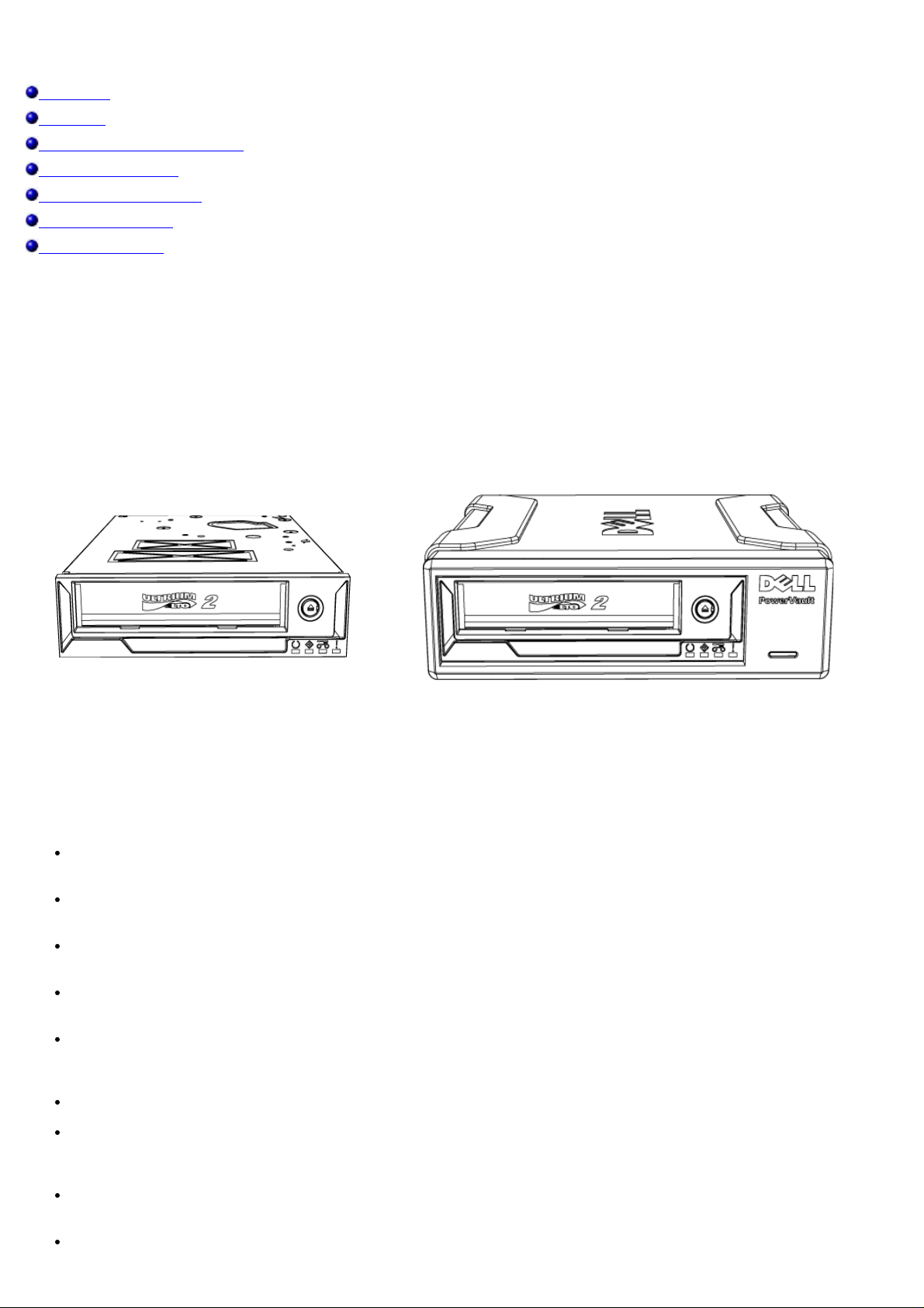
Thie Dell™ PowerVault™ LTO-2-024 is a third generation LTO tape drive designed for high performance, high capacity,
and high reliability data storage in a small form factor. Due to the low power consumption, low heat dissipation, and
multiple mounting holes, the PowerVault LTO-2-024 can easily be integrated into desktop workstations and servers, as
well as in a table-top version connected externally to the server. Using advanced technologies, this drive offers twice the
capacity and data transfer rates of the preceding generation but needs only half the space.
The external table-top version has a rugged design that allows for an easy connection to the host system.
Figure 1: The PowerVault LTO-2-024 Tape Drive
Internal drive External drive
Features
The tape drive has the following features:
Ultra160 SCSI interface
Provides excellent performance.
High speed back-up.
Provides 24 MByte/sec native transfer rate
Backward compatible for investment protection
Read/write compatible with LTO2 and LTO1 media.
Embedded quality monitoring and test features
Provides preventive maintenance information for reduced down time.
Small footprint
5.25 inch half-height form factor with several mounting capabilities for easy and trouble free integration into
servers and workstations.
Rugged external table-top version.
Media Management
Keeps track of Read/Write performance and detects when the drive needs cleaning, if there is a defective or worn
media, or the tape drive head has degraded.
Stand Alone Diagnostics
Provides self-diagnostic routines independent of the host to troubleshoot the drive.
Intelligent Head Cleaning
Page 3

Determines and initiates a head brush cleaning when needed as well as indicating the need for a cleaning cartridge
when required.
Intelligent Thermal Guard
Provides drive and media protection by monitoring the internal temperature. The drive will slow down or even stop
an operation if needed to avoid destruction of critical drive components or the media.
Smart Gripper
Catches and holds the tape pin firmly avoiding "lost leader" problems
Variable Speed
Provides host transfer rate matching by dynamically selecting between five different transfer rates (12 - 24
MB/sec).
TM
Capacity and Transfer Rates
Characteristic Value
Tape length (m) 609
Native capacity (GB) 200
Compressed capacity (GB) assuming 2:1 compression 400
Native transfer rate (MB/sec) 24
Variable speed transfer rates (MB/sec) 12, 15, 18, 21, 24
SCSI Bus Interface
The PowerVault LTO-2-024 tape drive is designed to operate with a burst transfer rate up to 160 MB/sec, and may be
attached to an Ultra160 or Ultra 320 low voltage differential (LVD) SCSI bus.
The tape drive features a high density 68-pin (HD-68) connector for attachment to the server or to the interface
connector in an external tabletop device.
Note: Dell recommends that you attach the tape drive to SCSI controllers that support the SCSI LVD interface only.
Attaching the tape drive to a non-LVD SCSI controller or an 8-bit narrow SCSI controller will degrade the
performance of your tape drive and backup operations. Performance will also be degraded if you attach non-LVD
SCSI devices on the same bus cable as your LVD connection. If you install an adapter, it is recommended that you
purchase a SCSI LVD controller kit that includes the SCSI cable and terminator.
Do not connect the tape drive to a disk RAID controller (disk RAID controllers are not supported). If, however, your
system is a Dell server with an embedded RAID solution that can be configured for RAID/SCSI operation, the tape
drive can be connected to the SCSI channel.
Tape Backup Software
You will need tape backup software that supports the Dell PowerVault™ tape drive. Note that native backup applications
(for example, the UNIX® .tar command) generally do not provide the required data streaming rate to get the full
performance out of your tape drive. (However, if for some reason you need to use the Microsoft® Windows® native
backup software, the drivers for your tape drive under Windows 2003 are included on the CD that came with the drive.)
Dell recommends using a backup application that provides improved memory management as well as other useful
features, such as TapeAlert.
See the User's Operating Guide supplied with your Tape Backup application. For the latest supported software versions, go
to the Dell Support website at www.
support.dell.com or visit the support site of your backup software vendor.
Data Compression
Data Compression is a way to increase capacity on a storage device. Compression ratios are normally specified to be 2:1,
assuming that it is possible to store twice as much data on the tape as without data compression. However, the
compression rate is dependant on the type of data (i.e. ordinary text files can be compressed in a much higher rate than
program, media, and picture files).
There are two ways to compress data, hardware compression and software compression. Hardware compression means
that the data compression is done by the electronics in the storage device. Software compression means that an
Page 4
application program in the host computer is compressing the data before it is sent to the storage device. Hardware
compression is much more efficient and works much faster than software compression.
The PowerVault LTO-2-024 tape drive uses SLDC hardware compression to compress data. This feature is enabled per
default but the user may turn off data compression through the application software.
Note: If the data is compressed by software in the host computer, and then sent to a device that does hardware
compression, the data have a tendency to expand instead of being compressed because the control data used on the
tape.
Be sure to turn the software data compression off if using the PowerVault LTO-2-024 - which has embedded
hardware compression.
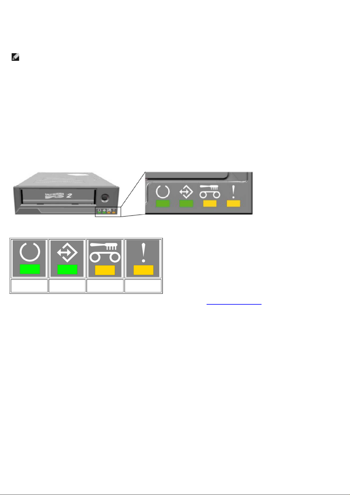
Front Panel LEDs
Figure 2: Status indicators (LEDs) on the front panel
Table 1: Front-Panel LEDs
READY LED
(Green)
Activity LED
(Green)
CLEAN LED
(Amber)
FAULT LED
(Amber)
For complete information including failure conditions and FW loading see Front LED Indicators.
Page 5

Troubleshooting
Hardware
Software
Verifying Recent Changes
Standalone Diagnostics
Media Management Reporting
Problem Situations
In case of problems with the operation of your PowerVault LTO-2-024 tape drive and before contacting the Customer
Services Group, ensure that you check the following:
Hardware Troubleshooting
1. Check that the system recognizes the tape drive during the boot process.
Check that the SCSI host adapter recognizes the tape drive during its initialization.
2.
Check the tape drive front panel LED status.
3.
Check that the SCSI ID of the drive is not conflicting on the SCSI bus.
4.
Check that the power cable is inserted correctly.
5.
Check that the SCSI cable connections including termination are made correctly.
6.
Software Troubleshooting
1. Check that the operating system does not report a problem during the boot.
Check that the driver for the SCSI host adapter is present and loaded properly.
2.
Check that the correct tape device driver has been installed properly - if applicable.
3.
Check that the backup software does not report any error messages when loading.
4.
If any problem occurs, reinstall the backup application software and check that the PowerVault LTO-2-024 is
5.
recognized.
Verifying Recent Changes
If the PowerVault LTO-2-024 has been installed previously and operating correctly but is now incurring a problem, verify
any recent changes to the system to ensure that these changes are not causing the problem. Try the following:
If the system configuration has changed:
1.
Remove the change to see if it affected the tape drive.
If an operating system corrective patch has been installed:
2.
Remove it to see if it affected the tape drive.
If a SCSI device has been added:
3.
Check for SCSI ID conflicts.
If a SCSI device has been added:
4.
Check the SCSI termination.
Standalone Diagnostics
The main objective of Standalone Diagnostics test is to test the complete drive as comprehensively and quickly as possible
without any drive configuration or host support. The tool can also be used to verify tapes.
Starting the Test
Page 6

A Standalone Diagnostic test requires a tape that is not write-protected. The media type can be any media type that
supports a tape format that can be written by the drive.
Notice: Since the test involves write operations, the existing tape contents will be destroyed.
Note: If the Clean LED is On, it will remain On after a test is run. To clear the Clean LED, run a cleaning cartridge.
1. Ensure that no cartridge is loaded. If a cartridge is loaded it can be ejected by double-clicking the eject button.
Enter Service Mode by keeping the Eject button pressed for at least 6 seconds.
2.
The Ready LED (on the left) starts flashing quickly (indicating the drive is in Service Mode and that Service entry
number 1 is active).
Insert the tape cartridge into the drive within 15 seconds.
3.
The drive loads the cartridge and the Ready LED starts flashing indicating that Standalone Diagnostics has started.
The eject button has now returned to normal mode. During the Standalone Diagnostics test, it is possible to abort
the test and eject the cartridge by clicking the eject button. The drive indicates the detection of the abort request
by flashing both the Ready and Activity LEDs. Depending on which stage the test is aborted, it may take a while
before the drive starts the eject operation. When the cartridge has been ejected, all LEDs are turned off. The
Clean LED may still be On.
The Ready LED will continuously flash during the entire testing process. The Activity LED will flash as the tape is in
motion during testing.
If no cartridge has been inserted after 15 seconds, the LEDs revert back to their initial state and the eject button
must be pressed for 6 seconds again to get back to Service Mode.
Test Sequence
The Standalone Diagnostics test will perform the following operations:
Collect Information: Reads and stores drive and media information:
Firmware and drive ID
Tape type and format
Cartridge serial number
Error History Log and Log page 0x33 from EEPROM
Run-time counters from EEPROM
Mainboard Test. Tests the mainboard hardware.
Cartridge Manipulation Test: The Cartridge Manipulation Test performs the same mechanical movement operations as
those performed during Cartridge Load and Eject.
Read/Write Test: This test involves actual reading and writing on the tape medium. A write pass and a read pass are
executed.
When the test has completed without errors the tape cartridge is ejected. No LEDs will be lit. The Clean LED may be On.
Failure Indication
When a failure has been detected the tape is not ejected and the Failure LED will be flashing.
Note for programmers:
Detailed test results are available through the Receive Diagnostics SCSI command. To use this command, Support-only
tools are required.
If a write protected, unsupported, or damaged tape cartridge is inserted prior to starting the Standalone Diagnostics test,
it will be ejected by the drive and the Failure and Activity LEDs will be flashing while the Ready LED is off. The two
flashing LEDs can be turned off by clicking the eject button.
Media Management Reporting
Media Management (MM) is a feature embedded in the PowerVault LTO-2-024 tape drive’s firmware that monitors the
read and write performance of the tape drive and media. Write performance information is written on the media header
every time the media is rewound, and before the media is unloaded.
Page 7

Cleaning is Required
If the write performance falls below a set re-write threshold, the PowerVault LTO-2-024 reports that cleaning is required
by setting the Clean LED to a steady amber. If you are using a backup application that supports TapeAlert then the
application will also report that the drive requires cleaning. See Cleaning Procedure
for instructions on how to clean.
Degraded Media
If the write performance is still below the re-write threshold after cleaning, MM illuminates the Clean LED (set to steady
amber) and reports to the backup application software that the media is degraded.
The degraded media warning means that the cartridge should not be used; it may become worn to the point where drive
cannot write or read successfully using this cartridge.
Problem Situations
Dead on Arrival
1. Check LED activity at power up.
All four LEDs should flash for two seconds at power up and the Ready LED flashes for several seconds while the
power-on self test is running.
Make sure that the power supply used is working:
2.
Measure with an external voltmeter or use a verified supply.
Perform “drive dead test” when supply is verified.
3.
Push the eject button for at least 6 seconds to enter the “drive dead test”. The Activity LED should keep flashing
for approximately 15 seconds.
If the drive still looks dead try to remove all cables except power and rerun the “drive dead test.” A defective cable or
SCSI host bus adapter may affect the drive.
Drive Not Detected by the Operating System
1. Check LED activity at Power Up.
All four LEDs should flash for two seconds at power up and the Ready LED flashes for several seconds while the
power-on self test is running.
Check the SCSI ID.
2.
Each device on the SCSI bus needs a unique SCSI ID. The SCSI ID is set with jumpers on the back of the drive.
See SCSI Configuration
Check SCSI termination.
3.
The SCSI bus should be terminated at the end of the cable. A defective terminator may affect the drive.
.
Will Not Insert/Hold Media or Media is Not Recognized
1. Check the cartridge type.
The PowerVault LTO-2-024 will only accept LTO-3, LTO-2 or LTO-1 type data or cleaning cartridges.
If a wrong type of cartridge is inserted, the drive will eject the media with the Activity LED and Fault LED flashing.
Check media orientation.
2.
The arrow on the cartridge must point into the tape drive facing up when the tape drive is mounted horizontally
with the LEDs on the right.
Media can be inserted only one way and there are mechanical blocks to prevent improper insertion.
Try using a new cartridge.
3.
If it loads correctly, check the failing cartridge for damage.
Check failing media for pin damage (buckling pin).
4.
Hold the cartridge in your hand with the write protect switch to your left and orientation arrow pointing from you.
On the right side, all the way towards the front is a small door that can be opened by sliding the door towards
you. Inside the cartridge you should see a metal pin that is held tightly in place and has media attached to it. If
the pin is missing, loose or damaged the tape will be rejected from the drive.
Page 8

Noisy Tape Drive
There are no fans in the PowerVault LTO-2-024 tape drive and any noise should be very low in idle mode. When the tape
is in motion, noise can come from the media and motors when loading or reading/writing data. The sound should be
steady when streaming but may be intermittent if the host is not delivering data at the data rate of the drive.
Check if the noise comes from the cartridge.
1.
Insert new media – first check this media for any damage.
Check that the PowerVault LTO-2-024 is mounted correctly.
2.
If the PowerVault LTO-2-024 is mounted incorrectly, it can produce abnormal noise when the tape moves.
Cartridge is Stuck Inside the Drive
1. Try to eject the cartridge by pushing the Eject button
Do a drive reset using the Service mode.
2.
Service mode is entered by keeping the eject button pressed for at least six seconds. The Activity LED starts
flashing.
To reset the drive, push the eject button once more to make the Activity LED flash. While
flashing, double-click the eject button. This should invoke a reset of the drive.
If the button is not pushed for 15 seconds, the eject button reverts back to its original cartridge eject function.
3. Power cycle the drive (switch power on/off, if possible).
Fault LED Flashes Amber and the Activity LED is Off
The tape drive reports that it has a failure.
Do a Drive reset using the Service mode.
1.
Service mode is entered by keeping the Eject button pressed for at least six seconds. The Ready LED will start
flashing.
To reset the drive, push the eject button once more to make the Activity LED flash. While this LED is flashing,
double-click the eject button. This should make the drive do a reset.
If the button is not pushed for 15 seconds, the eject button reverts back to its original cartridge eject function.
Power cycle the drive (switch power on/off, if possible).
2.
Fault LED Flashes Amber and the Activity LED is Flashing
The drive signals Media Error.
the Activity LED is
To eject media, press the Eject button.
Ensure the media is the correct type and compatible.
1.
Check the write protection switch position.
2.
Check if the media is damaged (see Will Not Insert/Hold Media or Media is Not Recognized).
3.
Check if an expired cleaning cartridge was used (Clean LED is On).
4.
Clean LED is On
The Clean LED will be lit 100 hours after the last cleaning operation or after an unrecoverable read or write error. These
errors are often caused by debris on the head indicating the drive should be cleaned. See Cleaning Procedure
instruction.
for cleaning
Incorrect Data Compression
1. Check if data is already compressed
Data may have been compressed by software in the host computer.
Page 9

In some cases data will actually expand when subjected to both the hardware and software compression. This can
occur when sending data already compressed at the software application level to the drive and the compression
option is enabled. If this is the case the drive may try to turn compression on and off to optimize the data storage
having the negative unintended result of data expansion.
Note: The PowerVault LTO-2-024 has compression On by default. The compression can be turned Off by
using the SCSI Mode Select command.
2. Turn Off any software compression in use.
The compression is already being accomplished at the hardware level of the PowerVault LTO-2-024 drive.
Therefore any other compression software in the host or on the host bus adapter should be turned off.
The data is compressed using the SLDC (Streaming Lossless Data Compression) algorithm that is based on ALDC
(Adaptive Lossless Data Compression). The SLDC format is defined in the ECMA-321 standard. Two enhancements
are introduced:
o Two methods to reduce expansion of uncompressible data.
o Embedded code word.
Slow Performance
Check that the software driver used for the PowerVault LTO-2-024 is the latest version.
Check the SCSI ID
Each device on the SCSI bus needs a unique SCSI ID. The SCSI ID is set with jumpers on the back of the drive.
Check SCSI termination
The SCSI bus should be terminated at the end of the cable. A defective terminator may affect the drive.
Clean the tape drive.
Perform a Drive Diagnostics test.
Intermittent Failures
If the drive fails intermittently:
Clean the tape drive.
1.
Check the SCSI termination on the SCSI bus.
2.
Check the operating system logs for any errors.
3.
If the problem occurs in the middle of an operation:
Use a different data cartridge.
1.
If the error occurs when the software scans for the files to be backed up, please operate a SCANDISK (or similar)
2.
operation to check the state of the File Systems(s) and hard disk.
If the error consistently occurs on the same file or directory:
Try to remove the file or directory from the backup operation to see if that corrects the problem.
1.
Use a different data cartridge before the drive is sent for service.
2.
If the issue is still not resolved, contact technical support.
3.
Page 10

Installation - Internal drive
Pre-Installed Drives
Installing the Drive
Installing the Drive: SCSI Configuration and Connection
Installing the Drive: Mechanical Installation
Installing Tape Backup Software
Installing Software Device Drivers
Verifying Tape Drive Operation
CAUTION: Before performing any of the procedures in this section, read and follow the safety
instructions located in your tape drive's Product Information Guide.
Pre-Installed Drives
Dell™ installs and configures drives that are shipped as part of the system. However, the tape backup software is not
installed by Dell. Installation instructions are provided with the software.
Store the tape backup software CD/diskette that ships with your system in a safe place in case you ever need to reinstall
the software.
Installing the Drive
If your tape drive is not pre-installed, the installation instructions are in the following sections.
Installing the Drive: Prerequisites
You need the following items to install your internal tape drive:
Ensure that the SCSI host bus adapter is one of the supported types. For a list of the supported SCSI adapters, go
to the Dell Support website at www.
5.25-inch half-height bay.
Internal SCSI-cable with an LVD terminator attached.
Backup application software that supports the internal tape drive.
Phillips screwdriver, if your system uses Phillips screws.
Flat-bladed screwdriver, if your system uses flathead screws.
TORX screwdriver, if your system uses TORX screws.
System documentation, which you can refer to during the installation.
Mounting Bay and Hardware
You need one industry standard, 5 1/4-inch, half-height bay to install the PowerVault LTO-2-024 drive.
CAUTION: The computer must provide forced cooling and be capable of drawing 6 cfm (0.17 cubic
meters/minute or 10.08 cubic meters/hour) of air through the tape drive.
support.dell.com.
See your system documentation to ensure that your system meets these requirements. Also, the documentation specifies
if any special mounting brackets are needed. Next, ensure that all fans in your system are in place and operational and
that empty bays have the appropriate blanking plates so that airflow is maintained.
Installing the Drive: SCSI Configuration and Connection
The PowerVault LTO-2-024 tape drive is designed to operate on an Ultra160 or Ultra320 low voltage differential (LVD)
SCSI bus with an LVD SCSI terminator.
SCSI Configuration
All devices on a SCSI bus need their own unique identification, called the SCSI ID. If a SCSI ID conflict exists, some of the
SCSI devices will not be recognized by your system. Normally the SCSI Host Adaptor (HBA) uses SCSI ID 7 and the
Page 11
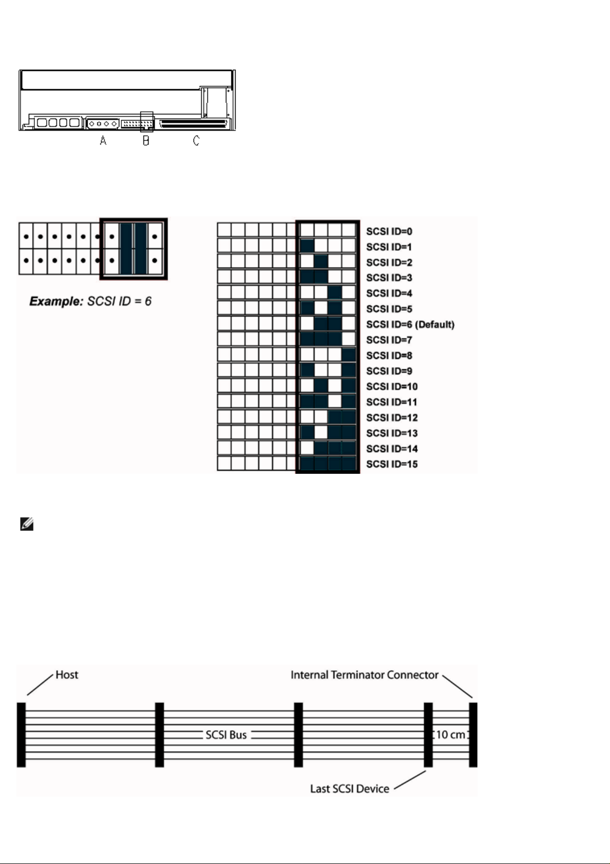
default for the drive is SCSI ID 6. The SCSI ID is set with Jumpers as shown below.
Figure 1: Drive connectors, internal model
termination of the SCSI bus system is a part of the SCSI-cable and not a part of the SCSI-device.
A = Power Connector
B = Service Connector (the right-most 4 strap pin pairs of the complete connector)
C = SCSI connector
Table 1: Service Connector strap settings for SCSI ID (Dark = Strap mounted)
If the tape drive is going to share the SCSI bus with other devices, check the SCSI ID numbers used by the other devices,
then set the drive’s SCSI ID to a number that is not being used.
Note: Notice that the SCSI host adapter uses ID 7.
For optimal performance Dell recommends that the tape drive be the only device on the SCSI bus.
SCSI Termination
A SCSI bus must be terminated at both ends. The SCSI Host Adaptor provides the termination for one end but the tape
drive does not provide termination for the other. Therefore, if the tape drive is the last device on the bus, a cable with
proper LVD termination is required within 10 cm of the drive as illustrated below.
Figure 2: SCSI cable
PowerVault LTO-2-024 has a combined SCSI-LVD/SE interface embedded. The PC-98 Specification specifies that the
Page 12
For internal devices, a SCSI-cable with an integrated terminator or a separate terminator applied to the end connector of
the cable, 10 cm from the last device must be used.
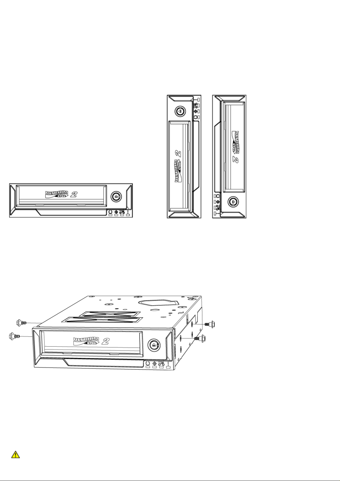
Installing the Drive: Mechanical Installation
Mechanical mounting specifications are specified in the illustration below.
Figure 3: Allowed mounting orientations
Mounting Screw Requirements
The tape drive occupies a half-height 5.25" slot within your system.
Depending on the server design, the tape drive may be supplied with shoulder screws or flat screws, provided in a
separate bag.
Figure 4: Mounting specifications, shoulder screws
The shoulder screws shall be mounted in the four upper mounting holes of the drive. Fix the screws firmly without using
excess force. Slide the drive with the shoulder screws attached into the mounting slot of the server.
If the server is designed for flat screws, it shall be mounted in a carrier sled using mounting brackets:
1. Place drive in carrier and align screw mounting holes in the drive near front of screw hole slots in the carrier (For
best fit, the drive screw holes should be as close to the front of the carrier screw slots as possible.)
2. Using the M3x3mm screws, attach drive to carrier sled through the exposed mounting holes.
Tape Drive Installation
CAUTION: To avoid personal injury or damage to the computer or tape drive, ensure that the system is
Page 13
disconnected from the main power source while you install the drive.
Figure 5: Installing the internal tape drive
1. Gather the necessary tools and materials.
Shut down the system and turn off any connected peripherals.
2.
Remove the side cover, front panel (if necessary), and filler panel from a 5.25-inch bay of your system as detailed
3.
in the system’s documentation.
Orient the drive as shown in figure 6.
4.
Secure the tape drive to the bay.
5.
NOTE:
If shoulder screws are already attached to the drive then slide the drive in the system until it is secure.
If screws are provided in a separate bag install shoulder screws as shown in figure 4.
If the screws provided are flat screws, install the mounting rails as given by the server documentation.
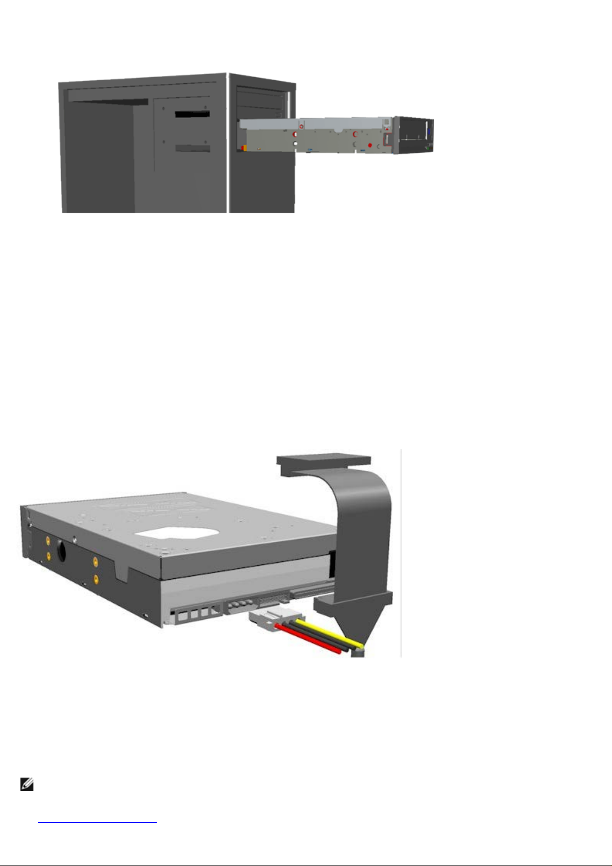
Connect the power and SCSI cable, as shown in figure 6. Be careful to connect the cables in the right orientation.
6.
Before powering on the server, check the SCSI settings as detailed in the next section.
Figure 6: Connecting the cables to the tape drive
Installing Tape Backup Software
Install your backup program as specified in the software’s documentation.
Installing Software Device Drivers
Note: Most backup applications provide all the necessary device driver support for your drive. However, if you intend
to use the drive with the Microsoft® Windows® native backup software you will need the drivers included with the
Dell PowerVault LTO-2-024 Tape Drive Documentation and Drivers CD. The latest drivers can be downloaded from
support.dell.com.
www.
Page 14

Windows Server 2003
Windows Tape Driver Installation
1. Right-click My Computer.
Select Manage, you should see the tape drive under "Other devices" with a "?".
2.
Select the device, right click and select Properties.
3.
Select the appropriate driver location.
4.
Follow the instructions on the screen.
5.
Backup Utility for Windows
The Backup application is included in the Windows Operating System.
Before running the application, make sure the tape driver for your PowerVault LTO-2-024 tape drive is properly installed.
To start the application, click Start Programs Accessories System Tools Backup.
Linux
SCSI Host Adapter
Linux contains a driver for most SCSI host adapters. For more information, see the documentation provided with the SCSI
host adapter.
If the driver cannot be found, see the documentation provided with the SCSI host adapter.
Linux System Command
TAR, CPIO and DD allow simple backup, verify or restore operations to be performed.
Two different device drivers can be used:
A Non Rewind device driver (used to perform append backup)
A Rewind device driver (used only to perform overwrite backup)
Tar command examples:
tar cvf /dev/st0 /etc performs the backup of the /etc directory
tar tvf /dev/st0 reads the data on the tape
tar xvf /dev/st0 restores the data from the tape to the current directory tree
Note: For a complete explanation on how to use the system commands, please refer to the Linux documentation, or
the online help. (MAN command).
Verifying Tape Drive Operation
Once you have installed the PowerVault LTO-2-024 tape drive, verify that it is functioning properly before you attempt to
store data.
Switch on the host computer.
1.
The PowerVault LTO-2-024 tape drive starts a power on self test (POST) that exercises most of its functionality.
2.
All four LEDs light up for 2 seconds during power-up (see Front LED Indicators).
3.
The Activity LED flashes during POST.
4.
When complete only the Ready LED will remain on.
5.
If there is an error, the tape drive will flash the Fault LED. Please refer to Troubleshooting
if this happens.
Page 15

6.
Firmly push the cartridge to its end stop, then release the cartridge.
The Activity LED will start flashing.
The cartridge will move back a short section.
The cartridge will then be lowered into the drive.
The tape will be loaded. The sound of the gears may be heard.
When the tape is fully loaded, the Activity LED will stop blinking, and the Ready LED will remain on.
Page 16

Getting Help
Technical Assistance
Dell Enterprise Training and Certification
Problems With Your Order
Product Information
Returning Items for Warranty Repair or Credit
Before You Call
Technical Assistance
If you need assistance with a technical problem, perform the following steps:
1. Complete the procedures in "Troubleshooting Your System."
2. Run the system diagnostics and record any information provided.
3. Make a copy of the Diagnostics Checklist
4. Use Dell's extensive suite of online services available at Dell Support at www.support.dell.com
installation and troubleshooting procedures.
For more information, see "Online Services."
5. If the preceding steps have not resolved the problem, call Dell for technical assistance.
NOTE: Call technical support from a phone near or at the system so that technical support can assist you with any
necessary procedures.
NOTE: Dell's Express Service Code system may not be available in all countries.
When prompted by Dell's automated telephone system, enter your Express Service Code to route the call directly to
the proper support personnel. If you do not have an Express Service Code, open the Dell Accessories folder,
double-click the Express Service Code icon, and follow the directions.
For instructions on using the technical support service, see "Technical Support Service
NOTE: Some of the following services are not always available in all locations outside the continental U.S. Call your local
Dell representative for information on availability.
, and fill it out.
for help with
" and "Before You Call."
Online Services
You can access Dell Support at support.dell.com. Select your region on the WELCOME TO DELL SUPPORT page, and
fill in the requested details to access help tools and information.
You can contact Dell electronically using the following addresses:
World Wide Web
www.dell.com
www.dell.com/ap (Asian/Pacific countries only)
www.dell.com.cn
www.dell.com/jp
www.euro.dell.com
(China only)
(Japan only)
(Europe only)
Page 17

www.dell.com/la (Latin American countries)
www.dell.ca
Anonymous file transfer protocol (FTP)
ftp.dell.com/
Log in as user:anonymous, and use your e-mail address as your password.
Electronic Support Service
support@us.dell.com
apsupport@dell.com (Asian/Pacific countries only)
cn_support@dell.com (China only)
support.jp.dell.com (Japan only)
support.euro.dell.com(Europe only)
Electronic Quote Service
(Canada only)
sales@dell.com
apmarketing@dell.com (Asian/Pacific countries only)
sales_canada@dell.com (Canada only)
Electronic Information Service
info@dell.com
AutoTech Service
Dell's automated technical support service—AutoTech—provides recorded answers to the questions most frequently asked
by Dell customers about their portable and desktop computer systems.
When you call AutoTech, use your touch-tone telephone to select the subjects that correspond to your questions.
The AutoTech service is available 24 hours a day, 7 days a week. You can also access this service through the technical
support service. See the contact information for your region.
Automated Order-Status Service
To check on the status of any Dell™ products that you have ordered, you can go to www.support.dell.com, or you can
call the automated order-status service. A recording prompts you for the information needed to locate and report on your
order. See the contact information for your region.
Technical Support Service
Page 18

Dell's technical support service is available 24 hours a day, 7 days a week, to answer your questions about Dell hardware.
Our technical support staff use computer-based diagnostics to provide fast, accurate answers.
To contact Dell's technical support service, see "Before You Call
" and then see the contact information for your region.
Dell Enterprise Training and Certification
Dell Enterprise Training and Certification is available; see www.dell.com/training for more information. This service
may not be offered in all locations.
Problems With Your Order
If you have a problem with your order, such as missing parts, wrong parts, or incorrect billing, contact Dell for customer
assistance. Have your invoice or packing slip available when you call. See the contact information for your region.
Product Information
If you need information about additional products available from Dell, or if you would like to place an order, visit the Dell
website at www.dell.com
for your region.
. For the telephone number to call to speak to a sales specialist, see the contact information
Returning Items for Warranty Repair or Credit
Prepare all items being returned, whether for repair or credit, as follows:
1. Call Dell to obtain a Return Material Authorization Number, and write it clearly and prominently on the outside of
the box.
For the telephone number to call, see the contact information for your region.
2. Include a copy of the invoice and a letter describing the reason for the return.
3. Include a copy of any diagnostic information (including the Diagnostics Checklist) indicating the tests you have run
and any error messages reported by the system diagnostics.
4. Include any accessories that belong with the item(s) being returned (such as power cables, media such as CDs and
diskettes, and guides) if the return is for credit.
5. Pack the equipment to be returned in the original (or equivalent) packing materials.
You are responsible for paying shipping expenses. You are also responsible for insuring any product returned, and
you assume the risk of loss during shipment to Dell. Collect-on-delivery (C.O.D.) packages are not accepted.
Returns that are missing any of the preceding requirements will be refused at our receiving dock and returned to you.
Before You Call
NOTE: Have your Express Service Code ready when you call. The code helps Dell's automated-support telephone system
direct your call more efficiently.
Page 19

Remember to fill out the Diagnostics Checklist. If possible, turn on your system before you call Dell for technical
assistance and call from a telephone at or near the computer. You may be asked to type some commands at the
keyboard, relay detailed information during operations, or try other troubleshooting steps possible only at the computer
system itself. Ensure that the system documentation is available.
CAUTION: Before servicing any components inside your computer, see your System Information Guide
for important safety information.
Diagnostics Checklist
Name:
Date:
Address:
Phone number:
Service Tag (bar code on the back of the computer):
Express Service Code:
Return Material Authorization Number (if provided by Dell support technician):
Operating system and version:
Peripherals:
Expansion cards:
Are you connected to a network? Yes No
Network, version, and network card:
Programs and versions:
See your operating system documentation to determine the contents of the system's start-up files. If possible, print
each file. Otherwise, record the contents of each file before calling Dell.
Error message, beep code, or diagnostic code:
Description of problem and troubleshooting procedures you performed:
Back to Contents Page
Page 20

Installation External Drive
Accessories
A
Check that the
Store the tape backup software CD/diskette that came with your system in a safe place in case you ever need to reinstall the software.
Installing the Drive
The installation instructions are in the following sections.
Installing the Drive: Prerequisites
Before installing the external tape drive, ensure that
Drive orientation
The external drive should be mounted in a horizontal position.
Figure
External Tape Drive Installation
Figure
A= ON/OFF Switch
B = Power Connector
C = SCSI Interface and Terminator Connectors
D = SCSI-ID Switch
Installing the Drive: SCSI Configuration and Connection
The
SCSI Configuration
All devices on a SCSI bus need their own unique identification, called the SCSI ID. If a SCSI ID conflict exists, some of the SCSI devices will not be recognized by your system. Normally the SCSI Host Adapter uses SCSI ID 7 and the default for the external drive is SCSI ID 6.
For the external drives, you will find the SCSI-ID setting switch on the rear end of the unit box:
Figure 3.
If the tape drive is going to share the SCSI bus with other devices, check the SCSI ID numbers used by the other devices,
SCSI-bus Termination
For optimal performance, Dell recommends
Figure 4: Termination of external SCSI devices
A = Terminator
B = External SCSI cable
If other external devices are present, the PowerVault LTO-2-024 tape drive can be installed in any position on the SCSI-bus. The PowerVault LTO-2-024 tape drive must be terminated if installed at the end of the SCSI-bus.
Installing Tape Backup Software
To install the tape
Installing
Windows Server 2003
Windows Tape Driver
Backup
The Backup application is included in the Windows Operating System.
Before running the application,
To start
Linux
Linux System Command
TAR
Two different device drivers can be used:
Tar command examples:
tar
tar
tar
Verifying Tape Drive Operation
Once you have installed the PowerVault LTO-2-024 tape drive, verify that it is functioning properly before you attempt to store data.
Installing the Drive
Drive orientation
External Tape Drive Installation
Installing the Drive: SCSI Configuration and Connection
Installing Tape Backup Software
Installing Software Device Drivers
Verifying Tape Drive Operation
CAUTION: Before performing any of the procedures in this section, read and follow the safety instructions located in your tape drive's Product Information Guide.
ccessories
following accessories are delivered with the External drive:
External PowerVault LTO-2-024 tape drive
Power cable
SCSI cable
Terminator
Cleaning cartridge
Documentation and drivers CD
Placemat
Product Information Guide
SCSI Adapter (HBA) (optional)
Tape backup software (optional)
the following items are available:
Ensure that the SCSI host bus adapter is one of the supported types. For a list of the supported SCSI adapters, go to the Dell Support website at www.support.dell.com
External SCSI cable and an LVD terminator
Power cable
Backup application software that supports the tape drive
System documentation
1: Recommended mounting orientation
CAUTION: Do not apply or insert power cord until all connections have been made.
Turn off the power on your server/PC system.
1.
Open your system and install the SCSI controller card in the appropriate slot. When complete, close your system. Connect the tape drive to your Server/PC with the SCSI cable provided to any of the two available SCSI connectors. Remember to place the termination on the free connector on the back of the tape drive.
2.
Connect the power cable provided to the power connector on the tape drive and to the power outlet.
3.
Turn on the power to the tape drive with the ON/OFF switch.
4.
Turn on the power to your server/PC and check that all your SCSI devices are recognized by the SCSI controller board.
5.
2 Drive connectors, external tabletop model
PowerVault LTO-2-024 tape drive is designed to operate on an Ultra160 and Ultra320 low voltage differential (LVD) SCSI bus with an LVD SCSI terminator.
SCSI-ID Thumb-wheel
Note: The SCSI host adapter normally uses ID 7.
Note: Make certain the terminator is connected to the second SCSI connector.
backup software, see the documentation that ships with the software.
Software Device Drivers
Note: Most backup applications provide all the necessary device driver support for your drive. However, if you intend to use the drive with the Microsoft® Windows® native backup software you will need the drivers included with the Dell PowerVault LTO-2-024 Documentation and Drivers CD. For the latest drivers go to the Dell Support website at www.support.dell.com.
Installation
1. Right-click My Computer.
Select Manage, you should see the tape drive under "Other devices" with a "?".
2.
Select the device, right click and select Properties.
3.
Select the appropriate driver location.
4.
Follow the instructions on the screen.
5.
Utility for Windows
ensure that the tape driver for your PowerVault LTO-2-024 tape drive is properly installed.
the application, click Start Programs Accessories System Tools Backup.
, CPIO and DD allow simple Backup, Verify or Restore operations to be performed.
A Non Rewind device driver (used to perform append backup)
A Rewind device driver (used only to perform overwrite backup)
cvf /dev/st0 /etc performs the backup of the /etc directory
tvf /dev/st0 reads the data on the tape
xvf /dev/st0 restores the data from the tape to the current directory tree
Note: For any questions related to this operating system or its embedded backup applet, see the documentation provided on the Linux CD- ROM.
1. Switch on the external PowerVault LTO-2-024 (The LEDs may be flickering until the host computer is switched on)
Switch on the host computer.
2.
The PowerVault LTO-2-024 tape drive starts a power on self test (POST) that exercises most of its functionality.
3.
All four LEDs light up for 2 seconds during power-up (see Front LED Indicators).
4.
The Activity LED flashes during POST.
5.
All LED's will turn off except for the Ready LED.
6.
If there was an error, the tape drive will flash the Fault LED. Please refer to Troubleshooting if this happens.
Firmly push the cartridge in until the loading mechanism is activated, then release the cartridge.
7.
· The Activity LED will start flashing.
· The cartridge will move back a short section.
· The cartridge will then be lowered into the drive.
· The tape will be loaded. The sound of the gears may be heard.
· When the tape is fully loaded, the Activity LED will stop blinking, and the Ready LED will be on.
then set the drive’s SCSI ID to a number that is not being used.
— External Tape Drives
that the PowerVault LTO-2-024 is the only device on the external SCSI-bus. In that case it must be terminated using the external SCSI termination installed in the second SCSI connector position.
Page 21

Contacting Dell
To contact Dell electronically, you can access the following websites:
www.dell.com
www.support.dell.com (support)
For specific web addresses for your country, find the appropriate country section in the table below.
NOTE: Toll-free numbers are for use within the country for which they are listed.
NOTE: In certain countries, support specific to Dell™ XPS™ computers is available at a separate telephone
number listed for participating countries. If you do not see a telephone number listed that is specific for XPS
computers, you may contact Dell through the support number listed and your call will be routed
appropriately.
When you need to contact Dell, use the electronic addresses, telephone numbers, and codes provided in the
following table. If you need assistance in determining which codes to use, contact a local or an international
operator.
NOTE: The contact information provided was deemed correct at the time that this document went to print
and is subject to change.
Country (City)
International Access
Code Country Code
City Code
Anguilla General Support toll-free: 800-335-0031
Antigua and
Barbuda
Argentina (Buenos
Aires)
International Access
Code: 00
Country Code: 54
General Support 1-800-805-5924
Website: dell.com.ar
E-mail: us_latin_services@dell.com
E-mail for desktop and portable computers:
la-techsupport@dell.com
E-mail for servers and EMC® storage products:
la_enterprise@dell.com
Customer Care toll-free: 0-800-444-0730
Department Name or Service Area,
Website and E-Mail Address
Local Numbers, and
Toll-Free Numbers
Area Codes,
City Code: 11
Aruba General Support toll-free: 800-1578
Australia (Sydney)
International Access
Code: 0011
Technical Support toll-free: 0-800-444-0733
Technical Support Services toll-free: 0-800-444-0724
Sales 0-810-444-3355
Website: support.ap.dell.com
E-mail: support.ap.dell.com/contactus
Page 22

Country Code: 61
City Code: 2
General Support 13DELL-133355
Austria (Vienna)
Website: support.euro.dell.com
E-mail: tech_support_central_europe@dell.com
Home/Small Business Sales 0820 240 530 00
Home/Small Business Fax 0820 240 530 49
International Access
Code: 900
Country Code: 43
City Code: 1
Bahamas General Support toll-free: 1-866-278-6818
Barbados General Support 1-800-534-3066
Belgium (Brussels)
International Access
Code: 00
Country Code: 32
City Code: 2
Home/Small Business Customer Care 0820 240 530 14
Preferred Accounts/Corporate Customer Care 0820 240 530 16
Support for XPS 0820 240 530 81
Home/Small Business Support for all other Dell
computers
Preferred Accounts/Corporate Support 0660 8779
Switchboard 0820 240 530 00
Website: support.euro.dell.com
Tech Support for XPS 02 481 92 96
Tech Support for all other Dell computers 02 481 92 88
Tech Support Fax 02 481 92 95
Customer Care 02 713 15 65
Corporate Sales 02 481 91 00
0820 240 530 17
Bermuda General Support 1-800-342-0671
Bolivia General Support toll-free: 800-10-0238
Brazil
International Access
Code: 00
Country Code: 55
City Code: 51
British Virgin
Islands
Brunei
Country Code: 673
Fax 02 481 92 99
Switchboard 02 481 91 00
Website: dell.com/br
Customer Support, Tech Support
0800 90 3355
Technical Support Fax 51 481 5470
Customer Care Fax 51 481 5480
Sales 0800 90 3390
General Support toll-free: 1-866-278-6820
Technical Support (Penang, Malaysia) 604 633 4966
Customer Care (Penang, Malaysia) 604 633 4888
Transaction Sales (Penang, Malaysia) 604 633 4955
Online Order Status: dell.ca/ostatus
Page 23

AutoTech (automated Hardware and Warranty
Support)
Customer Service (Home Sales/Small Business) toll-free: 1-800-847-4096
Customer Service (med./large business, government) toll-free: 1-800-326-9463
toll-free: 1-800-247-9362
Customer Service (printers, projectors, televisions,
Canada (North York,
Ontario)
International Access
Code: 011
Cayman Islands General Support 1-800-805-7541
Chile (Santiago)
Country Code: 56
City Code: 2
handhelds, digital jukebox, and wireless)
Hardware Warranty Support (Home Sales/Small
Business)
Hardware Warranty Support (med./large bus.,
government)
Hardware Warranty Support (printers, projectors,
televisions, handhelds, digital jukebox, and wireless)
Sales (Home Sales/Small Business) toll-free: 1-800-387-5752
Sales (med./large bus., government) toll-free: 1-800-387-5755
Spare Parts Sales & Extended Service Sales 1 866 440 3355
Sales and Customer Support toll-free: 1230-020-4823
toll-free: 1-800-847-4096
toll-free: 1-800-906-3355
toll-free: 1-800-387-5757
1-877-335-5767
China (Xiamen)
Country Code: 86
City Code: 592
Technical Support website: support.dell.com.cn
Technical Support E-mail: cn_support@dell.com
Customer Care E-mail: customer_cn@dell.com
Technical Support Fax 592 818 1350
Technical Support (Dell™ Dimension™ and Inspiron) toll-free: 800 858 2968
Technical Support (OptiPlex™, Latitude™, and Dell
Precision™)
Technical Support (servers and storage) toll-free: 800 858 0960
Technical Support (projectors, PDAs, switches,
routers, and so on)
Technical Support (printers) toll-free: 800 858 2311
Customer Care toll-free: 800 858 2060
Customer Care Fax 592 818 1308
Home and Small Business toll-free: 800 858 2222
Preferred Accounts Division toll-free: 800 858 2557
toll-free: 800 858 0950
toll-free: 800 858 2920
Large Corporate Accounts GCP toll-free: 800 858 2055
Large Corporate Accounts Key Accounts toll-free: 800 858 2628
Large Corporate Accounts North toll-free: 800 858 2999
Large Corporate Accounts North Government and
Education
toll-free: 800 858 2955
Page 24

Large Corporate Accounts East toll-free: 800 858 2020
Large Corporate Accounts East Government and
Education
Large Corporate Accounts Queue Team toll-free: 800 858 2572
Large Corporate Accounts South toll-free: 800 858 2355
Large Corporate Accounts West toll-free: 800 858 2811
Large Corporate Accounts Spare Parts toll-free: 800 858 2621
Colombia General Support 980-9-15-3978
Costa Rica General Support 0800-012-0435
toll-free: 800 858 2669
Czech Republic
(Prague)
International Access
Code: 00
Country Code: 420
Denmark
(Copenhagen)
International Access
Code: 00
Country Code: 45
Website: support.euro.dell.com
E-mail: czech_dell@dell.com
Technical Support 22537 2727
Customer Care 22537 2707
Fax 22537 2714
Technical Fax 22537 2728
Switchboard 22537 2711
Website: support.euro.dell.com
Technical Support for XPS 7010 0074
Technical Support for all other Dell computers 7023 0182
Customer Care (Relational) 7023 0184
Home/Small Business Customer Care 3287 5505
Switchboard (Relational) 3287 1200
Switchboard Fax (Relational) 3287 1201
Switchboard (Home/Small Business) 3287 5000
Switchboard Fax (Home/Small Business) 3287 5001
Dominica General Support toll-free: 1-866-278-6821
Dominican Republic General Support 1-800-148-0530
Ecuador General Support toll-free: 999-119
El Salvador General Support 01-899-753-0777
Website: support.euro.dell.com
E-mail: fi_support@dell.com
Finland (Helsinki)
International Access
Code: 990
Country Code: 358
City Code: 9
Technical Support 0207 533 555
Customer Care 0207 533 538
Switchboard 0207 533 533
Sales under 500 employees 0207 533 540
Fax 0207 533 530
Sales over 500 employees 0207 533 533
Page 25

Fax 0207 533 530
Website: support.euro.dell.com
Home and Small Business
Technical Support for XPS 0825 387 129
Technical Support for all other Dell computers 0825 387 270
Customer Care 0825 823 833
France (Paris)
(Montpellier)
International Access
Code: 00
Country Code: 33
City Codes: (1) (4)
Germany (Langen)
International Access
Code: 00
Country Code: 49
City Code: 6103
Switchboard 0825 004 700
Switchboard (calls from outside of France) 04 99 75 40 00
Sales 0825 004 700
Fax 0825 004 701
Fax (calls from outside of France) 04 99 75 40 01
Corporate
Technical Support 0825 004 719
Customer Care 0825 338 339
Switchboard 01 55 94 71 00
Sales 01 55 94 71 00
Fax 01 55 94 71 01
Website: support.euro.dell.com
E-mail: tech_support_central_europe@dell.com
Technical Support for XPS 069 9792 7222
Technical Support for all other Dell computers 069 9792-7200
Home/Small Business Customer Care 0180-5-224400
Global Segment Customer Care 06103 766-9570
Preferred Accounts Customer Care 06103 766-9420
Large Accounts Customer Care 06103 766-9560
Public Accounts Customer Care 06103 766-9555
Switchboard 06103 766-7000
Website: support.euro.dell.com
Greece
International Access
Code: 00
Country Code: 30
Grenada General Support toll-free: 1-866-540-3355
Guatemala General Support 1-800-999-0136
Guyana General Support toll-free: 1-877-270-4609
Technical Support 00800-44 14 95 18
Gold Service Technical Support 00800-44 14 00 83
Switchboard 2108129810
Gold Service Switchboard 2108129811
Sales 2108129800
Fax 2108129812
Page 26

Website: support.ap.dell.com
Technical Support E-mail: HK_support@Dell.com
Technical Support (Dimension and Inspiron) 2969 3188
Hong Kong
International Access
Code: 001
Country Code: 852
India
Technical Support (OptiPlex, Latitude, and Dell
Precision)
Technical Support (PowerApp™, PowerEdge™,
PowerConnect™, and PowerVault™)
Customer Care 3416 0910
Large Corporate Accounts 3416 0907
Global Customer Programs 3416 0908
Medium Business Division 3416 0912
Home and Small Business Division 2969 3105
E-mail: india_support_desktop@dell.com
india_support_notebook@dell.com
india_support_Server@dell.com
Technical Support
and 1600448046
Sales (Large Corporate Accounts) 1600 33 8044
Sales (Home and Small Business) 1600 33 8046
2969 3191
2969 3196
1600338045
Ireland
(Cherrywood)
International Access
Code: 00
Country Code: 353
City Code: 1
Website: support.euro.dell.com
E-mail: dell_direct_support@dell.com
Sales
Ireland Sales 01 204 4444
Dell Outlet 1850 200 778
Online Ordering HelpDesk 1850 200 778
Customer Care
Home User Customer Care 01 204 4014
Small Business Customer Care 01 204 4014
Corporate Customer Care 1850 200 982
Technical Support
Technical Support for XPS 1850 200 722
Technical Support for all other Dell computers 1850 543 543
At-Home-Service — Technical Support Queries 1850 200 889
General
Fax/Sales Fax 01 204 0103
Switchboard 01 204 4444
U.K. Technical Support (dial within U.K. only) 0870 353 0800
U.K. Customer Care (dial within U.K. only) 0870 353 0202
Page 27

Corporate Customer Care (dial within U.K. only) 0870 353 0240
U.K. Sales (dial within U.K. only) 0870 353 4000
Korea (Seoul)
Website: support.euro.dell.com
Home and Small Business
Technical Support 02 577 826 90
Italy (Milan)
International Access
Code: 00
Country Code: 39
City Code: 02
Jamaica General Support (dial from within Jamaica only) 1-800-682-3639
Customer Care 02 696 821 14
Fax 02 696 821 13
Switchboard 02 696 821 12
Corporate
Technical Support 02 577 826 90
Customer Care 02 577 825 55
Fax 02 575 035 30
Switchboard 02 577 821
Website: support.jp.dell.com
Technical Support (servers) toll-free: 0120-198-498
Technical Support outside of Japan (servers) 81-44-556-4162
Technical Support (Dimension and Inspiron) toll-free: 0120-198-226
Technical Support outside of Japan (Dimension and
Inspiron)
81-44-520-1435
Japan (Kawasaki)
International Access
Code: 001
Country Code: 81
City Code: 44
Technical Support (Dell Precision, OptiPlex, and
Latitude)
Technical Support outside of Japan (Dell Precision,
OptiPlex, and Latitude)
Technical Support (PDAs, projectors, printers, routers) toll-free: 0120-981-690
Technical Support outside of Japan (PDAs, projectors,
printers, routers)
Faxbox Service 044-556-3490
24-Hour Automated Order Status Service 044-556-3801
Customer Care 044-556-4240
Business Sales Division (up to 400 employees) 044-556-1465
Preferred Accounts Division Sales (over 400
employees)
Public Sales (government agencies, educational
institutions, and medical institutions)
Global Segment Japan 044-556-3469
toll-free:0120-198-433
81-44-556-3894
81-44-556-3468
044-556-3433
044-556-5963
Individual User 044-556-1760
Switchboard 044-556-4300
E-mail: krsupport@dell.com
Page 28

International Access
Support toll-free: 080-200-3800
Country Code: 52
Code: 001
Support (Dimension, PDA, Electronics and
Accessories)
toll-free: 080-200-3801
Country Code: 82
City Code: 2
Latin America
Luxembourg
International Access
Code: 00
Sales toll-free: 080-200-3600
Fax 2194-6202
Switchboard 2194-6000
Customer Technical Support (Austin, Texas, U.S.A.) 512 728-4093
Customer Service (Austin, Texas, U.S.A.) 512 728-3619
Fax (Technical Support and Customer Service)
(Austin, Texas, U.S.A.)
Sales (Austin, Texas, U.S.A.) 512 728-4397
SalesFax (Austin, Texas, U.S.A.)
Website: support.euro.dell.com
Support 342 08 08 075
Home/Small Business Sales +32 (0)2 713 15 96
Corporate Sales 26 25 77 81
512 728-3883
512 728-4600
or 512 728-3772
Country Code: 352
Macao
Country Code: 853
Malaysia (Penang)
International Access
Code: 00
Country Code: 60
City Code: 4
Customer Care +32 (0)2 481 91 19
Fax 26 25 77 82
Technical Support toll-free: 0800 105
Customer Service (Xiamen, China) 34 160 910
Transaction Sales (Xiamen, China) 29 693 115
Website: support.ap.dell.com
Technical Support (Dell Precision, OptiPlex, and
Latitude)
Technical Support (Dimension, Inspiron, and
Electronics and Accessories)
Technical Support (PowerApp, PowerEdge,
PowerConnect, and PowerVault)
Customer Care
Transaction Sales toll-free: 1 800 888 202
Corporate Sales toll-free: 1 800 888 213
toll-free: 1 800 880 193
toll-free: 1 800 881 306
toll-free: 1800 881 386
toll-free: 1800 881 306
(option 6)
Mexico
International Access
Code: 00
001-877-384-8979
Customer Technical Support
or 001-877-269-3383
50-81-8800
Sales
or 01-800-888-3355
001-877-384-8979
Customer Service
Page 29

or 001-877-269-3383
50-81-8800
Main
Montserrat General Support toll-free: 1-866-278-6822
Netherlands Antilles General Support 001-800-882-1519
or 01-800-888-3355
Netherlands
(Amsterdam)
International Access
Code: 00
Country Code: 31
City Code: 20
New Zealand
International Access
Code: 00
Country Code: 64
Website: support.euro.dell.com
Technical Support for XPS 020 674 45 94
Technical Support for all other Dell computers 020 674 45 00
Technical Support Fax 020 674 47 66
Home/Small Business Customer Care 020 674 42 00
Relational Customer Care 020 674 4325
Home/Small Business Sales 020 674 55 00
Relational Sales 020 674 50 00
Home/Small Business Sales Fax 020 674 47 75
Relational Sales Fax 020 674 47 50
Switchboard 020 674 50 00
Switchboard Fax 020 674 47 50
Website: support.ap.dell.com
E-mail: support.ap.dell.com/contactus
General Support 0800 441 567
Nicaragua General Support 001-800-220-1006
Website: support.euro.dell.com
Norway (Lysaker)
International Access
Code: 00
Country Code: 47
Panama General Support 001-800-507-0962
Peru General Support 0800-50-669
Poland (Warsaw)
International Access
Code: 011
Country Code: 48
Technical Support for XPS 815 35 043
Technical Support for all other Dell products 671 16882
Relational Customer Care 671 17575
Home/Small Business Customer Care 23162298
Switchboard 671 16800
Fax Switchboard 671 16865
Website: support.euro.dell.com
E-mail: pl_support_tech@dell.com
Customer Service Phone 57 95 700
Customer Care 57 95 999
Sales 57 95 999
Customer Service Fax 57 95 806
Page 30

City Code: 22
Reception Desk Fax 57 95 998
09/091
Portugal
International Access
Code: 00
Country Code: 351
Puerto Rico General Support 1-800-805-7545
St. Kitts and Nevis General Support toll-free: 1-877-441-4731
St. Lucia General Support 1-800-882-1521
St. Vincent and the
Grenadines
Switchboard 57 95 999
Website: support.euro.dell.com
Technical Support 707200149
Customer Care 800 300 413
Sales
Fax 21 424 01 12
General Support toll-free: 1-877-270-4609
NOTE: The phone numbers in this section should be
called from within Singapore or Malaysia only.
800 300 410 or 800 300 411 or
800 300 412 or 21 422 07 10
Singapore
(Singapore)
International Access
Code: 005
Country Code: 65
Slovakia (Prague)
International Access
Code: 00
Country Code: 421
Website: support.euro.dell.com
Technical Support (Dimension, Inspiron, and
Electronics and Accessories)
Technical Support (OptiPlex, Latitude, and Dell
Precision)
Technical Support (PowerApp, PowerEdge,
PowerConnect, and PowerVault)
Customer Care
Transaction Sales toll-free: 1 800 394 7412
Corporate Sales toll-free: 1 800 394 7419
Website: support.euro.dell.com
E-mail: czech_dell@dell.com
Technical Support 02 5441 5727
Customer Care 420 22537 2707
Fax 02 5441 8328
Tech Fax 02 5441 8328
toll-free: 1 800 394 7430
toll-free: 1 800 394 7488
toll-free: 1 800 394 7478
toll-free: 1 800 394 7430
(option 6)
South Africa
(Johannesburg)
International Access
Code:
Switchboard (Sales) 02 5441 7585
Website: support.euro.dell.com
E-mail: dell_za_support@dell.com
Gold Queue 011 709 7713
Technical Support 011 709 7710
Customer Care 011 709 7707
Page 31

Country Code: 27
Technical Support (OptiPlex, Latitude, Inspiron,
City Code: 11
Sales 011 709 7700
Fax 011 706 0495
Switchboard 011 709 7700
Southeast Asian and
Pacific Countries
Spain (Madrid)
International Access
Code: 00
Country Code: 34
City Code: 91
Technical Support, Customer Service, and Sales
(Penang, Malaysia)
Website: support.euro.dell.com
Home and Small Business
Technical Support 902 100 130
Customer Care 902 118 540
Sales 902 118 541
Switchboard 902 118 541
Fax 902 118 539
Corporate
Technical Support 902 100 130
Customer Care 902 115 236
Switchboard 91 722 92 00
Fax 91 722 95 83
Website: support.euro.dell.com
604 633 4810
Sweden (Upplands
Vasby)
International Access
Code: 00
Country Code: 46
City Code: 8
Switzerland (Geneva)
International Access
Code: 00
Country Code: 41
City Code: 22
Technical Support for XPS 0771 340 340
Technical Support for all other Dell products 08 590 05 199
Relational Customer Care 08 590 05 642
Home/Small Business Customer Care 08 587 70 527
Employee Purchase Program (EPP) Support 020 140 14 44
Technical Support Fax 08 590 05 594
Sales 08 590 05 185
Website: support.euro.dell.com
E-mail: Tech_support_central_Europe@dell.com
Technical Support for XPS 0848 33 88 57
Technical Support (Home and Small Business) for all
other Dell products
Technical Support (Corporate) 0844 822 844
Customer Care (Home and Small Business) 0848 802 202
Customer Care (Corporate) 0848 821 721
0844 811 411
Taiwan
Fax 022 799 01 90
Switchboard 022 799 01 01
Website: support.ap.dell.com
E-mail: ap_support@dell.com
Page 32

International Access
toll-free: 00801 86 1011
Code: 002
Country Code: 886
Dimension, and Electronics and Accessories)
Technical Support (PowerApp, PowerEdge,
PowerConnect, and PowerVault)
Customer Care
Transaction Sales toll-free: 00801 65 1228
Corporate Sales toll-free: 00801 651 227
toll-free: 00801 60 1256
toll-free: 00801 60 1250
(option 5)
Website: support.ap.dell.com
Technical Support (OptiPlex, Latitude, and Dell
Thailand
International Access
Code: 001
Country Code: 66
Trinidad/Tobago General Support 1-800-805-8035
Turks and Caicos
Islands
Precision)
Technical Support (PowerApp, PowerEdge,
PowerConnect, and PowerVault)
Customer Care
Corporate Sales toll-free: 1800 006 009
Transaction Sales toll-free: 1800 006 006
General Support toll-free: 1-866-540-3355
Website: support.euro.dell.com
E-mail: dell_direct_support@dell.com
Customer Care website:
support.euro.dell.com/uk/en/ECare/form/home.asp
toll-free: 1800 0060 07
toll-free: 1800 0600 09
toll-free: 1800 006 007
(option 7)
U.K. (Bracknell)
International Access
Code: 00
Country Code: 44
City Code: 1344
Sales
Home and Small Business Sales 0870 907 4000
Corporate/Public Sector Sales 01344 860 456
Customer Care
Home and Small Business Customer Care 0870 906 0010
Corporate Customer Care 01344 373 185
Preferred Accounts (500–5000 employees) Customer
Care
Global Accounts Customer Care 01344 373 186
Central Government Customer Care 01344 373 193
Local Government & Education Customer Care 01344 373 199
Health Customer Care 01344 373 194
Technical Support
Technical Support for XPS 0870 366 4180
Technical Support (Corporate/Preferred
Accounts/PAD [1000+ employees])
0870 906 0010
0870 908 0500
General
Page 33

Technical Support for all other products 0870 908 0800
Home and Small Business Fax 0870 907 4006
Uruguay General Support toll-free: 000-413-598-2521
Automated Order-Status Service toll-free: 1-800-433-9014
AutoTech (portable and desktop computers) toll-free: 1-800-247-9362
U.S.A. (Austin,
Texas)
International Access
Code: 011
Country Code: 1
Hardware and Warranty Support (Dell TV, Printers,
and Projectors) for Relationship customers
Americas Consumer XPS Support toll-free: 1-800-232-8544
Consumer (Home and Home Office) Support for all
other Dell products
Customer Service toll-free: 1-800-624-9897
Employee Purchase Program (EPP) Customers toll-free: 1-800-695-8133
Financial Services website:
www.dellfinancialservices.com
Financial Services (lease/loans) toll-free: 1-877-577-3355
Financial Services (Dell Preferred Accounts [DPA]) toll-free: 1-800-283-2210
Business
Customer Service and Support toll-free: 1-800-456-3355
Employee Purchase Program (EPP) Customers toll-free: 1-800-695-8133
Support for printers, projectors, PDAs, and MP3
players
toll-free: 1-877-459-7298
toll-free: 1-800-624-9896
toll-free: 1-877-459-7298
Public (government, education, and healthcare)
Customer Service and Support toll-free: 1-800-456-3355
Employee Purchase Program (EPP) Customers toll-free: 1-800-695-8133
toll-free: 1-800-289-3355
Dell Sales
or toll-free: 1-800-879-3355
Dell Outlet Store (Dell refurbished computers) toll-free: 1-888-798-7561
Software and Peripherals Sales toll-free: 1-800-671-3355
Spare Parts Sales toll-free: 1-800-357-3355
Extended Service and Warranty Sales toll-free: 1-800-247-4618
Fax toll-free: 1-800-727-8320
Dell Services for the Deaf, Hard-of-Hearing, or
Speech-Impaired
U.S. Virgin Islands General Support 1-877-673-3355
Venezuela General Support 8001-3605
toll-free: 1-877-DELLTTY
(1-877-335-5889)
Back to Contents Page
Page 34

Page 35

Specifications
Tape Drive Capacity and Performance
Media Specifications and Compatibility
Mechanical Specifications
Power Specifications
Environmental Specifications
Tape Drive Capacity and Performance
Drive Model Tape Format
PowerVault LTO-2-024
*) Capacity and transfer rate given in native/compressed (assuming 2:1 compression)
Ultrium Gen. 2
Ultrium Gen. 1
Capacity
200/400 GB
100/200 GB
*)
Sustained Transfer Rate
24/48 MB/sec
16/32 MB/sec
*)
Interface Type
Ultra160
Ultra160
Media Specifications and Compatibility
Drive Model Media Name Tape Length
PowerVault LTO-2-024
LTO Ultrium Generation 2 (Read/Write compatible) 609 m 200 GB/ 400 GB
LTO Ultrium Generation 1 (Read/Write compatible) 609 m 100 GB/ 200 GB
(Native/compressed)
Mechanical Specifications
Standard drive mounting, internal drive:
Fits in 5.25-inch half-height standard drive bay. Standard mounting holes for a half-height drive.
Height/width/depth Weight
Internal drive: 41.3/146.0/214 mm (1.63/5.75/8.43 inch) 1.4 kg (3.2 lbs)
External drive: 65/205/259 mm (2.56/8.1/10.2 inch) 3.0 kg (6.6 lbs)
Capacity
Power Specifications
Internal drive:
External drive: AC input, 50-60 Hz: 100 VAC / 0.6 A or 240 VAC / 0.3 A
Operating: 18 W
Sleep mode with cartridge inserted: 9 W
Environmental Specifications
0
Operating +10 to +40 20 to 80
Storage -30 to +60 5 to 90
Transport -40 to +60 5 to 95
Temperature (
Rel. Humidity (%)
C)
Page 36

Glossary
Active
Termination
ALDC Adaptive Lossless Data Compression. A hardware data compression method.
ASPI
Auto
sensing
EEPROM
GUI Graphical User Interface. Software which interacts with the user.
ID See SCSI ID.
LVD
RWW
SCSI
SCSI ID
SLDC™
HBA Host Board Adapter. The SCSI interface board located in the server/PC
Enhanced SCSI termination that provides better stability and noise immunity of the electrical signals on the
SCSI bus lines.
Advanced SCSI Programming Interface. Standard SCSI software that acts as a liaison between host
adapters and SCSI device drivers. ASPI enables host adapters and device drivers to share a single SCSI
hardware interface.
PowerVault LTO-2-024 feature that allows detection of the best transfer rate to use for optimizing
performance on the SCSI bus.
Electrically Erasable Programmable Read Only Memory. An integrated circuit typically used to store
configuration information.
Low Voltage Differential. A SCSI interface that provides better stability and noise immunity of the electrical
signals on the SCSI bus. LVD also allows longer SCSI bus length and improved data rates.
Read While Write. All Tandberg tape drives automatically and internally read the data just being written to
the tape to avoid writing to bad block.
Small Computer Signaling Interface. The PowerVault LTO-2-024 utilizes the SCSI Ultra160 interface which
allows for a transfer rate of up to 160 MB/sec on the bus.
A unique identifier assigned to SCSI devices that enables them to communicate with a computer when they
are attached to a host adapter via the SCSI bus. Each SCSI host adapter board has eight available SCSI
IDs with numbers 0 through 7 (or 0 through 15 for Wide SCSI adapters). Usually the host adapter itself is
assigned SCSI ID 7.
Streaming Lossless Data Compression. The hardware data compression method specified as the standard
for the two Ultrum tape formats and thus used with the PowerVault LTO-2-024 tape drives.
Page 37

Operation
Front LED Indicators
Tape Cartridge Operation
Handling and Storing LTO Cartridges
Cleaning the Tape Drive
Front LED Indicators
Figure 1: Status indicators (LEDs)
Table 1: Front LED behaviour during normal operation
Drive State
Normal operation
LED-test.
The LEDs are turned ON briefly.
Power-On Self-Test in progress Flashing OFF OFF OFF
Cartridge not loaded ON OFF OFF OFF
Cartridge not loaded,
Drive needs cleaning
Cartridge loaded, no activity ON OFF OFF OFF
Cartridge loaded, no activity
Drive needs cleaning
Cartridge loaded, activity ON Flashing OFF OFF
Cartridge loaded, activity
Drive needs cleaning
1)
READY LED
(Green)
ON ON ON ON
ON OFF ON OFF
ON OFF ON OFF
ON Flashing ON OFF
ACTIVITY LED
(Green)
CLEAN LED
(Amber)
2)
FAULT LED
(Amber)
Cleaning cartridge loaded, Activity OFF Flashing ON OFF
Cartridge loading or unloading ON Flashing OFF OFF
Cartridge loading or unloading
Drive needs cleaning
1)
LED's are turned on during boot process briefly, then the Ready and Activity LEDs operate till the POST is complete.
2)
A solid amber Clean LED indicates that the drive needs cleaning. In most cases it will continue to operate normally if
cleaned within a short time.
ON Flashing ON OFF
Page 38

Table 2: Front LED behaviour during firmware update operations
Drive State
FW updates
3)
Firmware download
Firmware download
in progress
3)
in progress,
drive needs cleaning
4)
Frimware update
Firmware update
in progress
4)
in progress,
drive needs cleaning
3)
Firmware download refers to the transfer of firmware from the host to the drive
4)
Firmware update refers to the drive incorporating the new firmware (storing in flash memeory)
READY LED
(Green)
ACTIVITY LED
(Green)
Flashing OFF OFF OFF
Flashing OFF ON OFF
Flashing Flashing OFF OFF
Flashing Flashing ON OFF
CLEAN
LED
(Amber)
FAULT LED
(Amber)
Table 3: Front LED behavior during error conditions
Drive State
Error conditions
Cleaning cartridge loaded,
Cleaning failed
READY LED
(Green)
ACTIVITY LED
(Green)
OFF OFF ON OFF
CLEAN
LED
(Amber)
FAULT LED
(Amber)
Unrecoverable failure OFF OFF OFF Flashing
Unrecoverable failure
Drive needs cleaning
OFF OFF ON Flashing
Firmware download or update failure Flashing Flashing OFF Flashing
Firmware download or update failure
drive needs cleaning
Maximum operating temperature
exceeded
5)
Maximum operating temperature
exceeded, drive needs cleaning
Media Error (wrong or harmed
media)
Flashing Flashing ON Flashing
ON OFF OFF ON
ON OFF ON ON
5)
ON Flashing OFF Flashing
Media Error (wrong or harmed
media)
ON Flashing ON Flashing
Drive needs cleaning
5)
The fault LED must be solid ON to indicate an over temperature condition. If a tape is loaded, it will be ejected. This
LED will remain on until the drive temperature drops below a secondary temprature limit.
CAUTION: During firmware update, the power to the drive must not be switched off.
Switching it off will cause the drive to become inoperative.
Ready LED
The Ready LED indicates that the drive is connected to the power supply. It may be turned off during an error condition.
However, at least one LED will be lit when the drive is connected to power.
Page 39

Activity LED
When the Activity LED is ON and the Fault LED is off, the drive is performing an operation. The Eject button should not be
pressed as the operation will be aborted, unless the application has disabled the Eject function during operation. If
aborted during a write operation, the written data may be incorrectly terminated resulting in errors if an attempt is made
to restore the data.
Clean LED
When the Clean LED is steady on, the drive is indicating that it needs cleaning by a cleaning cartridge. The Clean LED will
be turned on by:
100 hours of tape operation since last cleaning.
Media Management determined a suspect cleaning condition.
A fault situation where cleaning should be done to recover.
When the Clean LED is on, a cleaning cartridge should be run before any other tape activity is attempted.
Once lit, the Clean LED can only be turned off by running a cleaning cartridge. A power cycle will not clear the Clean LED.
Fault LED
If the Fault LED is lit, see Troubleshooting.
Tape Cartridge Operation
Use only certified quality cartridges for the PowerVault LTO-2-024 tape drives. Do not use worn or audibly noisy
cartridges. Cartridges which frequently require rewriting of large numbers of data-blocks per track should also be
discarded.
Loading a Data Cartridge
The cartridge must be inserted with the label facing up and the tape dust cover towards the LEDs as shown below. The
drive has a semi-soft loading mechanism: Slide the cartridge slowly into the drive until it stops firmly, then let go. The
cartridge will then move back a very short distance. The drive, once it has detected the cartridge, will lock the cartridge
and move it down into the drive mechanism. The tape threading will then take place and the motor sound may be heard.
Once a cartridge is detected by the Drive, the Activity LED will start flashing, and continue flashing until the tape is fully
threaded into the drive. With a brand-new tape, the drive will initialize the tape, spending some extra time until the
Activity LED is turned off.
To prevent damage to the drive or the cartridge:
DO NOT use excessive force
Ensure that you insert the cartridge in the correct orientation
Do not drop the drive or the cartridge (handle with care)
Figure 2: Cartridge insertion
Ejecting a Data Cartridge
The cartridge can be ejected either by pressing the Eject button located on the drive’s front panel, or by an Unload SCSI
command. The drive automatically rewinds and ejects the cartridge.
Notice: For the integrity of your backups and restores, do not press the Eject button when the Activity LED is
flashing.
Page 40

Note: Some backup applications issue a command to the drive that prevents the Eject button from ejecting the
tape. If the tape does not eject, try using the commands in your backup software.
Figure 3: Location of the eject button
Write Protecting the Cartridge
The LTO cartridge can be write-protected by moving the tab as indicated in the figure below.
Figure 4: LTO cartridge write protect switch
A = Tape Window. The window is spring loaded and closed when the cartridge is not inserted.
B = Write Protect Switch. The picture shows the switch in the non-protected position. When it is write protected, the
switch is to the right and the area is red.
Handling and Storing LTO Cartridges
To improve data reliability and cartridge lifetime, it is important to handle and store the cartridges properly.
Do not drop the cartridges.
Ensure that the cartridges are stored in a clean environment away from dirt, dust, or moisture.
It is recommended to store cartridges in their protective case.
Do not expose the cartridge to direct sunlight or excessive heat sources.
Do not touch the tape media inside a cartridge.
Prior to use, the LTO cartridge should be adapted to the operating environment for a time at least equal to the
period it has been out of the operating environment outside and above 10ºC – 35ºC (up to a maximum of 24
hours). Recommended operating temperature is 25ºC or below (see tape drive specifications).
Replace worn or excessively noisy LTO cartridges.
Store the LTO cartridge in a cool and dry environment. Avoid high temperatures. Recommended maximum
temperature is 25ºC/77ºF and 50 % RH humidity.
Do not store the LTO cartridge near devices such as computer monitors, TV sets, or loudspeakers with strong
magnetic fields (not exceeding 4000/A/m).
Cleaning the Tape Drive
A standard LTO type cleaning cartridge is included with your tape drive. Before use, the cleaning cartridge should be
Page 41

conditioned to the operating environment for a time at least equal to the period it has been outside the operating
environment and outside or above 10ºC – 35ºC (up to a maximum of 24 hours). Recommended operating temperature is
25ºC/77ºF or below (see tape drive specifications).
Recommended Cleaning Interval
If the Clean LED is On, a head cleaning is recommended (the drive is still fully operational with this LED steady On). The
LED is triggered after 100 hours of tape use, if the Media Management Algorithm has detected severely degraded write
performance, or if a hard read/write error has occurred. The LED is not turned off by a power cycle and is only reset when
cleaning has completed successfully.
Cleaning Procedure
Figure 5: Activity and Clean LEDs
A= Activity LED
B= Clean LED
1. Load the cleaning cartridge into the PowerVault LTO-2-024 tape drive.
2. The cleaning process will begin automatically. This is indicated by the front LEDs on the product as seen in
figure 5.
3. The Clean LED will be OFF if the cleaning was successful ((up to 3 minutes).
4. The cartridge may be ejected by pushing the Eject button, when cleaning is complete.
Note: The cleaning cartridge can only be used 50 times. If an expired cleaning cartridge is inserted the Clean LED
will remain on and the cleaning cartridge will not be ejected. Press the Eject button to eject the cleaning cartridge.
Page 42

Dell™ PowerVault™ 110T DLT VS 80 Drive
Initial release: 1 October 2001
Last Revised: 18 November 2005
 Loading...