

Dell PowerVault 775N User Manual [en, de, es, fr]

Dell™ Systems
Rack Installation Guide
D4fLL
www.dell.com | support.dell.com

Notes, Notices, and Cautions
^ NOTE: A NOTE indicates important information that heips you make better use of your computer.
O NOTICE: A NOTICE indicates either potentiai damage to hardware or ioss of data and teiis you
how to avoid the probiem.
/K CAUTION: A CAUTION indicates a potential for property damage, personal injury,
or death.
Information in this document is subject to change without notice.
© 2002 Dell Computer Corporation. All rights reserved.
Reproduction in any manner whatsoever without the written permission of Dell Computer Corporation is strictly
forbidden.
Trademarks used in this text: Dell, the DELL logo, VersaRails, and RapidRails are trademarks of Dell Computer
Corporation.
Other trademarks and trade names may be used in this document to refer to either the entities claiming the marks and
names or their products. Dell Computer Corporation disclaims any proprietary interest in trademarks and trade names
other than its own.
February 2002 P/N 5G382 Rev. AOO

Contents
Safety Instructions.........................................................................1-1
Installation Instructions............................................................... 1-2
Four-Post Rack Installation
Before You Begin
Installation Tasks.............................................................................1-4
Recommended Tools and Supplies
RapidRails Rack Kit Contents.......................................................1-4
VersaRails Rack Kit Contents.......................................................1-5
Removing the Rack Doors.............................................................1-6
Marking the Rack.............................................................................1-6
Installing the RapidRails Slide Assemblies
Installing the VersaRails Slide Assemblies
Installing the System in the Rack
Installing the Cable-Management Arm......................................1-14
Routing Cables..............................................................................1-16
Replacing the Rack Doors...........................................................1-17
............................................................................
Two-Post Rack Installation
Two-Post Rack Installation Tasks..............................................1-18
Recommended Tools and Supplies...........................................1-19
Rack Kit Contents......................................................................... 1-19
Marking the Rack
Installing the Slide Assemblies in the Rack..............................1-22
Installing the System in the Rack
Installing the Cable-Management Arm
Routing Cables.............................................................................. 1-27
..........................................................................
........................................................
.............................................
...............................
.............................
..............................................
.......................................................
..............................................
.....................................
1-3
1-3
1-4
1-8
1-10
1-12
1-18
1-20
1-27
1-27
Index
Contents I 3

Figures
Figure 1-1. RapidRails Rack Kit Contents
Figure 1-2. VersaRails Rack Kit Contents
Figure 1-3. One Rack Unit
Figure 1-4. Marking the Vertical Rails
Figure 1-5. Installing the RapidRails Slide Assemblies
Figure 1-6. Installing the VersaRails Slide Assemblies
Figure 1-7. Installing the System in the Rack
(RapidRails or VersaRails)
Figure 1-8. Installing the Cable-Management Arm
Figure 1-9. Installing the Cable-Management Arm
Figure 1-10. Routing the Power Cords
Figure 1-11. Routing Cables ..................................................... 1-17
Figure 1-12. Two-Post Rack Kit Components
Figure 1-13. Two-Post, Open-Frame Relay Rack
Universal-Hole Spacing
Figure 1-14. Two-Post, Open-Frame Relay Rack
Wide-Hole Spacing.............................................. 1-21
Figure 1-15. Installing the Slide Assemblies for
Center-Mount Configuration
Figure 1-16. Rotating the Front Mounting Bracket for
Flush-Mount Installation
Figure 1-17. Installing the Slide Assemblies for
Flush-Mount Configuration ............................... 1-26
.........................................................
..............................
..............................
.....................................
........
.......
................................
..............
..............
....................................
........................
.....................................
..............................
....................................
1-5
1-6
1-7
1-8
1-9
1-11
1-13
1-14
1-15
1-16
1-19
1-20
1-23
1-25
+ I Contents

Safety Instructions
Use the following safety guidelines to ensure your own personal safety and to help proteet
your server, storage system, or applianee from potential damage. For eomplete safety and
regulatory information, refer to your System Information doeument. Warranty information
might be ineluded within this doeument or as a separate doeument.
/t\ CAUTION: Precautions for Rack-Mountable Products
Observe the following preeautions for raek stability and safety. Also refer to the raek
installation doeumentation aeeompanying the system and the raek for speeifie warning
and/or eaution statements and proeedures.
Servers, storage systems, and applianees are eonsidered to be eomponents in a raek. Thus,
"eomponent" refers to any server, storage system, or applianee, as well as to various
peripherals or supporting hardware.
/t\ CAUTION: Installing system components in a rack without the front and side
stabilizers installed could cause the rack to tip over, potentially resulting in
bodily injury under certain circumstances. Therefore, always install the
stabilizers before installing components in the rack.
After installing system/components in a rack, never pull more than one
component out of the rack on its slide assemblies at one time. The weight of
more than one extended component could cause the rack to tip over and injure
someone.
^ NOTE: Your system is safety-certified as a free-standing unit and as a component for
use in a rack cabinet using the customer rack kit when both the rack cabinet and rack
kit were designed for your system. The instaiiation of your system and rack kit in any
other rack cabinet has not been approved by any safety agencies. It is your
responsibiiity to have the finai combination of system and rack kit in a cabinet
evaiuated for suitabiiity by a certified safety agency. The manufacturer disciaims aii
warranties and iiabiiity in connection with such combinations.
• System raek kits are intended to be installed in an approved raek by trained serviee
teehnieians. If you install the kit in any other raek, be sure that the raek meets the
speeifieations.
CAUTION: Do not move large racks by yourself. Due to the height and weight of
A
the rack, it is recommended that a minimum of two people perform this task.
Before working on the raek, make sure that the stabilizers are seeured to the raek,
extend to the floor, and that the full weight of the raek rests on the floor. Install front
and side stabilizers on a single raek or front stabilizers for joined multiple raeks before
working on the raek.
Rack Instaiiation Guide
I 1-1

• Always load the rack from the bottom up, and load the heaviest item in the rack first.
• Make sure that the rack is level and stable before extending a component from the
rack.
• Use caution when pressing the component rail release latches and sliding a component
into or out of a rack* the slide rails can pinch your fingers.
• After a component is inserted into the rack, carefully extend the rail into a locking
position, and then slide the component into the rack.
• Do not overload the power supply branch circuit that provides power to the rack.
The total rack load should not exceed 80 percent of the branch circuit rating.
• Ensure that proper airflow is provided to components in the rack.
• Do not step on or stand on any system/component when servicing other
systems/components in a rack.
Installation Instructions
This installation guide provides instructions for trained service technicians installing one or
more systems in an open-frame relay rack or in a rack cabinet. The RapidRails™ rack kit can
be installed in all the manufacturer’s rack cabinets without tools, and the VersaRails™ rack
kit can be installed in most industry-standard rack cabinets. The procedures for installing
both RapidRails and VersaRails rack kits are similar. One rack kit is required for each system
to be installed in the rack cabinet.
This guide includes procedures for the following rack kits:
• RapidRails kit in a four-post rack cabinet
• VersaRails kit in a four-post rack cabinet
• Two-post kit (installed in either center-mount or flush-mount configuration, for 7- or
6-inch-wide racks)
For ease in troubleshooting and the identification of system health, these rack kits include a
status-indicator cable that extends the information on the two-color status indicators on
the front and back panels to the back of the cable-management arm. For more information
on these indicators, your system User’s Guide.
Before attempting this installation, you should read through this entire document carefully.
/l\ CAUTION: Do not install rack kit components designed for another system. Use
only the rack kit for your system. Using the rack kit for another system may
result in damage to the system and personal injury to yourself and to others.
1-2 I Rack Installation Guide

Rack Requirements for VersaRails
О NOTICE: The VersaRails rack kit is intended to be installed by trained service
technicians in a rack that meets the specifications of American National
Standards Institute (ANSD/Electronic Industries Association (EIA) standard
ANSI/EIA-310-D-92, International Electrotechnical Commission (lEC) 297, and
Deutsche Industrie Norm (DIN) 41494. One rack kit is required for each system that
is installed in a rack.
Four-Post Rack Installation
Before attempting this installation, you should read through this entire proeedure earefully.
Before You Begin
Before you begin installing your system in the raek, earefully read "Safety Instruetions,"
found earlier in this guide, as well as the safety instruetions found in your system’s System
Information doeument for additional information.
!\ CAUTION: When installing multiple systems in a rack, complete all of the
A
procedures for the current system before attempting to install the next system.
/t\ CAUTION: Rack cabinets can be extremely heavy and move easily on the casters.
The cabinet has no brakes. Use extreme caution while moving the rack cabinet.
Retract the leveling feet when relocating the rack cabinet. Avoid long or steep
inclines or ramps where loss of cabinet control may occur. Extend the leveling
feet for support and to prevent the cabinet from rolling.
Important Safety Information
Observe the safety preeautions in the following subseetions when installing your system in
the raek.
/t\ CAUTION: You must strictly follow the procedures in this document to protect
yourself as well as others who may be involved. Your system may be very large
and heavy, and proper preparation and planning are important to prevent injury
to yourself and to others. This becomes increasingly important when systems are
installed high up in the rack.
Rack Stabilizer Feet
CAUTION: Installing systems in a rack without the front and side stabilizer feet
installed could cause the rack to tip over, potentially resulting in bodily injury
under certain circumstances. Therefore, always install the stabilizer feet before
installing components in the rack.
Rack Installation Guide | 1-3

/К CAUTION: After installing systems in a rack, never pull more than one system
out of the rack on its slide assemblies at one time. The weight of more than one
extended system could cause the rack to tip over and cause injury.
The stabilizer feet help prevent the гаек from tipping over when a system or other
eomponent is pulled out of the raek with the slide assemblies fully extended. Refer to the
doeumentation provided with the raek eabinet for instruetions on installing and anehoring
the stabilizer feet.
Installation Tasks
Installing a raek kit involves performing the following tasks in their numbered order:
Removing the raek doors
Marking the raek
Installing the slide assemblies in the raek:
• RapidRails installation
• VersaRails installation
Installing the system in the raek
Installing the eable-management arm
Routing eables
Replaeing the raek doors
Recommended Tools and Supplies
You may need the following tools and supplies to install the system in a four-post raek:
• A #2 Phillips serewdriver (for installing VersaRails slide assemblies)
• Masking tape or a felt-tip pen, for use in marking the mounting holes to be used
RapidRails Rack Kit Contents
The RapidRails raek kit ineludes the following items (see Figure 1-1):
• One pair of RapidRails slide assemblies
• One eable-management arm
• One status indieator eable
• Tie-wraps
1-4 I Rack Installation Guide
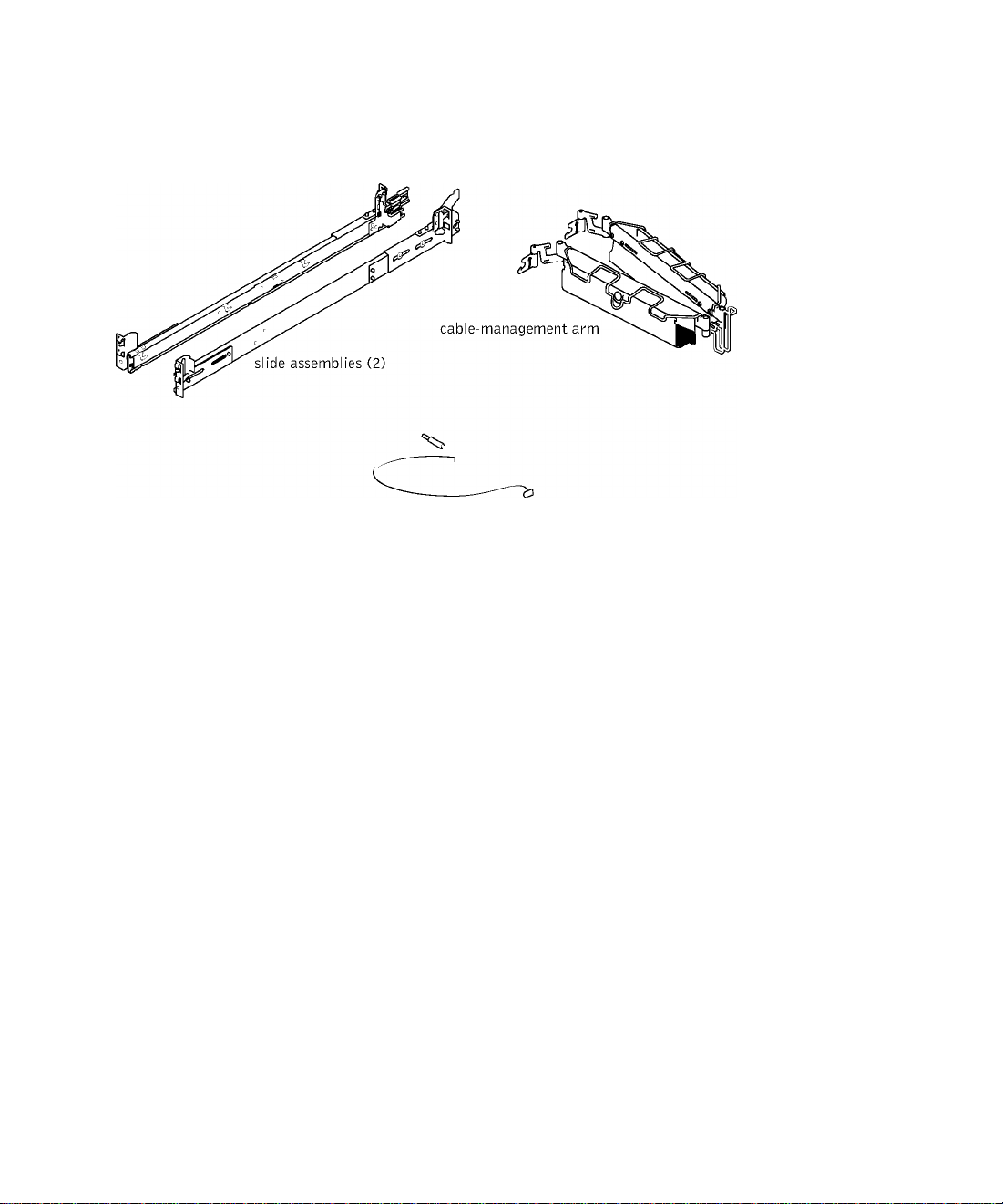
Figure 1-1. RapidRails Rack Kit Contents
status indicator cabie
VersaRails Rack Kit Contents
The VersaRails raek kit ineludes the following items (see Figure 1-2):
• One pair of VersaRails slide assemblies
• One eable-management arm
• One status indieator eable
• Eight 10-32 X 0.5-ineh flange-head Phillips serews
• Tie-wraps
^ NOTE: The nonmetric screws described in iiiustrations and in procedurai steps are
identified by size and number of threads per inch. For exampie, a #10 Phiiiips-head
screw with 32 threads per inch is identified as a 10-32 screw.
Rack Instaiiation Guide | 1-5
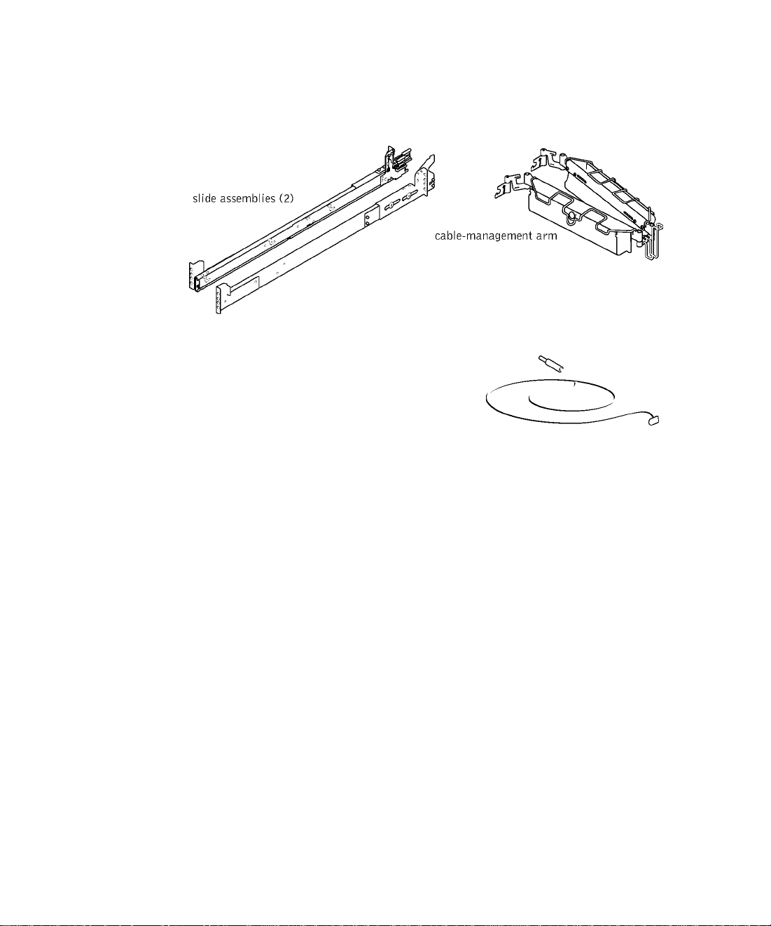
Figure 1-2. VersaRails Rack Kit Contents
10-32 X 0.5-inch
flange-head
Phillips screw (8)
T
status indicator cable
Removing the Rack Doors
See the proeedures for removing doors in the doeumentation provided with your гаек
eabinet.
CAUTION: Because of the size and weight of the rack cabinet doors, never attempt to remove or install them by yourself.
CAUTION: Store the two doors where they will not injure someone if the doors accidently fall over.
Marking the Rack
You must allow 2 U (88 mm, or 3.5 inehes) of vertieal spaee for eaeh system you install in
the raek. Raek eabinets that meet EIA-310 standards have an alternating pattern of three
holes per raek unit with eenter-to-eenter hole spaeing (beginning at the top hole of a 1-U
spaee) of 15.9 mm, 15.9 mm, and 12.7 mm (0.625 ineh, 0.625 ineh, and 0.5 ineh) for the
front and baek vertieal rails (see
1-6 I Rack Installation Guide
Figure 1-3). Raek eabinets may have round or square holes.

^ NOTE: The vertical rails may be marked by horizontal lines and numbers in 1-U
increments. If you wish, you can make a note of the number marking on the rack's
vertical rail. It is not necessary to mark or place tape on the rack. If you choose this
method, skip ahead to the procedure "Installing the RapidRails Slide Assemblies."
Figure 1-3. One Rack Unit
□
12.7 mm (0.5 inch)
□
15.4 mm (0.625 inch)
1 U (44 mm or 1.75 inches)
□
15.4 mm (0.625 inch)
□
12.7 mm (0.5 inch)
□
/t\ CAUTION: If you are installing more than one system, install the slide assemblies
so that the first system is installed in the lowest available position in the rack.
To mark the rack, perform the following steps:
1 Place a mark on the rack’s front vertical rails where you want to locate the bottom of
the system you are installing in the rack cabinet.
The bottom of each 1-U space is at the middle of the narrowest metal area between
holes (marked with a horizontal line on some rack cabinets—see Figure 1-4).
2 Place a mark 88 mm (5.5 inches) above the original mark you made (or count up six
holes in a rack that meets EIA-510 standards) and mark the rack’s front vertical rails
with a felt-tipped pen or masking tape (if you counted holes, place a mark just above
the top hole). This mark or piece of tape indicates where the system’s upper edge will
be located on the vertical rails (see Figure 1-4).
Rack Installation Guide | 1-7
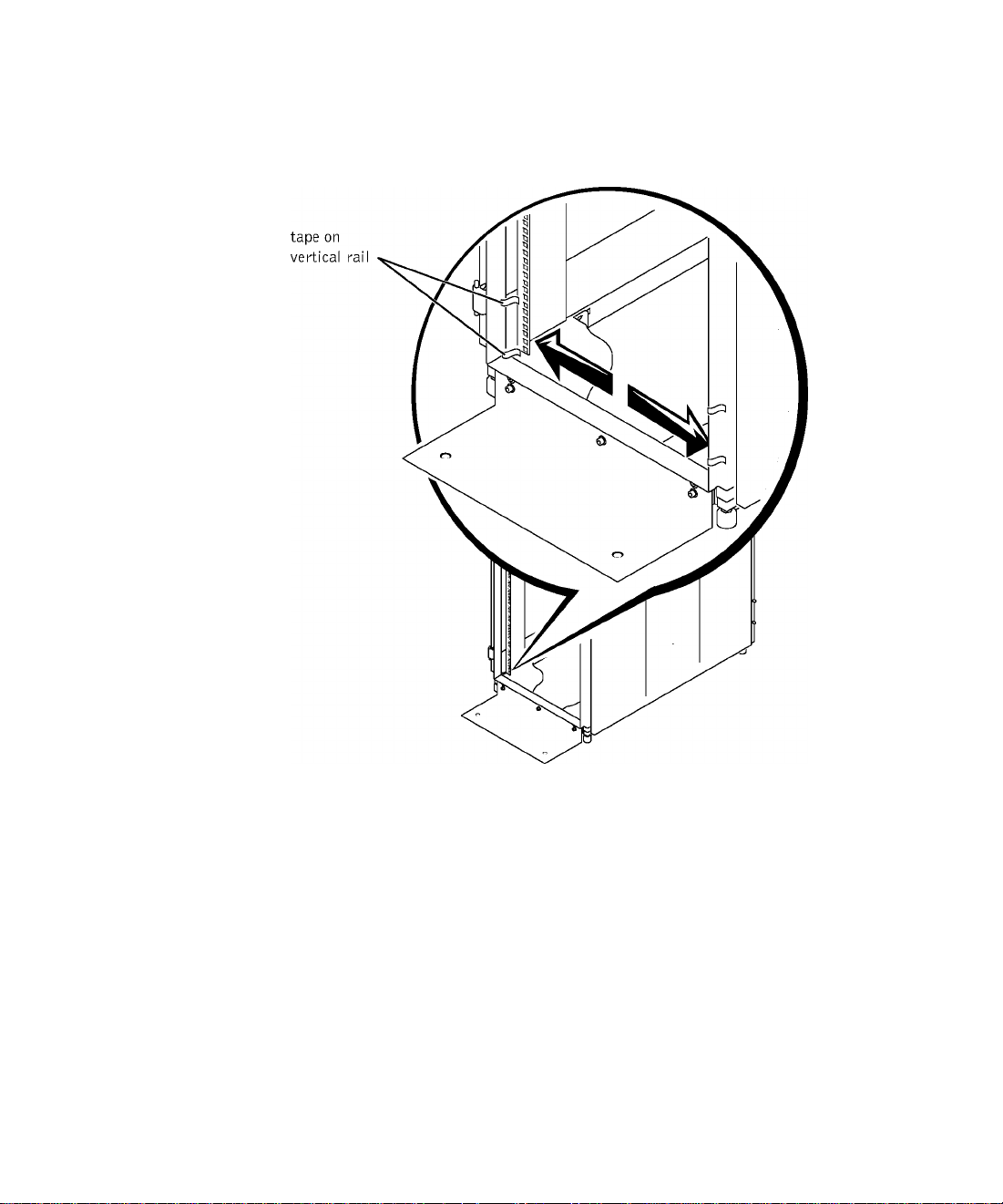
Figure 1-4. Marking the Vertical Rails
Installing the RapidRails Slide Assemblies
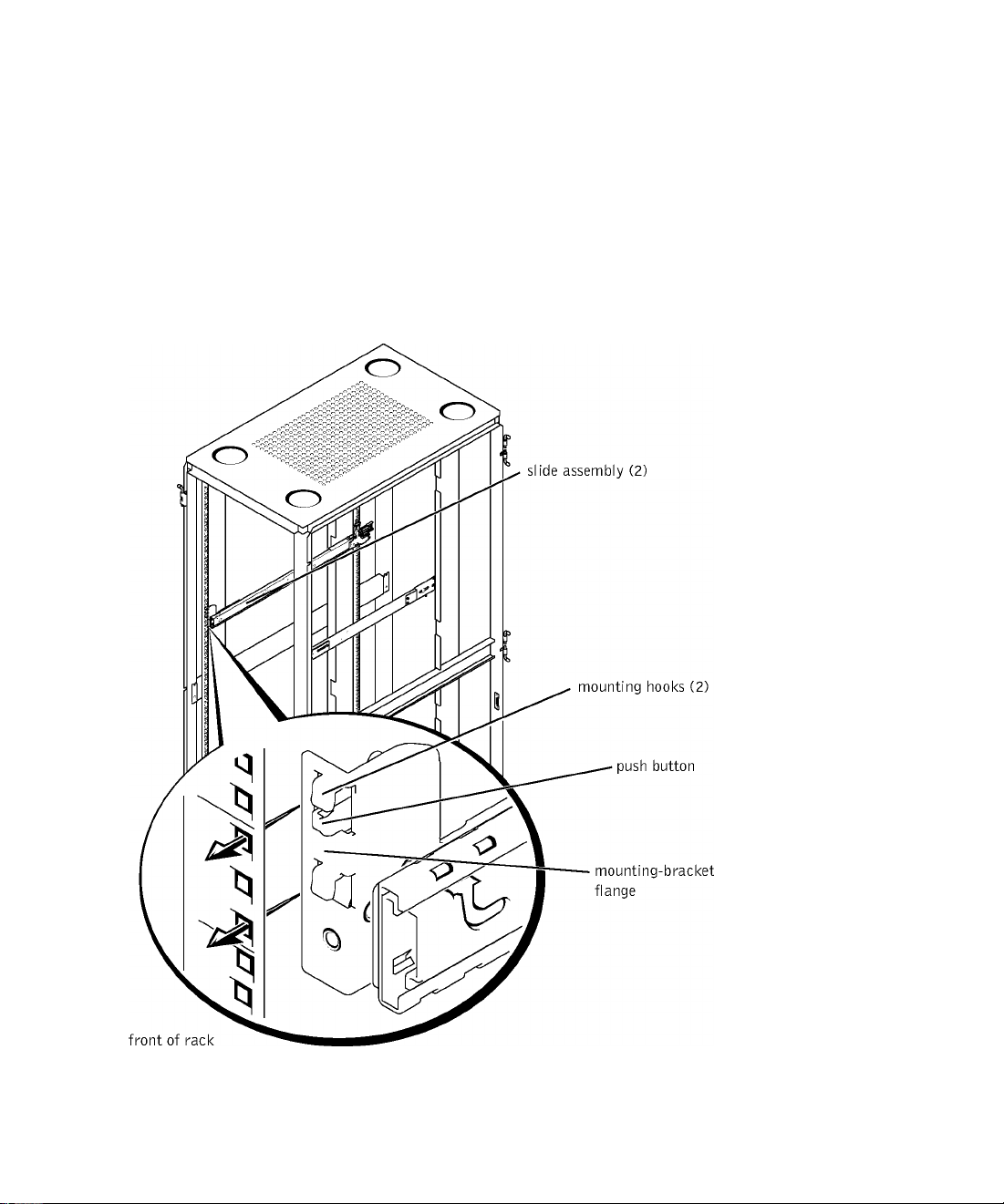
1 At the front of the гаек eabinet, position one of the RapidRails slide assemblies so that
its mounting-braeket flange fits between the marks or tape you plaeed on the raek (see
Figure 1-5).
The top mounting hook on the slide assembly’s front mounting braeket flange should
enter the top hole between the marks you made on the vertieal rails.
2 Push the slide assembly forward until the top mounting hook enters the top square
hole that you plaeed a mark just above on the vertieal rail, and then push down on the
mounting-braeket flange until the mounting hooks seat in the square holes and the
push button pops out and elieks (see Figure 1-5).
1-8 I Rack Installation Guide
3 At the back of the cabinet, pull back on the mounting-bracket flange until the top
mounting hook is in the top square hole, and then push down on the flange until the
mounting hooks seat in the square holes and the push button pops out and clicks.
+ Repeat steps 1 through 7 for the slide assembly on the other side of the rack.
5 Ensure that the rails are mounted at the same vertical position on both sides of the
rack.
Figure 1-5. Installing the RapidRails Slide Assemblies
Rack Installation Guide | 1-9

Installing the VersaRails Slide Assemblies
1 At the front of the гаек eabinet, position one of the VersaRails slide assemblies so that
its mounting-braeket flange fits between the marks or tape (or numbered loeation) on
the raek (see Figure 1-6).
The four holes on the front of the mounting braeket should align with four of the
holes between the marks you made on the front vertieal rail.
2 Install two 10-32 x 0.5-ineh flange-head Phillips serews in the mounting flange’s top
hole and the third-from-top hole to seeure the slide assembly to the front vertieal rail
(see Figure 1-6).
3 At the baek of the eabinet, pull baek on the mounting-braeket flange until the
mounting holes align with their respeetive holes on the baek vertieal rail.
+ Install two 10-32 x 0.5-ineh flange-head Phillips serews in the baek mounting flange’s
top and third-from-top holes to seeure the slide assembly to the baek vertieal rail.
5 Repeat steps 1 through C for the slide assembly on the other side of the raek.
6 Ensure that the slide assemblies are mounted at the same position on the vertieal rails
on eaeh side of the raek.
1-10 I Rack Installation Guide
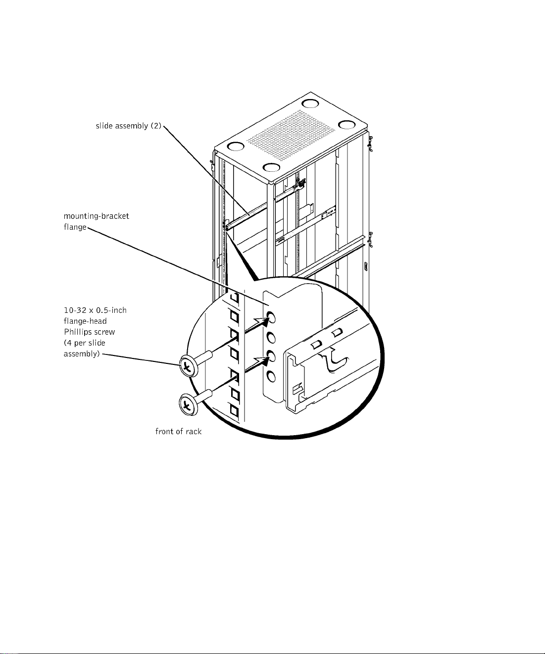
Figure 1-6. Installing the VersaRails Slide Assemblies
Rack Installation Guide | 1-11

Installing the System in the Rack
/t\ CAUTION: If you are installing more than one system, install the first system in
the lowest available position in the rack.
CAUTION: Never pull more than one component out of the rack at a time.
1 Pull the two slide assemblies out of the гаек until they loek in the fully extended
position.
/t\ CAUTION: Because of the size and weight of the system, never attempt to install
the system in the slide assemblies by yourself.
2 Lift the system into position in front of the extended slides.
3 Plaee one hand on the front-bottom of the system and the other hand on the baek-
bottom of the system.
+ Tilt the baek of the system down while aligning the baek shoulder serews on the sides
of the system with the baek slots on the slide assemblies.
5 Engage the baek shoulder serews into their slots.
6 Lower the front of the system and engage the front and middle shoulder serews in
their slots (the middle slot is just behind the yellow system release lateh) (see
Figure 1-7).
When all shoulder serews are properly seated, the yellow lateh on eaeh slide assembly
elieks and loeks the system into the slide assembly.
7 Press up on the green slide release lateh at the side of eaeh slide to slide the system
eompletely into the raek (see Figure 1-7).
8 Push in and turn the eaptive thumbserews on eaeh side of the front ehassis panel to
seeure the system to the raek.
^ NOTE: Use the yellow system release lateh whenever you wish to remove the
system from the slide assemblies.
1-12 I Rack Installation Guide
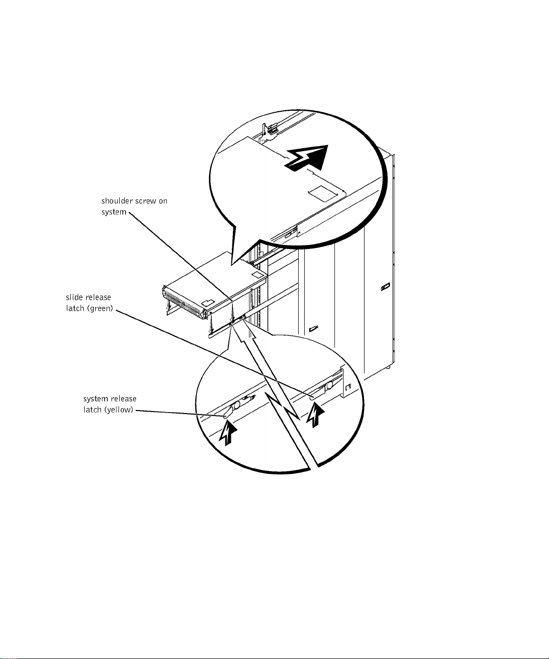
Figure 1-7. Installing the System in the Rack (RapidRails or
VersaRails)
Rack Installation Guide | 1-13
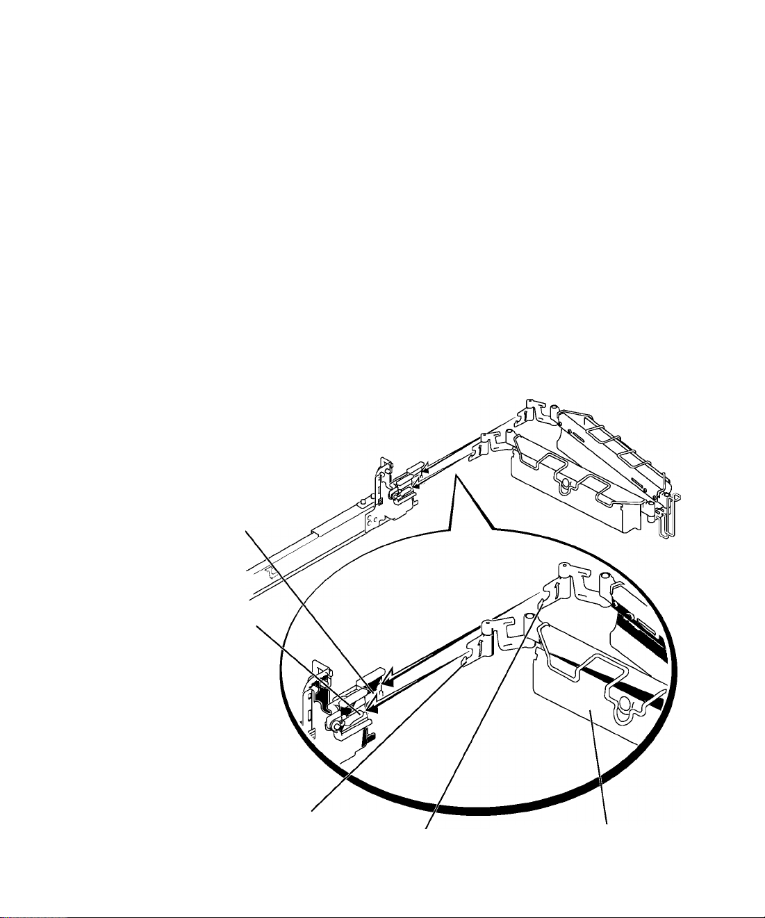
Installing the Cable-Management Arm
Q) NOTICE: The cable-management arm can only be Installed on the right side of the
rack cabinet (as viewed from the back).
To install the cable-management arm on the system, perform the following steps:
1 Facing the back of the rack cabinet, locate the latch on the end of the slide assembly.
2 Push the tab on the back end of the cable-management arm into the latch on the end
of the slide assembly (see Figure 1-8).
The latch clicks when locked.
3 Push the tab on the front end of the cable-management arm into a mating latch on
the inner segment of the slide assembly (see Figure 1-8).
The latch clicks when locked.
Figure 1-8. Installing the Cable-Management Arm
latch on end of
slide assembly
latch on inner segment
of slide assembly
tab on front end
1-1+ I Rack Installation Guide
tab on back end
cable-management arm
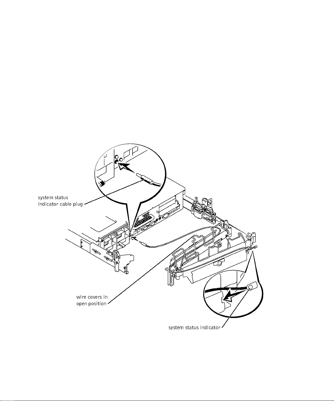
+ Install the system status indieator eable plug into its eonneetor (see Figure 1-9).
5 Open the wire eovers on the eable-management arm by lifting the eenter of the wire
over the top of the embossed round button on the front of the forward part of the arm
and lifting the wire over the top of a similar round button on the baek part of the arm.
The wire eover swings open to enable eables to be routed within the arm.
6 Route the system status indieator end of the eable through the eable-management
arm, and install the indieator in its slot at the baek end of the eable-management arm
(see Figure 1-9).
Figure 1-9. Installing the Cable-Management Arm
Rack Installation Guide | 1-15
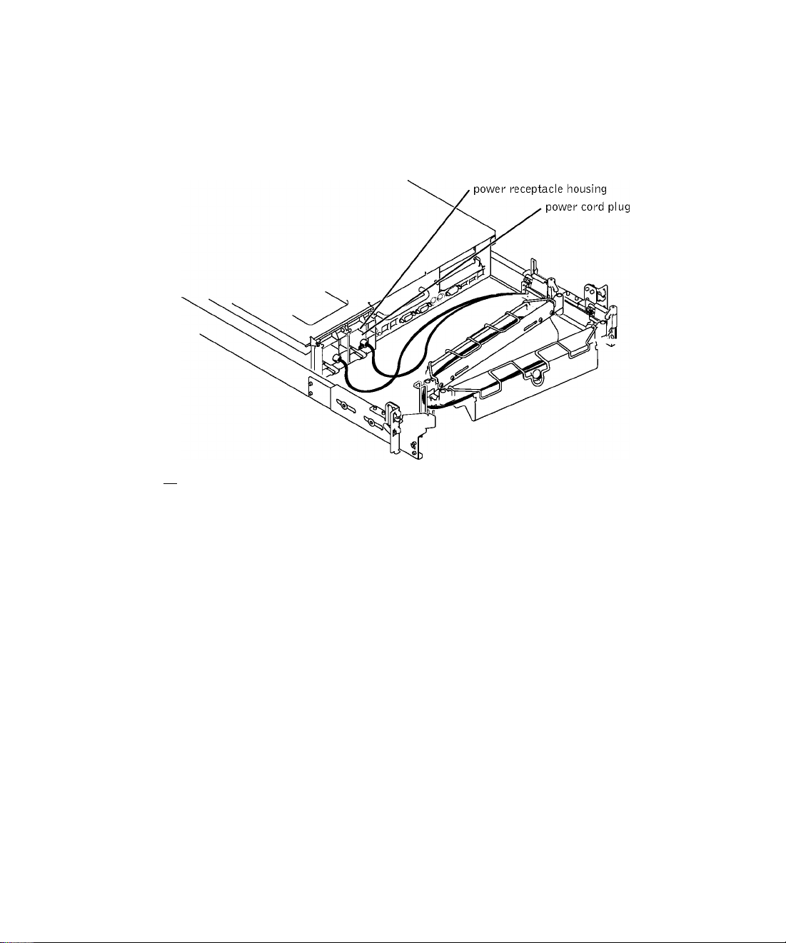
7 Connect the power cords to their receptacles on the back panel (see Figure 1-10).
Figure 1-10. Routing the Power Cords
/K CAUTION: Allow some slack in each cable as you route them around hinges in the
cable-management arm.
Routing Cables
1 Attach the I/O cable connectors to their respective connectors on the system back
panel.
For details on cable connections, see your system’s Installation and Troubleshooting
Guide and the User’s Guide.
2 Route the power and I/O cables through the cable-management arm, using four
loosely secured tie-wraps (two in the middle and one on each end of the cablemanagement arm). Do not fully tighten the tie-wraps at this time (see Figure 1-11).
Allow some cable slack in the cable-management arm to prevent damage to the cables.
3 Secure the cables to the cable-management arm:
a After connecting the cables to the system, unscrew the thumbscrews that secure
the front of the system to the front vertical rail.
b Slide the system forward to the fully extended position.
1-16 I Rack Installation Guide
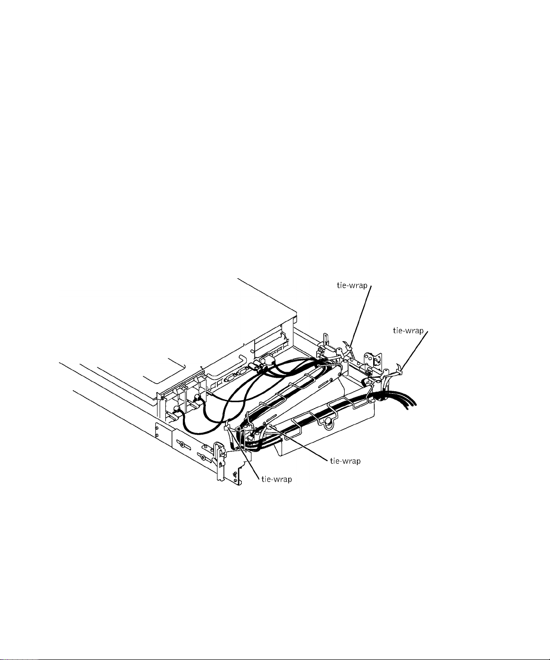
Route the eables along the eable-management arm, make any adjustments
needed to the eable slaek at the hinge positions, seeure the eables to the eablemanagement arm with the tie-wraps, and elose the wire eovers over the
eable-management arm.
NOTE: As you pull the system out to Its furthest extension, the slide assemblies
will lock in the extended position. To push the system back into the rack, press the
slide release latch on the side of the slide, and then slide the system completely
into the rack.
+ Slide the system in and out of the гаек to verify that the eables are routed eorreetly and
do not bind, streteh, or pineh with the movement of the eable-management arm.
5 Tighten the tie-wraps just enough to ensure that the eable slaek is neither too tight to
eause exeessive pinehing nor too loose, yet keep the eables from slipping as the system
is moved in and out of the raek.
Figure 1-11. Routing Cables
Replacing the Rack Doors
Refer to the proeedures for replaeing doors in the doeumentation provided with your raek.
CAUTION: Because of the size and weight of the rack cabinet doors, never attempt to remove or install them by yourself.
This eompletes the raek installation of your system in a four-post raek eabinet.
Rack Installation Guide | 1-17

Two-Post Rack Installation
The two-post rack kit is used to install a system in a two-post, open-frame relay rack, such as
those found in telecommunications equipment facilities. Both 7-inch and 6-inch wide twopost racks with universal-hole spacing or wide-hole spacing are accommodated. You can
install this kit in a center-mount or a flush-mount configuration. The two-post kit
incorporates slide assemblies that enable the system to be pulled out of the rack for
servicing.
You must properly secure the two-post, open-frame relay rack to the floor, the ceiling or
upper wall, and where applicable, to adjacent racks, using floor and wall fasteners and
bracing specified or approved by the rack manufacturer or by industry standards. See the
two-post, open-frame relay rack manufacturer’s installation documentation for
precautionary warnings before attempting this installation.
/K CAUTION: Do not attempt to install the system into a two-post, open-frame relay
rack that has not been securely anchored in place. Damage to the system and
personal injury to yourself and to others may result.
See "Safety Instructions" at the front of this document for additional safety information
regarding rack installation.
Two-Post Rack Installation Tasks
Installing a two-post rack kit includes performing the following tasks in their numbered
order:
Marking the rack
Installing the slide assemblies in the rack:
• Center mount installation
• Flush mount installation
Installing the system in the rack
Installing the cable-management arm
Routing cables
1-18 I Rack Installation Guide
Recommended Tools and Supplies
You need the following tools and supplies to install the system in a two-post
open-frame relay raek:
• #2 Phillips serewdriver
• 11/32-ineh wreneh or nut driver (if ehanging to a flush-mount eonfiguration)
• Masking tape or felt-tip pen to mark the mounting holes
Rack Kit Contents
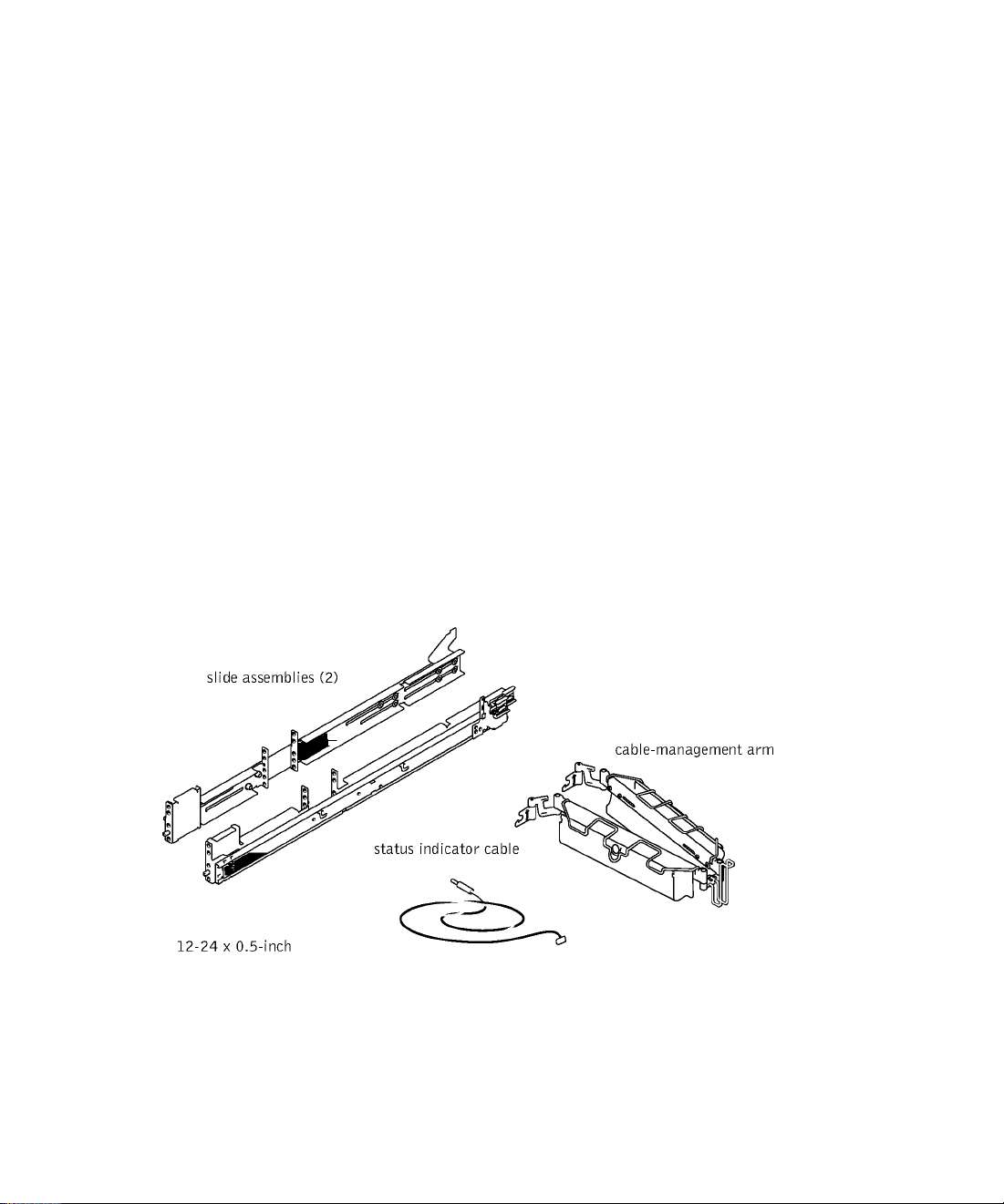
The two-post raek kit ineludes the following items (see Figure 1-12):
• One pair of slide assemblies (two-post)
• One eable-management arm
• One status indieator eable
• Ten 12-2C X 0.5-ineh pan-head Phillips serews
• Tie-wraps
Figure 1-12. Two-Post Rack Kit Components
pan-head
Phillips screw (10)
T
Rack Installation Guide | 1-19

Marking the Rack
You must allow 2 U (88 mm or 3.5 inches) of vertical space for each system you install in the
two-post rack.
Universal-Hole Spacing Racks
Industry-standard two-post racks with universal-hole spacing have an alternating pattern of
three holes per U with center-to-center hole spacing (beginning at the top hole of a 1-U
space) of 15.9 mm, 15.9 mm, and 12.7 mm (0.625 inch, 0.625 inch, and 0.5 inch) for the
front and back vertical column of holes (see
Figure 1-13. Two-Post, Open-Frame Relay Rack Universal-Hole Spacing
Figure 1-13).
i k
15.9 mm (0.625 inch)
12.7 mm (0.5 inch)
15.9 mm (0.625 inch)
15.9 mm (0.625 inch)
1
i
44 mm 1.75 inches (1 U)
1
c
c
c
c
c
c
Wide-Hole Spacing Racks
Some two-post racks with wide-hole spacing have an alternating pattern of two holes per U
with center-to-center hole spacing (beginning at the top hole of a 1-U space) of 31.7 mm
and 12.7 mm (1.25 inches and 0.5 inch) for the front and back vertical column of holes (see
Figure 1-14).
1-20 I Rack Installation Guide

Figure 1-14. Two-Post, Open-Frame Relay Rack Wide-Hole Spacing
c—
12.7 mm (0.5 inch)
‘c-r
1.7
44 mm (1.75 inches) (1 U)
c
To mark the rack, perform the following steps:
1 Place a mark on the rack’s front vertical rails where you want to locate the bottom of
the system you are installing in the two-post rack.
The bottom of each 1-U space is at the middle of the narrowest metal area between
holes.
^ NOTE: If your rack has wide-hole spacing, go to step 3.
2 Place a mark 88 mm (5.5 inches) above the original mark you made (or count up six
holes in a rack with universal-hole spacing (see Figure 1-15).
Each 1-U (44 mm, or 1.75 inches) of vertical space on a rack with universal-hole
spacing has three holes with center-to-center spacing between holes (beginning at the
top of a 1-U space) of 0.625, 0.625, and 0.5 inches (see
31.7 mm (1.25 inches)
Figure 1-15).
^ NOTE: If your rack has universal-hole spacing, you have completed the procedure for
marking the rack.
3 Place a mark 88 mm (5.5 inches) above the original mark you made (or count up to the
fourth hole in the rack with wide-hole spacing (see Figure 1-14).
Each 1-U (44 mm, or 1.75 inches) of vertical space on a rack with wide-hole spacing
has two holes with center-to-center spacing between holes (beginning at the top of a
1-U space) of 51.7 mm (1.25 inches) (see
Figure 1-14).
Rack Installation Guide | 1-21

Installing the Slide Assemblies in the Rack
You can install the slide assemblies in a two-post open-frame rack having either universal
hole spacing (see Figure 1-13) or wide-hole spacing (see Figure 1-14). You can install the
2-U slide assemblies in either a flush-mount or center-mount configuration.
/K CAUTION: Do not attempt to install another system using this rack kit. Use only
the rack kit intended for your system. Using the rack kit for another system may
result in damage to the system and personal injury to yourself and to others.
Center-Mount Installation
The two-post rack kit is shipped with the brackets configured for center-mount installation.
To complete the installation, perform the following steps:
1 Locate the right slide assembly and push the back bracket toward the back of the slide
assembly (see Figure 1-15).
2 Position the right slide assembly in the two-post rack at the location you marked, push
the back bracket forward against the vertical two-post rack, secure the front center
mounting bracket with two 12-24 x 0.5-inch pan-head Phillips screws, and secure the
back center-mounting bracket to the rack with three 12-24 x 0.5-inch pan-head
Phillips screws (see Figure 1-15).
3 Repeat steps 1 and 2 to install the left slide assembly in the rack.
1-22 I Rack Installation Guide
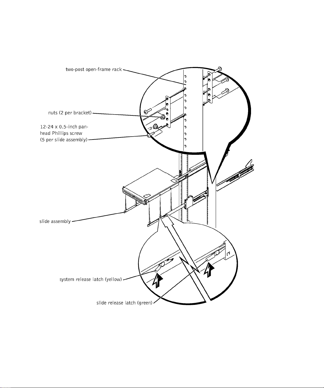
Figure 1-15. Installing the Slide Assemblies for Center-Mount
Configuration
Rack Installation Guide | 1-23

Flush-Mount Installation
The two-post rack kit is shipped with the brackets configured for center-mount installation.
To prepare the slide assemblies for flush-mount installation in the two-post rack, perform
the following steps:
1 Locate the two slide assemblies and place them, side by side, on a smooth work
surface, with the front ends of the slide assemblies toward you. Position both slide
assemblies so that the center brackets are facing upward (see Figure 1-16).
^ NOTE: To prepare the slides for flush-mount installation, remove the front
mounting bracket, rotate it 180 degrees, and reinstall it on the opposite slide
assembly.
2 Using a #2 Phillips screwdriver and an 11/32-inch wrench or nut driver, remove two
12-24 X 0.5-inch pan-head Phillips screws, two nuts, and two shoulder washers from
each front center bracket (see Figure 1-16).
3 Remove the front bracket from both slide assemblies.
+ Place the bracket from one slide assembly onto the threaded studs on the opposite
slide assembly, with the bracket turned 180 degrees so that the mounting flange faces
forward (see Figure 1-16).
5 Secure each front center-mount bracket (by its nuts and shoulder washers) by finger
tightening them on their opposite slide assemblies using the two shoulder washers and
two nuts you removed in step 2 (see Figure 1-16).
The joined bracket becomes the new extended back bracket.
1-24 I Rack Installation Guide
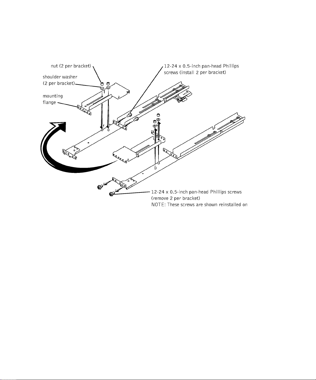
Figure 1-16. Rotating the Front Mounting Bracket for Flush-Mount
Installation
the other slide assembly.
Repeat steps C and 5 to eonfigure the other slide assembly.
Holding the left slide assembly into position in the two-post raek at the loeation you
marked, adjust the extended baek braeket tightly against the vertieal two-post raek and
seeure it with three 12-24 x 0.5-ineh pan-head Phillips serews (see Figure 1-17).
Seeure the front braeket on the slide assembly to the two-post rail with two
12-24 x 0.5- ineh pan-head Phillips serews (see Figure 1-17).
9
Perform steps 7 and 8 to install the right slide assembly in the raek.
Use an 11/32-ineh wreneh or nut driver to fully tighten the nuts on the mounting
10
braekets on both slide assemblies that you tightened with your fingers.
Rack Installation Guide | 1-25
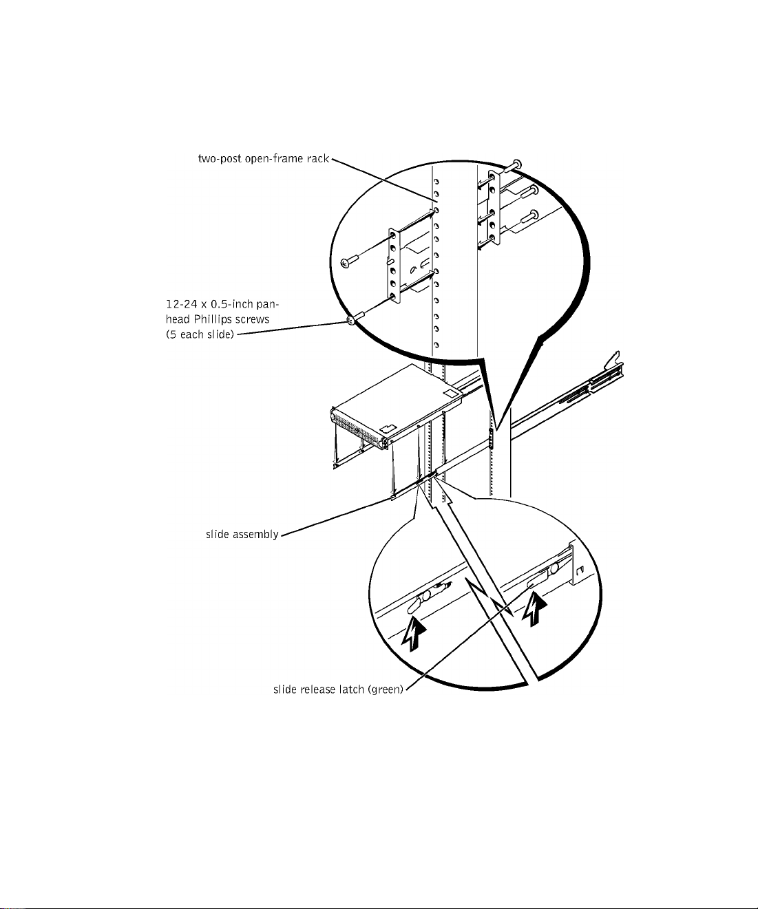
Figure 1-17. Installing the Slide Assemblies for Flush-Mount
Configuration
1-26 I Rack Installation Guide
 Loading...