

Page 1

Dell™ PowerVault™ NAS Systems SCSI Cluster
Installation and Troubleshooting Guide
Getting Started
Preparing Your Systems for Clustering
Cabling Your Cluster Hardware
Maintaining Your Cluster
Using MSCS
Troubleshooting
Cluster Data Sheet
Abbreviations and Acronyms
Notes, Notices, and Cautions
NOTE: A NOTE indicates important information that helps you make better use of your computer.
NOTICE: A NOTICE indicates either potential damage to hardware or loss of data and tells you how to avoid the
problem.
CAUTION: A CAUTION indicates a potential for property damage, personal injury, or death.
Abbreviations and Acronyms
For a complete list of abbreviations and acronyms, see "Abbreviations and Acronyms."
Information in this document is subject to change without notice.
© 2003 Dell Inc. All rights reserved.
Reproduction in any manner whatsoever without the written permission of Dell Inc. is strictly forbidden.
Trademarks used in this text: Dell, the DELL logo, PowerEdge, PowerVault, and Dell OpenManage are trademarks of Dell Inc.; Microsoft, Windows,
Windows NT, and MS-DOS are registered trademarks of Microsoft Corporation; Intel and Pentium are registered trademarks of Intel Corporation;
Novell and NetWare are registered trademarks of Novell Corporation.
Other trademarks and trade names may be used in this document to refer to either the entities claiming the marks and names or their products.
Dell Inc. disclaims any proprietary interest in trademarks and trade names other than its own.
Initial release: 26 Aug 2003
Page 2
Back to Contents Page
Getting Started
Dell™ PowerVault™ NAS Systems SCSI Cluster Installation and Troubleshooting Guide
Intended Audience
Obtaining Technical Assistance
Overview of NAS Clusters
NAS Cluster Features
NAS Cluster Components
Minimum System Requirements
Other Documents You May Need
This guide provides information for installing, configuring, and troubleshooting a Dell™ PowerVault™ network attached storage
(NAS) system's hardware and software components in a cluster configuration and provides information about the
configuration listed in Table 1-1
Table 1-1. PowerVault NAS System SCSI Cluster Configuration
.
Systems RAID
Controllers
Two PowerVault NAS
systems
The information in this guide includes:
Basic SCSI cluster installation procedures, which include:
Preparing NAS and storage systems for clustering
Cabling the cluster configuration
Installation procedures for installing the Microsoft® Windows® Storage Server 2003, Enterprise Edition operating
systems in your cluster configuration
Configuring the cluster peripherals, including PERC cards and network adapters
Installation procedures for installing a SCSI cluster configuration in your corporate network
Cluster upgrading and maintenance procedures
Information about the Microsoft Cluster Service (MSCS), the clustering software built into the operating systems
NOTE: Hereafter, Microsoft Cluster Service is also known as MSCS.
PERC 3/DC
PERC 4/DC
Storage Systems Operating System
Up to four PowerVault 21xS or 22xS
storage systems
Microsoft® Windows® Storage Server 2003,
Enterprise Edition
Troubleshooting procedures
Data sheets for recording critical cluster configuration information
See the Dell PowerVault NAS Systems SCSI Cluster Platform Guide for information about supported configurations.
NOTE: Dell and Microsoft support only the specific configurations described in the Platform Guide.
Page 3

Intended Audience
This guide addresses two audience levels:
Users and system installers who will perform general setup, cabling, and configuration of the PowerVault NAS Cluster
components
Trained service technicians who will perform more extensive installations, such as firmware upgrades and installation of
required expansion cards
Obtaining More Information
See "Obtaining Technical Assistance" and "Overview of NAS Clusters" for a general description of PowerVault NAS SCSI
clusters and clustering technology.
See "Using MSCS
operating system.
" for an overview of the clustering software built into the Windows Storage Server 2003, Enterprise Edition
Obtaining Technical Assistance
Dell Enterprise Training and Certification is available; see www.dell.com/training for more information. This service may
not be offered in all locations.
Overview of NAS Clusters
The PowerVault NAS SCSI cluster implements clustering technology on PowerVault NAS systems based on the Windows
Storage Server 2003, Enterprise Edition operating system. PowerVault NAS clusters provide the following benefits in meeting
the needs of mission-critical network application programs:
High availability — Clustering technology built into Microsoft Cluster Service (MSCS) ensures that system services
and resources are available to network clients if a cluster node fails for any reason.
Redundant storage — Application data can be stored on a maximum of four PowerVault storage systems.
Cluster share failure recovery — Cluster shares run on virtual servers, which can be failed over to another cluster
node if a node fails for any reason.
Zero impact on network resources — Cluster nodes can be repaired, serviced, upgraded, or replaced without taking
the entire cluster offline.
PowerVault NAS systems provide an easy-to-install solution for ensuring high-availability of your network storage resources
for Windows and UNIX® clients. Novell® NetWare® and Apple resources are also supported. However, if a system running
NetWare or Apple resources fails for any reason, you must manually restart their dependent resources. This procedure does
not corrupt the share data.
A NAS cluster provides a failover solution for the NAS systems, thereby ensuring a higher availability of network resources
than a nonclustered NAS system. The NAS cluster consists of the following components:
PowerVault NAS systems — Two homogeneous (identical) PowerVault NAS systems with the Windows Storage
Server 2003, Enterprise Edition operating system installed on each system
Cluster interconnect cable — An Ethernet crossover cable (cluster interconnect) connected to a network adapter in
Page 4

both systems
Storage systems — One to four PowerVault 21xS or 22xS storage systems
Each cluster node is configured with software and network resources that enable it to interact with the other node to provide
a mutual redundancy of operation and application program processing. Because the systems interact in this way, they appear
as a single system to the network clients.
As an integrated system, the PowerVault NAS Cluster is designed to dynamically handle most hardware failures and prevent
downtime. In the event that one of the cluster nodes fails for any reason, the processing workload of the failed node switches
over (or fails over) to the remaining node in the cluster. This failover capability enables the cluster system to keep network
resources and application programs up and running on the network while the failed node is taken offline, repaired, and
brought back online. The failover process is transparent and network clients experience only a momentary delay in accessing
their resources. After the failed node is repaired, the network resources can be transferred back to the original node, if
desired.
NOTE: When a cluster node running the Windows Storage Server 2003, Enterprise Edition operating system fails, the
NFS files shares running on the failed node are moved to the remaining node in the cluster and restarted. When a
cluster node with Novell NetWare shares or Apple shares fails, the file shares running on the failed node are converted
to file directories and moved to the remaining node in the cluster. To access the data in the failed-over directories, you
must manually reconfigure the file directories to file shares.
The availability of network services is critical to applications in a client/server environment. Clustering reduces the amount of
downtime caused by unexpected failures, providing maximum uptime of mission critical applications—also known as high
availability—that surpasses the capabilities of a stand-alone system. Using MSCS, clustering ensures that applications on a
failed cluster node continue on the remaining node(s) by migrating and managing the required resource to another node in
the cluster. Clusters that reduce the amount of system downtime are known as high availability clusters.
Configuring Active and Passive Cluster Nodes
Cluster configurations may include both active and passive cluster nodes. Active nodes are nodes that support the cluster
workload by processing application requests and providing client services. Passive nodes are backup nodes that support the
active nodes in the event of a hardware or software failure, thereby ensuring that client applications and services are highly
available.
NOTE: Passive nodes must be configured with the appropriate processing power and storage capacity to support the
resources that are running on the active nodes.
NAS SCSI cluster solutions running Windows are limited to active/active and active/passive configurations because this
solution supports two nodes.
An active/active configuration is a cluster with virtual servers running separate applications or services on each node. When
an application is running on node 1, the remaining cluster node does not have to wait for node 1 to fail. The remaining cluster
node can run its own cluster-aware applications (or another instance of the same application) while providing failover
capabilities for the resources on node 1.
An active/passive configuration is a cluster where the active cluster node is processing requests for a clustered application
while the passive cluster node simply waits for the active node to fail.
Active/passive configurations are more costly in terms of price and performance because one cluster node remains idle all of
the time. This configuration is appropriate for business-critical systems since the application can use all the resources of a
standby cluster node in case one active cluster node fails.
Cluster Node Limitations
The Windows Powered operating system installed on your cluster nodes is dedicated to file server operations. Because your
PowerVault NAS Cluster is a dedicated file server, the cluster nodes cannot be used in the following capacities:
Page 5

Primary Domain Controller (PDC)
NOTE: If another domain controller is not available on the network, you can configure a NAS cluster node as a domain
controller for the NAS cluster. However, client systems outside of the NAS cluster cannot be included as members of
the NAS cluster domain.
Windows Internet Naming Service (WINS) server
Dynamic Host Configuration Protocol (DHCP) server
Domain Name System (DNS) server
Microsoft Exchange Server
Microsoft Structured Query Language (SQL) server
Network Information Service (NIS) server
NAS Cluster Features
The PowerVault NAS cluster solution provides a high level of availability that is not available in nonclustered PowerVault NAS
systems. Because of the differences between clustered and nonclustered systems, compare the features in the clustered
PowerVault NAS systems to ensure that they meet your specific needs.
Table 1-2
provides a comparison of the features in both clustered and nonclustered PowerVault NAS systems.
Table 1-2. NAS Cluster Features
Features Clustered PowerVault
NAS Systems
Failover capability Yes No
Server Message Block (SMB) Yes Yes
SMB share failover Yes No
Dell OpenManage™ Array Manager
management
Monitor and keyboard required Yes No
Failover SCSI storage Yes No
Snapshot functionality Yes Yes
Optional Directory Quotas Yes Yes
Network File System (NFS) shares failover Yes No
Failover internal SCSI storage No No
Novell NetWare share failover No No
Yes Yes
Nonclustered PowerVault
NAS Systems
Apple shares failover No No
Simplified disk and volume management No Yes
Online volume expansion Yes Yes
NAS Cluster Components
Page 6

The following subsections describe the components that are common to the PowerVault NAS cluster, as well as the
components that are specific to each cluster system.
Table 1-3
lists the common components that are used in a PowerVault NAS cluster.
Table 1-3. Cluster Components
Component Description
NAS
systems
Shared
storage
system
Network
adapters
Two identical PowerVault 770N or 775N NAS systems in a homogeneous pair with the Windows Storage
Server 2003, Enterprise Edition operating system installed in each system.
NOTE: Dell or Microsoft can support only the specific configurations described in the Dell PowerVault NAS
SCSI Cluster Platform Guide.
Up to four PowerVault 21xS storage systems with dual SCSI expander management modules (SEMMs) or up
to four PowerVault 22xS with dual enclosure management modules (EMMs).
Supported network adapters for the public LAN.
PowerVault NAS-Specific Network Components
Table 1-4 describes the required components for each PowerVault NAS system.
Table 1-4. PowerVault NAS-Specific Network Components
Hardware
Component
Hot-spare
drive
support
RAID
controller(s)
RAID
support
Shared
storage
system(s)
Network
adapters
Description
Support for 1-inch SCSI hot-pluggable spare drives.
One of the following PERC RAID controller(s) installed in each PowerVault NAS system for the cluster's shared
storage:
PERC 3/DC
PERC 4/DC
Support for RAID 1, 5, and 1+0 levels.
RAID 1+0 is supported in a single enclosure or spanning two enclosures with hot-spare drives. RAID 0 and
independent drive configurations can be installed in a PowerVault NAS cluster. Because they do not offer data
redundancy if a disk fails, they are not recommended for a high-availability system.
NOTE: Dell and Microsoft support only the specific configuration described in the Dell PowerVault NAS SCSI
Cluster Platform Guide.
Up to four PowerVault 21xS storage systems with dual SEMMs or up to four PowerVault 22xS with dual
EMMs.
Two or more network adapters installed in each PowerVault NAS system for the node-to-node cluster
interconnect.
If two network adapters are not installed in the PowerVault 770N NAS system, you must install an additional
network adapter for the private network. PowerVault 775N NAS systems are preconfigured with two onboard
network adapters, which meets the minimum requirements.
NOTE: The network adapters must be identical on both systems.
NOTE: Dell and Microsoft support only the specific configuration described in the Dell PowerVault NAS SCSI
Page 7

Cluster Platform Guide.
Crossover
cable
Keyboard
and monitor
One Ethernet crossover cable for the node-to-node cluster interconnect (private network).
A keyboard and monitor are required for troubleshooting the cluster nodes.
RAID Controllers
Table 1-5 lists the Dell PowerEdge™ Expandable RAID controllers (PERC) that are used to connect the PowerVault 770N and
775N systems to external PowerVault storage systems. See the PERC documentation included with your system for a
complete list of features.
NOTE: Table 1-5 lists the RAID controllers that are connected to the external storage system(s). Your NAS system
also contains an internal RAID controller that is used to manage the system's internal hard drives.
Table 1-5. RAID Controller Features
Feature PERC 3/DC PERC 4/DC
SCSI channels 2 2
SCSI data transfer rate Up to 160 MB/s per channel Up to 320 MB/s per channel
Maximum number of drives per
channel
RAID levels RAID 0, 1, 1+0, 5, and 5+0 RAID 0, 1, 1+0, 5, and 5+0
Number of supported logical drives
and arrays
Cache 128 MB 128 MB
NOTE: RAID 0 and independent drives are possible but are not recommended for a high-availability system because they do
not offer data redundancy if a disk failure occurs.
14 14
Up to 14 logical drives and 32 arrays per
controller
Up to 14 logical drives and 32 arrays per
controller
PowerVault NAS System Specific Network Components
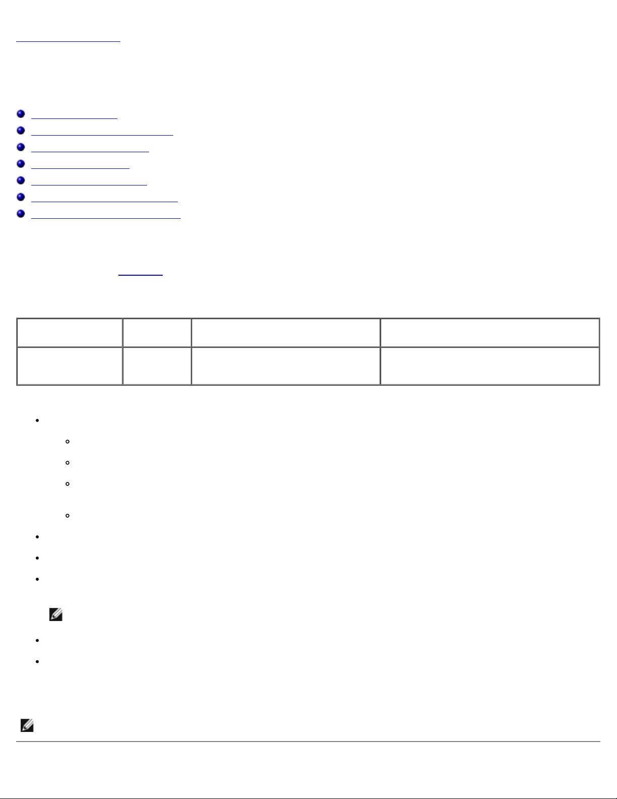
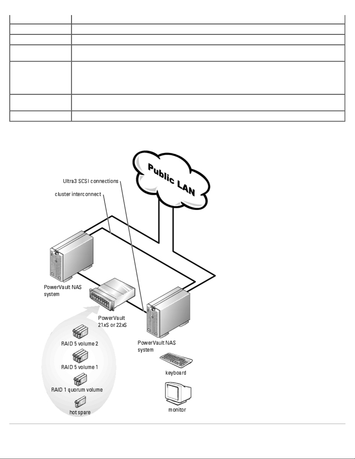
Figure 1-1 shows a sample configuration of the PowerVault 770N SCSI cluster components and cabling. Figure 1-2 shows a
similar sample configuration for the PowerVault 775N SCSI cluster.
See the Platform Guide for system-specific configuration information.
Figure 1-1. PowerVault 770N Cluster Solution
Page 8
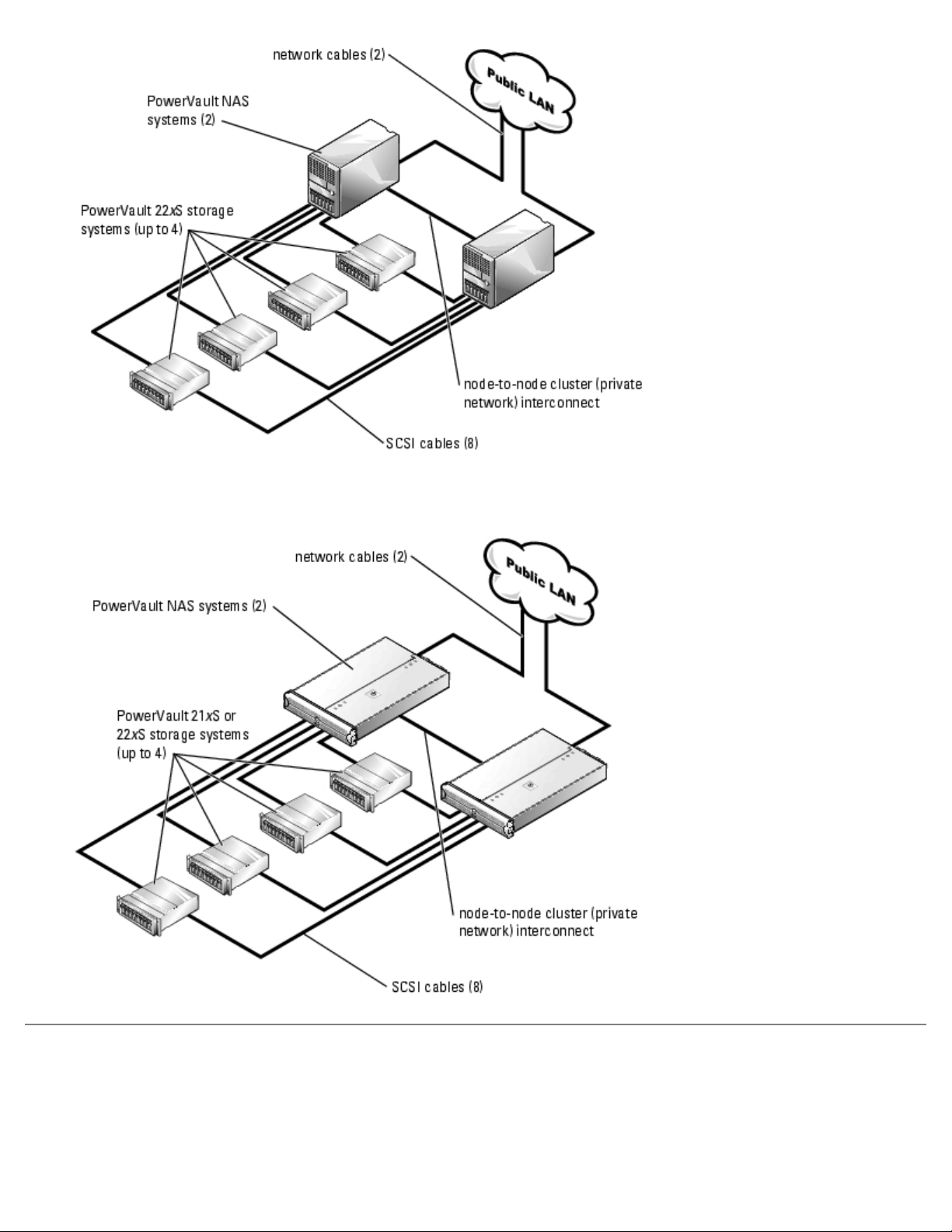
Figure 1-2. PowerVault 775N Cluster Solution
Minimum System Requirements
If you are installing a new PowerVault NAS SCSI cluster or upgrading an existing system to a PowerVault NAS SCSI cluster,
review the previous subsections to ensure that your hardware components meet the minimum system requirements listed in
the following section.
Page 9

PowerVault NAS Cluster Minimum System Requirements
PowerVault NAS SCSI cluster configurations require the following hardware and software components:
Cluster nodes
Cluster storage
Cluster interconnects (private network)
Client network connections (public network)
Operating system and storage management software
Cluster Nodes
Table 1-6 lists the hardware requirements for the cluster nodes.
Table 1-6. Cluster Node Requirements
Component Minimum Requirement
Cluster
nodes
Processors One or two processors on both cluster nodes.
RAM At least 512 MB of RAM installed on each cluster node.
RAID
controllers
Network
adapters
Two homogeneous (identical) PowerVault 770N or 775N NAS systems that support clusters in homogeneous
pairs.
NOTE: Both cluster nodes must be configured with the same number of processors.
One of the following PERC RAID controllers installed in each system for the cluster's shared storage:
PERC 3/DC
PERC 4/DC
Up to two PERCs per cluster node may be used for the cluster's shared storage.
Two disk drives are required for mirroring (RAID 1) and at least three disk drives are required for disk
striping with parity (RAID 5).
Two or more network adapters installed in each PowerVault NAS system for the node-to-node cluster
interconnect.
If two network adapters are not installed in the PowerVault 770N NAS system, you must install an additional
network adapter for the private network. PowerVault 775N NAS systems are preconfigured with two onboard
network adapters, which meets the minimum requirements.
NOTE: The network adapters must be identical on both systems.
NOTE: Dell and Microsoft support only the specific configuration described in the Dell PowerVault NAS SCSI
Cluster Platform Guide.
Private
network
cables
If you are using Fast Ethernet network adapters for the private network, connect a crossover Ethernet cable
between the network adapters in both cluster nodes.
If you are using Gigabit Ethernet network adapters for the private network, connect a standard Ethernet cable
between the network adapters in both cluster nodes.
Cluster Storage
Page 10

Table 1-7 provides the minimum requirements for the shared storage system(s).
Table 1-7. Cluster Shared Storage System Requirements
Hardware
Component
Shared storage
system(s)
Minimum Requirement
Up to four PowerVault 21xS or 22xS enclosures (for the shared disk resource) with the following
configuration:
Two SEMMs for each PowerVault 21xS
Two EMMs for each PowerVault 22xS
Redundant power supplies connected to separate power sources
At least two SCSI hard drives in each PowerVault 21xS or 22xS enclosure to support hardwarebased RAID functionality
Currently, MSCS supports only the Windows NT File System (NTFS) format for the shared storage
system.
Two volumes are the minimum requirement for an active/active cluster configuration (where the
active nodes process requests and provide failover for each other)
See "Configuring Active and Passive Cluster Nodes
active/passive cluster configurations.
Two 1-, 4-, 8-, or 20-m SCSI cables for each PowerVault 21xS or 22xS storage system in the
cluster
Cluster Interconnects (Private Network)
" for more information on active/active and
Table 1-8 provides the minimum requirements for the cluster interconnects (private network).
Table 1-8. Cluster Interconnects (Private Network) Requirements
Hardware
Component
Network
adapters
Ethernet
switch
(optional)
Ethernet
cables
Ethernet
switch
cabling
(optional)
Minimum Requirement
Any network adapter supported by the system for each cluster node. The network adapters for the private
network must be identical and supported by the system.
NOTE: Dual-port Fast Ethernet network adapters are not recommended for simultaneous cluster connections
to the public and private networks. When you configure the network adapter in MSCS Setup to All
Communications, the public network can provide redundancy for node-to- node traffic in the case of a
failure in the private network segment.
One Ethernet switch for the private network (cluster interconnect).
One standard or crossover Ethernet cable.
Standard Ethernet cable (not included with the Dell Cluster kit) connects two copper Gigabit Ethernet
(1000 BASE-T) network adapters.
Crossover Ethernet cable connects two fast 100 Mb/s Ethernet network adapters.
Additional Ethernet cables (not included) may be used to attached to an Ethernet switch for the public
network (client connections) and private network (cluster interconnect).
Client Network Connections (Public Network)
Page 11

The cluster connections to the public network (for client access of cluster resources) require one or more identical network
adapters supported by the system for each cluster node. Configure this network in a mixed mode (All Communications) to
communicate the cluster heartbeat to the cluster nodes if the private network fails for any reason.
Other Documents You May Need
The System Information Guide provides important safety and regulatory information. Warranty information may be
included within this document or as a separate document.
The Platform Guide provides information about the platforms that support the NAS SCSI cluster configuration.
The Rack Installation Guide and Rack Installation Instructions document that was included with your rack solution
describes how to install your system into a rack.
The Getting Started Guide provides an overview of initially setting up your system.
The User's Guide for your PowerVault system describes system features and technical specifications, SCSI drivers, the
System Setup program (if applicable), software support, and the system configuration utility.
The Installation and Troubleshooting Guide for your PowerVault system describes how to troubleshoot the system and
install or replace system components.
The Dell PowerVault 77xN NAS Systems Administrator's Guide provides system configuration, operation, and
management information.
The Dell PowerVault 200S, 201S, 210S, and 211S Storage Systems Installation and Service Guide describes how to
install and troubleshoot the PowerVault 200S, 201S, 210S, and 211S storage systems and install or replace system
components.
The Dell PowerVault 220S and 221S System Installation and Troubleshooting Guide describes how to install and
troubleshoot the PowerVault 220S and 221S storage systems and install or replace system components.
The PERC documentation includes information on the SCSI RAID controller.
The Dell OpenManage™ Array Manager documentation provides instructions for using the array management software
to configure RAID systems.
Documentation for any components you purchased separately provides information to configure and install these
options.
Updates are sometimes included with the system to describe changes to the system, software, and/or documentation.
NOTE: Always read the updates first because they often supersede information in other documents.
Release notes or readme files may be included to provide last-minute updates to the system documentation or
advanced technical reference material intended for experienced users or technicians.
Back to Contents Page
Page 12
Back to Contents Page
Preparing Your Systems for Clustering
Dell™ PowerVault™ NAS Systems SCSI Cluster Installation and Troubleshooting Guide
Before You Begin Configuring the Shared Disks
Installation Overview
Selecting a Domain Model Installing and Configuring MSCS
Configuring Windows Networking
Assigning Static IP Addresses to Your Cluster Resources
and Components
Installing a PERC RAID Controller Using Shadow Copies of Shared Folders
Installing and Configuring the Shared Storage System Installing the Cluster Management Software
Installing a PowerVault 770N NAS Cluster Minimum
Configuration
Installing a PowerVault 775N NAS Cluster Minimum
Configuration
Before You Begin
Configuring Cluster Networks Running Windows Storage
Server 2003, Enterprise Edition
Configuring and Managing the Cluster Using Cluster
Administrator
Managing Directory Quotas (Optional)
Creating a System State Backup
1. Ensure that your site can handle the power requirements of the cluster equipment.
Contact your sales representative for information about your region's power requirements.
CAUTION: Only trained service technicians are authorized to remove and access any of the components
inside the system. See your System Information Guide for complete information about safety precautions,
working inside the computer, and protecting against electrostatic discharge.
2. Ensure that the following components are installed in each PowerVault NAS system in the cluster:
Network adapters
PERC cards
SCSI hard drives
Any additional peripheral components
HBA drivers
You can download the latest drivers from the Dell Support website at support.dell.com.
NOTE: Both NAS systems and the hardware components in each system must be identical.
3. Ensure that the following components are installed in each Dell™ PowerVault™ 21xS or 22xS system in the cluster:
Two SEMMs (PowerVault 21xS only) or two EMMs (PowerVault 22xS only)
A split-bus module
SCSI hard drives
Page 13

See "Installing and Configuring the Shared Storage System" for more information.
4. Cable the system hardware for clustering.
See "Cabling Your Cluster Hardware
5. Configure the storage system(s) as described in your storage system documentation.
6. Configure the PERC cards as described in your PERC card documentation.
7. Configure RAID for the internal SCSI hard drives, configure the hard drives using the controller's BIOS utility or Dell
OpenManage™ Array Manager.
" for more information.
Installation Overview
This section provides installation overview procedures for configuring your cluster running the Microsoft® Windows® Storage
Server 2003 operating system.
1. Ensure that your cluster meets the requirements as described in "Before You Begin
2. Select a domain model that is appropriate for your corporate network and operating system.
See "Selecting a Domain Model
3. Reserve static IP addresses for your cluster resources and components.
" for more information.
."
The resources and components include:
Public network
Private network
Cluster virtual servers
See "Assigning Static IP Addresses to Your Cluster Resources and Components
4. Install or update the PERC drivers.
The PERC drivers allow your cluster nodes to communicate with the shared storage systems.
See "Updating the PERC Card Driver
5. Configure the hard drives on the shared storage system(s).
See "Configuring and Managing Virtual Disks" for more information.
6. Configure the MSCS software.
" for more information.
" for more information.
The MSCS software is the clustering component of the Windows operating system that provides the failover capabilities
for the cluster.
See "Installing and Configuring MSCS
" for more information.
Page 14

7. Verify cluster functionality. Ensure that:
Your cluster components are communicating properly with each other.
MSCS is started.
See "Verifying Cluster Functionality
8. Verify cluster resource availability.
Use Cluster Administrator to check the running state of each resource group.
See "Verifying Cluster Resource Availability
The following sections provide detailed information for each step in the "Installation Overview
Windows operating system.
NOTE: Dell strongly recommends that you use the "PowerVault SCSI Cluster Solution Data Sheet" during the
installation of your cluster to ensure that all installation steps are completed. The data sheets are located in "Cluster
Data Sheet."
" for more information.
" for more information.
" that is specific to your
Selecting a Domain Model
On a cluster running the Windows Storage Server 2003, Enterprise Edition operating system, both cluster nodes must belong
to a common domain or directory model. The following membership configurations are supported:
Both cluster nodes are member systems in a Windows 2000 Active Directory domain.
Both cluster nodes are member systems in a Windows Storage Server 2003 Active Directory domain.
One node is a domain controller and the other node is a member of the domain, without other member systems or
clients in the domain.
If a cluster node cannot contact a domain controller, the node will not be able to authenticate client requests.
Configuring Windows Networking
You must configure the public and private networks in each node before you install MSCS. The following sections introduce
you to some principles and procedures necessary to the networking prerequisites.
Assigning Static IP Addresses to Your Cluster Resources and
Components
A static IP address is an Internet address that a network administrator assigns exclusively to a system or a resource. The
address assignment remains in effect until it is changed by the network administrator.
The IP address assignments for the public LAN segments will depend on the configuration of your environment. If the IP
assignments are set up correctly, all of the network adapter resources will respond to ping commands and appear online
Page 15

before and after you install MSCS. If the IP assignments are not set up correctly, the cluster nodes may not be able to
communicate with the domain. See "Troubleshooting" for more information.
appear online after you install MSCS. If the IP address resources are not set up correctly, the cluster nodes may not be able
PowerVault NAS SCSI cluster configurations running the Windows operating system require static IP addresses assigned to
hardware and software applications in your cluster, as listed in Table 2-1
.
Table 2-1. Applications and Hardware Requiring IP Address Assignments
Application/Hardware Description
Cluster IP address The cluster IP address is used for cluster management and must correspond to the cluster name.
Because each server has at least two network adapters, the minimum number of static IP
addresses required for a cluster configuration is five (one for each network adapter and one for
the cluster). Additional static IP addresses are required when MSCS is configured with application
programs that require IP addresses.
Cluster-aware
applications running on
the cluster
Cluster node network
adapters
For example, these applications may include a network file system (NFS) share, server message
block (SMB) file share, or a general purpose file share.
The network adapters are used to connect to the public and private networks.
For cluster operation, two network adapters are required: one network adapter for the public
network (LAN/WAN) and another network adapter for the private network (sharing heartbeat
information between the cluster nodes).
See "Cabling Your Cluster Hardware
NOTE: To ensure cluster operations during a DHCP server failure, Dell recommends using static
IP addresses for your cluster.
" for more information about cluster interconnect options.
Configuring IP Addresses for the Private Network (Cluster
Interconnect)
Having two network adapters connected to separate networks on the cluster provides a contingency solution for cluster
communication failure. If the private network (cluster interconnect) fails, MSCS can default cluster node communications
through the public network, thereby ensuring that failover capabilities are possible in the event of a cluster node failure.
The network adapters installed in each cluster node on the private network (cluster interconnect) must reside on different IP
subnets. Having a separate IP subnet or a different network ID than the LAN subnet(s) used for client connectivity ensures
that both the public and private network communications do not interfere with each other.
If you are connecting the cluster node network adapters together using an Ethernet cable, Dell recommends using the static
IP address assignments in Table 2-2
for the network adapters that are connected to the private network.
Table 2-2. Sample Static IP Address Assignments for the Private Network
Cluster Node IP Address Subnet
Node 1 10.0.0.1 255.255.255.0
Node 2 10.0.0.2 255.255.255.0
If you are connecting multiple network adapters together for the private network using a network switch, ensure that each
network adapter connected to a private network is assigned a unique IP address. For example, you can continue the IP
address scheme in Table 2-2
private network that are connected to the same switch.
NOTE: The IP address assignments for the public LAN segment(s) depend on the configuration of your environment.
If the IP assignments are set up correctly, all of the network adapter resources will respond to ping commands and will
by using 10.0.0.3 and 10.0.0.4 for additional cluster nodes and the network adapters for the
Page 16

to communicate with the domain and the Cluster Configuration Wizard may not allow you to configure all of your networks.
See "Troubleshooting" for more information on troubleshooting problems.
NOTE: Additional fault tolerance for the LAN segments can be achieved by using network adapters that support
adapter teaming or by having multiple LAN segments. Do not use fault tolerant network adapters for the cluster
interconnect, as these network adapters require a dedicated link between the cluster nodes.
Creating Separate Subnets for the Public and Private Networks
The network adapters for the public and private networks that are installed in the same cluster node must reside on separate
IP subnetworks. Therefore, the private network used to exchange heartbeat information between the cluster nodes must have
a separate IP subnet or a different network ID than the public network, which is used for client connections.
Setting the Network Interface Binding Order
1. Click the Start button, select Control Panel, and double-click Network Connections.
2. Click the Advanced menu, and then click Advanced Settings.
The Advanced Settings window appears.
3. In the Adapters and Bindings tab, ensure that the Private and Public connections are at the top of the list.
To change the connection order:
a. Click Public or Private.
b. Click the up-arrow or down-arrow to move the connection to the top or bottom of the Connections box.
c. Click OK.
d. Close the Network Connections window.
Using Dual-Port Network Adapters for the Private Network
Using a dual-port network adapter, you can configure your cluster to use the public network as a failover for private network
communications. However, to ensure high-availability and redundancy in your NAS cluster, configure the public and private
networks on two separate network adapters. For example, you can configure an internal network adapter port for the private
network and a PCI network adapter port for the public network.
NOTE: Configuring the public and private network on a dual-port network adapter is not supported.
Verifying Cluster Network Communications
To ensure proper cluster operations, the cluster nodes must be able to communicate with each other through the private
network (cluster interconnect). This communication involves the exchange of heartbeat messages, whereby the two cluster
nodes inquire about each other's status, or "health," and acknowledge each inquiry.
To verify network communications between the cluster nodes:
1. Open a command prompt on each cluster node.
Page 17

2. At the prompt, type:
ipconfig /all
3. Press <Enter>.
All known IP addresses for each local server appear on the screen.
4. Issue the ping command from each remote system.
Ensure that each local server responds to the ping command.
Installing a PERC RAID Controller
You can install a PERC controller in your PowerVault NAS systems to manage your external storage systems. When you install
a RAID controller in your system, install the controller in the correct PCI slot. Some PCI slots on your system are connected to
different PCI buses with varying I/O configurations (for example, 32-bit, 32-MHz vs. 64-bit, 32-MHz) that might affect the
data transfer rate from your RAID controller to your shared storage system. Install the RAID controller in the recommended
PCI slot.
See the Platform Guide for more information about your system's PCI bus configuration.
See "RAID Controllers
" for a list of supported RAID controllers.
Updating the PERC Card Driver
See the Dell Support website at support.dell.com to download the latest Windows driver for the PERC card.
To update the default driver to the latest PERC driver:
1. Click the Start button, select Programs, select Administrative Tools, and click Computer Management.
2. Select System Tools, select Device Manager, and click the plus (+) sign to expand SCSI and RAID controllers.
One or more PERC cards are listed.
3. Right-click the PERC card, select Properties, select the Driver tab, and then click Update Driver to start the
Windows Device Driver wizard.
4. Click Next to proceed to the Install Hardware Device Drivers dialog box.
5. Select Display a list of known drivers for this device... and then click Next.
6. Click Have Disk, insert the diskette or the Dell OpenManage Server Assistant CD that contains Dell's updated driver,
specify the location of the driver (A:> or D:>), and then click OK.
7. Select the appropriate RAID controller (PERC card) and click Next.
8. Click Next to begin the installation.
9. When the installation is complete, click Finish to exit the wizard.
10. Click Close to exit the Properties window.
11. Click Yes to restart the system.
Page 18

12. Repeat this procedure for cluster node 2.
Installing and Configuring the Shared Storage System
Clustering PowerVault Storage Systems
If you are upgrading an existing PowerVault 21xS or 22xS storage system to meet the cluster requirements for the shared
storage system, you may need to install additional hard drives and/or one of the following management modules in the
shared storage system:
SCSI SEMM (PowerVault 21xS only)
EMM (PowerVault 22xS only)
The size and number of drives you add depends on the RAID level you want to use, the number of hard drives installed in
your system, and the number of application programs you want to run in your cluster environment.
See the Dell PowerVault 200S, 201S, 210S, and 211S Storage Systems Installation and Service Guide or the Dell PowerVault
220S and 221S System Installation and Troubleshooting Guide for information about installing the hard drives in the
PowerVault 22xS storage system.
NOTE: In cluster mode, the last slot (SCSI ID 15) in the PowerVault 22xS is not used; SCSI ID 15 is used for the
primary EMM.
Configuring the PowerVault 21xS Storage System for Cluster Mode
To ensure that both NAS systems recognize all the drives in the storage system, you must enable forced-joined mode on the
SEMMs installed in each storage system that you will share between the two storage systems for clustering. This mode
prevents the storage system from operating in a dual-bus split backplane configuration (2 x 4 or 2 x 6) when two cables are
attached.
The SEMMs are identified by a label adjacent to the SCSI connector. Two identical SEMMs installed in each storage system are
required for cluster operation. You cannot use one SEMM.
See the Dell PowerVault 200S, 201S, 210S, and 211S Storage Systems Installation and Service Guide for more information
on installing and configuring the SEMMs.
To configure the SEMMs for forced join mode:
1. Locate the two-pin jumper labeled "FORCED JOINED JP8" on the SEMM, as shown in Figure 2-1
The SEMM is shipped with a jumper plug that is connected to only one jumper pin.
.
Figure 2-1. SEMM Configuration
Page 19
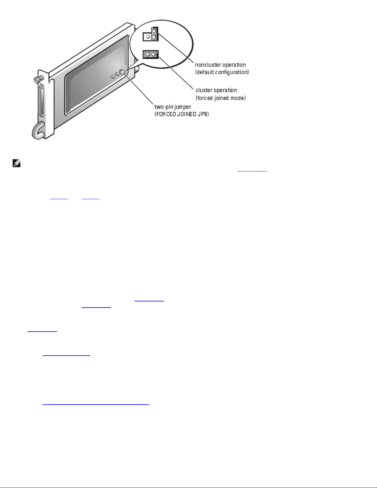
NOTE: Only the FORCED JOINED JP8 jumper contains a jumper plug. The Dell-installed default for jumpers JP1, JP2,
JP6, and JP7 is a noncluster operation (default configuration), as shown in Figure 2-1
2. Move the jumper plug to connect the two pins of the FORCED JOINED JP8 jumper.
3. Repeat step 1 and step 2 for the second SEMM.
4. Install the two SEMMs in the PowerVault 21xS storage system.
.
Configuring the PowerVault 22xS Storage System for Cluster Mode
To ensure that both systems recognize all the drives in the storage system, you must set the split-bus configuration switch to
cluster mode on the PowerVault 22xS storage system before turning on the storage system.
To configure the storage system in cluster mode:
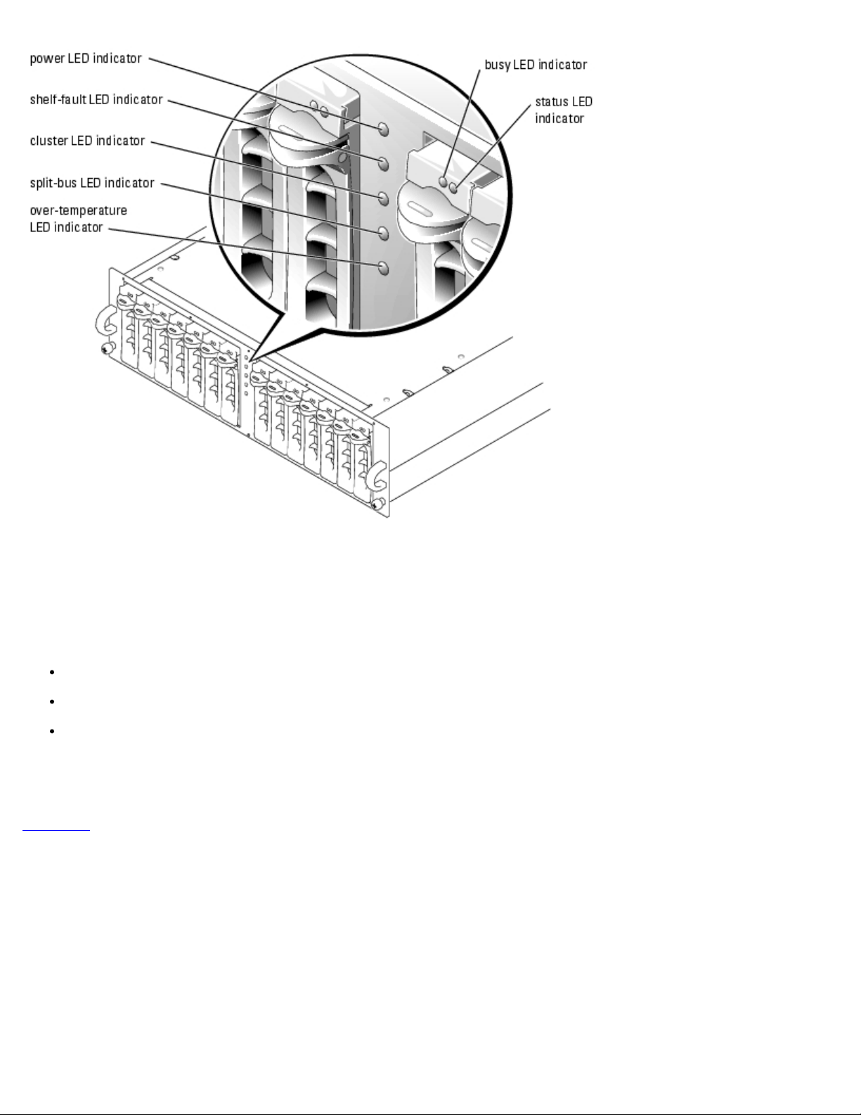
1. Set the bus configuration switch (see Figure 2-2
LED indicator (see Figure 2-3
Figure 2-3
221S System's User's Guide for more information.
See "Split-Bus Module
2. Install the split-bus module in the PowerVault 22xS storage system.
3. Install the two EMMs in the PowerVault 22xS storage system.
See "Enclosure Management Module (EMM)
Installation and Troubleshooting Guide for information about installing EMMs.
illustrates the front panel indicators on the storage system's front panel. See the Dell PowerVault 220S and
" for more information about the split-bus module.
) indicates that the storage system is in cluster mode.
) on the split-bus module to cluster mode (down position). The cluster
" for basic information about EMMs; see the Dell PowerVault 220S and 221S
Figure 2-2. Back-Panel Module Features and Indicators
Page 20
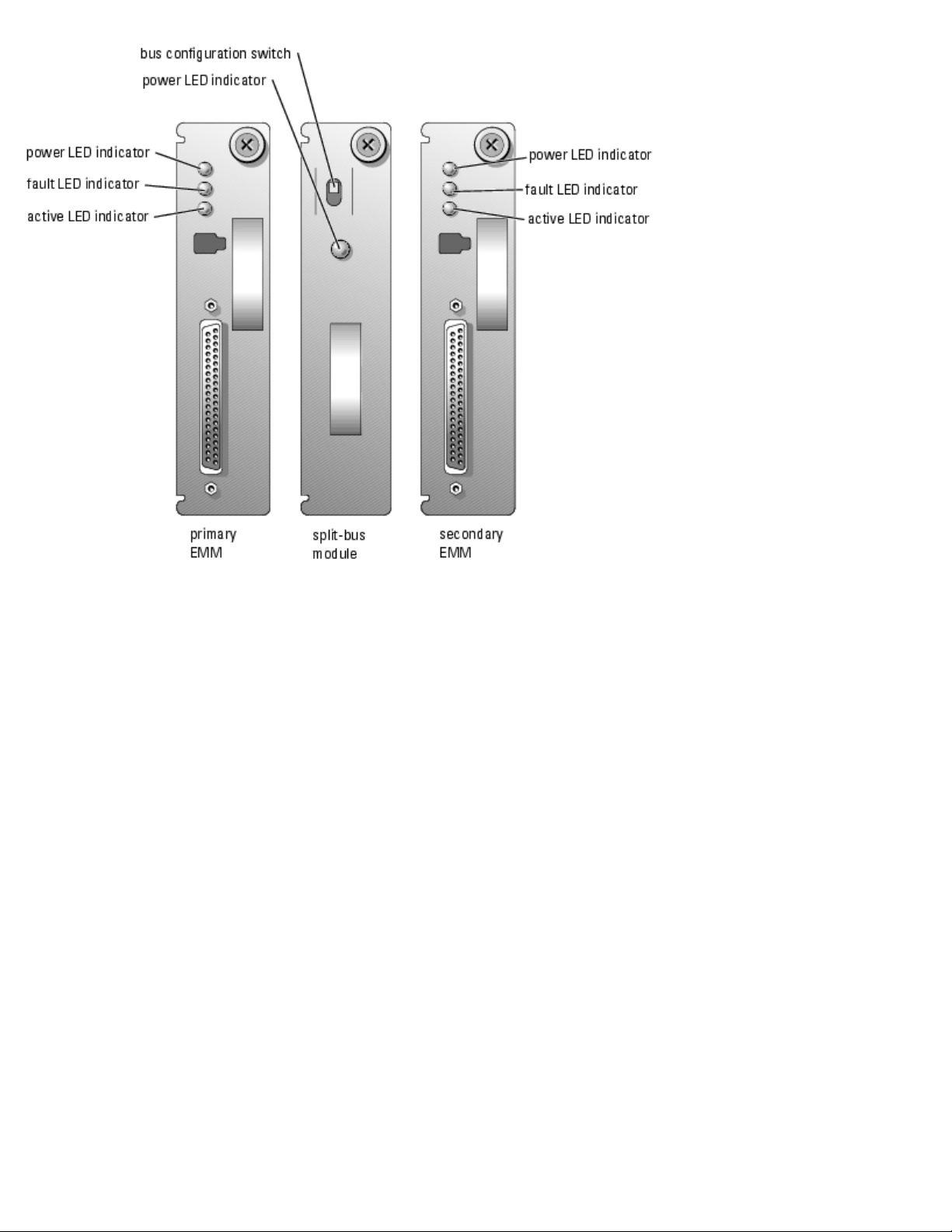
Figure 2-3. Front Panel Features and Indicators
Page 21
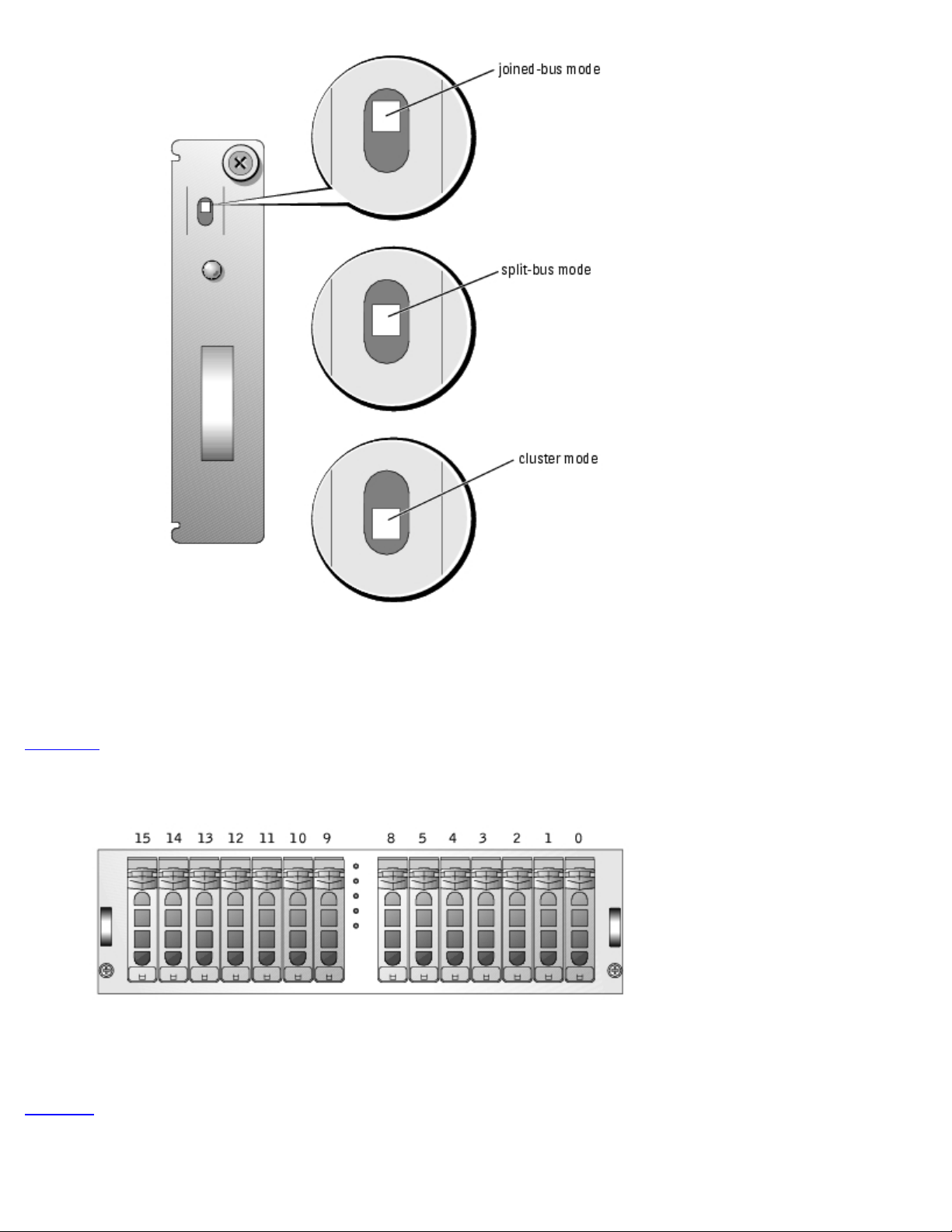
Split-Bus Module
Your system supports three SCSI bus modes controlled by the split-bus module:
Joined-bus mode
Split-bus mode
Cluster mode
These modes are controlled by the position of the bus configuration switch when the system is turned on.
Figure 2-4 illustrates the switch position for each mode.
Figure 2-4. Bus Configuration Switch Modes
Page 22
The only difference between cluster mode and joined-bus mode is the SCSI ID occupied by the enclosure services processor.
When cluster mode is detected, the processor SCSI ID changes from 6 to 15, allowing a second initiator to occupy SCSI ID 6.
As a result, SCSI ID 15 is disabled, leaving 13 available hard drives in cluster mode. As a result, you must remove the SCSI
ID 15 hard drive from the enclosure when using the enclosure in cluster mode.
Figure 2-5
illustrates the SCSI IDs and their associated hard drives for the PowerVault 22xS storage system.
Figure 2-5. PowerVault 22xS SCSI ID Numbers and Associated Drives
See your Dell PowerVault 220S and 221S Systems Installation and Troubleshooting Guide for more information about SCSI ID
assignments and cluster mode operation.
Table 2-3
provides a description of the split-bus module modes and functions.
Table 2-3. Split-bus Module Modes and Functions
Page 23

Mode Position of
Bus
Configuration
Switch
Function
Joinedbus
mode
Splitbus
mode
Cluster
mode
The split-bus module has only one LED indicator (see Figure 2-2
receiving power.
Up LVD termination on the split-bus module is disabled, electrically joining the two SCSI buses to
form one contiguous bus. In this mode, neither the split-bus nor the cluster LED indicators on the
front of the enclosure are illuminated.
Center LVD termination on the split-bus module is enabled and the two buses are electrically isolated,
resulting in two seven-drive SCSI buses. The split-bus LED indicator on the front of the enclosure
is illuminated while the system is in split-bus mode.
Down LVD termination is disabled and the buses are electrically joined. The cluster LED on the front of
the enclosure is illuminated while the system is in cluster mode.
NOTE: To change the SCSI bus mode, you must change the position of the bus configuration switch before turning on
the storage system. Using the bus configuration switch while the system is on does not affect system operation. If you
change the bus configuration switch while the system is running, the change will not take effect until you perform the
following sequence: shut down the nodes, reboot the storage system, and then power up the nodes.
for location), which is illuminated when the module is
Enclosure Management Module (EMM)
The EMM serves two primary functions in your storage system:
SCSI bus expansion — Acts as a buffer for the SCSI bus, electrically dividing the bus into two independent segments
while logically allowing all SCSI bus traffic to pass through it transparently. The buffer improves the quality of the SCSI
signals and allows longer cable length connections.
Management functions — Includes SES and SAF-TE reporting to the host initiator, control of all enclosure LED
indicators, and monitoring of all enclosure environmental elements such as temperature sensors, cooling modules, and
power supplies.
A system with redundant enclosure management features two EMMs that are designated as primary and secondary and can
be configured in either a cluster, joined-bus, or split-bus mode. A nonredundant configuration consists of one EMM and one
SCSI terminator card, and can be configured in a joined-bus mode only. In a redundant system, only one EMM per SCSI bus
is active at one time, so only one EMM per SCSI bus can respond to SCSI commands from an initiator.
If a secondary EMM receives a message that the primary EMM has failed in joined-bus and cluster modes, the fault LED
indicator on the primary EMM is illuminated and the condition is reported back to the host initiator. The secondary EMM then
becomes active and holds the failed primary in a state of reset until it is replaced. If the primary EMM detects that the
secondary has failed, the secondary's fault LED indicator is illuminated and the failed status is reported back to the host
initiator.
NOTE: In split-bus mode, each EMM controls half of the enclosure. If one EMM fails in split-bus mode, the second EMM
reports the failure, but does not assume control of the entire SCSI bus.
The primary EMM is always plugged into the slot on the left (viewed from the back of the system). In a redundant joined-bus
configuration, the primary EMM assumes control of all the enclosure functionality. In addition, the primary EMM is the only
module that reports the status of the system to the host initiator through SES and SAF-TE protocols. Because the secondary
EMM must assume the responsibilities of the primary in the event that the primary fails, both the primary and secondary
EMMs are continuously monitoring the status of the system's components.
Preparing the PERC Card for Clustering
The warning message shown in Figure 2-6 appears on your screen when you attempt to modify the configuration of the
shared storage system on your cluster by using the PERC BIOS configuration utility.
Page 24
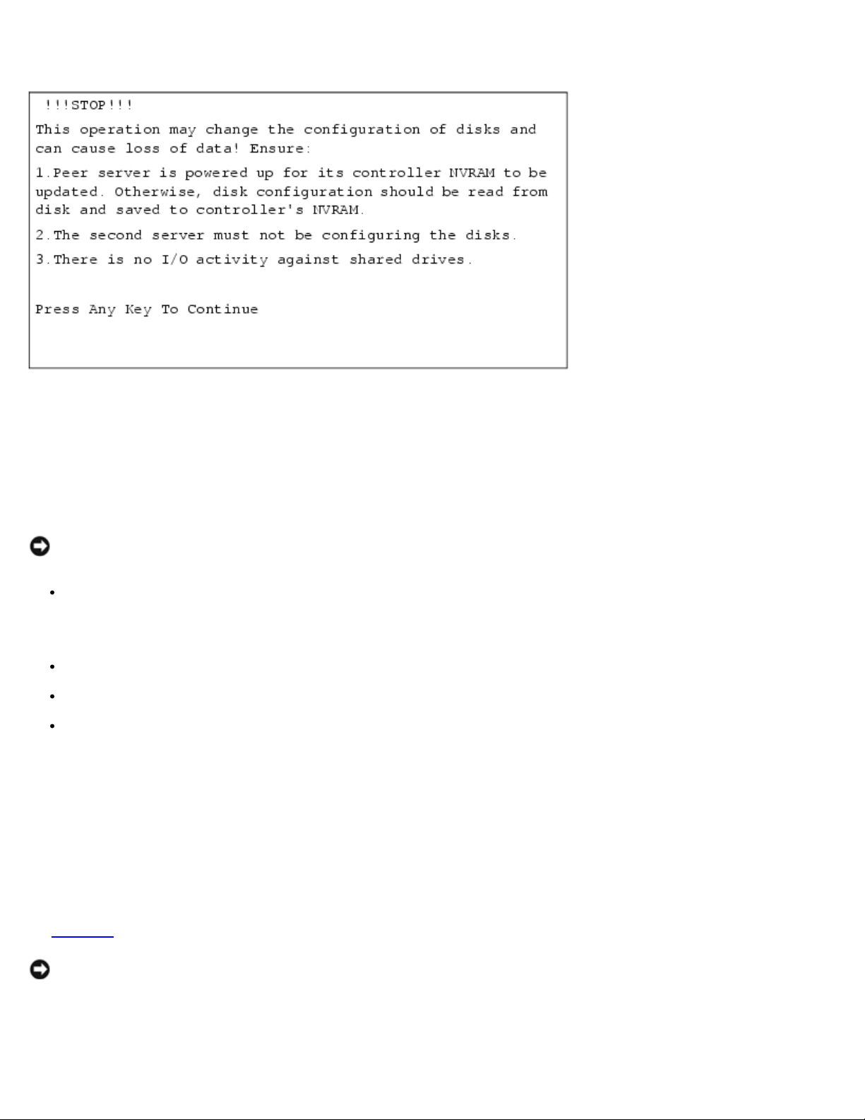
Figure 2-6. Important System Warning
The warning message appears on the screen immediately after activating the PERC BIOS configuration utility by pressing
<Ctrl><m> during the system's POST and when you attempt to perform a data-destructive operation in the Dell™
PowerEdge™ RAID Console utility. Examples of data-destructive operations include clearing the configuration of the logical
drives or changing the RAID level of your shared hard drives.
This warning message alerts you to the possibility of data loss if certain precautions are not taken to protect the integrity of
the data on your cluster.
NOTICE: To prevent data loss, your cluster must meet the conditions in the following bulleted list before you attempt
any data-destructive operation on your shared hard drives.
Ensure that the peer system is turned on during the operation so that the PERC card's NVRAM can be updated with the
new configuration information. Alternately, if the peer system is down, you must save the disk configuration to the
shared storage system. When you restart the system later, update the peer system's NVRAM from the disk
configuration saved to the shared storage system.
Ensure that the peer cluster node is not currently configuring the shared storage system.
Ensure that I/O activity does not occur on the shared storage system during the operation.
Ensure that your PERC firmware is the latest version. See your PERC documentation for information on downloading the
latest firmware.
Enabling the Cluster Mode Using the PERC Card
Each PERC card that is used to connect to a shared storage enclosure must have cluster mode enabled using the PERC card's
BIOS configuration utility. Enabling cluster mode implements the additional functionality required for the controller to operate
in a cluster environment.
See Table 2-3
NOTICE: If you replace your PERC card, ensure that you enable the cluster mode on the replacement PERC card and
set the SCSI ID to the appropriate value (6 or 7) before you connect the SCSI cables to the shared storage.
See the appropriate PERC card documentation for more information about enabling cluster mode and the SCSI host adapter.
for more information on split-bus module modes.
Page 25

Setting the SCSI Host Adapter IDs
After you enable cluster mode on the PERC card, you have the option to change the SCSI ID for both of the adapter's
channels. For each shared SCSI bus (a connection from a channel on one system's PERC card to the shared storage enclosure
to a channel on the second system's PERC card), you must have unique SCSI IDs for each controller. The default SCSI ID for
the PERC is ID 7. Thus, the SCSI ID for one of the system's PERC cards must be configured to ID 6.
For cluster configurations with two PERC cards in each node connected to shared storage enclosures, set both controllers in
one system to SCSI ID 6; that is, one node's pair of PERC cards utilizes SCSI ID 7 (default) and the other node's pair of PERC
cards is changed to utilize SCSI ID 6.
See the PERC documentation for more information about setting the SCSI host adapter ID number.
NOTICE: If you replace a PERC card, you must set the appropriate SCSI ID before you connect the SCSI cables to the
shared storage.
Configuring and Managing Virtual Disks
The hard drives in the shared storage system must be configured for clustering. Before you configure the virtual disks,
configure the RAID levels that you will be using in your cluster. See the PERC documentation and the Array Manager
documentation for instructions about setting up a RAID array.
All virtual disks, especially if they are used for the quorum resource, should incorporate the appropriate RAID level to ensure
high availability. See "Creating the Quorum Resource
" for more information on the quorum resource.
NOTE: Dell recommends that you use a RAID level other than RAID 0 (which is commonly called striping). RAID 0
configurations provide very high performance, but do not provide the necessary redundancy that is required for the
quorum resource. See the documentation for your storage system for more information about setting up RAID levels
for the system.
In a cluster configuration, if multiple NTFS partitions are created on a single virtual disk, these partitions will fail over
together. If you plan to run cluster-aware applications on each cluster node, you must create at least two separate virtual
disks to ensure that the applications can fail over independently.
Obtaining More Information
See "Naming and Formatting Drives on the Shared Storage System" for information on how to assign drives letters to the
shared hard drives in a cluster installation.
See the appropriate operating system documentation and the PERC documentation for instructions on partitioning and
formatting the shared storage system's hard drives.
Windows Storage Server 2003, Enterprise Edition Dynamic Disks and
Volumes
The Windows operating system does not support dynamic disks or volumes as shared cluster storage. If the shared cluster
storage is configured as a dynamic disk, the Cluster Configuration wizard will not be able to discover the disks, which
prevents the cluster and network clients from accessing the disks.
Naming and Formatting Drives on the Shared Storage System
Page 26

After the virtual disks are created, write the disk signature, assign drive letters to the virtual disks, and then format the
drives as NTFS drives. Format the drives and assign drive letters from only one cluster node.
NOTICE: Accessing the hard drives from multiple cluster nodes may corrupt the file system.
Assigning Drive Letters
NOTICE: If the disk letters are manually assigned from the second node, the shared disks are simultaneously
accessible from both nodes. To ensure file system integrity and prevent possible data loss before you install the MSCS
software, prevent any I/O activity to the shared drives by performing the following procedure on one node at a time,
and ensuring that the other node is shut down.
Before installing MSCS, ensure that both nodes have the same view of the shared storage systems. Because each node has
access to hard drives that are in a common storage array, each node must have identical drive letters assigned to each hard
drive. Up to 22 logical drive letters (E through Z) can be used for the shared storage systems.
NOTE: Drive letters A through D are reserved for the local system.
The number of drive letters required by individual servers in a cluster may vary. Dell recommends that the shared drives be
named in reverse alphabetical order beginning with the letter z.
To assign drive letters and format drives on the shared storage system:
1. With node 2 shut down, open Disk Management on node 1.
2. Allow Windows to enter a signature on all new physical or logical drives.
NOTE: Do not create dynamic disks on your hard drives.
3. Locate the icon for the first unnamed, unformatted drive on the shared storage system.
4. Right-click the icon and select Create from the submenu.
If the unformatted drives are not visible, verify the following:
The latest version of the PERC driver is installed.
The storage system is properly cabled to the servers.
The split-bus module on the PowerVault 22xS is set to cluster mode.
5. In the dialog box, create a partition the size of the entire drive (the default) and then click OK.
NOTE: The MSCS software allows only one node to access a logical drive at a time. If a logical drive is
partitioned into multiple disks, only one node is able to access all the partitions for that logical drive. If each
node must access a separate disk, two or more logical drives must be present in the storage system.
6. Click Yes to confirm the partition.
7. With the mouse pointer on the same icon, right-click and select Change Drive Letter and Path from the submenu.
8. Assign a drive letter to an NTFS volume or create a mount point.
To assign a drive letter to an NTFS volume:
a. Click Edit and select the letter you want to assign to the drive (for example, z).
Page 27

b. Click OK.
c. Go to step 9.
PowerVault 770N Two homogeneous (identical) PowerVault 770N NAS systems running the Windows Storage Server
To create a mount point:
a. Click Add.
b. Click Mount in the following empty NTFS folder.
c. Type the path to an empty folder on an NTFS volume, or click Browse to locate it.
d. Click OK.
e. Go to step 9
9. Click Yes to confirm the changes.
10. Right-click the drive icon again and select Format from the submenu.
11. Under Volume Label, enter a descriptive name for the new volume; for example, Disk_Z or Email_Data.
12. In the dialog box, change the file system to NTFS, select Quick Format, and click the Start button.
13. Click OK at the warning.
14. Click OK to acknowledge that the format is complete.
15. Click Close to close the dialog box.
16. Repeat step 3
17. Close Disk Management.
18. Shut down node 1.
19. Turn on node 2.
20. On node 2, open Disk Management.
21. Ensure that the drive letters for node 2 are correct.
.
through step 15 for each remaining drive.
To modify the drive letters on node 2, repeat step 7
through step 9.
Installing a PowerVault 770N NAS Cluster Minimum
Configuration
Table 2-4 provides the hardware requirements for a PowerVault 770N NAS cluster minimum configuration.
Figure 2-7
See "Minimum System Requirements
Table 2-4. PowerVault 770N NAS Cluster Minimum Configuration Hardware Requirements
Component Hardware Requirement
shows a minimum system configuration for a PowerVault 770N NAS Cluster.
" for more information.
Page 28
NAS systems 2003, Enterprise Edition operating system
Operating system Windows Storage Server 2003, Enterprise Edition
RAID controller One supported PERC installed in both systems
Shared storage
systems
Private network
cabling
Public network
cabling
Network adapter An additional network adapter installed in each NAS system for the private network
One PowerVault 21xS or 22xS storage system with at least nine hard drives reserved for the cluster
One crossover cable (not included) attached to a Fast Ethernet network adapter in both systems
OR
One standard cable (not included) attached to a Gigabit Ethernet network adapter in both systems
One standard cable attached to a network adapter in both systems for the public network
Figure 2-7. Minimum System Configuration of a PowerVault 770N NAS Cluster
Page 29

Installing a PowerVault 775N NAS Cluster Minimum
Configuration
The following cluster components are required for a minimum system cluster configuration using the PowerVault 775N NAS
Cluster:
Table 2-5
Figure 2-8
See "Minimum System Requirements
provides the hardware requirements for a PowerVault 775N NAS cluster minimum configuration.
shows a minimum system configuration for a PowerVault 775N NAS Cluster.
" for more information.
Table 2-5. PowerVault 775N NAS Cluster Minimum Configuration Hardware Requirements
Cluster Component Hardware Requirement
PowerVault 775N NAS
systems
Operating system Windows Storage Server 2003, Enterprise Edition
RAID controllers One supported PERC installed in both systems for the external storage system(s)
Shared storage systems One PowerVault 21xS or 22xS storage system with at least nine hard drives reserved for the
Private network cabling One Ethernet cable attached to a network adapter in both systems for the private network
Public network cabling One Ethernet cable attached to a network adapter in both systems for the public network
Two homogeneous (identical) PowerVault 775N NAS systems that support clusters
cluster
Figure 2-8. Minimum System Configuration of a PowerVault 775N NAS Cluster
Page 30

Configuring the Shared Disks
This section provides the steps for performing the following procedures:
Creating the quorum resource
Configuring the shared disk for the quorum disk
Configuring the shared disks for the data disks
Configuring the hot spare
Creating the Quorum Resource
When you install Windows Storage Server 2003, Enterprise Edition in your cluster, the software installation wizard
automatically selects the quorum resource (or quorum disk), which you can modify later using Cluster Administrator.
Additionally, you can assign a specific hard drive for the quorum resource. To prevent quorum resource corruption, Dell and
Microsoft recommend that you do not place data on the resource.
Page 31

The quorum resource is typically a hard drive in the shared storage system that serves the following purposes in a PowerVault
NAS Cluster configuration:
Acts as an arbiter between the cluster nodes to ensure that the specific data necessary for system recovery is
maintained consistently across the cluster nodes
Logs the recovery data sent by the cluster node
Only one cluster node can control the quorum resource at one time. This node continues to run if the two nodes are unable to
communicate with each other. If the two nodes are unable to communicate through the private network, MSCS automatically
shuts down the node that does not contain the quorum resource.
When one of the cluster nodes fails for any reason, changes to the cluster configuration database are logged to the quorum
resource, ensuring that the healthy node gaining control of the quorum resource has access to an up-to-date version of the
cluster configuration database.
Creating a Partition for the Quorum Resource
Dell recommends creating a separate partition—approximately 1 GB in size—for the quorum resource.
When you create the partition for the quorum resource:
Format the partition with NTFS.
Use the partition exclusively for your quorum logs.
Do not store any application data or user data on the quorum resource partition.
To properly identify the quorum resource, Dell recommends that you assign the drive letter "Q" to the quorum resource
partition.
Dell does not recommend using the remainder of the virtual disk for other cluster resources. If you do use the space for
cluster resources, be aware that when you create two volumes (partitions) on a single virtual disk, they will both fail over
together if a server fails.
Preventing Quorum Resource Failure
Because the quorum resource plays a crucial role in cluster operation, losing a quorum resource causes the entire cluster to
fail. To prevent cluster failure, configure the quorum resource on a RAID volume in the shared storage system.
NOTICE: Dell recommends that you use a RAID level other than RAID 0, which is commonly called striping. RAID 0
configurations provide very high performance, but they do not provide the level of redundancy that is required for the
quorum resource.
Configuring the Shared Disk for the Quorum Resource
1. Open Dell OpenManage Array Manager.
2. Locate two hard drives of the same size in the external storage system(s).
3. Create a RAID 1 virtual disk.
See your Array Manager documentation for information on installing a virtual disk.
Page 32

NOTE: After you create the virtual disk and the virtual disk is initialized by the PERC 3 controller, you must
reboot the system.
4. Write a signature on the new disk.
5. Using the new disk, create a volume, assign a drive letter, and format the disk in NTFS.
See your Array Manager documentation for information about configuring the shared disk.
Configuring the Shared Disks for the Data Disk(s)
1. Open Array Manager.
2. Locate three or more hard drives of the same size in the external storage system(s).
3. Create a RAID 5 virtual disk using at least three hard drives.
See your Array Manager documentation for information on installing a virtual disk.
NOTE: After you create the virtual disk and the virtual disk is initialized by the PERC 3 controller, you must
reboot the system.
4. Write a signature on the new disk.
5. Using the new disk, create a volume, assign a drive letter, and format the disk in NTFS.
To configure the shared disks for the data disks on data volume 2, repeat the steps for configuring the shared disks for other
data volumes.
Configuring the Hot Spare
The hot spare is a failover hard drive for any of the internal hard drives in the external storage system. If one of the hard
drives in the storage system fails, the responsibilities of the failed disk will automatically fail over to the hot spare.
1. Open Dell OpenManage Array Manager.
2. Assign a global hot spare disk.
See your Array Manager documentation for more information.
Configuring Cluster Networks Running Windows Storage Server
2003, Enterprise Edition
When you install and configure a cluster running Windows Storage Server 2003, Enterprise Edition, the software installation
wizard automatically assigns and configures the public and private networks for your cluster. You can rename a network,
allow or disallow the cluster to use a particular network, or modify the network role using Cluster Administrator. Dell
recommends that you configure at least one network for the cluster interconnect (private network) and one network for all
communications. Additionally, Dell recommends that you use a Gigabit Ethernet network adapter for the private network.
Page 33

Installing and Configuring MSCS
MSCS is an integrated service in the Windows Storage Server 2003, Enterprise Edition operating system. MSCS performs the
basic cluster functionality, which includes membership, communication, and failover management. When MSCS is installed
properly, the service starts on each node and responds automatically if one of the nodes fails or goes offline. To provide
application failover for the cluster, the MSCS software must be installed on both cluster nodes.
See "Using MSCS
NOTE: For systems with split backplane modules installed, the cluster installation tries to use the logical drives on the
secondary backplane as cluster disks. Because these drives are not accessible to all nodes in the cluster, ensure that
they are removed from the cluster after the installation is complete.
NOTE: In Windows Storage Server 2003, Enterprise Edition, mapping a network drive to the same drive letter as a
cluster disk resource renders the cluster disk inaccessible from Windows Explorer on the host. Ensure that mapped
network drives and cluster disks are never assigned the same drive letter.
" for more information.
Verifying Cluster Readiness
To ensure that your server and storage systems are ready for MSCS installation, ensure that these systems are functioning
correctly and verify the following:
All cluster servers are able to log on to the same domain.
The shared disks are partitioned and formatted, and the same drive letters that reference logical drives on the shared
storage system are used on each node.
For each attached PowerVault 22xS storage system, the split-bus module is set to cluster mode before power-up.
Cluster mode is enabled on all PERC cards connected to shared storage.
The controller's SCSI IDs (6 or 7) on each node are different.
All peer PERC cards are connected to the same PowerVault system through the same channel number.
All IP addresses and network names for each system node are communicating with each other and the rest of the
network. The private IP addresses should not be accessible from the LAN.
Configuring Microsoft Windows Storage Server 2003, Enterprise Edition
Cluster Service (MSCS)
The cluster setup files are automatically installed on the system disk.
To create a new cluster:
1. From either node, click the Start button, select Programs→ Administrative Tools, and then double-click Cluster
Administrator.
2. From the File menu, select Open Connection.
3. In the Action box of the Open Connection to Cluster, select Create new cluster.
The New Server Cluster Wizard appears.
4. Click Next to continue.
Page 34

5. Follow the procedures in the wizard, and then click Finish.
6. Add the second node to the cluster.
a. Turn on the remaining node.
b. Click the Start button, select Programs→ Administrative Tools, and double-click Cluster Administrator.
c. From the File menu, select Open Connection.
d. In the Action box of the Open Connection to Cluster, select Add nodes to cluster.
e. In the Cluster or server name box, type the name of the cluster or click Browse to select an available cluster
from the list, and then click OK.
The Add Nodes Wizard window appears.
If the Add Nodes Wizard does not generate a cluster feasibility error, go to step f
If the Add Nodes Wizard generates a cluster feasibility error, go to "Adding Cluster Nodes Using the Advanced
Configuration Option."
f. Click Next to continue.
g. Follow the procedures in the wizard, and then click Finish.
.
Adding Cluster Nodes Using the Advanced Configuration Option
If you are adding additional nodes to the cluster using the Add Nodes Wizard and the nodes are not configured with identical
internal storage devices, the wizard may generate one or more errors while checking cluster feasibility in the Analyzing
Configuration menu. If this situation occurs, select Advanced Configuration Option in the Add Nodes Wizard to add the
nodes to the cluster.
To add the nodes using the Advanced Configuration Option:
1. From the File menu in Cluster Administrator, select Open Connection.
2. In the Action box of the Open Connection to Cluster, select Add nodes to cluster, and click OK.
The Add Nodes Wizard window appears.
3. Click Next.
4. In the Select Computers menu, click Browse.
5. In the Enter the object names to select (examples), type the names of one to seven systems to add to the
cluster, with each system name separated by a semicolon.
6. Click Check Names.
The Add Nodes Wizard verifies and underlines each valid system name.
7. Click OK.
8. In the Select Computers menu, click Add.
9. In the Advanced Configuration Options window, click Advanced (minimum) configuration, and then click OK.
Page 35

10. In the Add Nodes window, click Next.
11. In the Analyzing Configuration menu, Cluster Administrator analyzes the cluster configuration.
If Cluster Administrator discovers a problem with the cluster configuration, a warning icon appears in Checking cluster
feasibility. Click the plus (+) sign to review any warnings, if needed.
12. Click Next to continue.
13. In the Password field of the Cluster Service Account menu, type the password for the account used to run MSCS,
and click Next.
The Proposed Cluster Configuration menu appears with a summary with the configuration settings for your cluster.
14. Click Next to continue.
The new systems (hosts) are added to the cluster. When completed, Tasks completed appears in the Adding Nodes
to the Cluster menu.
NOTE: This process may take several minutes to complete.
15. Click Next to continue.
16. In the Completing the Add Nodes Wizard, click Finish.
Verifying Cluster Functionality
To verify cluster functionality, monitor the cluster network communications to ensure that your cluster components are
communicating properly with each other. Also, verify that MSCS is running on the cluster nodes.
Verifying MSCS Operation
After you install MSCS, verify that the service is operating properly.
1. Click the Start button and select Programs→ Administrative Tools, and then select Services.
2. In the Services window, verify the following:
In the Name column, Cluster Service appears.
In the Status column, Cluster Service is set to Started.
In the Startup Type column, Cluster Service is set to Automatic.
Verifying Cluster Resource Availability
In the context of clustering, a resource is a basic unit of failover management. Application programs are made up of
resources that are grouped together for recovery purposes. All recovery groups, and therefore the resources that comprise
the recovery groups, must be online (or in a ready state) for the cluster to function properly.
To verify that the cluster resources are online:
Page 36

1. Start Cluster Administrator on the monitoring node.
2. Click the Start button and select Programs→ Administrative Tools (Common)→ Cluster Administrator.
3. Open a connection to the cluster and observe the running state of each resource group. If a group has failed, one or
more of its resources might be offline.
Configuring and Managing the Cluster Using Cluster
Administrator
Cluster Administrator is Microsoft's tool for configuring and managing a cluster. The following procedures describe how to run
Cluster Administrator locally on a cluster node and how to install the tool on a remote console.
Launching Cluster Administrator on a Cluster Node
1. Click the Start button and select Programs.
2. Select Administrative Tools.
3. Select Cluster Administrator.
Troubleshooting Failed Resources
Troubleshooting the failed resources is beyond the scope of this document, but examining the properties of each resource and
ensuring that the specified parameters are correct are the first two steps in this process. In general, if a resource is offline, it
can be brought online by right-clicking the resource and selecting Bring Online from the drop-down menu.
Obtaining More Information
See the Windows Storage Server 2003, Enterprise Edition documentation and online help for information about
troubleshooting resource failures.
See Microsoft's online help for configuring MSCS.
See "Using MSCS
" for more information about MSCS.
Managing Directory Quotas (Optional)
Directory Quota is an optional tool in the PowerVault NAS Manager that allows you to manage and control disk space
allocation on the server appliance. Using Directory Quota, you can add, delete, monitor and change space limits for specific
directories on your cluster nodes. The Administrator can configure the settings for Directory Quota in the PowerVault NAS
Manager, which are available and enforced in a failover scenario.
NOTE: Directory Quota monitors disk space for specific directories and does not monitor disk space for each individual
user. To enable quotas for each user, you must use Disk Quota.
In a cluster configuration, each cluster node can manage and configure Directory Quota for the volume(s) owned by the node.
Page 37

For example, if a cluster has two volumes and each node owns one of the volumes, a typical scenario in an active/active
configuration (where virtual servers are running on each node) would be:
Node 1 owns Volume G.
Node 2 owns Volume H.
In this configuration, the administrator must use the PowerVault NAS Manager connect to node 1 to configure the Directory
Quota settings for Volume G, and then connect to node 2 to configure the Directory Quota settings for Volume H.
See the Dell PowerVault NAS Systems—Installing Storage Manager for Server Appliances document located on the Dell
Support website at support.dell.com for information on installing Directory Quota in your PowerVault NAS Manager.
Using Shadow Copies of Shared Folders
A shadow copy is a point-in-time copy of a shared file or folder. If you change a file on the active file system after making a
shadow copy, the shadow copy contains the old version of the file. If an active file gets corrupted or deleted, you can restore
the old version by copying the file from the latest shadow copy or restoring a directory or file.
NOTICE: Shadow copies are temporary backups of your data that typically reside on the same volume as your data. If
the volume becomes damaged and you lose your data, the shadow copy is also lost. Do not use shadow copies to
replace scheduled or regular backups. Table 2-4 provides a summary of shadow copies.
See the Dell PowerVault 77xN NAS Systems Administrator's Guide for more information on shadow copies.
You can create shadow copies of shared folders that are located on shared resources, such as a file server. When creating
shadow copies of shared folders on a NAS SCSI cluster running the Windows Storage Server 2003, Enterprise Edition
operating system, note the information listed in Table 2-6
See the Microsoft Support website at www.microsoft.com for more information on shadow copies for shared folders.
.
Table 2-6. Creating Shadow Copies
Cluster
Type/Task
Single quorum
device cluster
Scheduled tasks
that generate
volume shadow
copies.
Description Action
Two-node cluster with both nodes
connected to a storage system
with a physical disk resource.
Creates a shadow copy of an entire
volume.
Create and manage shadow copies on the physical disk resource.
NOTE: The Volume Shadow Copy Service Task resource type can
be used to manage shadow copies in a NAS cluster, but requires
a dependency on the physical disk resource.
Run the scheduled task on the same node that owns the volume.
NOTE: The cluster resource that manages the scheduled task
must be able to fail over with the physical disk resource that
manages the storage volume.
Shadow Copy Considerations
When using shadow copies, note the following:
To avoid disabling and re-enabling shadow copies, enable shadow copies after you create your NAS SCSI cluster.
Enable shadow copies in a NAS SCSI cluster when user access is minimal—for example, during nonbusiness hours.
When you enable shadow copy volumes, the shadow copy volumes and all dependent resources go offline for a brief
period of time, which may impact client system access to user resources.
Page 38

Managing Shadow Copies
You must use the Dell PowerVault NAS Manager to manage your shadow copies. Using Cluster Administrator or cluster.exe
to manage shadow copies in a cluster is not supported.
See the Dell PowerVault 77xN NAS Systems Administrator Guide for more information on managing shadow copies using NAS
Manager.
Enabling Shadow Copies on a Cluster Node
When you enable shadow copies on a cluster node (for example, by using the Configure Shadow Copy user interface through
the Computer Management Microsoft Management Console [MMC]), the operating system automatically generates and
configures a Volume Shadow Copy Service Task resource and a scheduled task for creating the shadow copy. You are not
required to use Cluster Administrator or cluster.exe to create the resource. Additionally, the Configure Shadow Copy user
interface automatically configures the required resource dependencies.
Table 2-7
provides the default properties of the scheduled task and Volume Shadow Copy Service Task resource.
Table 2-7. Default Properties for the Scheduled Task and Volume Shadow
Copy Service Task Resource
Scheduled
Task
Property
Name of task Name of resource (taskname) ShadowCopyVolume{VolumeGUID}
Run Command to run/Command parameters
Creator n/a Cluster service
Start in Start in %systemroot%\system32\
Run as n/a Local System
Schedule Schedule (TriggerArray) The default settings used by Shadow Copies of Shared Folders
Volume Shadow Copy Service Task
Resource (cluster.exe Property)
(ApplicationName/ApplicationParams)
Default Setting
%systemroot%\system32\vssadmin.exe Create Shadow
/AutoRetry=5/For=\\[drive_letter]\ Volume{VolumeGUID}\
Installing the Cluster Management Software
The cluster management software assists you in configuring and administering your cluster. Microsoft provides Cluster
Administrator as a built-in tool for cluster management.
Cluster Administrator is Microsoft's built-in tool for configuring and administering a cluster. The following procedures describe
how to run Cluster Administrator locally on a cluster node and how to install it on a remote console.
Running Cluster Administrator on a Cluster Node
To launch the cluster administrator from the Start menu, perform the following steps:
1. Click the Start button and select Programs.
2. Select Administrative Tools.
Page 39

3. Select Cluster Administrator.
Creating a System State Backup
A system state backup of your proven cluster configuration can help speed your recovery efforts in the event that you need to
replace a cluster node. Therefore, you should create a system state backup after you have completed installing, configuring,
and testing your PowerVault NAS Cluster and after you make any changes to the configuration.
Back to Contents Page
Page 40

Back to Contents Page
Cabling Your Cluster Hardware
Dell™ PowerVault™ NAS Systems SCSI Cluster Installation and Troubleshooting Guide
Cabling the NAS SCSI Cluster Solution
Cabling Your Public and Private Networks
Cabling the Mouse, Keyboard, and Monitor
Power Cabling the NAS SCSI Cluster Solution
Dell™ PowerVault™ NAS SCSI cluster configurations require cabling for the storage systems, cluster interconnects, client
network connections, and power connections.
Cabling the NAS SCSI Cluster Solution
The cluster systems and components are interconnected to provide four independent functions as listed in Table 3-1, each of
which is described in more detail throughout this section.
Table 3-1. Cluster Cabling Components
Components Description Connection
Shared storage
system
Cluster
interconnect
(private network)
Network
connection for
public traffic
(public network)
Power connection Provides a connection between
Connects the host-based,
RAID controller(s) to the disk
enclosure(s).
Connects the NAS systems to
each other to exchange
information and status.
Provides a connection between
each cluster node and the
client network.
See the Platform Guide for a
list of supported network
adapters for your
configuration.
the power source and the
power supplies in your system.
Connect a Dell SCSI cable from the PERC controllers in the PowerVault
NAS systems to each PowerVault 21xS or 22xS storage system that is
cabled to the cluster.
For point-to-point Fast Ethernet, connect a crossover Ethernet cable
between the Fast Ethernet network adapters in both cluster nodes.
For point-to-point Gigabit Ethernet, connect a standard Ethernet cable
between the Gigabit Ethernet network adapters in both cluster nodes.
Connect an Ethernet cable from the client network to the public
network adapter connector on the back of the system.
Connect the power strips or power distribution units (PDUs) to separate
AC circuits. When you are finished, connect each power supply in your
PowerVault systems to the separate power strips or PDUs.
Cabling One PowerVault 21xS or 22xS Shared Storage System to a NAS
SCSI Cluster
NOTE: See "Configuring the PowerVault 22xS Storage System for Cluster Mode" for more information about
configuring the storage systems.
NOTE: Ensure that you securely tighten the retaining screws on all SCSI connectors to ensure a reliable connection.
NOTICE: Do not turn on the systems or the storage system(s) until the split-bus module on the back of the
PowerVault system has been set to cluster mode and all cabling is complete.
Page 41

When performing the following procedures, reference the appropriate figures according to the type of NAS systems that are
installed in your cluster.
1. Locate two SCSI cables containing a 68-pin connector (for the PowerVault storage systems) and an ultra high density
connector interface (UHDCI) connector (for the PERC controllers).
2. Ensure that the SCSI cables are long enough to connect your PowerVault storage systems to your PowerVault NAS
systems.
3. Locate connectors A and B on the back panel of your PowerVault storage system.
Figure 3-1
PowerVault 22xS storage system.
shows the back panel of the PowerVault 21xS storage system, and Figure 3-1 shows the back panel of the
Figure 3-1. PowerVault 21xS Back Panel
Figure 3-2. PowerVault 22xS Back Panel
4. On the first SCSI cable, connect the 68-pin connector to SCSI connector A on the back of your PowerVault storage
system.
5. Tighten the retaining screws on the SCSI connector.
6. On the second SCSI cable, connect the 68-pin connector to SCSI connector B on the back of your PowerVault storage
system.
7. Tighten the retaining screws on the SCSI connector.
Page 42

8. Ensure that the PERC card is installed in the same PCI slot in both PowerVault NAS systems.
9. On the first SCSI cable, connect the UHDCI connector to the PERC channel 1 connector on cluster node 1.
See Figure 3-3
See Figure 3-5
and Figure 3-4 for PowerVault 770N NAS cluster configurations.
and Figure 3-6 for PowerVault 775N NAS cluster configurations.
Figure 3-3. Cabling a Clustered PowerVault 770N NAS System to One PowerVault 21xS Storage System.
Figure 3-4. Cabling a Clustered PowerVault 770N NAS System to One PowerVault 22xS Storage System
Page 43

Figure 3-5. Cabling a Clustered PowerVault 775N NAS System to One PowerVault 21xS Storage System
Page 44

Figure 3-6. Cabling a Clustered PowerVault 775N NAS System to One PowerVault 22xS Storage System
10. Tighten and secure the retaining screws on the SCSI connectors.
11. On the second cable, connect the UHDCI connector to the PERC channel 1 connector on cluster node 2.
12. Tighten and secure the retaining screws on the SCSI connectors.
NOTE: If the PowerVault 22xS storage system is disconnected from the cluster, it must be reconnected to the
same channel on the same PERC card for proper operation.
Cabling Two PowerVault 21xS or 22xS Storage Systems to a NAS SCSI
Cluster
Page 45

Connecting the cluster to two PowerVault storage systems is similar to connecting the cluster to a single PowerVault storage
system. Connect PERC card channel 0 in each node to the back of the first storage system. Repeat the process for channel 1
on the PERC card in each node using a second PowerVault storage system.
With dual storage systems connected to a single PERC card, mirroring disk drives from one storage system to another is
supported through RAID 1 and 1+0. To protect the cluster applications and your data if an entire storage system fails, Dell
strongly recommends using RAID 1 (mirroring) or 1+0 (mirroring and striping).
NOTE: If you have dual cluster-enabled PERC cards (four channels) and only two shared storage systems, you may
want to connect one storage system to each controller. If the cable connections are removed, you must reconnect the
cables as they were previously connected. To ensure that the cables are reconnected correctly, Dell recommends that
you tag or color-code the cables.
Figure 3-7
Figure 3-8
Figure 3-9
Figure 3-10
shows two PowerVault 21xS storage systems cabled to a PERC on a PowerVault 770N NAS cluster.
shows two PowerVault 22xS storage systems cabled to a PERC on a PowerVault 770N NAS cluster.
shows two PowerVault 21xS storage systems cabled to a PERC on a PowerVault 775N NAS cluster.
shows two PowerVault 22xS storage systems cabled to a PERC on a PowerVault 770N NAS cluster.
Figure 3-7. Cabling Two PowerVault 21xS Storage Systems to a PowerVault 770N NAS SCSI Cluster
Figure 3-8. Cabling Two PowerVault 22xS Storage Systems to a PowerVault 770N NAS SCSI Cluster
Page 46

CAUTION: The arrangement of the cluster components in this illustration is intended only to demonstrate
the power distribution of the components. Do not stack components as in the configuration shown.
Figure 3-9. Cabling Two PowerVault 21xS Storage Systems to a PowerVault 775N NAS SCSI Cluster
Page 47

Figure 3-10. Cabling Two PowerVault 22xS Storage Systems to a PowerVault 775N NAS SCSI Cluster
Cabling Three or Four PowerVault 22xS Storage Systems to a NAS SCSI
Cluster
To connect the cluster to three or four PowerVault 22xS storage systems, repeat the process described in the preceding
section for a second controller.
NOTICE: If you have dual storage systems that are attached to a second controller, Dell supports disk mirroring
between channels on the second controller. However, Dell does not support mirroring disks on one cluster-enabled
PERC card to disks on another cluster-enabled PERC card.
Page 48

Cabling Your Public and Private Networks
The network adapters in the cluster nodes provide at least two network connections for each node. These connections are
described in Table 3-2
Table 3-2. Network Connections
.
Network
Connection
Public
network
Private
network
Figure 3-11
the public network and the remaining network adapters are connected to each other (for the private network).
Description
All connections to the client LAN.
At least one public network must be configured for Mixed mode for private network failover.
A dedicated connection for sharing cluster health and status information between the cluster nodes.
For point-to-point Fast Ethernet, connect a crossover Ethernet cable between the Fast Ethernet network
adapters in both cluster nodes.
For point-to-point Gigabit Ethernet, connect a standard Ethernet cable between the Gigabit Ethernet network
adapters in both cluster nodes.
NOTE: Network adapters connected to the LAN can also provide redundancy at the communications level in
case the cluster interconnect fails. See your MSCS documentation for more information on private network
redundancy.
shows an example of network adapter cabling in which dedicated network adapters in each node are connected to
Figure 3-11. Example of Network Cabling Connection
Cabling Your Public Network
The public network connection (client network) to the cluster nodes is provided by a network adapter that is installed in each
node. Any network adapter supported by the system running TCP/IP may be used to connect to the public network segments.
Additional network adapters may be installed to support additional separate public network segments or to provide
redundancy for the public network.
NOTE: Ensure that the network adapters in both cluster nodes are identical.
Page 49

Installing redundant network adapters provides your cluster with a failover connection to the public network. If the primary
network adapter or a switch port fails, your cluster will be able to access the public network through the secondary network
adapter until the faulty network adapter or switch port is repaired.
Using Dual-Port Network Adapters for Your Private Network
You can configure your cluster to use the public network as a failover for private network communications. However, if dualport network adapters are used, the two ports should not be used simultaneously to support both the public and private
networks.
Cabling Your Private Network
The private network connection to the cluster nodes is provided by a second or subsequent network adapter that is installed
in each node. This network is used for intracluster communications. Table 3-3
connection method for three possible private network configurations.
Table 3-3. Private Network Hardware Components and Connections
Method Hardware Components Connection
lists the required hardware components and
Network switch Fast Ethernet or Gigabit Ethernet
network adapters and switches
Point-to-Point
Fast Ethernet
Point-to-Point
Gigabit Ethernet
Fast Ethernet network adapters Connect a crossover Ethernet cable between the Fast Ethernet
Copper Gigabit Ethernet network
adapters
Connect standard Ethernet cables from the network adapters in both
cluster nodes to a Fast Ethernet or Gigabit Ethernet switch.
network adapters in both cluster nodes.
Connect a standard Ethernet cable between the Gigabit Ethernet
network adapters in both cluster nodes.
Cabling the Mouse, Keyboard, and Monitor
If you are installing a NAS SCSI cluster configuration in a Dell rack, your cluster will require a switch box to enable the
mouse, keyboard, and monitor for your cluster nodes.
See your rack installation documentation included with your rack for instructions on cabling each cluster node's KVM to the
mouse/keyboard/monitor switch box in the rack.
Power Cabling the NAS SCSI Cluster Solution
Observe the following cautions when connecting the power cables to the NAS SCSI cluster solution.
CAUTION: Although each component of the NAS SCSI cluster meets leakage current safety requirements,
the total leakage current may exceed the maximum that is permitted when the components are used
together. To meet safety requirements in the Americas (that is, the United States, Canada, and Latin
America), you must use a Type B plug and socket connection for the cluster power to enable the
appropriate level of ground protection. In Europe, you must use one or two power distribution units
(PDUs) or two Type B plug-and- socket connections wired and installed by a qualified electrician in
accordance with the local wiring regulations.
CAUTION: Do not attempt to cable the NAS SCSI cluster to electrical power without first planning the
distribution of the cluster's electrical load across available circuits. For operation in the Americas, the NAS
SCSI cluster requires two AC circuits with a minimum capacity of 20 amperes (A) each to handle the
electrical load of the system. Do not allow the electrical load of the system to exceed 16 A on either
Page 50

circuit.
CAUTION: For operation in Europe, the NAS SCSI cluster requires two circuits rated in excess of the
combined load of the attached systems. Refer to the ratings marked on the back of each cluster component
when determining the total system's electrical load.
See your system and storage system documentation for more information about the specific power requirements for your
cluster system's components.
Dell recommends the following guidelines to protect your cluster system from power-related failures:
For cluster nodes with multiple power supplies, plug each power supply into a separate AC circuit.
Use uninterruptible power supplies (UPS).
For some environments, you may consider having backup generators and power from separate electrical substations.
Each cluster component must have power supplied by two or three separate AC circuits—one circuit to each component power
supply. Therefore, the primary power supplies of all the NAS SCSI cluster components are grouped onto one or two circuits
and the redundant power supplies are grouped onto a different circuit.
Figure 3-12
21xS and 22xS storage systems, respectively.
Figure 3-14
21xS and 22xS storage systems, respectively.
and Figure 3-13 illustrate the proper power cabling for the PowerVault 770N NAS systems with two PowerVault
and Figure 3-15 illustrate the proper power cabling for the PowerVault 775N NAS systems with two PowerVault
Figure 3-12. Power Cabling for PowerVault 770N NAS Systems and PowerVault 21xS Storage Systems
Page 51

CAUTION: The arrangement of the cluster components in this illustration is intended only to demonstrate
the power distribution of the components. Do not stack components as in the configuration shown.
NOTE: For high-availability, Dell recommends that you use redundant power supplies as shown in Figure 3-12.
Figure 3-13. Power Cabling for PowerVault 770N NAS Systems and PowerVault 22xS Storage Systems
Page 52

CAUTION: The arrangement of the cluster components in this illustration is intended only to demonstrate
the power distribution of the components. Do not stack components as in the configuration shown.
NOTE: For high-availability, Dell recommends that you use redundant power supplies as shown in Figure 3-13.
Figure 3-14. Power Cabling for PowerVault 775N NAS Systems and PowerVault 21xS Storage Systems
Page 53

CAUTION: The arrangement of the cluster components in this illustration is intended only to demonstrate
the power distribution of the components. Do not stack components as in the configuration shown.
NOTE: For high-availability, Dell recommends that you use redundant power supplies as shown in Figure 3-14.
Figure 3-15. Power Cabling for PowerVault 775N NAS Systems and PowerVault 22xS Storage Systems
CAUTION: The arrangement of the cluster components in this illustration is intended only to demonstrate
the power distribution of the components. Do not stack components as in the configuration shown.
NOTE: For high-availability, Dell recommends that you use redundant power supplies as shown in Figure 3-15.
Back to Contents Page
Page 54

Page 55

Back to Contents Page
Maintaining Your Cluster
Dell™ PowerVault™ NAS Systems SCSI Cluster Installation and Troubleshooting Guide
Adding a Network Adapter to a Cluster Node Reinstalling an Existing Cluster Node
Changing the IP Address of a Cluster Node on the Same
IP Subnet
Removing a Node Using Cluster Administrator Reformatting a Cluster Disk
Running chkdsk /f on a Quorum Disk
Recovering From a Corrupt Quorum Disk
Replacing a Cluster-Enabled Dell PERC Card
Replacing a Cluster Node
Adding a Network Adapter to a Cluster Node
This procedure assumes that Microsoft® Windows® Storage Server 2003, Enterprise Edition, the current Windows Service
Pack, and MSCS are installed on both cluster nodes.
Changing the Cluster Service Account Password in Windows
Storage Server 2003, Enterprise Edition
Adding New Physical Drives to an Existing Shared Storage
System
Rebuilding a Shared Array Using Dell OpenManage Array
Manager
Upgrading the PowerVault 22xS EMM Firmware Using Array
Manager
NOTE: The IP addresses used in the following sections are examples only and are not representative of actual
addresses to use. The IP addresses are 192.168.1.101 for the network adapter in the first node and 192.168.1.102 for
the network adapter in the second node. The subnet mask for both nodes is 255.255.255.0.
NOTE: Both cluster nodes must be configured with identical hardware components. As a result, you must add a
network adapter to both cluster nodes.
1. Move all cluster resources from the cluster node you are upgrading to another node in the cluster.
See the MSCS documentation for information about moving cluster resources to a specific node.
2. Shut down the cluster node you are upgrading and install the additional network adapter in that system.
See the system Installation and Troubleshooting Guide for instructions about installing expansion cards in your system.
3. Boot to the Windows operating system.
Windows Plug and Play detects the new network adapter and installs the appropriate drivers.
NOTE: If Plug and Play does not detect the new network adapter, the adapter is not supported.
a. Update the network adapter drivers (if required).
You can download the latest network adapter drivers from the Dell Support website at support.dell.com.
b. After the drivers are installed, click the Start button, select Control Panel, and then double-click Network
Connections.
c. In the Connections box, locate the new network adapter that you installed in the system.
d. Right-click the new network adapter, and then select Properties.
Page 56

e. Assign a unique static IP address, subnet mask, and gateway.
4. Ensure that the network ID portion of the new network adapters IP address is different from the other adapter.
For example, if the first network adapter in the node had an address of 192.168.1.101 with a subnet mask of
255.255.255.0, you might enter the following IP address and subnet mask for the second network adapter:
IP address: 192.168.2.102
Subnet mask: 255.255.255.0
5. Click OK and exit network adapter properties.
6. On the Windows desktop, click the Start button and select Programs→ Administrative Tools→ Cluster
Administrator.
7. Click the Network tab.
8. Verify that a new resource called "New Cluster Network" appears in the window.
To rename the new resource, right click the resource and enter a new name.
9. Move all cluster resources to another cluster node.
10. Repeat step 2
NOTE: Ensure that you assign the new network adapter with the same IP address as the second network adapter
on the first node (for example, 192.168.2.101) as you did with the second node.
If the installation and IP address assignments have been performed correctly, all of the new network adapter resources
appear online and respond successfully to ping commands.
through step 9 on each cluster node.
Changing the IP Address of a Cluster Node on the Same IP
Subnet
NOTE: If you are migrating your cluster nodes to a different subnet, take all cluster resources offline and then migrate
all nodes together to the new subnet.
1. Open Cluster Administrator.
2. Stop Cluster Service on the cluster node.
The Cluster Administrator utility running on the second cluster node indicates that the first node is down by displaying a
red icon in the Cluster Service window.
3. Reassign the IP address.
4. If you are running DNS, verify that the DNS entries are correct (if required).
5. Restart MSCS on the cluster node.
The cluster nodes re-establish their connection and Cluster Administrator changes the node icon back to blue to show
that the node is back online.
Page 57

Removing a Node Using Cluster Administrator
1. Take all resource groups offline or move them to another cluster node.
2. Click the Start button, select Programs→ Administrative Tools, and then double-click Cluster Administrator.
3. In Cluster Administrator, right-click the icon of the node you want to uninstall and then select Stop Cluster Service.
4. In Cluster Administrator, right-click the icon of the node you want to uninstall and then select Evict Node.
If you cannot evict the node and the node is the last node in the cluster:
NOTICE: To avoid problems with reconfiguring your cluster, you must perform the following procedure if you are
removing the last node in the cluster.
a. Open a command prompt.
b. Type the following:
cluster node <node_name> /force
where <node_name> is the cluster node you are evicting from the cluster.
5. Close Cluster Administrator.
Running chkdsk /f on a Quorum Disk
NOTICE: You cannot run the chkdsk command with the /f (fix) option on a device that has an open file handle active.
Because MSCS maintains an open handle on the quorum resource, you cannot run chkdsk /f on the hard drive that
contains the quorum resource.
To run chkdsk /f on a quorum resource's hard drive:
1. Move the quorum resource temporarily to another drive:
a. Right-click the cluster name and select Properties.
b. Click the Quorum tab.
c. Select another disk as the quorum disk and press <Enter>.
2. Run chkdsk /f on the drive that previously stored the quorum resource.
3. Move the quorum disk back to the original drive.
Recovering From a Corrupt Quorum Disk
The quorum disk maintains the configuration data necessary for cluster recovery when a cluster node fails. If the quorum disk
resource is unable to come online, the cluster will not start and all of the shared drives will be unavailable. If this situation
occurs, and you need to run chkdsk on the quorum disk, you can start the cluster manually from the command line.
Page 58

To start the cluster manually from a command prompt:
2. Turn off the failed node.
1. Open a command prompt window.
2. Select the cluster folder directory by typing the following:
cd \windows\cluster
3. Start the cluster in manual mode (on one node only) with no quorum logging by typing the following:
Clussvc -debug -noquorumlogging
Cluster Service starts.
4. Run chkdsk /f on the disk designated as the quorum resource.
To run the chkdsk /f utility:
a. Open a second command prompt window.
b. Type:
chkdsk /f
5. After the chkdsk utility completes, stop MSCS by pressing <Ctrl><c>.
6. Restart Cluster Service.
To restart Cluster Service from the Services console:
a. Click the Start button and select Programs→ Administrative Tools→ Services.
b. In the Services window, right-click Cluster Service.
c. In the drop-down menu, click the Start button.
To restart Cluster Service from the command prompt:
a. Open the second command prompt window that you opened in step 4
b. Type the following:
Net Start Clussvc
Cluster Service restarts.
a.
See the Microsoft Knowledge Base article KB258078 located at the Microsoft Support website at www.microsoft.com for
more information on recovering from a corrupt quorum disk.
Replacing a Cluster-Enabled Dell PERC Card
1. Connect a keyboard, monitor, and mouse to your system.
Page 59

3. Disconnect the failed PERC card's cable from the shared storage system.
NOTICE: If you replace your PERC card, ensure that you enable cluster mode on the replacement PERC card before
you connect the SCSI cables to the shared storage system. See "Enabling the Cluster Mode Using the PERC Card
more information.
4. Replace the failed PERC card in the system without reconnecting the cable.
5. Power on the system with the replaced PERC card and run the BIOS configuration utility.
NOTICE: If you replace a PERC card that will be connected to shared storage system, you must set the appropriate
SCSI ID before you connect the SCSI cables to the shared storage system. See "Setting the SCSI Host Adapter IDs
for more info.
6. Change the SCSI ID so that it differs from the SCSI ID on the peer cluster node's PERC card.
NOTE: See your PERC documentation for more information about changing SCSI ID. Also, see the cluster
configuration tables (if you completed the information in the tables) in the Dell PowerVault NAS SCSI Cluster
Platform Guide.
7. Shut down the system.
8. Reconnect the system to the shared storage system.
" for
"
9. Restart the system and restore the RAID configuration using configuration information stored on the disks. See the
PERC documentation for more information about this procedure.
Replacing a Cluster Node
This section provides an overview for removing and installing a new node in the cluster.
1. If possible, backup the system state on the cluster node you are replacing. Include the following data in your backup:
Registry
COM+ class registration database
System boot files
Users and groups information
Share configuration data
See the System Administrator's Guide for more information on creating a system state backup.
2. Start Cluster Administrator on the remaining node and perform the following procedures:
a. Move all cluster resources from the node you are replacing to the remaining node in the cluster.
See the MSCS documentation for information about moving cluster resources to a specific node.
b. Right-click on the node you are evicting and select Stop Cluster Service.
c. Evict the node you are replacing from the cluster.
Page 60

d. Close Cluster Administrator.
3. Shut down the cluster node you are replacing and disconnect the network, power, and SCSI cables.
4. Ensure that the following hardware and software components are installed in the replacement node:
PERC card
Network adapter drivers
Windows Storage Server 2003, Enterprise Edition operating system
5. On the remaining node, identify the SCSI ID on the system's PERC card.
See your PERC card documentation for information about identifying the SCSI ID.
6. Connect the network and power cables to the replacement node.
NOTE: If you are connecting the system's PERC card to a shared storage system, do not connect the SCSI
cable(s) in this step.
7. Turn on the replacement node.
8. If you installed the PERC card from the failed node to the replacement node, run the BIOS configuration utility (if
required), and then go to step 10
.
9. On the replacement node, change the SCSI ID so that it differs with the SCSI ID on the remaining node in step 5
See your PERC documentation for more information on changing the SCSI ID. Also, see the cluster configuration tables
(if you completed the information in the tables) in the Dell PowerVault NAS SCSI Cluster Platform Guide.
10. On the replacement node, restore the system state (if possible).
See the System Administrator's Guide for more information.
11. Shut down the replacement node.
12. On the replacement node, connect the SCSI cable(s) to the system's PERC card(s).
See "Enabling the Cluster Mode Using the PERC Card
Systems for Clustering" for more information.
13. Turn on the replacement node and restore the RAID configuration using the configuration information stored on the
disks.
See the PERC documentation for more information.
" and "Setting the SCSI Host Adapter IDs" in "Preparing Your
.
If you installed a new PERC card, the following error message appears:
Configuration of NVRAM and drives mismatch (Normal mismatch) Run View/Add Configuration option of
Config Utility Press <Ctrl><H> for WebBIOS
Press A Key to Run Configuration Utility
Or <Alt><F10> to Continue
Perform the following steps:
a. Press any key to enter the RAID controller's BIOS configuration utility, and select Configure→ View/Add
Configuration→ View Disk Configuration.
Page 61

b. Verify that the configuration that is being displayed includes the existing configuration on the disks.
c. Press <Esc>, select Yes to save the disk configuration, and exit the configuration utility.
d. Configure the SCSI ID so that it differs with the SCSI ID on the remaining node.
See your PERC documentation for more information on verifying and changing the SCSI ID. Also, see the cluster
configuration tables (if you completed the information in the tables) in the Dell PowerVault NAS SCSI Cluster
Platform Guide.
See "Enabling the Cluster Mode Using the PERC Card " and "Setting the SCSI Host Adapter IDs" in "Preparing
Your Systems for Clustering" for more information.
e. Restart the system and allow Windows to start normally.
14. Add the new node to the network domain.
15. Start Cluster Administrator on the remaining node and perform the following procedures:
a. Join the new node to the cluster.
b. Move the necessary resources to the replacement node.
c. Open the Windows Event Viewer and check for any errors.
16. Download and install the latest software updates on the replacement node (if required) from the Dell Support website
located at support.dell.com.
Reinstalling an Existing Cluster Node
This section provides an overview for removing and reinstalling an existing node to the cluster.
NOTE: Perform the following procedures to service the nodes in your cluster.
1. If possible, backup the system state on the cluster node you are removing from the cluster. Include the following data
in your backup:
Registry
COM+ class registration database
System boot files
Users and groups information
Share configuration data
See the System Administrator's Guide for more information on creating a system state backup.
2. Start Cluster Administrator on the remaining node and perform the following procedures:
a. Move all cluster resources from node you are evicting from the cluster to the remaining node in the cluster.
See the MSCS documentation for information about moving cluster resources to a specific node.
b. Right-click on the node you are evicting and select Stop Cluster Service.
Page 62

c. Evict the remaining node from the cluster.
d. Close Cluster Administrator.
3. Shut down the evicted node and disconnect the power, network, and SCSI cables.
4. Perform any servicing or repairs to your evicted node as needed.
5. Reconnect the power and network cables to the evicted node.
NOTICE: Do not connect the SCSI cables from the storage system to the evicted node in this step.
6. Turn on the evicted node.
The following message may appear:
Configuration of NVRAM and drives mismatch (Normal mismatch) Run View/Add Configuration option of
Config Utility Press <Ctrl><H> for WebBIOS
Press A Key to Run Configuration Utility
Or <Alt><F10> to Continue
If the message does not appear, go to step 7
If the message appears, run the BIOS configuration utility and then go to step 7
7. Restore the system state on the evicted node (if required).
8. Turn off the evicted node.
9. Connect the SCSI cable(s) to the system's PERC card(s).
10. Turn on the evicted node.
11. Restore the RAID configuration using the configuration information stored on the disk (if required).
If you replaced PERC card, the following error message appears:
Configuration of NVRAM and drives mismatch (Normal mismatch) Run View/Add Configuration option of
Config Utility Press <Ctrl><H> for WebBIOS
Press A Key to Run Configuration Utility
Or <Alt><F10> to Continue
Perform the following steps:
a. Press any key to enter the RAID controller's BIOS configuration utility, and select Configure→ View/Add
Configuration→ View Disk Configuration.
.
.
b. Verify that the configuration that displays includes the existing configuration on the disks.
c. Press <Esc>, select Yes to save the disk configuration, and exit the configuration utility.
d. Restart the system and allow Windows to start normally.
e. Configure the SCSI ID so that it differs with the SCSI ID on the remaining node.
See your PERC documentation for more information on verifying and changing the SCSI ID. Also, see the cluster
configuration tables (if you completed the information in the tables) in the Dell PowerVault NAS SCSI Cluster
Platform Guide.
Page 63

12. Rejoin the node to the domain.
13. Start Cluster Administrator on the remaining node and perform the following steps:
6000000
14. Open the Windows Event Viewer and check for any errors.
a. Join the node to the cluster.
b. Move the necessary resources to the evicted node.
If the evicted node was your active node, you must manually failover the resources to the node.
Changing the Cluster Service Account Password in Windows
Storage Server 2003, Enterprise Edition
To change the Cluster Service (MSCS) account password for all nodes in a cluster running Windows Storage Server 2003,
Enterprise Edition, open a command prompt and type the following syntax:
Cluster /cluster:[cluster_name] /changepass
where cluster_name is the name of your cluster.
For help with changing the cluster password, type the following:
cluster /changepass /help
Reformatting a Cluster Disk
NOTE: Ensure that all client systems are disconnected from the cluster disk before you perform this procedure.
1. Click the Start button and select Programs→ Administrative Tools→ Cluster Administrator.
2. In the Cluster Administrator left window pane, expand the Groups directory.
3. In the Groups directory, right-click a cluster resource group that contains the disk to be reformatted, and select Take
Offline.
4. In the Cluster Administrator right window pane, right-click the physical disk you are reformatting and select Bring
Online.
5. In the Cluster Administer right window pane, right-click the physical disk you are reformatting and select
Properties.
The Properties window appears.
6. Click the Advanced tab.
7. In the Advanced tab menu in the "Looks Alive" poll interval box, select Specify value.
8. In the Specify value field, type:
Page 64

where 6000000 equals 6000000 milliseconds (or 100 minutes).
9. Click Apply.
10. On the Windows desktop, right-click My Computer and select Manage.
The Computer Management window appears.
11. In the Computer Management left window pane, click Disk Management.
The physical disk information appears in the right window pane.
12. Right-click the disk you want to reformat and select Format.
Disk Management reformats the disk.
13. In the File menu, select Exit.
14. In the "Looks Alive" poll interval box, select Use value from resource type and click OK.
15. In the Cluster Administrator left window pane, right-click the cluster group that contains the reformatted disk and
select Bring Online.
16. In the File menu, select Exit.
Adding New Physical Drives to an Existing Shared Storage
System
The Dell™ PowerVault™ NAS SCSI cluster solution consists of two systems that share an external SCSI storage system. Each
system contains a PERC card with cluster-enabled firmware. The following procedure describes adding additional storage to
an existing shared storage system in the cluster configuration.
To add new physical drives to an existing shared storage system in the cluster:
1. Stop all I/O activity.
2. Ensure that both nodes are online.
3. Install the new physical hard drives into the storage system.
CAUTION: See your storage system's Installation and Troubleshooting Guide, which provides safety
instructions for installing components into the storage system.
4. Restart node 1 and press <Ctrl><m> during the system POST to launch the PERC BIOS Configuration utility.
5. Configure the virtual disks.
NOTE: See the PERC documentation for more information.
6. Restart node 1.
7. After system restarts, use Disk Manager to write the disk signature, create a new partition, assign drive letters, and
format the partition with NTFS.
Page 65

8. Restart node 1.
9. On node 1, use Cluster Administrator to add a new group (for example Disk Group n:).
10. Select possible owners, but do not bring the group online yet.
11. Add a new resource (for example, Disk z:).
12. Select Physical Disk for the type of resource, and assign it to the new group you just created.
13. Select possible owners, and select the drive letter that you assigned to the new array.
14. Bring the new group that you just added online.
15. Reboot node 2, and ensure that node 2 is completely online before you continue.
16. To verify that the new resource group is online and the drive is accessible using the cluster name, connect to
\\clustername\n$, where n is the drive letter you assigned to the newly- added disk, and use Cluster Administrator
to verify that you can move the new disk group to the other cluster node.
Rebuilding a Shared Array Using Dell OpenManage Array
Manager
If the cluster node is rebooted or power to the node is lost while a PERC card is rebuilding a shared array, the controller
terminates the rebuild operation and identifies the hard drive as failed. This condition also occurs if the rebuild is performed
from the PERC BIOS Configuration utility and the user exits the utility before the rebuild completes. This condition occurs with
all versions of the PERC firmware on both standard and cluster-enabled controllers.
If the second node in the clustered configuration is turned on, it restarts the operation.
If the rebuild operation fails to complete due to a system restart, the rebuild must be reinitiated using the PERC BIOS
configuration utility.
NOTICE: Do not restart any of the cluster nodes while a rebuild operation is in progress. Restarting a node while
performing a rebuild could cause system data loss or data corruption.
See your Dell OpenManage™ Array Manager documentation for more information on the rebuild operation.
Upgrading the PowerVault 22xS EMM Firmware Using Array
Manager
NOTE: Before upgrading the EMM firmware, suspend all I/O activity and shut down the second node. Otherwise, the
EMM firmware attached to that node may not be updated.
To download the PowerVault 22xS EMM firmware onto a cluster node:
1. Download the latest EMM firmware from the Dell Support website (located at support.dell.com) to your hard drive or
to a diskette.
2. Shut down node B.
3. Stop all I/O activity on node A.
4. Launch the Array Manager Console from node A by clicking the Start button and selecting Programs→ Dell
OpenManage Applications→ Array Manager→ Array Manager console.
Page 66

5. In the Arrays directory, select PERC Subsystem 1→ <your_PERC_card>x (Cluster)→ (Channel 0) or (Channel
1).
where x indicates the number associated with the controller on the system. Select the channel (0 or 1) to which the
enclosure is attached.
6. If you downloaded the EMM firmware to a diskette, ensure that the diskette is inserted.
7. Right-click the enclosure icon for the desired channel, and select Download Firmware.
You can also click the channel number and select Download Firmware from the Task Menu.
8. From the Firmware Download dialog box, click Browse and navigate to the EMM firmware that you downloaded to
your hard drive or diskette.
9. Verify that the selected file is correct.
10. Click Download Firmware to begin the download process.
NOTE: This process takes several minutes to complete.
11. When the message Firmware Downloaded Successfully appears, click OK.
12. Repeat step 3 through for each channel that has an enclosure attached.
13. To verify the firmware upgrade for each channel, right-click the channel number, select Properties, and view the
version information.
14. Start up node B and resume I/O activity.
Back to Contents Page
Page 67

Back to Contents Page
Using MSCS
Dell™ PowerVault™ NAS Systems SCSI Cluster Installation and Troubleshooting Guide
Cluster Objects
Cluster Networks
Network Interfaces
Cluster Nodes
Groups
Cluster Resources
File Share Resources
Failover and Failback
This section provides information about Microsoft® Cluster Service (MSCS). This section is intended to be an overview of
MSCS and provides information about the following:
Cluster objects
Cluster networks
Network interfaces
Cluster nodes
Groups
Cluster resources
File share resources
Failover and failback
For information about specific MSCS procedures, see the MSCS online help.
NOTE: In this guide and in other cluster documentation, the quorum resource is also referred to as the quorum disk.
Cluster Objects
Cluster objects are the physical and logical units managed by MSCS. Each object is associated with the following:
One or more properties, or attributes, that define the object and its behavior within the cluster.
A set of cluster control codes used to manipulate the object's properties.
A set of object management functions used to manage the object through MSCS.
Cluster Networks
A network performs one of the following roles in a cluster:
Page 68

A network that carries internal cluster communication
Every node in the cluster is aware of the resources that are running on all nodes in the cluster.
A public network that provides client systems with access to cluster application services
A public-and-private network that carries both internal cluster communication and connects client systems to cluster
application services
Neither a public nor private network that carries traffic unrelated to cluster operation
Preventing Network Failure
MSCS uses all available private and public-and-private networks for internal communication. Configure multiple networks as
private or public-and-private to protect the cluster from a single network failure. If there is only one such network available
and it fails, the cluster nodes stop communicating with each other. When two nodes are unable to communicate, they are
partitioned and MSCS automatically shuts down on one node. While this shutdown guarantees the consistency of application
data and the cluster configuration, it can make cluster resources unavailable.
For example, if each node has only one network adapter, and the network cable on one of the nodes fails, each node,
(because it is unable to communicate with the other), attempts to take control of the quorum disk. There is no guarantee that
the node with a functioning network connection will gain control of the quorum disk. If the node with the failed network cable
gains control, the entire cluster is unavailable to network clients. To avoid this problem, ensure that all nodes have at least
two networks and are configured to use both networks for the private network (internal communications).
Node-to-Node Communication
MSCS does not use public only networks for internal communication. For example, a cluster has Network A configured as
private and Network B configured as public. If Network A fails, MSCS does not use Network B because it is public; the nodes
stop communicating and one node terminates its Cluster Service.
Network Interfaces
The Microsoft® Windows® operating system keeps track of all network adapters in a server cluster. This tracking system
allows you to view the state of all cluster network interfaces from a cluster management application, such as Cluster
Administrator.
Cluster Nodes
A cluster node is a system in a server cluster that has a working installation of the Windows operating system and MSCS.
Cluster nodes have the following characteristics:
Every node is attached to one or more cluster storage devices. Each cluster storage device attaches to one or more
disks. The disks store all of the cluster's configuration and resource data. Each disk can be owned by only one node at
any point in time, but ownership can be transferred between nodes. The result is that each node has access to all
cluster configuration data.
Every node communicates with the other nodes in the cluster through one or more network adapters that attach nodes
to networks.
Every node in the cluster is aware of another system joining or leaving the cluster.
Page 69

All nodes in the cluster are grouped under a common cluster name, which is used when accessing and managing the
by MSCS. Cluster Service produces a list of preferred nodes for a group from the list of possible owners that is maintained by
cluster.
Table 5-1 defines various states of a node that can occur in cluster operation.
Table 5-1. Node States and Definitions
State Definition
Down The node is not actively participating in cluster operations.
Joining The node is in the process of becoming an active participant in the cluster operations.
Paused The node is actively participating in cluster operations but cannot take ownership of resource groups and cannot
bring resources online.
Up The node is actively participating in all cluster operations, including hosting cluster groups.
Unknown The state cannot be determined.
When MSCS is installed for the first time on a node, the administrator must choose whether that node forms its own cluster or
joins an existing cluster. When MSCS is started on a node, that node searches for other active nodes on networks enabled for
internal cluster communications.
Forming a New Cluster
If a cluster cannot be joined, the node attempts to form the cluster by gaining control of the quorum disk. If the node gains
control of the quorum disk, the node forms the cluster and uses the recovery logs in the quorum disk to update its cluster
database. MSCS maintains a consistent, updated copy of the cluster database on all active nodes.
Joining an Existing Cluster
A node can join an existing cluster if it can communicate with another cluster node. If a cluster exists and the joining node
finds an active node, it attempts to join that node's cluster. If it succeeds, MSCS then validates the node's name and verifies
version compatibility. If the validation process succeeds, the node joins the cluster. The node is updated with the latest copy
of the cluster database.
Groups
A group is a collection of cluster resources with the following characteristics:
All of the resources in the group are moved to the alternate node when one resource in a group fails and it is necessary
to move the resource to an alternate node.
A group is always owned by one node at any point in time, and a resource is always a member of a single group.
Therefore, all of a group's resources reside on the same node.
Groups enable resources to be combined into larger logical units. Typically a group is made up of related or dependent
resources, such as applications and their associated peripherals and data. However, groups can also be established with
resources that are unrelated and nondependent to balance the load or for administrative convenience.
Every group maintains a prioritized list of the nodes that can and should act as its host. The preferred nodes list is generated
Page 70

the group's resources and can be modified by an Administrator.
To maximize the processing power of a cluster, establish at least as many groups as there are nodes in the cluster.
Cluster Resources
A cluster resource is any physical or logical component that has the following characteristics:
Can be brought online and taken offline
Can be managed in a server cluster
Can be hosted (owned) by only one node at a time
To manage resources, MSCS communicates to a resource DLL through a Resource Monitor. When MSCS makes a request of a
resource, the Resource Monitor calls the appropriate entry-point function in the resource DLL to check and control the
resource's state.
Dependent Resources
A dependent resource requires another resource to operate. For example, a network name must be associated with an IP
address. Because of this requirement, a network name resource is dependent on an IP address resource. A resource can
specify one or more resources on which it is dependent. A resource can also specify a list of nodes on which it is able to run.
Preferred nodes and dependencies are important considerations when administrators organize resources into groups.
Dependent resources are taken offline before the resources upon which they depend are taken offline, likewise, they are
brought online after the resources on which they depend are brought online.
Setting Resource Properties
Using the resource Properties dialog box, you can perform the following tasks:
View or change the resource name
View or change the resource description and possible owners
Assign a separate memory space for the resource
View the resource type, group ownership, and resource state
View which node currently owns the resource
View pre-existing dependencies and modify resource dependencies
Specify whether to restart a resource and the settings used to restart the resource (if required)
Check the online state of the resource by configuring the Looks Alive and Is Alive polling intervals in MSCS
Specify the time requirement for resolving a resource in a pending state (Online Pending or Offline Pending) before
MSCS places the resource in Offline or Failed status
Set specific resource parameters
The General, Dependencies, and Advanced tabs are the same for every resource. Some resource types support additional
Page 71

tabs.
Properties of a cluster object should not be updated on multiple nodes simultaneously. See the MSCS online documentation
for more information.
Resource Dependencies
Groups function properly only if resource dependencies are configured correctly. MSCS uses the dependencies list when
bringing resources online and offline. For example, if a group in which a physical disk and a file share are located is brought
online, the physical disk containing the file share must be brought online before the file share.
Table 5-2
the resource.
shows resources and their dependencies. The resources in the right column must be configured before you create
Table 5-2. Cluster Resources and Required Dependencies
Resource Required Dependencies
File share Network name (only if configured as a distributed file system [DFS] root)
IP address None
Network name IP address that corresponds to the network name
Physical disk None
Setting Advanced Resource Properties
You can configure the advanced resource properties using the Advanced tab in the resource Properties dialog box. Use the
Advanced tab to have MSCS perform the following tasks:
Restart a resource or allow the resource to fail.
To restart the resource, select Affect the group (if applicable).
To fail over the resource group to another cluster node when the resource fails, select Affect the group and
then enter the appropriate values in Threshold and Period. If you do not select Affect the group, the resource
group will not fail over to the healthy cluster node.
The Threshold value determines the number of attempts by MSCS to restart the resource before the resource fails
over to a healthy cluster node.
The Period value assigns a time requirement for the Threshold value to restart the resource.
Adjust the time parameters for Looks Alive (general check of the resource) or Is Alive (detailed check of the
resource) to determine if the resource is in the online state.
Select the default number for the resource type.
To apply default number, select Use resource type value.
Specify the time parameter for a resource in a pending state (Online Pending or Offline Pending) to resolve its
status before moving the resource to Offline or Failed status.
Page 72

Resource Parameters
The Parameters tab in the Properties dialog box is available for most resources. Table 5-3 lists each resource and its
configurable parameters.
Table 5-3. Resources and Configurable Parameters
Resource Configurable Parameters
File share Share permissions and number of simultaneous users
Share name (clients will detect the name in their browse or explore lists)
Share comment
Shared file path
IP address IP address
Subnet mask
Network parameters for the IP address resource (specify the correct cluster network)
Network name System name
Physical disk Drive for the physical disk resource (the drive cannot be changed after the resource is created)
Quorum Disk (Quorum Resource)
The quorum resource is a common resource in the cluster that is accessible by all of the cluster nodes. Normally a physical
disk on the shared storage, the quorum resource maintains data integrity, cluster unity, and cluster operations—such as
forming or joining a cluster—by performing the following tasks:
Enables a single node to gain and defend its physical control of the quorum resource — When the cluster is
formed or when the cluster nodes fail to communicate, the quorum resource guarantees that only one set of active,
communicating nodes is allowed to form a cluster.
Maintains cluster unity — The quorum resource allows cluster nodes that can communicate with the node containing
the quorum resource to remain in the cluster. If a cluster node fails for any reason and the cluster node containing the
quorum resource is unable to communicate with the remaining nodes in the cluster, MSCS automatically shuts down the
node that does not control the quorum resource.
Stores the most current version of the cluster configuration database and state
data — If a cluster node fails, the configuration database helps the cluster recover a failed resource or recreate the
cluster in its current configuration.
The only type of resource supported by MSCS that can act as a quorum resource is the physical disk resource. However,
developers can create their own quorum disk types for any resources that meet the arbitration and storage requirements.
Using the Quorum Disk for Cluster Integrity
The quorum disk is also used to ensure cluster integrity by performing the following functions:
Maintaining the cluster node database
Ensuring cluster unity
When a node joins or forms a cluster, MSCS must update the node's private copy of the cluster database. When a node joins
Page 73

an existing cluster, MSCS can retrieve the data from the other active nodes. However, when a node forms a cluster, no other
node is available. MSCS uses the quorum disk's recovery logs to update the node's cluster database, thereby maintaining the
correct version of the cluster database and ensuring that the cluster is intact.
For example, if node 1 fails, node 2 continues to operate, writing changes to the cluster database. Before you can restart
node 1, node 2 fails. When node 1 becomes active, it updates its private copy of the cluster database with the changes made
by node 2 using the quorum disk's recovery logs to perform the update.
To ensure cluster unity, the operating system uses the quorum disk to ensure that only one set of active, communicating
nodes is allowed to operate as a cluster. A node can form a cluster only if it can gain control of the quorum disk. A node can
join a cluster or remain in an existing cluster only if it can communicate with the node that controls the quorum disk.
For example, if the private network (cluster interconnect) between cluster nodes 1 and 2 fails, each node assumes that the
other node has failed, causing both nodes to continue operating as the cluster. If both nodes were allowed to operate as the
cluster, the result would be two separate clusters using the same cluster name and competing for the same resources. To
solve this problem, MSCS uses the node that owns the quorum disk to maintain cluster unity and solve this problem. In this
scenario, the node that gains control of the quorum disk is allowed to form a cluster, and the other fails over its resources
and becomes inactive.
Resource Failure
A failed resource is not operational on the current host node. At periodic intervals, MSCS checks to see if the resource appears
operational by periodically invoking the Resource Monitor. The Resource Monitor uses the resource DLL for each resource to
detect if the resource is functioning properly. The resource DLL communicates the results back through the Resource Monitor
to MSCS.
Adjusting the Poll Intervals
You can specify how frequently MSCS checks for failed resources by setting the Looks Alive (general resource check) and
Is Alive (detailed resource check) poll intervals. MSCS requests a more thorough check of the resource's state at each Is
Alive interval than it does at each Looks Alive interval; therefore, the Is Alive poll interval is typically longer than the
Looks Alive poll interval.
NOTE: Do not adjust the Looks Alive and Is Alive settings unless instructed by technical support.
Adjusting the Threshold and Period Values
If the resource DLL reports that the resource is not operational, MSCS attempts to restart the resource. You can specify the
number of times MSCS can attempt to restart a resource in a given time interval. If MSCS exceeds the maximum number of
restart attempts (Threshold value) within the specified time period (Period value), and the resource is still not operational,
MSCS considers the resource to be failed.
NOTE: See "Setting Advanced Resource Properties" to configure the Looks alive, Is alive, Threshold, and Period
values for a particular resource.
NOTE: Do not adjust the Threshold and Period values settings unless instructed by technical support.
Configuring Failover
You can configure a resource to fail over an entire group to another node when a resource in that group fails for any reason.
If the failed resource is configured to cause the group that contains the resource to fail over to another node, Cluster Service
will attempt a failover. If the number of failover attempts exceeds the group's threshold and the resource is still in a failed
state, MSCS will attempt to restart the resource. The restart attempt will be made after a period of time specified by the
resource's Retry Period On Failure property, a property common to all resources.
Page 74

When you configure the Retry Period On Failure properly, consider the following guidelines:
Select a unit value of minutes, rather than milliseconds (the default value is milliseconds).
Select a value that is greater or equal to the value of the resource's restart period property. This rule is enforced by
MSCS.
NOTE: Do not adjust the Retry Period On Failure settings unless instructed by technical support.
Resource Dependencies
A dependent resource requires—or depends on—another resource to operate. For example, if a Generic Application resource
requires access to clustered physical storage, it would depend on a physical disk resource.
The following terms describe resources in a dependency relationship:
Dependent resource — A resource that depends on other resources (the dependencies).
Dependency — A resource on which another resource depends.
Dependency tree — A series of dependency relationships such that resource A depends on resource B, resource B
depends on resource C, and so on.
Resources in a dependency tree obey the following rules:
A dependent resource and all of its dependencies must be in the same group.
MSCS takes a dependent resource offline before any of its dependencies are taken offline, and brings a
dependent resource online after all its dependencies are online, as determined by the dependency hierarchy.
Creating a New Resource
Before you add a resource to your NAS SCSI cluster, you must verify that the following elements exist in your cluster:
The type of resource is either one of the basic types provided with MSCS or a custom resource type provided by the
application vendor, Microsoft, or a third party vendor.
A group that contains the resource already exists within your cluster.
All dependent resources have been created.
A separate Resource Monitor—recommended for any resource that has caused problems in the past.
To create a new resource:
1. Click the Start button and select Programs→ Administrative Tools→ Cluster Administrator.
The Cluster Administrator window appears.
2. In the console tree (usually the left pane), double-click the Groups folder.
3. In the details pane (usually the right pane), click the group to which you want the resource to belong.
4. On the File menu, point to New, and then click Resource.
Page 75

5. In the New Resource wizard, type the appropriate information in Name and Description, and click the appropriate
information in Resource type and Group.
6. Click Next.
7. Add or remove possible owners of the resource, and then click Next.
The New Resource window appears with Available resources and Resource dependencies selections.
8. To add dependencies, under Available resources, click a resource, and then click Add.
9. To remove dependencies, under Resource dependencies, click a resource, and then click Remove.
10. Repeat step 7
11. Set the resource properties.
For more information on setting resource properties, see the MSCS online help.
for any other resource dependencies, and then click Finish.
Deleting a Resource
1. Click the Start button and select Programs→ Administrative Tools→ Cluster Administrator.
The Cluster Administrator window appears.
2. In the console tree (usually the left pane), click the Resources folder.
3. In the details pane (usually the right pane), click the resource you want to remove.
4. In the File menu, click Delete.
When you delete a resource, Cluster Administrator also deletes all the resources that have a dependency on the deleted
resource.
File Share Resources
Creating a Cluster-Managed File Share
1. Launch Windows Explorer.
2. On a shared volume, create a new folder for the file share.
NOTE: Do not create a share for this folder.
3. Right-click the folder and select Properties.
4. In the Properties window, click the Security tab.
5. In the Group or users names box, verify that the Cluster Service account has Full Control rights to this folder for
the NTFS file system.
6. Close Windows Explorer.
Page 76

7. Click the Start button and select Programs→ Administrative→ Tools→ Cluster Administrator.
8. In the Cluster Administrator left window pane, ensure that a physical disk resource exists in the cluster.
9. In the Cluster Administrator left or right window pane, right-click and select New→ Resource.
10. In the New Resource window, perform the following steps:
a. In the Name field, type a name for the new share.
b. In the Description field, type a description of the new share (if required).
c. In the Resource type drop-down menu, select File Share.
d. In the Group drop-down menu, select the appropriate virtual server for your file share.
11. Click Next.
The Possible Owners window appears.
12. Select the appropriate cluster node(s) in the Available nodes box on which this resource can be brought online.
13. Click the Add button to move the cluster node(s) to the Possible owners menu.
14. Click Next.
The Dependencies window appears.
15. In the Available resources menu, select the appropriate resource dependencies which must be brought online first by
the Cluster Service.
16. Click the Add button to move the resources to the Resource dependencies menu.
17. Click Next.
The File Share Parameters window appears.
18. Perform the following steps:
a. In the Share name field, type the name of the file share.
b. In the Path field, type the path to the file share.
c. In the Comment field, enter any additional information about the file share (if required).
d. Click Permissions and apply the appropriate group or user names and permissions for the file share (if
required), and then click OK.
e. Click Advanced and select the appropriate file share properties (if required), and then click OK.
See "File Share Resource Types
19. Click Finish.
" for more information.
The Cluster Administrator window appears.
20. In the right window pane, right-click the share and select Bring Online.
Page 77

Deleting a File Share
1. Click the Start button and select Programs→ Administrative→ Tools→ Cluster Administrator.
2. In the Cluster Administrator window console tree, click the Resources folder.
3. In the right window pane, right-click the file share you want to remove and select Delete.
NOTE: When you delete a resource, Cluster Administrator automatically deletes all the resources that have a a
dependency on the deleted resource.
DFS File Shares
You can use the File Share resource type selection in Cluster Administrator to create a resource that manages a stand-alone
DFS root; however, fault-tolerant DFS roots cannot be managed by this resource. The DFS root File Share resource has
required dependencies on a network name and an IP address. The network name can be either the cluster name or any other
network name for a virtual server.
A cluster-managed DFS root is different from an Active Directory (or domain-based) DFS root. If the data set does not
change very often, using and replicating a domain-based DFS root can be a better selection than a cluster-managed DFS root
for providing high availability. If the data set changes frequently, replication is not recommended, and a cluster-managed DFS
root is the better solution.
Table 5-4
See the Dell PowerVault 77xN NAS Systems Administrator's Guide for more information.
provides a summary for choosing the appropriate DFS root management scheme.
Table 5-4. Selecting the Appropriate DFS Root Management Scheme
Data Set Activity DFS Root Management
Data changes often Domain-based
Data does not change very often Cluster-managed
NOTE: Microsoft Windows Storage Server 2003, Enterprise Edition supports multiple stand-alone DFS roots. The DFS
roots can exist in multiple resource groups and each group can be hosted on a different node in the cluster.
File Share Resource Types
If you want to use a PowerVault NAS SCSI cluster as a high-availability file server, you will need to select the type of file
share for your resource. Three ways to use this resource type are available:
Basic file share — Publishes a single file folder to the network under a single name.
Share subdirectories — Publishes several network names—one for each file folder and all of its immediate subfolders.
This method is an efficient way to create large numbers of related file shares on a single file server.
For example, you can create a file share for each user with files on the cluster node.
DFS root — Creates a resource that manages a stand-alone DFS root. Fault tolerant DFS roots cannot be managed by
this resource. A DFS root file share resource has required dependencies on a network name and an IP address. The
network name can be either the cluster name or any other network name for a virtual server.
Page 78

Enabling Cluster NFS File Share Capabilities
After you add a node to the cluster, enable the NFS file sharing capabilities by performing the following steps.
NOTE: Perform this procedure on one cluster node after you configure the cluster.
1. Open a command prompt.
2. At the prompt, type:
c:\dell\util\cluster
3. In the cluster directory, run the NFSShareEnable.bat file.
Failover and Failback
This section provides information about the failover and failback capabilities of MSCS.
Failover
When an individual NAS cluster resource fails on a cluster node, MSCS detects the resource failure and tries to restart the
resource on the cluster node. If the restart attempt reaches a preset threshold, MSCS brings the running resource offline,
moves the dependent resources to another cluster node, and restarts all resources and related dependencies on the other
cluster node(s). This process of automatically moving resources from a failed cluster node to other healthy cluster node(s) is
called failover.
To fail over and fail back running NAS cluster resources, the resources are placed together in a group so that MSCS can move
the cluster resources as a combined unit. This process ensures that the failover and/or failback procedures transfers all of the
user resources as transparently as possible.
After failover, the Cluster Administrator can reset the following recovery policies:
NAS cluster resource dependencies
NAS cluster resource(s) restart on the same cluster node
Workload rebalancing (or failback) when a failed cluster node is repaired and brought back online
Failover Process
MSCS attempts to fail over a group when any of the following conditions occur:
The node currently hosting the group becomes inactive for any reason.
One of the resources within the group fails, and it is configured to affect the group.
Failover is forced by the System Administrator.
When a failover occurs, MSCS attempts to perform the following procedures:
Page 79

The group's resources are taken offline.
The resources in the group are taken offline by MSCS in the order determined by the group's dependency hierarchy:
dependent resources first, followed by the resources on which they depend.
For example, if an application depends on a Physical Disk resource, MSCS takes the application offline first, allowing the
application to write changes to the disk before the disk is taken offline.
The resource is taken offline.
Cluster Service takes a resource offline by invoking, through the Resource Monitor, the resource DLL that manages the
resource. If the resource does not shut down within a specified time limit, MSCS forces the resource to shut down.
The group is transferred to the next preferred host node.
When all of the resources are offline, MSCS attempts to transfer the group to the node that is listed next on the group's
list of preferred host nodes.
For example, if cluster node 1 fails, MSCS moves the resources to the next cluster node number, which is cluster node
2.
The group's resources are brought back online.
If MSCS successfully moves the group to another node, it tries to bring all of the group's resources online. Failover is
complete when all of the group's resources are online on the new node.
MSCS continues to try and fail over a group until it succeeds or until the number of attempts occurs within a predetermined
time span. A group's failover policy specifies the maximum number of failover attempts that can occur in an interval of time.
MSCS will discontinue the failover process when it exceeds the number of attempts in the group's failover policy.
Modifying the Failover Policy
Because a group's failover policy provides a framework for the failover process, ensure that your failover policy is appropriate
for your particular needs. When you modify your failover policy, consider the following guidelines:
Define the method in which MSCS detects and responds to individual resource failures in a group.
Establish dependency relationships between the cluster resources to control the order in which MSCS takes resources
offline.
Specify Time-out, failover Threshold, and failover Period for your cluster resources
Time-out controls how long MSCS waits for the resource to shut down.
Threshold and Period control how many times MSCS attempts to fail over a resource in a particular period of
time.
Specify a Possible owner list for your cluster resources. The Possible owner list for a resource controls which
cluster nodes are allowed to host the resource.
Failback
When the System Administrator repairs and restarts the failed cluster node, the opposite process occurs. After the original
Page 80

cluster node has been restarted and rejoins the cluster, MSCS will bring the running application and its resources offline,
move them from the failover cluster node to the original cluster node, and then restart the application. This process of
returning the resources back to their original cluster node is called failback.
You can configure failback to occur immediately at any given time, or not at all. However, ensure that you configure the
failback time during your offpeak hours to minimize the effect on users, as they may experience a delay in service until the
resources come back online.
Back to Contents Page
Page 81

Back to Contents Page
Troubleshooting
Dell™ PowerVault™ NAS Systems SCSI Cluster Installation and Troubleshooting Guide
This appendix provides troubleshooting information for Dell™ PowerVault™ NAS SCSI cluster configurations.
Table A-1 describes general cluster problems you may encounter and the probable causes and solutions for each problem.
Table A-1. General Cluster Troubleshooting
Problem Probable Cause Corrective Action
The RAID drives in the Dell™
PowerVault™ storage system
are not accessible by one of
the cluster nodes, or the
shared storage system is not
functioning properly with the
cluster software.
A disk resource will not move
over to another node or will
not come online.
The SCSI cables are loose or defective,
or the cables exceed the maximum
allowable length.
The PERC cards connected to a single
storage system are not configured
consistently.
The storage system is not running in
cluster mode.
If the cluster has multiple storage
systems, the cabling between the PERC
card and the storage systems is wrong.
Enclosure management modules
(EMMs) are not installed.
The PERC drivers are not installed in
your Microsoft® Windows® operating
system.
Check the cable connections or replace the cable
with a working cable. For more information on the
length of SCSI cables, see "Cabling Your Cluster
Hardware."
Ensure that the RAID configuration is identical for
each channel between the PERC cards connected
to a shared storage system. Ensure that cluster
mode is enabled on both PERC cards and that
their SCSI IDs are different on each node.
Configure the storage system for cluster mode.
For more information, see "Preparing Your
Systems for Clustering."
Ensure that the cables attached to each channel
of the PERC card in each server node are
connected to the correct storage system and that
the channels on an optional second PERC card in
each server node are connected to the correct
system.
Attach or replace the SCSI cable between the
cluster node and the shared storage system.
Install EMMs.
Install the drivers. See the appropriate PERC
documentation for more information.
The option to change the SCSI
IDs is not visible in the PERC
BIOS.
One or more of the SCSI
controllers are not detected by
the system.
PERC cards hang during boot.
Dell OpenManage™ Array
Manager and the PERC BIOS
utility only report 13 drives in
cluster mode.
One of the nodes takes a long The node-to-node network has failed Check the network cabling. Ensure that the node-
Cluster mode is not enabled. Enabling cluster mode will permit you to change
the SCSI IDs.
The controllers for the shared storage
system have the same SCSI ID as their
peer adapters in the other system (that
is, the same SCSI ID as the controllers
connected to the other side of the
shared storage system).
Normal The SCSI ID limitations are imposed by SCSI
Change one of the controller SCSI IDs so that the
ID numbers do not conflict. Set the controller in
the primary node to SCSI ID 7 (default), and set
the controller in the secondary node to SCSI ID 6.
See the appropriate PERC documentation for more
information about setting SCSI host adapter IDs.
protocol. As a result of this limitation, the last slot
in the storage system cannot be utilized in cluster
mode.
Page 82

time to join the cluster. due to a cabling or hardware failure.
Long delays in node-to-node
to-node interconnection and the public network
communications may be normal.
are connected to the correct network adapters.
Verify that the nodes can communicate with each
other by running the ping command from each
node to the other node. Try both the host name
and IP address when using the ping command.
You are prompted to configure
one network instead of two
during MSCS installation.
Client systems are dropping
off of the network while the
cluster is failing over.
Only one network segment
appears during Cluster Service
installation.
Attempts to connect to a
cluster using Cluster
Administrator fail.
The TCP/IP configuration is incorrect.
The private (point-to-point) network is
disconnected.
With MSCS, the service provided by the
recovery group becomes temporarily
unavailable to clients during failover.
Clients may lose their connection if
their attempts to reconnect to the
cluster are too infrequent or if they end
too abruptly.
Public and private networks segments
are not unique.
The Cluster Service (MSCS) has not
been started.
A cluster has not been formed on the
system.
The system has just been booted and
services are still starting.
The node-to-node network and public network
must be assigned static IP addresses on different
subnets. See "Assigning Static IP Addresses to
Your Cluster Resources and Components" for
information about assigning the network IPs.
Ensure that both systems are powered on so that
both network adapters in the private network are
available.
The time that the service is temporarily
unavailable varies depending on the application.
Contact the application program vendor for more
information.
Place all installed network adapters in a cluster
node on separate IP networks.
Ensure that the same network segments that
were used for each network adapter are identical
on the second cluster node.
Verify that the Cluster Service is running and that
a cluster has been formed. Use the Event Viewer
and look for the following events logged by the
Cluster Service:
Microsoft Cluster Service successfully
formed a cluster on this node.
or
Using Microsoft Windows
NT® 4.0 to remotely
administer a Windows Storage
Server 2003, Enterprise
Edition cluster generates error
messages.
MSCS does not show any
available shared disks during
installation.
One of the nodes can access
one of the shared hard drives,
but the second node cannot.
Normal. Some resources in
Windows Storage Server 2003,
Enterprise Edition are not supported in
Windows NT 4.0.
The PERC drivers are not installed in
the operating system.
Disks are configured as dynamic disks.
If MSCS is installed, this
situation is normal.
Microsoft Cluster Service successfully
joined the cluster.
If these events do not appear in Event Viewer,
see the Microsoft Cluster Service Administrator's
Guide for instructions on setting up the cluster on
your system and starting the Cluster Service.
Dell strongly recommends that you use Windows
XP Professional or Windows Storage Server 2003,
Enterprise Edition for remote administration of a
cluster running Windows Storage Server 2003,
Enterprise Edition.
Install the drivers. See the PERC documentation
for more information.
Change disks to "basic" before cluster installation.
See "Maintaining Your Cluster
information on configuring dynamic disks as basic
disks.
If MSCS is installed, only the node that owns the
disk resource will be able to access the disk. The
other node will show the disk resource as offline
in Windows Disk Management.
" for more
Page 83

The Create NFS Share option
does not exist.
The Enable NFS Share utility is not
Run the Enable NFS File Share utility. See
Back to Contents Page
installed on one of the cluster nodes.
"Enabling Cluster NFS File Share Capabilities" for
more information.
Page 84

Back to Contents Page
Cluster Data Sheet
Dell™ PowerVault™ NAS Systems SCSI Cluster Installation and Troubleshooting Guide
PowerVault SCSI Cluster Solution Data Sheet
The cluster data sheets on the following pages are provided for the system installer to record pertinent information about
Dell™ PowerVault™ SCSI cluster configurations.
Make a copy of the appropriate data sheet to use for the installation or upgrade, complete the requested information on the
sheet, and have the completed sheet available if you need to call Dell for technical assistance. If you have more than one
cluster, complete a copy of the sheet for each cluster.
PowerVault SCSI Cluster Solution Data Sheet
You can attach the following form to the back of each cluster node or rack. The system installer may want to use the form to
record important information about the hardware on each cluster component. Have a copy of the form available any time you
call Dell for technical support.
Cluster Type PowerVault SCSI Cluster
Solution
Cluster name
Domain name
Cluster IP address
Cluster subnet mask (same as public
network)
Cluster Service account
Cluster Service password
Installer
Date installed
Applications
Location
Notes
Node
(Server Name)
Node 1
Server Type Cluster Name Service Tag Number
Node 2
Network Settings TCP/IP
Address
Node 1, network adapter 1
Node 1, network adapter 2
Subnet
Mask
Private or
Public?
Page 85

Additional Node 1 network
adapter(s)
Node 2, network adapter 1
Node 2, network adapter 2
Additional Node 2 network
adapter(s)
System Storage 1 Storage 2 Storage 3 Storage 4 SCSI ID
Node 1, PERC
Node 2, PERC
Node 1, PERC
Node 2, PERC
PowerVault Storage
System
Storage 1
Storage 2
Description of Installed Items
(Drive letters, RAID types,
applications/data)
Storage 3
Storage 4
Component Storage 1 Storage 2 Storage 3 Storage 4
Service Tag
PCI
Slot
Number
PCI slot1
PCI slot2
PCI slot3
PCI slot4
Adapter
Installed
(PERC,
network
adapter, and
so on)
Use (public network,
private network, shared
storage, internal drives)
PCI Slot
Description
PCI slot5
PCI slot6
PCI slot7
Page 86

PCI slot8
PCI slot9
PCI slot10
PCI slot11
Back to Contents Page
Page 87

Back to Contents Page
Abbreviations and Acronyms
Dell™ PowerVault™ NAS Systems SCSI Cluster Installation and Troubleshooting Guide
A
ampere(s)
API
Application Programming Interface
AC
alternating current
ACM
advanced cooling module
BBS
Bulletin Board Service
BDC
backup domain controller
BIOS
basic input/output system
bps
bits per second
BTU
British thermal unit
C
Celsius
Page 88

CIFS
Common Internet File System
cm
centimeter(s)
DC
direct current
DFS
distributed file system
DHCP
dynamic host configuration protocol
DLL
dynamic link library
DNS
domain naming system
ESD
electrostatic discharge
EMM
enclosure management module
ERP
enterprise resource planning
F
Fahrenheit
FC
Page 89

Fibre Channel
FCAL
Fibre Channel arbitrated loop
ft
feet
FTP
file transfer protocol
g
gram(s)
GB
gigabyte
Gb
gigabit
Gb/s
gigabits per second
GUI
graphical user interface
HBA
host bus adapter
HSSDC
high-speed serial data connector
HVD
high-voltage differential
Page 90

Hz
hertz
ID
identification
IIS
Internet Information Server
I/O
input/output
IP
Internet Protocol
K
kilo- (1024)
lb
pound(s)
LAN
local area network
LED
light-emitting diode
LS
loop resiliency circuit/SCSI enclosure services
LVD
low-voltage differential
Page 91

m
meter
MB
megabyte(s)
MB/sec
megabyte(s) per second
MHz
megahertz
MMC
Microsoft® Management Console
MSCS
Microsoft Cluster Service
MSDTC
Microsoft Distributed Transaction Coordinator
NAS
network attached storage
NIS
Network Information Service
NFS
network file system
NTFS
NT File System
NVRAM
Page 92

nonvolatile read-only memory
PAE
physical address extension
PCB
printed circuit board
PDC
primary domain controller
PDU
power distribution unit
PERC
PowerEdge™ Expandable RAID Controller
PERC 3/DC
PowerEdge Expandable RAID controller 3/dual channel
PERC 4/DC
PowerEdge Expandable RAID controller 4/dual channel
PCI
Peripheral Component Interconnect
POST
power-on self-test
RAID
redundant array of independent disks
RAM
random access memory
Page 93

rpm
revolutions per minute
SAF-TE
SCSI accessed fault-tolerant enclosures
SCSI
small computer system interface
sec
second(s)
SEMM
SCSI expander management modules
SES
SCSI enclosure services
SMB
Server Message Block
SMP
symmetric multiprocess
SNMP
Simple Network Management Protocol
SQL
Simple Query Language
TCP/IP
Transmission Control Protocol/Internet Protocol
UHDCI
Page 94

ultra high-density connector interface
UPS
uninterruptible power supply
V
volt(s)
VHDCI
very high-density connector interface
WINS
Windows Internet Naming Service
Back to Contents Page
 Loading...