

Page 1

Dell™ PowerEdge™ R900
Systems
Information Update
Page 2

Notes, Cautions, and Warnings
NOTE: A NOTE indicates important information that helps you make better
use of your computer.
CAUTION: A CAUTION indicates potential damage to hardware or loss of data
if instructions are not followed.
WARNING: A WARNING indicates a potential for property damage,
personal injury, or death.
____________________
Information in this document is subject to change without notice.
© 2008–2009 Dell Inc. All rights reserved.
Reproduction of these materials in any manner whatsoever without the written permission of Dell Inc.
is strictly forbidden.
Trademarks used in this text: Dell, the DELL logo, and PowerEdge are trademarks of Dell Inc.
Other trademarks and trade names may be used in this document to refer to either the entities claiming
the marks and names or their products. Dell Inc. disclaims any proprietary interest in trademarks
and trade names other than its own.
June 2009 Rev. A05
Page 3
Information Update
Installing an Internal USB Memory Key
The USB memory key can be used as a boot device, security key, or mass
storage device. To use the internal USB connector, the Internal USB Port
option must be enabled in the Integrated Devices screen of the System Setup
program.
To boot from the USB memory key, you must configure the USB memory
key with a boot image and then specify the USB memory key in the boot
sequence in the System Setup program. See "Integrated Devices Screen"
in your
on the USB memory key, see the user documentation that accompanied
the USB memory key.
Hardware Owner’s Manual. For information on creating a bootable file
WARNING: Many repairs may only be done by a certified service technician.
You should only perform troubleshooting and simple repairs as authorized in
your product documentation, or as directed by the online or telephone service
and support team.
NOTE: To avoid interference with other components, the maximum allowable
dimensions of the USB key are 24 mm (0.94 in) wide x 79 mm (3.11 in) long x 8.6 mm
(0.33 in) high.
1
Turn off the system, including any attached peripherals, and disconnect
the system from the electrical outlet.
2
Open the system. See "Removing and Installing the Top Cover"
in your
3
Locate the USB connector on the system board. See Figure 6-1
in your
4
Insert the USB memory key into the USB connector.
5
Close the system. See "Removing and Installing the Top Cover"
in your
6
Reconnect the system to power and restart the system.
Hardware Owner’s Manual
Hardware Owner’s Manual
Hardware Owner’s Manual
.
.
.
Information Update 3
Page 4
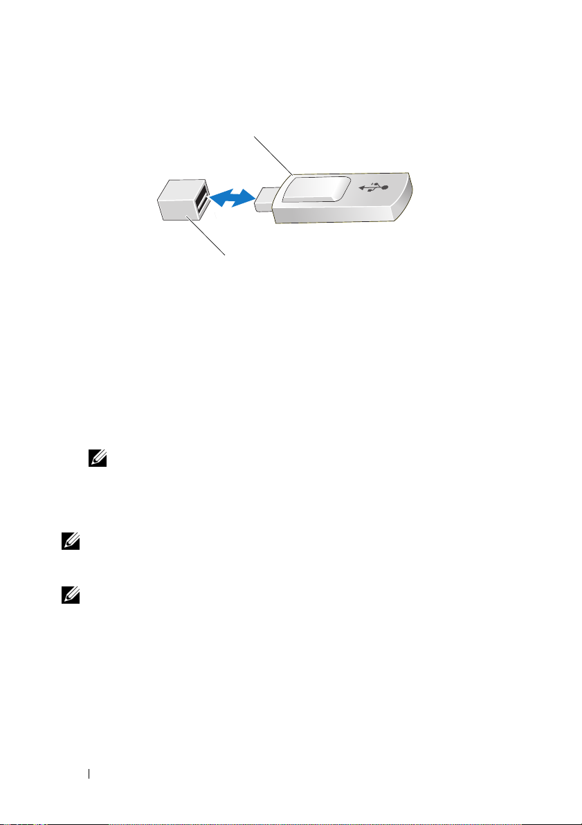
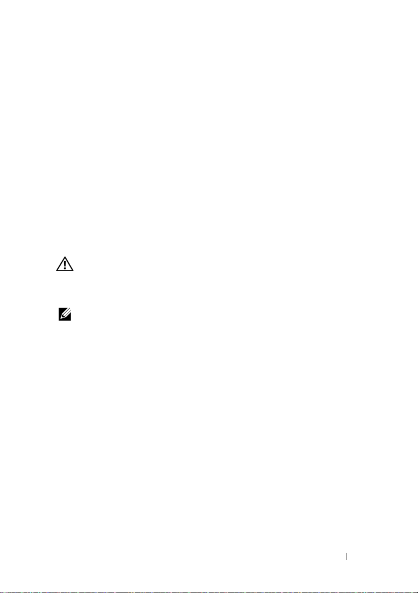
Figure 1. Removing or Installing a USB Memory Key
1
2
1 USB memory key 2 USB memory key connector
Added Support for 8-GB Memory Modules
Your Dell™ PowerEdge™ R900 system now supports the following 8-GB
memory configurations:
• 32 GB — 4 x 8-GB quad-rank memory modules
• 64 GB — 8 x 8-GB quad-rank memory modules
NOTE: If 64 GB of memory is installed, the system will only recognize
and display 63.75 GB during POST.
• 128 GB — 16 x 8-GB quad-rank memory modules
• 256 GB — 32 x 8-GB quad-rank memory modules
NOTE: Prior to upgrading your system, verify that the latest system BIOS version is
on your system. Loading the latest BIOS version from support.dell.com will ensure
that your system is fully supported.
NOTE: Some operating systems cannot support more than 4 GB of physical
memory. For more information on memory support requirements and restrictions,
refer to the operating system documentation that ships with your system.
4 Information Update
Page 5

BMC and DRAC5 Firmware Version Requirements
When upgrading either the BMC or the DRAC5, you must update the
firmware for both components to ensure full functionality and compatibility.
For example, the power reduction feature of the DRAC5 version 1.40
firmware works only when BMC 2.27 or higher is also installed. If the BMC
and DRAC firmware are incompatible—BMC 2.27 installed with DRAC5
version 1.33 or BMC 1.79 installed with DRAC5 version 1.40—the power
reduction feature may not function correctly.
Back Cooling Fans
Systems manufactured after September 2008 no longer include the four back
cooling fans installed in earlier systems. Therefore, BMC version 2.27 does
not recognize the presence of back fans. The back fans will still run in older
systems; however, from a system perspective, the fans do not exist and are
not monitored. As a result, if the back fans fail, the SEL, server management
software, and remote access card will not log the error. This change does not
compromise the standard hot plug and redundancy features of the front fans.
New LCD Error Codes
The following LCD error codes have been added for your system. For a
complete list of error codes, see "About Your System" in your Hardware
Owner’s Manual.
Table 1. LCD Status Messages
Code Test Causes Corrective Actions
EB107 Proc
Machine
Check Error
EB113 PCIE Fatal
Error
Slot XX
CPU detected an
unrecoverable hardware
error.
CPU detected an
unrecoverable hardware
error.
See error EB113 for specific
information on what
hardware failed.
"XX" indicates the slot
associated with the failed
hardware. If you are unable
to resolve the issue, see
"Getting Help" in your
Hardware Owner’s Manual.
Information Update 5
Page 6

Table 1. LCD Status Messages (continued)
Code Test Causes Corrective Actions
E1A18 PDB Ctrl
Cable
E1118 CPU Temp
Interface
E1716 Chipset
E1717 IERR
E1914 DRAC5 Conn
2 Cbl
E2122 Fatal Mem
Reset
I1915 Video Off
I1916 Video Off
in XX
PDB control cable is
missing, loose, or faulty.
Processor has exceeded
acceptable temperature
and has been disabled
to prevent damage.
The BIOS has
determined that there
is a problem with the
chipset, but is unable
to determine its origin.
CPU is faulty. Applicable
only for BIOS 1.1.9 and
BMC 2.27 and later.
DRAC5 cable is missing,
loose, or faulty.
System memory failed. See "Troubleshooting
Local video is disabled. Information only.
Remote disabling of
local video currently
in process.
Reseat the cable. If problem
persists, replace the cable.
See "Getting Help" in your
Hardware Owner’s Manual.
See "Troubleshooting
System Cooling" in your
Hardware Owner’s Manual.
See "Getting Help" in your
Hardware Owner’s Manual.
Replace the CPU.
See "Troubleshooting
Processors" in your Hardware
Owner’s Manual.
Reseat the cable. If problem
persists, replace the cable.
See "Getting Help" in your
Hardware Owner’s Manual.
System Memory" in your
Hardware Owner’s Manual.
Information only.
NOTE: For the full name of an abbreviation or acronym used in this table, see "Glossary"
in your Hardware Owner’s Manual.
6 Information Update
Page 7

New SEL Sensor Messages
The following SEL sensor messages have been added to the systems
management software and remote access card software.
Table 2. Sensor Message Definitions
Sensor Number Message Definition
0x26 PCIE Non Fatal
error
0x27 Generic Fatal
I/O Error
0x28 Processor
Machine Check
Error
NOTE: For the full name of an abbreviation or acronym used in this table, see "Glossary"
in your Hardware Owner’s Manual.
A non-fatal error occurred. The system
will continue to operate normally.
A fatal I/O error occurred. The system
will no longer respond.
A processor error occurred. The system
will no longer respond.
System Board Replacement - Safeguarding Encrypted Data
On systems using an operating system that supports the Trusted Platform
Module (TPM) and related encryption programs, you can use these features
to secure the contents of the hard drive(s).
If you are using the TPM with an encryption program, you may be prompted
to create a recovery key during system or program setup. Be sure to create and
safely store this recovery key. If you ever need to replace the system board, you
must supply the recovery key when you restart your system or program, before
you can access the encrypted data on your hard drive(s).
Information Update 7
Page 8

8 Information Update
Page 9

Dell™ PowerEdge™
R900 系统
信息更新
Page 10

注、小心和警告
注:“注”表示可以帮助您更好地使用计算机的重要信息。
小心:“小心”表示如果不遵循说明,就有可能损坏硬件或导
致数据丢失。
警告:
“警告”表示可能会造成财产损失、人身伤害甚至死亡。
____________________
本说明文件中的信息如有更改,恕不另行通知。
© 2008-2009 Dell Inc.
未经
Dell Inc.
本文中使用的商标:
本说明文件中述及的其它商标和产品名称是指拥有相应商标和产品名称的公司或其制造的
产品。
Dell Inc.
2009 年 6
月
版权所有,翻印必究。
书面许可,严禁以任何形式复制这些材料。
Dell、DELL
对本公司的商标和产品名称之外的其它商标和产品名称不拥有任何专有权。
Rev. A05
徽标和
P owerEdge 是 Dell Inc.
的商标。
Page 11
信息更新
安装内部
存储钥匙可用作引导设备、安全保护密钥或大容量存储设备。
USB
要使用内部
(集成设备)屏幕中的
要从
USB
在系统设置程序的引导顺序中指定
册》中的“集成设备屏幕”
信息,请参阅
警告: 多数维修只能由经认证的维修技术人员进行。您只能根据产品说明
文件中的授权或者在联机或电话服务和支持小组的指导下,进行故障排除和
简单的维修。
注:为了避免干扰其它组件,
(
0.94
1
关闭系统和所有连接的外围设备,并断开系统与电源插座的连接。
2
打开系统护盖。请参阅《硬件用户手册》中的“卸下和安装顶盖”。
3
在系统板上找到
4
将
USB
5
合上系统护盖。请参阅《硬件用户手册》中的“卸下和安装顶盖”。
6
将系统重新连接至电源,然后重新启动系统。
USB
USB
存储钥匙引导,必须为
USB
英寸)宽
存储钥匙插入到
存储钥匙
连接器,必须启用系统设置程序的
Internal USB Port
USB
。
有关在
存储钥匙随附的用户说明文件。
USB
x 79
USB
毫米(
连接器。请参阅《硬件用户手册》中的图
3.11
USB
英寸)长
连接器中。
(内部
USB
存储钥匙配置一个引导映像,然后
存储钥匙。请参
USB
存储钥匙上创建可引导文件的
USB
钥匙允许的最大尺寸为
毫米(
x 8.6
Integrated Devices
端口)选项。
阅
《硬件用户手
毫米
24
英寸)高。
0.33
6-1
。
信息更新 11
Page 12
图
1.
卸下或安装
USB
存储钥匙
1
2
1
添加了对
Dell™ PowerEdge™ R900
•
•
•
•
注:在升级系统之前,请验证系统上的系统
—
32 GB
—
64 GB
注:如果安装了
显示
128 GB
256 GB
从
—
—
support.dell.com
注:某些操作系统无法支持超过
制的详情,请参阅系统附带的操作系统说明文件。
存储钥匙
USB
8-GB
4 x 8-GB
8 x 8 GB
63.75 GB
16 x 8-GB
32 x 8-GB
内存模块的支持
系统目前支持下列
四排内存模块
四排内存模块
64 GB
。
四排内存模块
四排内存模块
载入最新的
2
的内存,则在
版本可以确保系统得到完全支持。
BIOS
4 GB
存储钥匙连接器
USB
内存配置:
8-GB
期间,系统只能识别并
POST
是否为最新版本。
BIOS
的物理内存。有关内存支持要求和限
12 信息更新
Page 13

BMC 和 DRAC5
升级
BMC 或 DRAC5
整功能和兼容性。
例如,
或更高版本时才起作用。如果
与
安装),则功率减少功能可能无法正常工作。
DRAC5 版本 1.40
DRAC5
版本
1.33
固件版本要求
时,必须同时为两个组件更新固件以确保其具有完
固件的功率减少功能仅在同时安装了
BMC 与 DRAC
一起安装或
BMC 1.79 与 DRAC5
背面冷却风扇
固件不兼容(如
版本
1.40
BMC 2.27
BMC 2.27
一起
2008 年 9
风扇。因此,
仍然运行背面风扇;但是,从系统的角度而言,风扇并不存在且其不受监
视。因此,如果背面风扇发生故障,则服务器管理软件
卡将不会记录错误。此更改不会危及正面风扇的标准热插拔和冗余功能。
新
已为系统添加下列
请参阅《硬件用户手册》中的“关于系统”。
表
1. LCD
代码 检测 原因 纠正措施
EB107 Proc
EB113 PCIE Fatal
E1A18 PDB Ctrl
月以后生产的系统不再包含在早期系统中安装的四个背面冷却
LCD
状态信息
Machine
Check Error
Error Slot
Cable
版本
BMC
错误代码
LCD
不能识别存在的背面风扇。较旧版本的系统
2.27
SEL
错误代码。有关错误代码的完整列表,
检测到不可恢
CPU
复的硬件错误。
检测到不可恢
CPU
复的硬件错误。
控制电缆缺失、
PDB
松开或出现故障。
请参阅错误
关于硬件故障类型的特定
信息。
“XX”指示与故障硬件关
联的插槽。如果您无法解
决此问题,请参阅 《硬件
用户手册》中的 “获得
帮助”。
请重置电缆。如果问题仍
然存在,请更换电缆。
请参阅 《硬件用户手册》
中的 “获得帮助”。
和远程访问
以获得
EB113
信息更新 13
Page 14

表
1. LCD
代码 检测 原因 纠正措施
E1118 CPU Temp
E1716 Chipset
E1717 IERR
E1914 DRAC5
E2122 Fatal Mem
I1915 Video Off
I1916 Video Off
状态信息 (续)
Interface
Conn2 Cbl
Reset
in XX
处理器超出了允许的温
度,为防止造成损坏,
已经禁用。
已确定芯片集出
BIOS
现问题,但无法确定问
题根源。
出现故障。仅适用
CPU
于
BIOS 1.1.9 和 BMC
及更高版本。
2.27
DRAC5
松开或出现故障。
系统内存出现故障。 请参阅 《硬件用户手册》
禁用了本地视频。 仅供参考。
远程禁用目前正在运
行中的本地视频。
电缆缺失、
请参阅 《硬件用户手册》
中的 “系统冷却故障
排除”。
请参阅 《硬件用户手册》
中的 “获得帮助”。
请更换
《硬件用户手册》中的
“处理器故障排除”。
请重置电缆。如果问题仍
然存在,请更换电缆。
请参阅 《硬件用户手册》
中的 “获得帮助”。
中的 “系统内存故
障排除”。
仅供参考。
CPU
。请参阅
注:有关本表中缩写词或首字母缩写词的完整名称,请参阅 《硬件用户手册》
中的 “词汇表”。
14 信息更新
Page 15

新
SEL
下列
表
2.
传感器号 信息 定义
0x26 PCIE Non Fatal
传感器信息
传感器信息已添加到系统管理软件和远程访问卡软件中。
SEL
传感器信息定义
发生非严重错误。系统将继续正
error
常运作。
0x27 Generic Fatal
I/O Error
0x28 Processor
Machine Check
Error
注:有关本表中缩写词或首字母缩写词的完整名称,请参阅 《硬件用户手册》
中的 “词汇表”。
系统板更换
如果系统使用的操作系统支持受信任的平台模块
程序,那么在系统上使用这些功能可以保护硬盘驱动器的内容安全。
如果使用的是包含加密程序的
到创建恢复密钥的提示。确保创建并安全存储此恢复密钥。如果需要更换
系统板,则必须在重新启动系统或程序时提供此恢复密钥,然后才能访问
硬盘驱动器上的加密数据。
保护加密数据
-
TPM
发生严重
发生处理器错误。系统将不再响应。
,则您会在系统或程序安装过程中收
错误。系统将不再响应。
I/O
(TPM)
和相关加密
信息更新 15
Page 16

16 信息更新
Page 17

Systèmes Dell™
PowerEdge™ R900
Mise à jour des
informations
Page 18

Remarques, précautions et avertissements
REMARQUE : Une REMARQUE indique des informations importantes qui peuvent
vous aider à mieux utiliser votre ordinateur.
PRÉCAUTION : Une PRÉCAUTION vous avertit d'un risque de dommage matériel
ou de perte de données en cas de non-respect des instructions données.
AVERTISSEMENT: Un AVERTISSEMENT vous avertit d'un risque d'endom-
magement du matériel, de blessure corporelle ou de mort.
____________________
Les informations contenues dans ce document sont sujettes à modification sans préavis.
© 2008-2009 Dell Inc. tous droits réservés.
La reproduction de ce document de quelque manière que ce soit sans l'autorisation écrite de Dell Inc.
est strictement interdite.
Marques mentionnées dans ce document : Dell, le logo DELL et PowerEdge sont des marques de Dell Inc.
D'autres marques commerciales et noms de marque peuvent être utilisés dans ce document pour faire
référence aux entités se réclamant de ces marques et de ces noms ou de leurs produits. Dell Inc. dénie
tout intérêt propriétaire vis-à-vis des marques commerciales et des noms de marque autres que les siens.
Juin 2009 Rév. A05
Page 19

Mise à jour des informations
Installation d'une clé de mémoire USB interne
La clé de mémoire USB peut servir de périphérique d'amorçage, de clé
de sécurité ou de périphérique de stockage de masse. Pour utiliser le
connecteur USB interne, vous devez activer l'option
(Port USB interne) de l'écran
du programme de configuration du système.
Pour pouvoir démarrer le système à partir de la clé de mémoire USB, vous devez
configurer celle-ci avec une image d'amorçage et la spécifier dans la séquence
d'amorçage définie dans le programme de configuration du système. Voir la
section “Écran Périphériques intégrés” du
d'informations sur la procédure de création d'un fichier d'amorçage sur la clé
de mémoire USB, voir la documentation fournie avec cette dernière.
AVERTISSEMENT: De nombreux types de réparations doivent être exclusi-
vement confiés à un technicien de maintenance qualifié. N'effectuez que les
opérations de dépannage et les petites réparations autorisées par la documentation de votre produit, ou selon les instructions fournies en ligne ou par téléphone
par l'équipe d'entretien et d'assistance technique.
REMARQUE : Pour éviter toute interférence avec d'autres composants, la clé USB
ne doit pas dépasser les dimensions suivantes : 24 mm (0,94 po) de largeur x 79 mm
(3,11 po) de longueur x 8,60 mm (0,33 po) de hauteur.
1
Éteignez le système et les périphériques connectés, puis débranchez
le système de la prise secteur.
2
Ouvrez le système. Voir la section “Retrait et installation du panneau
supérieur” du
3
Identifiez le connecteur USB sur la carte système. Voir la figure 6-1
du
Manuel du propriétaire
4
Insérez la clé de mémoire USB dans le connecteur.
5
Refermez le système. Voir la section “Retrait et installation du panneau
supérieur” du
6
Rebranchez le système sur l'alimentation, puis redémarrez-le.
Manuel du propriétaire
Manuel du propriétaire
Integrated Devices
Manuel du propriétaire
.
.
.
Internal USB Port
(Périphériques intégrés)
. Pour plus
Mise à jour des informations 19
Page 20

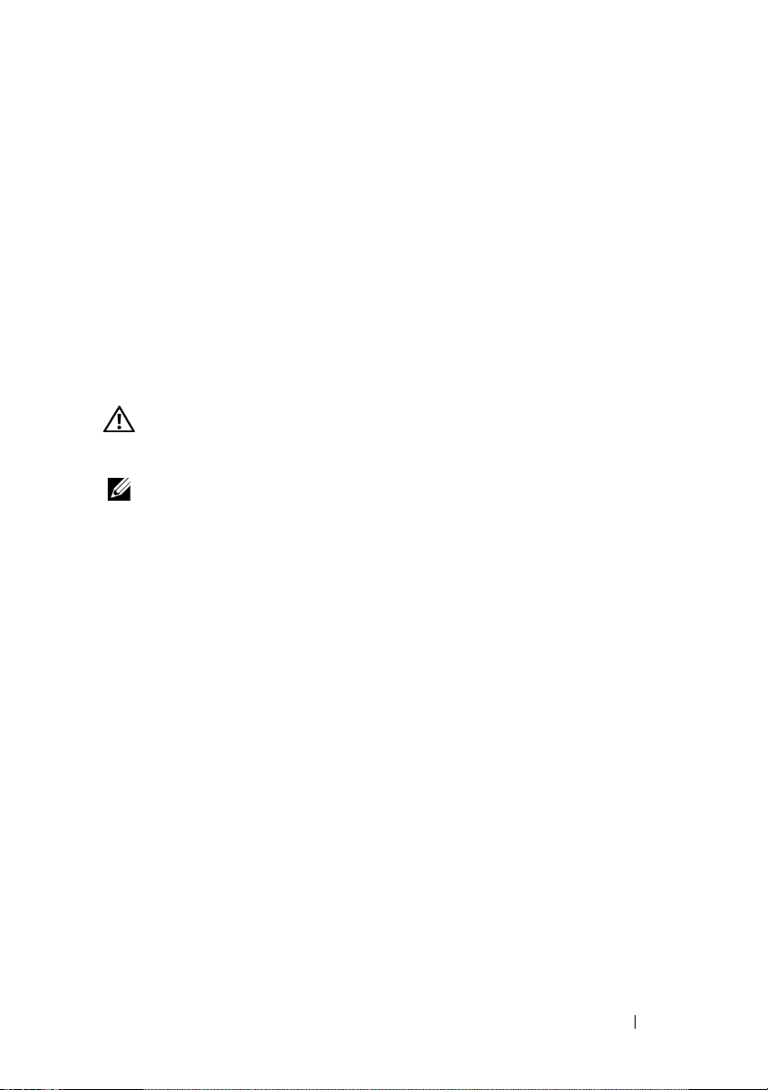
Figure 1. Retrait ou installation d'une clé de mémoire USB
1
2
1 clé de mémoire USB 2 connecteur de clé de mémoire USB
Prise en charge supplémentaire pour les barrettes de mémoire 8 Go
Le système Dell™ PowerEdge™ R900 prend désormais en charge les configurations de mémoire 8 Go suivantes :
• 32 Go : 4 barrettes de mémoire à quadruple rangée de connexions de 8 Go
• 64 Go : 8 barrettes de mémoire à quadruple rangée de connexions de 8 Go
REMARQUE : Si la capacité de mémoire installée est de 64 Go, le système
ne reconnaîtra et n'affichera que 63,75 Go pendant l'autotest de démarrage.
• 128 Go : 16 barrettes de mémoire à quadruple rangée de connexions
de 8 Go
• 256 Go : 32 barrettes de mémoire à quadruple rangée de connexion 8 Go
REMARQUE : Avant de procéder à une mise à niveau du système, vérifiez que la
version la plus récente du BIOS du système est installée. Vous pouvez la charger
depuis le site support.dell.com. Vous pourrez ainsi vous assurer que votre système
est totalement pris en charge.
REMARQUE : Certains systèmes d'exploitation ne peuvent pas prendre en charge
plus de 4 Go de mémoire physique. Pour plus d'informations sur la configuration
requise et les restrictions concernant la mémoire, voir la documentation du système
d'exploitation fournie avec votre système.
20 Mise à jour des informations
Page 21

Versions des micrologiciels BMC et DRAC5 requises
Si vous mettez à niveau le micrologiciel BMC ou DRAC5, vous devez effectuer
deux
cette procédure pour les
opérationnels et compatibles.
Par exemple, l'option de réduction de l'alimentation de la version DRAC5,
micrologiciel 1.40 ne fonctionne que si la version BMC 2.27 ou supérieure est
également installée. En cas d'incompatibilité des micrologiciels BMC et DRAC
(par exemple si BMC version 2.27 est installé parallèlement à DRAC5
version 1.33 ou si BMC version 1.79 est installé parallèlement à DRAC5
version 1.40), la réduction de l'alimentation risque de ne pas fonctionner
correctement.
composants afin que ceux-ci soient entièrement
Ventilateurs arrière
Les systèmes fabriqués après septembre 2008 ne sont plus équipés des
quatre ventilateurs arrière que comportaient les systèmes précédents. C'est
pourquoi BMC version 2.27 ne reconnaît pas la présence des ventilateurs arrière.
Ces ventilateurs fonctionnent sur les systèmes antérieurs, bien qu'ils ne soient
ni reconnus, ni contrôlés par le système. En conséquence, si les ventilateurs
tombent en panne, aucune erreur n'est consignée dans le journal d'événements
du système (SEL) ni par le logiciel de gestion du serveur ou la carte d'accès
à distance. Cette modification n'altère en rien les fonctionnalités standard
d'enfichage à chaud et de redondance des ventilateurs avant.
Mise à jour des informations 21
Page 22

Nouveaux codes d'erreur affichés sur l'écran LCD
Les codes d'erreur suivants ont été ajoutés. Pour obtenir la liste complète des
codes d'erreur, voir la section “À propos du système” du
Tableau 1. Messages d'état affichés sur l'écran LCD
Code Test Causes Actions correctives
EB107 Proc
Machine
Check Error
EB113 PCIE Fatal
Error Slot
XX
E1A18 PDB Ctrl
Cable
E1118 CPU Temp
Interface
E1716 Chipset
Le processeur a détecté
une erreur matérielle
irrécupérable.
Le processeur a détecté
une erreur matérielle
irrécupérable.
Le câble de contrôle PDB
est manquant, mal
installé ou défaillant.
Le processeur a atteint la
température limite et a
été désactivé pour éviter
tout risque
d'endommagement.
Le BIOS a détecté un
problème au niveau du
circuit microprogrammé,
mais n'est pas en mesure
d'en déterminer l'origine.
Manuel du propriétaire
Voir l'erreur EB113 pour
obtenir des informations
spécifiques sur le composant
défaillant.
“XX” indique l'emplacement
associé au composant
défaillant. Si vous ne parvenez pas à résoudre le problème, voir la section
“Obtention d'aide” du
Manuel du propriétaire
Rebranchez le câble dans le
connecteur. Si le problème
persiste, remplacez le câble.
Voir la section “Obtention
d'aide” du
propriétaire
Voir la section “Dépannage
du refroidissement du
système” du
propriétaire.
Voir la section “Obtention
d'aide” du
propriétaire
Manuel du
.
Manuel du
Manuel du
.
.
.
22 Mise à jour des informations
Page 23

Tableau 1. Messages d'état affichés sur l'écran LCD (suite)
Code Test Causes Actions correctives
E1717 IERR
E1914 DRAC5
Conn 2 Cbl
E2122 Fatal Mem
Reset
I1915 Video Off
I1916 Video Off
in XX
Le processeur est
défaillant. Applicable
uniquement au BIOS
version 1.1.9 et au
BMC 2.27 et version
ultérieure.
Le câble DRAC5 est
manquant, mal installé
ou défaillant.
La mémoire système
est défaillante.
La vidéo locale est
désactivée.
La vidéo locale est en
cours de désactivation
àdistance.
Remplacez le processeur.
Voir la section “Dépannage
des processeurs” du
du propriétaire
Rebranchez le câble dans le
connecteur. Si le problème
persiste, remplacez le câble.
Voir la section “Obtention
d'aide” du
propriétaire
Voir la section “Dépannage
de la mémoire système”
Manuel du propriétaire.
du
Pour information
uniquement.
Pour information
uniquement.
.
Manuel du
.
REMARQUE : Pour obtenir le nom complet d'une abréviation ou d'un sigle utilisé
dans ce tableau, voir la section “Glossaire” du Manuel du propriétaire.
Manuel
Mise à jour des informations 23
Page 24

Nouveaux messages de capteur du journal des événements du système (SEL)
Les messages de capteur du journal des événements du système suivants ont été
ajoutés au logiciel Systems Management Software et à celui de la carte d'accès
à distance.
Tableau 2. Définition du message de capteur
Numéro
du capteur
0x26 PCIE Non
0x27 Generic Fatal
0x28 Processor
REMARQUE : Pour obtenir le nom complet d'une abréviation ou d'un sigle utilisé
dans ce tableau, voir la section “Glossaire” du Manuel du propriétaire.
Message Définition
Une erreur non fatale s'est produite.
Fatal error
I/O Error
Machine Check
Error
Le système continuera à fonctionner
normalement.
Une erreur fatale d'E/S s'est produite.
Le système ne pourra plus répondre.
Une erreur s'est produite au niveau du
processeur. Le système ne pourra plus
répondre.
Remplacement de la carte système - Protection des données cryptées
Sur les systèmes équipés d'un système d'exploitation prenant en charge la
puce TPM (Trusted Platform Module) et les programmes de cryptage associés,
vous pouvez utiliser ces fonctionnalités pour protéger le contenu du ou des
lecteurs de disque dur.
Si vous utilisez la puce TPM avec un programme de cryptage, vous pouvez être
invité à créer une clé de récupération lors de la configuration du système ou du
programme. Vous devez créer cette clé et la conserver en lieu sûr. Si vous êtes
amené à remplacer la carte système, vous devrez fournir cette clé lors du
redémarrage du système ou du programme pour accéder aux données cryptées
qui se trouvent sur le ou les lecteurs de disque dur.
24 Mise à jour des informations
Page 25

Dell™ PowerEdge™ R900
Systeme
Aktuelle Informationen
Page 26

Anmerkungen, Vorsichtshinweise
und Warnungen
ANMERKUNG: Eine ANMERKUNG macht auf wichtige Informationen
aufmerksam, mit denen Sie das System besser einsetzen können.
VORSICHTSHINWEIS: Hiermit werden Sie auf mögliche Gefahrenquellen
hingewiesen, die Hardwareschäden oder Datenverlust zur Folge haben können,
wenn die Anweisungen nicht befolgt werden.
WARNUNG: Durch eine WARNUNG werden Sie auf Gefahrenquellen
hingewiesen, die materielle Schäden, Verletzungen oder sogar den Tod
von Personen zur Folge haben können.
____________________
Irrtümer und technische Änderungen vorbehalten.
© 2008–2009 Dell Inc. Alle Rechte vorbehalten.
Die Vervielfältigung oder Wiedergabe dieser Materialien, in jeglicher Weise ohne vorherige
schriftliche Genehmigung von Dell Inc. ist strengstens untersagt.
In diesem Text verwendete Marken: Dell, das DELL Logo und PowerEdge sind Marken von Dell Inc.
Alle anderen in dieser Dokumentation genannten Marken und Handelsbezeichnungen sind Eigentum
der entsprechenden Hersteller und Firmen. Dell Inc. erhebt keinen Anspruch auf Markenzeichen und
Handelsbezeichnungen mit Ausnahme der eigenen.
Juni 2009 Rev. A05
Page 27

Aktuelle Informationen
Installation eines internen USB-Sticks
Der USB-Speicherstick lässt sich als Startgerät, Sicherheitsschlüssel oder
Massenspeichergerät einsetzen. Um den internen USB-Anschluss zu
verwenden, muss die Option
Bildschirm
Programms aktiviert sein.
Um vom USB-Speicherstick zu starten, müssen Sie den USB-Speicherstick
mit einem Boot-Image konfigurieren und den USB-Speicherstick in der Startreihenfolge des System-Setup-Programms spezifizieren. Siehe den Abschnitt
zum Bildschirm „Integrierte Geräte“ im
mationen zum Erstellen einer startfähigen Datei auf dem USB-Speicherstick
finden Sie in der zugehörigen Dokumentation.
1
2
3
4
5
6
Integrated Devices
WARNUNG: Viele Reparaturarbeiten dürfen nur von qualifizierten Service-
technikern durchgeführt werden. Fehlerbehebungsmaßnahmen oder einfache
Reparaturen sollten Sie nur dann selbst übernehmen, wenn dies in der Produktdokumentation ausdrücklich vorgesehen ist oder Sie vom Team des Online- oder
Telefonsupports dazu aufgefordert werden.
ANMERKUNG: Um nicht mit anderen Komponenten in Konflikt zu geraten,
betragen die maximal zulässigen Abmessungen des USB-Sticks
24 mm Breite x 79 mm Länge x 8,6 mm Höhe.
Schalten Sie das System und die Peripheriegeräte aus und trennen Sie
das System vom Netzstrom.
Öffnen Sie das System. Siehe „Entfernen/Anbringen der oberen
Abdeckung“ im
Lokalisieren Sie den Anschluss USB auf der Systemplatine.
Siehe Abbildung 6-1 im
Setzen Sie den USB-Speicherstick in den USB-Anschluss ein.
Schließen Sie das System. Siehe „Entfernen/Anbringen der oberen
Abdeckung“ im
Verbinden Sie das System mit dem Netzstrom und starten Sie
das System neu.
Hardware-Benutzerhandbuch
Hardware-Benutzerhandbuch
Internal USB Port
(Integrierte Geräte) des System-Setup-
Hardware-Benutzerhandbuch
(Interner USB-Port) im
Hardware-Benutzerhandbuch
.
.
.
. Infor-
Aktuelle Informationen 27
Page 28

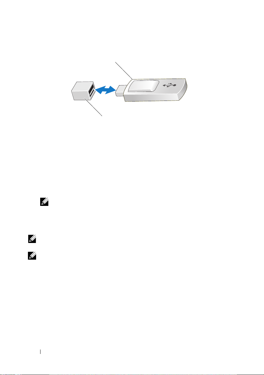
Abbildung 1. USB-Speicherstick entfernen oder installieren
1
2
1 USB-Speicherstick 2 Anschluss für USB-Speicherstick
Unterstützung von 8-GB-Speichermodulen
Das Dell™ PowerEdge™ R900 System unterstützt jetzt die folgenden 8-GBSpeicherkonfigurationen:
• 32 GB — 4 x 8-GB Vierfach-Speichermodule
• 64 GB — 8 x 8-GB Vierfach-Speichermodule
ANMERKUNG: Wenn 64 GB Speicher installiert sind, erkennt das System
beim POST nur 63,75 GB und zeigt diese an.
• 128 GB — 16 x 8-GB Vierfach-Speichermodule
• 256 GB — 32 x 8-GB Vierfach-Speichermodule
ANMERKUNG: Überprüfen Sie vor dem Upgrade des Systems, ob die aktuelle
BIOS-Version auf dem System installiert ist. Laden Sie die neueste BIOS-Version
von support.dell.com herunter, um sicherzustellen, dass Ihr System vollständig
unterstützt wird.
ANMERKUNG: Einige Betriebssysteme unterstützen nicht mehr als 4 GB
physischen Speicher. Weitere Informationen zu den Anforderungen und
Einschränkungen der Speicherunterstützung finden Sie in der Dokumentation
zum Betriebssystem, das Sie mit dem System erhalten haben.
28 Aktuelle Informationen
Page 29

Firmware-Mindestversionen für BMC und DRAC5
Beim Aktualisieren des BMC oder des DRAC5 müssen Sie die Firmware
beide
für
und Kompatibilität sicherzustellen.
Die Energiesparfunktion der DRAC5-Firmware Version 1.40 funktioniert zum
Beispiel nur, wenn auch BMC 2.27 oder höher installiert ist. Wenn die Firmware
für den BMC und den DRAC nicht kompatibel ist – BMC 2.27 mit DRAC5
Version 1.33 oder BMC 1.79 mit DRAC5 Version 1.40 – funktioniert die
Energiesparfunktion nicht ordnungsgemäß.
Komponenten aktualisieren, um die vollständige Funktionalität
Lüfter auf der Rückseite
Systeme, die nach September 2008 hergestellt wurden, verfügen nicht über die
vier rückwärtigen Lüfter, die in älteren Systemen eingebaut waren. Der BMC
Version 2.27 erkennt das Vorhandensein von Lüftern auf der Rückseite deshalb
nicht. Die in älteren Systemen vorhandenen Lüfter auf der Rückseite
funktionieren nach wie vor; das System betrachtet sie jedoch als nicht
vorhanden und die Lüfter werden nicht überwacht. Wenn die Lüfter auf der
Rückseite ausfallen, wird dieser Fehler vom Systemereignisprotokoll, von der
Serververwaltungssoftware und der Remote-Access-Karte nicht protokolliert.
Diese Änderung beeinträchtigt nicht die standardmäßigen Hot-Plug- und
Redundanzfunktionen der vorderen Lüfter.
Aktuelle Informationen 29
Page 30

Neue LCD-Fehlercodes
Es gibt die folgenden neuen LCD-Fehlercodes für das System. Eine vollständige
Liste der Fehlercodes finden Sie unter „Wissenswertes zum System“ im
Hardware-Benutzerhandbuch
Tabelle 1. Meldungen der LCD-Statusanzeige
Code Test Ursachen Korrekturmaßnahmen
EB107 Proc
Machine
Check Error
EB113 PCIE Fatal
Error Slot
XX
E1A18 PDB Ctrl
Cable
E1118 CPU Temp
Interface
E1716 Chipset
.
Die CPU hat einen nicht
behebbaren Hardwarefehler festgestellt.
Die CPU hat einen nicht
behebbaren Hardwarefehler festgestellt.
Das PDB-Steuerkabel
ist nicht vorhanden,
lose oder fehlerhaft.
Der Prozessor hat den
zulässigen Temperaturbereich überschritten
und wurde deaktiviert,
um Beschädigung zu
verhindern.
Das BIOS hat ein
Problem mit dem
Chipsatz festgestellt,
kann die Ursache aber
nicht erkennen.
Siehe Fehler EB113 zu
spezifischen Informationen
zur betroffenen Hardware.
„XX“ gibt den zur
ausgefallenen Hardware
zugehörigen Anschluss an.
Wenn Sie das Problem nicht
lösen können, lesen Sie „Wie
Sie Hilfe bekommen“ im
Hardware-Benutzerhandbuch
Befestigen Sie das Kabel.
Falls das Problem weiterhin
besteht, tauschen Sie das
Kabel aus. Lesen Sie den
Abschnitt „Wie Sie Hilfe
bekommen“ im
Benutzerhandbuch
Siehe „Fehlerbehebung bei
der Systemkühlung“ im
Hardware-Benutzerhandbuch.
Lesen Sie den Abschnitt
„Wie Sie Hilfe bekommen“
Hardware-Benutzer-
im
handbuch
Hardware-
.
.
.
30 Aktuelle Informationen
Page 31

Tabelle 1. Meldungen der LCD-Statusanzeige (Fortgesetzt)
Code Test Ursachen Korrekturmaßnahmen
E1717 IERR
E1914 DRAC5 Conn
2 Cbl
E2122 Fatal Mem
Reset
I1915 Video Off
I1916 Video Off
in XX
CPU ist fehlerhaft. Gilt
nur für BIOS 1.1.9 und
BMC 2.27 oder höher.
Das DRAC5-Kabel ist
nicht vorhanden, lose
oder fehlerhaft.
Fehler beim
Systemspeicher.
Lokaler Videoanschluss
ist deaktiviert.
Lokaler Videoanschluss
wird zurzeit remote
deaktiviert.
Ersetzen Sie die CPU.
Siehe „Fehlerbehebung bei
Prozessoren im
Benutzerhandbuch
Befestigen Sie das Kabel.
Falls das Problem weiterhin
besteht, tauschen Sie das
Kabel aus. Lesen Sie den
Abschnitt „Wie Sie Hilfe
bekommen“ im
Benutzerhandbuch
Siehe „Fehlerbehebung
beim Systemspeicher“ im
Hardware-Benutzerhandbuch.
Dient nur zur Information.
Dient nur zur Information.
Hardware-
.
Hardware-
.
ANMERKUNG: Eine Beschreibung der Abkürzungen und Akronyme finden Sie
im Glossar des Hardware-Benutzerhandbuchs.
Aktuelle Informationen 31
Page 32

Neue SEL-Sensormeldungen
Die folgenden SEL-Sensormeldungen wurden der Systemverwaltungssoftware
und der Remote-Access-Kartensoftware hinzugefügt.
Tabelle 2. Definitionen der Sensormeldungen
Sensornummer Meldung Definition
0x26 PCIE Non Fatal
error
0x27 Generic Fatal
I/O Error
0x28 Processor
Machine Check
Error
ANMERKUNG: Eine Beschreibung der Abkürzungen und Akronyme finden Sie
im Glossar des Hardware-Benutzerhandbuchs.
Ein nicht schwerwiegender Fehler ist
aufgetreten. Der normale Betrieb des
Systems wird fortgesetzt.
Ein schwerwiegender E/A-Fehler ist
aufgetreten. Das System reagiert nicht
mehr.
Ein Prozessorfehler ist aufgetreten.
Das System reagiert nicht mehr.
Systemplatinenaustausch - Schutz verschlüsselter Daten
Auf Systemen mit einem Betriebssystem, das das Trusted Platform Module
(TPM) und verwandte Verschlüsselungsprogramme unterstützt, können Sie
mit diesen Funktionen den Inhalt der Festplattenlaufwerke schützen.
Wenn Sie das TPM mit einem Verschlüsselungsprogramm verwenden, werden
Sie möglicherweise aufgefordert, während des System- oder Programm-Setups
einen Wiederherstellungsschlüssel zu erstellen. Diesen Wiederherstellungsschlüssel sollten Sie unbedingt erstellen und sicher speichern. Sollte es einmal
erforderlich sein, die Systemplatine zu ersetzen, müssen Sie den Wiederherstellungsschlüssel zum Neustarten des Systems oder Programms angeben,
bevor Sie auf die verschlüsselten Daten auf den Festplattenlaufwerken zugreifen
können.
32 Aktuelle Informationen
Page 33

Dell™ PowerEdge™
R900 システム
アップデート情報
Page 34

メモ、注意、警告
メモ: コンピュータを使いやすくするための重要な情報を説明
しています。
注意 : 手順に従わない場合は、ハードウェアの損傷やデータの損失
の可能性があることを示しています。
警告: 物的損害、けが、または死亡の原因となる可能性があること
を示しています。
____________________
本書の内容は予告なく変更されることがあります。
© 2008-2009 すべての著作権は Dell Inc. にあります。
Dell Inc.
おいても厳重に禁じられています。
本書に使用されている商標:
商標または製品の権利を主張する事業体を表すためにその他の商標および社名が使用されて
いることがあります。
2009 年 6 月 Rev. A05
の書面による許可を得ずにこれらのマテリアルを複製することは、いかなる形態に
Dell、DELL ロゴ、および
Dell Inc.
はデル以外の商標や社名に対する所有権を一切否認します。
PowerEdge は Dell Inc.
の商標です。
Page 35

アップデート情報
内蔵 USB メモリキーの取り付け
USB
メモリキーは、起動デバイス、セキュリティキー、または大容量スト
レージデバイスとして使用できます。内部
セットアップユーティリティの
面で
Internal USB Port
があります。
USB
メモリキーから起動するには、起動イメージを使用して
キーを設定し、セットアップユーティリティの起動順序で
キーを指定する必要があります。『ハードウェアオーナーズマニュアル』
の「
Integrated Devices
USB
メモリキー上に起動可能ファイルを作成する方法については、
USB
メモリキーに付属のユーザーマニュアルを参照してください。
警告: 修理作業の多くは、認定されたサービス技術者のみが行うことが
できます。お客様は、製品マニュアルで許可されている範囲に限り、また
はオンラインサービスもしくはテレホンサービスおよびサポートチームの
指示によってのみ、トラブルシューティングと簡単な修理を行うことがで
きます。
メモ: 他のコンポーネントとの干渉を避けるために、USB キーの最大サ
イズは横幅 24 mm x 奥行き 79 mm x 縦幅 8.6 mm までに制限されます。
1
システムおよび接続されているすべての周辺機器の電源を切り、
電源コンセントから外します。
2
システムカバーを開きます。『ハードウェアオーナーズマニュアル』
の「上部カバーの取り外しと取り付け」を参照してください。
3
システム基板上の
アオーナーズマニュアル』の図
4
USB
コネクタに
5
システムカバーを閉じます。『ハードウェアオーナーズマニュアル』
の「上部カバーの取り外しと取り付け」を参照してください。
6
システムを電源に接続し、システムの電源を入れます。
(内部
(内蔵デバイス)画面」を参照してください。
USB
USB
Integrated Devices
USB
コネクタの位置を確認します。『ハードウェ
メモリキーを挿入します。
USB
コネクタを使用するには、
(内蔵デバイス)画
ポート)オプションを有効にする必要
USB
メモリ
USB
メモリ
6-1
を参照してください。
アップデート情報 35
Page 36

図 1USB メモリキーの取り外しまたは取り付け
1
2
1
USB メモリキー
2
USB メモリキーコネクタ
8 GB のメモリモジュールが使用可能に
Dell™ PowerEdge™ R900
用した次のメモリ構成がサポートされるようになりました。
•
32 GB — 8 GB
•
64 GB — 8 GB
メモ: 64 GB のメモリが取り付けられている場合、POST 中に認識さ
れて表示されるのは 63.75 GB のみです。
•
128 GB — 8 GB
•
256 GB — 8 GB
メモ: システムをアップグレードする前に、お使いのシステムにインス
トールされているシステム BIOS が最新バージョンであることを確認して
ください。support.dell.com から BIOS の最新バージョンを入手してインス
トールすれば、お使いのシステムは完全にサポートされます。
メモ: 一部の OS は、4 GB を超える物理メモリをサポートしていません。
サポートされるメモリの要件と制限事項の詳細については、システムに付
属の OS のマニュアルを参照してください。
クアッドランクのメモリモジュール
クアッドランクのメモリモジュール
システムでは、
8 GB
のメモリモジュールを使
4
8
クアッドランクのメモリモジュール
クアッドランクのメモリモジュール
枚
枚
16
32
枚
枚
36 アップデート情報
Page 37

BMC および DRAC5 のファームウェアのバー ジョン要件
BMC
または
DRAC5
て確保するために、両方のコンポーネントのファームウェアをアップデー
トする必要があります
たとえば、
2.27
BMC 2.27 と DRAC5
ジョン
DRAC
それがあります。
DRAC5
以降も併せてインストールしてある場合にのみ正常に働きます。
1.40
などの組み合わせでインストールされているために、
のファームウェアが適合しない場合、節電機能が正常に働かないお
をアップグレードする際には、機能と互換性をすべ
。
バージョン
バージョン
1.40
ファームウェアの節電機能は、
1.33
、または
BMC 1.79 と DRAC5
BMC
バー
BMC と
背面冷却ファン
2008 年 9
付けられていた
バージョン
ステムでも動作しますが、システムはファンを認識せず、したがって監視
も行いません。そのため、背面ファンが故障しても、
ソフトウェア、およびリモートアクセスカードにエラーが記録されませ
ん。ただし、前面ファンに標準装備されているホットプラグ機能と冗長機
能には何ら影響せず、正常に動作します。
月以降に製造されたシステムには、それまでのシステムに取り
4
台の背面冷却ファンがありません。したがって、
2.27
は背面ファンの存在を認識しません。背面ファンは旧シ
SEL
、サーバー管理
BMC
アップデート情報 37
Page 38

新しい LCD エラーコード
お使いのシステムには、以下の
LCD
エラーコードが追加されています。
エラーコードの詳細なリストは、『ハードウェアオーナーズマニュアル』
の「システムについて」を参照してください。
表 1LCD ステータスメッセージ
コード テスト 原因 対応処置
EB107 Proc
Machine
Check
Error
EB113 PCIE Fatal
Error
Slot XX
E1A18 PDB Ctrl
Cable
E1118 CPU Temp
Interface
E1716 Chipset
回復不能なハードウェ
アエラーが CPU に
よって検知され
ました。
回復不能なハードウェ
アエラーが CPU に
よって検知されまし
た。
PDB コントロールケー
ブルがないか、接続に
緩みがあるか、または
不良です。
プロセッサの温度が許
容範囲を超えたため、
損傷を防ぐために無効
にされました。
BIOS によってチップ
セットに問題があるこ
とが検知されました
が、原因は特定でき
ませんでした。
どのハードウェアが故障
したかについての具体的
な情報は、エラー EB113
を参照してください。
「XX」は、故障したハード
ウェアに関連するスロッ
トを示します。問題を解
決できない場合は、『ハー
ドウェアオーナーズマ
ニュアル』の「困ったと
きは」を参照してくだ
さい。
ケーブルを抜き差ししま
す。問題が解決しない場
合は、ケーブルを交換し
ます。『ハードウェアオー
ナーズマニュアル』の
「困ったときは」を参照し
てください。
『ハードウェアオーナーズ
マニュアル』の「システ
ム冷却問題のトラブル
シューティング」を参照
してください。
『ハードウェアオーナーズ
マニュアル』の「困った
ときは」を参照してくだ
さい。
38 アップデート情報
Page 39

表 1LCD ステータスメッセージ (続き)
コード テスト 原因 対応処置
E1717 IERR
E1914 DRAC5
Conn 2 Cbl
E2122 Fatal Mem
Reset
I1915 Video Off
I1916 Video Off
in XX
CPU が不良です。
BIOS 1.1.9 および
BMC 2.27 以降にのみ
適用されます。
DRAC5 ケーブルがな
いか、接続に緩みが
あるか、または不良
です。
システムメモリが不
良です。
ローカルビデオが無効
にされています。
ローカルビデオをリ
モートから無効にす
るプロセスが進行中
です。
CPU を交換します。『ハー
ドウェアオーナーズマ
ニュアル』の「プロセッ
サのトラブルシューティ
ング」を参照してくだ
さい。
ケーブルを抜き差しし
ます。問題が解決しない
場合は、ケーブルを交換
します。『ハードウェア
オーナーズマニュアル』
の「困ったときは」を参
照してください。
『ハードウェアオーナーズ
マニュアル』の「システ
ムメモリのトラブル
シューティング」を参照
してください。
情報表示のみです。
情報表示のみです。
メモ: この表で使用されている略語や頭字語の正式名称については、『ハード
ウェアオーナーズマニュアル』の「用語集」を参照してください。
アップデート情報 39
Page 40

SEL センサーの新しいメッセージ
システム管理ソフトウェアとリモートアクセスカードソフトウェアに以下
SEL
の
表 2 センサーメッセージの定義
センサーメッセージが追加されました。
センサー番号 メッセージ 定義
0x26 PCIE Non
Fatal error
致命的ではないエラーが発生しました。
システムは引き続き正常に動作します。
0x27 Generic Fatal
I/O Error
0x28 Processor
Machine
Check Error
メモ: この表で使用されている略語や頭字語の正式名称については、『ハード
ウェアオーナーズマニュアル』の「用語集」を参照してください。
致命的な I/O エラーが発生しました。
システムはもはや応答しません。
プロセッサエラーが発生しました。
システムはもはや応答しません。
システム基板の交換 - 暗号化されたデー タの保護
Trusted Platform Module(TPM:
および関連する暗号化プログラムをサポートする
ステムでは、これらの機能を使用してハードドライブの内容を保護するこ
とができます。
暗号化プログラムと共に
ログラムのセットアップ中にリカバリキーの作成を求められることがあり
ます。このリカバリキーは必ず作成し、安全に保管しておいてください。
システム基板の交換が万一必要になった場合に、システムまたはプログラ
ムの再起動時にリカバリキーを入力しないと、ハードドライブ上の暗号化
されたデータにアクセスできません。
TPM
信頼済みプラットフォームモジュール)
OS
が使用されているシ
を使用している場合は、システムまたはプ
40 アップデート情報
Page 41

Dell™ PowerEdge™
R900 시스템
정보 갱신본
Page 42

주 , 주의 및 경고
주: "주"는 컴퓨터를 보다 효율적으로 사용하는 데 도움을 주는 중요 정보를 제
공합니다.
주의: "주의"는 지침을 준수하지 않을 경우의 하드웨어 손상이나 데이터 손실
위험을 설명합니다.
경고 : 경고는 재산상의 피해나 심각한 부상 또는 사망을 유발할 수 있는 위험
이 있음을 알려줍니다 .
____________________
이 문서의 정보는 사전 통보 없이 변경될 수 있습니다.
© 2008-2009 Dell Inc. 저작권 본사 소유.
Dell Inc.의 서면 승인 없이 어떠한 방식으로든 본 자료를 무단 복제하는 행위는 엄격히 금지됩
니다.
본 설명서에 사용된 상표인 Dell, DELL 로고 및 PowerEdge 는 Dell Inc.의 상표입니다.
본 문서에서 특정 회사의 표시나 제품 이름을 지칭하기 위해 기타 상표나 상호를 사용할 수도
있습니다
유권도 없습니다.
2009 년 6 월 Rev. A05
. Dell Inc.는 자사가 소유하고 있는 것 이외에 기타 모든 상표 및 상호에 대한 어떠한 소
Page 43

정보 갱신본
내부 USB 메모리 키 설치
USB
메모리 키는 부팅 장치, 보안 키 또는 대용량 저장 장치로 사용할 수 있
습니다
.
내부
USB
커넥터를 사용하려면 Internal USB Port(내부
옵션이 시스템 설치 프로그램의 Integrated Devices(내장형 장치) 화면에서
활성화되어 있어야 합니다
USB
메모리 키에서 부팅하려면 부팅 이미지로
다음 시스템 설치 프로그램의 부팅 순서에서
니다
.
하드웨어 소유자 매뉴얼의 "내장형 장치 화면"을 참조하십시오
메모리 키에서 부팅 파일을 작성하는 방법에 대한 내용은
함께 제공된 사용 설명서를 참조하십시오
경고 : 대부분의 수리 작업은 공인된 서비스 기술자만 수행할 수 있습니다 .
사용자는 제품 설명서에서 허가한 경우나 온라인 또는 전화서비스 / 지원팀에
서 지시한 경우에만 문제 해결 절차 및 단순 수리 작업을 수행할 수 있습니다 .
주: 다른 구성요소의 방해를 피하기 위한 USB 키의 최대 허용 크기는 폭
24mm(0.94인치) x 길이 79mm(3.11인치) x 높이 8.6mm(0.33인치)입니다.
1
시스템과 시스템에 장착된 모든 주변 장치의 전원을 끄고 전원 콘센트
에서
시스템을 분리합니다
2
시스템을 엽니다. 하드웨어 소유자 매뉴얼의 "상단 덮개 분리 및 설치
를 참조하십시오
3
시스템 보드에서
그림
6-1을
참조하십시오
4
USB
커넥터에
5
시스템을 닫습니다. 하드웨어 소유자 매뉴얼의 "상단 덮개 분리 및 설치
를 참조하십시오
6
시스템을 전원에 다시 연결하고 시스템을 재시작합니다
USB
.
USB
메모리 키를 구성한
USB
메모리 키를 지정해야 합
.
.
.
USB
커넥터를 찾습니다. 하드웨어 소유자 매뉴얼의
.
메모리 키를 삽입합니다
.
.
USB
.
USB 포트)
. USB
메모리 키와
"
"
정보 갱신본 43
Page 44

그림 1. USB 메모리 키 분리 또는 설치
1
2
1
USB 메모리 키
2
USB 메모리 키 커넥터
8GB 메모리 모듈에 대한 추가 지원
Dell™ PowerEdge™ R900
니다
.
• 32GB — 4 x 8GB 4
• 64GB — 8 x 8GB 4중
주: 64GB의 메모리가 설치되어 있을 경우 시스템에서는 POST 도중
63.75GB만 인식하여 표시합니다.
• 128GB — 16 x 8GB 4중
• 256GB — 32 x 8GB 4중
주: 시스템을 업그레이드하기 전에 시스템의 BIOS가 최신 버전인지 확인하십
시오. Dell 지원 웹 사이트(support.dell.com)에서 최신 BIOS 버전을 로드하면 시
스템이 완벽하게 지원됩니다.
주: 일부 운영 체제는 4GB 이상의 실제 메모리를 지원하지 못합니다. 메모리
지원 요구 사항 및 제한 사항에 대한 자세한 내용은 시스템과 함께 제공되는
운영 체제 설명서를 참조하십시오.
시스템은 다음과 같은
중 등급 메모리 모듈
등급 메모리 모듈
등급 메모리 모듈
등급 메모리 모듈
8GB
메모리 구성을 지원합
44 정보 갱신본
Page 45

BMC 및 DRAC5 펌웨어 버전 요구 사항
BMC 또는 DRAC5를
업데이트하여 모든 기능 및 호환성을 보장해야 합니다
예를 들어
께
되거나
어가
니다
DRAC5
설치된 경우에만 작동합니다
BMC 1.79가 DRAC5 버전 1.40과 함께
호환되지 않는 경우 전원 절약 기능이 제대로 작동하지 않을 수 있습
.
업그레이드할 때는 두 구성요소 모두에 대한 펌웨어를
.
버전
1.40
펌웨어의 전원 절약 기능은
. BMC 2.27이 DRAC5 버전 1.33과
설치되어
BMC 2.27
이상이 함
함께 설치
BMC 및 DRAC
후면 냉각 팬
2008년 9월
냉각 팬이 더 이상 포함되지 않습니다. 따라서
치
여부를 인식하지 못합니다. 이전 시스템에서는 후면 팬이 계속 실행되지
만
시스템 관점에서 볼 때는 팬이 존재하지 않으므로 모니터링되지 않습니
.
따라서 후면 팬에 오류가 발생하는 경우
다
격
액세스 카드는 해당 오류를 기록하지 않습니다. 이러한 변경으로 인해 표
핫
준
이후에 제조된 시스템에는 이전 시스템에 설치되었던 4개의 후면
BMC 버전 2.27은 후면 팬의
SEL, 서버
플러그 및 전면 팬의 중복 기능이 손상되지는 않습니다
관리 소프트웨어 및 원
.
새 LCD 오류 코드
시스템에 추가된
은
하드웨어 소유자 매뉴얼의 "시스템 정보"를 참조하십시오
표 1. LCD 상태 메시지
LCD 오류
코드는 다음과 같습니다. 오류 코드의 전체 목록
.
펌웨
설
코드 테스트 원인 수정 조치
EB107 Proc
Machine
Check Error
EB113 PCIE Fatal
Error
Slot XX
CPU에서
는
지했습니다
CPU에서
는
지했습니다
복구할 수 없
하드웨어 오류를 감
.
복구할 수 없
하드웨어 오류를 감
.
하드웨어 오류에 대한 특정
정보는 오류
하십시오
"XX"
는 오류가 발생한 하드
관련된 슬롯을 나타
웨어와
.
냅니다
경우
한
뉴얼의
조하십시오
하드웨어 소유자 매
"
정보 갱신본 45
EB113을
.
문제를 해결하지 못
도움말 얻기"를 참
.
참조
Page 46

표 1. LCD 상태 메시지 ( 계속 )
코드 테스트 원인 수정 조치
E1A18 PDB Ctrl
Cable
E1118 CPU Temp
Interface
E1716 Chipset
E1717 IERR
E1914 DRAC5 Conn
2 Cbl
E2122 Fatal Mem
Reset
I1915 Video Off
I1916 Video Off
in XX
PDB 제어
결되지
졌거나
.
프로세서가 적정 온도
범위를 벗어났으며 손상
방지를 위해 비활성화되
었습니다
BIOS에서
가
이러한 문제의 원인을
확인할 수 없습니다
CPU에
다
2.27
니다
DRAC5
되지
졌거나
니다
시스템 메모리에 오류
가
로컬 비디오가 비활성화
되었습니다
로컬 비디오의 원격 비
활성화가
입니다
케이블이 연
않았거나 느슨해
오류가 있습니다
.
칩셋에 문제
있음을 감지했지만
.
오류가 있습니
. BIOS 1.1.9 및 BMC
이상에만 적용됩
.
케이블이 연결
않았거나 느슨해
오류가 있습
.
발생했습니다
현재 처리
.
.
.
중
케이블을 다시 연결합니다
문제가 지속되면 케이블을
교체합니다. 자세한 내용은
하드웨어 소유자 매뉴얼의
"
도움말 얻기"를 참조하십
.
시오
자세한 내용은 하드웨어 소
유자
매뉴얼의 "시스템 냉
문제 해결"을
각
.
시오
자세한 내용은 하드웨어 소
매뉴얼의 "도움말
유자
얻기"를 참조하십시오
를 교체합니다. 자세
CPU
내용은 하드웨어 소유자
한
매뉴얼의 "프로세서 문제
해결"을 참조하십시오
케이블을 다시 연결합니다
문제가 지속되면 케이블을
교체합니다. 자세한 내용은
하드웨어 소유자 매뉴얼의
도움말 얻기"를 참조하십
.
시오
자세한 내용은 하드웨어 소
매뉴얼의 "시스템 메
유자
문제 해결"을
모리
.
십시오
참조용으로만 제공됩니다
참조용으로만 제공됩니다
참조하십
참조하
주: 이 표에 나오는 약어 및 머리글자의 전체 이름은 하드웨어 소유자 매뉴얼의
"용어집"을 참조하십시오.
.
.
.
.
"
.
.
46 정보 갱신본
Page 47

새 SEL 센서 메시지
다음
SEL 센서
트웨어에
표 2. 센서 메시지 정의
센서 번호 메시지 정의
0x26 PCIE Non
메시지가 시스템 관리 소프트웨어 및 원격 액세스 카드 소프
추가되었습니다
Fatal error
.
치명적이지 않은 오류가 발생했습니다
시스템은 정상 작동을 계속합니다
.
.
0x27 Generic Fatal
I/O Error
0x28 Processor
Machine Check
치명적인
시스템이 더 이상 응답하지 않습니다
프로세서 오류가 발생했습니다
시스템이 더 이상 응답하지 않습니다
I/O
오류가 발생했습니다
.
.
.
.
Error
주: 이 표에 나오는 약어 및 머리글자의 전체 이름은 하드웨어 소유자 매뉴얼의
"용어집"을 참조하십시오.
시스템 보드 교체 – 암호화된 데이터 보호
TPM(
신뢰할 수 있는 플랫폼 모듈) 및 관련 암호화 프로그램을 지원하는 운
체제를 사용하는 시스템에서 이 기능을 사용하여 하드 드라이브의 내용
영
을
보호할 수 있습니다
암호화 프로그램과 함께
도중 복구 키를 작성하라는 메시지가 표시될 수 있습니다. 이 복구 키를 반드
시
작성하여 안전하게 보관해 두십시오. 시스템 보드를 교체해야 할 경우 시
스템이나
프로그램을 재시작할 때 복구 키를 입력해야만 하드 드라이브의
암호화된 데이터에 액세스할 수 있습니다
.
TPM을 사용 중인
경우 시스템 또는 프로그램 설치
.
정보 갱신본 47
Page 48

48 정보 갱신본
Page 49

Sistemas Dell™
PowerEdge™ R900
Actualización
de información
Page 50

Notas, precauciones y avisos
NOTA: Una NOTA proporciona información importante que le ayudará a utilizar
mejor el ordenador.
PRECAUCIÓN: Un mensaje de PRECAUCIÓN indica la posibilidad de daños
en el hardware o la pérdida de datos si no se siguen las instrucciones.
AVISO: Un mensaje de AVISO indica el riesgo de daños materiales,
lesiones o incluso la muerte.
____________________
La información contenida en este documento puede modificarse sin previo aviso.
© 2008-2009 Dell Inc. Todos los derechos reservados.
Queda estrictamente prohibida la reproducción de este material en cualquier forma sin la autorización
por escrito de Dell Inc.
Marcas comerciales utilizadas en este texto: Dell, el logotipo de DELL y PowerEdge son marcas
comerciales de Dell Inc.
Otras marcas y otros nombres comerciales pueden utilizarse en este documento para hacer referencia
a las entidades que los poseen o a sus productos. Dell Inc. renuncia a cualquier interés sobre la
propiedad de marcas y nombres comerciales que no sean los suyos.
Junio de 2009 Rev. A05
Page 51

Actualización de información
Instalación de una memoria USB interna
La memoria USB se puede utilizar como dispositivo de inicio, llave de
seguridad o dispositivo de almacenamiento masivo. Para utilizar el conector
USB interno, la opción Internal USB Port (Puerto USB interno) de la pantalla
Integrated Devices (Dispositivos integrados) del programa de configuración
del sistema debe estar habilitada.
Para iniciar desde la memoria USB, debe configurarla con una imagen de
inicio y luego especificarla en la secuencia de inicio mediante el programa
de configuración del sistema. Consulte “Pantalla Integrated Devices”
Manual del propietario del hardware. Para obtener información sobre cómo
crear un archivo de inicio en la memoria USB, consulte la documentación
del usuario incluida con la memoria USB.
AVISO: Muchas de las reparaciones deben realizarlas únicamente los técnicos
de servicio autorizados. El usuario debe llevar a cabo únicamente las tareas
de solución de problemas y las reparaciones sencillas autorizadas en la
documentación del producto o indicadas por el personal de servicio y asistencia
en línea o telefónica.
NOTA: Para evitar interferencias con otros componentes, las dimensiones
máximas permitidas de la memoria USB son 24 mm de anchura x 79 mm
de longitud x 8,6 mm de altura.
1
Apague el sistema, incluidos todos los periféricos conectados,
y desconéctelo de la toma eléctrica.
2
Abra el sistema. Consulte “Extracción e instalación de la cubierta
superior” en el
3
Localice el conector USB en la placa base. Vea la ilustración 6-1
del
Manual del propietario del hardware
4
Inserte la memoria USB en el conector USB.
5
Cierre el sistema. Consulte “Extracción e instalación de la cubierta
superior” en el
6
Vuelva a conectar el sistema a la alimentación y reinícielo.
Manual del propietario del hardware
.
Manual del propietario del hardware
.
.
en el
Actualización de información 51
Page 52

Ilustración 1. Extracción o instalación de una memoria USB
1
2
1 Memoria USB 2 Conector de memoria USB
Compatibilidad añadida para módulos de memoria de 8 GB
El sistema Dell™ PowerEdge™ R900 ahora admite las siguientes
configuraciones de memoria de 8 GB:
• 32 GB: 4 módulos de memoria cuádruples de 8 GB
• 64 GB: 8 módulos de memoria cuádruples de 8 GB
NOTA: Si se instalan 64 GB de memoria, el sistema sólo reconocerá
y visualizará 63,75 GB durante la POST.
• 128 GB: 16 módulos de memoria cuádruples de 8 GB
• 256 GB: 32 módulos de memoria cuádruples de 8 GB
NOTA: Antes de actualizar el sistema, verifique que el sistema tenga la última
versión de BIOS. Al cargar la última versión del BIOS desde support.dell.com
se garantiza la plena compatibilidad del sistema.
NOTA: Algunos sistemas operativos no admiten más de 4 GB de memoria física.
Para obtener más información sobre los requisitos y las restricciones de
compatibilidad de memoria, consulte la documentación del sistema operativo
entregada con el sistema.
52 Actualización de información
Page 53

Requisitos de versión del firmware de la BMC y la DRAC5
Al actualizar la controladora de administración de la placa base (BMC) o la
controladora Dell Remote Access Controller 5 (DRAC5), debe actualizar el
firmware de ambos componentes para garantizar una funcionalidad y una
compatibilidad plenas.
Por ejemplo, la función de reducción de energía que incorpora el firmware de
la versión 1.40 de DRAC5 sólo funciona si también se ha instalado la versión
2.27 de BMC o una versión superior. Si el firmware de la BMC y el de la
DRAC no son compatibles (se ha instalado la versión 2.27 de la BMC con
la versión 1.33 de la DRAC5 o la versión 1.79 de la BMC con la versión 1.40
de la DRAC5), es posible que la función de reducción de energía no funcione
correctamente.
Ventiladores de refrigeración posteriores
Los sistemas fabricados después de septiembre de 2008 no incorporan los
cuatro ventiladores de refrigeración posteriores que se incluían en los sistemas
anteriores. Por lo tanto, la versión 2.27 de la BMC no reconoce la presencia
de ventiladores posteriores. Los ventiladores posteriores continuarán funcionando en los sistemas antiguos; sin embargo, desde el punto de vista del
sistema, los ventiladores no existen y no se supervisan. Como consecuencia,
si los ventiladores posteriores fallan, el SEL, el software de administración de
servidores y la tarjeta de acceso remoto no registrarán el error. Este cambio
no afecta a las funciones de redundancia ni de acoplamiento activo estándar
de los ventiladores frontales.
Actualización de información 53
Page 54

Códigos de error nuevos que aparecen en la pantalla LCD
Se han añadido al sistema los códigos de error siguientes que aparecen en
la pantalla LCD. Para obtener una lista completa de los códigos de error,
consulte “Información sobre el sistema” en el Manual del propietario del
hardware.
Tabla 1. Mensajes de estado de la pantalla LCD
Código Prueba Causas Acciones correctivas
EB107 Proc
Machine
Check Error
EB113 PCIE Fatal
Error
Slot XX
E1A18 PDB Ctrl
Cable
E1118 CPU Temp
Interface
E1716 Chipset
La CPU ha detectado
un error de hardware
irrecuperable.
La CPU ha detectado
un error de hardware
irrecuperable.
Falta el cable de control
de la PDB, se ha soltado o
es defectuoso.
El procesador ha
superado la temperatura
jsaceptable y se ha
deshabilitado para evitar
que se produzcan daños.
El BIOS ha determinado
que hay un problema
con el conjunto de chips,
pero no puede
determinar el origen.
Consulte el error EB113
para obtener información
específica sobre qué hardware
ha fallado.
“XX” indica la ranura
asociada al hardware que ha
fallado. Si no puede resolver
el problema, consulte
“Obtención de ayuda”
Manual del propietario
en el
del hardware
Recoloque el cable. Si el problema persiste, sustituya el
cable. Consulte “Obtención
de ayuda” en el
propietario del hardware
Consulte “Solución de
problemas de la refrigeración
del sistema” en el
del propietario del hardware.
Consulte “Obtención de
ayuda” en el
propietario del hardware
.
Manual del
Manual
Manual del
.
.
54 Actualización de información
Page 55

Tabla 1. Mensajes de estado de la pantalla LCD (continuación)
Código Prueba Causas Acciones correctivas
E1717 IERR
E1914 DRAC5 Conn
2 Cbl
E2122 Fatal Mem
Reset
I1915 Video Off
I1916 Video Off
in XX
La CPU es defectuosa.
Sólo se aplica a la versión
1.1.9 del BIOS y a la
versión 2.27 de la BMC
o posterior.
Falta el cable de DRAC5,
está suelto o es
defectuoso.
La memoria del sistema
ha fallado.
El vídeo local está
deshabilitado.
Se está llevando a cabo
la deshabilitación remota
del vídeo local.
Sustituya la CPU. Consulte
“Solución de problemas
de los procesadores” en
Manual del propietario
el
del hardware
Recoloque el cable. Si el problema persiste, sustituya el
cable. Consulte “Obtención
de ayuda” en el
propietario del hardware
Consulte “Solución de
problemas de la memoria
del sistema” en el
del propietario del hardware.
Mensaje meramente
informativo.
Mensaje meramente
informativo.
.
Manual del
Manual
NOTA: Para ver el nombre completo de una abreviatura o una sigla utilizada
en esta tabla, consulte el glosario del Manual del propietario del hardware.
.
Actualización de información 55
Page 56

Mensajes del sensor de SEL nuevos
Se han añadido los mensajes del sensor de SEL siguientes al software de
administración de sistemas y al software de la tarjeta de acceso remoto.
Tabla 2. Definición de los mensajes del sensor
Número
de sensor
0x26 PCIE Non
0x27 Generic Fatal
0x28 Processor
NOTA: Para ver el nombre completo de una abreviatura o una sigla utilizada en esta
tabla, consulte el glosario del Manual del propietario del hardware.
Mensaje Definición
Se ha producido un error que no es grave.
Fatal error
I/O Error
Machine
Check Error
El sistema continuará funcionando con
normalidad.
Se ha producido un error de E/S grave.
El sistema dejará de responder.
Se ha producido un error del procesador.
El sistema dejará de responder.
Sustitución de la placa base: Protección de los datos cifrados
En los sistemas que utilizan un sistema operativo compatible con el módulo
de plataforma segura (TPM) y programas de cifrado relacionados, puede
utilizar estas funciones para proteger el contenido de las unidades de disco
duro.
Si utiliza TPM con un programa de cifrado, se le solicitará que cree una
clave de recuperación durante la configuración del sistema o del programa.
No olvide crear y guardar en un lugar seguro esta clave de recuperación.
Si alguna vez necesita sustituir la placa base, deberá proporcionar esta clave
de recuperación al reiniciar el sistema o el programa para poder acceder a
los datos cifrados de las unidades de disco duro.
56 Actualización de información
 Loading...