

Page 1
Dell EMC PowerEdge R840
Technical Specications
Regulatory Model: E49S Series
Regulatory Type: E49S001
Page 2

Notes, cautions, and warnings
NOTE: A NOTE indicates important information that helps you make better use of your product.
CAUTION: A CAUTION indicates either potential damage to hardware or loss of data and tells you how to avoid the problem.
WARNING: A WARNING indicates a potential for property damage, personal injury, or death.
© 2018 Dell Inc. or its subsidiaries. All rights reserved. Dell, EMC, and other trademarks are trademarks of Dell Inc. or its subsidiaries. Other trademarks
may be trademarks of their respective owners.
2018 - 10
Rev. A01
Page 3

Contents
1 Dell EMC PowerEdge R840 system overview.................................................................................................5
Front view of the system..................................................................................................................................................5
Control panels...............................................................................................................................................................6
LCD panel......................................................................................................................................................................7
Rear view of the system................................................................................................................................................... 9
Inside the system..............................................................................................................................................................10
Locating the Service Tag of your system...................................................................................................................... 12
System Information Label................................................................................................................................................ 13
PowerEdge R840 – Front system information label.............................................................................................. 13
PowerEdge R840 – Service information................................................................................................................. 14
2 Technical specications................................................................................................................................ 17
Chassis dimensions...........................................................................................................................................................18
Chassis weight..................................................................................................................................................................18
Processor specications..................................................................................................................................................19
Supported operating systems......................................................................................................................................... 19
PSU specications............................................................................................................................................................19
System battery specications........................................................................................................................................ 20
Expansion card riser specications................................................................................................................................20
Memory specications.....................................................................................................................................................21
RAID controller specications.........................................................................................................................................22
Drive specications..........................................................................................................................................................22
Drives...........................................................................................................................................................................22
Optical drives..............................................................................................................................................................22
Tape drives..................................................................................................................................................................23
Ports and connectors specications............................................................................................................................. 23
USB ports....................................................................................................................................................................23
NIC ports.....................................................................................................................................................................23
VGA ports................................................................................................................................................................... 24
Serial connector......................................................................................................................................................... 24
IDSDM or vFlash module...........................................................................................................................................24
Video specications.........................................................................................................................................................24
Environmental specications..........................................................................................................................................25
Standard operating temperature..............................................................................................................................26
Expanded operating temperature............................................................................................................................ 26
Particulate and gaseous contamination specications ..........................................................................................31
3 System diagnostics and indicator codes ......................................................................................................33
Status LED indicators...................................................................................................................................................... 33
System health and system ID indicator codes..............................................................................................................34
iDRAC Quick Sync 2 indicator codes.............................................................................................................................34
iDRAC Direct LED indicator codes.................................................................................................................................35
Contents
3
Page 4

NIC indicator codes......................................................................................................................................................... 36
Power supply unit indicator codes.................................................................................................................................36
Drive indicator codes.......................................................................................................................................................39
Using system diagnostics................................................................................................................................................40
Dell Embedded System Diagnostics........................................................................................................................40
4 Documentation resources.............................................................................................................................41
5 Getting help.................................................................................................................................................43
Contacting Dell.................................................................................................................................................................43
Documentation feedback................................................................................................................................................43
Accessing system information by using QRL................................................................................................................43
Quick Resource Locator for PowerEdge R840 system.........................................................................................44
Receiving automated support with SupportAssist .....................................................................................................44
Recycling or End-of-Life service information............................................................................................................... 44
4 Contents
Page 5
Dell EMC PowerEdge R840 system overview
The Dell EMC PowerEdge R840 system is a 2U server that supports up to:
• Four Intel Xeon Processor Scalable Processors
• 48 DIMM slots
• Two AC or DC power supply units
• 26 SAS, SATA, Nearline SAS hard drives or SSDs including two rear accessible drives.
For more information about supported drives, see the Technical specications section.
NOTE: All instances of SAS, SATA hard drives, NVMe and SSDs are referred to as drives in this document, unless specied
otherwise.
Topics:
• Front view of the system
• Rear view of the system
• Inside the system
• Locating the Service Tag of your system
• System Information Label
1
Front view of the system
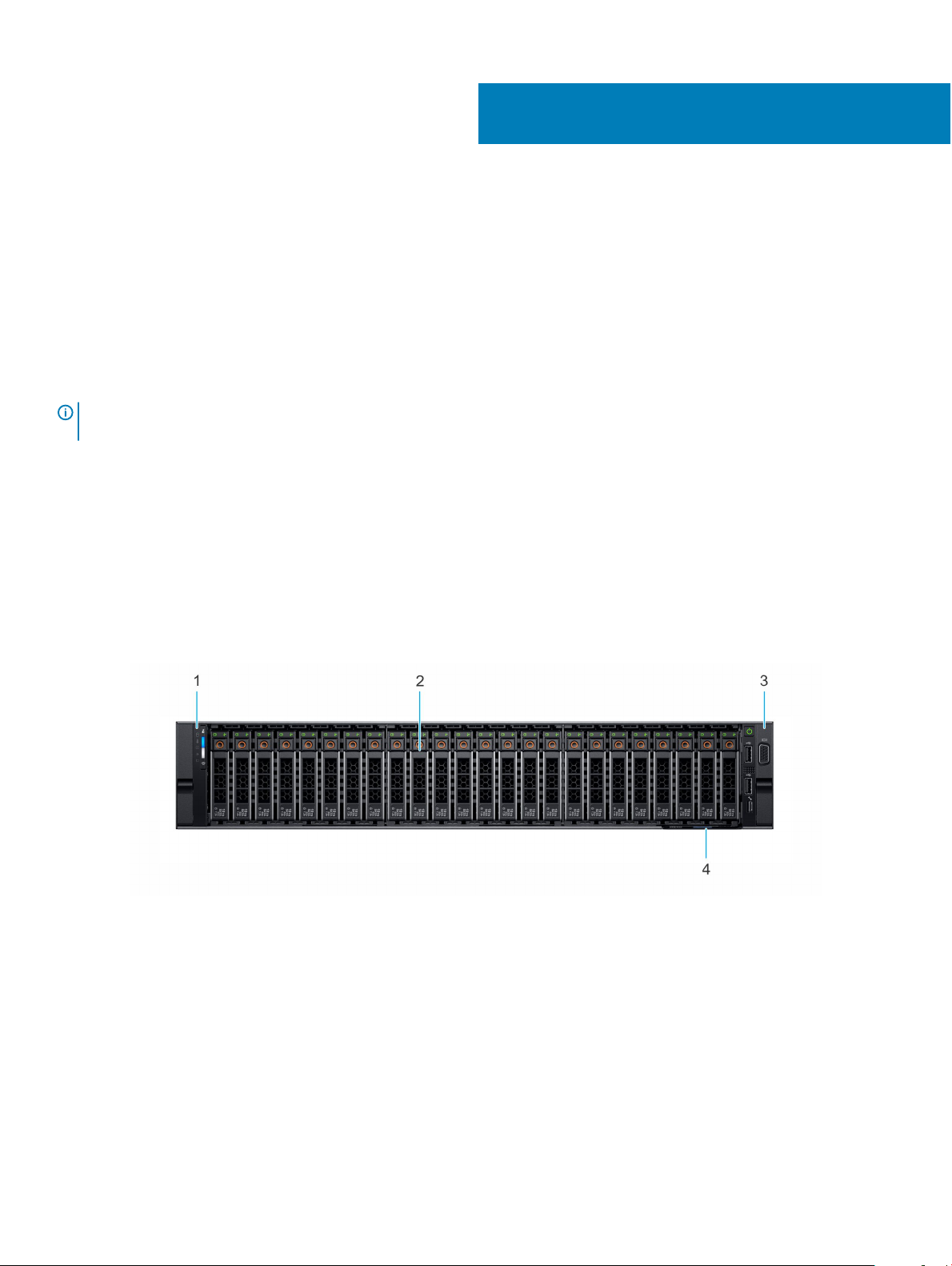
Figure 1. Front view 24 x 2.5-inch drive system
Left control panel 2 Drives
1
3 Right control panel 4 Service Tag
Dell EMC PowerEdge R840 system overview 5
Page 6
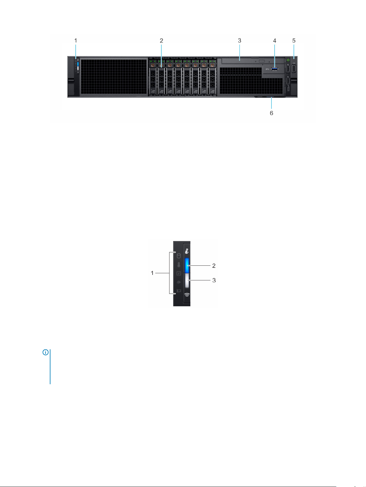
Figure 2. Front view 8 x 2.5-inch drive system
1 Left control panel 2 Drive slots
3 Optical drive (Optional) 4 USB 3.0 port (Optional)
5 Right control panel 6 Service Tag
For more information about the ports, see the Technical Specications section.
Control panels
Left control panel
Figure 3. Left control panel view (with optional iDRAC Quick Sync 2.0 indicator)
1
Status LED indicators 2 System health and system ID indicator
3 iDRAC Quick Sync 2 wireless indicator (optional)
NOTE: iDRAC Quick Sync 2 feature allows you to
manage your system using mobile devices. This feature
is only available on certain congurations. For more
information about the feature, see the Integrated Dell
Remote Access Controller User's Guide at
www.dell.com/idracmanuals.
6 Dell EMC PowerEdge R840 system overview
Page 7
Right control panel view
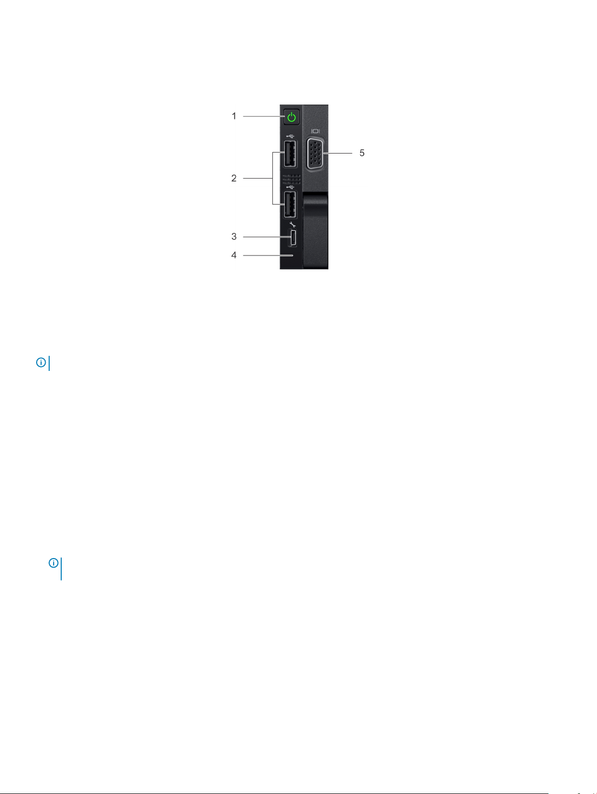
Figure 4. Right control panel view
1 Power button 2 USB 2.0 port (2)
3 iDRAC Direct port 4 iDRAC Direct LED
5 VGA port
NOTE: For more information on the ports, see the Technical Specications section.
LCD panel
The LCD panel provides system information, status, and error messages to indicate if the system is functioning correctly or requires
attention. The LCD panel can also be used to congure or view the system’s iDRAC IP address. For information about the event and error
messages generated by the system rmware and agents that monitor system components, see the Error Code Lookup page, at
qrl.dell.com.
The LCD panel is available only on the optional front bezel. The optional front bezel is hot pluggable.
The statuses and conditions of the LCD panel are outlined here:
• The LCD backlight is white during normal operating conditions.
• When the system needs attention, the LCD backlight turns amber, and displays an error code followed by descriptive text.
NOTE
: If the system is connected to a power source and an error is detected, the LCD turns amber regardless of whether the
system is turned on or o.
• When the system turns o and there are no errors, LCD enters the standby mode after ve minutes of inactivity. Press any button on
the LCD to turn it on.
• If the LCD panel stops responding, remove the bezel and reinstall it.
If the problem persists, see Getting help.
• The LCD backlight remains o if LCD messaging is turned o using the iDRAC utility, the LCD panel, or other tools.
Dell EMC PowerEdge R840 system overview
7
Page 8
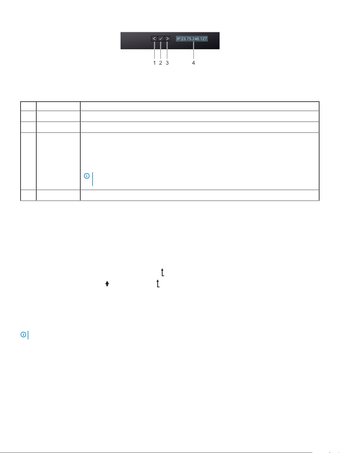
Figure 5. LCD panel features
Table 1. LCD panel features
Item Button or display Description
1 Left Moves the cursor back in one-step increments.
2 Select Selects the menu item highlighted by the cursor.
3 Right Moves the cursor forward in one-step increments.
During message scrolling:
• Press and hold the right button to increase scrolling speed.
• Release the button to stop.
NOTE: The display stops scrolling when the button is released. After 45 seconds of inactivity, the
display starts scrolling.
4 LCD display Displays system information, status, and error messages or iDRAC IP address.
Viewing Home screen
The Home screen displays user-congurable information about the system. This screen is displayed during normal system operation when
there are no status messages or errors. When the system turns o and there are no errors, LCD enters the standby mode after ve
minutes of inactivity. Press any button on the LCD to turn it on.
1 To view the Home screen, press one of the three navigation buttons (Select, Left, or Right).
2 To navigate to the Home screen from another menu, complete the following steps:
a Press and hold the navigation button till the up arrow is displayed.
b Navigate to the Home icon using the up arrow .
c Select the Home icon.
d On the Home screen, press the Select button to enter the main menu.
Setup menu
NOTE
: When you select an option in the Setup menu, you must conrm the option before proceeding to the next action.
Option Description
iDRAC Select DHCP or Static IP to congure the network mode. If Static IP is selected, the available elds are IP,
Subnet (Sub), and Gateway (Gtw). Select Setup DNS to enable DNS and to view domain addresses. Two
separate DNS entries are available.
Set error Select SEL to view LCD error messages in a format that matches the IPMI description in the SEL. This enables you
to match an LCD message with an SEL entry.
8 Dell EMC PowerEdge R840 system overview
Page 9
Option Description
Select Simple to view LCD error messages in a simplied user-friendly description. For information about the event
and error messages generated by the system rmware and agents that monitor system components, see the Error
Code Lookup page, at qrl.dell.com
Set home Select the default information to be displayed on the Home screen. See View menu section for the options and
option items that can be set as the default on the Home screen.
View menu
NOTE: When you select an option in the View menu, you must conrm the option before proceeding to the next action.
Option Description
iDRAC IP Displays the IPv4 or IPv6 addresses for iDRAC9. Addresses include DNS (Primary and Secondary), Gateway, IP,
and Subnet (IPv6 does not have Subnet).
MAC Displays the MAC addresses for iDRAC, iSCSI, or Network devices.
Name Displays the name of the Host, Model, or User String for the system.
Number Displays the Asset tag or the Service tag for the system.
Power Displays the power output of the system in BTU/hr or Watts. The display format can be congured in the Set
home submenu of the Setup menu.
Temperature Displays the temperature of the system in Celsius or Fahrenheit. The display format can be congured in the Set
home submenu of the Setup menu.
Rear view of the system
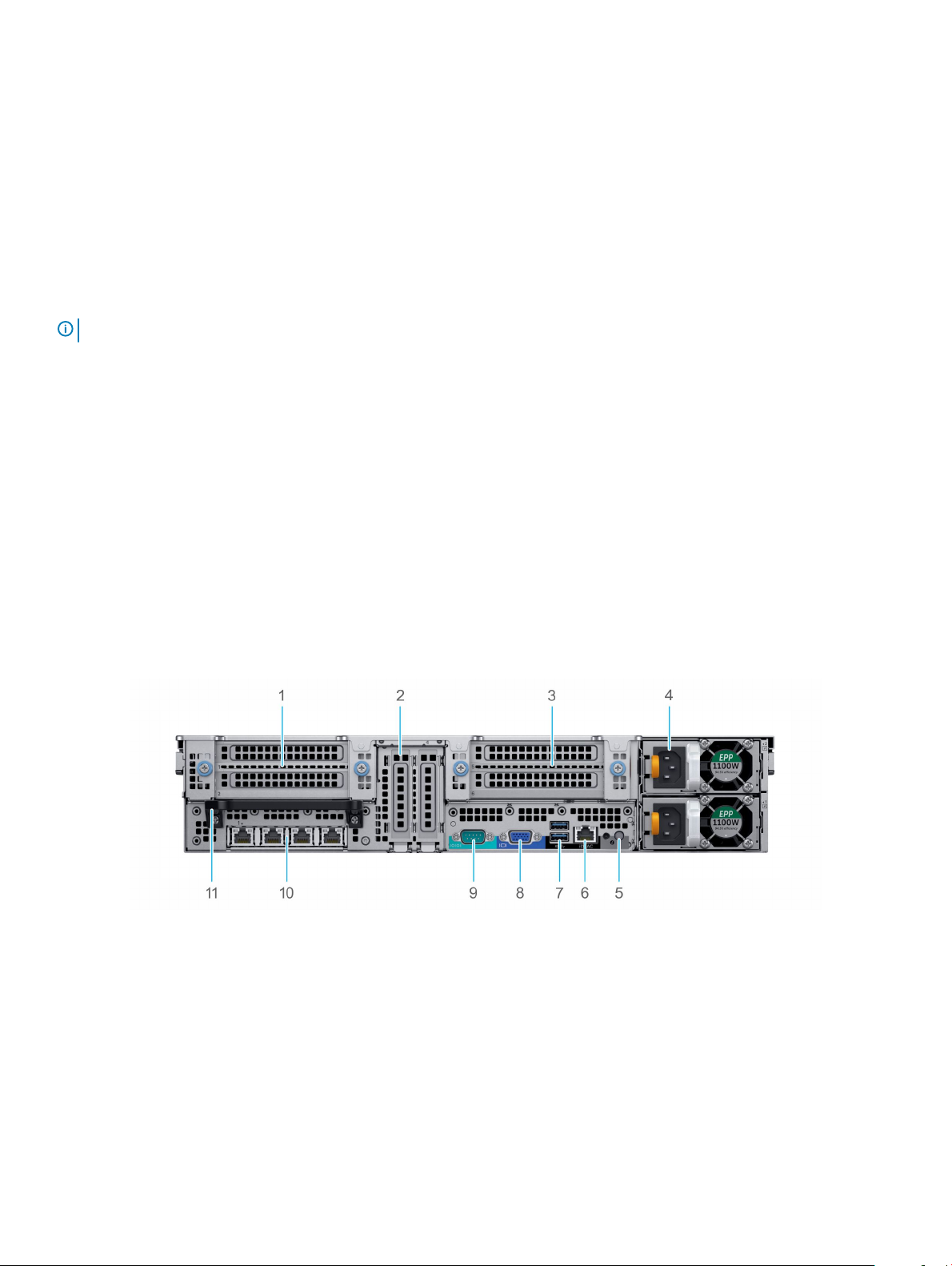
Figure 6. Rear view of the 24 x 2.5-inch drive system
Riser 1 - Full-height PCIe expansion card (Slot 1 and 2) 2 Half-height PCIe expansion card slots located on the system
1
3 Riser 2 -Full-height PCIe expansion card slots (Slot 5 and 6) 4 Power supply units (2)
5 System identication button 6 iDRAC9 dedicated port
7 USB 3.0 ports (2) 8 VGA port
9 Serial port 10 NIC ports (4)
11 Rear handle
board (Slot 3 and 4)
Dell EMC PowerEdge R840 system overview 9
Page 10
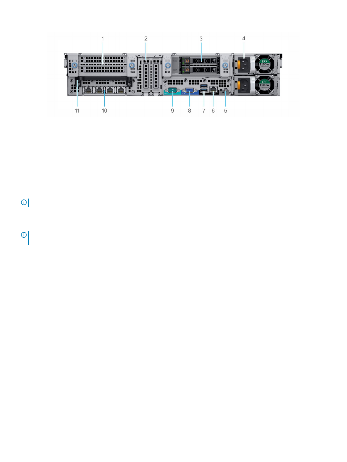
Figure 7. Rear view of the 24 x 2.5-inch + 2 x 2.5-inch (rear) drive system
1 Riser 1 - Full-height PCIe expansion card slots (Slot 1 and 2) 2 Half-height PCIe expansion card slots located on the system
3 Rear drives (2) 4 Power supply units (2)
5 System identication button 6 iDRAC9 dedicated port
7 USB 3.0 ports (2) 8 VGA port
9 Serial port 10 NIC ports (4)
11 Rear handle
NOTE: For more information about the ports and connectors, see the Technical Specications section.
board (Slot 3 and 4)
Inside the system
NOTE
: Components that are hot swappable have orange touch points and the components that are not hot swappable have blue
touch points.
10 Dell EMC PowerEdge R840 system overview
Page 11
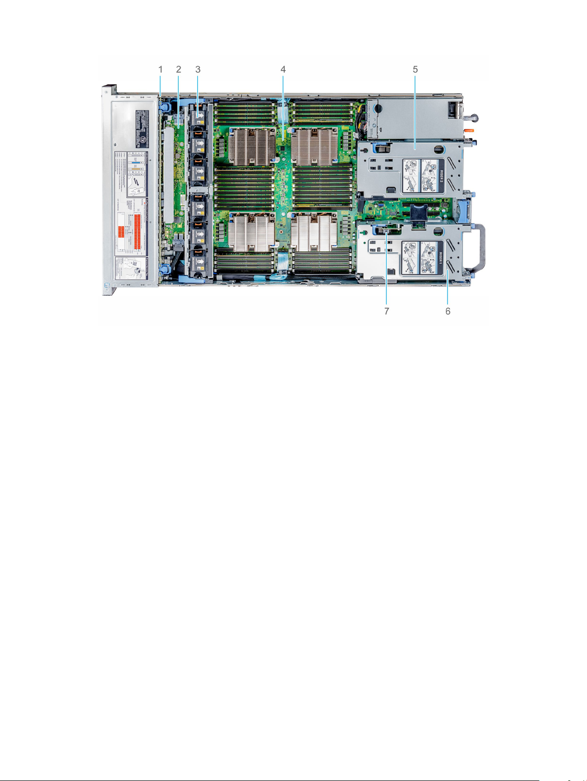
Figure 8. Inside the system without rear drive cage
1
Drive backplane 2 SAS Expander board
3 Cooling fans (6) 4 System board
5 Full-height expansion card Riser 2 6 Full-height expansion card Riser 1
7 Intrusion switch
Dell EMC PowerEdge R840 system overview 11
Page 12
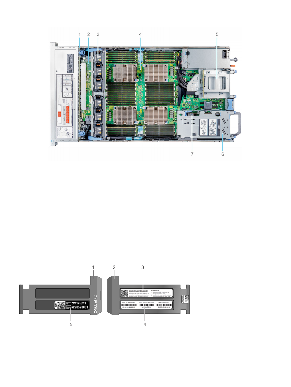
Figure 9. Inside the system with rear drive cage
1
Drive backplane 2 SAS Expander board
3 Cooling fans (6) 4 System board
5 Drive cage (rear) 6 Full-height expansion card Riser 1
7 Intrusion switch
Locating the Service Tag of your system
You can identify your system using the unique Express Service Code and Service Tag. Pull out the information tag in front of the system to
view the Express Service Code and Service Tag. Alternatively, the information may be on a sticker on the chassis of the system. The mini
Enterprise Service Tag (EST) is found on the back of the system. This information is used by Dell to route support calls to the appropriate
personnel.
Figure 10. Locating Service Tag of your system
1 Information tag (top view)
2 Information tag (bottom view)
3 OpenManage Mobile (OMM) label (optional)
Dell EMC PowerEdge R840 system overview
12
Page 13
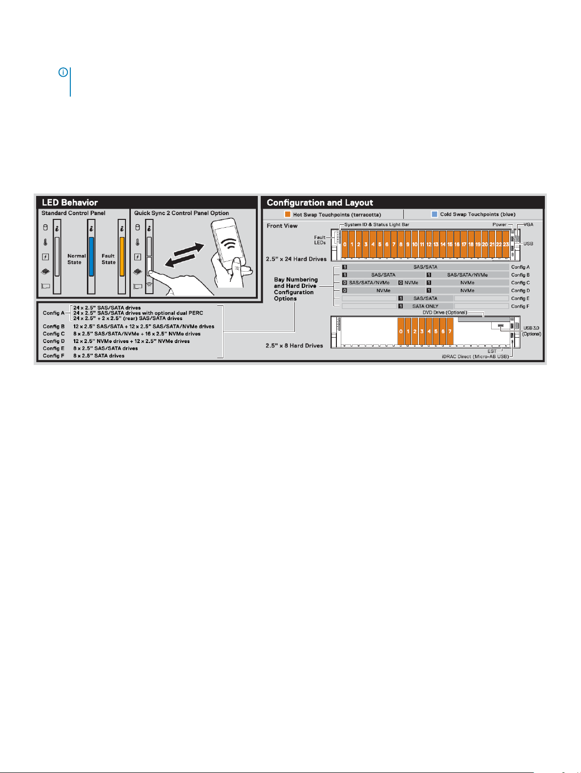
4 iDRAC MAC address and iDRAC secure password label
NOTE: If you have opted for secure default access to iDRAC, the iDRAC secure default password is available on the back of
the system Information tag. This section of label will be blank, if you have not opted for secure default access to iDRAC,
then the default user name and password are root and calvin.
5 Service Tag
System Information Label
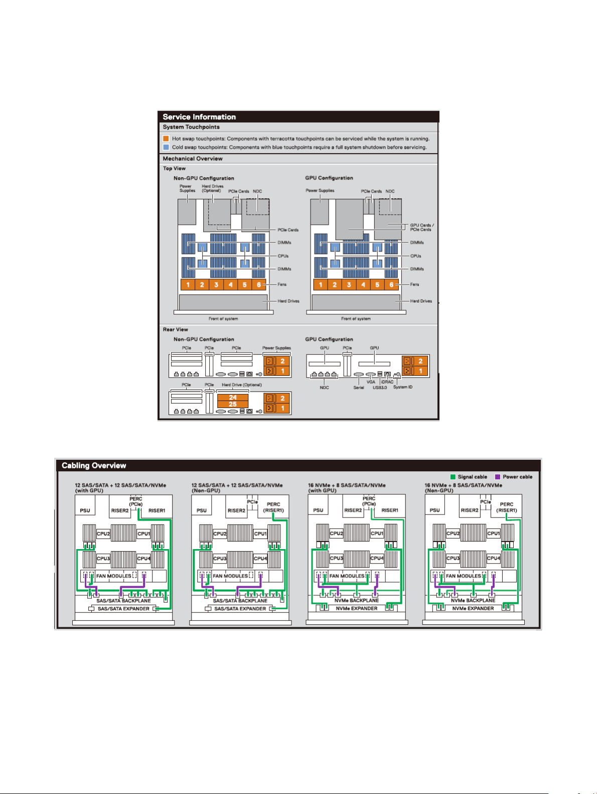
PowerEdge R840 – Front system information label
Figure 11. LED behavior, and Conguration and Layout
Dell EMC PowerEdge R840 system overview
13
Page 14
PowerEdge R840 – Service information
Figure 12. Mechanical overview
Figure 13. Signal and power cable routing
Dell EMC PowerEdge R840 system overview
14
Page 15
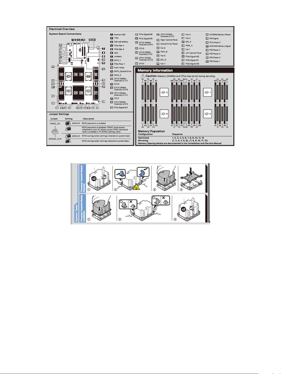
Figure 14. Electrical overview
Figure 15. CPU installation
Dell EMC PowerEdge R840 system overview
15
Page 16
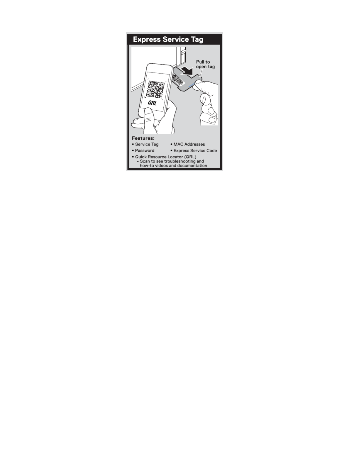
Figure 16. Express service tag
16 Dell EMC PowerEdge R840 system overview
Page 17

Technical specications
The technical and environmental specications of your system are outlined in this section.
Topics:
• Chassis dimensions
• Chassis weight
• Processor specications
• Supported operating systems
• PSU specications
• System battery specications
• Expansion card riser specications
• Memory specications
• RAID controller specications
• Drive specications
• Ports and connectors specications
• Video specications
• Environmental specications
2
Technical specications 17
Page 18
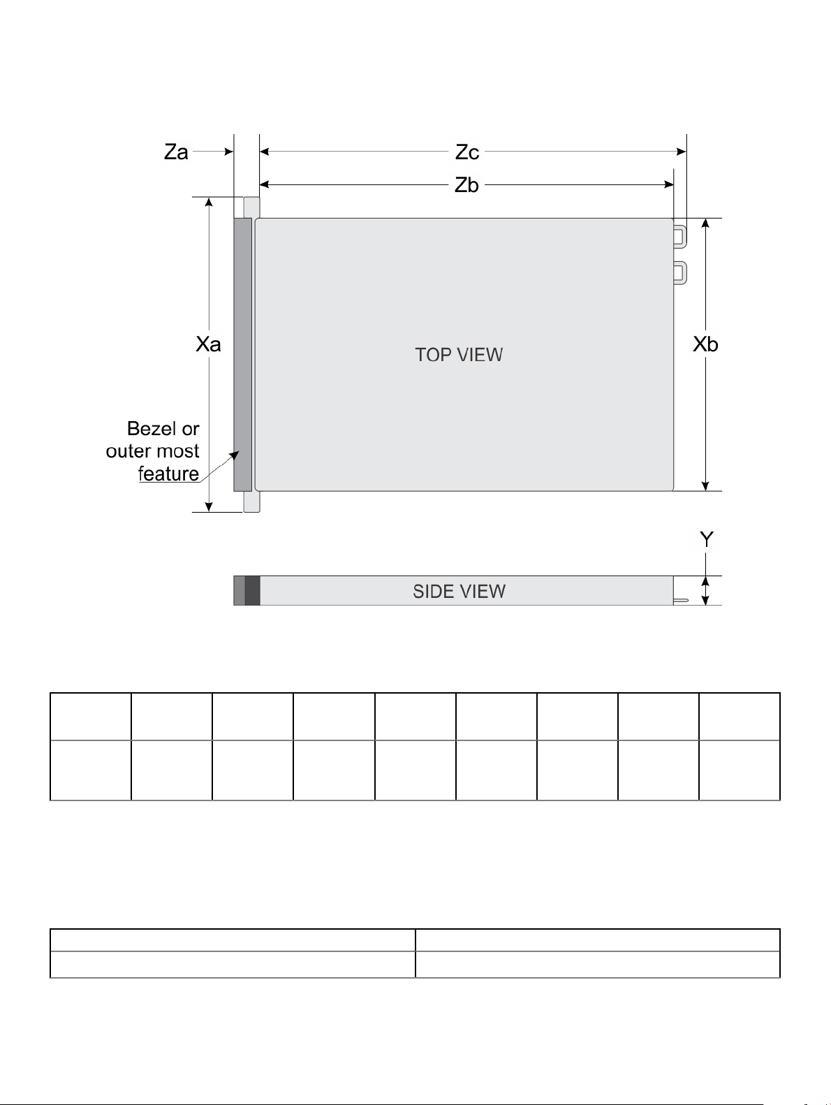
Chassis dimensions
Figure 17. Dimensions of PowerEdge R840 system
Table 2. Dimensions of
Xa Xb (without
482 mm
(18.97
inches)
* - Zb refers to the nominal rear wall external surface, where the system board I/O connectors are located.
PowerEdge R840 system
brackets)
434 mm
(17.08
inches)
Xb (w
brackets)
444.0 (17.48
inches)
Y Za (with
86.8 mm
(3.41 inches)
bezel)
37.84 mm
(1.41 inches)
Za (without
bezel)
23.9 mm
(0.94 inches)
Zb* Zc (with
812 mm
(31.96
inches)
Chassis weight
Table 3. Chassis weight
System Maximum weight (with all drives/SSDs)
2.5 inch 36.6 kg (80.68 lb)
PSU handle)
842 mm
(33.14
inches)
Zc (with
chassis rear
wall handle)
902 mm
(35.51
inches)
18 Technical specications
Page 19

Processor specications
The PowerEdge R840 system supports four processors - Intel Xeon Scalable Processor family.
Supported operating systems
The PowerEdge R840 supports the following operating systems:
• Canonical Ubuntu LTS Citrix XenServer
• Microsoft Windows Server with Hyper-V
• Red Hat Enterprise Linux
• SUSE Linux Enterprise Server
• VMware ESXi
For more information on the specic versions and additions, see https://www.dell.com/support/home/Drivers/SupportedOS/poweredge-
r840.
PSU specications
The PowerEdge R840 system supports up to two AC or DC power supply units (PSUs).
Table 4. PSU specications
PSU Class Heat
750 W AC Platinum 2891 BTU/hr 50/60 Hz 100–240 V
750 W AC Titanium 2843 BTU/hr 50/60 Hz 200–240 V
750 W
Mixed Mode
HVDC (for
China only)
1100 W AC Platinum 4100 BTU/hr 50/60 Hz 100–240 V
1100 W DC N/A 4416 BTU/hr N/A –(48–60) V
1100 W
10 A-5 A
Mixed Mode
HVDC (for
China and
Japan only)
Platinum 2891 BTU/hr 50/60 Hz 100–240 V
N/A 2891 BTU/hr N/A 240 V DC,
Platinum 4100 BTU/hr 50/60 Hz 100–240 V
N/A 4100 BTU/hr N/A 200–380 V
dissipation
(maximum)
Frequency Voltage High line
AC,
autoranging
AC,
autoranging
AC,
autoranging
autoranging
AC,
autoranging
DC,
autoranging
AC,
autoranging
DC,
autoranging
200V–240 V
750 W 750 W NA 10 A-5 A
750 W NA NA 5 A
750 W 750 W NA NA
NA NA 750 W 4.5 A
1100 W 1050 W NA 12 A-6.5 A
NA NA 1100 W 32 A
1100 W 1050 W NA 12 A-6.5 A
NA NA 1100 W 6.4 A-3.2 A
Low line 100
V– 140 V
DC Current
Technical specications 19
Page 20
PSU Class Heat
dissipation
(maximum)
Frequency Voltage High line
200V–240 V
Low line 100
V– 140 V
DC Current
1600 W AC Platinum 6000
BTU/hr
2000 W AC Platinum 7500 BTU/hr 50/60 Hz 100–240 V
2400 W AC Platinum 9000
BTU/hr
NOTE: Heat dissipation is calculated using the PSU wattage rating.
NOTE: This system is also designed to connect to the IT power systems with a phase-to-phase voltage not exceeding 240 V.
NOTE: PSUs rated for 1100 W AC or 1100 W Mixed Mode HVDC and higher require high-line voltage (200–240 V AC) to supply
their rated capacity.
50/60 Hz 100–240 V
AC,
autoranging
AC,
autoranging
50/60 Hz 100–240 V
AC,
autoranging
1600 W 800 W NA 10 A
2000 W 1000 W NA 11.5 A
2400 W 1400 W NA 16 A
System battery specications
The PowerEdge R840 system supports CR 2032 3.0-V lithium coin cell system battery.
Expansion card riser specications
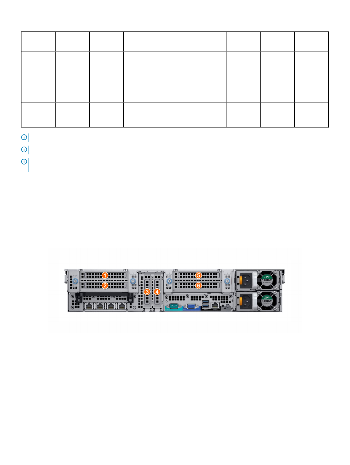
The PowerEdge R840 system supports up to six PCI express (PCIe) generation 3 expansion cards that can be installed on the system
board and expansion card risers.
Figure 18. 24 x 2.5-inch drive system
Technical specications
20
Page 21
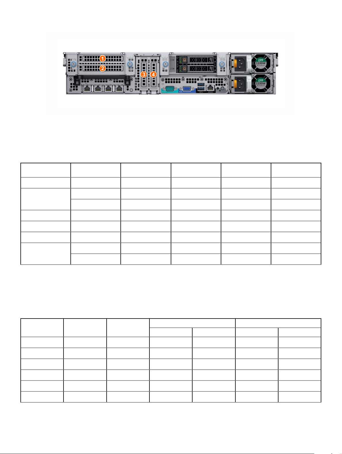
Figure 19. 24 x 2.5-inch + 2 x 2.5-inch (rear) drive system
The following table provides detailed information about the expansion card riser specications:
Table 5. Expansion card riser specications
PCIe slot Riser Processor
connection
1 X8 PCIe Riser 1 Processor 1 Full height Half length x8
2 X16 PCIe Riser 1 Processor 1 Full height Full length x16
X8 PCIe Riser 1 Processor 1 Full height Half length x8
3 On the system board Processor 1 Low prole Half length x16
4 On the system board Processor 2 Low prole Half length x16
5 X8 PCIe Riser 2 Processor 2 Full height Half length x8
6 X16 PCIe Riser 2 Processor 2 Full height Full length x16
X8 PCIe Riser 2 Processor 2 Full height Half length x8
Height Length Slot width
Memory specications
The PowerEdge R840 system supports up to 48 288-pins RDIMMs, LRDIMMs, and NVDIMM-Ns supported with speeds of 2667 MT/s,
2400 MT/s, 2133 MT/s, and 1866 MT/s with support for memory optimized operation.
Table 6. Memory
DIMM type DIMM rank DIMM capacity
specications
Dual processors Quad processors
Minimum RAM Maximum RAM Minimum RAM Maximum RAM
LRDIMM Octal rank 128 GB 256 GB 3072 GB 512 GB 6144 GB
LRDIMM Quad rank 64 GB 128 GB 1536 GB 256 GB 3072 GB
RDIMM Dual rank 32 GB 64 GB 768 GB 128 GB 1536 GB
RDIMM Dual rank 16 GB 32 GB 384 GB 64 GB 768 GB
RDIMM Single rank 8 GB 16 GB 192 GB 32 GB 384 GB
NVDIMM-N Single rank 16 GB RDIMM: 192 GB RDIMM: 384 GB RDIMM: 384 GB RDIMM: 1152 GB
Technical specications 21
Page 22
DIMM type DIMM rank DIMM capacity
Minimum RAM Maximum RAM Minimum RAM Maximum RAM
NVDIMM-N: 16 GBNVDIMM-N: 192 GBNVDIMM-N: 16 GBNVDIMM-N: 192
NOTE: Do not mix 8 GB RDIMMs and 16 GB NVDIMM-Ns.
NOTE: Do not mix 64 GB LRDIMMs and 128 GB LRDIMMs.
Table 7. DIMM blank population rules
Processor conguration Processor 1 Processor 2 Processor 3 Processor 4
Dual processor Required Required Not required Not required
Quad processor Required Required Required Required
Dual processors Quad processors
GB
RAID controller specications
The PowerEdge R840 system supports:
• Internal storage controller cards: PowerEdge RAID Controller (PERC) H330, PERC H730P, H740P, HBA330, and Boot Optimized Server
Storage (BOSS-S1)
• External storage controller cards: S140 and 12 Gbps SAS HBA
Drive specications
Drives
The PowerEdge R840 system supports SAS, SATA, Nearline SAS hard drives/SSDs, or NVMe drives.
Table 8. Supported drive options for PowerEdge R840 system
Chassis options Congurations
Eight hard drive chassis
Twenty-four drive chassis
Twenty four front + two
rear drive chassis
Up to eight 2.5-inch SAS/SATA front accessible drives in slots 0–7
Up to eight 2.5-inch SATA front accessible drives in slots 0–7
Up to twenty-four 2.5-inch SAS/SATA front accessible drives in slots 0–23
Up to twelve 2.5-inch SAS/SATA front accessible drives in slots 0–11 + twelve SAS/SATA/NVMe front
accessible drives in slots 12–23
Up to twenty-four 2.5-inch NVMe front accessible drives in slots 0–23
Up to twenty-four 2.5 inch SAS/SATA front accessible drives in slots 0–23 + up to two 2.5-inch SAS/SATA
rear accessible drives
Optical drives
The PowerEdge R840 system supports one optional slim SATA DVD-ROM drive or DVD +/-RW drive.
Technical specications
22
Page 23
NOTE: DVD devices support only data.
Tape drives
The PowerEdge R840 system supports external tape backup devices.
NOTE: The PowerEdge R840 system does not support internal tape drives.
Supported external tape drives:
• External RD1000 USB
• External LTO-5, LTO-6,LTO-7, and 6 Gb SAS tape drives
• 114X rack mount chassis with LTO-5, LTO-6, and LTO-7, 6 Gb SAS tape drives
• TL1000 with LTO-5, LTO-6, and LTO-7 6 Gb SAS tape drives
• TL2000 with LTO-5, LTO-6, and LTO-7 6 Gb SAS tape drives
• TL2000 with LTO-5, LTO-6, and LTO-7 8 Gb FC tape drives
• TL4000 with LTO-5, LTO-6, and LTO-7 6 Gb SAS tape drives
• TL4000 with LTO-5, LTO-6, and LTO-7 8 Gb FC tape drives
• ML6000 with LTO-5, LTO-6, 6 Gb SAS tape drives
• ML6000 with LTO-5, LTO-6, LTO-7 8 Gb FC tape drives
Ports and connectors specications
USB ports
The PowerEdge R840 system supports both USB 2.0-compliant ports and USB 3.0-compliant ports:
The following table provides more information about the USB specications:
Table 9. USB
Front panel Back panel Internal USB
• Two USB 2.0-compliant ports
• One micro USB 2.0-compliant port
for iDRAC Direct
• One optional USB 3.0-compliant port
specications
• Two USB 3.0-compliant ports • One internal USB 3.0-compliant port
NOTE: The micro USB 2.0
compliant port can only be
used as an iDRAC Direct or a
management port.
NIC ports
The PowerEdge R840 system supports up to four Network Interface Controller (NIC) ports that are integrated on the network daughter
card (NDC), and are available in the following congurations:
• Four RJ-45 ports that support 10 Mbps, 100 Mbps, and 1000 Mbps
• Four RJ-45 ports that support 100 M, 1 G, and 10 Gbps
Technical
specications 23
Page 24

• Four RJ-45 ports, where two ports support maximum of 10 G and the other two ports maximum of 1 G
• Two RJ-45 ports that support up to 1 Gbps and 2 SFP+ ports that support up to 10 Gbps
• Four SFP+ ports that support up to 10 Gbps
• Two SFP28 ports that support up to 25 Gbps
VGA ports
The Video Graphic Array (VGA) port enables you to connect the system to a VGA display.
The PowerEdge R840 system supports two 15-pin VGA ports, one each, on the front and back of the system.
Serial connector
The serial connector on the rear of system for serial device connection and console redirection.
The PowerEdge R840 system supports one serial connector on the back panel, which is a 9-pin connector, Data Terminal Equipment
(DTE), 16550-compliant.
IDSDM or vFlash module
The PowerEdge R840 system supports optional Internal Dual SD module (IDSDM) or vFlash module. In 14th generation of PowerEdge
servers, IDSDM or vFlash module is combined into a single card module, and are available in these congurations:
• vFlash or
• vFlash and IDSDM
The IDSDM or vFlash module is located in a slot on the back of the system. The module supports three microSD cards; two cards for
IDSDM and one card for vFlash. The following capacities are supported:
• IDSDM: 16 GB, 32 GB, 64 GB
• vFlash: 16 GB
NOTE
: There are two dip switches on the IDSDM or vFlash module for write-protection.
NOTE: One IDSDM card slot is dedicated for redundancy.
NOTE: Use Dell branded microSD cards associated with the IDSDM or vFlash congured systems.
Video specications
The PowerEdge R840 system supports integrated Matrox G200eW3 graphics controller with 16 MB of video frame buer.
Table 10. Supported video resolution options
Resolution Refresh rate (Hz) Color depth (bits)
1024 x 768 60 8, 16, 32
1280 x 800 60 8, 16, 32
1280 x 1024 60 8, 16, 32
1360 x 768 60 8, 16, 32
24 Technical specications
Page 25

Resolution Refresh rate (Hz) Color depth (bits)
1440 x 900 60 8, 16, 32
1600 x 900 60 8, 16, 32
1600 x 1200 60 8, 16, 32
1680 x 1050 60 8, 16, 32
1920 x 1080 60 8, 16, 32
1920 x 1200 60 8, 16, 32
NOTE: 1920 x 1080 and 1920 x 1200 resolutions are only supported in reduced blanking mode.
Environmental specications
NOTE: For additional information about environmental certications, please refer to the Product Environmental Datasheet
located with the Manuals & Documents on support.dell.com.
Table 11. Temperature specications
Temperature Specications
Storage –40–65°C (–40 °F–149°F)
Continuous operation (for altitude less than 950 m or
3117 ft)
Fresh air For information about fresh air, see the Expanded Operating Temperature section.
Maximum temperature gradient (operating and
storage)
Table 12. Relative humidity specications
Relative humidity Specications
Storage 5% to 95% RH with 33°C (91°F) maximum dew point. Atmosphere must be
Operating 10% to 80% RH with 29°C (84.2°F) maximum dew point.
Table 13. Maximum vibration specications
Maximum vibration Specications
Operating 0.26 G
Storage 1.88 G
10–35°C (50 °F–95°F) with no direct sunlight on the equipment
20°C/h (36°F/h)
noncondensing at all times.
at 5 Hz to 350 Hz (all operation orientations)
rms
at 10 Hz to 500 Hz for 15 minutes (all six sides tested)
rms
Technical specications 25
Page 26

Table 14. Maximum shock pulse specications
Maximum shock pulse Specications
Operating Six consecutively executed shock pulses in the positive and negative x, y, and z
axes of 6 G for up to 11 ms.
Storage Six consecutively executed shock pulses in the positive and negative x, y, and z
axes (one pulse on each side of the system) of 71 G for up to 2 ms.
Table 15. Maximum altitude specications
Maximum altitude Specications
Operating 3048 m (10,000 ft)
Storage 12,000 m (39,370 ft)
Table 16. Operating temperature derating specication
Operating temperature derating Specications
Up to 35°C (95°F) Maximum temperature is reduced by 1°C/300 m (1°F/547 ft), above 950 m (3,117
ft).
35–40 °C (95–104 °F) Maximum temperature is reduced by 1°C/175 m (1°F/319 ft), above 950 m (3,117
ft).
40–45 °C (104 °F–113 °F) Maximum temperature is reduced by 1°C/125 m (1°F/228 ft), above 950 m (3,117
ft).
Standard operating temperature
Table 17. Standard operating temperature
Standard operating temperature Specications
Continuous operation (for altitude less than 950 m or 3117
ft)
specications
10 °C–35°C (50 °F–95°F) with no direct sunlight on the equipment.
Expanded operating temperature
Table 18. Expanded operating temperature
Expanded operating temperature Specications
Continuous operation 5 °C–40°C at 5% to 85% RH with 29°C dew point.
specications
NOTE: Outside the standard operating temperature
(10 °C–35°C), the system can operate continuously in
temperatures as low as 5°C and as high as 40°C.
26 Technical specications
Page 27

Expanded operating temperature Specications
For temperatures 35 °C – 40°C, derate maximum allowable
temperature by 1°C per 175 m (1°F per 319 ft.) above 950 m (3,1171
ft.).
≤ 1% of annual operating hours –5 °C–45°C at 5% to 90% RH with 29°C dew point.
NOTE: Outside the standard operating temperature
(10 °C–35°C), the system can operate down to –5°C or
up to 45°C for a maximum of 1% of its annual operating
hours.
For temperatures 40 °C – 45°C, derate maximum allowable
temperature by 1°C per 125 m (1°F per 228 ft.) above 950 m (3.117
ft.).
NOTE: When operating in the expanded temperature range, the performance of the system may be impacted.
NOTE: When operating in the expanded temperature range, ambient temperature warnings may be reported on the LCD panel
and in the System Event Log.
Expanded operating temperature restrictions
• The operating temperature is specied for a maximum altitude of 950 m for Fresh Air Cooling.
• Do not perform cold start below 5°C due to hard drive constraints.
• Apache Pass DIMM, NVDIMM, PCIe SSD, and NVMe are not supported.
• Tape Backup Unit (TBU) is not supported in Fresh Air.
• LRDIMM >32 GB is not supported in x4 sockets conguration.
• Rear installed drives and GPU conguration are not supported.
• Redundant power supplies are required.
• Non Dell qualied peripheral cards and /or peripheral cards greater than 25 W are not supported.
• Intel FPGA is not supported.
• 205 W SKUs, 200W/18C, 165W/12C, and 150W_8C processor are not supported on all x4 socket processor congurations.
• 165 W SKUs, 130W/8C, 115W/6C, and 105W_4C are not supported on the x4 socket processor congurations except front x8 inch
SAS/SATA drives congurations.
Ambient temperature limitations
NOTE
: The ambient temperature limit must be adhered to ensure proper cooling and to avoid excess processor throttling, which
may impact system performance.
Technical specications 27
Page 28
Table 19. Conguration-based ambient temperature restrictions
R840 congurations Backplane 8 x 2.5 inch
R840 congurations No. Of
processors
supported
Processor heat
sink
No. Of GPUs
supported
Supported
processor
Intel Xeon
Platinum 8176
Intel Xeon
Platinum 8170
Intel Xeon Gold
6150
Processor
Thermal Design
Power (TDP)
165 W 28 C35 C30 C30 C35
165 W 26 C35 C30 C30 C35
165 W 18 C35 C30 C30 C35
Core count Ambient support Ambient support Ambient support Ambient support
SAS/SATA
4 4 4 2
1U 1U 1U 1U
>1DW/SW GPU >1DW/SW GPU >1DW/SW GPU >1DW/SW GPU
24 x 2.5 inch
SAS/
SATA(Expander)
+ 2x 2.5
inch(rear)
24 x 2.5-inch
NVMe(Expander
)
24 x 2.5 inch
SAS/SATA/
NVMe(Expander
)
Intel Xeon Gold
6134
Intel Xeon Gold
6128
Intel Xeon Gold
5122
Intel Xeon
Platinum 8156
Intel Xeon
Platinum 8164
Intel Xeon
Platinum 8160
Intel Xeon Gold
6148
Intel Xeon Gold
6142
Intel Xeon Gold
6136
Intel Xeon
Platinum 8158
130 W 8 C35 C30 C30 C35
115 W 6 C35 C30 C30 C35
105 W 4 C35 C30 C30 C35
105 W 4 C35 C30 C30 C35
150 W 26 C35 C30 C30 C35
150 W 24 C35 C30 C30 C35
150 W 20 C35 C30 C30 C35
150 W 16 C35 C30 C30 C35
150 W 12 C35 C30 C30 C35
150 W 12 C35 C30 C30 C35
Intel Xeon Gold
6152
28 Technical specications
140 W 22 C35 C30 C30 C35
Page 29
R840 congurations Backplane 8 x 2.5 inch
SAS/SATA
24 x 2.5 inch
SAS/
SATA(Expander)
+ 2x 2.5
inch(rear)
24 x 2.5-inch
NVMe(Expander
)
24 x 2.5 inch
SAS/SATA/
NVMe(Expander
)
Intel Xeon Gold
6140
Intel Xeon Gold
6132
Intel Xeon Gold
6138
Intel Xeon Gold
6130
Intel Xeon
Platinum 8153
Intel Xeon Gold
6126
Intel Xeon Gold
5120
Intel Xeon Gold
5118
Intel Xeon Gold
5115
140 W 18 C35 C30 C30 C35
140 W 14 C35 C30 C30 C35
125 W 20 C35 C30 C30 C35
125 W 16 C35 C30 C30 C35
125 W 16 C35 C30 C30 C35
125 W 12 C35 C30 C30 C35
105 W 14 C35 C30 C30 C35
105 W 12 C35 C30 C30 C35
85 W 10 C35 C30 C30 C35
Table 20. Conguration-based ambient temperature restrictions
R840 congurations Backplane 8 x 2.5 inch
R840 congurations No. Of
processors
supported
Processor heat
sink
No. Of GPUs
supported
Supported
processor
Intel Xeon
Platinum 8180
Intel Xeon
Platinum 8168
Intel Xeon Gold
6154
Processor
Thermal Design
Power (TDP)
205 W 28 C35 C30 C30 C35
205 W 24 C35 C30 C30 C35
200 W 18 C35 C30 C30 C35
Core count Ambient support Ambient support Ambient support Ambient support
SAS/SATA
4 4 4 2
1U 1U 1U 1U
Non-GPU Non-GPU Non-GPU Non-GPU
24 x 2.5 inch
SAS/
SATA(Expander)
+ 2x 2.5
inch(rear)
24 x 2.5-inch
NVMe(Expander
)
24 x 2.5 inch
SAS/SATA/
NVMe(Expander
)
Technical specications 29
Page 30
R840 congurations Backplane 8 x 2.5 inch
SAS/SATA
24 x 2.5 inch
SAS/
SATA(Expander)
+ 2x 2.5
inch(rear)
24 x 2.5-inch
NVMe(Expander
)
24 x 2.5 inch
SAS/SATA/
NVMe(Expander
)
Intel Xeon Gold
6146
Intel Xeon Gold
6144
Intel Xeon
Platinum 8176
Intel Xeon
Platinum 8170
Intel Xeon Gold
6150
Intel Xeon Gold
6134
Intel Xeon Gold
6128
Intel Xeon Gold
5122
Intel Xeon
Platinum 8156
Intel Xeon
Platinum 8164
165 W 12 C35 C30 C30 C35
150 W 8 C35 C30 C30 C35
165W 28 C35 C35 C30 C35
165 W 26 C35 C35 C30 C35
165 W 18 C35 C35 C30 C35
130 W 8 C35 C35 C35 C35
115 W 8 C35 C35 C35 C35
105 W 6 C35 C35 C35 C35
105 W 4 C35 C35 C35 C35
150 W 4 C35 C35 C35 C35
Intel Xeon
Platinum 8160
Intel Xeon Gold
6148
Intel Xeon Gold
6142
Intel Xeon Gold
6136
Intel Xeon
Platinum 8158
Intel Xeon Gold
6152
Intel Xeon Gold
6140
Intel Xeon Gold
6132
Intel Xeon Gold
6138
150 W 26 C35 C35 C35 C35
150 W 24 C35 C35 C35 C35
150 W 20 C35 C35 C35 C35
150W 16 C35 C35 C35 C35
150 W 12 C35 C35 C35 C35
140 W 12 C35 C35 C35 C35
140 W 22 C35 C35 C35 C35
140 W 18 C35 C35 C35 C35
125 W 20 C35 C35 C35 C35
30 Technical specications
Page 31
R840 congurations Backplane 8 x 2.5 inch
SAS/SATA
24 x 2.5 inch
SAS/
SATA(Expander)
+ 2x 2.5
inch(rear)
24 x 2.5-inch
NVMe(Expander
)
24 x 2.5 inch
SAS/SATA/
NVMe(Expander
)
Intel Xeon Gold
6130
Intel Xeon
Platinum 8153
Intel Xeon Gold
6126
Intel Xeon Gold
5120
Intel Xeon Gold
5118
Intel Xeon Gold
5115
125 W 14 C35 C35 C35 C35
125 W 20 C35 C35 C35 C35
125 W 16 C35 C35 C35 C35
105 W 16 C35 C35 C35 C35
105 W 12 C35 C35 C35 C35
85 W 10 C35 C35 C35 C35
Particulate and gaseous contamination specications
The following table denes the limitations that help avoid any damages to the IT equipment and/or, or both failure from particulates and
gaseous contamination. If the levels of particulates or gaseous pollution exceed the specied limitations and result in equipment damage or
failure, you must rectify the environmental conditions. Remediation of environmental conditions is the responsibility of the customer.
Table 21. Particulate contamination
specications
Particulate contamination Specications
Air Filtration
Conductive dust Air must be free of conductive dust, zinc whiskers, or other
Corrosive dust
Data center air ltration as dened by ISO Class 8 per ISO 14644-1
with a 95% upper condence limit.
NOTE: This condition applies to data center environments
only. Air ltration requirements do not apply to IT
equipment designed to be used outside a data center, in
environments such as an oce or factory oor.
NOTE: Air entering the data center must have MERV11 or
MERV13 ltration.
conductive particles.
NOTE: This condition applies to data center and non-data
center environments.
• Air must be free of corrosive dust.
• Residual dust present in the air must have a deliquescent point
less than 60% relative humidity.
NOTE: This condition applies to data center and non-data
center environments.
Technical specications 31
Page 32

Table 22. Gaseous contamination specications
Gaseous contamination Specications
Copper Coupon Corrosion <300 Å/month per Class G1 as dened by ANSI/ISA71.04-1985.
Silver Coupon Corrosion <200 Å/month as dened by AHSRAE TC9.9.
NOTE: Maximum corrosive contaminant levels measured at ≤50% relative humidity.
32 Technical specications
Page 33
System diagnostics and indicator codes
The diagnostic indicators on the system front panel display system status during system startup.
Topics:
• Status LED indicators
• System health and system ID indicator codes
• iDRAC Quick Sync 2 indicator codes
• iDRAC Direct LED indicator codes
• NIC indicator codes
• Power supply unit indicator codes
• Drive indicator codes
• Using system diagnostics
Status LED indicators
NOTE
: The indicators display solid amber if any error occurs.
3
Table 23. Status LED indicators and descriptions
Icon Description Condition Corrective action
Drive
indicator
Temperature
indicator
Electrical
indicator
The indicator turns solid amber if
there is a drive error.
The indicator turns solid amber if
the system experiences a thermal
error (for example, the ambient
temperature is out of range or
there is a fan failure).
The indicator turns solid amber if
the system experiences an
electrical error (for example,
voltage out of range, or a failed
power supply unit (PSU) or voltage
regulator).
• Check the System Event Log to determine if the drive has an error.
• Run the appropriate Online Diagnostics test. Restart the system and
run embedded diagnostics (ePSA).
• If the drives are congured in a RAID array, restart the system, and
enter the host adapter conguration utility program.
Ensure that none of the following conditions exist:
• A cooling fan has been removed or has failed.
• System cover, air shroud, memory module blank, or back ller bracket is
removed.
• Ambient temperature is too high.
• External airow is obstructed.
If the problem persists, see Getting help.
Check the System Event Log or system messages for the specic issue. If
it is due to a problem with the PSU, check the LED on the PSU. Reseat the
PSU.
If the problem persists, see Getting help.
Memory
indicator
The indicator turns solid amber if a
memory error occurs.
Check the System Event Log or system messages for the location of the
failed memory. Reseat the memory module.
System diagnostics and indicator codes 33
Page 34
Icon Description Condition Corrective action
If the problem persists, see Getting help.
PCIe
indicator
The indicator turns solid amber if a
PCIe card experiences an error.
Restart the system. Update any required drivers for the PCIe card. Reinstall
the card.
If the problem persists, see Getting help.
System health and system ID indicator codes
The system health and system ID indicator is located on the left control panel of your system.
Figure 20. System health and system ID indicators
Table 24. System health and system ID indicator codes
System health and system ID indicator code Condition
Solid blue Indicates that the system is turned on, system is healthy, and system
ID mode is not active. Press the system health and system ID button
to switch to system ID mode.
Blinking blue Indicates that the system ID mode is active. Press the system health
and system ID button to switch to system health mode.
Solid amber Indicates that the system is in fail-safe mode. If the problem persists,
see the Getting help section.
Blinking amber Indicates that the system is experiencing a fault. Check the System
Event Log or the LCD panel, if available on the bezel, for specic error
messages. For more information about error messages, see the Dell
Event and Error Messages Reference Guide at www.dell.com/
openmanagemanuals.
iDRAC Quick Sync 2 indicator codes
iDRAC Quick Sync 2 module (optional) is located on the left control panel of your system.
Figure 21. iDRAC Quick Sync 2 indicators
System diagnostics and indicator codes
34
Page 35

Table 25. iDRAC Quick Sync 2 indicators and descriptions
iDRAC Quick Sync 2 indicator
code
O (default state) Indicates that the iDRAC Quick Sync 2
Solid white Indicates that iDRAC Quick Sync 2 is ready
Blinks white rapidly Indicates data transfer activity.
Blinks white slowly Indicates that rmware update is in
Blinks white ve times rapidly and
then turns o
Solid amber Indicates that the system is in fail-safe
Condition Corrective action
feature is turned o. Press the iDRAC Quick
Sync 2 button to turn on the iDRAC Quick
Sync 2 feature.
to communicate. Press the iDRAC Quick
Sync 2 button to turn o.
progress.
Indicates that the iDRAC Quick Sync 2
feature is disabled.
mode.
If the LED fails to turn on, reseat the left control panel
ex cable and check. If the problem persists, see the
Getting help section.
If the LED fails to turn o, restart the system. If the
problem persists, see the Getting help section.
If the indicator continues to blink indenitely, see the
Getting help section.
If the indicator continues to blink indenitely, see the
Getting help section.
Check if iDRAC Quick Sync 2 feature is congured to
be disabled by iDRAC. If the problem persists, see the
Getting help section. For more information, see
Integrated Dell Remote Access Controller User's
Guide at Dell.com/idracmanuals or Dell OpenManage
Server Administrator User’s Guide atDell.com/
openmanagemanuals .
Restart the system. If the problem persists, see the
Getting help section.
Blinking amber Indicates that the iDRAC Quick Sync 2
hardware is not responding properly.
Restart the system. If the problem persists, see the
Getting help section.
iDRAC Direct LED indicator codes
The iDRAC Direct LED indicator lights up to indicate that the port is connected and is being used as a part of the iDRAC subsystem.
You can congure iDRAC Direct by using a USB to micro USB (type AB) cable, which you can connect to your laptop or tablet. The
following table describes iDRAC Direct activity when the iDRAC Direct port is active:
Table 26. iDRAC Direct LED indicator codes
iDRAC Direct LED
indicator code
Solid green for two seconds Indicates that the laptop or tablet is connected.
Flashing green (on for two
seconds and o for two
seconds)
Turns o Indicates that the laptop or tablet is unplugged.
Condition
Indicates that the laptop or tablet connected is recognized.
System diagnostics and indicator codes 35
Page 36
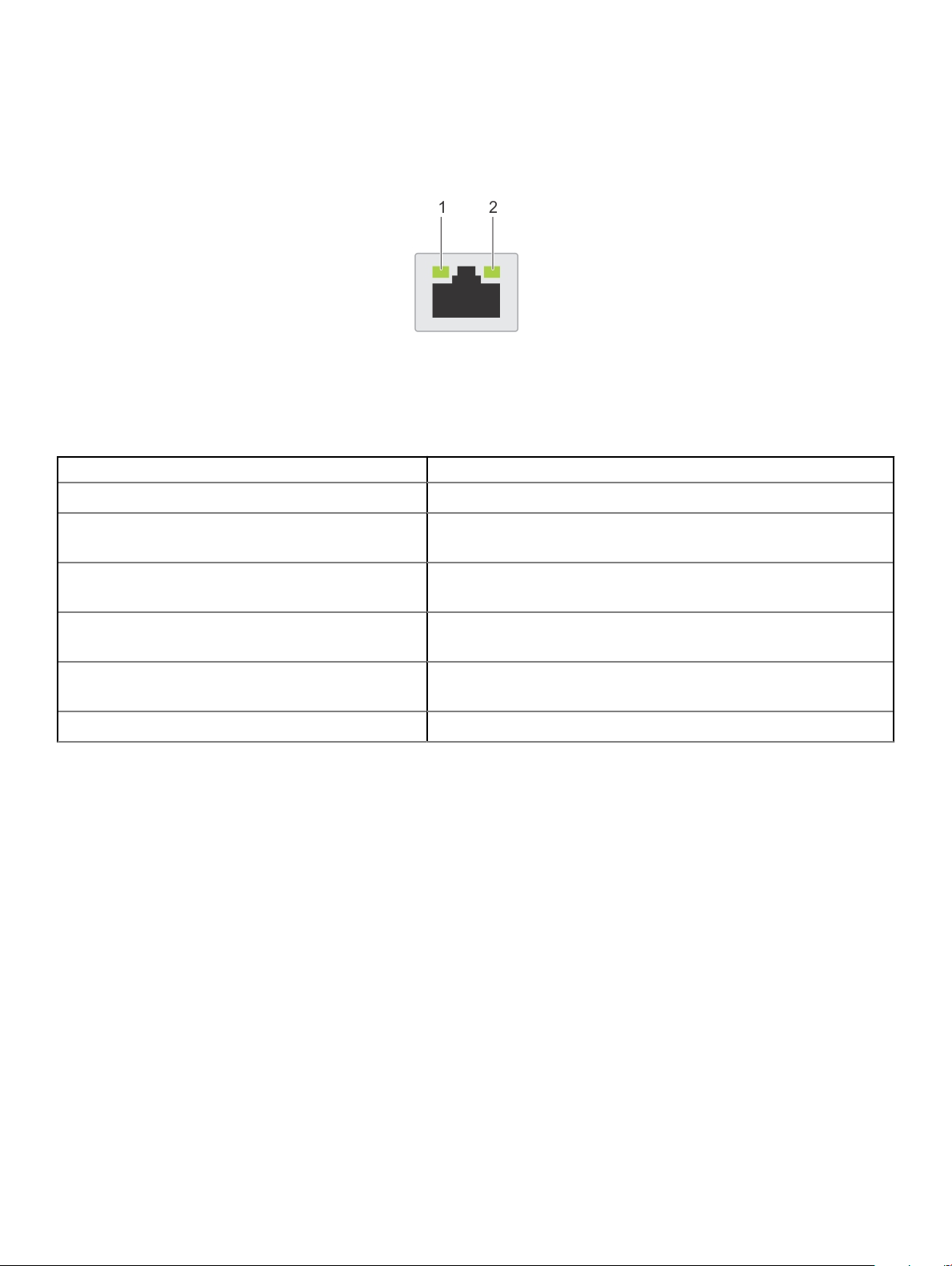
NIC indicator codes
Each NIC on the back of the system has indicators that provide information about the activity and link status. The activity LED indicator
indicates if data is owing through the NIC, and the link LED indicator indicates the speed of the connected network.
Figure 22. NIC indicator codes
1 Link LED indicator 2 Activity LED indicator
Table 27. NIC indicator codes
Status Condition
Link and activity indicators are o. The NIC is not connected to the network.
Link indicator is green, and activity indicator is blinking
green.
Link indicator is amber, and activity indicator is blinking
green.
Link indicator is green, and activity indicator is o. The NIC is connected to a valid network at its maximum port speed, and
Link indicator is amber, and activity indicator is o. The NIC is connected to a valid network at less than its maximum port
Link indicator is blinking green, and activity is o. NIC identify is enabled through the NIC conguration utility.
The NIC is connected to a valid network at its maximum port speed, and
data is being sent or received.
The NIC is connected to a valid network at less than its maximum port
speed, and data is being sent or received.
data is not being sent or received.
speed, and data is not being sent or received.
Power supply unit indicator codes
AC power supply units (PSUs) have an illuminated translucent handle that serves as an indicator.
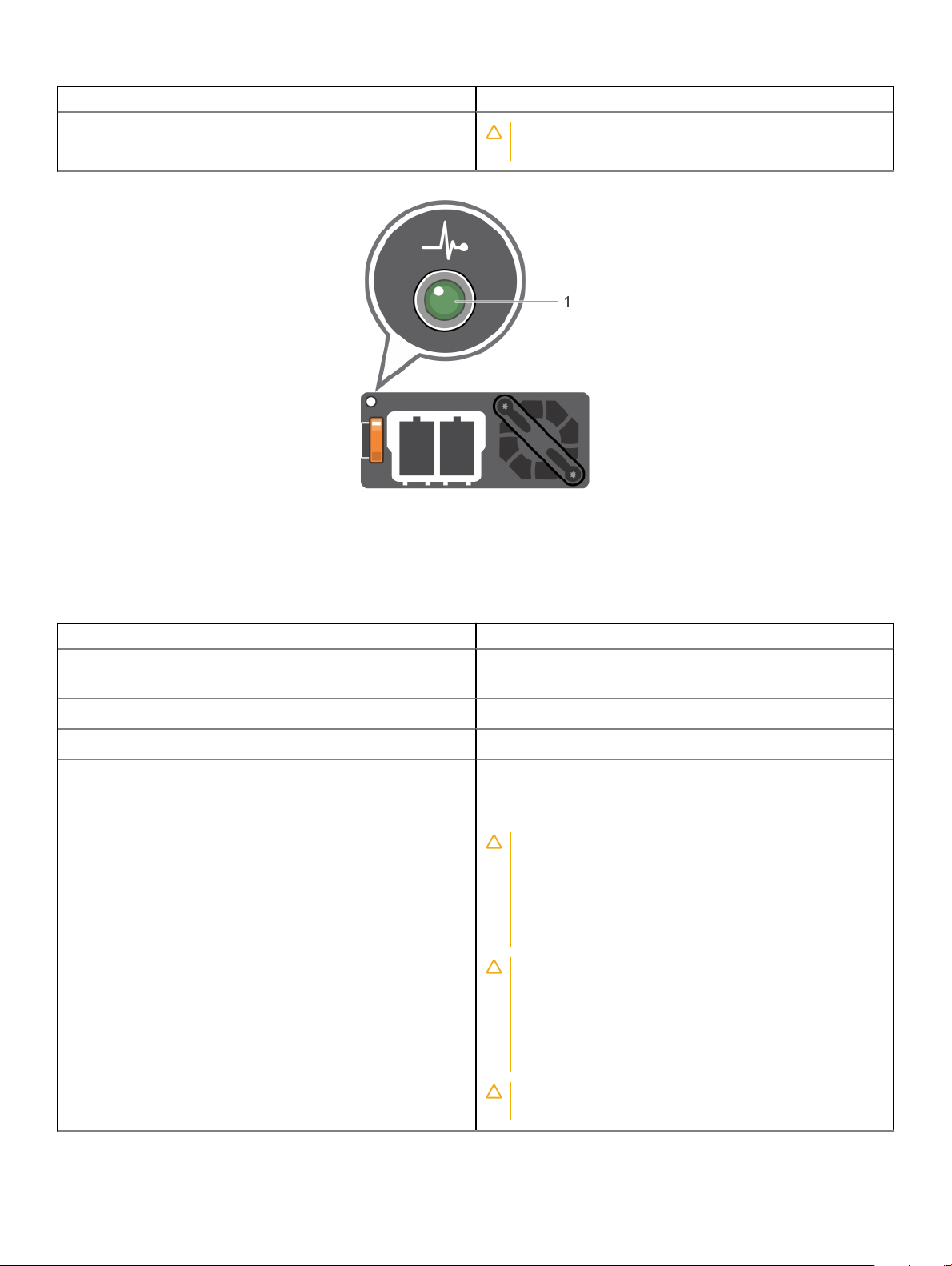
The DC PSUs have an LED that serves as an indicator.
For more information about the PSU specications, see Technical Specications.
For information about the event and error messages generated during POST, when a 2400W PSU is connected to a 110 V power source,
see the Dell Event and Error Messages Reference Guide at www.dell.com/openmanagemanuals.
The indicator shows whether power is present or if a power fault has occurred.
System diagnostics and indicator codes
36
Page 37
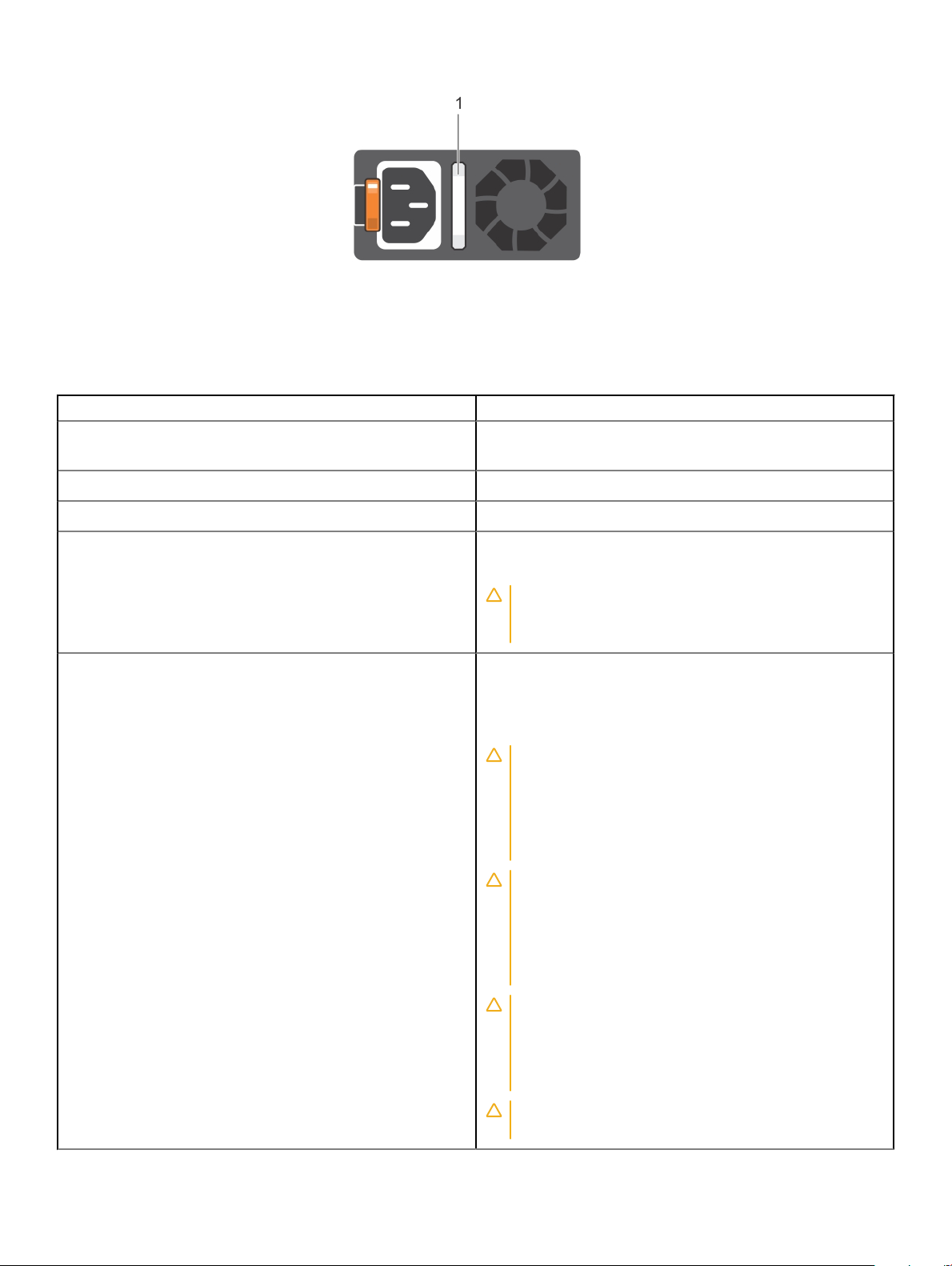
Figure 23. AC PSU status indicator
1 AC PSU status indicator/handle
Table 28. AC PSU status indicator codes
Power indicator codes Condition
Green A valid power source is connected to the PSU, and the PSU is
operational.
Blinking amber Indicates a problem with the PSU.
Not illuminated Power is not connected to the PSU.
Blinking green When the rmware of the PSU is being updated, the PSU handle
blinks green.
CAUTION: Do not disconnect the power cable, or unplug
the PSU when updating rmware. If rmware update is
interrupted, the PSUs do not function.
Blinking green and turns o When hot-plugging a PSU, the PSU handle blinks green ve times
at a rate of 4 Hz and turns o. This indicates a PSU mismatch
concerning eciency, feature set, health status, or supported
voltage.
CAUTION: If two PSUs are installed, both the PSUs must
have the same type of label; for example, Extended Power
Performance (EPP) label. Mixing PSUs from previous
generations of PowerEdge servers is not supported, even
if the PSUs have the same power rating. This results in a
PSU mismatch condition, or failure to turn on the system.
CAUTION: When correcting a PSU mismatch, replace only
the PSU with the blinking indicator. Swapping the PSU to
make a matched pair can result in an error condition and
unexpected system shutdown. To change from a high
output conguration to a low output conguration or
conversely, you must turn o the system.
CAUTION: AC PSUs support both 240 V and 120 V input
voltages except for Titanium PSUs, which support only
240 V. When two identical PSUs receive dierent input
voltages, they can output dierent wattages, and trigger a
mismatch.
CAUTION: If two PSUs are used, they must be of the
same type and have the same maximum output power.
System diagnostics and indicator codes 37
Page 38
Power indicator codes Condition
CAUTION: Combining AC and DC PSUs is not supported
and triggers a mismatch.
Figure 24. DC PSU status indicator
1
DC PSU status indicator
Table 29. DC PSU status indicator codes
Power indicator codes Condition
Green A valid power source is connected to the PSU, and the PSU is
operational.
Blinking amber Indicates a problem with the PSU.
Not illuminated Power is not connected to the PSU.
Blinking green When hot-plugging a PSU, the PSU indicator blinks green. This
indicates that there is a PSU mismatch about eciency, feature set,
health status, or supported voltage.
CAUTION: If two PSUs are installed, both the PSUs must
have the same type of label; for example, Extended Power
Performance (EPP) label. Mixing PSUs from previous
generations of PowerEdge servers is not supported, even
if the PSUs have the same power rating. This results in a
PSU mismatch condition, or failure to turn on the system.
CAUTION: When correcting a PSU mismatch, replace only
the PSU with the blinking indicator. Swapping the PSU to
make a matched pair can result in an error condition and
unexpected system shutdown. To change from a High
Output conguration to a Low Output conguration or
conversely, you must turn o the system.
38 System diagnostics and indicator codes
CAUTION: If two PSUs are used, they must be of the
same type and have the same maximum output power.
Page 39
Power indicator codes Condition
CAUTION: Combining AC and DC PSUs is not supported
and triggers a mismatch.
Drive indicator codes
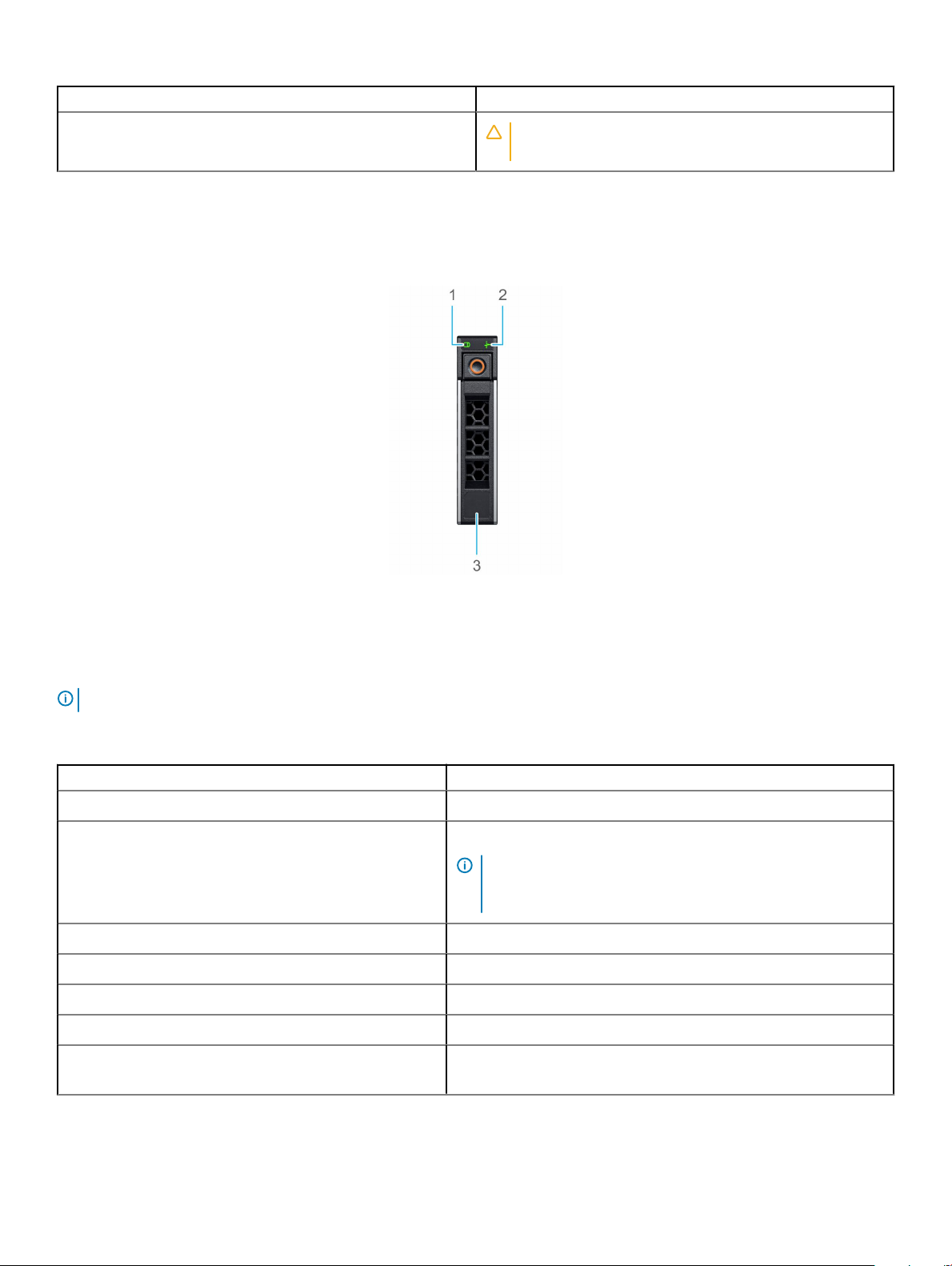
The LEDs on the drive carrier indicates the state of each drive. Each drive carrier in your system has two LEDs: an activity LED (green) and
a status LED (bicolor, green/amber). The activity LED ashes whenever the drive is accessed.
Figure 25. Drive indicators on the drive and the mid drive tray backplane
1
Drive activity LED indicator 2 Drive status LED indicator
3 Drive capacity label
NOTE: If the drive is in the Advanced Host Controller Interface (AHCI) mode, the status LED indicator does not turn on.
Table 30. Drive indicator codes
Drive status indicator code Condition
Flashes green twice per second Identifying drive or preparing for removal.
O Drive ready for removal.
NOTE: The drive status indicator remains o until all drives are
initialized after the system is turned on. Drives are not ready
for removal during this time.
Flashes green, amber, and then turns o Predicted drive failure.
Flashes amber four times per second Drive failed.
Flashes green slowly Drive rebuilding.
Solid green Drive online.
Flashes green for three seconds, amber for three seconds, and
then turns o after six seconds
Rebuild stopped.
System diagnostics and indicator codes 39
Page 40

Using system diagnostics
If you experience a problem with your system, run the system diagnostics before contacting Dell for technical assistance. The purpose of
running system diagnostics is to test your system hardware without using additional equipment or risking data loss. If you are unable to x
the problem yourself, service and support personnel can use the diagnostics results to help you solve the problem.
Dell Embedded System Diagnostics
NOTE: The Dell Embedded System Diagnostics is also known as Enhanced Pre-boot System Assessment (ePSA) diagnostics.
The Embedded System Diagnostics provides a set of options for particular device groups or devices allowing you to:
• Run tests automatically or in an interactive mode
• Repeat tests
• Display or save test results
• Run thorough tests to introduce additional test options to provide extra information about the failed device(s)
• View status messages that inform you if tests are completed successfully
• View error messages that inform you of problems encountered during testing
Running the Embedded System Diagnostics from Boot Manager
Run the Embedded System Diagnostics (ePSA) if your system does not boot.
1 When the system is booting, press F11.
2 Use the up arrow and down arrow keys to select System Utilities > Launch Diagnostics.
3 Alternatively, when the system is booting, press F10, select Hardware Diagnostics > Run Hardware Diagnostics.
The ePSA Pre-boot System Assessment window is displayed, listing all devices detected in the system. The diagnostics starts
executing the tests on all the detected devices.
Running the Embedded System Diagnostics from the Dell Lifecycle
Controller
1 As the system boots, press F10.
2 Select Hardware Diagnostics → Run Hardware Diagnostics.
The ePSA Pre-boot System Assessment window is displayed, listing all devices detected in the system. The diagnostics starts
executing the tests on all the detected devices.
System diagnostic controls
Menu
Conguration Displays the conguration and status information of all detected devices.
Results Displays the results of all tests that are run.
Description
System health Provides the current overview of the system performance.
Event log Displays a time-stamped log of the results of all tests run on the system. This is displayed if at least one event
description is recorded.
40 System diagnostics and indicator codes
Page 41
Documentation resources
This section provides information about the documentation resources for your system.
To view the document that is listed in the documentation resources table:
• From the Dell EMC support site:
a Click the documentation link that is provided in the Location column in the table.
b Click the required product or product version.
NOTE: To locate the product name and model, see the front of your system.
c On the Product Support page, click Manuals & documents.
• Using search engines:
– Type the name and version of the document in the search box.
Table 31. Additional documentation resources for your system
Task Document Location
Setting up your system
For more information about installing and securing
the system into a rack, see the Rail Installation
Guide included with your rack solution.
Dell.com/poweredgemanuals
4
For information about setting up your system, see
the Getting Started Guide document that is
shipped with your system.
Conguring your system For information about the iDRAC features,
conguring and logging in to iDRAC, and managing
your system remotely, see the Integrated Dell
Remote Access Controller User's Guide.
For information about understanding Remote
Access Controller Admin (RACADM)
subcommands and supported RACADM interfaces,
see the RACADM CLI Guide for iDRAC.
For information about Redsh and its protocol,
supported schema, and Redsh Eventing
implemented in iDRAC, see the Redsh API Guide.
For information about iDRAC property database
group and object descriptions, see the Attribute
Registry Guide.
For information about earlier versions of the iDRAC
documents.
To identify the version of iDRAC available on your
system, on the iDRAC web interface, click ? >
About.
Dell.com/poweredgemanuals
Dell.com/idracmanuals
For information about installing the operating
system, see the operating system documentation.
Dell.com/operatingsystemmanuals
Documentation resources 41
Page 42

Task Document Location
For information about updating drivers and
rmware, see the Methods to download rmware
and drivers section in this document.
Managing your system For information about systems management
software oered by Dell, see the Dell OpenManage
Systems Management Overview Guide.
For information about setting up, using, and
troubleshooting OpenManage, see the Dell
OpenManage Server Administrator User’s Guide.
For information about installing, using, and
troubleshooting Dell OpenManage Essentials, see
the Dell OpenManage Essentials User’s Guide.
For information about installing and using Dell
SupportAssist, see the Dell EMC SupportAssist
Enterprise User’s Guide.
For information about partner programs enterprise
systems management, see the OpenManage
Connections Enterprise Systems Management
documents.
Working with the Dell
PowerEdge RAID controllers
For information about understanding the features
of the Dell PowerEdge RAID controllers (PERC),
Software RAID controllers, or BOSS card and
deploying the cards, see the Storage controller
documentation.
Dell.com/support/drivers
Dell.com/poweredgemanuals
Dell.com/openmanagemanuals > OpenManage
Server Administrator
Dell.com/openmanagemanuals > OpenManage
Essentials
Dell.com/serviceabilitytools
Dell.com/openmanagemanuals
Dell.com/storagecontrollermanuals
Understanding event and error
messages
Troubleshooting your system For information about identifying and
For information about the event and error
messages generated by the system rmware and
agents that monitor system components, see the
Error Code Lookup.
troubleshooting the PowerEdge server issues, see
the Server Troubleshooting Guide.
Dell.com/qrl
Dell.com/poweredgemanuals
42 Documentation resources
Page 43

Getting help
Topics:
• Contacting Dell
• Documentation feedback
• Accessing system information by using QRL
• Receiving automated support with SupportAssist
• Recycling or End-of-Life service information
Contacting Dell
Dell provides several online and telephone based support and service options. If you do not have an active internet connection, you can nd
contact information about your purchase invoice, packing slip, bill, or Dell product catalog. Availability varies by country and product, and
some services may not be available in your area. To contact Dell for sales, technical assistance, or customer service issues:
1 Go to Dell.com/support/home
2 Select your country from the drop-down menu on the lower right corner of the page.
3 For customized support:
a Enter your system Service Tag in the Enter your Service Tag eld.
b Click Submit.
The support page that lists the various support categories is displayed.
4 For general support:
a Select your product category.
b Select your product segment.
c Select your product.
The support page that lists the various support categories is displayed.
5 For contact details of Dell Global Technical Support:
a Click Global Technical Support
b The Contact Technical Support page is displayed with details to call, chat, or e-mail the Dell Global Technical Support team.
5
Documentation feedback
You can rate the documentation or write your feedback on any of our Dell EMC documentation pages and click Send Feedback to send
your feedback.
Accessing system information by using QRL
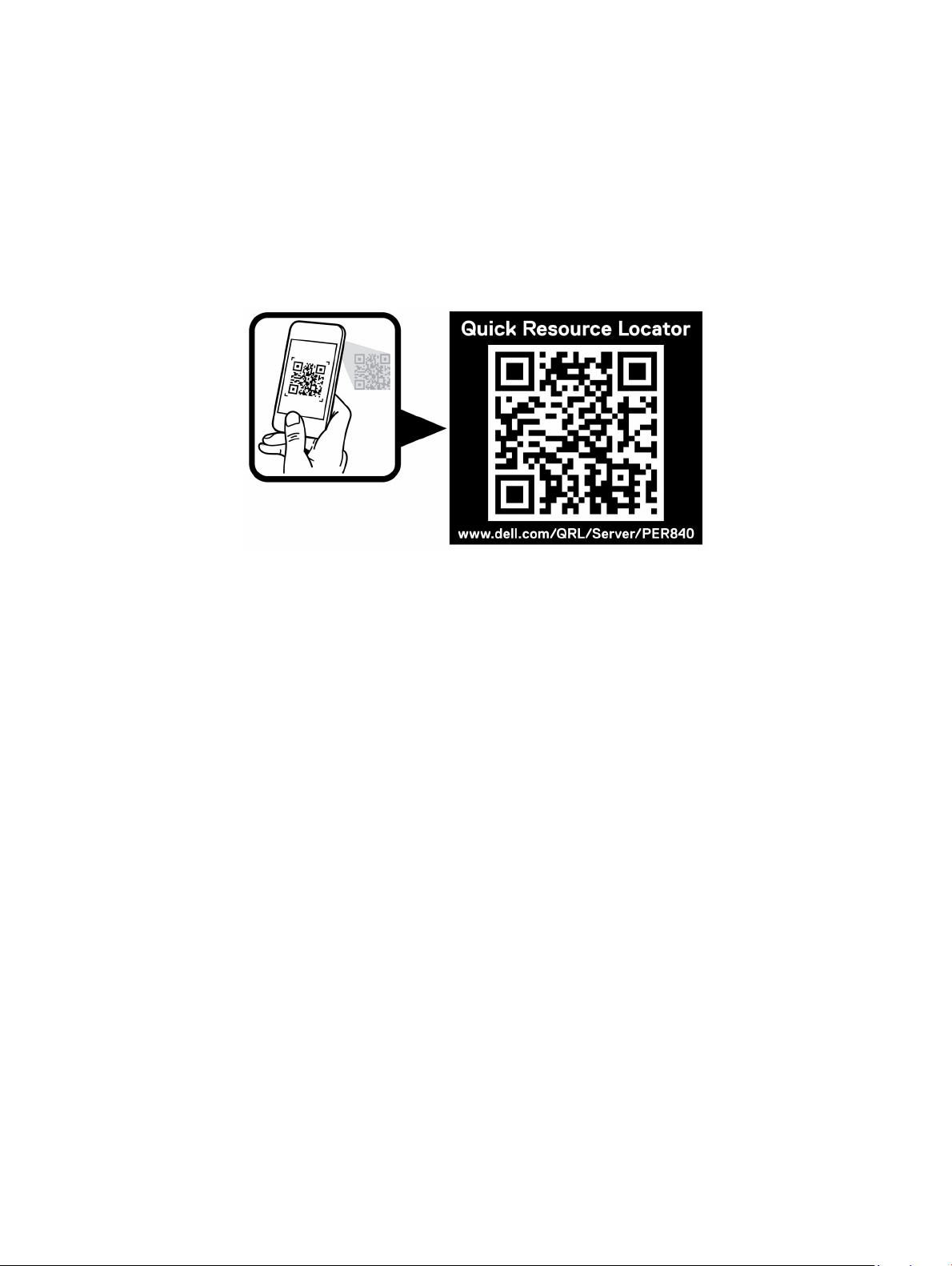
You can use the Quick Resource Locator (QRL) to get immediate access to the information about your system.
Prerequisites
Ensure that your smart phone or tablet has the QR code scanner installed.
The QRL includes the following information about your system:
• How-to videos
• Reference materials, including the Owner’s Manual, LCD diagnostics, and mechanical overview
Getting help 43
Page 44
• Service Tag to quickly access the specic hardware conguration and warranty information
• A direct link to Dell to contact technical support and sales teams
Steps
1 Go to Dell.com/qrl, and navigate to your specic product or
2 Use your smart phone or tablet to scan the model-specic Quick Resource (QR) code on your Dell system or in the Quick Resource
Locator section.
Quick Resource Locator for PowerEdge R840 system
Figure 26. Quick Resource Locator for PowerEdge R840 system
Receiving automated support with SupportAssist
Dell EMC SupportAssist is an optional Dell EMC Services oering that automates technical support for your Dell EMC server, storage, and
networking devices. By installing and setting up a SupportAssist application in your IT environment, you can receive the following benets:
• Automated issue detection — SupportAssist monitors your Dell EMC devices and automatically detects hardware issues, both
proactively and predictively.
• Automated case creation — When an issue is detected, SupportAssist automatically opens a support case with Dell EMC Technical
Support.
• Automated diagnostic collection — SupportAssist automatically collects system state information from your devices and uploads it
securely to Dell EMC. This information is used by Dell EMC Technical Support to troubleshoot the issue.
• Proactive contact — A Dell EMC Technical Support agent contacts you about the support case and helps you resolve the issue.
The available benets vary depending on the Dell EMC Service entitlement purchased for your device. For more information about
SupportAssist, go to Dell.com/supportassist.
Recycling or End-of-Life service information
Take back and recycling services are oered for this product in certain countries. If you want to dispose of system components, visit
Dell.com/recyclingworldwide and select the relevant country.
44
Getting help
 Loading...