

Dell PowerEdge R640 User Manual

Dell EMC PowerEdge R640
Installation and Service Manual
Reg ula tor y M ode l: E39 S S eries
Reg ula tor y T ype : E 39S 001
Jul y 2 020
Rev . A 09

Notes, cautions, and warnings
NOTE: A NOTE indicates important information that helps you make better use of your product.
CAUTION: A CAUTION indicates either potential damage to hardware or loss of data and tells you how to avoid
the problem.
WARNING: A WARNING indicates a potential for property damage, personal injury, or death.
© 2017 - 2020 Dell Inc. or its subsidiaries. All rights reserved . D ell , E MC, and other trademarks are trademarks of Dell Inc. or its subsidi ari es.
Other trademarks may be trademarks of their respective owners.

Contents
Chapter 1: Dell EMC PowerEdge R640 overview.............................................................................7
Supported configurations for PowerEdge R640..........................................................................................................7
Front view of the system...................................................................................................................................................9
Left control panel view............................................................................................................................................... 13
Right control panel view............................................................................................................................................. 15
Back view of the system.................................................................................................................................................. 17
NIC indicator codes..................................................................................................................................................... 21
Power supply unit indicator codes........................................................................................................................... 21
Drive indicator codes........................................................................................................................................................23
LCD panel............................................................................................................................................................................ 24
Viewing Home screen.................................................................................................................................................25
Setup menu...................................................................................................................................................................25
View menu.....................................................................................................................................................................25
Locating the Service Tag of your system................................................................................................................... 26
System information label................................................................................................................................................. 26
Chapter 2: Documentation resources...........................................................................................29
Chapter 3: Initial system setup and configuration........................................................................32
Setting up your system.................................................................................................................................................... 32
iDRAC configuration......................................................................................................................................................... 32
Options to set up iDRAC IP address....................................................................................................................... 32
Log in to iDRAC............................................................................................................................................................33
Options to install the operating system.......................................................................................................................33
Methods to download firmware and drivers......................................................................................................... 33
Downloading drivers and firmware.......................................................................................................................... 34
Chapter 4: Installing and removing system components ............................................................. 35
Safety instructions............................................................................................................................................................35
Before working inside your system............................................................................................................................... 36
After working inside your system.................................................................................................................................. 36
Recommended tools......................................................................................................................................................... 36
Optional front bezel.......................................................................................................................................................... 37
Removing the front bezel.......................................................................................................................................... 37
Installing the front bezel............................................................................................................................................ 37
System cover......................................................................................................................................................................38
Removing the system cover..................................................................................................................................... 38
Installing the system cover....................................................................................................................................... 39
Drives................................................................................................................................................................................... 40
Removing a drive blank.............................................................................................................................................. 40
Installing a drive blank................................................................................................................................................. 41
Removing a drive carrier.............................................................................................................................................41
Installing a drive carrier.............................................................................................................................................. 42
Removing the drive from the drive carrier............................................................................................................ 43
Contents 3

Installing a drive into the drive carrier.................................................................................................................... 44
Backplane cover................................................................................................................................................................ 45
Removing the backplane cover................................................................................................................................45
Installing the backplane cover.................................................................................................................................. 46
Inside the system...............................................................................................................................................................47
Air shroud............................................................................................................................................................................50
Removing the air shroud............................................................................................................................................50
Installing the air shroud..............................................................................................................................................50
Cooling fans.........................................................................................................................................................................51
Removing a cooling fan...............................................................................................................................................51
Installing a cooling fan................................................................................................................................................ 52
System memory................................................................................................................................................................. 53
System memory guidelines........................................................................................................................................ 53
General memory module installation guidelines....................................................................................................54
NVDIMM-N memory module installation guidelines ...........................................................................................55
DCPMM installation guidelines ............................................................................................................................... 59
Mode-specific guidelines........................................................................................................................................... 60
Removing a memory module.....................................................................................................................................63
Installing a memory module....................................................................................................................................... 64
NVDIMM-N battery.......................................................................................................................................................... 65
Removing the NVDIMM-N battery......................................................................................................................... 65
Installing the NVDIMM-N battery........................................................................................................................... 66
Processors and heat sinks...............................................................................................................................................67
Removing a processor and heat sink module........................................................................................................67
Removing the processor from the processor and heat sink module.............................................................. 68
Installing the processor into a processor and heat sink module...................................................................... 69
Installing a processor and heat sink module...........................................................................................................71
Expansion cards and expansion card risers.................................................................................................................72
Expansion bus specifications.................................................................................................................................... 72
Removing an expansion card riser........................................................................................................................... 77
Installing an expansion card riser............................................................................................................................. 79
Removing expansion card from the expansion card riser...................................................................................81
Installing an expansion card into expansion card riser........................................................................................84
M.2 SSD module................................................................................................................................................................ 86
Removing the M.2 SSD module............................................................................................................................... 86
Installing the M.2 SSD module..................................................................................................................................87
Optional IDSDM or vFlash module................................................................................................................................ 88
Removing the optional IDSDM or vFlash card......................................................................................................88
Installing optional IDSDM or vFlash card............................................................................................................... 89
Optional IDSDM or vFlash module................................................................................................................................ 90
Removing the MicroSD card.....................................................................................................................................90
Installing the MicroSD card........................................................................................................................................91
Network daughter card....................................................................................................................................................92
Removing the network daughter card....................................................................................................................92
Installing the network daughter card......................................................................................................................93
Integrated storage controller card................................................................................................................................ 94
Removing the integrated storage controller card............................................................................................... 94
Installing the integrated storage controller card................................................................................................. 95
Backplane............................................................................................................................................................................ 97
Backplane details......................................................................................................................................................... 97
4
Contents

Removing the backplane cover................................................................................................................................98
Installing the backplane..............................................................................................................................................98
Removing the 2.5 inch drive rear backplane........................................................................................................ 99
Installing the 2.5 inch drive rear backplane......................................................................................................... 100
Cable routing.....................................................................................................................................................................102
SAS expander card..........................................................................................................................................................106
Removing the SAS expander card......................................................................................................................... 106
Installing the SAS expander card........................................................................................................................... 107
Rear drive cage................................................................................................................................................................ 108
Removing the rear drive cage.................................................................................................................................108
Installing the rear drive cage...................................................................................................................................109
System battery..................................................................................................................................................................110
Replacing the system battery..................................................................................................................................110
USB module........................................................................................................................................................................ 111
Removing the USB module....................................................................................................................................... 111
Installing the USB module.........................................................................................................................................112
VGA module....................................................................................................................................................................... 112
Removing the VGA module...................................................................................................................................... 112
Installing the VGA module.........................................................................................................................................113
Optional internal USB memory key...............................................................................................................................114
Replacing the optional internal USB memory key...............................................................................................114
Optical drive (optional)................................................................................................................................................... 115
Removing the optical drive.......................................................................................................................................115
Installing the optical drive.........................................................................................................................................115
Power supply units...........................................................................................................................................................116
Hot spare feature........................................................................................................................................................117
Removing a power supply unit blank......................................................................................................................117
Installing a power supply unit blank........................................................................................................................ 117
Removing a power supply unit.................................................................................................................................118
Installing a power supply unit...................................................................................................................................119
Removing a DC power supply unit..........................................................................................................................119
Installing DC power supply unit.............................................................................................................................. 120
Wiring instructions for a DC power supply unit..................................................................................................120
System board.....................................................................................................................................................................121
Removing the system board.................................................................................................................................... 121
Installing the system board...................................................................................................................................... 122
Trusted Platform Module...............................................................................................................................................125
Upgrading the Trusted Platform Module............................................................................................................. 125
Initializing TPM for BitLocker users...................................................................................................................... 126
Initializing the TPM 1.2 for TXT users...................................................................................................................126
Initializing the TPM 2.0 for TXT users.................................................................................................................. 126
Control panel.....................................................................................................................................................................127
Removing the left control panel............................................................................................................................. 127
Installing the left control panel............................................................................................................................... 128
Removing the right control panel...........................................................................................................................129
Installing the right control panel.............................................................................................................................130
Chapter 5: System diagnostics................................................................................................... 131
Dell Embedded System Diagnostics............................................................................................................................. 131
Running the Embedded System Diagnostics from Boot Manager..................................................................131
Contents
5

Running the Embedded System Diagnostics from the Dell Lifecycle Controller.........................................131
System diagnostic controls..................................................................................................................................... 132
Chapter 6: Jumpers and connectors .......................................................................................... 133
System board jumpers and connectors...................................................................................................................... 133
System board jumper settings......................................................................................................................................135
Disabling forgotten password.......................................................................................................................................135
Chapter 7: Getting help..............................................................................................................136
Contacting Dell EMC...................................................................................................................................................... 136
Documentation feedback...............................................................................................................................................136
Accessing system information by using QRL............................................................................................................ 136
Quick Resource Locator for R640......................................................................................................................... 137
Receiving automated support with SupportAssist ................................................................................................. 137
Recycling or End-of-Life service information........................................................................................................... 137
6 Contents

Dell EMC PowerEdge R640 overview
The Dell EMC PowerEdge R640 system is a 1U rack server that supports up to:
● Two 2ndgeneration Intel Xeon Scalable Processors
● 24 DIMM slots
● 8 x 2.5-inch hard drives or 4 x 3.5-inch hard drives on the front panel, or 10 x 2.5-inch hard drives on the front panel with
optional support for 2 X 2.5-inch hard drives on the back panel
● Two AC or DC redundant power supply units
NOTE: All instances of SAS, SATA hard drives, SSDs, NVMe drives are referred to as drives in this document, unless
specified otherwise.
Topics:
• Supported configurations for PowerEdge R640
• Front view of the system
• Back view of the system
• Drive indicator codes
• LCD panel
• Locating the Service Tag of your system
• System information label
1
Supported configurations for PowerEdge R640
The PowerEdge R640 system supports the following configurations:
Dell EMC PowerEdge R640 overview 7
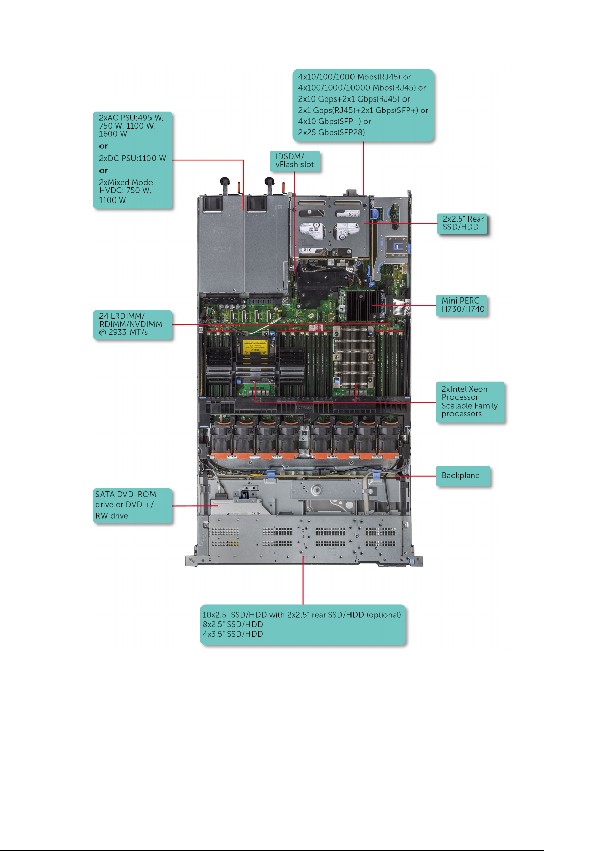
Figure 1. Supported configurations for PowerEdge R640
8
Dell EMC PowerEdge R640 overview

Front view of the system
The front view displays the features available on the front of the system.
Figure 2. Front view of 8 x 2.5-inch drive system
Table 1. Features available on the front of the system
Item Ports, panels, and slots Icon Description
1 Left control panel N/A
Contains the system health
and system ID, status LED,
and the iDRAC Quick Sync 2
(wireless) indicator.
NOTE: The iDRAC Quick
Sync 2 indicator is
available only on certain
configurations.
● Status LED: Enables you
to identify any failed
hardware components.
There are up to five status
LEDs and an overall
system health LED
(Chassis health and
system ID) bar. For more
information, see the
Status LED indicators
section.
● Quick Sync 2 (wireless):
Indicates a Quick Sync
enabled system. The Quick
Sync feature is optional.
This feature allows
management of the
system by using mobile
devices. This feature
aggregates hardware or
firmware inventory and
various system level
diagnostic and error
information that can be
used in troubleshooting
the system. For more
information, see the
Integrated Dell Remote
Access Controller User’s
Guide at www.dell.com/
poweredgemanuals.
2
Optical drive (optional) N/A One optional slim SATA DVD-
ROM drive or DVD+/-RW
drive.
Dell EMC PowerEdge R640 overview 9

Table 1. Features available on the front of the system (continued)
Item Ports, panels, and slots Icon Description
NOTE: DVD devices are
data only.
3 USB port (optional)
4 VGA port Enables you to connect a
5 Right control panel N/A Contains the power button,
6 Drive slots N/A
The USB port is USB 3.0
compliant.
display device to the system.
For more information, see the
www.dell.com/
poweredgemanuals section.
USB port, iDRAC Direct micro
port, and the iDRAC Direct
status LED.
Enable you to install drives
that are supported on your
system. For more information
about drives, see the
www.dell.com/
poweredgemanuals section.
Figure 3. Front view of 4 x 3.5-inch drive system
Table 2. Features available on the front of the system
Item Ports, panels, and slots Icon Description
1 Left control panel N/A
Contains the system health
and system ID, status LED,
and the iDRAC Quick Sync 2
(wireless) indicator.
NOTE: The iDRAC Quick
Sync 2 indicator is
available only on certain
configurations.
● Status LED: Enables you
to identify any failed
hardware components.
There are up to five status
LEDs and an overall
system health LED
(Chassis health and
system ID) bar. For more
information, see the
Status LED indicators
section.
● Quick Sync 2 (wireless):
Indicates a Quick Sync
10 Dell EMC PowerEdge R640 overview

Table 2. Features available on the front of the system (continued)
Item Ports, panels, and slots Icon Description
enabled system. The Quick
Sync feature is optional.
This feature allows
management of the
system by using mobile
devices. This feature
aggregates hardware or
firmware inventory and
various system level
diagnostic and error
information that can be
used in troubleshooting
the system. For more
information, see the
Integrated Dell Remote
Access Controller User’s
Guide at www.dell.com/
poweredgemanuals.
2 Drive slots N/A Enable you to install drives
that are supported on your
system. For more information
about drives, see the
www.dell.com/
poweredgemanuals section.
3 Optical drive (optional) N/A One optional slim SATA DVD-
ROM drive or DVD+/-RW
drive.
NOTE: DVD devices are
data only.
4 VGA port Enables you to connect a
display device to the system.
For more information, see the
www.dell.com/
poweredgemanuals section.
5 USB port (optional)
6 Right control panel N/A Contains the power button,
7 Information tag N/A
The USB port is USB 3.0
compliant.
USB port, iDRAC Direct micro
port, and the iDRAC Direct
status LED.
The Information Tag is a slideout label panel that contains
system information such as
Service Tag, NIC, MAC
address, and so on. If you
have opted for the secure
default access to iDRAC, the
Information tag also contains
the iDRAC secure default
password.
Dell EMC PowerEdge R640 overview 11

Figure 4. Front view of 10 x 2.5-inch drive system
Table 3. Features available on the front of the system
Item Ports, panels, and
slots
1 Left control panel N/A
2 Drive slots N/A
3 VGA port Enables you to connect a display device to the system. For more
4 Right control panel N/A Contains the power button, USB port, iDRAC Direct micro port,
Icon Description
Contains the system health and system ID, status LED, and the
iDRAC Quick Sync 2 (wireless) indicator.
NOTE: The iDRAC Quick Sync 2 indicator is available only
on certain configurations.
● Status LED: Enables you to identify any failed hardware
components. There are up to five status LEDs and an overall
system health LED (Chassis health and system ID) bar. For
more information, see the Status LED indicators section.
● Quick Sync 2 (wireless): Indicates a Quick Sync enabled
system. The Quick Sync feature is optional. This feature
allows management of the system by using mobile devices.
This feature aggregates hardware or firmware inventory and
various system level diagnostic and error information that
can be used in troubleshooting the system. For more
information, see the Integrated Dell Remote Access
Controller User’s Guide at www.dell.com/
poweredgemanuals.
Enable you to install drives that are supported on your system.
For more information about drives, see the Technical
specifications section.
information, see the www.dell.com/poweredgemanuals section.
and the iDRAC Direct status LED.
5 Information tag N/A
12 Dell EMC PowerEdge R640 overview
The Information Tag is a slide-out label panel that contains
system information such as Service Tag, NIC, MAC address, and
so on. If you have opted for the secure default access to iDRAC,
the Information tag also contains the iDRAC secure default
password.

Left control panel view
Figure 5. Left control panel with optional iDRAC Quick Sync 2.0 indicator
Table 4. Left control panel
Item Indicator or button Icon Description
1 Status LED indicators N/A Indicate the status of the system. For more information, see the
Status LED indicators section.
2
System health and system
ID indicator
Indicates the system health. For more information, see the
System health and system ID indicator codes section.
3 iDRAC Quick Sync 2
wireless indicator
(optional)
NOTE: iDRAC Quick
Sync 2 wireless
indicator is available
only on certain
configurations.
Indicates if the iDRAC Quick Sync 2 wireless option is activated.
The Quick Sync 2 feature allows management of the system
using mobile devices. This feature aggregates hardware/
firmware inventory and various system level diagnostic/error
information that can be used in troubleshooting the system.
You can access system inventory, Dell EMC Lifecycle Controller
logs or system logs, system health status, and also configure
iDRAC, BIOS, and networking parameters. You can also launch
the virtual Keyboard, Video, and Mouse (KVM) viewer and
virtual Kernel based Virtual Machine (KVM), on a supported
mobile device.www.dell.com/poweredgemanuals
Status LED indicators
NOTE: The indicators display solid amber if any error occurs.
Table 5. Status LED indicators and descriptions
Icon Description Condition Corrective action
Drive
indicator
The indicator turns solid amber if
there is a drive error.
● Check the System Event Log to determine if the drive has an
error.
● Run the appropriate Online Diagnostics test. Restart the system
and run embedded diagnostics (ePSA).
● If the drives are configured in a RAID array, restart the system,
and enter the host adapter configuration utility program.
Temperature
indicator
The indicator turns solid amber if
the system experiences a
thermal error (for example, the
ambient temperature is out of
range or there is a fan failure).
Ensure that none of the following conditions exist:
● A cooling fan has been removed or has failed.
● System cover, air shroud, memory module blank, or back filler
bracket is removed.
Dell EMC PowerEdge R640 overview 13
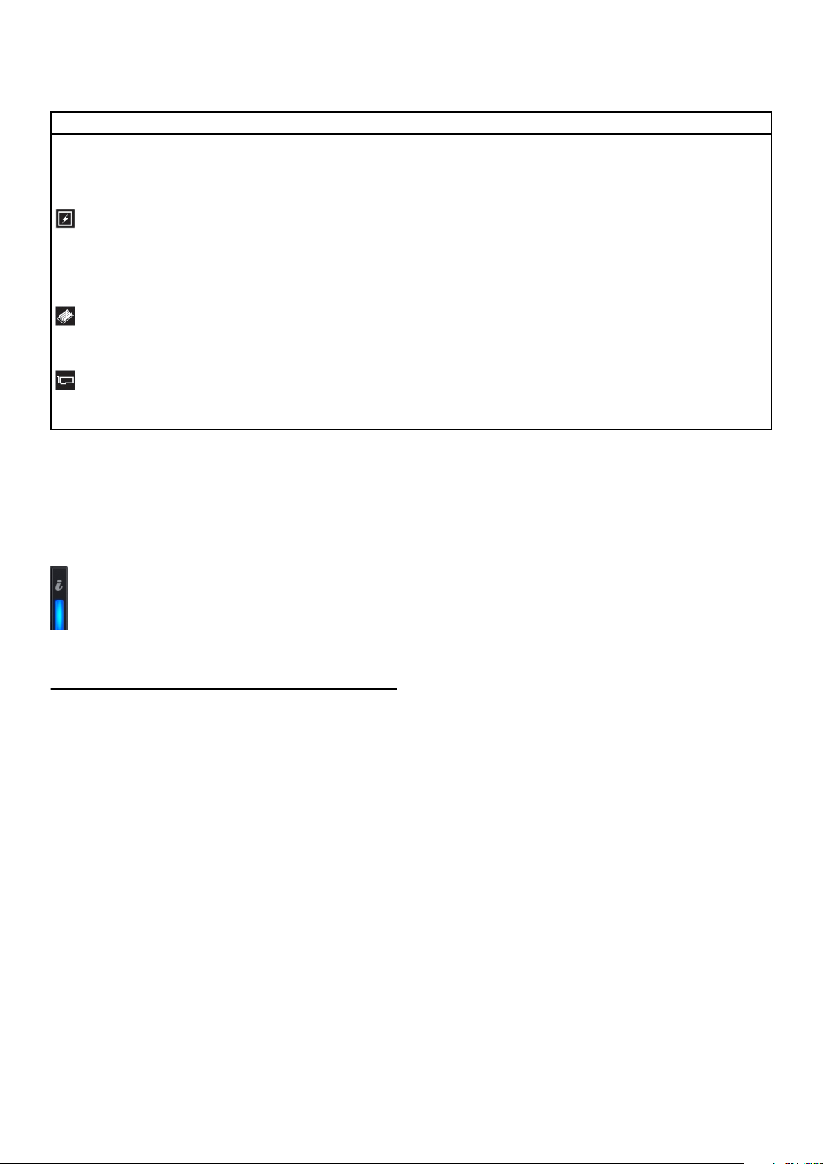
Table 5. Status LED indicators and descriptions (continued)
Icon Description Condition Corrective action
● Ambient temperature is too high.
● External airflow is obstructed.
If the problem persists, see Getting help.
Electrical
indicator
Memory
indicator
PCIe
indicator
The indicator turns solid amber if
the system experiences an
electrical error (for example,
voltage out of range, or a failed
power supply unit (PSU) or
voltage regulator).
The indicator turns solid amber if
a memory error occurs.
The indicator turns solid amber if
a PCIe card experiences an
error.
Check the System Event Log or system messages for the specific
issue. If it is due to a problem with the PSU, check the LED on the
PSU. Reseat the PSU.
If the problem persists, see Getting help.
Check the System Event Log or system messages for the location of
the failed memory. Reseat the memory module.
If the problem persists, see Getting help.
Restart the system. Update any required drivers for the PCIe card.
Reinstall the card.
If the problem persists, see Getting help.
System health and system ID indicator codes
The system health and system ID indicator is located on the left control panel of your system.
System health and system ID indicators
Table 6. System health and system ID indicator codes
System health and system ID indicator code Condition
Solid blue
Blinking blue Indicates that the system ID mode is active. Press the system
Solid amber Indicates that the system is in fail-safe mode. If the problem
Blinking amber Indicates that the system is experiencing a fault. Check the
Indicates that the system is turned on, system is healthy, and
system ID mode is not active. Press the system health and
system ID button to switch to system ID mode.
health and system ID button to switch to system health mode.
persists, see the Getting help section.
System Event Log or the LCD panel, if available on the bezel, for
specific error messages. For information about the event and
error messages generated by the system firmware and agents
that monitor system components, go to qrl.dell.com > Look Up >
Error Code, type the error code, and then click Look it up..
14 Dell EMC PowerEdge R640 overview

iDRAC Quick Sync 2 indicator codes
iDRAC Quick Sync 2 module (optional) is located on the left control panel of your system.
iDRAC Quick Sync 2 indicators
Table 7. iDRAC Quick Sync 2 indicators and descriptions
iDRAC Quick Sync 2 indicator
code
Off (default state) Indicates that the iDRAC Quick Sync 2
Solid white Indicates that iDRAC Quick Sync 2 is
Blinks white rapidly Indicates data transfer activity.
Condition Corrective action
If the LED fails to turn on, reseat the left control
feature is turned off. Press the iDRAC
Quick Sync 2 button to turn on the
iDRAC Quick Sync 2 feature.
ready to communicate. Press the iDRAC
Quick Sync 2 button to turn off.
panel flex cable and check. If the problem
persists, see the Getting help section.
If the LED fails to turn off, restart the system. If
the problem persists, see the Getting help
section.
If the indicator continues to blink indefinitely, see
the Getting help section.
Blinks white slowly Indicates that firmware update is in
progress.
Blinks white five times rapidly
and then turns off
Solid amber Indicates that the system is in fail-safe
Blinking amber Indicates that the iDRAC Quick Sync 2
Indicates that the iDRAC Quick Sync 2
feature is disabled.
mode.
hardware is not responding properly.
Right control panel view
If the indicator continues to blink indefinitely, see
the Getting help section.
Check if iDRAC Quick Sync 2 feature is
configured to be disabled by iDRAC. If the
problem persists, see the Getting help section.
www.dell.com/poweredgemanuals or Dell
OpenManage Server Administrator User’s Guide
at https://www.dell.com/openmanagemanuals.
Restart the system. If the problem persists, see
the Getting help section.
Restart the system. If the problem persists, see
the Getting help section.
Figure 6. Right control panel
Dell EMC PowerEdge R640 overview
15
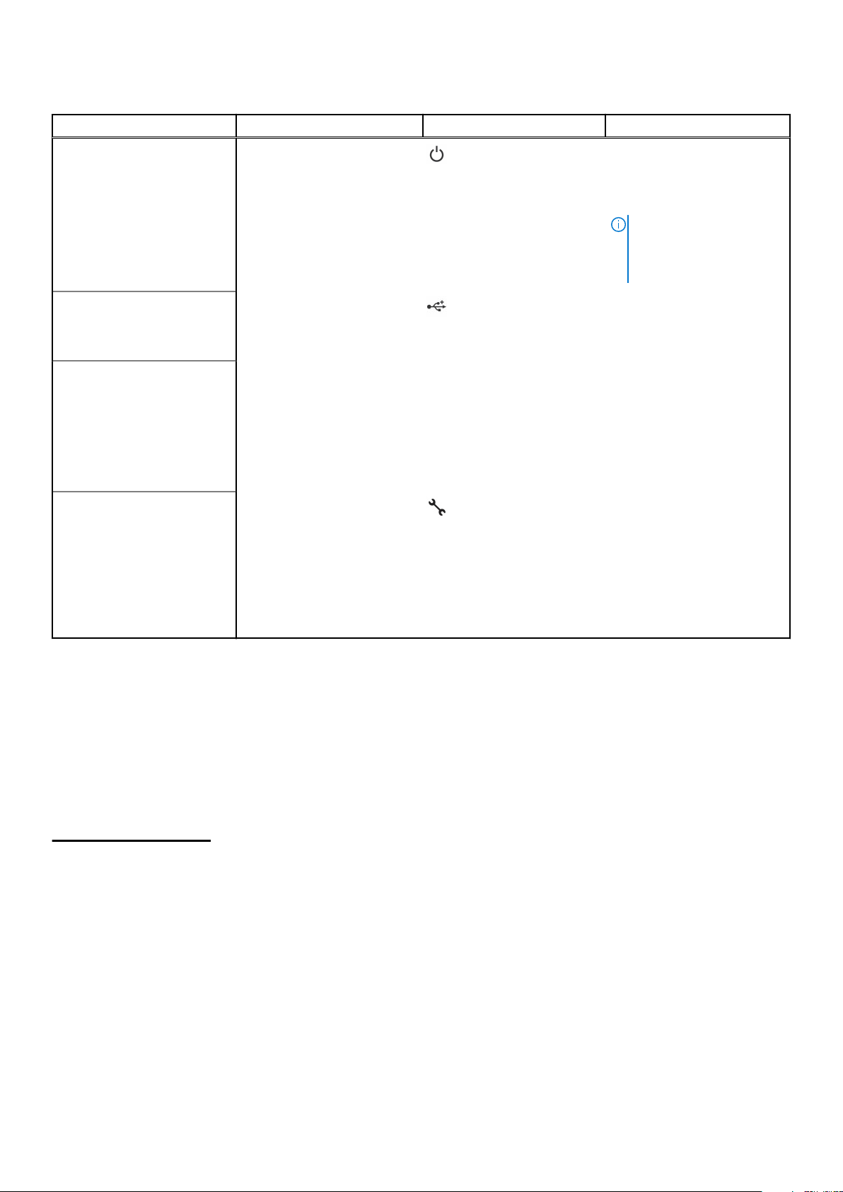
Table 8. Right control panel
Item Indicator or button Icon Description
1 Power button
2
3
4
USB port The USB ports are 4-pin, 2.0-
iDRAC Direct LED N/A The iDRAC Direct LED
iDRAC Direct port (Micro-AB
USB)
Indicates if the system is
powered on or off. Press the
power button to manually
power on or off the system.
NOTE: Press the power
button to gracefully shut
down an ACPI-compliant
operating system.
compliant. This port enables
you to connect USB devices
to the system.
indicator lights up to indicate
that the iDRAC Direct port is
actively connected to a
device. For more information,
see the iDRAC Quick Sync 2
indicator codes on page 15
section.
The iDRAC Direct (Micro-AB
USB) port enables you to
access the iDRAC Direct
(Micro-AB) features. For
more information, see the
Integrated Dell Remote
Access Controller User’s
Guide at www.dell.com/
poweredgemanuals.
iDRAC Direct LED indicator codes
The iDRAC Direct LED indicator lights up to indicate that the port is connected and is being used as a part of the iDRAC
subsystem.
You can configure iDRAC Direct by using a USB to micro USB (type AB) cable, which you can connect to your laptop or tablet.
The following table describes iDRAC Direct activity when the iDRAC Direct port is active:
Table 9. iDRAC Direct LED indicator codes
iDRAC Direct LED
indicator code
Solid green for two
seconds
Flashing green (on for
two seconds and off for
two seconds)
Turns off Indicates that the laptop or tablet is unplugged.
Condition
Indicates that the laptop or tablet is connected.
Indicates that the laptop or tablet connected is recognized.
16 Dell EMC PowerEdge R640 overview

Back view of the system
The back view displays the features available on the back of the system.
Figure 7. Back view of 2 x 2.5-inch drives with 1 PCIe expansion slot
Table 10. 2 X 2.5-inch drive system with 1 PCIe expansion slot
Item Ports, panels, or slots Icon Description
1 PCIe expansion card slot N/A
2 Drive slot (2) N/A Enable you to install drives
The expansion slot(s) enable
you to connect PCI Express
expansion cards. For more
information on the expansion
cards that are supported on
your system, see the
Expansion card guidelines.
that are supported on your
system. For more information
about drives, see the
www.dell.com/
poweredgemanuals section.
3
4 NIC port (4) The NIC ports that are
5 USB 3.0 port (2)
6 VGA port Enables you to connect a
7 Serial port Enables you to connect a
Power supply unit (2) N/A For more information about
the PSU configurations, see
the www.dell.com/
poweredgemanuals section
integrated on the network
daughter card (NDC) provide
network connectivity. For
more information about the
supported configurations, see
the www.dell.com/
poweredgemanuals section.
The USB ports are 9-pin and
3.0-compliant. These ports
enable you to connect USB
devices to the system.
display device to the system.
For more information, see the
www.dell.com/
poweredgemanuals section.
serial device to the system.
For more information, see the
www.dell.com/
poweredgemanuals section.
Dell EMC PowerEdge R640 overview 17

Table 10. 2 X 2.5-inch drive system with 1 PCIe expansion slot (continued)
Item Ports, panels, or slots Icon Description
8 iDRAC9 dedicated network
port
9 System status indicator cable
port
10 System identification button
N/A Enables you to connect the
Use the iDRAC9 dedicated
network port to securely
access the embedded iDRAC
on a separate management
network, see the Integrated
Dell Remote Access Controller
User’s Guide at
www.dell.com/
poweredgemanuals
status indicator cable and
view system status when the
CMA is installed.
The System Identification (ID)
button is available on the
front and back of the
systems. Press the button to
identify a system in a rack by
turning on the system ID
button. You can also use the
system ID button to reset
iDRAC and to access BIOS
using the step through mode.
Figure 8. Back view of system with 3 PCIe expansion slots
Table 11. 2 X 2.5-inch drive system with 3 PCIe expansion slot
Item Ports, panels, or slots Icon Description
1 PCIe expansion card slot(3) N/A
2 Power supply unit (2) N/A For more information about
3 NIC port (4) The NIC ports that are
The expansion slot(s) enable
you to connect PCI Express
expansion cards. For more
information on the expansion
cards that are supported on
your system, see the
Expansion card guidelines.
the PSU configurations, see
the www.dell.com/
poweredgemanuals section
integrated on the network
daughter card (NDC) provide
network connectivity. For
more information about the
supported configurations, see
the www.dell.com/
poweredgemanuals section.
18 Dell EMC PowerEdge R640 overview

Table 11. 2 X 2.5-inch drive system with 3 PCIe expansion slot (continued)
Item Ports, panels, or slots Icon Description
4 USB 3.0 port (2)
5 VGA port Enables you to connect a
6 Serial port Enables you to connect a
7 iDRAC9 dedicated network
port
8 System status indicator cable
port
9 System identification button
N/A Enables you to connect the
The USB ports are 9-pin and
3.0-compliant. These ports
enable you to connect USB
devices to the system.
display device to the system.
For more information, see the
www.dell.com/
poweredgemanuals section.
serial device to the system.
For more information, see the
www.dell.com/
poweredgemanuals section.
Use the iDRAC9 dedicated
network port to securely
access the embedded iDRAC
on a separate management
network, see the
www.dell.com/
poweredgemanuals
status indicator cable and
view system status when the
CMA is installed.
The System Identification (ID)
button is available on the
front and back of the
systems. Press the button to
identify a system in a rack by
turning on the system ID
button. You can also use the
system ID button to reset
iDRAC and to access BIOS
using the step through mode.
Figure 9. Back view of system with 2 PCIe expansion slots
Table 12. 2 X 2.5-inch drive system with 2 PCIe expansion slot
Item Ports, panels, or slots Icon Description
1 PCIe expansion card slot (2) N/A
Dell EMC PowerEdge R640 overview 19
The expansion slot(s) enable
you to connect PCI Express
expansion cards. For more
information on the expansion
cards that are supported on

Table 12. 2 X 2.5-inch drive system with 2 PCIe expansion slot (continued)
Item Ports, panels, or slots Icon Description
your system, see the
Expansion card guidelines.
2 Power supply unit (2) N/A For more information about
the PSU configurations, see
the Technical specifications
section
3 NIC port (4) The NIC ports that are
integrated on the network
daughter card (NDC) provide
network connectivity. For
more information about the
supported configurations, see
the www.dell.com/
poweredgemanuals section.
4 USB 3.0 port (2)
5 VGA port Enables you to connect a
6 Serial port Enables you to connect a
7 iDRAC9 dedicated network
port
8 System status indicator cable
port
9 System identification button
N/A Enables you to connect the
The USB ports are 9-pin and
3.0-compliant. These ports
enable you to connect USB
devices to the system.
display device to the system.
For more information, see the
www.dell.com/
poweredgemanuals section.
serial device to the system.
For more information, see the
www.dell.com/
poweredgemanuals section.
Use the iDRAC9 dedicated
network port to securely
access the embedded iDRAC
on a separate management
network, see the
www.dell.com/
poweredgemanuals
status indicator cable and
view system status when the
CMA is installed.
The System Identification (ID)
button is available on the
front and back of the
systems. Press the button to
identify a system in a rack by
turning on the system ID
button. You can also use the
system ID button to reset
iDRAC and to access BIOS
using the step through mode.
20 Dell EMC PowerEdge R640 overview

NIC indicator codes
Each NIC on the back of the system has indicators that provide information about the activity and link status. The activity LED
indicator indicates if data is flowing through the NIC, and the link LED indicator indicates the speed of the connected network.
Figure 10. NIC indicator codes
1. Link LED indicator
2. Activity LED indicator
Table 13. NIC indicator codes
Status Condition
Link and activity indicators are off. The NIC is not connected to the network.
Link indicator is green, and activity indicator is blinking
green.
Link indicator is amber, and activity indicator is blinking
green.
Link indicator is green, and activity indicator is off. The NIC is connected to a valid network at its maximum port speed,
Link indicator is amber, and activity indicator is off. The NIC is connected to a valid network at less than its maximum
Link indicator is blinking green, and activity is off. NIC identify is enabled through the NIC configuration utility.
The NIC is connected to a valid network at its maximum port speed,
and data is being sent or received.
The NIC is connected to a valid network at less than its maximum
port speed, and data is being sent or received.
and data is not being sent or received.
port speed, and data is not being sent or received.
Power supply unit indicator codes
AC power supply units (PSUs) have an illuminated translucent handle that serves as an indicator. The DC PSUs have an LED
that serves as an indicator. The indicator shows whether power is present or if a power fault has occurred.
Figure 11. AC PSU status indicator
1. AC PSU status indicator/handle
Table 14. AC PSU status indicator codes
Power indicator codes Condition
Green A valid power source is connected to the PSU and the PSU is operational.
Blinking amber Indicates a problem with the PSU.
Not illuminated Power is not connected to the PSU.
Dell EMC PowerEdge R640 overview 21

Table 14. AC PSU status indicator codes (continued)
Power indicator codes Condition
Blinking green When the firmware of the PSU is being updated, the PSU handle blinks green.
CAUTION: Do not disconnect the power cord or unplug the PSU when updating
firmware. If firmware update is interrupted, the PSUs do not function.
Blinking green and turns
off
When hot-plugging a PSU, the PSU handle blinks green five times at a rate of 4 Hz and turns off.
This indicates a PSU mismatch with respect to efficiency, feature set, health status, or supported
voltage. If two PSUs are installed, both the PSUs must have the same type of label; for example,
Extended Power Performance (EPP) label. Mixing PSUs from previous generations of PowerEdge
servers is not supported, even if the PSUs have the same power rating. This results in a PSU
mismatch condition or failure to turn the system on.
CAUTION: When correcting a PSU mismatch, replace only the PSU with the blinking
indicator. Swapping the PSU to make a matched pair can result in an error condition
and unexpected system shutdown. To change from a high output configuration to a
low output configuration or vice versa, you must turn off the system. AC PSUs
support both 240 V and 120 V input voltages with the exception of Titanium PSUs,
which support only 240 V. When two identical PSUs receive different input voltages,
they can output different wattages, and trigger a mismatch.
CAUTION: If two PSUs are used, they must be of the same type and have the same
maximum output power. Combining AC and DC PSUs is not supported and triggers a
mismatch.
DC PSU status indicator
1. DC PSU status indicator
Table 15. DC PSU status indicator codes
Power indicator codes Condition
Green
Blinking amber Indicates a problem with the PSU.
Not illuminated Power is not connected to the PSU.
Blinking green When hot-plugging a PSU, the PSU indicator blinks green. This indicates that there is a PSU
22 Dell EMC PowerEdge R640 overview
A valid power source is connected to the PSU and the PSU is operational.
mismatch with respect to efficiency, feature set, health status, or supported voltage.
CAUTION: If two PSUs are installed, both the PSUs must have the same type of
label; for example, Extended Power Performance (EPP) label. Mixing PSUs from
previous generations of PowerEdge servers is not supported, even if the PSUs
Table 15. DC PSU status indicator codes (continued)
Power indicator codes Condition
have the same power rating. This results in a PSU mismatch condition or failure to
turn the system on.
CAUTION: When correcting a PSU mismatch, replace only the PSU with the
blinking indicator. Swapping the PSU to make a matched pair can result in an error
condition and unexpected system shutdown. To change from a High Output
configuration to a Low Output configuration or vice versa, you must turn off the
system.
CAUTION: If two PSUs are used, they must be of the same type and have the same
maximum output power.
CAUTION: Combining AC and DC PSUs is not supported and triggers a mismatch.
Drive indicator codes
Each drive carrier has an activity LED indicator and a status LED indicator. The indicators provide information about the current
status of the drive. The activity LED indicator indicates whether the drive is currently in use or not. The status LED indicator
indicates the power condition of the drive.
Figure 12. Drive indicators on the drive and the mid drive tray backplane
1. Drive activity LED indicator
2. Drive status LED indicator
3. Drive capacity label
NOTE: If the drive is in the Advanced Host Controller Interface (AHCI) mode, the status LED indicator does not turn on.
Table 16. Drive indicator codes
Drive status indicator code Condition
Flashes green twice per second Identifying drive or preparing for removal.
Off Drive ready for removal.
NOTE: The drive status indicator remains off until all drives
are initialized after the system is turned on. Drives are not
ready for removal during this time.
Flashes green, amber, and then turns off Predicted drive failure.
Flashes amber four times per second Drive failed.
Flashes green slowly Drive rebuilding.
Dell EMC PowerEdge R640 overview 23

Table 16. Drive indicator codes (continued)
Drive status indicator code Condition
Solid green Drive online.
Flashes green for three seconds, amber for three
seconds, and then turns off after six seconds
Rebuild stopped.
LCD panel
The LCD panel provides system information, status, and error messages to indicate if the system is functioning correctly or
requires attention. The LCD panel can also be used to configure or view the system’s iDRAC IP address. For information about
the event and error messages generated by the system firmware and agents that monitor system components, go to
qrl.dell.com > Look Up > Error Code, type the error code, and then click Look it up..
The LCD panel is available only on the optional front bezel. The optional front bezel is hot pluggable.
The statuses and conditions of the LCD panel are outlined here:
● The LCD backlight is white during normal operating conditions.
● When the system needs attention, the LCD backlight turns amber, and displays an error code followed by descriptive text.
NOTE: If the system is connected to a power source and an error is detected, the LCD turns amber regardless of
whether the system is turned on or off.
● When the system turns off and there are no errors, LCD enters the standby mode after five minutes of inactivity. Press any
button on the LCD to turn it on.
● If the LCD panel stops responding, remove the bezel and reinstall it.
If the problem persists, see Getting help.
● The LCD backlight remains off if LCD messaging is turned off using the iDRAC utility, the LCD panel, or other tools.
Figure 13. LCD panel features
Table 17. LCD panel features
Item Button or
display
1 Left Moves the cursor back in one-step increments.
2 Select Selects the menu item highlighted by the cursor.
3 Right Moves the cursor forward in one-step increments.
4 LCD display Displays system information, status, and error messages or iDRAC IP address.
Description
During message scrolling:
● Press and hold the right button to increase scrolling speed.
● Release the button to stop.
NOTE: The display stops scrolling when the button is released. After 45 seconds of inactivity,
the display starts scrolling.
24 Dell EMC PowerEdge R640 overview

Viewing Home screen
The Home screen displays user-configurable information about the system. This screen is displayed during normal system
operation when there are no status messages or errors. When the system turns off and there are no errors, LCD enters the
standby mode after five minutes of inactivity. Press any button on the LCD to turn it on.
Steps
1. To view the Home screen, press one of the three navigation buttons (Select, Left, or Right).
2. To navigate to the Home screen from another menu, complete the following steps:
a. Press and hold the navigation button until the up arrow
Navigate to the Home icon
b.
c. Select the Home icon.
d. On the Home screen, press the Select button to enter the main menu.
using the up arrow .
is displayed.
Setup menu
NOTE: When you select an option in the Setup menu, you must confirm the option before proceeding to the next action.
Option Description
iDRAC Select DHCP or Static IP to configure the network mode. If Static IP is selected, the available fields are
IP, Subnet (Sub), and Gateway (Gtw). Select Setup DNS to enable DNS and to view domain
addresses. Two separate DNS entries are available.
Set error Select SEL to view LCD error messages in a format that matches the IPMI description in the SEL. This
enables you to match an LCD message with an SEL entry.
Select Simple to view LCD error messages in a simplified user-friendly description. For information about
the event and error messages generated by the system firmware and agents that monitor system
components, go to qrl.dell.com > Look Up > Error Code, type the error code, and then click Look it up.
Set home Select the default information to be displayed on the Home screen. See View menu section for the
options and option items that can be set as the default on the Home screen.
View menu
NOTE: When you select an option in the View menu, you must confirm the option before proceeding to the next action.
Option Description
iDRAC IP Displays the IPv4 or IPv6 addresses for iDRAC9. Addresses include DNS (Primary and Secondary),
Gateway, IP, and Subnet (IPv6 does not have Subnet).
MAC Displays the MAC addresses for iDRAC, iSCSI, or Network devices.
Name Displays the name of the Host, Model, or User String for the system.
Number Displays the Asset tag or the Service tag for the system.
Power Displays the power output of the system in BTU/hr or Watts. The display format can be configured in the
Set home submenu of the Setup menu.
Temperature Displays the temperature of the system in Celsius or Fahrenheit. The display format can be configured in
the Set home submenu of the Setup menu.
Dell EMC PowerEdge R640 overview 25

Locating the Service Tag of your system
You can identify your system using the unique Express Service Code and Service Tag. Pull out the information tag in front of the
system to view the Express Service Code and Service Tag. Alternatively, the information may be on a sticker on the chassis of
the system. The mini Enterprise Service Tag (EST) is found on the back of the system. This information is used by Dell EMC to
route support calls to the appropriate personnel.
Figure 14. Locating Service Tag of your system
1. information tag (front view) 2. information tag (back view)
3. OpenManage Mobile (OMM) label 4. iDRAC MAC address and iDRAC secure password label
5. Service Tag
System information label
PowerEdge R640 – Front system information label
Figure 15. LED behavior
26
Dell EMC PowerEdge R640 overview

Figure 16. Configuration and layout and express service tag
PowerEdge R640 – Service information
Figure 17. Service information, electrical overview, network daughter card and miniPERC installation
Dell EMC PowerEdge R640 overview
27

Figure 18. Memory information, jumper setting and NVDIMM battery removal
28
Dell EMC PowerEdge R640 overview

Documentation resources
This section provides information about the documentation resources for your system.
To view the document that is listed in the documentation resources table:
● From the Dell EMC support site:
1. Click the documentation link that is provided in the Location column in the table.
2. Click the required product or product version.
NOTE: To locate the product name and model, see the front of your system.
3. On the Product Support page, click Manuals & documents.
● Using search engines:
○ Type the name and version of the document in the search box.
Table 18. Additional documentation resources for your system
Task Document Location
2
Setting up your
system
Configuring your
system
For more information about
installing and securing the system
into a rack, see the Rail Installation
Guide included with your rack
solution.
For information about setting up
your system, see the Getting
Started Guide document that is
shipped with your system.
For information about the iDRAC
features, configuring and logging
in to iDRAC, and managing your
system remotely, see the
Integrated Dell Remote Access
Controller User's Guide.
For information about
understanding Remote Access
Controller Admin (RACADM)
subcommands and supported
RACADM interfaces, see the
RACADM CLI Guide for iDRAC.
For information about Redfish and
its protocol, supported schema,
and Redfish Eventing are
implemented in iDRAC, see the
Redfish API Guide.
For information about iDRAC
property database group and
object descriptions, see the
Attribute Registry Guide.
www.dell.com/poweredgemanuals
www.dell.com/poweredgemanuals
For information about earlier
versions of the iDRAC documents,
see the iDRAC documentation.
www.dell.com/idracmanuals
Documentation resources 29

Table 18. Additional documentation resources for your system (continued)
Task Document Location
To identify the version of iDRAC
available on your system, on the
iDRAC web interface, click ? >
About.
Managing your
system
For information about installing the
operating system, see the
operating system documentation.
For information about updating
drivers and firmware, see the
Methods to download firmware
and drivers section in this
document.
For information about systems
management software offered by
Dell, see the Dell OpenManage
Systems Management Overview
Guide.
For information about setting up,
using, and troubleshooting
OpenManage, see the Dell
OpenManage Server Administrator
User’s Guide.
For information about installing,
using, and troubleshooting Dell
OpenManage Essentials, see the
Dell OpenManage Essentials User’s
Guide.
For information about installing,
using, and troubleshooting Dell
OpenManage Enterprise, see the
Dell OpenManage Enterprise
User’s Guide.
www.dell.com/
operatingsystemmanuals
www.dell.com/support/drivers
www.dell.com/poweredgemanuals
www.dell.com/
openmanagemanuals >
OpenManage Server Administrator
www.dell.com/
openmanagemanuals >
OpenManage Essentials
www.dell.com/
openmanagemanuals >
OpenManage Enterprise
Understanding event
and error messages
For information about installing
and using Dell SupportAssist, see
the Dell EMC SupportAssist
Enterprise User’s Guide.
For information about partner
programs enterprise systems
management, see the
OpenManage Connections
Enterprise Systems Management
documents.
Working with the Dell PowerEdge
RAID controllers
For information about the event
and error messages that are
generated by the system firmware
and agents that monitor system
https://www.dell.com/
serviceabilitytools
www.dell.com/
openmanagemanuals
For information about
understanding the features of the
Dell PowerEdge RAID controllers
(PERC), Software RAID
controllers, or BOSS card and
deploying the cards, see the
Storage controller documentation.
www.dell.com/qrl
www.dell.com/
storagecontrollermanuals
30 Documentation resources
 Loading...