

Page 1

Dell EMC PowerEdge R540
Installation and Service Manual
Reg ula tor y M ode l: E46 S S eries
Reg ula tor y T ype : E 46S 001
Dec emb er 202 0
Rev . A 08
Page 2

Notes, cautions, and warnings
NOTE: A NOTE indicates important information that helps you make better use of your product.
CAUTION: A CAUTION indicates either potential damage to hardware or loss of data and tells you how to avoid
the problem.
WARNING: A WARNING indicates a potential for property damage, personal injury, or death.
© 2018-2020 Dell Inc. or its subsidiaries. All rights reserved. Del l, EMC , and other trademarks are trademarks of Dell Inc. or its subsidiar ies .
Other trademarks may be trademarks of their respective owners.
Page 3

Contents
Chapter 1: Dell EMC PowerEdge R540 overview............................................................................ 7
Supported configurations for the PowerEdge R540 system.................................................................................... 7
Front view of the system...................................................................................................................................................8
Left control panel view............................................................................................................................................... 10
Right control panel view............................................................................................................................................. 13
Drive indicator codes...................................................................................................................................................14
Back panel features...........................................................................................................................................................15
NIC indicator codes.....................................................................................................................................................20
Power supply unit indicator codes.......................................................................................................................... 20
LCD panel............................................................................................................................................................................ 22
Viewing Home screen................................................................................................................................................. 23
Setup menu................................................................................................................................................................... 23
View menu.....................................................................................................................................................................24
Locating the Service Tag of your system....................................................................................................................24
System information label................................................................................................................................................. 25
Chapter 2: Initial system setup and configuration........................................................................28
Setting up your system....................................................................................................................................................28
iDRAC configuration......................................................................................................................................................... 28
Options to set up iDRAC IP address.......................................................................................................................28
Log in to iDRAC............................................................................................................................................................29
Options to install the operating system.......................................................................................................................29
Methods to download firmware and drivers......................................................................................................... 29
Downloading drivers and firmware..........................................................................................................................30
Chapter 3: Installing and removing system components .............................................................. 31
Safety instructions.............................................................................................................................................................31
Before working inside your system............................................................................................................................... 32
After working inside your system.................................................................................................................................. 32
Recommended tools......................................................................................................................................................... 32
Optional front bezel.......................................................................................................................................................... 32
Removing the front bezel.......................................................................................................................................... 33
Installing the front bezel............................................................................................................................................ 33
System cover......................................................................................................................................................................34
Removing the system cover..................................................................................................................................... 34
Installing the system cover....................................................................................................................................... 35
Backplane cover................................................................................................................................................................ 36
Removing the backplane cover................................................................................................................................36
Installing the backplane cover.................................................................................................................................. 37
Inside the system...............................................................................................................................................................38
Air shroud.............................................................................................................................................................................41
Removing the air shroud.............................................................................................................................................41
Installing the air shroud.............................................................................................................................................. 42
Cooling fans........................................................................................................................................................................ 44
Contents 3
Page 4

Removing the cooling fan.......................................................................................................................................... 44
Installing cooling fan................................................................................................................................................... 45
Internal PERC riser............................................................................................................................................................47
Removing the internal PERC riser........................................................................................................................... 47
Installing the internal PERC riser............................................................................................................................. 49
Removing the PERC card from the internal PERC riser....................................................................................50
Installing PERC card into the internal PERC riser................................................................................................51
Intrusion switch................................................................................................................................................................. 52
Removing the intrusion switch.................................................................................................................................52
Installing the intrusion switch...................................................................................................................................53
Drives................................................................................................................................................................................... 54
Removing a drive blank.............................................................................................................................................. 54
Installing a drive blank................................................................................................................................................ 55
Removing a 2.5-inch drive from a 3.5-inch drive adapter................................................................................ 55
Installing a 2.5-inch drive into a 3.5-inch drive adapter.................................................................................... 56
Removing a 3.5-inch drive adapter from a 3.5-inch drive carrier................................................................... 57
Installing a 3.5-inch drive adapter into the 3.5-inch drive carrier................................................................... 58
Removing a drive carrier............................................................................................................................................59
Installing a drive carrier..............................................................................................................................................60
Removing the drive from the drive carrier.............................................................................................................61
Installing a drive into the drive carrier.................................................................................................................... 62
System memory................................................................................................................................................................. 62
System memory guidelines........................................................................................................................................62
General memory module installation guidelines.................................................................................................... 63
Mode-specific guidelines........................................................................................................................................... 64
Removing a memory module..................................................................................................................................... 67
Installing a memory module....................................................................................................................................... 67
Processors and heat sinks...............................................................................................................................................68
Removing a processor and heat sink module....................................................................................................... 68
Removing the non-fabric processor from the processor and heat sink module..........................................69
Installing the non-fabric processor into a processor and heat sink module...................................................71
Installing a processor and heat sink module..........................................................................................................73
Expansion cards and expansion card risers.................................................................................................................74
Expansion card installation guidelines.....................................................................................................................74
Removing expansion card from the expansion card riser.................................................................................. 78
Installing expansion card into the expansion card riser.......................................................................................81
Removing expansion card from the system board.............................................................................................. 85
Installing expansion card on the system board.................................................................................................... 86
Removing an expansion card riser...........................................................................................................................88
Installing an expansion card riser..............................................................................................................................91
M.2 SSD module................................................................................................................................................................ 93
Removing the M.2 SSD module............................................................................................................................... 93
Installing the M.2 SSD module................................................................................................................................. 94
Optional MicroSD or vFlash card.................................................................................................................................. 95
Removing the MicroSD card.....................................................................................................................................95
Installing the MicroSD card....................................................................................................................................... 96
Optional IDSDM or vFlash module.................................................................................................................................97
Removing the optional IDSDM or vFlash card...................................................................................................... 97
Installing optional IDSDM or vFlash card............................................................................................................... 98
LOM riser card................................................................................................................................................................... 99
4
Contents
Page 5

Removing the LOM riser card.................................................................................................................................. 99
Installing the LOM riser card...................................................................................................................................100
Drive backplane.................................................................................................................................................................101
Backplane details........................................................................................................................................................ 101
Removing the backplane .........................................................................................................................................103
Installing the backplane............................................................................................................................................ 104
Removing the 3.5-inch rear drive backplane...................................................................................................... 104
Installing the 3.5-inch rear drive backplane........................................................................................................ 105
Cable routing.....................................................................................................................................................................107
Rear drive cage.................................................................................................................................................................110
Removing the rear drive cage................................................................................................................................. 110
Installing the rear drive cage.................................................................................................................................... 111
System battery..................................................................................................................................................................112
Replacing the system battery..................................................................................................................................112
Optional internal USB memory key...............................................................................................................................113
Replacing the optional internal USB memory key...............................................................................................113
Optical drive (optional)................................................................................................................................................... 114
Removing the optical drive.......................................................................................................................................114
Installing the optical drive.........................................................................................................................................115
Power supply units...........................................................................................................................................................115
Hot spare feature....................................................................................................................................................... 116
Removing a power supply unit blank......................................................................................................................116
Installing a power supply unit blank........................................................................................................................ 116
Removing a power supply unit.................................................................................................................................117
Installing a power supply unit...................................................................................................................................118
Removing a non-redundant cabled AC power supply unit................................................................................118
Installing a non-redundant cabled AC power supply unit..................................................................................119
Removing a DC power supply unit.........................................................................................................................120
Installing DC power supply unit............................................................................................................................... 121
Wiring instructions for a DC power supply unit...................................................................................................121
Power interposer board..................................................................................................................................................123
Removing power interposer board.........................................................................................................................123
Installing power interposer board...........................................................................................................................123
Control panel.....................................................................................................................................................................124
Removing the left control panel............................................................................................................................. 124
Installing the left control panel............................................................................................................................... 125
Removing the right control panel...........................................................................................................................126
Installing the right control panel.............................................................................................................................127
System board....................................................................................................................................................................128
Removing the system board....................................................................................................................................128
Installing the system board......................................................................................................................................130
Restoring the system using Easy Restore................................................................................................................. 132
Manually update the Service Tag...........................................................................................................................132
Entering the system Service Tag by using System Setup..................................................................................... 132
Trusted Platform Module...............................................................................................................................................133
Upgrading the Trusted Platform Module............................................................................................................. 133
Initializing TPM for BitLocker users...................................................................................................................... 134
Initializing the TPM 1.2 for TXT users................................................................................................................... 134
Chapter 4: Jumpers and connectors ..........................................................................................135
Contents
5
Page 6

System board jumpers and connectors...................................................................................................................... 135
System board jumper settings......................................................................................................................................136
Disabling forgotten password....................................................................................................................................... 137
Chapter 5: System diagnostics.................................................................................................. 138
Dell Embedded System Diagnostics............................................................................................................................ 138
Running the Embedded System Diagnostics from Boot Manager................................................................. 138
Running the Embedded System Diagnostics from the Dell Lifecycle Controller........................................138
System diagnostic controls..................................................................................................................................... 139
Chapter 6: Getting help............................................................................................................. 140
Contacting Dell EMC...................................................................................................................................................... 140
Documentation feedback...............................................................................................................................................140
Accessing system information by using QRL............................................................................................................ 140
Quick Resource Locator for R540..........................................................................................................................141
Receiving automated support with SupportAssist ..................................................................................................141
Recycling or End-of-Life service information............................................................................................................141
Chapter 7: Documentation resources......................................................................................... 142
6
Contents
Page 7

Dell EMC PowerEdge R540 overview
The Dell EMC PowerEdge R540 system is a 2U, dual socket rack system that supports up to:
● Two Intel Xeon Scalable Processors
16 DIMM slots
●
● Two AC and DC redundant power supply units (PSU) or single cabled PSU
● 14 drives or solid-state drives
NOTE: All instances of SAS, SATA hard drives and SSDs are referred to as drives in this document, unless specified
otherwise.
Topics:
• Supported configurations for the PowerEdge R540 system
• Front view of the system
• Back panel features
• LCD panel
• Locating the Service Tag of your system
• System information label
1
Supported configurations for the PowerEdge R540 system
The Dell EMC PowerEdge R540 system supports the following configurations:
Dell EMC PowerEdge R540 overview 7
Page 8
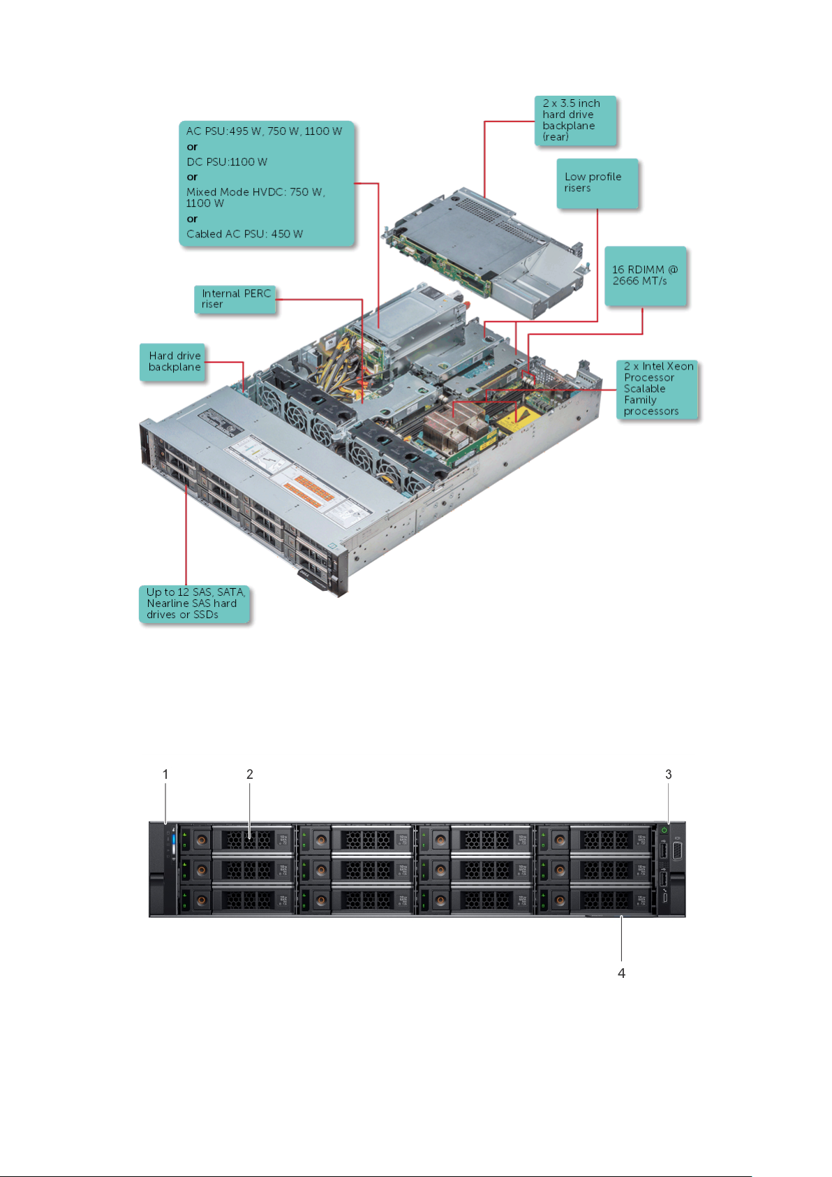
Figure 1. Supported configurations for a PowerEdge R540 system with rear drive
Front view of the system
The front view displays the features available on the front of the system.
Figure 2. Front view of 12 x 3.5-inch drive system
8
Dell EMC PowerEdge R540 overview
Page 9
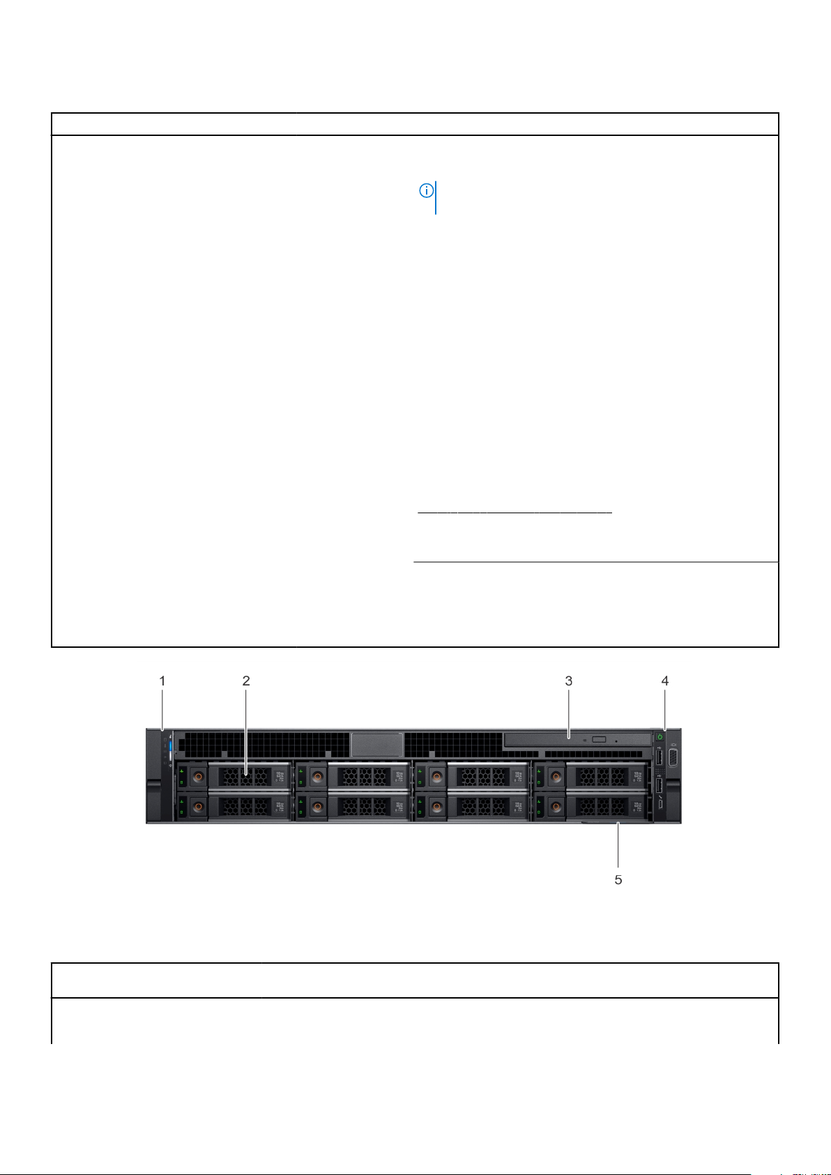
Table 1. Features available on the front of the system
Item Ports, panels, and slots Icon Description
`1 Left control panel N/A
2 Drive slots N/A Enable you to install drives that are supported on your system.
Contains the system health and system ID, status LED, and
the iDRAC Quick Sync 2 (wireless) indicator.
NOTE: The iDRAC Quick Sync 2 indicator is available only
on certain configurations.
● Status LED: Enables you to identify any failed hardware
components. There are up to five status LEDs and an
overall system health LED (Chassis health and system ID)
bar. For more information, see the Status LED indicators
section.
● Quick Sync 2 (wireless): Indicates a Quick Sync enabled
system. The Quick Sync feature is optional. This feature
enables management of the system by using mobile
devices. This feature aggregates hardware or firmware
inventory and various system level diagnostic and error
information that can be used in troubleshooting the
system. For more information, see the Integrated Dell
Remote Access Controller User’s Guide at www.dell.com/
poweredgemanuals.
For more information, see the PowerEdge R540 Technical
Specs at
www.dell.com/poweredgemanuals
3 Right control panel N/A Contains the power button, USB ports, iDRAC Direct (Micro-
AB USB), VGA port.
4 Information tag N/A
Figure 3. Front view of 8 x 3.5-inch drive system
The Information Tag is a slide-out label panel that contains
system information such as Service Tag, NIC, MAC address,
and so on. If you have opted for the secure default access to
iDRAC, the Information tag also contains the iDRAC secure
default password.
Table 2. Features available on the front of the system
Item Ports, panels, and
slots
1 Left control panel N/A
Icon Description
Contains the system health and system ID, status LED, and the
iDRAC Quick Sync 2 (wireless) indicator.
Dell EMC PowerEdge R540 overview 9
Page 10
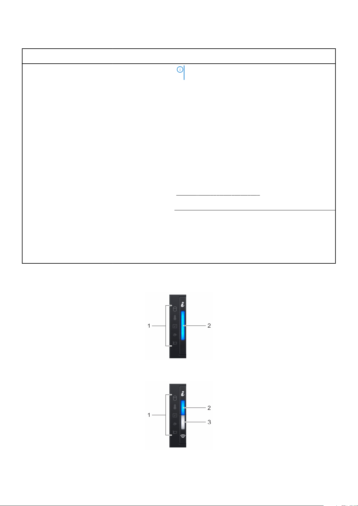
Table 2. Features available on the front of the system (continued)
Item Ports, panels, and
slots
2 Drive slots N/A Enable you to install drives that are supported on your system.
3 Optical drive (optional) N/A One optional slim SATA DVD-ROM drive or DVD+/-RW drive.
4 Right control panel N/A
5 Information tag N/A The Information Tag is a slide-out label panel that contains
Icon Description
NOTE: The iDRAC Quick Sync 2 indicator is available only
on certain configurations.
● Status LED: Enables you to identify any failed hardware
components. There are up to five status LEDs and an overall
system health LED (Chassis health and system ID) bar. For
more information, see the Status LED indicators section.
● Quick Sync 2 (wireless): Indicates a Quick Sync enabled
system. The Quick Sync feature is optional. This feature
enables management of the system by using mobile devices.
This feature aggregates hardware or firmware inventory and
various system level diagnostic and error information that
can be used in troubleshooting the system. For more
information, see the Integrated Dell Remote Access
Controller User’s Guide at www.dell.com/idracmanuals.
For more information, see the PowerEdge R540 Technical
Specs at
www.dell.com/poweredgemanuals
Contains the power button, USB ports, iDRAC Direct (Micro-AB
USB), VGA port.
system information such as Service Tag, NIC, MAC address, and
so on. If you have opted for the secure default access to iDRAC,
the Information tag also contains the iDRAC secure default
password.
Left control panel view
Figure 4. Left control panel without optional iDRAC Quick Sync 2.0 indicator
Figure 5. Left control panel with optional iDRAC Quick Sync 2.0 indicator
10
Dell EMC PowerEdge R540 overview
Page 11
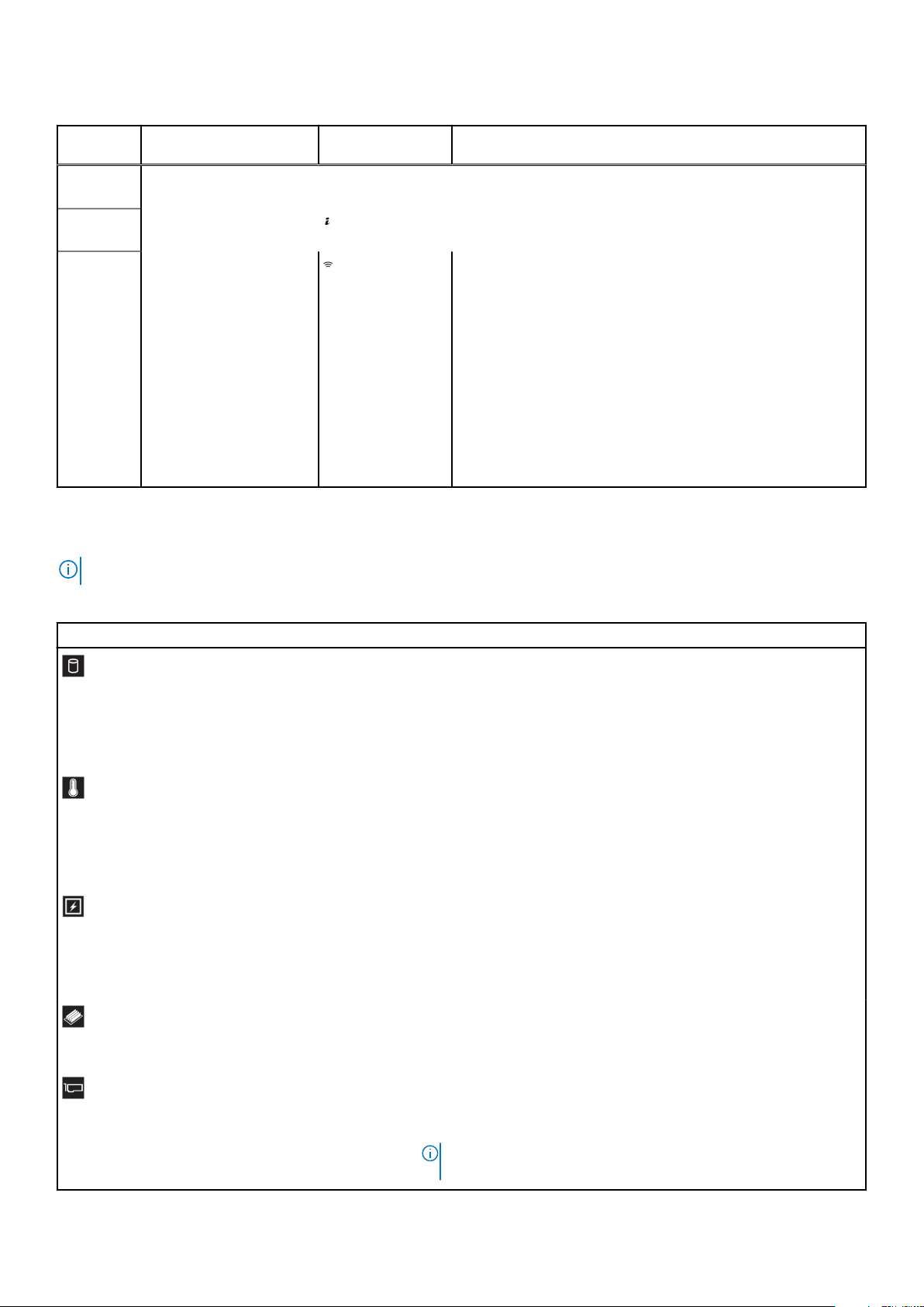
Table 3. Left control panel
Item Indicator, button, or
1 Status LED indicators N/A Indicate the status of the system. For more information, see the
2
3
connector
System health and system
ID indicator
iDRAC Quick Sync 2
wireless indicator
(optional)
Icon Description
Status LED indicators on page 11 section.
Indicates the system health.
Indicates if the iDRAC Quick Sync 2 wireless option is activated.
The Quick Sync 2 feature allows management of the system
using mobile devices. This feature aggregates hardware/
firmware inventory and various system level diagnostic/error
information that can be used in troubleshooting the system.
You can access system inventory, Dell Lifecycle Controller logs
or system logs, system health status, and also configure iDRAC,
BIOS, and networking parameters. You can also launch the
virtual Keyboard, Video, and Mouse (KVM) viewer and virtual
Kernel based Virtual Machine (KVM), on a supported mobile
device. For more information, see the Integrated Dell Remote
Access Controller User's Guide at www.dell.com/
poweredgemanuals .
Status LED indicators
NOTE: The indicators display solid amber if any error occurs.
Table 4. Status LED indicators and descriptions
Icon Description Condition Corrective action
Drive
indicator
Temperature
indicator
Electrical
indicator
Memory
indicator
The indicator turns solid amber if
there is a drive error.
The indicator turns solid amber if
the system experiences a
thermal error (for example, the
ambient temperature is out of
range or there is a fan failure).
The indicator turns solid amber if
the system experiences an
electrical error (for example,
voltage out of range, or a failed
power supply unit (PSU) or
voltage regulator).
The indicator turns solid amber if
a memory error occurs.
● Check the System Event Log to determine if the drive has an
error.
● Run the appropriate Online Diagnostics test. Restart the system
and run embedded diagnostics (ePSA).
● If the drives are configured in a RAID array, restart the system,
and enter the host adapter configuration utility program.
Ensure that none of the following conditions exist:
● A cooling fan has been removed or has failed.
● Ambient temperature is too high.
● External airflow is obstructed.
If the problem persists, see Getting help.
Check the System Event Log or system messages for the specific
issue. If it is due to a problem with the PSU, check the LED on the
PSU. Reseat the PSU.
If the problem persists, see Getting help.
Check the System Event Log or system messages for the location of
the failed memory. Reseat the memory module.
If the problem persists, see Getting help.
PCIe
indicator
The indicator turns solid amber if
a PCIe card experiences an
error.
Restart the system. Update any required drivers for the PCIe card.
Reinstall the card.
If the problem persists, see Getting help.
NOTE: For more information about the supported PCIe cards,
see Expansion card installation guidelines on page 74.
Dell EMC PowerEdge R540 overview 11
Page 12

System health and system ID indicator codes
The system health and system ID indicator is located on the left control panel of your system.
Figure 6. System health and system ID indicators
Table 5. System health and system ID indicator codes
System health and system ID indicator code Condition
Solid blue
Blinking blue Indicates that the system ID mode is active. Press the system
Solid amber Indicates that the system is in fail-safe mode. If the problem
Blinking amber Indicates that the system is experiencing a fault. Check the
Indicates that the system is turned on, system is healthy, and
system ID mode is not active. Press the system health and
system ID button to switch to system ID mode.
health and system ID button to switch to system health mode.
persists, see the Getting help section.
System Event Log or the LCD panel, if available on the bezel, for
specific error messages.
For more information about error messages, see the Event and
Error Message Reference Guide for 14th Generation Dell EMC
PowerEdge Servers at www.dell.com/qrl.
iDRAC Quick Sync 2 indicator codes
iDRAC Quick Sync 2 module (optional) is located on the front panel of your system.
Table 6. iDRAC Quick Sync 2 indicators and descriptions
iDRAC Quick Sync 2 indicator
code
Off (default state) Indicates that the iDRAC Quick Sync 2
Solid white Indicates that iDRAC Quick Sync 2 is
Blinks white rapidly Indicates data transfer activity.
Blinks white slowly Indicates that firmware update is in
Blinks white five times rapidly
and then turns off
Condition Corrective action
If the LED fails to turn on, reseat the cable and
feature is turned off. Press the iDRAC
Quick Sync 2 button to turn on the
iDRAC Quick Sync 2 feature.
ready to communicate. Press the iDRAC
Quick Sync 2 button to turn off.
progress.
Indicates that the iDRAC Quick Sync 2
feature is disabled.
check. If the problem persists, see the Getting
help section.
If the LED fails to turn off, restart the system. If
the problem persists, see the Getting help
section.
If the indicator continues to blink indefinitely, see
the Getting help section.
If the indicator continues to blink indefinitely, see
the Getting help section.
Check if iDRAC Quick Sync 2 feature is
configured to be disabled by iDRAC. If the
problem persists, see the Getting help section.
For more information, see Integrated Dell Remote
Access Controller User's Guide at www.dell.com/
poweredgemanuals or Dell OpenManage Server
Administrator User’s Guide at www.dell.com/
openmanagemanuals > OpenManage Server
Administrator.
12 Dell EMC PowerEdge R540 overview
Page 13
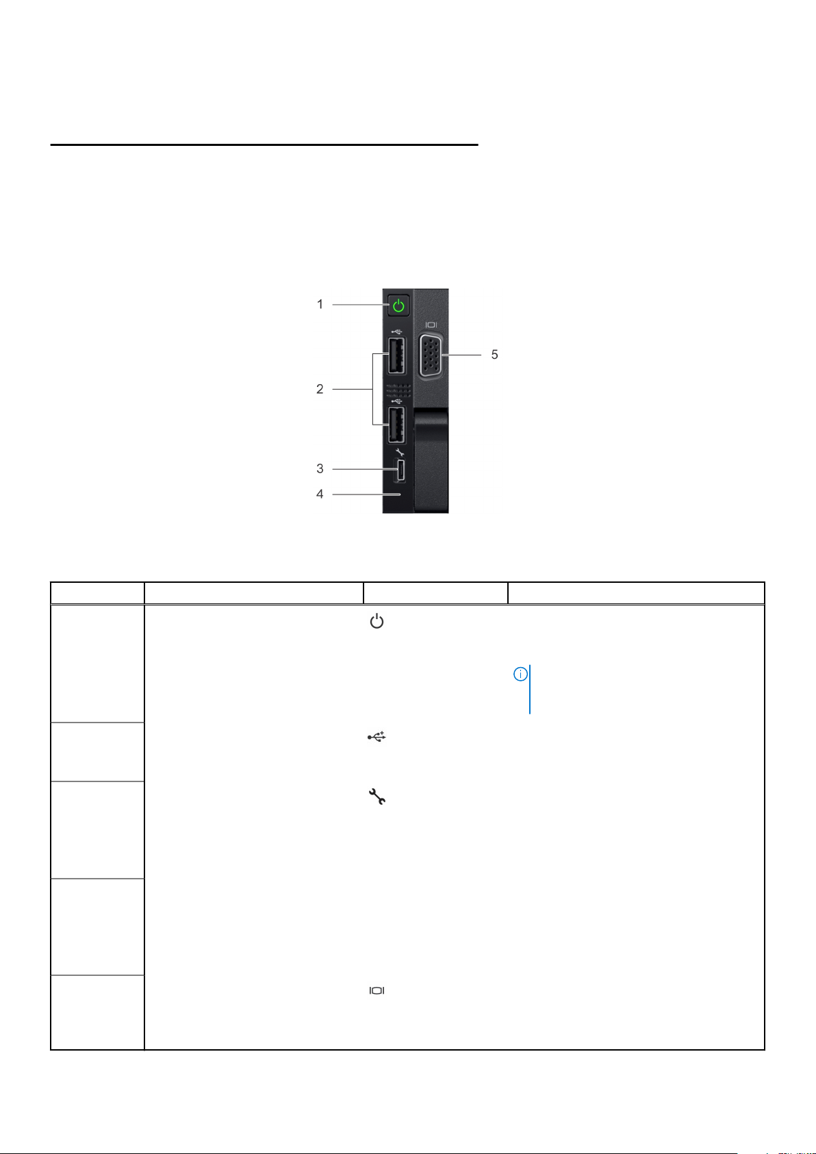
Table 6. iDRAC Quick Sync 2 indicators and descriptions (continued)
iDRAC Quick Sync 2 indicator
code
Solid amber Indicates that the system is in fail-safe
Blinking amber Indicates that the iDRAC Quick Sync 2
Condition Corrective action
Restart the system. If the problem persists, see
mode.
hardware is not responding properly.
the Getting help section.
Restart the system. If the problem persists, see
the Getting help section.
Right control panel view
Figure 7. Right control panel
Table 7. Right control panel
Item Indicator, button, or connector Icon Description
1 Power button
2
3
4
5
USB port
iDRAC Direct (Micro-AB USB) The iDRAC Direct (Micro-AB USB) port
iDRAC Direct (Micro-AB USB) LED N/A The iDRAC Direct (Micro-AB USB) LED
VGA port
Indicates if the system is powered on or off.
Press the power button to manually power
on or off the system.
NOTE: Press the power button to
gracefully shut down an ACPI-compliant
operating system.
The USB ports are 4-pin, 2.0-compliant.
These ports enable you to connect USB
devices to the system.
enables you to access the iDRAC Direct
(Micro-AB) features. For more information,
see Integrated Dell Remote Access
Controller User's Guide at www.dell.com/
poweredgemanuals.
indicator lights up to indicate that the
iDRAC Direct port is connected. For more
information, see the Integrated Dell Remote
Access Controller User's Guide at
www.dell.com/poweredgemanuals.
Enables you to connect a display device to
the system. For more information, see the
PowerEdge R540 Technical Specs at
www.dell.com/poweredgemanuals.
Dell EMC PowerEdge R540 overview 13
Page 14
iDRAC Direct LED indicator codes
The iDRAC Direct LED indicator lights up to indicate that the port is connected and is being used as a part of the iDRAC
subsystem.
You can configure iDRAC Direct by using a USB to micro USB (type AB) cable, which you can connect to your laptop or tablet.
The following table describes iDRAC Direct activity when the iDRAC Direct port is active:
Table 8. iDRAC Direct LED indicator codes
iDRAC Direct LED
indicator code
Solid green for two
seconds
Flashing green (on for
two seconds and off for
two seconds)
Turns off Indicates that the laptop or tablet is unplugged.
Condition
Indicates that the laptop or tablet is connected.
Indicates that the laptop or tablet connected is recognized.
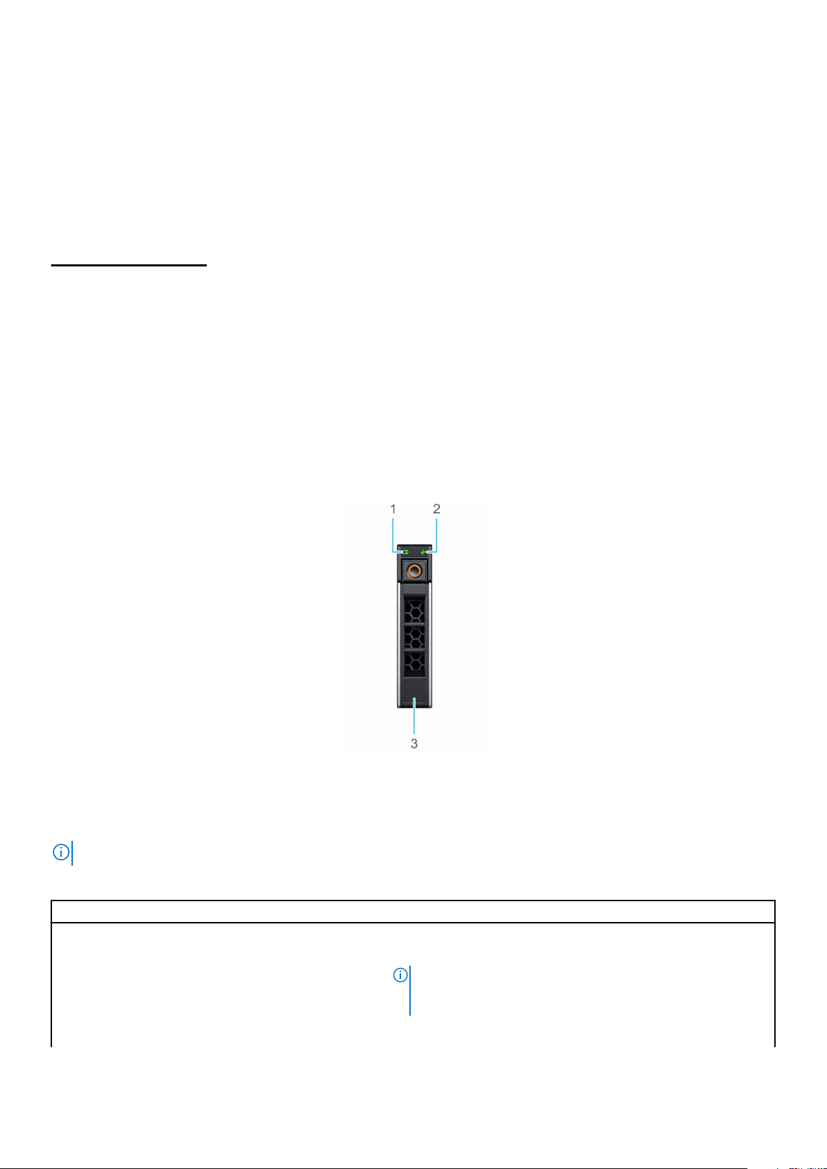
Drive indicator codes
Each drive carrier has an activity LED indicator and a status LED indicator. The indicators provide information about the current
status of the drive. The activity LED indicator indicates whether the drive is currently in use or not. The status LED indicator
indicates the power condition of the drive.
Figure 8. Drive indicators
1. Drive activity LED indicator
2. Drive status LED indicator
3. Drive capacity label
NOTE: If the drive is in the Advanced Host Controller Interface (AHCI) mode, the status LED indicator does not turn on.
Table 9. Drive indicator codes
Drive status indicator code Condition
Flashes green twice per second Identifying drive or preparing for removal.
Off Drive ready for removal.
NOTE: The drive status indicator remains off until all drives
are initialized after the system is turned on. Drives are not
ready for removal during this time.
Flashes green, amber, and then turns off Predicted drive failure.
14 Dell EMC PowerEdge R540 overview
Page 15
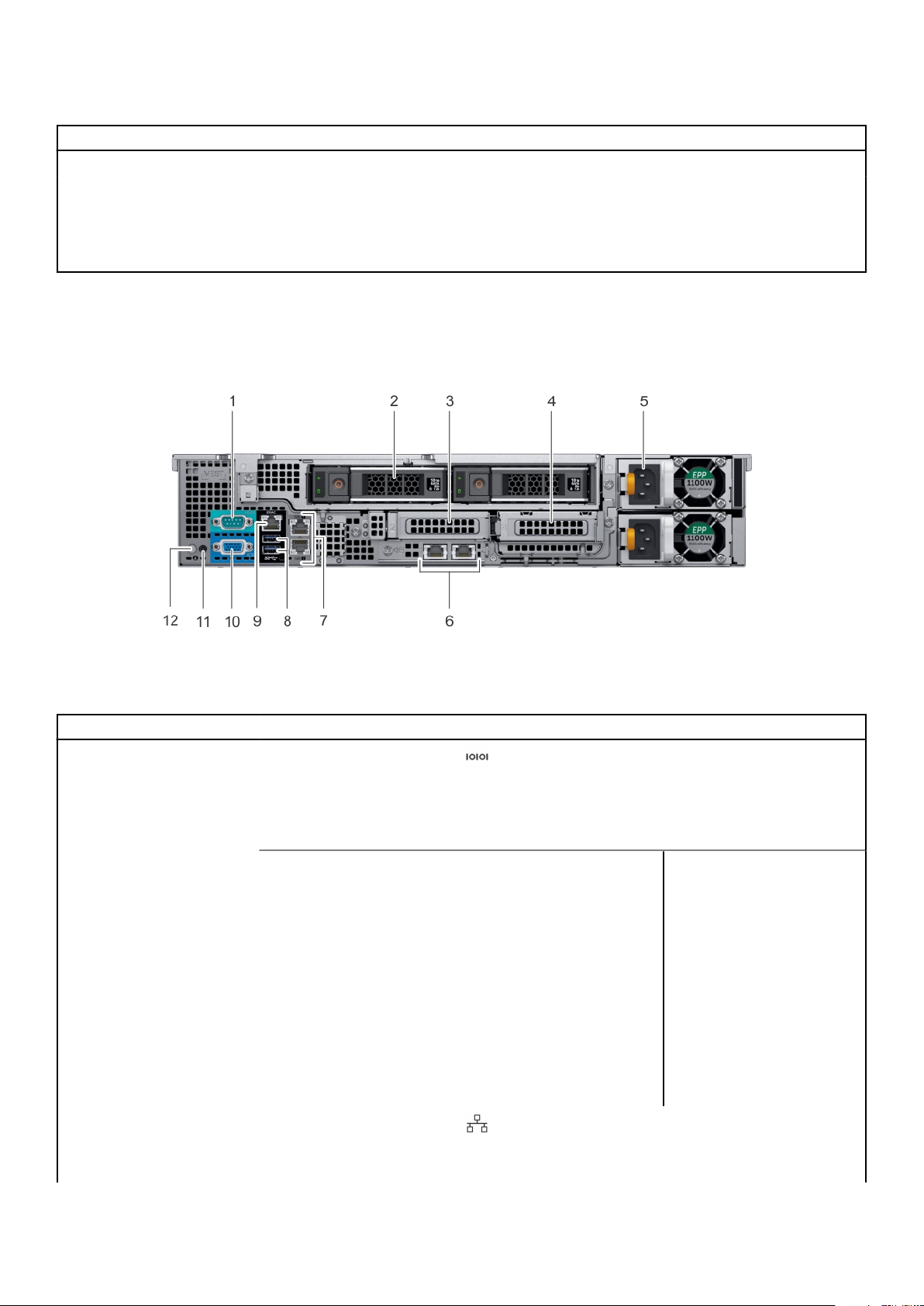
Table 9. Drive indicator codes (continued)
Drive status indicator code Condition
Flashes amber four times per second Drive failed.
Flashes green slowly Drive rebuilding.
Solid green Drive online.
Flashes green for three seconds, amber for three
seconds, and then turns off after six seconds
Rebuild stopped.
Back panel features
This back view displays the features available on the back of the system.
Figure 9. Back panel features of 12 x 3.5-inch + 2 x 3.5-inch (rear) drive system
Table 10. Back panel features of R540
Item Features Icon Description
1 Serial port Use the serial port to connect
a serial device to the system.
For more information, see the
PowerEdge R540 Technical
Specs at www.dell.com/
poweredgemanuals.
2
3 Low profile riser right slot N/A Use the card slot to connect
4 Low profile riser left slot N/A Use the card slot to connect
5 Power supply unit (PSU) (2) N/A For more information, see the
6 LOM riser port (2) Use the Ethernet or SFP+
Drive (2) N/A Two optional rear drives
supported for 12 x 3.5 -inch
system.
half-height PCIe expansion
card on low profile riser.
half-height PCIe expansion
card on low profile riser.
PowerEdge R540 Technical
Specs at www.dell.com/
poweredgemanuals.
ports to connect Local Area
Networks (LANs) to the
system. For more information
Dell EMC PowerEdge R540 overview 15
Page 16
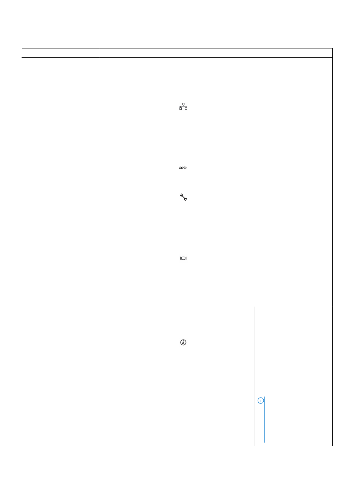
Table 10. Back panel features of R540 (continued)
Item Features Icon Description
about the supported Ethernet
or SFP+ ports. For more
information, see the
PowerEdge R540 Technical
Specs at www.dell.com/
poweredgemanuals.
7 Ethernet port (2) Use the Ethernet ports to
connect Local Area Networks
(LANs) to the system. For
more information about the
supported Ethernet ports, For
more information, see the
PowerEdge R540 Technical
Specs at www.dell.com/
poweredgemanuals.
8 USB 3.0 port (2) Use the USB 3.0 port to
connect USB devices to the
system. These ports are 4-pin,
USB 3.0-compliant.
9 iDRAC9 dedicated network
port
10 VGA port Use the VGA port to connect
11 System status indicator cable
port
12 System identification button Press the system ID button:
N/A Enables you to connect the
Use the iDRAC9 dedicated
network port to securely
access the embedded iDRAC
on a separate management
network, see the Integrated
Dell Remote Access Controller
User’s Guide at
www.dell.com/
poweredgemanuals.
a display to the system. For
more information about the
supported VGA port, For more
information, see the
PowerEdge R540 Technical
Specs at www.dell.com/
poweredgemanuals.
status indicator cable and
view system status when the
CMA is installed.
● To locate a particular
system within a rack.
● To turn the system ID on
or off.
To reset iDRAC, press and
hold the button for more than
15 s.
NOTE:
16 Dell EMC PowerEdge R540 overview
● To reset iDRAC using
system ID, ensure that
the system ID button
is enabled in the
iDRAC setup.
Page 17
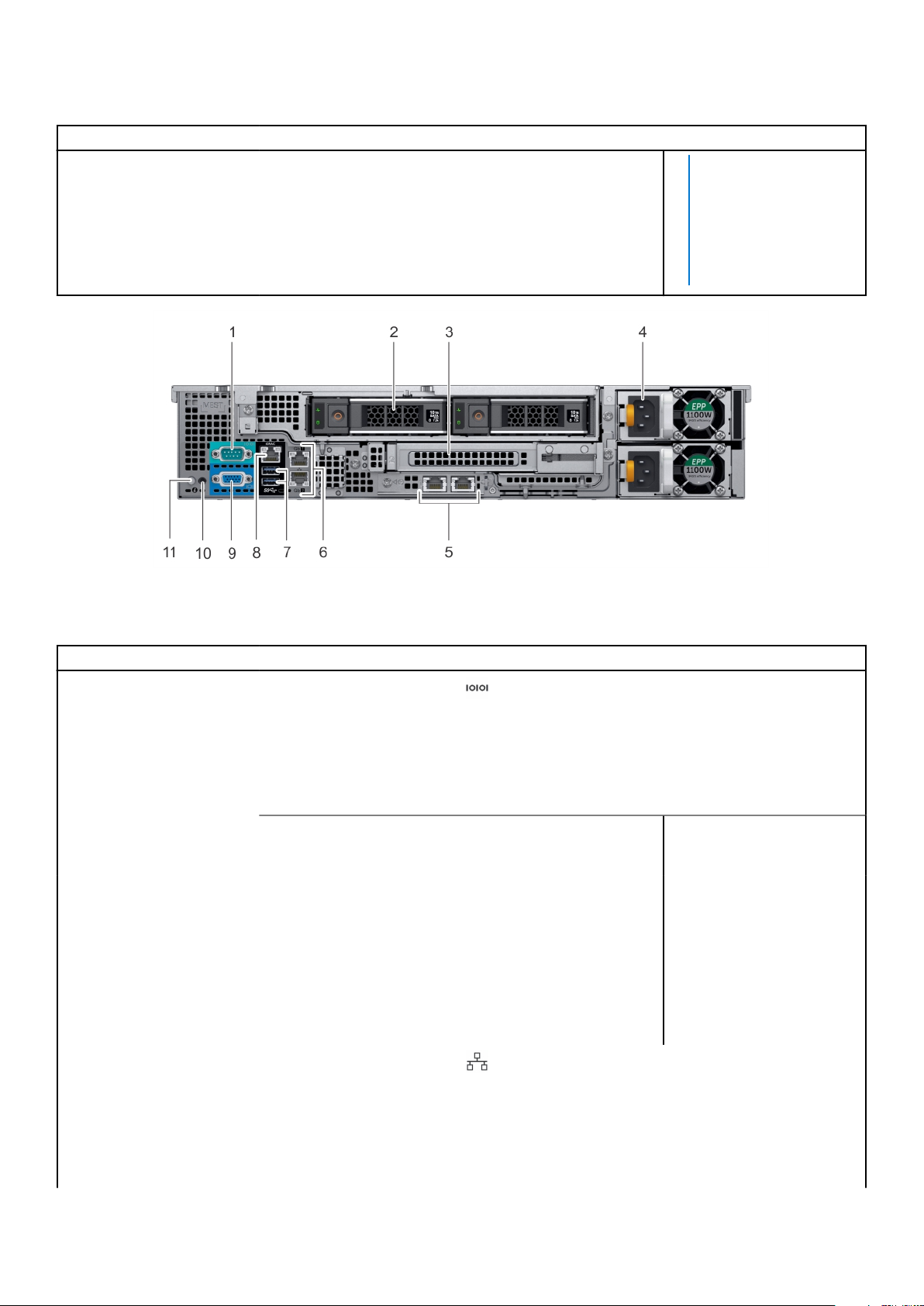
Table 10. Back panel features of R540 (continued)
Item Features Icon Description
● If the system stops
responding during
POST, press and hold
the system ID button
(for more than five
seconds) to enter the
BIOS progress mode.
Figure 10. Back panel features of 12 x 3.5-inch + 2 x 3.5-inch (rear) drive system
Table 11. Back panel features of R540
Item Features Icon Description
1 Serial port Use the serial port to connect
a serial device to the system.
For more information about
the supported serial port, For
more information, see the
PowerEdge R540 Technical
Specs at www.dell.com/
poweredgemanuals.
2
3 Full height riser slot N/A Use the card slots to connect
4 Power supply unit (PSU) (2) N/A For information about
5 LOM riser port (2) Use the Ethernet or SFP+
Drive (2) N/A Two optional rear drives
supported for 12 x 3.5 inch
system.
full-height PCIe expansion
cards on full height riser.
supported PSUs, For more
information, see the
PowerEdge R540 Technical
Specs at www.dell.com/
poweredgemanuals.
ports to connect Local Area
Networks (LANs) to the
system. For more information
about the supported Ethernet
or SFP+ ports, For more
information, see the
PowerEdge R540 Technical
Dell EMC PowerEdge R540 overview 17
Page 18
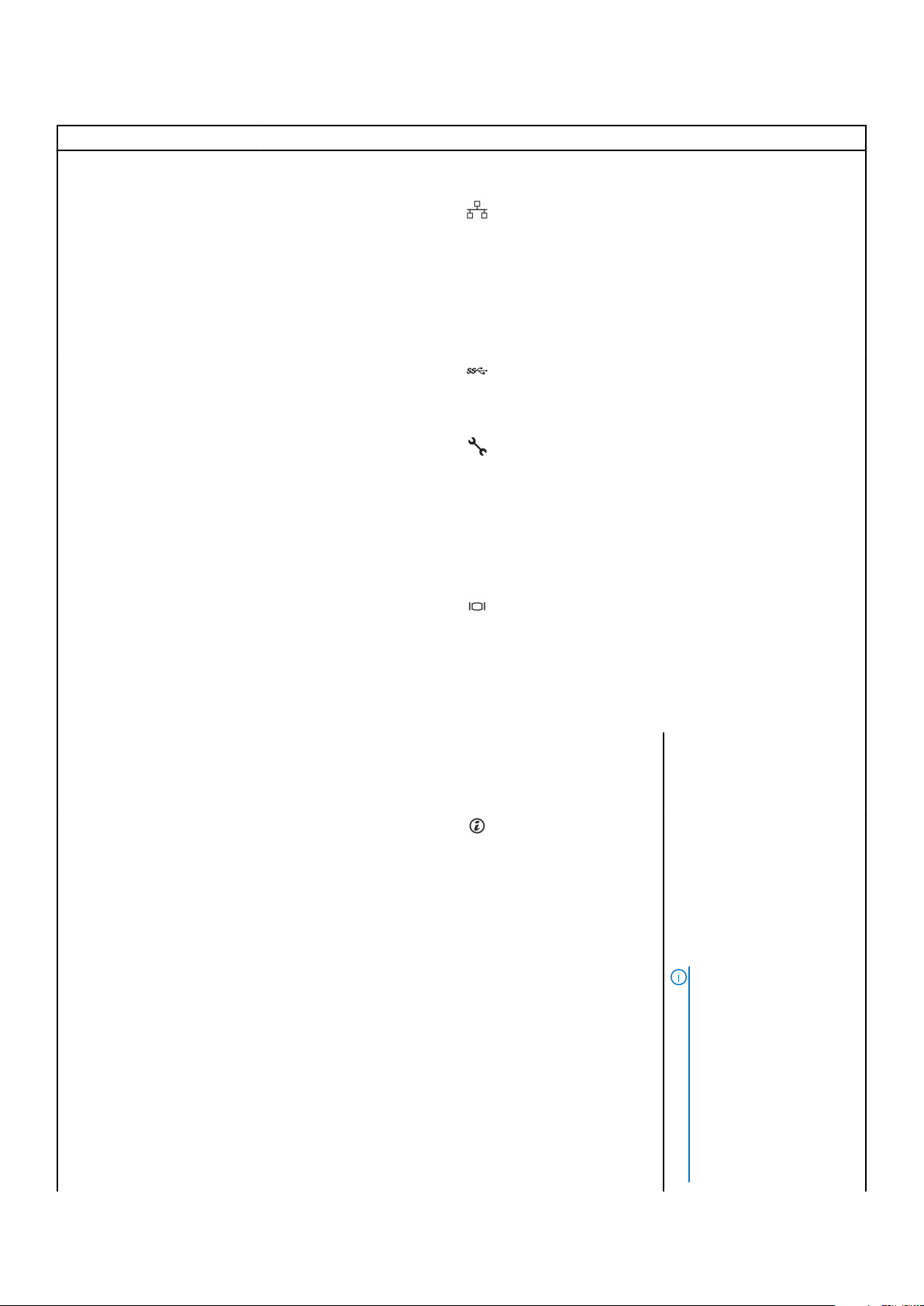
Table 11. Back panel features of R540 (continued)
Item Features Icon Description
Specs at www.dell.com/
poweredgemanuals.
6 Ethernet port (2) Use the Ethernet ports to
connect Local Area Networks
(LANs) to the system. For
more information about the
supported Ethernet ports, For
more information, see the
PowerEdge R540 Technical
Specs at www.dell.com/
poweredgemanuals.
7 USB 3.0 port (2) Use the USB 3.0 port to
connect USB devices to the
system. These ports are 4-pin,
USB 3.0-compliant.
8 iDRAC9 dedicated network
port
9 VGA port Use the VGA port to connect
10 System status indicator cable
port
11 System identification button Press the system ID button:
N/A Enables you to connect the
Use the iDRAC9 dedicated
network port to securely
access the embedded iDRAC
on a separate management
network, see the Integrated
Dell Remote Access Controller
User’s Guide at
www.dell.com/
poweredgemanuals.
a display to the system. For
more information about the
supported VGA port, For more
information, see the
PowerEdge R540 Technical
Specs at www.dell.com/
poweredgemanuals.
status indicator cable and
view system status when the
CMA is installed.
● To locate a particular
system within a rack.
● To turn the system ID on
or off.
To reset iDRAC, press and
hold the button for more than
15 seconds.
NOTE:
18 Dell EMC PowerEdge R540 overview
● To reset iDRAC using
system ID, ensure that
the system ID button
is enabled in the
iDRAC setup.
● If the system stops
responding during
POST, press and hold
the system ID button
(for more than five
Page 19
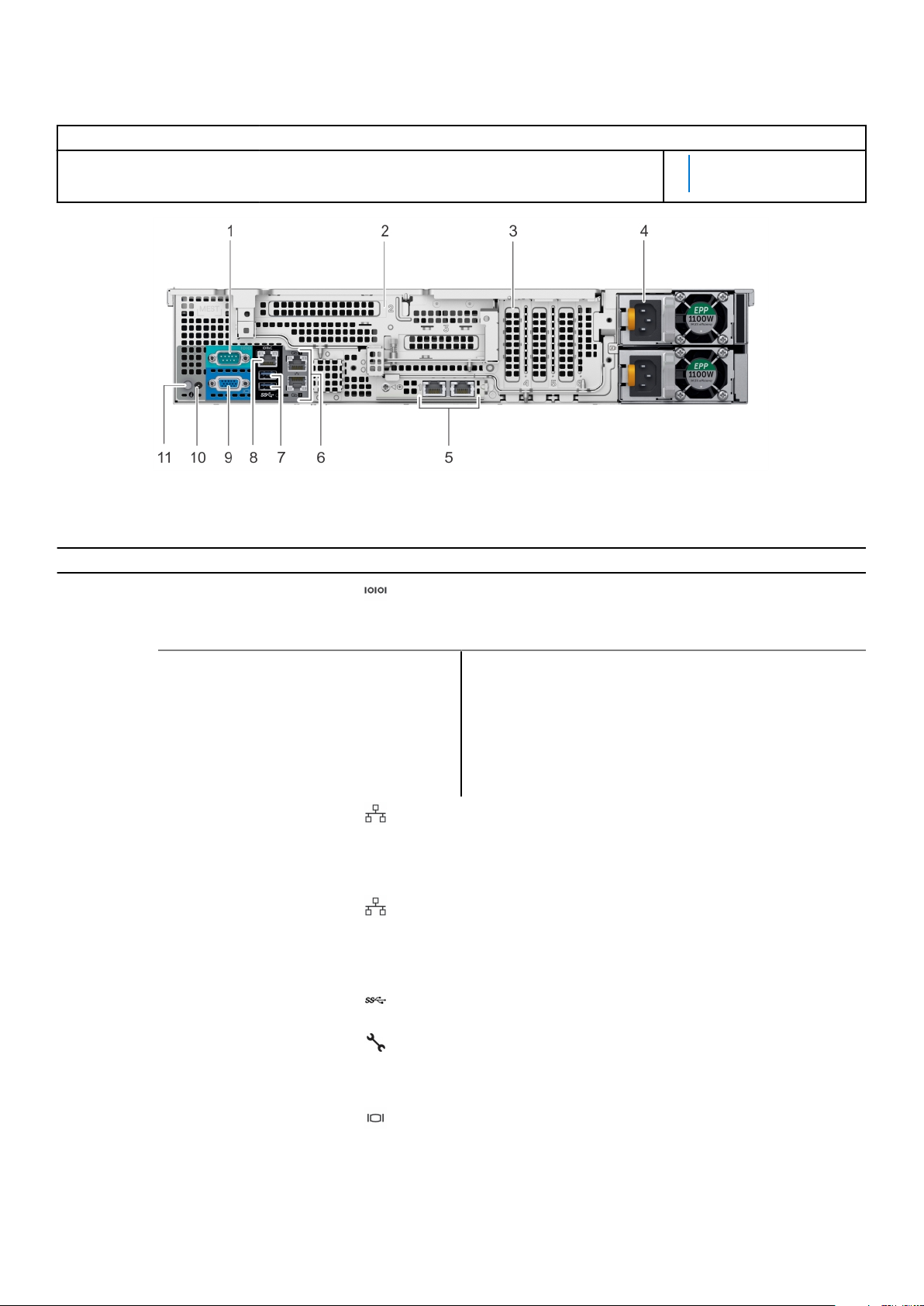
Table 11. Back panel features of R540 (continued)
Item Features Icon Description
seconds) to enter the
BIOS progress mode.
Figure 11. Back panel features of 12 x 3.5-inch drive system with butterfly riser
Table 12. Back panel features of R540
Item Features Icon Description
1 Serial port Use the serial port to connect a serial device to the system.
For more information about the supported serial port, For
more information, see the PowerEdge R540 Technical Specs
at www.dell.com/poweredgemanuals.
2
3 PCIe slot (3) N/A Use the card slots to connect up to three half-height PCIe
4 Power supply unit (PSU) N/A For information about supported PSUs, For more information,
5 LOM riser ports Use the Ethernet or SFP+ ports to connect Local Area
6 Ethernet ports (2) Use the Ethernet ports to connect Local Area Networks
7 USB 3.0 port Use the USB 3.0 port to connect USB devices to the system.
8 iDRAC9 dedicated network
9 VGA port Use the VGA port to connect a display to the system. For
Butterfly riser slot N/A Use the card slots to connect full-height PCIe expansion cards
on butterfly riser.
expansion cards on the system board.
see the PowerEdge R540 Technical Specs at www.dell.com/
poweredgemanuals.
Networks (LANs) to the system. For more information about
the supported Ethernet or SFP+ ports, For more information,
see the PowerEdge R540 Technical Specs at www.dell.com/
poweredgemanuals.
(LANs) to the system. For more information about the
supported Ethernet ports, For more information, see the
PowerEdge R540 Technical Specs at www.dell.com/
poweredgemanuals.
These ports are 4-pin, USB 3.0-compliant.
Use the iDRAC9 dedicated network port to securely access
port
the embedded iDRAC on a separate management network, see
the Integrated Dell Remote Access Controller User’s Guide at
www.dell.com/poweredgemanuals.
more information about the supported VGA port, For more
information, see the PowerEdge R540 Technical Specs at
www.dell.com/poweredgemanuals.
Dell EMC PowerEdge R540 overview 19
Page 20
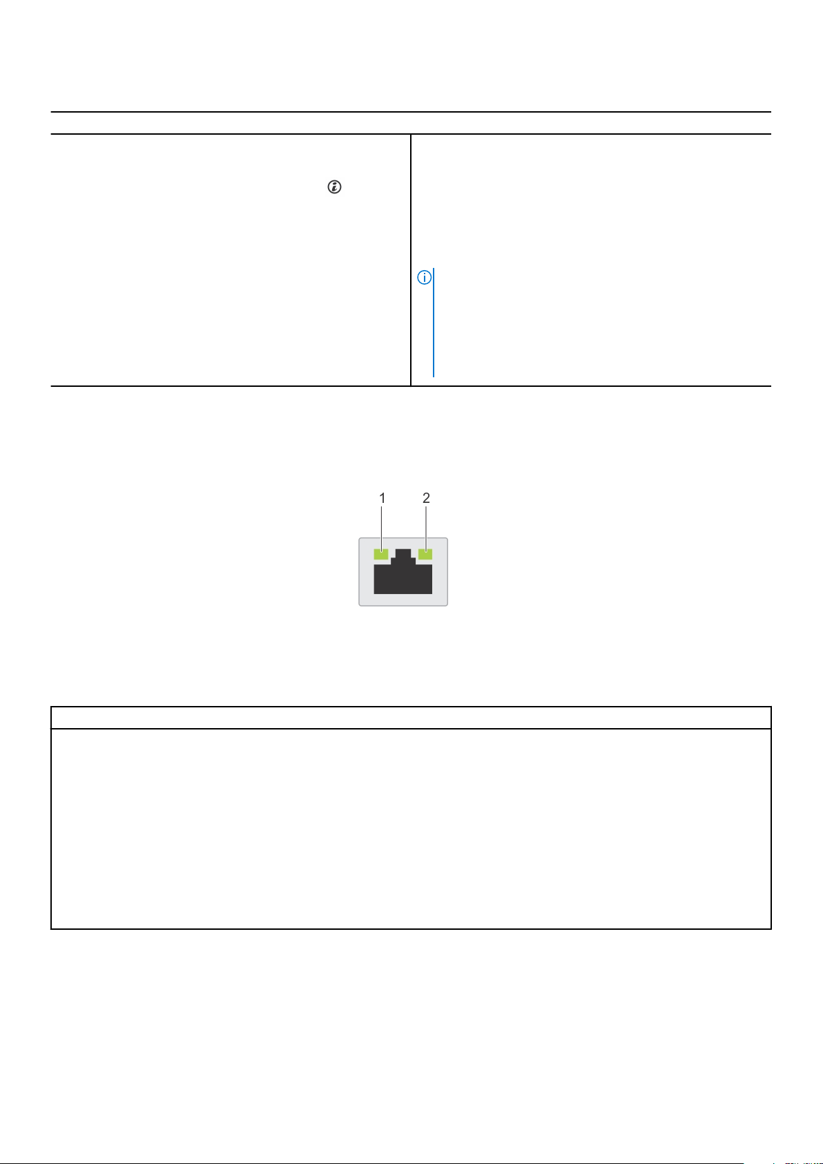
Table 12. Back panel features of R540 (continued)
Item Features Icon Description
10 Status indicator cable port N/A Enables you to connect the status indicator cable and view
system status when the CMA is installed.
11 System identification button Press the system ID button:
● To locate a particular system within a rack.
● To turn the system ID on or off.
To reset iDRAC, press and hold the button for more than 15
seconds.
NOTE:
● To reset iDRAC using system ID, ensure that the
system ID button is enabled in the iDRAC setup.
● If the system stops responding during POST, press and
hold the system ID button (for more than five seconds)
to enter the BIOS progress mode.
NIC indicator codes
Each NIC on the back of the system has indicators that provide information about the activity and link status. The activity LED
indicator indicates if data is flowing through the NIC, and the link LED indicator indicates the speed of the connected network.
Figure 12. NIC indicator codes
1. link LED indicator
2. activity LED indicator
Table 13. NIC indicator codes
Status Condition
Link and activity indicators are off The NIC is not connected to the network.
Link indicator is green and activity indicator is blinking
green
Link indicator is amber and activity indicator is blinking
green
Link indicator is green and activity indicator is off The NIC is connected to a valid network at its maximum port speed
Link indicator is amber and activity indicator is off The NIC is connected to a valid network at less than its maximum
Link indicator is blinking green and activity is off NIC identify is enabled through the NIC configuration utility.
The NIC is connected to a valid network at its maximum port speed
and data is being sent or received.
The NIC is connected to a valid network at less than its maximum
port speed and data is being sent or received.
and data is not being sent or received.
port speed and data is not being sent or received.
Power supply unit indicator codes
AC power supply units (PSUs) have an illuminated translucent handle that serves as an indicator.
The DC PSUs have an LED that serves as an indicator.
The indicator shows whether power is present or if a power fault has occurred.
20
Dell EMC PowerEdge R540 overview
Page 21
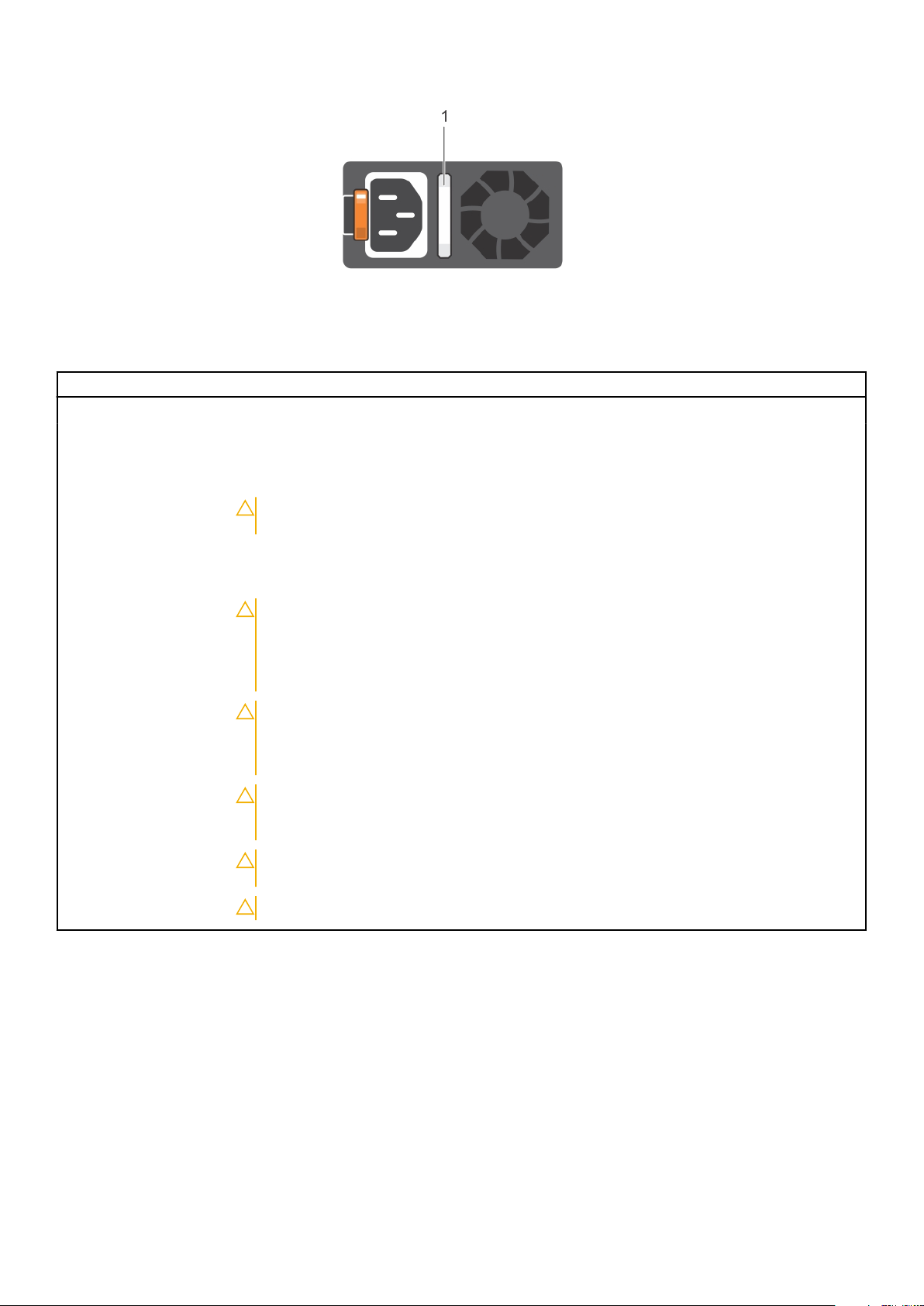
Figure 13. AC PSU status indicator
1. AC PSU status indicator/handle
Table 14. AC PSU status indicator codes
Power indicator codes Condition
Green A valid power source is connected to the PSU and the PSU is operational.
Blinking amber Indicates a problem with the PSU.
Not illuminated Power is not connected to the PSU.
Blinking green When the firmware of the PSU is being updated, the PSU handle blinks green.
CAUTION: Do not disconnect the power cord or unplug the PSU when updating
firmware. If firmware update is interrupted, the PSUs do not function.
Blinking green and turns
off
When hot-plugging a PSU, the PSU handle blinks green five times at a rate of 4 Hz and turns off.
This indicates a PSU mismatch with respect to efficiency, feature set, health status, or supported
voltage.
CAUTION: If two PSUs are installed, both the PSUs must have the same type of label;
for example, Extended Power Performance (EPP) label. Mixing PSUs from previous
generations of PowerEdge servers is not supported, even if the PSUs have the same
power rating. This results in a PSU mismatch condition or failure to turn the system
on.
CAUTION: When correcting a PSU mismatch, replace only the PSU with the blinking
indicator. Swapping the PSU to make a matched pair can result in an error condition
and unexpected system shutdown. To change from a high output configuration to a
low output configuration or vice versa, you must turn off the system.
CAUTION: AC PSUs support both 240 V and 120 V input voltages with the exception of
Titanium PSUs, which support only 240 V. When two identical PSUs receive different
input voltages, they can output different wattages, and trigger a mismatch.
CAUTION: If two PSUs are used, they must be of the same type and have the same
maximum output power.
CAUTION: Combining AC and DC PSUs is not supported and triggers a mismatch.
Dell EMC PowerEdge R540 overview 21
Page 22
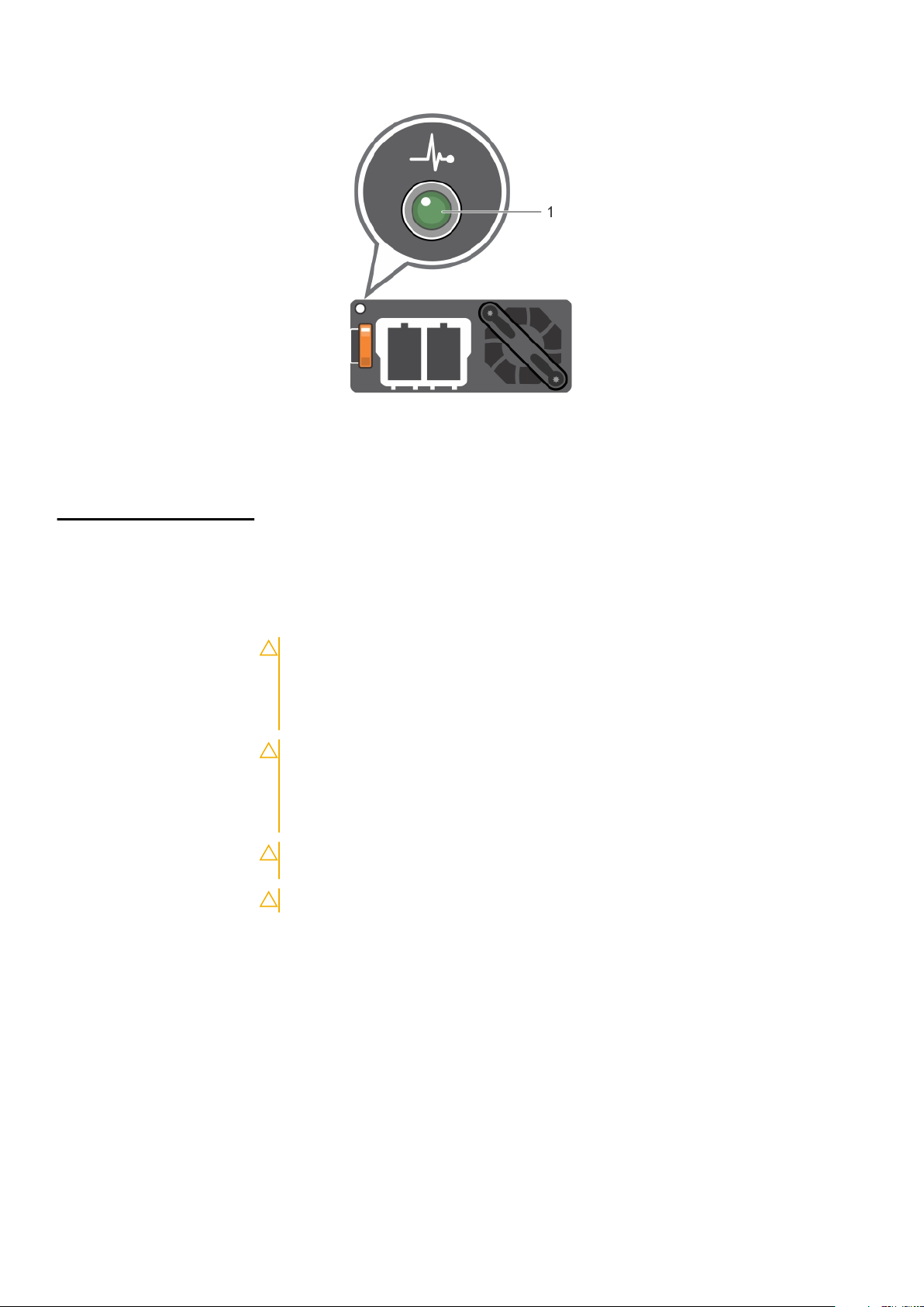
Figure 14. DC PSU status indicator
1. DC PSU status indicator
Table 15. DC PSU status indicator codes
Power indicator codes Condition
Green
Blinking amber Indicates a problem with the PSU.
Not illuminated Power is not connected to the PSU.
Blinking green When hot-plugging a PSU, the PSU indicator blinks green. This indicates that there is a PSU
A valid power source is connected to the PSU and the PSU is operational.
mismatch with respect to efficiency, feature set, health status, or supported voltage.
CAUTION: If two PSUs are installed, both the PSUs must have the same type of
label; for example, Extended Power Performance (EPP) label. Mixing PSUs from
previous generations of PowerEdge servers is not supported, even if the PSUs
have the same power rating. This results in a PSU mismatch condition or failure to
turn the system on.
CAUTION: When correcting a PSU mismatch, replace only the PSU with the
blinking indicator. Swapping the PSU to make a matched pair can result in an error
condition and unexpected system shutdown. To change from a High Output
configuration to a Low Output configuration or vice versa, you must turn off the
system.
CAUTION: If two PSUs are used, they must be of the same type and have the same
maximum output power.
CAUTION: Combining AC and DC PSUs is not supported and triggers a mismatch.
LCD panel
The LCD panel provides system information, status, and error messages to indicate if the system is functioning correctly or
requires attention. The LCD panel can also be used to configure or view the system’s iDRAC IP address. For information about
the event and error messages generated by the system firmware and agents that monitor system components, go to
qrl.dell.com > Look Up > Error Code, type the error code, and then click Look it up..
The LCD panel is available only on the optional front bezel. The optional front bezel is hot pluggable.
The statuses and conditions of the LCD panel are outlined here:
● The LCD backlight is white during normal operating conditions.
● When the system needs attention, the LCD backlight turns amber, and displays an error code followed by descriptive text.
22
Dell EMC PowerEdge R540 overview
Page 23
NOTE: If the system is connected to a power source and an error is detected, the LCD turns amber regardless of
whether the system is turned on or off.
● When the system turns off and there are no errors, LCD enters the standby mode after five minutes of inactivity. Press any
button on the LCD to turn it on.
● If the LCD panel stops responding, remove the bezel and reinstall it.
If the problem persists, see Getting help.
● The LCD backlight remains off if LCD messaging is turned off using the iDRAC utility, the LCD panel, or other tools.
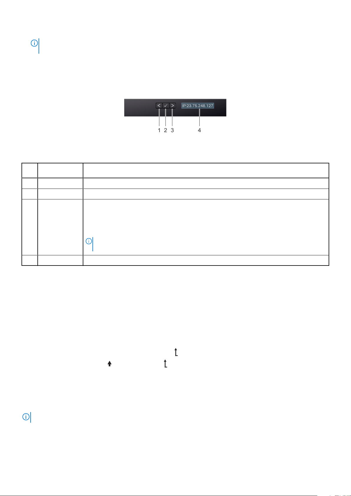
Figure 15. LCD panel features
Table 16. LCD panel features
Item Button or
display
1 Left Moves the cursor back in one-step increments.
2 Select Selects the menu item highlighted by the cursor.
3 Right Moves the cursor forward in one-step increments.
4 LCD display Displays system information, status, and error messages or iDRAC IP address.
Description
During message scrolling:
● Press and hold the right button to increase scrolling speed.
● Release the button to stop.
NOTE: The display stops scrolling when the button is released. After 45 seconds of inactivity,
the display starts scrolling.
Viewing Home screen
The Home screen displays user-configurable information about the system. This screen is displayed during normal system
operation when there are no status messages or errors. When the system turns off and there are no errors, LCD enters the
standby mode after five minutes of inactivity. Press any button on the LCD to turn it on.
Steps
1. To view the Home screen, press one of the three navigation buttons (Select, Left, or Right).
2. To navigate to the Home screen from another menu, complete the following steps:
a. Press and hold the navigation button until the up arrow is displayed.
b. Navigate to the Home icon using the up arrow .
c. Select the Home icon.
d. On the Home screen, press the Select button to enter the main menu.
Setup menu
NOTE: When you select an option in the Setup menu, you must confirm the option before proceeding to the next action.
Dell EMC PowerEdge R540 overview 23
Page 24
Option Description
iDRAC Select DHCP or Static IP to configure the network mode. If Static IP is selected, the available fields are
IP, Subnet (Sub), and Gateway (Gtw). Select Setup DNS to enable DNS and to view domain
addresses. Two separate DNS entries are available.
Set error Select SEL to view LCD error messages in a format that matches the IPMI description in the SEL. This
enables you to match an LCD message with an SEL entry.
Select Simple to view LCD error messages in a simplified user-friendly description. For information about
the event and error messages generated by the system firmware and agents that monitor system
components, go to qrl.dell.com > Look Up > Error Code, type the error code, and then click Look it up.
Set home Select the default information to be displayed on the Home screen. See View menu section for the
options and option items that can be set as the default on the Home screen.
View menu
NOTE: When you select an option in the View menu, you must confirm the option before proceeding to the next action.
Option Description
iDRAC IP Displays the IPv4 or IPv6 addresses for iDRAC9. Addresses include DNS (Primary and Secondary),
Gateway, IP, and Subnet (IPv6 does not have Subnet).
MAC Displays the MAC addresses for iDRAC, iSCSI, or Network devices.
Name Displays the name of the Host, Model, or User String for the system.
Number Displays the Asset tag or the Service tag for the system.
Power Displays the power output of the system in BTU/hr or Watts. The display format can be configured in the
Set home submenu of the Setup menu.
Temperature Displays the temperature of the system in Celsius or Fahrenheit. The display format can be configured in
the Set home submenu of the Setup menu.
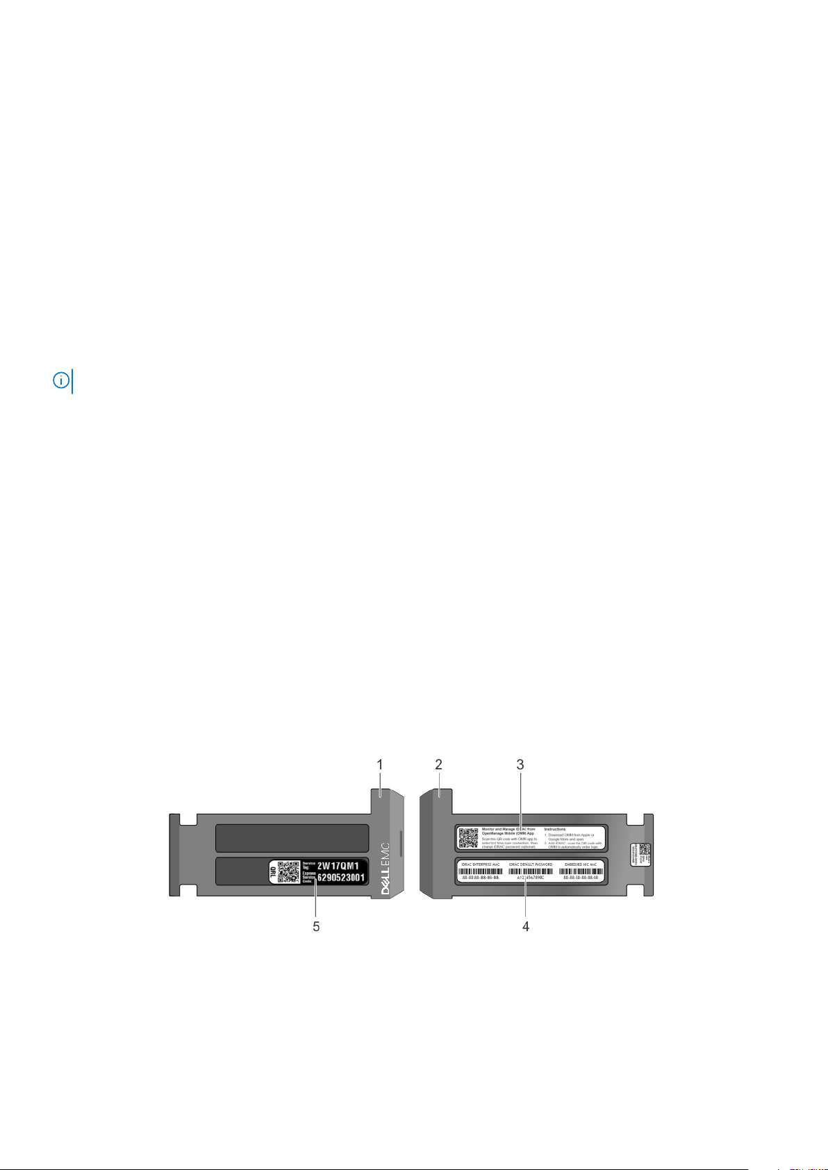
Locating the Service Tag of your system
You can identify your system using the unique Express Service Code and Service Tag. Pull out the information tag in front of the
system to view the Express Service Code and Service Tag. Alternatively, the information may be on a sticker on the chassis of
the system. The mini Enterprise Service Tag (EST) is found on the back of the system. Dell uses this information to route
support calls to the appropriate personnel.
Figure 16. Locating Service Tag of your system
1.
information tag (front view) 2. information tag (back view)
3. OpenManage Mobile (OMM) label 4. iDRAC MAC address and iDRAC secure password label
5. Service Tag
24 Dell EMC PowerEdge R540 overview
Page 25
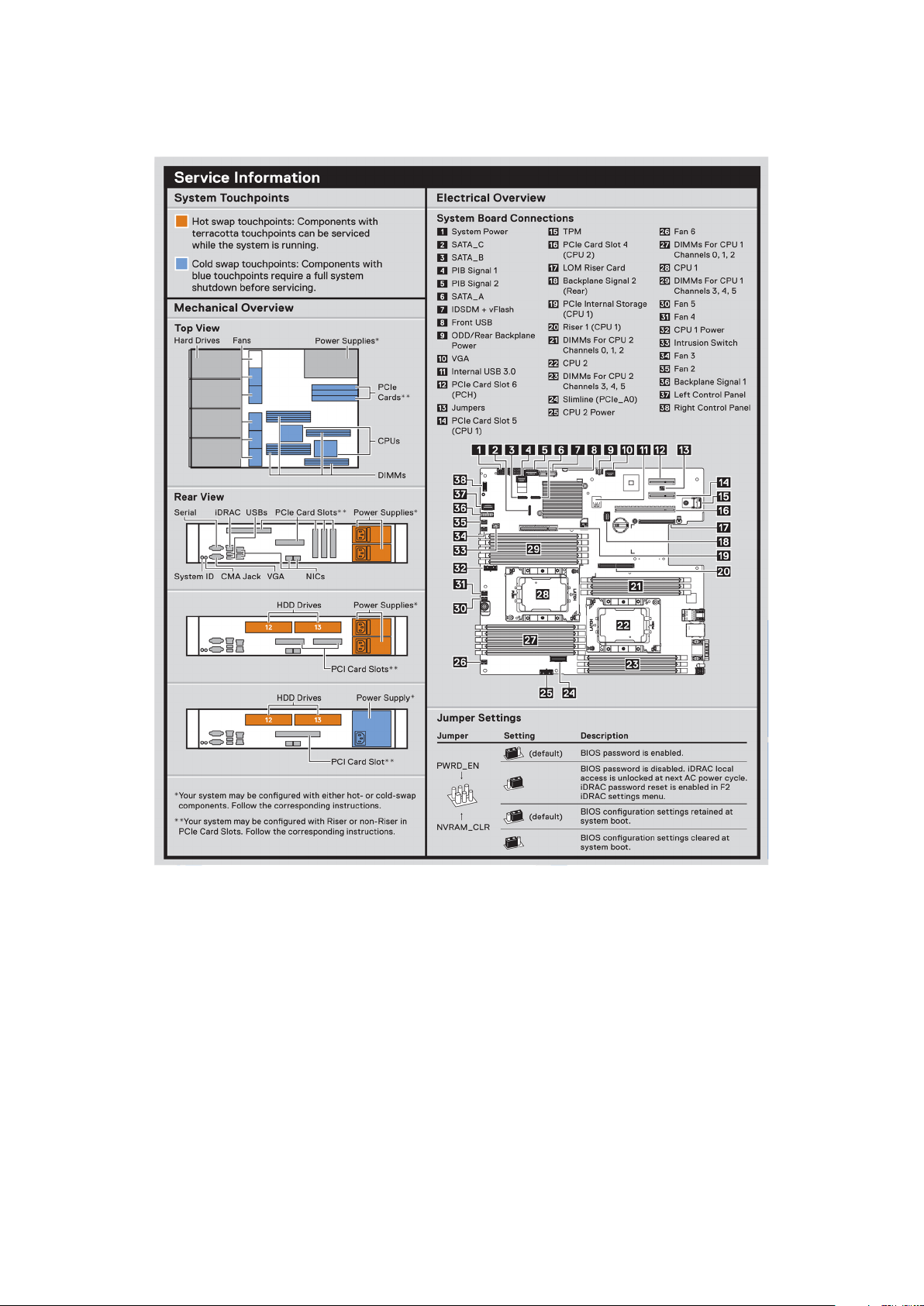
System information label
Figure 17. PowerEdge R540 – Service information
Dell EMC PowerEdge R540 overview
25
Page 26
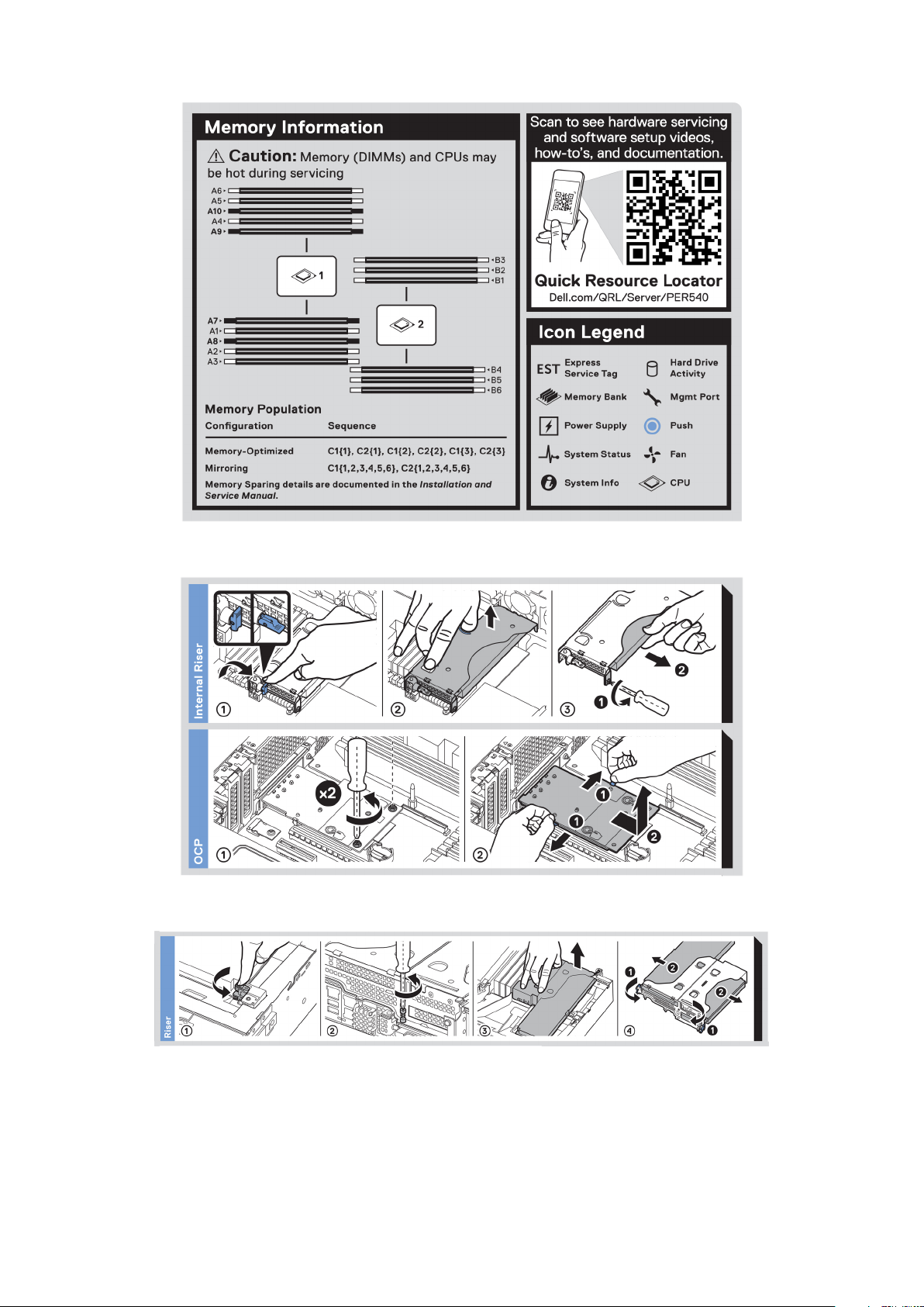
Figure 18. Memory information
Figure 19. OCP and internal PERC riser installation
Figure 20. Riser installation
26
Dell EMC PowerEdge R540 overview
Page 27
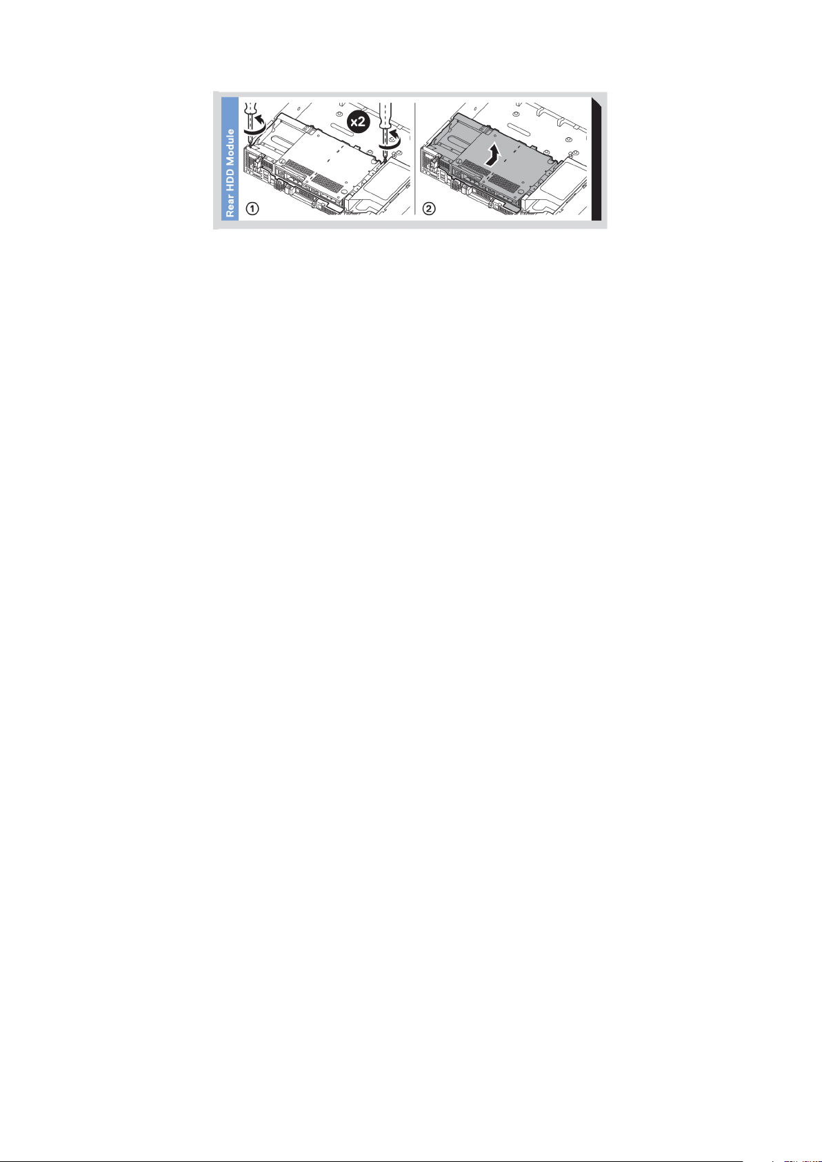
Figure 21. Rear drive installation
Dell EMC PowerEdge R540 overview 27
Page 28

2
Initial system setup and configuration
Topics:
• Setting up your system
iDRAC configuration
•
• Options to install the operating system
Setting up your system
Perform the following steps to set up your system:
Steps
1. Unpack the system.
2. Install the system into the rack. For more information about installing the system into the rack, see the Rail Installation Guide
at www.dell.com/poweredgemanuals.
3. Connect the peripherals to the system.
4. Connect the system to its electrical outlet.
5. Power on the system by pressing the power button or by using iDRAC.
6. Power on the attached peripherals.
For more information about setting up your system, see the Getting Started Guide that shipped with your system.
iDRAC configuration
The Integrated Dell Remote Access Controller (iDRAC) is designed to make system administrators more productive and improve
the overall availability of Dell systems. iDRAC alerts administrators about system issues and enables them to perform remote
system management. This reduces the need for physical access to the system.
Options to set up iDRAC IP address
To enable communication between your system and iDRAC, you must first configure the network settings based on your
network infrastructure.
NOTE: For static IP configuration, you must request for it at the time of purchase.
This option is set to DHCP by Default. You can set up the IP address by using one of the following interfaces:
Interfaces
iDRAC Settings
utility
Dell Deployment
Toolkit
Dell Lifecycle
Controller
Server LCD panel LCD panel section
iDRAC Direct and
Quick Sync 2
(optional)
Document/Section
Dell Integrated Dell Remote Access Controller User's Guide at www.dell.com/poweredgemanuals
Dell Deployment Toolkit User’s Guide at www.dell.com/openmanagemanuals > OpenManage Deployment
Toolkit
Dell Lifecycle Controller User’s Guide at www.dell.com/poweredgemanuals
See Dell Integrated Dell Remote Access Controller User's Guide at www.dell.com/poweredgemanuals
28 Initial system setup and configuration
Page 29
NOTE: To access iDRAC, ensure that you connect the ethernet cable to the iDRAC9 dedicated network port. You can also
access iDRAC through the shared LOM mode, if you have opted for a system that has the shared LOM mode enabled.
Log in to iDRAC
You can log in to iDRAC as:
● iDRAC user
● Microsoft Active Directory user
● Lightweight Directory Access Protocol (LDAP) user
If you have opted for secure default access to iDRAC, you must use the iDRAC secure default password available on the system
Information tag. If you have not opted for secure default access to iDRAC, then use the default user name and password –root
and ca lvi n. You can also log in by using your Single Sign-On or Smart Card.
NOTE: You must have the iDRAC credentials to log in to iDRAC.
NOTE: Ensure that you change the default username and password after setting up the iDRAC IP address.
For more information about logging in to the iDRAC and iDRAC licenses, see the latest Integrated Dell Remote Access Controller
User's Guide at www.dell.com/poweredgemanuals.
You can also access iDRAC by using RACADM. For more information, see the RACADM Command Line Interface Reference
Guide at www.dell.com/poweredgemanuals.
Options to install the operating system
If the system is shipped without an operating system, install a supported operating system by using one of the following
resources:
Table 17. Resources to install the operating system
Resources Location
iDRAC www.dell.com/idracmanuals
Lifecycle Controller www.dell.com/idracmanuals > Lifecycle Controller
OpenManage Deployment Toolkit www.dell.com/openmanagemanuals > OpenManage
Deployment Toolkit
Dell certified VMware ESXi www.dell.com/virtualizationsolutions
Installation and How-to videos for supported operating
systems on PowerEdge systems
Methods to download firmware and drivers
You can download the firmware and drivers by using any of the following methods:
Table 18. Firmware and drivers
Methods Location
Supported Operating Systems for Dell EMC PowerEdge
systems
From the Dell EMC support site www.dell.com/support/home
Using Dell Remote Access Controller Lifecycle Controller
(iDRAC with LC)
Using Dell Repository Manager (DRM) www.dell.com/openmanagemanuals > Repository Manager
Using Dell OpenManage Essentials www.dell.com/openmanagemanuals > OpenManage Essentials
Using Dell OpenManage Enterprise www.dell.com/openmanagemanuals > OpenManage
www.dell.com/idracmanuals
Enterprise
Initial system setup and configuration 29
Page 30

Table 18. Firmware and drivers (continued)
Methods Location
Using Dell Server Update Utility (SUU) www.dell.com/openmanagemanuals > Server Update Utility
Using Dell OpenManage Deployment Toolkit (DTK) www.dell.com/openmanagemanuals > OpenManage
Deployment Toolkit
Using iDRAC virtual media www.dell.com/idracmanuals
Downloading drivers and firmware
Dell EMC recommends that you download and install the latest BIOS, drivers, and systems management firmware on your
system.
Prerequisites
Ensure that you clear the web browser cache before downloading the drivers and firmware.
Steps
1. Go to www.dell.com/support/home.
2. In the Drivers & Downloads section, type the Service Tag of your system in the Enter a Service Tag or product ID box,
and then click Submit.
NOTE:
If you do not have the Service Tag, select Detect Product to allow the system to automatically detect the
Service Tag, or click View products, and navigate to your product.
3. Click Drivers & Downloads.
The drivers that are applicable to your system are displayed.
4. Download the drivers to a USB drive, CD, or DVD.
30
Initial system setup and configuration
Page 31

Installing and removing system components
Topics:
• Safety instructions
Before working inside your system
•
• After working inside your system
• Recommended tools
• Optional front bezel
• System cover
• Backplane cover
• Inside the system
• Air shroud
• Cooling fans
• Internal PERC riser
• Intrusion switch
• Drives
• System memory
• Processors and heat sinks
• Expansion cards and expansion card risers
• M.2 SSD module
• Optional MicroSD or vFlash card
• Optional IDSDM or vFlash module
• LOM riser card
• Drive backplane
• Cable routing
• Rear drive cage
• System battery
• Optional internal USB memory key
• Optical drive (optional)
• Power supply units
• Power interposer board
• Control panel
• System board
• Restoring the system using Easy Restore
• Entering the system Service Tag by using System Setup
• Trusted Platform Module
3
Safety instructions
Whenever you need to lift the system, get others to assist you. To avoid injury, do not attempt to lift the system by
NOTE:
yourself.
WARNING: Opening or removing the system cover while the system is powered on may expose you to a risk of
electric shock.
CAUTION: Do not operate the system without the cover for a duration exceeding five minutes. Operating the
system without the system cover can result in component damage.
CAUTION: Many repairs may only be done by a certified service technician. You should only perform
troubleshooting and simple repairs as authorized in your product documentation, or as directed by the online or
Installing and removing system components 31
Page 32

telephone service and support team. Damage due to servicing that is not authorized by Dell is not covered by
your warranty. Read and follow the safety instructions that are shipped with your product.
NOTE: It is recommended that you always use an antistatic mat and antistatic strap while working on components inside
the system.
CAUTION: To ensure proper operation and cooling, all bays in the system and system fans must be always
populated with a component or a blank.
Before working inside your system
Prerequisites
Follow the safety guidelines listed in Safety instructions on page 31.
Steps
1. Turn off the system, including all attached peripherals.
2. Disconnect the system from the electrical outlet and disconnect the peripherals.
After working inside your system
Prerequisites
Follow the safety guidelines listed in Safety instructions on page 31.
Steps
1. Reconnect the peripherals and connect the system to the electrical outlet.
2. Turn on the attached peripherals and then turn on the system.
Recommended tools
You need the following tools to perform the removal and installation procedures:
● Key to the bezel lock
The key is required only if your system includes a bezel.
● Phillips #1 screwdriver
● Phillips #2 screwdriver
● Torx #T30 screwdriver
● Torx #T8 screwdriver
● Wrist grounding strap
You need the following tools to assemble the cables for a DC power supply unit:
● AMP 90871-1 hand-crimping tool or equivalent
● Tyco Electronics 58433-3 or equivalent
● Wire-stripper pliers to remove insulation from size 10 AWG solid or stranded, insulated copper wire
NOTE: Use alpha wire part number 3080 or equivalent (65/30 stranding).
Optional front bezel
NOTE: The procedure to remove the front bezel with and without the LCD panel is the same.
32 Installing and removing system components
Page 33

Removing the front bezel
Prerequisites
Follow the safety guidelines listed in Safety instructions on page 31.
Steps
1. Unlock the bezel by using the bezel key.
2. Press the release button, and pull the left end of the bezel.
3. Unhook the right end, and remove the bezel.
Figure 22. Removing the front bezel with the LCD panel
Installing the front bezel
Prerequisites
Follow the safety guidelines listed in Safety instructions on page 31.
Steps
1. Locate and remove the bezel key.
NOTE: The bezel key is part of the LCD bezel package.
2. Align and insert the right end of the bezel onto the system.
3. Press the bezel until the button clicks in place and fit the left end of the bezel onto the system.
4. Lock the bezel by using the key.
Installing and removing system components
33
Page 34

Figure 23. Installing the front bezel with the LCD panel
System cover
NOTE:
The system cover of 12 x 3.5-inch + 2 x 3.5-inch (rear) system is different from other systems. The cover has one
additional mylar and foam layer on the front side of the system cover.
Removing the system cover
Prerequisites
1. Follow the safety guidelines listed in Safety instructions on page 31.
2. Turn off the system, including any attached peripherals.
3. Disconnect the system from the electrical outlet and disconnect the peripherals.
Steps
1. Using a 1/4 inch flat head or a Phillips #2 screwdriver, rotate the latch release lock counter clockwise to the unlocked
position.
2. Lift the latch till the system cover slides back and the tabs on the system cover disengage from the guide slots on the
system.
3. Hold the cover on both sides, and lift the cover away from the system.
34
Installing and removing system components
Page 35

Figure 24. Removing the system cover
Installing the system cover
Prerequisites
1. Follow the safety guidelines listed in Safety instructions on page 31.
2. Ensure that all internal cables are routed correctly and connected, and no tools or extra parts are left inside the system.
Steps
1. Align the tabs on the system cover with the guide slots on the system.
2. Push the system cover latch down.
The system cover slides forward, the tabs on the system cover engage with the guide slots on the system and the system
cover latch locks into place.
3. Using a 1/4 inch flat head or Phillips #2 screwdriver, rotate the latch release lock clockwise to the locked position.
Installing and removing system components
35
Page 36

Figure 25. Installing system cover
Next steps
1. Reconnect the peripherals and connect the system to the electrical outlet.
2. Turn on the system, including any attached peripherals.
Backplane cover
Removing the backplane cover
Prerequisites
1. Follow the safety guidelines listed in Safety instructions on page 31.
2. Follow the procedure listed in Before working inside your system on page 32.
3. Removing the system cover on page 34.
Steps
1. Slide the backplane cover in the direction of the arrows marked on the backplane cover.
2. Lift the backplane cover away from the system.
36
Installing and removing system components
Page 37

Figure 26. Removing backplane cover
Installing the backplane cover
Prerequisites
1. Follow the safety guidelines listed in Safety instructions on page 31.
2. Follow the procedure listed in Before working inside your system on page 32.
3. Installing the system cover on page 35.
Steps
1. Align the tabs on the backplane cover with the guide slots on the system.
2. Slide the backplane cover toward the front of the system until the cover locks into place.
Installing and removing system components
37
Page 38

Figure 27. Installing backplane cover
Next steps
Follow the procedure listed in After working inside your system on page 32.
Inside the system
NOTE: Components that are hot swappable are marked orange and touch points on the components are marked blue.
38 Installing and removing system components
Page 39

Figure 28. Inside the system without rear drive cage
Installing and removing system components
39
Page 40

Figure 29. Inside the system with rear drive cage
Information tag 2. Drive backplane
1.
3. Cooling fans 4. Memory module
5. CPU 1 6. CPU 2
7. System board 8. LOM riser card
9. Internal PERC riser 10. Air shroud
11. Butterfly riser 12. Air shroud (12 x 3.5 inch + 2 x 3.5 inch rear hard drive
system)
13. Low profile riser right 14. Low profile riser left
15. Drive cage (rear)
40 Installing and removing system components
Page 41

Air shroud
Removing the air shroud
Prerequisites
CAUTION: Never operate your system with the air shroud removed. The system may get overheated quickly,
resulting in shutdown of the system and loss of data.
1. Follow the safety guidelines listed in Safety instructions on page 31.
2. Follow the procedure listed in Before working inside your system on page 32.
3. If installed, remove the butterfly riser.
Steps
Hold the air shroud at both ends and lift it away from the system.
Figure 30. Removing air shroud
The system with 2 x 3.5-inch rear drive has a different air shroud. However, the procedure to remove the air shroud
NOTE:
is identical.
Installing and removing system components 41
Page 42

Next steps
1. If applicable, Installing the air shroud on page 42
2. Follow the procedure listed in After working inside your system on page 32.
Installing the air shroud
Prerequisites
1. Follow the safety guidelines listed in Safety instructions on page 31.
2. Follow the procedure listed in Before working inside your system on page 32.
3. If applicable, route the cables inside the system along the system wall and secure the cables by using the cable latch.
Steps
1. Align the tabs on the air shroud with the slots on the system.
2. Lower the air shroud into the system until it is firmly seated.
When firmly seated, the memory socket numbers marked on the air shroud align with the respective memory sockets.
42
Installing and removing system components
Page 43

Figure 31. Installing air shroud
NOTE: The procedure to install the air shroud for 2 x 3.5-inch rear drive system is identical.
Next steps
1. If removed, install the butterfly riser.
Installing and removing system components
43
Page 44

2. Follow the procedure listed in After working inside your system on page 32.
Cooling fans
Removing the cooling fan
The procedure for removing standard and high performance fans are identical.
Prerequisites
1. Follow the safety guidelines listed in Safety instructions on page 31.
2. Follow the procedure listed in Before working inside your system on page 32.
3. Removing the air shroud on page 41
4. Removing the internal PERC riser on page 47
5. Move the cables out of the way to access the cooling fan cable connector on the system board.
Steps
1. Lift the fan out holding the blue touch point.
2. Disconnect the cooling fan cable connected to the system board connector.
NOTE: In the 12 x 3.5-inch drive system, disconnect the fan 1 cable from the power interposer board connector.
Figure 32. Disconnecting fan cable from PIB connector
3. Press the release tab and lift the cooling fan out of the cooling fan cage.
44
Installing and removing system components
Page 45

Figure 33. Removing cooling fan
Next steps
1. Installing cooling fan on page 45.
2. Installing the internal PERC riser on page 49
3. Installing the air shroud on page 42
4. Follow the procedure listed in After working inside your system on page 32.
Installing cooling fan
The procedure for installing standard and high performance fans are identical.
Prerequisites
1. Follow the safety guidelines listed in Safety instructions on page 31.
2. Follow the procedure listed in Before working inside your system on page 32.
3. Removing the air shroud on page 41
4. Removing the internal PERC riser on page 47
5. Remove the power cable.
6. Move the cables out of the way to access the cooling fan cable connector on the system board.
Steps
1. Holding the release tab blue touch point, place the cooling fan into the cooling fan cage.
2. Route the cooling fan cable and connect it to the connector on the system board.
Installing and removing system components
45
Page 46

Figure 34. Installing cooling fan
NOTE: In the 12 x 3.5-inch drive system, connect the fan 1 cable to the power interposer board connector.
46 Installing and removing system components
Page 47

Figure 35. Connecting fan cable to PIB connector
Next steps
1. Installing the internal PERC riser on page 49
2. Ensure all the cables are routed correctly.
3. Installing the air shroud on page 42
4. Follow the procedure listed in After working inside your system on page 32.
Internal PERC riser
Removing the internal PERC riser
Prerequisites
1. Follow the safety guidelines listed in Safety instructions on page 31.
2. Follow the procedure listed in Before working inside your system on page 32.
3. Removing the air shroud on page 41
Steps
1. Open the cable guiding latch for easy access.
2. Lower the plunger.
3. Press the cable connector and disconnect the PERC cable from the backplane.
4. Hold the blue touch points and lift the internal PERC riser out of the system.
Installing and removing system components
47
Page 48

Figure 36. Removing internal PERC riser
5. Turn the internal riser so that the PERC card is facing up.
6. Press the cable connector and disconnect the cable connected to the internal PERC card.
Figure 37. Disconnecting the cable from internal PERC card
Next steps
1. Installing the air shroud on page 42
2. Follow the procedure listed in After working inside your system on page 32.
3. Installing the internal PERC riser on page 49
48
Installing and removing system components
Page 49

Installing the internal PERC riser
Prerequisites
Follow the safety guidelines listed in Safety instructions on page 31.
Steps
1. Connect the cable to the internal PERC card.
Figure 38. Connecting the cable to internal PERC riser
2. Holding the blue touch points, align the slot on the internal PERC riser to the guide on the system board.
3. Insert the internal riser card’s edge connector firmly into the system board connector until the riser is fully seated.
4. Lift the plunger to lock the riser in place.
Installing and removing system components
49
Page 50

Figure 39. Installing internal PERC riser
5. Connect the cables to the backplane and then route the cables to the cable guiding latch to close the latch.
Next steps
1. Installing the air shroud on page 42
2. Follow the procedure listed in After working inside your system on page 32.
Removing the PERC card from the internal PERC riser
Prerequisites
1. Follow the safety guidelines listed in Safety instructions on page 31.
2. Follow the procedure listed in Before working inside your system on page 32.
3. Removing the air shroud on page 41
4. Removing the internal PERC riser on page 47
Steps
1. Using a Phillips #2 screwdriver, remove the screw that secures the PERC card to the internal PERC riser.
2. Pull the PERC card out of the connector on the internal PERC riser.
50
Installing and removing system components
Page 51

Figure 40. Removing the PERC card from the internal PERC riser
Next steps
1. Installing the internal PERC riser on page 49
2. Installing the air shroud on page 42
3. Follow the procedure listed in After working inside your system on page 32.
Installing PERC card into the internal PERC riser
Prerequisites
1. Follow the safety guidelines listed in Safety instructions on page 31.
Steps
1. Insert the PERC card into the internal PERC riser and push the card in.
2. Using a Phillips #2 screwdriver, replace the screw to secure the PERC card on the internal PERC riser.
Installing and removing system components
51
Page 52

Figure 41. Installing PERC card into internal PERC riser
Next steps
1. Installing the internal PERC riser on page 49
2. Installing the air shroud on page 42
3. Follow the procedure listed in After working inside your system on page 32.
Intrusion switch
Removing the intrusion switch
Prerequisites
1. Follow the safety guidelines listed in Safety instructions on page 31.
2. Follow the procedure listed in Before working inside your system on page 32.
3. Removing the air shroud on page 41
4. Removing the internal PERC riser on page 47
Steps
1. Disconnect the intrusion switch cable connected to the system board.
NOTE: Ensure that you note the routing of the cables as you remove them from the system board.
2. Slide the intrusion switch out of the intrusion switch slot.
52
Installing and removing system components
Page 53

Figure 42. Removing an intrusion switch
Next steps
Installing the intrusion switch on page 53.
Installing the intrusion switch
Prerequisites
1. Follow the safety guidelines listed in Safety instructions on page 31.
2. Follow the procedure listed in Before working inside your system on page 32.
Steps
1. Align the intrusion switch with the intrusion switch slot.
Installing and removing system components
53
Page 54

Figure 43. Installing intrusion switch
2. Slide the intrusion switch until it is firmly seated in the intrusion switch slot.
3. Connect the intrusion switch cable to the connector on the system board.
Next steps
1. Installing the internal PERC riser on page 49
2. Follow the procedure listed in After working inside your system on page 32.
Drives
The PowerEdge R540 system supports:
● Up to 14 x 3.5 inch drives or 2.5 inch drives with drive adapter, internal, hot swappable SAS, SATA, or Nearline SAS drives
● Up to 8 x 3.5 inch drives or 2.5 inch drives with drive adapter, internal, hot swappable SATA SSDs
Removing a drive blank
The procedure for removing 2.5-inch and 3.5-inch drive blanks is identical.
Prerequisites
1. Follow the safety guidelines listed in Safety instructions on page 31.
2. If installed, Removing the front bezel on page 33
CAUTION: To maintain proper system cooling, drive blanks must be installed in all empty drive slots.
CAUTION: Mixing drive blanks from previous generations of PowerEdge servers is not supported.
Steps
Press the release button, and slide the drive blank out of the drive slot.
54
Installing and removing system components
Page 55

Figure 44. Removing a drive blank
Next steps
1. Installing a drive blank on page 55
Installing a drive blank
The procedure for installing 2.5-inch and 3.5-inch drive blanks is identical.
Prerequisites
1. Follow the safety guidelines listed in Safety instructions on page 31.
2. If installed, Removing the front bezel on page 33
CAUTION: Mixing drive blanks from previous generations of PowerEdge servers is not supported.
Steps
Insert the drive blank into the drive slot, and push the blank until the release button clicks into place.
Figure 45. Installing a drive blank
Next steps
If removed, Installing the front bezel on page 33
Removing a 2.5-inch drive from a 3.5-inch drive adapter
Prerequisites
1. Follow the safety guidelines listed in Safety instructions on page 31.
2. Removing a 3.5-inch drive adapter from a 3.5-inch drive carrier on page 57
Installing and removing system components
55
Page 56

NOTE: A 2.5 inch drive is installed in a 3.5 inch drive adapter, which is then installed in the 3.5-inch drive carrier.
Steps
1. Using a Phillips #2 screwdriver, remove the screws from the side of the 3.5-inch drive adapter.
NOTE: If the hard drive or SSD carrier has Torx screw, use Torx 6 screwdriver to remove the drive.
2. Remove the 2.5-inch drive from the 3.5-inch drive adapter.
Figure 46. Removing a 2.5 inch drive from a 3.5-inch drive adapter
Next steps
Installing a 2.5-inch drive into a 3.5-inch drive adapter on page 56
Installing a 2.5-inch drive into a 3.5-inch drive adapter
Prerequisites
1. Follow the safety guidelines listed in Safety instructions on page 31.
2. Removing a 3.5-inch drive adapter from a 3.5-inch drive carrier on page 57
Steps
1. Align the screw holes on the 2.5-inch drive with the screw holes on the 3.5-inch drive adapter.
2. Using a Phillips #2 screwdriver, secure the 2.5-inch drive to the 3.5-inch drive adapter.
If the hard drive or SSD carrier has Torx screw, use Torx 6 screwdriver to remove the drive.
NOTE:
56 Installing and removing system components
Page 57

Figure 47. Installing a 2.5-inch drive into a 3.5-inch drive adapter
Removing a 3.5-inch drive adapter from a 3.5-inch drive carrier
Prerequisites
1. Follow the safety guidelines listed in Safety instructions on page 31.
2. If installed, Removing the front bezel on page 33
3. Remove the 3.5-inch drive carrier from the system.
Steps
1. Using a Phillips #1 screwdriver, remove the screws from the rails on the drive carrier.
NOTE: If the 3.5-inch drive has Torx screw, use Torx 6 screwdriver to remove the drive from a 3.5-inch drive adapter.
2. Lift the 3.5 inch drive adapter out of the 3.5-inch drive carrier.
Installing and removing system components
57
Page 58

Figure 48. Removing a 3.5-inch drive adapter from a 3.5-inch drive carrier
Next steps
Installing a 3.5-inch drive adapter into the 3.5-inch drive carrier on page 58
Installing a 3.5-inch drive adapter into the 3.5-inch drive carrier
Prerequisites
1. Follow the safety guidelines listed in Safety instructions on page 31.
2. Install the 2.5-inch drive into the 3.5-inch drive adapter.
Steps
1. Insert the 3.5-inch drive adapter into the 3.5-inch drive carrier with the connector end of the drive toward the back of the
3.5-inch drive carrier.
2. Align the screw holes on the 3.5-inch drive adapter with the holes on the 3.5-inch drive carrier.
3. Using a Phillips #1 screwdriver, secure the 3.5-inch drive adapter to the 3.5-inch carrier.
NOTE: If the 3.5-inch drive has Torx screw, use Torx 6 screwdriver to remove the drive from a 3.5-inch drive adapter.
58 Installing and removing system components
Page 59

Figure 49. Installing a 3.5-inch drive adapter into the 3.5-inch drive carrier
Next steps
1. Install the 3.5-inch drive carrier into the system.
2. If removed, install the front bezel.
Removing a drive carrier
Prerequisites
1. Follow the safety guidelines listed in Safety instructions on page 31.
2. If applicable, remove the front bezel.
3. Using the management software, prepare the drive for removal.
If the drive is online, the green activity or fault indicator flashes while the drive is turning off. When the drive indicators are
off, the drive is ready for removal. For more information, see the documentation for the storage controller.
CAUTION:
for the storage controller card to ensure that the host adapter is configured correctly to support drive
removal and insertion.
CAUTION: Mixing drives from previous generations of PowerEdge servers is not supported.
CAUTION: To prevent data loss, ensure that your operating system supports drive installation. See the
documentation supplied with your operating system.
Steps
1. Press the release button to open the drive carrier release handle.
2. Holding the handle, slide the drive carrier out of the drive slot.
Before attempting to remove or install a drive while the system is running, see the documentation
Installing and removing system components
59
Page 60

Figure 50. Removing a drive carrier
Next steps
1. Follow the procedure listed in After working inside your system on page 32.
2. Install a drive carrier.
3. If you are not replacing the drive immediately, Insert a drive blank in the empty drive slot to maintain proper system cooling.
Installing a drive carrier
Prerequisites
CAUTION:
the storage controller card to ensure that the host adapter is configured correctly to support drive removal and
insertion.
CAUTION: Mixing drives from previous generations of PowerEdge servers is not supported.
CAUTION: Combining SAS and SATA drives in the same RAID volume is not supported.
CAUTION: When installing a drive, ensure that the adjacent drives are fully installed. Inserting a drive carrier
and attempting to lock its handle next to a partially installed carrier can damage the partially installed carrier's
shield spring and make it unusable.
Before attempting to remove or install a drive while the system is running, see the documentation for
CAUTION: To prevent data loss, ensure that your operating system supports hot-swap drive installation. See the
documentation supplied with your operating system.
CAUTION: When a replacement hot swappable drive is installed and the system is powered on, the drive
automatically begins to rebuild. Ensure that the replacement drive is blank or contains data that you wish to
overwrite. Any data on the replacement drive is immediately lost after the drive is installed.
1. Follow the safety guidelines listed in Safety instructions on page 31.
2. If applicable, remove the drive blank.
Steps
1. Press the release button on the front of the drive carrier to open the release handle.
2. Insert the drive carrier into the drive slot and slide until the drive connects with the backplane.
3. Close the drive carrier release handle to lock the drive in place.
60
Installing and removing system components
Page 61

Figure 51. Installing a drive carrier
Next steps
If applicable, install the front bezel.
Removing the drive from the drive carrier
Prerequisites
CAUTION: Mixing drives from previous generations of PowerEdge servers is not supported.
Steps
1. Using a Phillips #1 screwdriver, remove the screws from the slide rails on the drive carrier.
2. Lift the drive out of the drive carrier.
Figure 52. Removing the drive from the drive carrier
Installing and removing system components
61
Page 62

Next steps
If applicable, Installing a drive into the drive carrier on page 62
Installing a drive into the drive carrier
Prerequisites
CAUTION: Mixing drive carriers from other generations of PowerEdge servers is not supported.
NOTE: When installing a drive into the drive carrier, ensure that the screws are torqued to 4 in-lbs.
Steps
1. Insert the drive into the drive carrier with the connector end of the drive towards the back of the carrier.
2. Align the screw holes on the drive with the screws holes on the drive carrier.
When aligned correctly, the back of the drive is flush with the back of the drive carrier.
3. Using a Phillips #1 screwdriver, secure the drive to the drive carrier with screws.
Figure 53. Installing a drive into the drive carrier
System memory
System memory guidelines
The PowerEdge systems support DDR4 Registered DIMMs (RDIMMs), and Load Reduced DIMMs (LRDIMMs). The processor
runs the instructions that are held by the system memory.
Your system contains 16 memory sockets. Processor 1 supports up to 10 memory sockets and Processor 2 supports up to six
memory sockets. Six memory channels are allocated to each processor. Processor 1 has four 2xDIMM slots per channel and two
1xDIMM slot per channel. Processor 2 has six 1xDIMM per channel.
62
Installing and removing system components
Page 63

Figure 54. Memory socket locations
Memory channels are organized as follows:
Table 19. Memory channels
Processor Channel 0 Channel 1 Channel 2 Channel 3 Channel 4 Channel 5
Processor 1 Slots A1 and A7 Slots A2 andA8Slots A3 Slots A4 and A9 Slots A5 and A10 Slots A6
Processor 2 Slots B1 Slots B2 Slots B3 Slots B4 Slots B5 Slots B6
General memory module installation guidelines
To ensure optimal performance of your system, observe the following general guidelines when configuring your system memory.
If your system's memory configurations fail to observe these guidelines, your system might not boot, stop responding during
memory configuration, or operate with reduced memory.
● System profile selected (for example, Performance Optimized, or Custom [can be run at high speed or lower])
● Maximum supported DIMM speed of the processors.
● Maximum supported DIMM speed of the processors.
● Maximum supported speed of the DIMMs
NOTE: MT/s indicates DIMM speed in MegaTransfers per second.
The system supports Flexible Memory Configuration, enabling the system to be configured and run in any valid chipset
architectural configuration. The following are the recommended guidelines for installing memory modules:
● All DIMMs must be DDR4.
Installing and removing system components
63
Page 64

● RDIMMs and LRDIMMs must not be mixed.
● 64 GB LRDIMMs that are DDP (Dual Die Package) LRDIMMs must not be mixed with 128 GB LRDIMMs that are TSV
(Through Silicon Via/3DS) LRDIMMs.
● x4 and x8 DRAM based memory modules can be mixed.
● Up to two RDIMMs can be populated per channel regardless of rank count.
● Up to two LRDIMMs can be populated per channel regardless of rank count.
● A maximum of two different ranked DIMMs can be populated in a channel regardless of rank count.
● If memory modules with different speeds are installed, they will operate at the speed of the slowest installed memory
module(s).
● Populate memory module sockets only if a processor is installed.
○ For single-processor systems, sockets A1 to A10 are available.
○ For dual-processor systems, sockets A1 to A10 and sockets B1 to B6 are available.
● Populate all the sockets with white release tabs first, followed by the black release tabs.
● When mixing memory modules with different capacities, populate the sockets with memory modules with the highest
capacity first.
NOTE: For example, if you want to mix 8 GB and 16 GB memory modules, populate 16 GB memory modules in the
sockets with white release tabs and 8 GB memory modules in the sockets with black release tabs.
● Memory modules of different capacities can be mixed provided other memory population rules are followed.
NOTE: For example, 8 GB and 16 GB memory modules can be mixed.
● In a dual-processor configuration, the memory configuration for each processor must be identical.
NOTE: For example, if you populate socket A1 for processor 1, then populate socket B1 for processor 2, and so on.
● Mixing of more than two memory module capacities in a system is not supported.
● Unbalanced memory configurations will result in a performance loss so always populate memory channels identically with
identical DIMMs for best performance.
● Populate six identical memory modules per processor (one DIMM per channel) at a time to maximize performance.
DIMM population update for Performance Optimized mode with quantity of 4 and 8 DIMMs per processor.
● When the DIMM quantity is 4 per processor, the population is slot 1, 2, 4, 5.
● When the DIMM quantity is 8 per processor, the population is slot 1, 2, 4, 5, 7, 8, 9, 10.
Mode-specific guidelines
The configurations allowed depend on the memory mode selected in the System BIOS.
Table 20. Memory operating modes
Memory Operating Mode Description
Optimizer Mode The Optimizer Mode if enabled, the DRAM controllers
operate independently in the 64-bit mode and provide
optimized memory performance.
Mirror Mode The Mirror Mode if enabled, the system maintains two
identical copies of data in memory, and the total available
system memory is one half of the total installed physical
memory. Half of the installed memory is used to mirror the
active memory modules. This feature provides maximum
reliability and enables the system to continue running even
during a catastrophic memory failure by switching over to the
mirrored copy. The installation guidelines to enable Mirror
Mode require that the memory modules be identical in size,
speed, and technology, and they must be populated in sets of
6 per processor.
Single Rank Spare Mode Single Rank Spare Mode allocates one rank per channel as a
spare. If excessive correctable errors occur in a rank or
channel, while the operating system is running, they are
moved to the spare area to prevent errors from causing an
64 Installing and removing system components
Page 65

Table 20. Memory operating modes (continued)
Memory Operating Mode Description
uncorrectable failure. Requires two or more ranks to be
populated in each channel.
Multi Rank Spare Mode Multi Rank Spare Mode allocates two ranks per channel as a
spare. If excessive correctable errors occur in a rank or
channel, while the operating system is running, they are
moved to the spare area to prevent errors from causing an
uncorrectable failure. Requires three or more ranks to be
populated in each channel.
With single rank memory sparing enabled, the system
memory available to the operating system is reduced by one
rank per channel.
For example, in a dual-processor configuration with sixteen 16
GB dual-rank memory modules, the available system memory:
16 GB x 16(memory modules) - 8GB(1 rank sparing/channel) x
12(channel) = 256 GB - 96 GB = 160 GB. For multi rank
sparing, in a dual-processor configuration with sixteen 64 GB
quad-rank memory modules, the available system memory:
64 GB x 16(memory modules) - 32 GB(2 rank sparing/
channel)
x 12 (channel) = 1024 GB - 384 GB = 640 GB.
NOTE: To use memory sparing, this feature must be
enabled in the BIOS menu of System Setup.
NOTE: Memory sparing does not offer protection against
a multi-bit uncorrectable error.
Dell Fault Resilient Mode The Dell Fault Resilient Mode if enabled, the BIOS creates
an area of memory that is fault resilient. This mode can be
used by an OS that supports the feature to load critical
applications or enables the OS kernel to maximize system
availability.
NOTE: This feature is only supported in Gold and Platinum
Intel processors.
NOTE: Memory configuration has to be of same size
DIMM, speed, and rank.
Optimizer Mode
This mode supports Single Device Data Correction (SDDC) only for memory modules that use x4 device width. It does not
impose any specific slot population requirements.
● Dual processor: Populate the slots in round robin sequence starting with processor 1.
NOTE: Processor 1 and processor 2 population should match.
Table 21. Memory population rules
Processor Configuration Memory population Memory population information
Single processor Optimizer (Independent
channel) population order
1, 2, 3, 4, 5, 6, 7, 8, 9, 10
Installing and removing system components 65
● Populate in this order, odd
amount allowed.
● Odd number of DIMM
population is allowed.
NOTE: Odd number of
DIMMs will result in
unbalanced memory
Page 66

Table 21. Memory population rules (continued)
Processor Configuration Memory population Memory population information
configurations, which in
turn will result in
performance loss. It is
recommended to populate
all memory channels
identically with identical
DIMMs for best
performance.
● Optimizer population order is
not traditional for 4 and 8
DIMM installations of single
processor.
○ For 4 DIMMs: A1, A2, A4, A5
○ For 8 DIMMs: A1, A2, A4,
A5, A7, A8, A9, A10
Mirror population order {1, 2, 3, 4, 5, 6} Mirroring is supported with 6
DIMM slots per processor.
Dual processor
(Populate round robin
starting with
processor1)
Single rank sparing population
order
Multi rank sparing population
order
Optimized (Independent
channel) population order
1, 2, 3, 4, 5, 6, 7, 8, 9, 10 Populate in this order, odd amount
allowed. Requires two ranks or
more per channel.
1, 2, 3, 4, 5, 6, 7, 8, 9, 10 Populate in this order, odd amount
allowed. Requires three ranks or
more per channel.
A{1}, B{1}, A{2}, B{2}, A{3},
B{3}...
● Odd amount of DIMM slots per
processor allowed.
● Odd number of DIMM
population is allowed.
NOTE: Odd number of
DIMMs will result in
unbalanced memory
configurations, which in
turn will result in
performance loss. It is
recommended to populate
all memory channels
identically with identical
DIMMs for best
performance.
● Optimizer population order is
not traditional for 8 and 14
DIMM installations of dual
processor.
○ For 8 DIMMs: A1, A2, A4,
A5, B1, B2, B4, B5
○ For 14 DIMMs: A1, A2, A4,
A5, A7, A8, A9, A10, B1, B2,
B3, B4, B5, B6
Mirroring population order
Single rank sparing population
order
66 Installing and removing system components
A{1, 2, 3, 4, 5, 6}, B{1, 2, 3, 4,
5, 6}
A{1}, B{1}, A{2}, B{2}, A{3},
B{3}...
Mirroring is supported with 6
DIMM slots per processor.
Populate in this order, odd amount
per processor allowed. Requires
two ranks or more per channel.
Page 67

Table 21. Memory population rules (continued)
Processor Configuration Memory population Memory population information
Multi rank sparing population
order
A{1}, B{1}, A{2}, B{2}, A{3},
B{3}...
Populate in this order, odd amount
per processor allowed. Requires
three ranks or more per channel.
Removing a memory module
Prerequisites
1. Follow the safety guidelines listed in Safety instructions on page 31.
2. Follow the procedure listed in Before working inside your system on page 32.
3. If applicable, Removing the air shroud on page 41
WARNING: Allow the memory modules to cool after you power off the system. Handle the memory modules by
the card edges and avoid touching the components or metallic contacts on the memory module.
Steps
1. Locate the appropriate memory module socket.
CAUTION: Handle each memory module only by the card edges, ensuring not to touch the middle of the
memory module or metallic contacts.
2. Push the ejectors outward on both ends of the memory module socket to release the memory module from the socket.
3. Lift and remove the memory module from the system.
Figure 55. Removing a memory module
Installing a memory module
Prerequisites
Follow the safety guidelines listed in Safety instructions on page 31.
Steps
1. Locate the appropriate memory module socket.
CAUTION:
memory module or metallic contacts.
CAUTION: To prevent damage to the memory module or the memory module socket during installation, do
not bend or flex the memory module. You must insert both ends of the memory module simultaneously.
2. Open the ejectors on the memory module socket outward to allow the memory module to be inserted into the socket.
Handle each memory module only by the card edges, ensuring not to touch the middle of the
Installing and removing system components
67
Page 68

3. Align the edge connector of the memory module with the alignment key of the memory module socket, and insert the
memory module in the socket.
CAUTION: Do not apply pressure at the center of the memory module; apply pressure at both ends of the
memory module evenly.
NOTE: The memory module socket has an alignment key that enables you to install the memory module in the socket in
only one orientation.
4. Press the memory module with your thumbs until the socket levers firmly click into place.
Figure 56. Installing a memory module
Next steps
1. Installing the air shroud on page 42
2. Follow the procedure listed in After working inside your system on page 32.
3. To verify if the memory module has been installed properly, press F2 and navigate to System Setup Main Menu > System
BIOS > Memory Settings. In the Memory Settings screen, the System Memory Size must reflect the updated capacity of
the installed memory.
4. If the value is incorrect, one or more of the memory modules may not be installed properly. Ensure that the memory module
is firmly seated in the memory module socket.
5. Run the system memory test in system diagnostics.
Processors and heat sinks
Removing a processor and heat sink module
Prerequisites
WARNING:
sink to cool before removing it.
The heat sink may be hot to touch for some time after the system is powered down. Allow the heat
1. Follow the safety guidelines listed in Safety instructions on page 31.
2. Follow the procedure listed in Before working inside your system on page 32.
3. Remove the air shroud.
Steps
1. Using a Torx #T30 screwdriver, loosen the screws on the heat sink in the order below:
a. Loosen the first screw three turns.
68
Installing and removing system components
Page 69

b. Loosen the second screw completely.
c. Return to the first screw and loosen it completely.
2. Pushing both blue retention clips simultaneously, lift the processor and heat sink module (PHM) processor and heat sink
module
3. Set the PHM aside with the processor side facing up.
Figure 57. Removing processor and heat sink module
Next steps
Installing a processor and heat sink module on page 73
Removing the non-fabric processor from the processor and heat sink module
Prerequisites
NOTE:
Only remove the processor from the processor and heat sink module if you are replacing the processor or heat sink.
This procedure is not required when replacing a system board.
1. Follow the safety guidelines listed in Safety instructions on page 31.
2. Follow the procedure listed in Before working inside your system on page 32.
3. Removing the air shroud on page 41
4. Removing a processor and heat sink module on page 68
Steps
1. Place the heat sink with the processor side facing up.
2. Insert a flat blade screwdriver into the release slot marked with a yellow label. Twist (do not pry) the screwdriver to break
the thermal paste seal.
3. Push the retaining clips on the processor bracket to unlock the bracket from the heat sink.
Installing and removing system components
69
Page 70

Figure 58. Loosening the processor bracket
4. Lift the bracket and the processor away from the heat sink, and place the processor connector side down on the processor
tray.
5. Flex the outer edges of the bracket to release the bracket from the processor.
NOTE: Ensure that the processor and the bracket are placed in the tray after you remove the heat sink.
Figure 59. Removing the processor bracket
Next steps
Installing a processor and heat sink module on page 73
70
Installing and removing system components
Page 71

Installing the non-fabric processor into a processor and heat sink module
Prerequisites
Follow the safety guidelines listed in Safety instructions on page 31.
Steps
1. Place the processor in the processor tray.
NOTE: Ensure that the pin 1 indicator on the processor tray is aligned with the pin 1 indicator on the processor.
2. Flex the outer edges of the bracket around the processor ensuring that the processor is locked into the clips on the bracket.
NOTE: Ensure that the pin 1 indicator on the bracket is aligned with the pin 1 indicator on the processor before placing
the bracket on the processor.
NOTE: Ensure that the processor and the bracket are placed in the tray before you install the heat sink.
Figure 60. Installing the processor bracket
3. If you are using an existing heat sink, remove the thermal grease from the heat sink by using a clean lint-free cloth.
4. Use the thermal grease syringe included with your processor kit to apply the grease in a quadrilateral design on the top of
the processor.
CAUTION:
contaminating the processor socket.
NOTE: The thermal grease syringe is intended for single use only. Dispose the syringe after you use it.
Applying too much thermal grease can result in excess grease coming in contact with and
Installing and removing system components 71
Page 72

Figure 61. Applying thermal grease on top of the processor
5. Place the heat sink on the processor and push down on the base of the heat sink until the bracket locks onto the heat sink.
NOTE:
● Ensure that the two guide pin holes on the bracket match the guide holes on the heat sink.
● Do not press on the heat sink fins.
● Ensure that the pin 1 indicator on the heat sink is aligned with the pin 1 indicator on the bracket before placing the
heat sink onto the processor and bracket.
72 Installing and removing system components
Page 73

Figure 62. Installing the heat sink onto the processor
Next steps
1. Installing a processor and heat sink module on page 73
2. Installing the air shroud on page 42
3. Follow the procedure listed in After working inside your system on page 32.
Installing a processor and heat sink module
Prerequisites
CAUTION:
sink is necessary to maintain proper thermal conditions.
1. Follow the safety guidelines listed in Safety instructions on page 31.
2. If installed, remove the CPU dust cover.
Steps
1. Align the pin 1 indicator of the heat sink to the system board and then place the processor and heat sink module (PHM) on
the processor socket.
CAUTION: To avoid damaging the fins on the heat sink, do not press down on the heat sink fins.
Never remove the heat sink from a processor unless you intend to replace the processor. The heat
NOTE: Ensure that the PHM is held parallel to the system board to prevent damaging the components.
2. Push the blue retention clips inward to allow the heat sink to drop into place.
3. Using the Torx #T30 screwdriver, tighten the screws on the heat sink in the order below:
a. Partially tighten the first screw (approximately 3 turns).
Installing and removing system components
73
Page 74

b. Tighten the second screw completely.
c. Return to the first screw and tighten it completely.
If the PHM slips off the blue retention clips when the screws are partially tightened, follow these steps to secure the PHM:
a. Loosen both the heat sink screws completely.
b. Lower the PHM on to the blue retention clips, following the procedure described in step 2.
c. Secure the PHM to the system board, following the replacement instructions listed in this step above. 4.
Figure 63. Installing the processor and heat sink module
Next steps
1. Install the air shroud.
2. Follow the procedure listed in After working inside your system on page 32.
Expansion cards and expansion card risers
Expansion card installation guidelines
The following table describes the supported expansion cards:
Table 22. Expansion card riser configurations
Expansion card riser PCIe slots on the
riser
Full height right riser Slot 2 Processor 1 Full Height Half Length x16
Low profile right riser Slot 2 Processor 1 Low Profile Half Length x16
Low profile left riser Slot 3 Processor 2 Low Profile Half Length x16
Butterfly riser Slot 2 Processor 1 Full Height Half Length x16
Processor
connection
Height Length Slot
width
Butterfly riser Slot 3 Processor 1 Low Profile Half Length x8
74 Installing and removing system components
Page 75

NOTE: The expansion-card slots are not hot-swappable.
The following table provides guidelines for installing expansion cards to ensure proper cooling and mechanical fit. The expansion
cards with the highest priority should be installed first using the slot priority indicated. All the other expansion cards should be
installed in the card priority and slot priority order.
Table 23. Riser configurations: No RSR - 1 CPU
Card Type Slot Priority Form factor
LOM riser ; 2x1G BCM5720L (ODM) 1 OCP
LOM riser ; 2x10G BCM57416
(BASeT/SFP+) (ODM)
PCIe SSD PCIe Card (Samsung/INTEL) 5 LP
Card,Network (Broadcom/INTEL/
Mellanox/Solarflare)
Card,Controller (EMULEX/QLOGIC) 5 LP
BOSS M.2 (SATA) (Dell) 5 LP
Card,Network (Broadcom/INTEL) 6, 5 LP
PERC9.14G/PERC10 (ODM) Integrated Slot NONE
RAID - PERC9.14G/PERC10 (Internal)
(Dell)
1 OCP
5 LP
Integrated Slot NONE
Table 24. Riser configurations: No RSR - 2 CPU
Card type Slot priority Form factor
LOM riser ; 2x1G BCM5720L (ODM) 1 OCP
LOM riser ; 2x10G BCM57416
(BASeT/SFP+) (ODM)
PCIe SSD PCIe Card (Samsung/INTEL) 4, 5 LP
Card,Network (Broadcom/INTEL/
Mellanox/Solarflare)
1 OCP
4, 5 LP
Card,Controller (EMULEX/QLOGIC) 4, 5 LP
Intel OPA NIC (Intel OPA) 4 LP
BOSS M.2 (SATA) (Dell) 4, 5 LP
Card,Network (Braodcom/INTEL) 6, 5, 4 LP
PERC9.14G/PERC10 (ODM) Integrated Slot NONE
RAID - PERC9.14G/PERC10 (Internal)
(Dell)
Integrated Slot NONE
Table 25. Riser configurations: FH - 1 CPU and 2 CPU
Card type Slot priority Form factor
LOM riser ; 2x1G BCM5720L (ODM) 1 OCP
LOM riser ; 2x10G BCM57416
(BASeT/SFP+) (ODM)
PERC9.14G/PERC10 (ODM) 2 FH
RAID - PERC10 (External) (Dell) 2 FH
PCIe SSD PCIe Card (Samsung/INTEL) 2 FH
1 OCP
Installing and removing system components 75
Page 76

Table 25. Riser configurations: FH - 1 CPU and 2 CPU (continued)
Card type Slot priority Form factor
NIC (Broadcom/INTEL/EMULEX/
Mellanox/Solarflare)
Card,Network (Broadcom/INTEL/
Mellanox/INTEL)
Card,Controller (EMULEX/QLOGIC) 2 FH
Intel OPA NIC (Intel OPA) 2 FH
BOSS M.2 (SATA) (Dell) 2 FH
PERC9.14G/PERC10 (ODM) Integrated Slot NONE
RAID - PERC9.14G/PERC10 (Internal)
(Dell)
2 FH
2 FH
Integrated Slot NONE
Table 26. Riser configurations: LP + LP - 2 CPU
Card type Slot priority Form factor
LOM riser ; 2x1G BCM5720L (ODM) 1 OCP
LOM riser ; 2x10G BCM57416
(BASeT/SFP+) (ODM)
PCIe SSD PCIe Card (Samsung/INTEL) 3, 2 LP
Card,Network (Broadcom/INTEL/
Mellanox/Solarflare)
1 OCP
3, 2 LP
Card,Controller (EMULEX/QLOGIC) 3, 2 LP
Intel OPA NIC (Intel OPA) 3, 2 LP
BOSS M.2 (SATA) (Dell) 3, 2 LP
PERC9.14G/PERC10 (ODM) Integrated Slot NONE
RAID - PERC9.14G/PERC10 (Internal)
(Dell)
Integrated Slot NONE
Table 27. Riser configurations: BTF + 3 XLP - 1 CPU
Card type Slot priority Form factor
LOM riser ; 2x1G BCM5720L (ODM) 1 OCP
LOM riser ; 2x10G BCM57416
(BASeT/SFP+) (ODM)
PERC9.14G/PERC10 (ODM) 2 FH
RAID - PERC10 (External) (Dell) 2 FH
NIC (Broadcom/INTEL/Emulex/
Mellanox/Solarflare)
Card,Network (Broadcom/INTEL/
Mellanox/Solarflare)
Card,Controller (EMULEX/QLOGIC) 2 FH
1 OCP
2 FH
2 FH
BOSS M.2 (SATA) (Dell) 2 FH
PCIe SSD PCIe Card (Samsung/INTEL) 3, 2, 5 FH or LP
Card,Controller (QLOGIC/EMULEX) 3, 2, 5 FH or LP
76 Installing and removing system components
Page 77

Table 27. Riser configurations: BTF + 3 XLP - 1 CPU (continued)
Card type Slot priority Form factor
Card,Network (Broadcom/INTEL/
Mellanox/QLOGIC/Solarflare)
Card,Controller (QLOGIC) 3, 5 LP
Intel OPA NIC (Intel OPA) 2 FH
BOSS M.2 (SATA) (Dell) 3, 5 LP
Card,Network (Broadcom) 6, 5, 3 LP
Card,Network (INTEL) 6, 5, 3 LP
PERC9.14G/PERC10 (ODM) Integrated Slot NONE
RAID - PERC9.14G/PERC10 (Internal)
(Dell)
3, 5 LP
Integrated Slot NONE
Table 28. Riser configurations: BTF + 3 XLP - 2 CPU
Card type Slot priority From Factor
LOM riser ; 2x1G BCM5720L (ODM) 1 OCP
LOM riser ; 2x10G BCM57416
(BASeT/SFP+) (ODM)
PERC9.14G/PERC10 (FXN) 2 FH
RAID - PERC10 (External) (Dell) 2 FH
Broadcom NIC (Broadcom) 2 FH
1 OCP
Card,Network (Broadcom/INTEL) 2 FH
NIC (Intel/Emulex/Mellanox/Solarflare) 2 FH
Card,Controller (EMULEX/QLOGIC) 2 FH
Card,Network (Mellanox/QLOGIC/
INTEL/Solarflare)
BOSS M.2 (SATA) (Dell) 2 FH
PCIe SSD PCIe Card (Samsung) 3, 4, 2, 5 FH or LP
Card,Controller (QLOGIC) 3, 4, 2, 5 FH or LP
Card,Network (Broadcom/INTEL/
Mellanox/QLOGIC)
Card,Controller (EMULEX/QLOGIC) 4, 3, 5 LP
Intel OPA NIC (Intel OPA) 4 LP
Intel OPA NIC (Intel OPA) 2 FH
Card,Network (Solarflare) 4, 3, 5 LP
BOSS M.2 (SATA) (Dell) 4, 3, 5 LP
Card,Network (Broadcom/INTEL) 6, 5, 4, 3 LP
PERC9.14G/PERC10 (ODM) Integrated Slot NONE
RAID - PERC9.14G/PERC10 (Internal) Integrated Slot NONE
2 FH
4, 3, 5 LP
Installing and removing system components 77
Page 78

Removing expansion card from the expansion card riser
Prerequisites
1. Follow the safety guidelines listed in Safety instructions on page 31.
2. Follow the procedure listed in Before working inside your system on page 32.
3. If applicable, Removing the air shroud on page 41.
4. If applicable, disconnect the cables from the expansion card.
5. When removing a card from low profile, full height X1, or butterfly riser, ensure that the PCIe card holder latch is closed.
Steps
1. Pull and lift up the expansion card retention latch lock to open.
2. Hold the expansion card by its edges, and pull the card until the card edge connector disengages from the expansion card
connector on the riser.
Figure 64. Removing expansion card from low profile riser
78
Installing and removing system components
Page 79

Figure 65. Removing expansion card from full height X1 riser
Figure 66. Removing expansion card from butterfly riser
3. If the expansion card is not going to be replaced, install a filler bracket.
Installing and removing system components
79
Page 80

Figure 67. Installing filler bracket for low profile riser
Figure 68. Installing filler bracket for full height X1 riser
80
Installing and removing system components
Page 81

Figure 69. Installing filler bracket for butterfly riser
Next steps
1. Install expansion card into the expansion card riser.
2. If you are removing the card permanently, install a metal filler bracket over the empty expansion slot opening and push the
expansion card latch.
NOTE:
You must install a filler bracket over an empty expansion card slot to maintain Federal Communications
Commission (FCC) certification of the system. The brackets also keep dust and dirt out of the system and aid in proper
cooling and airflow inside the system.
Installing expansion card into the expansion card riser
Prerequisites
1. Follow the safety guidelines listed in Safety instructions on page 31.
2. If installing a new expansion card, unpack it and prepare the card for installation.
NOTE: For instructions, see the documentation accompanying the card.
3. When installing a card into low profile, full height X1, or butterfly riser, open the PCIe card holder latch.
Steps
1. Pull and lift up the expansion card retention latch lock to open
2. If installed, remove the filler bracket.
Store the filler bracket for future use. Filler brackets must be installed in empty expansion card slots to maintain
NOTE:
Federal Communications Commission (FCC) certification of the system. The brackets also keep dust and dirt out of the
system and aid in proper cooling and airflow inside the system.
Installing and removing system components 81
Page 82

Figure 70. Removing filler bracket for low profile riser
Figure 71. Removing filler bracket for full height X1 riser
82
Installing and removing system components
Page 83

Figure 72. Removing filler bracket for butterfly riser
3. Hold the card by its edges, and align the card edge connector with the expansion card connector on the riser.
4. Insert the card edge connector firmly into the expansion card connector until the card is fully seated.
5. Close the expansion card retention latch.
Figure 73. Installing expansion card into low profile riser
Installing and removing system components
83
Page 84

Figure 74. Installing expansion card into full height X1 riser
Figure 75. Installing expansion card into butterfly riser
Next steps
1. If applicable, connect the cables to the expansion card.
2. If applicable, install air shroud.
3. Follow the procedure listed in After working inside your system on page 32.
4. Install any device drivers required for the card as described in the documentation for the card.
84
Installing and removing system components
Page 85

Removing expansion card from the system board
Prerequisites
1. Follow the safety guidelines listed in Safety instructions on page 31.
2. Follow the procedure listed in Before working inside your system on page 32.
3. Disconnect any cables connected to the expansion card.
Steps
1. Pull and lift up the expansion card retention latch lock to open.
2. Hold the expansion card by the edge and pull the card to disconnect from the system board connector.
Figure 76. Removing expansion card from system board
3. If the expansion card is not going to be replaced, install a filler bracket by performing the following steps:
a. Align the filler bracket with the slot on the system.
b. Push the filler bracket downward until firmly seated.
c. Close the expansion card retention latch by pushing the latch down until the latch snaps into place.
Installing and removing system components
85
Page 86

Figure 77. Installing the filler bracket
NOTE:
Filler brackets must be installed over empty expansion card slots to maintain FCC certification of the system.
The brackets also keep dust and dirt out of the system and aid in proper cooling and airflow inside the system.
Next steps
1. Install the expansion card on the system board
Installing expansion card on the system board
Prerequisites
1. Follow the safety guidelines listed in Safety instructions on page 31.
Steps
1. Unpack the expansion card and prepare it for installation.
For instructions, see the documentation accompanying the card.
2. If you are installing a new card, remove the filler bracket.
a. Pull and lift up the expansion card retention latch lock to open.
b. Pull the filler bracket upward out of the system.
86
Installing and removing system components
Page 87

Figure 78. Removing the filler bracket
NOTE:
Store the filler bracket for future use. Filler brackets must be installed in empty expansion card slots to maintain
FCC certification of the system. The brackets also keep dust and dirt out of the system and aid in proper cooling and
airflow inside the system.
3. Holding the card on the edges, align the card with the expansion card connector on the system board.
4. Press the expansion card firmly into the expansion card connector on the system board until the card is fully seated.
5. Close the expansion card retention latch by pushing the latch down until the latch snaps into place.
Installing and removing system components
87
Page 88

Figure 79. Installing expansion card on system board
Next steps
1. Connect the required cables to the expansion card.
2. Follow the procedure listed in After working inside your system on page 32.
Removing an expansion card riser
Prerequisites
1. Follow the safety guidelines listed in Safety instructions on page 31.
2. Follow the procedure listed in Before working inside your system on page 32.
3. Disconnect any cables connected to the expansion card.
Steps
Hold the touch points, and lift the expansion card riser, from the riser connector, on the system board.
88
Installing and removing system components
Page 89

Figure 80. Removing low profile riser right
Figure 81. Removing low profile riser left
Installing and removing system components
89
Page 90

Figure 82. Removing full height X1 riser
NOTE: For butterfly riser, loosen the captive screw and holding the touch points lift the riser away from the system.
Figure 83. Removing butterfly riser
Next steps
Install the expansion card riser.
90
Installing and removing system components
Page 91

Installing an expansion card riser
Prerequisites
1. Follow the safety guidelines listed in Safety instructions on page 31.
Steps
1. If removed, install the expansion cards into the expansion card riser.
2. Holding the touch points, align the expansion card riser with the connector and the riser guide pin on the system board.
3. Lower the expansion card riser into place until the expansion card riser connector is fully seated in the connector.
Figure 84. Installing low profile riser right
Installing and removing system components
91
Page 92

Figure 85. Installing low profile riser left
Figure 86. Installing full height X1 riser
NOTE: For butterfly riser, tighten the captive screw to firmly hold the riser to the system board.
92 Installing and removing system components
Page 93

Figure 87. Installing butterfly riser
Next steps
1. Follow the procedure listed in After working inside your system on page 32.
2. Install any device drivers required for the card as described in the documentation for the card.
M.2 SSD module
Removing the M.2 SSD module
Prerequisites
1. Follow the safety guidelines listed in Safety instructions on page 31.
2. Follow the procedure listed in Before working inside your system on page 32.
3. Remove the air shroud.
4. If installed, remove the rear drive cage.
5. Remove the BOSS card.
NOTE: The procedure to remove the BOSS card is similar to the removing an expansion card.
Steps
1. Loosen the screw and lift the retention strap that secures the M.2 SSD module on the BOSS card.
2. Lift the M.2 SSD module and slide it out of the connector on the BOSS card.
Installing and removing system components
93
Page 94

Figure 88. Removing the M.2 SSD module
Next steps
Replace the M.2 SSD module.
Installing the M.2 SSD module
Prerequisites
1. Follow the safety guidelines listed in Safety instructions on page 31.
2. Follow the procedure listed in Before working inside your system on page 32.
3. Remove the air shroud.
4. Remove the BOSS card
NOTE: The procedure to remove the BOSS card is similar to the removing an expansion card.
Steps
1. Connect the M.2 SSD module to the connector on the BOSS card.
2. Place the retention strap on the M.2 SSD module, and tighten the screw to secure the module.
94
Installing and removing system components
Page 95

Figure 89. Installing the M.2 SSD module
Next steps
1. Install the BOSS card.
NOTE:
The procedure to install the BOSS card is similar to the Installing expansion card on the system board on page
86.
2. Install the applicable air shroud.
3. Follow the procedure listed in After working inside your system.
Optional MicroSD or vFlash card
Removing the MicroSD card
Prerequisites
1. Follow the safety guidelines listed in Safety instructions on page 31.
2. Follow the procedure listed in Before working inside your system on page 32.
Steps
1. Locate the MicroSD card slot on the vFlash/IDSDM module, and press the card to partially release it from the slot. To locate
IDSDM/vFlash module, see the System board jumpers and connectors section.
2. Hold the MicroSD card and remove it from the slot.
Installing and removing system components
95
Page 96

Figure 90. Removing the MicroSD card
NOTE: Temporarily label each MicroSD card with its corresponding slot number after removal.
Next steps
1. Follow the procedure listed in After working inside your system on page 32.
2. Installing the MicroSD card on page 96
Installing the MicroSD card
Prerequisites
Follow the safety guidelines listed in Safety instructions on page 31.
NOTE: To use an MicroSD card with your system, ensure that the Internal SD Card Port is enabled in System Setup.
NOTE: If reinstalling, ensure that you install the MicroSD cards into the same slots based on the labels you had marked on
the cards during removal.
Steps
1. Locate the MicroSD card connector on the IDSDM/vFlash module. Orient the MicroSD card appropriately and insert the
contact-pin end of the card into the slot. To locate IDSDM/vFlash, see the System board jumpers and connectors section.
NOTE: The slot is keyed to ensure correct insertion of the card.
2. Press the card into the card slot to lock it into place.
96
Installing and removing system components
Page 97

Figure 91. Installing the MicroSD card
Next steps
Follow the procedure listed in After working inside your system on page 32.
Optional IDSDM or vFlash module
Removing the optional IDSDM or vFlash card
Prerequisites
1. Follow the safety guidelines listed in Safety instructions on page 31.
2. Follow the procedure listed in Before working inside your system on page 32.
Steps
1. Locate the IDSDM/vFlash connector on the system board.
To locate IDSDM/vFlash connector, see the System board jumpers and connectors section.
2. Holding the pull tab, lift the IDSDM/vFlash card out of the system.
Installing and removing system components
97
Page 98

Figure 92. Removing the optional IDSDM/vFlash card
NOTE: There are two dip switches on the IDSDM/vFlash card for write-protection.
Next steps
Installing optional IDSDM or vFlash card on page 98
Installing optional IDSDM or vFlash card
Prerequisites
Follow the safety guidelines listed in Safety instructions on page 31.
Steps
1. Locate the IDSDM/vFlash connector on the system board.
To locate IDSDM/vFlash connector, see the Jumpers and connectors on page 135 section.
2. Align the IDSDM/vFlash card with the connector on the system board.
3. Push the IDSDM/vFlash card until it is firmly seated on the system board.
98
Installing and removing system components
Page 99

Figure 93. Installing optional IDSDM/vFlash card
Next steps
1. Install the MicroSD cards.
NOTE: Reinstall the MicroSD cards into the same slots based on the labels you had marked on the cards during removal.
2. Follow the procedure listed in After working inside your system on page 32.
LOM riser card
Removing the LOM riser card
Prerequisites
1. Follow the safety guidelines listed in Safety instructions on page 31.
2. Follow the procedure listed in Before working inside your system on page 32.
3. If installed, remove the risers.
4. If installed, remove the rear drive cage.
Steps
1. Using a Phillips #2 screwdriver, loosen the screws that secure the LOM riser card to the system board.
2. Release the two blue side plastic snaps holding the LOM riser card.
3. Hold the LOM riser card by the edges on either side, and lift to remove it from the connector on the system board.
4. Slide the LOM riser card towards the front of the system until the Ethernet connectors or the Small form-factor pluggable
(SFP) are clear of the slot in the back of the system.
Installing and removing system components
99
Page 100

Figure 94. Removing LOM riser card
Next steps
Installing the LOM riser card on page 100
Installing the LOM riser card
Prerequisites
Follow the safety guidelines listed in Safety instructions on page 31.
Steps
1. Align the connectors on the LOM riser card with the slot on the system.
2. Press the LOM riser card until the card is firmly seated on the system board connector and the two blue plastic snap hold
the LOM riser card in place.
3. Using a Phillips #2 screwdriver, replace the screws to secure the LOM riser card to the system board.
100
Installing and removing system components
 Loading...