

Page 1
System Board Jumpers Location For
Dell PowerEdge R310 Systems—
Information Update
This update supersedes the information provided in the Hardware Owner's
Manual at support.dell.com^manuals.
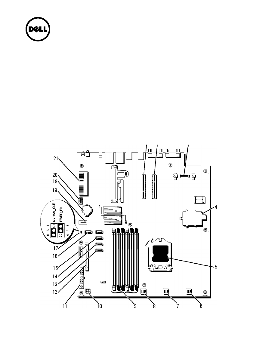
To locate the system board jumpers and connectors, see Figure 1.
Figure 1. System Board Jumpers Location
Page 2

Table 1. System Board Jumpers and Connectors
Item Connector Description
10
11
12
13
14
15
16
17
18
19
RISER2
RISER1
iDRAC6 Enterprise
iDRAC6 Express
CPU
FAN1
FAN2
FAN3
5
3
1
6
4
2
12 V
PWR_CONN
CTRL_PNL
SATA_A
SATA_B
SATA_C
SATA_D
PWRD_EN
NVRAM_CLR
USB_CONN
BATTERY
Control panel USB interface connector
SATA A connector
iDRAC6 Enterprise card connector
iDRAC6 Express card connector
Processor socket
System fan 1 connector
System fan 2 connector
System fan 3 connector
Memory module slot 5
Memory module slot 3
Memory module slot 1 (white release
lever)
Memory module slot 6
Memory module slot 4
Memory module slot 2 (white release
lever)
4-pin power connector
24-pin power connector
Control panel connector
SATA connector A
SATA connector B
SATA connector C
SATA connector D
Password enable jumper
NVRAM clear jumper
Internal USB connector
Battery socket
Page 3

Table 1. System Board Jumpers and Connectors
Item Connector Description
20 HD_ACT_CARD Expansion-card cable connector
21 PCIE-G2-X4 Internal storage controller card connector
© 2012 Dell Inc.
Trademarks used in this text: Dell™, the DELL logo, and PowerEdge™ are trademarks of Dell Inc.
2012 - 06 Rev. A00
Page 4

 Loading...