

Page 1

Dell™ PowerEdge™ Cluster FE100/FL100 Datacenter Server
USER’S GUIDE
www.dell.com
support.dell.com
Page 2
Notes, Notices, Cautions, and Warnings
Throughout this guide, blocks of text may be accompanied by an icon and printed in
bold type or in italic type. These blocks are notes, notices, cautions, and warnings,
and they are used as follows:
NOTE: A NOTE indicates important information that helps you make better use of
your computer system.
NOTICE: A NOTICE indicates either potential damage to hardware or loss
of data and tells you how to avoid the problem.
CAUTION: A CAUTION indicates a potentially hazardous situation which, if
not avoided, may result in minor or moderate injury.
WARNING: A WARNING indicates a potentially hazardous situation which,
if not avoided, could result in death or serious bodily injury.
____________________
Information in this document is subject to change without notice.
© 2001 Dell Computer Corporation. All rights reserved.
Reproduction in any manner whatsoever without the written permission of Dell Computer Corporation is strictly forbidden.
Trademarks used in this text: Dell, the DELL logo, PowerEdge, PowerVault, and Dell OpenManage
are trademarks of Dell Computer Corporation; ClusterX is a registered trademark and VERITAS is
a trademark of VERITAS Corporation; Microsoft, Windows NT, and Windows are registered trade-
marks of Microsoft Corporation; Intel and Pentium are registered trademarks of Intel Corporation;
Computer Associates and ARCserve are registered trademarks of Computer Associates International, Inc.
Other trademarks and trade names may be used in this document to refer to either the entities
claiming the marks and names or their products. Dell Computer Corporation disclaims any proprietary interest in trademarks and trade names other than its own.
April 2001 P/N 9E926 Rev. A00
Page 3

Preface
This guide provides information about the Dell PowerEdge Cluster FE100/FL100
Datacenter Server solution. This information includes procedures for installing, configuring, and troubleshooting the hardware and software components of PowerEdge
Cluster FE100/FL100 Datacenter Server configurations.
The chapters and appendixes in this guide are summarized as follows:
• Chapter 1, “Getting Started,” provides an overview of PowerEdge Cluster
FE100/FL100 Datacenter Server.
• Chapter 2, “Installation Overview,” provides an overview of the installation pro-
cess for PowerEdge Cluster FE100/FL100 Datacenter Server configurations.
Procedures are located throughout this guide.
• Chapter 3, “Preparing PowerEdge and PowerVault Systems for Clustering“pro-
vides information on adding peripherals and Fibre Channel host bus adapters.
• Chapter 4, “Cabling the Cluster Hardware,“provides instructions for properly
cabling the system hardware components.
• Chapter 5, “Configuring Storage Systems (Low-Level Configuration),“provides
information for configuring software and external shared storage.
• Chapter 6, “Configuring the System Software“provides the software configura-
tion options necessary for setting up the cluster.
• Chapter 7, “Installing Cluster Management and Systems Management Soft-
ware,“provides information on software tools for configuring and administering a
cluster including how to run Cluster Administrator locally on a cluster node and
how to install it on a remote console.
• Chapter 8, “Upgrading Your PowerEdge System to a Cluster Configuration,“pro-
vides procedures for upgrading your noncluster system to a PowerEdge Cluster
FE100/FL100 Datacenter Server configuration if the components of the cluster
hardware are already present.
• Chapter 9, “Maintaining the Cluster“provides information on maintaining
PowerEdge Cluster FE100/FL100 Datacenter Server configurations.
• Chapter 10, “SAN Components,” provides detailed information on storage area
network (SAN)-attached cluster configurations for the Dell PowerEdge Cluster
FE100/FL100 Datacenter Server configuration.
v
Page 4

• Appendix A, “Troubleshooting,” provides information to help you troubleshoot
problems with installing and configuring clusters.
• Appendix B, “Cluster Data Sheets,” provides worksheets on which to record
your specific configurations.
Warranty and Return Policy Information
Dell Computer Corporation (“Dell”) manufactures its hardware products from parts and
components that are new or equivalent to new in accordance with industry-standard
practices. See your Dell PowerEdge System Information document for complete war-
ranty information for your system.
Other Documents You May Need
You may need to refer to the following documentation when performing the procedures in this guide:
• The Dell PowerVault SAN documentation for more information on storage area
networks.
• The User's Guide for your system, which describes system features and technical
specifications, small computer system interface (SCSI) device drivers, the
System Setup program, software support, and the system configuration utility.
• The Installation and Service Guide for your PowerVault storage system, which
provides installation and operation instructions for the PowerVault 65xF storage
system.
• The Dell OpenManage Data Agent Installation and Operation Guide, the Dell
OpenManage Data Supervisor Installation and Operation Guide, the Dell
OpenManage Data Administrator Installation and Operation Guide, and the Dell
OpenManage ATF Installation and Operation Guide, which provide installation
instructions for the Dell OpenManage Data Agent, Dell OpenManage Data Supervisor, Dell OpenManage Data Administrator, and the Dell OpenManage ATF.
You may also have one or more of the following documents:
• The Rack Installation Guide for your PowerVault storage system and the rack
installation documentation for your Dell PowerEdge servers provide detailed
instructions for installing the cluster components in a rack.
• Dell OpenManage Cluster Assistant With ClusterX Getting Started Guide
provides installation and configuration instructions for the ClusterX software.
• The Hardware Installation Guide for the QLA2x00 and the Software Installation
Guide for the QLA2x00 provide installation instructions for the QLogic host bus
adapter.
• The Dell PowerVault Storage Area Network (SAN) Administrator’s Guide for
information on installing the QLogic software.
vi
Page 5

• Dell PowerEdge Expandable RAID Controller Battery Backup Module User's
Guide.
• The Microsoft Cluster Server Administrator's Guide for the Windows 2000
Cluster Service documentation describes the clustering software used on
PowerEdge Cluster FE100/FL100 Datacenter.
• The Microsoft Windows 2000 Datacenter Server documentation describes how
to install (if necessary), configure, and use the Windows 2000 Datacenter Server
operating system.
Documentation is included with any options you purchase separately from the system. This documentation includes information that you need to configure and install
these options in the Dell computer.
Technical information files-sometimes called “readme” files-may be installed on the
hard-disk drive to provide last-minute updates about technical changes to the system
or advanced technical reference material intended for experienced users or
technicians.
NOTE: Documentation updates are sometimes included with your system to describe
changes to your system or software. Always read these updates before consulting
any other documentation because the updates often contain the latest information.
Also consult Dell's Web site at http://www.support.com for updates.
Typographical Conventions
The following list defines (where appropriate) and illustrates typographical conventions used as visual cues for specific elements of text throughout this document:
• Interface components are window titles, button and icon names, menu names
and selections, and other options that appear on the monitor screen or display.
They are presented in bold.
Example: Click OK.
• Keycaps are labels that appear on the keys on a keyboard. They are enclosed in
angle brackets.
Example: <Enter>
• Key combinations are series of keys to be pressed simultaneously (unless other-
wise indicated) to perform a single function.
Example: <Ctrl ><Alt><Enter>
• Commands presented in lowercase bold are for reference purposes only and are
not intended to be typed when referenced.
Example: “Use the format command to . . . .“
• In contrast, commands presented in the Courier New font are part of an instruc-
tion and intended to be typed.
Example: “Type format a: to format the diskette in drive A.”
vii
Page 6

• Filenames and directory names are presented in lowercase bold.
Examples: autoexec.bat and c:\windows
• Syntax lines consist of a command and all its possible parameters. Commands
are presented in lowercase bold; variable parameters (those for which you substitute a value) are presented in lowercase italics; constant parameters are
presented in lowercase bold. The brackets indicate items that are optional.
Example: del [drive:] [path] filename [/p]
• Command lines consist of a command and may include one or more of the com-
mand's possible parameters. Command lines are presented in the Courier New
font.
Example: del c:\myfile.doc
• Screen text is a message or text that you are instructed to type as part of a com-
mand (referred to as a command line). Screen text is presented in the Courier
New font.
Example: The following message appears on your screen:
• No boot device available
Example: “Type md c:\Programs and press <Enter>.”
• Variables are placeholders for which you substitute a value. They are presented in
italics.
Example: DIMM_x (where x represents the DIMM socket designation).
viii
Page 7

Contents
Chapter 1 Getting Started . . . . . . . . . . . . . . . . . . . . . . . . . . . . . . 1-1
Overview of Microsoft Windows 2000 Datacenter Server . . . . . . . . . . . . . . . . . . . 1-1
Overview of a Dell PowerEdge Cluster FE100/FL100
Datacenter Server Configuration . . . . . . . . . . . . . . . . . . . . . . . . . . . . . . . . . . . . . . . 1-2
SAN-Attached Cluster Configuration . . . . . . . . . . . . . . . . . . . . . . . . . . . . . . . . 1-3
PowerEdge Cluster FE100/FL100 Identification . . . . . . . . . . . . . . . . . . . . . . . . . . . 1-4
Activen/Active and Activen/Passive Configurations . . . . . . . . . . . . . . . . . . . . . 1-5
Failover and Failback Support. . . . . . . . . . . . . . . . . . . . . . . . . . . . . . . . . . . . . . 1-6
PowerEdge Cluster FE100/FL100
Datacenter Server Failover Options. . . . . . . . . . . . . . . . . . . . . . . . . . . . . . . . . . . . . 1-6
N+1 Failover. . . . . . . . . . . . . . . . . . . . . . . . . . . . . . . . . . . . . . . . . . . . . . . . . . . 1-6
Multiway Failover. . . . . . . . . . . . . . . . . . . . . . . . . . . . . . . . . . . . . . . . . . . . . . . 1-7
Cascading Failover . . . . . . . . . . . . . . . . . . . . . . . . . . . . . . . . . . . . . . . . . . . . . . 1-8
N-Way Migration . . . . . . . . . . . . . . . . . . . . . . . . . . . . . . . . . . . . . . . . . . . . . . . 1-9
PowerEdge Cluster FE100/FL100
Datacenter Server Minimum System Requirements . . . . . . . . . . . . . . . . . . . . . . 1-11
Cluster Nodes. . . . . . . . . . . . . . . . . . . . . . . . . . . . . . . . . . . . . . . . . . . . . . . . . 1-11
Cluster Storage. . . . . . . . . . . . . . . . . . . . . . . . . . . . . . . . . . . . . . . . . . . . . . . . 1-11
Cluster Interconnect Connections
(Private Network) . . . . . . . . . . . . . . . . . . . . . . . . . . . . . . . . . . . . . . . . . . . . . . 1-11
Cluster Client Network Connections
(Public Network). . . . . . . . . . . . . . . . . . . . . . . . . . . . . . . . . . . . . . . . . . . . . . . 1-12
Operating System and System Management Software . . . . . . . . . . . . . . . . 1-12
PowerEdge Cluster FE100/FL100
Datacenter Server Support Configuration Requirements . . . . . . . . . . . . . . . . . . . 1-13
Required Configuration Requirements for the PowerEdge Cluster
FE100/FL100 Datacenter Server . . . . . . . . . . . . . . . . . . . . . . . . . . . . . . . . . . 1-13
Shared Storage Requirements for the PowerEdge Cluster
FE100/FL100 Datacenter Server Configuration . . . . . . . . . . . . . . . . . . . . . . . 1-14
SAN-Attached Cluster Requirements. . . . . . . . . . . . . . . . . . . . . . . . . . . . . . . 1-15
ix
Page 8

Chapter 2 Installation Overview . . . . . . . . . . . . . . . . . . . . . . . . . 2-1
Chapter 3 Preparing PowerEdge and
PowerVault Systems for Clustering . . . . . . . . . . . . . . . 3-1
Adding Peripherals to Your Cluster . . . . . . . . . . . . . . . . . . . . . . . . . . . . . . . . . . . . . 3-1
Configuring Fibre Channel HBAs on Separate PCI Buses . . . . . . . . . . . . . . . . 3-2
Configuring PowerVault DPE and DAE Enclosure Addresses . . . . . . . . . . . . . 3-2
Chapter 4 Cabling the Cluster Hardware . . . . . . . . . . . . . . . . . . 4-1
Cluster Cabling Components . . . . . . . . . . . . . . . . . . . . . . . . . . . . . . . . . . . . . . . . . 4-1
Fibre Channel Copper Connectors . . . . . . . . . . . . . . . . . . . . . . . . . . . . . . . . . . . . . 4-2
Cabling Your Public Network. . . . . . . . . . . . . . . . . . . . . . . . . . . . . . . . . . . . . . . . . . 4-3
Using NICs in Your Public Network . . . . . . . . . . . . . . . . . . . . . . . . . . . . . . . . . 4-3
Cabling Your Private Network . . . . . . . . . . . . . . . . . . . . . . . . . . . . . . . . . . . . . . . . . 4-3
Using Broadcom NetExtreme Gigabit Ethernet Controllers in
Your Private Network. . . . . . . . . . . . . . . . . . . . . . . . . . . . . . . . . . . . . . . . . . . . 4-3
Using Giganet cLAN for the Private Network . . . . . . . . . . . . . . . . . . . . . . . . . 4-4
Protecting Your Cluster From Power Failure. . . . . . . . . . . . . . . . . . . . . . . . . . . . . . 4-5
Connecting Standby Power Supplies in the PowerVault System . . . . . . . . . . 4-5
Cabling Your Mouse, Keyboard, and
Monitor in a Dell Rack. . . . . . . . . . . . . . . . . . . . . . . . . . . . . . . . . . . . . . . . . . . . . . . 4-6
Chapter 5 Configuring Storage Systems
(Low-Level Configuration). . . . . . . . . . . . . . . . . . . . . . 5-1
Configuring PowerVault Shared Storage Hard-Disk Drives . . . . . . . . . . . . . . . . . . . 5-1
Configuring the LUNs and RAID Level for the Shared Storage Subsystem . . 5-2
Configuring Internal SCSI Hard-Disk Drives. . . . . . . . . . . . . . . . . . . . . . . . . . . 5-2
RAID Level for the Internal SCSI Hard-Disk Drives . . . . . . . . . . . . . . . . . . . . . 5-2
Chapter 6 Configuring the System Software . . . . . . . . . . . . . . . . 6-1
Preparing for Microsoft Windows 2000 Datacenter Server Installation . . . . . . . . . 6-1
Configuring the Cluster Nodes in a
Windows 2000 Domain. . . . . . . . . . . . . . . . . . . . . . . . . . . . . . . . . . . . . . . . . . . . . . 6-2
Configuring the Windows 2000 Cluster Service . . . . . . . . . . . . . . . . . . . . . . . . . . . 6-3
Configuring the Public and Private Networks . . . . . . . . . . . . . . . . . . . . . . . . . . . . . 6-4
Static IP Address . . . . . . . . . . . . . . . . . . . . . . . . . . . . . . . . . . . . . . . . . . . . . . . 6-4
Configuring the IP Addresses for the Private Network . . . . . . . . . . . . . . . . . . 6-5
x
Page 9

Installing and Configuring Your Windows 2000 Datacenter Server Network . . . . . 6-6
Overview of a Windows 2000 Datacenter Server Network Installation. . . . . . 6-6
Updating the Host Bus Adapter Driver. . . . . . . . . . . . . . . . . . . . . . . . . . . . . . . 6-8
Installing the Dell OpenManage Storage Management Software
for the PowerVault Storage System. . . . . . . . . . . . . . . . . . . . . . . . . . . . . . . . . 6-9
Configuring Shared Drives Using the Windows 2000
Disk Management Tool . . . . . . . . . . . . . . . . . . . . . . . . . . . . . . . . . . . . . . . . . 6-11
Assigning Drive Letters and Formatting Drives
on the Shared Storage System . . . . . . . . . . . . . . . . . . . . . . . . . . . . . . . . 6-11
Using the Windows 2000 Dynamic Disks and Volumes. . . . . . . . . . . . . 6-12
Verifying Cluster Readiness. . . . . . . . . . . . . . . . . . . . . . . . . . . . . . . . . . . . . . . . . . 6-13
Installing and Configuring the Windows 2000 Cluster Service . . . . . . . . . . . 6-13
Cluster Quorum Resource . . . . . . . . . . . . . . . . . . . . . . . . . . . . . . . . . . . 6-13
Cluster Resource Group . . . . . . . . . . . . . . . . . . . . . . . . . . . . . . . . . . . . . 6-14
Adding Additional Applications and Data to the Quorum Disk . . . . . . . . 6-14
Verifying Cluster Functionality . . . . . . . . . . . . . . . . . . . . . . . . . . . . . . . . . . . . 6-15
Verifying Cluster Service . . . . . . . . . . . . . . . . . . . . . . . . . . . . . . . . . . . . . . . . 6-15
Verifying Cluster Resource Availability. . . . . . . . . . . . . . . . . . . . . . . . . . . . . . 6-15
Configuring the Dell OpenManage
Manage Node (Data Agent) for a Cluster Environment . . . . . . . . . . . . . . . . . . . . . 6-16
Configuring the Data Agent for Cluster Failover . . . . . . . . . . . . . . . . . . . . . . . . . . 6-16
Configuring Failover and Failback Support. . . . . . . . . . . . . . . . . . . . . . . . . . . . . . . 6-18
Failover Support Through Four-Node Clustering . . . . . . . . . . . . . . . . . . . . . . 6-18
Modifying the Failover Sequence of the Disk Groups. . . . . . . . . . . . . . . 6-19
Chapter 7 Installing Cluster Management
and Systems Management Software . . . . . . . . . . . . . 7-1
Microsoft Cluster Administrator . . . . . . . . . . . . . . . . . . . . . . . . . . . . . . . . . . . . . . . 7-1
Running Cluster Administrator on a Cluster Node . . . . . . . . . . . . . . . . . . . . . . 7-1
Installing Cluster Administrator on a Remote Console Running
Windows 2000 Professional. . . . . . . . . . . . . . . . . . . . . . . . . . . . . . . . . . . . . . . 7-1
Installing the Cluster Administrator on a Remote Console Running
Windows 2000 Advanced Server or Server Editions . . . . . . . . . . . . . . . . . . . . 7-2
Installing Cluster Administrator for Windows 2000 on a Remote Console
Running Windows NT 4.0 Server, Enterprise Edition. . . . . . . . . . . . . . . . . . . . 7-2
Installing Dell OpenManage Cluster Assistant With ClusterX (Optional). . . . . . . . . 7-3
Chapter 8 Upgrading Your PowerEdge
System to a Cluster Configuration . . . . . . . . . . . . . . . 8-1
Upgrading Your PowerEdge System to a PowerEdge Cluster FE100/FL100
Datacenter Server Configuration . . . . . . . . . . . . . . . . . . . . . . . . . . . . . . . . . . . . . . . 8-1
Installing the Appropriate Version of
Windows 2000 on Your PowerEdge System . . . . . . . . . . . . . . . . . . . . . . . . . . . . . 8-2
xi
Page 10

Chapter 9 Maintaining the Cluster. . . . . . . . . . . . . . . . . . . . . . . . 9-1
Connecting to Your PowerVault
Storage Systems Using Dell OpenManage Storage Management Software . . . . . 9-1
Connecting to the PowerVault Shared Storage Systems
Using Data Agent. . . . . . . . . . . . . . . . . . . . . . . . . . . . . . . . . . . . . . . . . . . . . . . 9-1
Connecting to Data Agent Using Data Administrator . . . . . . . . . . . . . . . . . . . 9-2
Identifying the Cluster Name . . . . . . . . . . . . . . . . . . . . . . . . . . . . . . . . . . 9-2
Connecting to Data Agent Using Data Supervisor. . . . . . . . . . . . . . . . . . . . . . 9-3
Identifying the Device Name of the Storage Processor . . . . . . . . . . . . . . 9-3
Restoring Communications to a Failed Storage Device Using
Dell OpenManage ATF. . . . . . . . . . . . . . . . . . . . . . . . . . . . . . . . . . . . . . . . . . . 9-3
Using the QLogic Fibre Channel Configuration Software for PowerVault
65xF Storage Processor Replacement . . . . . . . . . . . . . . . . . . . . . . . . . . . . . . . . . . 9-4
Determining the RAID Levels of the Shared Disk Volumes . . . . . . . . . . . . . . . . . . 9-4
Configuring Your Cluster Nodes Using
Windows 2000 Datacenter Server . . . . . . . . . . . . . . . . . . . . . . . . . . . . . . . . . . . . . 9-5
Adding a Third NIC to a Cluster Node . . . . . . . . . . . . . . . . . . . . . . . . . . . . . . . 9-5
Changing the IP Address of a Cluster Node . . . . . . . . . . . . . . . . . . . . . . . . . . 9-7
Uninstalling Cluster Service . . . . . . . . . . . . . . . . . . . . . . . . . . . . . . . . . . . . . . . 9-8
Running chkdsk /f on a Quorum Disk . . . . . . . . . . . . . . . . . . . . . . . . . . . . . . . 9-8
Replacing a Cluster Node. . . . . . . . . . . . . . . . . . . . . . . . . . . . . . . . . . . . . . . . . 9-8
Chapter 10 SAN Components . . . . . . . . . . . . . . . . . . . . . . . . . . . . 10-1
Overview of a PowerVault SAN . . . . . . . . . . . . . . . . . . . . . . . . . . . . . . . . . . . . . . 10-1
PowerVault SAN Components for PowerEdge Cluster
FE100/FL100 Datacenter Server Configurations . . . . . . . . . . . . . . . . . . . . . . 10-1
SAN-Attached Clusters . . . . . . . . . . . . . . . . . . . . . . . . . . . . . . . . . . . . . . . . . . . . . 10-2
Fibre Channel Fabrics . . . . . . . . . . . . . . . . . . . . . . . . . . . . . . . . . . . . . . . 10-3
Attaching a SAN-Attached Cluster Configuration to a Network . . . . . . . 10-4
Using Dell PowerVault Fibre Channel Switches . . . . . . . . . . . . . . . . . . . . . . . . . . 10-6
Attaching a PowerVault Storage System to a SAN-Attached Cluster . . . . . . . . . . 10-6
Connecting the PowerEdge Cluster to a Single PowerVault
Storage System . . . . . . . . . . . . . . . . . . . . . . . . . . . . . . . . . . . . . . . . . . . . . . . 10-6
Connecting a PowerVault 130T DLT Library and PowerVault 35F
Fibre Channel Bridge to a Cluster-Attached PowerVault SAN . . . . . . . . . . . . 10-7
Configuring Hard-Disk Drive Letters Using Multiple
Shared Storage Units. . . . . . . . . . . . . . . . . . . . . . . . . . . . . . . . . . . . . . . . . . . 10-7
Additional PowerEdge Cluster Maintenance Procedures . . . . . . . . . . . . . . . . . . . 10-8
Using the QLogic Fibre Channel Configuration Utility
for Storage Processor Failure. . . . . . . . . . . . . . . . . . . . . . . . . . . . . . . . . . . . . 10-8
Appendix A Troubleshooting. . . . . . . . . . . . . . . . . . . . . . . . . . . . . . A-1
Troubleshooting Windows 2000 . . . . . . . . . . . . . . . . . . . . . . . . . . . . . . . . . . . . . . . A-2
xii
Page 11

Appendix B Cluster Data Sheets. . . . . . . . . . . . . . . . . . . . . . . . . . . B-1
PowerEdge Cluster FE100/FL100
Datacenter Server Configuration Matrix . . . . . . . . . . . . . . . . . . . . . . . . . . . . . . . . . B-1
Cluster Data Sheets. . . . . . . . . . . . . . . . . . . . . . . . . . . . . . . . . . . . . . . . . . . . . . . . . B-3
Index
Figures Figure 1-1. SAN-Attached Cluster Configuration . . . . . . . . . . . . . . . . . . . . . . . . . 1-4
Figure 1-2. N+1 Failover. . . . . . . . . . . . . . . . . . . . . . . . . . . . . . . . . . . . . . . . . . . . 1-7
Figure 1-3. Example of a 4-Node Multiway Failover . . . . . . . . . . . . . . . . . . . . . . 1-8
Figure 1-4. Example of a 4-Node Cascading Failover. . . . . . . . . . . . . . . . . . . . . . 1-9
Figure 1-5. Example of a 4-Node N-Way Migration Solution . . . . . . . . . . . . . . . 1-10
Figure 4-1. DB-9 Connector . . . . . . . . . . . . . . . . . . . . . . . . . . . . . . . . . . . . . . . . . 4-2
Figure 4-2. HSSDC Connector . . . . . . . . . . . . . . . . . . . . . . . . . . . . . . . . . . . . . . . 4-2
Figure 4-3. Configuration Using a Broadcom NetExtreme Gigabit NICs
for the Private Network . . . . . . . . . . . . . . . . . . . . . . . . . . . . . . . . . . . 4-4
Figure 4-4. Configuration Using a GigaNet cLAN NIC
for the Private Network . . . . . . . . . . . . . . . . . . . . . . . . . . . . . . . . . . . 4-5
Figure 4-5. Cable Configuration of PowerVault 65xF Power Supplies . . . . . . . . . 4-6
Figure 10-1. SAN-Attached Cluster Configuration . . . . . . . . . . . . . . . . . . . . . . . . 10-3
Figure 10-2. SAN-attached Clusters Using a Public, Private,
and SAN Network . . . . . . . . . . . . . . . . . . . . . . . . . . . . . . . . . . . . . . 10-5
Tables Table 2-1. System-Setup Navigation Keys . . . . . . . . . . . . . . . . . . . . . . . . . . . . . 2-2
Table 2-2. Device-List Screen Navigation Keys . . . . . . . . . . . . . . . . . . . . . . . . . 2-7
Table 2-3. Power Time-Out Periods . . . . . . . . . . . . . . . . . . . . . . . . . . . . . . . . . 2-10
Table 3-1. ICU Keys . . . . . . . . . . . . . . . . . . . . . . . . . . . . . . . . . . . . . . . . . . . . . . 3-4
Table 5-1. System-Board Jumper Settings. . . . . . . . . . . . . . . . . . . . . . . . . . . . . 5-7
Table 5-2. System Board and Riser Board Connectors and Sockets . . . . . . . . . 5-8
Table 6-1. Sample DIMM Configuration Options . . . . . . . . . . . . . . . . . . . . . . . . 6-4
Table A-1. Technical Specifications. . . . . . . . . . . . . . . . . . . . . . . . . . . . . . . . . . . A-1
Table B-1. Configuration Utility Messages . . . . . . . . . . . . . . . . . . . . . . . . . . . . . B-1
Table B-2. Configuration Manager Messages. . . . . . . . . . . . . . . . . . . . . . . . . . . B-5
xiii
Page 12

xiv
Page 13

CHAPTER 1
Getting Started
This chapter provides an overview of the following information for the
™
PowerEdge™ Cluster FE100/FL100 Datacenter Server configuration:
Dell
• Microsoft
®
Windows® 2000 Datacenter Server operating system
• Configuration and operation
• Cluster identification
• Failover options
• Minimum system requirements
• Support configuration requirements
Overview of Microsoft Windows 2000
Datacenter Server
Windows 2000 Datacenter Server is geared specifically for organizations implementing and managing enterprise applications that require high availability and high
performance. Typical application usages include large data warehouses, server consolidation, online transaction processing (OLTP), and modeling/simulation.
Windows 2000 Datacenter Server provides all of the features included with Microsoft
Windows 2000 Advanced Server, along with the following additional features:
• Two-to-four-node clustering—provides high availability of applications through
failover to another node in the cluster
• Support for up to 32-way symmetrical multiprocessing (SMP)—the operating sys-
tem distributes the processing workload with up to 32 central processing units
(CPUs)
• Support for up to 32 gigabyte (GB) random access memory (RAM) on the physi-
cal address extension (PAE)-capable PowerEdge 8450 system—improves
multiple application performance
• Winsock Direct—optimizes Internet protocol (IP) performance
• Process Control management tool—improves server resource management
support.dell.com Getting Started 1-1
Page 14

NOTE: Since Datacenter Server is one of four operating systems in the
Windows 2000 platform, some of the core services incorporated within Datacenter
Server are common to all Windows 2000 platforms. In the following sections, “Windows 2000” is used to identify the services common to all Windows 2000 platforms
and “Windows 2000 Datacenter Server” is used to identify services and components
specific to the Datacenter Server platform.
Overview of a Dell PowerEdge Cluster
FE100/FL100 Datacenter Server
Configuration
The PowerEdge Cluster FE100/FL100 Datacenter Server is a cluster solution that
implements 2-node to 4-node clustering technology based on the Microsoft
Windows 2000 Cluster Service (MSCS) software incorporated within the Windows
2000 Datacenter Server operating system.
NOTE: In this guide and in other cluster documentation, MSCS is also referred to as
Cluster Service.
PowerEdge Cluster FE100/FL100 Datacenter Server solutions provide the following
benefits in meeting the needs of mission-critical network application programs:
• High availability of system services and resources to network clients
• Redundant storage for application program data
• Failure recovery for cluster application programs
• Flexible maintenance capabilities, allowing you to repair, maintain, or upgrade a
cluster node without taking the entire cluster offline
• Load balancing between the cluster nodes
A PowerEdge cluster consists of two or more PowerEdge 8450 server systems
(referred to as cluster nodes) that are interconnected with hardware and software
components, providing a single point of continuous access to network services
(including file systems, databases, enterprise resource planning [ERP], and other
application programs, and services) for network clients. Each cluster node is configured with software, storage, and network resources that enable it to monitor and
interact with the other nodes to provide mutually redundant operation. Because the
cluster nodes interact in this way, they appear as a single system to the network
clients.
In a standard client/server environment, a user accesses a network resource by connecting to a physical server with a unique Internet Protocol (IP) address and network
name. If the server fails for any reason, the user will no longer be able to access the
resource. In a cluster environment, a user does not access a physical server, but a vir-
tual server—a network resource managed by the Cluster Service that is not
associated with a physical server, and can failover to another cluster node. Virtual
servers are designed to dynamically reconfigure user resources during a connection
or hardware failure, providing a higher availability of network resources as compared
to a nonclustered PowerEdge system.
1-2 User’s Guide
Page 15

NOTE: For more information on failover, failback, and groups, see “Configuring
Failover and Failback Support” in Chapter 6, “Configuring the System Software.”
SAN-Attached Cluster Configuration
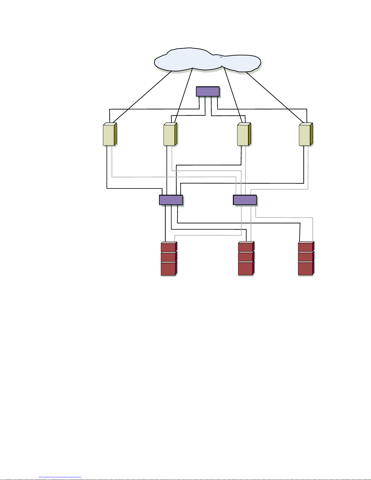
A PowerEdge Cluster FE100/FL100 Datacenter Server configuration is a SAN-attached
cluster configuration where all four cluster nodes are attached to a single
PowerVault™ storage system or to multiple PowerVault storage systems through a
Dell PowerVault SAN using a redundant Fibre Channel switch fabric.
NOTE: A PowerEdge Cluster FE100/FL100 Datacenter Server configuration cannot
coexist on the Fibre Channel switch fabric with other clusters or stand-alone servers.
A Fibre Channel switch fabric is an active, intelligent, and private connection of one or
more fibre channel switches that provide high-speed, point-to-point connections
between servers and storage devices. Using instructions that are programmed into
the switch, the switches in a Fibre Channel fabric provide point-to-point connection
through inbound and outbound points from one device (sender) to another device or
switch (receiver) on the network. If the data is sent to another switch, the process
repeats itself until a connection is established between the sender and the receiver.
One or more PowerVault Fibre Channel switches make up a Fibre Channel fabric.
Figure 1-1 shows an advanced SAN-attached cluster configuration.
support.dell.com Getting Started 1-3
Page 16
LAN/WAN
private network switch
PowerEdge
server
PowerEdge
server
Fibre Channel
Switch
PowerVa u lt
storage
system
PowerEdge
server
PowerVa u lt
storage
system
PowerEdge
server
Fibre Channel
Switch
PowerVa u lt
storage
system
Figure 1-1. SAN-Attached Cluster Configuration
PowerEdge Cluster FE100/FL100
Identification
The Dell PowerEdge Fibre Channel clusters are configured and identified by the
private network connection (cluster interconnect) that connects the cluster nodes
together— FE (Fibre Channel Ethernet) and FL (Fibre Channel Low Latency)—and the
type of storage devices in the cluster configuration.
1-4 User’s Guide
Page 17

Table 1-1 provides an overview of the differences between PowerEdge Cluster FE100
and FL100 Datacenter Server configurations.
Table 1-1. PowerEdge Cluster FE100/FL100 Configurations
Cluster Solution Cluster Interconnect
Typ e
PowerEdge
Fast Ethernet Broadcom NetExtreme
Cluster FE100
PowerEdge
Giganet Giganet cLAN 1000
Cluster Interconnect
Network Interface
Controller (NIC)
Gigabit Ethernet NIC
Cluster FL100
Activen/Active and Activen/Passive Configurations
MSCS and PowerEdge Clusters support multiple variations of Activen/Active and
n
Active
Table 1-2 provides a description of the configuration types and their definitions.
Table 1-2. Activen/Active and Activen/Passive Configuration Types
/Passive configurations (where n = the number of active cluster nodes).
Configuration Type Number
of Active
Cluster
Nodes
Active/Active
2
Definition
The active node(s) process requests
and provide failover for each other,
Active/Active/Active
3
depending on cluster node resources
and your configuration.
Active/Active/Active/Active
4
Active/Passive
1
The active node(s) processes
requests while the passive node
Active/Active/Passive
Active/Active/Active/Passive
n
An active
/active configuration refers to a cluster with virtual servers running on each
2
waits for the active node to fail.
3
node. When an application is running on node 1, the remaining cluster nodes do not
have to wait for node 1 to fail. The remaining cluster nodes can run their own clusteraware applications (or another instance of the same application) while providing
n
failover capabilities for the resources on node 1. However, an active
/active cluster
node must be configured appropriately to handle the workload of other cluster nodes
in case one cluster node fails.
n
Active
/passive refers to failover cluster configurations in which one cluster node is
actively processing requests for a clustered application while another cluster node
n
simply waits for the active node to fail. An active
/passive configuration is more costly
in terms of price and performance because one cluster node sits idle all of the time.
support.dell.com Getting Started 1-5
Page 18

However, this configuration is appropriate for business-critical systems since the
application can use the full power of another cluster node in case one cluster node
fails.
NOTE: For clarity, future references of activen/active and activen/passive configurations will use “n” to equal the number of active cluster nodes. For example, an
active/active/active/active configuration consisting of four active cluster nodes will be
referred to as an active
4
configuration.
Failover and Failback Support
One of the key features of Cluster Service is failover and failback support. Failover is
the process of automatically moving resources from a failed cluster node to other
healthy node(s) in the cluster. Failback is the process of returning the resources back
to the original cluster node. Both failover and failback can be an automatic or manual
process, depending on how you configure the Cluster Service.
NOTE: For more information on failover, failback, and cluster groups, see “Configuring
Failover and Failback Support” in Chapter 6, “Configuring the System Software.”
PowerEdge Cluster FE100/FL100
Datacenter Server Failover Options
The PowerEdge FE100/FL100 Datacenter Server configuration provides the following
failover options:
• N + 1
• Multiway
• Cascading
• N-Way migration solution
The following subsections describe each of these failover options.
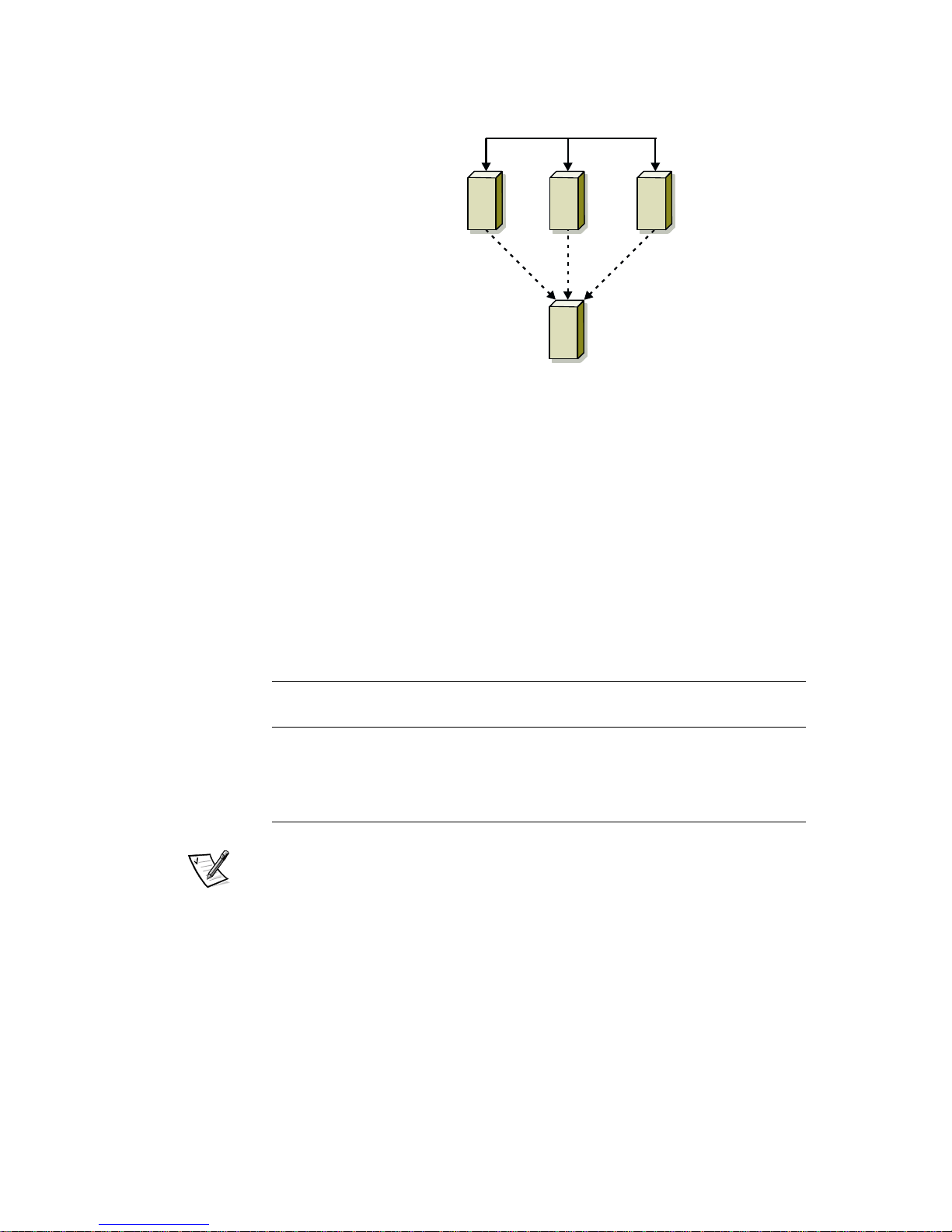
N+1 Failover
N+1 failover is an activen/passive failover solution where one cluster node provides
backup for multiple cluster nodes. This solution provides the following features:
Advantage:
• One cluster node is a dedicated backup node for all cluster nodes, providing the
best solution for critical applications.
Disadvantages
• High expense, as one node is not used to provide network resources.
• Backup cluster node may lack the resources to support multiple cluster node
failures.
Figure 1-2 shows an example of N + 1 failover configuration.
1-6 User’s Guide
Page 19
cluster
node 1
cluster
node 2
cluster
node 3
cluster
node 4
(backup)
Figure 1-2. N+1 Failover
Table 1-3 provides a N+1 failover configuration for the cluster shown in Figure 1-2. For
each cluster resource group, the failover order in the Preferred Owners list provides
the order that you want that resource group to failover. If that resource group or its
cluster node fails, the cluster will try to fail that resource group to the first available
node in the list. In this example, node 1 owns cluster resource group A, node 2 owns
cluster resource group B, and node 3 owns cluster resource group C. Cluster
resource groups A, B, or C would failover to cluster node 4, if cluster node 1, 2, or 3
fails, respectively.
Table 1-3. N+1 Failover Configuration for a 4-Node Cluster
Cluster Resource Group Failover Order in the Preferred
Owners List
A1, 4
B2, 4
C3, 4
NOTE: When implementing this type of failover solution, failback should be configured if the cluster node lacks the resources (such as memory or processing power) to
support one or more cluster node failures.
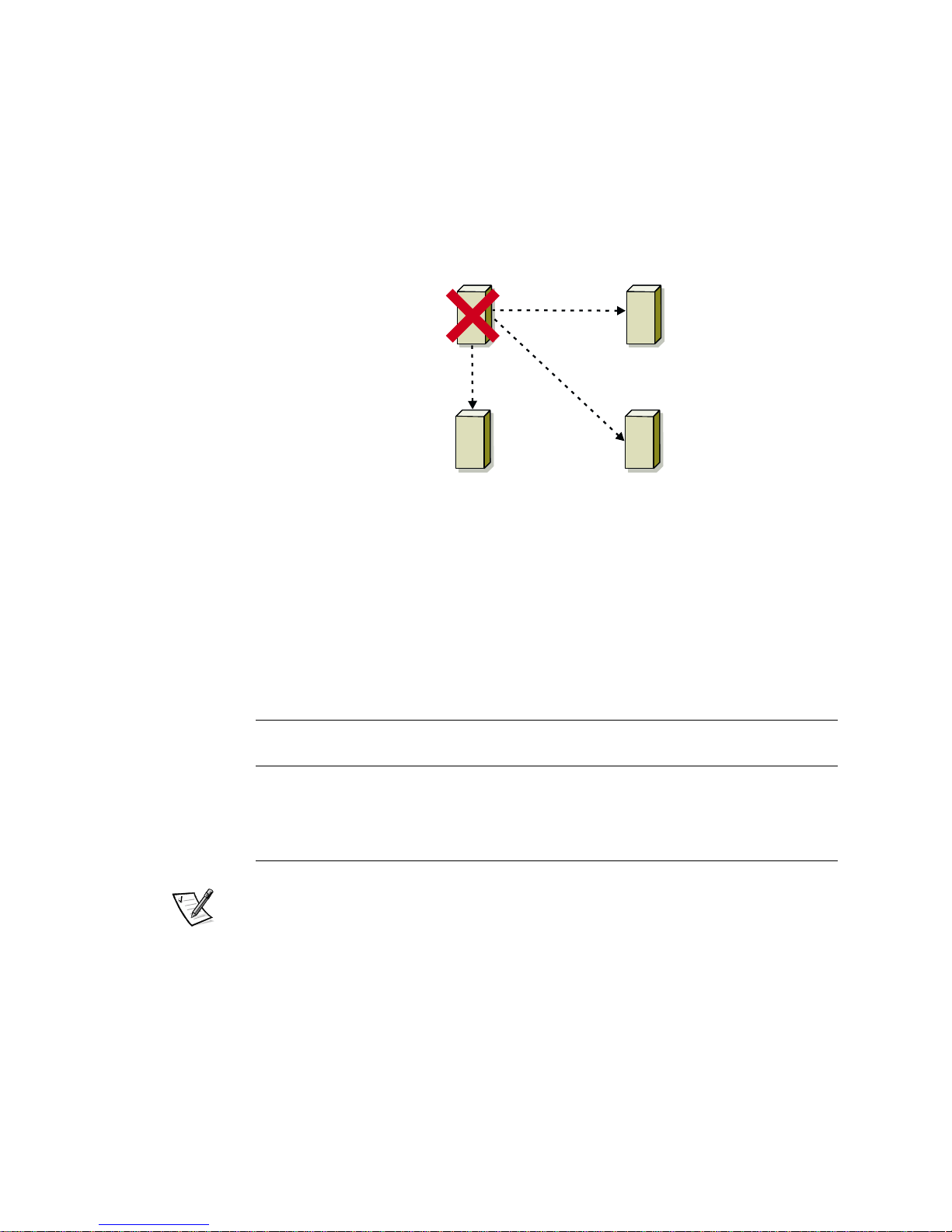
Multiway Failover
Multiway failover is an activen/active failover solution where running applications from
a failed node migrate to multiple nodes in the cluster. This active
failover provides the following features:
Advantage:
n
/active type of
• Automatic failover and load-balancing between the cluster nodes.
support.dell.com Getting Started 1-7
Page 20
Disadvantage:
• Must ensure that the failover cluster nodes have ample resources available to
handle the additional workload.
Figure 1-3 shows an example of multiway failover configuration.
cluster
node 1
Application A
Application C
cluster node 3 cluster node 4
Application B
cluster
node 2
Figure 1-3. Example of a 4-Node Multiway Failover
Table 1-4 provides an example of a multiway failover configuration for the cluster
shown in Figure 1-3. For each cluster resource group, the failover order in the
Preferred Owners list outlines the order that you want that resource group to failover.
In this example, node 1 owns cluster resource groups A, B, and C. If node 1 fails, the
cluster resource groups A, B, and C will failover to cluster nodes 2, 4, and 3, respectively. The cluster resource groups on cluster nodes 2, 3, and 4 need to be configured
similarly.
Table 1-4. Example of a 4-Node Multiway Failover Configuration
1-8 User’s Guide
Cluster Resource Group Failover Order in the
Preferred Owners List
A 1, 2, 3, 4
B 1, 4, 2, 3
C 1, 3, 4, 2
NOTE: When implementing this type of failover solution, failback should be configured to avoid performance degradation.
Cascading Failover
With Cascading failover, all running applications migrate from the failed node to the
next preassigned cluster node. If you do not make a failover selection, cascading
failover will be the default failover type. This type of failover provides the following
features:
Page 21
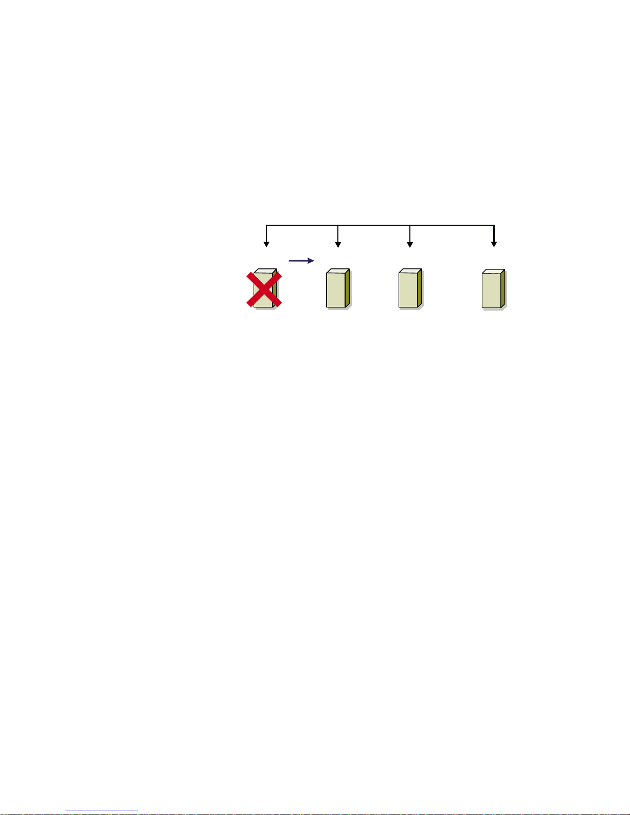
Advantage:
• High resource availability to users.
Disadvantage:
• The cluster node next in line for failover may not have ample resources available
to handle the additional workload of the failed node.
Figure 1-4 shows an example of cascading failover configuration.
applications
failed cluster
node 1
cluster
node 2
cluster
node 3
cluster
node 4
Figure 1-4. Example of a 4-Node Cascading Failover
N-Way Migration
N-Way migration is the ability to manually migrate an application from one node to any
node in the cluster (based on cluster node resource availability). This type of solution
provides the following features:
Advantages:
• Adjustable resource allocation.
• Added flexibility.
Disadvantage:
• Solution is not automatic.
Figure 1-5 shows an example of an N- Way migration solution.
support.dell.com Getting Started 1-9
Page 22
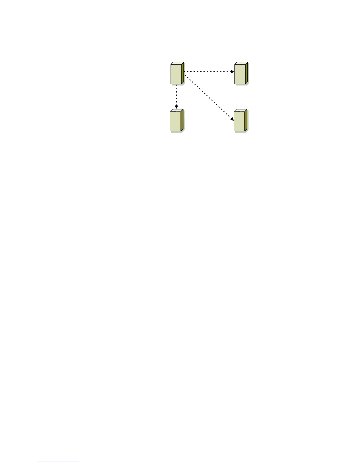
cluster
node 1
cluster
node 2
Application A
cluster
node 3
cluster
node 4
Figure 1-5. Example of a 4-Node N-Way Migration Solution
Table 1-5 provides an overview of the failover types implemented with Datacenter
Server.
Table 1-5. Failover Configurations
Failover
Type
N + 1 One server provides
Multiway Running applications
Description Advantage Disadvantage
backup for multiple
servers in the cluster
High resource availability
Backup cluster
node may lack the
resources to
support multiple
cluster node
failures
migrate to multiple
nodes in the cluster
Application load
balancing
Must ensure that
the failover cluster
nodes have ample
resources available
to handle the additional workload
Cascading Running applications
N-Way
migration
1-10 User’s Guide
migrate to the next
pre-assigned cluster
node
Any running application(s) are manually
migrated to any node
in the cluster
Higher availability The cluster node
next in line for
failover may not
have ample
resources available
to handle the additional workload of
the failed node
Added flexibility
and adjustable
Solution is not
automatic
resource
allocation
Page 23

PowerEdge Cluster FE100/FL100
Datacenter Server Minimum System
Requirements
Dell PowerEdge Cluster FE100/FL100 Datacenter Server configurations require the
following hardware and software components:
• Cluster nodes
• Cluster storage
• Cluster interconnects
• Operating system and system management software
Cluster Nodes
Cluster nodes require the following hardware resources:
• Two to four supported Dell PowerEdge systems, each with at least two
microprocessors.
• For each server, a minimum of 2 GB random access memory (RAM) and two
HBAs.
• For each server, at least one network interface controller (NIC) is required for
client local area network (LAN) connections (public network).
• One NIC required for the cluster interconnect (private network).
Cluster Storage
Cluster storage requires the following:
• For each cluster, at least one supported PowerVault 65xF/630F Fibre Channel
storage system with dual standby power supplies (SPSs).
• For each PowerVault 65xF disk processor enclosure (DPE), at least ten hard-disk
drives are required;
• Each PowerVault 630F disk array enclosure (DAE) attached to the cluster can con-
tain five or ten hard-disk drives in each DAE.
Cluster Interconnect Connections
(Private Network)
The cluster connections for the cluster interconnect (private network that connects
the cluster nodes together) requires the following hardware components:
• For each server, either a Broadcom NetExtreme Gigabit Ethernet NIC or
Giganet cLAN 1000 adapter.
• For each server, one Category 5 (CAT 5) Ethernet cable or Giganet cLAN cable to
connect the nodes.
support.dell.com Getting Started 1-11
Page 24

• For each cluster, a network switch or Giganet cLAN cluster switch to connect the
cluster nodes.
NOTE: If you have a two-node PowerEdge Cluster FE100/FL100 Datacenter Server
configuration that will not expand the configuration to a three or four node cluster, a
crossover cable or cLAN cable can be used to connect the nodes rather than using a
private network switch.
Cluster Client Network Connections
(Public Network)
The cluster connections to the client network (public network for client access of
cluster resources) requires the following hardware components:
• For each server, a Broadcom NetExtreme Gigabit Ethernet NIC or
®
PRO/1000 Gigabit Server Adapter.
Intel
Operating System and System Management Software
Dell PowerEdge Cluster FE100 and FL100 Datacenter Server systems require the
following operating system and system management software:
• Microsoft Windows 2000 Datacenter Server
NOTE: One licensed copy of Windows 2000 Datacenter Server is required for
each cluster node.
• QLogic Fibre Channel Configuration Utility
• Dell OpenManage Application Transparent Failover
• Dell OpenManage Managed Node (Data Agent)
• Dell OpenManage Data Administrator or Dell OpenManage Data Supervisor
• Dell OpenManage Cluster Assistant With ClusterX 3.0.1 with Service Pack 2 or
later (optional)
1-12 User’s Guide
Page 25

PowerEdge Cluster FE100/FL100
Datacenter Server Support Configuration
Requirements
The following tables provide configuration information for the following cluster components and configurations:
• Cluster nodes
• Shared storage systems
• SAN-attached clusters
Required Configuration Requirements for the PowerEdge
Cluster FE100/FL100 Datacenter Server
Table 1-6 provides the cluster component requirements for a PowerEdge Cluster
FE100/FL100 Datacenter Server configuration.
Table 1-6. Cluster Node Requirements
Rule/Guideline Description
Platform Microsoft Windows 2000 Datacenter Server with
two to four homogeneous PowerEdge 8450 systems with basic input/output system (BIOS) version
A04 per cluster
Processors
Memory (RAM) Minimum of 2 GB up to 32 GB random access
Host bus adapters (HBA) Two identical QLogic 2200/66 HBAs per cluster
Internal hard-disk drives Minimum of two logical drives with a minimum of
Cluster interconnect
(private network)
Two to eight Pentium
central processing units (CPU) with 2 megabytes
(MB) of cache per system
memory (RAM) per system
node.
Both copper and Fibre Channel HBAs are supported.
9 GB storage on each logical volume
• Giganet cLAN with card level A01 and driver
version 4.1.1
®
III 700 megahertz (MHz)
• Broadcom NetExtreme Gigabit Ethernet NIC
with driver version 1.29.0.0
Public network
• Intel PRO/1000 Gigabit Server Adapter with
driver version 2.19.219.0
• Broadcom NetExtreme Gigabit Ethernet NIC
with driver version 1.29.0.0
support.dell.com Getting Started 1-13
Page 26

Table 1-6. Cluster Node Requirements (continued)
Rule/Guideline Description
RAID controller One PowerEdge Expandable RAID controller 2/DC
(PERC 2/DC) with firmware version 1.01 and driver
version 2.62
Cluster management
(optional)
Remote ser ver
management (optional)
Operating systems Microsoft Windows 2000 Datacenter Server with
Dell OpenManage™ Cluster Assistant With
ClusterX
Dell OpenManage Remote Assistant Card (DRAC)
with firmware version 2.3 and driver version 2.3.0.4
the latest Service Pack and hotfixes
(one licensed copy per cluster node)
®
, version 3.0.1 with Service Pack 2 or later
Shared Storage Requirements for the PowerEdge Cluster
FE100/FL100 Datacenter Server Configuration
Table 1-7 provides the clustering requirements for the PowerEdge Cluster FE100/
FL100 Datacenter Server.
Table 1-7. PowerEdge Cluster FE100/FL100 Shared Storage
Requirements
Rule/Guideline Description
Disk array PowerVault 650F with firmware version 5.11.09
Storage processors Two identical PowerVault storage processors, each
with a minimum of 2 GB RAM
1-14 User’s Guide
Standby power supplies Dual standby power supplies required
Supported RAID levels RAID 0, RAID 1, RAID 3, RAID 5, and RAID 1/0
Tape library (optional) PowerVault 130T digital linear tape (DLT) library with
driver version 1.0
NOTICE: Dell recommends that you use a redundant array of independent
disks (RAID) level other than RAID 0 for your PowerVault shared storage
system. RAID 0 does not provide the level of availability required for the
quorum resource. See the Installation and Troubleshooting Guide for your
PowerVault storage system for more information about setting up RAID levels for the system.
Page 27

SAN-Attached Cluster Requirements
Table 1-8 provides the requirements for a SAN-attached cluster configuration.
Table 1-8. SAN-Attached Cluster Requirements
Rule/Guideline Description
SAN version SAN 3.0
HBA QLogic QLA2200/66 with firmware version 1.45 and
driver version 7.04.08.02
HBA failover driver Dell OpenManage ATF version 2.3.2.5
Fibre Channel switch PowerVault 51F Fibre Channel switch with firmware
version 2.1.7
PowerVault 56F Fibre Channel switch with firmware
version 2.1.7
Fibre Channel-to-SCSI
bridge
Up to four PowerVault 35F Fibre Channel-to-SCSI
bridges with firmware version d99908e
SAN tape backup Up to two PowerVault 130T tape libraries for each
PowerVault 35F bridge
PowerSuite
Computer Associates
®
ARCserve® 2000
VERITAS™ BackupExec 8.0 Build 3316
SAN configuration
Follow SAN 3.0 rules
guidelines
Redundant switch fabric is required
support.dell.com Getting Started 1-15
Page 28

1-16 User’s Guide
Page 29
CHAPTER 2
Installation Overview
This chapter provides an overview for installing and implementing a Dell
PowerEdge Cluster FE100/FL100 Datacenter Server configurations. More detailed
instructions are provided later in this document.
NOTICE: Before installing the cluster, ensure that your site can handle the
power requirements of the cluster equipment. Contact your Dell sales representative for information about your region's power requirements.
WARNING: Hardware installation should be performed only by trained
service technicians. Before working inside the system, see the safety
instructions in your Dell PowerEdge System Information document to avoid
a situation that could cause serious injury or death.
The following chapter provides an overview for installing Microsoft Windows 2000
Datacenter Server on the PowerEdge Cluster FE100/FL100 Datacenter Server.
To install Windows 2000 Datacenter Server on the PowerEdge Cluster FE100/FL100
Datacenter Server cluster, perform the following steps:
1. Add network interface controllers (NIC), host bus adapters (HBA), redundant
array of independent disks (RAID) controllers, small computer system interface
(SCSI) hard-disk drives, Fibre Channel hard-disk drives, and other components to
the existing system hardware to meet the requirements for a Dell PowerEdge
Cluster FE100/FL100 Datacenter Server configuration.
2. Cable the system hardware for clustering.
3. Configure RAID for the internal SCSI hard-disk drives using the RAID controller’s
basic input/output system (BIOS) utility.
4. Create the low-level configurations and configure the hardware settings for the
host bus adapter (HBA), and ensure that the sum of the execution throttle values
does not exceed 240 and that each value does not exceed 90.
NOTE: See the Dell PowerVault SAN Administrator’s Guide for critical information
on performing low-level configurations and setting the execution throttle settings
on your HBAs.
5. Install and configure the Windows 2000 Datacenter Server operating system
with the latest Service Pack and hotfixes (if applicable) on each node.
support.dell.com Installation Overview 2-1
Page 30

6. During the installation, check the appropriate box to install the Cluster Service
files when prompted.
NOTICE: Do not configure the Cluster Service in this step.
7. Configure the public and private networks in each node, and place each network
on separate subnets with static Internet protocol (IP) addresses.
NOTE: The public network refers to the NIC used for client connections. The private network refers to the cluster interconnect that connects the cluster nodes
together.
8. Update the miniport driver for the Fibre Channel HBAs in each node.
9. Install the QLogic Fibre Channel configuration software on each node and reboot.
10. Inst a ll Dell OpenManage Application Transparent Failover (ATF) on each node
and reboot.
11. I ns t a ll Dell OpenManage Managed Node (Data Agent) on each node.
12. Insta ll Dell OpenManage Data Supervisor or Dell OpenManage Data Admin-
istrator on node 1.
13. Reboot node 1 and shutdown all other nodes.
14. From node 1, configure the RAID level on the storage system and then reboot
node 1.
15. Run Microsoft Windows 2000 Disk Management and format and assign drive
letters to the Fibre Channel hard-disk drives in the shared storage system.
16. Verify disk access and functionality to all new hard-disk drives in the shared storage system.
17. Power off the node.
18. Repeat steps 15 through 17 on all other nodes for each shared volume.
NOTE: You do not have to reformat the disks.
19. Power on node 1 and configure the Cluster Service.
20. After the Cluster Service has started on node 1, power on all other cluster nodes
and then install Cluster Service on these nodes.
21. Verify the functionality of the cluster.
22. Configure the failover for each cluster node.
23. Install and setup your application programs.
24. Record the configuration of the cluster using the data sheets in Appendix B,
“Cluster Data Sheets.”
2-2 User’s Guide
Page 31
CHAPTER 3
Preparing PowerEdge and
PowerVault Systems for Clustering
This chapter provides the necessary steps for performing the following procedures:
• Adding peripherals to your cluster
• Configuring Fibre Channel host bus adapters (HBAs) on separate peripheral com-
ponent interconnect (PCI) buses
• Configuring disk processor enclosure (DPE) and disk array enclosure (DAE)
addresses
Adding Peripherals to Your Cluster
WARNING: Hardware installation should be performed only by trained
service technicians. Before working inside the computer system, see the
safety instructions in your Dell PowerEdge System Information document to
avoid a situation that could cause serious injury or death.
You may need to add peripheral devices and expansion cards to the system to meet
the minimum cluster requirements for a PowerEdge FE100/FL100 Datacenter Server
configuration. For example, each cluster node must have two network interface controller (NIC) cards to meet the minimum configuration requirements and two HBAs to
enable node-redundant access to the shared storage system.
If you are adding storage area networking (SAN) components, see Chapter 10,
“SAN Components” for more information on supported configurations and
components.
If you are upgrading an existing PowerVault storage system to meet the cluster
requirements for the shared storage subsystem, you may need to install additional
Fibre Channel hard-disk drives in the shared storage system. The size and number of
drives you add depend on the redundant array of independent disks (RAID) level you
want to use and the number of Fibre Channel hard-disk drives already present in your
system.
For information on installing Fibre Channel hard-disk drives in the PowerVault storage
system, see the Installation and Troubleshooting Guide for your PowerVault storage
system.
support.dell.com Preparing PowerEdge and PowerVault Systems for Clustering 3-1
Page 32

For instructions on installing expansion cards or hard-disk drives in your node, see the
Installation and Troubleshooting Guide for your PowerEdge system.
Configuring Fibre Channel HBAs on Separate PCI Buses
Dell recommends configuring Fibre Channel HBAs on separate PCI buses. While configuring the adapters on separate buses improves availability and performance, this
recommendation is not a requirement.
The following list provides the PCI slot assignment information for the PowerEdge
8450 system PCI buses, RAID controllers, HBAs, and the Dell OpenManage Remote
Assistant Card (DRAC).
• PCI buses
— PCI bus 0: PCI slot 1 and 2 are 64-bit, 33-MHz.
— PCI bus 1: PCI slots 3 through 6 are 64-bit, 33-MHz.
— PCI bus 2: PCI slots 7 and 8 are 64-bit, 33/66-MHz
— PCI bus 3: PCI slots 9 and 10 are 64-bit, 33/66-MHz.
• RAID controllers
— Install the RAID controller for the system’s internal drives in PCI slot 1.
• HBAs
— For dual HBA configurations, Dell recommends installing the HBAs on sepa-
rate PCI buses (PCI buses 2 and 3, which includes PCI slots 7 through 10) to
balance the load on the system.
• DRAC
— If you are currently using a DRAC or plan to use one in the future, install it in
PCI slot 2.
Configuring PowerVault DPE and DAE Enclosure
Addresses
When adding a PowerVault DAE to a PowerVault DPE, each DAE must have a unique
enclosure address (EA). Be sure to set the EA of each enclosure attached to a
PowerVault DPE to a unique value.
See the Installation and Troubleshooting Guide for your PowerVault storage system
for more information on setting enclosure addresses.
3-2 User’s Guide
Page 33

CHAPTER 4
Cabling the Cluster Hardware
This chapter provides information on the following components and procedures:
• Cluster cabling components
• Fibre Channel copper connectors
• Cabling your public network
• Cabling your private network
• Protecting your cluster from power failure
• Cabling your mouse, keyboard, and monitor in a Dell rack
Cluster Cabling Components
Dell PowerEdge Cluster FE100/FL100 Datacenter Server configurations require
cabling for the Fibre Channel storage systems, cluster interconnects, client network
connections, and power connections. These systems and components are interconnected to provide four independent functions listed below, each of which is described
in more detail throughout this chapter:
• Shared storage system—Connects the servers' redundant host bus adapters
(HBAs) to the cluster's shared storage system. The server-to-storage connection
can be achieved through a direct connection or through a storage area network
(SAN). See Chapter 10, “SAN Components,” for more detailed information on
SAN configurations.
• Cluster interconnect (private network)—Connects the cluster nodes to each
other to exchange cluster information and health status, such as the cluster heartbeat and access to the quorum resource. This connection can be made by using a
Broadcom NetExtreme Gigabit Ethernet network interface controller (NIC) (for
the FE100) or Giganet cLAN 1000 NIC (for the FL100) with Category 5 (CAT 5) or
cLAN cabling, respectively, connected to each cluster node.
• Network connection for public traffic (public network)—Provides a connec-
tion between each cluster node and the public network. This connection can be
made using the Broadcom NetExtreme Gigabit Ethernet NIC and Category 5
(CAT 5) ethernet cabling or the Intel PRO/1000 Gigabit Server Adapter and fibre
optical cabling to connect the NIC to the public network.
support.dell.com Cabling the Cluster Hardware 4-1
Page 34
• Power connection - Provides a connection between the power supplies in your
system and the power source. By using power strips or power distribution units
(PDUs) and separate AC circuits, the cluster can fully utilize the redundant power
supplies.
Fibre Channel Copper Connectors
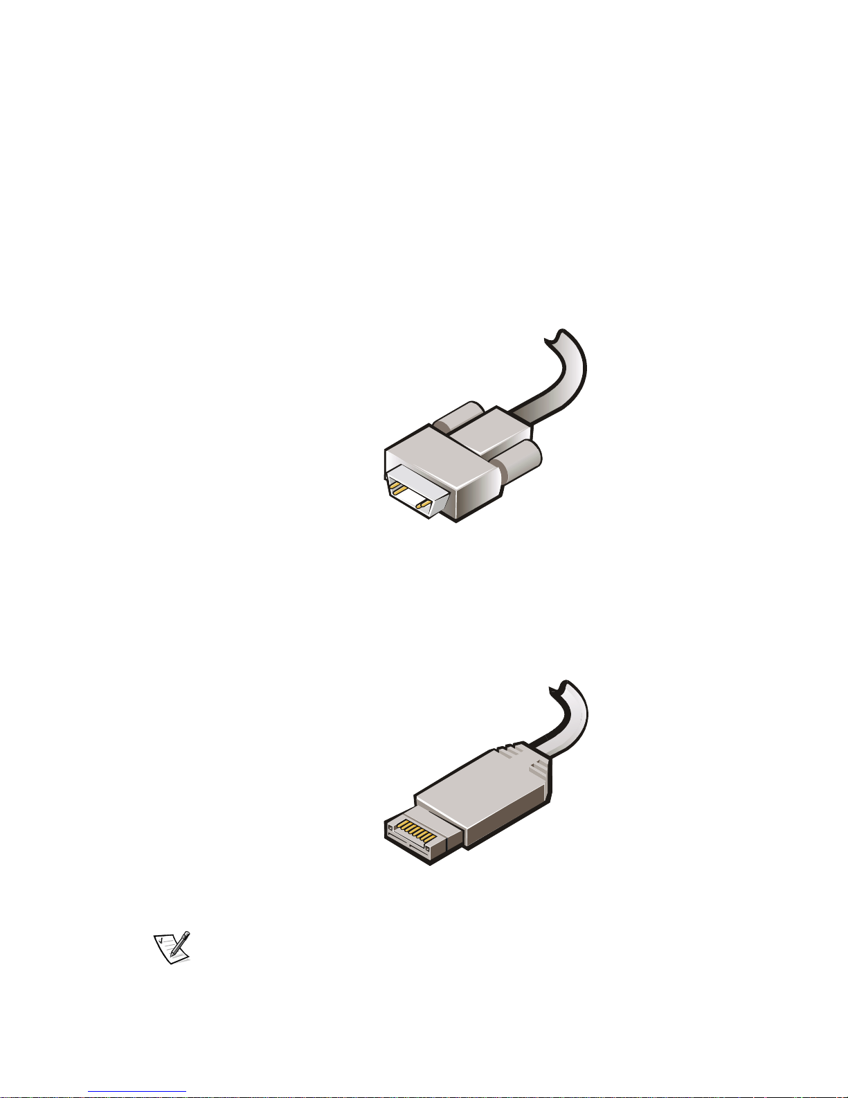
To connect a PowerVault storage system to a PowerEdge system (cluster node), Dell
uses the DB-9 connector and the high-speed serial data connector (HSSDC). The DB9 connector, shown in Figure 4-1, attaches to the PowerVault disk-processor enclosure (DPE) and PowerVault disk-array enclosure (DAE).
Figure 4-1. DB-9 Connector
The HSSDC, shown in Figure 4-2, attaches to the HBA on the PowerEdge systems
and the copper connections to the gigabit interface converters (GBICs) on the PowerVault Fibre Channel switch. The connector is used on the PowerVault DAE and all
Giganet connections.
Figure 4-2. HSSDC Connector
NOTES: Fibre Channel HSSDC cables should not be used to connect Giganet HSSDC
devices because they are not properly shielded for Giganet use.
4-2 User’s Guide
Page 35

Fibre Channel devices using HSSDC connections must not be connected directly to
Giganet devices using HSSDC connections.
Cabling Your Public Network
The NICs in the PowerEdge systems (cluster nodes) provide at least two network
connections for each cluster node—a dedicated private network (cluster interconnect)
between the nodes and a public network connection to the local area network (LAN).
NICs connected to the LAN can also provide redundancy at the communications level
in case the cluster interconnect fails. See your Microsoft Cluster Service (MSCS) documentation for more information on cluster interconnect redundancy.
Using NICs in Your Public Network
Connection to the public LAN is provided by a Broadcom NetExtreme Gigabit Ethernet or Intel PRO/1000 Gigabit Server Adapter installed in each node. The Dell
PowerEdge Cluster FE100/FL100 Datacenter Server supported NICs running Transmission Control Protocol/Internet Protocol (TCP/IP) may be used to connect to the
public network. Additional NICs may be installed to support additional separate public
LAN segments.
Cabling Your Private Network
Your cluster configuration can use Broadcom NetExtreme Gigabit Ethernet NICs or
Giganet cLAN 1000 host bus adapters for the private network (cluster interconnect).
The private network is established by using a network switch and/or Giganet cLAN
switch. You can use standard Ethernet cables to connect these Broadcom
NetExtreme Gigabit Ethernet NICs to a network switch or the GigaNet cable to connect from the Giganet adapter to the cLAN GigaNet switch.
The private network can be used for intracluster communications, intercluster communications, or a separate, dedicated network, which can provide some or, all of the
following features depending on the applications:
• Database replication, snapshots, and synchronization
• High-speed network backup
• Application-to-database communications
• Web server-to-application or web server-to-database communications
Using Broadcom NetExtreme Gigabit Ethernet Controllers
in Your Private Network
The private network is established by using a straight-through Category 5 (CAT 5)
unshielded network cable to connect the Broadcom NetExtreme Gigabit Ethernet
NICs to the private network through a network switch.
support.dell.com Cabling the Cluster Hardware 4-3
Page 36
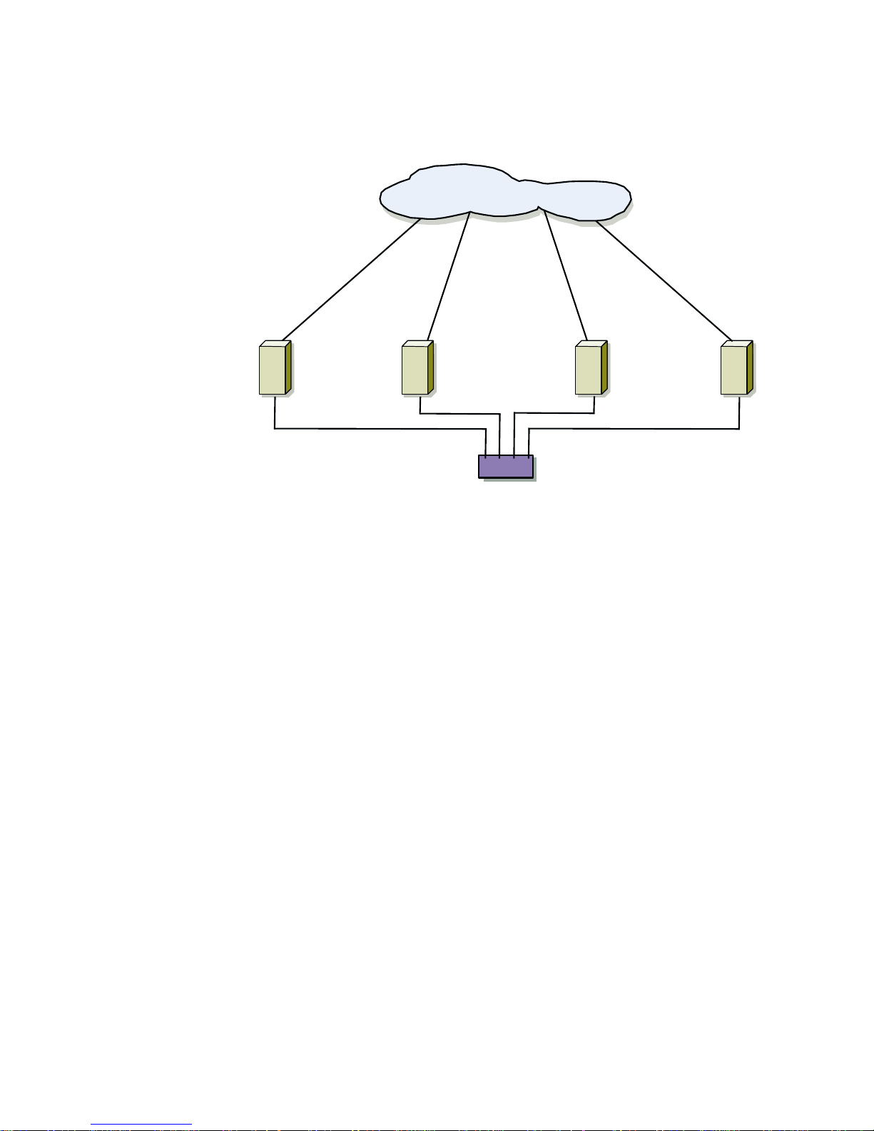
Figure 4-3 shows a cluster configuration that implements Broadcom NetExtreme
Gigabit NICs for the private network.
LAN/WAN
PowerEdge
server
PowerEdge
server
Gigabit network switch
PowerEdge
server
PowerEdge
server
Figure 4-3. Configuration Using a Broadcom NetExtreme Gigabit
NICs for the Private Network
Using Giganet cLAN for the Private Network
PowerEdge Cluster FE100/FL100 Datacenter Server systems can be connected to
each other using the following Giganet high-speed interconnect products:
• GigaNet cLAN host adapters
• Giganet cabling
• Giganet cLAN cluster switches
Giganet cLAN 1000 HBAs provide high band-width, low-latency server-to-server,
server-to- cluster, and cluster-to-cluster interconnections. A faster network connection, however, will not increase the speed of application failover on a cluster or enable
an application to failover to a PowerEdge server (cluster node) outside of the cluster.
Figure 4-4 shows a cluster configuration that implements a GigaNet cLAN NIC for the
private network.
4-4 User’s Guide
Page 37
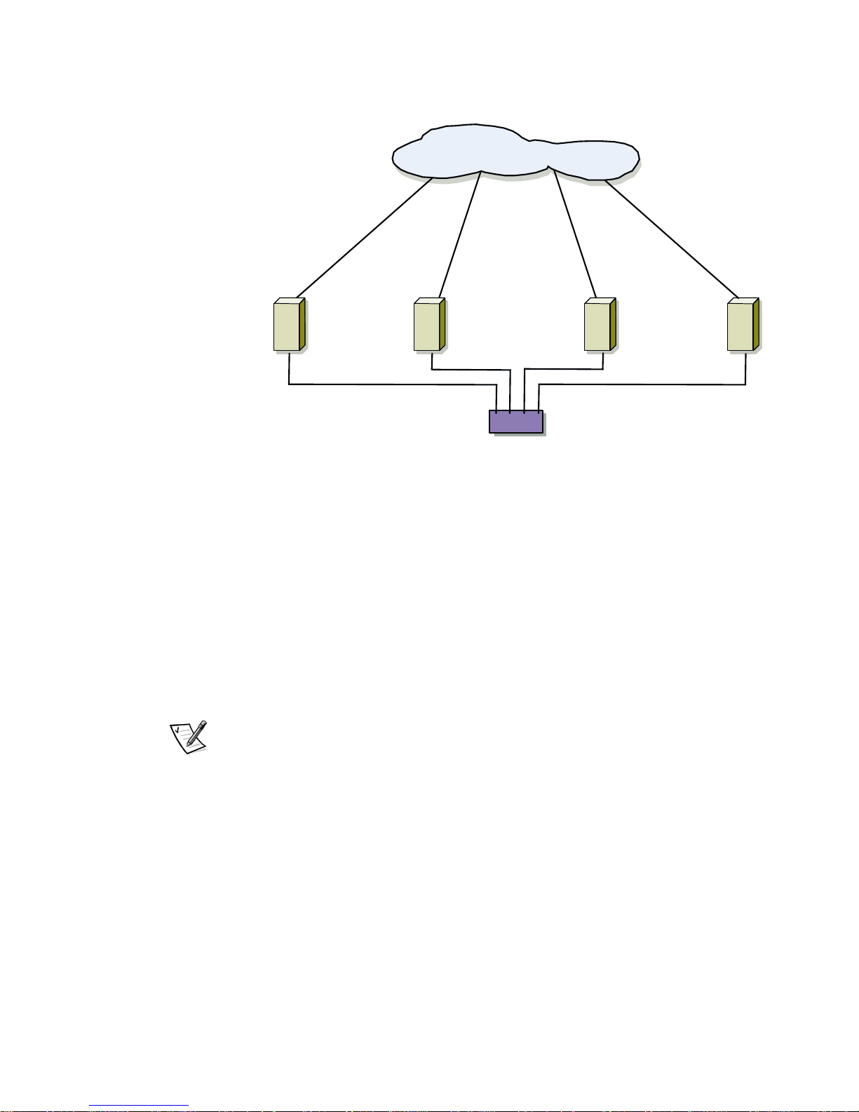
LAN/WAN
PowerEdge
server
PowerEdge
server
GigaNet cLAN
Cluster Switch
PowerEdge
server
PowerEdge
server
Figure 4-4. Configuration Using a GigaNet cLAN NIC for the Private
Network
Protecting Your Cluster From Power Failure
Dell recommends the following guidelines to protect your cluster configuration from
power-related failures:
• Use uninterruptible power supplies (UPS) for each cluster node
• Implement backup generators and power from separate electrical stations
(depending on your situation and environment)
NOTE: See your server and storage system documentation for more information on
the specific power requirements for your cluster system's components.
Connecting Standby Power Supplies in the PowerVault
System
PowerEdge Cluster FE100/FL100 Datacenter Server configurations require dual
standby power supplies (SPS) in the PowerVault storage system. This configuration
provides maximum integrity of the storage processor write-cache. The SPS allows the
write-caching to complete in the event that the primary power supply fails.
Figure 4-5 shows the location and cabling for the SPS units in the PowerVault system.
support.dell.com Cabling the Cluster Hardware 4-5
Page 38
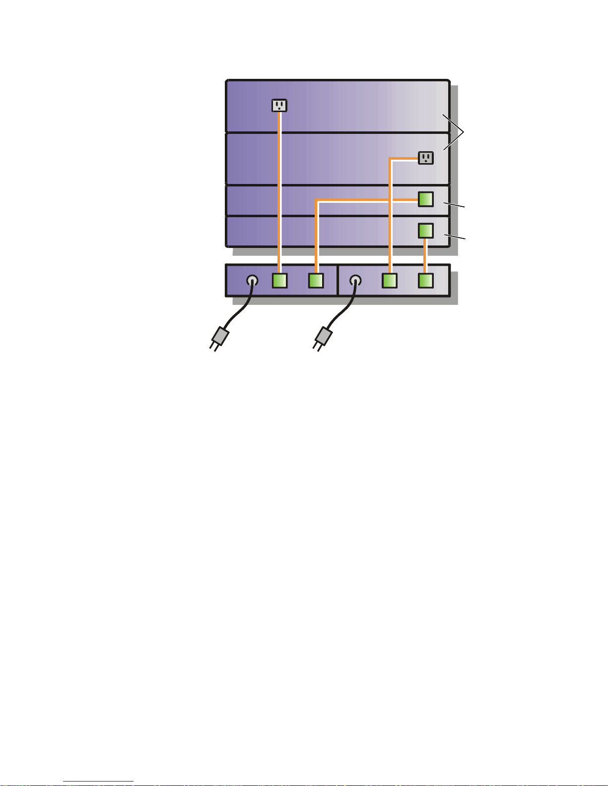
power supplies
PowerVault
65xF storage system
storage
processor-B
storage
processor-A
SPS 2SPS 1
Figure 4-5. Cable Configuration of PowerVault 65xF Power Supplies
See your PowerVault documentation for additional information about the standby
power supplies.
4-6 User’s Guide
Cabling Your Mouse, Keyboard, and
Monitor in a Dell Rack
If you are installing a PowerEdge Cluster FE100/FL100 Datacenter Server configuration in a Dell rack, see the Dell PowerEdge rack installation documentation for
instructions on cabling each cluster node's mouse, keyboard, and monitor to the
mouse/keyboard/monitor switch box in the rack. The switch box enables you to use a
single mouse, keyboard, and monitor for multiple systems.
Page 39

CHAPTER 5
Configuring Storage Systems
(Low-Level Configuration)
This chapter provides the necessary steps for configuring the Dell PowerVault shared
storage hard-disk drives attached to the PowerEdge
Server configuration.
NOTES: Prior to installing the operating system, be sure to make the necessary lowlevel software configurations (if applicable) to your PowerEdge FE100/FL100 Datacenter Server cluster.
Before you configure the cluster software, verify that your system hardware is properly cabled for clustering. See Chapter 4, “Cabling the Cluster Hardware“for
instructions on connecting the components of your PowerEdge FE100/FL100 Datacenter Server cluster.
Cluster FE100/FL100 Datacenter
Configuring PowerVault Shared Storage
Hard-Disk Drives
This section provides some of the necessary procedures for configuring the low-level
connections between the cluster nodes and the storage system.
The PowerVault shared storage system hard-disk drives must be configured before
use. The following subsections provide information on these configurations.
For additional information for configuring low-level connections between the cluster
nodes and the storage systems, see the following chapters:
• Chapter 6, “Configuring the System Software”
• Chapter 7, “Installing Cluster Management and Systems Management Software”
• Chapter 8, “Upgrading Your PowerEdge System to a Cluster Configuration”
• Chapter 9, “Maintaining the Cluster”
• Chapter 10, “SAN Components”
support.dell.com Configuring Storage Systems (Low-Level Configuration) 5-1
Page 40

Configuring the LUNs and RAID Level for the Shared
Storage Subsystem
The storage system hard-disk drives must be bound into logical unit numbers (LUNs)
using the Dell OpenManage Data Supervisor or Dell OpenManage Data
Administrator.
All LUNs, especially the LUN used for the Microsoft Cluster Server (MSCS) quorum
resource, should be bound using a redundant array of independent disks (RAID) level
to ensure high availability. See “Cluster Quorum Resource“in Chapter 6, “Configuring
the System Software” for more information on the quorum resource.
NOTICE: Dell recommends that you use a RAID level other than RAID 0 for
your PowerVault shared storage system. RAID 0 does not provide the level
of availability required for the quorum resource. See the Installation and
Troubleshooting Guide for your PowerVault storage system for more information about setting up RAID levels for the system.
Configuring Internal SCSI Hard-Disk Drives
If you have added new hard-disk drives to your cluster node or you are setting up the
internal drives in a redundant array of independent disks (RAID) configuration, you
must configure the RAID before you can install the operating system. For instructions
on setting up the internal drives, see the appropriate small computer system interface
(SCSI) controller or RAID controller documentation for your system.
RAID Level for the Internal SCSI Hard-Disk Drives
Configure the hard-disk drives using the RAID controller's basic input/output system
(BIOS) configuration utility. For optimum balance of fault tolerance and performance
with a limited number of drives, the recommended configuration for the internal
drives is RAID 1.
NOTE: Most of the RAID hard-disk drives should be in the shared storage system.
For more information on RAID configurations, see the documentation for your specific
PowerEdge RAID controller.
5-2 User’s Guide
Page 41

CHAPTER 6
Configuring the System Software
This chapter describes how to perform the following procedures:
• Preparing for Microsoft Windows 2000 Datacenter Server installation
• Configuring the cluster nodes in a Windows 2000 domain
• Configuring the Windows 2000 Cluster Service
• Configuring the public and private networks
• Installing and configuring your Windows 2000 Datacenter Server network (which
includes information on Dell OpenManage software and using the Windows
2000 Disk Management tool)
• Verifying cluster readiness
• Configuring the Dell OpenManage Managed Node (Data Agent) for a cluster envi-
ronment and cluster failover
• Configuring failover and failback support
Preparing for Microsoft Windows 2000
Datacenter Server Installation
Before installing Microsoft Windows 2000 Datacenter Server on your cluster nodes,
you must perform the following procedures:
• Review the minimum system software and hardware requirements for
implementing Windows 2000 Datacenter Server on a Dell PowerEdge Cluster
FE100/FL100 system
(see Chapter 1, “Getting Started”)
• Review and perform the installation procedures
(see Chapter 2, “Installation Overview”)
• Prepare the PowerEdge and PowerVault systems for clustering
(see Chapter 3, “Preparing PowerEdge and PowerVault Systems for Clustering”)
• Cable the cluster hardware
(see Chapter 4, “Cabling the Cluster Hardware”)
support.dell.com Configuring the System Software 6-1
Page 42

• Configure the storage systems and small computer system interface (SCSI)
drives attached to your Dell PowerEdge Clusters FE100/FL100
Datacenter Server system
(see Chapter 5, “Configuring Storage Systems (Low-Level Configuration))”
NOTICE: When you install Datacenter Server, do not enable the standby
mode or hibernation mode incorporated in Windows 2000 Datacenter
Server. These modes are not supported in cluster configurations.
When you install Datacenter Server, you must configure the operating system to
enable clustering. These configuration requirements are described in the Microsoft
Windows 2000 Datacenter Server documentation. The following sections briefly discuss these configurations.
Configuring the Cluster Nodes in a
Windows 2000 Domain
Windows 2000 operates on a domain model in a server-based network. In a
Windows 2000 cluster, all of the cluster nodes must belong to a common domain—a
logical grouping of servers (such as cluster nodes) that share a common database and
security policy.
In a Windows 2000 cluster domain, all cluster nodes are assigned one of the following tasks:
• Domain controllers—A cluster node that contains the master copy or a copy of
the domain security policy and domain database, and authenticates user logon to
the network. Multiple domain controllers provide redundancy for the network if
one of the domain controllers goes offline.
• Member servers—A cluster node that is not a domain controller and usually
provides user resources as a file, application, database, or remote access server
(RAS).
The Dell PowerEdge Cluster FE100/FL100 Datacenter Server configuration supports
the following domain assignments for each cluster node:
• All cluster nodes are member servers in a Windows 2000 domain.
• All cluster nodes are member servers in a Windows 2000 Active Directory
domain.
• All cluster nodes are domain controllers in a Windows 2000 Active Directory
domain.
• One cluster node is a domain controller in a Windows 2000 Active Directory
domain and the other cluster node is a member server in that domain.
If a cluster node is not a domain controller and is unable to contact a domain controller, the cluster node will not be able to authenticate client requests. If a cluster node
is a domain controller, client access to the cluster node’s cluster resources may be
discontinued if the cluster node cannot contact the remaining domain controller(s).
6-2 User’s Guide
Page 43

NOTE: Domain controller functions may cause additional logon, authentication, and
replication traffic and overhead on the node.
Configuring the Windows 2000 Cluster
Service
To configure the Windows 2000 Cluster Service during the Windows 2000
Datacenter Server installation, perform the following steps:
1. Ensure that you have performed the tasks in the section, “Preparing for
Microsoft Windows 2000 Datacenter Server Installation,” found earlier in this
chapter.
2. Click the Start button, and point to Settings—> Control Panel.
3. Click Add/Remove Programs.
4. Click Add/Remove Windows Components.
5. Click Configure next to Configure Cluster Service.
The Cluster Service Configuration Wizard appears.
Follow the steps in the wizard to complete the installation.
When you configure the Cluster Service, you are prompted to assign a function
for the public and private networks. To provide added fault tolerance for the private network, Dell recommends that you configure the private network by
performing the following steps:
a. Set the private network to Use for internal communications only.
NOTE: Dell suggests that you rename your private network to avoid confusion.
b. Set the public network to All communications.
This setting provides a redundant path for the cluster-to-cluster communication in the event the private network fails.
c. Set each subsequent NIC to Public communications only.
d. Assign the private network with the highest priority for internal
communications.
If you did not check the box for Cluster Service during the Windows 2000
Datacenter Server installation, perform the following steps:
1. Ensure that you have performed the tasks in the section, “Preparing for
Microsoft Windows 2000 Datacenter Server Installation,” found earlier in this
chapter.
support.dell.com Configuring the System Software 6-3
Page 44

2. Insert the CD labeled Windows 2000 Datacenter Server CD-ROM into the CDROM drive.
3. Click the Start button, and select Settings—> Control Panel.
4. Click on Add/Remove Programs.
5. Click Add/Remove Windows Components.
6. Select Cluster Service in the Windows Components Wizard.
7. C l i c k Next to copy the Cluster Service files to the system hard-disk drive.
When the files are copied to the system, the Cluster Service Configuration
Wizard appears.
8. Follow the steps in the wizard to complete the installation.
When you configure the Cluster Service, you are prompted to assign a function
for the public and private networks. To provide added fault tolerance for the private network, Dell recommends that you configure the private network by
performing the following steps:
a. Set the private network to Use for internal communications only.
NOTE: Dell suggests that you rename your private network to avoid confusion.
b. Set the public network to All communications.
This setting provides a redundant path for the cluster-to-cluster communication in the event the private network fails.
c. Set each subsequent NIC to Public communications only.
d. Assign the private network with the highest priority for internal
communications.
Configuring the Public and Private
Networks
Configuring the public and private networks correctly in each node is critical to installing the Cluster Service. The following subsections provide the principles and
procedures necessary to configuring your network.
Static IP Address
A static Internet Protocol (IP) address is an Internet address that a network administrator assigns exclusively to a system or a resource. The address assignment remains
in effect until the network administrator changes the address.
The Cluster Service requires a static IP address for the name of each cluster node in
order to manage the cluster. Because each node in a cluster has at least two NICs for
6-4 User’s Guide
Page 45

both the public and private networks, the minimum number of static IP addresses
required for a four-node clustering is nine—two for each NIC in the cluster nodes and
one for the cluster.
Cluster-aware applications running on the cluster may require additional IP addresses.
For example, Microsoft SQL Server requires at least one static IP address for the virtual server (Microsoft SQL Server does not use the cluster's IP address). Also, each
cluster node containing Internet Information Server (IIS) that is configured for failover
requires a unique static IP address.
Configuring the IP Addresses for the Private Network
A PowerEdge Cluster FE100/FL100 Datacenter Server configuration requires at least
two NICs in each PowerEdge server (cluster node), with each NIC dedicated to one of
the following networks:
• Public network (local area network [LAN])
• Private network (node-to-node communications through the cluster interconnect)
Attaching two networks to the cluster enables fault tolerance for cluster communications. If the cluster interconnects fails, the cluster can still use the public network for
cluster communications.
The NICs installed in a cluster node must reside on different IP subnets with the
cluster interconnect assigned to a separate IP subnet or a different network ID than
the LAN subnet(s) used for a client connection.
Dell recommends using the static IP address assignments in Table 6-1 for the NICs
assigned to the private network.
Table 6-1. IP Addresses for the Private Network
Cluster Node IP Address Subnet Mask
Node 1 10.0.0.1 255.255.255.0
Node 2 10.0.0.2 255.255.255.0
Node 3 10.0.0.3 255.255.255.0
Node 4 10.0.0.4 255.255.255.0
NOTE: The IP address assignments for the public LAN segments may vary according
to your network environment.
If multiple private network NICs are connected to a network switch, make sure that all
of the NICs connected to the private network have a unique IP address. For NICs connected to the private network in any other cluster connected to the same switch, you
can continue the IP address assignment displayed in Table 6-1 by using 10.0.0.5 and
10.0.0.6, and continuing the address assignment scheme for any additional NICs connected to a private network NIC in the same cluster.
The IP address assignments for the public network may vary according to your network environment. If the IP assignments are set up correctly, all of the NIC resources
support.dell.com Configuring the System Software 6-5
Page 46

will respond to ping commands and will appear online after installing Cluster Service
(MSCS) on the cluster nodes. If the IP address resources are not set up correctly, the
cluster nodes may not be able to communicate with the domain and the Windows
2000 Cluster Configuration wizard may not allow you to configure all of your
networks.
Installing and Configuring Your Windows
2000 Datacenter Server Network
The following sections describe an example for using Windows 2000 for configuring
your PowerEdge Cluster FE100/FL100 Datacenter Server network.
NOTE: The IP addresses for the public network, default gateway, domain name system (DNS) servers, and Windows Internet naming service (WINS) servers used here
are examples and are not representative of actual addresses that should be used for
your environment.
Overview of a Windows 2000 Datacenter Server Network
Installation
The Windows Networking Components wizard detects each individual adapter
installed in your system and allows you to configure them separately. If your adapter
is not detected by Windows 2000, you will need to manually add its Windows 2000
digitally-signed driver. If there are two or more identical NICs installed in the cluster
node, it may be difficult to determine which NIC you are trying to configure.
There are several factors that can determine how Windows 2000 scans the peripheral
component interconnect (PCI) buses. If you cannot communicate with the domain or
cannot ping other adapters on the same subnet after you have completed the following steps, you must reconfigure Transmission control protocol/Internet protocol
(TCP/IP).
Table 6-2 provides the configuration information that is used in the following
procedure.
Table 6-2. IP Addresses
Use Cluster Node 1 Cluster Node 2 Cluster Node 3 Cluster Node 4
Public network static
IP addresses permits
communication with
clients and domain
controllers
Public network subnet mask
Public network
default gateway
192.168.1.101 192.168.1.102 192.168.1.103 192.168.1.104
255.255.255.0 255.255.255.0 255.255.255.0 255.255.255.0
192.168.1.1 192.168.1.1 192.168.1.1 192.168.1.1
6-6 User’s Guide
Page 47
Table 6-2. IP Addresses (continued)
Use Cluster Node 1 Cluster Node 2 Cluster Node 3 Cluster Node 4
Private network static
10.0.0.1 10.0.0.2 10.0.0.3 10.0.0.4
IP address cluster
interconnect
Private network sub-
255.255.255.0 255.255.255.0 255.255.255.0 255.255.255.0
net mask
DNS servers Primary
192.168.1.11
Secondary
192.168.1.12
The following procedure provides an example of a Windows 2000 Datacenter Server
networking installation using the IP addresses in Table 6-2:
1. When prompted for Default or Custom network configuration during the
Windows 2000 Datacenter Server installation, choose Custom.
NOTE: If you select the Default network configuration, the system automatically
configures all installed networks for Dynamic Host Configuration Protocol
(DHCP).
2. For the first adapter detected by Windows 2000, select Internet Protocol (TCP/
IP) and click Properties to configure TCP/IP properties.
Primary
192.168.1.11
Secondary
192.168.1.12
Primary
192.168.1.11
Secondary
192.168.1.12
Primary
192.168.1.11
Secondary
192.168.1.12
NOTE: For the purposes of this example, the first adapter detected is the public
network NIC.
3. Under the General tab, select Use the following IP address to configure a
static IP address.
4. Enter the static IP address for the public network NIC.
For example, in Table 6-2, the static IP address for cluster node 1 is 192.168.1.101.
NOTE: Ensure that each cluster node has a unique IP addresses on the same
subnet for the public network.
5. Enter the subnet mask for the NIC.
For example, in Table 6-2, the subnet mask for Cluster Node 1 is 255.255.255.0.
6. Enter the default gateway's IP address.
For example, in Table 6-2, the subnet mask for Cluster Node 1 is 192.168.1.1.
7. Enter the IP addresses for the primary and secondary DNS servers.
For example, in Table 6-2, the IP addresses for the primary and secondary DNS
servers are 192.168.1.21 and 192.168.1.22, respectively.
support.dell.com Configuring the System Software 6-7
Page 48

8. If you are configuring WINS servers, click Advanced and choose the WINS tab to
enter the IP addresses for the WINS servers.
For example, in Table 6-2, the IP addresses for the WINS servers in Cluster Node
1 are 192.168.1.11 and 192.168.1.12.
NOTE: Some Windows environments may not use WINS servers.
9. Click OK to return to the Windows Networking Components wizard and repeat
steps 2 through 8 to configure the next adapter.
This adapter is used for the private connection (node-to-node cluster
interconnect).
10. Highlight Internet Protocol (TCP/IP) and select Properties to specify TCP/IP
properties for the private connection.
11. In the General tab, select Use the following IP address to configure a static IP
address.
12. Enter the IP address and subnet mask for this NIC.
For example, in Table 6-2, the IP address and subnet mask for Cluster Node 1 are
10.0.0.1 and 255.255.255.0, respectively. The WINS and DNS configurations are
not required for the NIC attached to the private network.
13. After completing the network configurations for the NICs installed in the cluster
®
nodes, select the option to join a Windows NT
or Windows 2000 domain. When
prompted, enter a user account with account operator or administrator privileges
on the domain.
NOTE: If you receive an error message indicating that the domain cannot be
found, verify that a network link is present using the light emitting diode (LED)
indicators on the NICs (if available) and that the TCP/IP configuration is correct,
including the default gateway, DNS server(s), and WINS server(s).
If problems persist, ensure that each NIC is configured for the correct network. If
this problem occurs, switch the NIC cables (if both NICs are identical) or reconfigure the TCP/IP addresses for each NIC.
14. Repeat steps 1-13 for other cluster nodes using unique static IP addresses for
each networking segment. Be sure to use the same network subnet for each network segment used on Cluster Node 1.
Updating the Host Bus Adapter Driver
Windows 2000 Datacenter Server automatically detects and installs a driver for some
host bus adapters (HBA). Before you configure the shared storage system, you must
update this driver with the latest driver version.
See “PowerEdge Cluster FE100/FL100 Datacenter Server Support Configuration
Requirements“in Chapter 1, “Getting Started,” for information on the correct driver
version for your HBA.
6-8 User’s Guide
Page 49

See the readme.txt file on the HBA driver diskette for more information on installing
and updating the driver.
Installing the Dell OpenManage Storage Management
Software for the PowerVault Storage System
To manage and configure the storage system attached to the Dell PowerEdge Cluster
FE100/FL100, you must install Dell OpenManage software to manage the storage
systems attached to the cluster nodes. Table 6-3 provides a list of the Dell
OpenManage management software required for the Dell PowerEdge Cluster FE100/
FL100 Datacenter configuration where you should install the software.
NOTE: You must install the Dell OpenManage Storage Management software before
continuing with the following sections.
Table 6-3. Dell OpenManage Storage Management
Software
Dell OpenManage Product Location of Software
Dell OpenManage
Application Transparent Failover (ATF)
Dell OpenManage
Managed Node (Data Agent)
Dell OpenManage Data Supervisor
or
Dell OpenManage Data Administrator
Table 6-4 provides a description of the Dell OpenManage software for the
Dell PowerEdge Cluster FE100/FL100 configuration.
All cluster nodes
All cluster nodes
One or all cluster nodes
Table 6-4. Dell OpenManage Software
Dell OpenManage
Product
Dell OpenManage
Application Transparent
Failover (ATF)
Reestablishes a failed connection to a
PowerVault 65xF caused by a communication failure, such as a failed storage processor, HBA, or Fibre Channel cable.
Without human intervention, ATF can
reroute the input/output (I/O) through a
secondary path to the PowerVault 65xF to
provide connectivity for running applications.
Description Cluster
Nodes
All cluster
nodes
support.dell.com Configuring the System Software 6-9
Page 50

Table 6-4. Dell OpenManage Software (continued)
Dell OpenManage
Product
Dell OpenManage
Managed Node
(Data Agent)
Dell OpenManage
Data Supervisor
(Optional)
Dell OpenManage
Data Administrator
(Optional)
Description Cluster
Provides connectivity from the cluster
node (host) to the PowerVault storage system, thereby allowing Data Supervisor and
Data Administrator to send and receive
information to and from the PowerVault
65xF connected to a Windows 2000 Datacenter Server host (cluster node).
Data Agent must be installed on one of
the cluster nodes with either Data
Supervisor or Data Administrator.
Provides PowerVault storage management
and configuration through a graphical user
interface (GUI). Data Supervisor allows
you to configure and manage the disks
and components in a single PowerVault
65xF, as well as bind and unbind logical
unit numbers (LUNs), change configuration settings, and create LUNs.
Provides PowerVault storage management
and configuration through a GUI. Data
Administrator contains the same capabilities as Data Supervisor, but also allows
you to configure and manage multiple
PowerVault storage components in a single window.
Nodes
All
cluster
nodes
One or all
cluster
nodes
One or all
cluster
nodes
6-10 User’s Guide
After you install the Dell OpenManage management software, you must bind the
LUNs in the shared storage system that is attached to the cluster. In some cases, the
LUNs may have been preconfigured by Dell. However, you must install the management software and verify that your LUN configuration exists.
LUN management, configuration, and remote administration is achieved from the
cluster node by starting the Dell OpenManage Managed Node service and using
either Data Supervisor or Data Administrator. At least one LUN (RAID drive) is
required for an active node.
For example, if you have four active cluster nodes and no passive nodes (which is an
4
active
configuration) you will need to create a minimum of four LUNs. If your cluster
configuration consists of three active cluster nodes and one passive cluster node
3
(which is an active
For more information on active
n
“A c t i v e
/Active and Activen/Passive Configurations” in Chapter 1, “Getting Started.”
configuration), you will need to create a minimum of three LUNs.
n
/active and activen/passive configurations, see
Dell recommends creating at least one LUN—the smallest unit of failover—for each
application. If multiple partitions are created on a single LUN, these partitions will not
be able to failover individually from node-to-node.
Page 51

For more information on installing Dell OpenManage ATF, Dell OpenManage Managed
Node Agent, Dell OpenManage Data Supervisor, or Dell OpenManage Data Administrator, see the PowerVault documentation that came with the storage system.
Configuring Shared Drives Using the Windows 2000 Disk
Management Tool
For disk configuration, Windows 2000 uses a disk management tool called Computer
Management located at Administrative Tools—> Computer Management.
The following subsection explains how to use Computer Management to assign drive
letters and format hard-disk drives on the shared storage system.
Assigning Drive Letters and Formatting Drives on the Shared Storage
System
Windows 2000 Cluster Service recognizes the logical drives of the shared storage
system only if the drives are partitioned, formatted using Windows NT File System
(NTFS), assigned drive letters, and configured as basic disks (as opposed to dynamic
disks). Also, the assigned drive letters for each shared storage partition must be identical on both nodes.
To assign drive letters and format shared hard-disk drives, perform the following
steps:
1. C l i ck t h e Start button, select Programs, select Administrative Tools, and click
Computer Management.
2. Select the Disk Management folder to display Windows drive configuration settings. If you are using the Disk Management tool for the first time, the Write
Signature and Upgrade Disk wizard appears.
A list of all shared drives is displayed in the Disk to Write Signature window.
NOTE: If the Upgrade Disk wizard does not appear and the unformatted drives
are not visible, verify that the updated HBA driver is installed and that the Cluster
Service is not installed and running on another cluster node. If the Cluster
Service is running on another cluster node, you cannot configure the shared
storage disks.
3. Click the check box for each disk, and then click Next.
4. In the Select disks to be upgraded window, deselect all checked boxes.
5. Click Next.
The disk configuration information appears.
NOTICE: The upgrade procedure creates dynamic disks or volumes
from the selected disks that can not be used by Cluster Service. Before
you proceed to the following step, ensure that the disks are not being
upgraded by deselecting each disk.
support.dell.com Configuring the System Software 6-11
Page 52

The right column shows the shared drives as raw, unformatted drives, with unallocated disk capacity. The left column shows Basic disks.
If the left column shows Dynamic disks, right-click that box and select Revert to
Basic for each disk in the shared storage system.
NOTICE: Reverting disks to Basic destroys all data on the drive.
6. For each shared disk, run the Create Partition wizard by performing the following
steps:
e. In the row for the first shared disk, right-click over the right-column box.
f. Select Create Partition, and then click Next.
g. Select Primary partition, and then click Next.
h. In the next dialog box, Dell recommends choosing all available disk space.
NOTE: For additional information on partition size recommendations, see
“Cluster Quorum Resource,” found later in this chapter.
If you create multiple partitions on a single disk, the partitions will not be able to
individually move between the cluster nodes. All partitions on a given disk move
together. Therefore, Dell recommends that you run separate applications on separate disks, rather than using separate partitions on the same disk.
You may want to create a separate partition on one of your shared storage disks
for the quorum resource log files. For more information, see “Installing and Configuring the Windows 2000 Cluster Service,“found later in this chapter.
i. In the next window, select the drive letter and the disk format parameters.
NOTE: All shared storage drives must be formatted with NTFS.
j. Review the selections in the windows and click Finish.
After formatting is complete, the right column for each drive shows a health
status of Healthy.
Using the Windows 2000 Dynamic Disks and Volumes
Windows 2000 does not support the use of dynamic disks (upgraded disks) or volumes for shared storage disk drives. If shared storage disk drives are configured as
dynamic disks, the Cluster Configuration wizard will not be able to discover and
access the disks. If your shared storage disk drives are already configured as
dynamic, see the previous section, “Assigning Drive Letters and Formatting Drives
on the Shared Storage System” for the procedure on changing dynamic disks to basic
disks.
6-12 User’s Guide
Page 53

Verifying Cluster Readiness
Before you install Cluster Service in the PowerEdge cluster nodes and the PowerVault
storage systems, check the system and verify that the cluster meets the following
conditions:
• All cluster nodes are able to log in to the domain.
• The shared drives are partitioned, formatted, and named on each node.
• All IP addresses and network names for each NIC and each cluster node can
communicate with each other.
For example, open a command prompt and use the ping command to verify clus-
ter node communications.
Installing and Configuring the Windows 2000 Cluster
Service
When you install Windows 2000 Datacenter Server and install the Cluster Service,
the Cluster Service configuration files are copied to the system. Before you configure
a PowerEdge server as a cluster node, Cluster Service must be configured using the
Cluster Configuration wizard.
See Microsoft's online help for configuring the Cluster Service located at
http://www.microsoft.com.
The following subsections explain some of the necessary procedures for installing
and configuring Windows 2000 Datacenter Cluster Service.
Cluster Quorum Resource
A quorum resource is typically a hard-disk drive in the shared storage system that
serves the following purposes in a Cluster configuration:
• Provides Windows 2000 with a list of active nodes that can communicate with
each other so the operating system can form a working cluster
• Acts as an arbiter between the cluster nodes to ensure that the specific data
necessary for system recovery is maintained consistently across the nodes
• Logs the recovery data sent by the cluster node
Only one cluster node can control the quorum resource at a time, and this cluster
node remains running when it cannot communicate with the remaining nodes in the
cluster. If the cluster node containing the quorum resource is unable to communicate
with another cluster node, the Cluster Service automatically shuts down the node
that does not control the quorum resource.
If one of the cluster nodes fails, any changes to the cluster configuration database are
logged to the quorum disk. This logging process occurs to ensure that the node that
gains control of the quorum disk can access an up-to-date version of the cluster configuration database.
support.dell.com Configuring the System Software 6-13
Page 54

Cluster Resource Group
When you create a new cluster, the cluster will contain (by default) a cluster group
that contain the default settings and resources for the cluster. This group contains a
list of the cluster resources, which includes the following:
• Cluster IP address
• IP network name (cluster network resource name)
• Quorum disk
When you install the Cluster Service and configure the cluster in the Cluster
Configuration wizard, the IP address and the name of the cluster you enter in the
wizard becomes the IP address and IP network name of the cluster. If you prefer to
relocate the quorum disk, you can move the quorum disk to another disk group.
Adding Additional Applications and Data to the Quorum Disk
The quorum disk, by default, is installed in the “Cluster Group.” Dell recommends
that you do not install additional applications into the Cluster Group. The Cluster
Group also contains a network name and IP address resource, which is used to manage the cluster. However, if you choose to use the quorum disk for applications and
data, Dell recommends that you perform the following steps:
1. Create a small partition on one of the shared RAID drives.
2. Allocate 100 megabytes (MB) to the partition.
One hundred megabytes (MB) (100 MB) is a satisfactory size for this partition,
but no other applications or data should be stored there.
3. Assign a drive letter to the partition.
4. Assign the Cluster Service files (quorum disk) to this drive letter during installa-
tion.
This procedure will prevent other application programs or data from filling the partition where the quorum resource is located.
NOTICE: If the quorum disk's partition becomes full, the quorum
resource is not able to expand and may become corrupt. If a separate
partition is not used for the quorum resource, ensure that the quorum
disk’s partition does not become full when used by other applications
or files.
You can place applications and data on the remaining partitions or space on the
shared disk with the quorum resource partition. These partition(s) must be placed
in the same cluster group as the quorum resource partition to ensure failover
consistency.
5. Move the quorum disk (which the quorum resource partition) out of the cluster
group and into another group.
6-14 User’s Guide
Page 55

The status of any applications and data using the quorum disk will not affect the
status of the Cluster Group.
NOTE: For information on moving the quorum files, see Microsoft's online help.
Because the quorum disk plays a crucial role in cluster operation, losing the quorum
disk will cause the entire cluster to fail. To prevent this type of failure, configure the
quorum resource on a shared disk drive protected by a fault tolerant redundant array
of independent disks (RAID) set, preferably on a volume that spans multiple storage
enclosures.
Verifying Cluster Functionality
To ensure that a PowerEdge FE100/FL100 Datacenter Server Cluster configuration
functions properly, check the system's functionality and configuration settings and
verify that the cluster meets the following conditions:
• All IP addresses and network names in the cluster are communicating with each
other and other components in the network.
• The Cluster Service is running.
• All resources and recovery groups are online.
• All resources and recovery groups come online on the remaining cluster node(s)
after manually moving them.
Verifying Cluster Service
The Cluster Service manages all of the activity on the cluster node, including membership management, communication management, and failover management. When
Cluster Service is properly installed, it starts on each cluster node and responds automatically in the event that one of the nodes fails or goes offline.
To verify that Cluster Service is running on the cluster node, perform the following
steps:
1. C l i ck t h e Start button and select Programs—> Administrative Tools—>
Services.
The Services window appears.
2. Confirm that Cluster Service is started and that it is set to start automatically.
Verifying Cluster Resource Availability
In the context of clustering, a resource is a basic unit of failover management. Application programs are made up of resources that are grouped together for recovery
purposes. All recovery groups—and therefore the resources that comprise the recovery groups—must be online (or in a ready state) for the cluster to function properly.
support.dell.com Configuring the System Software 6-15
Page 56

To verify that the cluster resources are online, perform the following steps on the
monitoring cluster node:
1. Click the Start button and select Programs—> Administrative Tools—> Cluster
Administrator.
2. Open a connection to the cluster and check the running state of each recovery
group. If a group has failed, one or more of its resources may be offline.
Troubleshooting the failed resources is beyond the scope of this document, but examining the properties of each resource and ensuring that the specified parameters are
correct are the first two steps in this process. In general, if a resource is offline, it can
be brought online by selecting it, right-clicking it, and selecting Bring Online from the
pulldown menu. For information about troubleshooting resource failures, see the
Microsoft Cluster Service help files.
Configuring the Dell OpenManage
Manage Node (Data Agent) for a Cluster
Environment
The following procedure provides the necessary steps to configure your Dell
OpenManage Managed Node (Data Agent) for clustering.
To configure the Dell OpenManage Managed Node (Data Agent) in a cluster, perform
the following steps:
1. O p e n t h e Agent Configurator.
2. In the Host Description field, type the description of the server.
3. In the Contact Person field, type the name of the contact person (optional).
4. Click the Enable Cluster Support check box to enable the new cluster support
functionality.
5. In the Devices pulldown menu, click Auto-Detect.
This selection forces the Agent Configurator to discover the RAID configuration
of the storage subsystem.
6. In the Privileged Users field, type the name(s) of the privileged user(s).
7. In the File pulldown menu, click Save to save the new configuration.
Configuring the Data Agent for Cluster
Failover
The Dell OpenManage Managed Node (Data Agent) should be installed as a cluster
resource and managed by the Cluster Service so only one Data Agent is running at
6-16 User’s Guide
Page 57

any one time. Only one Data Agent should be running to ensure that the nodes have a
consistent view of the PowerVault storage system.
To install the Data Agent as a cluster resource, perform the following steps:
1. Confirm that Dell OpenManage Managed Node (Data Agent) is installed on all of
the cluster nodes and is configured to start manually.
2. Open the Cluster Administrator.
3. Right-click Cluster Group, point to New, and click Resource.
4. In the Name field, type Manage Node Agent.
5. In the Resource Type menu, select Generic Service.
6. Click Next.
7. In the Possible Owners window, verify that all of the cluster nodes appear in the
window.
8. Click Next.
9. Highlight Cluster IP Address and Cluster Name, move them to the Resource
Dependencies window, and then click Next.
Enabling these dependencies ensures that as soon as the Data Agent starts, the
Administrator can connect to the Data Agent through the cluster IP address or
the cluster name.
10. In the Service Name field, type Dell_OpenManage_Data_Agent and then
click Next.
11. C li ck Finish.
12. Click OK.
13. Right-click the new resource and select Properties.
The Properties window appears.
14. Deselect Affect group and click OK.
15. Right-click Cluster Group and select Bring Online.
If the resource is online, a message window appears stating “Dell OpenMan-
age Data Agent has started.”
NOTE: When the Dell OpenManage Managed Node Agent is installed as a
generic resource in the cluster, the cluster software is responsible for managing
the Data Agent. If you try to stop the Data Agent in the Control Panel or in the
Agent Configurator, the cluster will try to start the Data Agent automatically. If
this event happens, stop or start the Data Agent by using Cluster Administrator
to bring the Managed Node Agent resource offline or online.
support.dell.com Configuring the System Software 6-17
Page 58

Configuring Failover and Failback Support
When an individual application or user resource (also known as a cluster resource)
fails on a cluster node, Cluster Service will detect the application failure and try to
restart the application on the cluster node. If the restart attempt reaches a preset
threshold, Cluster Service brings the running application offline, moves the application
and its resources to another cluster node, and restarts the application on the other
cluster node(s). This process of automatically moving resources from a failed cluster
node to other healthy cluster node(s) is called failover.
When the system administrator repairs and restarts the failed cluster node, the opposite process occurs. After the original cluster node has been restarted and rejoins the
cluster, the Cluster Service will bring the running application and its resources offline,
move them from the failover cluster node to the original cluster node, and then restart
the application. This process of returning the resources back to their original cluster
node is called failback.
You can configure failback to occur at any given time, or not at all. However, be sure to
configure the failback time during your offpeak hours to minimize the effect on users,
as they may see a delay in service until the resources come back online.
In order to failover and failback running applications, cluster resources are placed
together in a group so the Cluster Service can move the cluster resources as a combined unit. For example, an application such as Internet Information Server (IIS)
requires a virtual disk, IP address, and a network name resource. IIS also requires a
resource called “IIS Server Instance.” The IIS services and the IIS Server Instance
resource can be placed in its own group and labeled, “IIS Group” for identification.
Since the IIS Group (the resource group) contains all of the resources for the application (IIS), Cluster Service can bring all of the necessary components online in their
proper order to ensure that failover and/or failback procedures transfers all of the user
resources as transparently as possible.
6-18 User’s Guide
The following section provides information on failover support for 4-node clustering,
and provides tables for each failover option that includes a preferred cluster node list
for cluster group failover or failback that will help you implement your failover
configuration.
Failover Support Through Four-Node Clustering
One of the key features of Datacenter Server is that it supports a 2-node, 3-node, and
4-node failover clustering solution. The PowerEdge FE100/FL100 Datacenter Server
systems provide the 2-node to 4-node failover cluster solution and is designed to provide higher levels of availability through improved service offering and additional
cluster functionality.
When a failover situation occurs, the Cluster Service will take the resources offline
and (by default) move them to the next cluster node number. For example, if cluster
node 1 fails, Cluster Service will move the resources to the next cluster node number,
which is cluster node 2. This default type of failover is called “Cascading failover.”
After the malfunctioning cluster node is repaired and failback is enabled, Cluster Service will failback the resources using the same procedures as failover.
Page 59

You can also change the failover order for your resources by modifying the Preferred
Owners list in the Modify Preferred Owners window, which is accessed through
Cluster Administrator. If some of your cluster nodes lack the resources to handle the
additional workload of a failover application, rather than using the “Cascading failover”
order (node 1—> node, 2—> node 3—> node 4), you can change the failover configuration to a preselected order of cluster nodes.
For example, if you know that node 2 and node 3 have ample resources to handle one
application and nodes 1 and 4 are borderline, you can configure that application with
this failover order: node 2—> node 3—> node 1—> node 4.
Modifying the Failover Sequence of the Disk Groups
To modify the failover sequence of the disk groups, perform the following steps:
1. Click the Start button and select Programs—> Administrative Tools—> Cluster
Administrator.
2. Locate the disk group that contains the resources you want to failover in a preferred failover order.
3. Right-click the disk group and select Properties.
The Properties window appears.
4. In the General tab, click Modify.
The Modify Preferred Owners window appears with a list of available cluster
nodes in the left pane and a list of preferred owners in the right pane. The cluster
nodes in the Preferred Owners pane are listed in order of failover attempt.
5. Reorder the disks groups by selecting a disk group and clicking the Up and Down
arrows on the right side of the window.
6. Click OK.
The Properties window appears.
7. C l i c k OK.
support.dell.com Configuring the System Software 6-19
Page 60

6-20 User’s Guide
Page 61

CHAPTER 7
Installing Cluster Management
and Systems Management
Software
This chapter provides information on configuring and administering your cluster using
the following cluster management software:
• Microsoft Windows 2000 Cluster Administrator
• Dell OpenManage Cluster Assistant With ClusterX
Microsoft Cluster Administrator
Cluster Administrator is a built-in tool in Windows 2000 Datacenter Server for configuring and administering a cluster. The following procedures describe how to run
Cluster Administrator locally on a cluster node and how to install Cluster Administrator on a remote console.
Running Cluster Administrator on a Cluster Node
To launch the Cluster Administrator from the Start menu, click the Start button and
select Programs—> Administrative Tools—> Cluster Administrator. The Cluster
Administrator window appears.
Installing Cluster Administrator on a Remote Console
Running Windows 2000 Professional
You can administer and monitor the Cluster Service remotely by installing the
Windows 2000 Administrative Tools on a Windows 2000 client. Cluster Administrator
is part of the Administrator Pack, included with Windows 2000 Server editions.
To install the cluster administrator on a remote console running Windows 2000 Professional, perform the following steps:
1. Insert the Microsoft Windows 2000 Datacenter Server CD into the CD-ROM
drive.
support.dell.com Installing Cluster Management and Systems Management Software 7-1
Page 62

2. Click the CD icon and locate the \i386 directory.
3. Double-click ADMINPAK.MSI to install Cluster Administrator and Windows 2000
Administrative Tools.
4. Click the Start button and select Administrative Tools.
5. Verify that Cluster Administrator appears in the window.
Installing the Cluster Administrator on a Remote Console
Running Windows 2000 Advanced Server or Server
Editions
To install Cluster Administrator on a remote console running Windows 2000
Advanced Server, perform the following steps:
1. Insert the Microsoft Windows 2000 Datacenter Server CD into the CD-ROM
drive.
2. Click the CD icon and locate the \i386 directory.
3. Double-click ADMINPAK.MSI to install Cluster Administrator and Windows 2000
Administrative Tools.
4. Click the Start button and select Administrative Tools.
5. Verify that Cluster Administrator appears in the window.
Installing Cluster Administrator for Windows 2000 on a
Remote Console Running Windows NT 4.0 Server,
Enterprise Edition
Since the Windows 2000 Cluster Service uses different resources than Windows NT
4.0 Server, Enterprise Edition, you cannot install the Windows 2000 Administrator
Pack on clients running Windows NT 4.0. Also, a Windows 2000 cluster can be
remotely administered using the Cluster Administrator included with Windows NT
Server 4.0.
See your Windows NT 4.0 Server, Enterprise Edition 4.0 documentation for more
information on the installation of Cluster Administrator on a remote client.
NOTE: Using Windows NT Server, Enterprise Edition 4.0 Cluster Administrator may
generate error messages if it detects Windows 2000 cluster resources. Dell strongly
recommends using Windows 2000 clients and the Windows 2000 Administrator Pack
for cluster administration and monitoring.
7-2 User’s Guide
Page 63

Installing Dell OpenManage Cluster
Assistant With ClusterX (Optional)
After you complete your cluster installation, you can install Cluster Assistant With
ClusterX on your systems management console. Cluster Assistant With ClusterX is a
cluster management solution that is designed to provide setup, configuration, and
management of all Microsoft Cluster Service (MSCS) clusters in your environment
from a single-management console. Some of the benefits of Cluster Assistant With
ClusterX include:
• Lower total cost of ownership by eliminating multiple administration steps
• Ease of administration by eliminating MSCS expert administrators
• Task verification for more reliability and elimination of administrator errors
• Comprehensive cluster control of clustered application programs and configura-
tion management
• Cluster configuration backup
• Simplified installation and replication of clustered application programs for
quicker productions
• Single view of all clusters in the enterprise for improved monitoring and
administration
• Simple Network Management Protocol (SNMP) enablement for cluster events on
cluster nodes
See the installation instructions included with Dell OpenManage Cluster Assistant
With ClusterX. Contact your Dell representative for more information about Dell
OpenManage Cluster Assistant With ClusterX.
NOTE: Dell OpenManage Cluster Assistant With ClusterX version 3.0.1 with Service
Pack 2 or later is required for Windows 2000 Datacenter Server support.
support.dell.com Installing Cluster Management and Systems Management Software 7-3
Page 64

7-4 User’s Guide
Page 65

CHAPTER 8
Upgrading Your PowerEdge
System to a Cluster Configuration
This chapter provides information for performing the following procedures:
• Upgrading your PowerEdge system for use in a Dell PowerEdge Cluster
FE100/FL100 Datacenter Server configuration.
• Installing the appropriate version of Microsoft Windows 2000 on your PowerEdge
system.
NOTE: There is no upgrade path for customers who want to migrate to Microsoft
Windows 2000 Datacenter Server. You must reinstall and configure the Windows
2000 Datacenter Server software.
Upgrading Your PowerEdge System to a
PowerEdge Cluster FE100/FL100
Datacenter Server Configuration
To properly upgrade your system to a PowerEdge Cluster FE100/FL100 Datacenter
Server configuration, perform the following procedures:
1. Ensure that your existing system configuration meets the minimum configuration
required for clustering and install the required hardware and software clustering
components as needed.
See “Preparing for Microsoft Windows 2000 Datacenter Server Installation” in
Chapter 6, “Configuring the System Software” for information on how to install
Windows 2000 Datacenter Server on your cluster nodes.
CAUTION: Configurations using non-Dell products, such as server
systems, rack cabinets, and storage systems, have not been approved
by any safety agencies. It is the customer's responsibility to have these
systems evaluated for any safety hazards or implications by a certified
safety agency.
NOTICE: When you upgrade your system to a Dell PowerEdge Cluster
FE100/FL100 Datacenter Server configuration, be sure to use the Dell
support.dell.com Upgrading Your PowerEdge System to a Cluster Configuration 8-1
Page 66

hardware components outlined in this guide. Using non-Dell hardware
or software components may lead to data loss or corruption.
2. Install the required hardware and network interface controllers (NICs).
3. Set up and cable the system hardware.
4. Install and configure the Windows 2000 Datacenter Server operating system
with the latest Service Pack and hotfixes (if applicable).
5. Configure the Cluster Service.
Installing the Appropriate Version of
Windows 2000 on Your PowerEdge System
The Microsoft Windows 2000 platform provides two operating systems to implement
clustering on PowerEdge systems:
• Windows 2000 Advanced Server—For PowerEdge FE100/FL100 systems used
in two-node clustering.
• Windows 2000 Datacenter Server—For PowerEdge FE100/FL100 systems
used in 2-node, 3-node, and 4-node clustering.
When you are installing Windows 2000 on your cluster nodes, be sure to select the
appropriate operating system that will support the number of cluster nodes in your
PowerEdge cluster. For example, if you have a two-node cluster, you can install
Advanced Server or Datacenter Server on your cluster nodes. However, if you have a
three-node or four-node cluster, you must install Datacenter Server on all of the cluster nodes.
NOTE: There is no upgrade support for customers who migrate from Windows NT 4.0
to Windows 2000 Datacenter Server operating system.
8-2 User’s Guide
Page 67

CHAPTER 9
Maintaining the Cluster
This chapter provides information on the following cluster maintenance procedures:
• Connecting to your attached PowerVault storage systems using Dell OpenMan-
age storage management software
• Using the QLogic Fibre Channel Configuration software for PowerVault 65xF
storage processor replacement
• Determining the redundant array of independent disks (RAID) levels of the shared
disk volumes
• Configuring your cluster nodes using Microsoft Windows 2000 Datacenter
Server components
Connecting to Your PowerVault
Storage Systems Using Dell OpenManage
Storage Management Software
The following subsections provide information on running the following Dell
OpenManage storage management software products to connect to the PowerVault
storage systems attached to your cluster:
• Dell OpenManage Data Agent
• Dell OpenManage Data Administrator
• Dell OpenManage Data Supervisor
• Dell OpenManage Application Transparent Failover (ATF)
Connecting to the PowerVault Shared Storage Systems
Using Data Agent
Dell OpenManage Managed Node (Data Agent) establishes a communications link
between a Windows 2000 Datacenter Server cluster node (host) and the PowerVault
shared storage systems attached to your cluster. Using Data Agent as the communications link, you can send and receive information through Data Agent to and from the
support.dell.com Maintaining the Cluster 9-1
Page 68

PowerVault storage systems using one of the following graphical user interfaces
(GUIs):
• Data Supervisor—allows you to configure and manage the disks and compo-
nents in a single PowerVault storage system, as well as bind and unbind logical
unit numbers (LUNs), change configuration settings, and create LUNs.
• Data Administrator—provides the same capabilities as Data Supervisor, but also
allows you to configure and manage multiple PowerVault storage systems in a
single GUI window.
NOTE: Data Agent must be installed on one of the cluster nodes with either Data
Supervisor or Data Administrator.
The following subsection explains how to connect to the Data Agent using Data
Administrator and Data Supervisor.
Connecting to Data Agent Using Data Administrator
To connect to the Dell OpenManage Data Agent using Data Administrator, perform
the following steps:
1. Start Data Administrator.
2. In the Dell OpenManage Data Administrator Query dialog box, enter the
name of the cluster that contains the Data Agent.
Using the cluster name to connect to the Data Agent ensures that Data Administrator can always connect to the Data Agent, regardless of which cluster node is
running the Data Agent.
NOTE: Do not enter the cluster node (server) name.
Identifying the Cluster Name
To identify the cluster name that is running Data Administrator, perform one of the
following steps:
• Create a host file in your home directory containing the name of the cluster.
• Create a different file with the cluster name in another directory (not your home
directory) and specify the location of the file using the RAID_ARRAY_HOSTS
variable.
• If the previous two options are not available, specify the cluster name in the
Data Administrator's Host Administration window.
NOTE: Do not run Data Administrator if you are using Dell OpenManage Data
Management Station.
See the Dell OpenManage Data Agent Installation and Operation Guide and the Dell
OpenManage Data Administrator Installation and Operation Guide, and the Dell
PowerVault Storage Area Network (SAN) Administrator’s Guide for instructions on
using the Dell OpenManage Data Agent and the Dell OpenManage Data
Administrator.
9-2 User’s Guide
Page 69

Connecting to Data Agent Using Data Supervisor
To ensure that the Dell OpenManage Data Supervisor can connect to the Data Agent
regardless of which node is running Data Agent, perform the following steps:
1. Start Data Supervisor.
2. In the Dell OpenManage Data Supervisor Query dialog box, enter the name of
the cluster running Data Agent.
NOTE: Do not enter the cluster node (server) name.
Identifying the Device Name of the Storage Processor
Before you run Data Supervisor, you must identify the storage processor’s device
name that Data Supervisor will manage. To locate the storage processor’s device
name and run Data Supervisor, perform the following steps:
1. Verify that the Dell OpenManage Data Agent service is running.
2. Go to the Dell OpenManage command line interface (CLI) program directory and
type the following
command:
omcli -h hostname getagent
For hostname, type the name of the cluster.
The storage processor devices and their node names appear on the screen. The
device name is labeled Node for each storage processor device.
3. Start Data Supervisor.
The Dell OpenManage Data Supervisor Query dialog box appears.
4. In the Enter the “hostname devicename” field, type the host name and device
name.
For hostname, type the name of the cluster. For devicename, type the device
name reported by the omcli command.
The Components for Array dialog box appears, displaying the attached
PowerVault 65xF storage systems.
For more information on Dell OpenManage Data Supervisor, see the Dell
OpenManage Data Supervisor Installation and Operation Guide.
Restoring Communications to a Failed Storage Device
Using Dell OpenManage ATF
When a communication failure—such as a failed host bus adapter (HBA) or a faulty
cable—occurs between a cluster node and a storage device, repair or replace the
failed components by running Dell OpenManage Application Transparent Failover
support.dell.com Maintaining the Cluster 9-3
Page 70

(ATF) from the failed logical unit number (LUN). ATF will reestablish the communication link between the cluster node and storage device, or reroute the connection
through a secondary path. If multiple LUN failures occur in your cluster, run ATF from
all of the cluster nodes.
To run ATF, perform the following steps:
1. O p e n a Command Prompt window.
2. Change to the directory where the ATF executable programs are stored.
For example, directory c:\\program files\dell openmanage\powervault
manager\dell openmanage atf).
3. Type atf_restore atf_sp0 and press <Enter>.
The failed access path is restored.
For more information on using Dell OpenManage ATF, see the Dell OpenManage
ATF Operation Guide and the Dell PowerVault Storage Area Network (SAN)
Administrator’s Guide.
Using the QLogic Fibre Channel Configuration Software for PowerVault 65xF Storage
Processor Replacement
The QLogic Fibre Channel configuration utility is used in the event of a storage processor failure. When the failed storage processor is replaced with the new storage
processor, the QLogic Fibre Channel configuration utility updates the list of worldwide
name associations stored in the firmware of the HBA and eliminates the need to
reboot the server in the event of a storage processor failure. This update must be
performed on all of the cluster nodes.
You must run the QLogic Fibre Channel configuration utility each time the hardware
on the SAN changes to create the appropriate settings for the replaced device.
If the failed storage processor is part of a zone, you need to update the alias, zone,
and configuration information on the PowerVault 5xF switch after you replace the storage processor. See the Dell PowerVault 5xF Switches Zoning Guide for more
information.
Determining the RAID Levels of the Shared
Disk Volumes
You can determine the RAID level of a shared disk volume by using the Windows
2000 Disk Management utility to view the volume size.
9-4 User’s Guide
Page 71

If you cannot determine the RAID level using Disk Management, you can use the Dell
OpenManage Data Agent Configurator to view the RAID configuration of each
volume.
To view the RAID configuration of a volume using Data Agent Configurator, perform
the following steps:
1. Start the Dell OpenManage Data Agent Configurator.
2. From the Main Menu, select Devices and then click Scan Devices.
A window appears listing all available disk volumes and their associated RAID
levels.
Data Agent Configurator and Disk Management scan the disk volumes in the
same order—from top to bottom—so you can map drive letters from Disk
Management to the RAID volumes displayed in Data Agent Configurator.
Configuring Your Cluster Nodes Using
Windows 2000 Datacenter Server
This section provides procedures for configuring your cluster nodes using Windows
2000 Datacenter Server.
The procedures include the following tasks:
• Adding a network interface controller (NIC) to a cluster node
• Changing the Internet protocol (IP) address of a cluster node
• Uninstalling MSCS
• Replacing cluster nodes
• Running chkdsk /f on a quorum resource
Adding a Third NIC to a Cluster Node
A cluster node should contain a NIC for the following networks:
• Private network—to ensure that each node is connected to the cluster and run-
ning properly
• Public network—to provide connectivity for clients accessing resources on the
cluster
You can also install a third NIC to provide a network connection to additional public
network or a separate network for cluster administration
Before you add a third NIC to a cluster node, ensure that the following software is
installed on your cluster nodes and configured properly:
• Windows 2000 Datacenter Server with the latest Service Pack
support.dell.com Maintaining the Cluster 9-5
Page 72

• Cluster Service is installed on all cluster nodes.
• NICs in each cluster node are configured properly
See Table 6-2 in “IP Addresses,” in Chapter 6, “Configuring the System Software,” for a sample IP configuration scheme of Windows 2000 Datacenter
Server.
To install a third NIC into a cluster node, you must transfer the resources from the
cluster node where the NIC will be installed to another node in the cluster. To properly
identify the nodes and NICs, the following procedure refers to specific cluster nodes
and components, as described in Table 9-1.
Table 9-1. Cluster Nodes and Component Identification
Cluster Node Description
Node 1 The cluster node where the NIC will be installed.
Node 2 The cluster node you select to temporarily store cluster
resources (such as applications, IP addresses, or storage
devices) used in cluster node 1.
NICs 1 and 2 The NICs currently installed in the cluster node for the public
and private networks.
NIC 3 The third NIC you are installing in node 1.
Be sure to refer to Table 9-1 for cluster node identification while performing this
procedure.
To add a third NIC to a cluster node, perform the following steps:
1. Prepare NIC 3 for installation.
2. Select a node in your cluster to become node 2, which you are using to
temporarily store cluster resources from node 1.
3. Move all cluster resources from node 1 to node 2.
NOTE: See the Microsoft Cluster Service documentation for information on moving cluster resources from one cluster node to another.
4. Power down node 1.
5. Install NIC 3 in node 1.
See the Installation and Troubleshooting Guide for your PowerEdge system for
information on installing NICs in your system.
6. In node 1, boot to the Windows 2000 Datacenter Server operating system.
7. On the desktop, right-click My Network Places and double-click Make New
Connection.
The Make New Connection wizard starts.
9-6 User’s Guide
Page 73

8. Follow the onscreen instructions to install the NIC 3 driver in node 1.
9. Enter the NIC 3 IP address, ensuring that the network ID portion of the IP
address is not identical to NICs 1 and 2.
For example, if NICs 1 and 2 in node 1 have an address of 192.168.1.101 and
192.168.1.102 with subnet masks of 255.255.255.0, respectively, you might enter
the following IP address and sub-net mask for NIC 3:
IP Address: 192.168.1.111
Subnet Mask: 255.255.255.0
NOTE: Be sure to use an IP address with the same IP network (the third octet in
the IP address) as the first and second NICs.
10. Click OK, exit the Control Panel, and restart node 1.
The Windows 2000 desktop appears.
11. Cl i ck t h e Start button, point to Programs, select Administrative Tools, and then
select Cluster Administrator.
12. Click the Network tab and verify that New Cluster Network appears as a new
resource.
13. Select the next node in the cluster to become node 2.
14. Move all cluster resources to node 2 (the next cluster node) and repeat steps 4
through 12 on node 1 for the remaining nodes in your cluster.
NOTE: Be sure to assign NICs 1and 2 with the same IP network (the third octet in
the IP address) as NIC 3 in node 1. For example you could use 192.168.1.112,
thereby continuing the IP address numbering scheme shown in step 9.
If the installation and IP address assignments have been performed correctly, all of
the new NIC resources will appear online and respond to ping commands in a
Command Prompt window. Additionally, you can also use Cluster Administrator to
display the status of the NIC resources.
Changing the IP Address of a Cluster Node
NOTE: To change the IP address of a cluster node, you must stop Cluster Service on
the node, reassign the IP address, and then restart Cluster Service.
When a cluster node is down or the Cluster Service is stopped on one of the remaining cluster node(s), the Cluster Administrator utility running on one of the remaining
node(s) indicates that a cluster node is down by displaying a red icon for the failed
node. When the failed node is restarted, the cluster nodes reestablish their connection and the Cluster Administrator changes the failed cluster node icon back to blue to
show that the cluster node is back online.
support.dell.com Maintaining the Cluster 9-7
Page 74

Uninstalling Cluster Service
You may need to uninstall the Cluster Service for cluster node maintenance, such as
upgrading the node and/or replacing the node. Before you can uninstall MSCS from a
node, perform the following steps:
1. Take all resource groups offline or move them to the other node.
2. Stop the Cluster Service running on the node that you want to uninstall.
3. Click the Start button and select Programs—> Control Panel—> Add/Remove
Programs.
4. Uninstall the Cluster Service.
5. Start Cluster Administrator from another cluster node.
6. Right-click the node you want to evict and select Options—> Evict Node.
Running chkdsk /f on a Quorum Disk
If your quorum disk is corrupted, you must run the chkdsk command with the /f (fix)
option to repair the disk.
Since MSCS uses the quorum resource’s recovery logs to update the cluster database, do not run chkdsk /f on the hard-disk drive that contains the quorum resource.
To r u n chkdsk /f on a quorum resource's hard-disk drive, perform the following steps:
1. Move the quorum resource temporarily to another drive by right clicking the cluster name, selecting Properties, and then selecting the Quorum tab.
2. Run chkdsk /f on the drive that previously stored the quorum resource.
3. To move the quorum resource, right-click the cluster name, select Properties,
and then select the Quorum tab.
4. Select another disk as the quorum disk and press <Enter>.
5. Run chkdsk /f on the drive that previously stored the quorum resource.
6. Upon completion, move the quorum disk back to the original drive.
Replacing a Cluster Node
This section outlines the necessary steps for replacing one of the cluster nodes in
your FE100/FL100 Datacenter Server cluster.
NOTE: Before you replace a cluster node, make sure that you performed a tape
backup of the cluster node that contains a copy of the local registry. The following
steps assume that you have a tape backup of the cluster node.
To replace the cluster node, perform the following steps:
1. Power down and disconnect the failed cluster node.
9-8 User’s Guide
Page 75

2. On the remaining cluster nodes, run Cluster Administrator and evict the failed
cluster node by right-clicking the failed node and selecting Evict Node.
3. Make sure that the replacement cluster node is physically disconnected from the
PowerVault storage system.
4. Power on the replacement server and install Windows 2000 Datacenter Server,
along with the latest Service Pack.
5. Reboot the system.
6. Install and configure the following software and configuration settings:
• NIC drivers
• HBA driver
• IP addresses
See Chapter 6, “Configuring the System Software,“for information on installing
the drivers and assigning the correct IP addresses.
7. Install the tape device drivers and backup application program (if applicable).
8. Reinstall the Service Pack, if needed.
9. Reboot the system.
10. Make sure Windows 2000 is configured properly.
11. Shut down Windows 2000 and power down the system.
12. Connect the high-speed serial data connector (HSSDC) cables from each HBA to
the PowerVault 65xF and/or 630F storage system either directly or through the
PowerVault switches.
See Chapter 4, “Cabling the Cluster Hardware,“for more information on cabling
the HBAs.
13. Power on the replacement cluster node. If a backup is not available, install
Cluster Administrator and then go to step 15.
14. Using the most current tape backup, restore the cluster node from the tape
backup (including the Windows registry files) and restart the system.
15. Use Cluster Administrator to verify that the node rejoins the cluster.
16. Check the Windows Event Viewer to ensure that no errors are encountered.
17. Reinstall all of the application programs (such as Simple Query Language [SQL]
Server or Internet Information Server [IIS]) on the new cluster node (if a tape
backup is not available).
18. Install any additional service packs or hotfixes.
19. Test the failover capabilities of the cluster resources on the new cluster node.
support.dell.com Maintaining the Cluster 9-9
Page 76

9-10 User’s Guide
Page 77

CHAPTER 10
SAN Components
This chapter provides an overview of a PowerVault storage area network (SAN), additional cluster maintenance procedures, and detailed information on the following
storage area network (SAN) components for the Dell PowerEdge Cluster
FE100/FL100 Datacenter Server configuration:
• SAN-attached clusters
• PowerVault Fibre Channel switches
• PowerVault storage systems attached to a SAN-attached cluster
Overview of a PowerVault SAN
A PowerVault SAN is a configuration of server and storage systems that incorporates
dedicated Fibre Channel connections between the server and storage systems. A
SAN bypasses traditional network bottlenecks and supports direct high-speed data
transfer between the servers and storage devices. SAN storage may consist of both
hard-disk drive and tape storage devices that are connected through switches and
bridges to one or more servers or clusters.
NOTES: See the Dell PowerVault SAN documentation for more information.
A PowerEdge Cluster FE100/FL100 Datacenter Server configuration cannot coexist on
the Fibre Channel switch fabric with other clusters or stand-alone servers.
PowerVault SAN Components for PowerEdge Cluster
FE100/FL100 Datacenter Server Configurations
Dell PowerVault SAN products supported in PowerEdge Cluster FE100/FL100
Datacenter Server configurations include the following components:
• PowerVault 650F and 651F - Fibre Channel storage systems
• PowerVault 51F and 56F - Fibre Channel switches
• QLogic QLA-2200/66 - Fibre Channel host bus adapters (HBA)
• PowerVault 35F - Fibre Channel-to-small computer system interface (SCSI) bridge
• PowerVault 130T - Digital Linear Tape (DLT) library
support.dell.com SAN Components 10-1
Page 78

NOTE: See the Dell PowerVault SAN documentation and the appropriate SAN component documentation for configuration information.
SAN-Attached Clusters
SAN attached clusters are cluster configurations where redundant Fibre Channel
HBAs are cabled to a redundant Fibre Channel switch fabric. Connecting the cluster to
the storage system is achieved through the switch fabric. These SAN-attached configurations can share certain resources with other servers, storage systems, and backup
systems on the SAN.
In a SAN-attached cluster configuration, all of the cluster nodes are attached to a single PowerVault storage system or to multiple PowerVault storage systems through a
PowerVault SAN using a redundant Fibre Channel switch fabric. One or more
PowerVault Fibre Channel switches make up a Fibre Channel switch fabric.
Figure 10-1 shows an advanced SAN-attached cluster configuration using four-node
clustering.
10-2 User’s Guide
Page 79
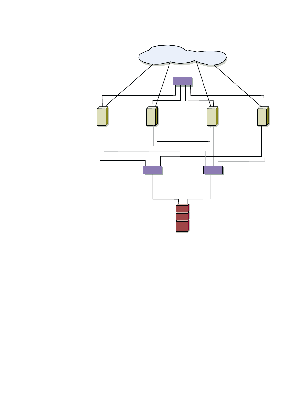
LAN/WAN
interconnect
switch
PowerEdge
server
PowerEdge
server
Fibre Channel
switch
PowerEdge
server
PowerEdge
server
Fibre Channel
switch
PowerVault
storage system
Figure 10-1. SAN-Attached Cluster Configuration
Fibre Channel Fabrics
A Fibre Channel switch fabric is an active, intelligent, and private connection of one or
more fibre channel switches that provide high-speed, point-to-point connections
between servers and storage devices. Using instructions that are programmed into
the switch, the switches in a Fibre Channel fabric provide a point-to-point connection
through inbound and outbound points from one device (sender) to another device or
switch (receiver) on the network. If the data is sent to another switch, the process
repeats itself until a connection is established between the sender and the receiver.
Fibre Channel switches are linked together using interswitched links (ISL). These ISLs
use two high-speed serial data connectors (HSSDC) or two subscriber connectors
(SC) to connect the switches. Each ISL is considered a “hop.” While a Fibre Channel
support.dell.com SAN Components 10-3
Page 80

switch fabric can support up to seven hops without performance degradation, a typical PowerVault SAN implementation usually includes fewer than seven hops.
Attaching a SAN-Attached Cluster Configuration to a Network
SAN-attached clusters are cluster configurations where redundant Fibre Channel
HBAs are cabled to a redundant Fibre Channel switch fabric. Connecting the cluster to
the storage system is achieved through the switch fabric. These SAN-attached configurations can share certain resources with other servers, storage systems, and backup
systems on the SAN.
SAN-attached cluster configurations can be attached to the following types of
networks:
• Public network - A network that connects the cluster nodes to the client network.
This network consists of devices such as Ethernet network interface controllers
(NIC) installed in the cluster nodes.
• Private network (node-to-node cluster interconnect) - A dedicated network that
connects the servers to each other. The primary function of the private network
in a cluster configuration is to pass heartbeat information that allows each cluster
node to monitor the health of the other cluster node.
• Storage area network (SAN) - A configuration of computer and storage systems
that incorporates dedicated Fibre Channel connectivity between the computer
systems and storage. A SAN bypasses traditional network bottlenecks and supports direct high-speed data transfer between the servers and storage devices.
NOTE: Each segment may vary in components and complexity.
Figure 10-2 shows a SAN-attached PowerEdge Cluster FE100/FL100 Datacenter configuration using three networking segments: public network, private network, and
SAN.
10-4 User’s Guide
Page 81
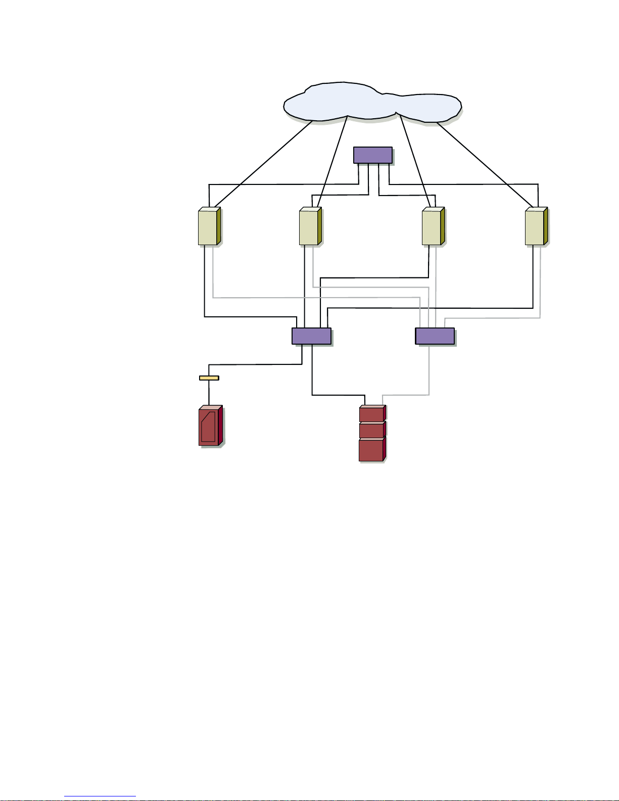
LAN/WAN
Interconnect
Switch
PowerEdge
server
PowerEdge
server
Fibre Channel
switch
Fibre Channel
bridge
PowerVa u lt 130T
PowerEdge
server
PowerEdge
server
Fibre Channel
switch
PowerVault storage
system
Figure 10-2. SAN-attached Clusters Using a Public, Private, and
SAN Network
support.dell.com SAN Components 10-5
Page 82

Using Dell PowerVault Fibre Channel
Switches
You can connect cluster nodes to the PowerVault shared storage system by using
redundant PowerVault Fibre Channel switches. When cluster nodes are connected to
the storage system through Fibre Channel switches, the cluster configuration is technically attached to a SAN.
To connect your cluster nodes to the PowerVault shared storage system, your system
must have the following hardware components:
• Two PowerVault 51F or 56F Fibre Channel switches (more switches may be nec-
essary depending on the configuration)
• Copper high-speed serial data connector (HSSDC) or fibre optic cables to connect
the cluster nodes to the Fibre Channel switches
• Copper cables with an HSSDC connector on one end and a DB-9 connector on
the other to connect the Fibre Channel switch to the PowerVault storage systems
Attaching a PowerVault Storage System to
a SAN-Attached Cluster
The following sections provide configuration and cabling examples for attaching a
PowerVault storage system to a SAN-attached cluster.
Connecting the PowerEdge Cluster to a Single
PowerVault Storage System
You can add fast and reliable data redundancy to your cluster configuration by adding a
PowerVault storage system. This configuration allows you to share the SAN with
other clusters and servers, thereby adding scalability to your cluster configuration.
To attach a PowerVault storage system to your cluster, connect each cluster node to
both Fibre Channel switches and connect each Fibre Channel switch to the
PowerVault storage processors on the cluster's shared storage.
An example of a PowerVault storage system attached to a PowerEdge cluster is
shown in Figure 10-2.
10-6 User’s Guide
Page 83

Connecting a PowerVault 130T DLT Library and
PowerVault 35F Fibre Channel Bridge to a ClusterAttached PowerVault SAN
You can add tape backup devices to your PowerVault SAN to provide additional backup
to your cluster. To implement this configuration, use the PowerVault 35F Fibre Channel SCSI bridge to support the PowerVault 130T DLT library on PowerEdge Cluster
FE100 Datacenter Server configurations.
Figure 10-2 shows a supported PowerEdge Cluster FE100/FL100 Datacenter configuration using redundant Fibre Channel switches, Fibre Channel bridge, and PowerVault
130T DLT library. In this configuration, each of the cluster nodes is attached to the
backup device and the backup local disk resources, as well as to the owned cluster
disk resources. Using this configuration provides you the ability to add more servers
and storage systems in the future, if needed.
NOTES: See the storage and tape backup documentation for more information on
configuring these components.
Contact the tape backup software vendor for more information on using your software
in a cluster configuration.
The PowerVault 35F Fibre Channel SCSI bridge, the PowerVault 130T DLT library, and
their cables are made through a single switch fabric and do not comprise a redundant
configuration. Therefore, tape backups may be incomplete if one of these components fails.
Configuring Hard-Disk Drive Letters Using Multiple
Shared Storage Units
Before installing the Cluster Service, ensure that both nodes have the same view of
the shared storage. Because each node has access to hard-disks that are in a common storage array, each node must be assigned identical hard-disk drive letters.
To ensure that the hard-disk drive letter assignments for the cluster nodes, perform
the following procedures:
1. Ensure that your cables are connected properly.
The Windows 2000 Disk Management utility displays all of the accessible disks
attached to the first QLogic HBA, followed by those that are accessible from the
second QLogic HBA.
On the first HBA, the attached disks will be displayed numerically, starting with
the lowest port number.
2. Ensure that the first QLogic HBA detected by each cluster node is connected to
the switch attached to PowerVault storage processor A.
3. Ensure that the second QLogic HBA detected by each cluster node is connected
to the switch attached to the PowerVault storage processor B.
support.dell.com SAN Components 10-7
Page 84

4. Assign drive letters and volume labels to the disks.
To assign drive letters and volume labels to the disks, perform the following
steps:
a. Power down all cluster nodes except node 1.
b. Assign drive letters on node 1, using the Windows 2000 Disk Management
utility to create the drive letters and volume labels.
For example, create volumes labeled “Volume E” for disk E and “Volume F”
for disk F.
c. Power down the cluster node.
d. Power on the next cluster node and start the Windows 2000 Disk
Management utility. Assign the drive letters to the shared disks and shutdown the node.
e. Repeat step d for each remaining node.
The drive letter assignment should be performed on each of the shared
disks, even if the disk displays the drive letter correctly.
If the cables are connected properly, the drive order will be the same on all nodes,
and the drive letter assignments should follow the same order on all nodes.
The volume labels can also be used to double-check the drive order by ensuring that
the disk volume label is assigned to an identical drive letter for each node.
Additional PowerEdge Cluster
Maintenance Procedures
The following section provide procedures for maintaining your PowerEdge
Cluster FE100/FL100 Datacenter Server configurations.
Using the QLogic Fibre Channel Configuration Utility for
Storage Processor Failure
For more information on installing QLogic Fibre Channel Configuration Utility, see the
Dell PowerVault Systems Storage Area Network (SAN) Installation and
Troubleshooting Guide.
10-8 User’s Guide
Page 85

APPENDIX A
Troubleshooting
This appendix provides troubleshooting information for the Dell PowerEdge Cluster
FE100/FL100 Datacenter configurations. Table A-1 describes general cluster problems
you may encounter and the probable causes and solutions for each problem. Table A2 is specific to Windows 2000 cluster configurations.
Table A-1. General Cluster Troubleshooting
Problem Probable Cause Corrective Action
The nodes cannot access the
Dell PowerVault storage system, or the cluster software is
not functioning with the storage system.
One of the nodes takes a long
time to join the cluster.
The PowerVault storage
system is not cabled properly to the nodes or the
cabling between the
PowerVault components is
incorrect.
The length of the interface
cables exceeds the maximum allowable length.
One of the cables is faulty.
The node-to-node network
has failed due to a cabling or
hardware failure.
Long delays in node-to-node
communications may be
normal.
Make sure that the cables are connected
properly from the node to the PowerVault
storage system. See the cabling instructions in “Cabling the Cluster Hardware” in
Chapter 4 of this guide.
Ensure that copper cables do not exceed
30 meters (m).
Replace the faulty cable.
Check the network cabling. Ensure that
the node-to-node interconnection and the
public local area network (LAN) are connected to the correct network interface
controllers (NICs).
Verify that the nodes can communicate
with each other by running the ping command from each node to the other node.
Try both the host name and Internet Protocol (IP) address when using the ping
command.
support.dell.com Troubleshooting A-1
Page 86

Table A-1. General Cluster Troubleshooting (continued)
Problem Probable Cause Corrective Action
Attempts to connect to a cluster using Cluster Administrator
fail.
You are prompted to configure
one network instead of two
during Microsoft Cluster Server
installation.
The Cluster Service has not
been started.
A cluster has not been
formed on the system.
The system has just been
booted and services are still
starting.
The Transmission Control
Protocol (TCP)/IP configuration is incorrect.
Verify that the Cluster Service is running
and that a cluster has been formed. Use
the Event Viewer and look for the follow-
ing events logged by the Cluster Service:
Microsoft Cluster Server successfully formed a cluster on
this node.
or
Microsoft Cluster Server successfully joined the cluster.
If these events do not appear in Event
Viewer, see the Microsoft Cluster Server
Administrator’s Guide for instructions on
setting up the cluster on your system and
starting the Cluster Service.
The node-to-node network and public LAN
must be assigned static IP addresses on
different subnets. See “Configuring the
System Software” in Chapter 6 of this
guide for information about assigning the
network IPs.
Troubleshooting Windows 2000
This section provides troubleshooting information for Dell PowerEdge Cluster FE100/
FL100 Datacenter Server configurations specific to the Windows 2000 operating
system.
Table A-2. Windows 2000 Troubleshooting
Problem Probable Cause Corrective Action
Using Windows NT 4.0 to
remotely administer a
Windows 2000 cluster generates error messages.
Normal. Some resources in
Windows 2000 are not in
Windows NT 4.0.
Dell strongly recommends that you use
Windows 2000 for remote administration
of a cluster running either version of the
Windows 2000 operating system.
A-2 Dell Dimension Systems User’s Guide
Page 87

APPENDIX B
Cluster Data Sheets
The configuration matrix and data sheets on the following pages are provided for the
system installer to record pertinent information about PowerEdge FE100/FL100 Datacenter Server Cluster configurations. The data sheets are for installing Microsoft
Windows 2000 Datacenter Server clusters.
Make a copy of the appropriate data sheet to use for the installation or upgrade, complete the requested information on the sheet, and have the completed sheet available
if you need to call Dell for technical assistance.
PowerEdge Cluster FE100/FL100
Datacenter Server Configuration Matrix
You can attach the following form to the back of each cluster node or rack. The system
installer may want to use the form to record important information about the hardware on each cluster component. In addition, Dell recommends that you have a copy
of the form available any time you call Dell for technical support.
support.dell.com Cluster Data Sheets B-1
Page 88

Table B-1. PowerEdge Cluster FE100/FL100 Configuration Matrix
Cluster Type PowerEdge Cluster FE100/FL100 Datacenter Server
Cluster Name
Installer
Date Installed
Applications
Location
Notes
Node PowerEdge Server Model Windows 2000 Name
Node 1
Node 2
Node 3
Node 4
Storage Array Description (Drive letters, RAID ty pes , a pplic atio ns/d ata ins talle d)
Storage
Component: Node 1 Node 2 Storage
Service Tag
System Storage
Node 1, HBA 1 Switch 1
Node 2, HBA 1 Switch 1
Node 3, HBA 1 Switch 1
Node 4, HBA 1 Switch 1
Node 1, HBA 2 Switch 2
Node 2, HBA 2 Switch 2
Node 3, HBA 2 Switch 2
Node 4, HBA 2 Switch 2
PCI Slot
Adapter Installed Usage
Number
PCI slot 1
PCI slot 2
PCI slot 3
PCI slot 4
PCI slot 5
PCI slot 6
PCI slot 7
PCI slot 8
PCI slot 9
PCI slot 10
(Public Network, Private Network,
Shared Storage, and Internal Drives)
B-2 User’s Guide
Page 89

Cluster Data Sheets
The data sheets on the following pages are provided for the system installer to record
applicable information about the PowerEdge Cluster FE100/FL100 Datacenter configuration. The data sheets are for installing Windows 2000 Datacenter Server clusters.
Make a copy of the appropriate data sheet to use for the installation or upgrade.
Complete the requested information on the sheet and have the completed sheet
available if you need to call Dell for technical assistance.
Dell PowerEdge Cluster FE100/FL100 Installer Data Sheet and Checklist for a
Complete Installation on Windows 2000 Datacenter Serve
Instructions: Before configuring the systems for clustering, use this checklist to gather information and
prepare your systems for a successful installation. This data sheet assumes you are installing the server
cluster for the first time.
Ensure that all equipment is present and properly cabled and that you know how to install Windows 2000
Datacenter Server. Make sure each of the procedures listed below is performed correctly.
Pre-Installation Settings
GConfirm that both nodes and the storage system meet the PowerEdge Cluster FE100/FL100 minimum
configuration requirements.
r
G Place NICs that support hot-plug peripheral component interconnect (HPPCI) in PCI slots that support
HPPCI, if available and if supported for the configuration.
GCable the system hardware for clustering.
Configure Storage Subsystem Components
GConfigure and initialize the shared RAID volumes.
support.dell.com Cluster Data Sheets B-3
Page 90

Windows 2000 Datacenter Server Operating System Installation and Configuration
Install Windows 2000 Datacenter Server, including:
GNetwork name for node 1_________________________________
GNetwork name for node 2_________________________________
GNetwork name for node 3_________________________________
GNetwork name for node 4_________________________________
GSelect Cluster Service during initial installation.
GNode 1 network IP configuration:
Public network IP Address: ___.______._____.____
Subnet Mask: 255.______._____._____
Primary DNS Server: _____.______._____.____
Secondary DNS Server: _____.______._____.____
Primary WINS Server: _____.______._____.____
Secondary WINS Server: _____.______._____.____
GNode 2 network IP configuration:
Public network IP Address: ______.______._____._____
Subnet Mask: 255.______._____._____
Primary DNS Server: ______.______._____._____ (same IP address as node 1)
Secondary DNS Server: _____.______._____._____ (same IP address as node 1)
Primary WINS Server: ______.______._____.____ (same IP address as node 1)
Secondary WINS Server: _____.______._____.____ (same IP address as node 1)
GNode 3 network IP configuration:
Public network IP Address: ______.______._____._____
Subnet Mask: 255.______._____._____
Primary DNS Server: ______.______._____._____ (same IP address as node 1)
Secondary DNS Server: _____.______._____._____ (same IP address as node 1)
Primary WINS Server: ______.______._____.____ (same IP address as node 1)
Secondary WINS Server: _____.______._____.____ (same IP address as node 1)
B-4 User’s Guide
Page 91

Windows 2000 Datacenter Server Operating System Installation and Configuration
(Continued)
GNode 4 network IP configuration:
Public network IP Address: ______.______._____._____
Subnet Mask: 255.______._____._____
Primary DNS Server: ______.______._____._____ (same IP address as node 1)
Secondary DNS Server: _____.______._____._____ (same IP address as node 1)
Primary WINS Server: ______.______._____.____ (same IP address as node 1)
Secondary WINS Server: _____.______._____.____ (same IP address as node 1)
GConfigure domain membership.
GPartition, format (NTFS), and assign drive letters to the shared drives using the Windows 2000 Disk
Management tool.
GDrive letters for PowerVault 65xF shared storage:
No. 1 __________ No. 2 __________No. 3 __________ No. 4 __________
No. 5 __________ No. 6 __________No. 7 __________ No. 8 __________
No. 9 __________ No. 10_________ No. 11__________No. 12 __________
No. 13__________No. 14_________ No. 15__________No. 16 __________
No. 17__________No. 18_________ No. 19__________No. 20__________
No. 21__________No. 22_________
Cluster Service Configuration
GCreate a new cluster.
GName the cluster.
GAssign a network account for the Cluster Service.
GAssign the location of the quorum disk.
Name each of the installed network segments:
GName of network 1 is Public (for local are network [LAN] interconnect).
GName of network 2 is Private (for node-to-node interconnect).
GName of network 3 (for a connection to an additional public network).
support.dell.com Cluster Data Sheets B-5
Page 92

Cluster Service Configuration (Continued)
GName of network 2 is Private (for node-to-node interconnect).
GAssign a static IP address for management:
Management IP Address: ______.______._____._____
Subnet Mask: 255.______._____._____
GJoin the cluster.
Post-Microsoft Cluster Service Installation
GReapply the latest Windows 2000 service pack.
GInstall Dell OpenManage Cluster Assistant With ClusterX on management client (optional).
GInstall and configure cluster application programs.
B-6 User’s Guide
Page 93

Dell PowerEdge Cluster FE100/FL100 Installer Data Sheet and Checklist for an
Upgrade Installation to Windows 2000 Datacenter Server
Instructions: Before configuring the systems for clustering, use this checklist to gather information and
prepare your systems for a successful installation. This data sheet assumes that Windows 2000 Datacenter
Server was factory or customer installed on each node. If you are installing these systems for the first time,
use the complete installation data sheet.
Pre-Installation Settings
GAdd NICs, hard-disk drives and all other hardware components to both nodes and the storage system to
meet the PowerEdge Cluster FE100/FL100 minimum configuration requirements.
GCable the system hardware for clustering.
Windows 2000 Datacenter Server Settings
GServers are added to a domain. Domain name: ____________________________
GWindows 2000 service pack is installed.
GThe drivers for your BroadCom NetExtreme Gigabit Ethernet NIC or Giganet cLAN 1000 adapter for the
private NIC are the latest versions.
GNetwork protocol is TCP/IP only. Uninstall all other protocols.
GA static TCP/IP address is required for each NIC:
Node 1, NIC 1, IP Address: ______.______._____._____
Subnet Mask: 255.______._____._____
Node 2, NIC 2, IP Address: ______.______._____._____
Subnet Mask: 255.______._____.____
Node 3, NIC 1, IP Address: ______.______._____.______
Subnet Mask: 255.______._____.______
Node 4, NIC 2: IP Address: ______.______.______.______
Subnet Mask: 255.______._____._____
GVerify TCP/IP connectivity to the network and on each node.
support.dell.com Cluster Data Sheets B-7
Page 94

Configuring the Shared Storage System
GConfigure and initialize the RAID volumes.
GThe format of the PowerVault shared storage is NTFS.
GDrive letters for the PowerVault storage system:
No. 1 __________No. 2 _________ No. 3 __________ No. 4 __________
No. 5 __________No. 6 __________ No. 7 __________ No. 8 __________
No. 9__________ No. 10 _________ No. 11 _________ No. 12__________
No. 13_________ No. 14__________No. 15__________No. 16 __________
No. 17_________ No. 18__________No. 19 _________ No. 20__________
No. 21_________ No. 22__________
Microsoft Cluster Service Installation
GCluster name: _____________________________
GCluster Service account: ________________________
GCluster Service password: ________________________
NOTE: To maintain system security, record the Cluster Service account name and password and keep
them in a safe location.
GName of network 1 is Public (for the LAN interconnect).
GName of network 2 is Private (for node-to-node interconnect):
Cluster, IP Address: _____.______._____._____
Subnet Mask: 255.______._____._____
Post-Microsoft Cluster Service Installation
GVerify the functionality of the cluster.
GInstall and set up your cluster application programs.
GInstall Dell OpenManage Cluster Assistant With ClusterX on management client (optional).
B-8 User’s Guide
Page 95

Index
B
Broadcom NetExtreme Gigabit Ethernet
NIC
in your private network, 1-5, 1-11, 1-13,
4-1
cabling, 4-3
implementing, 4-3
in your public network, 1-12, 4-3
C
cabling in a Dell rack, 4-6
cluster administrator
about, 7-1
installing on a remote console
running Windows 2000 Advanced
Server, 7-2
running Windows 2000
Professional, 7-1
running Windows NT 4.0 Server,
Enterprise Edition, 7-2
running on a cluster node, 7-1
cluster cabling components
about, 4-1
cluster configurations
about, 1-5
verifying cluster readiness, 6-13
cluster quorum resource
adding additional applications and data,
6-14
cluster resource group, 6-14
connectors
DB9, 4-2
fibre-channel, 4-2
HSSDC (high speed serial data
connector), 4-2
D
Dell OpenManage software
application transparent failover (ATF),
6-9
restoring to a failed storage device,
9-3
cluster assistant with ClusterX
about, 7-3
installing, 7-3
data administrator, 6-10
connecting to data agent, 9-2
data supervisor, 6-10
connecting to data agent, 9-3
installation overview, 2-1
installing, 6-9
managed node (data agent), 6-10
configuring for cluster failover, 6-16
configuring for clustering, 6-16
connecting to PowerVault shared
storage systems, 9-1
connecting to the PowerVault
shared storage systems, 9-1
required applications, 1-12
to connect to your PowerVault shared
storage systems, 9-1
support.dell.com Index 1
Page 96

Dell PowerEdge Clusters FE100/FL100
Datacenter Server
about, 1-2
cabling your private network, 4-3
cabling your public network, 4-3
configuration requirements, 1-13
configurations, 1-5
installation overview, 2-1
Dell PowerVault SAN
about, 10-1
SAN-attached clusters, 10-2
attaching to the network, 10-4
Dell PowerVault storage area network
(SAN)
components, 10-1
G
Giganet cLAN NIC
in your private network, 1-5, 1-11, 1-13
in your public network, 4-3
upgrading to Windows 2000
Datacenter Server, 7
I
Intel PRO/1000 Gigabit Server Adapter
in your public network, 1-12
disk management tool, 6-11
determining RAID levels of the shared
disk volumes, 9-4
domain controllers, 6-2
E
execution throttle values, 2-1
F
failover
options, 1-6
using 4-node clustering, 6-18
fibre channel fabrics, 10-3
fibre-channel switches
about, 10-6
four-node clustering configurations
cascading failover, 1-8
multiway failover, 1-7
n+1 failover, 1-6
n-way failover, 1-9
M
member servers, 6-2
N
NICs
Broadcom NetExtreme Gigabit
Ethernet
cabling the private network, 4-3
in your private network, 1-5, 1-11, 4-
1
in your public network, 1-12, 4-3
Giganet cLAN
in your private network, 1-13
Intel PRO 1000 Gigabit Server Adapter
in your public network, 1-12
P
peripherals
adding, 3-1
power failure protection, 4-5
standby power supplies (SPS), 4-5
2 User’s Guide
Page 97

PowerEdge clusters
about, 1-2
active/active configurations, 1-5
active/passive configurations, 1-5
adding cluster peripherals, 3-1
additional maintenance procedures,
10-8
attaching one cluster to one
PoweVault storage system, 10-6
configuring enclosure addresses, 3-2
configuring Fibre Channel HBAs, 3-2
preparing for clustering, 3-1
SAN-attached cluster configurations,
1-3
SAN-attached clusters
attaching a PowerVault storage
system, 10-6
upgrading to a FE100/FL100
configuration requirements, 1-13
PowerEdge system
upgrading to a FE100/FL100
Datacenter Server configuration,
8-1
PowerEdge systems
about Windows 2000 platforms, 8-2
upgrading to a cluster configuration, 8-
1
upgrading to a FE100/FL100
Datacenter Server configuration,
8-1
PowerVault 65xF storage system
replacing the storage processor, 9-4
PowerVault storage area network (SAN)
about, 10-1
private network
cabling, 4-3
configuring the IP addresses, 6-5
configuring using Windows 2000, 6-4
hardware components, 1-11
using Broadcom Gigabit NICs, 4-3
using cLAN Giganet, 4-4
verifying cluster readiness, 6-15
verifying Cluster Service, 6-15
public network
cabling, 4-3
hardware components, 1-12
using NICs, 4-3
verifying cluster readiness, 6-15
verifying cluster resource availability,
6-15
verifying Cluster Service, 6-15
Q
QLConfig
about, 9-4
replacing the PowerVault 65xF storage
processor, 9-4
R
racks
cabling your mouse, keyboard, and
monitor, 4-6
replacing a cluster node, 9-8
PowerVault storage systems
adding to cluster, 3-1
configuring enclosure addresses, 3-2
configuring Fibre Channel HBAs, 3-2
connecting a tape library and bridge to
a cluster-attached PowerVault
SAN, 10-7
low-level configurations, 5-1
preparing for clustering, 3-1
shared storage requirements, 1-14
support.dell.com Index 3
S
SAN-attached cluster configuraitons
hardware requirements, 1-15
SAN-attached cluster configurations, 1-3
attaching a PowerVault storage
system, 10-6
storage processor failure
recovery procedures, 9-4
Page 98

switches
about, 10-6
T
troubleshooting, 1
connecting to a cluster, 2
shared storage subsystem, 1
U
uninterruptible power supplies (UPS), 4-5
V
virtual servers, 1-2
W
Windows 2000 Datacenter Server
about, 1-1
configuring the nodes, 6-2
configuring the public and private
networks, 6-4
configuring your cluster nodes, 9-5, 9-8
adding a third NIC to a cluster node,
9-5
changing the IP address, 9-7
running chkdsk /f on a quorum disk,
9-8
uninstalling the Cluster Service
(MSCS), 9-8
failover and failback support, 1-6
failover support through 4-node
clustering, 6-18
installing Cluster Service, 6-13
installing the Cluster Service (MSCS),
6-3
minimum system requirements, 1-11
cluster client network connections
(public network), 1-12
cluster interconnect (private
network), 1-11
cluster nodes, 1-11
cluster storage, 1-11
operating system and system
management software, 1-12
network install and configuration, 6-6
network installation overview, 6-6
preparing to install, 6-1
updating the host bus adapter (HBA),
6-8
using dynamic disks and volumes, 6-12
using the disk management tool, 6-11
4 User’s Guide
 Loading...