

Dell PowerConnect W-IAP175P, PowerConnect W-IAP175 Installation Manual

Dell PowerConnect W-IAP175 Outdoor Instant Access Point
Installation Guide
The Dell PowerConnect W-IAP175 is a resilient, environmentally hardened, outdoor rated, dual-radio, dual-band
IEEE 802.11 a/b/g/n wireless access point. This outdoor access point is part of Dell’s comprehensive wireless
network solution.
NOTE: The W-IAP175 requires Instant 3.0 or later.
There are three versions of the W-IAP175, which mainly differ in the way they receive power.
W-IAP175P: PoE+ powered (802.3at)
W-IAP175AC: AC powered (100-240 V AC)
NOTE: The W-IAP175AC can function as a Power Sourcing Equipment (PSE) device by providing power through its ethernet port in
compliance with the IEEE 802.3af standard.
Guide Overview
“W-IAP175 Hardware Overview” on page3 provides a detailed hardware overview of the three W-IAP175
models.
“Outdoor Planning and Deployment Considerations” on page7 provides key questions to ask and items to
consider when deploying an outdoor wireless network.
“Installing Antennas” on page12 describes how to installing antennas.
“Weatherproofing Connections” on page12 provides instructions on weatherproofing the AP’s connectors.
“Installing the W-IAP175” on page20 describes the multi-step process for a successful installation and
deployment of an W-IAP175.
“Safety and Regulatory Compliance” on page30 provides an overview of safety and regulatory compliance
information.
W-IAP175 Operations
Wireless access point (IEEE 802.11 a/b/g/n)
Wireless air monitor (IEEE 802.11 a/b/g/n)
Enterprise mesh point
Enterprise mesh portal
Protocol-independent networking functionality
W-IAP175P: IEEE 802.3at Power over Ethernet+ (PoE+) compatible
W-IAP175AC: IEEE 802.3af Power Sourcing Equipment (PSE) device
0511155-01 | September 2012 1

Package Contents
W-IAP175 Access Point
W-IAP175 Mounting Bracket
Solar Shield
Pole Anchors x 2
M4 x 16 bolts, flat washers, and spring washers x4 (These bolts are attached to the solar shield)
M6 x 30 bolts, flat washers, and spring washers x2
M4 x 12 bolt, external-tooth washer, and OT copper lug x1
M8 x 110 bolt, flat washers, spring washers, and nuts x4
Metal Weatherproof Caps x2 for use on unused antenna interfaces
RJ-45 Connector Kit with plastic RJ-45 connector (W-IAP175P only)
RJ-45 Connector Kit with metal RJ-45 connector (W-IAP175AC only)
USB Console Cable
Installation Guide
NOTE: Inform your supplier if there are any incorrect, missing, or damaged parts. If possible, retain the carton, including the
original packing materials. Use these materials to repack and return the unit to the supplier if needed.
2 Dell PowerConnect W-IAP175 Outdoor Instant Access Point | Installation Guide
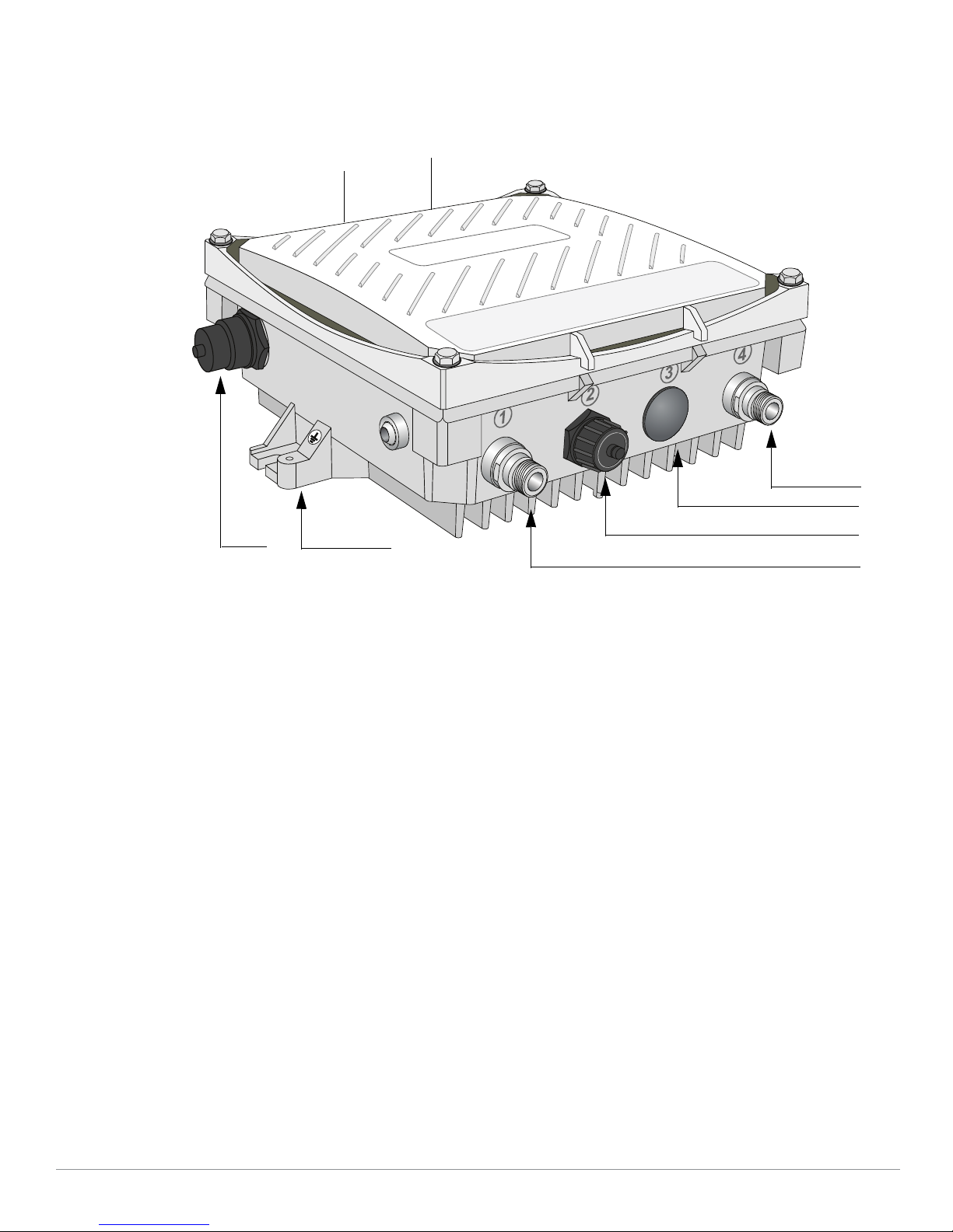
W-IAP175 Hardware Overview
2
1
3
4
8
7
6
5
The following section describes the hardware features of the W-IAP175.
Figure 1
W-IAP175 Overview (W-IAP175P shown)
1 Antenna Interface (Radio 1) 5 Antenna Interface (Radio 0)
2 USB Console Interface 6 Antenna Interface (Radio 1)
3 Reserved (W-IAP175P) or
Power Interface (W-IAP175AC)
4 Antenna Interface (Radio 0) 8 Grounding Point
Antenna Interface
The W-IAP175 requires the use of detachable outdoor-rated antennas. Select the correct antenna type to support
7 Ethernet Interface (PoE)
the required frequency band (2.4 or 5 GHz) and the desired coverage pattern.
The W-IAP175 is equipped with four, female N-type antenna interfaces; two on the top of the AP and two on the
bottom. The interfaces are grouped into diversity pairs, one pair is marked R0 (Radio 0) and the other pair
marked as R1 (Radio 1). R0 supports the 5 GHz frequency band and R1 supports the 2.4 GHz radio band.
Dell PowerConnect W-IAP175 Outdoor Instant Access Point | Installation Guide 3

USB Console Interface
A USB serial console port is provided for connection to a terminal, allowing direct local management. Use the
included USB console cable to connect to the AP. You can download the necessary driver for USB-UART adapter
from download.dell-pcw.com under Tools & Resources.
Use the following setting to access the terminal:
Table 1
Console Settings
Baud Rate Data Bits Parity Stop Bits Flow Control
9600 8 None 1 None
Power Interface
The type of power interface on your W-IAP175 depends on which model you have purchased.
W-IAP175P: This version does not include a power interface since it is only powered by PoE+ (802.3at).
W-IAP175AC: 1x AC power connector
CAUTION: Do not connect a DC power cable to an W-IAP175AC.
NOTE: The W-IAP175 does not ship with any power cables; these are available as accessories and should be ordered separately.
In addition to completed power cables, Dell also offers an outdoor rated AC connector kit that can be used to connect a
compatible power cable to the W-IAP175.
AC Power Connections
The W-IAP175AC product offering offers two ways to connect the unit to AC power. Two power cord variants are
offered and a connector kit that allows the customer to assemble their own cable if the standard offering does not
meet deployment needs
The applicable SKUs for these options are:
Table 2
SKUs for Powering Options
Part Number Description
CBL-AC-NA Weatherproof AC power cable (5m), North America version
CBL-AC-INTL Weatherproof AC power cable (5m), International (EU)
version
CKIT-AC-M Weatherproof connector kit for AC power interface
The difference between the NA and INTL part variants is the color coding of the conductors.
The North American cable uses Black (Hot), White (Neutral), and Green (Ground).
The INTL part follows the international schema of Brown (Hot), Blue (Neutral) and Yellow/Green (Ground)
Ethernet Interface
The W-IAP175 is equipped with a 10/100/1000Base-T Gigabit Ethernet port for wired network connectivity. On
the W-IAP175P, this port also supports IEEE 802.3at Power over Ethernet (PoE), accepting 48 VDC as a
standards-defined powered device (PD) from a power sourcing equipment (PSE) device, such as a PoE midspan
4 Dell PowerConnect W-IAP175 Outdoor Instant Access Point | Installation Guide
injector. Inversely, the W-IAP175AC can act as a PSE device to provide IEEE802.3af PoE power to devices
P/S
ENT
POE
RSSI for Radio 1
RSSI for Radio 0
connected to the ethernet port.
Grounding Point
Always remember to protect your W-IAP175 by installing grounding lines. The ground connection must be
complete before connecting power to the W-IAP175 enclosure. Ensure that the resistance is less than 5 ohm
between the ground termination point and the grounding tier.
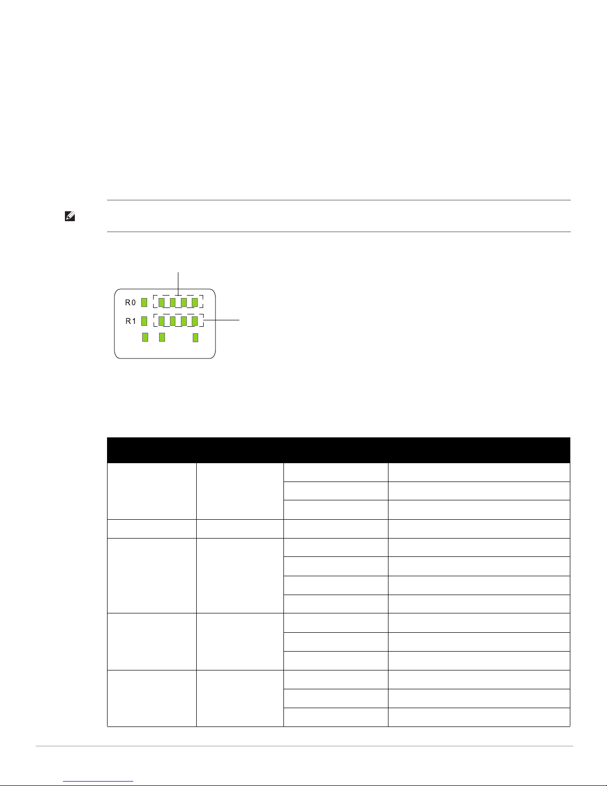
W-IAP175P LED Status Indicators
The W-IAP175 include visual indicators for power, link, and radio status. Additionally, each radio has a four-LED
array that indicates received signal strength (RSSI).
NOTE: The RSSI LED indicators represent varying degrees in the RSSI level. The absence of a signal is indicated by no LED
response, and full signal strength is indicated when all four LEDs are active and lit.
Figure 2
LED Layout
Table 3 lists the meanings of the LEDs on the W-IAP175P outdoor access point.
Table 3
W-IAP175P LED Status Indicators
LED Function Indicator Status
P/S AP Power/Ready
Status
POE N/A N/A Not currently used
Off No power to AP
Blinking Device booting, not ready
On Device ready
ENT LAN/Network Link
R0 Radio 0 Status Off Radio 0 disabled
R1 Radio 1 Status Off Radio 1disabled
Dell PowerConnect W-IAP175 Outdoor Instant Access Point | Installation Guide 5
Status
Off Ethernet link unavailable
On (Amber) 10/100 Mbs ethernet link negotiated
On (Green) 1000 Mbs ethernet link negotiated
Blinking Traffic on ethernet link
On (Amber) Radio 0 enabled in WLAN mode
Blinking Air Monitor (AM) mode
On (Blue) Radio 1 enabled in WLAN mode
Blinking Air Monitor (AM) mode
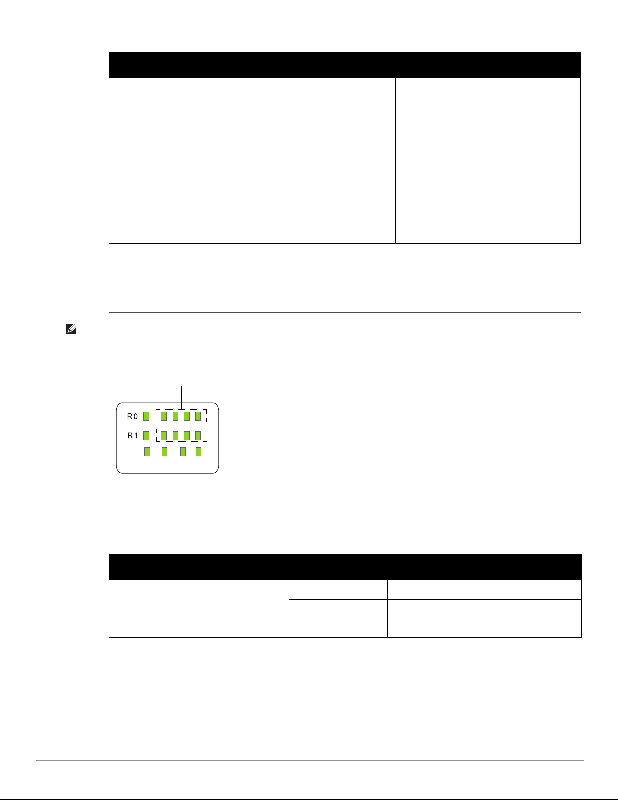
Table 3
P/S
ENT
POE HEAT
RSSI for Radio 1
RSSI for Radio 0
W-IAP175P LED Status Indicators (Continued)
LED Function Indicator Status
RSSI (Radio 0) RSSI Level for Radio 0 Off RSSI disabled/no signal
4 Step Progressive Bars
(Red)
25/50/75/100%
RSSI (Radio 1) RSSI Level for Radio 1 Off RSSI disabled/no signal
4 Step Progressive Bars
(Blue)
25/50/75/100%
Each bar represents a progressive increase in
signal strength, with 4 bars representing
maximum signal strength (100%).
Minimum data rate: One lit LEDs
Maximum data rate: Four lit LEDs
Each bar represents a progressive increase in
signal strength, with 4 bars representing
maximum signal strength (100%).
Minimum data rate: One lit LEDs
Maximum data rate: Four lit LEDs
W-IAP175AC LED Status Indicators
The W-IAP175 include visual indicators for power, link, heat and radio status. Additionally, each radio has a fourLED array that indicates received signal strength (RSSI).
NOTE: The RSSI LED indicators represent varying degrees in the RSSI level. The absence of a signal is indicated by no LED
response, and full signal strength is indicated when all four LEDs are active and lit.
Figure 3
LED Layout
Table 4 lists the meanings of the LEDs on the W-IAP175AC outdoor access points.
Table 4
W-IAP175AC LED Status Indicators
LED Function Indicator Status
P/S AP Power/Ready
Status
6 Dell PowerConnect W-IAP175 Outdoor Instant Access Point | Installation Guide
Off No power to AP
Blinking Device booting, not ready
On Device ready

Table 4
W-IAP175AC LED Status Indicators (Continued)
LED Function Indicator Status
POE Displays PSE power
output status
Heat Displays the heating
status of low
temperature
ENT LAN/Network Link
Status
R0 Radio 0 Status Off Radio 0 disabled
Off Non-powered device (0Ω<Rport<200Ω) or Port
open (Rport>1MΩ)
Green Port on (25kΩ)
1 Flash: Low signature resistance
(300Ω<Rport<15kΩ)
2 Flashes: High signature resistance
(33kΩ<Rport<500kΩ)
5 Flashes: Port overload fault
9 Flashes: Power management allocation
exceeded
Off Unit is not in heating status
Blinking (Blue) Unit is pre-heating
Off Ethernet link unavailable
On (Amber) 10/100 Mbs ethernet link negotiated
On (Green) 1000 Mbs ethernet link negotiated
Blinking Traffic on ethernet link
On (Amber) Radio 0 enabled in WLAN mode
Blinking Air Monitor (AM) mode
R1 Radio 1 Status Off Radio 1disabled
On (Blue) Radio 1 enabled in WLAN mode
Blinking Air Monitor (AM) mode
RSSI (Radio 0) RSSI Level for Radio 0 Off RSSI disabled/no signal
4 Step Progressive Bars
(Red)
25/50/75/100%
RSSI (Radio 1) RSSI Level for Radio 1 Off RSSI disabled/no signal
4 Step Progressive Bars
(Blue)
25/50/75/100%
Each bar represents a progressive increase in
signal strength, with 4 bars representing maximum
signal strength (100%).
Minimum data rate: One lit LEDs
Maximum data rate: Four lit LEDs
Each bar represents a progressive increase in
signal strength, with 4 bars representing maximum
signal strength (100%).
Minimum data rate: One lit LEDs
Maximum data rate: Four lit LEDs
Outdoor Planning and Deployment Considerations
Prior to deploying an outdoor wireless network, the environment must be evaluated to plan for a successful Dell
WLAN deployment. Successfully evaluating the environment enables the proper selection of Dell APs and
antennas and assists in the determination of their placement for optimal RF coverage. This process is considered
WLAN or RF planning.
Dell PowerConnect W-IAP175 Outdoor Instant Access Point | Installation Guide 7

Scale Requirements
The potentially immense scale of outdoor deployments requires consideration of factors that may not be as
important in a typical indoor deployment:
Range (distance): Range or distance between APs must be taken into account during the planning phase.
Available AP mounting locations are often far less flexible in an outdoor environment. Regardless of these
outdoor restrictions, the desired goal is to achieve results similar to an indoor deployment: a “dense” RF
deployment that supports advanced Aruba features, such as ARM, efficient client roaming, and failover.
Elevation: Proper consideration and planning for elevation differences between APs (AP to AP) and AP to
Client can be critical to success. To plan for these differences in elevation, it is important to understand the
3D coverage pattern provided by the antennas that will be deployed in the environment.
Non-Fixed Considerations: The RF environment might change on a day to day basis. Keep non-fixed items,
such as shipping containers, vehicles, and future building construction, in mind when planning for an outdoor
deployment.
Identifying Known RF Absorbers/Reflectors/Interferences Sources
Identifying known RF absorbers/reflectors/interference sources while out in the field during the installation phase
is critical. Even though outdoor environments consist of fewer RF absorbers/reflectors/interference sources
compared to indoor environments, ensure that these sources are identified and taken into consideration when
installing and mounting an AP to its fixed outdoor location.
RF Absorbers
Cement/Concrete
Natural Items: Trees/vegetation
Brick
RF Reflectors
Metal Objects: Roof-installed air-conditioning equipment, chain link fences (depending on aperture size),
other wire fences, or water pipes
RF Interference Sources
Other 802.11a/b/g/n or broadband access equipment operating nearby
Industrial RF welding equipment or other Industrial, Scientific and Medical (ISM) equipment that utilizes
RF to heat or alter the physical properties of materials
Military, Commercial Aviation or Weather Radar Systems
Line of Sight (Radio Path Planning)
A wireless bridge or mesh link requires a “radio line of sight” between the two antennas for optimum
performance. The concept of radio line of sight involves the area along a link through which the bulk of the radio
signal power travels. This area is known as the first Fresnel Zone of the radio link. For a radio link, no object
(including the ground) must intrude within 60% of the first Fresnel Zone.
Figure 4 illustrates the concept of a good radio line of sight.
8 Dell PowerConnect W-IAP175 Outdoor Instant Access Point | Installation Guide
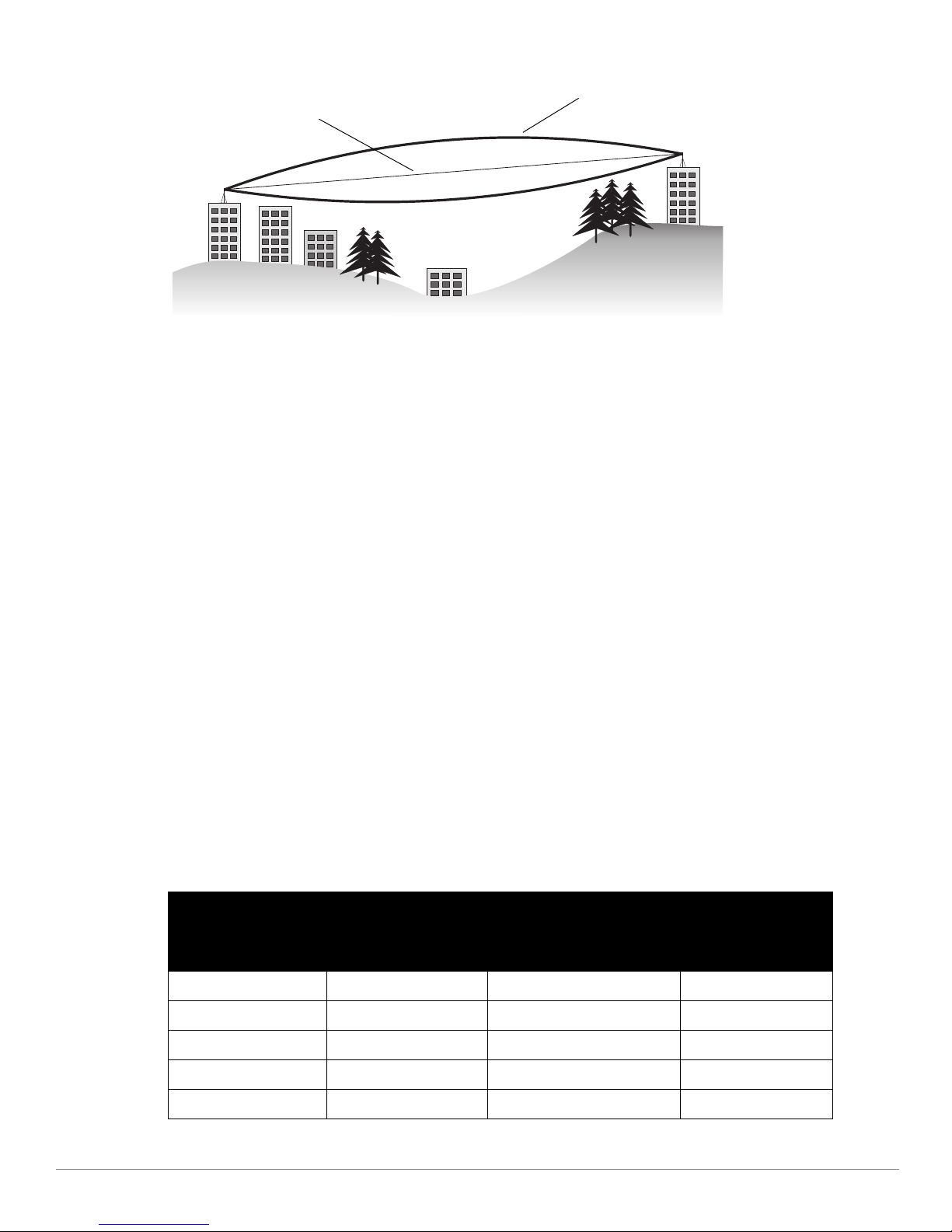
Figure 4
Radio Line of Sight
Visual Line of Sight
Line of Sight
If there are obstacles in the radio path, there may still be a radio link but the quality and strength of the signal will
be affected. Calculating the maximum clearance from objects on a path is important as it directly affects the
decision on antenna placement and height. It is especially critical for long-distance links, where the radio signal
could easily be lost.
When planning the radio path for a wireless bridge or mesh link, consider these factors:
Avoid any partial line of sight between the antennas
Be cautious of trees or other foliage that may be near the path, or may grow and obstruct the path.
Be sure there is enough clearance from buildings and that no building construction may eventually block the
path.
For very long distance links, the curvature of the earth (20 cm per km) may need to be considered in the
calculation of relative heights.
Check the topology of the land between the antennas using topographical maps, aerial photos, or even
satellite image data (software packages are available that may include this information for your area)
Avoid a path that may incur temporary blockage due to the movement of cars, trains, or aircraft.
Antenna Height
A reliable wireless bridge or mesh link is usually best achieved by mounting the antennas at each end high enough
for a clear radio line of sight between them. The minimum height required depends on the distance of the link,
obstacles that may be in the path, topology of the terrain, and the curvature of the earth (for links over 3 miles).
For long-distance links, the AP may have to be mounted on masts or poles that are tall enough to attain the
minimum required clearance. Use the following table to estimate the required minimum clearance above the
ground or path obstruction (for 5 GHz bridge links).
Table 5
Total Link Distance
0.25 mile (0.402 km) 4.6 ft (1.4 m) 0.007 ft (0.002 m) 4.6 ft (1.4 m)
0.5 mile (0.805 km) 6.2 ft (1.9 m) 0.03 ft (0.010 m) 6.2 ft (1.9 m)
1 mile (1.6 km) 8.9 ft (2.7 m) 0.13 ft (0.04 m) 8.9 ft (2.7 m)
2 miles (3.2 km) 12.5 ft (3.8 m) 0.5 ft (0.15 m) 13.1 ft (4.0 m)
3 miles (4.8 km) 15.4 ft (4.7 m) 1.0 ft (0.3 m) 16.4 ft (5.0 m)
Antenna Minimum Height and Clearance Requirements
Max Clearance for
60% of First Fresnel
Zone at 5.8 GHz
Approximate Clearance
for Earth Curvature
Total Clearance
Required at
Mid-point of Link
Dell PowerConnect W-IAP175 Outdoor Instant Access Point | Installation Guide 9
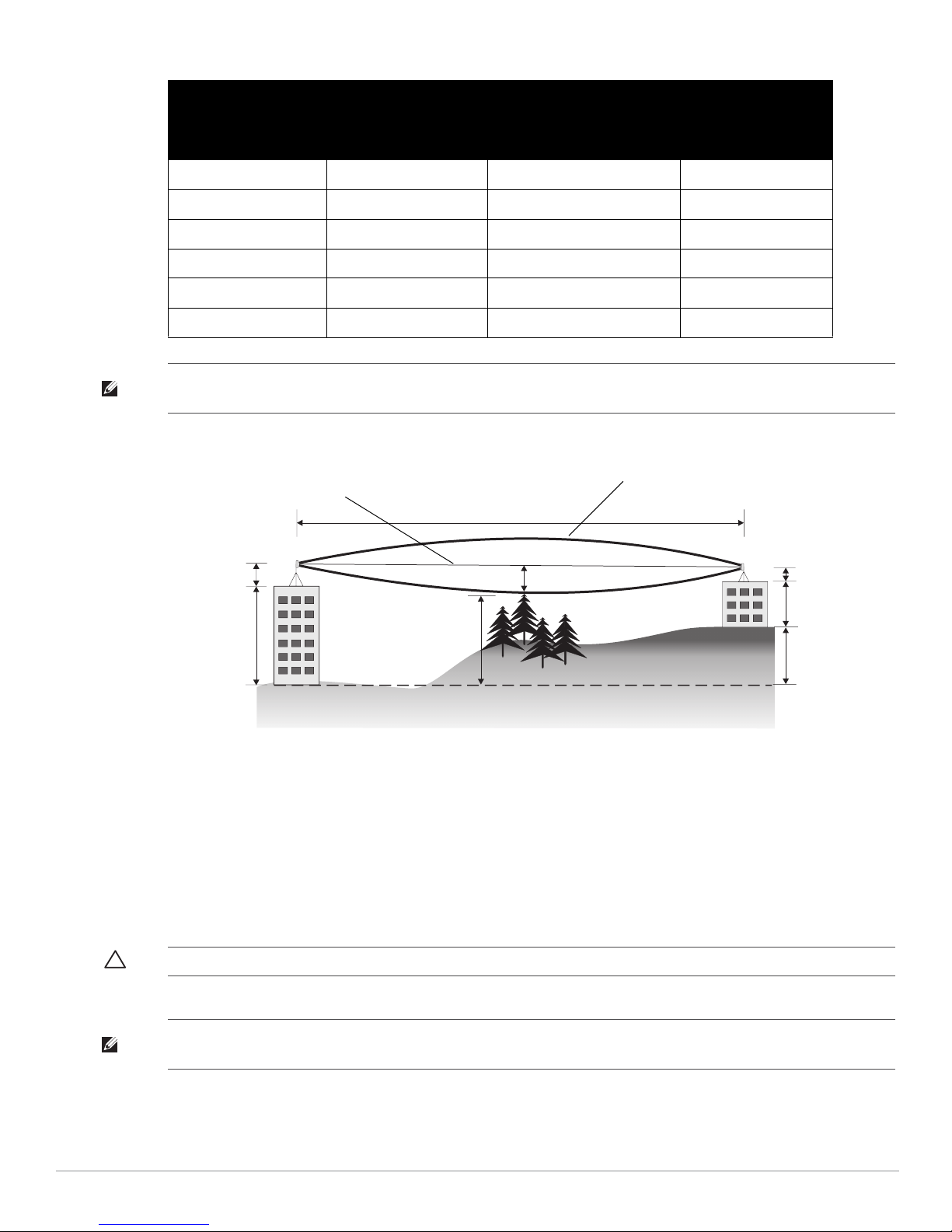
Table 5
A
B
3 miles (4.8 km)
4.7 m
17.7 m
20 m
2.4 m
12 m
9m
1.4m
Radio Line of Sight
Visual Line of Sight
Antenna Minimum Height and Clearance Requirements
Max Clearance for
Total Link Distance
60% of First Fresnel
Zone at 5.8 GHz
4 miles (6.4 km) 17.7 ft (5.4 m) 2.0 ft (0.6 m) 19.7 ft (6.0 m)
5 miles (8 km) 20 ft (6.1 m) 3.0 ft (0.9 m) 23 ft (7.0 m)
7 miles (11.3 km) 23.6 ft (7.2 m) 6.2 ft (1.9 m) 30 ft (9.1 m)
9 miles (14.5 km) 27 ft (8.2 m) 10.2 ft (3.1 m) 37 ft (11.3 m)
12 miles (19.3 km) 30.8 ft (9.4 m) 18.0 ft (5.5 m) 49 ft (14.9 m)
15 miles (24.1 km) 34.4 ft (10.5 m) 28.0 ft (8.5 m) 62.7 ft (19.1 m)
NOTE: To avoid any obstruction along the path, the height of the object must be added to the minimum clearance required for a
clear radio line of sight. Consider the following simple example, illustrated in Figure 5.
Figure 5
Antenna Height and Line of Sight
Approximate Clearance
for Earth Curvature
Total Clearance
Required at
Mid-point of Link
A wireless bridge or mesh link is deployed to connect building A to building B, which is located three miles (4.8
km) away. Mid-way between the two buildings is a small tree-covered hill. From the above table it can be seen
that for a three-mile link, the object clearance required at the mid-point is 4.7 m (15.4 ft). The tree tops on the
hill are at an elevation of 17.7 m (58.1 ft), so the antennas at each end of the link need to be at least 22.4 m (73.5
ft) high. Building A is six stories high, or 20 m (66 ft), so a 2.4 m (7.9 ft) mast or pole must be constructed on its
roof to achieve the required antenna height. Building B is only three stories high, or 9 m (30 ft), but is located at
an elevation that is 12 m (39 ft) higher than building A. To mount an antenna at the required height on building
B, a mast or pole of 1.4 m (4.6 ft) is needed.
CAUTION: Never construct a radio mast, pole, or tower near overhead power lines.
NOTE: Local regulations may limit or prevent construction of a high radio mast or tower. If your wireless bridge or mesh link
requires a high radio mast or tower, consult a professional contractor for advice.
10 Dell PowerConnect W-IAP175 Outdoor Instant Access Point | Installation Guide
 Loading...