

Page 1

Dell PowerConnect
W-AirWave 7.6
User Guide
Page 2

Copyright
© 2013 Aruba Networks, Inc. Aruba Networks trademarks include , Aruba Networks®, Aruba Wireless Networks®, the registered Aruba the Mobile Edge Company logo, and Aruba Mobility Management System®.
Dell™, the DELL™ logo, and PowerConnect™ are trademarks of Dell Inc.
All rights reserved. Specifications in this manual are subject to change without notice.
Originated in the USA. All other trademarks are the property of their respective owners.
Open Source Code
Certain Aruba products include Open Source software code developed by third parties, including software code
subject to the GNU General Public License (GPL), GNU Lesser General Public License (LGPL), or other Open
Source Licenses. Includes software from Litech Systems Design. The IF-MAP client library copyright 2011
Infoblox, Inc. All rights reserved. This product includes software developed by Lars Fenneberg, et al. The Open
Source code used can be found at this site:
http://www.arubanetworks.com/open_source
Legal Notice
The use of Aruba Networks, Inc. switching platforms and software, by all individuals or corporations, to terminate
other vendors’ VPN client devices constitutes complete acceptance of liability by that individual or corporation for
this action and indemnifies, in full, Aruba Networks, Inc. from any and all legal actions that might be taken against it
with respect to infringement of copyright on behalf of those vendors.
Jan 2013 | 0510897-12 Dell PowerConnect W-AirWave 7.6 | User Guide
Page 3

Contents
Introduction 1
A Unified Wireless Network Command Center 1
AirWave Management Platform 1
VisualRF 2
RAPIDS 2
Master Console and Failover 3
Integrating AirWave into the Network and Organizational Hierarchy 3
Administrative Roles 4
Configuring AirWave 5
Before You Begin 5
Formatting the Top Header 5
Customizing Columns in Lists 7
Resetting Pagination Records 8
Using the Pagination Widget 9
Using Export CSV for Lists and Reports 9
Defining Graph Display Preferences 10
Customizing the Dashboard 10
Adding Widgets 11
Available Widgets 11
Search Preferences 14
Setting Severe Alert Warning Behavior 15
Defining General AirWave Server Settings 16
AMP Setup > General 16
General Settings 16
Automatic Authorization Settings 17
Top Header Settings 18
Search Method 18
Home Overview Preferences 18
Display Settings 19
Device Configuration Settings 19
AMP Features 20
External Logging Settings 20
Historical Data Retention Settings 21
Firmware Upgrade Defaults 23
Additional AMP Services 23
Performance Settings 24
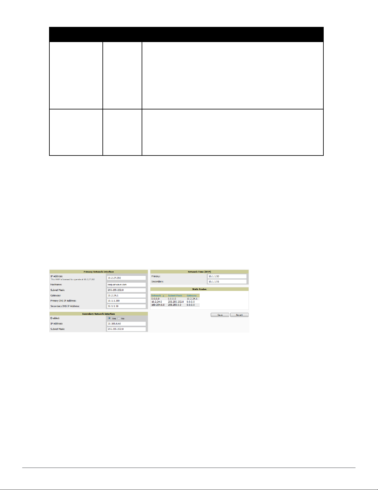
Defining AirWave Network Settings 25
Dell PowerConnect W-AirWave 7.6 | User Guide | iii
Page 4

Primary Network Interface Settings 25
Secondary Network Interface Settings 26
Network Time Protocol (NTP) Settings 26
Static Routes 27
Creating AirWave Users 27
AirWave User Roles 29
User Roles and VisualRF 29
Creating AirWave User Roles 29
Configuring Login Message, TACACS+, RADIUS, and LDAP Authentication 33
Setting Up Login Configuration Options 34
Setting Up Single Sign-On 34
Setting Up Certificate Authentication 34
Specifying the Authentication Priority 35
Configuring RADIUS Authentication and Authorization 35
Integrating a RADIUS Accounting Server 36
Configuring TACACS+ Authentication 37
Configuring Cisco ACS to Work with AirWave 38
Configuring LDAP Authentication and Authorization 39
Enabling AirWave to Manage Your Devices 40
Configuring Communication Settings for Discovered Devices 41
Loading Device Firmware Onto AirWave (optional) 43
Loading Firmware Files onto AirWave 44
Using Web Auth Bundles in AirWave 46
Setting Up Device Types 46
Configuring Cisco WLSE and WLSE Rogue Scanning 47
Introduction to Cisco WLSE 47
Initial WLSE Configuration 48
Adding an ACS Server for WLSE 48
Enabling Rogue Alerts for Cisco WLSE 48
Configuring WLSE to Communicate with APs 48
Discovering Devices 48
Managing Devices 49
Inventory Reporting 49
Defining Access 49
Grouping 49
Configuring IOS APs for WDS Participation 49
WDS Participation 49
Primary or Secondary WDS 50
Configuring ACS for WDS Authentication 50
Configuring Cisco WLSE Rogue Scanning 50
Configuring ACS Servers 52
Integrating AirWave with an Existing Network Management Solution (NMS) 53
Auditing PCI Compliance on the Network 54
Introduction to PCI Requirements 54
PCI Auditing 55
iv | Dell PowerConnec t W-AirWave 7.6 | User Guide
Page 5

Enabling or Disabling PCI Auditing 56
Deploying WMS Offload 57
Overview of WMS Offload in AirWave 57
General Configuration Tasks Supporting WMS Offload in AirWave 58
Additional Information Supporting WMS Offload 58
Configuring and Using Device Groups 59
AirWave Groups Overview 60
Viewing All Defined Device Groups 61
Configuring Basic Group Settings 62
Adding and Configuring Group AAA Servers 69
Configuring Group Security Settings 70
Configuring Group SSIDs and VLANs 74
Configuring Radio Settings for Device Groups 78
Cisco WLC Group Configuration 81
Accessing Cisco WLC Configuration 81
Navigating Cisco WLC Configuration 82
Configuring WLANs for Cisco WLC Devices 82
Defining and Configuring LWAPP APGroups for Cisco Devices 85
Viewing and Creating Cisco AP Groups 85
Configuring Cisco Controller Settings 86
Configuring Wireless Parameters for Cisco Controllers 87
Configuring Cisco WLC Security Parameters and Functions 87
Configuring Management Settings for Cisco WLC 88
Configuring Group PTMP Settings 88
Configuring Proxim Mesh Radio Settings 89
Configuring Group MAC Access Control Lists 91
Specifying Minimum Firmware Versions for APs in a Group 91
Comparing Device Groups 92
Deleting a Group 93
Changing Multiple Group Configurations 94
Modifying Multiple Devices 95
Using Global Groups for Group Configuration 98
Discovering, Adding, and Managing Devices 101
Device Discovery Overview 101
Discovering and Adding Devices 101
SNMP/HTTP Scanning 102
Adding Networks for SNMP/HTTP Scanning 102
Adding Credentials for Scanning 103
Defining a Scan Set 104
Running a Scan Set 104
The Cisco Discovery Protocol (CDP) 106
Authorizing Devices to AirWave from APs/Devices > New Page 106
Manually Adding Individual Devices 107
Adding Devices with the Device Setup > Add Page 107
Dell PowerConnect W-AirWave 7.6 | User Guide | v
Page 6

Adding Multiple Devices from a CSV File 110
Adding Universal Devices 111
Assigning Devices to the Ignored Page 112
Unignoring a Device 112
Monitoring Devices 113
Viewing Device Monitoring Statistics 113
Understanding the APs/Devices > Monitor Pages for All Device Types 114
Monitoring Data Specific to Wireless Devices 115
Evaluating Radio Statistics for an AP 120
Overview of the Radio Statistics Page 121
Viewing Real-Time ARM Statistics 121
Issues Summary section 121
802.11 Radio Counters Summary 122
Radio Statistics Interactive Graphs 122
Recent ARM Events Log 123
Detected Interfering Devices Table 124
Active BSSIDs Table 125
Monitoring Data for Mesh Devices 125
Monitoring Data for Wired Devices (Routers and Switches) 126
Understanding the APs/Devices > Interfaces Page 128
Auditing Device Configuration 129
Using Device Folders (Optional) 130
Configuring and Managing Devices 131
Moving a Device from Monitor Only to Manage Read/Write Mode 132
Configuring AP Settings 133
Setting a Maintenance Window for a Device 138
Configuring Device Interfaces for Switches 139
Individual Device Support and Firmware Upgrades 142
Troubleshooting a Newly Discovered Down Device 144
Setting up Spectrum Analysis in AirWave 146
Spectrum Configurations and Prerequisites 146
Setting up a Permanent Spectrum Dell AP Group 147
Configuring an Individual AP to run in Spectrum Mode 148
Configuring a Controller to use the Spectrum Profile 148
Creating and Using Templates 151
Group Templates 151
Supported Device Templates 151
Template Variables 152
Viewing and Adding Templates 152
Configuring General Template Files and Variables 155
Configuring General Templates 155
IOS Configuration File Template 156
Device Configuration File on APs/Devices > Audit Configuration Page 156
Using Template Syntax 157
Using AP-Specific Variables 157
vi | Dell PowerConnec t W-AirWave 7.6 | User Guide
Page 7

Using Directives to Eliminate Reporting of Configuration Mismatches 157
Ignore_and_do_not_push Command 158
Push_and_exclude Command 158
Using Conditional Variables in Templates 158
Using Substitution Variables in Templates 159
Configuring Templates for Dell PowerConnect W-Instant 160
Configuring Templates for AirMesh 161
Configuring Cisco IOS Templates 162
Applying Startup-config Files 162
WDS Settings in Templates 162
SCPRequired Settings in Templates 163
Supporting Multiple Radio Types via a Single IOS Template 163
Configuring Single and Dual-Radio APs via a Single IOS Template 164
Configuring Cisco Catalyst Switch Templates 164
Configuring Symbol Controller / HP WESM Templates 164
Configuring a Global Template 166
Using RAPIDS and Rogue Classification 169
Introduction to RAPIDS 169
Viewing Overall Network Health on RAPIDS> Overview 170
Setting Up RAPIDS 171
RAPIDS Setup 171
Basic Configuration 171
Classification Options 173
Containment Options 173
Filtering Options 173
Additional Settings 174
Defining RAPIDSRules 174
Controller Classification with WMSOffload 174
Device OUI Score 175
Rogue Device Threat Level 175
Viewing and Configuring RAPIDS Rules 176
Deleting or Editing a Rule 178
Recommended RAPIDS Rules 178
Using RAPIDS Rules with Additional AirWave Functions 179
Viewing Rogues on the RAPIDS > List Page 179
Overview of the RAPIDS > Detail Page 181
Viewing Ignored Rogue Devices 183
Using RAPIDS Workflow to Process Rogue Devices 183
Score Override 183
Using the Audit Log 184
Additional Resources 185
Performing Daily Administration in AirWave 187
Monitoring and Supporting AirWave with the System Pages 187
Using the System > Status Page 188
Dell PowerConnect W-AirWave 7.6 | User Guide | vii
Page 8

Viewing Device Events in System > Syslog & Traps 189
Using the System > Event Log Page 190
Viewing, Delivering, and Responding to Triggers and Alerts 191
Viewing Triggers 191
Creating New Triggers 191
Setting Triggers for Devices 194
Setting Triggers for Interfaces and Radios 195
Setting Triggers for Discovery 196
Setting Triggers for Clients 196
Setting Triggers for RADIUS Authentication Issues 197
Setting Triggers for IDS Events 198
Setting Triggers for AirWave Health 198
Delivering Triggered Alerts 199
Viewing Alerts 199
Responding to Alerts 200
Monitoring and Supporting WLAN Clients 201
Overview of the Clients Pages 201
Monitoring WLAN Users in the Clients > Connected and Clients > All Pages 202
Monitoring Rogue Clients With the Clients > Rogue Clients Page 205
Supporting Guest WLAN Users With the Clients > Guest Users Page 206
Supporting VPN Users with the Clients > VPN Sessions Page 208
Supporting RFID Tags With the Clients > Tags Page 209
Evaluating and Diagnosing User Status and Issues 210
Evaluating User Status with the Clients > Client Detail Page 210
Mobile Device Access Control in Clients > Client Detail and Clients > Connected 211
Classifying Dell Devices in Client Detail 212
Quick Links for Clients on Dell Devices 212
Using the Deauthenticate Client Feature 213
Viewing a Client’s Association History 213
Viewing the Rogue Association History for a Client 213
Evaluating Client Status with the Clients > Diagnostics Page 214
Managing Mobile Devices with SOTI MobiControl and AirWave 214
Overview of SOTI MobiControl 214
Prerequisites for Using MobiControl with AirWave 214
Adding a Mobile Device Management Server for MobiControl 215
Accessing MobiControl from the Clients > Client Detail Page 215
Monitoring and Supporting AirWave with the Home Pages 216
Monitoring AirWave with the Home > Overview Page 216
Viewing the RF Performance Page 218
Viewing and Updating License Information 219
The Home > Search Page 220
Accessing AirWave Documentation 222
Configuring Your Own User Information with the Home > User Info Page 222
Using the System > Configuration Change Jobs Page 225
Using the System > Firmware Upgrade Jobs Page 225
viii | Dell PowerConnect W-AirWave 7.6 | User Guide
Page 9

Using the System > Performance Page 226
Supporting AirWave Servers with the Master Console 229
Using the Public Portal on Master Console 230
Adding a Managed AMP with the Master Console 230
Using Global Groups with Master Console 231
Backing Up AirWave 232
Viewing and Downloading Backups 232
Running Backup on Demand 232
Restoring from a Backup 232
Using AirWave Failover for Backup 233
Navigation Section of AirWave Failover 233
Adding Watched AirWave Stations 233
Logging out of AirWave 234
Creating, Running, and Emailing Reports 235
Overview of AirWave Reports 235
Reports > Definitions Page Overview 235
Reports > Generated Page Overview 237
Using Daily Reports 238
Viewing Generated Reports 238
Using Custom Reports 239
Using the Dell PowerConnect W License Report 240
Using the Capacity Planning Report 240
Using the Client Session Report 242
Using the Configuration Audit Report 243
Using the Device Summary Report 244
Using the Device Uptime Report 246
Using the IDS Events Report 247
Using the Inventory Report 248
Using the Memory and CPU Utilization Report 248
Using the Network Usage Report 249
Using the New Clients Report 250
Using the New Rogue Devices Report 250
Using the PCI Compliance Report 252
Using the Port Usage Report 253
Using the RADIUS Authentication Issues Report 254
Using the RF Health Report 255
Using the Rogue Clients Report 256
Using the Rogue Containment Audit Report 257
Using the VPN Session Report 257
Defining Reports 258
Emailing and Exporting Reports 262
Emailing Reports in General Email Applications 262
Emailing Reports to Smarthost 263
Exporting Reports to XML, CSV, or PDF 263
Dell PowerConnect W-AirWave 7.6 | User Guide | ix
Page 10

Using VisualRF 265
Features 266
Useful Terms 266
Starting VisualRF 267
Basic QuickView Navigation 267
Network View Navigation 268
Overlays 268
Type section 268
Floors section 269
Frequencies section 269
Display Menu 269
Device Types section 269
Floorplan Features section 269
Relations section 269
Edit Menu 270
Mesh View Navigation 271
Using the Settings in the VisualRF > Setup Page 272
Server Settings 273
Location Settings 274
Location Calculation Timer Settings 275
Attenuation Settings 276
Adding a New Attenuation 277
VisualRF Resource Utilization 277
Configuring QuickView Personal Preferences 278
Increasing Location Accuracy 281
Adding Exterior Walls 282
Location Training for Stationary Devices 283
Adding Client Surveys 284
Adding Regions 285
Adding Location Probability Regions 285
Adding a Wiring Closet 286
Viewing Port Status on Deployed Switches 287
Fine-Tuning Location Service in VisualRF > Setup 288
Configuring Infrastructure 288
Deploying APs for Client Location Accuracy 289
Using QuickView to Assess RF Environments 290
Viewing a Wireless User’s RF Environment 290
Tracking Location History 291
Checking Signal Strength to Client Location 291
Viewing an AP’s Wireless RF Environment 292
Viewing a Floor Plan’s RF Environment 293
Viewing a Network, Campus, Building’s RF Environment 293
Viewing Campuses, Buildings, or Floors from a Tree View 294
Planning and Provisioning 294
Creating a New Campus 295
x | Del l Power Connect W-AirWave 7.6 | User Guide
Page 11

Creating a New Building in a Campus 295
Importing a Floor Plan 297
Editing a Floor Plan Image 298
Cropping the Floor Plan Image 298
Sizing a Non-CAD Floor Plan 299
Removing Color from a Floor Plan Image 299
Assigning Campus, Building and Floor Numbers 299
Assigning Optional Planner, Owner, or Installer Information for the Floor Plan 300
Controlling the Layers in the Uploaded Floor Plan (CAD only) 300
Error Checking of CAD Images 300
Last Steps in Editing an Uploaded Image 301
Provisioning Existing Access Points onto the Floor Plan 301
Automatically Provisioning APs onto a Floor Plan 302
Tweaking a Planning Region 304
Auto-Matching Planned Devices 305
Printing a Bill of Materials Report 305
Importing and Exporting in VisualRF 306
Exporting a campus 306
Importing from CAD 306
Batch Importing CAD Files 307
Requirements 307
Pre Processing Steps 307
Upload Processing Steps 307
Post Processing Steps 308
Sample Upload Instruction XML File 308
Common Importation Problems 308
Importing from a Dell PowerConnect W-Series Controller 308
Pre-Conversion Checklist 308
Process on Controller 309
Process on AirWave 309
VisualRF Location APIs 309
Sample Device Location Response 309
Sample Site Inventory Response 309
About VisualRF Plan 310
Overview 310
Minimum requirements 310
VisualRF Plan Installation 311
Differences between VisualRF and VisualRF Plan 311
Index 313
Dell PowerConnect W-AirWave 7.6 | User Guide | xi
Page 12

xii | Dell PowerConnect W-AirWave 7.6 | User Guide
Page 13

Chapter 1
Introduction
Thank you for choosing Dell PowerConnect W-AirWave. AirWave makes it easy and efficient to manage your
wireless network by combining industry-leading functionality with an intuitive user interface, enabling network
administrators and helpdesk staff to support and control even the largest wireless networks in the world.
The User Guide provides instructions for the installation, configuration, and operation of AirWave. This chapter
includes the following topics:
l "A Unified Wireless Network Command Center" on page 1
l "Integrating AirWave into the Network and Organizational Hierarchy " on page 3
If you have any questions or comments, please contact Dell support at dell.com/support.
A Unified Wireless Network Command Center
AirWave is the only network management software that offers you a single intelligent console from which to
monitor, analyze, and configure wireless networks in automatic fashion. Whether your wireless network is simple or a
large, complex, multi-vendor installation, AirWave manages it all.
AirWave supports hardware from leading wireless vendors including the following:
l Dell PowerConnect W-Series
l Aruba Networks
l Avaya
l Cisco (Aironet and WLC)
l Enterasys
l Juniper Networks
l LANCOM Systems
l Meru
l Nortel
l ProCurve by HP
l Proxim
l Symbol
l Trapeze
l Tropos
and many others.
The components of the AirWave are in the next section.
AirWave Management Platform
The AirWave Management Platform (AMP) is the centerpiece of AirWave, offering the following functions and
benefits:
Dell PowerConnect W-AirWave 7.6 | User Guide Introduction | 1
Page 14

l Core network management functionality:
n Network discovery
n Configuration of APs & controllers
n Automated compliance audits
n Firmware distribution
n Monitoring of every device and user connected to the network
n Real-time and historical trend reports
l Granular administrative access
n Role-based (for example, Administrator contrasted with Help Desk)
n Network segment (for example, Retail Store network contrasted with Corporate HQ network)
l Flexible device support
n Thin, thick, mesh network architecture
n Multi-vendor support
n Current and legacy hardware support
VisualRF
VisualRF is a powerful tool for monitoring and managing radio frequency (RF) dynamics within your wireless
network, to include the following functions and benefits:
l Accurate location information for all wireless users and devices
l Up-to-date heat maps and channel maps for RF diagnostics
n Adjusts for building materials
n Supports multiple antenna types
l Floor plan, building, and campus views
l Visual display of errors and alerts
l Easy import of existing floor plans and building maps
l Planning of new floor plans and AP placement recommendations
RAPIDS
RAPIDS is a powerful and easy-to-use tool for monitoring and managing security on your wireless network, to
include the following features and benefits:
l Automatic detection of unauthorized wireless devices
l Rogue device classification that supports multiple methods of rogue detection
l Wireless detection:
n Uses authorized wireless APs to report other devices within range.
n Calculates and displays rogue location on VisualRF map.
l Wired network detection:
n Discovers rogue APs located beyond the range of authorized APs/sensors.
n Queries routers and switches.
n Ranks devices according to the likelihood they are rogues.
n Multiple tests to eliminate false positive results.
n Provides rogue discovery that identifies the switch and port to which a rogue device is connected.
2 | Introduction Dell PowerConnect W-AirWav e 7.6 | User Guide
Page 15

Master Console and Failover
The Dell PowerConnect W-AirWave Master Console and Failover tools enable network-wide information in easy-tounderstand presentation, to entail operational information and high-availability for failover scenarios. The benefits of
these tools include the following:
l Provides network-wide visibility, even when the WLAN grows to 50,000+ devices
l Executive Portal allows executives to view high-level usage and performance data
l Aggregated alerts
l Failover
n Many-to-one failover
n One-to-one failover
The Master Console and Failover servers can be configured with a Device Down trigger that generates an alert if
communication is lost. In addition to generating an alert, the Master Console or Failover server can also send email
or NMS notifications about the event.
Integrating AirWave into the Network and Organizational Hierarchy
Dell PowerConnect W-AirWave generally resides in the NOC and communicates with various components of your
WLAN infrastructure. In basic deployments, AirWave communicates solely with indoor wireless access points (and
WLAN controllers over the wired network. In more complex deployments, AirWave seamlessly integrates and
communicates with authentication servers, accounting servers, TACACS+ servers, LDAP servers, routers, switches,
network management servers, wireless IDS solutions, helpdesk systems, indoor wireless access points, mesh devices.
AirWave has the flexibility to manage devices on local networks, remote networks, and networks using Network
Address Translation (NAT). AirWave communicates over-the-air or over-the-wire using a variety of protocols.
The power, performance, and usability of AirWave become more apparent when considering the diverse components
within a WLAN. Table 1 itemizes some example network components.
Table 1:
Components of a WLAN
Component Description
Autonomous AP Standalone device which performs radio and authentication functions
Thin AP Radio-only device coupled with WLAN controller to perform authentication
WLAN controller Used in conjunction with thin APs to coordinate authentication and roaming
NMS Network Management Systems and Event Correlation (OpenView, Tivoli, and so forth)
RADIUS Authentication RADIUS authentication servers (Funk, FreeRADIUS, ACS, or IAS)
RADIUS Accounting AirWave itself serves as a RADIUS accounting client
Wireless Gateways Provide HTML redirect and/or wireless VPNs
TACACS+ and LDAP Used to authenticate AirWave administrative users
Routers/Switches Provide AirWave with data for user information and AP and Rogue discovery
Help Desk Systems Remedy EPICOR
Rogue APs Unauthorized APs not registered in the AirWave database of managed APs
Dell PowerConnect W-AirWave 7.6 | User Guide Introduction | 3
Page 16

Administrative Roles
The flexibility of AirWave enables it to integrate seamlessly into your business hierarchy as well as your network
topology. AirWave facilitates various administrative roles to match each individual user's role and responsibility:
l A Help Desk user may be given read-only access to monitoring data without being permitted to make
configuration changes.
l A U.S.-based network engineer may be given read-write access to manage device configurations in North America,
but not to control devices in the rest of the world.
l A security auditor may be given read-write access to configure security policies across the entire WLAN.
l NOC personnel may be given read-only access to monitoring all devices from the Master Console.
4 | Introduction Dell PowerConnect W-AirWav e 7.6 | User Guide
Page 17

Chapter 2
Configuring AirWave
This section contains the following procedures to deploy initial AirWave configuration:
l "Formatting the Top Header" on page 5
l "Customizing Columns in Lists" on page 7
l "Resetting Pagination Records" on page 8
l "Using the Pagination Widget" on page 9
l "Using Export CSV for Lists and Reports" on page 9
l "Defining Graph Display Preferences" on page 10
l "Customizing the Dashboard" on page 10
l "Setting Severe Alert Warning Behavior" on page 15
l "Defining General AirWave Server Settings" on page 16
l "Defining AirWave Network Settings" on page 25
l "Creating AirWave User Roles" on page 29
l "Creating AirWave Users" on page 27
l "Configuring Login Message, TACACS+, RADIUS, and LDAP Authentication" on page 33
l "Enabling AirWave to Manage Your Devices" on page 40
l "Setting Up Device Types" on page 46
l "Configuring Cisco WLSE and WLSE Rogue Scanning" on page 47
l "Configuring ACS Servers " on page 52
l "Integrating AirWave with an Existing Network Management Solution (NMS) " on page 53
l "Auditing PCI Compliance on the Network" on page 54
l "Deploying WMS Offload" on page 57
NOTE: Additional configurations are available after basic configuration is complete.
Before You Begin
Remember to complete the required configurations in this chapter before proceeding. AirWave support remains
available to you for any phase of AirWave installation.
Formatting the Top Header
The Dell PowerConnect W-AirWave interface centers around a horizontal row of tabs with nested subtabs.
A row of statistics hyperlinks called Top Header Stats above the tabs represents commonly used subtabs. These
hyperlinks provide the ability to view certain key statistics by mousing over, such as number and type of Down
Dell PowerConnect W-AirWave 7.6 | User Guide ConfiguringAirWave | 5
Page 18
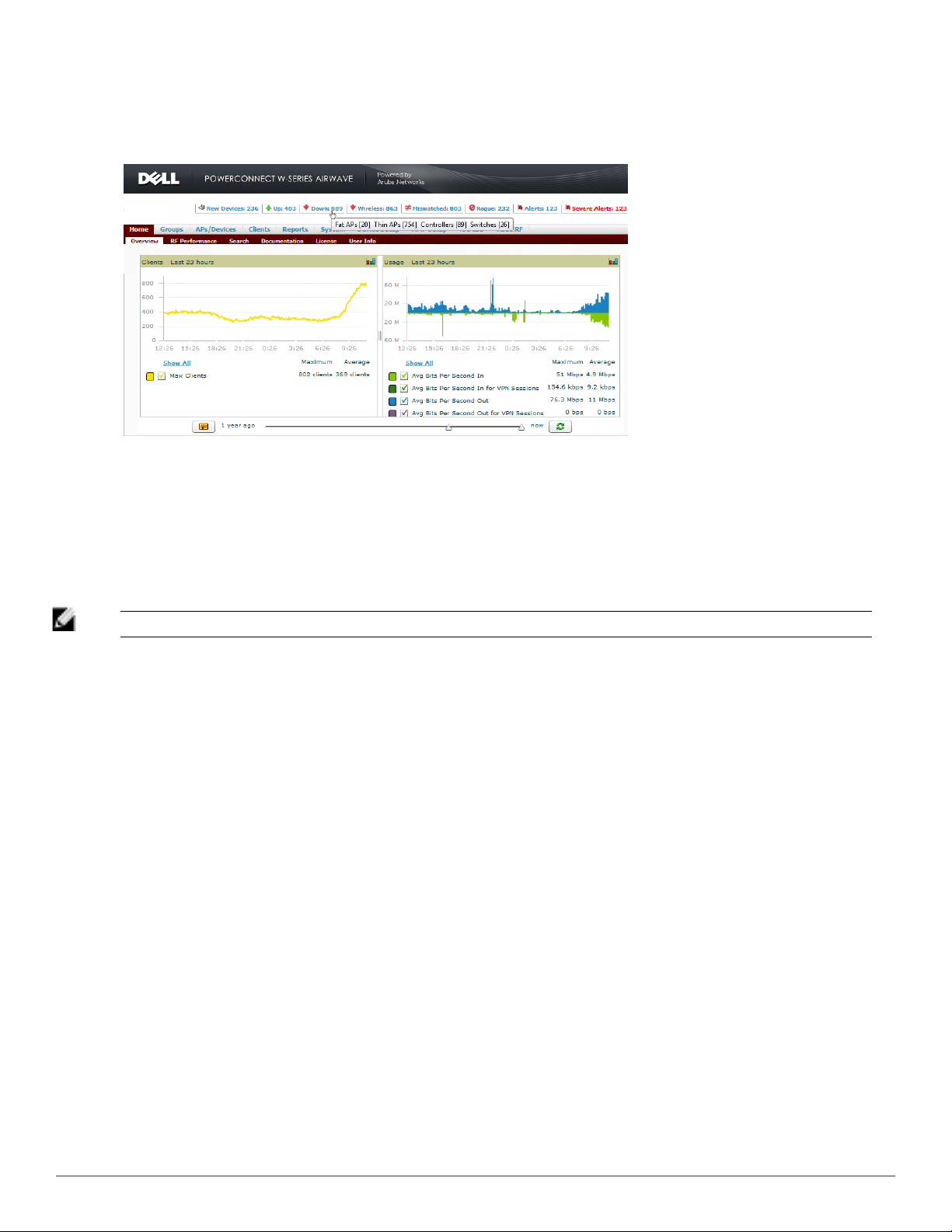
devices, and serve as shortcuts to frequently viewed subtabs. Figure 1 illustrates the navigation bar. More information
on hyperlinks, tabs, and subtabs is a available in the
Dell PowerConnect W-AirWave 7.6 Installation Guide
.
Figure 1: Navigation Bar Displaying Down Device Statistics
You can control the Top Header Stats links that appear from the AMP Setup > General page, as described in
"Defining General AirWave Server Settings" on page 16. Top Header Stats can also be customized for individual
users on the Home > User Info page. There you can select the statistics to display for certain device types and
override the AMP Setup page.
All possible display options for users are shown in Figure 2, and these fields are described in detail in "Configuring
Your Own User Information with the Home > User Info Page" on page 222.
NOTE: A confirmation message does not appear when you make modifications to the Top Header Stats.
6 | Configuring AirWave Dell PowerConnect W-AirWave 7.6 | User Guide
Page 19
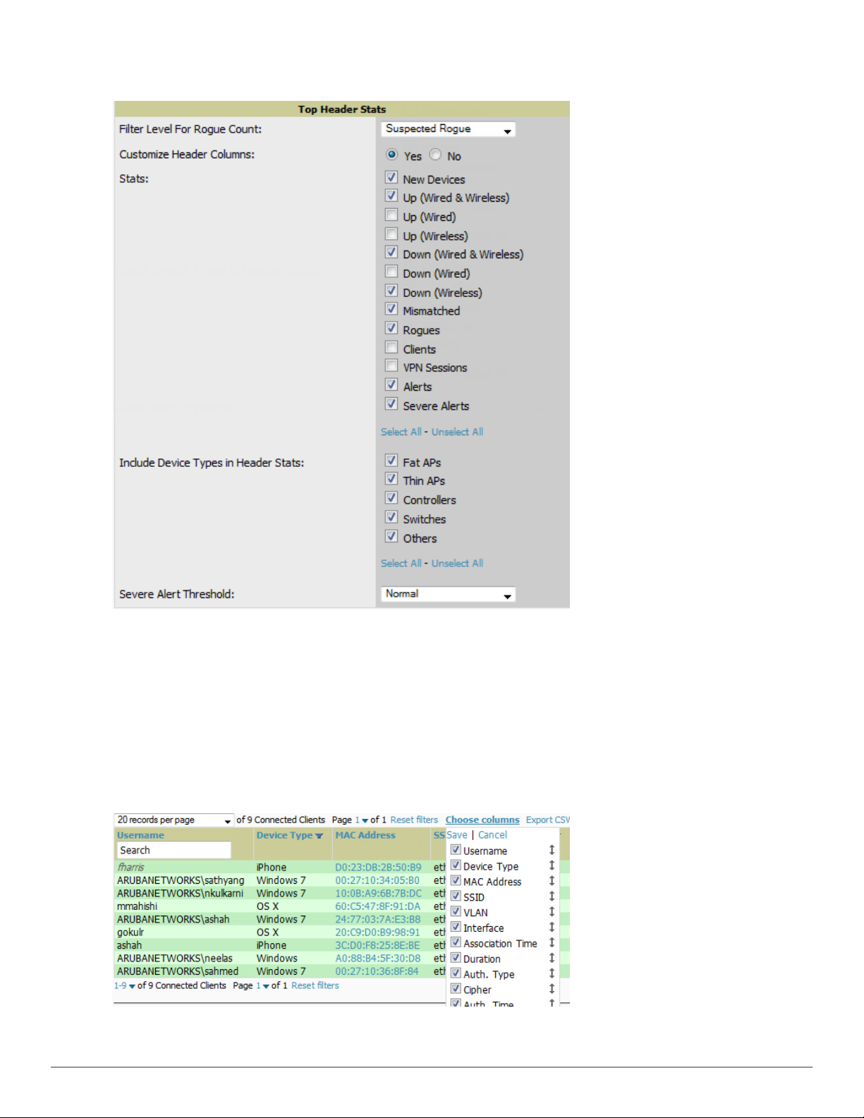
Figure 2: Home > User Info Top Header Stats Display Options
You can also set the severity level of critical alerts displayed for a user role. For details including a description of
what constitutes a severe alert, see "Setting Severe Alert Warning Behavior" on page 15.
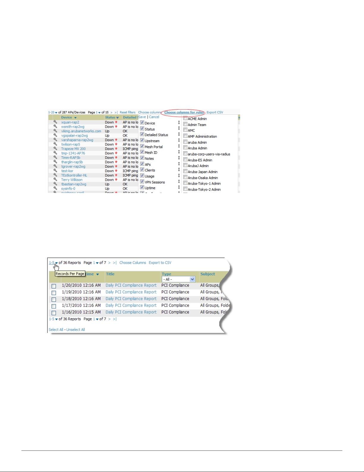
Customizing Columns in Lists
Customize the columns for any list table selecting Choose Columns, as shown in the figure below. Use the up/down
arrows to change the order in which the column heads appear.
Figure 3: Choose Columns Drop down List
Dell PowerConnect W-AirWave 7.6 | User Guide ConfiguringAirWave | 7
Page 20
More information about the universal list elements is available in Common List Settings in the
W-AirWave 7.6 Installation Guide
You can also control which column heads appear for each user role. Navigate to the Home > User Info page, and
then select Yes in the Customize Columns for Other Roles field. This exposes the Choose Columns for Roles drop
down menu in all tables shown in Figure 4.
The first column shows the user roles that were customized, if any. The second column allows you to establish leftto-right columns and order them using the arrows.
.
Dell PowerConnect
Figure 4: Table with Choose Columns for Roles Menu Selected
Resetting Pagination Records
To control the number of records in any individual list, select the link with Records Per Page mouseover text at the
top left of the table, as shown in Figure 5. AirWave remembers each list’s pagination preferences.
Figure 5: Records Per Page Drop Down Menu
To reset all Records Per Page preferences, click the Reset reset button in the Display Preferences section of the
Home > User Info page, as shown in Figure 6.
8 | Configuring AirWave Dell PowerConnect W-AirWave 7.6 | User Guide
Page 21
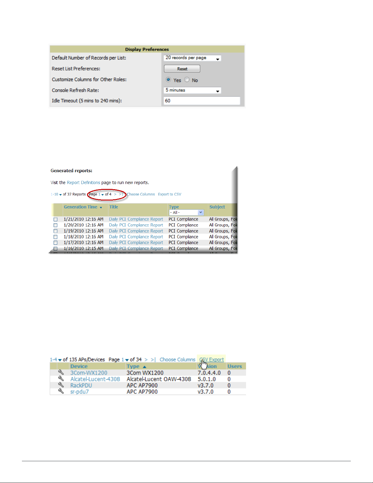
Figure 6: Home > User Info > Display Preferences section
Using the Pagination Widget
The pagination widget is located at the top and bottom of every list table, as shown in Figure 7.
Figure 7: Pagination Widget
Use the down arrow next to Page 1 to see all the page numbers for that table in a drop down menu. From here, you
can jump to any portion of the table. Select the > symbol to jump to the next page, and >| to jump to the last
page.
Using Export CSV for Lists and Reports
Some tables have a Export CSV setting you can use export the data as a spreadsheet. See Figure 8 for an example of
a list with the Export CSV option selected.
Figure 8: List with CSV Export Selected
AirWave also enables CSV exporting of all report types. For more information, see "Exporting Reports to XML, CSV,
or PDF" on page 263.
Dell PowerConnect W-AirWave 7.6 | User Guide Configuring AirWave | 9
Page 22
Defining Graph Display Preferences
Many of the graphs in AirWave are Flash-based, which allows you to adjust the graph settings attributes as shown in
Figure 9.
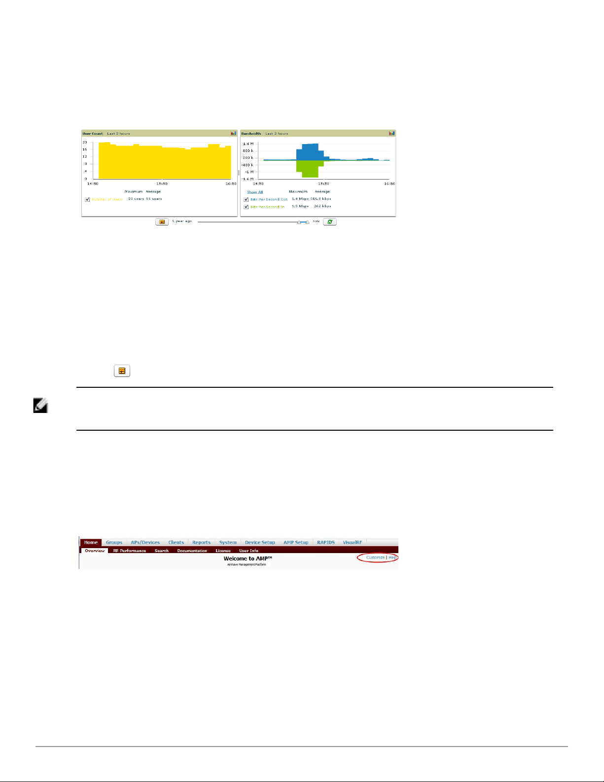
Figure 9: Interactive Graphs on the Home > Overview Page
This Flash-enabled GUI allows for custom settings and adjustments as follows:
l Drag the slider at the bottom of the screen to move the scope of the graph between one year ago and the current
time.
l Drag the slider between graphs to change the relative sizes of each.
l Deselect checkboxes to change the data displayed on each graph. The button with green arrows refreshes data on
the graph.
The Show All link displays all of the available checkboxes supporting the Flash graphs. Once a change to the slider
bars has been made, the same change can be applied to all other Flash graphs on that page with a Set time range
button ( ).
NOTE: A non-Flash version of the AirWave user page is available if desired. Instead of Flash, it uses the RRD graphs that were used in
earlier versions of AirWave. For non-Flash graphs, select the graph to open a popup window that shows historical data. Contact Dell
support for more information on activating this feature in the AirWave database.
Customizing the Dashboard
You can rearrange or remove widgets appearing on the Home > Overview dashboard by selecting the Customize link
to the right of this window, as shown in Figure 10.
Figure 10: Customize Button on the Home > Overview Page
The Customize workspace that appears is shown in Figure 11.
10 | Configuring AirWave Dell PowerConnec t W-Air Wave 7.6 | User Guide
Page 23
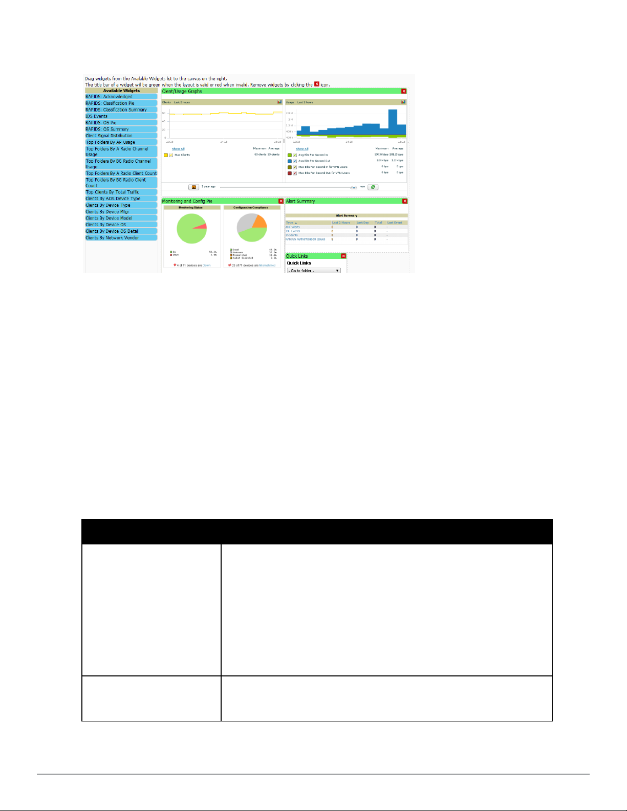
Figure 11: Customize Overview Page
Adding Widgets
The Available Widgets section on the left holds all available graphical elements (widgets). Select any blue widget tile
with a verbal description enclosed, and it immediately turns into a graphical element with a description.
Drag the widgets you want to appear on the Home > Overview dashboard across to the gridlines and arrange them
in the right section, within the gridlines. A widget snaps back to the nearest available gridline if you drop it across
two or more lines and turns red if you attempt to place it over gridlines already occupied by widgets. Widgets with a
green top banner are properly placed and set to appear when you select Save. Widgets that remain in the left section
will not appear; although they can be reinstated by selecting Restore Defaults.
Available Widgets
Table 2 describes the list of available widgets along with a description for each. Note that when a widget is enabled,
the information that displays can vary based on the user’s permission level. Certain roles, for example, limit the top
folder that a user can view.
Table 2:
Available Widgets
Widget Description
The Client graph is enabled by default and, by default, shows the maximum number of
attached clients over the last two hours. Select the Show All link to view more
specific client information on the graph, such as the total and average clients for a
specific SSID, the maximum VPN sessions, etc. The available check boxes within this
graph are determined by the SSIDs that AirWave is aware of from polling the device.
Client/Usage Graphs
The Usage graph is enabled by default and, by default, shows the average bits-persecond in/out information and average VPN in/out information. Select the Show All
link to view usage information for specific SSIDs. The available checkboxes within
this graph are determined by by the SSIDs that AirWave is aware of from polling the
device.
The information in these graphs is color coded to match the selected check boxes.
The Monitoring Status pie shows the percentage of total devices that are up and the
Monitoring and Config Pie
Dell PowerConnect W-AirWave 7.6 | User Guide Configuring AirWave | 11
number and perctentage of devices that are currently down. Clicking within this pie
chart takes you to the APs/Devices > Down page.
Page 24

Widget Description
The Configuration Compliance pie shows the percentage of devices that are
mismatched, good, unknown, and those with auditing disabled. It also provides a
summary of the total number of devices that are mismatched. Clicking within this pie
chart takes you to the APs/Devices > Mismatch page.
These pie charts are enabled by default.
The Alert Summary table is enabeld by default and provides the number of AirWave
alerts, IDS events, and RADIUS authentication issues over the last 2 hours, the last 24
hours, and the total since the last AirWave reboot.
l Click on AirWave Alerts to drill down to more detailed alert information. This
information displays in the current page. You can return to the Alert Summary
Alert Summary
graph by selecting the Home Overview link.
l Click on IDS Events to drill to more detailed event information. This link takes you
to the RAPIDS > IDS Events page.
l Click on RADIUS Authentication Issues to drill to more detailed RADIUS
authentication information. This information displays in the current page. You can
return to the Alert Summary graph by selecting the Home Overview link.
Quick Links
RAPIDS: Acknowledged
RAPIDS: Classification Pie
RAPIDS: Classification Summary
IDS Events
The Quick Links section is enabled by default. This section provides the user with easy
navigation to a specific folder, group, report, or common task.
The Acknowledged RAPIDS Devices pie chart shows the percentage of
acknowledged and unacknowledged RAPIDS that the user has visibility into. The
RAPIDS information appears from the moment a rogue is discovered until it is
deleted. Ignored rogues, however, are not included in this chart.
This chart also displays on the RAPIDS > Overview page.
The RAPIDS: Classification Pie shows the percentage of devices classified as Valid,
Suspected Neighbor, Suspected Valid, Suspected Rogue, Rogue, and Neighbor that
are attached to AirWave. The RAPIDS information appears from the moment a rogue
is discovered until it is deleted. Ignored rogues, however, are not included in this
chart.
This pie chart can also be viewed on the RAPIDS > Overview page.
The RAPIDS: Classification Summary table shows the number of devices classified as
Valid, Suspected Valid, Neighbor, Suspected Neighbor, Suspected Rogue, Rogue,
and Unclassified that are attached to AirWave. In addition, contained rogue
information will appear if Manage rogue AP containment is set to Yes on the RAPIDS
> Setup page.
The RAPIDS information appears from the moment a rogue is discovered until it is
deleted. Note that ignored rogues are not included in this chart.
This table can also be viewed on the RAPIDS > Overview page.
The IDS Events table shows the number and type of attacks logged by the intrusion
detection system over the last 2 hours, the last 24 hours, and the total since the last
AirWave reboot. This is the same table that displays on the RAPIDS > Overview page.
The RAPIDS: OS Pie chart shows the top 9 rogue devices by OS, Others, Unknown,
RAPIDS: OS Pie
and Not Scanned. The RAPIDS information appears from the moment a rogue is
discovered until it is deleted. Note that ignored rogues are not included in this chart.
This pie chart can also be viewed on the RAPIDS > Overview page.
The RAPIDS: OS Summary table shows the top 9 rogue devices by OS, Others,
Unknown, and Not Scanned. The RAPIDS information appears from the moment a
RAPIDS: OS Summary
rogue is discovered until it is deleted. Note that ignored rogues are not included in
this chart.
This table can also be viewed on the RAPIDS > Overview page.
12 | Configuring AirWave Dell PowerConnec t W-Air Wave 7.6 | User Guide
Page 25

Widget Description
This chart lists the folders and the number of APs in each folder whose usage is
greater than the cutoff (or usage threshold). The cutoff represents 75% of the
Top Folders By AP Usage
Top Folders By A Radio Channel
Usage
Top Folders By BG Radio Channel
Usage
Top Folders By A Radio Client
Count
maximum usage, where the maximum usage is the AP with the highest usage
regardless of the folder in which it resides. The cutoff value is displayed within the
title, and this value can vary. The chart takes into account approved APs with radios
based on the last 24 hours. In addition, this chart is updated every hour.
This chart shows the folders and the number of A radios (5GHz) in each folder whose
channel usage is greater than the cutoff (or usage threshold) as measured by Mbps.
This cutoff is on the on the AMP Setup > General page using the Configure Channel
Busy Threshold option. If this option is not configured, then the cutoff is 75% of the
‘maximum,’ where the ‘maximum’ refers to the AP that has the highest usage
regardless of the folder in which it resides. The cutoff value is displayed within the
title, and this value can vary. This chart takes into account approved APs with ‘A’
radios based on the last 24 hours. In addition, this chart is updated every hour.
This chart shows the folders and the number of BG radios (2.4GHz) in each folder
whose channel usage is greater than the cutoff (or usage threshold) as measured by
Mbps. This cutoff is on the on the AMP Setup > General page using the Configure
Channel Busy Threshold option. If this option is not configured, then the cutoff is 75%
of the ‘maximum,’ where the ‘maximum’ refers to the AP that has the highest usage
regardless of the folder in which it resides. The cutoff value is displayed within the
title, and this value can vary. This chart takes into account approved APs with ‘BG’
radios based on the last 24 hours. In addition, this chart is updated every hour.
This chart shows the folders and the number of A radios (5GHz) in each folder whose
client count is greater than the cutoff. The cutoff represents 75% of the ‘maximum,’
where the ‘maximum’ is the radio that has the highest client count regardless of the
folder. The cutoff value is displayed within the title and can vary. This chart takes into
account approved APs with A radios based on the last 24 hours. In addition, this chart
is updated every hour.
Top Folders By BG Radio Client
Count
Top Clients By Total Traffic
Clients By AOS Device Type
Clients By Device Type
Clients By Device Mfgr
Clients By Device Model
This chart shows the folders and the number of BG radios (2.4GHz) in each folder
whose client count is greater than the cutoff. The cutoff represents 75% of the
‘maximum,’ where the ‘maximum’ is the radio that has the highest client count
regardless of the folder. The cutoff value is displayed within the title and can vary.
This chart takes into account approved APs with BG radios based on the last 24 hours.
In addition, this chart is updated every hour.
The widget looks at currently connected clients as well has client historical
information over the past 24 hours and then displays the top 10 clients with the must
usage. You can click on a MAC address to view more information about any of the
clients that display on this table. This table is updated every hour.
This pie chart shows the percentage of clients that have attached to AirWave over the
last 24 hours based on the AOS device type.
This pie chart shows the percentage of clients that have attached to AirWave over the
last 24 hours based on the device type (such as a specific operating system or smart
phone type).
This pie chart shows the percentage of clients that have attached to AirWave over the
last 24 hours based on the client manufacturer.
This pie chart shows the percentage of clients that have attached to AirWave over the
last 24 hours based on the device model (such as the smart phone type).
Dell PowerConnect W-AirWave 7.6 | User Guide Configuring AirWave | 13
Page 26
Widget Description
Clients By Mfgr & Model
Clients By Device OS
Clients By Device OS Detail
Clients By Network Vendor
Client Signal Distribution
This pie chart shows the percentage of clients that have attached to AirWave over the
last 24 hours based on the client manufacturer and model.
This pie chart shows the percentage of clients that have attached to AirWave over the
last 24 hours based on the device operating system (such as Windows or Android).
This pie chart shows the percentage of clients that have attached to AirWave over the
last 24 hours based on the device operating system version (such as Windows NT 6.1).
This pie chart shows the percentage of clients that have attached to AirWave over the
last 24 hours based on each device’s network interface vendor.
The Client Signal Distribution chart shows the number of attached devices that have a
signal quality within a set of ranges.
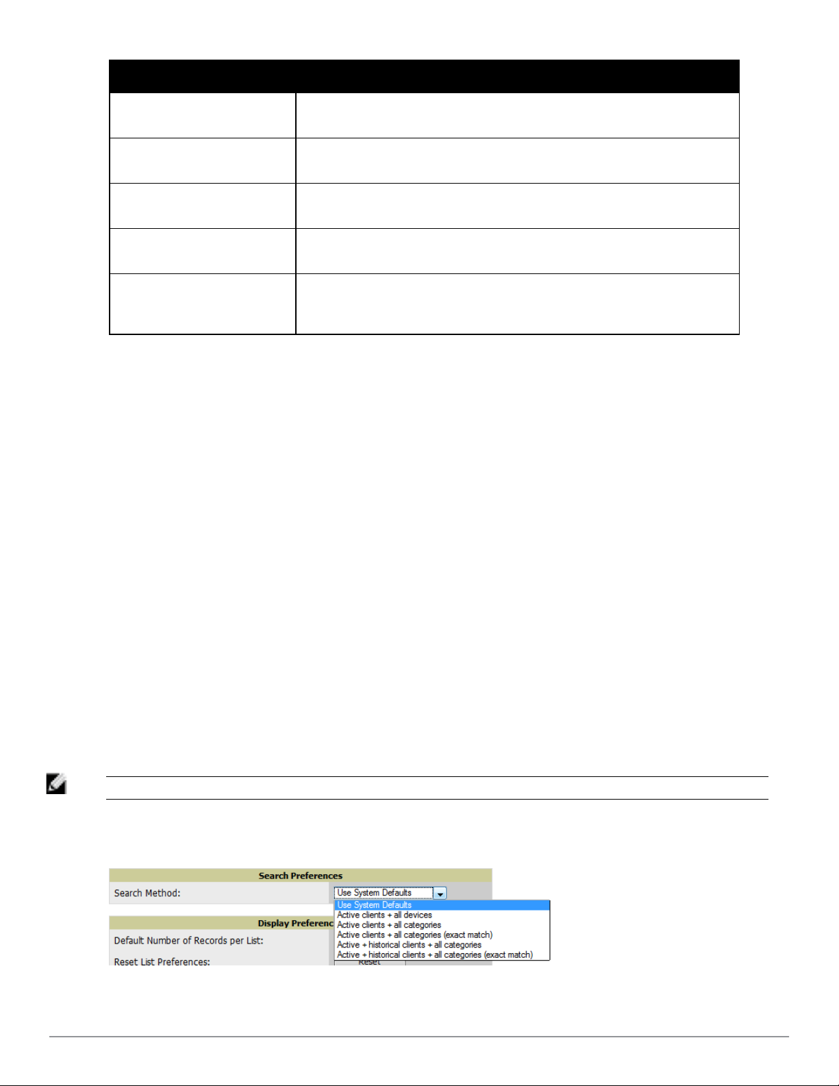
Search Preferences
For each user, you can customize the search results to display only desired categories of matches on the Home >
User Info page. Go to the Search Preferences section and select the desired search type from the Search Method
drop down. This search type will be used when a user types an entry in the Search field and then clicks Enter without
selecting a specific search type.
l Use System Defaults: The Search Method will be based on the system-wide configuration setting. This method is
configured on the AMP Setup > General page.
l Active clients + all devices: This looks at all active clients (not historical) and all devices. This search is not case-
sensitive.
l Active clients + all categories: This looks at all active clients (not historical) and all categories. This search is not
case-sensitive.
l Active clients + all categories (exact match): This looks at all active clients (not historical) and all categories.
This search returns only matches that are exactly as typed (IP, username, device name, etc). This search is casesensitive for all searched fields.
l Active + historical clients + all categories: This looks at all active and historical clients and all categories. This
search is not case-sensitive.
l Active + historical clients + all categories (exact match): This looks at all active and historical clients and all
categories. This search returns only matches that are exactly as typed (IP, username, device name, etc). This
search is case-sensitive for all searched fields.
NOTE: A confirmation message does not appear after you make modifications to Search Preferences.
Figure 12: Home > User Info Search Preferences
14 | Configuring AirWave Dell PowerConnec t W-Air Wave 7.6 | User Guide
Page 27
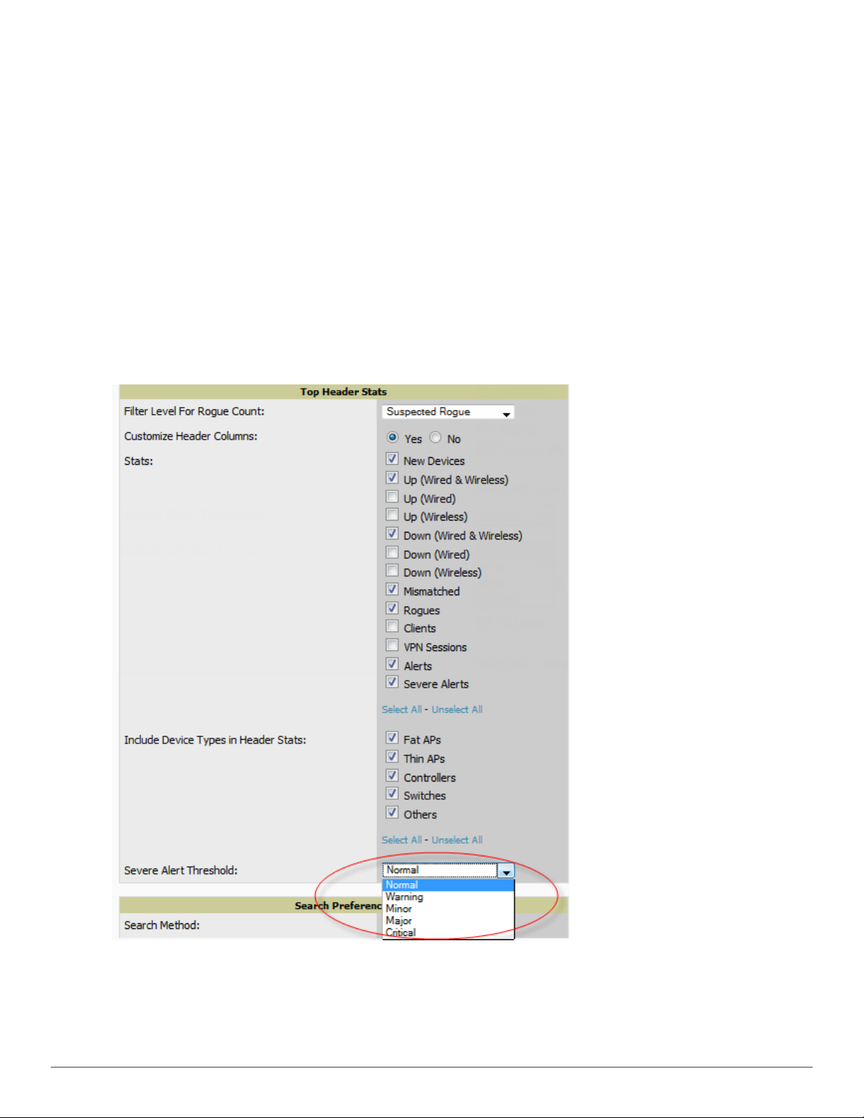
Setting Severe Alert Warning Behavior
You can control the alert levels you can see on the Alerts top header stats link from the Home > User Info page.
The Severe Alert Threshold determines the severity level that results in a Severe Alert. Specify either Normal,
Warning, Minor, Major, or Critical as the severity alert threshold value. These threshold values are tied to triggers
that are created on the System > Triggers page. For example, if a trigger is defined to result in a Critical alert, and if
the Severe Alert Threshold here is defined as Major, then the list of Severe Alerts will include all Major and Critical
alerts. Similarly, if this value is set to Normal, which is the lowest threshold, then the list of Severe Alerts will include
all alerts.
When a Severe Alert exists, a new component named Severe Alerts will appear at the right of the Status field in bold
red font. This field is hidden if there are no Severe Alerts. In addition, only users who are enabled for viewing Severe
Alerts on the Home > User Info page can see severe alerts.
The Severe Alert Threshold drop down menu, located in the Top Header Stats section of the Home > User Info
page is shown in Figure 13.
Figure 13: Home > User Info > Severe Alert Threshold Drop Down Menu
Dell PowerConnect W-AirWave 7.6 | User Guide Configuring AirWave | 15
Page 28
Defining General AirWave Server Settings
This section describes all pages accessed from the AMP Setup tab. It also describes two pages in the Device Setup
tab: the Communication and Upload Files pages. After required and optional configuration tasks in this chapter are
complete, continue to later chapters in this document to create and deploy device groups and device configuration
and discovery on the network.
Refer to the following topics for configuration information:
l "AMP Setup > General" on page 16
l "Defining AirWave Network Settings" on page 25
l "AirWave User Roles" on page 29
l "Creating AirWave Users" on page 27
l "Configuring Login Message, TACACS+, RADIUS, and LDAP Authentication" on page 33
l "Enabling AirWave to Manage Your Devices" on page 40
l "Setting Up Device Types" on page 46
AMP Setup > General
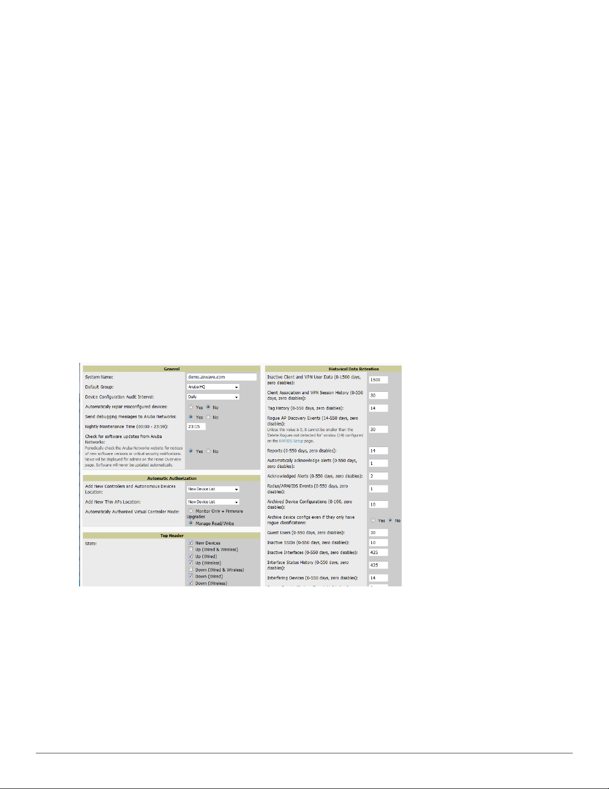
The first step in configuring AirWave is to specify the general settings for the AirWave server. Figure 14 illustrates
the AMP Setup > General page. Select Save when the General Server settings are complete and whenever making
subsequent changes. These settings are applied globally across the product (for all users).
Figure 14: AMP Setup > General Page Illustration (Partial View)
General Settings
Browse to the AMP Setup > General page, locate the General section, and enter the information described in
Table 3:
16 | Configuring AirWave Dell PowerConnec t W-Air Wave 7.6 | User Guide
Page 29

Table 3:
AMP Setup > General > General Section Fields and Default Values
Setting Default Description
System Name
Default Group
Device
Configuration Audit
Interval
Automatically repair
misconfigured
devices
Send debugging
messages
Nightly
Maintenance Time
(00:00 - 23:59)
Access
Points
Daily
Disabled
Enabled
04:15
Defines your name for your AirWave server, with a maximum limit of 20
alphanumeric characters.
Sets the device group that this AirWave server uses as the default for devicelevel configuration. Select a device group from the drop-down menu. A group
must first be defined on the Groups > List page to appear in this drop-down
menu. For additional information, refer to. "Configuring and Using Device
Groups" on page 59.
This setting defines the interval of queries which compares actual device
settings to the Group configuration policies stored in the AirWave database. If
the settings do not match, the AP is flagged as mismatched and AirWave sends
an alert via email, log, or SNMP.
NOTE: Enabling this feature with a frequency of Daily or more frequently is
recommended to ensure that your AP configurations comply with your
established policies. Specifying Never is not recommended.
If enabled, this setting automatically reconfigures the settings on the device
when the device is in Manage mode and AirWave detects a variance between
actual device settings and the Group configuration policy in the AirWave
database.
If enabled, AirWave automatically emails any system errors to Dell support at
dell.com/support to assist in debugging.
Specifies the local time of day AirWave should perform daily maintenance.
During maintenance, AirWave cleans the database, performs backups, and
completes a few other housekeeping tasks. Such processes should not be
performed during peak hours of demand.
Enables AirWave to check automatically for multiple update types. Check daily
Check for software
updates
Yes
for AirWave updates, to include enhancements, device template files, important
security updates, and other important news. This setting requires a direct
Internet connection via AirWave.
Automatic Authorization Settings
On the AMP Setup > General page, locate the Automatic Authorization section. These settings allow you to
control the conditions by which devices are automatically authorized into AP groups and folders. AirWave validates
the Folder and Group to ensure that both settings have been set to valid drop down options. Table 4 describes the
settings and default values in this section.
Table 4:
AMP Setup > General > Automatic Authorization Fields and Default Values
Setting Default Description
Globally add new controllers and autonomous devices to:
l The New Device List (located in APs/Devices > New).
l The same folder and group as the discovering device.
Add New Controllers
and Autonomous
Devices Location
New Device List
l The same group and folder of their closest IP neighbor on the same
subnet.
l Choose a group and folder. If you select this option, enter the
folder/group in the Auto Authorization Group and Auto Authorization
Folder fields that display.
NOTE: This setting can be overridden in Groups > Basic.
Dell PowerConnect W-AirWave 7.6 | User Guide Configuring AirWave | 17
Page 30

Setting Default Description
Globally add new thin APs to:
l The New Devices list.
l The same folder and group as the discovering device.
Add New Thin APs
Location
New Device List
l The same group and folder of their closest IP neighbor on the same
subnet.
l Choose a group and folder. If you select this option, enter the
folder/group in the Auto Authorization Group and Auto Authorization
Folder fields that display.
NOTE: This setting can be overridden in Groups > Basic.
Automatically
Authorized Virtual
Controller Mode
Manage
Read/Write
Specify whether Virtual Controller mode for Instant APs will be in Manage
Read/Write mode or Monitor Only mode.
Top Header Settings
On the AMP Setup > General page, locate the Top Header section to select the Top Header Stats to be displayed
at the top of the interface.
Search Method
On the AMP Setup > General page, locate the Search Method section. Select one of the following drop down
options as the system-wide default search method. This default search type will be used when a user types an entry
in the Search field and then clicks Enter without selecting a specific search type.
l Active clients + all devices: This looks at all active clients (not historical) and all devices. This search is not case-
sensitive.
l Active clients + all categories: This looks at all active clients (not historical) and all categories. This search is not
case-sensitive.
l Active clients + all categories (exact match): This looks at all active clients (not historical) and all categories.
This search returns only matches that are exactly as typed (IP, username, device name, etc). This search is casesensitive for all searched fields.
l Active + historical clients + all categories: This looks at all active and historical clients and all categories. This
search is not case-sensitive.
l Active + historical clients + all categories (exact match): This looks at all active and historical clients and all
categories. This search returns only matches that are exactly as typed (IP, username, device name, etc). This
search is case-sensitive for all searched fields.
Per-user search preferences can be set in the Home > User Info page; refer to "Search Preferences" on page 14.
Home Overview Preferences
On the AMP Setup > General page, locate the Home Overview Preferences section. Table 5 describes the settings
and default values in this section.
Table 5:
18 | Configuring AirWave Dell PowerConnec t W-Air Wave 7.6 | User Guide
AMP Setup > General > Home Overview Preferences Fields and Default Values
Setting Default Description
Configure Channel
Busy Threshold
Channel Busy
Threshold (%)
Yes
n/a
Whether you want to configure the threshold at which a channel is considered to
be busy at the Top Folders By Radio Channel Usage Overview widget.
The threshold percent at which the radio channel is considered busier than normal.
This field is only available if the Configure Channel Busy Threshold setting is Yes.
Page 31

Display Settings
On the AMP Setup > General page, locate the Display section and select the options to appear by default in new
device groups.
NOTE: Changes to this section apply across all of AirWave. These changes affect all users and all new device groups.
Table 6 describes the settings and default values in this section.
Table 6:
AMP Setup > General > Display Fields and Default Values
Setting Default Description
Sets AirWave to use fully qualified domain names for APs instead of the AP name.
For example, ‘testap.yourdomain.com; would be used instead of ‘testap.’ Select one
of the following options:
l Don’t use FQDN - This default value specifies that the fully qualified domain
Use fully qualified
domain names
Show vendorspecific device
settings for
No
All Devices
name will not be used.
l Use FQDN with apname - The AP name will prepend the FQDN, for example
“somehostname (my.hostname.com).” Note that if the AP name is not present,
then the FQDN will still appear in parenthesis.
l Use only FQDN - Only the fully qualified domain name will be used.
NOTE: This option is supported only for Cisco IOS, Dell PowerConnect W-Series,
Aruba Networks, and Alcatel-Lucent devices.
Displays a drop-down menu that determines which Group tabs and options are
viewable by default in new groups, and selects the device types that use fully
qualified domain names. This field has three options, as follows:
l All devices—When selected, AirWave displays all Group tabs and setting
options.
l Only devices on this AMP—When selected, AirWave hides all options and tabs
that do not apply to the APs and devices currently on AirWave.
l Selected device type—When selected, a new field appears listing many device
types. This option allows you to specify the device types for which AirWave
displays group settings. You can override this setting.
Look up device and
wireless user
hostnames
Yes
Enables AirWave to look up the DNS for new user hostnames. This setting can be
turned off to troubleshoot performance issues.
Defines the length of time, in hours, for which a DNS server hostname remains valid
on AirWave, after which AirWave refreshes DNS lookup:
DNS Hostname
Lifetime
Device
Troubleshooting Hint
24 hours
N/A
l 1 hour
l 2 hours
l 4 hours
l 12 hours
l 24 hours
The message included in this field is displayed along with the Down if a device’s
upstream device is up. This applies to all APs and controllers but not to routers and
switches.
Device Configuration Settings
Locate the Device Configuration section and adjust the settings. Table 7 describes the settings and default values
of this section.
Dell PowerConnect W-AirWave 7.6 | User Guide Configuring AirWave | 19
Page 32

Table 7:
AMP Setup > General > Device Configuration Section Fields and Default Values
Setting Default Description
Guest User
Configuration
Allow WMS Offload
configuration in
monitor-only mode
Allow disconnecting
users while in
monitor-only mode
Use Global Dell
PowerConnect W
Configuration
Disabled
No
No
No
Enables or prevents guest users to/from pushing configurations to devices.
Options are Disabled (default), Enabled for Devices in Manage (Read/Write),
Enabled for all Devices.
When Yes is selected, you can enable the ArubaOS WMS offload feature on
the Groups > Basic page for WLAN switches in Monitor Only mode. Enabling
WMS offload does not cause a controller to reboot. This option is supported
only for Aruba and Dell PowerConnect W-Series devices.
Sets whether you can deauthenticate a user for a device in monitor-only mode.
If set to No, the Deauthenticate Client button for in a Clients > Client Detail
page is enabled only for Managed devices.
Enables Dell configuration profile settings to be globally configured and then
assigned to device groups. If disabled, settings can be defined entirely within
Groups > Dell PowerConnect W Config instead of globally.
NOTE: Changing this setting may require importing configuration on your
devices. When an existing Dell PowerConnect W-Series configuration setup is
to be converted from global to group, follow these steps:
1. Set all the devices to Monitor Only mode before setting the flag.
2. Each device Group will need to have an import performed from the Audit
page of a controller in the AMP group.
3. All of the thin APs need to have their settings imported after the device
group settings have finished importing.
4. If the devices were set to Monitor Only mode, set them back to Managed
mode.
AMP Features
Locate the AMP Features section and adjust settings to enable or disable VisualRF and RAPIDS. Table 8 describes
these settings and default values.
Table 8:
AMP Setup > General > AMP Features Fields and Default Values
Setting Default Description
Display VisualRF No Enable or disable the VisualRF navigation tab.
Display RAPIDS No Enable or disable the RAPIDS navigation tab.
Restrict access to following pages to users with the AMP Administration role only:
l VisualRF > Setup
Hide setup pages from
non-admin users
Allow role based
report visibility
Yes
Yes
l AMP Setup > NMS
l RAPIDS > Score Override
l RAPIDS > Rules
l RAPIDS > Setup
l System > Triggers
Enable or disable role-based reporting in AMP. When disabled, reports can only be
generated with by-subject visibility.
External Logging Settings
Locate the External Logging section and adjust settings to send audit and system events to an external syslog server.
Table 9 describes these settings and default values. You can also send a test message using the Send Test Message
20 | Configuring AirWave Dell PowerConnec t W-Air Wave 7.6 | User Guide
Page 33

button after enabling any of the logging options.
Table 9:
AMP Setup > General > External Logging Section Fields and Default Values
Setting Default Description
Syslog Server N/A
Syslog Port 514
Include event log
messages
Event log facility local1
Include audit log
messages
Audit log facility local1
Send Test Message N/A
No Select Yes to send event log messages to an external syslog server.
No Select Yes to send audit log messages to an external syslog server.
Enter the IP address of the syslog server. Note that this field is hidden if both "Include
event log messages" and "Include audit log messages" are set to No.
Enter the port of the syslog server. Note that this field is hidden if both "Include event
log messages" and "Include audit log messages" are set to No.
Select the facility for the event log from the drop-down menu. This field is only
available if the "Include event log messages" setting is Yes.
Select the facility for the audit log from the drop-down menu. This field is only
available if the "Include audit log messages" setting is Yes
If messaging is enabled and a server and port are configured, click this button to send
a test message. Upon completion, a message will appear at the top of this page
indicating that the message was sent successfully.
Historical Data Retention Settings
Locate the Historical Data Retention section and specify the number of days you want to keep client session
records and rogue discovery events. Table 10 describes the settings and default values of this section. Many settings
can be set to have no expiration date.
Table 10:
Setting Default Description
Inactive Client and
VPN User Data (01500 days, zero
disables)
Client Association
and VPN Session
History (0-550 days,
zero disables)
Tag History (0-550
days, zero disables)
Rogue AP Discovery
Events (14-550 days,
zero disables)
AMP Setup > General > Historical Data Retention Fields and Default Values
Defines the number of days AirWave stores basic information about inactive clients and
60
14
14 Sets the number of days AirWave retains location history for Wi-Fi tags.
14
VPN users. A shorter setting of 60 days is recommended for customers with high user
turnover such as hotels. The longer you store inactive user data, the more hard disk
space you require.
Defines the number of days AirWave stores client and VPN session records. The longer
you store client session records, the more hard disk space you require.
Defines the number of days AirWave stores Rogue Discovery Events. The longer you
store discovery event records, the more hard disk space you require.
Reports (0-550 days,
zero disables)
Dell PowerConnect W-AirWave 7.6 | User Guide Configuring AirWave | 21
60
Defines the number of days AirWave stores Reports. Large numbers of reports, over
1000, can cause the Reports > Generated page to be slow to respond.
Page 34

Setting Default Description
Automatically
Acknowledge Alerts
(0-550 days, zero
disables)
Acknowledged Alerts
(0-550 days, zero
disables)
Radius/ARM/IDS
Events(0-550 days,
zero disables)
Archived Device
Configurations (0-100,
zero disables)
Archive device
configs even if they
only have rogue
classifications
Guest Users (0-550
days, zero disables)
Inactive SSIDs (0-550
days, zero disables)
14
60
14
10
No
30
425
Defines automatically acknowledged alerts as the number of days AirWave retains
alerts that have been automatically acknowledged. Setting this value to 0 disables this
function, and alerts will never expire or be deleted from the database.
Defines the number of days AirWave retains information about acknowledged alerts.
Large numbers of Alerts, over 2000, can cause the System > Alerts page to be slow to
respond.
Defines the number of days AirWave retains information about RADIUS, ARM, and IDS
events. Setting this value to 0 disables this function, and the information will never
expire or be deleted from the database.
Defines the number of configurations that will be retained for archived devices..
Whether rogue information is included depends on the setting of the Archive device
configs even if they only have rogue classifications setting.
Sets whether to archive device configurations even if the device only has rogue
classifications.
Sets the number of days that AirWave is to support any guest user. A value of 0 disables
this function, and guest users will never expire or be deleted from the AirWave
database.
Sets the number of days AirWave retains historical information after AirWave last saw
a client on a specific SSID. Setting this value to 0 disables this function, and inactive
SSIDs will never expire or be deleted from the database.
Inactive Interfaces (0550 days, zero
disables)
Interface Status
History (0-550 days,
zero disables)
Interfering Devices
(0-550 days, zero
disables)
Device Events
(Syslog, Traps)(1-31
days)
Mesh Link History(0550 days)
Device Uptime (0-120
months, zero
disables)
Client Data Retention
Interval(1-425 days)
Sets the number of days AirWave retains inactive interface information after the
425
425
14
2
30 Sets the number of days AirWave retains historical information for mesh links.
60
425 Sets the number of days AirWave retains historical information for clients.
interface has been removed or deleted from the device. Setting this value to 0 disables
this function, and inactive interface information will never expire or be deleted from the
database.
Sets the number of days AirWave retains historical information on interface status.
Setting this value to 0 disables this function.
Sets the number of days AirWave retains historical information on interfering devices.
Setting this value to 0 disables this function.
Sets the number of days AirWave retains historical information on device events such
as syslog entries and SNMP traps. Setting this value to 0 disables this function. Refer to
"Viewing Device Events in System > Syslog & Traps" on page 189.
Sets the number of months AirWave retains historical information on device uptime.
Setting this value to 0 disables this function.
22 | Configuring AirWave Dell PowerConnec t W-Air Wave 7.6 | User Guide
Page 35

Firmware Upgrade Defaults
Locate the Firmware Upgrade Defaults section and adjust settings as required. This section allows you to configure
the default firmware upgrade behavior for AirWave. Table 11 describes the settings and default values of this section.
Table 11:
AMP Setup > General > Firmware Upgrade Defaults Fields and Default Values
Setting Default Description
If Yes is selected, AirWave upgrades the firmware for APs in Monitor Only mode.
Allow firmware
upgrades in monitoronly mode
Maximum Interleaved
Jobs (1-20)
Maximum Interleaved
Devices Per Job (1-
1000)
Failures before
stopping (0-20, zero
disables)
No
20
20
1
When AirWave upgrades the firmware in this mode, the desired configuration are not
be pushed to AirWave. Only the firmware is applied. The firmware upgrade may result
in configuration changes. AirWave does not correct those changes when the AP is in
Monitor Only mode.
Defines the number of jobs AirWave runs at the same time. A job can include multiple
APs. When jobs are started by multiple users, AirWave will interleave upgrades so that
one user's job does not completely block another’s.
Defines the number of devices that can be in the process of upgrading at the same
time. Within a single job, AirWave may start the upgrade process for up to this number
of devices at the same time. However, only one device will be actively downloading a
firmware file at any given time.
Sets the default number of upgrade failures before AirWave pauses the upgrade
process. User intervention is required to resume the upgrade process. Setting this
value to 0 disables this function.
Additional AMP Services
Locate the Additional AMP Services section, and adjust settings as required. Table 12 describes the settings and
default values of this section.
Table 12:
AMP Setup > General > Additional AMP Services Fields and Default Values
Setting Default Description
Enables or disables the FTP server on AMP. The FTP server is only used to manage
Enable FTP Server No
Enable RTLS
Collector
Use embedded mail
server
No
Yes
Aruba AirMesh and Cisco Aironet 4800 APs. Best practice is to disable the FTP server if
you do not have any supported devices in the network.
Enables or disables the RTLS Collector, which is used to allow ArubaOScontrollers to
send signed and encrypted RTLS (real time locating system) packets to VisualRF-- in
other words, AirWave becomes the acting RTLS server. The RTLS server IP address
must be configured on each controller. This function is used for VisualRF to improve
location accuracy and to locate chirping asset tags. This function is supported only for
Dell PowerConnect W-Series, Alcatel-Lucent, and Aruba Networks devices.
If Yes is specified, the following additional fields appear. These configuration settings
should match the settings configured on the controller:
l RTLS Port—Specify the port for the AirWave RTLS server.
l RTLS Username—Enter the user name used by the controller to decode RTLS
messages.
l RTLS Password—Enter the RTLS server password that matches the controllers’
value.
l Confirm RTLS Password—Re-enter the RTLS server password.
Enables or disables the embedded mail server that is included with AirWave. If Yes is
specified, then enter information for an optional mail relay server.
This field supports a Send Test Email button for testing server functionality. Clicking this
Dell PowerConnect W-AirWave 7.6 | User Guide Configuring AirWave | 23
Page 36

Setting Default Description
button prompts you with To and From fields in which you must enter valid email
addresses.
Process user roaming
traps from Cisco WLC
Enable AMON data
collection
Enable Syslog and
SNMP Trap
Collection
Yes
Yes
Yes
Whether AirWave should parse client association and authentication traps from Cisco
WLC controllers to give real time information on users connected to the wireless
network.
Allows AirWave to collect enhanced data from Dell PowerConnect W-Series devices
on certain firmware versions. See the Dell PowerConnect W-AirWave Best Practices
Guide on dell.com/support/manuals for more details.
This option specifies whether traps used to detect roaming events, auth failures, AP
up/down status, and IDS events will still be collected if they are sent by managed
devices.
Performance Settings
Locate the Performance section. Performance tuning is unlikely to be necessary for many AirWave implementations,
and likely provides the most improvements for customers with extremely large Pro or Enterprise installations. Please
contact Dell support at dell.com/support if you think you might need to change any of these settings. Table 13
describes the settings and default values of this section.
Table 13:
Setting Default Description
Monitoring
Processes
AMP Setup > General > Performance Fields and Default Values
Optional setting configures the throughput of monitoring data. Increasing this
Based on the
number of
cores for your
server
setting allows AirWave to process more data per second, but it can take
resources away from other AirWave processes. Contact Dell support at
dell.com/support if you think you might need to increase this setting for your
network. Also note that the value range varies based on the number of
available process cores.
Maximum number
of configuration
processes
Maximum number
of audit processes
SNMP Fetcher
Count (2-6)
Verbose Logging of
SNMP
Configuration
SNMP Rate Limiting
for Monitored
Devices
Increases the number of processes that are pushing configurations to your
devices, as an option. The optimal setting for your network depends on the
5
3
2 Specify the number of SNMPv2 fetchers.
No
No
resources available, especially RAM. Contact Dell support at
dell.com/support if you think you might need to increase this setting for your
network.
Increases the number of processes that audit configurations for your devices,
as an option. The optimal setting for your network depends on the resources
available, especially RAM. Contact Dell support at dell.com/support if you
are considering increasing this setting for your network.
Enables or disables logging detailed records of SNMP configuration
information.
When enabled, AirWave fetches SNMP data more slowly, potentially
reducing device CPU load.
This setting is used for networks containing legacy controllers not available
through Dell. Dell recommends not enabling this setting.
24 | Configuring AirWave Dell PowerConnec t W-Air Wave 7.6 | User Guide
Page 37
Setting Default Description
Defines the processing and system resource priority for RAPIDS in relation to
AirWave as a whole.
When AirWave is processing data at or near its maximum capacity, reducing
RAPIDS Processing
Priority
RAPIDS custom
process limit (1-16)
Low
1 when
Custom is
specified for
the RAPIDS
Processing
Priority.
the priority of RAPIDS can ensure that processing of other data (such as
client connections and bandwidth usage) is not adversely impacted.
The default priority is Low. You can also tune your system performance by
changing group poll periods.
If you select Custom for the priority, then also specify the RAPIDS custom
process limit.
Sets the maximum number of monitoring process assigned to RAPIDS work.
Note that this option is only available if Custom is specified for the RAPIDS
Processing Priority.
What Next?
l Go to additional tabs in the AMP Setup section to continue additional setup configurations. The next section
describes configuring AMP network settings.
l
Complete the required configurations in this section before proceeding.
Dell support remains available to you for
any phase of AMP installation.
Defining AirWave Network Settings
The next step in configuring AirWave is to confirm the AirWave network settings. Define these settings by
navigating to the AMP Setup > Network page. Figure 15 illustrates the contents of this page.
Figure 15: AMP Setup > Network page illustration
Specify the network configuration options described in the sections that follow to define the AirWave network
settings. Select Save when you have completed all changes on the AMP Setup > Network page, or select Revert to
return to the last settings. Save restarts any affected services and may temporarily disrupt your network connection.
Primary Network Interface Settings
Locate the Primary Network Interface section. The information in this sections should match what you defined
during initial network configuration and should not require changes. Table 14 describes the settings and default
values.
Dell PowerConnect W-AirWave 7.6 | User Guide Configuring AirWave | 25
Page 38

Table 14:
Primary Network Interface Fields and Default Values
Setting Default Description
IP Address None
Hostname None Sets the DNS name assigned to the AirWave server.
Subnet Mask None Sets the subnet mask for the primary network interface.
Gateway None Sets the default gateway for the network interface.
Primary DNS IP None Sets the primary DNS IP address for the network interface.
Secondary DNS IP None Sets the secondary DNS IP address for the network interface.
Sets the IP address of the AirWave network interface.
NOTE: This address must be a static IP address.
Secondary Network Interface Settings
Locate the Secondary Network Interface section. The information in this section should match what you defined
during initial network configuration and should not require changes. Table 15 describes the settings and default
values.
Table 15:
Setting Default Description
Enabled No
Secondary Network Interface Fields and Default Values
Select Yes to enable a secondary network interface. You will be promted to define
the IP address and subnet mask.
IP Address None
Subnet Mask None Specify the subnet mask for the secondary network interface.
Specify the IP address of the AirWave secondary network.
NOTE: This address must be a static IP address.
Network Time Protocol (NTP) Settings
On the AMP Setup > Network page, locate the Network Time Protocol (NTP) section. The Network Time
Protocol is used to synchronize the time between AirWave and your network’s NTP server. NTP servers synchronize
with external reference time sources, such as satellites, radios, or modems.
NOTE: Specifying NTP servers is optional. NTP servers synchronize the time on the AirWave server, not on individual access points.
To disable NTP services, clear both the Primary and Secondary NTP server fields. Any problem related to
communication between AirWave and the NTP servers creates an entry in the event log. Table 16 describes the
settings and default values in more detail. For more information on ensuring that AirWave servers have the correct
time, please see http://support.ntp.org/bin/view/Servers/NTPPoolServers.
Table 16:
Setting Default Description
Primary ntp1.yourdomain.com Sets the IP address or DNS name for the primary NTP server.
AMP Setup > Network > Secondary Network Fields and Default Values
Secondary ntp2.yourdomain.com Sets the IP address or DNS name for the secondary NTP server.
26 | Configuring AirWave Dell PowerConnec t W-Air Wave 7.6 | User Guide
Page 39

Static Routes
On the AMP Setup > Network page, locate the Static Routes area. This section displays network, subnet mask, and
gateway settings that you have defined elsewhere from a command-line interface.
NOTE: This section does not enable you to configure new routes or remove existing routes.
What Next?
l Go to additional tabs in the AMP Setup section to continue additional setup configurations. The next section
describes AirWave roles.
l
Complete the required configurations in this chapter before proceeding.
Dell support remains available to you for
any phase of AMP configuration.
Creating AirWave Users
AirWave installs with only one AirWave user—the admin, who is authorized to perform the following functions:
l Define additional users with varying levels of privilege, be it manage read/write or monitoring.
l Limit the viewable devices as well as the level of access a user has to the devices.
Each general user that you add must have a user name, a password, and a role. Use unique and meaningful user
names as they are recorded in the log files when you or other users make changes in AirWave.
NOTE: Username and password are not required if you configure AirWave to use RADIUS, TACACS, or LDAP authentication. You do
not need to add individual users to the AirWave server if you use RADIUS, TACACS, or LDAP authentication.
The user role defines the user type, access level, and the top folder for that user. User roles are defined on the AMP
Setup > Roles page. Refer to the previous procedure in this chapter for additional information, "Creating AirWave
User Roles" on page 29.
The admin user can provide optional additional information about the user, including the user's real name, email
address, phone number, and so forth.
Perform the following steps to display, add, edit, or delete AirWave users of any privilege level. You must be an
admin user to complete these steps.
1. Go to the AMP Setup > Users page. This page displays all users currently configured in AirWave. Figure 16
illustrates the contents and layout of this page.
Figure 16: AMP Setup > Users Page Illustration
2. Select Add to create a new user, select the pencil icon to edit an existing user, or select a user and select Delete
to remove that user from AirWave. When you select Add or the edit icon, the Add User page appears, illustrated
in Figure 17.
NOTE: A current user cannot change his/her own role. The Role drop-down field is disabled to prevent this.
Dell PowerConnect W-AirWave 7.6 | User Guide Configuring AirWave | 27
Page 40
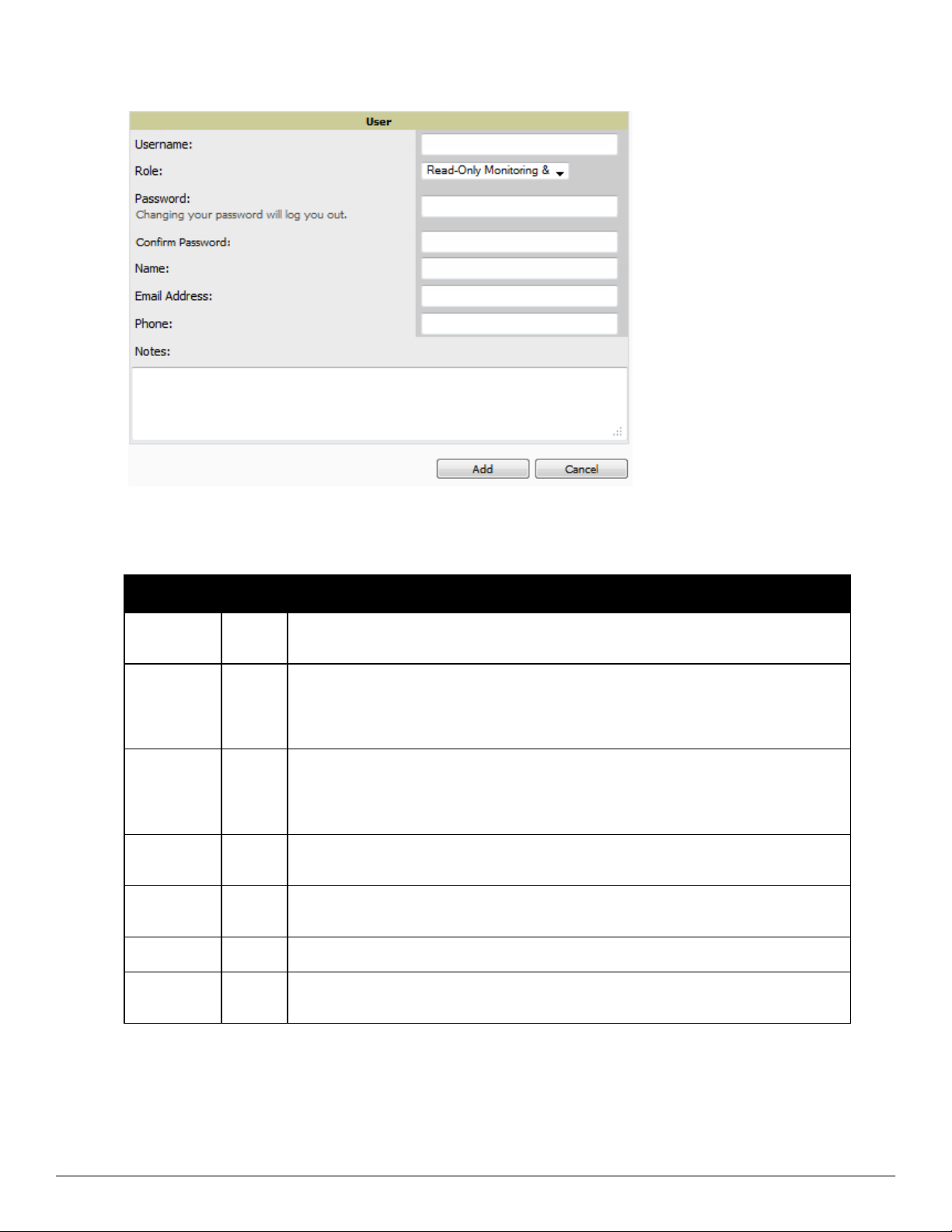
Figure 17: AMP Setup > Users > Add/Edit User Page Illustration
3. Enter or edit the settings on this page. Table 17 describes these settings in additional detail.
Table 17:
AMP Setup > Users > Add/Edit User Fields and Default Values
Setting Default Description
Username None
Role None
Password None
Name None
Email
Address
Phone None Allows you to enter an optional phone number for the user.
Notes None
None
Sets the username as an alphanumeric string. The Username is used when logging in to
AirWave and appears in AirWave log files.
Specifies the user’s Role, which defines the Top viewable folder as well as the type and access
level of the user specified in the previous field.
The admin user defines user roles on the AMP Setup > Roles page, and each user in the system
is assigned to a role.
Sets the password for the user being created or edited. Enter an alphanumeric string without
spaces, and enter the password again in the Confirm Password field.
NOTE: Because the default user's password is identical to the name, it is strongly recommended
that you change this password. Changing your password will log you out.
Allows you to define an optional and alphanumeric text field that takes note of the user's actual
name.
Allows you to specify a specific email address that will propagate throughout many additional
pages in AirWave for that user, including reports, triggers, and alerts.
Enables you to cite any additional notes about the user, including the reason they were granted
access, the user's department, or job title.
4. Select Add to create the new user, Save to retain changes to an existing user, or Cancel to cancel out of this
screen. The user information you have configured appears on the AMP Setup > Users page, and the user
propagates to all other AirWave pages and relevant functions.
28 | Configuring AirWave Dell PowerConnec t W-Air Wave 7.6 | User Guide
Page 41

NOTE: AirWave enables user roles to be created with access to folders within multiple branches of the overall hierarchy. This feature
assists non-administrator users who support a subset of accounts or sites within a single AirWave deployment, such as help desk or
IT staff.
What Next?
l Go to additional tabs in the AMP Setup section to continue additional setup configurations.
l
Complete the required configurations in this chapter before proceeding.
Dell support remains available to you for
any phase of AirWave installation.
AirWave User Roles
The AMP Setup > Roles page defines the viewable devices, the operations that can be performed on devices, and
general AirWave access. User roles can be created that provide users with access to folders within multiple branches
of the overall hierarchy. This feature assists non-administrative users, such as help desk or IT staff, who support a
subset of accounts or sites within a single AirWave deployment. You can restrict user roles to multiple folders within
the overall hierarchy even if they do not share the same top-level folder. Non-admin users are only able to see data
and users for devices within their assigned subset of folders.
User Roles and VisualRF
VisualRF uses the same user roles as defined for AirWave. Users can see floor plans that contain an AP to which
they have access in AirWave, although only visible APs appear on the floor plan. VisualRF users can also see any
building that contains a visible floor plan and any campus that contains a visible building.
NOTE: In VisualRF > Setup > Server Settings, a flag added in AirWave 7.2 allows you to restrict the visibility of empty floor plans to the
role of the user who created them. In previous versions, a floor plan without APs could be visible to all users. By default, this setting
is set to No.
When a new role is added to AirWave, VisualRF must be restarted for the new user to be enabled.
Creating AirWave User Roles
Perform the following steps to view, add, edit, or delete user roles:
1. Go to the AMP Setup > Roles page. This page displays all roles currently configured in AirWave. Figure 18
illustrates the contents and layout of this page.
Figure 18: AMP Setup > Roles Page Illustration
2. Select Add to create a new role, select the pencil icon to edit an existing role, or select a checkbox and select
Delete to remove that role from AirWave. When you select Add or the edit icon, the Add/Edit Role page
appears, illustrated in Figure 19.
Dell PowerConnect W-AirWave 7.6 | User Guide Configuring AirWave | 29
Page 42
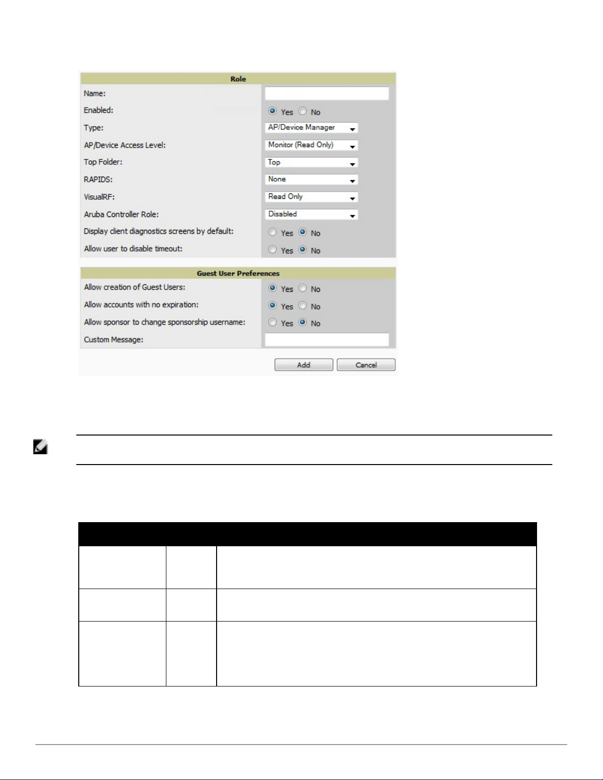
Figure 19: AMP Setup > Roles > Add/Edit Role Page Illustration
3. Enter or edit the settings on this page. As explained earlier in this section, Roles define the type of user-level
access, the user-level privileges, and the view available to the user for device groups and devices in AirWave. The
available configuration options differ for each role type.
NOTE: Most users will see two sections on this page: Role and Guest User Preferences. The Guest User Preferences section will not
appear, however, if Guest User Configuration is disabled in AMP Setup > General.
The following tables describe the available settings and default values for each role type.
Table 18:
AMP Setup > Roles > Add/Edit Roles Fields and Default Values for AMP Administrator Role
Setting Default Description
Sets the administrator-definable string that names the role. The role name should
Name None
Enabled Yes
Type
AP/Device
Manager
indicate the devices and groups that are viewable, as well as the privileges granted to
that role.
Disables or enables the role. Disabling a role prevents all users of that role from
logging in to AirWave.
Defines the type of role.
AMP Administrator—The AirWave Administrator has full access to AirWave and all of
the devices. Only the AirWave Administrator can create new users or access the AMP
Setup page, the VisualRF > Setup page, VisualRF > Audit Log page, System > AMP
Events, and System > Performance.
30 | Configuring AirWave Dell PowerConnec t W-Air Wave 7.6 | User Guide
Page 43

Setting Default Description
Enables or disables Single Sign-On for the role. If enabled, allows the role to
Dell Controller Role Disabled
directly access Dell controller UIs from the Quick Links or IP Address hypertext
throughout AirWave without having to enter credentials for the controller.
Allow user to disable
timeout
No Whether a user can disable AirWave’s timeout feature.
Custom Message none A custom message can also be included.
Table 19:
AMP Setup > Roles > Add/Edit Roles Fields and Default Values for AP/Device Manager Role
Setting Default Description
Name None
Enabled Yes
Type
AP/Device
Access Level
AP/Device
Manager
Monitor
(Read
Only)
Sets the administrator-definable string that names the role. The role name should indicate the
devices and groups that are viewable, as well as the privileges granted to that role.
Disables or enables the role. Disabling a role prevents all users of that role from logging in to
AirWave.
Defines the type of role.
AP/Device Manager—AP/Device Managers have access to a limited number of devices and
groups based on the Top folder and varying levels of control based on the Access Level.
Defines the privileges the role has over the viewable APs. AirWave supports three privilege
levels, as follows:
l Manage (Read/Write)—Manage users can view and modify devices and Groups.
Selecting this option causes a new field, Allow authorization of APs/Devices, to appear
on the page, and is enabled by default.
l Audit (Read Only)—Audit users have read only access to the viewable devices and
Groups. Audit users have access to the APs/Devices > Audit page, which may contain
sensitive information including AP passwords.
l Monitor (Read Only)—Monitor users have read-only access to devices and groups and
VisualRF. Monitor users cannot view the APs/Devices > Audit page which may contain
sensitive information, including passwords.
Defines the highest viewable folder for the role. The role is able to view all devices and
groups contained by the specified top folder. The top folder and its subfolders must contain
all of the devices in any of the groups it can view.
NOTE: AirWave enables user roles to be created with access to folders within multiple
Top Folder Top
branches of the overall hierarchy. This feature assists non-administrator users who support a
subset of accounts or sites within a single AirWave deployment, such as help desk or IT staff.
User roles can be restricted to multiple folders within the overall hierarchy, even if they do
not share the same top-level folder. Non-administrator users are only able to see data and
users for devices within their assigned subset of folders.
Allow
authorization
of
Yes
NOTE: This option is only available when the AP/Device Access Level is specified as Manage
(Read/Write).
APs/Devices
Sets the RAPIDS privileges, which are set separately from the APs/Devices. This field
RAPIDS None
Dell PowerConnect W-AirWave 7.6 | User Guide Configuring AirWave | 31
specifies the RAPIDS privileges for the role, and options are as follows:
l None— Cannot view the RAPIDS tab or any Rogue APs.
l Read Only—The user can view the RAPIDS pages but cannot make any changes to rogue
Page 44

Setting Default Description
APs or perform OS scans.
l Read/Write—The user may edit individual rogues, classification, threat levels and notes,
and perform OS scans.
l Administrator—Has the same privileges as the Read/Write user, but can also set up
RAPIDS rules, override scores and is the only user who can access the RAPIDS > Setup
page.
Sets the VisualRF privileges, which are set separately from the APs/Devices. Options are as
follows:
VisualRF Read Only
l Read Only—The user can view the VisualRF pages but cannot make any changes to floor
plans.
l Read/Write—The user may edit individual floor plans, buildings, and campuses.
Dell
Controller
Role
Display client
diagnostics
screens by
default
Allow user to
disable
timeout
Allow
creation of
Guest Users
Allow
accounts with
no expiration
Allow sponsor
to change
sponsorship
username
Enables or disables Single Sign-On for the role. If enabled, allows the role to directly
Disabled
access Dell controller UIs from the Quick Links or IP Address hypertext throughout AirWave
without having to enter credentials for the controller
No
Sets the role to support helpdesk users with parameters that are specific to the needs of
helpdesk personnel supporting users on a wireless network.
No Whether a user can disable AirWave’s timeout feature.
If this option is enabled, users with an assigned role of Monitoring or Audit can be given
access to guest user account creation along with the option to allow a sponsor to change its
Yes
username.
NOTE: This option is not available if the AP/Device Access Level is specified as Manage
(Read/Write).
Yes
Specifies whether to allow accounts that have no expiration set. If this is set to No, then enter
the amount of time that can elapse before the access expires.
No Specifies whether a sponsor can change the sponsorship user name.
Custom
Message
.
Table 20:
none A custom message can also be included.
AMP Setup > Roles > Add/Edit Roles Fields and Default Values for Guest Access Sponsor Role
Setting Default Description
Name None
Enabled Yes
Type
32 | Configuring AirWave Dell PowerConnec t W-Air Wave 7.6 | User Guide
AP/Device
Sets the administrator-definable string that names the role. The role name should indicate the
devices and groups that are viewable, as well as the privileges granted to that role.
Disables or enables the role. Disabling a role prevents all users of that role from logging in to
AirWave.
Defines the type of role.
Page 45

Setting Default Description
Guest Access Sponsor—Limited-functionality role to allow helpdesk or reception desk staff to
Manager
Top Folder Top
Allow user to
disable
No Whether a user can disable AirWave’s timeout feature.
timeout
Allow
accounts
with no
Yes
expiration
Allow
sponsor to
change
No Specifies whether a sponsor can change the sponsorship user name.
sponsorship
username
grant wireless access to temporary personnel. This role only has access to the defined top
folder of APs.
Defines the Top viewable folder for the role. The role is able to view all devices and groups
contained by the Top folder. The top folder and its subfolders must contain all of the devices
in any of the groups it can view.
NOTE: AirWave enables user roles to be created with access to folders within multiple
branches of the overall hierarchy. This feature assists non-administrator users who support a
subset of accounts or sites within a single AirWave deployment, such as help desk or IT staff.
User roles can be restricted to multiple folders within the overall hierarchy, even if they do
not share the same top-level folder. Non-administrator users are only able to see data and
users for devices within their assigned subset of folders.
Specifies whether to allow accounts that have no expiration set. If this is set to No, then enter
the amount of time that can elapse before the access expires.
Custom
Message
none A custom message can also be included.
What Next?
l Go to additional tabs in the AMP Setup section to continue additional setup configurations. The next section
describes how to set up AirWave users.
l
Complete the required configurations in this chapter before proceeding.
Dell support remains available to you for
any phase of AirWave configuration.
Configuring Login Message, TACACS+, RADIUS, and LDAP Authentication
AirWave uses session-based authentication with a configurable login message and idle timeout. As an option, you
can set AirWave to use an external user database to simplify password management for AirWave administrators and
users. This section contains the following procedures to be followed in AMP Setup > Authentication:
l "Setting Up Login Configuration Options" on page 34
l "Setting Up Certificate Authentication" on page 34
l "Setting Up Single Sign-On" on page 34
l "Specifying the Authentication Priority" on page 35
l "Configuring RADIUS Authentication and Authorization" on page 35
l "Integrating a RADIUS Accounting Server" on page 36
l "Configuring TACACS+ Authentication" on page 37
l "Configuring LDAP Authentication and Authorization" on page 39
Dell PowerConnect W-AirWave 7.6 | User Guide Configuring AirWave | 33
Page 46

Setting Up Login Configuration Options
On the AMP Setup > Authentication page, administrators can optionally configure AirWave’s user idle timeout or
a message-of-the-day that appears when a user first logs in, as shown in Figure 20:
Figure 20: Login configuration field and results in AirWave Login page
1. Go to AMP Setup > Authentication.
2. Complete the fields described on Table 21:
Table 21:
Field Default Description
Max AMPUser Idle
Timeout
Login message none A persistent message that will appear for all of this AirWave’s users after they log in.
3. Select Save when you are finished or follow the next procedure to configure Single Sign-On, TACACS+, LDAP,
Login Configuration section of AMP Setup > Authentication
60
and RADIUS Authentication options.
Number of minutes of idle time until AirWave automatically ends the user session.
Affects all users of this AirWave. The range is 5-240 minutes.
Setting Up Single Sign-On
On the AMP Setup > Authentication page, administrators can set up single sign-on (SSO) for users that have
access to AirWave controllers. This allows users to log in to AirWave and use the IP Address or Quick Links
hypertext links across AirWave to access the controller’s UI without having to enter credentials again. The links the
user can select to access a controller can be found on the APs/Devices > Monitor page in the Device Info section,
and on device list pages.
Perform the following steps to enable this feature for this AMP.
1. Locate the Single Sign-On section in AMP Setup > Authentication.
2. In the Enable Single Sign-On field, select Yes.
3. Select Save if you are finished or follow the next procedure to specify the authentication priority.
Setting Up Certificate Authentication
On the AMP Setup > Authentication page, administrators can specify whether to require a certificate during
authentication and whether to use two-factor authentication. A PEM-encoded certificate bundle is required for this
feature.
This feature must be enabled per role in AMP Setup > Roles.
Perform the following steps to enable this feature for this AMP.
1. Locate the Certificate Authentication section in AMP Setup > Authentication.
2. In the Enable Certificate Authentication field, select Yes.
34 | Configuring AirWave Dell PowerConnec t W-Air Wave 7.6 | User Guide
Page 47

3. Specify whether to require a certificate in order to authenticate. If Yes, then you can also specify whether to use
two-factor authentication.
4. Enter the PEM-encoded CA certificate bundle.
5. Select Save if you are finished or follow the next procedure to specify the authentication priority.
Specifying the Authentication Priority
To specify the authentication priority for this AMP, locate the Authentication Priority section in AMP Setup >
Authentication, and select either Local or Remote as the priority.
If Local is selected, then remote will be attempted if a user is not available. If Remote is selected, then the local
database is searched if remote authentication fails. The order of remote authentication is RADIUS first, followed by
TACACS, and finally LDAP.
Select Save if you are finished or follow the next procedure to configure RADIUS, TACACS+, and LDAP
Authentication options.
Configuring RADIUS Authentication and Authorization
For RADIUS capability, you must configure the IP/Hostname of the RADIUS server, the TCP port, and the server
shared secret. Perform these steps to configure RADIUS authentication:
1. Go to the AMP Setup > Authentication page. This page displays current status of RADIUS. Figure 21
illustrates this page.
Figure 21: AMP Setup > Authentication Page Illustration for RADIUS
2. Select No to disable or Yes to enable RADIUS authentication. If you select Yes, several new fields appear.
Complete the fields described in Table 22.
Table 22:
AMP Setup > Authentication Fields and Default Values for RADIUS Authentication
Field Default Description
Primary Server
Hostname/IP Address
Primary Server Port (1-
65535)
Dell PowerConnect W-AirWave 7.6 | User Guide Configuring AirWave | 35
N/A Enter the IP address or the hostname of the primary RADIUS server.
1812 Enter the TCP port for the primary RADIUS server.
Page 48

Field Default Description
Primary Server Secret N/A Specify and confirm the primary shared secret for the primary RADIUS server.
Confirm Primary Server
Secret
Secondary Server
Hostname/IP Address
Secondary Server Port
(1-65535)
Secondary Server Secret N/A Enter the shared secret for the secondary RADIUS server.
Confirm Secondary
Server Secret
N/A Re-enter the primary server secret.
N/A Enter the IP address or the hostname of the secondary RADIUS server.
1812 Enter the TCP port for the secondary RADIUS server.
N/A Re-enter the secondary server secret.
3. Select Save to retain these configurations, and continue with additional steps in the next procedure.
Integrating a RADIUS Accounting Server
NOTE: AirWave checks the local username and password before checking with the RADIUS server. If the user is found locally, the
local password and role apply. When using RADIUS, it’s not necessary or recommended to define users on the AirWave server. The
only recommended user is the backup admin, in case the RADIUS server goes down.
Optionally, you can configure RADIUS server accounting on AMP Setup > RADIUS Accounting. This capability is
not required for basic AirWave operation, but can increase the user-friendliness of AirWave administration in large
networks. Figure 22 illustrates the settings of this optional configuration interface.
Perform the following steps and configurations to enable AirWave to receive accounting records from a separate
RADIUS server. Figure 22 illustrates the display of RADIUS accounting clients already configured, and Figure 23
illustrates the Add RADIUS Accounting Client page.
Figure 22: AMP Setup > RADIUS Accounting Page Illustration
36 | Configuring AirWave Dell PowerConnec t W-Air Wave 7.6 | User Guide
Page 49

Figure 23: AMP Setup > RADIUS > Add RADIUS Accounting Client Page Illustration
1. To specify the RADIUS authentication server or network, browse to the AMP Setup > RADIUS Accounting
page, select Add, illustrated in Figure 23, and provide the information in Table 23.
2. Complete the following fields:
Table 23:
AMP Setup > Radius Accounting Fields and Default Values for LDAP Authentication
Setting Default Description
Specify the IP address for the authentication server if you only want to accept packets from
IP/Network None
Nickname None Sets a user-defined name for the authentication server.
Shared Secret
(Confirm)
None
one device. To accept packets from an entire network enter the IP/Netmask of the network
(for example, 10.51.0.0/24).
Sets the Shared Secret that is used to establish communication between AirWave and the
RADIUS authentication server.
Configuring TACACS+ Authentication
For TACACS+ capability, you must configure the IP/Hostname of the TACACS+ server, the TCP port, and the
server shared secret. This TACACS+ configuration is for AirWave users and does not affect APs or users logging
into APs.
1. Go to the AMP Setup > Authentication page. This page displays current status of TACACS+. Figure 24
illustrates this page when neither TACACS+, LDAP, nor RADIUS authentication is enabled in AirWave.
Figure 24: AMP Setup > Authentication Page Illustration for TACACS+
Dell PowerConnect W-AirWave 7.6 | User Guide Configuring AirWave | 37
Page 50

2. Select No to disable or Yes to enable TACACS+ authentication. If you select Yes, several new fields appear.
Complete the fields described in Table 24.
Table 24:
AMP Setup > Authentication Fields and Default Values for TACACS+ Authentication
Field Default Description
Primary Server Hostname/IP
Address
Primary Server Port (1-65535) 49 Enter the port for the primary TACACS+ server.
Primary Server Secret N/A
Confirm Primary Server Secret N/A Re-enter the primary server secret.
Secondary Server Hostname/IP
Address
Secondary Server Port (1-65535) 49 Enter the port for the secondary TACACS+ server.
Secondary Server Secret N/A Enter the shared secret for the secondary TACACS+ server.
Confirm Secondary Server Secret N/A Re-enter the secondary server secret.
N/A Enter the IP address or the hostname of the primary TACACS+ server.
Specify and confirm the primary shared secret for the primary TACACS+
server.
N/A Enter the IP address or hostname of the secondary TACACS+ server.
3. Select Save and continue with additional steps.
Configuring Cisco ACS to Work with AirWave
To configure Cisco ACS to work with AirWave, you must define a new service named AMP that uses https on the
ACS server.
1. The AMP https service is added to the TACACS+ (Cisco) interface under the Interface Configuration tab.
2. Select a checkbox for a new service.
3. Enter AMP in the service column and https in the protocol column.
4. Select Save.
5. Edit the existing groups or users in TACACS to use the AMP service and define a role for the group or user.
n The role defined on the Group Setup page in ACS must match the exact name of the role defined on the
AMP Setup > Roles page.
n The defined role should use the following format: role=
role=DormMonitoring
<name_of_
AMP
_role>
. One example is as follows:
As with routers and switches, AMP does not need to know usernames.
6. AMP also needs to be configured as an AAA client.
n On the Network Configuration page, select Add Entry.
n Enter the IP address of AirWave as the AAA Client IP Address.
n The secret should be the same value that was entered on the AMP Setup > TACACS+ page.
7. Select TACACS+ (Cisco IOS) in the Authenticate Using drop down menu and select submit + restart.
NOTE: AirWave checks the local username and password store before checking with the TACACS+ server. If the user is found locally,
the local password and local role apply. When using TACAS+, it is not necessary or recommended to define users on the AirWave
server. The only recommended user is the backup administrator, in the event that the TACAS+ server goes down.
38 | Configuring AirWave Dell PowerConnec t W-Air Wave 7.6 | User Guide
Page 51
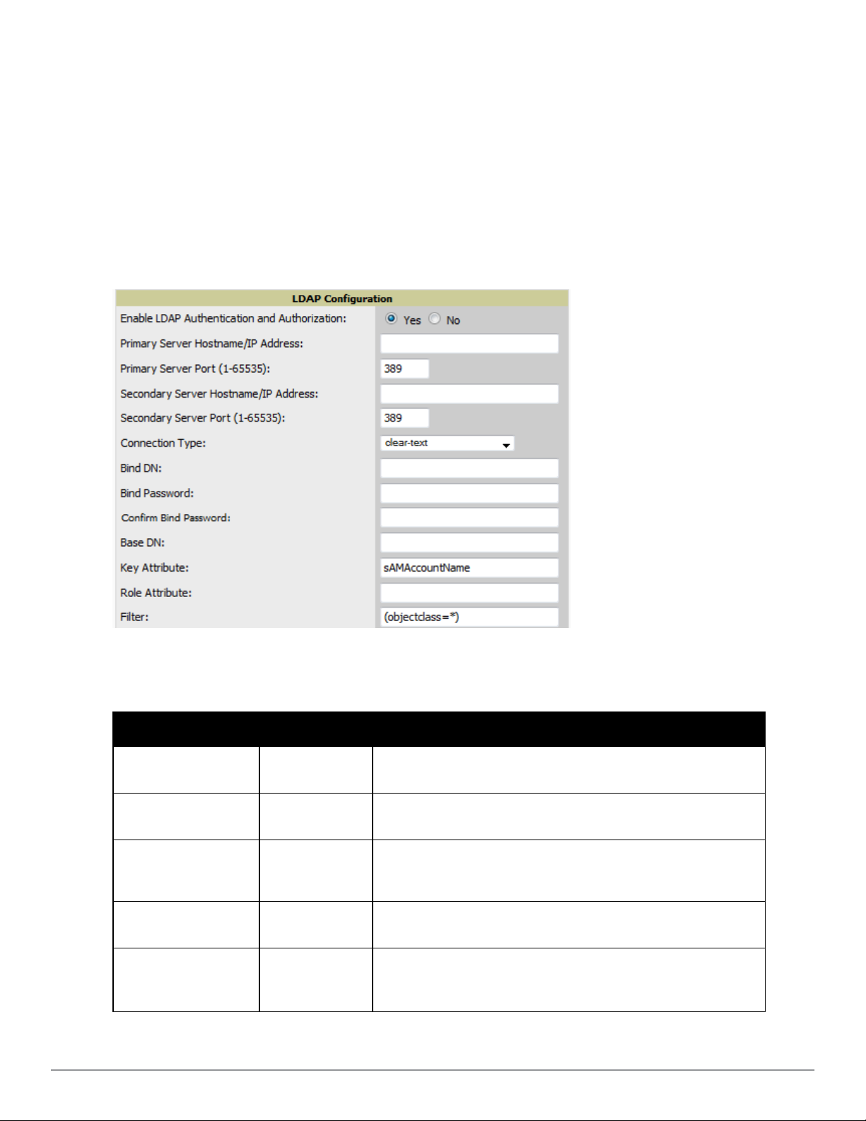
Configuring LDAP Authentication and Authorization
LDAP (Lightweight Directory Access Protocol) provides users with a way of accessing and maintaining distributed
directory information services over a network. When LDAP is enabled, a client can begin a session by authenticating
against an LDAP server which by default is on TCP port 389.
Perform these steps to configure LDAP authentication:
1. Go to the AMP Setup > Authentication page.
2. Select the Yes radio button to enable LDAP authentication and authorization. Once enabled, the available
LDAP configuration options will display. Figure 25 illustrates this page.
Figure 25: AMP Setup > Authentication Page Illustration for LDAP
3. Complete the fields described in Table 25.
Table 25:
AMP Setup > Authentication Fields and Default Values for LDAP Authentication
Field Default Description
Primary Server
Hostname/IP Address
Primary Server Port (1-
65535)
Secondary Server
Hostname/IP Address
Secondary Server Port
(1-65535)
Connection Type clear-text
none Enter the IP address or the hostname of the primary LDAP server.
389 Enter the port where the LDAP server is listening. The default port is 389.
Optionally enter the IP address or hostname of the secondary LDAP
none
389
server. This server will be contacted in the event that the primary LDAP
server is not reachable.
Enter the port where the LDAP service is listening on the secondary
LDAP server. The default port is 389.
Specify one of the following connection types between AirWave and the
LDAP server:
l clear-text results in unencrypted communication.
Dell PowerConnect W-AirWave 7.6 | User Guide Configuring AirWave | 39
Page 52

Field Default Description
l ldap-s results in communication over SSL.
l start-tls uses certificates to initiate encrypted communication.
If Connection Type is configured as start-tls, then also specify whether
the start-tls connection type uses a certificate.
l none - The server may provide a certificate, but it will not be verified.
This may mean that you are connected to the wrong server.
View Server Certificate none
LDAP Server CA
Certificate
Bind DN none
none
l optional - Verifies only when the servers offers a valid certificate.
l require - The server must provide a valid certificate.
A valid LDAP Server CA Certificate must be provided in case of optional
or require. Certificates uploaded on the Device Setup > Certificates page
with a type of Intermediate CA or Trusted CA are listed in the drop down
for LDAP Server CA Certificate.
Specify the LDAP server certificate to use to initiate encrypted
communication. Only certificates that have been uploaded with a type of
Intermediate CA or Trusted CA will appear in this drop down.
NOTE: This LDAP Server CA Certificate drop down menu oly appears if
View Server Certificate is specified as optional or require.
Specify the Distinguished Name (DN) of the administrator account, such
as ‘cn=admin01,cn=admin,dn=domain,dn=com’. Note that for the Active
directory, the bind DN can also be in the administrator@domain format
(for example, adminstrator@acme.com).
Bind Password none Specify the bind DN account password.
Confirm Bind Password none Re-enter the bind password.
The DN of the node in your directory tree from which to start searching
Base DN none
Key Attribute
Role Attribute none
Filter (objectclass=*)
sAMAccountName
for records. Generally, this would be the node that contains all the users
who may access AirWave, for example cn=users,dc=domain,dc=com.
The LDAP attribute that identifies the user, such as ‘sAMAccountName’
for Active Directory
The LDAP attribute that contains the AirWave role, for example
AirWaveRole.
This option limits the object classes in which the key,role attributes
would be searched.
4. Select Save to retain these configurations, and continue with additional steps in the next procedure.
What Next?
l Go to additional subtabs in AMP Setup to continue additional setup configurations.
l
Complete the required configurations in this chapter before proceeding.
Dell support remains available to you for
any phase of AirWave installation.
Enabling AirWave to Manage Your Devices
Once AirWave is installed and active on the network, the next task is to define the basic settings that allow
AirWave to communicate with and manage your devices. Device-specific firmware files are often required or are
highly desirable. Furthermore, the use of Web Auth bundles is advantageous for deployment of Cisco WLC wireless
LAN controllers when they are present on the network.
This section contains the following procedures:
40 | Configuring AirWave Dell PowerConnec t W-Air Wave 7.6 | User Guide
Page 53

l "Configuring Communication Settings for Discovered Devices" on page 41
l "Loading Device Firmware Onto AirWave (optional)" on page 43
Configuring Communication Settings for Discovered Devices
To configure AirWave to communicate with your devices, to define the default shared secrets, and to set SNMP
polling information, navigate to the Device Setup > Communication page, illustrated in Figure 26.
Figure 26: Device Setup > Communication Page Illustration
Perform the following steps to define the default credentials and SNMP settings for the wireless network.
1. On the Device Setup > Communication page, locate the Default Credentials area. Enter the credentials for
each device model on your network. The default credentials are assigned to all newly discovered APs.
The Edit button edits the default credentials for newly discovered devices. To modify the credentials for existing
devices, use the APs/Devices > Manage page or the Modify Devices link on the APs/Devices > List page.
NOTE: Community strings and shared secrets must have read-write access for AirWave to configure the devices. Without read-write
access, AirWave may be able to monitor the devices but cannot apply any configuration changes.
2. Browse to the Device Setup > Communication page, locate the SNMP Settings section, and enter or revise the
following information. Table 26 lists the settings and default values.
Table 26:
Device Setup > Communication > SNMP Settings Fields and Default Values
Setting Default Description
SNMP
Timeout (3-60
sec)
SNMP Retries
(1-40)
3
3
Sets the time, in seconds, that AirWave waits for a response from a device after sending
an SNMP request.
Sets the number of times AirWave tries to poll a device when it does not receive a
response within the SNMP Timeout Period or the Group's Missed SNMP Poll Threshold
setting (1-100). If AirWave does not receive an SNMP response from the device after the
specified number of retries, AirWave classifies that device as Down.
NOTE: Although the upper limit for this value is 40, some SNMP libraries still have a hard
limit of 20 retries. In these cases, any retry value that is set above 20 will still stop at 20.
Dell PowerConnect W-AirWave 7.6 | User Guide Configuring AirWave | 41
Page 54

3. Locate the SNMPv3 Informs section. Select the Add button to reveal configuration options. AirWave users will
need to configure all v3 users that are configured on the controller. The SNMP Inform receiver in the AirWave
will be restarted when users are changed or added to the controller.
l Username - Username of the SNMP v3 user as configured on the controller.
l Auth Protocol - Can be MD5 or SHA. The default setting is SHA.
l Auth and Priv Protocol Passphrases - Enter the authentication and privilege protocol passphrases for the user
as configured on the controller.
l Priv Protocol - Can be DES or AES. The default setting is DES..
NOTE: This form allows you to edit existing SNMPv3 users by selecting the pencil icon next to the desired user. It also allows you to
remove existing users by selecting the user’s checkbox and then clicking Delete.
4. Locate the Telnet/SSH Settings section, and complete or adjust the default value for the field. Table 27 shows
the setting and default value.
Table 27:
Device Setup > Communication > Telnet/SSH Settings Fields and Default Values
Setting Default Description
Telnet/SSH Timeout
(3-120 sec)
10 Sets the timeout period in seconds used when performing Telnet and SSH commands.
5. Locate the HTTP Discovery Settings section and adjust the default value. Table 28 shows the setting and
default value.
Table 28:
Device Setup > Communication > HTTP Discovery Settings Fields and Default Values
Setting Default Description
HTTP Timeout
(3-120 sec)
5 Sets the timeout period in seconds used when running an HTTP discovery scan.
6. Locate the ICMP Settings section and adjust the default value as required. Table 29 shows the setting and
default value.
Table 29:
Device Setup > Communication > ICMP Settings Fields and Default Values
Setting Default Description
Attempt to
ping devices
that were
unreachable
via SNMP
Yes
l When Yes is selected, AirWave attempts to ping the AP device.
l Select No if performance is affected in negative fashion by this function. If a large
number of APs are unreachable by ICMP, likely to occur where there is in excess of 100
APs, the timeouts start to impede network performance.
NOTE: If ICMP is disabled on the network, select No to avoid the performance penalty
caused by numerous ping requests.
7. Locate the Symbol 4131 and Cisco Aironet IOS SNMP Initialization area. Select one of the options listed.
Table 30 describes the settings and default values
42 | Configuring AirWave Dell PowerConnec t W-Air Wave 7.6 | User Guide
Page 55

Table 30:
Device Setup > Communication > Symbol 4131 and Cisco Aironet IOS SNMP Initialization
Fields and Default Values
Setting Default Description
Do Not Modify
SNMP Settings
Enable readwrite SNMP
Yes
No
When selected, specifies that AirWave not modify any SNMP settings. If SNMP is not
already initialized on the Symbol, Nomadix, and Cisco IOS APs, AirWave is not able to
manage them.
When selected, and when on networks where the Symbol, Nomadix, and Cisco IOS APs do
not have SNMP initialized, this setting enables SNMP so the devices can be managed by
AirWave.
Loading Device Firmware Onto AirWave (optional)
AirWave enables automated firmware distribution to the devices on your network. Once you have downloaded the
firmware files from the vendor, you can upload this firmware to AirWave for distribution to devices via the Device
Setup > Upload Firmware & Files page.
This page lists all firmware files on AirWave with file information. This page also enables you to add new firmware
files, to delete firmware files, and to add New Web Auth Bundle files.
The following additional pages support firmware file information:
l Firmware files uploaded to AirWave appear as an option in the drop-down menu on the Groups > Firmware
page and as a label on individual APs/Devices > Manage pages.
l Use the AMP Setup page to configure AirWave-wide default firmware options.
Table 31 below itemizes the contents, settings, and default values for the Upload Firmware & Files page.
Table 31:
Device Setup > Upload Firmware & Files Fields and Default Values
Setting Default Description
Dell PowerConnect W-
Type
Owner Role None
Description None Displays a user-configurable text description of the firmware file.
Server Protocol None
Use Group File
Server
Firmware
Filename
Firmware MD5
Checksum
Firmware File Size
Series Controller (any
model)
None If enabled, displays the name of the file server supporting the group.
None
None
None Displays the size of the firmware file in bytes.
Displays a drop-down list of the primary AP makes and models that
AirWave supports with automated firmware distribution.
Displays the user role that uploaded the firmware file. This is the role
that has access to the file when an upgrade is attempted.
Displays the file transfer protocol by which the firmware file was
obtained from the server. This can be either FTP or TFTP.
Displays the name of the file that was uploaded to AirWave and to be
transferred to an AP when the file is used in an upgrade.
Displays the MD5 checksum of the file after it was uploaded to
AirWave. The MD5 checksum is used to verify that the file was
uploaded to AirWave without issue. The checksum should match the
checksum of the file before it was uploaded.
Dell PowerConnect W-AirWave 7.6 | User Guide Configuring AirWave | 43
Page 56

Setting Default Description
Firmware Version None
HTML Filename None
HTML MD5
Checksum
HTML File Size None Supporting HTML, displays the size of the file in bytes.
HTML Version None Supporting HTML, displays the version of HTML used for file transfer.
Desired Firmware
File for Specified
Groups
None
None
Displays the firmware version number. This is a user-configurable
field.
Supporting HTML, displays the name of the file that was uploaded to
AirWave and to be transferred to an AP when the file is used in an
upgrade.
Supporting HTML, displays the MD5 checksum of the file after it was
uploaded to AirWave. The MD5 checksum is used to verify that the file
was uploaded to AirWave without issue. The checksum should match
the checksum of the file before it was uploaded.
The firmware file is set as the desired firmware version on the Groups
> Firmware Files page of the specified groups. You cannot delete a
firmware file that is set as the desired firmware version for a group.
Loading Firmware Files onto AirWave
Perform the following steps to load a device firmware file onto AirWave:
1. Go to the Device Setup > Upload Firmware & Files page.
2. Select Add. The Add Firmware File page appears. Figure 27 illustrates this page.
Figure 27: Device Setup > Upload Firmware and Files > Add Page Illustration
3. Select the Supported Firmware Versions and Features link to view supported firmware versions.
NOTE: Unsupported and untested firmware may cause device mismatches and other problems. Please contact Dell support at
dell.com/support before installing non-certified firmware.
4. Enter the appropriate information and select Add. The file uploads to AirWave and once complete, this file
appears on the Device Setup > Upload Firmware & Files page. This file also appears on additional pages that
display firmware files (such as the Group > Firmware page and on individual APs/Devices > Manage pages).
5. You can also import a CSV list of groups and their external TFTP firmware servers. Table 32 itemizes the
settings of this page.
44 | Configuring AirWave Dell PowerConnec t W-Air Wave 7.6 | User Guide
Page 57

Table 32:
Supported Firmware Versions and Features Fields and Default Values
Setting Default Description
Indicates the firmware file is used with the specified type. If you
select an IOS device from the Type drop-down menu, you have
the option of choosing a server protocol of TFTP or FTP. If you
choose FTP, you may later notice that the firmware files are
pushed to the device more quickly.
With selection of some types, particularly Cisco controllers, you
can specify the boot software version.
Type
Dell PowerConect WSeries Controller
Firmware
Version
Description
Upload firmware
files (and use
built-in firmware)
Use an external
firmware file
server
Server Protocol TFTP
Use Group File
Server
Firmware File
Server IP
Address
None
None Provides a user-configurable text description of the firmware file.
Enabled
N/A
Disabled
None
Provides a user-configurable field to specify the firmware version
number. This open appears if Use an external firmware file server
is enabled.
Allows you to select a firmware from your local machine and
upload it via TFTP or FTP.
You can also choose to assign the external TFTP server on a pergroup basis. If you select this option, you must enter the IP
address on the Groups > Firmware page. Complete the Firmware
File Server IP Address field.
Specify whether to use a built-in TFTP server or FTP to upload a
firmware file. TFTP is recommended. If you select FTP, AirWave
uses an anonymous user for file upload.
If you opt to use an external firmware file server, this additional
option appears. This setting instructs AirWave to use the server
that is associated with the group instead of defining a server.
Provides the IP address of the External TFTP Server (like
SolarWinds) used for the firmware upgrade. This option displays
when the user selects the Use an external firmware file option.
Enter the name of the firmware file that needs to be uploaded.
Firmware
Filename
HTML Filename None
Patch Filename None
Boot Software
Version
NOTE: Additional fields may appear for multiple device types. AirWave prompts you for additional firmware information as required.
For example, Intel and Symbol distribute their firmware in two separate files: an image file and an HTML file. Both files must be
uploaded to AirWave for the firmware to be distributed successfully via AirWave.
None
None
Ensure that the firmware file is in the TFTP root directory. If you
are using a non-external server, you select Choose File to find
your local copy of the file.
Browse to the HTML file that will accompany the firmware
upload. Note that this field is only available for certain Firmware
File Types (for example, Symbol 4121).
If you selected Symbol WS5100 as the Firmware File Type, and
you are upgrading from version 3.0 to 3.1, then browse to the path
where the patch file is located.
If you specified a Cisco WLC device as the Firmware File Type,
then also enter the boot software version.
6. Select Add to import the firmware file.
Dell PowerConnect W-AirWave 7.6 | User Guide Configuring AirWave | 45
Page 58

To delete a firmware file that has already been uploaded to AirWave, return to the Device Setup > Upload
Firmware & Files page, select the checkbox for the firmware file and select Delete.
NOTE: A firmware file may not be deleted if it is the desired version for a group. Use the Group > Firmware page to investigate this
potential setting and status.
Using Web Auth Bundles in AirWave
Web authentication bundles are configuration files that support Cisco WLC wireless LAN controllers. This
procedure requires that you have local or network access to a Web Auth configuration file for Cisco WLC devices.
Perform these steps to add or edit Web Auth bundles in AirWave.
1. Go to the Device Setup > Upload Firmware & Files page. This page displays any existing Web Auth bundles
that are currently configured in AirWave, and allows you to add or delete Web Auth bundles.
2. Scroll to the bottom of the page. Select the Add New Web Auth Bundle button to create a new Web Auth
bundle (see Figure 28), or select the pencil icon next to an existing bundle to edit. You may also delete Web
Auth bundles by selecting that bundle with the checkbox, and selecting Delete.
Figure 28: Add Web Auth Bundle Page Illustration
3. Enter a descriptive label in the description field. This is the label used to identify and track Web Auth bundles
on the page.
4. Enter the path and filename of the Web Auth configuration file in the Web Auth Bundle field or select Choose
File to locate the file.
5. Select Add to complete the Web Auth bundle creation, or Save if replacing a previous Web Auth configuration
file, or Cancel to abort the Web Auth integration.
For additional information and a case study that illustrates the use of Web Auth bundles with Cisco WLC
controllers, refer to the following document on Cisco’s Web site:
l Wireless LAN controller Web Authentication Configuration Example, Document ID: 69340
http://www.cisco.com/en/US/tech/tk722/tk809/technologies_configuration_example09186a008067489f.shtml
Setting Up Device Types
On AMP Setup > Device Type Setup, you can define how the Device Type displayed for users on your network is
calculated from available data. The first matching property is used. These rules cannot be edited or deleted, but only
reordered or enabled.
You can change the priority order of rules by dragging and dropping rows, as shown in Figure 29.
Check or uncheck the checkbox under the Enabled column to turn device setup rules on or off.
Refer to "Monitoring and Supporting WLAN Clients" on page 201 for more information on the Device Type column
that appears in Clients list tables.
46 | Configuring AirWave Dell PowerConnec t W-Air Wave 7.6 | User Guide
Page 59
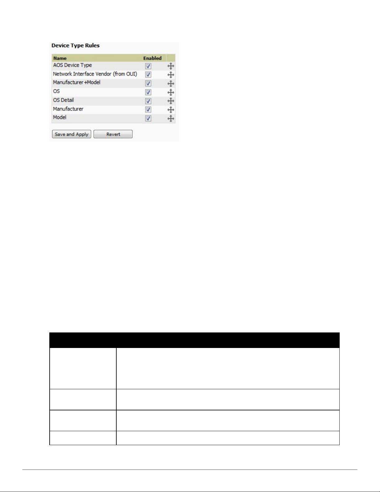
Figure 29: AMP Setup > Device Type Setup Page Illustration
Configuring Cisco WLSE and WLSE Rogue Scanning
The Cisco Wireless LAN Solution Engine (WLSE) includes rogue scanning functions that AirWave supports. This
section contains the following topics and procedures, and several of these sections have additional sub-procedures:
l "Introduction to Cisco WLSE" on page 47
l "Initial WLSE Configuration" on page 48
l "Configuring IOS APs for WDS Participation" on page 49
l "Configuring ACS for WDS Authentication" on page 50
l "Configuring Cisco WLSE Rogue Scanning" on page 50
You must enter one or more CiscoWorks WLSE hosts to be polled for discovery of Cisco devices and rogue AP
information.
Introduction to Cisco WLSE
Cisco WLSE functions as an integral part of the Cisco Structured Wireless-Aware Network (SWAN) architecture,
which includes IOS Access Points, a Wireless Domain Service, an Access Control Server, and a WLSE. In order for
AirWave to obtain Rogue AP information from the WLSE, all SWAN components must be properly configured.
Table 33 describes these components.
Table 33:
SWAN Component Requirements
WDS (Wireless Domain
Services)
WLSE (Wireless LAN
Solution Engine)
ACS (Access Control
Server)
Cisco SWAN Architecture Components
l WDS Name
l Primary and backup IP address for WDS devices (IOS AP or WLSM)
l WDS Credentials APs within WDS Group
NOTE: WDS can be either a WLSM or an IOS AP. WLSM (WDS) can control up to 250 access
points. AP (WDS) can control up to 30 access points.
l IP Address
l Login
l IP Address
l Login
APs l APs within WDS Group
Dell PowerConnect W-AirWave 7.6 | User Guide Configuring AirWave | 47
Page 60

Initial WLSE Configuration
Use the following general procedures to configure and deploy a WLSE device in AirWave:
l "Adding an ACS Server for WLSE" on page 48
l "Enabling Rogue Alerts for Cisco WLSE" on page 48
l "Configuring WLSE to Communicate with APs" on page 48
l "Discovering Devices" on page 48
l "Managing Devices" on page 49
l "Inventory Reporting" on page 49
l "Defining Access" on page 49
l "Grouping" on page 49
Adding an ACS Server for WLSE
1. Go to the Devices > Discover > AAA Server page.
2. Select New from the drop-down list.
3. Enter the Server Name, Server Port (default 2002), Username, Password, and Secret.
4. Select Save.
Enabling Rogue Alerts for Cisco WLSE
1. Go to the Faults > Network Wide Settings > Rogue AP Detection page.
2. Select the Enable.
3. Select Apply.
Additional information about rogue device detection is available in "Configuring Cisco WLSE Rogue Scanning" on
page 50.
Configuring WLSE to Communicate with APs
1. Go to the Device Setup > Discover page.
2. Configure SNMP Information.
3. Configure HTTP Information.
4. Configure Telnet/SSH Credentials
5. Configure HTTP ports for IOS access points.
6. Configure WLCCP credentials.
7. Configure AAA information.
Discovering Devices
The following three methods can be used to discover access points within WLSE:
l Using Cisco Discovery Protocol (CDP)
l Importing from a file
l Importing from CiscoWorks
Perform these steps to discover access points.
1. Go to the Device > Managed Devices > Discovery Wizard page.
2. Import devices from a file.
3. Import devices from Cisco Works.
4. Import using CDP.
48 | Configuring AirWave Dell PowerConnec t W-Air Wave 7.6 | User Guide
Page 61

Managing Devices
Prior to enabling radio resource management on IOS access points, the access points must be under WLSE
management.
NOTE: AirWave becomes the primary management/monitoring vehicle for IOS access points, but for AirWave to gather Rogue
information, the WLSE must be an NMS manager to the APs.
Use these pages to make such configurations:
1. Go to Device > Discover > Advanced Options.
2. Select the method to bring APs into management Auto, or specify via filter.
Inventory Reporting
When new devices are managed, the WLSE generates an inventory report detailing the new APs. AirWave accesses
the inventory report via the SOAP API to auto-discover access points. This is an optional step to enable another
form of AP discovery in addition to AirWave, CDP, SNMP scanning, and HTTP scanning discovery for Cisco IOS
access points. Perform these steps for inventory reporting.
1. Go to Devices > Inventory > Run Inventory.
2. Run Inventory executes immediately between WLSE polling cycles.
Defining Access
AirWave requires System Admin access to WLSE. Use these pages to make these configurations.
1. Go to Administration > User Admin.
2. Configure Role and User.
Grouping
It’s much easier to generate reports or faults if APs are grouped in WLSE. Use these pages to make such
configurations.
1. Go to Devices > Group Management.
2. Configure Role and User.
Configuring IOS APs for WDS Participation
IOS APs (1100, 1200) can function in three roles within SWAN:
l Primary WDS
l Backup WDS
l WDS Member
AirWave monitors AP WDS role and displays this information on AP Monitoring page.
NOTE: APs functioning as WDS Master or Primary WDS will no longer show up as Down is the radios are enabled.
WDS Participation
Perform these steps to configure WDS participation.
1. Log in to the AP.
2. Go to the Wireless Services > AP page.
3. Select Enable participation in SWAN Infrastructure.
Dell PowerConnect W-AirWave 7.6 | User Guide Configuring AirWave | 49
Page 62

4. Select Specified Discovery, and enter the IP address of the Primary WDS device (AP or WLSM).
5. Enter the Username and Password for the WLSE server.
Primary or Secondary WDS
Perform these steps to configure primary or secondary functions for WDS.
1. Go to the Wireless Services > WDS > General Setup page.
2. If the AP is the Primary or Backup WDS, select Use the AP as Wireless Domain Services.
n Select Priority (set 200 for Primary, 100 for Secondary).
n Configure the Wireless Network Manager (configure the IP address of WLSE).
3. If the AP is Member Only, leave all options unchecked.
4. Go to the Security > Server Manager page.
5. Enter the IP address and Shared Secret for the ACS server and select Apply.
6. Go to the Wireless Services > WDS > Server Group page.
7. Enter the WDS Group of the AP.
8. Select the ACS server in the Priority 1 drop-down menu and select Apply.
Configuring ACS for WDS Authentication
ACS authenticates all components of the WDS and must be configured first. Perform these steps to make this
configuration.
1. Login to the ACS.
2. Go to the System Configuration > ACS Certificate Setup page.
3. Install a New Certificate by selecting the Install New Certificate button, or skip to the next step if the
certificate was previously installed.
4. Select User Setup in the left frame.
5. Enter the Username that will be used to authenticate into the WDS and select Add/Edit.
6. Enter the Password that will be used to authenticate into the WDS and select Submit.
7. Go to the Network Configuration > Add AAA Client page.
8. Add AP Hostname, AP IP Address, and Community String (for the key).
9. Enter the Password that will be used to authenticate into the WDS and select Submit.
For additional and more general information about ACS, refer to "Configuring ACS Servers " on page 52.
Configuring Cisco WLSE Rogue Scanning
The AMP Setup > WLSE page allows AirWave to integrate with the Cisco Wireless LAN Solution Engine
(WLSE). AirWave can discover APs and gather rogue scanning data from the Cisco WLSE.
Figure 30 illustrates and itemizes the AirWave settings for communication that is enabled between AirWave and
WLSE.
50 | Configuring AirWave Dell PowerConnec t W-Air Wave 7.6 | User Guide
Page 63
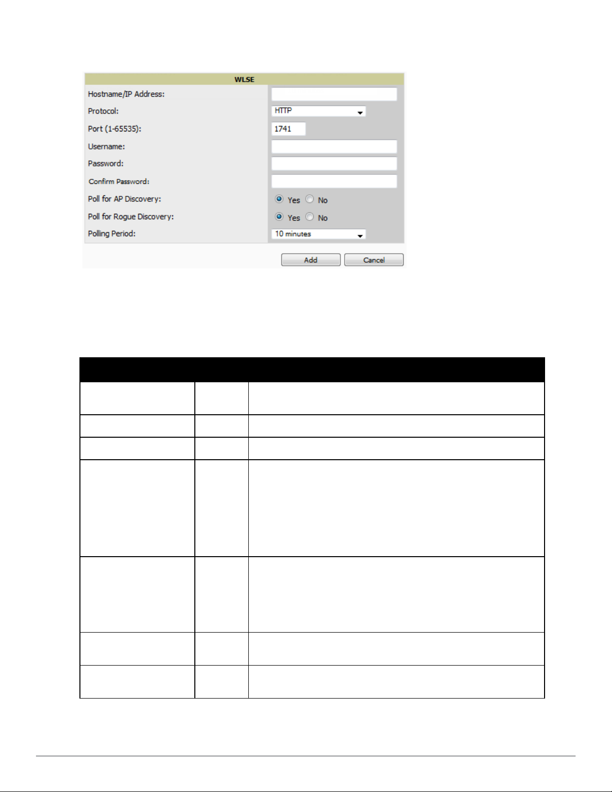
Figure 30: AMP Setup > WLSE > Add New WLSE Page Illustration
Perform the following steps for optional configuration of AirWave for support of Cisco WLSE rogue scanning.
1. To add a Cisco WLSE server to AirWave , navigate to the AMP Setup > WLSE page and select Add. Complete
the fields in this page. Table 34 describes the settings and default values.
Table 34:
AMP Setup > WLSE Fields and Default Values
Setting Default Description
Hostname/IP Address
Protocol
Port
Username
Password
None
HTTP Specify whether to use HTTP or HTTPS when polling the WLSE.
1741 Defines the port AirWave uses to communicate with the WLSE server.
None
None
Designates the IP address or DNS Hostname for the WLSE server, which must
already be configured on the Cisco WLSE server.
Defines the username AirWave uses to communicate with the WLSE server.
The username and password must be configured the same way on the WLSE
server and on AirWave.
The user needs permission to display faults to discover rogues and inventory
API (XML API) to discover manageable APs. As derived from a Cisco
limitation, only credentials with alphanumeric characters (that have only
letters and numbers, not other symbols) allow AirWave to pull the necessary
XML APIs.
Defines the password AirWave uses to communicate with the WLSE server.
The username and password must be configured the same way on the WLSE
server and on AirWave.
As derived from a Cisco limitation, only credentials with alphanumeric
characters (that have only letters and numbers, not other symbols) allow
AirWave to pull the necessary XML APIs.
Poll for AP Discovery;
Poll for Rogue Discovery
Polling Period
Dell PowerConnect W-AirWave 7.6 | User Guide Configuring AirWave | 51
Yes
10 minutes
Sets the method by which AirWave uses WLSE to poll for discovery of new
APs and/or new rogue devices on the network.
Determines how frequently AirWave polls WLSE to gather rogue scanning
data.
Page 64

2. After you have completed all fields, select Save. AirWave is now configured to gather rogue information from
WLSE rogue scans. As a result of this configuration, any rogues found by WLSE appear on the RAPIDS > List
page.
What Next?
l Go to additional tabs in the AMP Setup section to continue additional setup configurations.
l
Complete the required configurations in this chapter before proceeding.
any phase of AirWave installation.
Dell support remains available to you for
Configuring ACS Servers
This is an optional configuration. The AMP Setup > ACS page allows AirWave to poll one or more Cisco ACS
servers for wireless username information. When you specify an ACS server, AirWave gathers information about your
wireless users. Refer to "Setting Up Device Types" on page 46 if you want to use your ACS server to manage your
AirWave users.
Perform these steps to configure ACS servers:
1. Go to the AMP Setup > ACS page. This page displays current ACS setup, as illustrated in Figure 31.
Figure 31: AMP Setup > ACS Page Illustration
2. Select Add to create a new ACS server, or select a pencil icon to edit an existing server. To delete an ACS server,
select that server and select Delete. When selecting Add or edit, the Details page appears, as illustrated in Figure
32.
Figure 32: AMP Setup > ACS > Add/Edit Details Page Illustration
3. Complete the settings on AMP Setup > ACS > Add/Edit Details. Table 35 describes these fields:
52 | Configuring AirWave Dell PowerConnec t W-Air Wave 7.6 | User Guide
Page 65

Table 35:
AMP Setup > ACS > Add/Edit Details Fields and Default Values
Field Default Description
IP/Hostname
Protocol
Port
Username
Password
Polling
Period
None Sets the DNS name or the IP address of the ACS Server.
HTTP
2002
None Sets the Username of the account AirWave uses to poll the ACS server.
None Sets the password of the account AirWave uses to poll the ACS server.
10 min
Launches a drop-down menu specifying the protocol AirWave uses when it polls the ACS
server.
Sets the port through which AirWave communicates with the ACS. AirWave generally
communicates via SNMP traps on port 162.
Launches a drop-down menu that specifies how frequently AirWave polls the ACS server for
username information.
4. Select Add to finish creating the new ACS server, or Save to finish editing an existing ACS server.
5. The ACS server must have logging enabled for passed authentications. Enable the Log to CSV Passed
Authentications report option, as follows:
n Log in to the ACS server, select System Configuration, then in the Select frame, select Logging.
n Under Enable Logging, select CSV Passed Authentications. The default logging options function and support
AirWave. These include the two columns AirWave requires: User-Name and Caller-ID.
What Next?
l Go to additional tabs in the AMP Setup section to continue additional setup configurations.
l
Complete the required configurations in this chapter before proceeding.
Dell support remains available to you for
any phase of AirWave installation.
Integrating AirWave with an Existing Network Management Solution (NMS)
This is an optional configuration. The AMP Setup > NMS configuration page allows AirWave to integrate with
other Network Management Solution (NMS) consoles. This configuration enables advanced and interoperable
functionality as follows:
l AirWave can forward WLAN-related SNMP traps to the NMS, or AirWave can send SNMPv1 or SNMPv2 traps
to the NMS.
l AirWave can be used in conjunction with Hewlett-Packard’s ProCurve Manager.
l The necessary files for either type of NMS interoperability are downloaded from the AMP Setup > NMS page as
follows. For additional information, contact support.
Perform these steps to configure NMS support in AirWave:
1. Go to AMP Setup > NMS, illustrated in Figure 33.
Figure 33: AMP Setup > NMS Page Illustration
2. Select Add to integrate a new NMS server, or select the pencil icon to edit an existing server. Provide the
information described in Table 36:
Dell PowerConnect W-AirWave 7.6 | User Guide Configuring AirWave | 53
Page 66

Table 36:
AMP Setup > NMS Integration Add/Edit Fields and Default Values
Setting Default Description
Hostname None Cites the DNS name or the IP address of the NMS.
Port 162
Community String None Sets the community string used to communicate with the NMS.
SNMP Version 2C Sets the SNMP version of the traps sent to the Host.
Enabled Yes Enables or disables trap logging to the specified NMS.
Send Configuration Traps Yes Enables NMS servers to transmit SNMP configuration traps.
Sets the port AirWave uses to communicate with the NMS.
NOTE: AirWave generally communicates via SNMP traps on port 162.
3. The NMS Integration Add/Edit page includes the Netcool/OMNIbus Integration link to information and
instructions. The IBM Tivoli Netcool/OMNIbus operations management software enables automated event
correlation and additional features resulting in optimized network uptime.
4. The NMS Integration Add/Edit page includes the HP ProCurve Manager Integration link. Select this link for
additional information, zip file download, and brief instructions for installation with AirWave. Select Add to
finish creating the NMS server or Save to configure an existing NMS server.
What Next?
l Go to additional tabs in the AMP Setup section to continue additional setup configurations.
l
Complete the required configurations in this chapter before proceeding.
Dell support remains available to you for
any phase of AirWave installation.
Auditing PCI Compliance on the Network
This section describes PCI requirements and auditing functions in AirWave. It includes the following topics:
l "Introduction to PCI Requirements" on page 54
l "PCI Auditing" on page 55
l "Enabling or Disabling PCI Auditing" on page 56
Introduction to PCI Requirements
AirWave supports wide security standards and functions in the wireless network. One component of network security
is the optional deployment of Payment Card Industry (PCI) Auditing.
The Payment Card Industry (PCI) Data Security Standard (DSS) establishes multiple levels in which payment
cardholder data is protected in a wireless network. AirWave supports PCI requirements according to the standards
and specifications set forth by the following authority:
l Payment Card Industry (PCI) Data Security Standard (DSS)
n PCI Security Standards Council Web site
https://www.pcisecuritystandards.org
n
PCI Quick Reference Guide
https://www.pcisecuritystandards.org/pdfs/pci_ssc_quick_guide.pdf
, Version 1.2 (October 2008)
54 | Configuring AirWave Dell PowerConnec t W-Air Wave 7.6 | User Guide
Page 67

PCI Auditing
PCI Auditing in AirWave allows you to monitor, audit, and demonstrate PCI compliance on the network. There are
five primary pages in which you establish, monitor, and access PCI auditing, as follows:
l The AMP Setup > PCI Compliance page enables or disables PCI Compliance monitoring on the network, and
displays the current compliance status on the network. See "Enabling or Disabling PCI Auditing" on page 56.
l The Reports > Definitions page allows you to create custom-configured and custom-scheduled PCI Compliance
reports. See "Reports > Definitions Page Overview" on page 235.
l The Reports > Generated page lists PCI Compliance reports currently available, and allows you to generate the
latest daily version of the PCI Compliance Report with a single select. Refer to "Reports > Generated Page
Overview" on page 237.
l The APs/Devices > PCI Compliance page enables you to analyze PCI Compliance for any specific device on the
network. This page is accessible when you select a specific device from the APs/Devices > Monitor page. First,
you must enable this function through AMP Setup. See "Enabling or Disabling PCI Auditing" on page 56.
l The PCI Compliance Report offers additional information. Refer to "Using the PCI Compliance Report" on
page 252. This report not only contains Pass or Fail status for each PCI requirement, but cites the action
required to resolve a Fail status when sufficient information is available.
NOTE: When any PCI requirement is enabled on AirWave, then AirWave grades the network as pass or fail for the respective PCI
requirement. Whenever a PCI requirement is not enabled in AirWave, then AirWave does not monitor the network’s status in relation
to that requirement, and cannot designate Pass or Fail network status. AirWave users without RAPIDS visibility enabled will not see
the 11.1 PCI requirements in the PCI Compliance Report.
Table 37:
PCI Requirements and Support in AirWave
Requirement Description
Monitoring configuration standards for network firewall devices
When Enabled: PCI Requirement 1.1 establishes firewall and router configuration standards.
1.1
1.2.3
2.1
2.1.1
A device fails Requirement 1.1 if there are mismatches between the desired configuration and the
configuration on the device.
When Disabled: firewall router and device configurations are not checked for PCI compliance, and
Pass or Fail status is not reported or monitored.
Monitoring firewall installation between any wireless networks and the cardholder data
environment
When Enabled: A device passes requirement 1.2.3 if it can function as a stateful firewall.
When Disabled: firewall router and device installation are not checked for PCI compliance.
Monitoring the presence of vendor-supplied default security settings
When Enabled: PCI Requirement 2 establishes the standard in which all vendor-supplied default
passwords are changed prior to a device’s presence and operation in the network.
A device fails requirement 2.1 if the username, passwords or SNMP credentials being used by
AirWave to communicate with the device are on a list of forbidden default credentials. The list
includes common vendor default passwords, for example.
When Disabled: device passwords and other vendor default settings are not checked for PCI
compliance.
Changing vendor-supplied defaults for wireless environments
When Enabled: A device fails requirement 2.1.1 if the passphrases, SSIDs, or other security-related
settings are on a list of forbidden values that AirWave establishes and tracks. The list includes
common vendor default passwords. The user can input new values to achieve compliance.
When Disabled: network devices are not checked for forbidden information and PCI Compliance is
not established.
Dell PowerConnect W-AirWave 7.6 | User Guide Configuring AirWave | 55
Page 68

Requirement Description
Using strong encryption in wireless networks
When Enabled: PCI Requirement 4 establishes the standard by which payment cardholder data is
encrypted prior to transmission across open public networks. PCI disallows WEP encryption as an
4.1.1
11.4
approved encryption method after June 20, 2010. A device fails requirement 4.1.1 if the desired or
actual configuration reflect that WEP is enabled on the network, or if associated users can connect
with WEP.
When Disabled: AirWave cannot establish a pass or fail status with regard to PCI encryption
requirements on the network.
Using intrusion-detection or intrusion-prevention systems to monitor all traffic
When Enabled: AirWave reports pass or fail status when monitoring devices capable of reporting
IDS events. Recent IDS events are summarized in the PCI Compliance report or the IDS Report.
When Disabled: AirWave does not monitor the presence of PCI-compliant intrusion detection or
prevention systems, nor can it report Pass or Fail status with regard to IDS events.
Enabling or Disabling PCI Auditing
Perform these steps to verify status and to enable or disable AirWave support for PCI 1.2 requirements. enabling one
or all PCI standards on AirWave enables real-time information and generated reports that advise on Pass or Fail
status. The PCI auditing supported in AirWave is reported in Table 1 in the "PCI Auditing" on page 55 section.
1. To determine what PCI Compliance standards are enabled or disabled on AirWave, navigate to the AMP Setup
> PCI Compliance page, illustrated in Figure 34.
Figure 34: AMP Setup > PCI Compliance page illustration
2. To enable, disable, or edit any category of PCI Compliance monitoring in AirWave, select the pencil icon next to
the category. The Default Credential Compliance page displays for the respective PCI standard.
3. Create changes as required. The edit pages will vary based on the PCIRequirement that you select. Figure 35
shows an example of how to edit the PCI 2.1 requirement.
56 | Configuring AirWave Dell PowerConnec t W-Air Wave 7.6 | User Guide
Page 69

Figure 35: Default Credential Compliance for PCI Requirements
4. Select Save.
5. To view and monitor PCI auditing on the network, use generated or daily reports. See Creating, Running, and
Emailing Reports. In addition, you can view the real-time PCI auditing of any given device online. Perform these
steps:
a. Go to the APs/Devices > List page.
b. Select a specific device. The Monitor page for that device displays. The APs/Devices page also displays a
Compliance subtab in the menu bar.
c. Select Compliance to view complete PCI compliance auditing for that specific device.
Deploying WMS Offload
Overview of WMS Offload in AirWave
This section describes the Dell PowerConnect W-Series Wireless LAN Management Server (WMS) offload
infrastructure. WMS Offload is supported with the following two requirements:
l ArubaOS Version 2.5.4 or later
l AirWave Version 6.0 or later
The Dell PowerConnect W WMS feature is an enterprise-level hardware device and server architecture with
managing software for security and network policy. There are three primary components of the WMS deployment:
l Air Monitor AP devices establish and monitor RF activity on the network.
l The WMS server manages devices and network activity to include rogue AP detection and enforcement of
network policy.
l The AirWave graphical user interface (GUI) allows users to access and use the WMS functionality.
WMS Offload
master controllers provide this data so that AirWave can support rigorous network monitoring capabilities.
Refer to:
l "General Configuration Tasks Supporting WMS Offload in AirWave" on page 58
l "Additional Information Supporting WMS Offload" on page 58
is the ability to place the burden of the WMS server data and GUI functions on AirWave. WMS
Dell PowerConnect W-AirWave 7.6 | User Guide Configuring AirWave | 57
Page 70

General Configuration Tasks Supporting WMS Offload in AirWave
WMS Offload must be enabled with a six-fold process and related configuration tasks as follows:
1. Configure WLAN switches for optimal AirWave monitoring.
a. Disable debugging.
b. Ensure AirWave server is a trap receiver host.
c. Ensure proper traps are enabled.
2. Configure AirWave to optimally monitor the AirWave infrastructure.
a. Enable WMS offload on the AMP Setup > General page.
b. Configure SNMP communication.
c. Create a proper policy for monitoring the AirWave infrastructure.
d. Discover the infrastructure.
3. Configure device classification.
a. Set up rogue classification.
b. Set up rogue classification override.
c. Establish user classification override devices.
4. Deploy ArubaOS-specific monitoring features.
a. Enable remote AP and wired network monitoring.
b. View controller license information.
5. Convert existing floor plans to VisualRF to include the following elements:
n Dell PowerConnect W-Series ArubaOS
n RF Plan
6. Use RTLS for increasing location accuracy (optional).
a. Enable RTLS service on the AirWave server.
b. Enable RTLS on ArubaOS infrastructure.
Additional Information Supporting WMS Offload
Refer to the
information, including detailed concepts, configuration procedures, restrictions, ArubaOS infrastructure, and
AirWave version differences in support of WMS Offload.
Dell PowerConnect W-AirWave 7.6 Best Practices Guide
at dell.com/support/manuals for additional
58 | Configuring AirWave Dell PowerConnec t W-Air Wave 7.6 | User Guide
Page 71

Chapter 3
Configuring and Using Device Groups
This chapter describes the deployment of device groups within AirWave. The section below describes the pages or
focused subtabs available on the Groups tab. Note that the available subtabs can vary significantly from one device
group to another—one or more subtabs may not appear, depending on the Default Group display option selected on
the AMP Setup > General page and the types of devices you add to AirWave.
Figure 36: Subtabs under the Group tab
l List—This page is the default page in the Groups section of AirWave. It lists all groups currently configured in
AirWave and provides the foundation for all group-level configurations. See "Viewing All Defined Device Groups"
on page 61.
l Monitor—This page displays client and bandwidth usage information, lists devices in a given group, provides an
Alert Summary table for monitoring alerts for the group, and provides a detailed Audit Log for group-level
activity.
l Basic—This page appears when you create a new group on the Groups > List page. Once you define a group
name, AirWave displays the Basic page from which you configure many group-level settings. This page remains
available for any device group configured in AirWave. Refer to "Configuring Basic Group Settings" on page 62.
l Templates—This page manages templates for any device group. Templates allow you to manage the
configuration of Dell PowerConnect W-Series, 3Com, Alcatel-Lucent, Aruba Networks, Cisco Aironet IOS, Cisco
Catalyst switches, Enterasys, HP, Nortel, Symbol and Trapeze devices in a given group using a configuration file.
Variables in such templates configure device-specific properties, such as name, IP address and channel. Variables
also define group-level properties. For additional information about using the Templates page, refer to "Creating
and Using Templates" on page 151.
l Security—This page defines general security settings for device groups, to include RADIUS, encryption, and
additional security settings on devices. Refer to "Configuring Group Security Settings" on page 70.
l SSIDs—This page sets SSIDs, VLANs, and related parameters in device groups. Refer to "Configuring Group
SSIDs and VLANs" on page 74.
l AAA Servers—This page configures authentication, authorization, and accounting settings in support of
RADIUS servers for device groups. Refer to "Adding and Configuring Group AAA Servers" on page 69.
l Radio—This page defines general 802.11 radio settings for device groups. Refer to "Configuring Radio Settings
for Device Groups" on page 78.
l Dell PowerConnect W Config—This page manages ArubaOS Device Groups, AP Overrides, and other profiles
specific to Dell PowerConnect W-Series devices on the network. Use this page as an alternative to the Device
Setup > Dell PowerConnect W Config page. The appearance of this page varies depending on whether AMP is
configured for global configuration or group configuration. For additional information, refer to the
PowerConnect W-AirWave Configuration Guide
l Cisco WLC Config—This page consolidates controller-level settings from the Group Radio, Security, SSIDs,
at dell.com/support/manuals.
Cisco WLC Radio and AAA Server pages into one navigation tree that is easier to navigate, and has familiar
layout and terminology. Bulk configuration for per-thin AP settings, previously configured on the Group LWAPP
Dell
Dell PowerConnect W-AirWave 7.6 | User Guide Configuring and Using Device Groups | 59
Page 72

APs tab, can now be performed from Modify Devices on the APs/Devices > List page. Refer to "Cisco WLC
Group Configuration" on page 81.
l PTMP—This page defines settings specific to Proxim MP devices when present. As such, this page is only
available when a Proxim MP device is added to this group. Refer to "Configuring Group PTMP Settings" on page
88.
l Proxim Mesh—This page defines mesh AP settings specific to Proxim devices when present. Refer to
"Configuring Proxim Mesh Radio Settings" on page 89.
l MAC ACL—This page defines MAC-specific settings that apply to Proxim, Symbol, and ProCurve 520 devices
when present. Refer to "Configuring Group MAC Access Control Lists" on page 91.
l Firmware—This page manages firmware files for many devices. Refer to "Specifying Minimum Firmware Versions
for APs in a Group" on page 91.
l Compare—This page allows you to compare line item-settings between two device groups. On the Groups >
List page, select the Compare two groups link, select the two groups from the drop-down menus, and then select
Compare. Refer to "Comparing Device Groups" on page 92.
This chapter also provides the following additional procedures for group-level configurations:
l "Deleting a Group" on page 93
l "Changing Multiple Group Configurations " on page 94
l "Modifying Multiple Devices" on page 95
l "Using Global Groups for Group Configuration" on page 98
AirWave Groups Overview
Enterprise APs, controllers, routers, and switches have hundreds of variable settings that must be configured precisely
to achieve optimal performance and network security. Configuring all settings on each device individually is time
consuming and error prone. AirWave addresses this challenge by automating the processes of device configuration
and compliance auditing. At the core of this approach is the concept of Device Groups, with the following functions
and benefits:
l AirWave allows certain settings to be managed efficiently at the Group level, while others are managed at an
individual device level.
l AirWave defines a
hundreds of devices that share certain common configuration settings.
l
Groups
can be defined based on geography (such as 5th Floor APs), usage or security policies (such as Guest
Access APs), function (such as Manufacturing APs), or any other appropriate variable.
l
Devices
within a group may originate from different vendors or hardware models, but all devices within a Group
share certain basic configuration settings.
Typical group configuration variables include the following settings:
l Basic settings - SSID, SNMP polling interval, and so forth
l Security settings - VLANs, WEP, 802.1x, ACLs, and so forth
l Radio settings - data rates, fragmentation threshold, RTS threshold, DTIM, preamble, and so forth.
When configuration changes are applied at a
group. Such changes must be applied with every device in Managed mode. Monitor mode is the more common
mode.
Group
as a subset of the devices on the wireless LAN, ranging in size from one device to
group level
, they are assigned automatically to every device within that
CAUTION: Always review the Audit page before pushing configuration to a device or group.
60 | Configuring and Using Device Groups Del l PowerConnect W-Ai rWave 7.6 | User Guide
Page 73

Individual device settings—such as device name, RF channel selection, RF transmission power, antenna settings, and
so forth—typically should not be managed at a group level and must be individually configured for optimal
performance. Individual AP settings are configured on the APs/Devices > Manage page.
You can create as many different groups as required. Administrators usually establish groups that range in size from
five to 100 wireless devices.
Group configuration can be enhanced with the AirWave
Global Groups
feature, which lets you create Global Groups
with configurations that are pushed to individual Subscriber Groups.
Viewing All Defined Device Groups
To display a list of all defined groups, browse to the Groups > List page, illustrated in Figure 37.
Figure 37: Groups > List Page Illustration (partial view)
Table 38 describes the columns in the Groups > List page.
Table 38:
Column Description
Add New Group
Groups > List Columns
Launches a page that enables you to add a new group by name and to define group parameters for
devices in that group. For additional information, refer to "Configuring Basic Group Settings" on page
62.
Manage
(wrench icon)
Name
Up/Down Status
Polling Period
Total Devices Total number of devices contained in the group including APs, controllers, routers, or switches.
Changes Displays when a group has unapplied changes.
Is Global Group
Global Group Specifies which group this Subscriber Group is using as its template.
SSID The SSID assigned to supported device types within the group.
Down
Goes to the Groups > Basic configuration page for that group. Hover your mouse over the icon to see a
list of shortcuts to group-specific subtabs that would appear across the navigation section if this group is
selected. (See Figure 38 in "Configuring Basic Group Settings" on page 62.)
Uniquely identifies the group by location, vendor, department or any other identifier (such as ‘Accounting
APs,’ ‘Floor 1 APs,’ ‘Cisco devices,’ ‘802.1x APs,’ and so forth).
The time between Up/Down SNMP polling periods for each device in the group. Detailed SNMP polling
period information is available on the Groups > Basic configuration page. Note that by default, most
polling intervals do not match the up/down period.
If a group is designated as global, it may not contain APs but it may be used as a template for other
groups. This column may also indicate Yes if this group has been pushed to the AirWave from a Master
Console.
The number of access points within the group that are not reachable via SNMP or are no longer
associated to a controller. Note that thin APs are not directly polled with SNMP, but are polled through
Dell PowerConnect W-AirWave 7.6 | User Guide Configuring and Using Device Groups | 61
Page 74
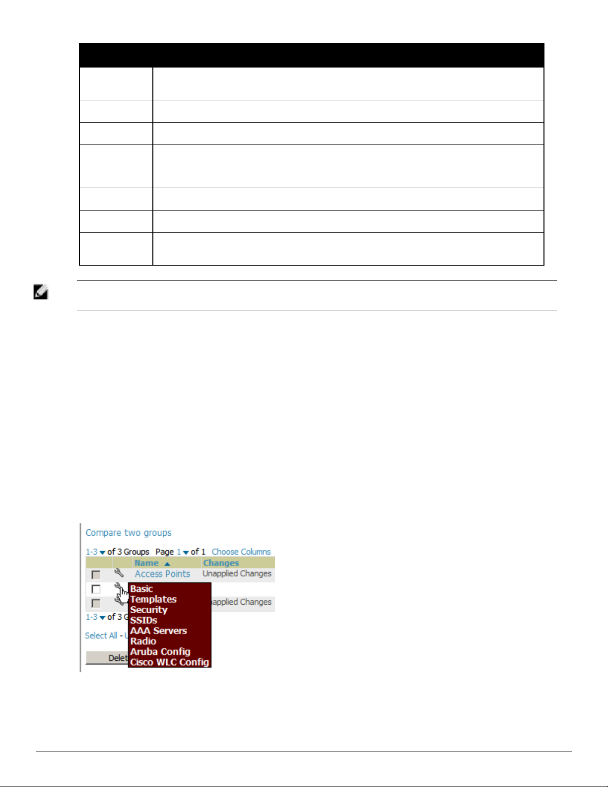
Column Description
the controller. That controller may report that the thin AP is down or is no longer on the controller. At this
point, AirWave classifies the device as down.
Mismatched The number of devices within the group that are in a mismatched state.
Ignored The number of ignored devices in that group.
The number of mobile users associated with all access points within the group. To avoid double counting
Clients
Usage A running average of the sum of bytes in and bytes out for the managed radio page.
VPN Sessions Number of active (connected) VPN sessions under this group.
of clients, clients are only listed in the group of the AP with which they are associated. Note that device
groups with only controllers in them report no clients.
Duplicate
NOTE: When you first configure AirWave, there is only one default group labeled Access Points. If you have no other groups
configured, refer to "Configuring Basic Group Settings" on page 62.
Creates a new group with the name Copy of <Group Name> with identical configuration settings. (Dell
configuration settings will have to be manually added back.)
Configuring Basic Group Settings
The first default device group that AirWave sets up is the Access Points group, but you can use this procedure to
add and configure any device group. Perform these steps to configure basic group settings, then continue to
additional procedures to define additional settings as required.
1. Go to the Groups > List page. Existing device groups appear on this page.
2. To create a new group, select Add. Enter a group name and select Add. The Groups > Basic page appears.
To edit an existing device group, select the manage (wrench) icon next to the group. The Groups > Basic page
appears. If you mouse over an existing group’s wrench, a popup menu allows you to select Basic, Templates,
Security, SSIDs, AAA Servers, Radio, Dell PowerConnect W Config or Cisco WLC Config to edit those pages
as desired, as illustrated in Figure 38.
Figure 38: Pop-up When Hovering over Wrench Icon in Groups > List
Figure 39 illustrates one example of the Groups > Basic page.
62 | Configuring and Using Device Groups Del l PowerConnect W-Ai rWave 7.6 | User Guide
Page 75

Figure 39: Groups > Basic Page Illustration
3. Define the settings in the Basic and Global Group sections. Table 39 describes several typical settings and
default values of this Basic section.
Table 39:
Basic and Global Groups Fields and Default Values
Setting Default Description
Defined when
Name
Missed SNMP
Poll Threshold
(1-100)
Dell PowerConnect W-AirWave 7.6 | User Guide Configuring and Using Device Groups | 63
first adding
the group
1
Displays or changes the group name. As desired, use this field to set the name to
uniquely identify the group by location, vendor, department, or any other identifier (such
as Accounting APs, Cisco devices, 802.1x APs, and so forth).
Sets the number of Up/Down SNMP polls that must be missed before AirWave considers
a device to be down. The number of SNMP retries and the SNMP timeout of a poll can
be set on the Device Setup > Communication page.
Page 76

Setting Default Description
Regulatory
Domain
Timezone
Allow One-toOne NAT
Audit
Configuration
on Devices
Is Global Group No
Use Global
Group
United States
AMP System
Time
No
Yes
No
Sets the regulatory domain in AirWave, limiting the selectable channels for APs in the
group.
Allows group configuration changes to be scheduled relative to the time zone in which
the devices are located. This setting is used for scheduling group-level configuration
changes.
Allows AirWave to talk to the devices on a different IP address than the one configured
on the device.
NOTE: If enabled, the LAN IP Address listed on the AP/Devices > Manage configuration
page under the Settings area is different than the IP Address under the Device
Communication area.
Auditing and pushing of configuration to devices can be disabled on all the devices in
the group. Once disabled, all the devices in the groups will not be counted towards
mismatched devices.
If specified as Yes, then this group can be selected in the Use Global Group drop down
menu for future group configurations.
When enabled, this field allows you to define the device group to be a Global Group.
Refer to "Using Global Groups for Group Configuration" on page 98.
4. Complete the SNMP Polling Periods section. The information in this section overrides default settings. Table
40 describes the SNMP polling settings.
Table 40:
SNMP Polling Periods Fields and Default Values
Setting Default Description
Sets time between Up/Down SNMP polling for each device in the group.
Up/Down Status Polling
Period
Override Polling Period for
Other Services
AP Interface Polling Period 10 minutes
Client Data Polling Period 10 minutes Sets time between SNMP polls for client data for devices in the group.
Thin AP Discovery Polling
Period
Device-to-Device link
Polling Period
802.11 Counters Polling
Period
5 minutes
No
15 minutes
5 minutes
15 minutes Sets time between SNMP polls for 802.11 Counter information.
The Group SNMP Polling Interval overrides the global parameter configured
on the Device Setup > Communication page. An initial polling interval of 5
minutes is best for most networks.
Enables or disables overriding the base SNMP Polling Period. If you select
Yes, the other settings in the SNMP Polling Periods section are activated, and
you can override default values.
Sets the interval at which AirWave polls for radio monitoring and bandwidth
being used by a device.
Sets time between SNMP polls for Thin AP Device Discovery. Controllers are
the only devices affected by this polling interval.
Sets time between SNMP polls for Device-to-Device link polling. Mesh APs
are the only devices affected by this polling interval.
Rogue AP and Device
Location Data Polling Period
64 | Configuring and Using Device Groups Del l PowerConnect W-Ai rWave 7.6 | User Guide
30 minutes
Sets time between SNMP polls for Rogue AP and Device Location Data
polling.
Page 77

Setting Default Description
CDP Neighbor Data Polling
Period
Mesh Discovery Polling
Period
30 minutes
15 minutes Sets time between SNMP polls for Mesh Device Discovery.
Sets the frequency in which this group polls the network for Cisco Discovery
Protocol (CDP) neighbors.
5. To configure support for routers and switches in the group, locate the Routers and Switches section and adjust
these settings as required. This section defines the frequency in which all devices in the group polled. These
settings can be disabled entirely as desired. Table 41 describes the SNMP polling settings.
Table 41:
Routers and Switches Fields and Default Values
Setting Default Description
Sets the frequency in which devices poll routers and switches for Address
Read ARP Table 4 hours
Read CDP Table for Device
Discovery
Read Bridge Forwarding
Table
4 hours
4 hours
Resolution Protocol (ARP) table information. This setting can be disabled, or
set to poll for ARP information in a range from every 15 seconds to 12 hours.
For Cisco devices, sets the frequency in which devices poll routers and
switches for Cisco Discovery Protocol (CDP) information. This setting can be
disabled, or set to poll for CDP neighbor information in a range from every 15
seconds to 12 hours.
Sets the frequency in which devices poll the network for bridge forwarding
information. This setting can be disabled, or set to poll bridge forwarding
tables from switches in a range from every 15 seconds to 12 hours.
Interface Up/Down Polling
Period
Interface Bandwidth Polling
Period
Interface Error Counter
Polling Period
Poll 802.3 error counters No Sets whether 802.3 error counters should be polled.
Poll Cisco interface error
counters
5 minutes
15 minutes
30 minutes
No Sets whether the interface error counters for Cisco devices should be polled.
Sets the frequency in which network interfaces are polled for up/down status.
This setting can be disabled, or set to poll from switches in a range from every
15 seconds to 30 minutes.
Sets the frequency in which network interfaces are polled for bandwidth
usage. This setting can be disabled, or set to poll from switches in a range
from every 5 minutes to 30 minutes.
Sets the frequency in which network interfaces are polled for up/down status.
This setting can be disabled, or set to poll bridge forwarding tables from
switches in a range from every 5 minutes to 30 minutes.
6. Record additional information and comments about the group in the Notes section.
7. To configure which options and tabs are visible for the group, complete the settings in the Group Display
Options section. Table 42 describes the settings and default values.
Table 42:
Group Display Options Fields and Default Values
Setting Default Description
Show device
settings for
Dell PowerConnect W-AirWave 7.6 | User Guide Configuring and Using Device Groups | 65
Only
devices
Drop-down menu determines which Group tabs and options are to be viewable by default in
new groups. Settings include the following:
Page 78

Setting Default Description
l All Devices—AirWave displays all Group tabs and setting options.
l Only devices in this group—AirWave hides all options and tabs that do not apply to the
devices in the group. If you use this setting, then to get the group list to display the
on this
AMP
correct SSIDs for the group, you must Save and Apply on the group.
l Only devices on this AMP— hides all options and tabs that do not apply to the APs and
devices currently on AirWave.
l Use system defaults—Use the default settings on AMP Setup > General
l Selected device types—Allows you to specify the device types for which AirWave
displays Group settings.
Selected Device
Types
N/A
This option appears if you chose to display selected device types, allowing you to select the
device types to display group settings. Use Select devices in this group to display only
devices in the group being configured.
8. To assign dynamically a range of static IP addresses to new devices as they are added into the group, locate the
Automatic Static IP Assignment section on the Groups > Basic configuration page. If you select Yes in this
section, additional fields appear. Complete these fields as required. Table 43 describes the settings and default
values This section is only relevant for a small number of device types, and will appear when they are present.
Table 43:
Automatic Static IP Assignment Fields and Default Values
Setting Default Description
Assign Static IP
Addresses to
Devices
Start IP Address none Sets the first address AirWave assigns to the devices in the Group.
Number of
Addresses
Subnet Mask none Sets the subnet mask to be assigned to the devices in the Group.
Subnet Gateway none Sets the gateway to be assigned to the devices in the Group.
No
none Sets the number of addresses in the pool from which AirWave can assign IP addresses.
Specify whether to enable AirWave to statically assign IP addresses from a specified range
to all devices in the Group. If this value is set to Yes, then the additional configuration fields
described in this table will become available.
Next IP Address none
Defines the next IP address queued for assignment. This field is disabled for the initial
Access Points group.
9. To configure Spanning Tree Protocol on WLC devices and Proxim APs, locate the Spanning Tree Protocol
section on the Groups > Basic configuration page. Adjust these settings as required. Table 44 describes the
settings and default values.
Table 44:
Spanning Tree Protocol Fields and Default Values
Setting Default Description
Spanning Tree
Protocol
Bridge Priority 32768
66 | Configuring and Using Device Groups Del l PowerConnect W-Ai rWave 7.6 | User Guide
No
Specify wehther to enable or disables Spanning Tree Protocol on Proxim APs.If this value
is set to Yes, then the additional configuration fields described in this table will become
available.
Sets the priority for the AP. Values range from 0 to 65535. Lower values have higher
priority. The lowest value is the root of the spanning tree. If all devices are at default the
device with the lowest MAC address will become the root.
Page 79

Setting Default Description
Bridge
Maximum Age
Bridge Hello
Time
Bridge Forward
Delay
20
2 Sets the time, in seconds, between Hello message broadcasts.
15
Sets the maximum time, in seconds, that the device stores protocol information. The
supported range is from 6 to 40.
Sets the time, in seconds, that the port spends in listening and learning mode if the
spanning tree has changed.
10. To configure Network Time Protocol (NTP) settings locate the NTP section and adjust these settings as
required. Table 45 describes the settings and default values.
Table 45:
NTP Fields and Default Values
Setting Default Description
NTP Server #1,
2,3
UTC Time Zone 0
Daylight Saving
Time
None Sets the IP address of the NTP servers to be configured on the AP.
Sets the hour offset from UTC time to local time for the AP. Times displayed in AirWave
graphs and logs use the time set on the AirWave server.
No
Enables or disables the advanced daylight saving time settings in the Proxim section of the
Groups > Basic configuration page.
11. To configure settings specific to Cisco IOS/Catalyst, locate the Cisco IOS/Catalyst section and adjust these
settings as required. Table 46 describes the settings and default values.
Table 46:
Cisco IOS/Catalyst Fields and Default Values
Setting Default Description
SNMP Version 2c The version of SNMP used by AirWave to communicate to the AP.
Cisco IOS CLI
Communication
Cisco IOS Config File
Communication
Telnet
TFTP
The protocol AirWave uses to communicate with Cisco IOS devices. Selecting SSH
uses the secure shell for command line page (CLI) communication and displays an
SSH Version option. Selecting Telnet sends the data in clear text via Telnet.
The protocol AirWave uses to communicate with Cisco IOS devices. Selecting SCP
uses the secure copy protocol for file transfers and displays an SCP Version option.
Selecting TFTP will use the insecure trivial file transfer protocol. The SCP login
and password should be entered in the Telnet username and password fields.
12. To configure settings specific to Cisco WLC, locate the Cisco WLC section and adjust these settings as
required. Table 47 describes the settings and default values.
Table 47:
Cisco WLC Fields and Default Values
Setting Default Description
SNMP Version 2c Sets the version of SNMP used by AirWave to communicate to WLC controllers.
Sets the protocol AirWave uses to communicate with Cisco IOS devices. Selecting
CLI Communication SSH
Dell PowerConnect W-AirWave 7.6 | User Guide Configuring and Using Device Groups | 67
SSH uses the secure shell for command line page (CLI) communication. Selecting
Telnet sends the data in clear text via Telnet.
Page 80

NOTE: When configuring Cisco WLC controllers, refer to "Configuring Wireless Parameters for Cisco Controllers" on page 87.
13. To configure settings specific to Aruba locate the Aruba section and adjust these settings as required. Table 48
describes the settings and default values of this section.
Table 48:
Aruba Fields and Default Values
Setting Default Description
SNMP Version 2c The version of SNMP used by AirWave to communicate to the AP.
Configures commands previously documented in the Dell PowerConnect W-AirWave Best
Practices Guide. When enabled, this feature allows AirWave to display historical
Offload WMS
Database
Dell
PowerConnect W
GUI Config
Ignore Rogues
Discovered by
Remote APs
Delete Certificates
On Controller
No
Yes
No
No Specifies whether to delete the current certificates on an ArubaOS controller.
information for WLAN switches.
Changing the setting to Yes pushes commands via SSH to all WLAN switches in Monitor
Only mode without rebooting the controller. The command can be pushed to controllers in
manage mode (also without rebooting the controller) if the Allow WMS Offload setting on
AMP Setup > General is changed to Yes.
This setting selects whether you'd like to configure your Aruba devices using the
Groups > Dell PowerConnect W Config method (either global or group) or using
Templates.
Configures whether to turn off RAPIDS rogue classification and rogue reporting for RAPs in
this group.
14. To configure settings for 3Com, Enterasys, Nortel, or Trapeze devices, locate the
3Com/Enterasys/Nortel/Trapeze section and define the version of SNMP to be supported.
15. To configure settings for universal devices on the network, including routers and switches that support both wired
and wireless networks, locate the Universal Devices, Routers and Switches section of the Groups > Basic page
and define the version of SNMP to be supported.
16. To control the conditions by which devices are automatically authorized into this group, locate the Automatic
Authorization settings section and adjust these settings as required. Table 49 describes the settings and default
values.
Table 49:
Automatic Authorization Fields and Default Values
Setting Default Description
Whether to auto authorize new controllers to the New Devices List, the same
Add New Controllers
and Autonomous
Devices Location
Add New Thin APs
Location
68 | Configuring and Using Device Groups Del l PowerConnect W-Ai rWave 7.6 | User Guide
Use
Global
Setting
Use
Global
Setting
Group/Folder as the discovering devices, the same Group/Folder as the closest IP
neighbor, and/or a specified auto-authorization group and folder. The Current Global
Setting set in AMP Setup > General is shown below this field. Selecting a different
option overrides the global setting.
Whether to auto authorize new thin APs to the New Devices List, the same
Group/Folder as the discovering devices, the same Group/Folder as the closest IP
neighbor, and/or a specified auto-authorization group and folder. The Current Global
Setting set in AMP Setup > General is shown below. Selecting a different option
overrides the global setting for this group.
Page 81

17. The specify the Virtual Controller Certificates to be applied to this group, locate the Virtual Controller
Certificates settings section and adjust these settings as desired. Table 50 describes the settings and default
values.
Table 50:
Virtual Controller Certificate Fields and Default Values
Setting Default Description
Specify a CA certificate for the virtual controller. The fields in this drop down will
CA Cert None
Server Cert None
populate when a certificate of type Intermediate CA or Trusted CA is added in the
Device Setup > Certificates page.
Specify a server certificate for the virtual controller. The fields in this drop down will
populate when a certificate of type Server Cert is added in the Device Setup >
Certificates page.
18. To automate putting multiple devices in this group into Manage mode at once so that changes can be applied
and have the devices revert to Monitor-Only mode after the maintenance period is over, locate the Maintenance
Windows option and define a new AP Group Maintenance Window.
19. Select Save when the configurations of the Groups > Basic configuration page are complete to retain these
settings without pushing these settings to all devices in the group. Save is a good option if you intend to make
additional device changes in the group, and you want to wait until all configurations are complete before you
push all configurations at one time. Select Save and Apply to make the changes permanent, or select Revert to
discard all unapplied changes.
What Next?
l Continue to additional sections in this chapter to create new groups or to edit existing groups.
l Once general group-level configurations are complete, continue to later chapters in this document to add or edit
additional device-level configurations and to use several additional AirWave functions.
Adding and Configuring Group AAA Servers
Configure RADIUS servers on the Groups > AAA Servers page.
Once defined on this page, RADIUS servers are selectable in the drop-down menus on the Groups > Security and
Groups > SSIDs configuration pages. Perform these steps to create RADIUS servers.
NOTE: TACACS+ servers are configurable only for Cisco WLC devices. Refer to "Configuring Cisco WLC Security Parameters and
Functions" on page 87.
1. Go to the Groups > List page and select the group for which to define AAA servers by selecting the group name.
The Monitor page appears.
2. Select the AAA Servers page. The AAA Servers page appears, enabling you to add a RADIUS server. Figure 40
illustrate this page for AAA RADIUS Servers:
Dell PowerConnect W-AirWave 7.6 | User Guide Configuring and Using Device Groups | 69
Page 82

Figure 40: Groups > AAA Servers Page Illustration
3. To add a RADIUS server or edit an existing server, select Add New RADIUS Server or the corresponding pencil
icon to edit an existing server. Table 51 describes the settings and default values of the Add/Edit page.
Table 51:
Adding a RADIUS Server Fields and Default Values
Setting Default Description
Hostname/IP Address None
Secret and Confirm
Secret
Authentication No Sets the RADIUS server to perform authentication when this setting is enabled with Yes.
Authentication Port
(1-65535)
Accounting No Sets the RADIUS server to perform accounting functions when enabled with Yes.
Accounting Port (1-
65535)
Timeout (0-86400) None
Max Retries
(0-20)
None
1812
1813
None
Sets the IP Address or DNS name for RADIUS Server.
NOTE: IP Address is required for Proxim/ORiNOCO and Cisco Aironet IOS APs.
Sets the shared secret that is used to establish communication between AirWaveand
the RADIUS server.
NOTE: The shared secret entered in AirWave must match the shared secret on the
server.
Appears when Authentication is enabled. Sets the port used for communication
between the AP and the RADIUS server.
Appears when Accounting is enabled.Sets the port used for communication between
the AP and the RADIUS server.
Sets the time (in seconds) that the access point waits for a response from the RADIUS
server.
Sets the number of times a RADIUS request is resent to a RADIUS server before failing.
NOTE: If a RADIUS server is not responding or appears to be responding slowly,
consider increasing the number of retries.
4. Select Add to complete the creation of the RADIUS server, or select Save if editing an existing RADIUS server.
The Groups > AAA Servers page displays this new or edited server. You can now reference this server on the
Groups > Security page.
AirWave supports reports for subsequent RADIUS Authentication. These are viewable by selecting Reports >
Generated, scrolling to the bottom of the page, and selecting Latest RADIUS Authentication Issues Report.
5. To make additional RADIUS configurations for device groups, use the Groups > Security page and continue to
the next topic.
Configuring Group Security Settings
The Groups > Security page allows you to set security policies for APs in a device group:
70 | Configuring and Using Device Groups Del l PowerConnect W-Ai rWave 7.6 | User Guide
Page 83
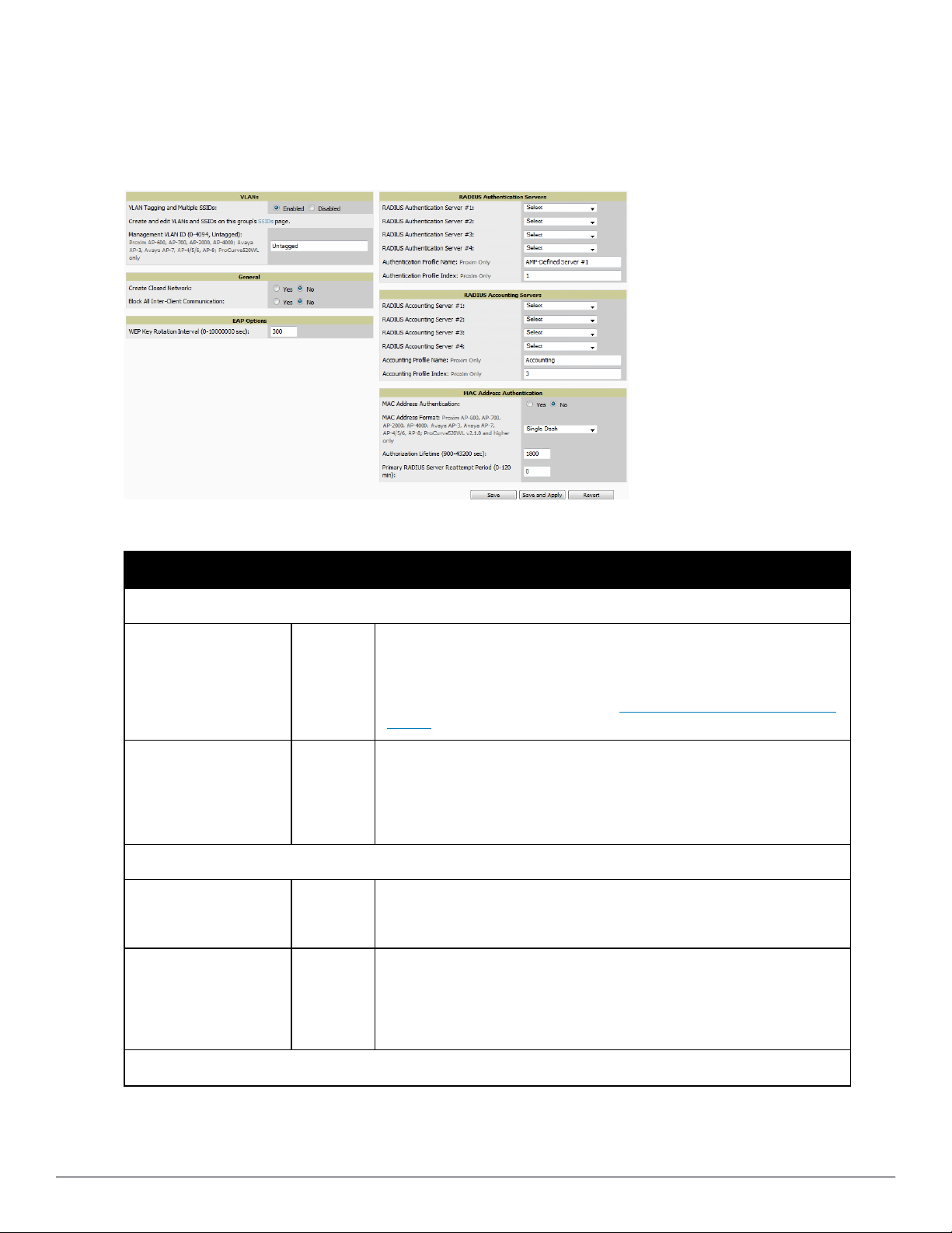
1. Select the device group for which to define security settings from the Groups > List page.
2. Go to Groups > Security. Some controls on this page interact with additional AirWave pages. Figure 41
illustrates this page and Table 52 explains the fields and default values.
Figure 41: Groups > Security Page Illustration
Table 52:
Groups > Security Page Fields and Default Values
Setting Default Description
VLANs Section
This field enables support for VLANs and multiple SSIDs on the wireless
network. If this setting is enabled, define additional VLANs and SSIDs on the
VLAN Tagging and
Multiple SSIDs
Management VLAN ID Untagged
General Section
Create Closed Network No
Block All Inter-client
Communication
Enabled
No
Groups > SSIDs page. Refer to "Configuring Group SSIDs and VLANs" on page
74. If this setting is disabled, then you can specify the Encryption Mode in the
Encryption section that displays. Refer to Groups > Security Encryption Mode
settings for information on configuring Encryption.
This setting sets the ID for the management VLAN when VLANs are enabled in
AirWave. This setting is supported only for the following devices:
l Proxim AP-600, AP-700, AP-2000, AP-4000
l Avaya AP-3, Avaya AP-7, AP-4/5/6, AP-8
l ProCurve520WL
If enabled, the APs in the Group do not broadcast their SSIDs.
NOTE: Creating a closed network will make it more difficult for intruders to
detect your wireless network.
If enabled, this setting blocks client devices associated with an AP from
communicating with other client devices on the wireless network.
NOTE: This option may also be identified as PSPF (Publicly Secure Packet
Forwarding), which can be useful for enhanced security on public wireless
networks.
EAP Options Section
Dell PowerConnect W-AirWave 7.6 | User Guide Configuring and Using Device Groups | 71
Page 84

Setting Default Description
Sets the frequency at which the Wired Equivalent Privacy (WEP) keys are rotated
WEP Key Rotation Interval 300
RADIUS Authentication Servers Section
in the device group being configured. The supported range is from 0 to 10,000,000
seconds.
RADIUS Authentication
Server #1 - #4
Authentication Profile
Name
Authentication Profile
Index
Not
selected
AMPDefined
Server #1
1
RADIUS Accounting Servers Section
RADIUS Accounting
Server #1 - #4
Not
selected
Authentication Profile
Name
Authentication Profile
Index
3
MAC Address Authentication Section
MAC Address
Authentication
No
Defines one or more RADIUS Authentication servers to be supported in this
device group. Select up to four RADIUS authentication servers from the four
drop-down menus.
For Proxim devices only, this field sets the name of the authentication profile to
be supported in this device group.
For Proxim devices only, this field sets the name of the authentication profile
index to be supported in this device group.
Defines one or more RADIUS Accounting servers to be supported in this device
group. Select up to four RADIUS accounting servers from the four drop-down
menus.
For Proxim devices only, this field sets the name of the accounting profile to be
supported in this device group.
For Proxim devices only, this field sets the name of the accounting profile index
to be supported in this device group.
If enabled, only MAC addresses known to the RADIUS server are permitted to
associate to APs in the Group.
Allows selection of the format for MAC addresses used in RADIUS authentication
and accounting requests:
l Dash Delimited: xx-xx-xx-xx-xx-xx (default)
MAC Address Format
Single
Dash
l Colon Delimited: xx:xx:xx:xx:xx:xx
l Single-Dash: xxxxxx-xxxxxx
l No Delimiter: xxxxxxxxxxxx
This option is supported only for Proxim AP-600, AP-700, AP-2000, AP-4000, Avaya
AP3/4/5/6/7/8, HP ProCurve 520WL
Authorization Lifetime 1800
Primary RADIUS Server
Reattempt Period
0
Sets the amount of time a user can be connected before reauthorization is
required. The supported range is from 900 to 43,200 seconds.
Specifies the time (in minutes) that the AP awaits responses from the primary
RADIUS server before communicating with the secondary RADIUS server, and so
forth
The Encryption options display on the Groups > Security page when the VLan Tagging and Multiple SSIDs
option is set to Disabled. This setting defaults to No Encryption. Refer to Table 53 for information regarding
configuring encryption.
72 | Configuring and Using Device Groups Del l PowerConnect W-Ai rWave 7.6 | User Guide
Page 85

Table 53:
Groups > Security Encryption Mode settings
Setting Default Description
Encryption Mode Optional WEP, Require WEP, Require 802.1X, Require LEAP, Require 802.1X + WEP, Require 802.1X + LEAP,
LEAP + WEP
Transmit Key 1
Key #1 None
Key #2 None
Key #3 None
Key #4 None
Encryption Mode Static CKIP
CKIP Static Key (hex)
and Confirm
CKIP Key Index 1
CKIP Key
Permutation
CKIP MMH Mode No
Encryption Mode WPA
Unicast Cipher
(Cisco only)
Encryption Mode WPA/PSK
Unicast Cipher
(Cisco only)
WPA Preshared Key
(Alphanumeric)
Encryption Mode WPA2
WPA2 WPA
Compatibility Mode
None
No
AES
AES/TKIP
None
Yes
WPA1 Cipher (Cisco
WLC Only)
Unicast Cipher
(Cisco Only)
Encryption Mode WPA2/PSK
WPA2 WPA
Compatibility Mode
Dell PowerConnect W-AirWave 7.6 | User Guide Configuring and Using Device Groups | 73
TKIP NOTE: This drop down is only available if WPA2 WPA Compatibility Mode is Yes.
AES/TKIP
Yes
Page 86

Setting Default Description
WPA1 Cipher (Cisco
WLC Only)
Unicast Cipher
(Cisco Only)
WPA Preshared Key
(Alphanumeric)
Encryption Mode xSec
xSec None
TKIP NOTE: This drop down is only available if WPA2 WPA Compatibility Mode is Yes.
AES/TKIP
None
3. Select Save to retain these security configurations for the group, select Save and Apply to make the changes
permanent, or select Revert to discard all unapplied changes.
4. Continue with additional security-related procedures in this document for additional RADIUS and SSID settings
for device groups, as required.
Configuring Group SSIDs and VLANs
The Groups > SSIDs configuration page allows you to create and edit SSIDs and VLANs that apply to a device
group. Perform these steps to create or edit VLANs and to set SSIDs.
NOTE: WLANs that are supported from one or more Cisco WLC controllers can be configured on the Groups > Cisco WLC Config
page.
Figure 42 illustrates an example of the Groups > SSIDs page.
Figure 42: Groups > SSIDs Page Illustration
NOTE: AirWave reports users by radio and by SSID. Graphs on the AP and controller monitoring pages display bandwidth in and out
based on SSID. AirWave reports can also be run and filtered by SSID. An option on the AMP Setup > General page can age out
inactive SSIDs and their associated graphical data.
1. Go to Groups > List and select the group name for which to define SSIDs/VLANs.
2. Select the Groups > SSIDs configuration page. Table 54 describes the information that appears for SSIDs and
VLANs that are currently configured for the device group.
74 | Configuring and Using Device Groups Del l PowerConnect W-Ai rWave 7.6 | User Guide
Page 87

Table 54:
Groups > SSIDs Fields and Descriptions
Field Description
SSID Displays the SSID associated with the VLAN.
VLAN ID
Name Displays the name of the VLAN.
Encryption Mode Displays the encryption on the VLAN.
First or Second Radio
Enabled
First or Second Radio
Primary
Native VLAN
Identifies the number of the primary VLAN SSID on which encrypted or unencrypted packets
can pass between the AP and the switch.
Enables the VLAN, SSID and Encryption Mode on the radio control.
Specifies which VLAN to be used as the primary VLAN. A primary VLAN is required.
NOTE: If you create an open network (see the Create Closed Network setting below) in which
the APs broadcast an SSID, the primary SSID is broadcast.
Sets this VLAN to be the native VLAN. Native VLANs are untagged and typically used for
management traffic only. AirWave requires a Native VLAN to be set. For AP types do not
require a native VLAN, create a dummy VLAN, disable it on both radio controls, and ensure that
it has the highest VLAN ID.
3. Select Add to create a new SSID or VLAN, or select the pencil icon next to an existing SSID/VLAN to edit that
existing SSID or VLAN. The Add SSID/VLAN configuration page appears as illustrated in Figure 43 and
explained in Table 55.
Figure 43: Groups > SSIDs > Add SSID/VLAN Page Illustration
4. Locate the SSID/VLAN section on the Groups > SSIDs configuration page and adjust these settings as
required. This section encompasses the basic VLAN configuration. Table 55 describes the settings and default
values. Note that the displayed settings can vary.
Table 55:
Groups > SSIDs > SSID/VLAN Section Fields and Default Values
Setting Default Description
Specify Interface Name Yes
Dell PowerConnect W-AirWave 7.6 | User Guide Configuring and Using Device Groups | 75
Enables or disables an interface name for the VLAN interface. Selecting No
for this option displays the Enable VLAN Tagging and VLAN ID options.
Page 88

Setting Default Description
Enable VLAN Tagging
(Cisco WLC, Proxim,
Symbol only)
Enables or disables VLAN tagging. Displays if Specify Interface Name is set to
No.
Indicates the number of the VLAN designated as the Native VLAN, typically for
VLAN ID (1-4094) None
management purposes. Displays if Specify Interface Name is set to No and
Enable VLAN Tagging is set to Yes.
Interface management Sets the interface to support the SSID/VLAN combination.
Sets the Service Set Identifier (SSID), which is a 32-character user-defined
identifier attached to the header of packets sent over a WLAN. It acts as a
SSID None
password when a mobile device tries to connect to the network through the
AP, and a device is not permitted to join the network unless it can provide the
unique SSID.
Name None Sets a user-definable name associated with SSID/VLAN combination.
Maximum Allowed
Associations (0-2007)
255
Indicates the maximum number of mobile users which can associate with the
specified VLAN/SSID.
NOTE: 0 means unlimited for Cisco.
For specific devices as cited, this setting enables the AP to broadcast the SSID
Broadcast SSID (Cisco
WLC, Proxim and Symbol
4131 only)
No
for the specified VLAN/SSID. This setting works in conjunction with the Create
Closed Network setting on the Groups > Security configuration page. Proxim
devices support a maximum of four SSIDs.
NOTE: This option should be enabled to ensure support of legacy users.
Partial Closed System
(Proxim only)
Unique Beacon
(Proxim only)
Block All Inter-Client
Communication
No
No
Yes This setting blocks communication between client devices based on SSID.
For Proxim only, this setting enables to AP to send its SSID in every beacon,
but it does not respond to any probe requests.
For Proxim only, if more than one SSID is enabled, this option enables them to
be sent in separate beacons.
5. Locate the Encryption area on the Groups > SSIDs page and adjust these settings as required. Table 56
describes the available encryption modes. Table 53 in "Configuring Group Security Settings" on page 70 describes
configuration settings for each mode.
Table 56:
Groups > SSIDs > Encryption Section Field and Default Values
Setting Default Description
Drop-down menu determines the level of encryption required for devices to
associate to the APs. The drop-down menu options are as follows. Each option
displays additional encryption settings that must be defined. Complete the
associated settings for any encryption type chosen:
l No Encryption
l Optional WEP—Wired Equivalent Privacy, not PCI compliant as of 2010
l Require WEP—Wired Equivalent Privacy, not PCI compliant as of 2010
l Require 802.1x—Based on the WEP algorithm
l Require Leap—Lightweight Extensible Authentication Protocol
l 802.1x+WEP—Combines the two encryption types shown
l 802.1x+LEAP—Combines the two encryption types shown
Encryption Mode
No
Encryption
76 | Configuring and Using Device Groups Del l PowerConnect W-Ai rWave 7.6 | User Guide
Page 89

Setting Default Description
l LEAP+WEP—Combines the two encryption types shown
l Static CKIP—Cisco Key Integrity Protocol
l WPA—Wi-Fi Protected Access protocol
l WPA/PSK—Combines WPA with Pre-Shared Key encryption
l WPA2—Wi-Fi Protected Access 2 encryption
l WPA2/PSK—Combines the two encryption methods shown
l xSec—FIPS-compliant encryption including Layer 2 header info
6. Locate the EAP Options area on the Groups > SSIDs page, and complete the settings. Table 57 describes the
settings and default values.
Table 57:
Groups > SSIDs > EAP Options Section Field and Default Value
Setting Default Description
WEP Key Rotation
Interval (0-10000000 sec)
120 Time (in seconds) between WEP key rotation on the AP.
7. Locate the RADIUS Authentication Servers area on the Groups > SSIDs configuration page and define the
settings. Table 58 describes the settings and default values.
Table 58:
Groups > SSIDs > RADIUS Authentication Servers Fields and Default Values
Setting Default Description
RADIUS Authentication
Server 1-3
(Cisco WLC, Proxim only)
Authentication Profile Name
(Proxim Only)
Authentication Profile Index
(Proxim Only)
None
None
None
Drop-down menu to select RADIUS Authentication servers previously entered on
the Groups > RADIUS configuration page. These RADIUS servers dictate how
wireless clients authenticate onto the network.
Sets the Authentication Profile Name for Proxim AP-600, AP-700, AP-2000, AP-
4000.
Sets the Authentication Profile Index for Proxim AP-600, AP-700, AP-2000, AP-
4000.
8. Select Save when the security settings and configurations in this procedure are complete.
NOTE: You may need to return to the Groups > Security configuration page to configure or reconfigure RADIUS servers.
9. Locate the RADIUS Accounting Servers area on the Groups > SSIDs configuration page and define the
settings. Table 59 describes the settings and default values.
Table 59:
Groups > SSIDs > Radius Accounting Servers Fields and Default Values
Setting Default Description
RADIUS Accounting
Server 1-3 (Cisco WLC,
Proxim Only)
Accounting Profile Name
Dell PowerConnect W-AirWave 7.6 | User Guide Configuring and Using Device Groups | 77
None
None Sets the Accounting Profile Name for Proxim AP-600, AP-700, AP-2000, AP-4000.
Pull-down menu selects RADIUS Accounting servers previously entered on the
Groups > RADIUS configuration page. These RADIUS servers dictate where the AP
sends RADIUS Accounting packets for this SSID/VLAN.
Page 90

Setting Default Description
(Proxim Only)
Accounting Profile Index
(Proxim Only)
None Sets the Accounting Profile Index for Proxim AP-600, AP-700, AP-2000, AP-4000.
10. Select Add when you have completed all sections. This returns you to the Groups > SSIDs page.
What Next?
l Select Save to retain these SSID configurations for the group, select Save and Apply to make the changes
permanent, or select Revert to discard all unapplied changes.
l Continue with additional Group procedures in this document as required.
Configuring Radio Settings for Device Groups
The Groups > Radio configuration page allows you to specify detailed RF-related settings for devices in a particular
group.
NOTE: If you have existing deployed devices, you may want to use the current RF settings on those devices as a guide for configuring
the settings in your default Group.
Perform the following steps to define RF-related radio settings for groups.
1. Go to the Groups > List page and select the group for which to define radio settings by selecting the group
name. Alternatively, select Add from the Groups > List page to create a new group, define a group name. In
either case, the Monitor page appears.
2. Go to the Groups > Radio page. Figure 44 illustrates this page.
Figure 44: Groups > Radio Page Illustration
3. Locate the Radio Settings area and adjust these settings as required. Table 60 describes the settings and default
values.
78 | Configuring and Using Device Groups Del l PowerConnect W-Ai rWave 7.6 | User Guide
Page 91

Table 60:
Groups > Radio > Radio Settings Fields and Default Values
Setting Default Description
Allow Automatic
Channel Selection (2.4,
5, and 4.9GHz Public
No
Safety)
Required:
l 1.0
802.11b Data Rates
(Mbps)
l 2.0
Optional:
l 5.5
l 11.0
Frag Threshold Enabled No
Threshold Value (2562347 bytes)
RTS/CTS Threshold
Enabled
RTS/CTS Threshold
Value (0-2347 bytes)
2337
No
2338
If enabled, whenever the AP is rebooted it uses its radio to scan the airspace and
select its optimal RF channel based on observed signal strength from other radios.
NOTE: If you enable this feature, AirWave automatically reboots the APs in the
group when the change is implemented.
Displays pull-down menus for various data rates for transmitting data.
NOTE: This setting does not apply to Cisco LWAPP devices.
The three values in each of the pull-down menus are as follows:
l Required—The AP transmits only unicast packets at the specified data rate;
multicast packets are sent at a higher data rate set to optional. (Corresponds
to a setting of yes on Cisco devices.)
l Optional—The AP transmits both unicast and multicast at the specified data
rate. (Corresponds to a setting of basic on Cisco devices.)
l Not Used—The AP does not transmit data at the specified data rate.
(Corresponds to a setting of no on Cisco devices.)
If enabled, this setting enables packets to be sent as several pieces instead of as
one block. In most cases, leave this option disabled.
If Fragmentation Threshold is enabled, this specifies the size (in bytes) at which
packets are fragmented. A lower Fragmentation Threshold setting might be
required if there is a great deal of radio interference.
If enabled, this setting configures the AP to issue a RTS (Request to Send) before
sending a packet. In most cases, leave this option disabled.
If RTS/CTS is enabled, this specifies the size of the packet (in bytes) at which the
AP sends the RTS before sending the packet.
RTS/CTS Maximum
Retries (1-255)
Maximum Data Retries
(1-255)
Beacon Period (19-5000
msec)
32
32
100 Time between beacons (in microseconds).
If RTS/CTS is enabled, this specifies the maximum number of times the AP issues
an RTS before stopping the attempt to send the packet through the radio.
Acceptable values range from 1 to 128.
The maximum number of attempts the AP makes to send a packet before giving up
and dropping the packet. Acceptable values range from 1 to 255.
DTIM alerts power-save devices that a packet is waiting for them. This setting
DTIM Period (1-255) 2
configures DTIM packet frequency as a multiple of the number of beacon packets.
The DTIM Interval indicates how many beacons equal one cycle.
Ethernet Encapsulation RFC1042
This setting selects either the RFC1042 or 802.1h Ethernet encapsulation standard
for use by the group.
This setting determines whether the APs uses a short or long preamble. The
preamble is generated by the AP and attached to the packet prior to transmission.
Radio Preamble Long
The short preamble is 50 percent shorter than the long preamble and thus may
improve wireless network performance.
NOTE: Because older WLAN hardware may not support the short preamble, the
long preamble is recommended as a default setting in most environments.
4. Certain wireless access points offer proprietary settings or advanced functionality that differ from prevailing
industry standards. If you use these APs in the device group, you may wish to take advantage of this proprietary
functionality.
Dell PowerConnect W-AirWave 7.6 | User Guide Configuring and Using Device Groups | 79
Page 92

To configure these settings, locate the proprietary settings areas on the Groups > Radio page and continue with
the additional steps in this procedure.
NOTE: Proprietary settings are only applied to devices in the group from the specific vendor and are not configured on devices from
vendors that do not support the functionality.
5. To configure settings specific to the Proxim AP-600, AP-700, AP-2000, AP-4000; Avaya AP-3/4/5/6//7/8, and
ProCurve 520WL, locate the appropriate section of Groups > Radio page and define the required fields. Table
61 describes the settings and default values.
Table 61:
Groups > Radio > Proxim AP-600, AP-700, AP-2000, AP-4000; Avaya AP-3, Avaya AP-7,
AP-4/5/6, AP-8; ProCurve520WL Fields and Default Values
Setting Default Description
If enabled, this setting allows client devices associating to an AP with two radio
cards to determine which card to associate with, based on the load (# of clients) on
Load Balancing No
Interference
Robustness
Distance Between APs Large
802.11g Operational
Mode
802.11abg Operational
Mode
802.11b Transmit Rate
No
802.11b
+802.11g
802.11b
+802.11g
Auto
Fallback
each card.
NOTE: This feature is only available when two 802.11b wireless cards are used in
an AP-2000.
If enabled, this option will fragment packets greater than 500 bytes in size to reduce
the impact of radio frequency interference on wireless data throughput.
This setting adjusts the receiver sensitivity. Reducing receiver sensitivity from its
maximum may help reduce the amount of crosstalk between wireless stations to
better support roaming users. Reducing the receiver sensitivity, user stations will
be more likely to connect with the nearest access point.
This setting sets the operational mode of all g radios in the group to either b only, g
only or b + g.
This setting sets the operational mode of all a/b/g radios in the group to either a
only, b only, g only or b + g.
This setting specifies the minimum transmit rate required for the AP to permit a
user device to associate.
802.11g Transmit Rate
802.11a Transmit Rate
Rogue Scanning Yes
Rogue Scanning
Interval (15-1440 min)
Auto
Fallback
Auto
Fallback
15 minutes
This setting specifies the minimum transmit rate required for the AP to permit a
user device to associate.
This setting specifies the minimum transmit rate required for the AP to permit a
user device to associate.
If enabled, any ORiNOCO or Avaya APs in the group (with the appropriate firmware)
will passively scan for rogue access points at the specified interval. This rogue
scan will not break users' association to the network.
NOTE: This feature can affect the data performance of the access point.
If Rogue Scanning is enabled, this setting controls the frequency with which scans
are conducted (in minutes). Frequent scans provide the greatest security, but AP
performance and throughput available to user devices may be impacted modestly
during a rogue scan.
6. To configure settings specific to Proxim 4900M, locate the Proxim 4900M section and define the required fields.
Table 62 describes the settings and default values.
80 | Configuring and Using Device Groups Del l PowerConnect W-Ai rWave 7.6 | User Guide
Page 93

Table 62:
Groups > Radio > Proxim 4900M Fields and Default Values
Setting Default Description
4.9GHz Public Safety
Channel Bandwidth
802.11a/4.9GHz Public
Safety Operational
Mode
20
802.11a
This setting specifies the channel bandwidth for the 4.9 GHz radio. It is only
applicable if you are running the 802.11a/4.9GHz radio in 4.9GHz mode.
This setting specifies if the AP will run the 802.11a/4.9GHz radio in 802.11a mode or
in 4.9 GHz mode. Please note that 4.9 GHz is a licensed frequency used for public
safety.
7. To configure Symbol-only settings, locate the Symbol section and define the required fields. Table 63 describes
the settings and default values.
Table 63:
Groups > Radio > Symbol Fields and Default Values
Setting Default Description
If enabled, Symbol access points with 3.9.2 or later firmware in the group will passively
Rogue Scanning Yes
Rogue Scanning
Interval (5-480 min)
240
scan for rogue access points at the specified interval. This rogue scan will not break a
user’s association to the network.
If Rogue Scanning is enabled, this setting controls the frequency with which scans are
conducted (in minutes). Frequent scans provide the greatest security, but AP performance
and throughput available to user devices may be impacted modestly during a rogue scan.
8. Select Save when radio configurations as described above are complete, select Save and Apply to make the
changes permanent, or select Revert to discard all unapplied changes.
Cisco WLC Group Configuration
The Groups > Cisco WLC Config page consolidates the settings for Cisco WLC devices from all group pages. The
Groups > SSIDs subtab applies to all device types except for Cisco WLC, which have WLANs configured on the
Cisco WLC Config page. It is not recommended to have Symbol 4131 and Proxim APs in the same group as Cisco
devices. Also, it is recommended that users set device preferences to Only devices in this group. This topic
describes how to access and navigate the Groups > Cisco WLC Config page.
Accessing Cisco WLC Configuration
Go to the Cisco WLC Config page in one of these two ways:
1. In Groups > List, select a group that has been defined to support Cisco devices. The Cisco WLC Config option
appears in the subtabs.
2. In Groups > List, create a new group to support Cisco devices with these steps:
n Select Add from the Groups > List page to create a new group, enter a group name, and select Add.
n Once AirWave prompts you with the Groups > Basic page, ensure that you enable device-specific settings for
Cisco WLC.
n After you select Save or Save and Apply, the Groups > Cisco WLC Config subtab appears in the navigation
pane at the top in association with that group.
Dell PowerConnect W-AirWave 7.6 | User Guide Configuring and Using Device Groups | 81
Page 94

Navigating Cisco WLC Configuration
The navigation pane on the left side of the Groups > Cisco WLC Config page is expandable, and displays the
Cisco configurations supported and deployed. Figure 45 and Figure 46 illustrate this navigation pane.
You can pre-populate the group WLC settings from a controller in the same group by performing an import on the
controller’s Audit page.
Figure 45: Groups > Cisco WLC Config Page Illustration, collapsed view
Figure 46: Groups > Cisco WLC Config Page Illustration, expanded view
Configuring WLANs for Cisco WLC Devices
In Cisco WLC Config, WLANs are based on SSIDs or VLANs that are dedicated to Cisco WLC controllers.
Perform the following steps to define and configure WLANs for Cisco WLC controllers.
1. Go to the Groups > Cisco WLC Config page, and select WLANs in the navigation pane at left. This page
displays the SSIDs or VLANs that are available for use with Cisco WLC devices and enables you to define new
SSIDs or VLANs. Figure 47 illustrates this page.
2. To change the ID/position of a WLAN on the controller by dragging and dropping, set the toggle to Yes. Note
that the by setting this flag to Yes, AirWave will display a mismatch if the WLANs in the desired config and
device config differ only on the order.
Figure 47: Groups > Cisco WLC Config > WLANS page illustration
82 | Configuring and Using Device Groups Del l PowerConnect W-Ai rWave 7.6 | User Guide
Page 95
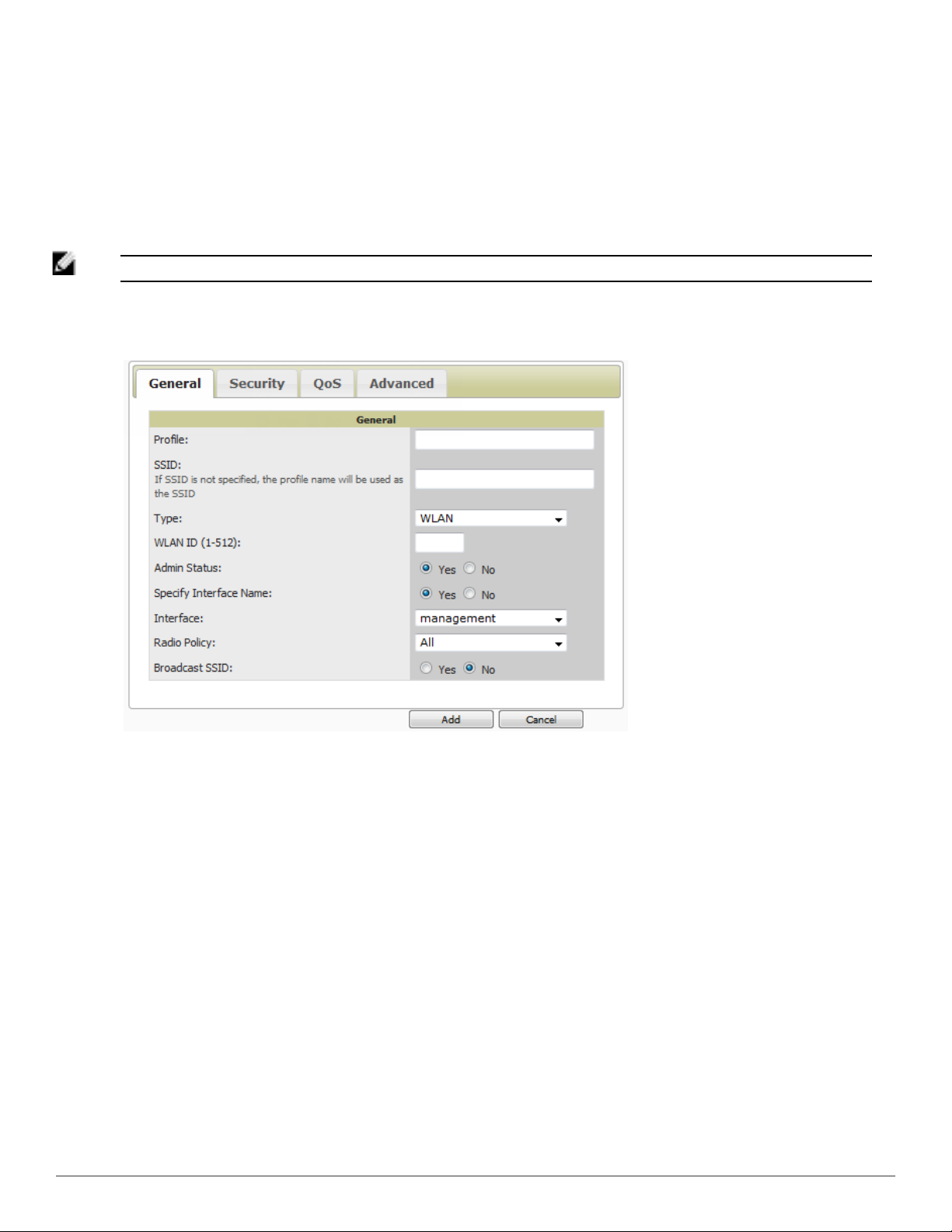
3. To add or edit SSIDs or VLANs that are dedicated to Cisco WLC devices, either select the Add button, or
select the pencil icon for an existing SSID/VLAN. A new page appears comprised of four tabs, as follows:
n General—Defines general administrative parameters for the Cisco WLC WLAN.
n Security—Defines encryption and RADIUS servers.
n QoS—Defines quality of service (QoS) parameters for the Cisco WLC WLAN.
n Advanced—Defines advanced settings that are available only with Cisco WLC devices, for example, AAA
override, coverage, DHCP and DTIM period.
NOTE: Refer to Cisco documentation for additional information about Cisco WLC devices and related features.
Figure 48: Groups > Cisco WLC Config > WLANs > Add New SSID/VLAN > General Tab Illustration
Dell PowerConnect W-AirWave 7.6 | User Guide Configuring and Using Device Groups | 83
Page 96

Figure 49: Groups > Cisco WLC Config > WLANs > Add New SSID/VLAN > Security Tab Illustration
Figure 50: Groups > Cisco WLC Config > WLANs > Add New SSID/VLAN > QoS Tab Illustration
84 | Configuring and Using Device Groups Del l PowerConnect W-Ai rWave 7.6 | User Guide
Page 97
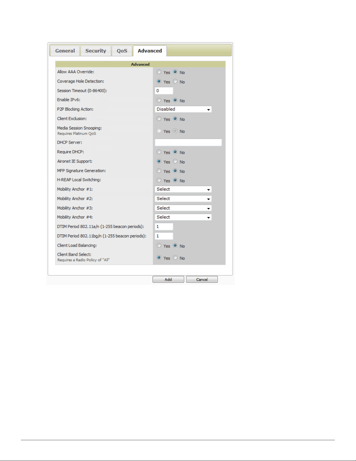
Figure 51: Groups > Cisco WLC Config > WLANs > Add New SSID/VLAN > Advanced Tab Illustration
Defining and Configuring LWAPP AP Groups for Cisco Devices
The Groups > Cisco WLC Config > WLANs > Advanced > AP Groups page allows you to add/edit/delete AP
Groups on the Cisco WLC. LWAPP AP Groups are used to limit the WLANs available on each AP. Cisco thin APs
are assigned to LWAPP AP Groups.
Viewing and Creating Cisco AP Groups
1. Go to the Groups > Cisco WLC Config page, and select WLANs > Advanced > AP Groups in the navigation
pane on the left side. This page displays the configured LWAPP APs. Figure 52 illustrates this page.
Dell PowerConnect W-AirWave 7.6 | User Guide Configuring and Using Device Groups | 85
Page 98
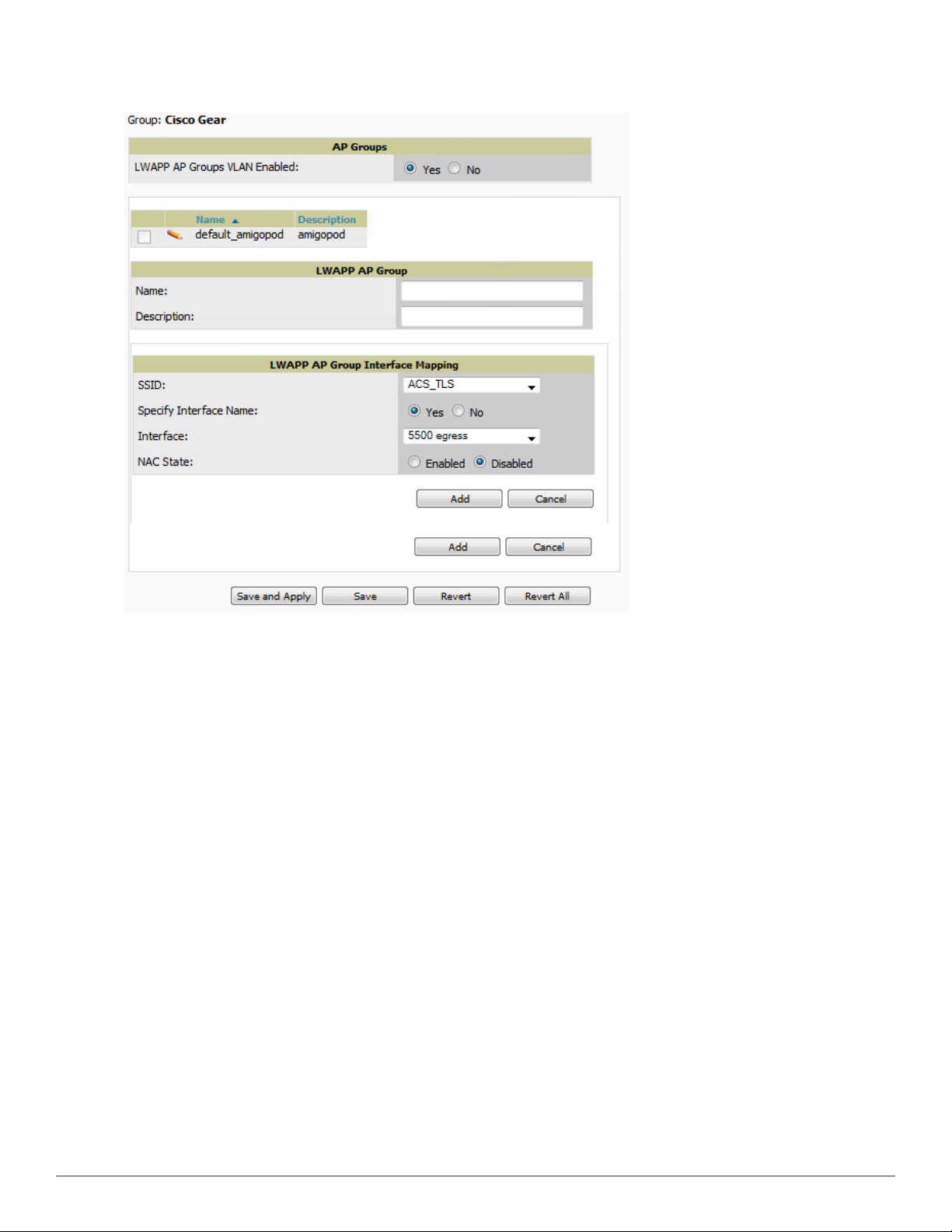
Figure 52: Groups > Cisco WLC Config > WLANS > Advanced > AP Groups Page Illustration
2. To add a new LWAPP AP group, select Yes in the AP Groups section. Additional controls appear.
3. Select Add to create a new LWAPP AP group. To edit an existing LWAPP AP group, select the pencil icon next
to that group. Add one or more SSIDs and the interface/VLAN ID mapping on the Add/Edit page of the
LWAPP AP Group.
4. Select Save and Apply to make these changes permanent, or select Save to retain these changes to be pushed to
controllers at a later time.
Configuring Cisco Controller Settings
The Groups > Cisco WLC Config > Controller page defines general Cisco WLC settings, Multicast settings,
Cisco mobility groups to be supported on Cisco controllers, Network Time Protocol (NTP), and Spanning Tree
Protocol settings.
Go to the Groups > Cisco WLC Config > Controller page. This navigation is illustrated in Figure 53.
86 | Configuring and Using Device Groups Del l PowerConnect W-Ai rWave 7.6 | User Guide
Page 99

Figure 53: Groups > Cisco WLC Config > Controller Navigation
Configuring Wireless Parameters for Cisco Controllers
This section illustrates the configuration of Wireless settings in support of Cisco WLC controllers. The navigation
for Wireless settings is illustrated in Figure 54.
Figure 54: Groups > Cisco WLC Config > Wireless Navigation Illustration
Configuring Cisco WLC Security Parameters and Functions
AirWave enables you to configure many security settings that are specific to Cisco WLC controllers. This section
supports four overriding types of configuration, as follows:
l AAA, to cover both RADIUS and TACACS+ server configuration
l Priority Order
l Wireless Protection Policies
l Web Auth
Dell PowerConnect W-AirWave 7.6 | User Guide Configuring and Using Device Groups | 87
Page 100

Figure 55 illustrates these components and this navigation:
Figure 55: Groups > Cisco WLC Config > Security Navigation Illustration
Configuring Management Settings for Cisco WLC
AirWave allows you to configure of SNMP and Syslog Server settings for Cisco WLC controllers. You can configure
up to four trap receivers on the Cisco WLC including the AMP IP that can be used in Global Groups. To define
SNMP and server settings, go to the Groups > Cisco WLC Config > Management page, illustrated in Figure 56.
Figure 56: Groups > Cisco WLC Config > Management Navigation Illustration
Configuring Group PTMP Settings
The Groups > PTMP configuration page configures Point-to-Multipoint (PTMP) for all subscriber and base
stations in the device group. Subscriber stations must be in the same group as all base stations with which they
might connect.
Perform the following steps to configure these functions.
1. Go to the Groups > List page and select the group for which to define PTMP settings by selecting the group
that supports Proxim MP.11. Alternatively, select Add from the Groups > List page to create a new group.
2. Select the Groups >PTMP tab. Figure 57 illustrates this page.
88 | Configuring and Using Device Groups Del l PowerConnect W-Ai rWave 7.6 | User Guide
 Loading...