

Page 1

Dell PowerConnect W-
AirWave 7.4
User Guide
Page 2

Copyright
© 2011 Aruba Networks, Inc. Aruba Networks trademarks include , Aruba Networks®, Aruba Wireless
Networks®, the registered Aruba the Mobile Edge Company logo, and Aruba Mobility Management System®. Dell™, the DELL™
logo, and PowerConnect™ are trademarks of Dell Inc.
All rights reserved. Specifications in this manual are subject to change without notice.
Originated in the USA. All other trademarks are the property of their respective owners.
Open Source Code
Certain Aruba products include Open Source software code developed by third parties, including software code subject to the GNU
General Public License (GPL), GNU Lesser General Public License (LGPL), or other Open Source Licenses. Includes software from
Litech Systems Design. This product includes software developed by Lars Fenneberg, et al. The Open Source code used can be
found at this site:
http://www.arubanetworks.com/open_source
Legal Notice
The use of Aruba Networks, Inc. switching platforms and software, by all individuals or corporations, to terminate other vendors’
VPN client devices constitutes complete acceptance of liability by that individual or corporation for this action and indemnifies, in
full, Aruba Networks, Inc. from any and all legal actions that might be taken against it with respect to infringement of copyright on
behalf of those vendors.
Dell PowerConnect W-AirWave 7.4 | User Guide 0510897-09 | December 2011
Page 3

Contents
Preface..................................................................................................................................................................... 11
Document Organization...................................................................................................................11
Note, Caution, and Warning Icons ................................................................................................12
Contacting Support ..........................................................................................................................12
Chapter 1 Introduction........................................................................................................................ 13
AirWave—A Unified Wireless Network Command Center.......................................................13
AirWave Management Platform ............................................................................................ 13
Dell PowerConnect W Configuration.................................................................................... 14
VisualRF...................................................................................................................................... 14
RAPIDS.......................................................................................................................................14
Master Console and Failover..................................................................................................15
Integrating AirWave into the Network and Organizational Hierarchy .................................... 15
Chapter 2 Installing and Getting Started ......................................................................................... 17
AirWave Hardware Requirements and Installation Media ....................................................... 17
Supported Browsers........................................................................................................................17
Installing Linux CentOS 5 (Phase 1)...............................................................................................18
Installing AirWave Software (Phase 2)......................................................................................... 18
Getting Started..........................................................................................................................18
Step 1: Configuring Date and Time, Checking for Prior Installations ..............................18
Date and Time...................................................................................................................18
Previous AirWave Installations .....................................................................................19
Step 2: Installing AirWave Software ..................................................................................... 19
Step 3: Checking the AirWave Installation...........................................................................19
Step 4: Assigning an IP Address to the AirWave System..................................................19
Step 5: Naming the AirWave Network Administration System ........................................20
Step 6: Assigning a Host Name to AirWave.........................................................................20
Step 7: Changing the Default Root Password...................................................................... 20
Completing the Installation ..................................................................................................... 21
Configuring and Mapping Port Usage for AirWave....................................................................21
AirWave Navigation Basics............................................................................................................ 22
Status Section...........................................................................................................................22
Navigation Section...................................................................................................................23
Activity Section.........................................................................................................................25
Help Links in the UI...................................................................................................................25
Common List Settings ..............................................................................................................25
Buttons and Icons ....................................................................................................................26
Getting Started with AirWave ........................................................................................................28
Chapter 3 Configuring AMP ............................................................................................................... 29
Before You Begin.............................................................................................................................. 29
Formatting the Top Header ............................................................................................................. 29
Customizing Columns in Lists .........................................................................................................30
Resetting Pagination Records........................................................................................................31
Using the Pagination Widget..........................................................................................................31
Dell PowerConnect W-AirWave 7.4 | User Guide Contents | 3
Page 4

Using Export CSV for Lists and Reports........................................................................................31
Defining Graph Display Preferences............................................................................................. 32
Customizing the Dashboard............................................................................................................32
Customized Search ..........................................................................................................................34
Setting Severe Alert Warning Behavior ....................................................................................... 34
Defining General AirWave Server Settings .................................................................................35
Defining AirWave Network Settings ............................................................................................. 43
Creating AirWave Users.................................................................................................................. 44
Creating AirWave User Roles......................................................................................................... 46
Configuring Login Message, TACACS+ and RADIUS Authentication...................................... 48
Setting Up Login Configuration Options................................................................................48
Setting up Single Sign-On ....................................................................................................... 49
Configuring TACACS+ Authentication ..................................................................................49
Configuring RADIUS Authentication and Authorization ....................................................50
Integrating a RADIUS Accounting Server............................................................................ 51
Enabling AirWave to Manage Your Devices................................................................................ 52
Configuring Communication Settings for Discovered Devices.........................................53
Loading Device Firmware Onto AirWave (optional)........................................................... 55
Overview of the Device Setup > Upload Firmware & Files Page ............................. 55
Loading Firmware Files to AirWave .............................................................................. 56
Using Web Auth Bundles in AirWave...........................................................................57
Setting Up Device Types ................................................................................................................. 58
Configuring Cisco WLSE and WLSE Rogue Scanning................................................................ 58
Introduction to Cisco WLSE.................................................................................................... 58
Configuring WLSE Initially in AirWave..................................................................................59
Adding an ACS Server for WLSE ................................................................................... 59
Enabling Rogue Alerts for Cisco WLSE ........................................................................59
Configuring WLSE to Communicate with APs ............................................................. 59
Discovering Devices........................................................................................................60
Managing Devices ........................................................................................................... 60
Inventory Reporting .........................................................................................................60
Defining Access ...............................................................................................................60
Grouping ............................................................................................................................60
Configuring IOS APs for WDS Participation ........................................................................60
WDS Participation............................................................................................................ 61
Primary or Secondary WDS ...........................................................................................61
Configuring ACS for WDS Authentication............................................................................ 61
Configuring Cisco WLSE Rogue Scanning........................................................................... 62
Configuring ACS Servers................................................................................................................. 63
Integrating AirWave with an Existing Network Management Solution (NMS) .....................64
Auditing PCI Compliance on the Network....................................................................................65
Introduction to PCI Requirements .........................................................................................65
PCI Auditing in the AirWave Interface..................................................................................65
Enabling or Disabling PCI Auditing........................................................................................ 66
Deploying WMS Offload..................................................................................................................67
Overview of WMS Offload in AirWave .................................................................................67
General Configuration Tasks Supporting WMS Offload in AirWave............................... 68
Additional Information Supporting WMS Offload............................................................... 68
Chapter 4 Configuring and Using Device Groups in AirWave...................................................... 69
AirWave Groups Overview .............................................................................................................70
Viewing All Defined Device Groups ......................................................................................71
Configuring Basic Group Settings .................................................................................................72
4 | Contents Dell PowerConnect W-AirWave 7.4 | User Guide
Page 5

Adding and Configuring Group AAA Servers............................................................................... 80
Configuring Group Security Settings............................................................................................. 81
Configuring Group SSIDs and VLANs ...........................................................................................83
Configuring Radio Settings for Device Groups............................................................................87
Cisco WLC Group Configuration ....................................................................................................91
Accessing Cisco WLC Configuration ....................................................................................91
Navigating Cisco WLC Configuration.................................................................................... 91
Configuring WLANs for Cisco WLC Devices........................................................................92
Defining and Configuring LWAPP AP Groups for Cisco Devices..................................... 94
Viewing and Creating Cisco AP Groups ...............................................................................94
Configuring Cisco Controller Settings................................................................................... 94
Configuring Wireless Parameters for Cisco Controllers....................................................95
Configuring Cisco WLC Security Parameters and Functions............................................95
Configuring Management Settings for Cisco WLC ............................................................ 95
Configuring Group PTMP Settings................................................................................................. 96
Configuring Proxim Mesh Radio Settings..................................................................................... 97
Configuring Group MAC Access Control Lists............................................................................. 98
Specifying Minimum Firmware Versions for APs in a Group....................................................98
Comparing Device Groups .............................................................................................................. 99
Deleting a Group.............................................................................................................................100
Changing Multiple Group Configurations ................................................................................... 100
Modifying Multiple Devices..........................................................................................................101
Using Global Groups for Group Configuration ........................................................................... 104
Chapter 5 Discovering, Adding, and Managing Devices ............................................................ 107
Device Discovery Overview.......................................................................................................... 107
Discovering and Adding Devices................................................................................................. 107
SNMP/HTTP Scanning ..........................................................................................................108
Adding Networks for SNMP/HTTP Scanning............................................................108
Adding Credentials for Scanning................................................................................. 108
Defining a Scan Set .......................................................................................................109
Running a Scan Set........................................................................................................ 110
Enabling Cisco Discovery Protocol (CDP).......................................................................... 111
Authorizing Devices to AirWave from APs/Devices > New Page..................................111
Manually Adding Individual Devices...................................................................................112
Adding Devices with the Device Setup > Add Page ................................................112
Adding Multiple Devices from a CSV File................................................................... 114
Adding Universal Devices............................................................................................. 115
Assigning Devices to the Ignored Page .............................................................................116
Monitoring Devices........................................................................................................................116
Viewing Device Monitoring Statistics.................................................................................117
Understanding the APs/Devices > Monitor Pages for All Device Types...................... 118
Monitoring Data Specific to Wireless Devices................................................................. 118
Evaluating Radio Statistics for an AP..................................................................................124
Overview of the Radio Statistics Page .......................................................................124
Viewing Real-Time ARM Statistics .............................................................................124
Issues Summary section...............................................................................................125
802.11 Radio Counters Summary .................................................................................125
Radio Statistics Interactive Graphs ............................................................................126
Recent ARM Events Log................................................................................................ 127
Detected Interfering Devices Table............................................................................128
Active BSSIDs Table...................................................................................................... 128
Monitoring Data for Mesh Devices ..................................................................................... 128
Monitoring Data for Wired Devices (Routers and Switches) .........................................130
Dell PowerConnect W-AirWave 7.4 | User Guide Contents | 5
Page 6

Understanding the APs/Devices > Interfaces Page......................................................... 132
Auditing Device Configuration .............................................................................................133
Using Device Folders (Optional)...........................................................................................134
Configuring and Managing Devices............................................................................................134
Moving a Device from Monitor Only to Manage Read/Write Mode.............................. 135
Configuring AP Settings ........................................................................................................135
Setting a Maintenance Window for a Device ...................................................................141
Configuring Device Interfaces for Switches......................................................................141
Individual Device Support and Firmware Upgrades.........................................................144
Troubleshooting a Newly Discovered Down Device................................................................ 146
Setting up Dell Spectrum Analysis in AirWave ......................................................................... 147
Spectrum Configurations and Prerequisites......................................................................147
Setting up a Permanent Spectrum Dell AP Group............................................................ 148
Configuring an Individual AP to run in Spectrum Mode ..................................................148
Configuring a Controller to use the Spectrum Profile ......................................................149
Chapter 6 Creating and Using Templates ...................................................................................... 151
Group Templates ............................................................................................................................151
Supported Device Templates ............................................................................................... 151
Template Variables ................................................................................................................151
Viewing and Adding Templates ...................................................................................................152
Configuring General Template Files and Variables ..................................................................155
Configuring General Templates ...........................................................................................156
IOS Configuration File Template .................................................................................. 157
Device Configuration File on APs/Devices > Audit Configuration Page ............... 157
Using Template Syntax..........................................................................................................157
Using Directives to Eliminate Reporting of Configuration Mismatches........................ 157
Ignore_and_do_not_push Command .........................................................................158
Push_and_exclude Command .....................................................................................158
Using Conditional Variables in Templates..........................................................................158
Using Substitution Variables in Templates ........................................................................159
Using AP-Specific Variables ................................................................................................160
Configuring Cisco IOS Templates ................................................................................................ 160
Applying Startup-config Files ............................................................................................... 161
WDS Settings in Templates .................................................................................................. 161
SCP Required Settings in Templates...................................................................................161
Supporting Multiple Radio Types via a Single IOS Template..........................................162
Configuring Single and Dual-Radio APs via a Single IOS Template..............................162
Configuring Cisco Catalyst Switch Templates........................................................................... 162
Configuring Symbol Controller / HP WESM Templates............................................................ 163
Configuring a Global Template.....................................................................................................165
Chapter 7 Using RAPIDS and Rogue Classification..................................................................... 167
Introduction to RAPIDS .................................................................................................................167
Viewing Overall Network Health on RAPIDS > Overview........................................................ 168
Setting Up RAPIDS ......................................................................................................................... 169
Basic Configuration................................................................................................................169
Rogue Containment Options ................................................................................................. 171
Additional Settings ................................................................................................................. 172
Defining RAPIDS Rules..................................................................................................................172
Controller Classification with WMS Offload...................................................................... 172
Device OUI Score ................................................................................................................... 173
Rogue Device Threat Level...................................................................................................173
Viewing and Configuring RAPIDS Rules............................................................................. 174
6 | Contents Dell PowerConnect W-AirWave 7.4 | User Guide
Page 7

Deleting or Editing a Rule.............................................................................................. 176
Recommended RAPIDS Rules.............................................................................................. 176
Using RAPIDS Rules with Additional AirWave Functions ...............................................176
Viewing Rogues on the RAPIDS > List Page..............................................................................176
Overview of the RAPIDS > Detail Page....................................................................................... 179
Viewing Ignored Rogue Devices..........................................................................................180
Using RAPIDS Workflow to Process Rogue Devices....................................................... 180
Score Override................................................................................................................................180
Using the Audit Log ........................................................................................................................ 181
Additional Resources..................................................................................................................... 182
Chapter 8 Performing Daily Administration in AirWave.............................................................. 183
Monitoring and Supporting AirWave with the System Pages ................................................ 183
Using the System > Status Page.......................................................................................... 184
Viewing Device Events in System > Syslog & Traps........................................................ 185
Using the System > Event Log Page.................................................................................... 186
Viewing, Delivering and Responding to Triggers and Alerts ..........................................187
Viewing Triggers.....................................................................................................................187
Creating New Triggers ..........................................................................................................187
Setting Triggers for Devices......................................................................................... 190
Setting Triggers for Interfaces and Radios................................................................ 191
Setting Triggers for Discovery ..................................................................................... 191
Setting Triggers for Clients...........................................................................................192
Setting Triggers for RADIUS Authentication Issues ................................................193
Setting Triggers for IDS Events.................................................................................... 193
Setting Triggers for AirWave Health........................................................................... 194
Delivering Triggered Alerts...................................................................................................194
Viewing Alerts.........................................................................................................................194
Responding to Alerts..............................................................................................................195
Monitoring and Supporting WLAN Clients.................................................................................196
Overview of the Clients Pages .............................................................................................196
Monitoring WLAN Users in the Clients > Connected and Clients > All Pages............. 197
Supporting Guest WLAN Users With the Clients > Guest Users Page .........................199
Supporting VPN Users with the Clients > VPN Sessions Page ......................................201
Supporting RFID Tags With the Clients > Tags Page .......................................................202
Evaluating and Diagnosing User Status and Issues.................................................................203
Evaluating User Status with the Clients > Client Detail Page .........................................203
Mobile Device Access Control ....................................................................................204
Classifying Dell Devices in Client Detail.....................................................................205
Quick Links for Clients on Dell Devices ...................................................................... 206
Using the Deauthenticate Client Feature ................................................................... 206
Viewing a Client’s Association History.......................................................................206
Viewing the Rogue Association History for a Client................................................. 206
Evaluating Client Status with the Clients > Diagnostics Page........................................ 207
Managing Mobile Devices with SOTI MobiControl and AirWave.......................................... 207
Overview of SOTI MobiControl.............................................................................................207
Prerequisites for Using MobiControl with AirWave......................................................... 207
Adding a Mobile Device Management Server for MobiControl..................................... 208
Accessing MobiControl from the Clients > Client Detail Page .......................................208
Monitoring and Supporting AirWave with the Home Pages...................................................209
Monitoring AirWave with the Home > Overview Page.................................................... 210
Viewing and Updating License Information....................................................................... 211
Searching AirWave with the Home > Search Page .........................................................213
Accessing AirWave Documentation................................................................................... 214
Configuring Your Own User Information with the Home > User Info Page ..................214
Using the System > Configuration Change Jobs Page.....................................................216
Dell PowerConnect W-AirWave 7.4 | User Guide Contents | 7
Page 8

Using the System > Firmware Upgrade Jobs Page.......................................................... 216
Using the System > Performance Page.............................................................................. 217
Supporting AirWave Servers with the Master Console........................................................... 221
Using the Public Portal on Master Console....................................................................... 221
Adding a Managed AMP with the Master Console.......................................................... 222
Using Global Groups with Master Console ........................................................................ 223
Upgrading AirWave........................................................................................................................ 223
Upgrade Instructions ............................................................................................................. 223
Backing Up AirWave...................................................................................................................... 224
Viewing and Downloading Backups ...................................................................................224
Running Backup on Demand ................................................................................................ 224
Restoring from a Backup.......................................................................................................224
Using AirWave Failover for Backup ............................................................................................ 225
Navigation Section of AirWave Failover ............................................................................225
Adding Watched AirWave Stations ....................................................................................225
Logging out of AirWave.................................................................................................................226
Chapter 9 Creating, Running, and Emailing Reports.................................................................... 227
Overview of AirWave Reports......................................................................................................227
Reports > Definitions Page Overview .................................................................................227
Reports > Generated Page Overview..................................................................................229
Using Daily Reports........................................................................................................................230
Viewing Generated Reports..................................................................................................230
Using Custom Reports ...........................................................................................................231
Using the Dell License Report .............................................................................................. 232
Using the Capacity Planning Report....................................................................................232
Using the Configuration Audit Report .................................................................................234
Using the Device Summary Report......................................................................................236
Using the Device Uptime Report.......................................................................................... 237
Using the IDS Events Report.................................................................................................239
Using the Inventory Report ................................................................................................... 239
Using the Memory and CPU Utilization Report.................................................................. 241
Using the Network Usage Report ........................................................................................ 241
Using the New Rogue Devices Report................................................................................242
Using the New Users Report ................................................................................................ 245
Using the PCI Compliance Report........................................................................................245
Using the Port Usage Report ................................................................................................ 246
Using the RADIUS Authentication Issues Report .............................................................246
Using the RF Health Report ................................................................................................... 247
Using the Rogue Clients Report ...........................................................................................249
Using the Rogue Containment Audit Report ......................................................................250
Using the Client Session Report...........................................................................................250
Defining Reports ............................................................................................................................. 252
Emailing and Exporting Reports ................................................................................................... 255
Emailing Reports in General Email Applications............................................................... 255
Emailing Reports to Smarthost............................................................................................. 255
Exporting Reports to XML or CSV ........................................................................................ 255
Transferring Reports Using FTP........................................................................................... 255
Chapter 10 Using VisualRF ................................................................................................................. 257
Features ...........................................................................................................................................258
Useful Terms ...................................................................................................................................258
Starting VisualRF ............................................................................................................................258
Basic QuickView Navigation ........................................................................................................ 259
Network View Navigation ..................................................................................................... 260
8 | Contents Dell PowerConnect W-AirWave 7.4 | User Guide
Page 9

Overlays ...........................................................................................................................260
Display Menu ..................................................................................................................260
Edit Menu......................................................................................................................... 261
Using the Settings in the VisualRF > Setup Page......................................................................262
VisualRF Resource Utilization...............................................................................................265
Configuring QuickView Personal Preferences..........................................................................266
Increasing Location Accuracy.....................................................................................................267
Adding Exterior Walls ............................................................................................................ 268
Location Training for Stationary Devices........................................................................... 268
Adding Client Surveys............................................................................................................269
Adding Location Probability Regions .................................................................................. 270
Adding an IDF..........................................................................................................................271
Viewing Port Status on Deployed Switches ......................................................................272
Fine-Tuning Location Service in VisualRF > Setup........................................................... 272
Configuring Infrastructure ............................................................................................ 273
Deploying APs for Client Location Accuracy ............................................................274
Using QuickView to Assess RF Environments ........................................................................... 274
Viewing a Wireless User's RF Environment....................................................................... 274
Tracking Location History.............................................................................................275
Checking Signal Strength to Client Location ............................................................. 276
Viewing an AP’s Wireless RF Environment........................................................................ 276
Viewing a Floor Plan’s RF Environment ..............................................................................277
Viewing a Network, Campus, Building’s RF Environment................................................278
Viewing Campuses, Buildings, or Floors from a Tree View.............................................278
Planning and Provisioning ............................................................................................................279
Creating a New Campus........................................................................................................279
Creating a New Building in a Campus ................................................................................280
Importing a Floor Plan............................................................................................................281
Editing a Floor Plan Image ....................................................................................................282
Cropping the Floor Plan Image..................................................................................... 282
Sizing a Non-CAD Floor Plan........................................................................................283
Removing Color from a Floor Plan Image...................................................................283
Assigning Campus, Building and Floor Numbers...................................................... 284
Assigning Optional Planner, Owner, or Installer Information for the Floor Plan . 284
Controlling the Layers in the Uploaded Floor Plan (CAD only) ...............................284
Error Checking of CAD Images ....................................................................................284
Last Steps in Editing an Uploaded Image................................................................... 285
Provisioning Existing Access Points onto the Floor Plan ................................................285
Automatically Provisioning APs onto a Floor Plan............................................................286
Tweaking a Planning Region ................................................................................................ 287
Auto-Matching Planned Devices.........................................................................................288
Printing a Bill of Materials Report .......................................................................................288
Importing and Exporting in VisualRF ...........................................................................................289
Exporting a campus................................................................................................................289
Importing from CAD................................................................................................................289
Batch Importing CAD Files....................................................................................................290
Requirements..................................................................................................................290
Pre Processing Steps .................................................................................................... 290
Upload Processing Steps.............................................................................................. 290
Post Processing Steps ..................................................................................................291
Sample Upload Instruction XML File........................................................................... 291
Common Importation Problems ...................................................................................291
Importing from a Dell PowerConnect W-Series Controller............................................. 291
Pre-Conversion Checklist .............................................................................................291
Process on Controller....................................................................................................291
Process on AMP............................................................................................................. 292
Dell PowerConnect W-AirWave 7.4 | User Guide Contents | 9
Page 10

VisualRF Location APIs.................................................................................................................. 292
Sample Device Location Response..................................................................................... 292
Sample Site Inventory Response......................................................................................... 292
About VisualRF Plan.......................................................................................................................293
Overview .................................................................................................................................. 293
Minimum requirements .........................................................................................................293
Installation ............................................................................................................................... 293
Differences between VisualRF Plan and VisualRF online................................................294
Appendix A Setting Up Dell PowerConnect W-Instant in AirWave ............................................. 295
Overview of Dell PowerConnect W-Instant...............................................................................295
Using Dell PowerConnect W-Instant with AMP .......................................................................295
Workflow of the Dell PowerConnect W-Instant and AMP Integration Process .................296
Setting up Dell PowerConnect W-Instant Hardware....................................................... 296
Required Personnel................................................................................................................296
Creating your Organization String .......................................................................................296
The Shared Secret Key..........................................................................................................297
Entering the Organization String and AirWave Information into the IAP .....................297
Receiving the Virtual Controller as a New Device in AMP .............................................298
Verifying the Shared Secret and Adding the Device........................................................298
Remaining Manual Admin Tasks in AMP ........................................................................... 299
AMP Pages with Instant-Specific Features............................................................................... 299
Other Available Features............................................................................................................... 300
Firmware Image Management............................................................................................. 300
Intrusion Detection System ..................................................................................................300
Known Issues of Dell PowerConnect W-Instant Integration with AirWave ........................300
Appendix B Installing AirWave on VMware ESX 4.1 ...................................................................... 301
Creating a New Virtual Machine to Run AirWave .................................................................... 301
Installing AirWave on the Virtual Machine................................................................................301
AirWave Post-Installation Issues on VMware .......................................................................... 302
Index....................................................................................................................................................................... 303
10 | Contents Dell PowerConnect W-AirWave 7.4 | User Guide
Page 11

Preface
This preface provides an overview of this user guide and contact information for Dell in the following sections:
“Document Organization” on page11
“Note, Caution, and Warning Icons” on page12
“Contacting Support” on page12
Document Organization
This user guide includes instructions and examples of the graphical user interface (UI) for installation,
configuration, and daily operation of the Dell PowerConnect W-AirWave 7.4. This includes wide deployment of
wireless access points (APs), device administration, rogue detection and classification, wireless controller devices,
security, reports, and additional features of AirWave.
Table 1 Document Organization and Purposes
Chapter Description
Chapter 1, “Introduction” Introduces and presents AirWave, its components, and general network functions.
Chapter 2, “Installing and Getting
Started”
Chapter 3, “Configuring AMP” Describes the primary and required configurations for startup and launch of AirWave,
Chapter 4, “Configuring and Using
Device Groups in AirWave”
Chapter 5, “Discovering, Adding,
and Managing Devices”
Chapter 6, “Creating and Using
Templates”
Chapter 7, “Using RAPIDS and
Rogue Classification”
Chapter 8, “Performing Daily
Administration in AirWave”
Chapter 9, “Creating, Running, and
Emailing Reports”
Chapter 10, “Using VisualRF” Describes how to use VisualRF.
Describes system and network requirements, Linux OS installation, and AirWave
installation.
with frequently used optional configurations.
Describes configuration and deployment for group device profiles.
Describes how to discover and manage devices on the network.
Describes and illustrates the use of templates in group and global device configuration.
Describes RAPIDS module of AirWave, and enhanced rogue classification supported in
AirWave.
Describes common daily operations and tools in AirWave, to include general user
administration, the use of triggers and alerts, network monitoring, and backups.
Describes AirWave reports, scheduling and generation options, and distribution of
reports from AirWave.
Appendix A, “Setting Up Dell
PowerConnect W-Instant in
AirWave” on page 295
Appendix B, “Installing AirWave on
VMware ESX 4.1” on page 301
Index Provides extensive citation of and links to document topics, with emphasis on the
Dell PowerConnect W-AirWave 7.4 | User Guide Preface | 11
Ddescribes the Dell PowerConnect W-Instant access point and Virtual Controller system,
and how to integrate this system with AMP.
Provides instructions for an alternative installation option on VMware ESX for
AirWave UI and tasks relating to AirWave installation and operation.
Page 12

Note, Caution, and Warning Icons
This document uses the following note, caution, and warning icons to emphasize advisories for certain actions,
configurations, or concepts:
NOTE: Indicates helpful suggestions, pertinent information, and important things to remember.
CAUTION: Indicates a risk of damage to your hardware or loss of data.
WARNING: Indicates a risk of personal injury or death.
Contacting Support
Table 2 Web Support
Web Support
Main Website dell.com
Support Website support.dell.com
Documentation Website support.dell.com/manuals
12 | Preface Dell PowerConnect W-AirWave 7.4 | User Guide
Page 13

Chapter 1
Introduction
Thank you for choosing Dell PowerConnect W-AirWave. AirWave makes it easy and efficient to manage your
wireless network by combining industry-leading functionality with an intuitive user interface, enabling network
administrators and helpdesk staff to support and control even the largest wireless networks in the world.
This User Guide provides instructions for the installation, configuration, and operation of AirWave. This chapter
includes the following topics:
“AirWave—A Unified Wireless Network Command Center” on page13
“Integrating AirWave into the Network and Organizational Hierarchy” on page15
If you have any questions or comments, please contact Dell support at support.dell.com.
AirWave—A Unified Wireless Network Command Center
Dell PowerConnect W-AirWave is the only network management software that offers you a single intelligent
console from which to monitor, analyze, and configure wireless networks in automatic fashion. Whether your
wireless network is simple or a large, complex, multi-vendor installation, AirWave manages it all.
AirWave supports hardware from leading wireless vendors including Dell PowerConnect W-Series, Aruba
Networks, Avaya, Cisco (Aironet and WLC), Enterasys, Juniper Networks, LANCOM Systems, Meru, Nortel,
ProCurve by HP, Proxim, Symbol, Trapeze, Tropos, and many others.
The components of the AirWave are detailed below:
AirWave Management Platform
The AirWave Management Platform (AMP) is the centerpiece of Dell PowerConnect W-AirWave, offering the
following functions and benefits:
Core network management functionality:
Network discovery
Configuration of APs & controllers
Automated compliance audits
Firmware distribution
Monitoring of every device and user connected to the network
Real-time and historical trend reports
Granular administrative access
Role-based (for example, Administrator contrasted with Help Desk)
Network segment (for example, “Retail Store” network contrasted with “Corporate HQ” network)
Flexible device support
Thin, thick, mesh network architecture
Multi-vendor support
Current and legacy hardware support
Dell PowerConnect W-AirWave 7.4 | User Guide Introduction | 13
Page 14

Dell PowerConnect W Configuration
AirWave supports global and group-level configuration of Dell PowerConnect W-Series ArubaOS (AOS), the
operating system, software suite, and application engine that operates Dell PowerConnect W mobility and
centralizes control over the entire mobile environment. For a complete description of ArubaOS, refer to the Dell
PowerConnect W-Series ArubaOS User Guide at support.dell.com/manuals.
AirWave consolidates and pushes global Dell PowerConnect W-Series configurations from within AirWave.
Two pages in AirWave support Dell PowerConnect W Configuration:
Device Setup > Dell PowerConnect W Configuration for global Dell PowerConnect W Configuration
Groups > Dell PowerConnect W Config for group-level Dell PowerConnect W Configuration
For additional information that includes a comprehensive inventory of all pages and settings that support Dell
PowerConnect W Configuration, refer to the Dell PowerConnect W-AirWave 7.4 Configuration Guide at
support.dell.com/manuals.
VisualRF
VisualRF is a powerful tool for monitoring and managing radio frequency (RF) dynamics within your wireless
network, to include the following functions and benefits:
Accurate location information for all wireless users and devices
Up-to-date heat maps and channel maps for RF diagnostics
Adjusts for building materials.
Supports multiple antenna types.
Floor plan, building, and campus views
Visual display of errors and alerts
Easy import of existing floor plans and building maps
Planning of new floor plans and AP placement recommendations
RAPIDS
RAPIDS is a powerful and easy-to-use tool for monitoring and managing security on your wireless network, to
include the following features and benefits:
Automatic detection of unauthorized wireless devices
Rogue device classification that supports multiple methods of rogue detection
Wireless detection:
Uses authorized wireless APs to report other devices within range.
Calculates and displays rogue location on VisualRF map.
Wired network detection:
Discovers rogue APs located beyond the range of authorized APs/sensors.
Queries routers and switches.
Ranks devices according to the likelihood they are rogues.
Multiple tests to eliminate false positive results.
Provides rogue discovery that identifies the switch and port to which a rogue device is connected.
14 | Introduction Dell PowerConnect W-AirWave 7.4 | User Guide
Page 15

Master Console and Failover
The Dell PowerConnect W-AirWave Master Console and Failover tools enable network-wide information in
easy-to-understand presentation, to entail operational information and high-availability for failover scenarios.
The benefits of these tools include the following:
Provides network-wide visibility, even when the WLAN grows to 50,000+ devices
Executive Portal allows executives to view high-level usage and performance data
Aggregated alerts
Failover
Many-to-one failover
One-to-one failover
The Master Console and Failover servers can be configured with a Device Down trigger that generates an alert if
communication is lost. In addition to generating an alert, the Master Console or Failover server can also send
email or NMS notifications about the event.
Integrating AirWave into the Network and Organizational Hierarchy
Dell PowerConnect W-AirWave generally resides in the NOC and communicates with various components of
your WLAN infrastructure. In basic deployments, AirWave communicates solely with indoor wireless access
points (and WLAN controllers over the wired network. In more complex deployments, AirWave seamlessly
integrates and communicates with authentication servers, accounting servers, TACACS+ servers, routers,
switches, network management servers, wireless IDS solutions, helpdesk systems, indoor wireless access points,
mesh devices. AirWave has the flexibility to manage devices on local networks, remote networks, and networks
using Network Address Translation (NAT). AirWave communicates over-the-air or over-the-wire using a variety
of protocols.
The power, performance, and usability of AirWave become more apparent when considering the diverse
components within a WLAN. Table 3 itemizes some example network components.
Table 3 Components of a WLAN
Component Description
Autonomous AP Standalone device which performs radio and authentication functions
Thin AP Radio-only device coupled with WLAN controller to perform authentication
WLAN controller Used in conjunction with thin APs to coordinate authentication and roaming
NMS Network Management Systems and Event Correlation (OpenView, Tivoli, and so forth)
RADIUS Authentication RADIUS authentication servers (Funk, FreeRADIUS, ACS, or IAS)
RADIUS Accounting AirWave itself serves as a RADIUS accounting client
Wireless Gateways Provide HTML redirect and/or wireless VPNs
TACACS+ Used to authenticate AirWave administrative users
Routers/Switches Provide AirWave with data for user information and AP and Rogue discovery
Help Desk Systems Remedy EPICOR
Rogue APs Unauthorized APs not registered in the AirWave database of managed APs
The flexibility of AirWave enables it to integrate seamlessly into your business hierarchy as well as your network
topology. AirWave facilitates various administrative roles to match each individual user's role and responsibility:
A Help Desk user may be given read-only access to monitoring data without being permitted to make
configuration changes.
Dell PowerConnect W-AirWave 7.4 | User Guide Introduction | 15
Page 16

A U.S.-based network engineer may be given read-write access to manage device configurations in North
America, but not to control devices in the rest of the world.
A security auditor may be given read-write access to configure security policies across the entire WLAN.
NOC personnel may be given read-only access to monitoring all devices from the Master Console.
16 | Introduction Dell PowerConnect W-AirWave 7.4 | User Guide
Page 17

Chapter 2
Installing and Getting Started
This chapter contains information and procedures for installing and launching Dell PowerConnectW-AirWave,
and includes the following topics:
“AirWave Hardware Requirements and Installation Media” on page17
“Supported Browsers” on page17
“Installing Linux CentOS 5 (Phase 1)” on page18
“Installing AirWave Software (Phase 2)” on page18
“Configuring and Mapping Port Usage for AirWave” on page21
“AirWave Navigation Basics” on page22
“Getting Started with AirWave” on page28
NOTE: AirWave does not support downgrading to older versions. Significant data could be lost or compromised in such a
downgrade. In unusual circumstances requiring that you return to an earlier version of AirWave, we recommend you perform a
fresh installation of the earlier AirWave version, and then restore data from a pre-upgrade backup.
AirWave Hardware Requirements and Installation Media
The AirWave installation CD includes all software (including the Linux OS) required to complete the
installation of AirWave. AirWave supports any hardware that is Red Hat Enterprise Linux 5 certified. By default,
all installs are based on a 64-bit operating system.
AirWave hardware requirements vary by version. As additional features are added to AirWave, increased hardware
resources become necessary. For the most recent hardware requirements, refer to the Dell PowerConnect W
Server Sizing Guide at support.dell.com/manuals.
AirWave is intended to operate as a soft appliance. Other applications should not run on the same installation.
Additionally, local shell users can access data on AirWave, so it is important to restrict access to the shell only to
authorized users.
You can create sudo users in place of root for companies that don't allow root logins.
Supported Browsers
Windows (XP, Vista, Windows 7)
Internet Explorer 7/8/9
Firefox 3.x
Google Chrome 9.x (stable)
Mac (OS X, 10.5, 10.6)
Safari 4.x and higher,
Firefox 3.x
Google Chrome 9.x
Dell PowerConnect W-AirWave 7.4 | User Guide Installing and Getting Started | 17
Page 18

Installing Linux CentOS 5 (Phase 1)
Perform the following steps to install the Linux CentOS 5 operating system. The Linux installation is a
prerequisite to installing AirWave on the network management system.
CAUTION: This procedure erases the hard drive(s) on the server.
1. Insert the AirWave installation CD-ROM into the drive and boot the server.
2. If this is a new installation of the AirWave software, type install and press Enter.
To configure the partitions manually, type expert and press Enter.
The following message appears on the screen:
Welcome to AirWave Installer Phase I
- To install a new AMP, type install <ENTER>.
WARNING: This will ERASE all data on your hard drive.
- To install AirWave and manually configure hard drive settings, type expert <ENTER>.
boot:
3. Allow the installation process to continue. Installing the CentOS software (Phase I) takes 10 to 20 minutes to
complete. This process formats the hard drive and launches Anaconda to install all necessary packages.
Anaconda gauges the progress of the installation.
Upon completion, the system will prompt you to eject the installation CD and reboot the system.
4. Remove the CD from the drive and store in a safe location.
Installing AirWave Software (Phase 2)
Getting Started
After the reboot, the GRUB screen appears.
1. Press Enter or wait six seconds, and the system automatically loads the kernel.
2. When the kernel is loaded, log into the server using the following credentials:
login = root
password = admin
3. Start the AirWave software installation script by executing the./amp-install command.
Type./amp-install at the command prompt and press Enter to execute the script.
Step 1: Configuring Date and Time, Checking for Prior Installations
Date and Time
The following message appears, and this step ensures the proper date and time are set on the server.
------------------------ Date and Time Configuration -----------------Current Time: Fri Nov 21 09:18:12 PST 2008
1) Change Date and Time
2) Change Time Zone
0) Finish
Ensure that you enter the accurate date and time during this process. Errors will arise later in the installation if
the specified date varies significantly from the actual date, especially if the specified date is in the future and it is
fixed later. It is recommended to configure ntpd to gradually adjust your clock to the correct time.
18 | Installing and Getting Started Dell PowerConnect W-AirWave 7.4 | User Guide
Page 19

1. Select 1 to set the date and select 2 to set the time zone. Press Enter after each configuration to return to the
message menu above.
CAUTION: Changing these settings after the installation can cause data loss, especially for time-series data such as Client and
Usage graphs. Avoid delayed configuration.
2. Press 0 to complete the configuration of date and time information, and to continue to the next step.
Previous AirWave Installations
The following message appears after date and time are set:
Welcome to AirWave Installer Phase 2
STEP 1: Checking for previous AirWave installations
If a previous version of AirWave software is not discovered, the installation program automatically proceeds to
“Step 2: Installing AirWave Software” on page19. If a previous version of the software is discovered, the
following message appears on the screen.
The installation program discovered a previous version of the software. Would you
like to reinstall AirWave? This will erase AirWave's database. Reinstall (y/n)?
Type y and press Enter to proceed.
CAUTION: This action erases the current database, including all historical information. To ensure that the AirWave database is
backed up prior to reinstallation, answer `n` at the prompt above and contact your Value Added Reseller or directly contact Dell
support at support.dell.com.
Step 2: Installing AirWave Software
The following message appears while AirWave software is transferred and compiled.
STEP 2: Installing AirWave software
This will take a few minutes.
Press Alt-F9 to see detailed messages.
Press Alt-F1 return to this screen.
This step requires no user input, but you can follow the instructions to monitor its progress and switch back to
the installation screen.
Step 3: Checking the AirWave Installation
After the AirWave software installation is complete, the following message appears:
STEP 3: Checking AirWave installation
Database is up.
AirWave is running version: (version number)
This step requires no user input. Proceed to the next step as prompted to do so.
Step 4: Assigning an IP Address to the AirWave System
While the AirWave primary network interface accepts a DHCP address initially during installation,
AirWave does not function when launched unless a static IP is assigned. Complete these tasks to assign the static IP
address. The following message appears:
STEP 4: Assigning AirWave's address
AirWave must be configured with a static IP.
--------------- Primary Network Interface Configuration -------------
1) IP Address : xxx.xxx.xxx.xxx
2) Netmask : xxx.xxx.xxx.xxx
3) Gateway : xxx.xxx.xxx.xxx
4) Primary DNS : xxx.xxx.xxx.xxx
5) Secondary DNS: xxx.xxx.xxx.xxx
Dell PowerConnect W-AirWave 7.4 | User Guide Installing and Getting Started | 19
Page 20

9) Commit Changes
0) Exit (discard changes)
If you want to configure a second network interface, please
use AirWave's web interface, AMP Setup --> Network Tab
1. Enter the network information.
NOTE: The Secondary DNS setting is an optional field.
2. Commit the changes by typing 9 and pressing Enter.
To discard the changes, type 0 and press Enter.
Step 5: Naming the AirWave Network Administration System
Upon completion of the previous step, the following message appears.
STEP 5: Naming AirWave
AirWave name is currently set to: New AirWave
Please enter a name for your AirWave:
At the prompt, enter a name for your AirWave server and press Enter.
Step 6: Assigning a Host Name to AirWave
Upon completion of the previous step, the following message appears on the screen.
STEP 6: Assigning AirWave's hostname
Does AirWave have a valid DNS name on your network (y/n)?
1. If AirWave does not have a valid host name on the network, enter n at the prompt. The following appears:
Generating SSL certificate for < IP Address >
2. If AirWave does have a valid host name on the network, enter y at the prompt. The following appears:
Enter AirWave's DNS name:
3. Type the AirWave DNS name and press Enter. The following message appears:
Generating SSL certificate for < IP Address >
Proceed to the next step as the system prompts you.
Step 7: Changing the Default Root Password
Upon completion of the prior step, the following message appears.
STEP 7: Changing default root password.
You will now change the password for the 'root' shell user.
Changing password for user root.
New Password:
Enter the new root password and press Enter. The Linux root password is similar to a Windows administrator
password. The root user is a super user who has full access to all commands and directories on the computer.
This password should be kept as secure as possible because it allows full access to the machine. This password is
not often needed on a day-to-day basis, but is required to perform AirWave upgrades and advanced
troubleshooting. If you lose this password, contact Dell support for resetting instructions.
20 | Installing and Getting Started Dell PowerConnect W-AirWave 7.4 | User Guide
Page 21

Completing the Installation
Upon completion of all previous steps, the following message appears.
CONGRATULATIONS! AirWave is configured properly.
To access AirWave web console, browse to https://<IP Address>
Login with the following credentials:
Username: admin
Password: admin
To view the Phase 1 installation log file, type cat /root/install.log.
To view the Phase 2 installation log file, type cat /tmp/amp-install.log.
To access the AirWave GUI, enter the AirWave IP address in the address bar of any browser. The AirWave
GUI then prompts for your license key. If you are entering a dedicated Master Console or AirWave Failover
license, refer to “Supporting AirWave Servers with the Master Console” on page221 for additional
information.
Configuring and Mapping Port Usage for AirWave
The following diagram itemizes the communication protocols and ports necessary for AirWave to communicate
with wireless LAN infrastructure devices, including access points (APs), controllers, routers, switches, and
RADIUS servers. Assign or adjust port usage on the network administration system as required to support these
components.
Table 4 AirWave Protocol and Port Chart
Port Type Protocol Description Direction Device Type
21 TCP FTP Firmware distribution > APs or controllers
22 TCP SSH Configure devices > APs or controllers
22 TCP SSH Configure AirWave from CLI < Laptop or workstation
22 TCP VTUN Support connection (optional) > AirWave support home office
22 TCP SCP Transfer configuration files or FW < APs or controllers
23 TCP Telnet Configure devices > APs or controllers
23 TCP VTUN Support connection (Optional) > AirWave support home office
25 TCP SMTP Support email (optional) > AirWave support email server
49 UDP TACACS AirWave Administrative Authentication > Cisco TACACS+
53 UDP DNS DNS lookup from AirWave > DNS Server
69 UDP TFTP Transfer configuration files or FW < APs or controllers
80 TCP HTTP Configure devices > Legacy APs
80 TCP VTUN Support connection (optional) > AirWave support home office
161 UDP SNMP Get and Set operations > APs or controllers
162 UDP SNMP Traps from devices < APs or controllers
162 UDP SNMP Traps from AirWave > NMS
443 TCP HTTPS Web management < Laptop or workstation
443 TCP HTTPS WLSE polling > WLSE
443 TCP VTUN Support connection (optional) > AirWave support home office
Dell PowerConnect W-AirWave 7.4 | User Guide Installing and Getting Started | 21
Page 22

Table 4 AirWave Protocol and Port Chart (Continued)
Port Type Protocol Description Direction Device Type
1701 TCP HTTPS AP and rogue discovery > WLSE
1741 TCP HTTP WLSE polling > WLSE
1812 UDP RADIUS
Auth
1813 UDP RADIUS
accounting
2002 TCP HTTPS Retrieve client authentication info > ACS
5050 UDP RTLS Real Time Location Feed < Dell thin APs
8211 UDP PAPI Real Time Feed < > WLAN switches
ICMP Ping Probe > APs or controllers
Authenticate & authorize AMP
administrative users on a RADIUS
server.
Retrieve usernames for authenticated
WLAN clients from NAS (captive portal,
controller, autonomous AP). Only used
when usernames are not available in
the SNMP MIB of a controller or
autonomous AP.
> RADIUS auth server
< RADIUS accounting client
AirWave Navigation Basics
Every AirWave page contains the following three basic sections:
Status Section
Navigation Section
Activity Section
The AirWave pages also contain Help links with GUI-specific help information and certain standard buttons.
Status Section
The Status section is a snapshot view of overall WLAN performance and provides direct links for immediate
access to key system components. AirWave includes the ability to customize the contents of the Status section
from the Home > User Info page, to include support for both wireless and wired network components. Refer to
“Configuring Your Own User Information with the Home > User Info Page” on page214.
The table below describes these elements in further detail.
Table 5 Status Section Components of the AirWave GUI
Field Description
New Devices The number of wireless APs or wireless LAN controllers that have been discovered by AirWave but not yet
Up The number of managed authorized devices that are currently responding to AirWave requests. When
Down The number of managed, authorized devices that are not currently responding to AirWave SNMP requests.
Mismatched The total number of Mismatched devices. A device is considered mismatched when the desired
managed by network administrators. When selected, AirWave directs you to a page that displays a detailed
list of devices awaiting authorization.
selected, AirWave shows a detailed list of all Up devices.
When selected, AirWave shows a detailed list of all Down devices.
configuration in AirWave does not match the actual device configuration read from the device.
Rogue The number of devices that have been classified by the RAPIDS rules engine above the threshold defined on
22 | Installing and Getting Started Dell PowerConnect W-AirWave 7.4 | User Guide
the Home > User Info page.
Page 23

Table 5 Status Section Components of the AirWave GUI (Continued)
Field Description
Clients The number of wireless users currently associated to the wireless network via all the APs managed by
AirWave. When selected, AirWave shows a list of users that are associated. Prior to AMP 7.4, this was
called “Users”.
Alerts Displays the number of non-acknowledged AirWave alerts generated by user-configured triggers. When
selected, AirWave shows a detailed list of active alerts.
Severe Alerts
(conditional)
When triggers are given a severity of Critical, they generate Severe Alerts. When a Severe Alert exists, a
new component appears at the right of the Status field in bold red font. Only users configured on the Home >
User Info page to be enabled to view critical alerts can see Severe Alerts. The functionality of Severe Alerts
is the same as that described above for Alerts. Unlike Alerts, the Severe Alerts section is hidden if there are
no Severe Alerts.
Device Types to
Include in Header
Stats
You can support statistics for any combination of the following device types:
Autonomous APs
Controllers
Routers/Switches
Thin APs
Others
Refer to “Configuring Your Own User Information with the Home > User Info Page” on page 214.
Search In the Search field, you can perform partial string searches on a large number of fields including the notes,
version, secondaryversion, radio serial number, device serial number, LAN MAC, radio MAC and apparent IP
of all the APs as well as the client MAC, VPN user, LAN IP, VPN IP fields.
Entering a search string displays search in two phases:
“Fast” search results - display quickly and divide the results into Clients, APs, Controllers, and Switches,
and shows only basic columns relevant to each search category
“Full” search results - accessed by selecting the “Click here to perform a Full Search to expand the
results” link at the top of the Fast search results. This action sends the earlier search term to a much
deeper search of AMP, expanding the results to include all types of devices, clients (connected and
historical), folders, groups, tags, rogue devices, VPN sessions (connected and historical), and rogue
clients. You can customize search categories displayed in the Full search in Home > User Info.
Navigation Section
The Navigation Section displays tabs for all main GUI pages within AirWave. The top bar is a static navigation
bar containing tabs for the main components of AirWave, while the lower bar is context-sensitive and displays the
subtabs for the highlighted tab.
Table 6 Components and Subtabs of the AirWave Navigation
Main Tab Description Subtabs
Home The Home tab provides basic AirWave information including system
name, host name, IP address, current time, running time, and software
version.
The Home page also provides a central point for network status
information and monitoring tools, giving graphical display of network
activity, and links to many of the most frequent tools in AirWave. For
additional information, refer to “Monitoring and Supporting AirWave with
the Home Pages” on page 209.
Overview
Search
Documentation
License
User Info
Dell PowerConnect W-AirWave 7.4 | User Guide Installing and Getting Started | 23
Page 24

Table 6 Components and Subtabs of the AirWave Navigation (Continued)
Main Tab Description Subtabs
Groups The Groups pages provide information on the logical “groups” of devices
that have been established for efficient monitoring and configuration. For
additional information, see Chapter 4, “Configuring and Using Device
Groups in AirWave” on page 69.
NOTE: Some of the focused subtabs will not appear for all groups.
Focused subtabs are visible based on the device type field on the Groups
> Basic page. This subtab is the first page to appear when adding or
editing groups.
NOTE: When individual device configurations are specified, device-level
settings override the Group-level settings to which a device belongs.
APs/Devices The APs/Devices pages provide detailed information about all authorized
APs and wireless LAN switches or controllers on the network, including
all configuration and current monitoring data.
These pages interact with several additional pages in AirWave. Refer to
Chapter 5, “Discovering, Adding, and Managing Devices” on page 107.
NOTE: When specified, device-level settings override the default Grouplevel settings.
List
Focused Subtabs
Monitor
Basic
Templates
Security
SSIDs
AAA Servers
Radio
Dell Config
Cisco WLC Config
PTMP
Proxim Mesh
MAC ACL
Firmware
Compare
List
New
Up
Down
Mismatched
Ignored
Focused Subtabs
Monitor
Manage
Interfaces
Audit
Compliance
Rogues Contained
Clients The Clients pages provide detailed information about all client devices
and users currently and historically associated to the WLAN, including
VPN users. Prior to 7.4, this tab was called “Users”. For additional
information, refer to “Monitoring and Supporting WLAN Clients” on
page 196.
Reports The Reports pages list all the standard and custom reports generated by
AirWave. For additional information, refer to Chapter 9, “Creating,
Running, and Emailing Reports” on page 227.
System The System page provides information about AirWave operation and
administration, including overall system status, the job scheduler, trigger/
alert administration, and so forth.
For additional information, refer to “Monitoring and Supporting AirWave
with the System Pages” on page 183.
Connected
All
Rogue Clients
Guest Users
Client Detail
Diagnostics
VPN Sessions
VPN Users
VPN Client Detail
Tags
Generated
Definition
Detail
Status
Syslog & Traps
Event Log
Triggers
Alerts
Backups
Configuration Change Jobs
Firmware Upgrade Jobs
Performance
24 | Installing and Getting Started Dell PowerConnect W-AirWave 7.4 | User Guide
Page 25

Table 6 Components and Subtabs of the AirWave Navigation (Continued)
Main Tab Description Subtabs
Device Setup The Device Setup pages provide the ability to add, configure, and monitor
devices, toinclude setting AP discovery parameters, performing firmware
management, defining VLANs, and so forth. For additional information,
refer to “Enabling AirWave to Manage Your Devices” on page 52.
AMP Setup The AMP Setup pages provide all information relating to the configuration
of AirWave itself and its connection to your network. This page entails
several processes, configurations, or tools in AirWave. For additional
information, start with “Configuring AMP” on page 29.
NOTE: Some AMP Setup pages may not be visible depending on the role
of the logged-in user set in AirWave.
RAPIDS The RAPIDS pages provide all information relating to rogue access
points, including methods of discovery and lists of discovered and
possible rogues. For additional information, refer to “Using RAPIDS and
Rogue Classification” on page 167.
NOTE: The RAPIDS pages may not be visible to the logged-in user,
depending on their role set in AirWave.
Discover
Add
Communication
Dell Configuration (if global Dell
Configuration is enabled)
Upload Firmware & Files
General
Network
Users
Roles
Guest Users
Authentication
MDM Server
Device Type Setup
WLSE
ACS
NMS
RADIUS Accounting
PCI Compliance
Overview
List
IDS Events
Setup
Rules
Score Override
Audit Log
VisualRF VisualRF pages provide graphical access to floor plans, client location,
and RF visualization for floors, buildings, and campuses that host your
network. Refer to Chapter 10, “Using VisualRF” on page 257.
NOTE: The AMP Setup tab varies with user role. The RAPIDS and VisualRF tabs appear based on the license entered on the Home
> License page, and might not be visible on your AirWave view.
Floor Plans
Setup
Import
Audit Log
Activity Section
The Activity section displays all detailed configuration and monitoring information, and is where you implement
changes.
Help Links in the UI
The Help link is available on every page within AirWave. When selected, this launches the AirWave User Guide
PDF.
NOTE: Adobe Reader must be installed to view the settings and default values in the PDF help file.
Common List Settings
All of the lists in AirWave have some common options. All lists are paginated with a configurable number of
items per page. Selecting the Records Per Page dropdown menu (which usually looks like a range such as 1-20 on
Dell PowerConnect W-AirWave 7.4 | User Guide Installing and Getting Started | 25
Page 26
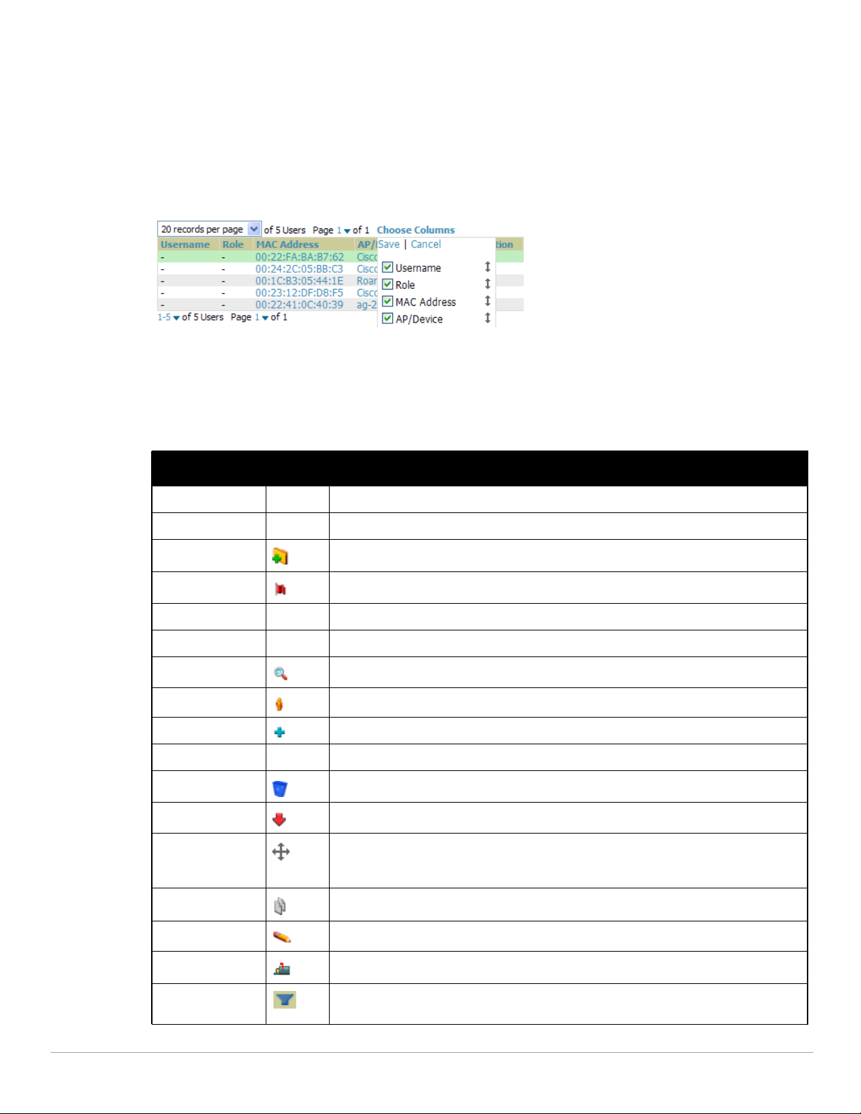
the upper left hand side of a list table) enables you select or enter the number of rows that appear at a time in the
list. The next down arrow displays a dropdown menu that allows you to select the exact page you would like to
view, as shown in Figure 1.
The Choose Columns option, illustrated on Figure 1, allows you to configure the columns that are presented in
the list and the order in which they are presented. To disable a column, clear its checkbox. To reorder the
columns, drag a row to the appropriate new position. When you are satisfied with the enabled columns and their
order, select Save at the top of the columns list.
Figure 1 Common List Settings Choose Columns Illustration
These settings are user specific. To reset them, select Reset List Preferences on Home > User Info.
Buttons and Icons
Standard buttons and icons are used throughout AirWave as follows:
Table 7 Standard Buttons and Icons of the AirWave User Page
Function ImageaDescription
Acknowledge Acknowledges and clears an AirWave alert.
Add Adds the object to both AirWave's database and the onscreen display list.
Add Folder Adds a new folder to hierarchically organize APs.
Alert Indicates an alert.
Apply Applies all “saved” configuration changes to devices on the WLAN.
Audit Reads device configuration, compare to desired, and update status.
Choose Chooses a new Helpdesk incident to be the Current Incident.
Clients Indicates WLAN users. Select this number to see a list of connected clients.
Create Creates a new Helpdesk incident.
Customize Ignores selected settings when calculating the configuration status.
Delete Deletes an object from AirWave's database.
Down Indicates Down devices and radios.
Drag and Drop Dragging and dropping objects with this icon changes the sequence of items in relation to
each other. Refer to “Using RAPIDS and Rogue Classification” on page 167 as one
example of drag-and-drop.
Duplicate Duplicates or makes a copy of the configuration of an AirWave object.
Edit Edits the object properties.
Email Links to email reports.
Filter (Funnel icon) Filters list by values of the selected column. To reset all filters in all columns, click Reset
26 | Installing and Getting Started Dell PowerConnect W-AirWave 7.4 | User Guide
filters link at the bottom of the table.
Page 27
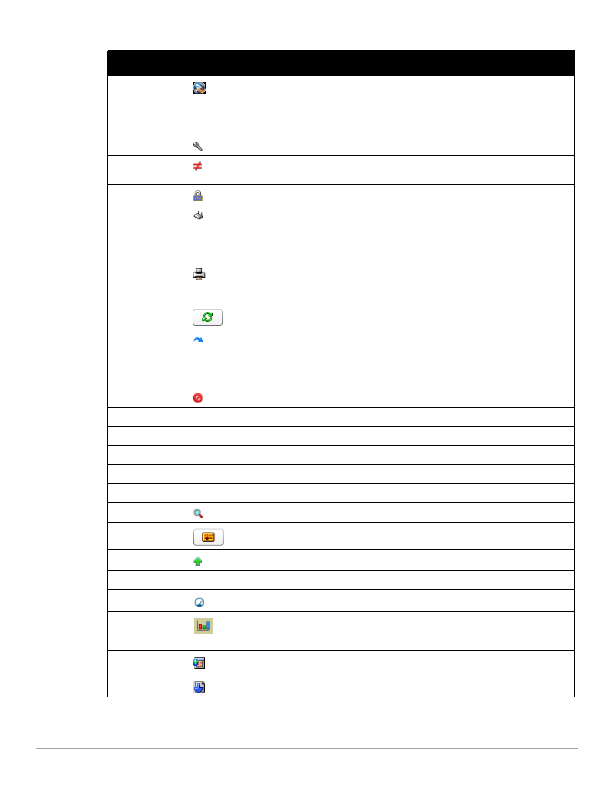
Table 7 Standard Buttons and Icons of the AirWave User Page (Continued)
Function ImageaDescription
Google Earth Views device's location in Google Earth (requires plug-in).
Ignore Ignores specific device(s) - devices selected with check boxes.
Import Updates a Group's desired settings to match current settings.
Manage Manages the object properties.
Mismatched Indicates mismatched device configuration, in which the most recent configuration in
Monitor Indicates an access point is in “monitor only” mode.
New Devices Indicates new access points and devices.
Poll Now Polls device (or controller) immediately, override group polling settings.
Preview Displays a preview of changes applicable to multiple groups.
Print Prints the report.
Reboot Reboots devices or AirWave.
Refresh Refreshes the display of interactive graphs when settings have changed.
Relate Relates an AP, Group or Client to a Helpdesk incident.
Replace Hardware Confers configuration and history of one AP to a replacement device.
Revert Returns all configurable data on the screen to its original status.
Rogue Indicates a rogue AP, and links to RAPIDS.
Run Runs a new user-defined report.
Save Saves the information on the page in the AirWave database.
Save & Apply Saves changes to AirWave’s database and apply all changes to devices.
AirWave and the current configuration on a device are mismatched.
Scan Scans for devices and rogues using selected networks.
Schedule Schedules a window for reports, device changes, or maintenance.
Search Searches AirWave for the specified client, device, rogue, group, folder, tag, or session.
Set Time Range Sets the time range for interactive graphs to the range specified.
Up Indicates devices which are in the Up status.
Update Firmware Applies a new firmware image to an AP/device.
Usage Displays current bandwidth.
View Historical
Graph in New
Window
VisualRF Links to VisualRF - real time visualization.
XML Links to export XHTML versions of reports.
a. Not all AirWave GUI components are itemized in graphic format in this table.
Dell PowerConnect W-AirWave 7.4 | User Guide Installing and Getting Started | 27
Displays all data series for the selected graph over the last two hours, last day, last week,
last month, and last year in one new pop-up window.
Page 28
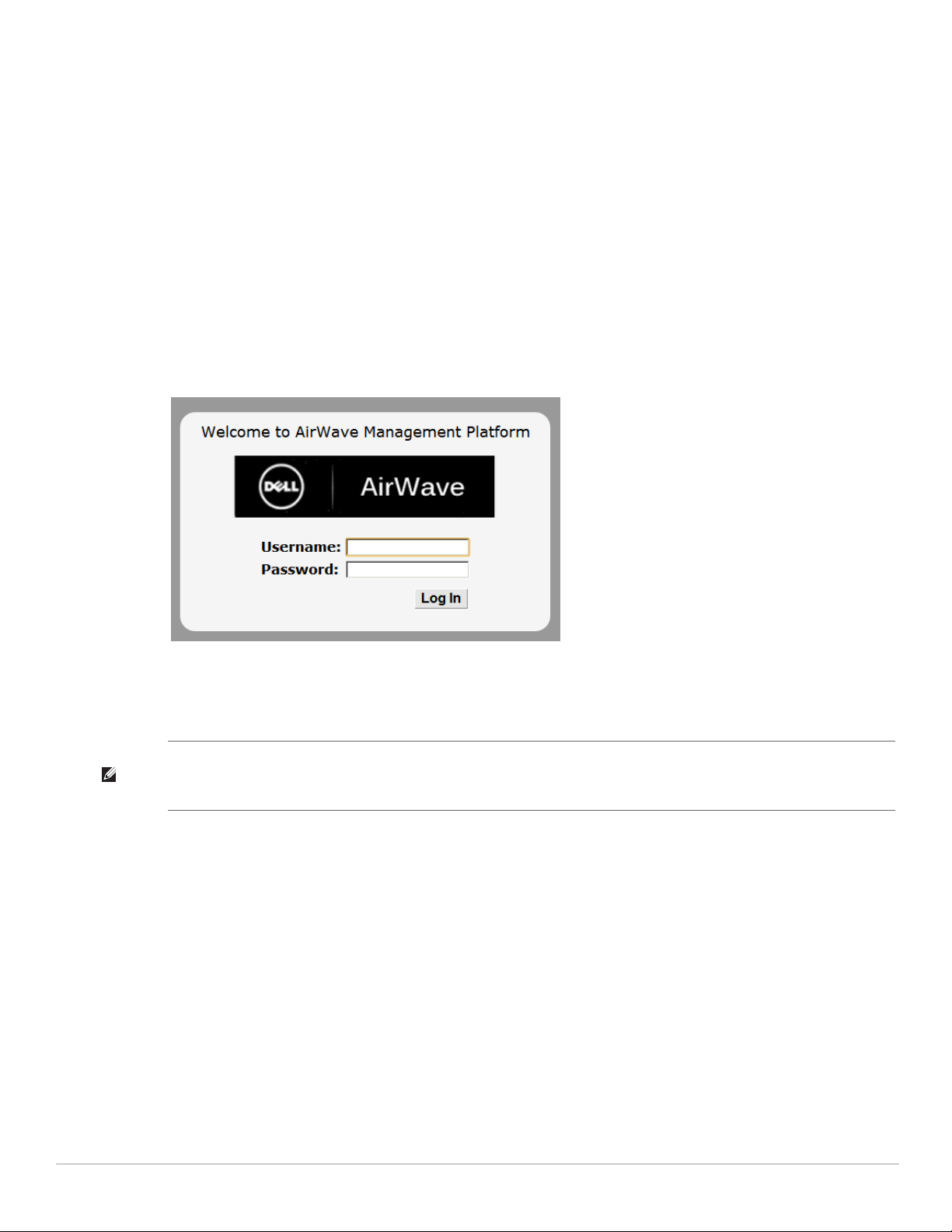
Getting Started with AirWave
This topic describes how to perform an initial launch of the AirWave network management solution on the
session-based authentication scheme introduced in AirWave 7.3.0.
When an AirWave URL is accessed either interactively using a browser or programmatically using an API, a sent
cookie may match a session stored in the database, granting authentication (but not necessarily access, depending
on how the user’s role matches the required role for the URL). If the cookie is not present or the session in the
database has expired, the request is denied.
For browser requests, this results in a login form being displayed. When you submit the login form, the supplied
credentials are checked against the AMP’s user database, an external RADIUS server, or external TACACS+
server per the AMP’s configuration. If the credentials are valid, the user’s browser is sent a session cookie to use in
subsequent requests.
Use your browser to navigate to the static IP address assigned to the internal page of the AirWave, as shown in
Figure 2. Enter the User Name and Password as admin/admin for your initial login, and then select Log In.
Figure 2 AirWave Login Form
If desired, you can set one of the available languages for your login: English and Japanese (Chinese is planned, but
not yet complete as of 7.4.0). AirWave will remember your selected language until you log out and select another.
After successful authentication, your browser launches the AirWave Home > Overview page.
NOTE: AirWave pages are protected via SSL. Some browsers will display a confirmation dialog for your self-signed certificate.
Signing your certificate will prevent this dialog from displaying. Changing the default login and password on the AMP Setup >
Users page is recommended. Refer to the procedure “Creating AirWave User Roles” on page 46 for additional information.
28 | Installing and Getting Started Dell PowerConnect W-AirWave 7.4 | User Guide
Page 29

Chapter 3
Configuring AMP
This chapter contains the following procedures to deploy initial AMP configuration:
“Formatting the Top Header” on page29
“Customizing Columns in Lists” on page30
“Resetting Pagination Records” on page31
“Using the Pagination Widget” on page31
“Using Export CSV for Lists and Reports” on page31
“Defining Graph Display Preferences” on page32
“Customizing the Dashboard” on page32
“Setting Severe Alert Warning Behavior” on page34
“Defining General AirWave Server Settings” on page35
“Defining AirWave Network Settings” on page43
“Creating AirWave Users” on page44
“Creating AirWave User Roles” on page46
“Configuring Login Message, TACACS+ and RADIUS Authentication” on page48
“Enabling AirWave to Manage Your Devices” on page52
“Setting Up Device Types” on page58
“Configuring Cisco WLSE and WLSE Rogue Scanning” on page58
“Configuring ACS Servers” on page63
“Integrating AirWave with an Existing Network Management Solution (NMS)” on page64
“Auditing PCI Compliance on the Network” on page65
“Deploying WMS Offload” on page67
NOTE: Additional configurations of multiple types are available after basic configuration is complete.
Before You Begin
Remember to complete the required configurations in this chapter before proceeding. AirWave support remains
available to you for any phase of AirWave installation.
Formatting the Top Header
The Dell PowerConnect W-AirWave 7.4 interface centers around a horizontal row of tabs with nested subtabs.
A row of statistics hyperlinks called Top Header Stats above the tabs represents commonly used subtabs. These
hyperlinks provide the ability to view certain key statistics by mousing over, such as number and type of Down
devices, and serve as shortcuts to frequently viewed subtabs. Figure 3 illustrates the navigation bar. For more
details on hyperlinks, tabs and subtabs, see “AirWave Navigation Basics” on page22.
Figure 3 Navigation Bar Displaying Down Device Statistics
Dell PowerConnect W-AirWave 7.4 | User Guide Configuring AMP | 29
Page 30
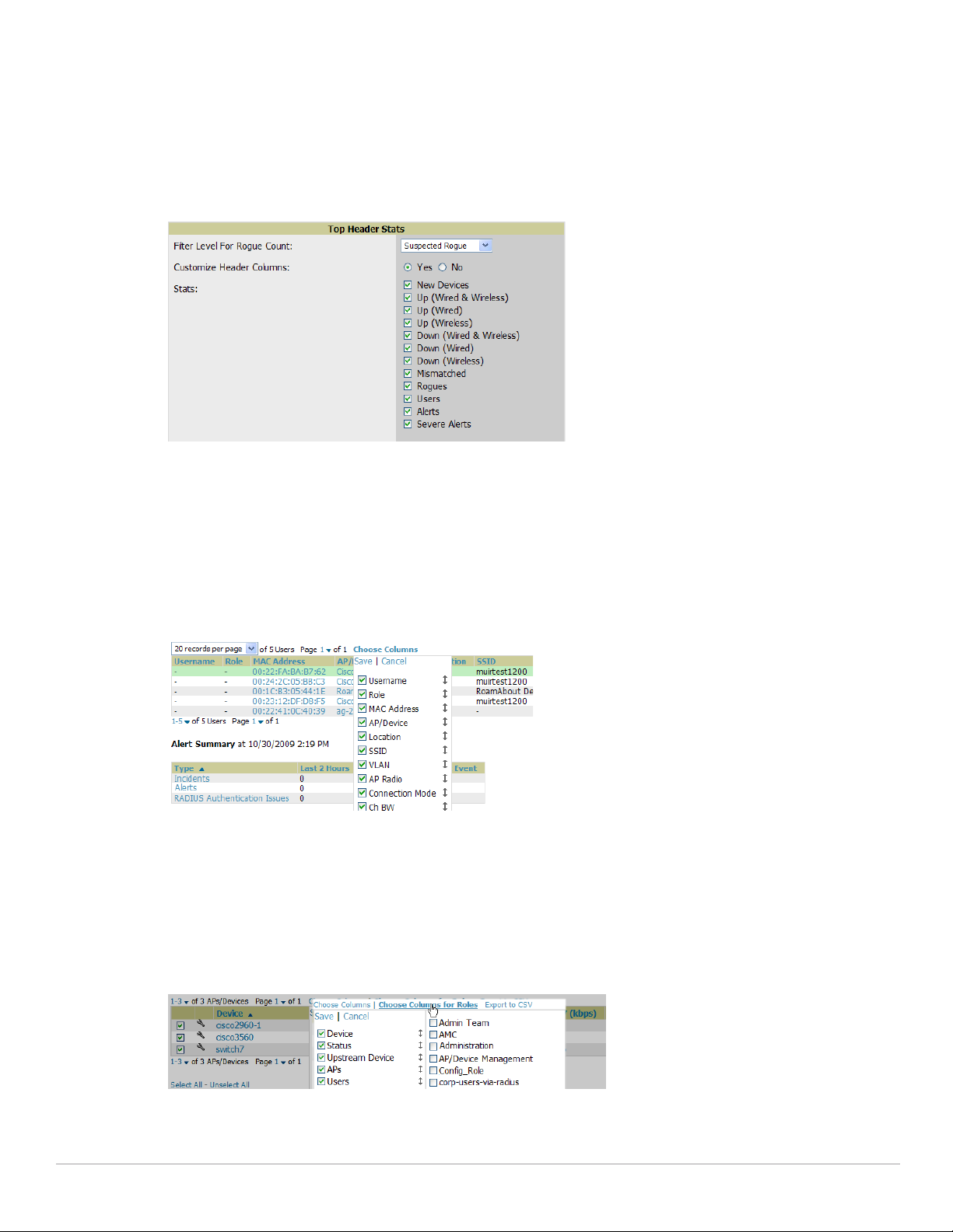
You can control which Top Header Stats links appear from the AMP Setup > General page, as described in
“Defining General AirWave Server Settings” on page35. Top Header Stats can also be customized for individual
user on the Home > User Info page. There you can select the statistics to display for certain device types, and
override the AMP Setup page.
All possible display options for users are shown in Figure 4, and these fields are described in detail in “Configuring
Your Own User Information with the Home > User Info Page” on page214.
Figure 4 Home > User Info Top Header Stats Display Options
You can also set the severity level of critical alerts displayed for a user role. For details including a description of
what constitutes a severe alert, see “Setting Severe Alert Warning Behavior” on page34.
Customizing Columns in Lists
Customize the columns for any list table selecting Choose Columns as shown in Figure 5. Use the up/down
arrows to change the order in which the column heads appear.
Figure 5 Choose Columns Dropdown List
For more information on the universal list elements, see “Common List Settings” on page25.
You can also control which column heads appear for each user role by selecting Yes in the Customize Header
Columns field in Home > User Info, as also appears in Figure 4. This exposes the Choose Columns for Roles
dropdown menu in all tables shown in Figure 6.
The first column shows the user roles that were customized, if any. The second column allows you to establish left
to right columns and order them using the arrows.
Figure 6 Table With Choose Columns for Roles Menu Selected
30 | Configuring AMP Dell PowerConnect W-AirWave 7.4 | User Guide
Page 31

Resetting Pagination Records
To control the number of records in any individual list, select the link with Records Per Page mouseover text at
the top left of the table, as shown in Figure 7. AirWave remembers each list table’s pagination preferences.
Figure 7 Records Per Page Drop Down Menu
To reset all Records Per Page preferences, select Reset in the Display Preferences section of the Home > User
Info page, as shown in Figure 8.
Figure 8 Home > User Info Display Preferences section
Using the Pagination Widget
The pagination widget is located at the top and bottom of every list table, as shown in Figure 9.
Figure 9 Pagination Widget
Use the down arrow next to Page 1 to see all the page numbers for that table in a dropdown menu. From here,
you can jump to any portion of the table. Select the > symbol to jump to the next page, and >| to jump to the
last page.
Using Export CSV for Lists and Reports
Some tables have a Export CSV setting you can use export the data as a spreadsheet. See Figure 10 for an
example of a list with the Export CSV option selected.
Figure 10 List with CSV Export Selected
AirWave also enables CSV exporting of all report types. For more information, see “Exporting Reports to XML or
CSV” on page255.
Dell PowerConnect W-AirWave 7.4 | User Guide Configuring AMP | 31
Page 32

Defining Graph Display Preferences
Many of the graphs in AirWave are Flash-based which allows you adjust the graph settings attributes, as shown in
Figure 11.
Figure 11 Interactive Graphs on the Home > Overview Page
This Flash-enabled GUI allows for custom settings and adjustments, as follows:
Drag the slider at the bottom of the screen to move the scope of the graph between one year ago and the
current time.
Drag the slider between graphs to change the relative sizes of each.
Deselect checkboxes to change the data displayed on each graph. The button with green arrows refreshes data
on the graph.
The Show All link displays all of the available checkboxes supporting the Flash graphs.
Once a change to the slider bars or to the display boxes has been made, the same change can be applied to all
other Flash graphs with an apply button (appears on mouse-over only).
For non-Flash graphs, select the graph to open a popup window that shows historical data.
A non-Flash version of the AirWave user page is available if desired; instead of Flash it uses the RRD graphs that
were used in earlier versions of AirWave. Contact AirWave support for more information on activating this
feature in the AirWave database.
Customizing the Dashboard
You can rearrange or remove widgets appearing on the Home > Overview dashboard by selecting the Customize
link to the right of this window, as shown in Figure 12.
Figure 12 Customize Button on the Home > Overview Page
The Customize workspace that appears is shown in Figure 13.
32 | Configuring AMP Dell PowerConnect W-AirWave 7.4 | User Guide
Page 33

Figure 13 Customize Overview Page
The Available Widgets section on the left with no gridlines holds all possible (available) graphical elements
(widgets). Select any blue widget tile with a verbal description enclosed, and it immediately turns into a graphical
element with a description.
Drag the widgets you want to appear on the Overview dashboard across to the gridlines and arrange them in the
right section, within the gridlines. A widget snaps back to the nearest available gridline if you drop it across two or
more lines, and turns red if you attempt to place it over gridlines already occupied by widgets.
Green widgets are properly placed and set to appear when you select Save. Widgets that remain in the left section
will not appear (although they can be reinstated by selecting Restore Defaults).
Dell PowerConnect W-AirWave 7.4 | User Guide Configuring AMP | 33
Page 34

Customized Search
You can customize the Full search results to display only desired categories of matches on the Home > User Info
page. Go to the Search Preferences section and select Yes in the Customize Search field, then select or unselect
categories of results and save your changes. Customized search is turned off by default, and all boxes are selected.
Figure 14 Home > User Info Customized Search Preferences
Setting Severe Alert Warning Behavior
You can control the alert levels you can see on the Alerts top header stats link from the Home > User Info page.
When a trigger is assigned a severity of Critical, it generates a severe alert. When a severe alert exists, a new
component named Severe Alerts appears at the right of the Status field in bold red font.
Only users who are enabled for viewing critical alerts on the Home > User Info page can see severe alerts. The
Severe Alert Threshold dropdown menu, located in the Top Header Stats section of the Home > User Info page
is shown in Figure 15.
Figure 15 Home > User Info > Severe Alert Threshold Dropdown Menu
34 | Configuring AMP Dell PowerConnect W-AirWave 7.4 | User Guide
Page 35

Defining General AirWave Server Settings
This section describes all pages accessed from the AMP Setup tab and describes two pages in the Device Setup
tab—the Communication and Upload Files pages. Once required and optional configurations in this chapter are
complete, continue to later chapters in this document to create and deploy device groups and device
configuration and discovery on the network.
The first step in configuring AirWave is to specify the general settings for the AirWave server. Figure 16
illustrates the AMP Setup > General page:
Figure 16 AMP Setup > General Page Illustration (Partial View)
Dell PowerConnect W-AirWave 7.4 | User Guide Configuring AMP | 35
Page 36

Perform the following steps to configure AirWave server settings globally across the product (for all users).
1. Browse to the AMP Setup > General page, locate the General section, and enter the information described in
Table 8:
Table 8 AMP Setup > General > General Section Fields and Default Values
Setting Default Description
System Name Defines your name for the AirWave server, with a maximum limit of 20alphanumeric
Automatically
monitor/manage new
devices
Default Group Access
Device Configuration
Audit Interval
No Launches a drop-down menu that specifies the behavior AirWave should follow
Points
Daily If enabled, this setting defines the interval of queries which compares actual
characters.
when it discovers a new device. Devices are placed in the default group which is
defined in the next field. Choose one of these options:
Monitor Only: AirWave compares the current configuration with the policy, and
displays any discrepancies on the APs/Devices > Audit page, but does not
change the configuration of the device.
Manage Read/Write: AirWave compares the device's current configuration
settings with the Group configuration settings and automatically updates the
device's configuration to match the Group policy. Automatically placing
devices in Managed Read/Write mode will overwrite the configuration with the
desired configuration in AirWave, and should only be used when you are
certain AirWave has the correct configuration. Thiscan be risky, and generally,
devices should be placed in Monitor Only mode as the default.
Thin APs Only: Only thin APs will be automatically authorized in Monitor Only
mode. This setting is ideal for mixed environments of thin and autonomous APs,
or for very large subnets in which you don’t want to auto-monitor all switches.
Sets the device group that this AirWave server uses as the default for device-level
configuration. Select a device group from the drop-down menu. A group must first
be defined on the Groups > List page to appear in this drop-down menu. For
additional information, refer to Chapter 4, “Configuring and Using Device Groups in
AirWave” on page 69.
device settings to the Group configuration policies stored in the AirWave database.
If the settings do not match, the AP is flagged as mismatched and AirWave sends
an alert via email, log, or SNMP.
NOTE: Enabling this feature with a frequency of Daily or more frequently is
recommended to ensure that your AP configurations comply with your established
policies.
Automatically repair
misconfigured
devices
Send debugging
messages
Nightly Maintenance
Time (00:00 - 23:59)
Check for software
updates
Disabled If enabled, this setting automatically reconfigures the settings on the device when
the device is in Manage mode and AirWave detects a variance between actual
device settings and the Group configuration policy in the AirWave database.
Enabled If enabled, AirWave automatically emails any system errors to AirWave Support to
assist in debugging.
04:15 Specifies the local time of day AirWave should perform daily maintenance. During
maintenance, AirWave cleans the database, performs backups, and completes a
few other housekeeping tasks. Such processes should not be performed during
peak hours of demand.
Yes Enables AirWave to check automatically for multiple update types. Check daily for
AirWave updates, to include enhancements, device template files, important
security updates, and other important news. This setting requires a direct internet
connection via AirWave.
2. On the AMP Setup > General page, locate the Automatic Authorization section. These settings allow you to
control the conditions by which devices are automatically authorized into AP groups and folders. AMP
36 | Configuring AMP Dell PowerConnect W-AirWave 7.4 | User Guide
Page 37
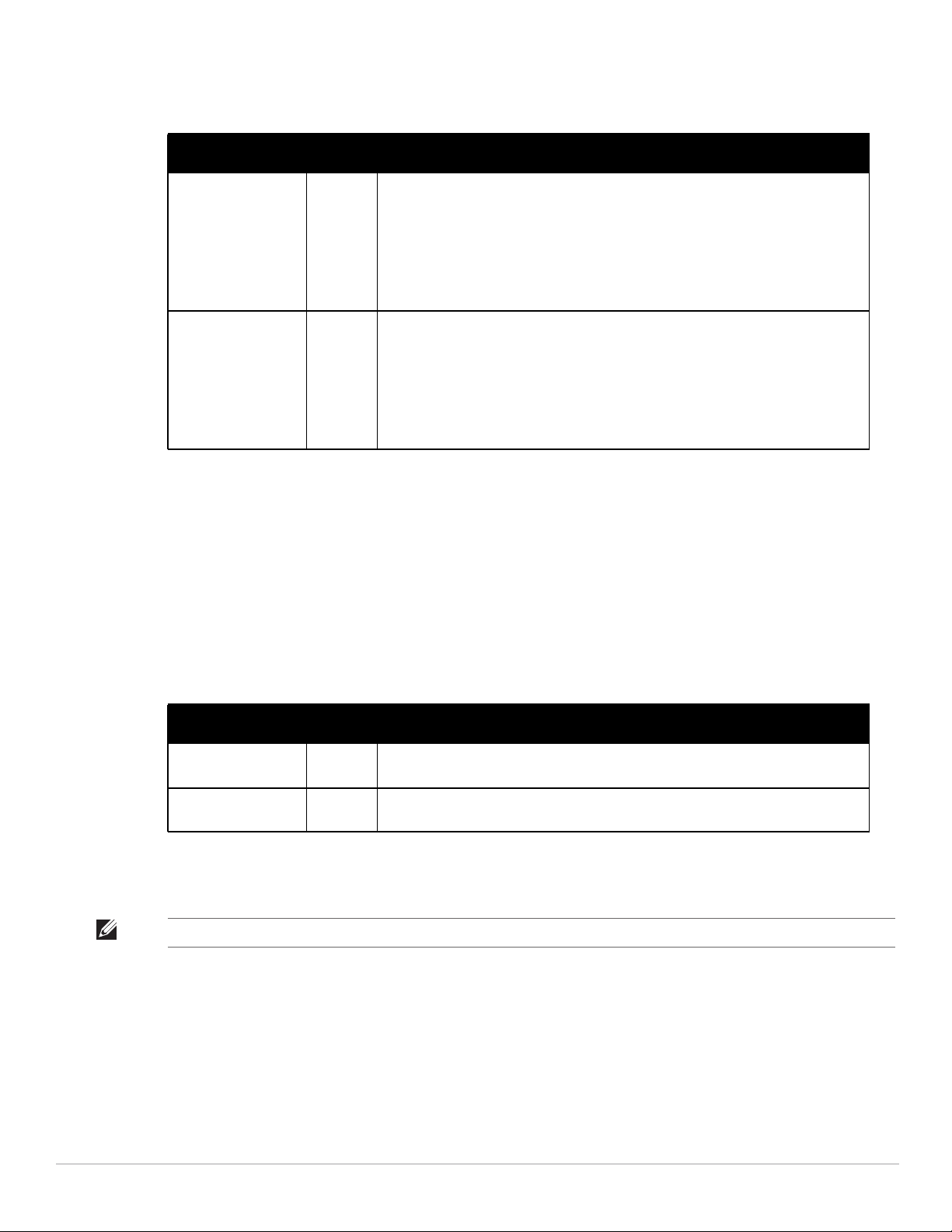
validates the Folder and Group to ensure that both settings have been set to valid dropdown options. Table 9
describes the settings and default values in this section.
Table 9 AMP Setup > General > Automatic Authorization Fields and Default Values
Setting Default Description
Add New Controllers
and Autonomous
Devices Location
Add New Thin APs
Location
New
Device
List
New
Device
List
Globally add new controllers and autonomous devices to:
The New Devices list (located in APs/Devices > New).
The same folder and group as the discovering device.
The same group and folder of their closest IP neighbor on the same subnet.
Choose a group and folder. If you select this option, enter the folder/group in the
Auto Authorization Group and Auto Authorization Folder fields that display.
NOTE: This setting can be overridden in Groups > Basic.
Globally add new thin APs to:
The New Devices list.
The same folder and group as the discovering device.
The same group and folder of their closest IP neighbor on the same subnet.
Choose a group and folder. If you select this option, enter the folder/group in the
Auto Authorization Group and Auto Authorization Folder fields that display.
NOTE: This setting can be overridden in Groups > Basic.
3. On the AMP Setup > General page, locate the Top Header section to select the Top Header Stats to be
displayed at the top of the interface. For more detailed information about each option, refer to Table 5 on
page 22.
4. On the AMP Setup > General page, locate the Search Preferences section. Select the search categories to
include in a “Full” search of AMP such APs/devices, clients (connected and/or historical), VPN sessions
(connected and/or historical), rogues, rogue clients, tags, folders, and groups. All are selected by default. Peruser search preferences can be set in the Home > User Info page; refer to “Customized Search” on page34.
5. On the AMP Setup > General page, locate the Home Overview Preferences section. Table 11 describes the
settings and default values in this section.
Table 10 AMP Setup > General > Home Overview Preferences Fields and Default Values
Setting Default Description
Configure Channel
Busy Threshold
Channel Busy
Threshold (%)
6. On the AMP Setup > General page, locate the Display section and select the Group tabs and options to
appear by default in new device groups.
NOTE: Changes to this section apply across all of AirWave. These changes affect all users and all new device groups.
Yes Whether you want to configure the threshold at which a channel is considered to be
busy at the Top Folders By Radio Channel Usage Overview widget.
10 The threshold percent at which the radio channel is considered busier than normal.
Dell PowerConnect W-AirWave 7.4 | User Guide Configuring AMP | 37
Page 38

Table 11 describes the settings and default values in this section.
Table 11 AMP Setup > General > Display Fields and Default Values
Setting Default Description
Use fully qualified
domain names
Show vendor-specific
device settings for
Look up wireless user
hostnames
DNS Hostname
Lifetime
Device
Troubleshooting Hint
No Sets AirWave to use fully qualified domain names for APs instead of the AP name. For
example, "testap.yourdomain.com" would be used instead of "testap."
This option is supported only for Cisco IOS, Dell PowerConnect W, Aruba Networks,
and Alcatel-Lucent devices.
All Devices Displays a drop-down menu that determines which Group tabs and options are
viewable by default in new groups, and selects the device types that use fully qualified
domain names. This field has three options, as follows:
All devices—When selected, AirWave displays all Group tabs and setting options.
Only devices on this AMP—When selected, AirWave hides all options and tabs
that do not apply to the APs and devices currently on AirWave.
Selected device type—When selected, a new field appears listing many device
types. This option allows you to specify the device types for which AirWave
displays group settings. You can override this setting.
Yes Enables AirWave to look up the DNS for new user hostnames. This setting can be
turned off to troubleshoot performance issues.
24 hours Defines the length of time, in hours, for which a DNS server hostname remains valid on
AirWave, after which AirWave refreshes DNS lookup:
1 hour
2 hours
4 hours
12 hours
24 hours
N/A The message included in this field is displayed along with the Down if a device’s
upstream device is up. This applies to all APs and controllers but not to routers and
switches.
7. Locate the Device Configuration section and adjust the settings. Table 12 describes the settings and default
values of this section.
Table 12 AMP Setup > General > Device Configuration Section Fields and Default Values
Setting Default Description
Guest User
Configuration
Allow WMS Offload
configuration in
monitor-only mode
Allow disconnecting
users while in monitoronly mode
Allow non-UTF8
characters
Disabled Enables or prevents guest users to/from pushing configurations to devices. Options are
Disabled (default), Enabled for Devices in Manage (Read/Write), Enabled for all
Devices.
No When Yes is selected, you can enable the ArubaOS WMS offload feature on the
Groups > Basic page for WLAN switches in Monitor Only mode. Enabling WMS offload
does not cause a controller to reboot. This option is supported only for Dell and Dell
PowerConnect W-Series devices.
No Sets whether you can deauthenticate a user for a device in monitor-only mode. If set to
No, the Deauthenticate Client button for in a Clients > Client Detail page is enabled only
for Managed devices.
No Whether AMP can use character sets other than UTF-8 for configuration settings.
38 | Configuring AMP Dell PowerConnect W-AirWave 7.4 | User Guide
Page 39

Table 12 AMP Setup > General > Device Configuration Section Fields and Default Values (Continued)
Setting Default Description
Use Global
PowerConnect W
Configuration
Yes Enables Dell configuration profile settings to be globally configured and then assigned
to device groups. If disabled, settings can be defined entirely within Groups > Dell
PowerConnect W Config instead of globally.
NOTE: Changing this setting may require importing configuration on your devices.
When an existing Dell PowerConnect W-Series configuration setup is to be converted
from global to group, follow these steps:
1. Set all the devices to Monitor Only mode before setting the flag.
2. Each device Group will need to have an import performed from the Audit page of a
controller in the AMP group.
3. All of the thin APs need to have their settings imported after the device group
settings have finished importing.
4. If the devices were set to Monitor Only mode, set them back to Managed mode.
5. Locate the AMP Features section and adjust settings to enable or disable VisualRF and RAPIDS. Table 13
describes these settings and default values.
Table 13 AMP Setup > General > AMP Features Fields and Default Values
Setting Default Description
Display VisualRF No Enable or disable the VisualRF navigation tab.
Display RAPIDS No Enable or disable the RAPIDS navigation tab.
Hide setup pages from
non-admin users
Yes Restrict access to following pages to users with the AMP Administration role only:
VisualRF > Setup
AMP Setup > NMS
RAPIDS > Score Override
RAPIDS > Rules
RAPIDS > Setup
System > Triggers
Allow role based report
visibility
Yes Enable or disable role-based reporting in AMP. When disabled, reports can only be
generated with by-subject visibility.
6. Locate the External Logging section and adjust settings to send audit and system events to an external syslog
server. Table 14 describes these settings and default values. You can send a test message using the Send Test
Message button once any of the logging options are enabled.
Table 14 AMP Setup > General > External Logging Section Fields and Default Values
Setting Default Description
Include event log
messages
Syslog Server N/A Enter the IP address of the syslog server.
Syslog Port 514 Enter the port of the syslog server.
Event log facility local1 Select the facility for the event log from the drop-down menu.
Include audit log
messages
Audit log facility local1 Select the facility for the audit log from the drop-down menu.
No Select Yes to send event log messages to an external syslog server.
No Select Yes to send audit log messages to an external syslog server.
Dell PowerConnect W-AirWave 7.4 | User Guide Configuring AMP | 39
Page 40

7. Locate the Historical Data Retention section and specify the number of days you wish to keep client session
records and rogue discovery events. Table 15 describes the settings and default values of this section. Many
settings can be set to have no expiration date.
Table 15 AMP Setup > General > Historical Data Retention Fields and Default Values
Setting Default Description
Inactive Client and
VPN User Data
(0-1500 days, zero
disables)
Client Association and
VPN Session History
(2-550 days)
Tag History
(2-550 days)
Rogue AP Discovery
Events
(2-550 days)
Reports
(2-550 days)
Automatically
Acknowledge Alerts
(0-550 days, zero
disables)
Acknowledged Alerts
(2-550 days)
Radius/ARM/IDS
Events
(0-550 days, zero
disables)
60 Defines the number of days AirWave stores basic information about inactive clients and
VPN users. A shorter setting of 60 days is recommended for customers with high user
turnover such as hotels. The longer you store inactive user data, the more hard disk space
you require.
14 Defines the number of days AirWave stores client and VPN session records. The longer
you store client session records, the more hard disk space you require.
14 Sets the number of days AirWave retains location history for Wi-Fi tags.
14 Defines the number of days AirWave stores Rogue Discovery Events. The longer you store
discovery event records, the more hard disk space you require.
60 Defines the number of days AirWave stores Reports. Large numbers of reports, over 1000,
can cause the Reports > Generated page to be slow to respond.
14 Defines automatically acknowledged alerts as the number of days AirWave retains alerts
that have been automatically acknowledged. Setting this value to 0 disables this function,
and alerts will never expire or be deleted from the database.
60 Defines the number of days AirWave retains information about acknowledged alerts.
Large numbers of Alerts, over 2000, can cause the System > Alerts page to be slow to
respond.
14 Defines the number of days AirWave retains information about RADIUS, ARM, and IDS
events. Setting this value to 0 disables this function, and the information will never expire
or be deleted from the database.
Archive device configs
even if they only have
rogue classifications
(1-100)
Guest Users
(0-550 days, zero
disables)
Inactive SSIDs
(0-550 days, zero
disables)
Inactive Interfaces (0550 days, zero
disables)
Interface Status
History
(0-550 days, zero
disables)
Interfering Devices (0550 days, zero
disables)
Device Events (Syslog,
Traps)
No Sets whether to archive device configurations even if the device only has rogue
classifications.
30 Sets the number of days that AirWave is to support any guest user. A value of 0 disables
this function, and guest users will never expire or be deleted from the AirWave database.
425 Sets the number of days AirWave retains historical information after AirWave last saw a
client on a specific SSID. Setting this value to 0 disables this function, and inactive SSIDs
will never expire or be deleted from the database.
425 Sets the number of days AirWave retains inactive interface information after the interface
has been removed or deleted from the device. Setting this value to 0 disables this function,
and inactive interface information will never expire or be deleted from the database.
425 Sets the number of days AirWave retains historical information on interface status.
Setting this value to 0 disables this function.
14 Sets the number of days AirWave retains historical information on interfering devices.
Setting this value to 0 disables this function.
2 Sets the number of days AirWave retains historical information on device events such as
syslog entries and SNMP traps. Setting this value to 0 disables this function. Refer to
“Viewing Device Events in System > Syslog & Traps” on page 185.
40 | Configuring AMP Dell PowerConnect W-AirWave 7.4 | User Guide
Page 41

Table 15 AMP Setup > General > Historical Data Retention Fields and Default Values (Continued)
Setting Default Description
Device Uptime (0-120
months, zero disables)
60 Sets the number of months AirWave retains historical information on device uptime.
Setting this value to 0 disables this function.
8. Locate the Firmware Upgrade Defaults section and adjust settings as required. This section allows you to
configure the default firmware upgrade behavior for AirWave. Table 16 describes the settings and default
values of this section.
Table 16 AMP Setup > General > Firmware Upgrade Defaults Fields and Default Values
Setting Default Description
Allow firmware
upgrades in monitoronly mode
Simultaneous Jobs (1-
20)
Simultaneous Devices
Per Job
(1-1000)
Failures before
stopping (0-20)
No If Yes is selected, AirWave upgrades the firmware for APs in Monitor Only mode. When
AirWave upgrades the firmware in this mode, the desired configuration are not be pushed
to AirWave. Only the firmware is applied. The firmware upgrade may result in
configuration changes. AirWave does not correct those changes when the AP is in
Monitor Only mode.
20 Defines the number of jobs AirWave runs at the same time. A job can include multiple
APs.
20 Defines the number of devices that can be in the process of upgrading at the same time.
AirWave only runs one TFTP transfer at a time. As soon as the transfer to a device has
completed, the next transfer begins, even if the first device is still in the process of
rebooting or verifying configuration.
1 Sets the default number of upgrade failures before AirWave pauses the upgrade process.
User intervention is required to resume the upgrade process. Setting this value to 0
disables this function.
9. Locate the Additional AMP Services section, and adjust settings as required. Table 17 describes the settings
and default values of this section.
Table 17 AMP Setup > General > Additional AMP Services Fields and Default Values
Setting Default Description
Enable FTP Server No Enables or disables the FTP server on AMP. The FTP server is only used to manage Cisco
Enable RTLS Collector No Enables or disables the RTLS Collector, which is used to allow Dell PowerConnect W-
Use embedded mail
server
Yes Enables or disables the embedded mail server that is included with AirWave.This field
Aironet 4800 APs. Disabling the FTP server is recommended if you do not have any Cisco
Aironet 4800 APs in the network.
Series controllers to send signed and encrypted RTLS (real time locating system) packets
to VisualRF--in other words, AirWave becomes the acting RTLS server. The RTLS server IP
address must be configured on each controller. This function is used for VisualRF to
improve location accuracy and to locate chirping asset tags. This function is supported
only for Dell PowerConnect W-Series, Alcatel-Lucent and Aruba Networks devices.
With selection of Yes, the following additional fields appear, which you should populate to
match the settings configured on the controller:
RTLS Port—Specify the port for the AirWave RTLS server.
RTLS Username—Enter the user name used by the controller to decode RTLS
messages.
RTLS Password—Enter the RTLS server password that matches the controllers’ value.
supports a Send Test Email button for testing server functionality. This button prompts you
with a To and From field in which you must enter valid email addresses, and a button to
send a test email.
Process user roaming
traps from Cisco WLC
Dell PowerConnect W-AirWave 7.4 | User Guide Configuring AMP | 41
Yes Whether AMP should parse client association and authentication traps from Cisco WLC
controllers to give real time information on users connected to the wireless network.
Page 42

Table 17 AMP Setup > General > Additional AMP Services Fields and Default Values (Continued)
Setting Default Description
Enable AMON data
collection
Yes Allows AMP to collect enhanced data from Dell PowerConnect W-Series devices on
certain firmware versions; see the Dell PowerConnect W-AirWave 7.4 Best Practices
Guide in Home > Documentation for more details.
10. Locate the Performance section. Performance tuning is unlikely to be necessary for many AirWave
implementations, and likely provides the most improvements for customers with extremely large Pro or
Enterprise installations. Contact Dell support
at support.dell.com if you think you might need to change any of
these settings. Table 18 describes the settings and default values of this section.
Table 18 AMP Setup > General > Performance Fields and Default Values
Setting Default Description
Monitoring
Processes
Maximum number of
configuration
processes
Maximum number of
audit processes
Based on the
number of
cores for your
server
5 Increases the number of processes that are pushing configurations to your devices,
3 Increases the number of processes that audit configurations for your devices, as an
Optional setting configures the throughput of monitoring data. Increasing this setting
allows AirWave to process more data per second, but it can take resources away
from other AirWave processes. Contact Dell support at support.dell.com if you think
you might need to increase this setting for your network.
as an option. The optimal setting for your network depends on the resources
available, especially RAM. Contact Dell support at support.dell.com if you think you
might need to increase this setting for your network.
option. The optimal setting for your network depends on the resources available,
especially RAM. Contact Dell support at support.dell.com if you are considering
increasing this setting for your network.
Verbose Logging of
SNMP Configuration
SNMP Rate Limiting
for Monitored
Devices
RAPIDS Processing
Priority
No Enables or disables logging detailed records of SNMP configuration information.
No When enabled, AirWave fetches SNMP data more slowly, potentially reducing
device CPU load. Enabling this global setting is recommended when monitoring Dell
PowerConnect W-Series controllers only if your network contains a majority of
legacy controllers (800, 2400, 5000, controllers that use Supervisor Module II). If your
network mainly uses newer processors (3000 series, 600 series, the M3 module in the
6000 series), disabling this setting is strongly recommended.
Low Defines the processing and system resource priority for RAPIDS in relation to
AirWave as a whole.
When AirWave is processing data at or near its maximum capacity, reducing the
priority of RAPIDS can ensure that processing of other data (such as client
connections and bandwidth usage) is not adversely impacted.
The default priority is Low. You can also tune your system performance by changing
group poll periods.
11. Select Save when the General Server settings are complete and whenever making subsequent changes.
What Next?
Go to additional tabs in the AMP Setup section to continue additional setup configurations.
Complete the required configurations in this chapter before proceeding. AirWave support remains available to
you for any phase of AirWave installation.
42 | Configuring AMP Dell PowerConnect W-AirWave 7.4 | User Guide
Page 43

Defining AirWave Network Settings
The next step in configuring AirWave is to confirm the AirWave network settings. Define these settings by
navigating to the AMP Setup > Network page. Figure 17 illustrates the contents of this page.
Figure 17 AMP Setup > Network Page Illustration
Perform the following steps to define the AirWave network settings:
1. Locate the Primary and Secondary Network Interface sections. The information in these sections should
match what you defined during initial network configuration and should not require changes. Table 19
describes the settings and default values.
Table 19 Primary and Secondary Network Interface Fields and Default Values
Setting
IP Address None Sets the IP address of the AirWave network interface.
Hostname None Sets the DNS name assigned to the AirWave server.
Subnet Mask None Sets the subnet mask for the primary network interface.
Gateway None Sets the default gateway for the network interface.
Primary DNS IP None Sets the primary DNS IP address for the network interface.
Secondary DNS IP None Sets the secondary DNS IP address for the network interface.
Secondary Network
Interface
2. On the
AMP Setup > Network page, locate the Network Time Protocol (NTP) section. The Network Time
Default Description
NOTE: This address must be a static IP address.
No Select Yes to enable a secondary network interface. You must also define the IP
address and subnet mask.
Protocol is used to synchronize the time between AirWave and your network reference NTP server. NTP
servers synchronize with external reference time sources, such as satellites, radios, or modems.
NOTE: Specifying NTP servers is optional. NTP servers synchronize the time on the AirWave server, not on individual access
points.
To disable NTP services, clear both the Primary and Secondary NTP server fields. Any problem related to
communication between AirWave and the NTP servers creates an entry in the event log. Table 20 describes
the settings and default values in more detail. For more information on ensuring that AMP servers have the
correct time, please see http://support.ntp.org/bin/view/Servers/NTPPoolServers.
Table 20 AMP Setup > Network > Secondary Network Fields and Default Values
Setting Default Description
Primary ntp1.yourdomain.com Sets the IP address or DNS name for the primary NTP server.
Dell PowerConnect W-AirWave 7.4 | User Guide Configuring AMP | 43
Page 44

Table 20 AMP Setup > Network > Secondary Network Fields and Default Values (Continued)
Setting Default Description
Secondary ntp2.yourdomain.com Sets the IP address or DNS name for the secondary NTP server.
3. On the AMP Setup > Network page, locate the Static Routes area. This section displays network, subnet
mask, and gateway settings that you have defined elsewhere from a command-line interface.
NOTE: This section does not enable you to configure new routes or remove existing routes.
4. Select Save when you have completed all changes on the AMP Setup > Network page, or select Revert to
return to the last settings. Save restarts any affected services and may temporarily disrupt your network
connection.
What Next?
Go to additional tabs in the AMP Setup section to continue additional setup configurations.
Complete the required configurations in this chapter before proceeding. AirWave support remains available to
you for any phase of AirWave configuration.
Creating AirWave Users
AirWave installs with only one AMP user—the admin, who is authorized to:
define additional users with varying levels of privilege, be it manage read/write or monitoring.
limit the viewable devices as well as the level of access a user has to the devices.
Each general user that you add needs a Username, a Password, and a Role. Use unique and meaningful user
names as they are recorded in the log files when you or other users make changes in AirWave.
NOTE: Username and password are not required if you configure AirWave to use RADIUS or TACACS authentication. You do not
need to add individual users to the AirWave server if you use RADIUS or TACACS authentication.
The user role defines the user type, access level, and the top folder for that user. User roles are defined on the
AMP Setup > Roles page. Refer to the next procedure in this chapter for additional information, “Creating
AirWave User Roles” on page46.
The admin user can provide optional additional information about the user including the user's real name, email
address, phone number, and so forth.
Perform the following steps to display, add, edit, or delete AirWave users of any privilege level. You must be an
admin user to complete these steps.
1. Go to the AMP Setup > Users page. This page displays all users currently configured in AirWave. Figure 18
illustrates the contents and layout of this page.
Figure 18 AMP Setup > Users Page Illustration
44 | Configuring AMP Dell PowerConnect W-AirWave 7.4 | User Guide
Page 45

2. Select Add to create a new user, select the pencil icon to edit an existing user, or select a user and select
Delete to remove that user from AirWave. When you select Add or the edit icon, the Add User page appears,
illustrated in Figure 19.
Figure 19 AMP Setup > Users > Add/Edit User Page Illustration
3. Enter or edit the settings on this page. Table 21 describes these settings in additional detail.
Table 21 AMP Setup > Users > Add/Edit User Fields and Default Values
Setting Default Description
Username None Sets the username as an alphanumeric string. The Username is used when logging in to AirWave
Role None Specifies the User Role that defines the Top viewable folder, type and access level of the user
Password None Sets the password for the user being created or edited. Enter an alphanumeric string without
Name None Allows you to define an optional and alphanumeric text field that takes note of the user's actual
Email Address None Allows you to specify a specific email address that will propagate throughout many additional
Phone None Allows you to enter an optional phone number for the user.
Notes None Enables you to cite any additional notes about the user, including the reason they were granted
and appears in AirWave log files.
specified in the previous field.
The admin user defines user roles on the AMP Setup > Roles page, and each user in the system is
assigned to a role.
spaces, and enter the password again in the Confirm Password field.
NOTE: Because the default user's password is identical to the name, it is strongly recommended
that you change this password.
name.
pages in AirWave for that user, including reports, triggers, and alerts.
access, the user's department, or job title.
4. Select Add to create the new user, Save to retain changes to an existing user, or Cancel to cancel out of this
screen. The user information you have configured appears on the AMP Setup > Users page and the user
propagates to all other AirWave pages and relevant functions.
NOTE: AirWave enables user roles to be created with access to folders within multiple branches of the overall hierarchy. This
feature assists non-administrator users who support a subset of accounts or sites within a single AirWave deployment, such as
help desk or IT staff.
What Next?
Go to additional tabs in the AMP Setup section to continue additional setup configurations.
Complete the required configurations in this chapter before proceeding. AirWave support remains available to
you for any phase of AirWave installation.
Dell PowerConnect W-AirWave 7.4 | User Guide Configuring AMP | 45
Page 46

Creating AirWave User Roles
The AMP Setup > Roles page defines the viewable devices, the operations that can be performed on devices, and
general AirWave access. VisualRF uses the same user roles as defined for AirWave—users can see floor plans that
contain an AP to which they have access in AirWave, although only visible APs appear on the floor plan.
Users can also see any building that contains a visible floor plan, and any campus that contains a visible building.
NOTE: In VisualRF > Setup > Server Settings, a new flag added in AirWave 7.2 allows you to restrict the visibility of empty floor
plans to the role of the user who created them. In previous versions, a floor plan without APs could be visible to all users. By
default, this setting is set to No.
When a new role is added to AirWave, VisualRF must be restarted for the new user to be enabled. Refer to
Chapter 10, “Using VisualRF” on page257 for additional information.
User roles can be created that have access to folders within multiple branches of the overall hierarchy. This
feature assists non-administrative users, such as help desk or IT staff, who support a subset of accounts or sites
within a single AirWave deployment. You can restrict user roles to multiple folders within the overall hierarchy
even if they do not share the same top-level folder. Non-admin users are only able to see data and users for devices
within their assigned subset of folders.
Perform the following steps to view, add, edit, or delete user roles:
1. Go to the AMP Setup > Roles page. This page displays all roles currently configured in AirWave. Figure 20
illustrates the contents and layout of this page.
Figure 20 AMP Setup > Roles Page Illustration
2. Select Add to create a new role, select the pencil icon to edit an existing role, or select a checkbox and select
Delete to remove that role from AirWave. When you select Add or the edit icon, the Add/Edit Role page
appears, illustrated in Figure 21.
Figure 21 AMP Setup > Roles > Add/Edit Role Page Illustration
3. Enter or edit the settings on this page. Table 22 describes these settings in additional detail.
46 | Configuring AMP Dell PowerConnect W-AirWave 7.4 | User Guide
Page 47

As explained earlier in this section, Roles define the type of user-level access, the user-level privileges, and the
view available to the user for device groups and devices in AirWave. Table 22 describes the settings and
default values of this section.
Table 22 AMP Setup > Roles > Add/Edit Roles Fields and Default Values
Setting Default Description
Name None Sets the administrator-definable string that names the role. The role name should indicate the
devices and groups that are viewable, as well as the privileges granted to that role.
Enabled Yes Disables or enables the role. Disabling a role prevents all users of that role from logging in to
AirWave.
Type AP/Device
Manager
Defines the type of role. AirWave supports the following role types:
AMP Administrator—The AMP Administrator has full access to AirWave and all of the
devices. Only the AMP Administrator can create new users or access the AMP Setup page,
the VisualRF > Setup page, VisualRF > Audit Log page, System > AMP Events, and System >
Performance.
AP/Device Manager—AP/Device Managers have access to a limited number of devices and
groups based on the Top folder and varying levels of control based on the Access Level.
AirWave Management Client—The AirWave Management Client (AMC) software allows
WiFi-enabled devices to serve as additional sensors to gather data for RAPIDS. Use this role
type to set up a client to be treated as a user with the AMC role. The user information defined
in AMC must match the user with the Dell PowerConnect W Management Client type.
Guest Access Sponsor—Limited-functionality role to allow helpdesk or reception desk staff
to grant wireless access to temporary personnel. This role only has access to the defined
top folder of APs.
AP/Device
Access Level
None Defines the privileges the role has over the viewable APs. AirWave supports three privilege
levels, as follows:
Manage (Read/Write)—Manage users can view and modify devices and Groups. Selecting
this option causes a new field, Allow authorization of APs/Devices, to appear on the page,
and is enabled by default.
Audit (Read Only)—Audit users have read only access to the viewable devices and Groups.
Audit users have access to the APs/Devices > Audit page, which may contain sensitive
information including AP passwords.
Monitor (Read Only)—Monitor users have read-only access to devices and groups and
VisualRF. Monitor users cannot view the APs/Devices > Audit page which may contain
sensitive information, including passwords.
Top Folder None Defines the Top viewable folder for the role. The role is able to view all devices and groups
contained by the Top folder. The top folder and its subfolders must contain all of the devices in
any of the groups it can view.
NOTE: AirWave enables user roles to be created with access to folders within multiple branches
of the overall hierarchy. This feature assists non-administrator users who support a subset of
accounts or sites within a single AirWave deployment, such as help desk or IT staff.
User roles can be restricted to multiple folders within the overall hierarchy, even if they do not
share the same top-level folder. Non-administrator users are only able to see data and users for
devices within their assigned subset of folders.
RAPIDS None Sets the RAPIDS privileges, which are set separately from the APs/Devices. This field specifies
the RAPIDS privileges for the role, and options are as follows:
None— Cannot view the RAPIDS tab or any Rogue APs.
Read Only—The user can view the RAPIDS pages but cannot make any changes to rogue
APs or perform OS scans.
Read/Write—The user may edit individual rogues, classification, threat levels and notes,
and perform OS scans.
Administrator—Has the same privileges as the Read/Write user, but can also set up RAPIDS
rules, override scores, and is the only user who can access the RAPIDS > Setup page.
VisualRF None Sets the VisualRF privileges, which are set separately from the APs/Devices, for this role.
Options are as follows:
Read Only—The user can view the VisualRF pages but cannot make any changes to floor
plans.
Read/Write—The user may edit individual floor plans, buildings, and campuses.
Dell PowerConnect W-AirWave 7.4 | User Guide Configuring AMP | 47
Page 48

Table 22 AMP Setup > Roles > Add/Edit Roles Fields and Default Values (Continued)
Setting Default Description
Dell Controller
Role
Display client
diagnostics
screens by
default
Enable Adobe
Flash
Allow creation
of Guest Users
No Enables or disables Single Sign-On for the role. If enabled, allows the role to directly access Dell
PowerConnect W-Series controller UIs from the Quick Links or IP Address hypertext throughout
AMP without having to enter credentials for the controller.
No Sets the role to support helpdesk users, with parameters that are specific to the needs of
helpdesk personnel supporting users on a wireless network.
Yes Enables the Adobe Flash application for all users who are assigned this role. Adobe Flash
supports interactive graphics on the Home > Overview page, VisualRF, QuickView functions, the
Radio Statistics page for thin AP radios, and additional AirWave pages.
NOTE: This field is only visible if a specific flag is set in the AirWave database. By default this
option is hidden and Flash is enabled for all users.
Yes If this option is enabled, users with an assigned role of Monitoring or Audit can be given access
to guest user account creation along with the option to allow a sponsor to change its username.
A custom message can also be included. The Guest User Preferences section does not appear if
Guest User Configuration is disabled in AMP Setup > General.
What Next?
Go to additional tabs in the AMP Setup section to continue additional setup configurations.
Complete the required configurations in this chapter before proceeding. AirWave support remains available to
you for any phase of AirWave configuration.
Configuring Login Message, TACACS+ and RADIUS Authentication
As of 7.3, AMP uses session-based authentication with a configurable login message and idle timeout. As an
option, you can set AirWave to use an external user database to simplify password management for AirWave
administrators and users. This section contains the following procedures to be followed in AMP Setup >
Authentication:
Setting Up Login Configuration Options
Setting Up Login Configuration Options
Configuring RADIUS Authentication and Authorization
Integrating a RADIUS Accounting Server
Setting Up Login Configuration Options
Administrators can optionally configure AMP’s user idle timeout or a message-of-the-day that appears when a
user first logs in, as shown in Figure 22:
Figure 22 Login configuration field and results in AMP Login page
48 | Configuring AMP Dell PowerConnect W-AirWave 7.4 | User Guide
Page 49

1. Go to AMP Setup > Authentication.
2. Complete the fields described on Table 23:
Table 23 Login Configuration section of AMP Setup > Authentication
Field Default Description
Max AMP User Idle
Timeout
Login message A persistent message that will appear for all of this AMP’s users after they log in.
60 Number of minutes of idle time until AMP automatically ends the user session. Affects all
users of this AMP. The range is 5-240 minutes.
3. Select Save if you are finished, or you can follow the next procedure to configure Single Sign-On, TACACS+
and RADIUS Authentication options.
Setting up Single Sign-On
Administrators can set up single sign-on (SSO) for users that have access to Dell PowerConnect W-Series
controllers. This allows users to log in to an AMP and use the IP Address or Quick Links hypertext links across
AMP to access the controller’s UI, without having to enter credentials again. The links the user can select to
access a controller can be found on the APs/Devices > Monitor page in the Device Info section, and on device
list pages.
This feature must be enabled per role in AMP Setup > Roles.
To enable this feature for this AMP, locate the Single Sign-On section in AMP Setup > Authentication. In the
Enable Single Sign-On field, select Yes. Then select Save if you are finished, or you can follow the next
procedure to configure TACACS+ and RADIUS Authentication options.
Configuring TACACS+ Authentication
For TACACS+ capability, you must configure the IP/Hostname of the TACACS+ server, the TCP port, and the
server shared secret. This TACACS+ configuration is for AirWave users, and does not affect APs or users logging
into APs.
1. Go to the AMP Setup > Authentication page. This page displays current status of TACACS+. Figure 23
illustrates this page when neither TACACS+ nor RADIUS authentication is enabled in AirWave.
Figure 23 TACACS+ section AMP Setup > Authentication
2. Select No to disable or Yes to enable TACACS+ authentication. If you select Yes, several new fields appear.
Complete the fields described in Table 24.
Table 24 AMP Setup > Authentication Fields and Default Values
Field Default Description
Primary Server Hostname/IP
Address
N/A Enter the IP address or the hostname of the primary TACACS+ server.
Dell PowerConnect W-AirWave 7.4 | User Guide Configuring AMP | 49
Page 50

Table 24 AMP Setup > Authentication Fields and Default Values (Continued)
Field Default Description
Primary Server Port 49 Enter the port for the primary TACACS+ server.
Primary Server Secret N/A Specify and confirm the primary shared secret for the primary TACACS+
Secondary Server Hostname/IP
Address
Secondary Server Port 49 Enter the port for the secondary TACACS+ server.
Secondary Server Secret N/A Enter the shared secret for the secondary TACACS+ server.
N/A Enter the IP address or hostname of the secondary TACACS+ server.
server.
3. Select Save and continue with additional steps.
4. To configure Cisco ACS to work with AirWave, you must define a new service named AMP that uses https on
the ACS server.
The AMP https service is added to the TACACS+ (Cisco) interface under the Interface Configuration
tab.
Select a checkbox for a new service.
Enter AMP in the service column and https in the protocol column.
Select Save.
5. Edit the existing groups or users in TACACS to use the “AMP service” and define a role for the group or user.
The role defined on the Group Setup page in ACS must match the exact name of the role defined on the
AMP Setup > Roles page.
The defined role should use the following format: role=<name_of_AMP_role>. One example is as
follows:
role=DormMonitoring
As with routers and switches, AirWave does not need to know usernames.
6. AirWave also needs to be configured as an AAA client.
On the Network Configuration page, select Add Entry.
Enter the IP address of AirWave as the AAA Client IP Address.
The secret should be the same value that was entered on the AMP Setup > TACACS+ page.
7. Select TACACS+ (Cisco IOS) in the Authenticate Using drop down menu and select submit + restart.
NOTE: AirWave checks the local username and password store before checking with the TACACS+ server. If the user is found
locally, the local password and local role apply. When using TACAS+, it is not necessary or recommended to define users on the
AirWave server. The only recommended user is the backup administrator, in the event that the TACAS+ server goes down.
What Next?
Go to additional tabs in the AMP Setup section to continue additional setup configurations.
Complete the required configurations in this chapter before proceeding. AirWave support remains available to
you for any phase of AirWave installation.
Configuring RADIUS Authentication and Authorization
For RADIUS capability, you must configure the IP/Hostname of the RADIUS server, the TCP port, and the
server shared secret. Perform these steps to configuration RADIUS authentication:
50 | Configuring AMP Dell PowerConnect W-AirWave 7.4 | User Guide
Page 51

1. Go to the AMP Setup > Authentication page. This page displays current status of RADIUS. Figure 24
illustrates this page.
Figure 24 AMP Setup > Authentication Page Illustration
2. Select No to disable or Yes to enable TACACS+ or RADIUS authentication. If you select Yes, several new
fields appear. Complete the fields described in Table 25.
Table 25 AMP Setup > Authentication Fields and Default Values
Field Default Description
Primary Server Hostname/
IP Address
Primary Server Port 1812 Enter the TCP port for the primary RADIUS server.
Primary Server Secret N/A Specify and confirm the primary shared secret for the primary RADIUS server.
Secondary Server
Hostname/IP Address
Secondary Server Port 1812 Enter the TCP port for the secondary RADIUS server.
Secondary Server Secret N/A Enter the shared secret for the secondary RADIUS server.
N/A Enter the IP address or the hostname of the primary RADIUS server.
N/A Enter the IP address or the hostname of the secondary RADIUS server.
3. Select Save to retain these configurations, and continue with additional steps in the next procedure.
Integrating a RADIUS Accounting Server
NOTE: AirWave checks the local username and password before checking with the RADIUS server. If the user is found locally, the
local password and role apply. When using RADIUS, it’s not necessary or recommended to define users on the AirWave server.
The only recommended user is the backup admin, in case the RADIUS server goes down.
Optionally, you can configure RADIUS server accounting on AMP Setup > RADIUS Accounting. This
capability is not required for basic AirWave operation, but can increase the user-friendliness of AirWave
administration in large networks. Figure 25 illustrates the settings of this optional configuration interface.
Perform the following steps and configurations to enable AirWave to receive accounting records from a separate
RADIUS server. Figure 25 illustrates the display of RADIUS accounting clients already configured, and Figure 26
illustrates the Add RADIUS Accounting Client page.
Dell PowerConnect W-AirWave 7.4 | User Guide Configuring AMP | 51
Page 52

Figure 25 AMP Setup > RADIUS Accounting Page Illustration
Figure 26 AMP Setup > RADIUS > Add RADIUS Accounting Client Page Illustration
1. To specify the RADIUS authentication server or network, browse to the AMP Setup > RADIUS Accounting
page and select Add, illustrated in Figure 26, and provide the information in Table 26.
2. Select Add, then complete the following fields:
Table 26 AMP Setup > Radius Accounting Fields and Default Values
Setting Default Description
Nickname None Sets a user-defined name for the authentication server.
IP/Network None Cites the IP address or DNS Hostname for the authentication server if you only want to accept
Shared Secret
(Confirm)
None Sets the Shared Secret that is used to establish communication between AirWave and the
packets from one device. To accept packets from an entire network enter the IP/Netmask of the
network (for example, 10.51.0.0/24).
RADIUS authentication server.
What Next?
Go to additional subtabs in AMP Setup to continue additional setup configurations.
Complete the required configurations in this chapter before proceeding. AirWave support remains available to
you for any phase of AirWave installation.
Enabling AirWave to Manage Your Devices
Once AirWave is installed and active on the network, the next task is to define the basic settings that allow
AirWave to communicate with and manage your devices. Device-specific firmware files are often required or are
highly desirable. Furthermore, the use of Web Auth bundles is advantageous for deployment of Cisco WLC
wireless LAN controllers when they are present on the network.
This section contains the following procedures:
Configuring Communication Settings for Discovered Devices
Loading Device Firmware Onto AirWave (optional)
Overview of the Device Setup > Upload Firmware & Files Page
Loading Firmware Files to AirWave
52 | Configuring AMP Dell PowerConnect W-AirWave 7.4 | User Guide
Page 53

Configuring Communication Settings for Discovered Devices
To configure AirWave to communicate with your devices, to define the default shared secrets, and to set SNMP
polling information, navigate to the Device Setup > Communication page, illustrated in Figure 27.
Figure 27 Device Setup > Communication Page Illustration
Perform the following steps to define the default credentials and SNMP settings for the wireless network.
1. On the Device Setup > Communication page, locate the Default Credentials area. Enter the credentials for
each device model on your network. The default credentials are assigned to all newly discovered APs.
The Edit button edits the default credentials for newly discovered devices. To modify the credentials for
existing devices, use the APs/Devices > Manage page or the Modify Devices link on the APs/Devices > List
page.
NOTE: Community strings and shared secrets must have read-write access for AirWave to configure the devices. Without readwrite access, AirWave may be able to monitor the devices but cannot apply any configuration changes.
2. Browse to the Device Setup > Communication page, locate the SNMP Settings section, and enter or revise
the following information. Table 27 lists the settings and default values.
Table 27 Device Setup > Communication > SNMP Settings Fields and Default Values
Setting Default Description
SNMP Timeout 3 Sets the time, in seconds, that AirWave waits for a response from a device after sending an
SNMP Retries 3 Sets the number of times AirWave tries to poll a device when it does not receive a response
SNMP request.
within the SNMP Timeout Period or the Group's Missed SNMP Poll Threshold setting (1-
100). If AirWave does not receive an SNMP response from the device after the specified
number of retries, AirWave classifies that device as Down.
Dell PowerConnect W-AirWave 7.4 | User Guide Configuring AMP | 53
Page 54

3. Locate the SNMP v3 Informs section. Select Add New SNMP v3 User to reveal its configuration section.
AMP users will need to configure all v3 users that are configured on the controller; the SNMP Inform receiver
in the AMP will be restarted when users are changed or added to the controller.
Username - Username of the SNMP v3 user as configured on the controller.
Auth Protocol - Can be MD5 or SHA. The default setting is SHA.
Auth and Priv Passphrases - Enter the auth and priv passphrases for the user as configured on the
controller.
Priv Protocol - Can be DES or AES. The default setting is DES.
4. Locate the Telnet/SSH Settings section, and complete or adjust the default value for the field. Table 28
shows the setting and default value.
Table 28 Device Setup > Communication > Telnet/SSH Settings Fields and Default Values
Setting Default Description
Telnet/SSH Timeout
(3-120 sec)
10 Sets the timeout period in seconds used when performing Telnet and SSH commands.
5. Locate the HTTP Discovery Settings section and adjust the default value. Table 29 shows the setting and
default value.
Table 29 Device Setup > Communication > HTTP Discovery Settings Fields and Default Values
Setting Default Description
HTTP Timeout
(3-120 sec)
6. Locate the ICMP Settings section and adjust the default value as required. Table 30 shows the setting and
default value.
Table 30 Device Setup > Communication > ICMP Settings Fields and Default Values
5 Sets the timeout period in seconds used when running an HTTP discovery scan.
Setting Default Description
Attempt to ping
devices that
were
unreachable
via SNMP
Yes When Yes is selected, AirWave attempts to ping the AP device.
Select No if performance is affected in negative fashion by this function. If a large number
of APs are unreachable by ICMP, likely to occur where there is in excess of 100 APs, the
timeouts start to impede network performance.
NOTE: If ICMP is disabled on the network, select No to avoid the performance penalty caused
by numerous ping requests.
7. Locate the Symbol 4131 and Cisco Aironet IOS SNMP Initialization area. Select one of the options listed.
Table 31 describes the settings and default values:
Table 31 Device Setup > Communication > Symbol 4131 and Cisco Aironet IOS SNMP Initialization Fields and Default Values
Setting Default Description
Do Not Modify
SNMP Settings
Enable read-write
SNMP
54 | Configuring AMP Dell PowerConnect W-AirWave 7.4 | User Guide
Yes When selected, specifies that AirWave not modify any SNMP settings. If SNMP is not already
initialized on the Symbol, Nomadix, and Cisco IOS APs, AirWave is not able to manage them.
No When selected, and when on networks where the Symbol, Nomadix, and Cisco IOS APs do
not have SNMP initialized, this setting enables SNMP so the devices can be managed by
AirWave.
Page 55

Loading Device Firmware Onto AirWave (optional)
Overview of the Device Setup > Upload Firmware & Files Page
AirWave enables automated firmware distribution to the devices on your network. Once you have downloaded
the firmware files from the vendor, you can upload this firmware to AirWave for distribution to devices via the
Device Setup > Upload Firmware & Files page.
This page lists all firmware files on AirWave with file information. This page also enables you to add new
firmware files, to delete firmware files, and to add New Web Auth Bundle files.
The following additional pages support firmware file information:
Firmware files uploaded to AirWave appear as options in the drop-down menus on the Group > Firmware
page and on individual APs/Devices > Manage pages.
Use the AMP Setup page to configure AirWave-wide default firmware options.
Table 32 below itemizes the contents, settings, and default values for the Upload Firmware & Files page.
Table 32 Device Setup > Upload Firmware & Files Fields and Default Values
Setting Default Description
Type Dell
Owner Role None Displays the user role that uploaded the firmware file. This is the role that has access to
Description None Displays a user-configurable text description of the firmware file.
Server Protocol None Displays the file transfer protocol by which the firmware file was obtained from the server.
Use Group File
Server
Firmware Filename None Displays the name of the file that was uploaded to AirWave and to be transferred to an AP
Firmware Version None Displays the firmware version number. This is a user-configurable field.
Firmware MD5
Checksum
Firmware File Size None Displays the size of the firmware file in bytes.
HTML Filename None Supporting HTML, displays the name of the file that was uploaded to AirWave and to be
PowerConn
ect WSeriesContr
oller (any
model)
None Displays the name of the file server supporting the group.
None Displays the MD5 checksum of the file after it was uploaded to AirWave. The MD5
Displays a drop-down list of the primary AP makes and models that AirWave supports with
automated firmware distribution.
the file when an upgrade is attempted.
when the file is used in an upgrade.
checksum is used to verify that the file was uploaded to AirWave without issue. The
checksum should match the checksum of the file before it was uploaded.
transferred to an AP when the file is used in an upgrade.
HTML Version None Supporting HTML, displays the version of HTML used for file transfer.
HTML MD5
Checksum
HTML File Size None Supporting HTML, displays the size of the file in bytes.
Desired Firmware
File for Specified
Groups
Dell PowerConnect W-AirWave 7.4 | User Guide Configuring AMP | 55
None Supporting HTML, displays the MD5 checksum of the file after it was uploaded to
AirWave. The MD5 checksum is used to verify that the file was uploaded to AirWave
without issue. The checksum should match the checksum of the file before it was
uploaded.
None The firmware file is set as the desired firmware version on the Groups > Firmware Files
page of the specified groups. You cannot delete a firmware file that is set as the desired
firmware version for a group.
Page 56

Loading Firmware Files to AirWave
Perform the following steps to load a device firmware file onto AirWave:
1. Go to the Device Setup > Upload Firmware & Files page.
2. Select Add. The Add Firmware File page appears. Figure 28 illustrates this page.
Figure 28 Device Setup > Upload Firmware and Files > Add Page Illustration
3. Select Supported Firmware Versions and Features to view supported firmware versions.
NOTE: Unsupported and untested firmware may cause device mismatches and other problems. Please contact Dell support
before installing non-certified firmware.
4. Enter the appropriate information and select Add. The file uploads to AirWave and once complete, this file
appears on the Device Setup > Upload Firmware & Files page. This file also appears on additional pages that
display firmware files (such as the Group > Firmware page and on individual APs/Devices > Manage pages).
5. You can also import a CSV list of groups and their external TFTP firmware servers. Table 33 itemizes the
settings of this page.
Table 33 Supported Firmware Versions and Features Fields and Default Values
Setting Default Description
Type Dell
Firmware Version None Provides a user-configurable field to specify the firmware version number. Appears if
Description None Provides a user-configurable text description of the firmware file.
Upload firmware
files (and use built-in
firmware)
PowerConnect
W-Series
Controller
Built-in Selects the TFTP server that access points use to download their firmware. The built-in
Indicates the firmware file is used with the specified type. If you select an IOS device
from the Type drop-down menu, you have the option of choosing a server protocol of
TFTP or FTP. If you choose FTP, you may later notice that the firmware files are pushed
to the device more quickly.
With selection of some types, particularly Cisco controllers, you can specify the boot
software version.
you did not select the default Dell PowerConnect W-Series Controller type.
TFTP server is recommended.
If you choose to use an external TFTP server, enter the File Server IP Address and the
Firmware Filename.
Use an external
firmware file server
Use Group File
Server
56 | Configuring AMP Dell PowerConnect W-AirWave 7.4 | User Guide
N/A You can also choose to assign the external TFTP server on a per-group basis. If you
select this option, you must enter the IP address on the Groups > Firmware page.
Complete the Firmware File Server IP Address field.
NOTE: With selection of some Types, you are prompted with the Server Protocol field
that lets you select which protocol to use, and this varies from device to device. If you
select FTP, AirWave uses an anonymous user for file upload.
Disabled If you opt to use an external firmware file server, this additional option appears. This
setting instructs AirWave to use the server that is associated with the group instead of
defining a server.
Page 57

Table 33 Supported Firmware Versions and Features Fields and Default Values (Continued)
Setting Default Description
Firmware File Server
IP Address
Firmware Filename None Enter the name of the firmware file that needs to be uploaded. Ensure that the firmware
NOTE: Additional fields may appear for multiple device types. AirWave prompts you for additional firmware information as
required. For example, Intel and Symbol distribute their firmware in two separate files: an image file and an HTML file. Both files
must be uploaded to AirWave for the firmware to be distributed successfully via AirWave.
None Provides the IP address of the External TFTP Server (like SolarWinds) used for the
firmware upgrade. This option displays when the user selects the Use an external
firmware file option.
file is in the TFTP root directory. If you are using a non-external server, you select
Choose File to find your local copy of the file.
6. Select Add to import the firmware file.
To delete a firmware file that has already been uploaded to AirWave, return to the Device Setup > Upload
Firmware & Files page, select the checkbox for the firmware file and select Delete.
NOTE: A firmware file may not be deleted if it is the desired version for a group. Use the Group > Firmware page to investigate this
potential setting and status.
Using Web Auth Bundles in AirWave
Web authentication bundles are configuration files that support Cisco WLC wireless LAN controllers. This
procedure requires that you have local or network access to a Web Auth configuration file for Cisco WLC
devices.
Perform these steps to add or edit Web Auth bundles in AirWave.
1. Go to the Device Setup > Upload Firmware & Files page. This page displays any existing Web Auth bundles
that are currently configured in AirWave, and allows you to add or delete Web Auth bundles.
2. Scroll to the bottom of the page. Select Add New Web Auth Bundle to create a new Web Auth bundle (see
Figure 29), or select the pencil icon next to an existing bundle to edit. You may also delete Web Auth bundles
by selecting that bundle with the checkbox, and selecting Delete.
Figure 29 Add Web Auth Bundle Page Illustration
3. Enter a descriptive label in the description field. This is the label used to identify and track Web Auth bundles
on the page.
4. Enter the path and filename of the Web Auth configuration file in the Web Auth Bundle field or select
Choose File to locate the file.
5. Select Add to complete the Web Auth bundle creation, or Save if replacing a previous Web Auth
configuration file, or Cancel to abort the Web Auth integration.
For additional information and a case study that illustrates the use of Web Auth bundles with Cisco WLC
controllers, refer to the following document on Cisco.com:
Wireless LAN controller Web Authentication Configuration Example, Document ID: 69340
http://www.cisco.com/en/US/tech/tk722/tk809/technologies_configuration_example09186a008067489f.shtml
Dell PowerConnect W-AirWave 7.4 | User Guide Configuring AMP | 57
Page 58

Setting Up Device Types
On AMP Setup > Device Type Setup, you can define how the Device Type displayed for users on your network
is calculated from available data. The first matching property is used. These rules cannot be edited or deleted, but
only reordered or enabled.
You can change the priority order of rules by dragging and dropping rows, as shown in Figure 30.
Check or uncheck the checkbox under the Enabled column to turn device setup rules on or off.
Refer to “Monitoring and Supporting WLAN Clients” on page196 for more information on the Device Type
column that appears in Clients list tables.
Figure 30 AMP Setup > Device Type Setup Page Illustration
Configuring Cisco WLSE and WLSE Rogue Scanning
The Cisco Wireless LAN Solution Engine (WLSE) includes rogue scanning functions that AirWave supports.
This section contains the following topics and procedures, and several of these sections have additional subprocedures:
Introduction to Cisco WLSE
Configuring WLSE Initially in AirWave
Configuring IOS APs for WDS Participation
Configuring ACS for WDS Authentication
Configuring Cisco WLSE Rogue Scanning
You must enter one or more CiscoWorks WLSE hosts to be polled for discovery of Cisco devices and rogue AP
information.
Introduction to Cisco WLSE
Cisco WLSE functions as an integral part of the Cisco Structured Wireless-Aware Network (SWAN)
architecture, which includes IOS Access Points, a Wireless Domain Service, an Access Control Server, and a
WLSE. In order for AirWave to obtain Rogue AP information from the WLSE, all SWAN components must be
properly configured. Table 34 describes these components.
Table 34 Cisco SWAN Architecture Components
SWAN Component Requirements
WDS (Wireless Domain
Services)
58 | Configuring AMP Dell PowerConnect W-AirWave 7.4 | User Guide
WDS Name
Primary and backup IP address for WDS devices (IOS AP or WLSM)
WDS Credentials APs within WDS Group
NOTE: WDS can be either a WLSM or an IOS AP. WLSM (WDS) can control up to 250 access
points. AP (WDS) can control up to 30 access points.
Page 59

Table 34 Cisco SWAN Architecture Components (Continued)
SWAN Component Requirements
WLSE (Wireless LAN
Solution Engine)
ACS (Access Control
Server)
IP Address
Login
IP Address
Login
APs APs within WDS Group
Configuring WLSE Initially in AirWave
Use the following general procedures to configure and deploy a WLSE device in AirWave:
Adding an ACS Server for WLSE
Enabling Rogue Alerts for Cisco WLSE
Configuring WLSE to Communicate with APs
Discovering Devices
Managing Devices
Inventory Reporting
Defining Access
Grouping
WDS Participation
Primary or Secondary WDS
Adding an ACS Server for WLSE
1. Go to the Devices > Discover > AAA Server page.
2. Select New from the drop-down list.
3. Enter the Server Name, Server Port (default 2002), Username, Password, and Secret.
4. Select Save.
Enabling Rogue Alerts for Cisco WLSE
1. Go to the Faults > Network Wide Settings > Rogue AP Detection page.
2. Select the Enable.
3. Select Apply.
Additional information about rogue device detection is available in “Configuring Cisco WLSE Rogue Scanning”
on page62.
Configuring WLSE to Communicate with APs
1. Go to the Device Setup > Discover page.
2. Configure SNMP Information.
3. Configure HTTP Information.
4. Configure Telnet/SSH Credentials.
5. Configure HTTP ports for IOS access points.
6. Configure WLCCP credentials.
7. Configure AAA information.
Dell PowerConnect W-AirWave 7.4 | User Guide Configuring AMP | 59
Page 60

Discovering Devices
There are three methods to discover access points within WLSE, as follows:
Using Cisco Discovery Protocol (CDP)
Importing from a file
Importing from CiscoWorks
Perform these steps to discover access points.
1. Go to the Device > Managed Devices > Discovery Wizard page.
2. Import devices from a file.
3. Import devices from Cisco Works.
4. Import using CDP.
Managing Devices
Prior to enabling radio resource management on IOS access points, the access points must be under WLSE
management.
NOTE: AirWave becomes the primary management/monitoring vehicle for IOS access points, but for AirWave to gather Rogue
information, the WLSE must be an NMS manager to the APs.
Use these pages to make such configurations:
1. Go to Device > Discover > Advanced Options.
2. Select the method to bring APs into management Auto, or specify via filter.
Inventory Reporting
When new devices are managed, the WLSE generates an inventory report detailing the new APs. AirWave
accesses the inventory report via the SOAP API to auto-discover access points. This is an optional step to enable
another form of AP discovery in addition to AirWave' CDP, SNMP scanning, and HTTP scanning discovery for
Cisco IOS access points. Perform these steps for inventory reporting.
1. Go to Devices > Inventory > Run Inventory.
2. Run Inventory executes immediately between WLSE polling cycles.
Defining Access
AirWave requires System Admin access to WLSE. Use these pages to make these configurations.
1. Go to Administration > User Admin.
2. Configure Role and User.
Grouping
It’s much easier to generate reports or faults if APs are grouped in WLSE. Use these pages to make such
configurations.
1. Go to Devices > Group Management.
2. Configure Role and User.
Configuring IOS APs for WDS Participation
IOS APs (1100, 1200) can function in three roles within SWAN:
Primary WDS
60 | Configuring AMP Dell PowerConnect W-AirWave 7.4 | User Guide
Page 61

Backup WDS
WDS Member
AMP monitors AP WDS role and displays this information on AP Monitoring page.
NOTE: APs functioning as WDS Master or Primary WDS will no longer show up as Down is the radios are enabled.
WDS Participation
Perform these steps to configure WDS participation.
1. Log in to the AP.
2. Go to the Wireless Services > AP page.
3. Select Enable participation in SWAN Infrastructure.
4. Select Specified Discovery and enter the IP address of the Primary WDS device (AP or WLSM).
5. Enter the Username and Password for the WLSE server.
Primary or Secondary WDS
Perform these steps to configure primary or secondary functions for WDS.
1. Go to the Wireless Services > WDS > General Setup page.
2. If the AP is the Primary or Backup WDS, select Use the AP as Wireless Domain Services.
Select Priority (set 200 for Primary, 100 for Secondary).
Configure the Wireless Network Manager (configure the IP address of WLSE).
3. If the AP is Member Only, leave all options unchecked.
4. Go to the Security > Server Manager page.
5. Enter the IP address and Shared Secret for the ACS server and select Apply.
6. Go to the Wireless Services > WDS > Server Group page.
7. Enter the WDS Group of AP.
8. Select the ACS server in the Priority 1 drop-down menu and select Apply.
Configuring ACS for WDS Authentication
ACS authenticates all components of the WDS and must be configured first. Perform these steps to make this
configuration.
1. Login to the ACS.
2. Go to the System Configuration > ACS Certificate Setup page.
3. Install a New Certificate by selecting the Install New Certificate button, or skip to the next step if the
certificate was previously installed.
4. Select User Setup in the left frame.
5. Enter the Username that will be used to authenticate into the WDS and select Add/Edit.
6. Enter the Password that will be used to authenticate into the WDS and select Submit.
7. Go to the Network Configuration > Add AAA Client page.
8. Add AP Hostname, AP IP Address, and Community String (for the key).
9. Enter the Password that will be used to authenticate into the WDS and select Submit.
For additional and more general information about ACS, refer to “Configuring ACS Servers” on page63.
Dell PowerConnect W-AirWave 7.4 | User Guide Configuring AMP | 61
Page 62

Configuring Cisco WLSE Rogue Scanning
The AMP Setup > WLSE page allows AirWave to integrate with the Cisco Wireless LAN Solution Engine
(WLSE). AirWave can discover APs and gather rogue scanning data from the Cisco WLSE.
Figure 31 illustrates and itemizes the AirWave settings for communication that is enabled between AirWave and
WLSE.
Figure 31 AMP Setup > WLSE > Add WLSE Page Illustration
Perform the following steps for optional configuration of AirWave for support of Cisco WLSE rogue scanning.
1. To add a Cisco WLSE server to AirWave, navigate to the AMP Setup > WLSE page and select Add.
Complete the fields in this page. Table 35 describes the settings and default values.
Table 35 AMP Setup > WLSE Fields and Default Values
Setting Default Description
Hostname/IP Address None Designates the IP address or DNS Hostname for the WLSE server, which must
Protocol HTTP Specifies the protocol to be used when polling the WLSE.
Port 1741 Defines the port AirWave uses to communicate with the WLSE server.
Username None Defines the username AirWave uses to communicate with the WLSE server. The
Password None Defines the password AirWave uses to communicate with the WLSE server. The
Poll for AP Discovery; Poll for
Rogue Discovery
Last Contacted None Displays the last time AirWave was able to contact the WLSE server.
Polling Period 10 minutes Determines how frequently AirWave polls WLSE to gather rogue scanning data.
Yes Sets the method by which AirWave uses WLSE to poll for discovery of new APs
already be configured on the Cisco WLSE server.
username and password must be configured the same way on the WLSE server
and on AirWave.
The user needs permission to display faults to discover rogues and inventory API
(XML API) to discover manageable APs. As derived from a Cisco limitation, only
credentials with alphanumeric characters (that have only letters and numbers,
not other symbols) allow AirWave to pull the necessary XML APIs.
username and password must be configured the same way on the WLSE server
and on AirWave.
As derived from a Cisco limitation, only credentials with alphanumeric
characters (that have only letters and numbers, not other symbols) allow
AirWave to pull the necessary XML APIs.
and/or new rogue devices on the network.
2. After you have completed all fields, select Save. AirWave is now configured to gather rogue information from
WLSE rogue scans. As a result of this configuration, any rogues found by WLSE appear on the RAPIDS >
List page.
62 | Configuring AMP Dell PowerConnect W-AirWave 7.4 | User Guide
Page 63

What Next?
Go to additional tabs in the AMP Setup section to continue additional setup configurations.
Complete the required configurations in this chapter before proceeding. AirWave support remains available to
you for any phase of AirWave installation.
Configuring ACS Servers
This is an optional configuration. The AMP Setup > ACS page allows AirWave to poll one or more Cisco ACS
servers for wireless username information. When you specify an ACS server, AirWave gathers information about
your wireless users.
Perform these steps to configure ACS servers:
1. Go to the
Figure 32 AMP Setup > ACS Page Illustration
AMP Setup > ACS page. This page displays current ACS setup, as illustrated in Figure 32.
2. Select Add to create a new ACS server, or select a pencil icon to edit an existing server. To delete an ACS
server, select that server and select Delete. When selecting Add or edit, the Details page appears, as
illustrated in Figure 33.
Figure 33 AMP Setup > ACS > Add/Edit Details Page Illustration
3. Complete the settings on AMP Setup > ACS > Add/Edit Details. Table 36 describes these fields:
Table 36 AMP Setup > ACS > Add/Edit Details Fields and Default Values
Field Default Description
IP/Hostname None Sets the DNS name or the IP address of the ACS Server.
Protocol HTTP Launches adrop-down menu specifying the protocol AirWave uses when it polls the ACS server.
Port 2002 Sets the port through which AirWave communicates with the ACS. AirWave generally
Username None Sets the Username of the account AirWave uses to poll the ACS server.
Password None Sets the password of the account AirWave uses to poll the ACS server.
Polling Period 10 min Launches a drop-down menu that specifies how frequently AirWave polls the ACS server for
Dell PowerConnect W-AirWave 7.4 | User Guide Configuring AMP | 63
communicates via SNMP traps on port 162.
username information.
Page 64

4. Select Add to finish creating the new ACS server, or Save to finish editing an existing ACS server.
5. The ACS server must have logging enabled for passed authentications. Enable the Log to CSV Passed
Authentications report option, as follows:
Log in to the ACS server, select System Configuration, then in the Select frame, select Logging.
Under Enable Logging, select CSV Passed Authentications. The default logging options function and
support AirWave. These include the two columns AirWave requires: User-Name and Caller-ID.
What Next?
Go to additional tabs in the AMP Setup section to continue additional setup configurations.
Complete the required configurations in this chapter before proceeding. AirWave support remains available to
you for any phase of AirWave installation.
Integrating AirWave with an Existing Network Management Solution (NMS)
This is an optional configuration. The AMP Setup > NMS configuration page allows AirWave to integrate with
other Network Management Solution (NMS) consoles. This configuration enables advanced and interoperable
functionality as follows:
AirWave can forward WLAN-related SNMP traps to the NMS, or AirWave can send SNMPv1 or SNMPv2
traps to the NMS.
AirWave can be used in conjunction with Hewlett-Packard’s ProCurve Manager.
The necessary files for either type of NMS interoperability are downloaded from the AMP Setup > NMS page
as follows. For additional information, contact Dell support at support.dell.com.
Perform these steps to configure NMS support in AirWave:
1. Go to AMP Setup > NMS.
2. Select Add to integrate a new NMS server, or select the pencil icon to edit an existing server. Provide the
information described in Table 37:
Table 37 AMP Setup > NMS Integration Add/Edit Fields and Default Values
Setting Default Description
Hostname None Cites the DNS name or the IP address of the NMS.
Port 162 Sets the port AirWave uses to communicate with the NMS.
NOTE: AirWave generally communicates via SNMP traps on port 162.
Community String None Sets the community string used to communicate with the NMS.
SNMP Version v2C Sets the SNMP version of the traps sent to the Host.
Enabled Yes Enables or disables trap logging to the specified NMS.
Send Configuration Traps Yes Enables NMS servers to transmit SNMP configuration traps.
3. The NMS Integration Add/Edit page includes the Netcool/OMNIbus Integration link to information and
instructions. The IBM Tivoli Netcool/OMNIbus operations management software enables automated event
correlation and additional features resulting in optimized network uptime.
4. The NMS Integration Add/Edit page includes the HP ProCurve Manager Integration link. Select this link
for additional information, zip file download, and brief instructions for installation with AirWave. Select Add
to finish creating the NMS server, or Save to configure an existing NMS server.
64 | Configuring AMP Dell PowerConnect W-AirWave 7.4 | User Guide
Page 65

What Next?
Go to additional tabs in the AMP Setup section to continue additional setup configurations.
Complete the required configurations in this chapter before proceeding. AirWave support remains available to
you for any phase of AirWave installation.
Auditing PCI Compliance on the Network
This section describes PCI requirements and auditing functions in AirWave, with the following topics:
Introduction to PCI Requirements
PCI Auditing in the AirWave Interface
Enabling or Disabling PCI Auditing
Introduction to PCI Requirements
AirWave supports wide security standards and functions in the wireless network. One component of network
security is the optional deployment of Payment Card Industry (PCI) Auditing.
The Payment Card Industry (PCI) Data Security Standard (DSS) establishes multiple levels in which payment
cardholder data is protected in a wireless network. AirWave supports PCI requirements according to the
standards and specifications set forth by the following authority:
Payment Card Industry (PCI) Data Security Standard (DSS)
PCI Security Standards Council Website
https://www.pcisecuritystandards.org
PCI Quick Reference Guide, Version 1.2 (October 2008)
https://www.pcisecuritystandards.org/pdfs/pci_ssc_quick_guide.pdf
PCI Auditing in the AirWave Interface
PCI Auditing in AirWave allows you to monitor, audit, and demonstrate PCI compliance on the network. There
are five primary pages in which you establish, monitor, and access PCI auditing, as follows:
The AMP Setup > PCI Compliance page enables or disables PCI Compliance monitoring on the network,
and displays the current compliance status on the network. See “Enabling or Disabling PCI Auditing” on
page66.
The Reports > Definitions page allows you to create custom-configured and custom-scheduled PCI
Compliance reports. See “Reports > Definitions Page Overview” on page227.
The Reports > Generated page lists PCI Compliance reports currently available, and allows you to generate
the latest daily version of the PCI Compliance Report with a single select. Refer to “Reports > Generated
Page Overview” on page229.
The APs/Devices > PCI Compliance page enables you to analyze PCI Compliance for any specific device on
the network. This page is accessible when you select a specific device from the APs/Devices > Monitor page.
First, you must enable this function through AMP Setup. See “Enabling or Disabling PCI Auditing” on
page66.
Dell PowerConnect W-AirWave 7.4 | User Guide Configuring AMP | 65
Page 66

The PCI Compliance Report offers additional information. Refer to “Using the PCI Compliance Report” on
page245. This report not only contains Pass or Fail status for each PCI requirement, but cites the action
required to resolve a Fail status when sufficient information is available.
NOTE: When any PCI requirement is enabled on AirWave, then AirWave grades the network as pass or fail for the respective PCI
requirement. Whenever a PCI requirement is not enabled in AirWave, then AirWave does not monitor the network’s status in
relation to that requirement, and cannot designate Pass or Fail network status. AirWave users without RAPIDS visibility enabled
will not see the 11.1 PCI requirements in the PCI Compliance Report.
Table 38 PCI Requirements and Support in AirWave
Requirement Description
1.1 Monitoring configuration standards for network firewall devices
When Enabled: PCI Requirement 1.1 establishes firewall and router configuration standards.
A device fails Requirement 1.1 if there are mismatches between the desired configuration and the
configuration on the device.
When Disabled: firewall router and device configurations are not checked for PCI compliance, and
Pass or Fail status is not reported or monitored.
1.2.3 Monitoring firewall installation between any wireless networks and the cardholder data environment
When Enabled: A device passes requirement 1.2.3 if it can function as a stateful firewall.
When Disabled: firewall router and device installation are not checked for PCI compliance.
2.1 Monitoring the presence of vendor-supplied default security settings
When Enabled: PCI Requirement 2 establishes the standard in which all vendor-supplied default
passwords are changed prior to a device’s presence and operation in the network.
A device fails requirement 2.1 if the username, passwords or SNMP credentials being used by AirWave
to communicate with the device are on a list of forbidden default credentials. The list includes common
vendor default passwords, for example.
When Disabled: device passwords and other vendor default settings are not checked for PCI
compliance.
2.1.1 Changing vendor-supplied defaults for wireless environments
When Enabled: A device fails requirement 2.1.1 if the passphrases, SSIDs, or other security-related
settings are on a list of forbidden values that AirWave establishes and tracks. The list includes common
vendor default passwords. The user can input new values to achieve compliance.
When Disabled: network devices are not checked for forbidden information and PCI Compliance is not
established.
4.1.1 Using strong encryption in wireless networks
When Enabled: PCI Requirement 4 establishes the standard by which payment cardholder data is
encrypted prior to transmission across open public networks. PCI disallows WEP encryption as an
approved encryption method after June 20, 2010. A device fails requirement 4.1.1 if the desired or actual
configuration reflect that WEP is enabled on the network, or if associated users can connect with WEP.
When Disabled: AirWave cannot establish a pass or fail status with regard to PCI encryption
requirements on the network.
11.4 Using intrusion-detection or intrusion-prevention systems to monitor all traffic
When Enabled: AirWave reports pass or fail status when monitoring devices capable of reporting IDS
events. Recent IDS events are summarized in the PCI Compliance report or the IDS Report.
When Disabled: AirWave does not monitor the presence of PCI-compliant intrusion detection or
prevention systems, nor can it report Pass or Fail status with regard to IDS events.
Enabling or Disabling PCI Auditing
Perform these steps to verify status and to enable or disable AirWave support for PCI 1.2 requirements. enabling
one or all PCI standards on AirWave enables real-time information and generated reports that advise on Pass or
Fail status. The PCI auditing supported in AirWave is reported in Table 38.
1. To determine what PCI Compliance standards are enabled or disabled on AirWave, navigate to the AMP
Setup > PCI Compliance page, illustrated in Figure 34.
66 | Configuring AMP Dell PowerConnect W-AirWave 7.4 | User Guide
Page 67

Figure 34 AMP Setup > PCI Compliance Page Illustration
2. To enable, disable, or edit any category of PCI Compliance monitoring in AirWave, select the pencil icon next
to the category. The Default Credential Compliance page displays for the respective PCI standard.
3. Create changes as required. Specific credentials can be cited in the Forbidden Credentials section of any Edit
page to enforce PCI requirements in AirWave. Figure 35 shows one example.
Figure 35 Default Credential Compliance for PCI Requirements
4. Select Save.
5. To view and monitor PCI auditing on the network, use generated or daily reports. See Chapter 9, “Creating,
Running, and Emailing Reports” . In addition, you can view the real-time PCI auditing of any given device
online. Perform these steps:
a. Go to the APs/Devices > List page, select a specific device, and the Monitor page for that device displays.
The Monitor page displays a PCI Compliance subtab in the menu bar.
b. Select PCI Compliance to view complete PCI compliance auditing for that specific device.
What Next?
Go to other tabs in the AMP Setup section to continue additional setup configurations.
Complete the required configurations in this chapter before proceeding. AirWave support remains available to
you in any phase of AirWave installation.
Deploying WMS Offload
Overview of WMS Offload in AirWave
This section describes the Dell PowerConnect W Wireless LAN Management Server (WMS) offload
infrastructure. WMS Offload is supported with the following two requirements:
Dell PowerConnect W-AirWave 7.4 | User Guide Configuring AMP | 67
Page 68

ArubaOS Version 2.5.4 or later
AirWave Version 6.0 or later
The Dell PowerConnect W WMS feature is an enterprise-level hardware device and server architecture with
managing software for security and network policy. There are three primary components of the WMS
deployment:
Air Monitor AP devices establish and monitor RF activity on the network.
The WMS server manages devices and network activity, to include rogue AP detection and enforcement of
network policy.
The AirWave graphical user interface (GUI) allows users to access and use the WMS functionality.
WMS Offload is the ability to place the burden of the WMS server data and GUI functions on AirWave. WMS
master controllers provide this data so that AirWave can support rigorous network monitoring capabilities.
General Configuration Tasks Supporting WMS Offload in AirWave
WMS Offload must be enabled with a six-fold process and related configuration tasks, as follows:
1. Configure WLAN switches for optimal AirWave monitoring.
Disable debugging.
Ensure AirWave server is a trap receiver host.
Ensure proper traps are enabled.
2. Configure AirWave to optimally monitor the AirWave infrastructure.
Enable WMS offload.
Configure SNMP communication.
Create a proper policy for monitoring AirWave infrastructure.
Discover the infrastructure.
3. Configure device classification.
Set up rogue classification.
Set up rogue classification override.
Establish user classification override devices.
4. Deploy ArubaOS-specific monitoring features.
Enable remote AP and wired network monitoring.
View controller license information.
5. Convert existing floor plans to VisualRF, to include the following elements:
AOS
RF Plan
6. Use RTLS for increasing location accuracy (optional).
Enable RTLS service on the AirWave server.
Enable RTLS on ArubaOS Infrastructure.
Additional Information Supporting WMS Offload
For additional information, including detailed concepts, configuration procedures, restrictions, ArubaOS
infrastructure, and AirWave version differences in support of WMS Offload, refer to the Dell PowerConnect W-
AirWave 7.4 Best Practices Guide at support.dell.com/manuals.
68 | Configuring AMP Dell PowerConnect W-AirWave 7.4 | User Guide
Page 69

Chapter 4
Configuring and Using Device Groups in AirWave
This chapter describes the deployment of device groups within AirWave. The section below describes the pages
or focused subtabs available on the Groups tab. Note that the available subtabs can vary significantly from one
device group to another—one or more subtabs may not appear, depending on the Default Group display option
selected on the AMP Setup > General page and the types of devices you add to AMP.
Figure 36 Subtabs under the Group tab
List—This page is the default page in the Groups section of AirWave. It lists all groups currently configured
in AirWave and provides the foundation for all group-level configurations. See “Viewing All Defined Device
Groups” on page71.
Monitor—This page displays client and bandwidth usage information, lists devices in a given group, provides
an Alert Summary table for monitoring alerts for the group, and provides a detailed Audit Log for group-level
activity.
Basic—This page appears when you create a new group on the Groups > List page. Once you define a group
name, AirWave displays the Basic page from which you configure many group-level settings. This page
remains available for any device group configured in AirWave. Refer to “Configuring Basic Group Settings”
on page72.
Templates—This page manages templates for any device group. Templates allow you to manage the
configuration of Dell PowerConnect W, 3Com, Alcatel-Lucent, Aruba Networks, Cisco Aironet IOS, Cisco
Catalyst switches, Enterasys, HP, Nortel, Symbol and Trapeze devices in a given group using a configuration
file. Variables in such templates configure device-specific properties, such as name, IP address and channel.
Variables also define group-level properties. For additional information about using the Templates page, refer
to Chapter 6, “Creating and Using Templates” on page151.
Security—This page defines general security settings for device groups, to include RADIUS, encryption, and
additional security settings on devices. Refer to “Configuring Group Security Settings” on page81.
SSIDs—This page sets SSIDs, VLANs, and related parameters in device groups. Refer to “Configuring Group
SSIDs and VLANs” on page83.
AAA Servers—This page configures authentication, authorization, and accounting settings in support of
RADIUS servers for device groups. Refer to “Adding and Configuring Group AAA Servers” on page80.
Radio—This page defines general 802.11 radio settings for device groups. Refer to “Configuring Radio
Settings for Device Groups” on page87.
Dell PowerConnect W Config—This page manages ArubaOS Device Groups, AP Overrides, and other
profiles specific to Dell PowerConnect W-Series devices on the network. Use this page as an alternative to the
Device Setup > Dell PowerConnect W Configuration page. The appearance of this page varies depending
on whether AMP is configured for global configuration or group configuration. For additional information,
refer to the Dell PowerConnect W-Series ArubaOS Configuration Guide at support.dell.com/manuals.
Cisco WLC Config—This page consolidates controller-level settings from the Group Radio, Security, SSIDs,
Cisco WLC Radio and AAA Server pages into one navigation tree that is easier to navigate, and has familiar
layout and terminology. Bulk configuration for per-thin AP settings, previously configured on the Group
LWAPP APs tab, can now be performed from Modify Devices on the APs/Devices > List page. Refer to
“Cisco WLC Group Configuration” on page91.
Dell PowerConnect W-AirWave 7.4 | User Guide Configuring and Using Device Groups in AirWave | 69
Page 70

PTMP—This page defines settings specific to Proxim MP devices when present. Refer to “Configuring Group
PTMP Settings” on page96.
Proxim Mesh—This page defines mesh AP settings specific to Proxim devices when present. Refer to
“Configuring Proxim Mesh Radio Settings” on page97.
MAC ACL—This page defines MAC-specific settings that apply to Proxim, Symbol, and ProCurve 520
devices when present. Refer to “Configuring Group MAC Access Control Lists” on page98.
Firmware—This page manages firmware files for many devices. “Specifying Minimum Firmware Versions for
APs in a Group” on page98.
Compare—This page allows you to compare line item-settings between two device groups. On the Groups >
List page, select Compare Two Groups, select the two groups from the drop-down menus, then select
Compare. “Comparing Device Groups” on page99.
This chapter also provides the following additional procedures for group-level configurations:
“Deleting a Group” on page100
“Changing Multiple Group Configurations” on page100
“Modifying Multiple Devices” on page101
“Using Global Groups for Group Configuration” on page104
AirWave Groups Overview
Enterprise APs, controllers, routers, and switches have hundreds of variable settings that must be configured
precisely to achieve optimal performance and network security. Configuring all settings on each device
individually is time consuming and error prone. AirWave addresses this challenge by automating the processes of
device configuration and compliance auditing. At the core of this approach is the concept of Device Groups, with
the following functions and benefits:
AirWave allows certain settings to be managed efficiently at Group-level while others are managed at an
individual device level.
AirWave defines a Group as a subset of the devices on the wireless LAN, ranging in size from one device to
hundreds of devices that share certain common configuration settings.
Groups may be defined based on geography (such as “5th Floor APs”), usage or security policies (such as
“Guest Access APs”), function (such as “Manufacturing APs”), or any other appropriate variable.
Devices within a group may be from different vendors or hardware models. All devices within a Group share
certain basic configuration settings.
Typical group configuration variables include basic settings (SSID, SNMP polling interval, and so forth), security
settings (VLANs, WEP, 802.1x, ACLs, and so forth), and some radio settings (data rates, fragmentation
threshold, RTS threshold, DTIM, preamble, and so forth). When configuration changes are applied at a group
level, they are assigned automatically to every device within that group. Such changes must be applied with every
device in Managed mode. Monitor mode is the more common mode.
CAUTION: Always review the Audit page before pushing configuration to a device or group.
Individual device settings—such as device name, RF channel selection, RF transmission power, antenna settings,
and so forth—typically should not be managed at a group level and must be individually configured for optimal
performance. Individual AP settings are configured on the APs/Devices > Manage page.
You can create as many different groups as required. Administrators usually establish groups that range in size
from five to 100 wireless devices.
70 | Configuring and Using Device Groups in AirWave Dell PowerConnect W-AirWave 7.4 | User Guide
Page 71

Group configuration can be enhanced with the AirWave Global Groups feature, which lets you create Global
Groups with configurations that are pushed to individual Subscriber Groups.
Viewing All Defined Device Groups
To display a list of all defined groups, browse to the Groups > List page, illustrated in Figure 37.
Figure 37 Groups > List Page Illustration
Table 39 describes the columns in the Groups > List page.
Table 39 Groups > List Columns
Column Description
Add New Group Launches a page that enables you to add a new group by name and to define group parameters for devices
Changes Whether the group has unapplied changes.
Manage
(wrench icon)
Name Uniquely identifies the group by location, vendor, department or any other identifier (such as ‘Accounting
Is Global Group If a group is designated as global, it may not contain APs but it may be used as a template for other groups.
Global Group Specifies which group this Subscriber Group is using as its template.
SSID The SSID assigned to supported device types within the group.
Total Devices Total number of devices contained in the group including APs, controllers, routers, or switches.
Down The number of access points within the group that are not reachable via SNMP or are no longer associated
Mismatched The number of devices within the group that are in a mismatched state.
Ignored The number of ignored devices in that group.
Clients The number of mobile users associated with all access points within the group. To avoid double counting of
in that group. For additional information, refer to “Configuring Basic Group Settings” on page 72.
Goes to the Groups > Basic configuration page for that group. Hover your mouse over the icon to see a list of
shortcuts to group-specific subtabs that would appear across the navigation section if this group is
selected.
APs,’ ‘Floor 1 APs,’ ‘Cisco devices,’ ‘802.1x APs,’ and so forth).
This column may also indicate Yes if this group has been pushed to the AMP from a Master Console.
to a controller. Note that thin APs are not directly polled with SNMP, but are polled through the controller.
That controller may report that the thin AP is down or is no longer on the controller. At this point, AirWave
classifies the device as down.
clients, clients are only listed in the group of the AP with which they are associated. Note that device groups
with only controllers in them report no clients.
Usage A running average of the sum of bytes in and bytes out for the managed radio page.
VPN Sessions Number of active (connected) VPN sessions under this group.
Duplicate Creates a new group with the name Copy of <Group Name> with configuration settings. (Dell PowerConnect
Up/Down Status
Polling Period
Dell PowerConnect W-AirWave 7.4 | User Guide Configuring and Using Device Groups in AirWave | 71
W configuration settings will have to be manually added back.)
The time between Up/Down SNMP polling periods for each device in the group. Detailed SNMP polling
period information is available on the Groups > Basic configuration page. Note that by default, most polling
intervals do not match the up/down period.
Page 72

NOTE: When you first configure AirWave, there is only one default group labeled Access Points. If you have no other groups
configured, refer to “Configuring Basic Group Settings” on page 72.
Configuring Basic Group Settings
The first default device group that AirWave sets up is the Access Points group, but you can use this procedure to
add and configure any device group. Perform these steps to configure basic group settings, then continue to
additional procedures to define additional settings as required.
1. Go to the Groups > List page. Existing device groups appear on this page.
2. To create a new group, select Add. Enter a group name and select Add. The Groups > Basic page appears.
To edit an existing device group, select the manage (wrench) icon next to the group. The Groups > Basic
page appears. If you mouse over an existing group’s wrench, a popup menu allows you to select Basic,
Templates, Security, SSIDs, AAA Servers, Radio, Dell PowerConnect W Config or Cisco WLC Config to
edit those pages as desired, as illustrated in Figure 38.
Figure 38 Pop-up When Hovering over Wrench Icon in Groups > List
72 | Configuring and Using Device Groups in AirWave Dell PowerConnect W-AirWave 7.4 | User Guide
Page 73

Figure 39 illustrates an example Groups > Basic page.
Figure 39 Groups > Basic Page Illustration
3. Define the settings in the Basic and Global Group sections. Table 40 describes several typical settings and
default values of this Basic section.
Dell PowerConnect W-AirWave 7.4 | User Guide Configuring and Using Device Groups in AirWave | 73
Page 74

Table 40 Basic and Global Groups Fields and Default Values
Setting Default Description
Name Defined when
Missed SNMP
Poll Threshold
Regulatory
Domain
Timezone AMP System
Allow One-toOne NAT
Audit
Configuration on
Devices
Use Global
Group
first adding the
group
1 Sets the number of Up/Down SNMP polls that must be missed before AirWave considers a
United States Sets the regulatory domain in AirWave, limiting the selectable channels for APs in the
Time
No Allows AirWave to talk to the devices on a different IP address than the one configured on
Yes Auditing and pushing of configuration to devices can be disabled on all the devices in the
No When enabled, this field allows you to define the device group to be a Global Group. Refer
Displays or changes the group name. As desired, use this field to set the name to uniquely
identify the group by location, vendor, department, or any other identifier (such as
“Accounting APs,” “Cisco devices,” “802.1x APs,” and so forth).
device to be down. The number of SNMP retries and the SNMP timeout of a poll can be set
on the Device Setup > Communication page.
group.
Allows group configuration changes to be scheduled relative to the time zone in which the
devices are located. This setting is used for scheduling group-level configuration changes.
the device.
NOTE: If enabled, the LAN IP Address listed on the AP/Devices > Manage configuration
page under the Settings area is different than the IP Address under the Device
Communication area.
group. Once disabled, all the devices in the groups will not be counted towards
mismatched devices.
to “Using Global Groups for Group Configuration” on page 104.
4. Complete the SNMP Polling Periods section. The information in this section overrides default settings.
Table 41 describes the SNMP polling settings.
Table 41 SNMP Polling Periods Fields and Default Values
Setting Default Description
Up/Down Status Polling
Period
Override Polling Period for
Other Services
AP Interface Polling Period 5 minutes Sets the interval at which AirWave polls for radio monitoring and bandwidth
Client Data Polling Period 5 minutes Sets time between SNMP polls for client data for devices in the group.
Thin AP Discovery Polling
Period
Device-to-Device link Polling
Period
802.11 Counters Polling Period 5 minutes Sets time between SNMP polls for 802.11 Counter information.
Rogue AP and Device
Location Data Polling Period
CDP Neighbor Data Polling
Period
5 minutes Sets time between Up/Down SNMP polling for each device in the group.
The Group SNMP Polling Interval overrides the global parameter configured on
the Device Setup > Communication page. An initial polling interval of 5 minutes is
best for most networks.
No Enables or disables overriding the base SNMP Polling Period. If you select Yes,
the other settings in the SNMP Polling Periods section are activated, and you
can override default values.
being used by a device.
5 minutes Sets time between SNMP polls for Thin AP Device Discovery. Controllers are the
only devices affected by this polling interval.
5 minutes Sets time between SNMP polls for Device-to-Device link polling. Mesh APs are
the only devices affected by this polling interval.
5 minutes Sets time between SNMP polls for Rogue AP and Device Location Data polling.
30 minutes Sets the frequency in which this group polls the network for Cisco Discovery
Protocol (CDP) neighbors.
74 | Configuring and Using Device Groups in AirWave Dell PowerConnect W-AirWave 7.4 | User Guide
Page 75

5. Record additional information and comments about the group in the Notes section.
6. To configure which options and tabs are visible for the group, complete the settings in the Group Display
Options section. Table 42 describes the settings and default values.
Table 42 Group Display Options Fields and Default Values
Setting Default Description
Show device
settings for:
Selected Device
Types
Only
devices on
this AMP
N/A This option appears if you chose to display selected device types, allowing you to select the
Drop-down menu determines which Group tabs and options are to be viewable by default in
new groups. Settings include the following:
All Devices—AirWave displays all Group tabs and setting options.
Only devices in this group—AirWave hides all options and tabs that do not apply to the
devices in the group. If you use this setting, then to get the group list to display the correct
SSIDs for the group, you must Save and Apply on the group.
Only devices on this AMP— hides all options and tabs that do not apply to the APs and
devices currently on AirWave.
Use system defaults—Use the default settings on AMP Setup > General
Selected devicetypes—Allows you to specify the device types for which AirWave displays
Group settings.
device types to display group settings. Use Select devices in this group to display only devices
in the group being configured.
7. To assign dynamically a range of static IP addresses to new devices as they are added into the group, locate the
Automatic Static IP Assignment section on the Groups > Basic configuration page. If you select Yes in this
section, additional fields appear. Complete these fields as required. Table 43 describes the settings and
default values This section is only relevant for a small number of device types, and will appear when they are
present.
Table 43 Automatic Static IP Assignment Fields and Default Values
Setting Default Description
Assign Static IP
Addresses to
Devices
Start IP Address Blank Sets the first address AirWave assigns to the devices in the Group.
Number of
Addresses
Subnet Mask Blank Sets the subnet mask to be assigned to the devices in the Group.
Subnet Gateway Blank Sets the gateway to be assigned to the devices in the Group.
Next IP Address Blank Defines the next IP address queued for assignment. This field is disabled for the initial Access
No Enables AirWave to statically assign IP addresses from a specified range to all devices in the
Group.
Blank Sets the number of addresses in the pool from which AirWave can assign IP addresses.
Points group.
Dell PowerConnect W-AirWave 7.4 | User Guide Configuring and Using Device Groups in AirWave | 75
Page 76

8. To configure Spanning Tree Protocol on WLC devices and Proxim APs, locate the Spanning Tree Protocol
section on the Groups > Basic configuration page. Adjust these settings as required. Table 44 describes the
settings and default values.
Table 44 Spanning Tree Protocol Fields and Default Values
Setting Default Description
Spanning Tree
Protocol
Bridge Priority 32768 Sets the priority for the AP. Values range from 0 to 65535. Lower values have higher priority.
Bridge Maximum
Age
Bridge Hello Time 2 Sets the time, in seconds, between Hello message broadcasts.
Bridge Forward
Delay
No Enables or disables Spanning Tree Protocol on Proxim APs.
The lowest value is the root of the spanning tree. If all devices are at default the device with
the lowest MAC address will become the root.
20 Sets the maximum time, in seconds, that the device stores protocol information. The
supported range is from 6 to 40.
15 Sets the time, in seconds, that the port spends in listening and learning mode if the spanning
tree has changed.
9. To configure NTP settings locate the NTP section and adjust these settings as required. Table 45 describes
the settings and default values.
Table 45 NTP Fields and Default Values
Setting Default Description
NTP Server #1,2,3 None Sets the IP address of the NTP server to be configured on the AP.
UTC Time Zone 0 Sets the hour offset from UTC time to local time for the AP. Times displayed in AirWave graphs
Daylight Saving
Time
No Enables or disables the advanced daylight saving time settings in the Proxim section of the
and logs use the time set on the AirWave server.
Groups > Basic configuration page.
10. To configure settings specific to Cisco IOS/Catalyst, locate the Cisco IOS/Catalyst section and adjust these
settings as required. Table 46 describes the settings and default values.
Table 46 Cisco IOS/Catalyst Fields and Default Values
Setting Default Description
SNMP Version 2c The version of SNMP used by AirWave to communicate to the AP.
Cisco IOS CLI
Communication
Cisco IOS Config File
Communication
Telnet The protocol AirWave uses to communicate with Cisco IOS devices. Selecting SSH
uses the secure shell for command line page (CLI) communication. Selecting Telnet
sends the data in clear text via Telnet.
TFTP The protocol AirWave uses to communicate with Cisco IOS devices. Selecting SCP
uses the secure copy protocol for file transfers and displays the SCP Version option.
Selecting TFTP will use the insecure trivial file transfer protocol. The SCP login and
password should be entered in the Telnet username and password fields.
76 | Configuring and Using Device Groups in AirWave Dell PowerConnect W-AirWave 7.4 | User Guide
Page 77

11. To configure settings specific to Cisco WLC, locate the Cisco WLC section and adjust these settings as
required. Table 47 describes the settings and default values.
Table 47 Cisco WLC Fields and Default Values
Setting Default Description
SNMP Version 2c Sets the version of SNMP used by AirWave to communicate to WLC controllers.
CLI Communication Telnet Sets the protocol AirWave uses to communicate with Cisco IOS devices. Selecting
NOTE: When configuring Cisco WLC controllers, refer to “Configuring Wireless Parameters for Cisco Controllers” on page 95.
SSH uses the secure shell for command line page (CLI) communication. Selecting
Telnet sends the data in clear text via Telnet.
12. To configure Proxim/Avaya specific settings locate the Proxim/Avaya section and adjust these settings as
required. Table 48 describes the settings and default values.
Table 48 Proxim/Avaya Fields and Default Values
Setting Default Description
SNMP Version 1 Sets the version of SNMP used by AirWave to communicate to the AP.
Enable DNS
Client
Primary DNS
server
Secondary DNS
server
No Enables the DNS client on the AP. Enabling the DNS client allows you to set some values on the
AP by hostname instead of IP address. If you select Yes for this setting, additional DNS fields
display.
Blank Sets the IP address of the Primary DNS server.
Blank Sets the IP address of the Secondary DNS server.
Default DNS
domains
HTTP Server Port 80 Sets this port as the HTTP server port on all Proxim APs in the group.
Country Code United
Blank Sets the default DNS domain used by the AP.
States
Configures AirWave to derive its time settings based on the country of location, as specified in
this field.
13. To configure HP ProCurve specific settings, locate the HP ProCurve section and adjust these settings as
required. Table 49 describes the settings and default values.
Table 49 HP ProCurve Fields and Default Values
Setting Default Description
SNMP Version 2c Sets the version of SNMP used by AirWave to communicate to the AP.
ProCurve XL/ZWeSM CLI
Communication
Controller SNMP Version 2c Specifies the version of SNMP used by AirWave to communicate to the controller.
NOTE: DST Start Month, Start Day, End Month, End Day, and DST Offset are only visible if Daylight Saving Time is enabled in the
NTP section of the Groups > Basic configuration page.
Telnet Sets the protocol AirWave uses to communicate with ProCurve XLWeSM devices.
Selecting SSH will use the secure shell for command line (CLI) communication.
Selecting Telnet will send the data in clear text via telnet.
Dell PowerConnect W-AirWave 7.4 | User Guide Configuring and Using Device Groups in AirWave | 77
Page 78

14. To configure Symbol/Motorola settings, locate the Symbol section and adjust these settings as required. Table
50 describes the settings and default values of this section.
Table 50 Symbol Fields and Default Values
Setting Default Description
SNMP Version 2c Specifies the version of SNMP used by AirWave to communicate to the device.
Client Inactivity
Timeout (3-600 min)
Symbol Controller
CLI Communication
Web Config
Interface
3 Sets the minutes of inactivity after which a client associated to a Symbol AP will be
considered “inactive.” A lower value typically provides a more accurate representation of
current WLAN usage.
NOTE: For other APs, AirWave has more precise methods to determine when inactive clients
are no longer associated to an AP.
Telnet The connection type to support the command-line interface (CLI) connection. The options are
Telnet and secure shell (SSH). This is supported for WS5100, RFS4000, RFS6000 and RFS7000
devices only.
Yes Enables or disables the http/https configuration page for the Symbol 4131 devices.
15. To configure settings specific to Dell PowerConnect W-AirWave, locate the Dell PowerConnect W section
and adjust these settings as required. Table 51 describes the settings and default values of this section.
Table 51 Dell Fields and Default Values
Setting Default Description
SNMP Version 2c The version of SNMP used by AirWave to communicate to the AP.
Offload WMS
Database
No Configures commands previously documented in the Dell PowerConnect W-AirWave 7.4 Best
Practices Guideatsupport.dell.com/manuals. When enabled, this feature allows AirWave to
display historical information for WLAN switches.
Changing the setting to Yes pushes commands via SSH to all WLAN switches in Monitor Only
mode without rebooting the controller. The command can be pushed to controllers in manage
mode (also without rebooting the controller) if the Allow WMS Offload setting on AMP Setup >
General is changed to Yes.
Dell PowerConnect
W GUI Config
Ignore Rogues
Discovered by
Remote APs
Yes This setting selects whether you'd like to configure your Dell PowerConnect W-Series devices
using the Groups > Dell PowerConnect W Config method (either global or group) or using
Templates.
No Configures whether to turn off RAPIDS rogue classification and rogue reporting for RAPs in
this group.
16. To configure settings for 3Com, Enterasys, Nortel, or Trapeze devices, locate the 3Com/Enterasys/Nortel/
Trapeze section and define the version of SNMP to be supported.
17. To configure support for routers and switches in the group, locate the Routers and Switches section and
adjust these settings as required. This section defines the frequency in which all devices in the group polled.
These settings can be disabled entirely as desired. Table 52 describes the settings and default values of this
section.
Table 52 Routers and Switches Fields and Default Values
Setting Default Description
Read ARP Table 4 hours Sets the frequency in which devices poll routers and switches for Address Resolution
Protocol (ARP) table information. This setting can be disabled, or set to poll for ARP
information in a range from every 15 seconds to 12 hours.
78 | Configuring and Using Device Groups in AirWave Dell PowerConnect W-AirWave 7.4 | User Guide
Page 79

Table 52 Routers and Switches Fields and Default Values (Continued)
Setting Default Description
Read CDP Table for
Device Discovery
Read Bridge
Forwarding Table
Interface Up/Down
Polling Period
Interface
Bandwidth Polling
Period
Interface Error
Counter Polling
Period
Poll 802.3 error
counters
Poll Cisco interface
error counters
4 hours For Cisco devices, sets the frequency in which devices poll routers and switches for Cisco
4 hours Sets the frequency in which devices poll the network for bridge forwarding information. This
5 minutes Sets the frequency in which network interfaces are polled for up/down status. This setting
15
minutes
30
minutes
No Sets whether 802.3 error counters should be polled.
No Sets whether the interface error counters for Cisco devices should be polled.
Discovery Protocol (CDP) information. This setting can be disabled, or set to poll for CDP
neighbor information in a range from every 15 seconds to 12 hours.
setting can be disabled, or set to poll bridge forwarding tables from switches in a range from
every 15 seconds to 12 hours.
can be disabled, or set to poll from switches in a range from every 15 seconds to 30 minutes.
Sets the frequency in which network interfaces are polled for bandwidth usage. This setting
can be disabled, or set to poll from switches in a range from every 5 minutes to 30 minutes.
Sets the frequency in which network interfaces are polled for up/down status. This setting
can be disabled, or set to poll bridge forwarding tables from switches in a range from every 5
minutes to 30 minutes.
18. To configure settings for universal devices on the network, including routers and switches that support both
wired and wireless networks, locate the Universal Devices, Routers and Switches section of the Groups >
Basic page and define the version of SNMP to be supported.
19. To control the conditions by which devices are automatically authorized into this group, locate the Automatic
Authorization settings section and adjust these settings as required. Table 53 describes the settings and
default values.
Table 53 Automatic Authorization Fields and Default Values
Setting Default Description
Add NewControllers and
Autonomous Devices
Location
Add New Thin APs
Location
20. To automate putting multiple devices in this group into Manage mode at once so that changes can be applied
and have the devices revert to Monitor-Only mode after the maintenance period is over, locate the
Maintenance Windows option and define a new AP Group Maintenance Window.
21. Select Save when the configurations of the Groups > Basic configuration page are complete to retain these
settings, but without pushing these settings to all devices in the group. Save is a good option if you intend to
make additional device changes in the group, and wish to wait until all configurations are complete before you
push all configurations at one time.
Select Save and Apply to make the changes permanent, or select Revert to discard all unapplied changes.
Use
Global
Setting
Use
Global
Setting
Whether to auto authorize new controllers to the New Devices List, the same Group/
Folder as the discovering devices, the same Group/Folder as the closest IP neighbor,
and/or a specified auto-authorization group and folder. The Current Global Setting set in
AMP Setup > General is shown below this field. Selecting a different option overrides
the global setting.
Whether to auto authorize new thin APs to the New Devices List, the same Group/Folder
as the discovering devices, the same Group/Folder as the closest IP neighbor, and/or a
specified auto-authorization group and folder. The Current Global Setting set in AMP
Setup > General is shown below. Selecting a different option overrides the global setting
for this group.
Dell PowerConnect W-AirWave 7.4 | User Guide Configuring and Using Device Groups in AirWave | 79
Page 80

What Next?
Continue to additional sections in this chapter to create new groups or to edit existing groups.
Once general group-level configurations are complete, continue to later chapters in this document to add or edit
additional device-level configurations and to use several additional AirWave functions.
Adding and Configuring Group AAA Servers
Configure RADIUS servers on the Groups > AAA Servers page.
Once defined on this page, RADIUS servers are selectable in the drop-down menus on the Groups > Security
and Groups > SSIDs configuration pages. Perform these steps to create RADIUS servers.
NOTE: TACACS+ servers are configurable only for Cisco WLC devices. Refer to “Configuring Cisco WLC Security Parameters and
Functions” on page 95.
1. Go to the Groups > List page and select the group for which to define AAA servers by selecting the group
name. The Monitor page appears.
2. Select the AAA Servers page. The AAA Servers page appears, enabling you to add a RADIUS server. Figure 40
illustrate this page for AAA RADIUS Servers:
Figure 40 Groups > AAA Servers Page Illustration
3. To add a RADIUS server or edit an existing server, select Add New RADIUS Server or the corresponding
pencil icon to edit an existing server. Table 54 describes the settings and default values of the Add/Edit page.
Table 54 Adding a RADIUS Server Fields and Default Values
Setting Default Description
Hostname/IP Address None Sets the IP Address or DNS name for RADIUS Server.
NOTE: IP Address is required for Proxim/ORiNOCO and Cisco Aironet IOS APs.
Secret and Confirm
Secret
Authentication No Sets the RADIUS server to perform authentication when this setting is enabled with Yes.
Authorization Port 1812 Appears when Authentication is enabled. Sets the port used for communication between
Accounting No Sets the RADIUS server to perform accounting functions when enabled with Yes.
Accounting Port No Appears when Accounting is enabled.Sets the port used for communication between the
80 | Configuring and Using Device Groups in AirWave Dell PowerConnect W-AirWave 7.4 | User Guide
None Sets the shared secret that is used to establish communication between AirWave and the
RADIUS server.
NOTE: The shared secret entered in AirWave must match the shared secret on the server.
the AP and the RADIUS server.
AP and the RADIUS server.
Page 81

Table 54 Adding a RADIUS Server Fields and Default Values (Continued)
Setting Default Description
Timeout (0-86400) None Sets the time (in seconds) that the access point waits for a response from the RADIUS
Max Retries
(0-20)
None Sets the number of times a RADIUS request is resent to a RADIUS server before failing.
server.
NOTE: If a RADIUS server is not responding or appears to be responding slowly, consider
increasing the number of retries.
4. Select Add to complete the creation of the RADIUS server, or select Save if editing an existing RADIUS
server. The Groups > AAA Servers page displays this new or edited server. You can now reference this server
on the Groups > Security page.
AirWave supports reports for subsequent RADIUS Authentication. These are viewable by selecting Reports >
Generated, scrolling to the bottom of the page, and selecting Latest RADIUS Authentication Issues Report.
5. To make additional RADIUS configurations for device groups, use the Groups > Security page and continue
to the next topic.
Configuring Group Security Settings
The Groups > Security page allows you to set security policies for APs in a device group:
1. Select the device group for which to define security settings from the Groups > List page.
2. Go to Groups > Security. Some controls on this page interact with additional AirWave pages. Figure 41
illustrates this page and Table 55 explains the fields and default values.
Dell PowerConnect W-AirWave 7.4 | User Guide Configuring and Using Device Groups in AirWave | 81
Page 82

Figure 41 Groups > Security Page Illustration
Table 55 Groups > Security Page Fields and Default Values
Setting Default Description
VLANs Section
VLAN Tagging and Multiple
SSIDs
Management VLAN ID Untagged This setting sets the ID for the management VLAN when VLANs are enabled in
General Section
Create Closed Network No If enabled, the APs in the Group do not broadcast their SSIDs.
Block All Inter-client
Communication
EAP Options Section
WEP Key Rotation Interval 300 Sets the frequency at which the Wired Equivalent Privacy (WEP) keys are rotated in
Enabled This field enables support for VLANs and multiple SSIDs on the wireless network. If
this setting is enabled, define additional VLANs and SSIDs on the Groups > SSIDs
page. Refer to “Configuring Group SSIDs and VLANs” on page 83.
AirWave. This setting is supported only for the following devices:
Proxim AP-600, AP-700, AP-2000, AP-4000
Avaya AP-3, Avaya AP-7, AP-4/5/6, AP-8
ProCurve520WL
NOTE: Creating a closed network will make it more difficult for intruders to detect
your wireless network.
No If enabled, this setting blocks client devices associated with an AP from
communicating with other client devices on the wireless network.
NOTE: This option may also be identified as PSPF (Publicly Secure Packet
Forwarding), which can be useful for enhanced security on public wireless
networks.
the device group being configured. The supported range is from 0 to 10,000,000
seconds.
RADIUS Authentication Servers Section
RADIUS Authentication
Server #1 - #4
Not selected Defines one or more RADIUS Authentication servers to be supported in this device
group. Select up to four RADIUS authentication servers from the four drop-down
menus.
82 | Configuring and Using Device Groups in AirWave Dell PowerConnect W-AirWave 7.4 | User Guide
Page 83

Table 55 Groups > Security Page Fields and Default Values (Continued)
Setting Default Description
Authentication Profile
Name
Authentication Profile
Index
RADIUS Accounting Servers Section
RADIUS Accounting Server
#1-#4
Authentication Profile
Name
Authentication Profile
Index
MAC Address Authentication Section
MAC Address
Authentication
MAC Address Format Single Dash Allows selection of the format for MAC addresses used in RADIUS authentication
AMPDefined
Server #1
1 For Proxim devices only, this field sets the name of the authentication profile index
Not selected Defines one or more RADIUS Accounting servers to be supported in this device
3 For Proxim devices only, this field sets the name of the accounting profile index to
No If enabled, only MAC addresses known to the RADIUS server are permitted to
For Proxim devices only, this field sets the name of the authentication profile to be
supported in this device group.
to be supported in this device group.
group. Select up to four RADIUS accounting servers from the four drop-down
menus.
For Proxim devices only, this field sets the name of the accounting profile to be
supported in this device group.
be supported in this device group.
associate to APs in the Group.
and accounting requests:
Dash Delimited: xx-xx-xx-xx-xx-xx (default)
Colon Delimited: xx:xx:xx:xx:xx:xx
Single-Dash: xxxxxx-xxxxxx
No Delimiter: xxxxxxxxxxxx
This option is supported only for Proxim AP-600, AP-700, AP-2000, AP-4000, Avaya
AP3/4/5/6/7/8, HP ProCurve 520WL
Authorization Lifetime 1800 Sets the amountof time a user can be connected before reauthorizationis required.
Primary RADIUS Server
Reattempt Period
0 Specifies the time (in minutes) that the AP awaits responses from the primary
The supported range is from 900 to 43,200 seconds.
RADIUS server before communicating with the secondary RADIUS server, and so
forth
3. Select Save to retain these security configurations for the group, select Save and Apply to make the changes
permanent, or select Revert to discard all unapplied changes.
4. Continue with additional security-related procedures in this document for additional RADIUS and SSID
settings for device groups, as required.
Configuring Group SSIDs and VLANs
The Groups > SSIDs configuration page allows you to create and edit SSIDs and VLANs that apply to a device
group. Perform these steps to create or edit VLANs and to set SSIDs.
NOTE: WLANs that are supported from one or more Cisco WLC controllers can be configured on the Groups > Cisco WLC Config
page.
Dell PowerConnect W-AirWave 7.4 | User Guide Configuring and Using Device Groups in AirWave | 83
Page 84

Figure 42 illustrates an example of the Groups > SSIDs page.
Figure 42 Groups > SSIDs Page Illustration
NOTE: AirWave reports users by radio and by SSID. Graphs on the AP and controller monitoring pages display bandwidth in and
out based on SSID. AirWave reports can also be run and filtered by SSID. An option on the AMP Setup > General page can age out
SSIDs and their associated graphical data; by default, this is set to 365 days.
1. Go to Groups > List and select the group name for which to define SSIDs/VLANs.
2. Select the Groups > SSIDs configuration page. Table 56 describes the information that appears for SSIDs
and VLANs that are currently configured for the device group.
Table 56 Groups > SSIDs Fields and Descriptions
Field Description
SSID Displays the SSID associated with the VLAN.
VLAN ID Identifies the number of the primary VLAN SSID on which encrypted or unencrypted packets can pass
Name Displays the name of the VLAN.
Encryption Mode Displays the encryption on the VLAN.
First or Second Radio
Enabled
First or Second Radio
Primary
Native VLAN Sets this VLAN to be the native VLAN. Native VLANs are untagged and typically used for management
3. Select Add to create a new SSID or VLAN, or select the pencil icon next to an existing SSID/VLAN to edit
that existing SSID or VLAN. The Add SSID/VLAN configuration page appears as illustrated in Figure 43 and
explained in Table 57.
between the AP and the switch.
Enables the VLAN, SSID and Encryption Mode on the radio control.
Specifies which VLAN to be used as the primary VLAN. A primary VLAN is required.
NOTE: If you create an open network (see the Create Closed Network setting below) in which the APs
broadcast an SSID, the primary SSID is broadcast.
traffic only. AirWave requires a Native VLAN to be set. For AP types do not require a native VLAN,
create a dummy VLAN, disable it on both radio controls, and ensure that it has the highest VLAN ID.
84 | Configuring and Using Device Groups in AirWave Dell PowerConnect W-AirWave 7.4 | User Guide
Page 85

Figure 43 Groups > SSIDs > Add SSID/VLAN Page Illustration
4. Locate the SSID/VLAN section on the Groups > SSIDs configuration page and adjust these settings as
required. This section encompasses the basic VLAN configuration. Table 57 describes the settings and default
values. Note that the displayed settings can vary.
Table 57 Groups > SSIDs > SSID/VLAN Section Fields and Default Values
Setting Default Description
Specify Interface Name Yes Enables or disables an interface name for the VLAN interface. Selecting No for this
Interface None Sets the interface to support the SSID/VLAN combination.
SSID None Sets the Service Set Identifier (SSID), which is a 32-character user-defined identifier
Name None Sets a user-definable name associated with SSID/VLAN combination.
VLAN ID (1-4094) None Indicates the number of the VLAN designated as the Native VLAN, typically for
Maximum Allowed
Associations (0-2007)
Broadcast SSID (Cisco
WLC, Proxim and Symbol
4131 only)
Partial Closed System
(Proxim only)
Unique Beacon
(Proxim only)
255 Indicates the maximum number of mobile users which can associate with the
No For specific devices as cited, this setting enables the AP to broadcast the SSID for
No For Proxim only, this setting enables to AP to send its SSID in every beacon, but it
No For Proxim only, if more than one SSID is enabled, this option enables them to be sent
option displays the Enable VLAN Tagging and VLAN ID options.
attached to the header of packets sent over a WLAN. It acts as a password when a
mobile device tries to connect to the network through the AP, and a device is not
permitted to join the network unless it can provide the unique SSID.
management purposes. Displays if Specify Interface Name is set to No.
specified VLAN/SSID.
NOTE: 0 means unlimited for Cisco.
the specified VLAN/SSID. This setting works in conjunction with the Create Closed
Network setting on the Groups > Security configuration page. Proxim devices support
a maximum of four SSIDs.
NOTE: This option should be enabled to ensure support of legacy users.
does not respond to any probe requests.
in separate beacons.
Block All Inter-Client
Communication
Dell PowerConnect W-AirWave 7.4 | User Guide Configuring and Using Device Groups in AirWave | 85
Yes This setting blocks communication between client devices based on SSID.
Page 86

5. Locate the Encryption area on the Groups > SSIDs page and adjust these settings as required. Table 58
describes the settings and default values.
Table 58 Groups > SSIDs > Encryption Section Field and Default Values
Setting Default Description
Encryption Mode No Encryption Drop-down menu determines the level of encryption required for devices to associate
to the APs. The drop-down menu options are as follows. Each option displays
additional encryption settings that must be defined. Complete the associated settings
for any encryption type chosen:
No Encryption
Optional WEP—Wired Equivalent Privacy, not PCI compliant as of 2010
Require WEP—Wired Equivalent Privacy, not PCI compliant as of 2010
Require 802.1x—Based on the WEP algorithm
Require Leap—Lightweight Extensible Authentication Protocol
802.1x+WEP—Combines the two encryption types shown
802.1x+LEAP—Combines the two encryption types shown
LEAP+WEP—Combines the two encryption types shown
Static CKIP—Cisco Key Integrity Protocol
WPA—Wi-Fi Protected Access protocol
WPA/PSK—Combines WPA with Pre-Shared Key encryption
WPA2—Wi-Fi Protected Access 2 encryption
WPA2/PSK—Combines the two encryption methods shown
xSec—FIPS-compliant encryption including Layer 2 header info
6. Locate the EAP Options area on the Groups > SSIDs page, and complete the settings. Table 59 describes the
settings and default values.
Table 59 Groups > SSIDs > EAP Options Section Field and Default Value
Setting Default Description
WEP Key Rotation
120 Time (in seconds) between WEP key rotation on the AP.
Interval
7. Locate the RADIUS Authentication Servers area on the Groups > SSIDs configuration page and define the
settings. Table 60 describes the settings and default values.
Table 60 Groups > SSIDs > RADIUS Authentication Servers Fields and Default Values
Setting Default Description
RADIUS Authentication Server
1-3
(Cisco WLC, Proxim only)
Authentication Profile Name
(Proxim Only)
Authentication Profile Index
(Proxim Only)
8. Select Save when the security settings and configurations in this procedure are complete.
NOTE: You may need to return to the Groups > Security configuration page to configure or reconfigure RADIUS servers.
None Drop-down menu to select RADIUS Authentication servers previously entered on
the Groups > RADIUS configuration page. These RADIUS servers dictate how
wireless clients authenticate onto the network.
None Sets the Authentication Profile Name for Proxim AP-600, AP-700, AP-2000, AP-
4000.
None Sets the Authentication Profile Index for Proxim AP-600, AP-700, AP-2000, AP-
4000.
86 | Configuring and Using Device Groups in AirWave Dell PowerConnect W-AirWave 7.4 | User Guide
Page 87

9. Locate the RADIUS Accounting Servers area on the Groups > SSIDs configuration page and define the
settings. Table 61 describes the settings and default values.
Table 61 Groups > SSIDs > Radius Accounting Servers Fields and Default Values
Setting Default Description
RADIUS Accounting Server
1-3 (Cisco WLC, Proxim Only)
Accounting Profile Name
(Proxim Only)
Accounting Profile Index
(Proxim Only)
None Pull-down menu selects RADIUS Accounting servers previously entered on the
None Sets the Accounting Profile Name for Proxim AP-600, AP-700, AP-2000, AP-4000.
None Sets the Accounting Profile Index for Proxim AP-600, AP-700, AP-2000, AP-4000.
Groups > RADIUS
sends RADIUS Accounting packets for this SSID/VLAN.
configuration page. These RADIUS servers dictate where the AP
10. Select Save to retain these Security configurations for the group, select Save and Apply to make the changes
permanent, or select Revert to discard all unapplied changes.
11. Continue with additional security-related procedures in this document for additional RADIUS, and SSID
settings for device groups, as required.
Configuring Radio Settings for Device Groups
The Groups > Radio configuration page allows you to specify detailed RF-related settings for devices in a
particular group.
NOTE: If you have existing deployed devices, you may want to use the current RF settings on those devices as a guide for
configuring the settings in your default Group.
Perform the following steps to define RF-related radio settings for groups.
1. Go to the Groups > List page and select the group for which to define radio settings by selecting the group
name. Alternatively, select Add from the Groups > List page to create a new group, define a group name. In
either case, the Monitor page appears.
2. Go to the Groups > Radio page. Figure 44 illustrates this page.
Dell PowerConnect W-AirWave 7.4 | User Guide Configuring and Using Device Groups in AirWave | 87
Page 88

Figure 44 Groups > Radio Page Illustration
3. Locate the Radio Settings area and adjust these settings as required. Table 62 describes the settings and
default values.
Table 62 Groups > Radio > Radio Settings Fields and Default Values
Setting Default Description
Allow Automatic Channel
Selection (2.4, 5, and 4.9
GHz Public Safety)
802.11b Data Rates
(Mbps)
Frag Threshold Enabled No If enabled, this setting enables packets to be sent as several pieces instead of as one
Threshold Value 2337 If Fragmentation Threshold is enabled, this specifies the size (in bytes) at which
RTS/CTS Threshold
Enabled
No If enabled, whenever the AP is rebooted it uses its radio to scan the airspace and
select its optimal RF channel based on observed signal strength from other radios.
NOTE: If you enable this feature, AirWave automatically reboots the APs in the group
when the change is implemented.
Required:
1.0
2.0
Optional:
5.5
11.0
Displays pull-down menus for various data rates for transmitting data.
NOTE: This setting does not apply to Cisco LWAPP devices.
The three values in each of the pull-down menus are as follows:
Required—The AP transmits only unicast packets at the specified data rate;
multicast packets are sent at a higher data rate set to optional. (Corresponds to a
setting of yes on Cisco devices.)
Optional—The AP transmits both unicast and multicast at the specified data
rate. (Corresponds to a setting of basic on Cisco devices.)
Not Used—The AP does not transmit data at the specified data rate.
(Corresponds to a setting of no on Cisco devices.)
block. In most cases, leave this option disabled.
packets are fragmented. A lower Fragmentation Threshold
setting might be required
if there is a great deal of radio interference.
No If enabled, this setting configures the AP to issue a RTS (Request to Send) before
sending a packet. In most cases, leave this option disabled.
RTS/CTS Threshold Value 2338 If RTS/CTS is enabled, this specifies the size of the packet (in bytes) at which the AP
sends the RTS before sending the packet.
RTS/CTS Maximum
Retries
88 | Configuring and Using Device Groups in AirWave Dell PowerConnect W-AirWave 7.4 | User Guide
32 If RTS/CTS is enabled, this specifies the maximum number of times the AP issues an
RTS before stopping the attempt to send the packet through the radio.
Acceptable values range from 1
to 128.
Page 89

Table 62 Groups > Radio > Radio Settings Fields and Default Values (Continued)
Setting Default Description
Maximum Data Retries 32 The maximum number of attempts the AP makes to send a packet before giving up
Beacon Period (19-5000
msec)
DTIM Period (1-255) 2 DTIM alerts power-save devices that a packet is waiting for them. This setting
Ethernet Encapsulation RFC1042 This setting selects either the RFC1042 or 802.1h Ethernet encapsulation standard for
Radio Preamble Long This setting determines whether the APs uses a short or long preamble. The
100 Time between beacons (in microseconds).
and dropping the packet. Acceptable values range from 1 to 255.
configures DTIM packet frequency as a multiple of the number of beacon packets.
The DTIM Interval indicates how many beacons equal one cycle.
use by the group.
preamble is generated by the AP and attached to the packet prior to transmission.
The short preamble is 50 percent shorter than the long preamble and thus may
improve wireless network performance.
NOTE: Because older WLAN hardware may not support the “short” preamble, the
“long” preamble is recommended as a default setting in most environments.
4. Certain wireless access points offer proprietary settings or advanced functionality that differ from prevailing
industry standards. If you use these APs in the device group, you may wish to take advantage of this
proprietary functionality.
To configure these settings, locate the proprietary settings areas on the Groups > Radio page and continue
with the additional steps in this procedure.
NOTE: Proprietary settings are only applied to devices in the group from the specific vendor and are not configured on devices
from vendors that do not support the functionality.
5. To configure settings specific to the Proxim AP-600, AP-700, AP-2000, AP-4000; Avaya AP-3/4/5/6//7/8, and
ProCurve 520WL, locate the appropriate section of Groups > Radio page and define the required fields.
Table 63 describes the settings and default values.
Table 63 Groups > Radio > Proxim AP-600, AP-700, AP-2000, AP-4000; Avaya AP-3, Avaya AP-7, AP-4/5/6, AP-8;
ProCurve520WL Fields and Default Values
Setting Default Description
Load Balancing No If enabled, this setting allows client devices associating to an AP with two radio cards
Interference Robustness No If enabled, this option will fragment packets greater than 500 bytes in size to reduce
Distance Between APs Large This setting adjusts the receiver sensitivity. Reducing receiver sensitivity from its
802.11g Operational
Mode
802.11abg Operational
Mode
802.11b
+802.11g
802.11b
+802.11g
to determine which card to associate with, based on the load (# of clients) on each
card.
NOTE: This feature is only available when two 802.11b wireless cards are used in an
AP-2000.
the impact of radio frequency interference on wireless data throughput.
maximum may help reduce the amount of crosstalk between wireless stations to
better support roaming users. Reducing the receiver sensitivity, user stations will be
more likely to connect with the nearest access point.
This setting sets the operational mode of all g radios in the group to either b only, g
only orb+g.
This setting sets the operational mode of all a/b/g radios in the group to either a only, b
only, g only orb+g.
802.11b Transmit Rate Auto
Fallback
Dell PowerConnect W-AirWave 7.4 | User Guide Configuring and Using Device Groups in AirWave | 89
This setting specifies the minimum transmit rate required for the AP to permit a user
device to associate.
Page 90

Table 63 Groups > Radio > Proxim AP-600, AP-700, AP-2000, AP-4000; Avaya AP-3, Avaya AP-7, AP-4/5/6, AP-8;
ProCurve520WL Fields and Default Values (Continued)
Setting Default Description
802.11g Transmit Rate Auto
Fallback
802.11a Transmit Rate Auto
Fallback
Rogue Scanning Yes If enabled, any ORiNOCO or Avaya APs in the group (with the appropriate firmware)
Rogue Scanning Interval 15 minutes If rogue scanning is enabled, this setting controls the frequency with which scans are
This setting specifies the minimum transmit rate required for the AP to permit a user
device to associate.
This setting specifies the minimum transmit rate required for the AP to permit a user
device to associate.
will passively scan for rogue access points at the specified interval. This rogue scan
will not break users' association to the network.
NOTE: This feature can affect the data performance of the access point.
conducted (in minutes). Frequent scans provide the greatest security, but AP
performance and throughput available to user devices may be impacted modestly
during a rogue scan.
6. To configure settings specific to Proxim 4900M, locate the Proxim 4900M section and define the required
fields. Table 64 describes the settings and default values.
Table 64 Groups > Radio > Proxim 4900M Fields and Default Values
Setting Default Description
4.9 GHz Public Safety
Channel Bandwidth
802.11a/4.9 GHz Public
Safety Operational Mode
20 This setting specifies the channel bandwidth for the 4.9 GHz radio. It is only applicable
if you are running the 802.11a/4.9 GHz radio in 4.9 GHz mode.
802.11a This setting specifies if the AP will run the 802.11a/4.9 GHz radio in 802.11a mode or in
4.9 GHz mode. Please note that 4.9 GHz is a licensed frequency used for public safety.
7. To configure Symbol-only settings, locate the Symbol section and define the required fields. Table 65
describes the settings and default values.
Table 65 Groups > Radio > Symbol Fields and Default Values
Setting Default Description
Rogue Scanning Yes If enabled, Symbol access points with 3.9.2 or later firmware in the group will passively scan
Rogue Scanning
Interval (5-480 min)
240 If rogue scanning is enabled, this setting controls the frequency with which scans are
8. Select Save when radio configurations as described above are complete, select Save and Apply to make the
changes permanent, or select Revert to discard all unapplied changes.
for rogue access points at the specified interval. This rogue scan will not break a user’s
association to the network.
conducted (in minutes). Frequent scans provide the greatest security, but AP performance
and throughput available to user devices may be impacted modestly during a rogue scan.
90 | Configuring and Using Device Groups in AirWave Dell PowerConnect W-AirWave 7.4 | User Guide
Page 91

Cisco WLC Group Configuration
The Groups > Cisco WLC Config page consolidates the settings for Cisco WLC devices from all group pages.
The Groups > SSIDs subtab applies to all device types except for Cisco WLC, which have WLANs configured
on the Cisco WLC Config page. It is not recommended to have Symbol 4131 and Proxim APs in the same group
as Cisco devices. Also, it is recommended that users set device preferences to Only devices in this group. This
topic describes how to access and navigate the Groups > Cisco WLC Config page.
Accessing Cisco WLC Configuration
Go to the Cisco WLC Config page in one of these two ways:
1. In Groups > List, select a group that has been defined to support Cisco devices and the Cisco WLC Config
option appears in the subtabs.
2. In Groups > List, create a new group to support Cisco devices with these steps:
Select Add from the Groups > List page to create a new group, enter a group name, and select Add.
Once AirWave prompts you with the Groups > Basic page, ensure that you enable device-specific settings
for Cisco WLC.
Once you select Save or Save and Apply, then the Groups > Cisco WLC Config subtab appears in the
navigation pane at the top in association with that group.
Navigating Cisco WLC Configuration
The navigation pane on the left side of the Groups > Cisco WLC Config page is expandable, and displays the
Cisco configurations supported and deployed. Figure 45 and Figure 46 illustrate this navigation pane.
You can pre-populate the group WLC settings from a controller in the same group by performing an import on
the controller’s Audit page.
Figure 45 Groups > Cisco WLC Config Page Illustration, collapsed view
Figure 46 Groups > Cisco WLC Config Page Illustration, expanded view
Dell PowerConnect W-AirWave 7.4 | User Guide Configuring and Using Device Groups in AirWave | 91
Page 92

Configuring WLANs for Cisco WLC Devices
In Cisco WLC Config, WLANs are based on SSIDs or VLANs that are dedicated to Cisco WLC controllers.
Perform the following steps to define and configure WLANs for Cisco WLC controllers.
1. Go to the Groups > Cisco WLC Config page, and select WLANs in the navigation pane at left. This page
displays the SSIDs or VLANs that are available for use with Cisco WLC devices, and enables you to define
new SSIDs or VLANs. Figure 47 illustrates this page.
2. To change the ID/position of a WLAN on the controller by dragging and dropping, set the toggle to yes. Note
that the by setting this flag to yes, AMP will display a mismatch if the WLANs in the desired and device
config differ only on the order.
Figure 47 Groups > Cisco WLC Config > WLANS page illustration
3. To add or edit SSIDs or VLANs that are dedicated to Cisco WLC devices, either select the Add New SSID/
VLAN button, or select the pencil icon for an existing SSID/VLAN. A new page appears comprised of four
tabs, as follows:
General—Defines general administrative parameters for the Cisco WLC WLAN.
Security—Defines encryption and RADIUS servers.
QoS—Defines quality of service (QoS) parameters for the Cisco WLC WLAN.
Advanced—Defines advanced settings that are available only with Cisco WLC devices, for example, AAA
override, coverage, DHCP and DTIM period.
NOTE: Refer to Cisco documentation for additional information about Cisco WLC devices and related features.
Figure 48 Groups > Cisco WLC Config > WLANs > Add New SSID/VLAN > General Tab Illustration
92 | Configuring and Using Device Groups in AirWave Dell PowerConnect W-AirWave 7.4 | User Guide
Page 93

Figure 49 Groups > Cisco WLC Config > WLANs > Add New SSID/VLAN > Security Tab Illustration
Figure 50 Groups > Cisco WLC Config > WLANs > Add New SSID/VLAN > QoS Tab Illustration
Figure 51 Groups > Cisco WLC Config > WLANs > Add New SSID/VLAN > Advanced Tab Illustration
Dell PowerConnect W-AirWave 7.4 | User Guide Configuring and Using Device Groups in AirWave | 93
Page 94

Defining and Configuring LWAPP AP Groups for Cisco Devices
The Groups > Cisco WLC Config > WLANs > Advanced > AP Groups page allows you to add/edit/delete AP
Groups on the Cisco WLC. LWAPP AP Groups are used to limit the WLANs available on each AP. Cisco thin
APs are assigned to LWAPP AP Groups.
Viewing and Creating Cisco AP Groups
1. Go to the Groups > Cisco WLC Config page, and select WLANs > Advanced > AP Groups in the
navigation pane at left. This page displays the configured LWAPP APs. Figure 52 illustrates this page.
Figure 52 Groups > Cisco WLC Config > WLANS > Advanced > AP Groups Page Illustration
2. To add a new LWAPP AP group, select Yes in the AP Groups section. Additional controls appear.
3. Select Add to create a new LWAPP AP group. To edit an existing LWAPP AP group, select the pencil icon
next to that group. Add one or more SSIDs and the interface/VLAN ID mapping on the Add/Edit page of the
LWAPP AP Group.
4. Select Save and Apply to make these changes permanent, or select Save to retain these changes to be pushed
to controllers at a later time.
Configuring Cisco Controller Settings
The Groups > Cisco WLC Config > Controller page defines general Cisco WLC settings, Multicast settings,
Cisco mobility groups to be supported on Cisco controllers, Network Transfer Protocol (NTP), and Spanning
Tree Protocol settings.
Go to the Groups > Cisco WLC Config > Controller page. This navigation is illustrated in Figure 53.
Figure 53 Groups > Cisco WLC Config > Controller Navigation
94 | Configuring and Using Device Groups in AirWave Dell PowerConnect W-AirWave 7.4 | User Guide
Page 95

Configuring Wireless Parameters for Cisco Controllers
This section illustrates the configuration of Wireless settings in support of Cisco WLC controllers. The navigation
for Wireless settings is illustrated in Figure 54.
Figure 54 Groups > Cisco WLC Config > Wireless Navigation Illustration
Configuring Cisco WLC Security Parameters and Functions
AirWave enables you to configure many security settings that are specific to Cisco WLC controllers. This section
supports four overriding types of configuration, as follows:
AAA, to cover both RADIUS and TACACS+ server configuration
Priority Order
Wireless Protection Policies
Web Auth
Figure 55 illustrates these components and this navigation:
Figure 55 Groups > Cisco WLC Config > Security Navigation Illustration
Configuring Management Settings for Cisco WLC
AirWave allows you to configure of SNMP and Syslog Server settings for Cisco WLC controllers. You can
configure up to four trap receivers on the Cisco WLC including the AMP IP that can be used in Global Groups.
To define SNMP and server settings, go to the Groups > Cisco WLC Config > Management page, illustrated in
Figure 56.
Dell PowerConnect W-AirWave 7.4 | User Guide Configuring and Using Device Groups in AirWave | 95
Page 96

Figure 56 Groups > Cisco WLC Config > Management Navigation Illustration
Configuring Group PTMP Settings
The Groups > PTMP configuration page configures Point-to-Multipoint (PTMP) for all subscriber and base
stations in the device group. Subscriber stations must be in the same group as all base stations with which they
might connect.
Perform the following steps to configure these functions.
1. Go to the Groups > List page and select the group for which to define PTMP settings by selecting the group
name. Alternatively, select Add from the Groups > List page to create a new group, define a group name. In
either case, the Monitor page appears.
2. Select the PTMP tab in the AirWave navigation menu. Figure 57 illustrates this page.
Figure 57 Groups > PTMP Page Illustration
3. Define the settings on this page. Table 66 describes the settings and default values.
Table 66 Groups > PTMP Fields and Default Values
Setting Default Description
802.11a Radio Channel 58 Selects the channel used for 802.11a radios by the devices in this group.
802.11g Radio Channel 10 Selects the channel used for 802.11g radios by the devices in this group.
Channel Bandwidth 20 Defines the channel bandwidth used by the devices in this group.
Network Name Wireless Network Sets the Network name, with a range of length supported from two to 32
Network Secret None Sets a shared password to authenticate clients to the network.
4. Select Save and Apply when configurations are complete to make them permanent, or select Save to retain
these settings prior to pushing to controllers at a later time.
alphanumeric characters.
96 | Configuring and Using Device Groups in AirWave Dell PowerConnect W-AirWave 7.4 | User Guide
Page 97

Configuring Proxim Mesh Radio Settings
1. Go to the Groups > Proxim Mesh configuration page to configure Mesh-specific radio settings.
2. Define the settings as required for your network. Figure 58 illustrates this page. Table 67 and Table 68
describe the settings and default values.
Figure 58 Groups > Proxim Mesh Page Illustration
The General section contains settings for mesh radio, number of mesh links, RSSI smoothing, roaming
threshold and de-auth client.
Table 67 Groups > Proxim Mesh > General Fields and Default Values
Setting Default Description
Mesh Radio 4.9/5Ghz Drop-down selects the radio that acts as the backhaul to the network.
Maximum Mesh Links 6 Sets the maximum number of mesh links allowed on an AP. This number includes the
Neighbor RSSI
Smoothing
Roaming Threshold 80 Specifies the difference in cost between two paths that must be exceeded before
Deauth Client when
Uplink is Down
16 Specifies the number of beacons to wait before switching to a new link.
Yes With Yes selected, clients have authentication removed (are deauthenticated) if the
uplink to the portal as well as downlinks to other mesh APs.
the AP roams. To switch to a new path it must have a cost that is less by at least the
roaming threshold. A high threshold results in fewer mesh roams.
uplink is lost.
The Security section contains settings for SSID and enabling AES encryption.
Table 68 Groups > Proxim Mesh > Security Fields and Default Values
Setting Default Description
SSID None Sets the SSID used by the Mesh Radio to connect to the mesh network.
Enable AES No Enable or disable AES encryption.
3. The Mesh Cost Matrix configuration section contains settings for hop factor and maximum hops to portal,
RSSI factor and cut-off, medium occupancy factor and current medium occupancy weight. Adjust these
settings as required for your network. Table 69 describes these settings and default values.
Table 69 Groups > Proxim Mesh > Mesh Cost Matrix Fields and Default Values
Setting Default Description
Hop Factor 5 Sets the factor associated with each hop when calculating the best path to the portal AP.
Dell PowerConnect W-AirWave 7.4 | User Guide Configuring and Using Device Groups in AirWave | 97
Higher factors will have more impact when deciding the best uplink.
Page 98

Table 69 Groups > Proxim Mesh > Mesh Cost Matrix Fields and Default Values (Continued)
Setting Default Description
Maximum Hops
to Portal
RSSI Factor 5 Sets the factor associated with the RSSI values used when calculating the best path to the
RSSI Cutoff 10 Specifies the minimum RSSI needed to become a mesh neighbor.
Medium
Occupancy
Factor
Current Medium
Occupancy
Weight
4 Set the maximum number of hops for the AP to reach the Portal AP.
portal AP. Higher factors will have more impact when deciding the best uplink.
5 Sets the factor associated with Medium Occupancy when calculating the best path to the
portal AP. Higher factors will have more impact when deciding the best uplink.
7 Specifies the importance given to the most recently observed Medium Occupancy against all
of the previously viewed medium occupancies. Lower values place more importance on
previously observed Medium Occupancies.
4. Select Save when configurations are complete to retain these settings. Select Save and Apply to make the
changes permanent, or select Revert to discard all unapplied changes.
Configuring Group MAC Access Control Lists
This configuration is optional. If you use Symbol, Proxim, or ProCurve 520WL wireless access points, AirWave
enables you to specify the MAC addresses of devices that are permitted to associate with APs in the Group. Other
devices are not able to associate to APs in the Group, even if the users of those devices are authorized users on the
network.
Perform the following steps to use the MAC ACL function.
1. Browse to the Groups > MAC ACL configuration page. Figure 59 illustrates this page.
Figure 59 Groups > MAC ACL Page Illustration
2. Select Yes on the Use MAC ACL drop-down menu. Enter all authorized MAC addresses, separated by white
spaces.
3. Select Save when configurations are complete to retain these settings. Select Save and Apply to make the
changes permanent, or select Revert to discard all unapplied changes.
Specifying Minimum Firmware Versions for APs in a Group
This configuration is optional. AirWave allows you the option of defining the minimum firmware version for each
AP type in a group on the Groups > Firmware configuration page. At the time that you define the minimum
version, AirWave automatically upgrades all eligible APs.
When you add APs into the group in the future, you will be able to upgrade APs manually. The firmware for an
AP is not upgraded automatically when it is added to a group. Perform the following steps to make this firmware
configuration.
98 | Configuring and Using Device Groups in AirWave Dell PowerConnect W-AirWave 7.4 | User Guide
Page 99

1. Browse to the Groups > Firmware configuration page. Figure 60 illustrates this page.
Figure 60 Groups > Firmware Page Illustration
2. For each device type in the group, specify the minimum acceptable firmware version. If no firmware versions
are listed, go to the Device Setup > Upload Firmware & Files configuration page to upload the firmware files
to AirWave.
3. Select Upgrade to apply firmware preferences to devices in the group.
4. Select Save to save the firmware file as the desired version for the group.
5. If you have opted to assign an external TFTP server on a per-group basis on the Device Setup > Upload
Firmware & Files configuration page, you can enter the IP address in the Firmware Upgrade Options field on
the top of this configuration page.
6. Once you have defined your first group, you can configure that group to be the default group on your network.
When AirWave discovers new devices that need to be assigned to a management group, the default group
appears at the top of all drop-down menus and lists. Newly discovered devices are place automatically in the
default group if AirWave is set to Automatically Monitor/Manage New Devices on the AirWave
configuration page.
7. Browse to the Groups > List configuration page.
8. From the list of groups, check the Default radio button next to the desired default group to make it the
default.
Comparing Device Groups
You can compare two existing device groups with a detailed line-item comparison. Group comparison allows
several levels of analysis to include the following:
compare performance, bandwidth consumption, or troubleshooting metrics between two groups
debug one device group against the settings of a similar and better performing device group
use one group as a model by which to fine-tune configurations for additional device groups
This topic presumes that at least two device groups are at least partly configured in AirWave, each with saved
configurations. Perform the following steps to compare two existing device groups:
1. From the Groups > List page, select Compare two groups. Two drop-down menus appear.
2. Select the two groups to compare to each other in the drop-down menus, and select Compare. The Compare
page appears, displaying some or many configuration categories. Figure 61 illustrates this page.
Dell PowerConnect W-AirWave 7.4 | User Guide Configuring and Using Device Groups in AirWave | 99
Page 100

Figure 61 Comparing Two Devices Groups on the Groups > List > Compare Page (Partial View)
3. Note the following factors when using the Compare page:
The Compare page can be very long or very abbreviated, depending on how many configurations the
device groups share or do not share.
When a configuration differs between two groups, the setting is flagged in red text for the group on the
right.
The default setting of the Compare page is to highlight settings that differ between two groups.
To display settings that are similar or identical between two device groups, select Show Similar Fields
at the top left of the page. The result may be a high volume of information.
Select Hide Similar Fields to return to the default display, emphasizing configuration settings that
differ between two groups.
You can change the configuration for either or both groups by selecting Edit in the corresponding column
heading. The appropriate configuration page appears.
If you make and save changes to either or both groups, go back to the Groups > List page and select
Compare two groups. Select the same two groups again for updated information.
Additional topics in this document describe the many fields that can appear on the Groups > List >
Compare page.
Deleting a Group
Perform the following steps to delete an existing Group from the AirWave database:
1. Browse to the Groups > List configuration page.
2. Ensure that the Group you wish to delete is not marked as the default group. AirWave does not permit you to
delete the current default Group.
3. Ensure that there are no devices in the Group you wish to delete. AirWave does not permit you to delete a
Group that still contains managed devices. You must move all devices to other Groups before deleting a
Group.
4. Ensure that the Group is not a Global Group which has Subscriber Groups, and is not a Group that was
pushed from a Master Console. AirWave will not delete a Group in which either of those is true.
5. Select the checkbox and select Delete.
Changing Multiple Group Configurations
Perform the following steps to make any changes to an existing group's configuration:
1. Browse to the Groups > List configuration page.
100 | Configuring and Using Device Groups in AirWave Dell PowerConnect W-AirWave 7.4 | User Guide
 Loading...