

Page 1
Dell PowerEdge RAID Controller S140 - PERC
S140
User’s Guide
Page 2

Notes, cautions, and warnings
NOTE: A NOTE indicates important information that helps you make better use of your product.
CAUTION: A CAUTION indicates either potential damage to hardware or loss of data and tells you how to avoid the problem.
WARNING: A WARNING indicates a potential for property damage, personal injury, or death.
Copyright © 2017 Dell Inc. or its subsidiaries. All rights reserved. Dell, EMC, and other trademarks are trademarks of Dell Inc. or its subsidiaries. Other
trademarks may be trademarks of their respective owners.
2017 - 09
Rev. A01
Page 3

Contents
1 Overview........................................................................................................................................................ 7
PERC S140 specications................................................................................................................................................. 7
Supported operating systems...........................................................................................................................................9
Supported PowerEdge systems.......................................................................................................................................9
Supported physical disks................................................................................................................................................. 10
Management applications for the PERC S140..............................................................................................................10
2 Physical Disks............................................................................................................................................... 11
Physical disk features........................................................................................................................................................11
Physical disk roaming..................................................................................................................................................11
Physical disk hot-swapping........................................................................................................................................11
Physical disk power management............................................................................................................................. 11
Physical disk failure detection.................................................................................................................................... 11
Mirror rebuilding..........................................................................................................................................................12
Fault tolerance.............................................................................................................................................................12
Self-Monitoring And Reporting Technology............................................................................................................ 12
Native Command Queuing........................................................................................................................................ 12
NVMe PCIe SSD support.......................................................................................................................................... 12
Physical disk write cache policy for SATA drives....................................................................................................13
Linux RAID................................................................................................................................................................... 13
3 Virtual Disks................................................................................................................................................. 14
Virtual disk features..........................................................................................................................................................14
TRIM for SATA SSDs..................................................................................................................................................14
Disk initialization..........................................................................................................................................................15
Background Array Scan............................................................................................................................................. 15
Checkpointing............................................................................................................................................................. 15
Virtual disk cache policies..........................................................................................................................................16
Virtual disk migration..................................................................................................................................................16
Expanding virtual disk capacity................................................................................................................................. 17
4 Cabling the drives for S140...........................................................................................................................18
Disk connectivity for AHCI devices................................................................................................................................19
5 BIOS Conguration Utility........................................................................................................................... 20
Entering the BIOS conguration utility...........................................................................................................................21
Exiting the BIOS Conguration Utility............................................................................................................................21
Initializing the physical disks............................................................................................................................................ 21
Converting to RAID disks...........................................................................................................................................21
Converting to Non-RAID disks.................................................................................................................................22
Creating the virtual disks.................................................................................................................................................22
Selecting virtual disk sizes while creating a virtual disk ........................................................................................22
Contents
3
Page 4

Deleting the virtual disks................................................................................................................................................. 22
Swapping two virtual disks............................................................................................................................................. 23
Managing the hot spare disks.........................................................................................................................................23
Assigning the global hot spare disks........................................................................................................................23
Assigning the dedicated hot spare disks................................................................................................................. 24
Unassign hot spare disks...........................................................................................................................................24
Viewing the physical disks details.................................................................................................................................. 24
Viewing the virtual disks details..................................................................................................................................... 25
Rescan disks.....................................................................................................................................................................25
Controller Options............................................................................................................................................................25
Continue to boot..............................................................................................................................................................26
6 UEFI RAID conguration utility.................................................................................................................... 27
Entering the DELL PERC S140 Conguration Utility................................................................................................... 27
Exiting the DELL PERC S140 Conguration Utility......................................................................................................28
Controller management...................................................................................................................................................28
Viewing the controller properties.............................................................................................................................28
Changing the boot order of the virtual disks..........................................................................................................29
Stopping the system from booting if there is a critical BIOS error......................................................................30
Converting a physical disk to a Non-RAID disk......................................................................................................30
Converting physical disk to RAID capable disk.......................................................................................................30
Rescan disks...............................................................................................................................................................30
Virtual disk management..................................................................................................................................................31
Conguring Windows RAID....................................................................................................................................... 31
Conguring Linux RAID..............................................................................................................................................31
Manage virtual disk properties................................................................................................................................. 33
Viewing virtual disks properties and policies...........................................................................................................34
Deleting a virtual disk.................................................................................................................................................35
Physical disk management..............................................................................................................................................35
Viewing physical disk properties...............................................................................................................................36
Managing the physical disk write cache policy for SATA drives...........................................................................37
Assigning the global hot spare..................................................................................................................................38
Unassign a global hot spare......................................................................................................................................38
Assigning the dedicated hot spare...........................................................................................................................38
Cryptographic erase.................................................................................................................................................. 39
Viewing global hot spares......................................................................................................................................... 39
7 Installing the drivers.....................................................................................................................................40
Pre-installation requirements..........................................................................................................................................40
Setting the SATA controller to RAID mode ............................................................................................................40
Setting the NVMe PCIe SSDs to RAID mode .......................................................................................................40
Creating a virtual disk.................................................................................................................................................41
Checking PERC S140 options and the boot list priority.........................................................................................41
Creating the device driver media for Windows driver installation..............................................................................42
Downloading drivers for PERC S140 from the Dell support website for all operating systems....................... 42
Downloading drivers from the Dell Systems Service and Diagnostic Tools media for Windows......................42
Contents
4
Page 5

8 Troubleshooting your system....................................................................................................................... 43
Unable to congure Linux RAID using UEFI Conguration Utility..............................................................................43
Unable to congure Linux RAID on systems with more than 10 NVMe PCIe SSDs................................................43
Performance degradation after disabling SATA physical disk write cache policy.................................................... 44
Performance degradation in UEFI Human Interface Infrastructure...........................................................................44
Unable to modify any feature settings in UEFI or OPROM........................................................................................ 44
Extra reboot during OS installation................................................................................................................................ 44
OS installation failing on NVMe PCIe SSD with third-party driver............................................................................ 44
System startup issues..................................................................................................................................................... 44
System does not boot...............................................................................................................................................45
Controller mode is set incorrectly at System Setup ............................................................................................. 45
Boot mode, boot sequence, and or boot sequence retry are set incorrectly ....................................................45
Bootable virtual disk is in a failed state ...................................................................................................................45
The boot order is incorrect for a bootable virtual disk ......................................................................................... 46
A Non-RAID virtual disk is no longer in rst position in the BIOS conguration utility list after a system
reboot .........................................................................................................................................................................46
The BIOS conguration utility option does not display .............................................................................................. 46
Conguring RAID using the Option ROM Utility is disabled....................................................................................... 46
Warning Messages...........................................................................................................................................................46
WARNING- Found virtual disks that are degraded ...............................................................................................46
WARNING - Found virtual disks that are failed .....................................................................................................47
WARNING - Found virtual disks that are degraded and failed ............................................................................47
Other errors appearing on the BIOS screen.................................................................................................................48
S140 does not display greater than ten virtual disks in the BIOS Conguration Utility or CTRL R ................ 48
Unable to delete virtual disks when there are more than ten virtual disks present in the system...................48
Virtual disk rebuild status in the BIOS Conguration Utility or CTRL R .............................................................48
Physical disk - related errors...........................................................................................................................................48
The physical disk fails................................................................................................................................................ 48
A physical disk is not visible in the BIOS Conguration Utility or is oine..........................................................49
A physical disk is highlighted red at the BIOS Conguration Utility or Ctrl R.....................................................49
Cannot initialize a physical disk ............................................................................................................................... 49
Status LED is not working........................................................................................................................................ 49
Blinking and unblinking feature not working on PowerEdge R740 ..................................................................... 49
Cannot update NVMe PCIe SSD rmware by using Dell Update Package or DUP.......................................... 50
Third-party driver installation for NVMe PCIe SSD failing....................................................................................50
Unable to nd the NVMe PCIe SSD for operating system installation............................................................... 50
Cryptographic erase fails for ISE-capable SATA drives.........................................................................................50
Virtual disks - Related errors.......................................................................................................................................... 50
Cannot create a virtual disk......................................................................................................................................50
A virtual disk is in a degraded state..........................................................................................................................51
Cannot assign a dedicated hot spare to a virtual disk...........................................................................................52
Cannot create a global hot spare ............................................................................................................................53
A dedicated hot spare fails........................................................................................................................................54
Failed or degraded virtual disk .................................................................................................................................54
Cannot create a virtual disk on selected physical disks ....................................................................................... 54
Contents
5
Page 6

RAID disk created from the NVMe PCIe SSDs not appearing in operating system environment,
showing as partitioned disks ....................................................................................................................................54
Cannot perform an Online Capacity Expansion or Recongure on a virtual disk ............................................. 55
Unable to congure RAID on NVMe PCIe SSD using a third party RAID conguration utility ........................55
9 Getting help.................................................................................................................................................56
Contacting Dell EMC.......................................................................................................................................................56
Locating your system Service Tag.................................................................................................................................56
Related Documentation...................................................................................................................................................56
Documentation feedback................................................................................................................................................56
6 Contents
Page 7
Overview
The Dell PowerEdge RAID Controller (PERC) S140 is a Software RAID solution for the Dell PowerEdge systems. The S140 controller
supports up to 16 NVMe PCIe SSDs, SATA SSDs, SATA HDDs depending on your system backplane conguration.
Topics:
• PERC S140 specications
• Supported operating systems
• Supported PowerEdge systems
• Supported physical disks
• Management applications for the PERC S140
PERC S140 specications
The following table provides PERC S140 specications for SATA and NVMe PCIe SSDs:
1
Table 1.
Table 2. SATA Specications for PERC S140
Specications for PERC S140
Specication PERC S140
SATA SSD technology Yes
NVMe support Yes
SAS connectors No
Dell-compliant SAS compatibility No
Direct-connected end devices Dell-compliant HDDs and SSDs
SMART error support through management applications Yes
Backplane supported systems Yes
Support for internal tape drive No
Support for global hot spare Yes
Support for 512 native and 512e drives Yes
Support for 4Kn native drives No
Maximum number of global hot spares Varies with the number of free disks in the system.
Maximum number of physical disk supported (SATA + NVMe) 16
Specication PERC S140
Dell-compliant SATA compatibility Yes
Communication with the end devices SATA links
Overview 7
Page 8
Specication PERC S140
SATA connectors Discrete on the system board
I/O controller Intel C621 (C620 series chipset) (onboard SATA)
Communication with the system Integrated
Software-based RAID for SATA drives Volume, RAID 1, RAID 0, RAID 5, RAID 10
Pass through SSD support Yes
Table 3. NVMe Specications for PERC S140
Specication PERC S140
NVMe connectors PCIe/slimline
NOTE: Only Dell-compliant NVMe PCIe SSD 2.5 inch Small Form Factor (SFF), or NVMe PCIe SSD Adapters are supported.
Dell-compliant NVMe compatibility Yes
Communication with end devices PCIe
Software-based RAID for NVMe PCIe SSDs Volume, RAID 1, RAID 0, RAID 10
Pass through NVMe PCIe SSD support Yes
The following table provides PERC S140 virtual disk specications:
Table 4. Virtual disk
Specication PERC S140
Maximum number of physical disks supported 12
Maximum number of virtual disks supported 16
Minimum virtual disk size 102 MB
Maximum number of physical disks per virtual disk 12
Maximum number of virtual disks per physical disk 16
Maximum number of physical disks in a volume 1
Maximum number of physical disks in a RAID 0 12
Maximum number of physical disks in a RAID 1 2
Maximum number of physical disks in a RAID 5 12
Maximum number of physical disks in a RAID 10 12
Minimum number of physical disks in a volume 1
Minimum number of physical disks in a RAID 0 2
Minimum number of physical disks in a RAID 1 2
Minimum number of physical disks in a RAID 5 3
Minimum number of physical disks in a RAID 10 4
specications for PERC S140 with SATA conguration
NOTE: The congurations listed in the table above may vary with the hard-drive backplane of your system.
8 Overview
Page 9

Table 5. Virtual disk specications for PERC S140 with NVMe conguration
Specication PERC S140
Maximum number of physical disks supported 16
NOTE: In a Linux RAID conguration maximum number of physical disks supported is
10.
Maximum number of virtual disks supported 16
Minimum virtual disk size 102 MB
Maximum number of physical disks per virtual disk 16
Maximum number of virtual disks per physical disk 16
Maximum number of physical disks in a volume 1
Maximum number of physical disks in a RAID 0 16
Maximum number of physical disks in a RAID 1 2
Maximum number of physical disks in a RAID 10 16
Minimum number of physical disks in a volume 1
Minimum number of physical disks in a RAID 0 2
Minimum number of physical disks in a RAID 1 2
Minimum number of physical disks in a RAID 10 4
Supported operating systems
The S140 controller supports the following operating systems:
• Microsoft Windows Server 2016
• Microsoft Windows Server 2012 R2
• RHEL 7.3
• RHEL 7.4
• SLES 12 SP2
NOTE
: For the latest list of supported operating systems and driver installation instructions, see the system
documentation at dell.com/operatingsystemmanuals. For specic operating system service pack requirements, see the
Drivers and Downloads section at dell.com/support/manuals.
Supported PowerEdge systems
The following PowerEdge systems support the S140 controller:
• PowerEdge T440
• PowerEdge T640
• PowerEdge R740
• PowerEdge R740xd
• PowerEdge R440
• PowerEdge R540
• PowerEdge R640
• PowerEdge R940
• PowerEdge C6420
• PowerEdge M640
Overview
9
Page 10
• PowerEdge M640p
• PowerEdge FC640
Supported physical disks
The PERC S140 controller supports the following physical disk types:
• SATA hard disk drive (HDD)
• SATA solid state drive (SSD)
• NVMe PCIe SSDs including NVMe PCIe SSD 2.5 - inch small form factor and NVMe PCIe SSD adapter.
NOTE: Only Dell - complaint NVMe PCIe SSDs are supported. For information on PowerEdge NVMe 2.5 - inch SFF and
PowerEdge NVMe PCIe SSD adapter, see the Express Flash NVMe PCIe SSD user's guide at dell.com/manuals.
NOTE: Mixing drives of dierent speeds (7,200 rpm, 10,000 rpm, or 15,000 rpm) and bandwidth (3 Gbps or 6 Gbps) while
maintaining the same drive type (SATA) and technology (HDD or SSD) is supported.
NOTE: Mixing NVMe PCIe SSDs and SATA drives is not supported in a single RAID virtual disk.
Management applications for the PERC S140
Management applications enable you to manage and congure the RAID subsystem, create and manage multiple disk groups, control and
monitor multiple RAID systems, and provide online maintenance. Management applications for PERC S140 include:
• BIOS Conguration Utility — This is also known as Ctrl+R, and is a storage management application that congures and maintains
RAID disk groups and virtual disks. See BIOS Conguration Utility.
• Unied Extensible Firmware Interface (UEFI) RAID Conguration Utility. This storage management application is integrated into the
System BIOS, accessible through the F2 key. See UEFI RAID conguration utility. RAID congurations on NVMe PCIe SSDs are only
supported through the UEFI RAID conguration utility.
NOTE
: Ensure that the RAID mode is enabled for NVMe PCIe SSDs. See Setting the NVMe PCIe SSDs to RAID mode
• OpenManage Storage Management-This application enables you to perform controller and enclosure functions for all supported RAID
controllers and enclosures from a single graphical or command-line interface without using controller BIOS utilities. For more
information, see the OpenManage Storage Management User's Guide at dell.com/openmanagemanuals.
• Lifecycle Controller-This is a management application for PERC. For more information, see the Lifecycle Controller User’s Guide at
dell.com/esmmanuals.
• iDRAC
10
Overview
Page 11
Physical Disks
NOTE: The physical disks in a virtual disk must be of the same drive type (HDD, SSD or NVMe PCIe SSD). For example, you
cannot mix an HDD and an NVMe PCIe SSD in the same virtual disk.
Physical disk features
Physical disk roaming
Physical disk roaming is moving the physical disks from one cable connection or backplane slot to another on the same controller. The
controller automatically recognizes the relocated physical disks and logically places them in the virtual disks, which are part of the disk
group. You can perform disk roaming only when the system is turned o.
CAUTION: Do not attempt disk roaming during online capacity expansion (OCE). This causes loss of the virtual disk.
2
Physical disk hot-swapping
NOTE
: To check if the backplane supports hot swapping, see your system documentation.
Hot-swapping is the manual replacement of a disk while the PERC S140 is online and performing its normal functions. The following
requirements must be met before hot-swapping a physical disk:
• The system backplane or enclosure must support hot swapping for the PERC S140.
• The replacement disk must be of the same protocol and disk technology. For example, only a SATA hard drive can replace a SATA hard
drive and only a SATA SSD can replace a SATA SSD.
NOTE
: Disk hot-swapping is not supported in UEFI mode; it is supported only in OS mode.
NOTE: When hot-swapping a physical disk, ensure that the new disk is of equal or greater capacity to the physical disk that is
being replaced.
Physical disk power management
Power management is a power-saving feature of the PERC S140. This feature supports power management of SATA hard drives (HDD) by
using Extended Power Conditions (EPC). The EPC feature set provides the host with additional methods to control the power condition of
a device.
Physical disk failure detection
Physical disk failure is detected and the controller automatically rebuilds a new physical disk assigned as a hot spare.
: Refer to drive mixing restrictions for rebuilding.
NOTE
Physical Disks 11
Page 12

Mirror rebuilding
A RAID mirror conguration can be rebuilt after a new physical disk is inserted and the physical disk is designated as a hot spare.
NOTE: The system does not have to be rebooted.
Fault tolerance
The following fault tolerance features are available with the PERC S140:
• Physical disk failure detection (automatic).
• Virtual disk rebuild using hot spares (automatic, if the hot spare is congured for this feature).
• Parity generation and checking (RAID 5 only).
• Hot-swap manual replacement of a physical disk without rebooting the system (only for systems with a backplane that allows hotswapping).
If one side of a RAID 1 (mirror) fails, data can be rebuilt by using the physical disk on the other side of the mirror.
If a physical disk in RAID 5 fails, parity data exists on the remaining physical disks, which can be used to restore the data to a new
replacement physical disk congured as a hot spare.
If a physical disk fails in RAID 10, the virtual disk remains functional and data is read from the surviving mirrored physical disk(s). A single
disk failure in each mirrored set can be sustained, depending on how the mirrored set fails.
Self-Monitoring And Reporting Technology
The Self-Monitoring and Reporting Technology (SMART) feature monitors certain physical aspects of all motors, heads, and physical disk
electronics to help detect predictable physical disk failures. Data on SMART compliant physical disks can be monitored to identify changes
in values and determine whether the values are within threshold limits. Many mechanical and electrical failures display some degradation in
performance before failure.
A SMART failure is also referred to as a predicted failure. There are numerous factors that are predicted physical disk failures, such as a
bearing failure, a broken read/write head, and changes in spin-up rate. In addition, there are factors related to read/write surface failure,
such as seek error rate and excessive bad sectors.
NOTE
: For detailed information on SCSI interface specications, see t10.org, and for detailed information on SATA interface
specications, see t13.org.
Native Command Queuing
Native Command Queuing (NCQ) is a command protocol used by SATA physical disks supported on the S140 controller. NCQ allows the
host to provide multiple input/output requests to a disk simultaneously. The disk decides the order to process the commands to achieve
maximum performance.
NVMe PCIe SSD support
S140 supports the NVMe PCIe SSD-including the NVMe PCIe SSD 2.5-inch Small Form Factor (SFF) and NVMe PCIe SSD Adapter.
12
Physical Disks
Page 13

The S140 allows the NVMe PCIe SSD 2.5 inch SFF and the NVMe PCIe SSD adapter in a RAID conguration. The NVMe PCIe SSDs
supports volume, RAID 0, RAID 1, and RAID 10.
NOTE: Hot removal or hot insertion of the NVMe PCIe SSDs in UEFI or pre-boot mode is not supported. In the operating system
environment, hot-swapping two or more NVMe PCIe SSDs simultaneously is not supported.
NOTE: Mixing of SATA drives and NVMe PCIe SSDs in a virtual disk is not supported.
NOTE: Ensure that you use only the S140 UEFI conguration utility to congure the NVMe PCIe SSDs during
preboot.
NOTE: In UEFI HII mode, you can use the NVMe PCIe SSD option on the Device Settings page to view NVMe physical disk
properties and perform blink/unlink operations.
NOTE: RAID conguration and boot from NVMe virtual disk is supported only in UEFI boot
mode.
NOTE: RAID conguration using Option ROM (OPROM) is not supported on systems with the NVMe PCIe
SSD.
Physical disk write cache policy for SATA drives
The physical disk write cache policy feature enables the disk to cache the data rst, and then the cached data is written to the storage
device in the background. For more information about managing the physical disk write cache policy, see
cache policy for SATA drives.
: You can use UEFI or Option ROM (OPROM) to congure the physical disk write cache
NOTE
policy.
NOTE: You cannot congure a physical disk write cache policy on a non-RAID
disk.
NOTE: Linux RAID does not support conguring physical disk write cache policy, or virtual disk write cache
policy.
Managing the physical disk write
Linux RAID
The Linux RAID feature is supported on all PowerEdge 14th generation systems. You can use Linux RAID to protect data across multiple
devices. The S140 conguration utility supports conguring RAID 1 virtual disk in UEFI mode. The Linux operating system can be installed
on that virtual disk, and once the system boots to the Linux environment, the Linux native RAID driver manages the virtual disk. For
information about conguring Linux RAID, see Conguring Linux RAID.
NOTE
: Ensure that your system has the latest BIOS rmware. You can download the latest BIOS rmware from dell.com/
support.
NOTE: Ensure that you use only the S140 UEFI conguration utility to congure Linux RAID feature during pre-
boot.
NOTE: Ensure that the boot virtual disks are congured in RAID 1, using two physical disks of identical drive type (HDD or SSD)
and sector size. However, you can also congure nonboot virtual disks in any of the supported RAID levels in the Linux operating
system.
Physical Disks 13
Page 14
Virtual Disks
A logical grouping of physical disks attached to a PERC S140 allows you to create multiple virtual disks of the same RAID levels, without
exceeding a maximum of 16 virtual disks.
The PERC S140 controller allows:
• Creating virtual disks of dierent RAID levels on a S140 controller.
NOTE: Ensure that you do not mix RAID levels on the same physical disks.
• Building dierent virtual disks with dierent characteristics for dierent applications.
• Creating virtual disks from a mix of NVMe PCIe SSD 2.5-inch SFFs and NVMe PCIe SSD adapters.
The PERC S140 controller does not allow:
• Creating a virtual disk from a mix of dierent types of physical disks. For example, a RAID 10 virtual disk cannot be created from two
SATA HDD physical disks and a SATA SSD physical disk. All of the physical disks must be of the same drive type (HDD/SSD/NVMe
PCIe SSDs).
• Selecting a physical disk as a dedicated hot spare if the physical disk is a dierent type from the physical disk of the virtual disks.
A virtual disk refers to data storage which a controller creates using one or more physical disks.
3
NOTE
: A virtual disk can be created from several physical disks; the operating system considers it a single disk.
The capacity of a virtual disk can be expanded online for any RAID level without rebooting the operating system.
Virtual disk features
TRIM for SATA SSDs
The TRIM command allows an operating system to delete a block of data that is no longer considered in use from the SATA SSDs. TRIM
resolves the Write Amplication issue for supported operating systems. When an operating system deletes a le, the le is marked for
deletion in the le system, but the contents on the disk are not actually erased. As a result, the SSDs do not know that the Logical Block
Addressing (LBA) le previously occupied can be erased. With the introduction of TRIM, when a le is deleted, the operating system sends
a TRIM command along with the LBAs that do not contain valid data.
NOTE
: The TRIM feature is supported only on pass-through SSDs.
NOTE: The TRIM feature is not supported on NVMe PCIe SSDs.
To perform TRIM on the pass-through SSDs
1 Create a volume on a pass-through SSD drive.
2 In the Windows operating system, navigate to the Defragmentation and Optimize Drive tool.
3 Select the volume created on the pass-through SSD and click the Optimize button.
The volume is trimmed.
14 Virtual Disks
Page 15

Disk initialization
For physical disks, initialization writes metadata to the physical disk so that the controller can use the physical disk.
Background Array Scan
Veries and recties correctable media errors on mirror, volume, or parity data for virtual disks. Background Array Scan (BAS) starts
automatically after a virtual disk is created while in the operating system.
Checkpointing
Allows dierent types of checkpointing to resume at the last point following a restart. After the system restarts, background checkpointing
resumes at its most recent checkpoint.
Three types of checkpointing are available:
• Consistency check (CC)
• Background initialization (BGI)
• Rebuild
Consistency check
Consistency check (CC) is a background operation that veries and corrects the mirror or parity data for fault-tolerant physical disks. It is
recommended that you periodically run a consistency check on the physical disks.
By default, CC corrects mirror or parity inconsistencies. After the data is corrected, the data on the primary physical disk in a mirror set is
assumed to be the correct data and is written to the secondary physical disk mirror set.
The CC operation reports data inconsistencies through an event notication. A CC cannot be user-initiated in the BIOS Conguration Utility
(Ctrl+R). However, CC can be initiated using OpenManage Server Administrator Storage Management. For more information, see OMSA
user’s guide at dell.com/openmanagemanuals.
Background initialization
Background initialization (BGI) of a redundant virtual disk creates the parity data that allows the virtual disk to maintain its redundant data
and survive a physical disk failure. Similar to consistency check (CC), BGI helps the controller to identify and correct problems that might
occur with the redundant data at a later time.
CAUTION
BGI allows a redundant virtual disk to be used immediately.
NOTE
S140 drivers must be loaded before the BGI runs.
: Data is lost if a physical disk fails before the completion of a BGI operation.
: Although a BGI is software-initiated from within the BIOS Conguration Utility (accessible through Ctrl + R), the PERC
Automatic virtual disk rebuild
Rebuilds a redundant virtual disk automatically when a failure is detected if a hot spare is assigned for this capability.
Virtual Disks
15
Page 16
Virtual disk cache policies
NOTE: Conguring virtual disk cache policies on NVMe PCIe SSD is not
supported.
The PERC S140 uses part of system memory for cache. It supports the following cache options:
• Read Ahead/Write Back
• No Read Ahead/Write Back
• Read Ahead/Write Through
• No Read Ahead/Write Through
Table 6. Read, Write, and Cache Policy for the PERC S140
Category Supported by S140 controller
Cache settings Yes
Read Ahead/Write Back Yes
No Read Ahead/Write Back Yes
Read Ahead/Write Through Yes
No Read Ahead/Write Through Yes
NOTE: The current default for Write-Cache mode enablement is Write Through, No Read Ahead (WT, NRA). To enable Write
Back (WB), a UPS is recommended.
NOTE: For more information about the physical disk write cache policy behavior, see Troubleshooting your system
Virtual disk migration
The PERC S140 supports automatic virtual disk migration from one PERC S140 to another.
CAUTION
Recongure.
NOTE: Back up the virtual disk data before migrating virtual disks.
NOTE: Ensure that all physical disks that are part of the virtual disk are migrated. Virtual disks in optimal and degraded states are
automatically migrated. A virtual disk in an oine state should not be migrated.
NOTE: A bootable virtual disk cannot be migrated between dissimilar system models.
NOTE: When you migrate virtual disks, ensure that you verify that the number of virtual disks does not exceed 10.
Migrating a virtual disk
1 Turn o the system that contains the source controller.
2 Turn o the target system if the system does not support hot swap of physical disks.
3 Move the appropriate physical disks from the source controller to the target controller in the target system.
Physical disks do not have to be inserted into the same slots in the target system.
: The virtual disk is lost if you perform a virtual disk migration during an Online Capacity Expansion (OCE)/
16
Virtual Disks
Page 17

4 If the target system was turned o, turn on the system.
CAUTION: The BIOS Conguration Utility pauses, and prompts for action, for the degraded virtual disk(s), if the "pause if
degraded" option is enabled in the BIOS Conguration Utility.
CAUTION: After the migration occurs, ensure that all of the physical disks have been migrated and are present in the appropriate
virtual disks.
Expanding virtual disk capacity
The capacity of a virtual disk can be expanded online by using the Online Capacity Expansion/Recongure (OCE/Recongure). OCE/
Recongure is a process that allows you to add storage capacity to an existing virtual disk. In most cases additional storage capacity can be
added without taking the system oine.
NOTE: If an additional physical disk is required and the system does not support hot-swapping, the system must be turned
o.
OCE/Recongure enables you to increase the total storage capacity of a virtual disk by integrating unused storage with the virtual disk.
Data can be accessed while the physical disks are added (if a system has hot-swap capability) and while data on the virtual disk is being
redistributed.
For volume, RAID 1, and RAID 10, OCE/Recongure expands the virtual disk by using the available space of the physical disks, which have
been members of the virtual disk. For RAID 0 and RAID 5, additional capacity can be attained by adding physical disks to the virtual disk.
Virtual Disks
17
Page 18
4
Cabling the drives for S140
CAUTION: Many repairs may only be done by a certied service technician. You should only perform troubleshooting and simple
repairs as authorized in your product documentation, or as directed by the online or telephone service and support team. Damage
due to servicing that is not authorized by Dell is not covered by your warranty. Read and follow the safety instructions that are
shipped with your product.
NOTE: For information on removing and reinstalling system parts, see the PowerEdge systems owner’s manuals at dell.com/
poweredgemanuals.
This section provides details about the cabling information for the integrated PERC S140 controller.
NOTE: For information about cabling SATA and NVMe PCIe SSDs for S140, see your system owner's manual at dell.com/
poweredgemanuals.
1 Turn o the system, including any attached peripherals, and disconnect the system from the electrical outlet and peripherals.
NOTE: It is recommended that you always use a static mat and static strap while working on components in the interior
of the system.
2 Remove the system cover.
3 Locate the connectors J_SATA A and J_SATA B on the system board.
4 Connect the J_SATA A and J_SATA B connectors on the AHCI devices to the corresponding cable connectors on the backplane using
the SATA cables.
NOTE
: The rst AHCI device provides connectivity to the drives available on port 0–5 and the second AHCI device
provides connectivity to the drives available on port 6–13. For information about disk connectivity for AHCI devices, see
Disk connectivity for AHCI devices.
5 Install the system cover.
6 Turn on the system.
18 Cabling the drives for S140
Page 19
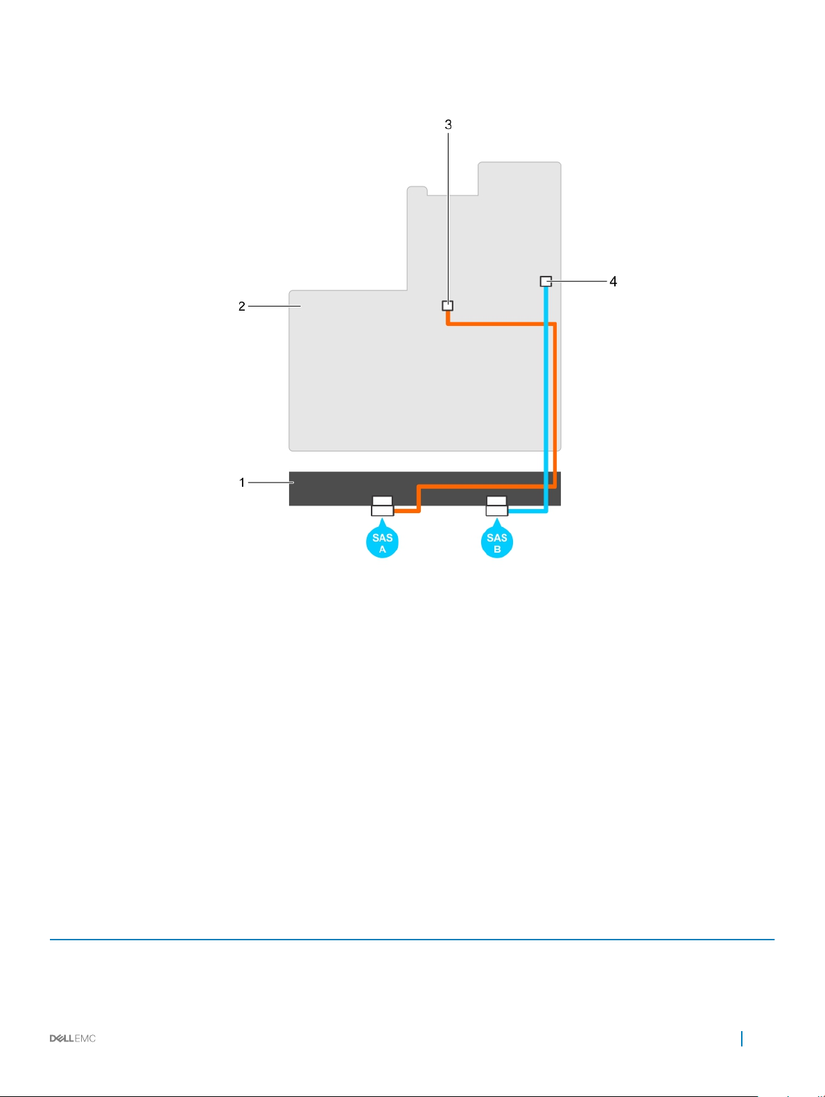
Figure 1. Cabling the S140 controller
1
backplane 2 system board
3 connector on the rst AHCI device (J_SATA A) 4 connector on the second AHCI device (J_SATA B)
Disk connectivity for AHCI devices
The S140 controller supports systems with up to two AHCI devices. For systems with two AHCI devices, the rst AHCI device connects
the drives from ports 0–5 and the second AHCI device connects the drives from ports 6–13.
The following table provides information about the disks connectivity to the AHCI devices supported on the 14th generation PowerEdge
systems.
Table 7. Disk connectivity for AHCI devices
Chipset Platform AHCI device 1 AHCI device 2
Intel C621 (C620 series
chipset)
PowerEdge R640, R740, R740xd, R940, and C6420 0-5 6-13
Cabling the drives for S140 19
Page 20
BIOS Conguration Utility
The BIOS Conguration Utility, also known as Ctrl+R or Option ROM (OPROM), is a storage management application integrated into the
System BIOS accessible using F2 during system boot, which congures and maintains RAID disk groups and virtual disks on SATA drives.
The BIOS Conguration Utility (Ctrl+R) is independent of the operating system.
NOTE: Use the Ctrl+R for initial setup and disaster recovery. You can use advanced features through OpenManage storage
management applications.
NOTE: Conguring NVMe PCIe SSDs is not supported using the BIOS conguration
utility.
NOTE: Ensure that you use only the S140 UEFI conguration utility to congure the NVMe PCIe SSDs during preboot. To enable
RAID mode for NVMe PCIe SSDs, see Setting the NVMe PCIe SSDs to RAID mode .
NOTE: RAID conguration using OPROM is not supported on systems with the NVMe PCIe
SSD.
The following sections provide information about using the Ctrl+R. For more information, see the online help option by pressing F1 in the
Ctrl+R.
The table below indicates the tasks that are supported or not supported by the PERC S140 at the Ctrl+R.
5
Table 8. BIOS
PERC S140 tasks Supported by S140
Enable alarm No
Disable alarm No
Quiet alarm No
Test alarm No
Set check consistency rate No
Rescan controller Yes
Create virtual disk Yes
Topics:
• Entering the BIOS conguration utility
• Exiting the BIOS Conguration Utility
• Initializing the physical disks
• Creating the virtual disks
• Deleting the virtual disks
• Swapping two virtual disks
• Managing the hot spare disks
• Viewing the physical disks details
• Viewing the virtual disks details
Conguration Utility (Ctrl+R) Tasks
20 BIOS Conguration Utility
Page 21

• Rescan disks
• Controller Options
• Continue to boot
Entering the BIOS conguration utility
1 Turn on the system.
2 While the system starts up, press Ctrl+R to boot to the BIOS conguration utility.
CAUTION: If the SATA controller is not set to RAID Mode, data might be destroyed. Ensure that you backup all data
before changing modes.
NOTE: If the BIOS Conguration Utility <Ctrl><R> does not appear and your system uses a PERC S140, press F2 to
access the system BIOS. In the SATA Settings eld, ensure that SATA controller is set to RAID Mode. If the settings are
correct and the BIOS Conguration Utility <Ctrl><R> does not appear, contact Dell support at dell.com/support.
Exiting the BIOS Conguration Utility
1 Press Esc in any menu screen.
A dialog box is displayed to conrm your choice.
2 Select C to exit or press Esc to cancel.
Initializing the physical disks
New physical disks must be converted to RAID capable disks before they can be used. When you convert a disk to a RAID capable disk, the
controller conguration information is written to the physical disk.
Physical disks with the following status can be initialized:
• Non-RAID — A physical disk that was congured by a non-PERC S140.
• Ready — Contains no stored data but has PERC S140 conguration information.
: Physical disks that are online cannot be converted to Non-RAID or RAID capable disks.
NOTE
1 Enter the BIOS conguration utility. See Entering the BIOS conguration utility.
2 In the Main Menu eld use the arrow keys to select the Initialize Physical Disks option.
3 Press Enter.
The Initializing the physical disks screen is displayed.
Converting to RAID disks
WARNING
1 Enter the BIOS conguration utility. See Entering the BIOS conguration utility.
2 Use the arrow keys to select Initializing the physical disks menu and press Enter.
3 Select Convert to RAID disk and press Enter.
4 Press C to continue.
5 In the Physical Disks menu, use the arrow keys to move between the physical disks and press Insert to select the desired physical
disk.
6 Press Enter.
The selected physical disk is converted to a RAID capable disk.
: You may lose data while converting a disk to a RAID disk.
Conguration Utility 21
BIOS
Page 22
Converting to Non-RAID disks
WARNING: You may lose data while converting a disk to a Non-RAID disk.
1 Enter the BIOS conguration utility. See Entering the BIOS conguration utility.
2 Use the arrow keys to select Initializing the physical disks menu and press Enter.
3 Select Convert to Non-RAID disk and press Enter.
4 Press C to continue.
5 In the Physical Disks menu, use the arrow keys to move between the physical disks and press Insert to select the desired physical
disk.
6 Press Enter.
The selected physical disk is converted to Non-RAID disks.
Creating the virtual disks
1 Enter the BIOS Conguration Utility. See Entering the BIOS conguration utility.
2 Select Create Virtual Disks from the Main Menu screen and press <Enter>.
NOTE: The S140 controller supports a maximum of 16 virtual disks per physical disk. You cannot modify any feature
settings in UEFI or OPROM if the number of virtual disks exceeds the maximum limit of 16. For more information about
troubleshooting this issue, see Unable to modify any feature settings in UEFI or OPROM.
3 In the Physical Disks eld, select the physical disk on which you want to create a virtual disk:
a To select a physical disk, press Insert.
b After selecting the physical disk to be included in the virtual disk, press Enter.
4 In the User Input eld, use the arrow keys to select a virtual disk type (RAID level) and press Enter.
5 Select a size for the virtual disk, depending on the available free space of the physical disks and press Enter.
6 In the User Input eld, select a Caching Mode. Press Enter.
7 Press C to conrm that you want to create the virtual disk.
Selecting virtual disk sizes while creating a virtual disk
To create a virtual disk size of < 2.199 TB:
1 Use the Page Up or Page Down keys to select a size displayed incrementally, or use the up arrow or down arrow keys to select a size
displayed decrementally.
2 Continue with Creating the virtual disks.
To create a virtual disk size of > 2.199 TB:
1 Press the Page Up or the up arrow key to increase the virtual disk size. At the maximum size, a dialog box is displayed in the User
Input eld. It inquires if you want to limit the size of the virtual disk or exceed the normal maximum size.
2 Press Esc to create a larger virtual disk.
3 Press the Page Up or the up arrow key until the desired or maximum available size has been attained.
4 Continue with Creating the virtual disks.
Deleting the virtual disks
1 Enter the BIOS Conguration Utility. See Entering the BIOS conguration utility.
2 In the Main Menu screen, select Deleting Virtual Disk using the arrow keys and press Enter.
22
BIOS Conguration Utility
Page 23

3 Select each virtual disk in the Virtual Disks eld that you want to delete. Press Insert to conrm each selection.
4 Press Enter.
CAUTION: Deleting a virtual disk permanently destroys all data that is on the virtual disk, as well as the virtual disk
itself. This action cannot be undone.
5 Press C to conrm the deletion.
NOTE: When a degraded or a failed virtual disk from one system is added to another system, and if the number of
virtual disks exceeds the maximum limit of 16, you cannot delete the virtual disks that are in the Normal or Ready state.
Swapping two virtual disks
1 Enter the BIOS Conguration Utility. See Entering the BIOS conguration utility.
2 In the Main Menu screen, select the Swapping Two Virtual Disks and press Enter.
3 Use the arrow keys to highlight a virtual disk at the Virtual Disk eld. Press Insert.
4 Use the arrow keys to highlight another virtual disk. Press Insert.
5 Press Enter to swap the virtual disks.
NOTE: Only two virtual disks can be swapped at a time.
NOTE: When you create up to 16 virtual disks and swap the virtual disks using the BIOS Conguration Utility, the order
of the virtual disk in option ROM (OPROM) appears dierent from the order of the virtual disk in operating system.
Managing the hot spare disks
Manage Hot Spare(s) screen enables you to assign or unassign a global or dedicated hot spare(s).
1 Enter the BIOS Conguration Utility. See Entering the BIOS conguration utility.
2 In the Main Menu screen, use the arrow keys to select Manage Hot Spare(s) and press <Enter>.
The Manage Hot Spare(s) screen display:
• global hot spare disks
• dedicated hot spare disks
Assigning the global hot spare disks
A global hot spare disk is a backup physical disk that can be used by any redundant virtual disk. It is not assigned (dedicated) to any specic
virtual disk. Virtual disks can typically be rebuilt by using a global spare disk, as long as the global hot spare is not already part of the virtual
disk and has enough available capacity. Unlike a dedicated hot spare, a global hot spare can be assigned at anytime, even while tasks are
running on virtual disks.
: A hot spare can be created only if a physical disk is in the Ready or Normal state in the Physical Disks eld. If the physical
NOTE
disk is in the Online state, the disk is being used by a virtual disk and cannot be selected as a hot spare.
Perform the following procedure to assign a global hot spare disk:
1 Enter the BIOS Conguration utility. See Entering the BIOS conguration utility.
2 In the Main Menu screen, select the Manage Hot Spare and press <Enter>.
3 Select Assign Global Hot Spare(s). Press <Enter>.
4 Use the up or down arrow key to select a physical disk(s) to be used as a global hot spare(s). Press <Insert>.
5 Press <Enter> to add the global hot spare.
6 Press the <C> key to conrm the action.
Conguration Utility 23
BIOS
Page 24

Assigning the dedicated hot spare disks
A dedicated hot spare is a backup physical disk for the redundant virtual disk to which it is assigned. The physical disk that is used as a
dedicated hot spare cannot be a member of an existing virtual disk. When the hot spare is activated, it becomes the receptacle for the data
from the failed physical disk member of the volume, without interrupting the system or requiring your intervention. A dedicated hot spare
can be assigned to any redundant virtual disk, and up to four hot spares can be assigned to a virtual disk. A dedicated hot spare cannot be
assigned while a task is running on the virtual disk.
NOTE: A virtual disk is marked Failed or Degraded if a physical disk reports a Failed state, or if the SAS/SATA cable to the
physical disk or power cable is disconnected.
NOTE: If a virtual disk with an assigned dedicated hot spare is deleted, the dedicated hot spare is also deleted and the physical
disk state changes to the Ready state.
Perform the following procedure to assign a dedicated hot spare disk:
1 Enter the BIOS conguration utility. See Entering the BIOS conguration utility.
2 In the Main Menu screen, select the Manage Hot Spare and press Enter.
3 Select Assign Dedicated Hot Spare. Press Enter.
4 Use the up or down arrow key to select a physical disk for use as a dedicated hot spare and press Insert.
5 Press Enter to add the dedicated hot spare.
6 Press the C key to conrm the action.
Unassign hot spare disks
1 Enter the BIOS Conguration utility. See Entering the BIOS conguration utility.
2 In the Main Menu screen, select the Manage Hot Spare and press Enter.
3 Select Unassign Hot Spare. Press Enter.
4 Use the up or down arrow key to select the physical disk to delete as a hot spare.
5 Press Insert. To delete the hot spare, press Enter
6 Press the C key to conrm the action.
Viewing the physical disks details
1 Enter the BIOS Conguration Utility. See Entering the BIOS conguration utility.
2 In the Main Menu screen, select View Physical Disk Details and press <Enter>.
3 Use the arrow keys to choose a physical disk.
4 The following details of the physical disks are displayed:
a Physical disk number
b Channel number
c Physical disk size
d Physical disk status: Non-RAID/Ready/Online
e Amount of free space
f Manufacturer and model number
g World Wide Address
h SATA Cache Policy (Enabled or Disabled)
i S.M.A.R.T. State: Error (if a disk with a S.M.A.R.T. error is discovered)
5 Press <Esc> to return to the main window.
24
BIOS Conguration Utility
Page 25

Viewing the virtual disks details
1 Enter the BIOS Conguration Utility. See Entering the BIOS conguration utility.
2 In the Main Menu screen, select View Virtual Disk Details and press <Enter>.
3 Use the arrow keys to choose a virtual disk.
4 The following details of the virtual disks are displayed:
a Virtual disk number
b RAID Level
c Size
d Status (Read Ahead/Write Back, No Read Ahead/Write Back, Read Ahead/Write Through, No Read Ahead/Write Through)
5 Press <Esc> to return to the main window.
NOTE: The Physical Disks eld indicates the physical disks that are in the virtual disk, highlighted by green
text.
Rescan disks
This option allows you to view the list of existing Physical and Virtual disks.
1
1 Enter the Dell PERC S140 Conguration Utility. See Entering the DELL PERC S140 Conguration Utility.
2 Click Controller Management > Rescan Disks.
The Rescan Disks screen is displayed. It provides information about the latest physical disk and virtual disk congurations.
NOTE: The Rescan disks option may take from 10 to 20 seconds to display the list of disks, depending on the number of
disks available in the system.
Controller Options
The Controller Options feature helps you to enable the BIOS Stop on Error option. The boot process pauses when Pause if... is enabled
and a virtual disk becomes Degraded or has Failed. Press <Enter> to continue booting.
View the error message on the window. If Pause... is OFF, the error message is displayed briey, but the system continues to boot.
1 Enter the BIOS Conguration Utility. See Entering the BIOS Conguration Utility.
2 In the Main Menu screen, use the arrows to select the Controller Options.
3 In the Controller Options eld, use the up or down arrow keys to scroll to the desired controller option.
a Pause if Degraded
When ON, the BIOS stops booting when a degraded virtual disk is found.
Press <Enter> to toggle between ON and OFF.
b Pause if Failed
When ON, the BIOS stops booting when a failed virtual disk is found.
Press <Enter> to toggle between ON and OFF.
c Manage Physical Disk Write Cache
• If the option is set to Default:
• The physical disk write cache policy is enabled for SSDs and HDDs of bandwidth 3 Gbps.
• The physical disk write cache feature is disabled for HDDs of bandwidth 6 Gbps.
• If the option is set to Enable, the feature is enabled on the disk selected.
• If the option is set to Disable, The feature is disabled on the disk selected.
4 Press Esc to return to the main window.
Conguration Utility 25
BIOS
Page 26

Continue to boot
1 Enter the BIOS Conguration Utility. See Entering the BIOS conguration utility.
2 In the Main Menu screen, use the arrows to select the Continue to Boot.
The system restarts normally.
26 BIOS Conguration Utility
Page 27
6
UEFI RAID conguration utility
The Unied Extensible Firmware Interface (UEFI) RAID conguration utility is a storage management application integrated into the System
BIOS F2. It is used to congure and manage RAID, virtual disks, and physical disks. This utility is independent of the operating system.
NOTE: The following sections provide information about using the UEFI RAID conguration utility. For more information, see the
online help option in the UEFI RAID conguration utility.
NOTE: Ensure that you use only the S140 UEFI conguration utility to congure the NVMe PCIe SSDs during preboot. To enable
RAID mode for NVMe PCIe SSDs, see Setting the NVMe PCIe SSDs to RAID mode
NOTE: Use the UEFI RAID conguration utility for initial
setup.
Topics:
• Entering the DELL PERC S140 Conguration Utility
• Exiting the DELL PERC S140 Conguration Utility
• Controller management
• Virtual disk management
• Physical disk management
Entering the DELL PERC S140 Conguration Utility
1 Turn on the system.
2 While the system starts up, press <F2> to enter System Setup.
The list of menu items in the System Setup Main Menu screen is displayed.
3 Click Device Settings.
Device Settings lists the NIC ports and all the options of the S140 conguration utility.
To access the management menu for the controller, use the arrow keys or the mouse.
NOTE
: For more information on all the options, click Help in the top right-hand corner of the browser screen. Help
information for individual option menus can also be viewed by scrolling down on each option.
NOTE: Some of the options within the UEFI RAID conguration utility are not present if the controller does not support
the corresponding feature. Options may also be grayed out if the feature is not supported in existing conguration.
4 Click Dell PERC S140 Conguration Utility.
Displays the list of Conguration Options:
Table 9.
Conguration Options
Controller Management allows you to congure, manage, and view the controller properties.
Virtual Disk Management allows you to congure, manage, and view the virtual disk properties.
UEFI RAID conguration utility 27
Page 28
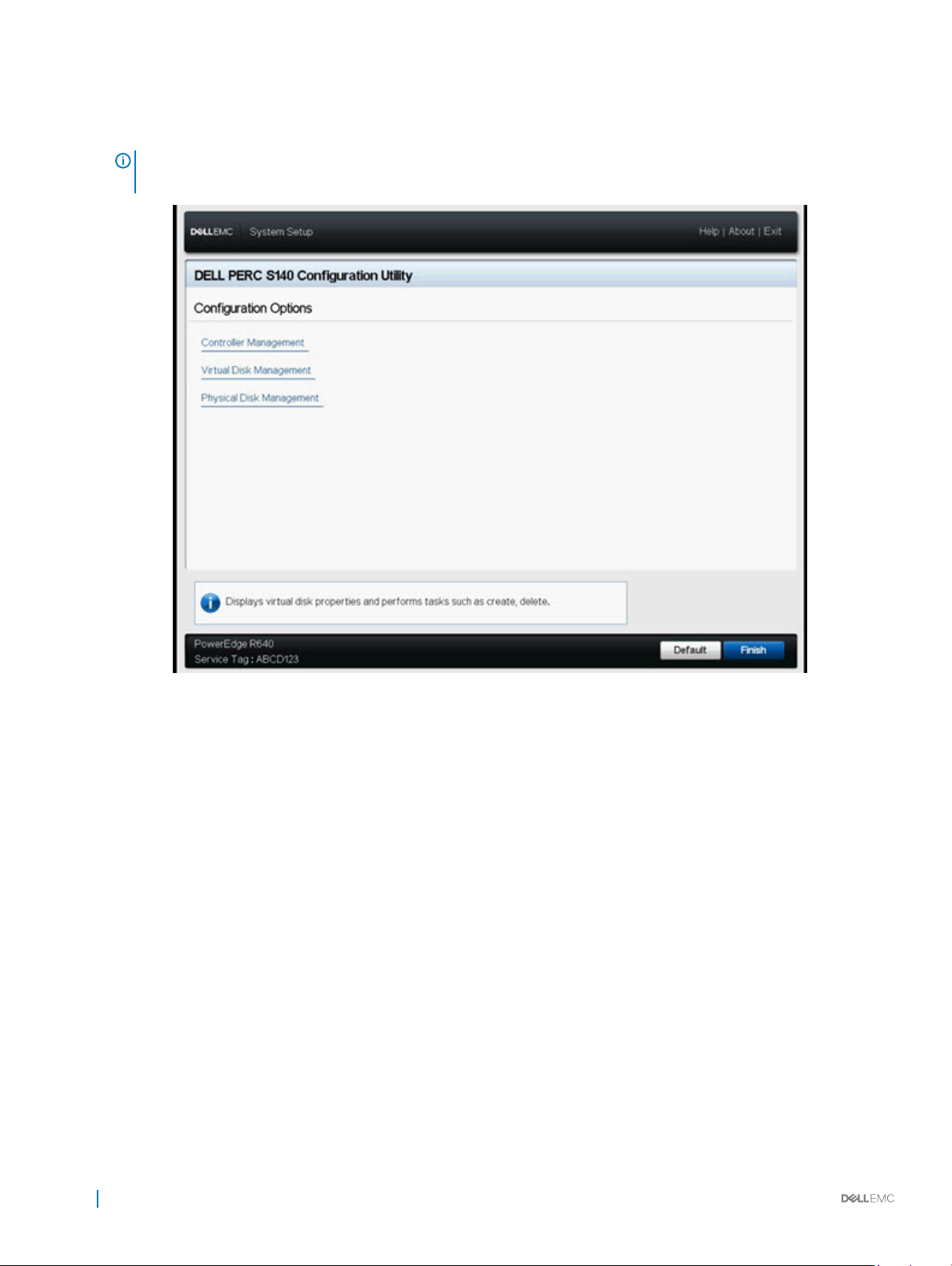
Physical Disk Management allows you to congure, manage, view and perform varied operations on the physical disk
properties.
NOTE: Loading default settings in this page by clicking on Default button will not cause any changes in the controller
settings.
Figure 2. Dell PERC S140 Conguration Utility
Exiting the DELL PERC S140 Conguration Utility
To exit the utility and return to the System Setup screen, click Finish in the bottom-right corner on the screen.
Controller management
Viewing the controller properties
The View Controller Information screen allows you to view your controller and rmware properties.
In the System Setup Main Menu, click Device Settings > Dell PERC S140 Conguration Utility > Controller Management > View
Controller Information.
The table explains the View Controller Information screen details:
Table 10. View Controller Information
Menu Item Description
PCI ID Displays the PCI ID
28 UEFI RAID conguration utility
Page 29
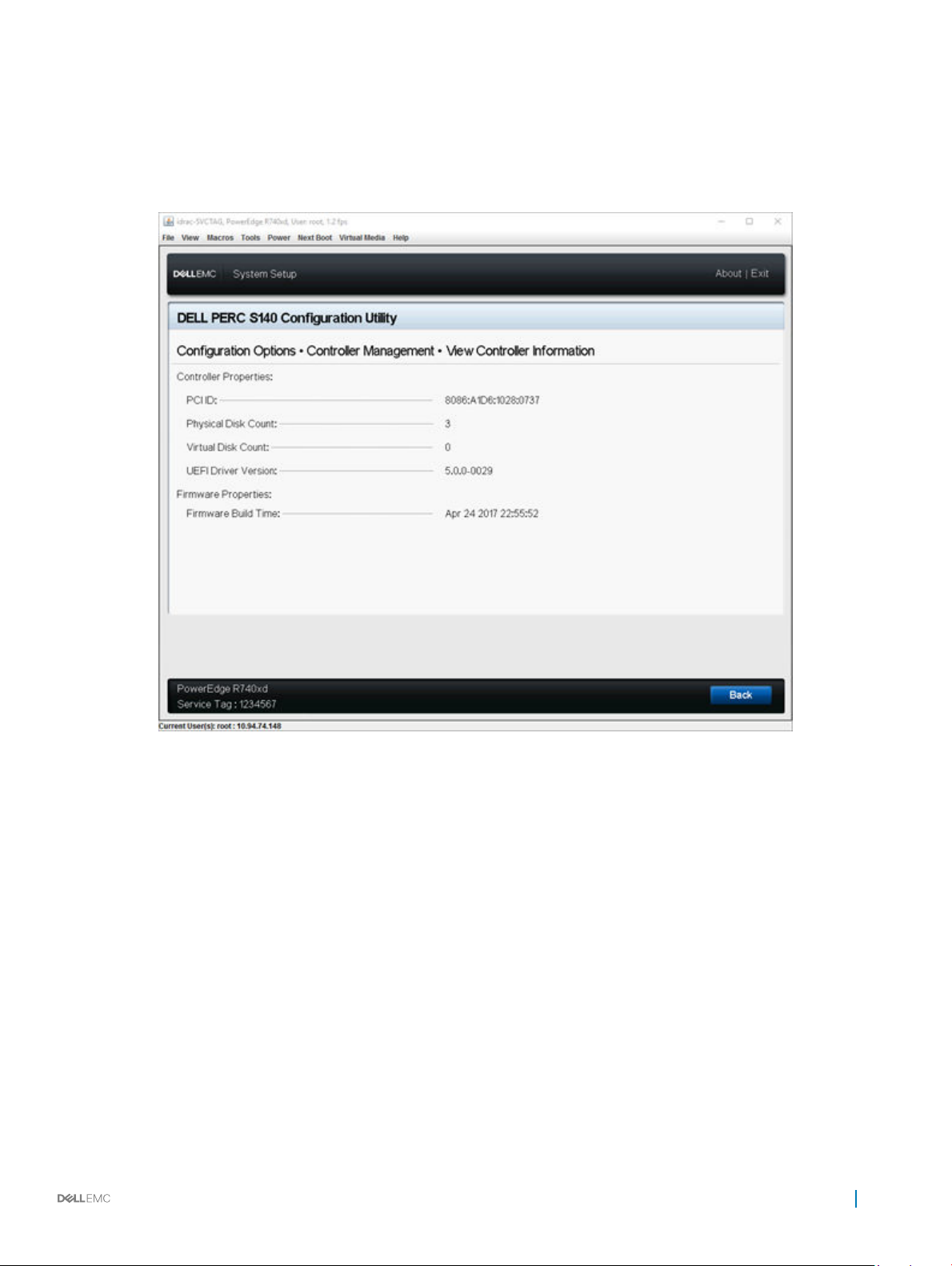
Physical disk Count Displays the total number of physical disks available on the system
Virtual Disk Count Displays the total number of virtual disks available
UEFI Driver Version Displays the UEFI driver version installed on the system
Firmware Build Time Displays the time and date the rmware was last updated.
Figure 3. View Controller Information Screen
Changing the boot order of the virtual disks
Set Bootable Device allows you to change the boot order of the virtual disks.
1 Enter the Dell PERC S140 Conguration Utility. See Entering the DELL PERC S140 Conguration Utility.
2 Click Controller Management > Change Controller Properties.
3 Click Set Bootable Device.
A Change Order dialog box displays the list of virtual disks available.
4 Use the arrow keys to set a virtual disk and + or – to change the order of the virtual disks that need to be booted rst.
5 Click Ok.
The changes to the boot order of the virtual disks are displayed.
UEFI RAID
conguration utility 29
Page 30

Stopping the system from booting if there is a critical BIOS error
The Change Controller Properties screen allows you to either enable or disable the option to stop the system from booting if there is any
critical BIOS error requiring manual intervention.
1 Enter the Dell PERC S140 Conguration Utility. See Entering the DELL PERC S140 Conguration Utility.
2
Click Controller Management > Change Controller Properties.
3 You can either enable or disable the Enable BIOS Stop On Error.
Converting a physical disk to a Non-RAID disk
1 Enter the Dell PERC S140 Conguration Utility. See Entering the DELL PERC S140 Conguration Utility.
2 Click Controller Management > Convert to Non-RAID Disk.
3 Select the interface type.
4 Select the physical disks. Click Check All to select all the disks available.
5 Click Apply Changes.
Converting physical disk to RAID capable disk
1 Enter the Dell PERC S140 Conguration Utility. See Entering the DELL PERC S140 Conguration Utility.
2 Click Controller Management > Convert to RAID Capable Disk.
3 Select the RAID type.
NOTE
: RAID type will not be available if a RAID is already congured. To enable RAID type, convert the disk to a non
RAID disk (see Converting physical disk to Non-RAID disk) and then convert them back to RAID capable disk.
4 Select disk interface type.
5 Select the physical disk to convert to a RAID capable disk. If you wish to select all the available disks, select Check All.
6 Click Apply Changes to submit the changes selected.
Rescan disks
This option allows you to view the list of existing Physical and Virtual disks.
1
1 Enter the Dell PERC S140 Conguration Utility. See Entering the DELL PERC S140 Conguration Utility.
2 Click Controller Management > Rescan Disks.
The Rescan Disks screen is displayed. It provides information about the latest physical disk and virtual disk congurations.
NOTE
: The Rescan disks option may take from 10 to 20 seconds to display the list of disks, depending on the number of
disks available in the system.
30
UEFI RAID conguration utility
Page 31

Virtual disk management
This section allows you to create, manage and delete virtual disks. You can also view and modify some properties of the associated physical
disk.
Conguring Windows RAID
NOTE: To enable RAID mode for NVMe PCIe SSDs, see Setting the NVMe PCIe SSDs to RAID mode .
1 Enter the Dell PERC S140 Conguration Utility. See Entering the DELL PERC S140 Conguration Utility.
2 Click Controller Management→Convert to RAID Capable Disk.
3 Select the RAID typeWindows RAID.
4 Select the Interface Type.
The options are SATA and NVMe.
5 Select the physical disk and click Apply Changes.
A conrmation screen is displayed.
6 Click Yes to continue.
7 Click Back to return to the conguration options screen.
8 After converting the physical disks, click the Virtual Disk Management in the Conguration Options screen.
NOTE
: Conguring RAID 5 on NVMe PCIe SSDs is not
supported.
9 Click Create Virtual Disks.
10 Click Select the Physical Disk.
11 Select the interface type, media type, sector size, and the physical disks.
12 Click Apply Changes.
13 Enter the virtual disk size and select the Virtual Disk Size Unit.
14 Select the Read Cache Policy.
15 Select the Write Cache Policy.
16 Select the Physical Disk Write Cache.
17 Click Create Virtual Disk.
The virtual disk is ready.
Conguring Linux RAID
: The S140 controller supports RHEL 7.3, RHEL 7.4 and SLES 12 SP2. The Linux installer fails to detect the virtual disks if
NOTE
the RHEL 7.1 or earlier or SLES 11 SP3 or earlier are installed.
NOTE: The Linux RAID feature is supported on all the 14th generation systems.
NOTE: For Linux RAID, ensure that the number of physical disks does not exceed 10.
NOTE: To enable RAID mode for NVMe PCIe SSDs, see Setting the NVMe PCIe SSDs to RAID mode .
1 Enter the Dell PERC S140 Conguration Utility. See Entering the DELL PERC S140 Conguration Utility.
2 Click Controller Management → Convert to RAID Capable Disk.
3 Select the RAID type as Linux RAID.
UEFI RAID
conguration utility 31
Page 32
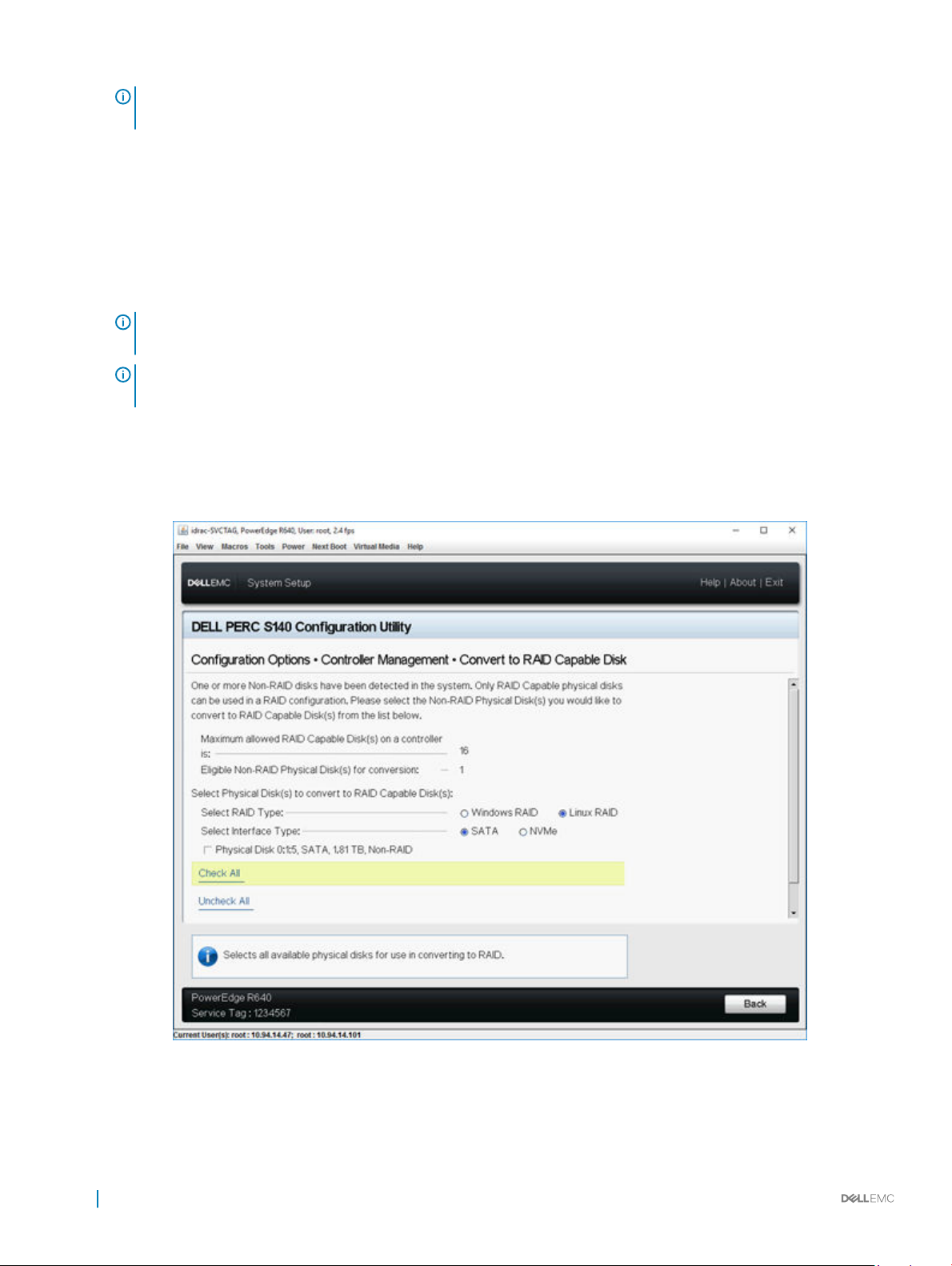
NOTE: If the option to choose Linux RAID is disabled, convert the disk to a non-RAID disk(see Converting physical disk
to Non-RAID disk) and then convert it back to RAID capable disk (see Converting physical disk to RAID capable disk).
4 Select the Interface Type.The options are SATA and NVMe.
5 Select the physical disk and click Apply Changes.
A conrmation screen is displayed.
6 Click Yes to continue.
7 Click Back to return to the conguration options screen.
8 After converting the physical disks, click the Virtual Disk Management in the Conguration Options screen, and click Create Virtual
Disks.
9 Select the required Linux operating system.
NOTE: If you select RHEL as the operating system, the entire physical disk space is used in the Virtual Disk Size eld.
With RHEL, you can create virtual disks only on the entire physical disk space.
NOTE: If you select SLES as the operating system, you can create virtual disks on both full and partial physical disk
space.
10 Click Select the Physical Disk.
11 Select the interface type, media type, sector size, and the physical disks.
12 Click Apply Changes.
13 Click Create Virtual Disk.
The virtual disk is ready.
Figure 4. Convert to Linux RAID selection page
32
UEFI RAID conguration utility
Page 33

Mixed RAID conguration
If your system detects mixed RAID congurations with both Windows and Linux RAID disks, then the S140 UEFI conguration utility
displays the mixed conguration screen where you are encouraged to perform the following tasks:
1 To convert the Linux RAID disks:
a In the WARNING: MIXED CONFIGURATION screen, select Windows RAID conguration.
b Select the physical disks with Linux RAID conguration listed, and click the link CONVERT TO NON-RAID. If you do not want to
convert the disks to non-RAID, remove the physical disks with Linux RAID congurations from the system.
2 To convert the Windows RAID disks:
a In the WARNING: MIXED CONFIGURATION screen, select Linux RAID conguration.
b Select the physical disks with Windows RAID conguration listed, and click the link CONVERT TO NON-RAID. If you do not
want to convert the disks to non-RAID, remove the physical disks with Windows RAID congurations from the system.
NOTE: The S140 controller does not support a mixed RAID conguration. If the mixed RAID conguration with both Windows and
Linux RAID disks is detected, then you cannot perform any further tasks until you clear the physical disks or convert the physical
disks.
Manage virtual disk properties
The Manage Virtual Disk Properties screen allows you to modify the physical disk write cache policy and view the associated physical disk
and its properties and policies.
In the System Setup Main Menu, click Device Settings > Dell PERC S140 Conguration Utility > Virtual Disk Management > Manage
Virtual Disk Properties
.The table explains the Manage Virtual Disk Properties screen details:
Table 11. Virtual Disk Properties
Menu Item Description
Select Virtual Disk Allows you to select the virtual disk from the drop-down menu
Virtual Disk Properties Displays the ID, RAID Level, Status, Capacity, and the Sector Size of the virtual disk
Virtual Disk ID Displays the ID for the virtual disk
RAID Level Displays the RAID level of the virtual disk
Virtual Disk Status Displays the virtual disk status
Virtual Disk Capacity Displays the capacity of the virtual disk
Sector Size Displays the sector size enabled for the virtual disk
Virtual Disk Policies Displays the read and write cache policies of the virtual disk and the write cache policy of the
associated physical disk
Read Cache Policy Displays the read cache policies associated with the virtual disk
Write Cache Policy Displays the write cache policies associated with the virtual disk
Physical Disk Write Cache Displays the status of the physical disk write cache policy
Modify the Physical Disk Write Cache Allows you to modify the physical disk write cache policy settings
NOTE: If you have Linux RAID congured on the system, then you cannot modify any
settings in this eld.
Physical Disk Write Cache Allows you to change the physical disk write cache policy settings. The options are Default,
Enable, and Disable.
NOTE: If you have Linux RAID congured on the system, then you can only view the
physical disk write cache setting
UEFI RAID conguration utility 33
Page 34

Apply Disk Write Cache Settings Allows you to apply the new write cache policy for the Physical disk.
View Associated Physical Disk Clicking this link displays the physical disk that is associated with the selected virtual disk
Viewing virtual disks properties and policies
The View Virtual Disk Properties screen allows you to view the virtual disk properties and the policies.
In the System Setup Main Menu, click Device Settings > Dell PERC S140 Conguration Utility > Virtual Disk Management > View
Virtual Disk Properties.
The table explains the View Virtual Disk Properties screen details:
Menu Item Description
Select Interface
Type
Select Virtual Disk Allows you to select the virtual disk from the drop-down menu.
Virtual Disk
Properties
Virtual Disk ID Displays the virtual disk ID.
RAID level Displays the RAID level associated with the virtual disk.
Virtual Disk Status Displays the status of the virtual disk.
Virtual Disk
Capacity
Sector Size Displays the sector size enabled.
Virtual Disk Policies
(SATA drives only)
Read Cache Policy
(SATA drives only)
Write Cache Policy
(SATA drives only)
Allows you to select the disk interface type. The options are SATA and NVMe.
NOTE: Virtual disk in failed status are only listed in Manage Virtual Disk Properties screen.
Displays the ID, RAID Level, Status, Capacity, and the Sector Size of the virtual disk.
Displays the capacity of the virtual disk.
Displays the read and write cache policies of the virtual disk and the write cache policy of the associated physical
disk.
Displays the read cache policies associated with the virtual disk.
Displays the write cache policies associated with the virtual disk.
Physical Disk Write
Cache (SATA drives
only)
Associated Physical
Disks
34 UEFI RAID conguration utility
Displays the physical disk which is associated with the specic virtual disk.
Displays the associated physical disk's properties.
Page 35
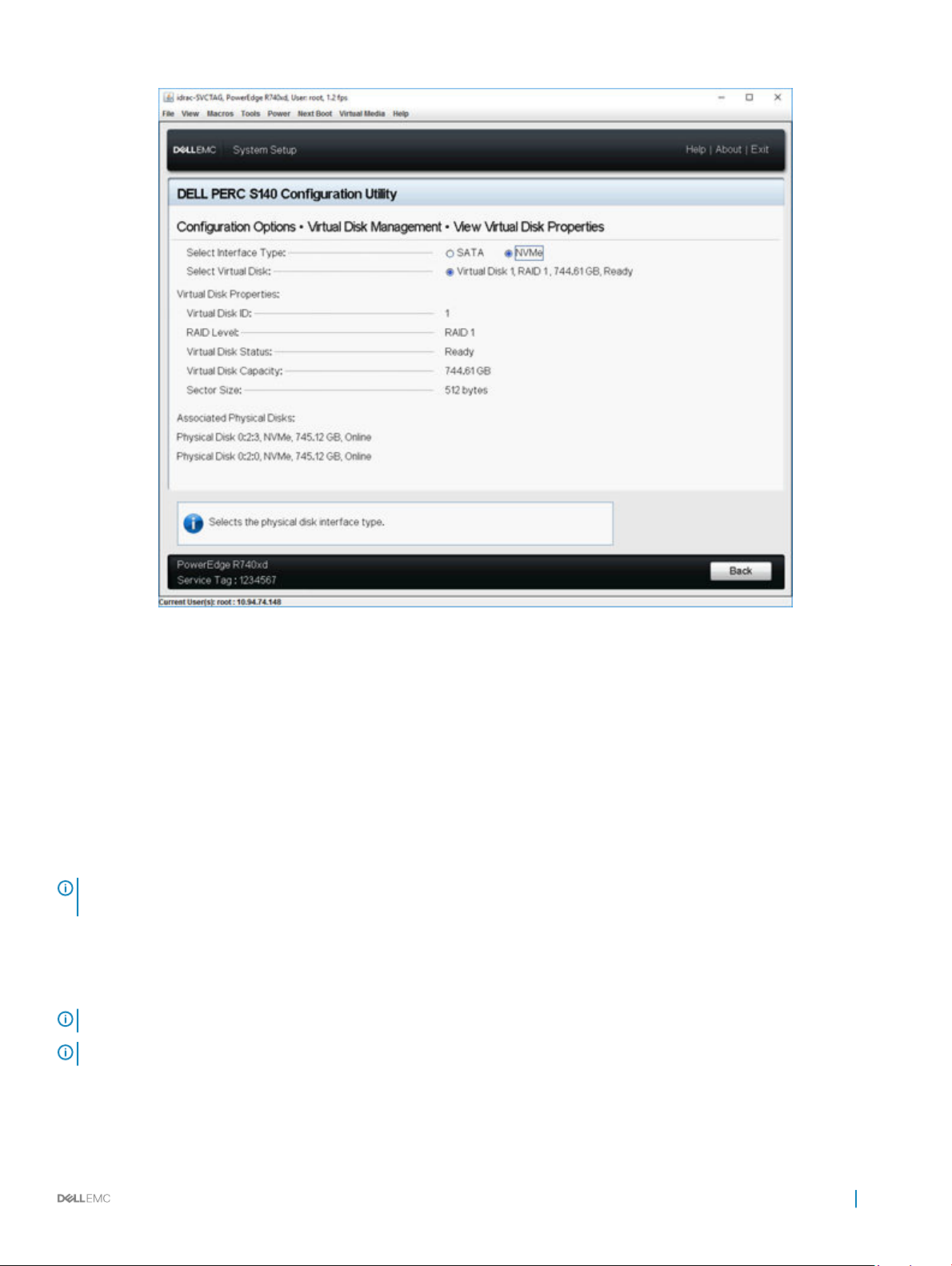
Figure 5. Virtual Disk Properties Screen
Deleting a virtual disk
1 Enter the Dell PERC S140 Conguration Utility. See Entering the DELL PERC S140 Conguration Utility.
2 Click Virtual Disk Management > Select Virtual Disk Operations.
3 Select a virtual disk that you want to delete from the drop-down menu.
4 Click Delete Virtual Disk.
5 Select Conrm and click Yes to continue.
The selected virtual disk is deleted.
NOTE
: When a degraded or a failed virtual disk from one system is added to another system, and if the number of virtual disks
exceeds the maximum limit of 16, you cannot delete the virtual disks that are in the Normal or Ready state.
Physical disk management
This section allows you to view, select and manage physical disks.
: NVMe PCIe SSDs may not be sorted by slot number or ID in the physical disk list.
NOTE
NOTE: Physical disk capacity displayed may be lower than the actual capacity.
UEFI RAID conguration utility 35
Page 36

Viewing physical disk properties
The View Physical Disk Properties screen allows you to view the properties of physical disk and also provides details about the associated
virtual disks.
In the System Setup Main Menu, click Device Settings > Dell PERC S140 Conguration Utility > Physical Disk Management > View
Physical Disk Properties. The table explains the View Physical Disk Properties screen details:
Table 12. View Physical Disk Properties
Menu Item Description
Select Interface Type Allows you to select the disk type, the options are SATA and NVMe.
Select Physical Disk Allows you to select the physical disks from the drop-down menu.
Physical Disk Properties Displays information about the physical disk properties.
Physical disk ID Displays the ID of the physical disk.
Form Factor Displays the form-factor of the physical disk.
State Displays if it is a RAID capable disk or a Non-RAID disk.
Size Displays the total storage space of the physical disk.
SMART status Displays if the SMART feature is enabled or disabled for the physical disk.
Revision Displays the revision.
Device Type Displays the device type.
Certied (SATA Drives only) Displays if the physical disk is Dell certied or not.
Connector Port (SATA Drives only) Displays the port number in which the SATA physical disk is installed.
Disk Write Cache (SATA Drives only) Displays if the disk cache is enabled or disabled.
Hot Spare Displays if the physical disk is assigned as a hot spare.
Available Space Displays the free space of the respective physical disk.
Used Space Displays the used space of the respective physical disk.
Device Protocol Displays if the protocol of the physical disks.
Media Type Displays the type of disk selected.
Disk Sector Size Displays the type of sector size enabled.
Negotiated Physical Disk Transfer speed
(SATA Drives only)
Dell Part Number Displays the part number of the physical disk.
Serial Number of Disk Displays the serial number of the physical disk.
Hardware Vendor Displays the information about the hardware vendor.
Model Number Displays the model number of the physical disk.
Manufacturing Date Displays the manufacturing date of the physical disk.
Associated Virtual Disks Displays the disk ID, RAID level, size and status of the associated virtual disk.
Displays the speed at which the data is transferred.
36 UEFI RAID conguration utility
Page 37
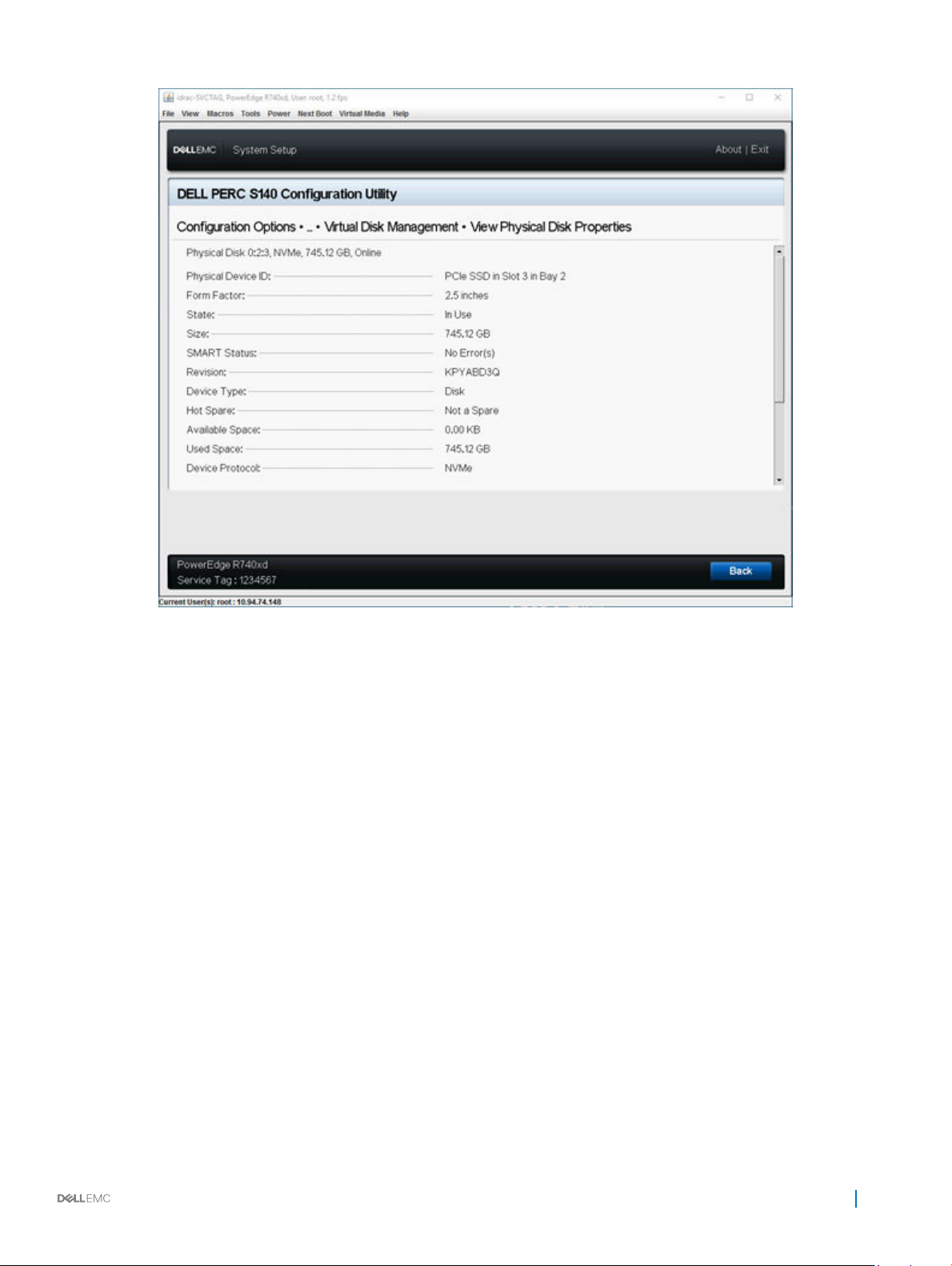
Figure 6. Physical Disk Properties Screen
Managing the physical disk write cache policy for SATA drives
Perform the following procedure to enable the physical disk write cache policy:
1 Enter the Dell PERC S140 Conguration Utility. See Entering the DELL PERC S140 Conguration Utility.
2 Click Physical Disk Management → Select Physical Disk Operations.
3 Click the link Manage Physical Disk Properties.
The Manage Physical Disk Properties screen is displayed.
4 Select one or multiple physical disk to apply the write cache policy.
5 Choose from the following physical disk write cache policies:
Physical disk
Description
write cache
policies
Default The physical disk write cache feature is enabled for:
• SSDs
• 3 Gbps HDDs
The physical disk write cache feature is disabled for 6 Gbps HDDs.
Enable The feature is enabled on the disk selected.
UEFI RAID conguration utility 37
Page 38
Physical disk
Description
write cache
policies
Disable The feature is disabled on the disk selected.
6 Click Apply to save the changes made.
NOTE: Ensure that you change the physical disk write cache policy of a global hot spare disk after rebuild to the write
cache policy of the last congured virtual disk.
NOTE: In the View Virtual Disk Properties screen, ensure that the physical disk write cache setting is consistent across
the physical disk associated with the virtual disk.
NOTE: If you have Linux RAID congured on the system, you cannot modify the physical disk write cache policy feature
settings.
NOTE: For more information about the physical disk write cache behavior, see the Troubleshooting your system section.
Assigning the global hot spare
1 Enter the Dell PERC S140 Conguration Utility. See Entering the DELL PERC S140 Conguration Utility.
2 Click Physical Disk Management > Select Physical Disk Operations.
3 Select the physical disk that is in the ready state from the drop-down menu.
4 Click the link Assign Global Hot Spares.
NOTE
: A global hot spare disk cannot be created if you have Linux RAID congured on the
system.
Unassign a global hot spare
: Unassigning a hotspare may place the data at risk in the event of a disk failure.
NOTE
1 Enter the Dell PERC S140 Conguration Utility. See Entering the DELL PERC S140 Conguration Utility.
2 Click Physical Disk Management > Select Physical Disk Operations.
3 Select a global hot spare disk from the drop-down menu.
4 Click the link Unassign Hot Spare.
Conrmation screen appears.
5 Click Yes to conrm.
Assigning the dedicated hot spare
WARNING
1 Enter the Dell PERC S140 Conguration Utility. See Entering the DELL PERC S140 Conguration Utility.
2 Click Virtual Disk Management > Manage Virtual Disk Properties.
3 Select the virtual disk that is in the ready state from the drop-down menu.
4 Click Manage Dedicated Hot Spares
5 Select the physical disk that you want to be assigned as a dedicated hot-spare disk.
6 Click the link Add Hot Spare Disk.
Conrmation screen appears.
: Assigning a disk as a hot spare will cause the data on the disk to be permanently deleted.
38
UEFI RAID conguration utility
Page 39
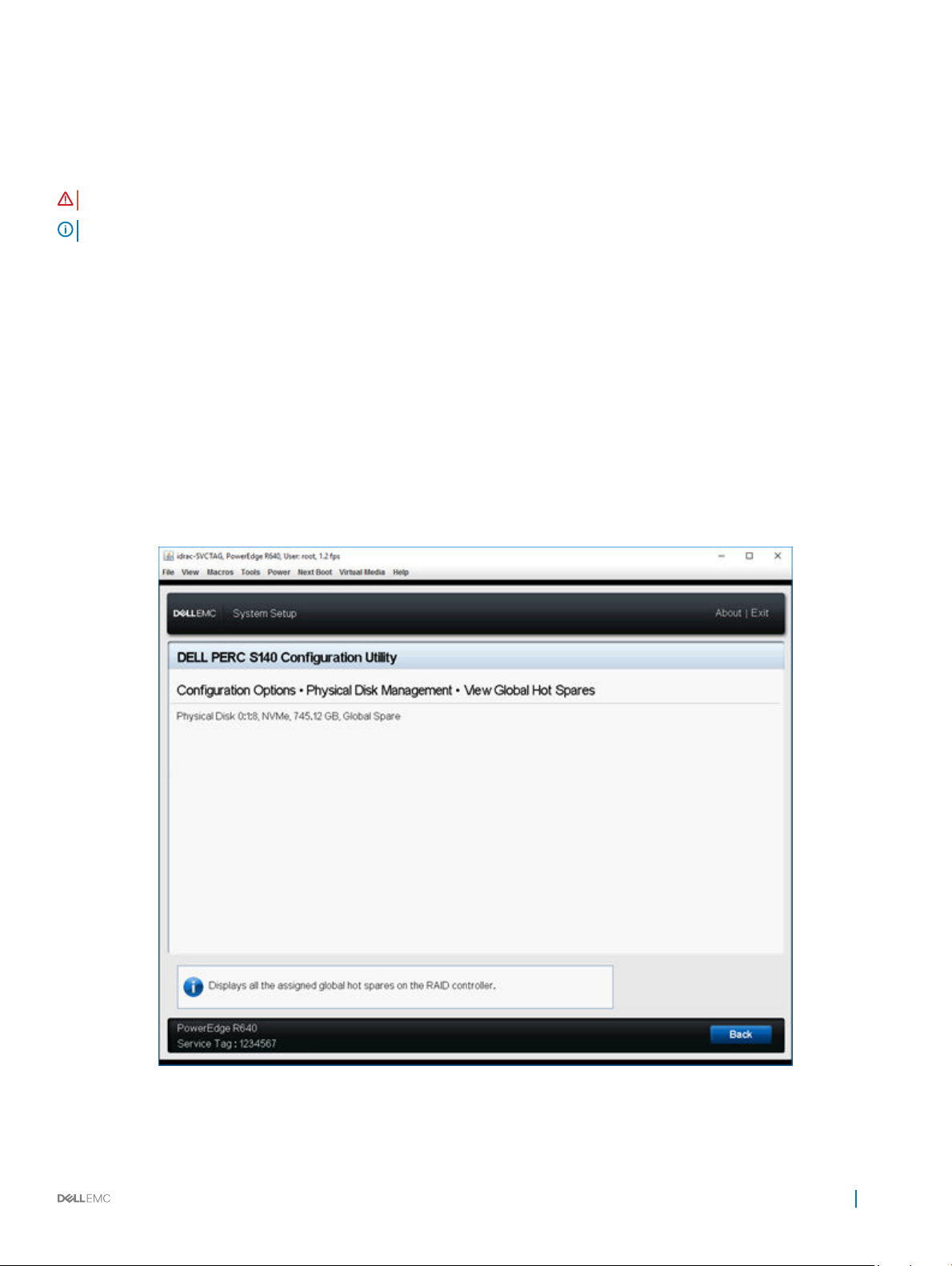
7 Select Conrm and click YES to complete the dedicated hot spare disk assignment.
Cryptographic erase
WARNING: Performing a cryptograph erase, causes permanent loss of data.
NOTE: Cryptographic erase is only supported on NVMe PCIe SSDs and ISE-capable SATA drives.
1 Enter the Dell PERC S140 Conguration Utility. See Entering the DELL PERC S140 Conguration Utility.
2 Click Physical Disk Management → Select Physical Disk Operations.
3 Select the Interface Type.
The options are SATA and NVMe.
4 Select the physical disk from the drop-down menu.
5 Click Cryptographic Erase.
6 Click Yes to start the cryptographic erase.
Viewing global hot spares
The View Global Hot Spares screen displays the physical disk assigned as global hot spare.
In the System Setup Main Menu, click Device Settings > Dell PERC S140 Conguration Utility > Physical Disk Management > View
Global Hot Spares.
Figure 7. View Global Hot Spares
UEFI RAID
conguration utility 39
Page 40
Installing the drivers
The PowerEdge RAID Controller (PERC) S140 requires software drivers to operate with supported operating systems. Which drives to
install depends on the type of the system and the operating system installed.
NOTE: To check operating system compatibility, see dell.com/support/manuals
NOTE: If the operating system is installed on a PERC or BOSS device, ensure that the software RAID OS driver is installed using
the Dell Update Package (DUP) while SATA and NVMe are in RAID mode while in BIOS settings.
Topics:
• Pre-installation requirements
• Creating the device driver media for Windows driver installation
Pre-installation requirements
Before you install the operating system:
7
• Read the Microsoft Getting Started document that shipped with your Windows operating system.
• Ensure that your system has the latest BIOS, rmware, and driver updates. If required, download the latest BIOS, rmware, and driver
updates from dell.com/support.
• Create a device driver media (USB drive, CD, or DVD).
Setting the SATA controller to RAID mode
1 Turn on the system.
2 When the Dell Power-On Self-Test (POST) screen is displayed, press F2.
3 When the Dell PowerEdge System window is displayed, scroll to SATA Settings and press Enter.
In the sub-screen, conrm that the SATA Controller is set to a RAID mode.
NOTE
: If necessary, use the space bar to change the setting.
4 Press Esc to exit.
5 Press Esc again.
Setting the NVMe PCIe SSDs to RAID mode
WARNING
NOTE: Ensure SATA settings is on RAID mode.
: Changing mode to RAID mode will cause a data loss in the NVMe PCIe SSD.
1 Turn on the system.
2 When the Dell Power-On Self-Test (POST) screen is displayed, press F2.
3 When the System Setup window is displayed, click System BIOS.
40 Installing the drivers
Page 41
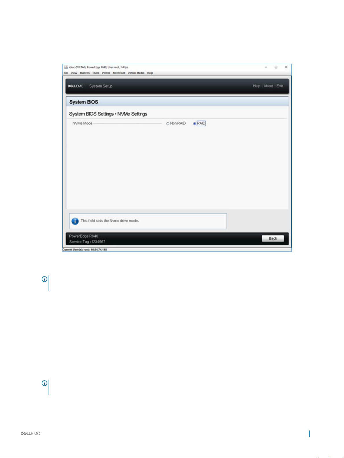
4 Click NVMe Settings.
5 Select RAID mode.
6 Click Back.
7 Click Finish.
Figure 8. NVMe Settings in BIOS
NOTE
: If you change the NVMe Mode setting from RAID to Non RAID, ensure that the NVMe driver (Microsoft or third-
party NVMe driver) is installed manually in the Windows environment.
Creating a virtual disk
For more information about creating a virtual disk, see Creating the virtual disks.
Checking PERC S140 options and the boot list priority.
1 In the Virtual Disks eld, ensure the bootable virtual disk is the rst virtual disk listed. If the bootable virtual disk is not the rst virtual
disk listed, see Swapping two virtual disks.
: If Non-RAID virtual disks are used (and appear in the Virtual Disks list), the Swap Two Virtual Disks option is
NOTE
enabled only if the system contains a RAID Capable physical disk.
2 Select Continue to Boot and press Enter.
Installing the drivers
41
Page 42
Creating the device driver media for Windows driver installation
Downloading drivers for PERC S140 from the Dell support website for all operating systems
1 Go to dell.com/drivers.
2 In the Product Selection section, enter the service tag of your system in the Service Tag or Express Service Code eld.
NOTE: If you do not have the service tag, select Automatically detect my Service Tag for me to allow the system to
automatically detect your service tag, or select Choose from a list of all Dell products to select your product from the
Product Selection page.
3 Select the Operating System, Category, Release Date, and Importance from the respective drop-down lists.
The drivers that are applicable to your selections are displayed.
4 Download the drivers that you require to a USB drive, CD, or DVD.
5 During the operating system installation, use the media that you created with the Load Driver option to load mass storage drivers. For
more information on reinstalling the operating system, see the operating system document at dell.com/operatingsystemmanuals.
NOTE: For systems with NVMe PCIe SSD, ensure the S140 driver is installed to discover the RAID disk in your operating
system environment.
NOTE: During the Windows OS installation using the onboard optical disk drive, while loading the S140 driver, a warning
message may appear:
and then click OK
a Click OK.
b Close the warning window.
c Click Install Now, and follow the instructions on the screen.
No new device drivers were found. Make sure the installation media contains the correct drivers,
, when SATA is in RAID mode. Perform the following steps to proceed with the installation:
Downloading drivers from the Dell Systems Service and Diagnostic Tools media for Windows
1 Insert the Dell Systems Service and Diagnostics Tools media in your system.
The Welcome to Dell Service and Diagnostic Utilities screen is displayed.
2 Select your system model and operating system.
For the list of supported operating systems, see Supported operating systems.
3 Click Continue.
4 From the list of drivers displayed, select the driver you require.
5 Select the self-extracting zip le and click Run.
: In Microsoft Windows Server 2012 R2, use the Dell Update Package(DUP)
NOTE
le.
6 Copy the driver to a CD, DVD, or USB drive.
Repeat this step for all the drivers you require.
7 During the operating system installation, use the media that you created with the Load Driver option to load mass storage drivers.
For more information on reinstalling the operating system, see the relevant section for your operating system.
42
Installing the drivers
Page 43

Troubleshooting your system
To get help with your Dell PowerEdge RAID Controller (PERC) S140, you can contact your Dell Technical Service representative or see
dell.com/support.
Topics:
• Unable to congure Linux RAID using UEFI Conguration Utility
• Unable to congure Linux RAID on systems with more than 10 NVMe PCIe SSDs
• Performance degradation after disabling SATA physical disk write cache policy
• Performance degradation in UEFI Human Interface Infrastructure
• Unable to modify any feature settings in UEFI or OPROM
• Extra reboot during OS installation
• OS installation failing on NVMe PCIe SSD with third-party driver
• System startup issues
• The BIOS conguration utility option does not display
• Conguring RAID using the Option ROM Utility is disabled
• Warning Messages
• Other errors appearing on the BIOS screen
• Physical disk - related errors
• Virtual disks - Related errors
8
Unable to congure Linux RAID using UEFI
Conguration Utility
Likely Cause:
Corrective Action: To resolve this issue:
Option to select Linux RAID in Conguring Linux RAID page will be disabled if RAID is already congured.
1 If applicable, delete the virtual disk created in Windows RAID.
2 Convert physical disk to Non-RAID disk. See Converting physical disk to Non-RAID disk.
3 Convert physical disk to RAID. See Converting physical disk to RAID capable disk.
4 Congure Linux RAID. See Conguring Linux RAID
Unable to congure Linux RAID on systems with more
than 10 NVMe PCIe SSDs
Corrective Action:
Ensure that the number of physical disks in a Linux RAID does not exceed 10 NVMe PCIe SSDs.
Troubleshooting your system 43
Page 44

Performance degradation after disabling SATA physical disk write cache policy
Likely Cause: Disk write operations can cause degradation in performance.
Corrective Action: To resolve this issue, enable the physical disk write cache policy.
NOTE: Ensure that there is constant power supply to the system (A UPS is recommended).
NOTE: If you create a virtual disk using Dell LifeCycle controller, then the physical disk write cache
policy is set to default. For more information about the physical disk write cache policy behavior, see
the Managing the physical disk write cache policy for SATA drives section.
Performance degradation in UEFI Human Interface Infrastructure
Corrective Action: To resolve this issue, ensure that no SAS drives are connected.
Unable to modify any feature settings in UEFI or OPROM
Likely Cause:
Corrective Action: To resolve this issue:
You cannot modify the settings in UEFI or OPROM if the number of virtual disks exceeds than 16.
1 Start the operating system.
2 Use OpenManage to ensure that the maximum number of virtual disks does not exceed 16.
Extra reboot during OS installation
Description
Likely Cause: SATA in RAID mode and NVMe in non-RAID mode may cause an extra reboot on system with NVMe PCIe SSDs
The system may reboot one extra time during the OS installation using driver-injection method.
during OS installation.
OS installation failing on NVMe PCIe SSD with thirdparty driver
Description:
Solution Third-party drivers for NVMe PCIe SSDs are not supported in NVMe in RAID mode.
Using third-party driver for NVMe PCIe SSD while NVME mode is set to RAID may cause the OS installation to fail.
System startup issues
To troubleshoot system startup issues, review the following:
44
Troubleshooting your system
Page 45

System does not boot
Check for the following causes when the system does not boot:
• Incorrect Controller Mode at the System Setup.
• Incorrect Boot Mode, Boot Sequence, and/or Boot Sequence Retry.
• Bootable virtual disk is in Failed state.
• Incorrect Boot Order for a bootable virtual disk.
• A Non-RAID virtual disk is no longer in the rst position in the BIOS Conguration Utility Ctrl+R list after the system is rebooted.
• In a Linux RAID conguration, if virtual disks created exceeds the maximum limit of 16 and the boot virtual disk is not listed as one of the
16 virtual disks in UEFI conguration utility.
• In a Linux RAID conguration, if the virtual disk is created from the drives beyond the rst 10 drives listed in the S140 UEFI HII.
Controller mode is set incorrectly at System Setup
1 In the system startup, when the Dell Power-On Self-Test (POST) screen is displayed, press F2 to enter the system BIOS screen.
2 Scroll to SATA Settings. Press Enter and ensure that the SATA Controller is set to RAID mode.
WARNING
: While switching from RAID Mode to ATA Mode or AHCI Mode, there may be data loss.
Boot mode, boot sequence, and or boot sequence retry are set incorrectly
1 Turn on the system.
2 When the Dell POST screen is displayed, press F2 to enter the system BIOS screen.
3 Scroll to Boot Settings. Press Enter and ensure that Boot Mode is set to BIOS.
4 Scroll to Boot Sequence. Press Enter and ensure that Hard drive C: is the rst device listed.
5 Scroll to Boot Sequence Retry. Ensure that the setting is Enabled.
6 Press Esc to exit and continue booting.
NOTE
: If changes are made at the BIOS screen, a dialog box is displayed and asks you to save your changes and then
exit.
Bootable virtual disk is in a failed state
1 Press Ctrl+Alt+Del to restart.
2 After the system restart, press Ctrl+R. Check the status of the bootable virtual disk at the Virtual Disk eld, or by highlighting View
Virtual Disks Details and pressing Enter.
3 Check for missing or oine physical disks.
Troubleshooting your system
45
Page 46

The boot order is incorrect for a bootable virtual disk
1 When prompted at system startup, press Ctrl+R to access the system BIOS conguration utility.
2 Check Virtual Disks and ensure that the bootable virtual disk is the rst virtual disk listed.
3 If required, use the Swap Two Virtual Disks option to reposition the virtual disks.
A Non-RAID virtual disk is no longer in rst position in the
BIOS conguration utility list after a system reboot
NOTE: When booting from a Non-RAID virtual disk, creating a virtual disk in OpenManage Server Administrator changes the
virtual disk order and displaces the bootable Non-RAID virtual disk from the rst position. PERC S140 then attempts to boot
from the rst virtual disk.
NOTE: A Non-RAID virtual disk can be created from Non-RAID physical disks—which are physical disks initialized by a controller
other than PERC S140.
1 When prompted at system startup, press Ctrl+R to access the BIOS conguration utility.
2 Check Virtual Disks and determine if the bootable Non-RAID virtual disk is no longer in the rst position.
3 Use the Swap Two Virtual Disks option to swap the virtual disks and place the bootable Non-RAID virtual disk in the rst position of
the Virtual Disks eld.
The BIOS conguration utility option does not display
The BIOS conguration utility Ctrl+R option does not display if the PERC S140 mode is set incorrectly in the system BIOS. For the
correct SATA Setting, see Controller mode is set incorrectly at System Setup
Conguring RAID using the Option ROM Utility is
disabled
Use the PERC S140 Conguration Utility to congure RAID on systems with NVMe PCIe SSD(s).
Warning Messages
The Dell Inc. PERC S140 Controller system BIOS screen is one of the rst screens to appear during your system’s boot sequence. If the
system’s virtual disks were in Normal or Ready status before a system boot, the boot sequence continues normally to the Microsoft
Windows Server operating system. But, if a virtual disk is in Degraded or Failed status, or if specic options in the Controller Options eld
were changed previously at the BIOS Conguration Utility (<Ctrl><R>), the following warning messages appear during the boot
sequence.
WARNING- Found virtual disks that are degraded
This warning message is displayed when at least one virtual disk is in a Degraded state and Pause if Degraded is set to ON at the BIOS
Conguration Utility Ctrl+R.
46
Troubleshooting your system
Page 47

The following message is displayed after the warning is displayed: --- Press Enter to continue, or Ctrl+R to enter setup ---.
Press Enter to allow the operating system to continue with the boot sequence, or press Ctrl+R to enter into the BIOS Conguration Utility
Ctrl+R to investigate the cause of the Degraded virtual disk.
To investigate the cause, check for the following:
• Whether a physical disk in the virtual disk has failed or has gone oine. Check the status at the Physical Disks eld. A Degraded status
depends on the RAID level of the virtual disk and the number of physical disks that have failed:
–For a virtual disk at RAID 1 or RAID 5, a single physical disk failure causes a Degraded status.
–For a virtual disk at RAID 10, the failure of a physical disk in each of the mirror sets creates a Degraded status for the RAID 10. The
failure of two physical disks in the same mirror set creates a Failed status for the RAID 10.
• Whether the controller has failed due to a rmware failure or a component failure. A failed controller causes a virtual disk not to boot.
For the virtual disk to recover from Degraded status, the failed physical disk must be replaced and the virtual disk must be rebuilt using
OpenManage Server Administrator Storage Management. When the rebuild operation is completed, the virtual disk status changes from
Degraded to Ready. For a description of the rebuild function, see Storage Management at dell.com/support/manuals.
WARNING - Found virtual disks that are failed
This warning message is displayed when at least one virtual disk is in a Failed state and Pause if Failed is set to ON at the BIOS
Conguration Utility (<Ctrl><R>).
The following message is displayed after the warning is displayed: --- Press <Enter> to continue, or <Ctrl><R> to enter setup --- .
Press <Enter> to allow the operating system to continue its boot, or press <Ctrl><R> to enter into the BIOS Conguration Utility
(<Ctrl><R>) to investigate the cause of the Failed virtual disk.
NOTE
: A boot virtual disk that is in a Failed state prevents the operating system from booting.
To investigate the cause, check for the following:
• Determine if a single or multiple physical disks in a non-redundant virtual disk have failed. If yes, data is lost. Recover the lost data from
a backup storage source.
• Determine if two or more physical disks in a redundant virtual disk have failed. If yes, data is lost. Recover the lost data from a backup
storage source.
NOTE
: For a RAID 10 conguration, if a single physical disk fails in each mirrored set, the redundant virtual disk goes to a
Degraded status but data is not lost. If two physical disks fail in one of the mirrored sets, the redundant virtual disk goes to a
Failed status and data is lost.
WARNING - Found virtual disks that are degraded and failed
This warning message is displayed when multiple virtual disks are in Degraded and Failed state and Pause if Degraded or Pause if Failed
are set to ON at the BIOS Conguration Utility Ctrl+R.
The following message is displayed after the warning is displayed: --- Press Enter to continue, or Ctrl+R to enter setup --- .
Press <Enter> to allow the operating system to continue its boot, or press Ctrl+R to enter into the BIOS Conguration Utility Ctrl+R to
investigate the cause of the Degraded and Failed virtual disks.
Troubleshooting your system
47
Page 48

NOTE: A boot virtual disk that is in a Failed state prevents the operating system from booting.
To investigate the cause, check for the following:
• Whether the virtual disk is in Degraded status because one of the physical disks of a RAID 1 or RAID 5 virtual disk has failed, or one of
the physical disks of a RAID 10 virtual disk has failed. Press Ctrl+R and verify if the physical disks are oine or missing. Remove and
replace a failed physical disk. A second physical disk failure could cause a Degraded virtual disk to change to Failed status.
• Whether the virtual disk is in a Failed status because one or more of the physical disks have failed. Press Ctrl+R and verify if the
physical disks are oine or missing. Remove and replace the failed physical disk or disks.
Other errors appearing on the BIOS screen
S140 does not display greater than ten virtual disks in the BIOS
Conguration Utility or CTRL R
Likely Cause: The function is not supported.
Corrective Action: Remove all physical disks except for the last one(s) added. Then proceed with deleting the virtual disks that are
not needed. Remember to take account of the virtual disks that are currently being used.
Unable to delete virtual disks when there are more than ten virtual disks present in the system
Likely cause:
Corrective Action: Remove all physical disks except for the last one(s) added. Then proceed with deleting the virtual disks that are
The function is not supported.
not needed. Remember to take account of the virtual disks that are currently being used.
Virtual disk rebuild status in the BIOS Conguration Utility or
CTRL R
Likely Cause:
Corrective Action: Boot to a supported operating system. Rebuild starts. To view rebuild status, install a supported storage application.
Rebuild is not supported in the BIOS Conguration Utility (<CTRL><R>).
Physical disk - related errors
The physical disk fails
If the physical disk fails, check the following causes:
• A physical disk is not visible in the BIOS Conguration Utility or is oine.
• A physical disk is highlighted red at the BIOS Conguration Utility or Ctrl R.
48
Troubleshooting your system
Page 49

A physical disk is not visible in the BIOS Conguration Utility
or is oine
1 Check that the cables are properly connected.
2 Check that the physical disk is installed properly in the system’s backplane.
3 Check the system’s backplane for damage.
4 Reinstall the physical disk and ensure that it is seated correctly in the system’s backplane.
5 Check if the Physical Disk might be a SAS drive.
6 Perform a Rescan, to perform either of the following:
a Update the status of storage devices attached to the controller.
b Fix an error caused by deleting or initializing a virtual disk.
A physical disk is highlighted red at the BIOS Conguration
Utility or Ctrl R
1 Replace the physical disk. Depending on the RAID level of the virtual disk, data might be lost.
2 Perform a rescan to conrm that the new disk was discovered.
Cannot initialize a physical disk
Check whether or not the physical disk is:
1 Already a member of a virtual disk.
2 Currently a global or dedicated hot spare.
3 Reporting an Oine state.
Only physical disks that are Ready state can be initialized.
Status LED is not working
Ensure system is booted to the operating system. Install Open Manage Server Administrator management utility version 8.0 (or higher).
Blinking and unblinking feature not working on PowerEdge R740
Description
NOTE: The Blink task is available on OpenManage Server Administrator console.
The Blink task allows you to locate a disk within an enclosure by blinking one of the light-emitting diodes (LEDs) on
the disk. This feature is currently not supported on PowerEdge R740 systems with 2.5 inch back plane.
Troubleshooting your system 49
Page 50

Cannot update NVMe PCIe SSD rmware by using Dell Update
Package or DUP
Likely Cause: The supported device driver for the operating system on your system is not installed.
Corrective Action: Before you update the NVMe PCIe SSD rmware using DUP, ensure that the required device driver for the
operating system available on your system is installed.
Third-party driver installation for NVMe PCIe SSD failing
Description: While NVMe mode is set to RAID and operating system installation is complete, installing a third-party driver for
NVMe PCIe SSD may fail.
Solution Third-party drivers for NVMe PCIe SSDs are not supported with NVMe in RAID mode.
Unable to nd the NVMe PCIe SSD for operating system
installation
Likely Cause:
Corrective Action: Ensure that SATA is in RAID mode before installing S140 driver.
S140 drivers are installed while SATA is in non-RAID mode.
Cryptographic erase fails for ISE-capable SATA drives
Description
Solution Wait for two minutes and then click OK to complete the cryptographic erase.
An error message, Cryptographic erase failed, is displayed while performing a cryptographic erase, on an ISE-
capable SATA drive. The error message may appear if the cryptographic erase takes longer than expected, even
though the erase operation is complete.
Virtual disks - Related errors
Cannot create a virtual disk
If you are unable to create a virtual disk, check the following causes:
1 The physical disk is not displayed.
2 Insucient free space available on the selected physical disks.
3 Incorrect number of physical disks selected for the desired RAID level .
4 The desired physical disk is unavailable.
5 The system already has a maximum of 16 virtual disks.
50
Troubleshooting your system
Page 51

The physical disk is not displayed
This error might be because:
1 The controller cannot communicate with the physical disks.
2 A cable might be loose or defective.
3 The physical disk might be a SAS drive.
Re-seat the physical disks in the backplane and check their cables.
Insucient free space available on the selected physical disks
There must be sucient available free space on the physical disk used by the virtual disk.
Incorrect number of physical disks selected for the desired RAID level
For details about RAID levels and the allowable number of physical disks used with each RAID level, see understanding RAID levels in RAID
Technology Guide at dell.com/support/manuals.
The desired physical disk is unavailable
Determine whether the physical disk:
1 Is a dedicated hot spare and unavailable for use in another virtual disk.
2 Is full or has insucient available capacity.
The system already has a maximum of 16 virtual disks
Delete unused virtual disks.
CAUTION
: Deleting a virtual disk destroys all data on the virtual disk.
A virtual disk is in a degraded state
If the virtual disk is in a degraded state, check the following causes:
1 A physical disk was removed.
2 Physical or mechanical problems with the physical disk.
3 The virtual disk has lost redundancy.
4 Corrupted metadata in the virtual disk.
A physical disk was removed
1 Install the original physical disk if it was inadvertently removed, or replace it with a new or used physical disk.
2 Initialize a new physical disk. Perform a Rescan for all physical disks that are replaced.
3 If the physical disk was not removed, check that its cables are correctly installed.
Troubleshooting your system
51
Page 52

Physical or mechanical problems with the physical disk
1 Determine if the physical disk in the virtual disk has failed.
2 If a physical disk was recently removed and replaced, determine that it is correctly positioned in the backplane. Check the cable
connections at the physical disk and at the system board.
3 Perform a Rescan
The virtual disk has lost redundancy
One or more physical disks in the virtual disk may have failed, due to the failed physical disk or disks, the virtual disk is no longer maintaining
redundant (mirrored or parity) data. The failure of an additional physical disk results in lost data.
1 Replace the physical disk or disks.
2 Rebuild the physical disk using Storage Management. See the applicable Storage Management screen at dell.com/support/manuals.
Corrupted metadata in the virtual disk
1 Delete the virtual disk that has the failed metadata.
2 Assign the physical disk as a hot spare to rebuild a redundant virtual disk.
3 To create a non-redundant virtual disk, delete and rebuilt the data on a virtual disk, and restore the data from a backup storage source.
Cannot assign a dedicated hot spare to a virtual disk
If you cannot assign a dedicated hot spare to a virtual disk, check the following causes:
1 The RAID level does not allow a dedicated hot spare to be created.
2 The designated physical disk does not have sucient capacity to be a dedicated hot spare.
3 The physical disk is already part of a virtual disk.
4 The physical disk are of dierent types.
The RAID level does not allow a dedicated hot spare to be created
Hot spares cannot be created for Volume or RAID 0 virtual disks.
The designated physical disk does not have sucient capacity to be a
dedicated hot spare
The capacity of the physical disk selected to be a dedicated hot spare must be equal to or larger than the capacity of the smallest physical
disk in the virtual disk. For example, if the physical disk selected for a dedicated hot spare is 160 GB, and the physical disks in the virtual
disk are 80 GB, 160 GB, and 500 GB, a dedicated hot spare can be assigned. That is because the physical disk selected for the dedicated
hot spare is larger than the smallest (80 GB) physical disk in the virtual disk.
The physical disk is already part of a virtual disk
A dedicated hot spare cannot be assigned to another virtual disk.
52
Troubleshooting your system
Page 53
The physical disk are of dierent types
The physical disk used as a dedicated hot spare must be the same type as the physical disks that are already part of the virtual disk. For
example, if a virtual disk consists of SATA-II physical disks, the dedicated hot spare must be a SATA-II physical disk.
Cannot create a global hot spare
If you cannot create a global hot spare, check the following causes:
1 There are no empty physical disks available or the physical disks have not been converted to RAID-capable disks.
2 The physical disk is already part of a virtual disk.
3 The physical disk assigned as the global hot spare has failed.
4 The physical disk assigned as the global hot spare is missing.
There are no empty physical disks available or the physical disks have not
been converted to RAID-capable disks
Install additional physical disks and convert them to a RAID-capable disk, If existing physical disks are Non-RAID they need to be converted
to RAID-capable disks.
WARNING
NOTE: A physical disk with a Non-RAID status can be converted to a RAID-Capable disk, if desired, but it is no longer Non-RAID
(Converting to RAID-Capable adds PERC S140 conguration information to the physical disk).
: When a physical disk is converted to RAID Capable disks, all data on the physical disk is lost.
The physical disk is already part of a virtual disk
A hot spare cannot be selected if it is already part of an existing virtual disk.
The physical disk assigned as the global hot spare has failed
When prompted at system startup, press Ctrl+R to access the BIOS Conguration Utility Ctrl+R. In the BIOS Conguration Utility Ctrl
, select View Virtual Disk Details and press Enter. Determine whether the physical disk that is designated as the global hot spare has a
+R
status of Failed.
1 Check to see if the physical disk is malfunctioning or is physically disconnected.
2 Select another physical disk as the global hot spare.
The physical disk assigned as the global hot spare is missing
• Check to see if the physical disk was removed from the backplane or cable connection, or whether the cables from the controller to the
physical disk are disconnected or faulty.
• Perform a rescan to verify that the physical disk is still missing.
Troubleshooting your system
53
Page 54

A dedicated hot spare fails
If a dedicated hot spare fails, check the following causes:
1 The controller cannot communicate with the hot spare.
2 The dedicated spare is not visible in the BIOS Conguration Utility or is oine.
The controller cannot communicate with the hot spare
1 Check that the cable from the controller to the physical disk is connected properly.
2 Ensure that the physical disk is still assigned as a global or dedicated hot spare.
3 Determine if the physical disk assigned as the hot spare has failed.
The dedicated spare is not visible in the BIOS Conguration Utility or is
oine
1 Determine if the physical disk has been removed or has failed.
2 Check for a loose or bad cable.
Failed or degraded virtual disk
The removal of one physical disk from a virtual disk causes:
1 A volume or RAID 0 virtual disk to change to Failed status.
2 A RAID 1 and RAID 5 virtual disk to change to Degraded status.
3 A RAID 10 virtual disk to change to Degraded status (when a physical disk is removed from one of the mirrored sets).
Re-insert the removed physical disk and perform a Rescan of the virtual disk.
Cannot create a virtual disk on selected physical disks
Determine whether these physical/virtual disks were migrated from a legacy controller with mixed RAID levels. If so, creating additional
virtual disk on these physical disk is not allowed.
RAID disk created from the NVMe PCIe SSDs not appearing in operating system environment, showing as partitioned disks
Description
Corrective Action Ensure that the partitioned drives are not deleted. Install the PERC S140 driver to see the RAID disks. See Installing
RAID disk created in UEFI mode from the NVMe PCIe SSDs are not discoverable in the operating system mode.
the drivers for more information.
54 Troubleshooting your system
Page 55

Cannot perform an Online Capacity Expansion or Recongure
on a virtual disk
Determine whether these physical/virtual disks were migrated from a legacy controller with mixed RAID levels. If so, Online Capacity
Expansion/Recongure by adding physical disk on such a set of physical disks is not allowed.
Unable to congure RAID on NVMe PCIe SSD using a third
party RAID conguration utility
Corrective Action Ensure that the NVMe is set on Non RAID mode. See Setting the NVMe PCIe SSDs to RAID mode .
Troubleshooting your system 55
Page 56
9
Getting help
You can get help with your Dell product by contacting Dell, or send feedback on product documentation.
Contacting Dell EMC
NOTE: If you do not have an active internet connection, you can nd the contact information on your purchase invoice, packing
slip, bill, or in the product catalog.
Dell EMC provides several online and telephone-based support and service options. Availability varies by country and product, and some
services may not be available in your area. To contact Dell EMC for sales, technical support, or customer service issues:
Go to Dell.com/contactdell.
Locating your system Service Tag
Your system is identied by a unique Express Service Code and Service Tag number. The Express Service Code and Service Tag are found
on the front of a physical DR Series system by pulling out the information tag. The service tag can also be found on the Support page in
the GUI. This information is used to route support calls to the appropriate personnel for resolution.
Related Documentation
NOTE
: For all storage controllers and PCIe SSD documents, go to dell.com/storagecontrollermanuals.
NOTE: For all OpenManage documents, go to dell.com/openmanagemanuals.
NOTE: For all operating system documents, go to dell.com/operatingsystemmanuals.
NOTE: For all PowerEdge documentation, go to dell.com/poweredgemanuals.
NOTE: For all PowerVault documentation, go to dell.com/powervaultmanuals.
Documentation feedback
Click the Feedback link in any of the Dell documentation pages, ll out the form, and click Submit to send your feedback.
56 Getting help
 Loading...