

Page 1

Latitude 3510
Service Manual
1
Regulatory Model: P101F
Regulatory Type: P101F001, P101F001
May 2020
Rev. A00
Page 2

Notes, cautions, and warnings
NOTE: A NOTE indicates important information that helps you make better use of your product.
CAUTION: A CAUTION indicates either potential damage to hardware or loss of data and tells you how to avoid the
problem.
WARNING: A WARNING indicates a potential for property damage, personal injury, or death.
© 2020 Dell Inc. or its subsidiaries. All rights reserved. Dell, EMC, and other trademarks are trademarks of Dell Inc. or its
subsidiaries. Other trademarks may be trademarks of their respective owners.
Page 3

Notes, cautions, and warnings
NOTE: A NOTE indicates important information that helps you make better use of your product.
CAUTION: A CAUTION indicates either potential damage to hardware or loss of data and tells you how to avoid the
problem.
WARNING: A WARNING indicates a potential for property damage, personal injury, or death.
© 2020 Dell Inc. or its subsidiaries. All rights reserved. Dell, EMC, and other trademarks are trademarks of Dell Inc. or its
subsidiaries. Other trademarks may be trademarks of their respective owners.
Page 4

Contents
1 Working on your computer............................................................................................................ 6
Safety instructions.................................................................................................................................................................6
Before working inside your computer........................................................................................................................... 6
Safety precautions...........................................................................................................................................................7
Electrostatic discharge—ESD protection.................................................................................................................... 7
ESD field service kit ........................................................................................................................................................8
After working inside your computer.............................................................................................................................. 8
2 Technology and components........................................................................................................10
USB features........................................................................................................................................................................ 10
USB Type-C...........................................................................................................................................................................11
HDMI 1.4................................................................................................................................................................................ 13
Power button LED behavior............................................................................................................................................... 14
3 Major components of your system................................................................................................16
4 Disassembly and reassembly........................................................................................................ 18
MicroSD card........................................................................................................................................................................18
Removing the microSD card......................................................................................................................................... 18
Installing the microSD card........................................................................................................................................... 19
SIM card................................................................................................................................................................................ 19
Removing the SIM card.................................................................................................................................................19
Installing the SIM card................................................................................................................................................... 21
Base cover.............................................................................................................................................................................21
Removing the base cover..............................................................................................................................................21
Installing the base cover............................................................................................................................................... 23
Battery.................................................................................................................................................................................. 25
Lithium-ion battery precautions...................................................................................................................................25
Removing the battery................................................................................................................................................... 25
Installing the battery......................................................................................................................................................26
Memory modules................................................................................................................................................................. 27
Removing the memory module.................................................................................................................................... 27
Installing the memory modules.....................................................................................................................................28
WLAN card...........................................................................................................................................................................30
Removing the WLAN card............................................................................................................................................30
Installing the WLAN card...............................................................................................................................................31
WWAN card......................................................................................................................................................................... 32
Removing the WWAN card.......................................................................................................................................... 32
Installing the WWAN card.............................................................................................................................................33
Coin-cell battery.................................................................................................................................................................. 34
Removing the coin-cell battery....................................................................................................................................34
Installing the coin-cell battery...................................................................................................................................... 34
DC-in port.............................................................................................................................................................................35
Removing the DC-in......................................................................................................................................................35
4 Contents
Page 5

Installing the DC-in........................................................................................................................................................ 36
Solid state drive................................................................................................................................................................... 37
Solid state drive bracket............................................................................................................................................... 37
Hard Drive.............................................................................................................................................................................42
Removing the Hard Drive............................................................................................................................................. 42
Installing the Hard Drive................................................................................................................................................42
Touchpad..............................................................................................................................................................................43
Removing the touchpad button board........................................................................................................................43
Installing the touchpad..................................................................................................................................................44
Speakers............................................................................................................................................................................... 46
Removing the speakers................................................................................................................................................ 46
Installing the speakers................................................................................................................................................... 47
Fan Assembly....................................................................................................................................................................... 48
Removing the Fan Assembly........................................................................................................................................48
Installing the Fan Assembly.......................................................................................................................................... 49
Heatsink assembly...............................................................................................................................................................50
Removing the Heatsink Assembly - UMA.................................................................................................................. 50
Installing the Heatsink Assembly - Discrete............................................................................................................... 50
Removing the Heatsink Assembly - UMA................................................................................................................... 51
Installing the Heatsink Assembly - UMA.....................................................................................................................52
System board.......................................................................................................................................................................53
Removing the system board - Discrete...................................................................................................................... 53
Installing the system board - Discrete........................................................................................................................ 56
Removing the system board - UMA........................................................................................................................... 58
Installing the system board - UMA..............................................................................................................................60
IO Board................................................................................................................................................................................63
Removing the IO Board.................................................................................................................................................63
Installing the IO Board...................................................................................................................................................64
Power button.......................................................................................................................................................................65
Removing the Power Button....................................................................................................................................... 65
Installing the Power Button..........................................................................................................................................66
Display assembly.................................................................................................................................................................. 67
Removing the LCD Assembly.......................................................................................................................................67
Installing the LCD Assembly.........................................................................................................................................69
Palmrest assembly...............................................................................................................................................................72
Removing the Palmrest Assembly............................................................................................................................... 72
5 Troubleshooting......................................................................................................................... 75
Enhanced Pre-Boot System Assessment (ePSA) diagnostics......................................................................................75
Running SupportAssist diagnostics............................................................................................................................. 75
System diagnostic lights..................................................................................................................................................... 75
WiFi power cycle..................................................................................................................................................................76
6 Getting help...............................................................................................................................78
Contacting Dell.....................................................................................................................................................................78
Contents
5
Page 6

Working on your computer
Safety instructions
Prerequisites
Use the following safety guidelines to protect your computer from potential damage and to ensure your personal safety. Unless otherwise
noted, each procedure included in this document assumes that the following conditions exist:
• You have read the safety information that shipped with your computer.
• A component can be replaced or, if purchased separately, installed by performing the removal procedure in reverse order.
About this task
NOTE: Disconnect all power sources before opening the computer cover or panels. After you finish working inside the
computer, replace all covers, panels, and screws before connecting to the power source.
WARNING: Before working inside your computer, read the safety information that shipped with your computer. For
additional safety best practices information, see the Regulatory Compliance Homepage
CAUTION: Many repairs may only be done by a certified service technician. You should only perform troubleshooting and
simple repairs as authorized in your product documentation, or as directed by the online or telephone service and
support team. Damage due to servicing that is not authorized by Dell is not covered by your warranty. Read and follow
the safety instructions that came with the product.
1
CAUTION: To avoid electrostatic discharge, ground yourself by using a wrist grounding strap or by periodically touching
an unpainted metal surface at the same time as touching a connector on the back of the computer.
CAUTION: Handle components and cards with care. Do not touch the components or contacts on a card. Hold a card by
its edges or by its metal mounting bracket. Hold a component such as a processor by its edges, not by its pins.
CAUTION: When you disconnect a cable, pull on its connector or on its pull-tab, not on the cable itself. Some cables
have connectors with locking tabs; if you are disconnecting this type of cable, press in on the locking tabs before you
disconnect the cable. As you pull connectors apart, keep them evenly aligned to avoid bending any connector pins. Also,
before you connect a cable, ensure that both connectors are correctly oriented and aligned.
NOTE: The color of your computer and certain components may appear differently than shown in this document.
Before working inside your computer
About this task
To avoid damaging your computer, perform the following steps before you begin working inside the computer.
Steps
1. Ensure that you follow the Safety Instructions.
2. Ensure that your work surface is flat and clean to prevent the computer cover from being scratched.
3. Turn off your computer.
4. Disconnect all network cables from the computer.
CAUTION:
the network device.
To disconnect a network cable, first unplug the cable from your computer and then unplug the cable from
5. Disconnect your computer and all attached devices from their electrical outlets.
6 Working on your computer
Page 7

6. Press and hold the power button while the computer is unplugged to ground the system board.
NOTE: To avoid electrostatic discharge, ground yourself by using a wrist grounding strap or by periodically touching
an unpainted metal surface at the same time as touching a connector on the back of the computer.
Safety precautions
The safety precautions chapter details the primary steps to be taken before performing any disassembly instructions.
Observe the following safety precautions before you perform any installation or break/fix procedures involving disassembly or reassembly:
• Turn off the system and all attached peripherals.
• Disconnect the system and all attached peripherals from AC power.
• Disconnect all network cables, telephone, and telecommunications lines from the system.
• Use an ESD field service kit when working inside any notebook to avoid electrostatic discharge (ESD) damage.
• After removing any system component, carefully place the removed component on an anti-static mat.
• Wear shoes with non-conductive rubber soles to reduce the chance of getting electrocuted.
Standby power
Dell products with standby power must be unplugged before you open the case. Systems that incorporate standby power are essentially
powered while turned off. The internal power enables the system to be remotely turned on (wake on LAN) and suspended into a sleep
mode and has other advanced power management features.
Unplugging, pressing and holding the power button for 15 seconds should discharge residual power in the system board. Remove the
battery from notebooks.
Bonding
Bonding is a method for connecting two or more grounding conductors to the same electrical potential. This is done through the use of a
field service electrostatic discharge (ESD) kit. When connecting a bonding wire, ensure that it is connected to bare metal and never to a
painted or non-metal surface. The wrist strap should be secure and in full contact with your skin, and ensure that you remove all jewelry
such as watches, bracelets, or rings prior to bonding yourself and the equipment.
Electrostatic discharge—ESD protection
ESD is a major concern when you handle electronic components, especially sensitive components such as expansion cards, processors,
memory DIMMs, and system boards. Very slight charges can damage circuits in ways that may not be obvious, such as intermittent
problems or a shortened product life span. As the industry pushes for lower power requirements and increased density, ESD protection is
an increasing concern.
Due to the increased density of semiconductors used in recent Dell products, the sensitivity to static damage is now higher than in
previous Dell products. For this reason, some previously approved methods of handling parts are no longer applicable.
Two recognized types of ESD damage are catastrophic and intermittent failures.
• Catastrophic – Catastrophic failures represent approximately 20 percent of ESD-related failures. The damage causes an immediate
and complete loss of device functionality. An example of catastrophic failure is a memory DIMM that has received a static shock and
immediately generates a "No POST/No Video" symptom with a beep code emitted for missing or nonfunctional memory.
• Intermittent – Intermittent failures represent approximately 80 percent of ESD-related failures. The high rate of intermittent failures
means that most of the time when damage occurs, it is not immediately recognizable. The DIMM receives a static shock, but the
tracing is merely weakened and does not immediately produce outward symptoms related to the damage. The weakened trace may
take weeks or months to melt, and in the meantime may cause degradation of memory integrity, intermittent memory errors, etc.
The more difficult type of damage to recognize and troubleshoot is the intermittent (also called latent or "walking wounded") failure.
Perform the following steps to prevent ESD damage:
• Use a wired ESD wrist strap that is properly grounded. The use of wireless anti-static straps is no longer allowed; they do not provide
adequate protection. Touching the chassis before handling parts does not ensure adequate ESD protection on parts with increased
sensitivity to ESD damage.
• Handle all static-sensitive components in a static-safe area. If possible, use anti-static floor pads and workbench pads.
• When unpacking a static-sensitive component from its shipping carton, do not remove the component from the anti-static packing
material until you are ready to install the component. Before unwrapping the anti-static packaging, ensure that you discharge static
electricity from your body.
Working on your computer
7
Page 8

• Before transporting a static-sensitive component, place it in an anti-static container or packaging.
ESD field service kit
The unmonitored Field Service kit is the most commonly used service kit. Each Field Service kit includes three main components: antistatic mat, wrist strap, and bonding wire.
Components of an ESD field service kit
The components of an ESD field service kit are:
• Anti-Static Mat – The anti-static mat is dissipative and parts can be placed on it during service procedures. When using an antistatic mat, your wrist strap should be snug and the bonding wire should be connected to the mat and to any bare metal on the system
being worked on. Once deployed properly, service parts can be removed from the ESD bag and placed directly on the mat. ESDsensitive items are safe in your hand, on the ESD mat, in the system, or inside a bag.
• Wrist Strap and Bonding Wire – The wrist strap and bonding wire can be either directly connected between your wrist and bare
metal on the hardware if the ESD mat is not required, or connected to the anti-static mat to protect hardware that is temporarily
placed on the mat. The physical connection of the wrist strap and bonding wire between your skin, the ESD mat, and the hardware is
known as bonding. Use only Field Service kits with a wrist strap, mat, and bonding wire. Never use wireless wrist straps. Always be
aware that the internal wires of a wrist strap are prone to damage from normal wear and tear, and must be checked regularly with a
wrist strap tester in order to avoid accidental ESD hardware damage. It is recommended to test the wrist strap and bonding wire at
least once per week.
• ESD Wrist Strap Tester – The wires inside of an ESD strap are prone to damage over time. When using an unmonitored kit, it is a
best practice to regularly test the strap prior to each service call, and at a minimum, test once per week. A wrist strap tester is the
best method for doing this test. If you do not have your own wrist strap tester, check with your regional office to find out if they have
one. To perform the test, plug the wrist-strap's bonding-wire into the tester while it is strapped to your wrist and push the button to
test. A green LED is lit if the test is successful; a red LED is lit and an alarm sounds if the test fails.
• Insulator Elements – It is critical to keep ESD sensitive devices, such as plastic heat sink casings, away from internal parts that are
insulators and often highly charged.
• Working Environment – Before deploying the ESD Field Service kit, assess the situation at the customer location. For example,
deploying the kit for a server environment is different than for a desktop or portable environment. Servers are typically installed in a
rack within a data center; desktops or portables are typically placed on office desks or cubicles. Always look for a large open flat work
area that is free of clutter and large enough to deploy the ESD kit with additional space to accommodate the type of system that is
being repaired. The workspace should also be free of insulators that can cause an ESD event. On the work area, insulators such as
Styrofoam and other plastics should always be moved at least 12 inches or 30 centimeters away from sensitive parts before physically
handling any hardware components
• ESD Packaging – All ESD-sensitive devices must be shipped and received in static-safe packaging. Metal, static-shielded bags are
preferred. However, you should always return the damaged part using the same ESD bag and packaging that the new part arrived in.
The ESD bag should be folded over and taped shut and all the same foam packing material should be used in the original box that the
new part arrived in. ESD-sensitive devices should be removed from packaging only at an ESD-protected work surface, and parts
should never be placed on top of the ESD bag because only the inside of the bag is shielded. Always place parts in your hand, on the
ESD mat, in the system, or inside an anti-static bag.
• Transporting Sensitive Components – When transporting ESD sensitive components such as replacement parts or parts to be
returned to Dell, it is critical to place these parts in anti-static bags for safe transport.
ESD protection summary
It is recommended that all field service technicians use the traditional wired ESD grounding wrist strap and protective anti-static mat at all
times when servicing Dell products. In addition, it is critical that technicians keep sensitive parts separate from all insulator parts while
performing service and that they use anti-static bags for transporting sensitive components.
After working inside your computer
About this task
After you complete any replacement procedure, ensure that you connect any external devices, cards, and cables before turning on your
computer.
Steps
1. Connect any telephone or network cables to your computer.
8
Working on your computer
Page 9

CAUTION: To connect a network cable, first plug the cable into the network device and then plug it into the
computer.
2. Connect your computer and all attached devices to their electrical outlets.
3. Turn on your computer.
4. If required, verify that the computer works correctly by running the diagnostic tool.
Working on your computer 9
Page 10

Technology and components
This chapter details the technology and components available in the system.
Topics:
• USB features
• USB Type-C
• HDMI 1.4
• Power button LED behavior
USB features
Universal Serial Bus, or USB, was introduced in 1996. It dramatically simplified the connection between host computers and peripheral
devices like mouses, keyboards, external drivers, and printers.
Table 1. USB evolution
Type Data Transfer Rate Category Introduction Year
USB 2.0 480 Mbps High Speed 2000
USB 3.2 Gen 1 5 Gbps Super-Speed 2010
2
USB 3.2 Gen 2 10 Gbps Super-Speed 2013
USB 3.2 Gen 1 (Super-Speed USB)
For years, the USB 2.0 has been firmly entrenched as the de facto interface standard in the PC world with about 6 billion devices sold, and
yet the need for more speed grows by ever faster computing hardware and ever greater bandwidth demands. The USB 3.2 Gen 1 finally
has the answer to the consumer's demands with a theoretically 10 times faster than its predecessor. In a nutshell, USB 3.2 Gen 1 features
are as follows:
• Higher transfer rates (up to 5 Gbps)
• Increased maximum bus power and increased device current draw to better accommodate power-hungry devices
• New power management features
• Full-duplex data transfers and support for new transfer types
• Backward USB 2.0 compatibility
• New connectors and cable
The topics below cover some of the most commonly asked questions regarding USB 3.2 Gen 1.
Speed
Currently, there are 3 speed modes that are defined by the latest USB 3.2 Gen 1 specification. They are Super-Speed, Hi-Speed, and FullSpeed. The new Super-Speed mode has a transfer rate of 4.8 Gbps. While the specification retains Hi-Speed, and Full-Speed USB mode,
commonly known as USB 2.0 and 1.1 respectively, the slower modes still operate at 480 Mbps and 12 Mbps respectively and are kept to
maintain backward compatibility.
USB 3.2 Gen 1 achieves the much higher performance by the technical changes below:
• An additional physical bus that is added in parallel with the existing USB 2.0 bus (see the figure below).
10 Technology and components
Page 11
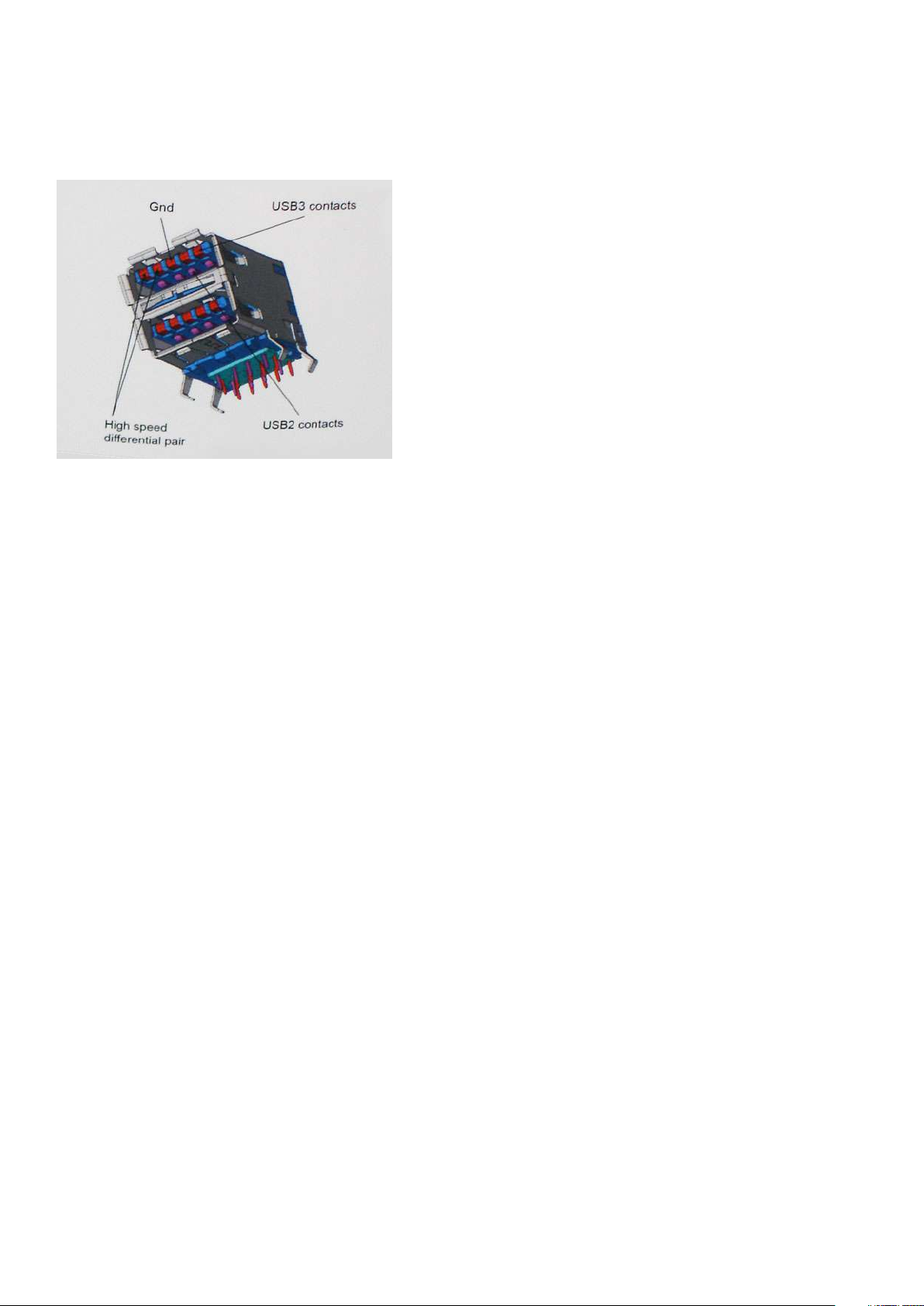
• USB 2.0 previously had four wires (power, ground, and a pair for differential data); USB 3.2 Gen 1 adds four more for two pairs of
differential signals (receive and transmit) for a combined total of eight connections in the connectors and cabling.
• USB 3.2 Gen 1 utilizes the bi-directional data interface, rather than USB 2.0's half-duplex arrangement. This gives a 10-fold increase in
theoretical bandwidth.
With today's ever increasing demands that are placed on data transfers with high-definition video content, terabyte storage devices, high
megapixel count digital cameras etc., USB 2.0 may not be fast enough. Furthermore, no USB 2.0 connection could ever come close to the
480Mbps theoretical maximum throughput, making data transfer at around 320 Mbps (40 MB/s) — the actual real-world maximum.
Similarly, USB 3.2 Gen 1 connections will never achieve 4.8Gbps. We will likely see a real-world maximum rate of 400 MB/s with
overheads. At this speed, USB 3.2 Gen 1 is a 10x improvement over USB 2.0.
Applications
USB 3.2 Gen 1 opens up the laneways and provides more headroom for devices to deliver a better overall experience. Where USB video
was barely tolerable previously (both from a maximum resolution, latency, and video compression perspective), it's easy to imagine that
with 5-10 times the bandwidth available, USB video solutions should work that much better. Single-link DVI requires almost 2Gbps
throughput. Where 480Mbps was limiting, 5Gbps is more than promising. With its promised 4.8Gbps speed, the standard will find its way
into some products that previously weren't USB territory, like external RAID storage systems.
Listed below are some of the available Super-Speed USB 3.2 Gen 1 products:
• External Desktop USB 3.2 Gen 1 Hard Drives
• Portable USB 3.2 Gen 1 Hard Drives
• USB 3.2 Gen 1 Drive Docks & Adapters
• USB 3.2 Gen 1 Flash Drives & Readers
• USB 3.2 Gen 1 Solid-state Drives
• USB 3.2 Gen 1 RAIDs
• Optical Media Drives
• Multimedia Devices
• Networking
• USB 3.2 Gen 1 Adapter Cards & Hubs
Compatibility
The good news is that USB 3.2 Gen 1 has been carefully planned from the start to peacefully co-exist with USB 2.0. First of all, while USB
3.2 Gen 1 specifies new physical connections and thus new cables to take advantage of the higher speed capability of the new protocol,
the connector itself remains the same rectangular shape with the four USB 2.0 contacts in the exact same location as before. Five new
connections to carry receive and transmitted data independently are present on USB 3.2 Gen 1 cables and only come into contact when
connected to a proper Super-Speed USB connection.
USB Type-C
USB Type-C is a new, tiny physical connector. The connector itself can support various exciting new USB standards like USB 3.1 and USB
power delivery (USB PD).
Technology and components
11
Page 12
Alternate Mode
USB Type-C is a new connector standard that is very small. It is about a third the size of an old USB Type-A plug. This is a single
connector standard that every device should be able to use. USB Type-C ports can support a variety of different protocols using
“alternate modes,” which allows you to have adapters that can output HDMI, VGA, DisplayPort, or other types of connections from that
single USB port
USB Power Delivery
The USB PD specification is also closely intertwined with USB Type-C. Currently, smartphones, tablets, and other mobile devices often
use a USB connection to charge. A USB 2.0 connection provides up to 2.5 watts of power — that'll charge your phone, but that's about
it. A laptop might require up to 60 watts, for example. The USB Power Delivery specification ups this power delivery to 100 watts. It's bidirectional, so a device can either send or receive power. And this power can be transferred at the same time the device is transmitting
data across the connection.
This could spell the end of all those proprietary laptop charging cables, with everything charging via a standard USB connection. You could
charge your laptop from one of those portable battery packs you charge your smartphones and other portable devices from today. You
could plug your laptop into an external display connected to a power cable, and that external display would charge your laptop as you used
it as an external display — all via the one little USB Type-C connection. To use this, the device and the cable have to support USB Power
Delivery. Just having a USB Type-C connection doesn't necessarily mean they do.
USB Type-C and USB 3.1
USB 3.1 is a new USB standard. USB 3's theoretical bandwidth is 5 Gbps, while USB 3.1's is 10 Gbps. That's double the bandwidth, as fast
as a first-generation Thunderbolt connector. USB Type-C isn't the same thing as USB 3.1. USB Type-C is just a connector shape, and the
underlying technology could just be USB 2 or USB 3.0. In fact, Nokia's N1 Android tablet uses a USB Type-C connector, but underneath
it's all USB 2.0 — not even USB 3.0. However, these technologies are closely related.
Thunderbolt over USB Type-C
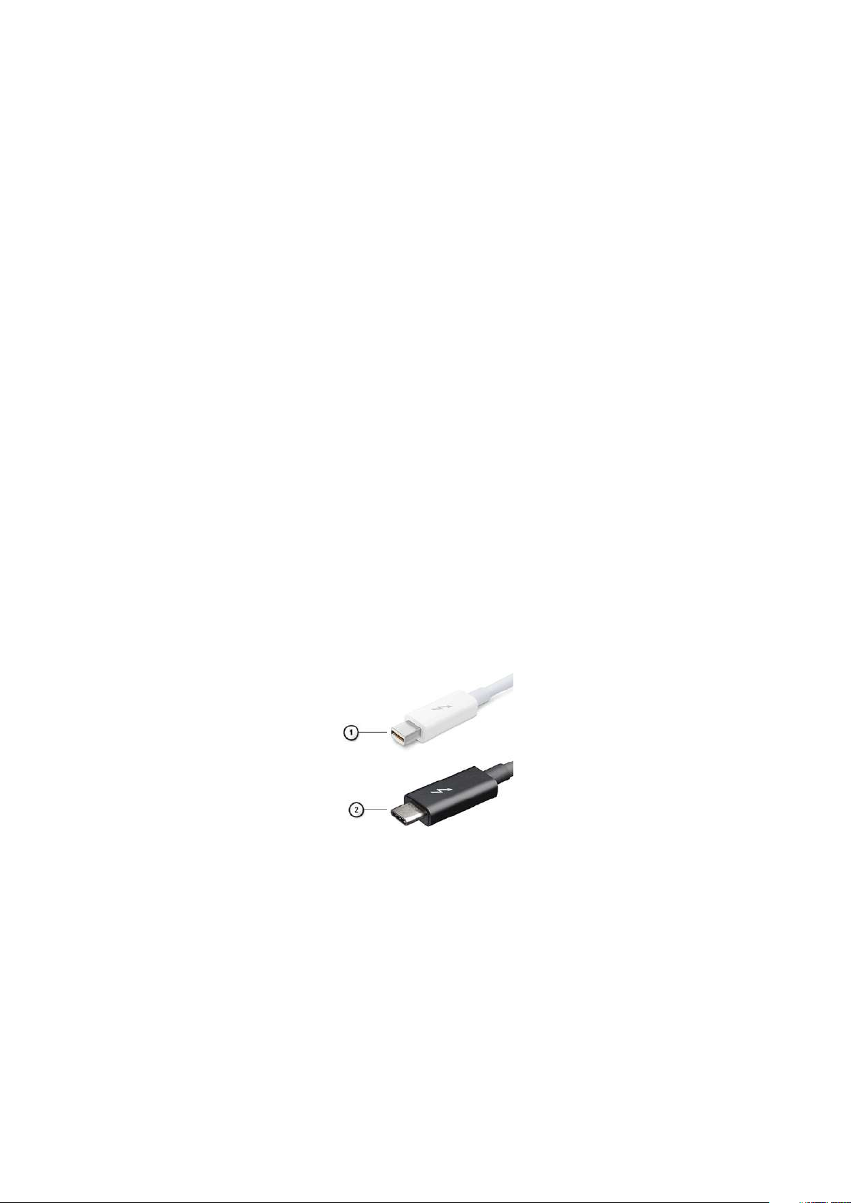
Thunderbolt is a hardware interface that combines data, video, audio, and power in a single connection. Thunderbolt combines PCI
Express (PCIe) and DisplayPort (DP) into one serial signal, and additionally provides DC power, all in one cable. Thunderbolt 1 and
Thunderbolt 2 use the same connector as miniDP (DisplayPort) to connect to peripherals, while Thunderbolt 3 uses a USB Type-C
connector.
Figure 1. Thunderbolt 1 and Thunderbolt 3
1. Thunderbolt 1 and Thunderbolt 2 (using a miniDP connector)
2. Thunderbolt 3 (using a USB Type-C connector)
Thunderbolt 3 over USB Type-C
Thunderbolt 3 brings Thunderbolt to USB Type-C at speeds up to 40 Gbps, creating one compact port that does it all - delivering the
fastest, most versatile connection to any dock, display or data device like an external hard drive. Thunderbolt 3 uses a USB Type-C
connector/port to connect to supported peripherals.
1. Thunderbolt 3 uses USB Type-C connector and cables - It is compact and reversible
2. Thunderbolt 3 supports speed up to 40 Gbps
12
Technology and components
Page 13
3. DisplayPort 1.4 – compatible with existing DisplayPort monitors, devices and cables
4. USB Power Delivery - Up to 130W on supported computers
Key Features of Thunderbolt 3 over USB Type-C
1. Thunderbolt, USB, DisplayPort and power on USB Type-C on a single cable (features vary between different products)
2. USB Type-C connector and cables which are compact and reversible
3. Supports Thunderbolt Networking (*varies between different products)
4. Supports up to 4K displays
5. Up to 40 Gbps
NOTE: Data transfer speed may vary between different devices.
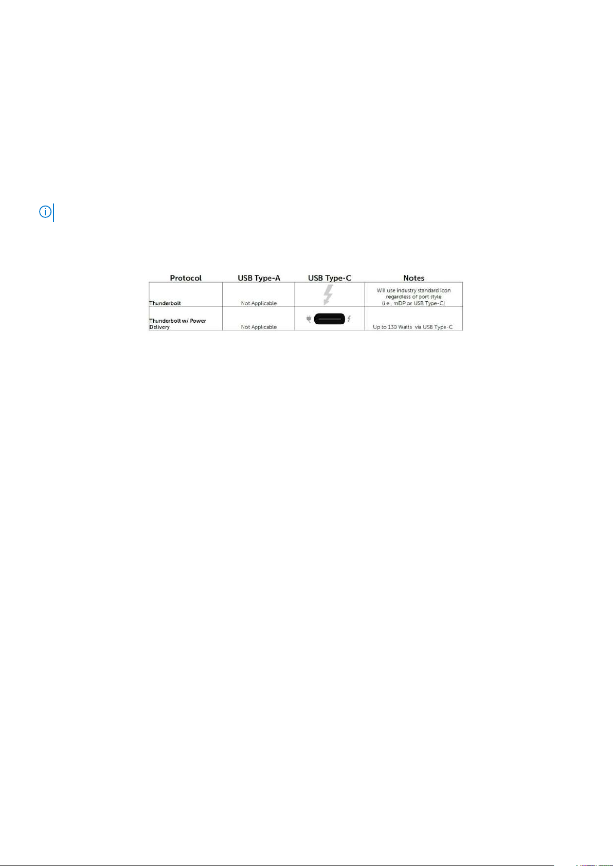
Thunderbolt Icons
Figure 2. Thunderbolt Iconography Variations
HDMI 1.4
This topic explains the HDMI 1.4 and its features along with the advantages.
HDMI (High-Definition Multimedia Interface) is an industry-supported, uncompressed, all-digital audio/video interface. HDMI provides an
interface between any compatible digital audio/video source, such as a DVD player, or A/V receiver and a compatible digital audio and/or
video monitor, such as a digital TV (DTV). The primary advantage is cable reduction and content protection provisions. HDMI supports
standard, enhanced, or high-definition video, plus multichannel digital audio on a single cable.
HDMI 1.4 Features
• HDMI Ethernet Channel - Adds high-speed networking to an HDMI link, allowing users to take full advantage of their IP-enabled
devices without a separate Ethernet cable.
• Audio Return Channel - Allows an HDMI-connected TV with a built-in tuner to send audio data "upstream" to a surround audio
system, eliminating the need for a separate audio cable.
• 3D - Defines input/output protocols for major 3D video formats, paving the way for true 3D gaming and 3D home theater applications.
• Content Type - Real-time signaling of content types between display and source devices, enabling a TV to optimize picture settings
based on content type.
• Additional Color Spaces - Adds support for additional color models used in digital photography and computer graphics.
• 4K Support - Enables video resolutions far beyond 1080p, supporting next-generation displays that will rival the Digital Cinema
systems used in many commercial movie theaters.
• HDMI Micro Connector - A new, smaller connector for phones and other portable devices, supporting video resolutions up to 1080p.
• Automotive Connection System - New cables and connectors for automotive video systems, designed to meet the unique
demands of the motoring environment while delivering true HD quality.
Advantages of HDMI
• Quality HDMI transfers uncompressed digital audio and video for the highest, crispest image quality.
• Low-cost HDMI provides the quality and functionality of a digital interface while also supporting uncompressed video formats in a
simple, cost-effective manner.
• Audio HDMI supports multiple audio formats from standard stereo to multichannel surround sound.
• HDMI combines video and multichannel audio into a single cable, eliminating the cost, complexity, and confusion of multiple cables
currently used in A/V systems.
Technology and components
13
Page 14

• HDMI supports communication between the video source (such as a DVD player) and the DTV, enabling new functionality.
Power button LED behavior
On certain Dell Latitude systems, the power button LED is used to provide an indication of the system status, and as a result the power
button illuminates when pressed. The systems with the optional power button/fingerprint reader will have no LED under the power button
and hence will apply the available LED's in the system to provide an indication of the system status.
Power button LED behavior without Fingerprint reader
• System is ON (S0) = LED illuminates solid white.
• System in Sleep/Standby (S3, SOix) = LED is off
• System is Off/Hibernating (S4/S5) = LED is off
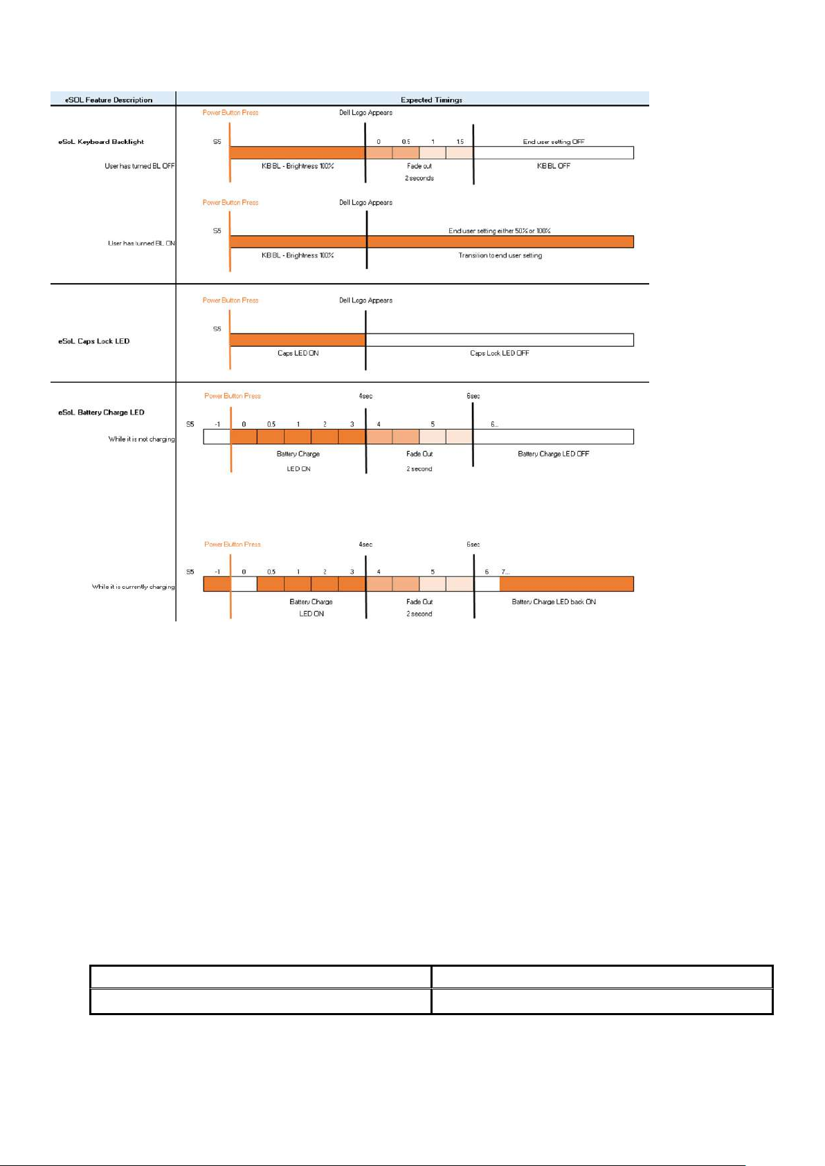
Power On and LED behavior with Fingerprint reader
• Pressing the power button for a duration between 50 msec to 2 sec turns on the device.
• Power button does not register additional presses until the SOL (Sign-Of-Life) has been provided to the user.
• System LED's illuminates upon pressing the power button.
• All the available LED's (Keyboard backlit/ Keyboard caps lock LED/ Battery Charge LED) illuminates and displays specified behavior.
• The auditory tone is Off by default. It can be enabled in the BIOS setup.
• Safeguards do not time out if the device gets hung during the logon process.
• Dell logo: Turns on within 2 secs after pressing the power button.
• Full boot: Within 22 secs after pressing the power button.
• Below is the example timelines:
14
Technology and components
Page 15
Power button with fingerprint reader will have no LED and will leverage the available LED's in the system to provide indication of the
system status
• Power Adapter LED:
○ The LED on Power adapter connector illuminates white when power is supplied from electrical outlet.
• Battery Indicator LED:
○ If the computer is connected to an electrical outlet, the battery light operates as follows:
1. Solid white -the battery is charging. When the charge is complete the LED turns off.
○ If the computer is running on a battery, the battery light operates as follows:
1. Off -the battery is adequately charged (or the computer is turned off).
2. Solid amber -the battery charge is critically low. A low battery state is approximately 30 minutes or less of battery life
remaining.
• Camera LED
○ White LED activates when camera is on.
• Mic Mute LED:
○ When activated (muted), the mic mute LED on the F4 Key should illuminate WHITE.
• RJ45 LEDs:
○
Table 2. LED on either side of RJ45 port
Link speed indicator (LHS) Activity indicator (RHS)
Green Amber
Technology and components 15
Page 16
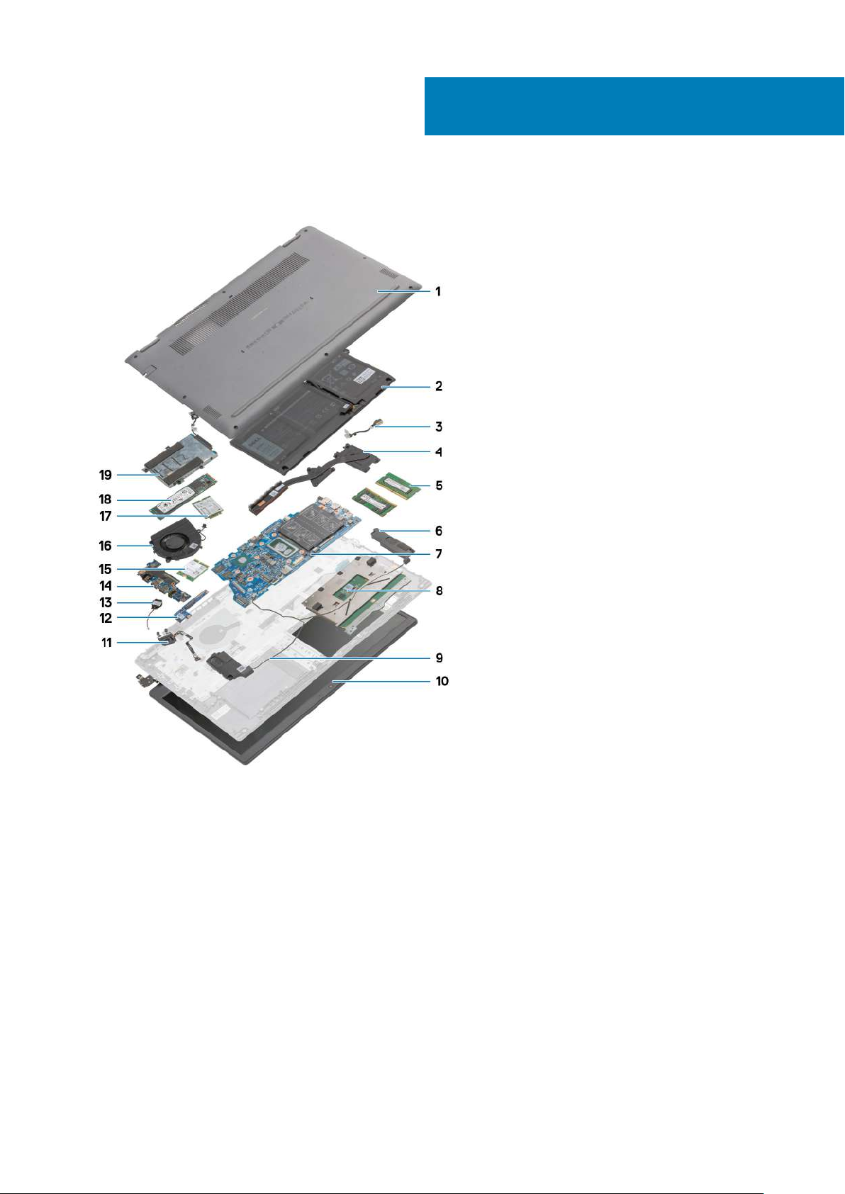
3
Major components of your system
1. Base Cover
2. Battery
3. DC-in Port
4. Heatsink
5. Memory Modules
6. Speakers
7. System Board
8. Touchpad
9. Palmrest Assembly
10. Display Assembly
11. Power Button Module
12. Daughterboard Module
13. Coin-cell Battery
14. IO Board
15. WLAN Card
16. Fan Assembly
17. WWAN Card
16 Major components of your system
Page 17

18. Solid-state Drive
19. Hard Drive Assembly
NOTE: Dell provides a list of components and their part numbers for the original system configuration purchased. These
parts are available according to warranty coverages purchased by the customer. Contact your Dell sales representative
for purchase options.
Major components of your system 17
Page 18
Disassembly and reassembly
MicroSD card
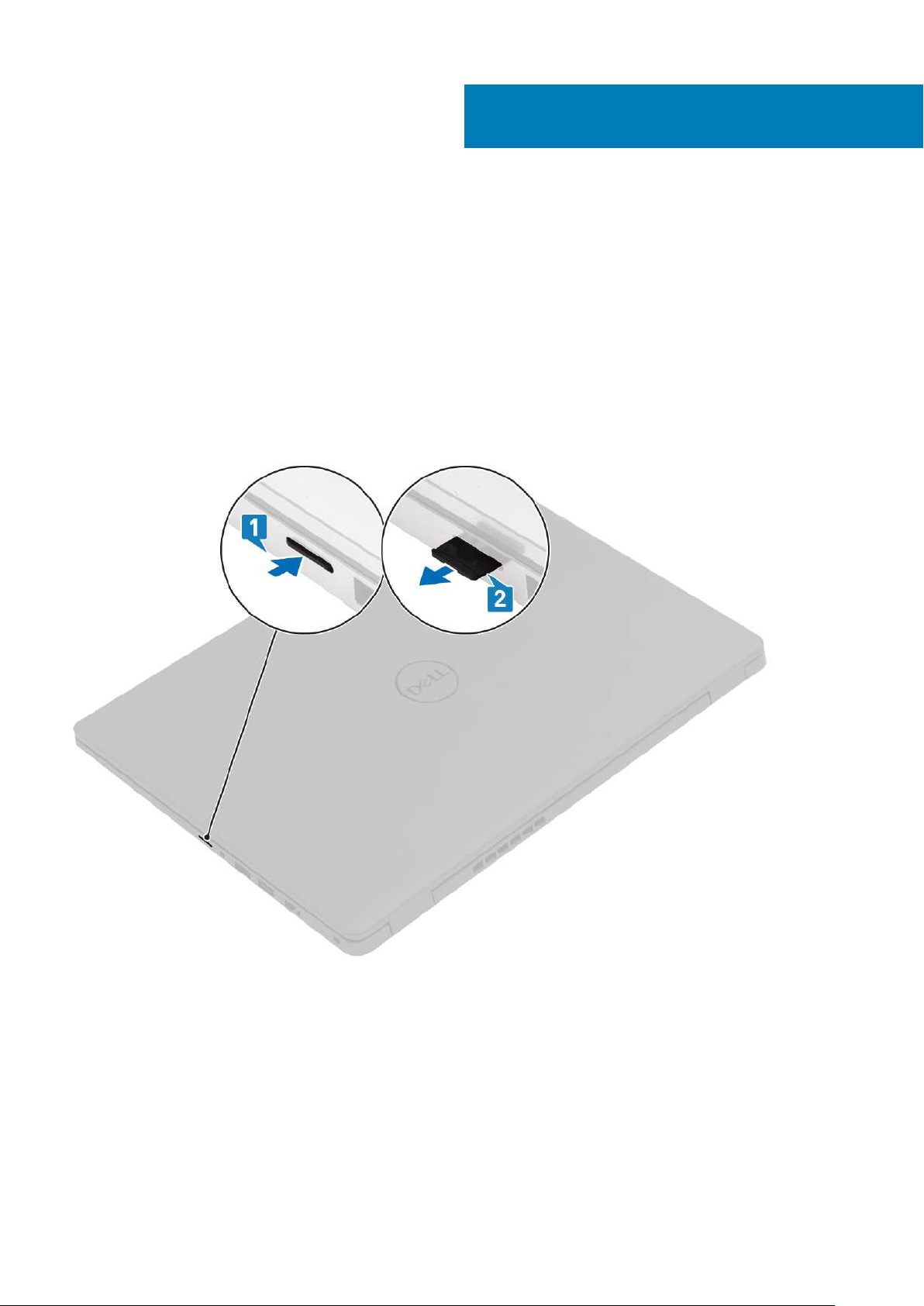
Removing the microSD card
Prerequisites
1. Follow the procedure in Before working inside your computer.
About this task
4
Steps
1. Push the microSD card to release it from the computer.
2. Slide the microSD card out of the computer.
18 Disassembly and reassembly
Page 19
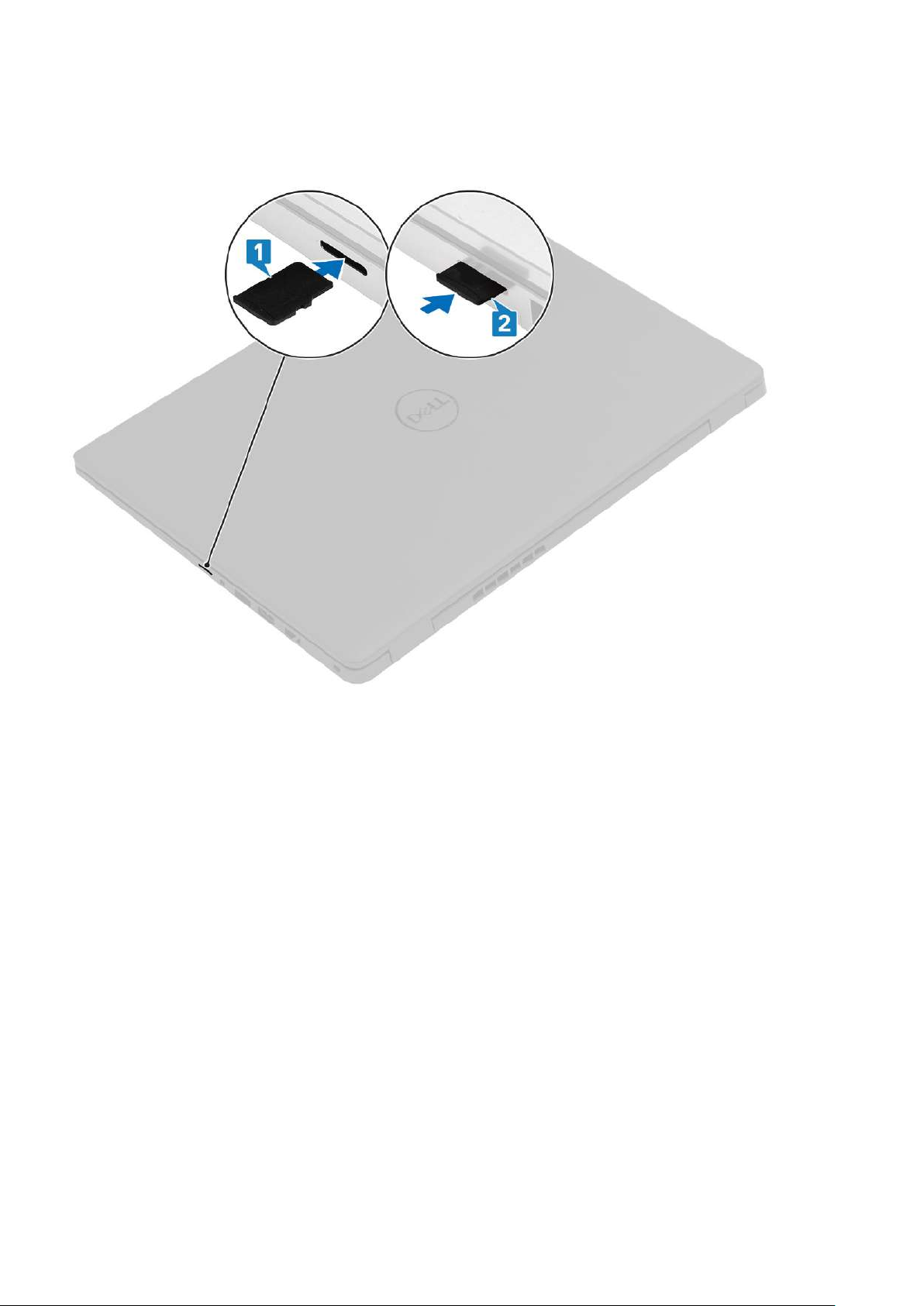
Installing the microSD card
About this task
Steps
1. Align the microSD card to its slot on the computer.
2. Slide the microSD card into the slot until it clicks into place.
Next steps
Follow the procedures in After working inside your computer.
SIM card
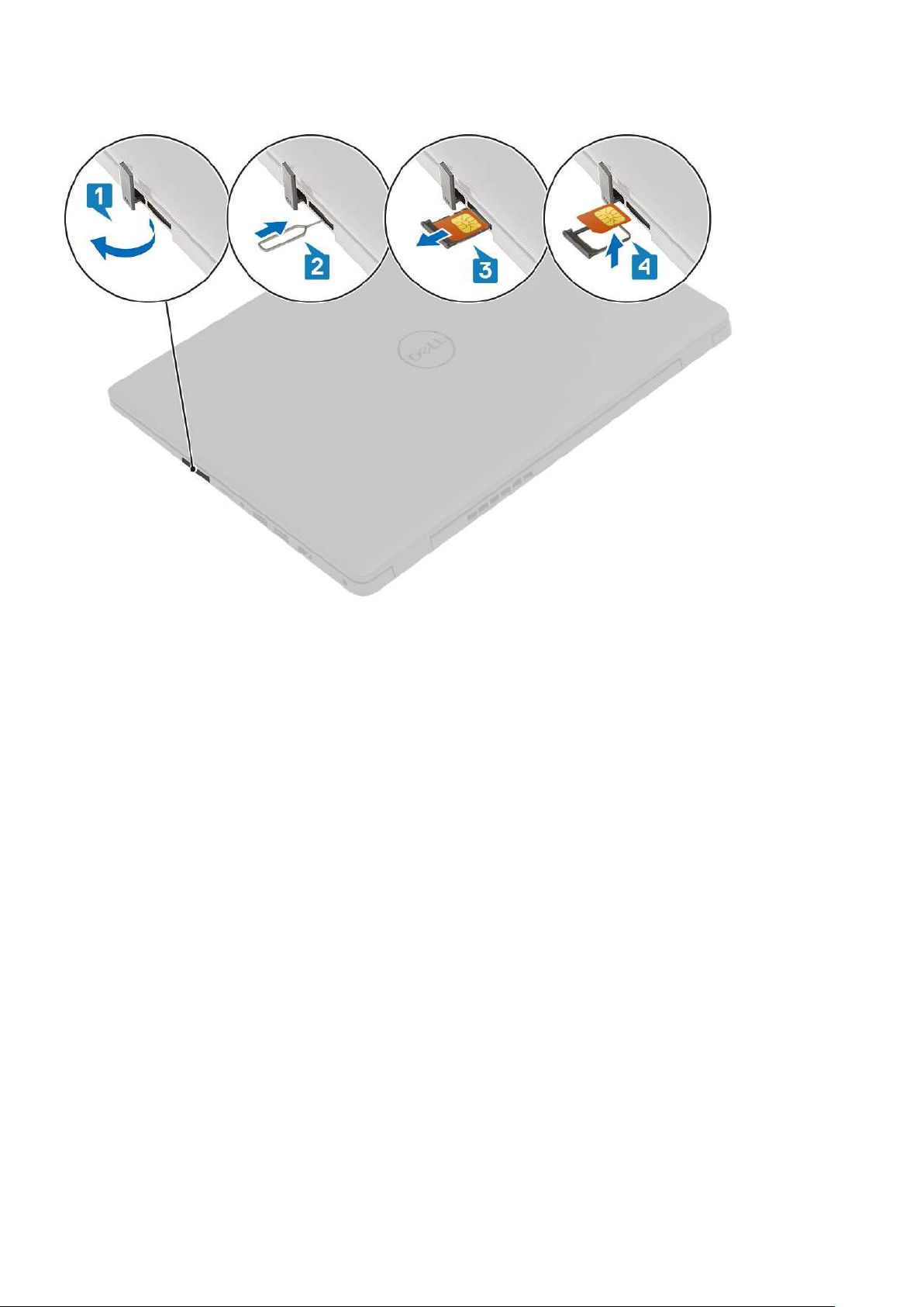
Removing the SIM card
Prerequisites
1. Follow the procedure in Before working inside your computer
Disassembly and reassembly
19
Page 20
About this task
Steps
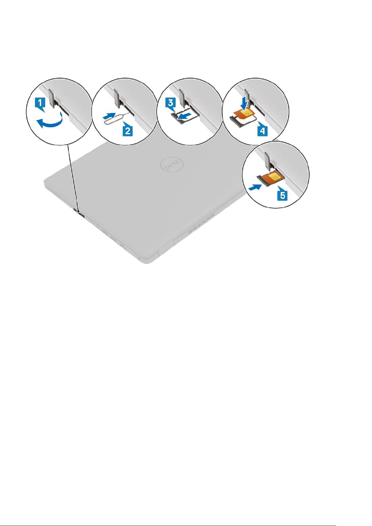
1. Open the latch that covers the SIM card slot to release it from the system.
2. Insert a SIM card remover tool in the slot and push it to eject the SIM card tray.
3. Pull the SIM card try and remove the SIM card from the SIM card tray.
20
Disassembly and reassembly
Page 21
Installing the SIM card
About this task
Steps
1. Open the latch that covers the SIM card slot to release it from the system.
2. Insert the SIM card removal tool in the slot and push it to eject the SIM card tray [2].
3. Pull the SIM card holder out of the slot.
4. Place the SIM card into the SIM card holder.
5. Slide the SIM card tray into the slot until it clicks into place.
Next steps
Follow the procedures in After working inside your computer.
Base cover
Removing the base cover
Prerequisites
1. Follow the procedure in before working inside your computer.
2. Remove the SD Card.
Disassembly and reassembly
21
Page 22
About this task
22 Disassembly and reassembly
Page 23

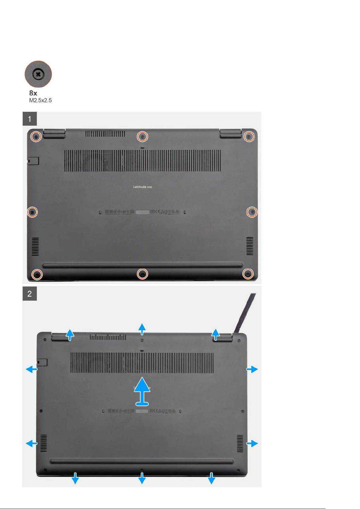
Steps
1. Loosen the eight (M2.5x2.5) screws that secure the bottom base to the computer.
2. Using a plastic scribe, pry the base cover from the top-right corner and lift the base cover away from the computer.
Installing the base cover
Prerequisites
If you are replacing a component, remove the existing component before performing the installation procedure.
Disassembly and reassembly 23
Page 24
About this task
The figure indicates the location of the base cover and provides a visual representation of the installation procedure.
24 Disassembly and reassembly
Page 25

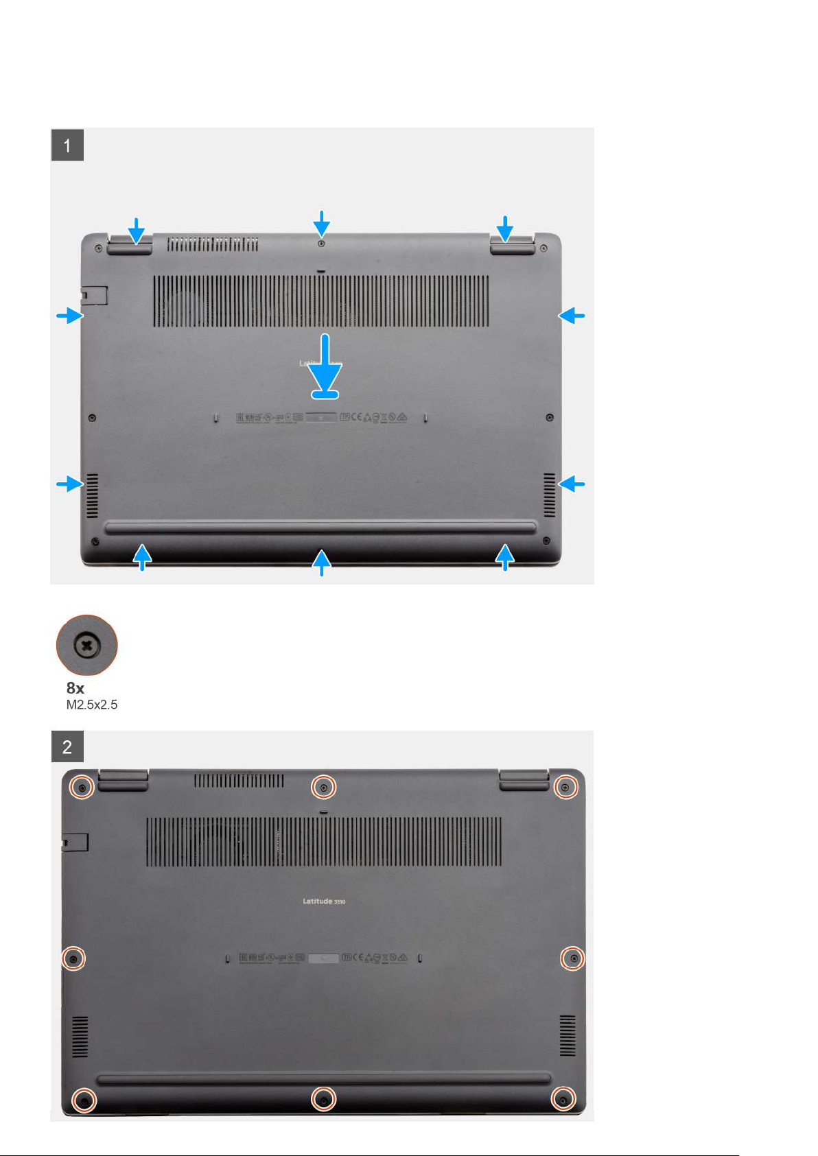
Steps
1. Align and place the base cover on the computer, press the edges and sides of the base cover until it snaps into place.
2. Tighten the eight (M2.5x2.5) screws to secure the base cover to the computer.
Next steps
1. Replace the SD Card.
2. Follow the procedure in after working inside your computer.
Battery
Lithium-ion battery precautions
CAUTION:
• Exercise caution when handling Lithium-ion batteries.
• Discharge the battery as much as possible before removing it from the system. This can be done by disconnecting
the AC adapter from the system to allow the battery to drain.
• Do not crush, drop, mutilate, or penetrate the battery with foreign objects.
• Do not expose the battery to high temperatures, or disassemble battery packs and cells.
• Do not apply pressure to the surface of the battery.
• Do not bend the battery.
• Do not use tools of any kind to pry on or against the battery.
• Ensure any screws during the servicing of this product are not lost or misplaced, to prevent accidental puncture or
damage to the battery and other system components.
• If the battery gets stuck inside your computer as a result of swelling, do not try to release it as puncturing, bending,
or crushing a lithium-ion battery can be dangerous. In such an instance, contact Dell technical support for
assistance. See www.dell.com/contactdell.
• Always purchase genuine batteries from www.dell.com or authorized Dell partners and resellers.
Removing the battery
Prerequisites
1. Follow the procedure in before working inside your computer.
2. Remove the microSD card.
3. Remove the base cover.
Disassembly and reassembly
25
Page 26

Steps
1. Disconnect the battery cable from the connector on the system board.
2. Remove the four (M2x3) screws that secures the battery to the palm rest assembly.
3. Lift and move the battery away from the computer.
Installing the battery
Prerequisites
If you are replacing a component, remove the existing component before performing the installation procedure.
About this task
The figure indicates the location of the battery and provides a visual representation of the installation procedure.
26
Disassembly and reassembly
Page 27

Steps
1. Align the tabs on the battery with the slots on the palm rest assembly.
2. Place the battery in the battery bay.
3. Tighten the four (M2x3) screws to secure the battery to the palm rest assembly.
4. Connect the battery cable to the connector on the system board.
Next steps
1. Replace the base cover.
2. Replace the SD Card.
3. Follow the procedure in after working inside your computer
Memory modules
Removing the memory module
Prerequisites
1. Follow the procedure in before working inside your computer.
2. Remove the SD Card.
3. Remove the base cover.
4. Disconnect the battery.
About this task
The following images indicate the location of the memory module and provide a visual representation of the removal procedure.
Disassembly and reassembly
27
Page 28

Steps
1. Peel the adhesive cover above the memory module.
2. Pry the clips securing the memory module until the memory module pops-up.
3. Remove the memory module from the memory slot.
Installing the memory modules
Prerequisites
If you are replacing a component, remove the existing component before performing the installation procedure.
About this task
The figure indicates the location of the memory module and provides a visual representation of the installation procedure.
28
Disassembly and reassembly
Page 29

Steps
1. Peel back the adhesive cover from over the memory slot.
2. Align the notch on the memory module with the tab on the memory module slot.
3. Slide the memory module firmly into the slot at an angle.
4. Press the memory module down until it clicks into place.
NOTE: If you do not hear the click, remove the memory module and reinstall it.
Next steps
1. Install the battery.
2. Install the base cover.
3. Install the SD Card.
4. Follow the procedure in After working inside your computer.
Disassembly and reassembly
29
Page 30

WLAN card
Removing the WLAN card
Prerequisites
1. Follow the procedure in Before working inside your computer.
2. Remove the SD card
3. Remove the base cover.
4. Remove the battery.
About this task
The figure indicates the location of the WLAN card and provides a visual representation of the removal procedure.
Steps
1. Remove the single (M2x3) screw that secures the WLAN bracket to the computer.
2. Remove the WLAN bracket.
3. Disconnect the WLAN antenna cables from the WLAN module.
4. Slide and remove the WLAN card from the WLAN card slot.
30
Disassembly and reassembly
Page 31

Installing the WLAN card
Prerequisites
If you are replacing a component, remove the existing component before performing the installation procedure.
About this task
The figure indicates the location of the WLAN card and provides a visual representation of the installation procedure.
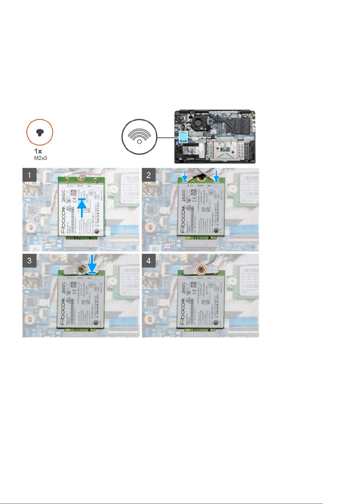
Steps
1. Align the notch on the WLAN card with the tab on the WLAN-card slot and insert the WLAN card at an angle into the WLAN-card
slot.
2. Connect the WLAN antenna cables to the WLAN card.
3. Align and place the WLAN-card bracket to secure the WLAN card to the system board.
4. Replace the single (M2x3) screw to secure the WLAN card to the system board.
Next steps
1. Install the battery cable.
2. Install the base cover.
3. Install the SD Card
4. Follow the procedure in After working inside your computer.
Disassembly and reassembly
31
Page 32

WWAN card
Removing the WWAN card
Prerequisites
1. Follow the procedure in Before working inside your computer.
2. Remove the SD card
3. Remove the base cover.
4. Remove the battery.
About this task
The figure indicates the location of the WLAN card and provides a visual representation of the removal procedure.
Steps
1. Remove the single (M2x3) screw that secures the WWLAN bracket to the computer.
2. Remove the WWAN bracket.
3. Disconnect the WWAN antenna cables from the WWAN module.
4. Slide and remove the WWAN card from the WWAN card slot.
32
Disassembly and reassembly
Page 33
Installing the WWAN card
Prerequisites
If you are replacing a component, remove the existing component before performing the installation procedure.
About this task
The figure indicates the location of the WWAN card and provides a visual representation of the installation procedure.
Steps
1. Align the notch on the WWAN card with the tab on the WWAN-card slot and insert the WWAN card at an angle into the WWAN-card
slot.
2. Connect the WWAN antenna cables to the WWAN card.
3. Align and place the WWAN-card bracket to secure the WWAN card to the system board.
4. Replace the single (M2x3) screw to secure the WWAN card to the system board.
Next steps
1. Install the battery cable.
2. Install the base cover.
3. Install the SD card
4. Follow the procedure in After working inside your computer.
Disassembly and reassembly
33
Page 34
Coin-cell battery
Removing the coin-cell battery
Prerequisites
1. Follow the procedure in Before working inside your computer.
2. Remove the SD card.
3. Remove the base cover.
4. Remove the battery.
About this task
The figure indicates the location of the coin-cell battery and provides a visual representation of the removal procedure.
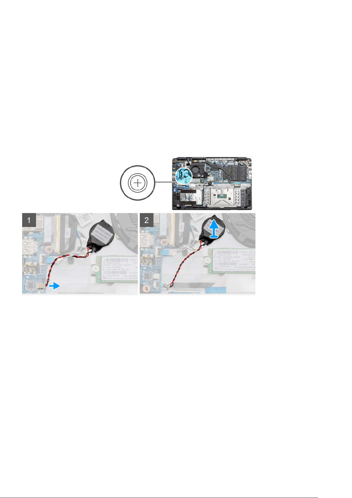
Steps
1. Disconnect the coin-cell battery cable from the system board.
2. Peel the coin-cell battery off the palmrest assembly as the coin-cell is affixed to the board with an adhesive.
Installing the coin-cell battery
Prerequisites
If you are replacing a component, remove the existing component before performing the installation procedure.
About this task
The figure indicates the location of the coin-cell and provides a visual representation of the installation procedure.
34
Disassembly and reassembly
Page 35
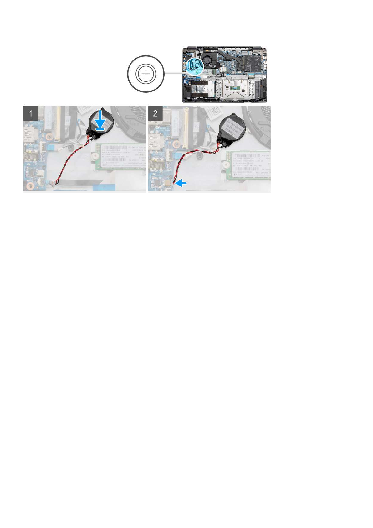
Steps
1. Re-adhere the coin-cell battery to the slot on the palmrest assembly.
2. Connect the coin-cell battery cable to the system board.
Next steps
1. Install the battery.
2. Install the base cover.
3. Install the SD card
4. Follow the procedure in After working inside your computer.
DC-in port
Removing the DC-in
Prerequisites
1. Follow the procedure in Before working inside your computer.
2. Remove the SD card.
3. Remove the base cover.
4. Remove the battery.
About this task
The figure indicates the location of the DC-in and provides a visual representation of the removal procedure.
Disassembly and reassembly
35
Page 36
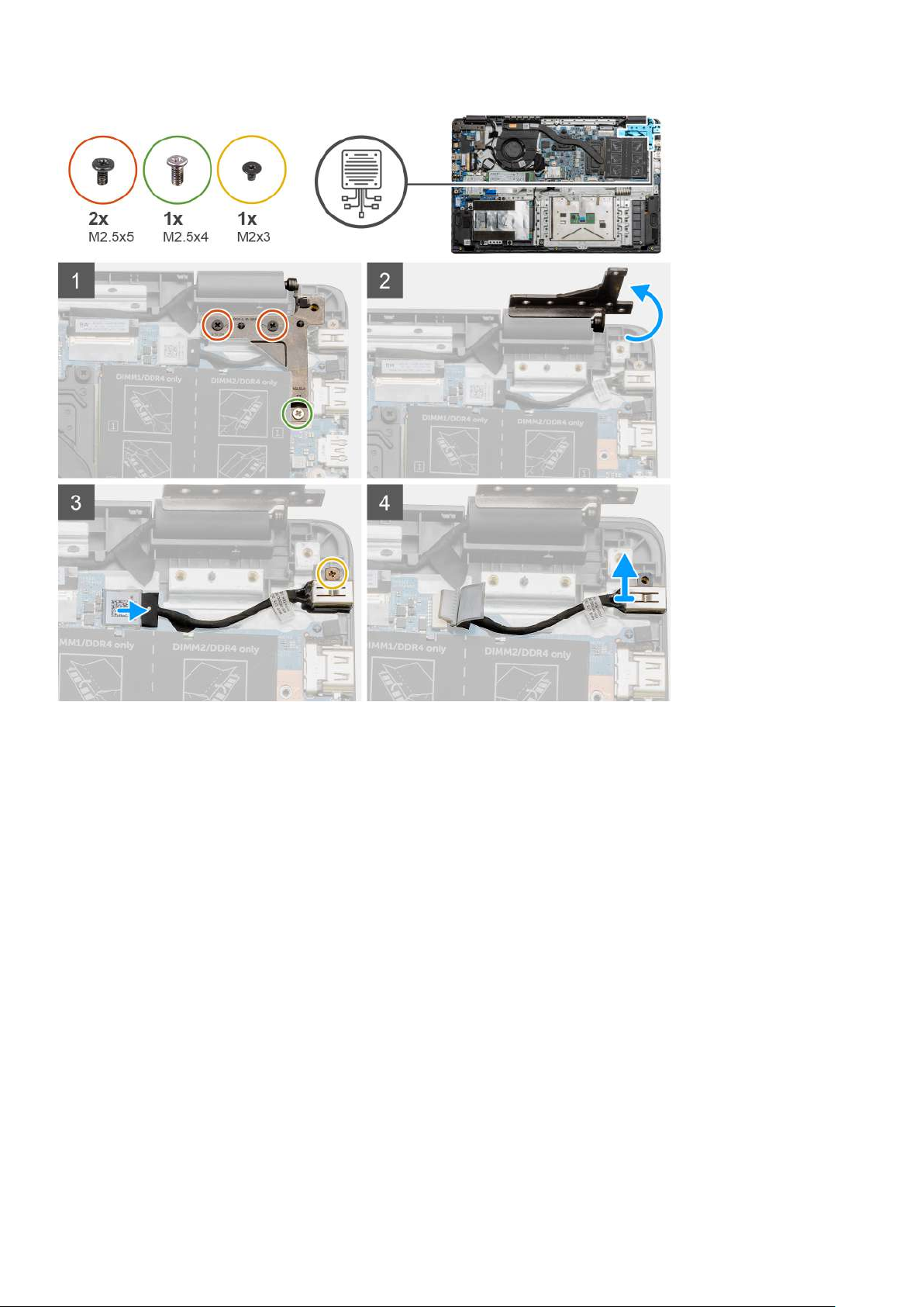
Steps
1. Locate the DC-in port on your computer, remove the two (M2.5x5) and one (M2.5x4) screws from the hinge covering it.
2. Lift the hinge and fold it away from the chassis.
3. Disconnect the DC-in cable from the computer and remove the single (M2x3) screw.
4. Remove the DC-in port from the computer.
Installing the DC-in
Prerequisites
If you are replacing a component, remove the existing component before performing the installation procedure.
About this task
The figure indicates the location of the DC-in port and provides a visual representation of the installation procedure.
36
Disassembly and reassembly
Page 37
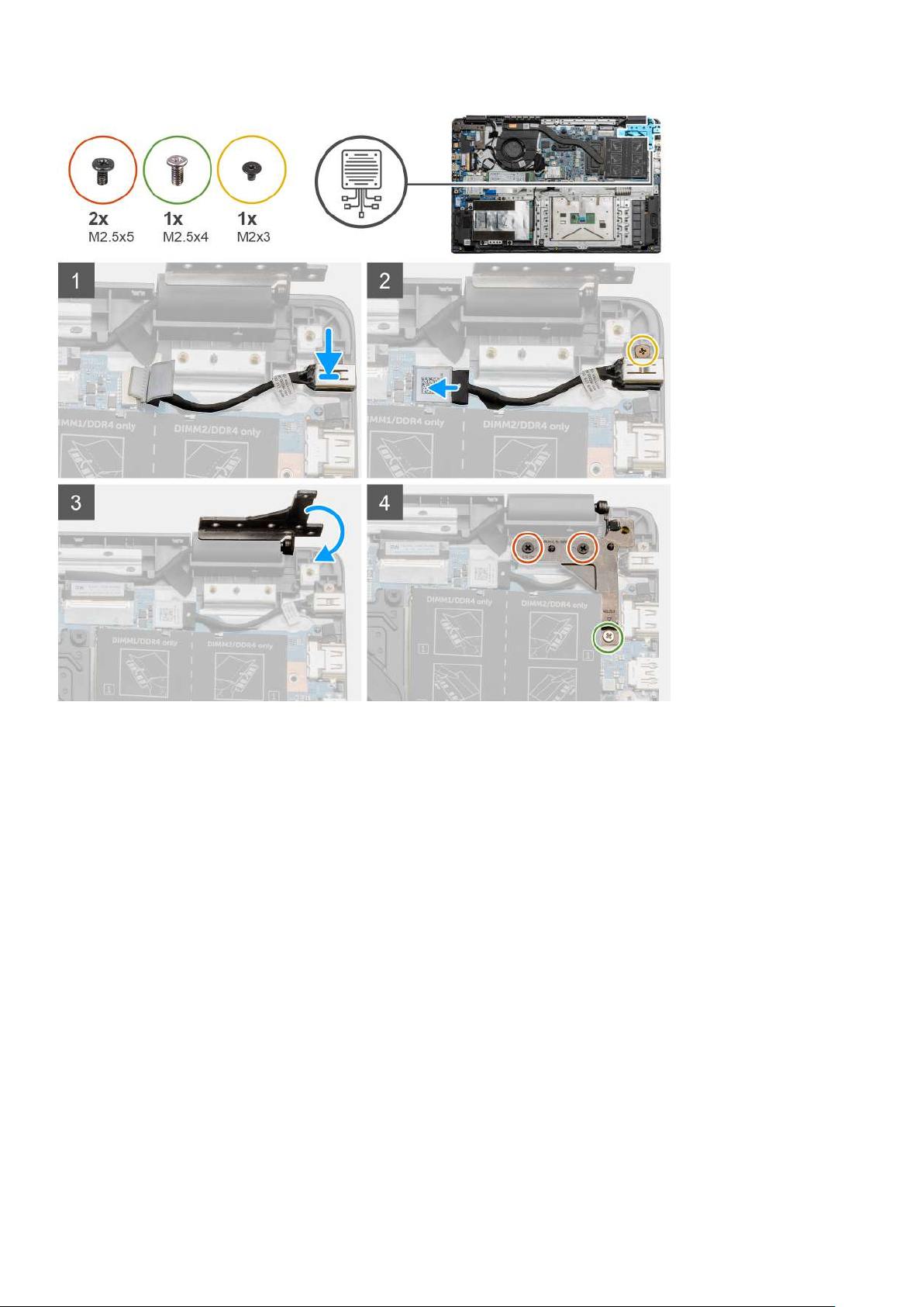
Steps
1. Place the DC-in module into the provided slot.
2. Install the (M2x3) screw and connect the DC-in cable to the system board.
3. Fold and align the hinge to the screw holders on the palmrest.
4. Install the two (M2.5x5) and one (M2.5x4) screws to secure the hinge.
Next steps
1. Install the battery.
2. Install the base cover.
3. Install the SD card.
4. Follow the procedure in After working inside your computer.
Solid state drive
Solid state drive bracket
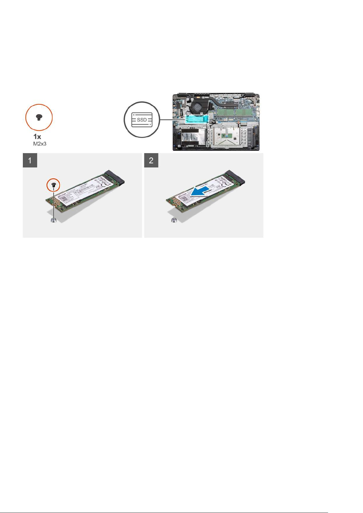
Removing the M.2 2280 solid-state drive
Prerequisites
1. Follow the procedure in before working inside your computer.
Disassembly and reassembly
37
Page 38
2. Remove the SD Card.
3. Remove the base cover.
4. Disconnect the battery.
About this task
The figure indicates the location of the M.2 2280 solid-state drive and provides a visual representation of the removal procedure.
Steps
1. Remove the single (M2x3) screw that secures the solid-state module to the palmrest assembly.
2. Slide the solid-state module out from the M.2 slot.
Installing M.2 2280 solid-state drive
Prerequisites
If you are replacing a component, remove the existing component before performing the installation procedure.
About this task
The figure indicates the location of the M.2 2280 solid-state drive and provides a visual representation of the installation procedure.
38
Disassembly and reassembly
Page 39

Steps
1. Align and slide the solid-state drive into the slot.
2. Replace the single (M2x3) screw to secure the solid-state drive module to the system.
Next steps
1. Install the battery cable.
2. Install the base cover.
3. Install the SD card.
4. Follow the procedure in After working inside your computer.
Removing the M.2 2230 solid-state drive
Prerequisites
1. Follow the procedure in before working inside your computer.
2. Remove the SD Card.
3. Remove the base cover.
4. Disconnect the battery.
About this task
The figure indicates the location of the M.2 2230 solid-state drive and provides a visual representation of the removal procedure.
Disassembly and reassembly
39
Page 40
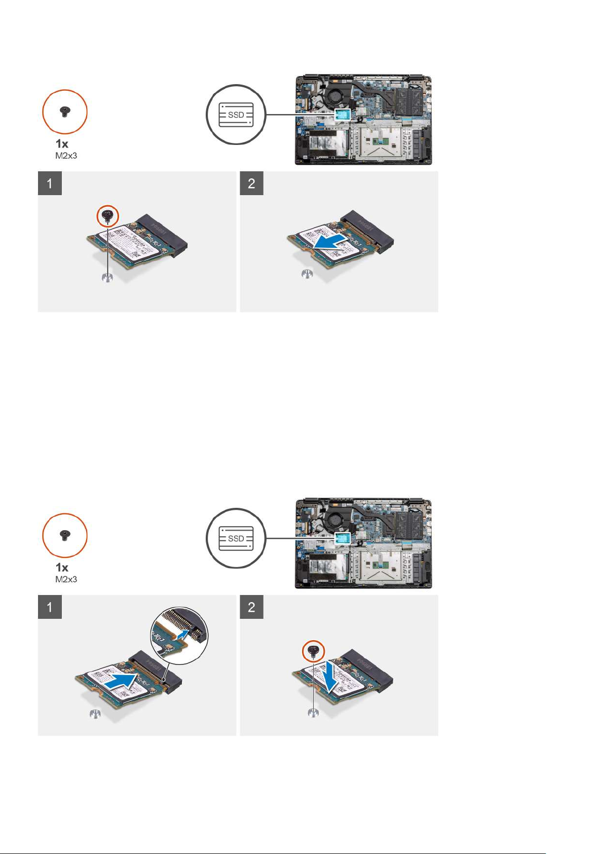
Steps
1. Remove the single (M2x3) screw that secures the solid-state module to the palmrest assembly.
2. Slide the solid-state module out from the M.2 slot.
Installing M.2 2230 solid-state drive
Prerequisites
If you are replacing a component, remove the existing component before performing the installation procedure.
About this task
The figure indicates the location of the M.2 2230 solid-state drive and provides a visual representation of the installation procedure.
40
Disassembly and reassembly
Page 41

Steps
1. Align and slide the solid-state drive into the slot.
2. Replace the single (M2x3) screw to secure the solid-state drive module to the palmrest and keyboard assembly.
Next steps
1. Install the battery cable.
2. Install the base cover.
3. Install the SD card.
4. Follow the procedure in After working inside your computer.
Installing M.2 solid-state drive bracket
Prerequisites
If you are replacing a component, remove the existing component before performing the installation procedure.
About this task
The figure indicates the location of the M.2 solid-state drive bracket and provides a visual representation of the installation procedure.
Steps
1. Slide the bracket out of the metal holder.
2. Rotate the bracket so that it faces the opposite side from its original mounting position.
3. Slide the bracket into the metal holder on the opposite end.
Next steps
1. Install the battery cable.
2. Install the base cover.
3. Follow the procedure in After working inside your computer.
Disassembly and reassembly
41
Page 42

Hard Drive
Removing the Hard Drive
Prerequisites
1. Follow the procedure in before working inside your computer.
2. Remove the SD Card.
3. Remove the base cover.
4. Disconnect the battery.
About this task
The following images indicate the location of the hard drive and provide a visual representation of the removal procedure.
Steps
1. Remove the four M3x3 screws and disconnect the hard drive cable from the connector on the system board.
2. Remove the hard drive from the computer.
Installing the Hard Drive
Prerequisites
If you are replacing a component, remove the existing component before performing the installation procedure.
About this task
The figure indicates the location of the Hard Drive and provides a visual representation of the installation procedure.
42
Disassembly and reassembly
Page 43

Steps
1. Align the screw holes on the hard drive assembly with the mounting points on the palmrest.
2. Replace the four M3x3 screws to secure the hard drive in place and connect the hard drive cable to the connector on the system
board.
Next steps
1. Install the battery.
2. Install the base cover.
3. Install the SD card.
4. Follow the procedure in After working inside your computer.
Touchpad
Removing the touchpad button board
Prerequisites
1. Follow the procedure in before working inside your computer.
2. Remove the SD Card.
3. Remove the base cover.
4. Disconnect the battery.
Disassembly and reassembly
43
Page 44

About this task
Steps
1. Remove the three (M2x2) screws from the bottom portion of the touchpad.
2. Disconnect the ribbon cable from the system board.
3. Peel away the adhesive straps holding the top portion of the touchpad.
4. Remove the four (M2x2) screws from the top portion of the touchpad and lift the touchpad away from the computer.
Installing the touchpad
Prerequisites
If you are replacing a component, remove the existing component before performing the installation procedure.
About this task
The figure indicates the location of the touchpad and provides a visual representation of the installation procedure.
44
Disassembly and reassembly
Page 45

Steps
1. Place the touchpad onto the palmrest, ensure the screw posts align with the ones on the palmrest. Install the four (M2x2) screws to
the top of touchpad.
2. Fold back the two adhesive tape strips onto the touchpad.
3. Connect the ribbon cable from the touchpad to the system board.
4. Install the three (M2x2) screws into the screw posts at the bottom of the palmrest
Next steps
1. Install the battery.
2. Install the base cover.
3. Install the SD card.
4. Follow the procedure in After working inside your computer.
Disassembly and reassembly
45
Page 46

Speakers
Removing the speakers
Prerequisites
1. Follow the procedure in before working inside your computer.
2. Remove the SD Card.
3. Remove the base cover.
4. Disconnect the battery.
About this task
The figure indicates the location of the speakers and provides a visual representation of the removal procedure.
Steps
1. Disconnect the Speaker cable from the connector on the system board and lift the connected cables from the routing points on the
lower portion of the palmrest.
2. Ensure the cables are free and lift the speaker modules from both ends of the computer.
46
Disassembly and reassembly
Page 47

Installing the speakers
Prerequisites
If you are replacing a component, remove the existing component before performing the installation procedure.
About this task
The figure indicates the location of the speakers and provides a visual representation of the installation procedure.
Steps
1. Place the speaker assembly onto the mounting points on the bottom base on the computer.
2. Route the cables from both the speaker modules through the routing points at the lower portion of the bottom base. Once secured,
connect the speaker's cable connector to the connector on the system board.
Next steps
1. Install the battery.
2. Install the base cover.
3. Install the SD card.
4. Follow the procedure in After working inside your computer.
Disassembly and reassembly
47
Page 48

Fan Assembly
Removing the Fan Assembly
Prerequisites
1. Follow the procedure in before working inside your computer.
2. Remove the SD Card.
3. Remove the base cover.
4. Disconnect the battery.
About this task
The figure indicates the location of the fan assembly and provides a visual representation of the removal procedure.
Steps
1. Disconnect the IO board cable from the connector on the system board and remove the cables from the cable management routes
along side the fan assembly.
2. Remove the two (M2x2) screws from the fan assembly.
48
Disassembly and reassembly
Page 49
3. Disconnect the WLAN antenna cables, and remove the cables from the cable management routes along side the fan assembly.
4. Disconnect the fan cable from the system board and lift the fan assembly away from the computer.
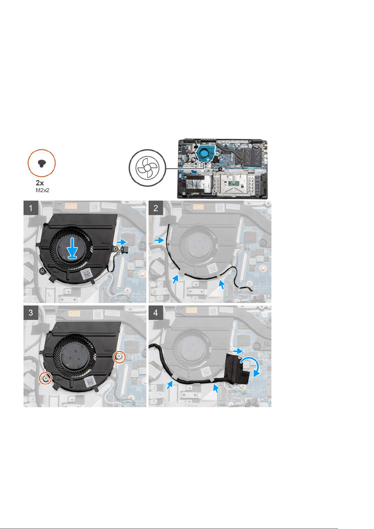
Installing the Fan Assembly
Prerequisites
If you are replacing a component, remove the existing component before performing the installation procedure.
About this task
The figure indicates the location of the fan assembly and provides a visual representation of the installation procedure.
Steps
1. Place the fan assembly onto the mounting points on the palmrest and connect the fan cable to the system board.
2. Route the antenna cables along the cable management routes on the fan assembly and connect the cables to the WLAN card.
3. Connect the fan connector to the system board.
4. Route the IO board cable along the cable management route on the fan assembly and connect it to the system board.
Disassembly and reassembly
49
Page 50

Next steps
1. Install the battery.
2. Install the base cover.
3. Install the SD card.
4. Follow the procedure in After working inside your computer.
Heatsink assembly
Removing the Heatsink Assembly - UMA
Prerequisites
1. Follow the procedure in before working inside your computer.
2. Remove the SD Card.
3. Remove the base cover.
4. Disconnect the battery.
About this task
The following images indicate the location of the heatsink and provide a visual representation of the removal procedure.
Steps
1. Loosen the seven captive screws that secure the heatsink to the system board.
2. Lift the heatsink assembly away from the computer.
Installing the Heatsink Assembly - Discrete
Prerequisites
If you are replacing a component, remove the existing component before performing the installation procedure.
50
Disassembly and reassembly
Page 51
About this task
The figure indicates the location of the heatsink and provides a visual representation of the installation procedure.
Steps
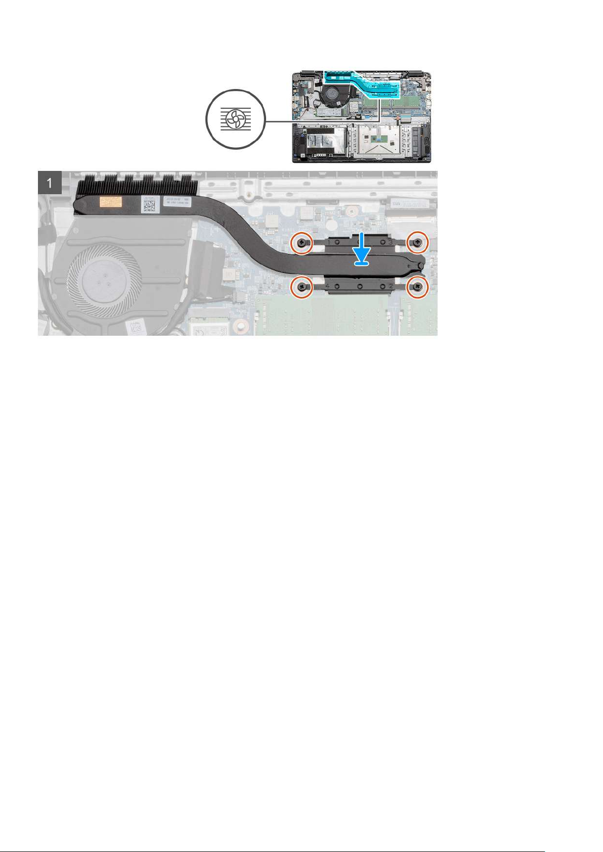
1. Place the heatsink onto the system board ensuring the mounting points on heatsink and system board align.
2. Tighten the seven captive screws to secure the heatsink to the system board.
Next steps
1. Install the battery.
2. Install the base cover.
3. Install the SD Card.
4. Follow the procedure in After working inside your computer.
Removing the Heatsink Assembly - UMA
Prerequisites
1. Follow the procedure in before working inside your computer.
2. Remove the SD Card.
3. Remove the base cover.
4. Disconnect the battery.
About this task
The following images indicate the location of the heatsink and provide a visual representation of the removal procedure.
Disassembly and reassembly
51
Page 52

Steps
1. Loosen the four captive screws that secure the heatsink to the system board.
2. Lift the heatsink assembly away from the computer.
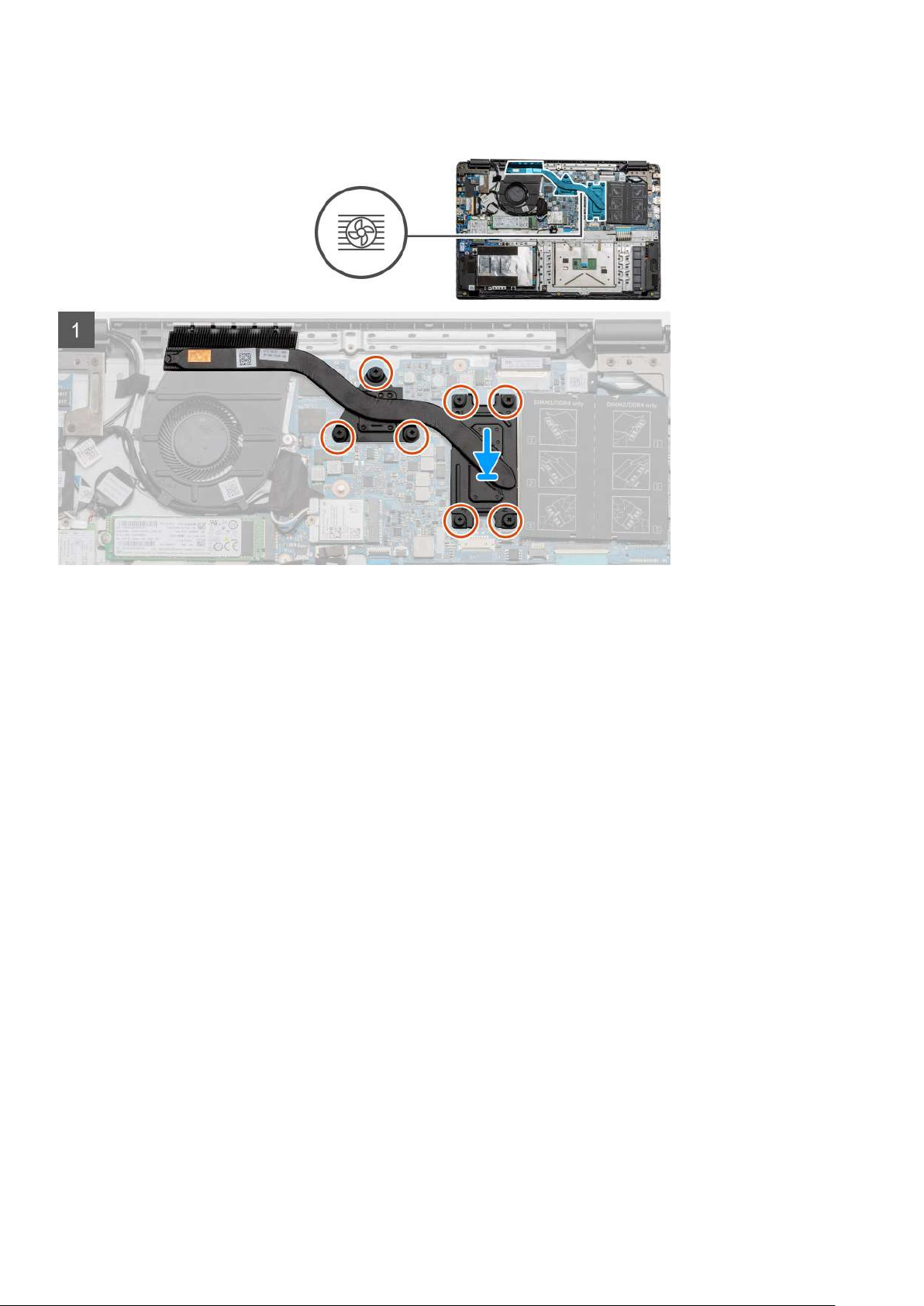
Installing the Heatsink Assembly - UMA
Prerequisites
If you are replacing a component, remove the existing component before performing the installation procedure.
About this task
The figure indicates the location of the heatsink and provides a visual representation of the installation procedure.
52
Disassembly and reassembly
Page 53
Steps
1. Place the heatsink onto the system board ensuring the mounting points on heatsink and system board align.
2. Tighten the four captive screws to secure the heatsink to the system board.
Next steps
1. Install the battery.
2. Install the base cover.
3. Install the SD Card.
4. Follow the procedure in After working inside your computer.
System board
Removing the system board - Discrete
Prerequisites
1. Follow the procedure in before working inside your computer.
2. Remove the SD Card.
3. Remove the base cover.
4. Disconnect the battery.
5. Remove the memory modules.
6. Remove the WWAN card.
7. Remove the WLAN card.
8. Remove the solid state drive.
9. Remove the heatsink.
About this task
The figure indicates the location of the system board and provides a visual representation of the removal procedure.
Disassembly and reassembly
53
Page 54
54 Disassembly and reassembly
Page 55

Steps
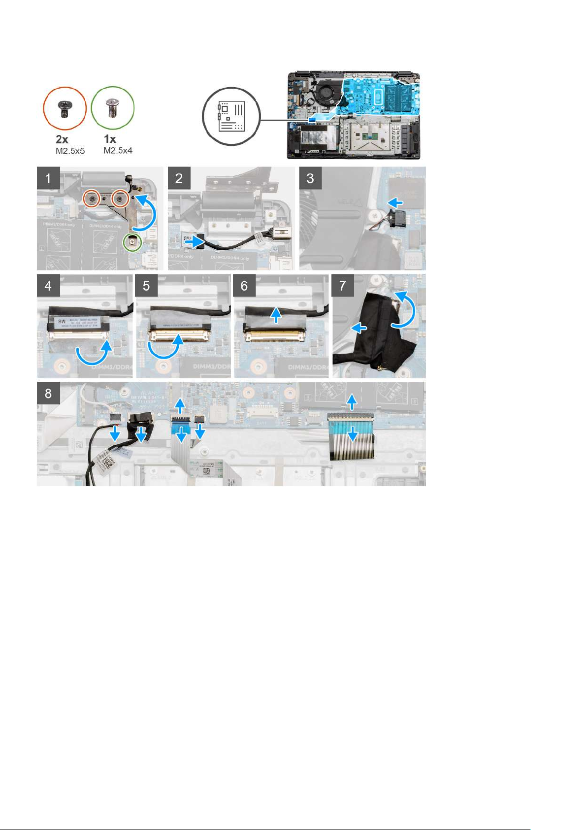
1. Remove the two (M2.5x5) and the single (M2.5x4) screws from the right hinge.
2. Disconnect the DC-in connector cable from the system board.
3. Disconnect the Fan assembly cable from the system board.
4. Peel back the adhesive tape covering the LCD cable.
5. Lift the latch that locks down the LCD cable onto the system board.
6. Disconnect the LCD cable from the system board.
7. Peel back the adhesive tape from over the IO board connector cable and disconnect the IO boards connector cable.
8. Disconnect the connector cables from the system board in the following order (left - right): Speaker, Touchpad, USB, Battery,
Keyboard.
Disassembly and reassembly
55
Page 56

9. Remove the two (M2x4) screws from the system board and the two (M2x5) screws holding the metal shield. Then lift and flip the
board downward.
10. Disconnect the cable that is connected to the daughterboard and lift and move the system board away from the computer.
Installing the system board - Discrete
Prerequisites
If you are replacing a component, remove the existing component before performing the installation procedure.
About this task
The figure indicates the location of the system board and provides a visual representation of the installation procedure.
56 Disassembly and reassembly
Page 57

Disassembly and reassembly 57
Page 58

Steps
1. Hold the system upside down, connect the cable connector from the system board to the daughterboard.
2. Fold the system board upright, and place it onto the system, aligning the screw posts from the palmrest. Place the metal shield onto
the USB port module and install the two (M2x5) screws. Install the two (M2x4) screws to secure the system board to the palmrest.
3. Fold the right hinge back, install the two (M2.5x5) and one (M2.5x4) to secure the hinge in place.
4. Connect the DC-in port connector back to the system board.
5. Connect the fan connector back to the system board.
6. Connect the LCD cable back to the system board.
7. Fold the LCD connectors latch to secure it in place.
8. Fold back the adhesive tape into the LCD connector.
9. Connect the IO board cable to the system board.
10. Connect the following cables in the following order (left - right): Speaker, Touchpad, USB, Battery, Keyboard.
Next steps
1. Install the Heatsink.
2. Install the WLAN card.
3. Install the WWAN card.
4. Install the Solid state drive.
5. Install the memory module.
6. Install the battery.
7. Install the base cover.
8. Install the SD Card.
9. Follow the procedure in After working inside your computer.
Removing the system board - UMA
Prerequisites
1. Follow the procedure in before working inside your computer.
2. Remove the SD Card.
3. Remove the base cover.
4. Disconnect the battery.
5. Remove the memory modules.
6. Remove the WLAN card.
7. Remove the WLAN card.
8. Remove the solid state drive.
9. Remove the heatsink.
About this task
The figure indicates the location of the system board and provides a visual representation of the removal procedure.
58
Disassembly and reassembly
Page 59

Disassembly and reassembly 59
Page 60

Steps
1. Remove the two (M2.5x5) and the single (M2.5x4) screws from the right hinge.
2. Disconnect the IO board connector cable from the system board.
3. Disconnect the Fan connector cable from the system board.
4. Peel back the adhesive tape from the LCD cable and disconnect the LCD cable from the system board.
5. Peel back the adhesive tape from the DC-in cable connector and disconnect the DC-in cable from the system board.
6. Remove the two (M2x5) screws from the metal shield covering the USB module.
7. Lift and take the metal shield away from the system.
8. Disconnect the connector cables from the system board in the following order (left - right): Speaker, Touchpad, USB, Battery,
Keyboard.
9. Remove the two (M2x4) screws from the system board and lift the board away from the computer.
Installing the system board - UMA
Prerequisites
If you are replacing a component, remove the existing component before performing the installation procedure.
About this task
The figure indicates the location of the system board and provides a visual representation of the installation procedure.
60
Disassembly and reassembly
Page 61

Disassembly and reassembly 61
Page 62

Steps
1. Place the system board onto the palmrest, aligning the screw posts to the mounting points on the palmrest. Install the two (M2x4)
screws to secure the system board to the palmrest.
2. Fold the right hinge back, install the two (M2.5x5) and one (M2.5x4) to secure the hinge in place.
3. Connect the fan connector back to the system board.
4. Connect the IO board cable to the system board.
5. Connect the LCD cable back to the system board and fold the adhesive tape back onto the LCD connector.
6. Connect the DC-in port connector back to the system board and fold the adhesive tape back onto the DC-in connector.
7. Place the metal shield onto the USB port module.
8. Install the two (M2x5) screws to secure the metal shield.
9. Connect the following cables in the following order (left - right): Speaker, Touchpad, USB, Battery, Keyboard.
Next steps
1. Install the Heatsink.
2. Install the WLAN card.
3. Install the WWAN card.
4. Install the Solid state drive.
5. Install the memory module.
6. Install the battery.
7. Install the base cover.
62
Disassembly and reassembly
Page 63

8. Install the SD Card.
9. Follow the procedure in After working inside your computer.
IO Board
Removing the IO Board
Prerequisites
1. Follow the procedure in before working inside your computer.
2. Remove the SD Card.
3. Remove the base cover.
4. Disconnect the battery.
5. Remove the WLAN card.
6. Remove the WWAN card.
7. Remove the solid state drive.
NOTE: Hall Sensor is a part of the IO board and the entire IO board needs to be replaced if the Hall Sensor is faulty.
About this task
The following images indicate the location of the memory module and provide a visual representation of the removal procedure.
Disassembly and reassembly
63
Page 64

Steps
1. Remove the three (M2x3) screws from the left hinge and lift the hinge up.
2. Peel back the adhesive tape covering the IO board connector cable and disconnect it from the system board.
3. Disconnect the cable connectors from the IO board in the following order (left - right): USB cable, Coin-cell battery cable, third
connector.
4. Remove the single (M2x5) screw that is holding the IO board in place and lift the module away from the computer.
Installing the IO Board
Prerequisites
If you are replacing a component, remove the existing component before performing the installation procedure.
About this task
The figure indicates the location of the IO board and provides a visual representation of the installation procedure.
Steps
1. Place the IO board onto the mounting points on the palmrest and secure it using the single (M2x5) screw.
2. Connect the three cable connectors to the connectors on lower right side of the IO board, Using a single (M2x3) screw, install the
WWAN card and secure it in place.
3. Route the IO Board connector cable through the routing points under the fan assembly and connect the cable to the connector on the
system board. Fold the adhesive tape back onto the IO Board connector on the system board.
4. Using the three (M2x3) screws, close and secure the left hinge to the palmrest.
64
Disassembly and reassembly
Page 65
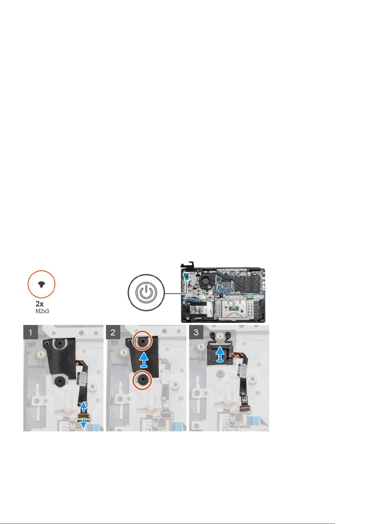
Next steps
1. Install the WLAN card.
2. Install the WWAN card.
3. Install the Solid state drive.
4. Install the battery.
5. Install the base cover.
6. Install the SD Card.
7. Follow the procedure in After working inside your computer.
Power button
Removing the Power Button
Prerequisites
1. Follow the procedure in before working inside your computer.
2. Remove the SD Card.
3. Remove the base cover.
4. Disconnect the battery.
5. Remove the WLAN card.
6. Remove the WWAN card.
7. Remove the IO board.
8. Remove the solid state drive.
About this task
The figure indicates the location of the Power Button and provides a visual representation of the removal procedure.
Steps
1. Disconnect the power button connector cable from the daughterboard module.
2. Remove the two (M2x3) screws that secure the shield over the power button module.
3. Lift the Power Button module away from the computer.
Disassembly and reassembly
65
Page 66

Installing the Power Button
Prerequisites
If you are replacing a component, remove the existing component before performing the installation procedure.
About this task
The figure indicates the location of the power button and provides a visual representation of the installation procedure.
Steps
1. Place the Power Button module onto the mounting points on the palmrest and connect the cable to the connector on the system
board.
2. Place the plastic cover on top of the power button module.
3. Place the shield on top of the power button module and install the two (M2x3) screws to secure the shield onto the power button.
4. Connect the cable connector to the daughterboard module.
Next steps
1. Install the WLAN card.
2. Install the WWAN card.
3. Install the Solid state drive.
4. Install the battery.
5. Install the base cover.
6. Install the SD Card.
7. Follow the procedure in After working inside your computer.
66
Disassembly and reassembly
Page 67
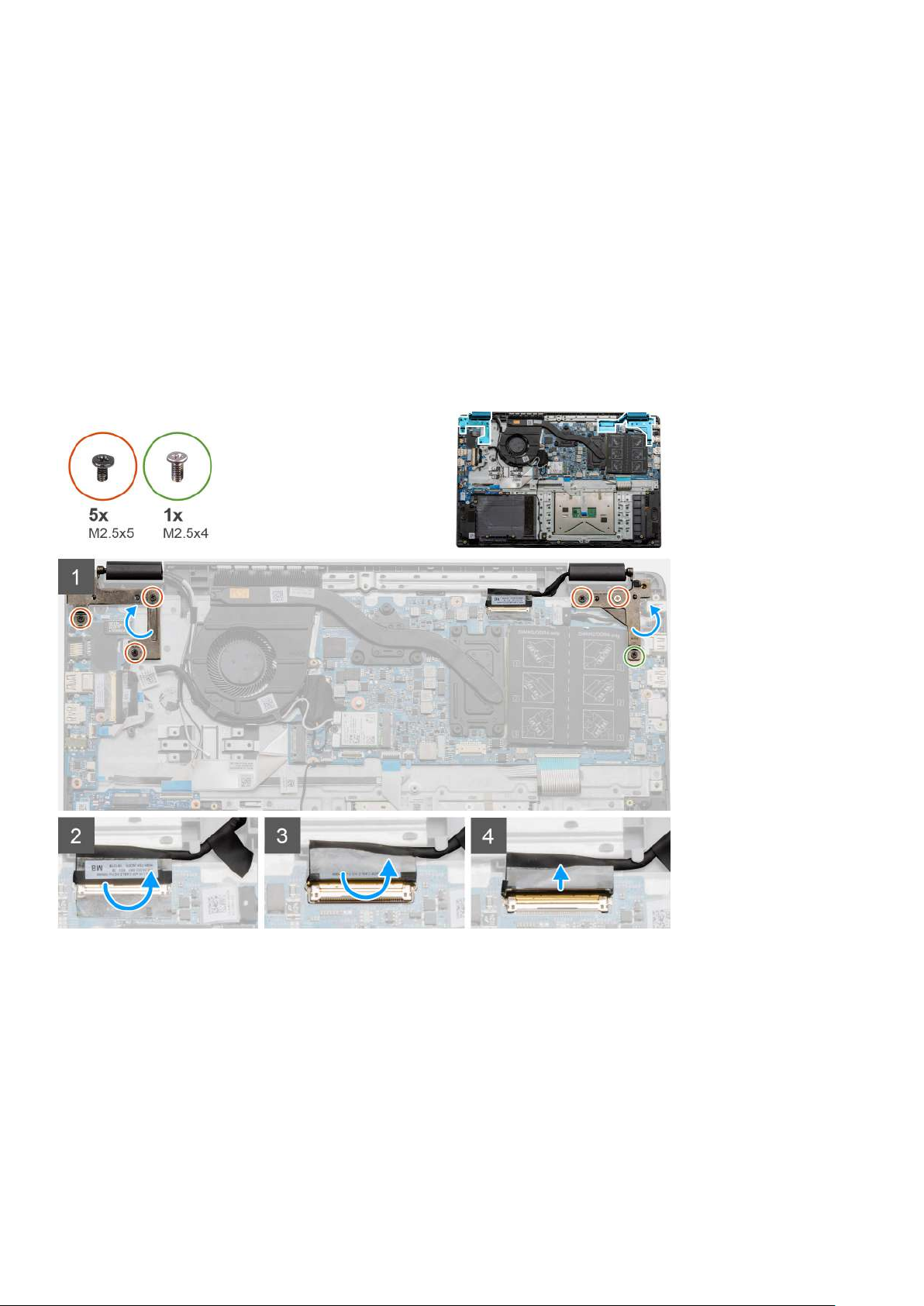
Display assembly
Removing the LCD Assembly
Prerequisites
1. Follow the procedure in before working inside your computer.
2. Remove the SD Card.
3. Remove the base cover.
4. Disconnect the battery.
About this task
The figure indicates the location of the LCD Assembly and provides a visual representation of the removal procedure.
Disassembly and reassembly 67
Page 68
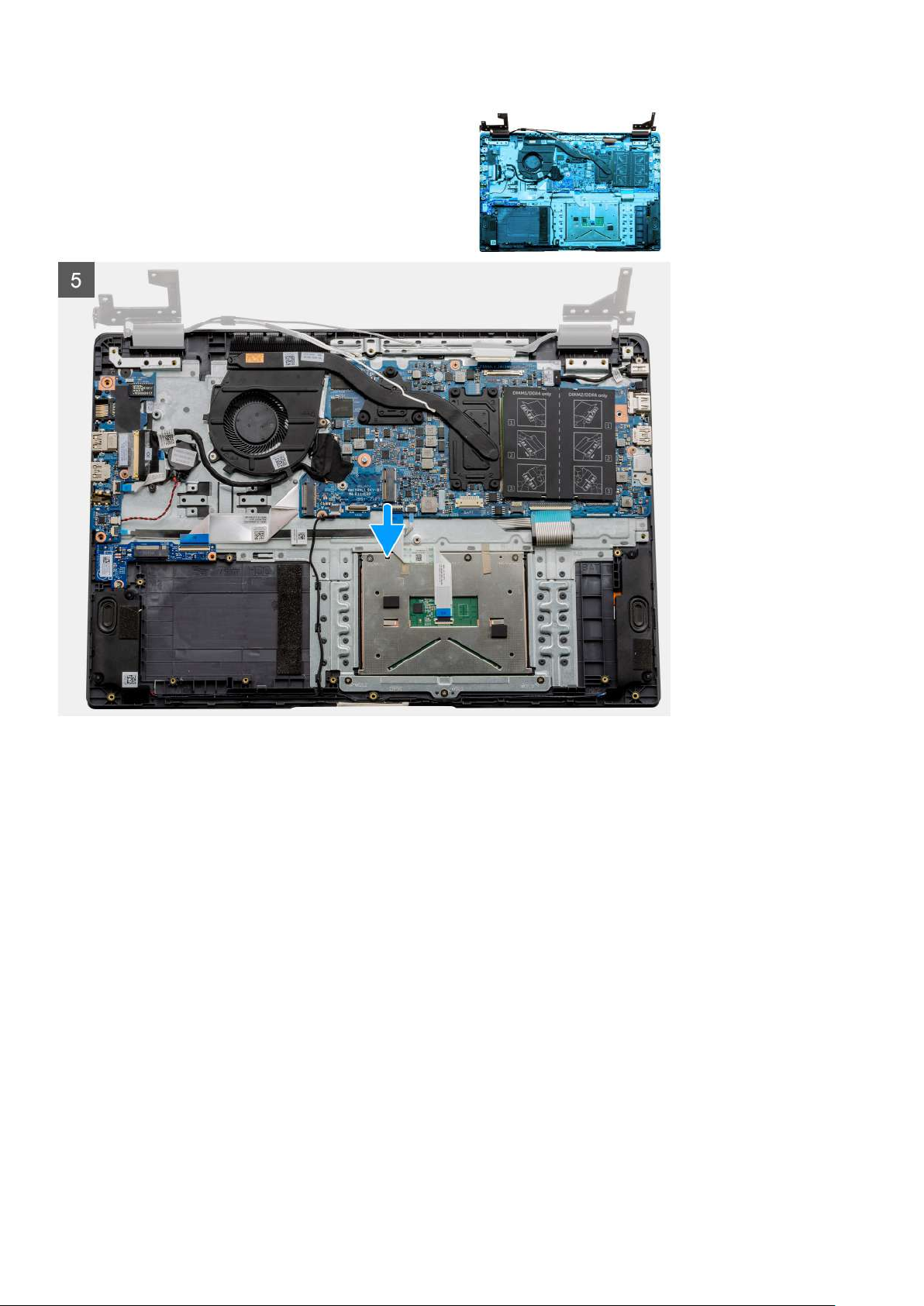
68 Disassembly and reassembly
Page 69
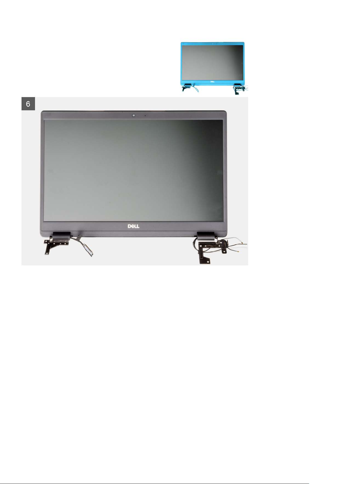
Steps
1. Remove the five M2.5x5 screws from both the hinges followed by the single M2.5x4 from the right hinge. Lift and fold the hinges
backwards.
2. Peel back the adhesive tape covering the LCD cable.
3. Fold the adhesive tape away from the LCD cable.
4. Remove the LCD cable and lift it away from the computer.
5. Move the system away from the LCD assembly.
Installing the LCD Assembly
Prerequisites
If you are replacing a component, remove the existing component before performing the installation procedure.
About this task
The figure indicates the location of the LCD Assembly and provides a visual representation of the installation procedure.
Disassembly and reassembly
69
Page 70

70 Disassembly and reassembly
Page 71
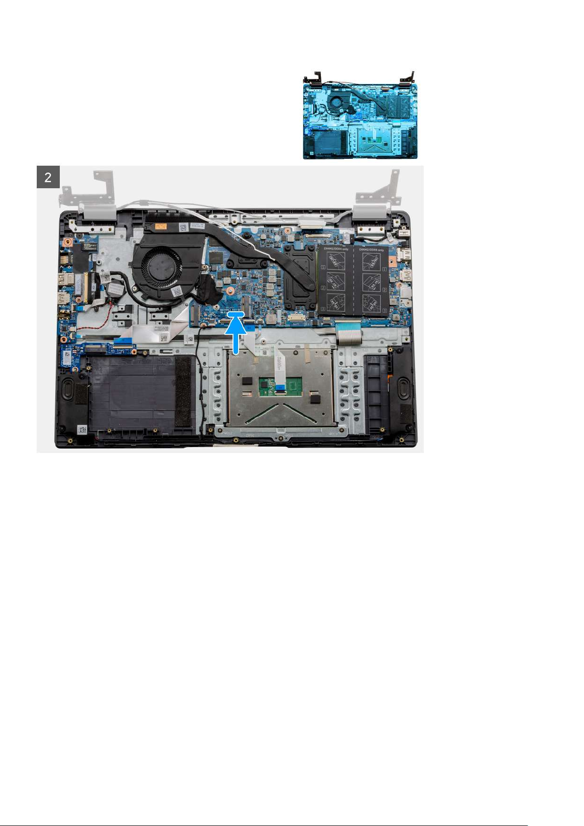
Disassembly and reassembly 71
Page 72
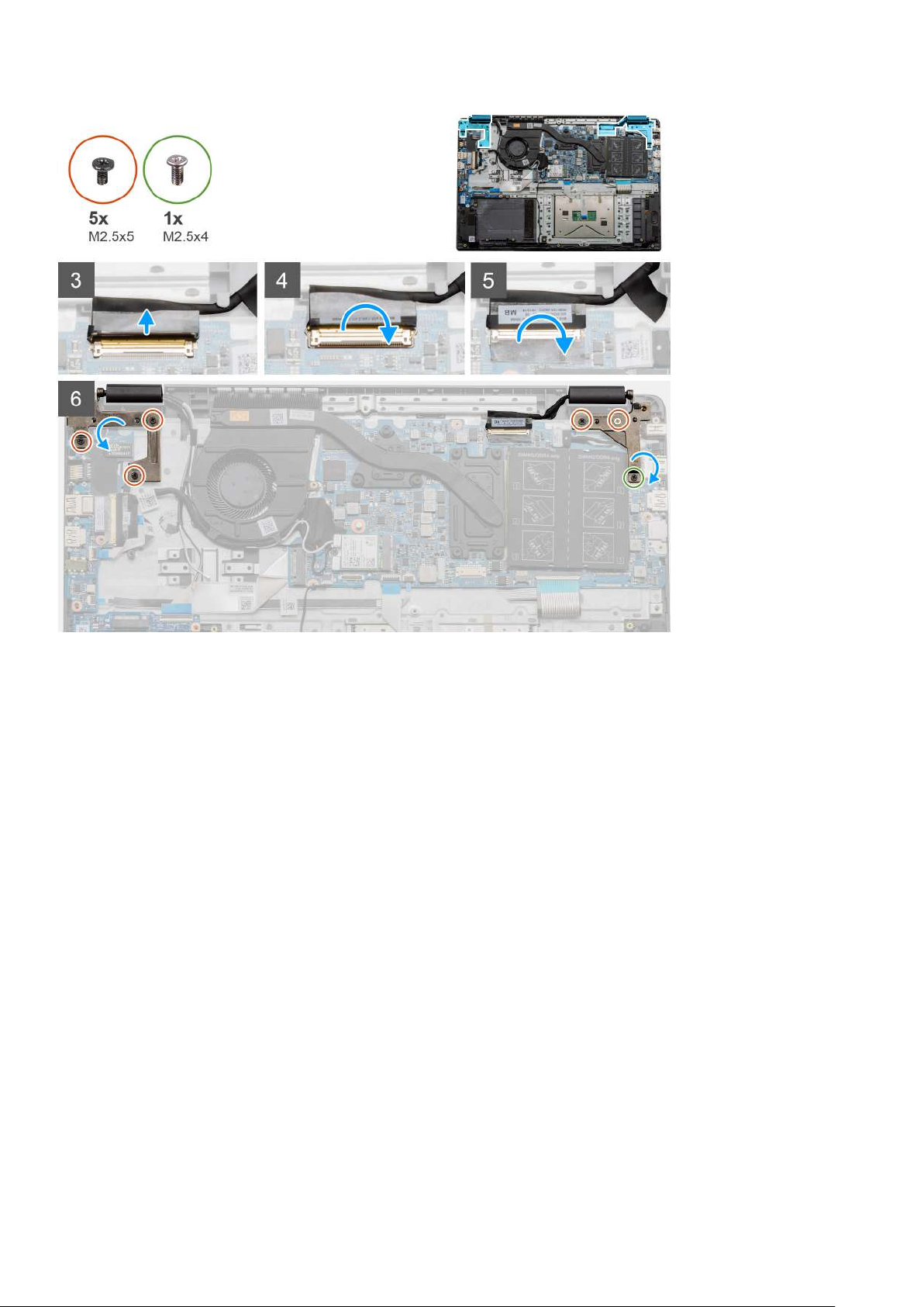
Steps
1. Place the display assembly on a clean and flat surface.
2. Align and place the palmrest and keyboard assembly on the display assembly.
3. Using the alignment posts, close the display hinges.
4. Connect the display cable to the system board and adhere the tape to secure the display cable.
5. Place the EDP metal bracket on the display cable connector.
6. Install the six (M2.5x5) screws that secure the display hinges to the chassis of your computer.
Next steps
1. Install the battery.
2. Install the base cover.
3. Install the SD card.
4. Follow the procedure in After working inside your computer.
Palmrest assembly
Removing the Palmrest Assembly
Prerequisites
1. Follow the procedure in before working inside your computer.
2. Remove the SD card.
3. Remove the base cover.
4. Remove the battery.
5. Remove the WLAN card.
72
Disassembly and reassembly
Page 73
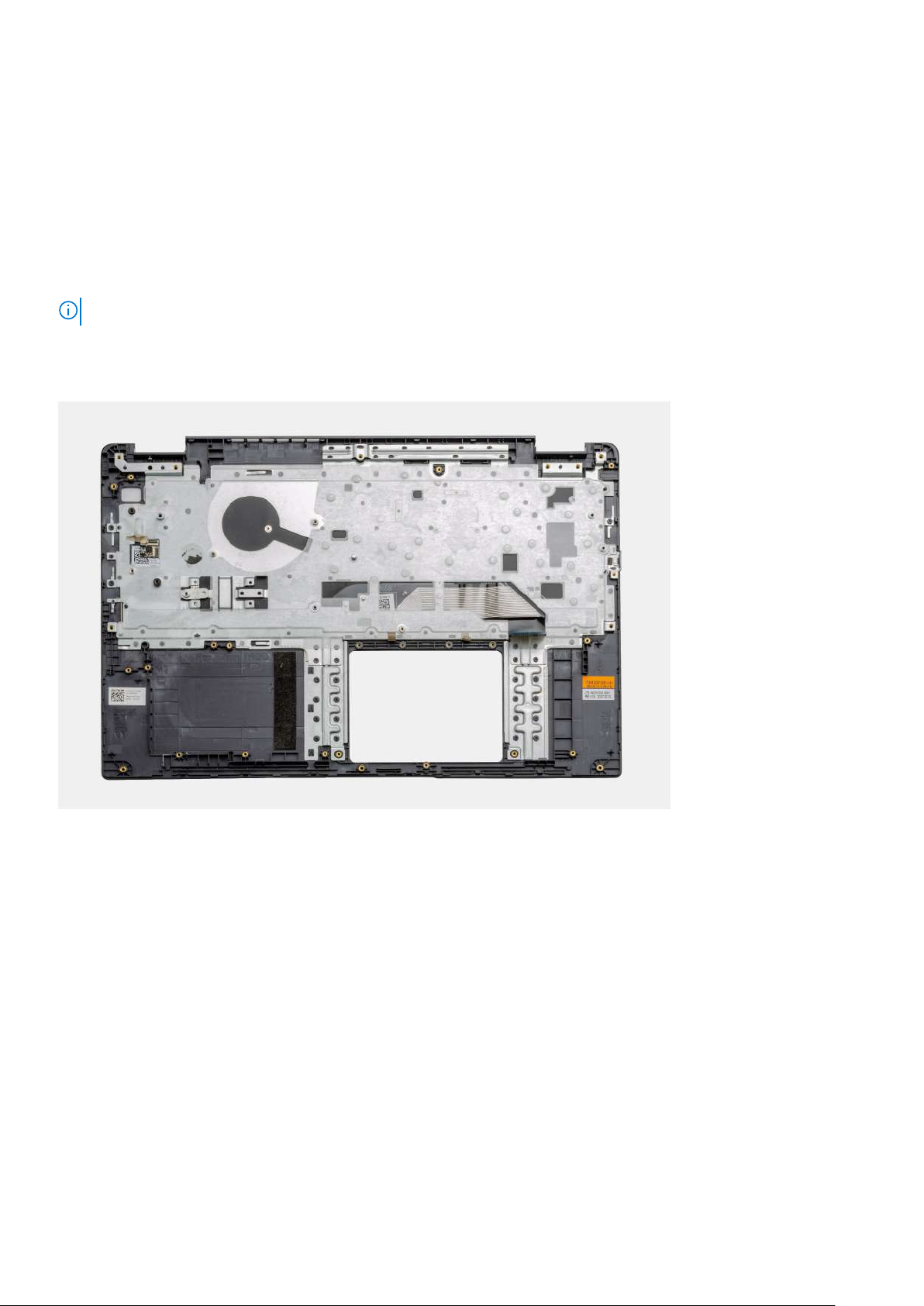
6. Remove the WWAN card.
7. Remove the coin-cell battery.
8. Remove the memory modules.
9. Remove the DC-in.
10. Remove the solid state drive.
11. Remove the hard drive.
12. Remove the touchpad.
13. Remove the speakers.
14. Remove the heatsink.
15. Remove the system board.
NOTE: The system board can be removed along with the heat sink.
About this task
The figure indicates the location of the Palmrest Assembly and provides a visual representation of the removal procedure.
Steps
Once the required parts are removed, the bare palmrest assembly can be accessed and removed.
Next steps
1. Install the system board
2. Install the heatsink.
3. Install the speakers.
4. Install the touchpad.
5. Install the hard drive.
6. Install the solid state drive.
7. Install the DC-in.
8. Install the memory modules.
9. Install the coin-cell battery.
10. Install the WWAN card.
11. Install the WLAN card.
12. Install the battery.
13. Install the base cover.
Disassembly and reassembly
73
Page 74

14. Install the SD card SD card.
1. Follow the procedure in after working inside your computer.
74 Disassembly and reassembly
Page 75

5
Troubleshooting
Enhanced Pre-Boot System Assessment (ePSA) diagnostics
About this task
The SupportAssist diagnostics (also known as system diagnostics) performs a complete check of your hardware. The SupportAssist
diagnostics is embedded with the BIOS and is launched by the BIOS internally. The embedded system diagnostics provides a set of options
for particular devices or device groups allowing you to:
• Run tests automatically or in an interactive mode
• Repeat tests
• Display or save test results
• Run thorough tests to introduce additional test options to provide extra information about the failed device(s)
• View status messages that inform you if tests are completed successfully
• View error messages that inform you of problems encountered during testing
NOTE:
The SupportAssist window displays, listing all devices detected in the computer. The diagnostics starts running
the tests on all the detected devices.
Running SupportAssist diagnostics
Steps
1. Turn on your computer.
2. As the computer boots, press the F12 key as the Dell logo appears.
3. On the boot menu screen, select the Diagnostics option.
4. Click the arrow at the bottom left corner.
Diagnostics front page is displayed.
5. Click the arrow in the lower-right corner to go to the page listing.
The items detected are listed.
6. To run a diagnostic test on a specific device, press Esc and click Yes to stop the diagnostic test.
7. Select the device from the left pane and click Run Tests.
8. If there are any issues, error codes are displayed.
Note the error code and validation number and contact Dell.
SupportAssist diagnostic User Interface
SupportAssist diagnostic User Interface
About this task
This section contains information on Support Assist Basic and Advanced Screen.
SupportAssist opens the basic screen on start. You can switch to the advanced screen using the icon at the bottom left of the screen.
The advanced screen shows detected devices in a tiled format. Specific tests can be included or excluded only in the advanced mode. The
Basic Screen has minimal controls which allows easy navigation for the user to start or stop the diagnostics.
System diagnostic lights
Battery-status light
Troubleshooting 75
Page 76

Indicates the power and battery-charge status.
Solid white — Power adapter is connected and the battery has more than 5 percent charge.
Amber — Computer is running on battery and the battery has less than 5 percent charge.
Off
• Power adapter is connected and the battery is fully charged.
• Computer is running on battery and the battery has more than 5 percent charge.
• Computer is in sleep state, hibernation, or turned off.
The power and battery-status light blinks amber along with beep codes indicating failures.
For example, the power and battery-status light blinks amber two times followed by a pause, and then blinks white three times followed by
a pause. This 2,3 pattern continues until the computer is turned off indicating no memory or RAM is detected.
The following table shows different power and battery-status light patterns and associated problems.
Table 3. LED codes
Diagnostic light codes Problem description
2,1 Processor failure
2,2 System board: BIOS or ROM (Read-Only Memory) failure
2,3 No memory or RAM (Random-Access Memory) detected
2,4 Memory or RAM (Random-Access Memory) failure
2,5 Invalid memory installed
2,6 System-board or chipset error
2,7 Display failure
2,8 LCD power rail failure. Replace system board
3,1 Coin-cell battery failure
3,2 PCI, video card/chip failure
3,3 Recovery image not found
3,4 Recovery image found but invalid
3,5 Power-rail failure
3,6 System BIOS Flash incomplete
3,7 Management Engine (ME) error
Camera status light: Indicates whether the camera is in use.
• Solid white — Camera is in use.
• Off — Camera is not in use.
Caps Lock status light: Indicates whether Caps Lock is enabled or disabled.
• Solid white — Caps Lock enabled.
• Off — Caps Lock disabled.
WiFi power cycle
About this task
If your computer is unable to access the internet due to WiFi connectivity issues a WiFi power cycle procedure may be performed. The
following procedure provides the instructions on how to conduct a WiFi power cycle:
NOTE: Some ISPs (Internet Service Providers) provide a modem/router combo device.
76 Troubleshooting
Page 77

Steps
1. Turn off your computer.
2. Turn off the modem.
3. Turn off the wireless router.
4. Wait for 30 seconds.
5. Turn on the wireless router.
6. Turn on the modem.
7. Turn on your computer.
Troubleshooting 77
Page 78

6
Getting help
Topics:
• Contacting Dell
Contacting Dell
Prerequisites
NOTE: If you do not have an active Internet connection, you can find contact information on your purchase invoice,
packing slip, bill, or Dell product catalog.
About this task
Dell provides several online and telephone-based support and service options. Availability varies by country and product, and some services
may not be available in your area. To contact Dell for sales, technical support, or customer service issues:
Steps
1. Go to Dell.com/support.
2. Select your support category.
3. Verify your country or region in the Choose a Country/Region drop-down list at the bottom of the page.
4. Select the appropriate service or support link based on your need.
78 Getting help
 Loading...