

Page 1

Dell™ OptiPlex™ 740
Quick Reference Guide
Models DCSM, DCNE, DCCY
www.dell.com | support.dell.com
Page 2

Notes, Notices, and Cautions
NOTE: A NOTE indicates important information that helps you make better use of
your computer.
NOTICE: A NOTICE indicates either potential damage to hardware or loss of data
and tells you how to avoid the problem.
CAUTION: A CAUTION indicates a potential for property damage, personal injury,
or death.
If you purchased a Dell™ n Series computer, any references in this document to
®
Microsoft
Windows® operating systems are not applicable.
____________________
Information in this document is subject to change without notice.
© 2008 Dell Inc. All rights reserved.
Reproduction in any manner whatsoever without the written permission of Dell Inc. is strictly
forbidden.
Trademarks used in this text: Dell, OptiPlex, and the DELL logo are trademarks of Dell Inc.; Microsoft,
Windows, Windows Vista, and the W i ndows Vista Start Button are registered trademarks of Microsoft
Corporation.
Other trademarks and trade names may be used in this document to refer to either the entities claiming
the marks and names or their products. Dell Inc. disclaims any proprietary interest in trademarks and
trade names other than its own.
Models DCSM, DCNE, DCCY
January 2008 P/N HX166 Rev. A01
Page 3

Contents
Finding Information . . . . . . . . . . . . . . . . . . . . 5
Setting Up Your Computer
System Views
. . . . . . . . . . . . . . . . . . . . . . 14
. . . . . . . . . . . . . . . . 10
Mini Tower Computer — Front View
Mini Tower Computer — Back View
Mini Tower Computer — Back-Panel
Connectors
. . . . . . . . . . . . . . . . . . . . . 19
Desktop Computer — Front View
Desktop Computer — Back View
Desktop Computer — Back-Panel
Connectors
. . . . . . . . . . . . . . . . . . . . . 24
Small Form Factor Computer — Front View
Small Form Factor Computer — Back View
Small Form Factor Computer — Back-Panel
Connectors
Removing the Computer Cover
. . . . . . . . . . . . . . . . . . . . . 30
. . . . . . . . . . . . . 32
. . . . . . . . 14
. . . . . . . . 17
. . . . . . . . . 21
. . . . . . . . . 23
. . . . 26
. . . . 29
Inside Your Computer
Before You Begin
Mini Tower Computer
Desktop Computer
. . . . . . . . . . . . . . . . . . 32
. . . . . . . . . . . . . . . . 34
. . . . . . . . . . . . . . . . . 36
Small Form Factor Computer
. . . . . . . . . . . . . . . . . . 39
Mini Tower Computer
Desktop Computer
. . . . . . . . . . . . . . . . 39
. . . . . . . . . . . . . . . . . 43
Small Form Factor Computer
. . . . . . . . . . . . 38
. . . . . . . . . . . . 47
Contents 3
Page 4

Solving Problems . . . . . . . . . . . . . . . . . . . . 50
Dell Diagnostics
System Lights
Diagnostic Lights
Beep Codes
. . . . . . . . . . . . . . . . . . . 51
. . . . . . . . . . . . . . . . . . . . 54
. . . . . . . . . . . . . . . . . . . . . 55
. . . . . . . . . . . . . . . . . . . . . 59
Resolving Software and Hardware
Incompatibilities
Restoring Your Operating System
. . . . . . . . . . . . . . . . . . 60
. . . . . . . . . . 61
Reinstalling Your Microsoft Windows
Operating System
Using the Drivers and Utilities Media
. . . . . . . . . . . . . . . . . . 63
. . . . . . . . 67
Index . . . . . . . . . . . . . . . . . . . . . . . . . . . . . . . 71
4 Contents
Page 5

Finding Information
NOTE: Some features or media may be optional and may not ship with your
computer. Some features or media may not be available in certain countries.
NOTE: Additional information may ship with your computer.
What Are You Looking For? Find It Here
• A diagnostic program for my computer
• Drivers for my computer
• My computer documentation
• My device documentation
• Desktop System Software (DSS)
Drivers and Utilities Media
NOTE: The Drivers and Utilities media may
be optional and may not ship with your
computer.
Documentation and drivers are already
installed on your computer. You can use
the Drivers and Utilities media to reinstall
drivers (see "Using the Drivers and
Utilities Media" on page 67), to run the
Dell Diagnostics (see "Dell Diagnostics"
on page 51), or to access your
documentation.
Readme files may be included on your
media (CD or DVD) to provide the most
current updates about technical changes
to your computer or advanced technicalreference material for technicians or
experienced users.
NOTE: Drivers and documentation updates
can be found at support.dell.com.
Quick Reference Guide 5
Page 6
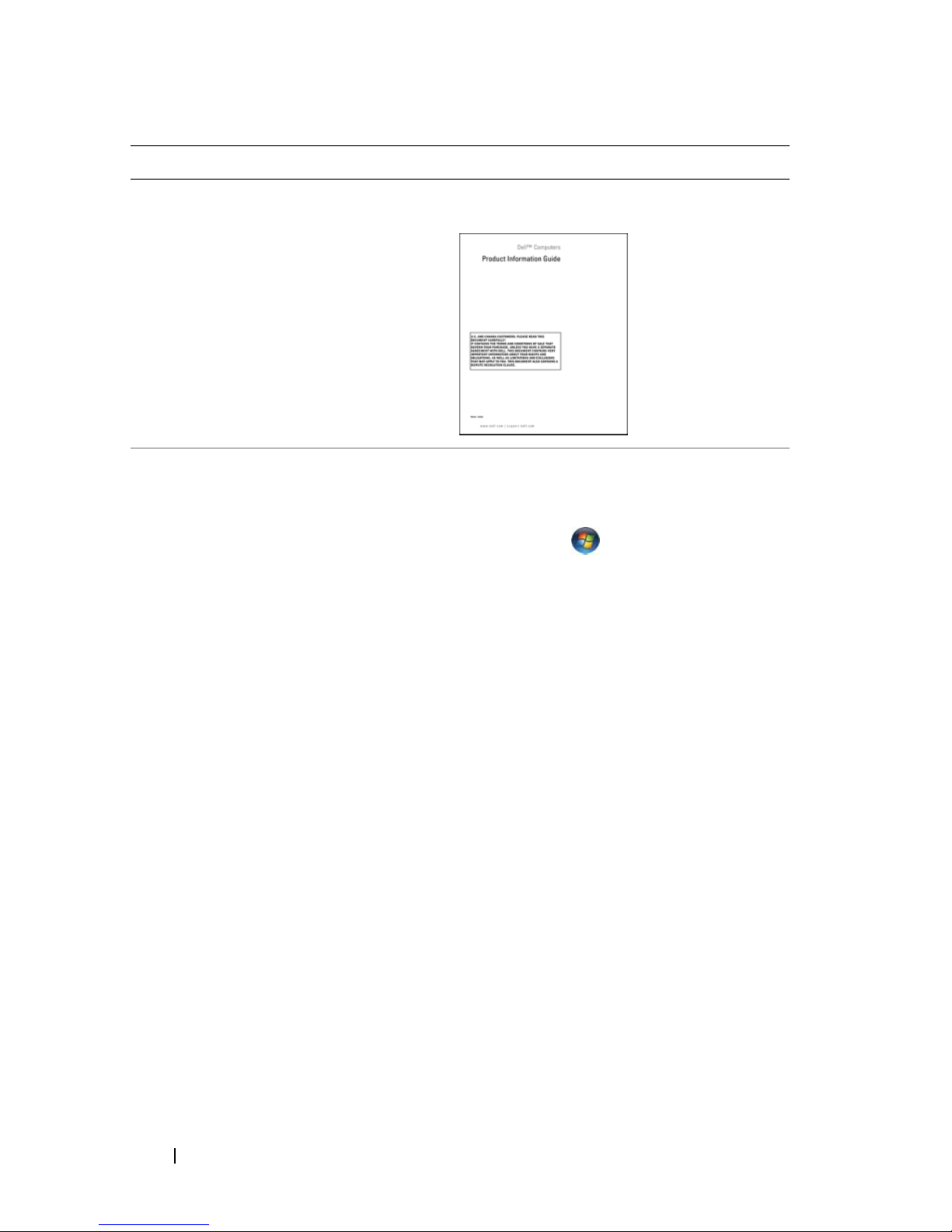
What Are You Looking For? Find It Here
• Warranty information
• Terms and Conditions (U.S. only)
• Safety instructions
• Regulatory information
• Ergonomics information
• End User License Agreement
• How to remove and replace parts
• Specifications
• How to configure system settings
• How to troubleshoot and solve
problems
Dell™ Product Information Guide
Dell™ OptiPlex™ User’s Guide
Microsoft Windows Help and Support
Center
1
Click
Start
Dell User and System Guides
Guides
2
Click the
.
→
Help and Support→
User’s Guide
→
for your
System
computer.
The User’s Guide is also available on the
optional Drivers and Utilities media.
6 Quick Reference Guide
Page 7
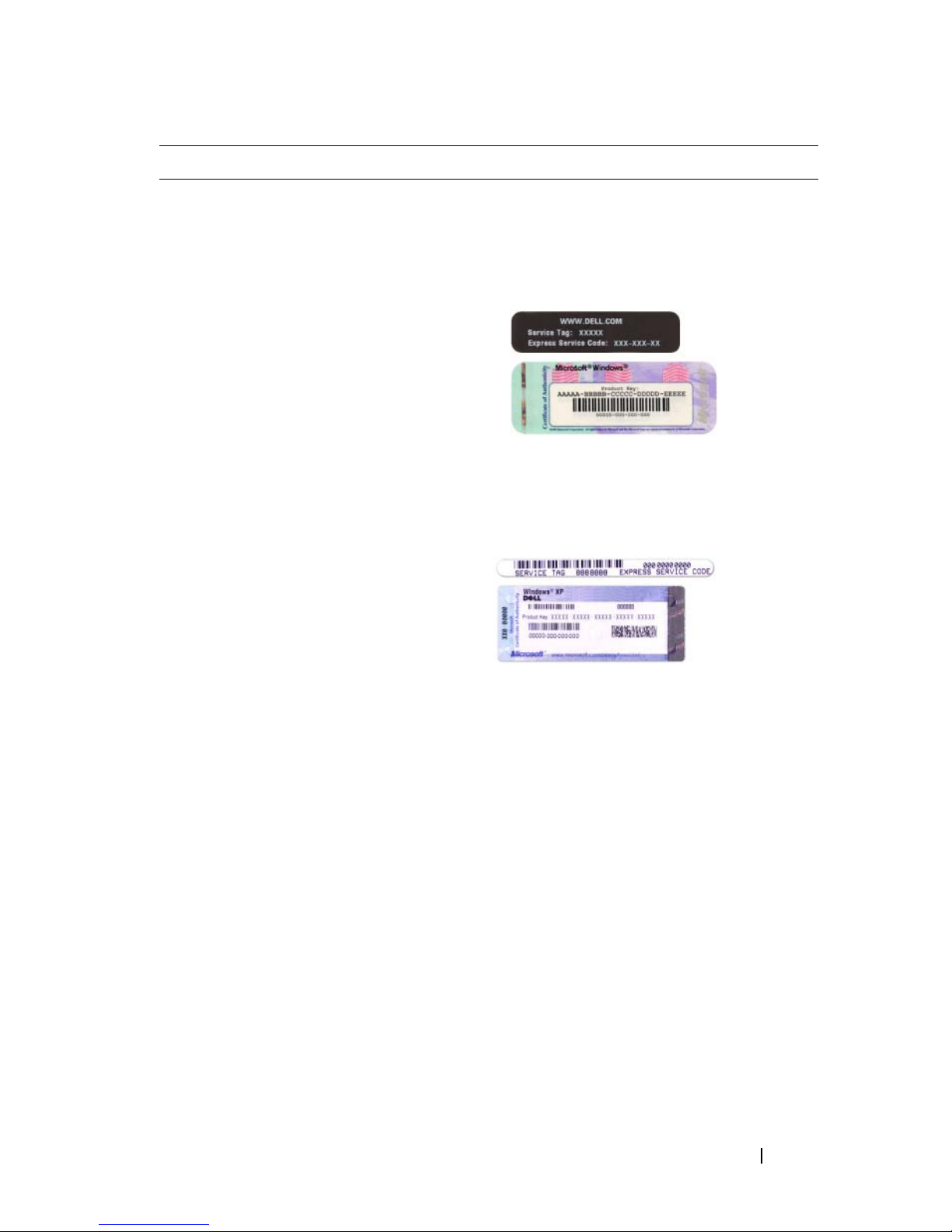
What Are You Looking For? Find It Here
• Service Tag and Express Service Code
• Microsoft Windows License Label
Service Tag and Microsoft® Windows®
License
These labels are located on your
computer.
• Use the Service Tag to identify your
computer when you use
support.dell.com
or contact support.
• Enter the Express Service Code to direct
your call when contacting support.
Quick Reference Guide 7
Page 8

What Are You Looking For? Find It Here
• How to reinstall my operating system
Operating System Media
NOTE: The Operating System media may
be optional and may not ship with your
computer.
The operating system is already installed
on your computer. To reinstall your
operating system, use the Operating
System media. See "Reinstalling Your
Microsoft Windows Operating System"
on page 63.
After you reinstall your operating system,
you can use the optional Drivers and
Utilities media to reinstall drivers for the
devices that came with your computer.
Your operating system product key label is
located on your computer.
NOTE: The color of your media varies
based on the operating system you ordered.
8 Quick Reference Guide
Page 9

What Are You Looking For? Find It Here
• Solutions — Troubleshooting hints and
tips, articles from technicians,
frequently asked questions, and online
courses
• Community — Online discussion with
other Dell customers
• Upgrades — Upgrade information for
components, such as memory, the hard
drive, and the operating system
• Customer Care — Contact
information, service call and order
status, warranty, and repair information
• Service and support — Service call
status and support history, service
contract, online discussions with
technical support
• Reference — Computer
documentation, details on my
computer configuration, product
specifications, and white papers
Dell Support Website — support.dell.com
NOTE: Select your region or business
segment to view the appropriate support
site.
• Downloads — Certified drivers,
patches, and software updates
• Desktop System Software (DSS) — If
you reinstall the operating system for
your computer, you should also reinstall
the DSS utility. DSS provides critical
updates for your operating system and
support for Dell™ 3.5-inch USB floppy
drives, processors, optical drives, and
USB devices. DSS is necessary for
correct operation of your Dell
computer. The software automatically
detects your computer and operating
system and installs the updates
appropriate for your configuration.
To download Desktop System Software:
1
Go to
support.dell.com
, select your
region or business segment, and enter
your Service Tag.
2
Select
click
3
Click your operating system and search
for the keyword
Software
Drivers & Downloads
Go
.
Desktop System
.
and
NOTE: The support.dell.com user interface
may vary dependent upon your selections.
Quick Reference Guide 9
Page 10
What Are You Looking For? Find It Here
• How to use Windows Vista® or
Windows
• How to work with programs and files
• How to personalize my desktop
®
XP
Windows Help and Support Center
1
To access Windows Help and Support:
•
In Windows Vista
Help and Support
In Windows XP
•
and Support
2
Type a word or phrase that describes
your problem and click the arrow icon.
3
Click the topic that describes your
problem.
4
Follow the instructions on the screen.
, click Start
, click
.
.
Start
Setting Up Your Computer
CAUTION: Before performing any of the procedures in this section, follow the
safety instructions in Product Information Guide.
NOTICE: If your computer has an expansion card installed (such as a modem
card), connect the appropriate cable to the card, not to the connector on the back
panel.
→
→ Help
NOTICE: To help allow the computer to maintain proper operating temperature,
ensure that you do not place the computer too close to a wall or other storage
compartment that might prevent air circulation around the chassis.
NOTE: Before you install any devices or software that did not ship with your
computer, read the documentation that came with the device or software, or
contact the vendor to verify that the device or software is compatible with your
computer and operating system.
10 Quick Reference Guide
Page 11
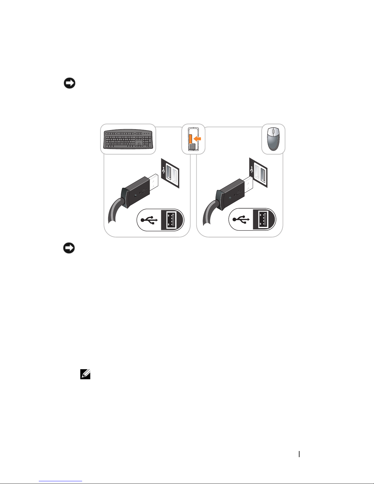
You must complete all the steps to properly set up your computer. See the
appropriate figures that follow the instructions.
NOTICE: Do not attempt to operate a PS/2 mouse and a USB mouse
simultaneously.
1
Connect the keyboard and mouse.
NOTICE: Do not connect a telephone line to the network adapter connector.
Voltage from telephone communications can cause damage to the network adapter.
2
Connect the telephone line or network cable.
Insert the network cable, not the telephone line, into the network
connector. If you have an optional modem, connect the telephone line to
the modem.
3
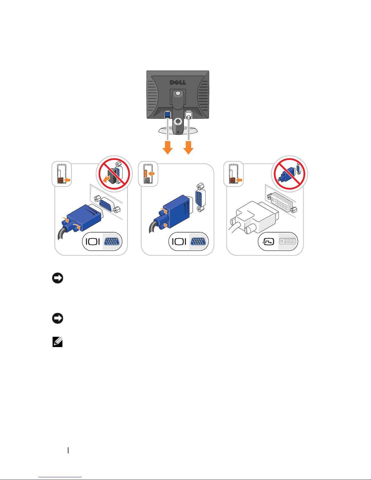
Connect the monitor using ONLY ONE of the following cables: the white
DVI cable or the blue VGA cable (do not connect both cables to the same
computer).
Align and gently insert the monitor cable to avoid bending connector pins.
Tighten the thumbscrews on the cable connectors.
NOTE: Some monitors have the video connector underneath the back of the
screen. See the documentation that came with your monitor for its connector
locations.
Quick Reference Guide 11
Page 12
4
Connect the speakers.
NOTICE: To avoid damaging your computer, set the manual voltage-selection
switch (on the back of the computer, if your computer has a voltage selection
switch) for the voltage that most closely matches the AC power available in your
location.
NOTICE: In Japan, the voltage selection switch must be set to the 115-V position
even though the AC power available in Japan is 100 V.
NOTE: Your computer’s power supply may or may not have a voltage selection
switch.
5
Verify that the voltage selection switch is set correctly for your location.
Your computer has a manual voltage-selection switch. Computers with a
voltage selection switch on the back panel must be manually set to operate
at the correct operating voltage.
12 Quick Reference Guide
Page 13

6
Connect power cables to the computer, monitor, and devices and connect
the other ends of the power cables to electrical outlets.
Quick Reference Guide 13
Page 14

System Views
Mini Tower Computer — Front View
10
9
8
1
2
3
4
5
6
7
14 Quick Reference Guide
Page 15

1 optical drive
(optional)
Insert an optical drive (if supported) into this bay.
2 floppy drive
bay (optional)
3 USB 2.0
connectors (2)
4 LAN indicator
light
5 diagnostic
lights
6 power button Press this button to turn on the computer.
Can contain a floppy drive or a optional media card reader.
Use the front USB connectors for devices that you connect
occasionally, such as joysticks or cameras, or for bootable USB
devices (
more information on booting to a USB device).
It is recommended that you use the back USB connectors for
devices that typically remain connected, such as printers and
keyboards.
This light indicates that a local area network (LAN)
connection is established.
Use the lights to help you troubleshoot a computer problem
based on the diagnostic code. For more information, see
"Diagnostic Lights" on page 55.
see "System Setup" in your online User’s Guide for
NOTICE: To avoid losing data, do not turn off the computer
by pressing the power button. Instead, perform an
operating system shutdown. See "Turning Off Your
Computer" in your online User’s Guide for more
information.
NOTICE: If your operating system has ACPI enabled,
when you press the power button the computer will
perform an operating system shutdown.
Quick Reference Guide 15
Page 16

7 power light The power light illuminates and blinks or remains solid to
indicate different operating modes:
• No light — The computer is turned off.
• Steady green — The computer is in a normal operating state.
• Blinking green — The computer is in a power-saving mode.
• Blinking or solid amber — See "Power Problems" in your
online
User’s Guide
for instructions.
To exit from a power-saving mode, press the power button or
use the keyboard or the mouse if it is configured as a wake
device in the Windows Device Manager. For more information
about sleep modes and exiting from a power-saving mode, see
"Power Management" in your online User’s Guide for more
information.
See "System Lights" on page 54 for a description of light codes
that can help you troubleshoot problems with your computer.
8 hard-drive
activity light
9 headphone
connector
10 microphone
connector
This light flickers when the hard drive is being accessed.
Use the headphone connector to attach headphones and most
kinds of speakers.
Use the microphone connector to attach a microphone.
16 Quick Reference Guide
Page 17

Mini Tower Computer — Back View
1
2
3
4
5
1 cover release
latch
2 padlock ring Insert a padlock to lock the computer cover.
6
This latch allows you to open the computer cover.
Quick Reference Guide 17
Page 18

3 voltage selection
switch
Your computer may be equipped with a manual voltageselection switch.
To help avoid damaging a computer with a manual voltage
selection switch, set the switch for the voltage that most
closely matches the AC power available in your location.
NOTICE: In Japan, the voltage selection switch must be
set to the 115-V position even though the AC power
available in Japan is 100 V.
Also, ensure that your monitor and attached devices are
electrically rated to operate with the AC power available in
your location.
4 power connector Insert the power cable.
5 back-panel
connectors
Plug serial, USB, and other devices into the appropriate
connectors. See "Mini Tower Computer — Back-Panel
Connectors" on page 19.
6 card slots (4) Access connectors for any installed PCI and PCI Express
cards.
18 Quick Reference Guide
Page 19
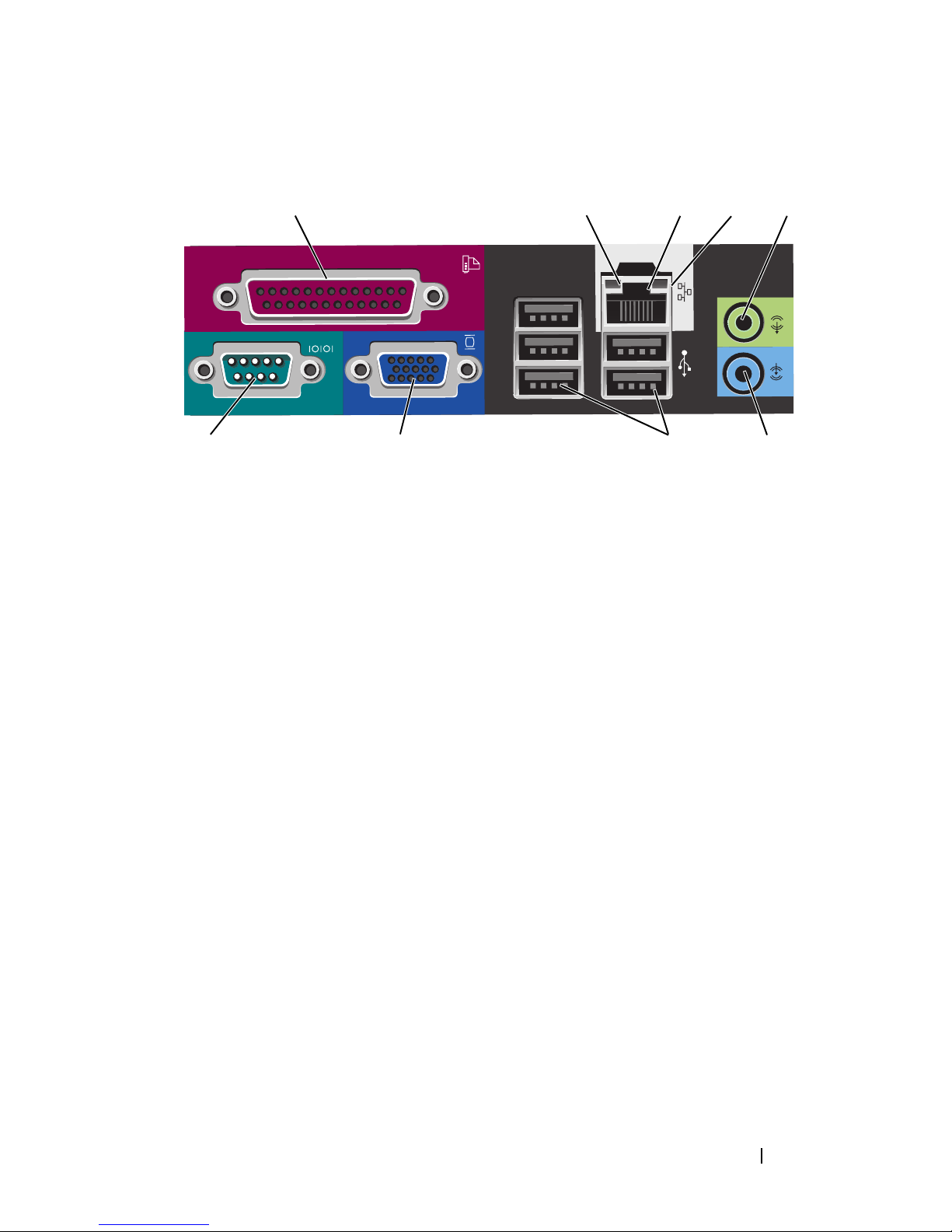
Mini Tower Computer — Back-Panel Connectors
13
98 7
1 parallel connector Connect a parallel device, such as a printer, to the parallel
connector. If you have a USB printer, plug it into a USB
connector.
24
5
6
NOTE: The integrated parallel connector is automatically
disabled if the computer detects an installed card containing a
parallel connector configured to the same address. For more
information, see "System Setup Program" in your online User’s
Guide for instructions.
2 link integrity light
• Green — A good connection exists between a 10-Mbps
network and the computer.
• Orange — A good connection exists between a 100-Mbps
network and the computer.
• Yellow — A good connection exists between a 1-Gbps
(or 1000-Mbps) network and the computer.
• Off — The computer is not detecting a physical
connection to the network.
Quick Reference Guide 19
Page 20

3 network adapter
connector
To attach your computer to a network or broadband device,
connect one end of a network cable to either a network jack
or your network or broadband device. Connect the other
end of the network cable to the network adapter connector
on the back panel of your computer. A click indicates that
the network cable has been securely attached.
NOTE: Do not plug a telephone cable into the network
connector.
On computers with a network connector card, use the
connector on the card.
It is recommended that you use Category 5 wiring and
connectors for your network. If you must use Category 3
wiring, force the network speed to 10 Mbps to ensure
reliable operation.
4 network activity
light
5 line-out
connector
6 line-in connector Use the line-in connector to attach a record/playback device
7 USB 2.0
connectors (5)
8 video connector Plug the cable from your VGA-compatible monitor into the
Flashes a yellow light when the computer is transmitting or
receiving network data. A high volume of network traffic
may make this light appear to be in a steady "on" state.
Use the green line-out connector to attach headphones and
most speakers with integrated amplifiers.
On computers with a sound card, use the connector on the
card.
such as a cassette player, CD player, or VCR.
On computers with a sound card, use the connector on the
card.
Use the back USB connectors for devices that typically
remain connected, such as printers and keyboards.
blue connector.
NOTE: If you purchased an optional graphics card, this
connector will be covered by a cap. Do not remove the cap.
Connect your monitor to the connector on the graphics card.
20 Quick Reference Guide
NOTE: If you are using a graphics card that supports dual
monitors, use the y-cable that came with your computer.
Page 21
9 serial connector Connect a serial device, such as a handheld device, to the
serial port. The default designations are COM1 for serial
connector 1 and COM2 for serial connector 2.
For more information, see "System Setup Program" in your
online User’s Guide.
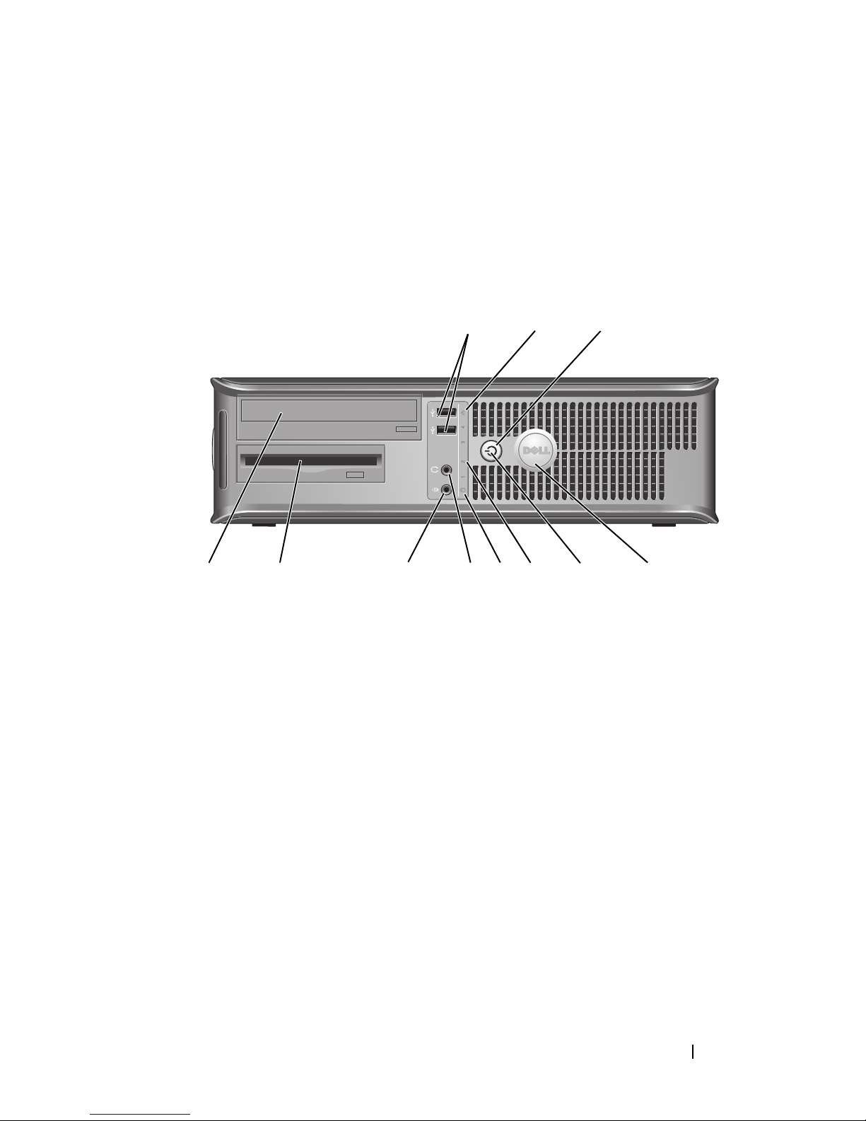
Desktop Computer — Front View
1 USB 2.0
connectors (2)
1
89
2
7
3
5
4611 10
Use the front USB connectors for devices that you connect
occasionally, such as joysticks or cameras, or for bootable
USB devices see "System Setup Program" in your online
User’s Guide for instructions for more information about
booting to a USB device).
It is recommended that you use the back USB connectors
for devices that typically remain connected, such as
printers and keyboards.
Quick Reference Guide 21
Page 22

2 LAN indicator
light
3 power button Press this button to turn on the computer.
4 Dell badge This badge can be rotated to match the orientation of your
5 power light The power light illuminates and blinks or remains solid to
This light indicates that a local area network (LAN)
connection is established.
NOTICE: To avoid losing data, do not turn off the
computer by pressing the power button. Instead,
perform an operating system shutdown. See "Turning
Off Your Computer" in your online User’s Guide for more
information.
NOTICE: If your operating system has ACPI enabled,
when you press the power button the computer will
perform an operating system shutdown.
computer. To rotate, place fingers around the outside of
the badge, press firmly, and turn the badge. You can also
rotate the badge using the slot provided near the bottom of
the badge.
indicate different operating states:
• No light — The computer is turned off.
• Steady green — The computer is in a normal operating
state.
• Blinking green — The computer is in a power-saving
mode.
ee
• Blinking or solid amber — S
online
To exit from a power-saving mode, press the power button
or use the keyboard or the mouse if it is configured as a
wake device in the Windows Device Manager. For more
information about sleep modes and exiting from a powersaving mode, see "Power Management" in your online
User’s Guide for instructions.
See "System Lights" on page 54 for a description of light
codes that can help you troubleshoot problems with your
computer.
6 diagnostic lights Use the lights to help you troubleshoot a computer
problem based on the diagnostic code. For more
information, see "Diagnostic Lights" on page 55.
User’s Guide
for instructions.
"Power Problems" in your
22 Quick Reference Guide
Page 23
7 hard-drive
activity light
This light flickers when the hard drive is being accessed.
8 headphone
connector
9 microphone
Use the headphone connector to attach headphones and
most kinds of speakers.
Use the microphone connector to attach a microphone.
connector
10 drive bay This bay accommodates an optional floppy drive, media
card reader, or second hard drive.
11 optical drive
Insert an optical drive (if supported) into this bay.
(optional)
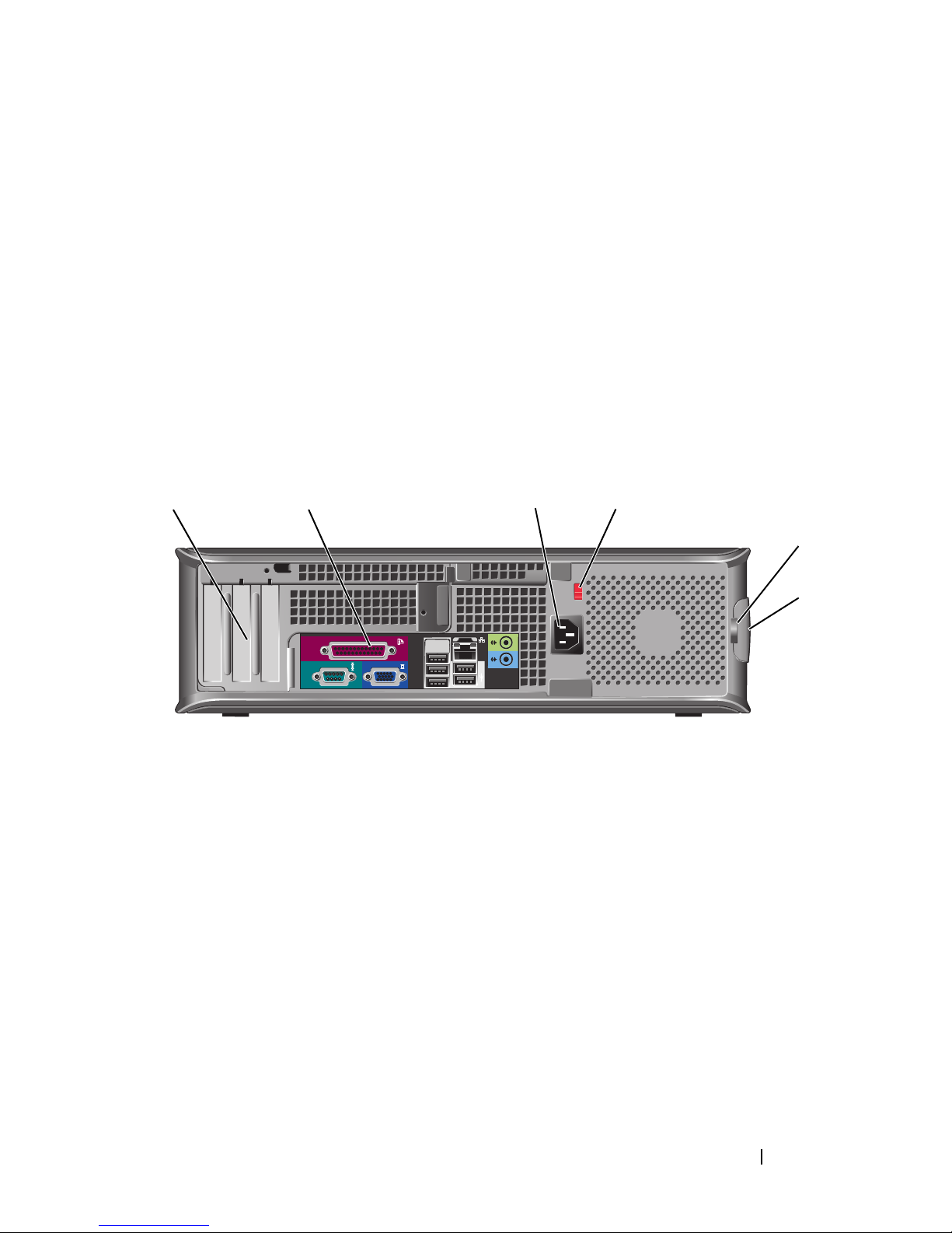
Desktop Computer — Back View
1 2 3 4
5
6
1 card slots (3) Access connectors for any installed PCI and PCI Express
cards.
2 back-panel
connectors
Plug serial, USB, and other devices into the appropriate
connectors (see "Desktop Computer — Back-Panel
Connectors" on page 24).
3 power connector Insert the power cable.
Quick Reference Guide 23
Page 24
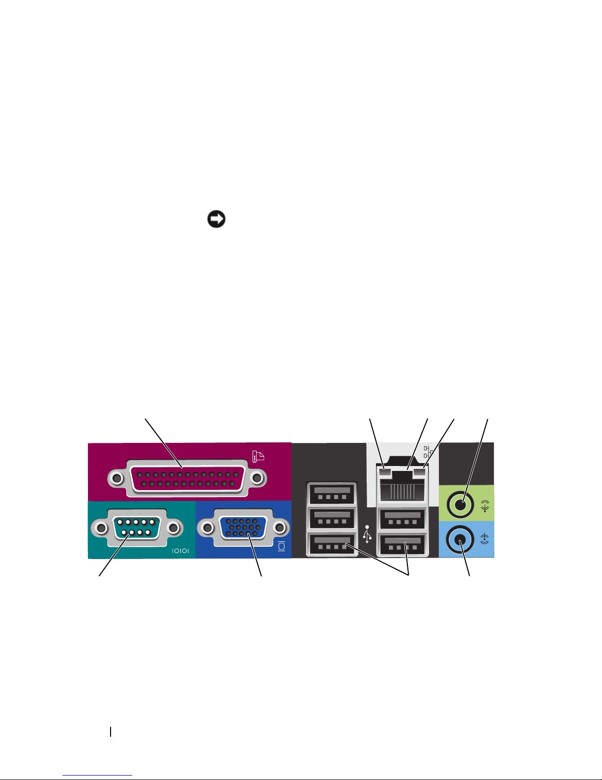
4 voltage selection
switch
5 padlock ring Insert a padlock to lock the computer cover.
NOTE: Your computer may or may not have a voltage selection
switch.
Your computer may equipped with a manual voltageselection switch.
To help avoid damaging a computer with a manual voltage
selection switch, set the switch for the voltage that most
closely matches the AC power available in your location.
NOTICE: In Japan, the voltage selection switch must be
set to the 115-V position even though the AC power
available in Japan is 100 V.
Also, ensure that your monitor and attached devices are
electrically rated to operate with the AC power available in
your location.
6 cover release
latch
Allows you to open the computer cover.
Desktop Computer — Back-Panel Connectors
13
987
24
5
6
24 Quick Reference Guide
Page 25

1 parallel
connector
Connect a parallel device, such as a printer, to the parallel
connector. If you have a USB printer, plug it into a USB
connector.
NOTE: The integrated parallel connector is automatically
disabled if the computer detects an installed card containing
a parallel connector configured to the same address. For
more information, see "System Setup Programs" in your online
User’s Guide.
2 link integrity
light
3 network adapter
connector
• Green — A good connection exists between a 10-Mbps
network and the computer.
• Orange — A good connection exists between a 100-Mbps
network and the computer.
• Yellow — A good connection exists between a 1-Gbps
(or 1000-Mbps) network and the computer.
• Off — The computer is not detecting a physical
connection to the network.
To attach your computer to a network or broadband device,
connect one end of a network cable to either a network jack
or your network or broadband device. Connect the other
end of the network cable to the network adapter connector
on the back panel of your computer. A click indicates that
the network cable has been securely attached.
NOTE: Do not plug a telephone cable into the network
connector.
On computers with a network connector card, use the
connector on the card.
4 network activity
light
5 line-out
connector
It is recommended that you use Category 5 wiring and
connectors for your network. If you must use Category 3
wiring, force the network speed to 10 Mbps to ensure
reliable operation.
Flashes a yellow light when the computer is transmitting or
receiving network data. A high volume of network traffic
may make this light appear to be in a steady "on" state.
Use the green line-out connector to attach headphones and
most speakers with integrated amplifiers.
On computers with a sound card, use the connector on the
card.
Quick Reference Guide 25
Page 26

6 line-in connector Use the line-in connector to attach a record/playback device
such as a cassette player, CD player, or VCR.
On computers with a sound card, use the connector on the
card.
7 USB 2.0
connectors (5)
8 video connector Plug the cable from your VGA-compatible monitor into the
Use the back USB connectors for devices that typically
remain connected, such as printers and keyboards.
blue connector.
NOTE: If you purchased an optional graphics card, this
connector will be covered by a cap. Do not remove the cap.
Connect your monitor to the connector on the graphics card.
NOTE: If you are using a graphics card that supports dual
monitors, use the y-cable that came with your computer.
9 serial connector Connect a serial device, such as a handheld device, to the
serial port. The default designations are COM1 for serial
connector 1 and COM2 for serial connector 2.
NOTE: There is only a serial connector 2 if the optional
PS2/serial adapter is used.
For more information, see "System Setup Program" in your
online User’s Guide.
Small Form Factor Computer — Front View
11 10
26 Quick Reference Guide
1
89
7
2
3
4
5
6
Page 27

1 USB 2.0
connectors (2)
Use the front USB connectors for devices that you connect
occasionally, such as joysticks or cameras, or for bootable
USB devices (see "System Setup Program" in your online
User’s Guide for instructions about booting to a USB
device).
It is recommended that you use the back USB connectors
for devices that typically remain connected, such as printers
and keyboards.
2 power button Press to turn on the computer.
NOTICE: To avoid losing data, do not turn off the
computer by pressing the power button. Instead,
perform an operating system shutdown. See "Turning Off
Your Computer" in your online User’s Guide for
instructions for more information.
NOTICE: If your operating system has ACPI enabled,
when you press the power button the computer will
perform an operating system shutdown.
3 Dell badge This badge can be rotated to match the orientation of your
computer. To rotate, place fingers around the outside of the
badge, press firmly, and turn the badge. You can also rotate
the badge using the slot provided near the bottom of the
badge.
4 hard drive
This light flickers when the hard drive is being accessed.
activity light
5 diagnostic lights Use the lights to help you troubleshoot a computer problem
based on the diagnostic code. For more information, see
"Diagnostic Lights" on page 55.
6 LAN indicator
light
This light indicates that a LAN (local area network)
connection is established.
Quick Reference Guide 27
Page 28

7 power light The power light illuminates and blinks or remains solid to
indicate different operating states:
• No light — The computer is turned off.
• Steady green — The computer is in a normal operating
state.
• Blinking green — The computer is in a power-saving
mode.
8 headphone
connector
9 microphone
connector
10 floppy drive bay
(optional)
11 optical drive
(optional)
• Blinking or solid amber —
See "Power Problems" in your
online User’s Guide.
To exit from a power-saving mode, press the power button
or use the keyboard or the mouse if it is configured as a
wake device in the Windows Device Manager. For more
information about sleep modes and exiting from a powersaving mode, see "Power Management" in your online User’s
Guide.
See "System Lights" on page 54 for a description of light
codes that can help you troubleshoot problems with your
computer.
Use the headphone connector to attach headphones and
most kinds of speakers.
Use the microphone connector to attach a microphone.
Can contain an optional slimline floppy drive or optional
slimline media card reader.
Insert slimline optical drive (if supported) into this bay.
28 Quick Reference Guide
Page 29

Small Form Factor Computer — Back View
1 card slots (2) Access connectors for any installed PCI and PCI Express
cards.
51 2 3 4
6
2 back-panel
connectors
3 power connector Insert the power cable.
4 voltage selection
switch
5 padlock ring Insert a padlock to lock the computer cover.
6 cover release
latch
Plug serial, USB, and other devices into the appropriate
connectors (see "Small Form Factor Computer — BackPanel Connectors" on page 30).
Your computer may be equipped with a manual voltageselection switch. To help avoid damaging a computer with a
manual voltage selection switch, set the switch for the
voltage that most closely matches the AC power available in
your location.
NOTICE: In Japan, the voltage selection switch must be
set to the 115-V position even though the AC power
available in Japan is 100 V.
Also, ensure that your monitor and attached devices are
electrically rated to operate with the AC power available in
your location.
Allows you to open the computer cover.
Quick Reference Guide 29
Page 30
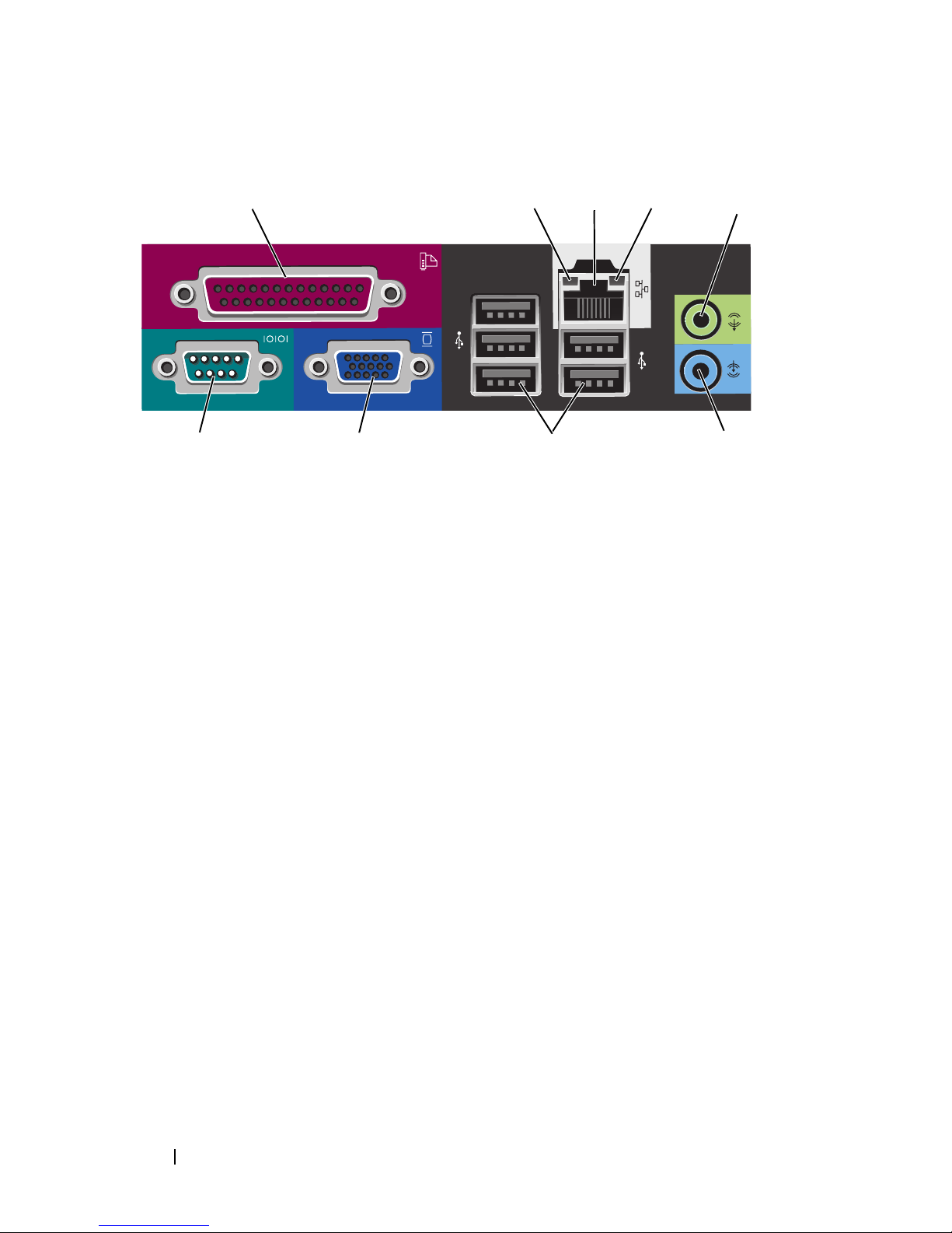
Small Form Factor Computer — Back-Panel Connectors
98 7
1 parallel
connector
13
Connect a parallel device, such as a printer, to the parallel
connector. If you have a USB printer, plug it into a USB
connector.
24
5
6
NOTE: The integrated parallel connector is automatically disabled
if the computer detects an installed card containing a parallel
connector configured to the same address. For more information,
see "System Setup Program" in your online User’s Guide.
2 link integrity
light
• Green — A good connection exists between a 10-Mbps network
and the computer.
• Orange — A good connection exists between a 100-Mbps
network and the computer.
• Yellow — A good connection exists between a 1-Gbps
(or 1000-Mbps) network and the computer.
• Off — The computer is not detecting a physical connection to
the network.
30 Quick Reference Guide
Page 31

3 network
adapter
connector
To attach your computer to a network or broadband device,
connect one end of a network cable to either a network jack or
your network or broadband device. Connect the other end of the
network cable to the network adapter connector on the back
panel of your computer. A click indicates that the network cable
has been securely attached.
NOTE: Do not plug a telephone cable into the network connector.
On computers with a network connector card, use the connector
on the card.
It is recommended that you use Category 5 wiring and
connectors for your network. If you must use Category 3 wiring,
force the network speed to 10 Mbps to ensure reliable operation.
4 network
activity light
5 line-out
connector
6 line-in
connector
7 USB 2.0
connectors
(5)
8 video
connector
Flashes a yellow light when the computer is transmitting or
receiving network data. A high volume of network traffic may
make this light appear to be in a steady "on" state.
Use the green line-out connector to attach headphones and
most speakers with integrated amplifiers.
On computers with a sound card, use the connector on the card.
Use the line-in connector to attach a record/playback device
such as a cassette player, CD player, or VCR.
On computers with a sound card, use the connector on the card.
Use the back USB connectors for devices that typically remain
connected, such as printers and keyboards.
Plug the cable from your VGA-compatible monitor into the blue
connector.
NOTE: If you purchased an optional graphics card, this connector
will be covered by a cap. Do not remove the cap. Connect your
monitor to the connector on the graphics card.
NOTE: If you are using a graphics card that supports dual
monitors, use the y-cable that came with your computer.
Quick Reference Guide 31
Page 32

9 serial
connector
Connect a serial device, such as a handheld device, to the serial
port. The default designations are COM1 for serial connector 1
and COM2 for serial connector 2.
NOTE: There is only a serial connector 2 if the optional PS2/serial
adapter is used.
For more information, see "System Setup Program" in your
online User’s Guide for instructions.
Removing the Computer Cover
CAUTION: Before you begin any of the procedures in this section, follow the
safety instructions in the Product Information Guide.
CAUTION: To guard against electrical shock, always unplug your computer from
the electrical outlet before removing the cover.
Before You Begin
NOTICE: To avoid losing data, save and close any open files and exit any open
programs before you turn off your computer.
1
Shut down the operating system:
a
Save and close any open files, exit any open programs, click the
button, and then click
b
In the
Shut Down
drop-menu, and then click
window, select the
Shut Down
OK
.
.
Shut Down
option from the
The computer turns off after the operating system shutdown process
finishes.
2
Ensure that the computer and any attached devices are turned off. If your
computer and attached devices did not automatically turn off when you
shut down your operating system, turn them off now.
Before Working Inside Your Computer
Use the following safety guidelines to help protect your computer from
potential damage and to help ensure your own personal safety.
CAUTION: Before you begin any of the procedures in this section, follow the
safety instructions in the Product Information Guide.
Start
32 Quick Reference Guide
Page 33

CAUTION: Handle components and cards with care. Do not touch the components
or contacts on a card. Hold a card by its edges or by its metal mounting bracket.
Hold a component such as a processor by its edges, not by its pins.
NOTICE: Only a certified service technician should perform repairs on your
computer. Damage due to servicing that is not authorized by Dell is not covered by
your warranty.
NOTICE: When you disconnect a cable, pull on its connector or on its strain-relief
loop, not on the cable itself. Some cables have a connector with locking tabs; if you
are disconnecting this type of cable, press in on the locking tabs before you
disconnect the cable. As you pull connectors apart, keep them evenly aligned to
avoid bending any connector pins. Also, before you connect a cable, ensure that
both connectors are correctly oriented and aligned.
To avoid damaging the computer, perform the following steps before you
begin working inside the computer.
1
Turn off your computer.
NOTICE: To disconnect a network cable, first unplug the cable from your computer
and then unplug it from the network wall jack.
2
Disconnect any telephone or telecommunication lines from the computer.
3
Disconnect your computer and all attached devices from their electrical
outlets, and then press the power button to ground the system board.
4
If applicable, remove the computer stand (for instructions, see the
documentation that came with the stand).
CAUTION: To guard against electrical shock, always unplug your computer from
the electrical outlet before removing the cover.
5
Remove the computer cover:
• Remove the mini tower computer cover (see "Mini Tower Computer"
on page 34).
• Remove the desktop computer cover (see "Desktop Computer" on
page 36).
• Remove the small form factor computer cover (see "Small Form
Factor Computer" on page 38).
NOTICE: Before touching anything inside your computer, ground yourself by
touching an unpainted metal surface, such as the metal at the back of the computer.
While you work, periodically touch an unpainted metal surface to dissipate any
static electricity that could harm internal components.
Quick Reference Guide 33
Page 34

Mini Tower Computer
CAUTION: Before you begin any of the procedures in this section, follow the
safety instructions in the Product Information Guide.
CAUTION: To guard against electrical shock, always unplug your computer from
the electrical outlet before removing the computer cover.
1
Follow the procedures in "Before You Begin" on page 32.
2
If you have installed a padlock through the padlock ring on the back panel,
remove the padlock.
3
Lay the computer on its side.
4
Slide the cover release latch back as you lift the cover.
5
Grip the sides of the computer cover and pivot the cover up using the
hinge tabs as leverage points.
6
Remove the cover from the hinge tabs and set it aside on a soft
nonabrasive surface.
34 Quick Reference Guide
Page 35
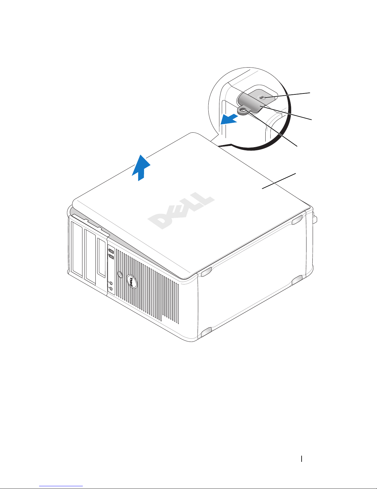
1
2
3
4
1 security cable slot 2 cover release latch 3 padlock ring
4 computer cover
Quick Reference Guide 35
Page 36

Desktop Computer
CAUTION: Before you begin any of the procedures in this section, follow the
safety instructions in the Product Information Guide.
CAUTION: To guard against electrical shock, always unplug your computer from
the electrical outlet before removing the computer cover.
1
Follow the procedures in "Before You Begin" on page 32.
2
If you have installed a padlock through the padlock ring on the back panel,
remove the padlock.
3
Lay the computer on its side.
4
Slide the cover release latch back as you lift the cover.
5
Grip the sides of the computer cover and pivot the cover up using the
hinge tabs as leverage points.
6
Remove the cover from the hinge tabs and set it aside on a soft
nonabrasive surface.
36 Quick Reference Guide
Page 37
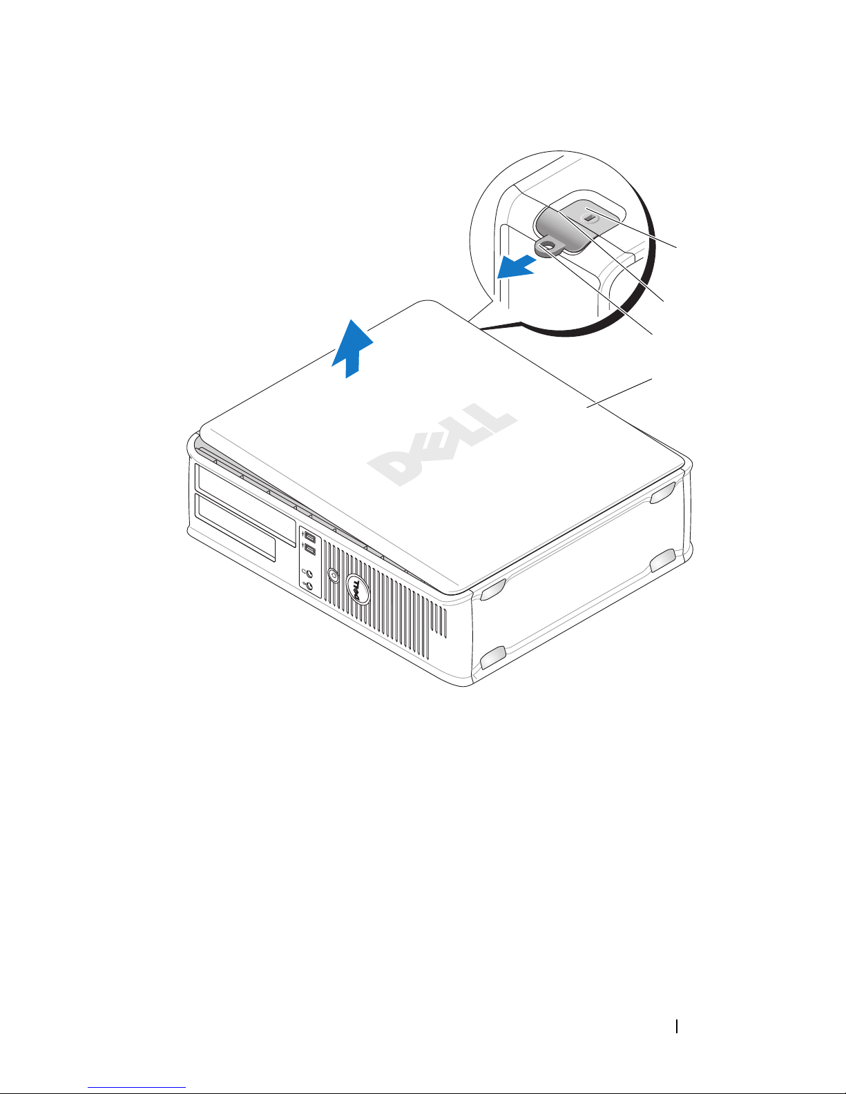
1
2
3
4
1 security cable slot 2 cover release latch 3 padlock ring
4 computer cover
Quick Reference Guide 37
Page 38

Small Form Factor Computer
CAUTION: Before you begin any of the procedures in this section, follow the
safety instructions in the Product Information Guide.
CAUTION: To guard against electrical shock, always unplug your computer from
the electrical outlet before removing the computer cover.
1
Follow the procedures in "Before You Begin" on page 32.
2
If you have installed a padlock through the padlock ring on the back panel,
remove the padlock.
3
Lay the computer on its side.
4
Slide the release latch back as you lift the cover.
5
Grip the sides of the computer cover and pivot the cover up using the
bottom hinges as leverage points.
6
Remove the cover from the hinge tabs and set it aside on a soft
nonabrasive surface.
CAUTION: Graphic card heat sinks can become very hot during normal operation.
Ensure that a graphic card heat sink has had sufficient time to cool before you
touch it.
38 Quick Reference Guide
Page 39

1
2
3
4
1 security cable slot 2 cover release latch 3 padlock ring
4 computer cover
Inside Your Computer
Mini Tower Computer
CAUTION: Before you begin any of the procedures in this section, follow the
safety instructions in the Product Information Guide.
CAUTION: To avoid electrical shock, always unplug your computer from the
electrical outlet before removing the computer cover.
Quick Reference Guide 39
Page 40
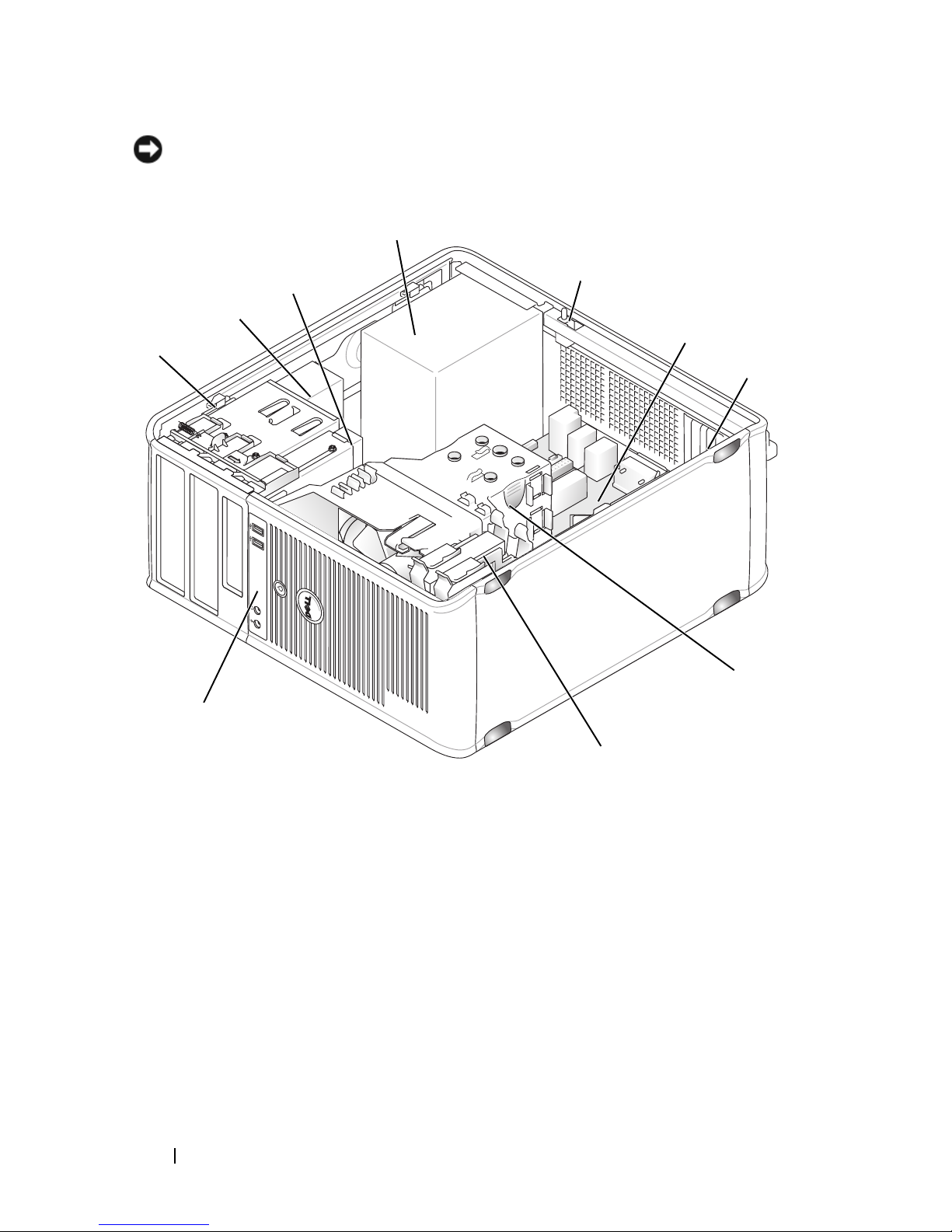
NOTICE: Be careful when opening the computer cover to ensure that you do not
accidentally disconnect cables from the system board.
4
3
5
2
6
1
7
8
10
9
1 drive release latch 2 optical drive 3 floppy drive
4 power supply 5 chassis intrusion
6 system board
switch (optional)
7 card slots (4) 8 heat sink assembly 9 hard drive
10 front I/O panel
40 Quick Reference Guide
Page 41
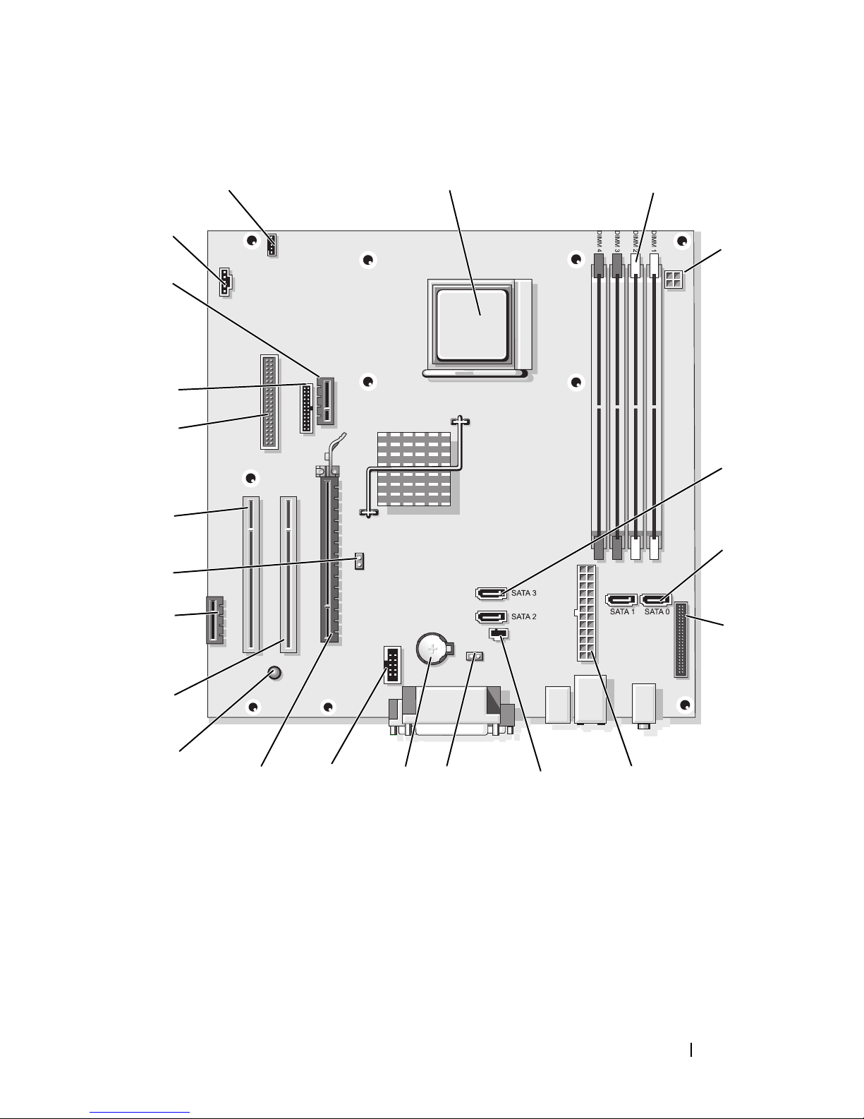
System Board Components
22
21
20
19
18
17
1
2
3
4
5
6
16
15
14
13 12 10
1 speaker connector
(INT_SPKR)
4 power connector
(PW_12V_A1)
11
2 processor socket
(CPU)
5 SATA drive
connectors (SATA2,
SATA3)
9
8
3 memory module
connectors
(DIMM_1, DIMM_2,
DIMM_3, DIMM_4)
6 SATA drive
connectors (SATA0,
SATA1)
7
Quick Reference Guide 41
Page 42
7 front-panel
connector
(FRONTPANEL)
8 power connector
(POWER1)
9 intrusion switch
connector
(INTRUDER)
10 CMOS reset jumper
(RTCRST)
13 PCI Express x16
connector (SLOT1)
16 PCI Express x1
connector (SLOT4)
19 floppy drive
connector (DSKT)
22 fan connector
(FAN_CPU)
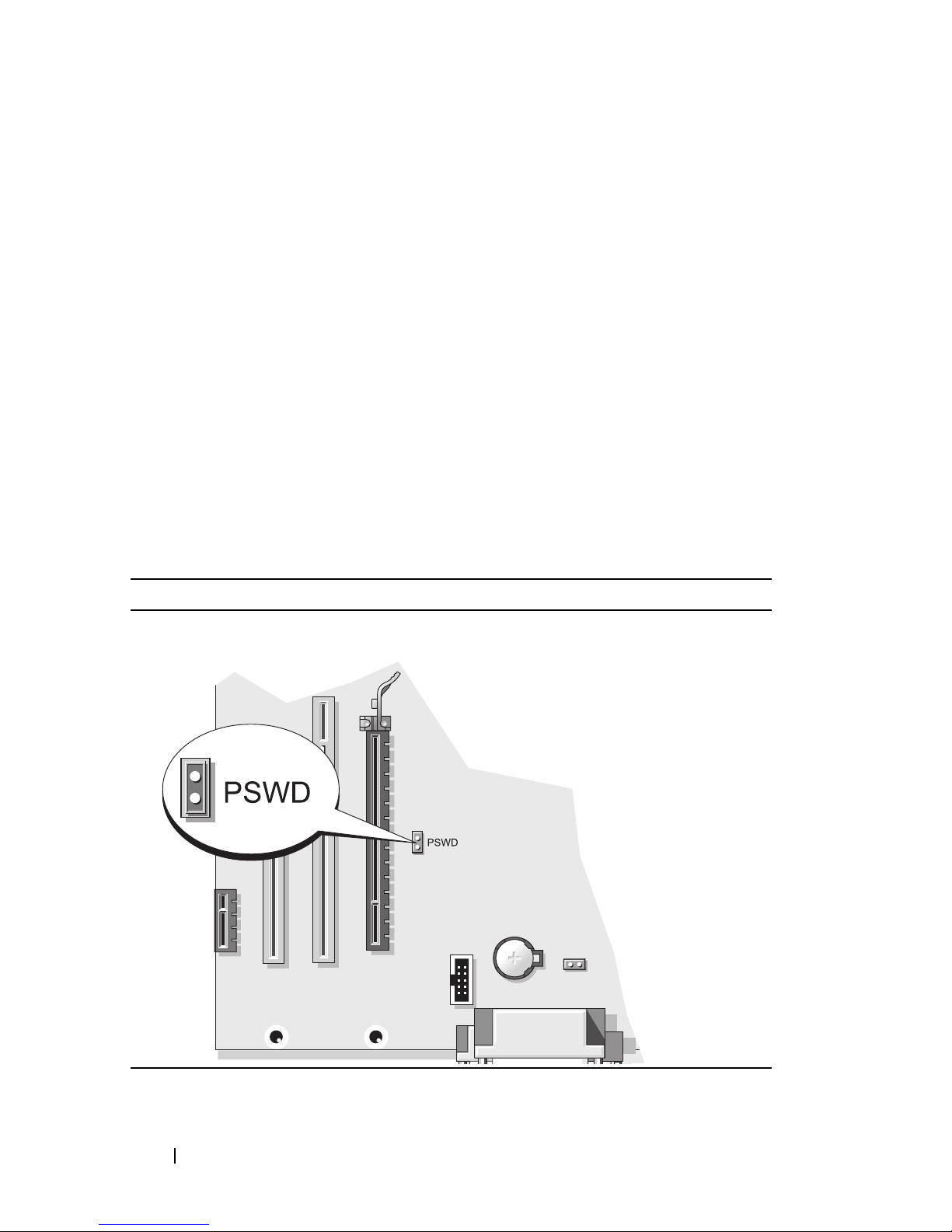
Jumper Settings
Mini Tower Computer
11 battery socket
(BATTERY)
14 standby power
(AUX_PWR_LED)
17 password jumper
(PSWD)
20 serial connector
(PS2/SER2)
12 internal USB (USB1)
15 PCI connector
(SLOT2)
18 PCI connector
(SLOT3)
21 optional DVI-card
connector
(DVI_HDR)
42 Quick Reference Guide
Page 43
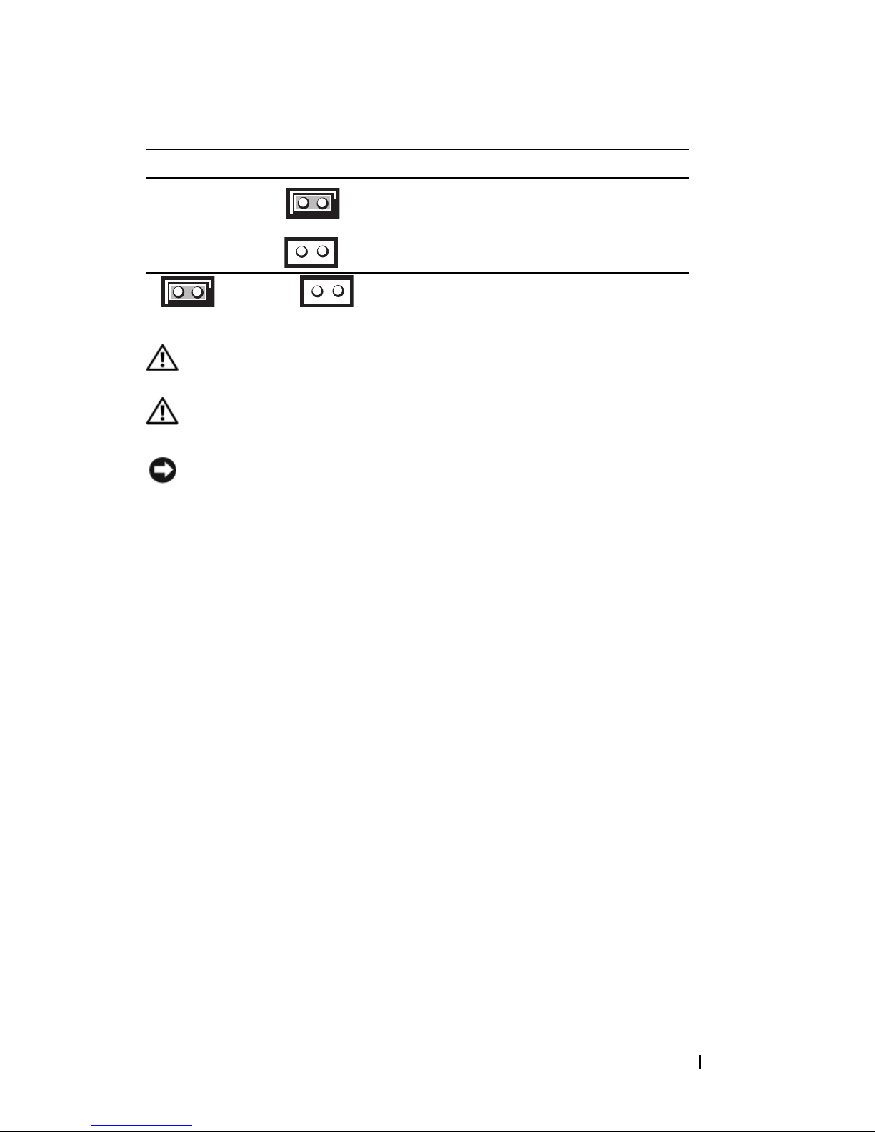
Jumper Setting Description
PSWD Password features are enabled
(default setting).
Password features are disabled.
jumpered unjumpered
Desktop Computer
CAUTION: Before you begin any of the procedures in this section, follow the
safety instructions in the Product Information Guide.
CAUTION: To avoid electrical shock, always unplug your computer from the
electrical outlet before removing the computer cover.
NOTICE: Be careful when opening the computer cover to ensure that you do not
accidentally disconnect cables from the system board.
Quick Reference Guide 43
Page 44
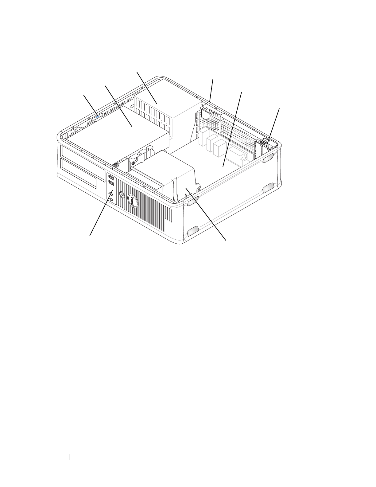
3
4
2
1
5
6
8
7
1 drive release latch 2 optical drive 3 power supply
4 chassis intrusion
5 system board 6 card slots (3)
switch (optional)
7 heat sink assembly 8 front I/O panel
44 Quick Reference Guide
Page 45
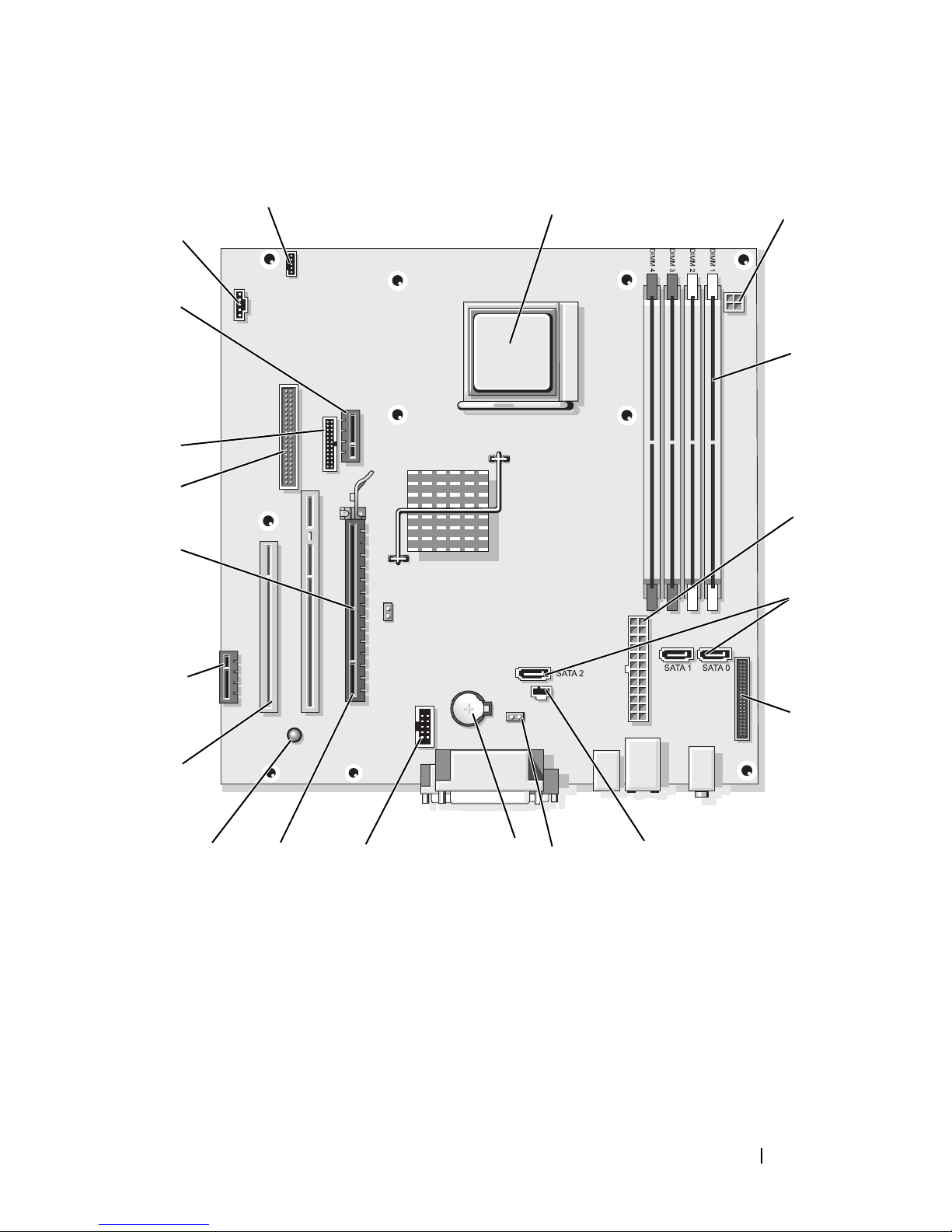
System Board Components
20
19
18
17
16
1
2
3
4
5
6
15
14
13
12
1 speaker connector
(INT_SPKR)
4 memory module
connectors
(DIMM_1, DIMM_2,
DIMM_3, DIMM_4)
10
2 processor socket
(CPU)
5 power connector
(POWER1)
7
8911
3 power connector
(PW_12V_A1)
6 SATA drive
connectors (SATA0,
SATA1, SATA2)
Quick Reference Guide 45
Page 46
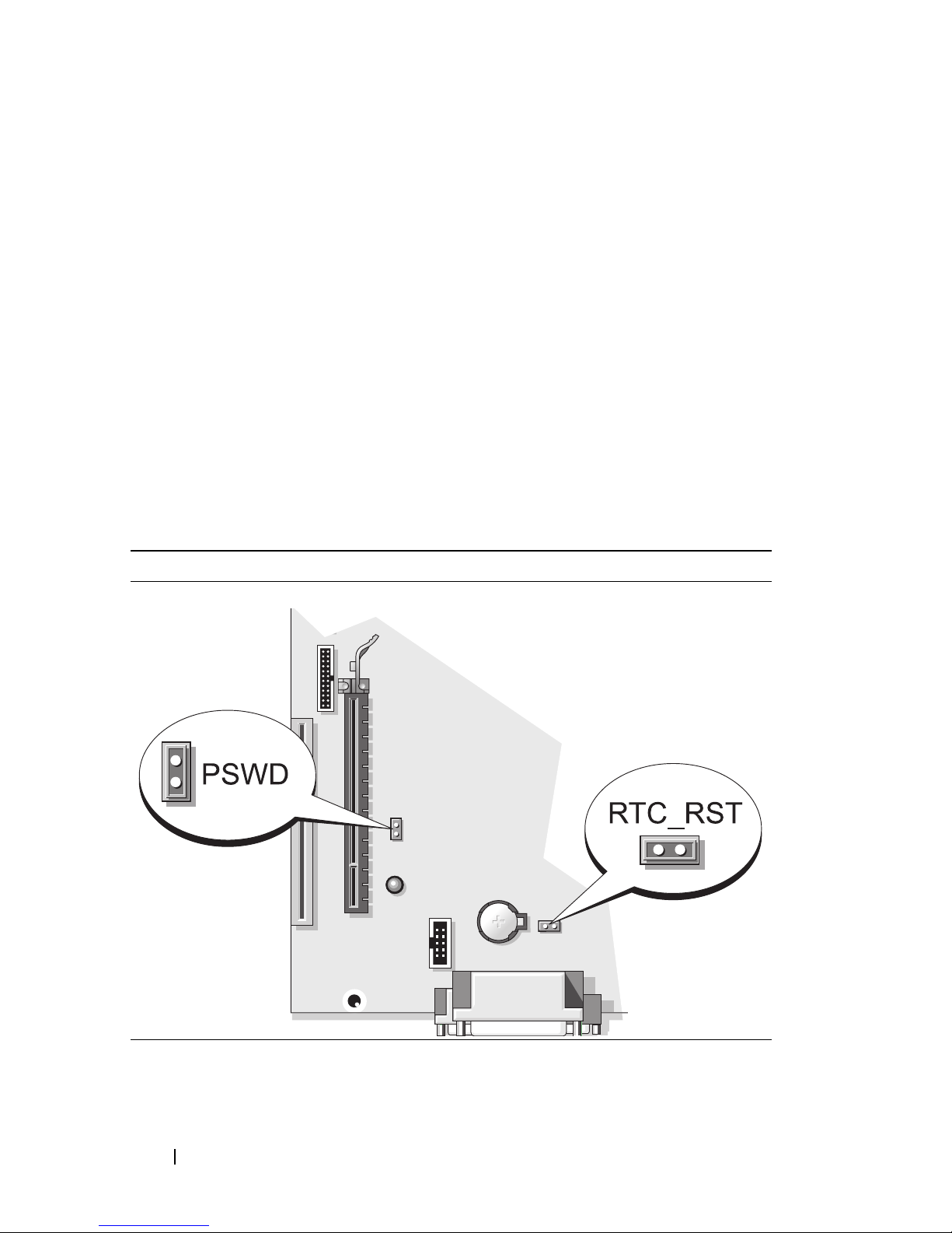
7 front-panel connector
(FRONTPANEL)
8 intrusion switch
connector
(INTRUDER)
9 CMOS reset jumper
(RTCRST)
10 battery socket
(BATTERY)
13 standby power
(AUX_PWR_LED)
16 password jumper
(PSWD)
19 optional DVI-card
connector
(DVI_HDR)
Jumper Settings
Desktop Computer
11 internal USB
(USB1)
14 PCI connectors
(SLOT2, SLOT3)
17 floppy drive
connector (DSKT)
20 fan connector
(FAN_CPU)
12 PCI Express x16
connector (SLOT1)
15 PCI Express
x1connector (SLOT4)
18 serial connector
(PS2/SER2)
46 Quick Reference Guide
Page 47
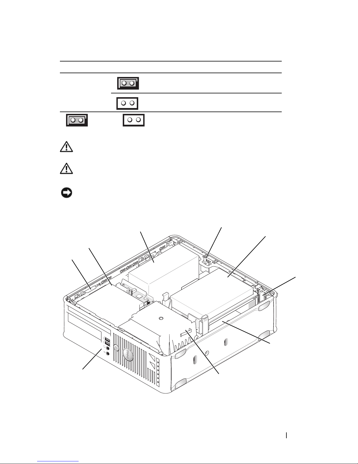
Jumper Setting Description
PSWD Password features are enabled
(default setting).
Password features are disabled.
jumpered unjumpered
Small Form Factor Computer
CAUTION: Before you begin any of the procedures in this section, follow the
safety instructions in the Product Information Guide.
CAUTION: To avoid electrical shock, always unplug your computer from the
electrical outlet before removing the computer cover.
NOTICE: Be careful when opening the computer cover to ensure that you do not
accidentally disconnect cables from the system board.
3
2
1
9
4
5
6
7
8
Quick Reference Guide 47
Page 48
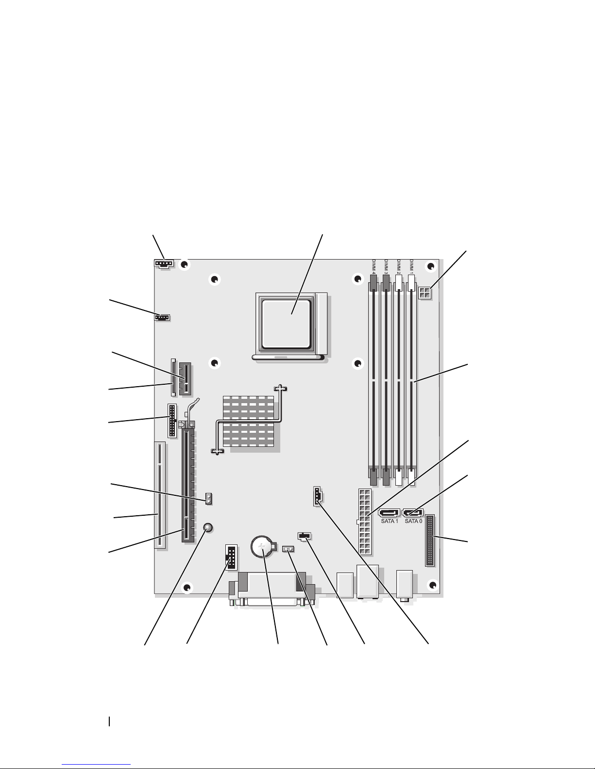
1 drive release latch 2 optical drive 3 power supply
4 chassis intrusion
5 hard drive 6 card slots (2)
switch (optional)
7 system board 8 heat sink assembly 9 front I/O panel
System Board Components
12
20
19
18
3
4
17
16
15
14
13
10
5
6
7
91112
8
48 Quick Reference Guide
Page 49

1 fan connector
(FAN_CPU)
2 processor socket
(CPU)
3 power connector
(PW_12V_A1)
4 memory module
connectors
(DIMM_1,
DIMM_2, DIMM_3,
DIMM_4)
7 front-panel
connector
(FRONTPANEL)
10 CMOS reset jumper
(RTCRST)
13 standby
(AUX_PWR_LED)
16 password jumper
(PSWD)
19 optional DVI-card
connector
(DVI_HDR)
5 power connector
(POWER1)
8 fan connector
(FAN_HDD)
11 battery socket
(BATTERY)
14 PCI Express x16
connector (SLOT1)
17 serial connector
(PS2/SER2)
20 speaker connector
(INT_SPKR)
6 SATA drive
connectors (SATA0,
SATA1)
9 intrusion switch
connector
(INTRUDER)
12 internal USB (USB1)
15 PCI connector
(SLOT2)
18 slimline floppy-drive
connector (DSKT)
Quick Reference Guide 49
Page 50
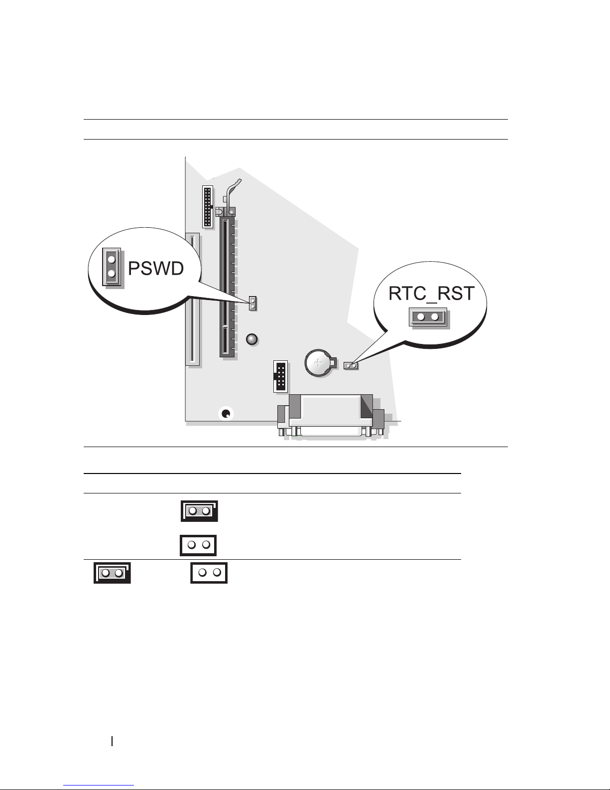
Jumper Settings
Small Form Factor Computer
Jumper Setting Description
PSWD Password features are enabled
(default setting).
Password features are disabled.
jumpered unjumpered
Solving Problems
Dell provides a number of tools to help you if your computer does not
perform as expected. For the latest troubleshooting information available for
your computer, see the Dell Support website at support.dell.com.
50 Quick Reference Guide
Page 51

If computer problems occur that require help from Dell, write a detailed
description of the error, beep codes, or diagnostics light patterns, record your
Express Service Code and Service Tag below, and then contact Dell from the
same location as your computer. For information on contacting Dell, see your
online User’s Guide.
For an example of the Express Service Code and Service Tag, see "Finding
Information" on page 5.
Express Service Code:___________________________
Service Tag:___________________________
Dell Diagnostics
CAUTION: Before you begin any of the procedures in this section, follow the
safety instructions in the Product Information Guide.
When to Use the Dell Diagnostics
If you experience a problem with your computer, perform the checks in
"Solving Problems" in your online User’s Guide and run the Dell Diagnostics
before you contact Dell for technical assistance. For information on
contacting Dell, see your online User’s Guide.
NOTICE: The Dell Diagnostics works only on Dell™ computers.
Enter system setup (see "System Setup Program" in your online User’s Guide
for instructions), review your computer’s configuration information, and
ensure that the device you want to test displays in system setup and is active.
Start the Dell Diagnostics from either your hard drive or from the optional
Drivers and Utilities media.
Starting the Dell Diagnostics From Your Hard Drive
The Dell Diagnostics is located on a hidden diagnostic utility partition on
your hard drive.
NOTE: If your computer cannot display a screen image, contact Dell (see your
online User’s Guide).
1
Shut down the computer. Turn on (or restart) your computer.
2
When the DELL™ logo appears, press <F12> immediately.
Quick Reference Guide 51
Page 52

NOTE: If you see a message stating that no diagnostics utility partition has been
found, run the Dell Diagnostics from your Drivers and Utilities media (optional).
If you wait too long and the operating system logo appears, continue to
®
wait until you see the Microsoft
Windows® desktop. Then shut down
your computer and try again.
3
When the boot device list appears, highlight
Boot to Utility Partition
press <Enter>.
4
When the Dell Diagnostics
Main Menu
appears, select the test you want
to run.
Starting the Dell Diagnostics From the Drivers and Utilities Media
1
Insert the
2
Shut down and restart the computer.
Drivers and Utilities
media.
When the DELL logo appears, press <F12> immediately.
If you wait too long and the operating system logo appears, continue to
wait until you see the Microsoft Windows desktop. Then shut down your
computer and try again.
and
NOTE: The next steps change the boot sequence for one time only. On the next
start-up, the computer boots according to the devices specified in the system setup
program.
3
When the boot device list appears, highlight the listing for the optical
drive and press <Enter>.
4
Select the listing for the optical drive option from the CD boot menu.
5
Select the option to boot from the optical drive from the menu that
appears.
6
Ty p e 1 to start the
7
Ty p e 2 to start the Dell Diagnostics.
8
Select
Run the 32 Bit Dell Diagnostics
Drivers and Utilities
media menu.
from the numbered list. If
multiple versions are listed, select the version appropriate for your
computer.
9
When the Dell Diagnostics
Main Menu
appears, select the test you want
to run.
52 Quick Reference Guide
Page 53
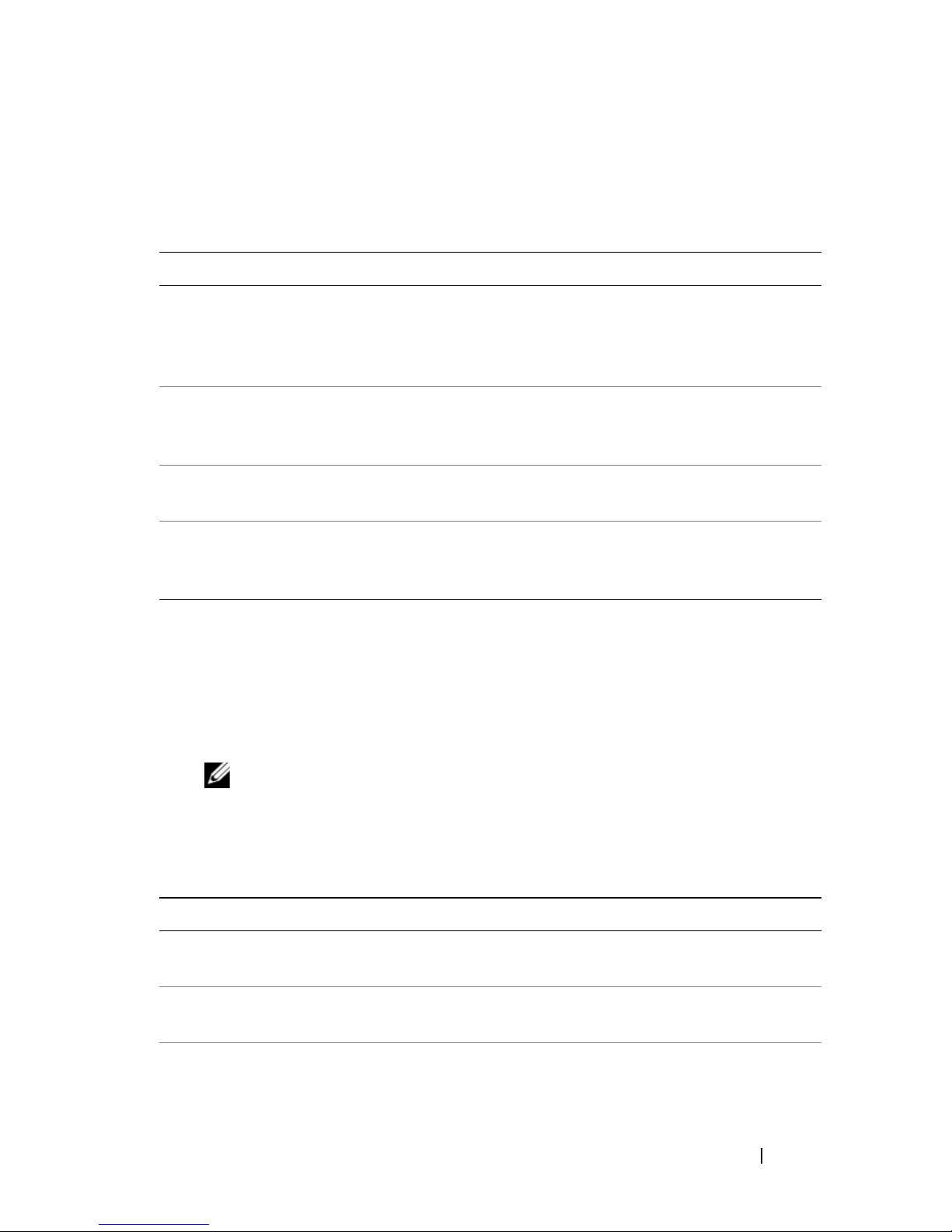
Dell Diagnostics Main Menu
1
After the Dell Diagnostics loads and the
Main Menu
screen appears, click
the button for the option you want.
Option Function
Express Test Performs a quick test of devices. This test typically takes 10 to
20 minutes and requires no interaction on your part. Run
Express Test first to increase the possibility of tracing the
problem quickly.
Extended Test Performs a thorough check of devices. This test typically takes
an hour or more and requires you to answer questions
periodically.
Custom Test Tests a specific device. You can customize the tests you want to
run.
Symptom Tree Lists the most common symptoms encountered and allows you
to select a test based on the symptom of the problem you are
having.
2
If a problem is encountered during a test, a message appears with an error
code and a description of the problem. Write down the error code and
problem description and follow the instructions on the screen.
If you cannot resolve the error condition, contact Dell. For information on
contacting Dell, see your online
NOTE: The Service Tag for your computer is located at the top of each test
screen. If you contact Dell, technical support will ask for your Service Tag.
3
If you run a test from the
Custom Test
User’s Guide
or
Symptom Tree
.
option, click the
applicable tab described in the following table for more information.
Tab Function
Results Displays the results of the test and any error conditions
encountered.
Errors Displays error conditions encountered, error codes, and the
problem description.
Help Describes the test and may indicate requirements for running the
test.
Quick Reference Guide 53
Page 54

Tab Function (continued)
Configuration Displays your hardware configuration for the selected device.
The Dell Diagnostics obtains configuration information for all
devices from system setup, memory, and various internal tests,
and it displays the information in the device list in the left pane
of the screen. The device list may not display the names of all the
components installed on your computer or all devices attached to
your computer.
Parameters You can customize the test by changing the test settings.
4
When the tests are completed, if you are running the Dell Diagnostics
from the
5
Close the test screen to return to the
Diagnostics and restart the computer, close the
Drivers and Utilities
media (optional), remove the CD or DVD.
Main Menu
screen. To exit the Dell
Main Menu
screen.
System Lights
Your power light may indicate a computer problem.
Power Light Problem Description Suggested Resolution
Solid green Power is on, and the
computer is operating
normally.
Blinking green The computer is in a
power-saving mode.
Blinks green
several times and
then turns off
A configuration error exists. See "Diagnostic Lights" on page 55
No corrective action is required.
Press the power button, move the
mouse, or press a key on the
keyboard to wake the computer.
to see if the specific problem is
identified.
54 Quick Reference Guide
Page 55

Power Light Problem Description Suggested Resolution
Solid yellow The Dell Diagnostics is
running a test, or a device
on the system board may be
faulty or incorrectly
installed.
Blinking yellow A power supply or system
board failure has occurred.
Solid green and a
beep code during
POST
A problem was detected
while the BIOS was
executing.
If the Dell Diagnostics is running,
allow the testing to complete.
See "Diagnostic Lights" on page 55
to see if the specific problem is
identified.
If the computer does not boot,
contact Dell for technical assistance.
For information on contacting Dell,
see your online
See "Diagnostic Lights" on page 55
to see if the specific problem is
identified.
See "Power Problems" in your online
User’s Guide.
For instructions on diagnosing the
beep code, see "Beep Codes" on
page 59. Also, see "Diagnostic
Lights" on page 55 to see if the
specific problem is identified.
User’s Guide
.
Solid green
power light, no
beep code and
no video during
POST
Solid green
power light and
no beep code,
but the
computer locks
up during POST
The monitor or the graphics
card may be faulty or
incorrectly installed.
An integrated system board
device may be faulty.
See "Diagnostic Lights" on page 55
to see if the specific problem is
identified.
See "Diagnostic Lights" on page 55
to see if the specific problem is
identified. If the problem is not
identified, contact Dell for technical
assistance.
contacting Dell, see your online
User’s Guide
For information on
.
Diagnostic Lights
CAUTION: Before you begin any of the procedures in this section, follow the
safety instructions located in the Product Information Guide.
Quick Reference Guide 55
Page 56
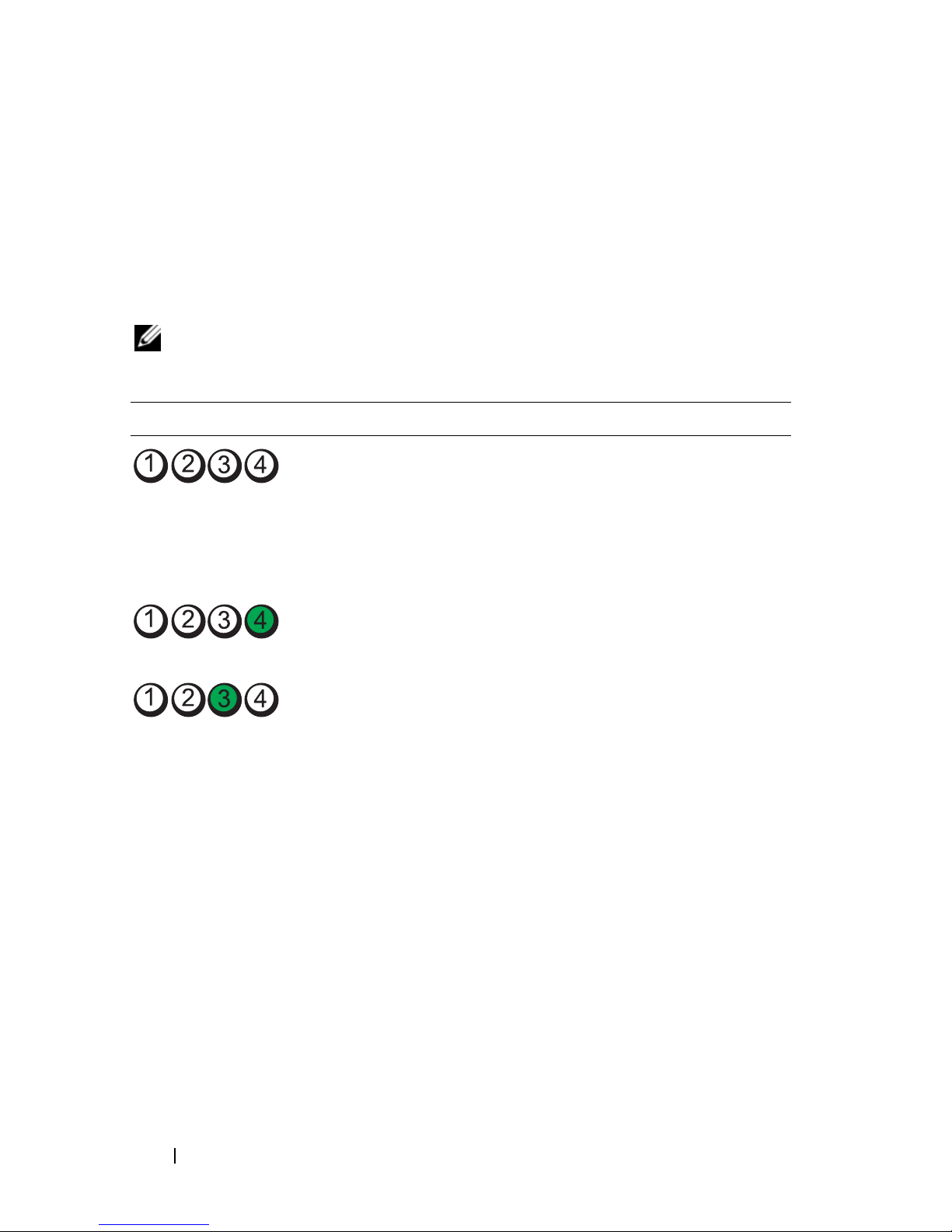
To help you troubleshoot a problem, your computer has four lights labeled
"1," "2," "3," and "4" on the front panel. The lights can be off or green. When
the computer starts normally, the patterns or codes on the lights change as
the boot process completes. If the POST portion of system boot completes
successfully, all four lights display solid green. If the computer malfunctions
during the POST process, the pattern displayed on the LEDs may help
identify where in the process the computer halted.
NOTE: The orientation of the diagnostic lights may vary depending on the system
type. The diagnostic lights can appear either vertical or horizontal.
Light Pattern Problem Description Suggested Resolution
The computer is in a normal off
condition, or a possible preBIOS failure has occurred.
The diagnostic lights are not lit
after the computer successfully
boots to the operating system.
A possible BIOS failure has
occurred; the computer is in
the recovery mode.
A possible processor failure has
occurred.
Plug the computer into a
working electrical outlet and
press the power button.
Run the BIOS Recovery utility,
wait for recovery completion,
and then restart the computer.
Reinstall the processor and
restart the computer.
56 Quick Reference Guide
Page 57
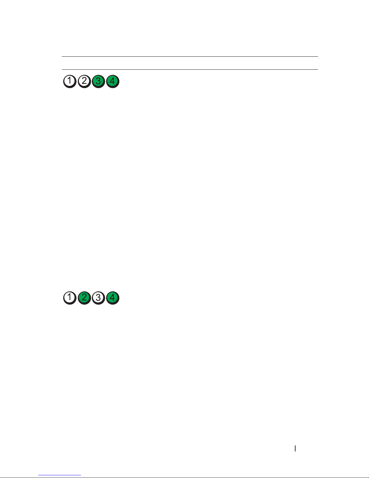
Light Pattern Problem Description Suggested Resolution
Memory modules are detected,
but a memory failure has
occurred.
• If you have one memory
module installed, reinstall it
and restart the computer (see
the online
User’s Guide
for
instructions on how to
remove and install memory
modules).
• If you have two or more
memory modules installed,
remove the modules, reinstall
one module, and then restart
the computer. If the
computer starts normally,
reinstall an additional
module. Continue until you
have identified a faulty
module or reinstalled all
modules without error.
• If available, install properly
working memory of the same
type into your computer.
A possible graphics card failure
has occurred.
• If the problem persists,
contact Dell
.
• If the computer has a
graphics card, remove the
card, reinstall it, and then
restart the computer.
• If the problem still exists,
install a graphics card that
you know works and restart
the computer.
• If the problem persists or the
computer has integrated
graphics,
technical assistance.
contact Dell for
For
information on contacting
Dell, see your online
.
Guide
User’s
Quick Reference Guide 57
Page 58
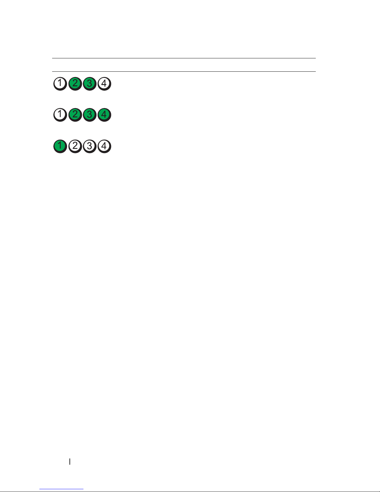
Light Pattern Problem Description Suggested Resolution
A possible floppy or hard drive
failure has occurred.
A possible USB failure has
occurred.
No memory modules are
detected.
Reseat all power and data
cables and restart the
computer.
Reinstall all USB devices, check
cable connections, and then
restart the computer.
• If you have one memory
module installed, reinstall it
and restart the computer (see
the online
User’s Guide
for
instructions on how to
remove and install memory
modules).
• If you have two or more
memory modules installed,
remove the modules, reinstall
one module, and then restart
the computer. If the
computer starts normally,
reinstall an additional
module. Continue until you
have identified a faulty
module or reinstalled all
modules without error.
58 Quick Reference Guide
• If available, install properly
working memory of the same
type into your computer.
• If the problem persists,
contact Dell for technical
assistance.
For information
on contacting Dell, see your
online
User’s Guide
.
Page 59
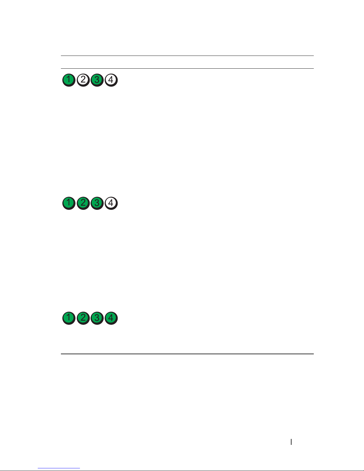
Light Pattern Problem Description Suggested Resolution
Memory modules are detected,
but a memory configuration or
compatibility error exists.
A failure has occurred.
This pattern also displays when
you enter the system setup
program and may not indicate
a problem (see "System Setup
Program" in your computer’s
online User’s Guide).
• Ensure that no
memory module/memory
connector placement
requirements
• Verify that the
modules
installing are compatible with
your computer.
• If the problem persists,
contact Dell for technical
assistance.
on contacting Dell, see your
online
• Ensure that the cables are
properly connected to the
system board from the hard
drive, and optical drive.
• Check the computer message
that appears on your monitor
screen.
that you are
User’s Guide
special
exist.
memory
For information
.
• If the problem persists,
contact Dell for technical
For information
User’s Guide
.
After POST is complete, all
four diagnostic lights turn
green briefly before turning off
to indicate normal operating
condition.
assistance.
on contacting Dell, see your
online
None.
Beep Codes
Your computer might emit a series of beeps during start-up if the monitor
cannot display errors or problems. This series of beeps, called a beep code,
identifies a problem.
Quick Reference Guide 59
Page 60

If your computer beeps during start-up:
1
Write down the beep code.
2
See "Dell Diagnostics" on page 51 to identify a more serious cause.
3
Contact Dell for technical assistance. For information on contacting Dell,
see your online
Code Cause
2 short, 1 long BIOS checksum error
1 long, 2 short Memory test failure (bad memory during memory sizing)
1 long, 3 short, 2 short No memory
1 short <F12> key pressed
User’s Guide
.
Resolving Software and Hardware Incompatibilities
If a device is either not detected during the operating system setup or is
detected but incorrectly configured, you can use the Hardware
Troubleshooter to resolve the incompatibility.
Windows Vista
1
2
Click
Ty p e
Start
and click
Help and Support.
hardware troubleshooter
in the search field and press
<Enter> to start the search.
In the search results, select the option that best describes the problem and
follow the remaining troubleshooting steps.
Windows XP
1
2
Click
Ty p e
Start→
Help and Support
.
hardware troubleshooter
in the search field and press
<Enter> to start the search.
3
In the
4
In the
the problem and click
Fix a Problem
section, click
Hardware Troubleshooter
Next
to follow the remaining troubleshooting steps.
Hardware Troubleshooter
.
list, select the option that best describes
60 Quick Reference Guide
Page 61

Restoring Your Operating System
The Microsoft Windows operating system provides System Restore to allow
you to return your computer to an earlier operating state (without affecting
data files) if changes to the hardware, software, or other system settings have
left the computer in an undesirable operating state. See the Windows Help
and Support Center for information on using System Restore.
NOTICE: Make regular backups of your data files. System Restore does not
monitor your data files or recover them.
Windows Vista
Starting System Restore
1
2
Click
In the
Start
.
Start Search
NOTE: The User Account Control window may appear. If you are an
administrator on the computer, click Continue; otherwise, contact your
administrator to continue the desired action.
box, type
System Restore
and press <Enter>.
3
Click
Next
and follow the remaining prompts on the screen.
In the event that System Restore did not resolve the issue, you may undo the
last system restore.
Undoing the Last System Restore
NOTICE: Before you undo the last system restore, save and close all open files and
exit any open programs. Do not alter, open, or delete any files or programs until the
system restoration is complete.
1
2
3
Click
In the
Click
Start
Start Search
.
box, type
System Restore
Undo my last restoration
and click
Next
and press <Enter>.
.
Quick Reference Guide 61
Page 62

Windows XP
Creating a Restore Point
1
Click the
2
Click
3
Follow the instructions on the screen.
Restoring the Computer to an Earlier Operating State
NOTICE: Before you restore the computer to an earlier operating state, save and
close any open files and exit any open programs. Do not alter, open, or delete any
files or programs until the system restoration is complete.
1
Click the
To ol s
2
Ensure that
Next
3
Click a calendar date to which you want to restore your computer.
Start
button and click
System Restore
Start
button, point to
, and then click
Restore my computer to an earlier time
.
Help and Support
.
All Programs→
System Restore
.
Accessories→
.
is selected and click
System
The
Select a Restore Point
screen provides a calendar that allows you to
see and select restore points. All calendar dates with available restore
points appear in boldface type.
4
Select a restore point and click
Next
.
If a calendar date has only one restore point, then that restore point is
automatically selected. If two or more restore points are available, click the
restore point that you prefer.
5
Click
The
Next
.
Restoration Complete
screen appears after System Restore finishes
collecting data and then the computer restarts.
6
After the computer restarts, click OK.
To change the restore point, you can either repeat the steps using a different
restore point, or you can undo the restoration.
62 Quick Reference Guide
Page 63

Undoing the Last System Restore
NOTICE: Before you undo the last system restore, save and close all open files and
exit any open programs. Do not alter, open, or delete any files or programs until the
system restoration is complete.
1
Click the
Tools
2
Click
3
Click
Start
button, point to
, and then click
System Restore
Undo my last restoration
Next
.
All Programs→ Accessories→ System
.
and click
Next
.
System Restore
The
4
After the computer restarts, click OK.
Enabling System Restore
screen appears and the computer restarts.
If you reinstall Windows XP with less than 200 MB of free hard-disk space
available, System Restore is automatically disabled. To see if System Restore
is enabled:
1
Click the
2
Click
3
Click
4
Click the
5
Ensure that
Start
button and click
Control Panel
Performance and Maintenance
System
.
System Restore
tab.
Turn off System Restore
.
.
is unchecked.
Reinstalling Your Microsoft Windows Operating System
To reinstall your operating system, see the instructions in the following
section that corresponds to the operating system your computer is running.
Windows Vista
The reinstallation process can take 1 to 2 hours to complete. After you
reinstall the operating system, you must also reinstall the device drivers, virus
protection program, and other software.
Save and close any open files and exit any open programs.
1
2
Insert the
3
Click
Operating System
Exit
if the
media.
Install Windows
message appears.
Quick Reference Guide 63
Page 64

4
Restart the computer.
When the DELL logo appears, press <F12> immediately.
NOTE: If you wait too long and the operating system logo appears, continue
to wait until you see the Microsoft
computer and try again.
NOTE: The next steps change the boot sequence for one time only. On the
next start-up, your computer boots according to the devices specified in the
system setup program.
5
When the boot device list appears, highlight
®
Windows® desktop; then, shut down your
CD/DVD/CD-RW Drive
and press <Enter>.
6
Press any key to
7
Follow the instructions on the screen to complete the installation.
Windows XP
NOTICE: You must use Windows XP Service Pack 1 or later when you reinstall your
operating system.
Before You Begin
Boot from CD-ROM
.
If you are considering reinstalling the Microsoft Windows operating system to
correct a problem with a newly installed driver, first try using Device Driver
Rollback (see "Using Windows Device Driver Rollback" on page 68 for more
information). If Device Driver Rollback does not resolve the problem, then
use System Restore (see "Restoring Your Operating System" on page 61 for
more information) to return your operating system to the operating state it
was in before you installed the new device driver.
NOTICE: Before performing the installation, back up all data files on your primary
hard drive. For conventional hard drive configurations, the primary hard drive is the
first drive detected by the computer.
To reinstall Windows XP, you need the following items:
•Dell™
•Dell
NOTE: The Drivers and Utilities media contains drivers that were installed during
assembly of the computer. Use the Drivers and Utilities media to load any required
drivers.
Operating System
Drivers and Utilities
64 Quick Reference Guide
media
media
Page 65

To reinstall Windows XP, perform all the steps in the following sections in the
order in which they are listed.
The reinstallation process can take 1 to 2 hours to complete. After you
reinstall the operating system, you must also reinstall the device drivers, virus
protection program, and other software.
NOTICE: The Operating System media provides options for reinstalling
Windows XP. The options can overwrite files and possibly affect programs installed
on your hard drive. Therefore, do not reinstall Windows XP unless a Dell technical
support representative instructs you to do so.
NOTICE: To prevent conflicts with Windows XP, disable any virus protection
software installed on your computer before you reinstall Windows XP. See the
documentation that came with the software for instructions.
Booting From the Operating System Media
1
Save and close any open files and exit any open programs.
2
Insert the
XP
message appears.
Operating System
media. Click
Exit
if
Install Windows
3
Restart the computer.
4
Press <F12> immediately after the DELL™ logo appears.
If the operating system logo appears, wait until you see the Windows
desktop, and then shut down the computer and try again.
5
Press the arrow keys to select
6
When the
Press any key to boot from CD
CD-ROM
, and press <Enter>.
message appears,
press any key.
Windows XP Setup
1
When the
set up Windows now
2
Read the information on the
Windows XP Setup
.
Microsoft Windows Licensing Agreement
screen appears, press <Enter> to select
screen, and press <F8> to accept the license agreement.
3
If your computer already has Windows XP installed and you want to
recover your current Windows XP data, type
r
to select the repair option,
and remove the media.
To
Quick Reference Guide 65
Page 66

4
If you want to install a new copy of Windows XP, press <Esc> to select
that option.
5
Press <Enter> to select the highlighted partition (recommended), and
follow the instructions on the screen.
The
Windows XP Setup
screen appears, and the operating system begins
to copy files and install the devices. The computer automatically restarts
multiple times.
NOTICE: Do not press any key when the following message appears: Press
Next
.
screen appears, select the
.
Personalize Your
window, enter a
any key to boot from the CD
NOTE: The time required to complete the setup depends on the size of the hard
drive and the speed of your computer.
6
When the
Regional and Language Options
settings for your location and click
7
Enter your name and organization (optional) in the
Software
8
At the
screen, and click
Computer Name and Administrator Password
Next
.
name for your computer (or accept the one provided) and a password, and
click
Next
.
9
If the
information and click
10
Enter the date, time, and time zone in the
window, and click
11
If the
12
If you are reinstalling Windows XP Professional and you are prompted to
Modem Dialing Information
Next
.
Next
.
Networking Settings
screen appears, click
screen appears, enter the requested
Date and Time Settings
Typical
and click
provide further information regarding your network configuration, enter
your selections. If you are unsure of your settings, accept the default
selections.
Windows XP installs the operating system components and configures the
computer. The computer automatically restarts.
NOTICE: Do not press any key when the following message appears: Press
Skip
.
Next
.
.
any key to boot from the CD
13
When the
14
When the
Internet?
Welcome to Microsoft
How will this computer connect to the
message appears, click
screen appears, click
Next
.
66 Quick Reference Guide
Page 67

15
When the
at this time
16
When the
Ready to register with Microsoft?
and click
Who will use this computer?
Next
.
screen appears, you can enter up
screen appears, select
to five users.
17
Click
18
Click
19
Reinstall the appropriate drivers with the
20
Reinstall your virus protection software.
21
Reinstall your programs.
NOTE: To reinstall and activate your Microsoft Office or Microsoft Works Suite
programs, you need the Product Key number located on the back of the Microsoft
Office or Microsoft Works Suite media sleeve.
Next
.
Finish
to complete the setup, and remove the media.
Drivers and Utilities
media.
Using the Drivers and Utilities Media
NOTICE: The Drivers and Utilities media may contain drivers for operating systems
that are not on your computer. Ensure that you are installing software appropriate
for your operating system.
No, not
Many drivers, such as the keyboard driver, come with your Microsoft
Windows operating system. You may need to install drivers if you:
• Upgrade your operating system.
• Reinstall your operating system.
• Connect or install a new device.
Identifying Drivers
If you experience a problem with any device, identify whether the driver is the
source of your problem and, if necessary, update the driver.
Windows Vista
1
Click
2
Click
NOTE: The User Account Control window may appear. If you are an
®
Start
and right-click
Properties→ Device Manager
administrator on the computer, click Continue; otherwise, contact your
administrator to continue.
Computer
.
.
Quick Reference Guide 67
Page 68

Scroll down the list to see if any device has an exclamation point (a yellow
circle with a [!]) on the device icon.
If an exclamation point is next to the device name, you may need to reinstall
the driver or install a new driver (see "Reinstalling Drivers and Utilities" on
page 68).
Windows® XP
1
Click
2
Under
System
3
In the
Manager
Reinstalling Drivers and Utilities
NOTICE: The Dell Support website at support.dell.com and your Drivers and
Utilities media provide approved drivers for Dell™ computers. If you install drivers
obtained from other sources, your computer might not work correctly.
Start→
Control Panel
Pick a Category
.
System Properties
.
.
, click
Performance and Maintenance
window, click the
Hardware
, and click
tab, and click
Device
Using Windows Device Driver Rollback
If a problem occurs on your computer after you install or update a driver, use
Windows Device Driver Rollback to replace the driver with the previously
installed version.
If Device Driver Rollback does not resolve the problem, then use System
Restore (see "Restoring Your Operating System" on page 61) to return your
computer to the operating state that existed before you installed the new
driver.
Windows Vista:
1
Click
2
Click
3
Right-click the device for which the new driver was installed and click
Properties
Start
Properties→ Device Manager
NOTE: The User Account Control window may appear. If you are an
administrator on the computer, click Continue; otherwise, contact your
administrator to enter the Device Manager.
and right-click
Computer
.
.
.
4
Click the
Drivers
tab→ Roll Back Driver
68 Quick Reference Guide
.
Page 69

Windows XP:
1
Click
2
Right-click the device for which the new driver was installed and click
Properties
3
Click the
Manually Reinstalling Drivers
Start→
.
Drivers
My Computer→ Properties→ Hardware→
tab→
Roll Back Driver
.
Device Manager
After extracting the driver files to your hard drive as described in the previous
section:
Windows Vista:
1
Click
2
Click
3
Double-click the type of device for which you are installing the driver (for
example,
Start
and right-click
Properties→ Device Manager
NOTE: The User Account Control window may appear. If you are an
administrator on the computer, click Continue; otherwise, contact your
administrator to enter the Device Manager.
Audio
or
Video
).
Computer
.
.
.
4
Double-click the name of the device for which you are installing the driver.
5
Click the
software
6
Click
Driver
.
Browse
tab→
Update Driver→ Browse my computer for driver
and browse to the location to which you previously copied
the driver files.
7
When the name of the appropriate driver appears, click the name of the
8
driver
Click
→ OK→
Finish
Next
.
and restart your computer.
Windows XP:
1
Click
2
Double-click the type of device for which you are installing the driver (for
example,
3
Double-click the name of the device for which you are installing the driver.
4
Click the
5
Click
Start→ My Computer→ Properties→ Hardware→ Device Manager
Audio
Driver
or
Video
tab→
).
Update Driver
.
Install from a list or specific location (Advanced)→ Next
.
.
Quick Reference Guide 69
Page 70

6
Click
Browse
and browse to the location to which you previously copied
the driver files.
7
When the name of the appropriate driver appears, click
8
Click
Finish
and restart your computer.
Next
.
70 Quick Reference Guide
Page 71

Index
B
beep codes, 59
C
CDs
operating system, 8
computer
restore to previous state, 61
conflicts
software and hardware
incompatibilities, 60
cover
opening, 38
removing, 32
regulatory, 6
safety, 6
User’s Guide, 6
warranty, 6
drivers
identifying, 67
reinstalling, 68
Drivers and Utilities CD, 5
E
End User License Agreement, 6
ergonomics information, 6
error messages
beep codes, 59
system lights, 54
D
Dell Diagnostics, 51
Dell support site, 9
diagnostics
beep codes, 59
Dell Diagnostics, 51
documentation
End User License Agreement, 6
ergonomics, 6
online, 9
Product Information Guide, 6
H
hardware
beep codes, 59
conflicts, 60
Dell Diagnostics, 51
Hardware Troubleshooter, 60
Help and Support Center, 10
help file
Windows Help and Support
Center, 10
Index 71
Page 72

I
problems. See troubleshooting
installing parts
before you begin, 32
IRQ conflicts, 60
L
labels
Microsoft Windows, 7
Service Tag, 7
lights
power, 22, 28
system, 54
M
motherboard. See system board
Product Information Guide, 6
R
regulatory information, 6
reinstalling
Windows Vista, 63
Windows XP, 64
S
safety instructions, 6
Service Tag, 7
software
conflicts, 60
support website, 9
O
operating system
reinstalling, 8
Operating System CD, 8
P
power
light, 22, 28
power light
diagnosing problems with, 54
problems
restore to previous state, 61
system board, 40, 45, 48
System Restore, 61
T
troubleshooting
beep codes, 59
conflicts, 60
Dell Diagnostics, 51
Hardware Troubleshooter, 60
Help and Support Center, 10
restore to previous state, 61
system lights, 54
72 Index
Page 73

U
User’s Guide, 6
W
warranty information, 6
Windows Vista
Hardware Troubleshooter, 60
Help and Support Center, 10
reinstalling, 63
System Restore, 61
Windows XP
Device Driver Rollback, 68
Hardware Troubleshooter, 60
Help and Support Center, 10
reinstalling, 8, 64
System Restore, 61
Index 73
Page 74

74 Index
Page 75

Guide de référence rapide du
Dell™ OptiPlex™ 740
Modèles DCSM, DCNE, DCCY
www.dell.com | support.dell.com
Page 76

Remarques, avis et précautions
REMARQUE : Une REMARQUE fournit des informations importantes qui vous
aident à mieux utiliser votre ordinateur.
AVIS : Un AVIS vous avertit d’un risque d'endommagement du matériel ou de perte
de données et vous indique comment éviter le problème.
PRÉCAUTION : Une PRÉCAUTION indique un risque potentiel d'endommagement
du matériel, de blessure corporelle ou de mort.
Si vous avez acheté un ordinateur Dell™ série n, aucune des références faites
®
dans ce document aux systèmes d'exploitation Microsoft
applicable.
Windows® n'est
____________________
Les informations de ce document sont sujettes à modifications sans préavis.
© 2008 Dell Inc. Tous droits réservés.
La reproduction de ce document, de quelque manière que ce soit, sans l'autorisation écrite de Dell Inc.
est strictement interdite.
Marques utilisées dans ce document : Dell, OptiPlex et le logo DELL sont des marques de Dell Inc. ;
Microsoft, Windows, Windows Vista et le bouton Démarrer de Windows Vista sont des marques
déposées de Microsoft Corporation.
D'autres marques et noms commerciaux peuvent être utilisés dans ce document pour faire référence
aux entités se réclamant de ces marques et de ces noms ou à leurs produits. Dell Inc. rejette tout intérêt
propriétaire dans les marques et les noms commerciaux autres que les siens.
Modèles DCSM, DCNE, DCCY
Janvier 2008 Réf. HX166 Rév. A01
Page 77

Table des matières
Recherche d'informations . . . . . . . . . . . . . . . . 79
Configuration de votre ordinateur
Vues du système
. . . . . . . . . . . . . . . . . . . . . 88
Ordinateur mini-tour — Vue frontale
Ordinateur mini-tour — Vue arrière
. . . . . . . . . . . . 84
. . . . . . . . 88
. . . . . . . . 91
Ordinateur mini-tour — Connecteurs du panneau
arrière
Ordinateur de bureau — Vue frontale
Ordinateur de bureau — Vue arrière
. . . . . . . . . . . . . . . . . . . . . . . . 93
. . . . . . . 95
. . . . . . . . 97
Ordinateur de bureau — Connecteurs du
panneau arrière
Ordinateur compact — Vue frontale
Ordinateur compact — Vue arrière
. . . . . . . . . . . . . . . . . . . 99
. . . . . . . . 101
. . . . . . . . 104
Ordinateur compact — Connecteurs du
panneau arrière
Retrait du capot de l'ordinateur
. . . . . . . . . . . . . . . . . . . 105
. . . . . . . . . . . . . 107
L'intérieur de votre ordinateur
Avant de commencer
Ordinateur mini-tour
Ordinateur de bureau
Ordinateur compact
Ordinateur mini-tour
Ordinateur de bureau
Ordinateur compact
. . . . . . . . . . . . . . . . 107
. . . . . . . . . . . . . . . . 109
. . . . . . . . . . . . . . . . 111
. . . . . . . . . . . . . . . . 113
. . . . . . . . . . . . . 114
. . . . . . . . . . . . . . . . 114
. . . . . . . . . . . . . . . . 118
. . . . . . . . . . . . . . . . 123
Table des matières 77
Page 78

Résolution des problèmes . . . . . . . . . . . . . . . 126
Dell Diagnostics
Voyants du système
Voyants de diagnostic
Codes sonores
. . . . . . . . . . . . . . . . . . 127
. . . . . . . . . . . . . . . . 130
. . . . . . . . . . . . . . . . . 132
. . . . . . . . . . . . . . . . . . 137
Résolution des incompatibilités logicielles et
matérielles
Restauration du système d'exploitation
. . . . . . . . . . . . . . . . . . . . 137
. . . . . 138
Réinstallation du système d'exploitation
Microsoft Windows
Utilisation du support Drivers and Utilities
. . . . . . . . . . . . . . . . 140
. . . . 144
Index . . . . . . . . . . . . . . . . . . . . . . . . . . . . . . 149
78 Table des matières
Page 79
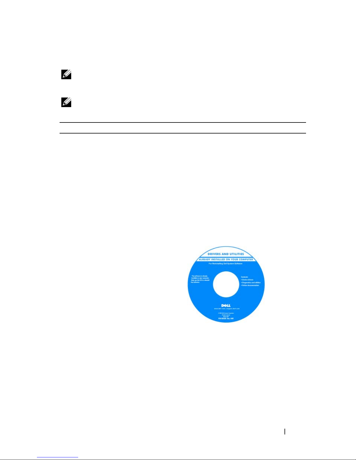
Recherche d'informations
REMARQUE : Certaines fonctionnalités ou supports peuvent être optionnels et ne
pas être intégrés à votre ordinateur. Certaines fonctionnalités ou supports peuvent
ne pas être disponibles dans certains pays.
REMARQUE : Il est possible que des informations supplémentaires soient fournies
avec votre ordinateur.
Que recherchez-vous ? Cherchez ici
• Programme de diagnostic pour mon
ordinateur
• Pilotes pour mon ordinateur
• Documentation de mon ordinateur
• Documentation concernant mon
appareil
• Logiciel DSS (Desktop System
Software)
Support Drivers and Utilities
REMARQUE : Il se peut que le support
Drivers and Utilities soit en option et qu'il
ne soit pas livré avec votre ordinateur.
La documentation et les pilotes sont déjà
installés sur l'ordinateur. Vous pouvez
utiliser le support Drivers and Utilities
pour réinstaller des pilotes (reportez-vous
à la section « Utilisation du support
Drivers and Utilities » à la page 144),
exécuter Dell Diagnostics (reportez-vous
à la section « Dell Diagnostics » à la
page 127) ou accéder à la documentation.
Des fichiers « Lisez-moi » peuvent être
inclus sur votre support (CD ou DVD),
qui fournissent les mises à jour les plus
récentes sur les modifications techniques
apportées à votre ordinateur ou des
informations de référence destinées aux
techniciens ou aux utilisateurs
expérimentés.
REMARQUE : Les dernières mises à jour
des pilotes et de la documentation se
trouvent à l'adresse support.dell.com.
Guide de référence rapide 79
Page 80
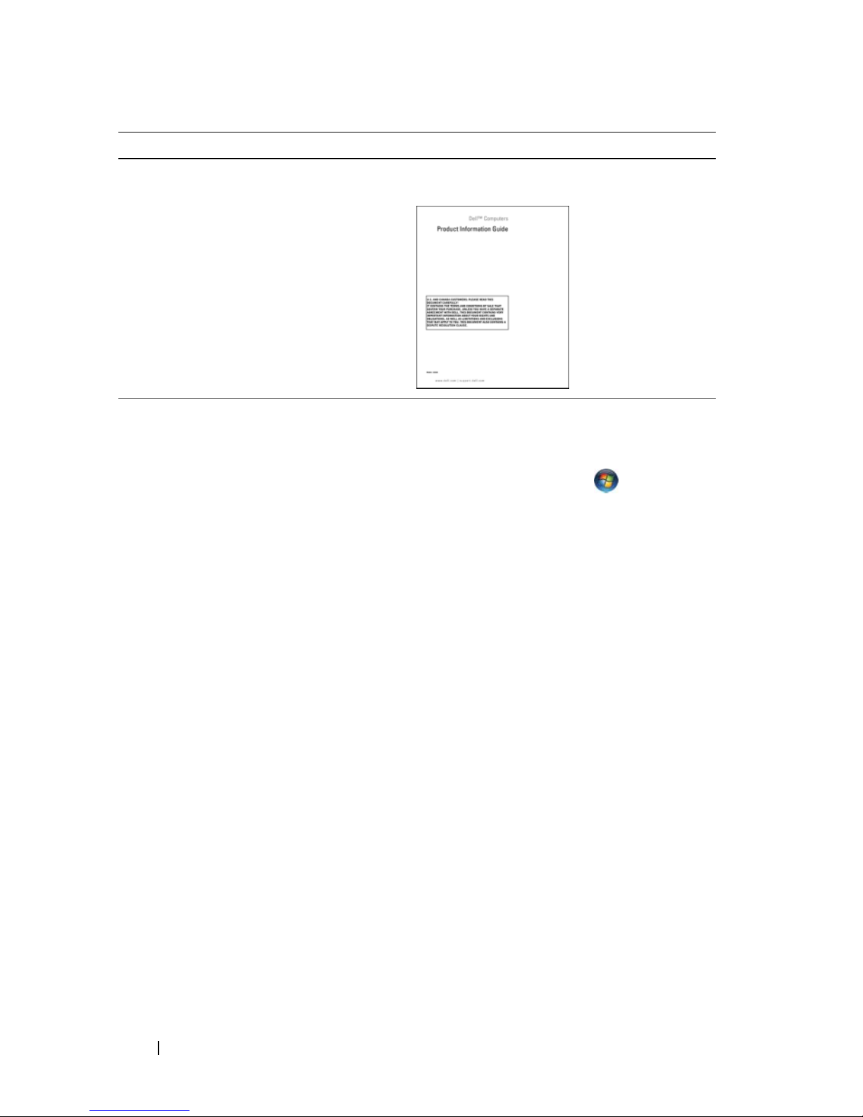
Que recherchez-vous ? Cherchez ici
• Informations sur les garanties
• Termes et Conditions (États-Unis
uniquement)
• Consignes de sécurité
• Informations réglementaires
• Informations relatives à l'ergonomie
• Contrat de licence utilisateur final
• Comment retirer et remplacer des
pièces
• Caractéristiques
• Comment configurer les paramètres du
système
• Comment déterminer et résoudre des
problèmes
Guide d'information sur le produit Dell™
Guide d'utilisation du Dell™ OptiPlex™
Centre d'aide et de support Microsoft
Windows
1
Cliquez sur
support
système Dell
2
Cliquez sur le
Démarrer
→
Guides d'utilisation du
→
Guides du système
→
Guide d'utilisation
Aide et
de
.
votre ordinateur.
Le Guide d'utilisation est également
disponible sur le support Drivers and
Utilities en option.
80 Guide de référence rapide
Page 81
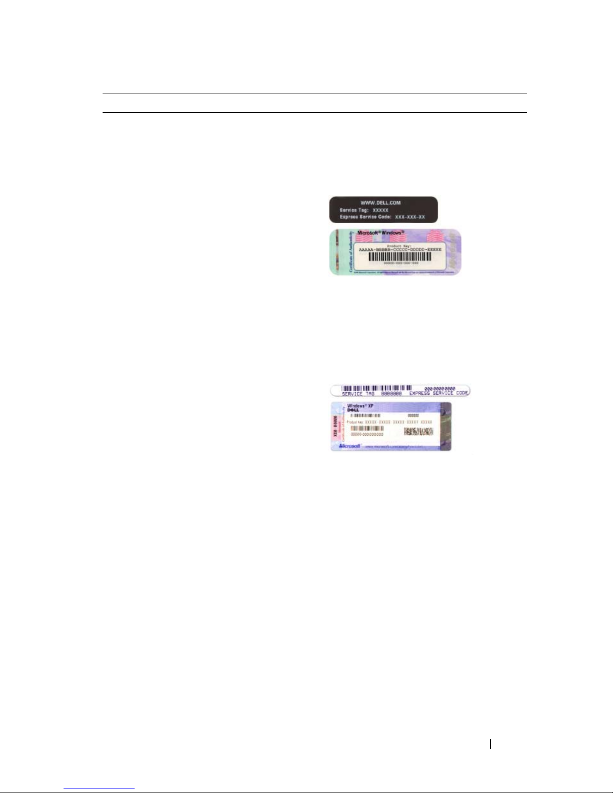
Que recherchez-vous ? Cherchez ici
• Numéro de service et code de service
express
• Étiquette de licence Microsoft
Windows
Numéro de service et licence Microsoft®
Windows
®
Ces étiquettes sont apposées à
l'ordinateur.
• Utilisez le numéro de service pour
identifier votre ordinateur lorsque vous
accédez au site Web
support.dell.com
ou lorsque vous contactez le service de
support.
• Entrez le code de service express pour
orienter votre appel lorsque vous
contactez le service de support.
Guide de référence rapide 81
Page 82
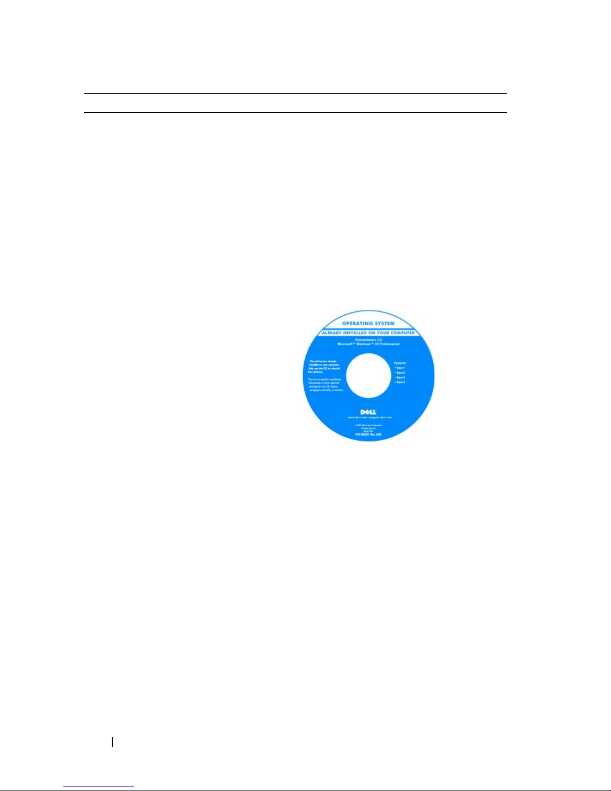
Que recherchez-vous ? Cherchez ici
• Comment réinstaller mon système
d'exploitation
Support Operating System
REMARQUE : Le support Operating
System peut être en option et n'est pas
obligatoirement expédié avec tous les
ordinateurs.
Le système d'exploitation est déjà installé
sur votre ordinateur. Pour le réinstaller,
utilisez le support Operating System.
Reportez-vous à la section
« Réinstallation du système d'exploitation
Microsoft Windows » à la page 140.
82 Guide de référence rapide
Après avoir réinstallé le système
d'exploitation, vous pouvez utiliser le
support Drivers and Utilities en option
pour réinstaller les pilotes des
périphériques fournis avec votre
ordinateur.
L'étiquette de la clé de produit du
système d'exploitation est apposée sur
l'ordinateur.
REMARQUE : La couleur de votre support
dépend du système d'exploitation que vous
avez commandé.
Page 83

Que recherchez-vous ? Cherchez ici
• Solutions — Conseils et astuces de
dépannage, articles de techniciens,
questions fréquemment posées et cours
en ligne
• Forum clients — Discussion en ligne
avec d'autres clients Dell
• Mises à niveau — Informations sur les
mises à niveau des composants, comme
la mémoire, l'unité de disque dur et le
système d'exploitation
• Service clientèle — Coordonnées,
appels de service et état des
commandes, garantie et informations
sur les réparations
• Service et support — État des appels de
service et historique du support, contrat
de service, discussions en ligne avec le
support technique
• Référence — Documentation de
l'ordinateur, détails sur la configuration
de l'ordinateur, caractéristiques de
produit et livres blancs
Site Web du service de support de Dell —
support.dell.com
REMARQUE : Sélectionnez votre région ou
votre secteur d'activité pour afficher le site
de support approprié.
• Téléchargements — Pilotes, correctifs
et mises à jour logicielles agréés
• DSS (Desktop System Software Logiciel système de bureau) — Si vous
réinstallez le système d'exploitation de
votre ordinateur, vous devez également
réinstaller l'utilitaire DSS. DSS fournit
des mises à jour essentielles pour le
système d'exploitation et la prise en
charge des lecteurs de disquette USB
Dell™ de 3,5 pouces, des processeurs,
des lecteurs optiques et des
périphériques USB. DSS est requis pour
le bon fonctionnement de votre
ordinateur Dell. Ce logiciel détecte
automatiquement votre ordinateur et
son système d'exploitation, et installe
les mises à jour appropriées à votre
configuration.
Pour télécharger DSS (Desktop System
Software) :
1
Rendez-vous sur le site
support.dell.com
, sélectionnez votre
région ou secteur d'activité, puis
saisissez votre numéro de service.
2
Sélectionnez
Drivers & Downloads
(Pilotes et téléchargements) et cliquez
Go/OK
sur
3
Cliquez sur votre système d'exploitation
et recherchez le mot-clé
Software
.
Desktop System
.
REMARQUE : L'interface utilisateur
support.dell.com peut varier en fonction de
vos sélections.
Guide de référence rapide 83
Page 84
Que recherchez-vous ? Cherchez ici
• Comment utiliser Windows Vista® ou
Windows
• Comment utiliser des programmes et
des fichiers
• Comment personnaliser mon bureau
®
XP
Centre d'aide et de support de Windows
1
Pour accéder à l'aide et au support de
Windows :
•
Sous Windows Vista
Démarrer
Sous Windows XP
•
Démarrer
2
Entrez un mot ou une expression qui
décrit votre problème, puis cliquez sur
l'icône en forme de flèche.
3
Cliquez sur la rubrique qui décrit votre
problème.
4
Suivez les instructions qui s'affichent.
→ Aide et support
, cliquez sur
→
Aide et support
, cliquez sur
Configuration de votre ordinateur
PRÉCAUTION : Avant de commencer toute procédure de cette section, lisez les
consignes de sécurité du Guide d'information sur le produit.
AVIS : Si votre ordinateur est doté d'une carte d'extension (une carte modem par
exemple), branchez le câble approprié sur la carte et non pas sur le connecteur du
panneau arrière.
.
.
AVIS : Pour garantir une bonne température de fonctionnement de l'ordinateur,
.
veillez à ne pas placer l'ordinateur trop près d'un mur ou d'un compartiment de
rangement pouvant empêcher une bonne circulation de l'air autour du châssis.
REMARQUE : Avant d'installer tout périphérique ou logiciel qui n'a pas été livré
avec votre ordinateur, lisez attentivement la documentation fournie avec le logiciel
ou le périphérique ou contactez votre fournisseur, afin de vous assurer que le
logiciel ou l'appareil est compatible avec votre ordinateur et votre système
d'exploitation.
Votre ordinateur sera correctement configuré uniquement lorsque toutes ces
étapes seront réalisées. Reportez-vous aux illustrations appropriées qui
suivent les instructions.
84 Guide de référence rapide
Page 85
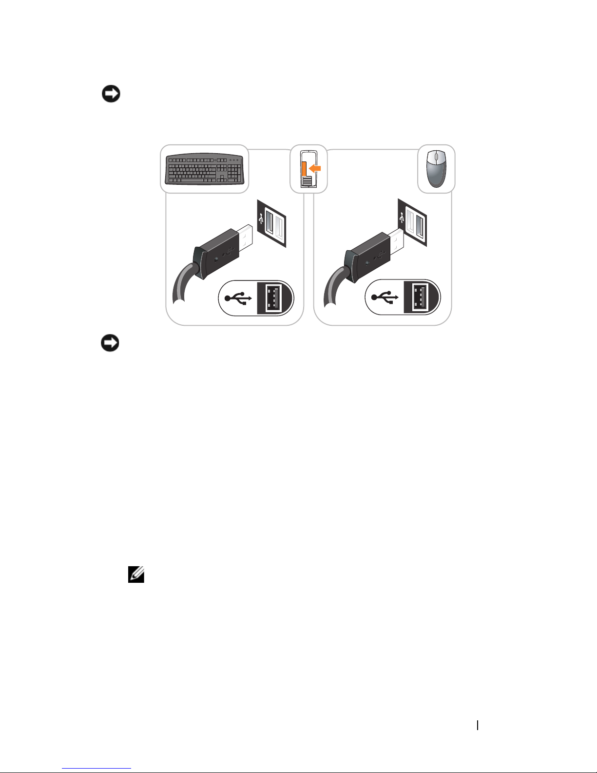
AVIS : N'utilisez pas simultanément une souris PS/2 et une souris USB.
1
Branchez le clavier et la souris.
AVIS : Ne branchez pas de ligne téléphonique dans le connecteur d'adaptateur
réseau. En effet, la tension des communications téléphoniques risquerait de
l'endommager.
2
Branchez la ligne téléphonique ou le câble réseau.
Insérez le câble réseau, et non la ligne téléphonique, dans le connecteur
réseau. Si vous disposez d'un modem optionnel, connectez la ligne
téléphonique à ce dernier.
3
Connectez le moniteur UNIQUEMENT à l'aide de l'un des câbles
suivants : le câble DVI blanc ou le câble VGA bleu (ne connectez pas ces
deux câbles au même ordinateur).
Alignez, puis insérez avec précaution le câble du moniteur de manière à ne
pas tordre les broches du connecteur. Resserrez les vis moletées des
connecteurs de câble.
REMARQUE : Sur certains moniteurs, le connecteur vidéo est placé sous
l'arrière de l'écran. Consultez la documentation fournie avec votre moniteur
pour connaître les emplacements des connecteurs.
Guide de référence rapide 85
Page 86
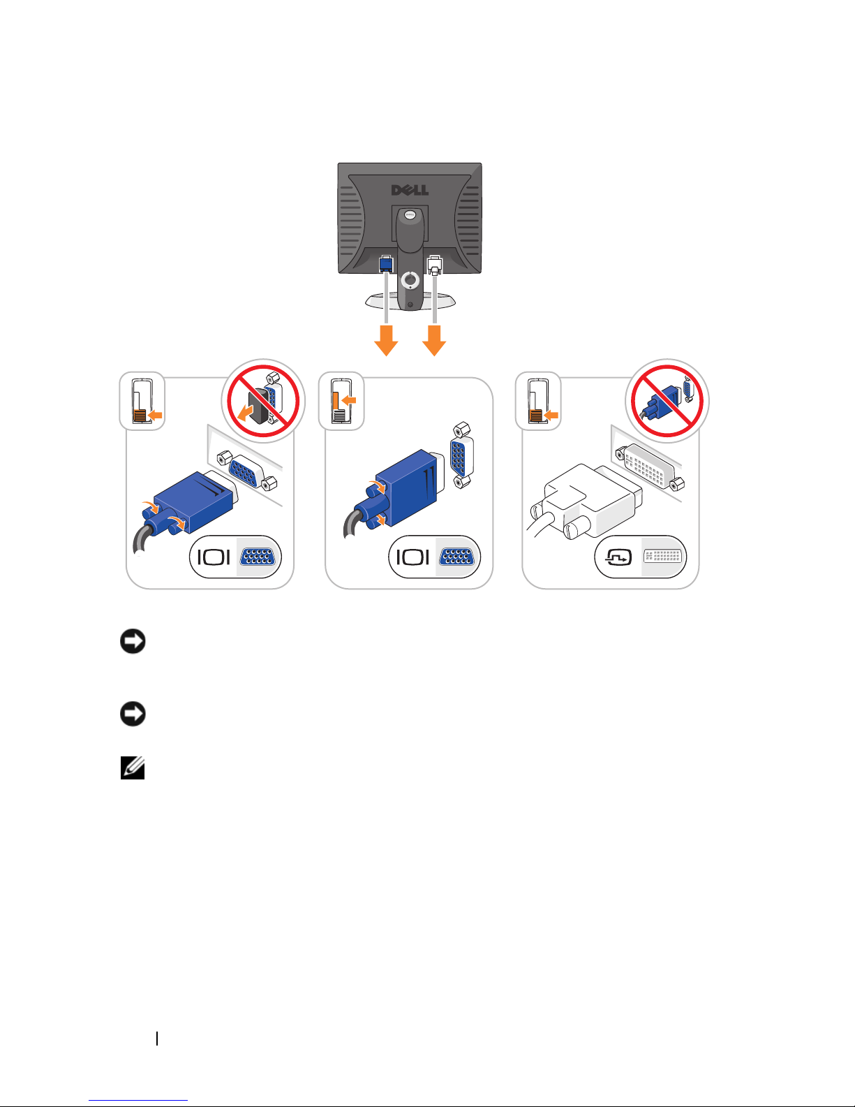
4
Branchez les haut-parleurs.
AVIS : Pour éviter d'endommager l'ordinateur, réglez le sélecteur de tension
manuel (si votre ordinateur dispose d'un sélecteur de tension, il se trouve à
l'arrière) sur la tension la plus proche de l'alimentation disponible.
AVIS : Au Japon, le sélecteur de tension doit être placé en position 115 V même si
la tension disponible au Japon est de 100 V.
REMARQUE : Il se peut que le bloc d'alimentation de votre ordinateur ne dispose
pas d'un sélecteur de tension.
5
Vérifiez que le sélecteur de tension indique la tension appropriée à votre
zone géographique.
Votre ordinateur est équipé d'un sélecteur de tension manuel. Les
ordinateurs dotés d'un sélecteur de tension sur leur panneau arrière
doivent être réglés manuellement, en fonction de la tension disponible.
86 Guide de référence rapide
Page 87
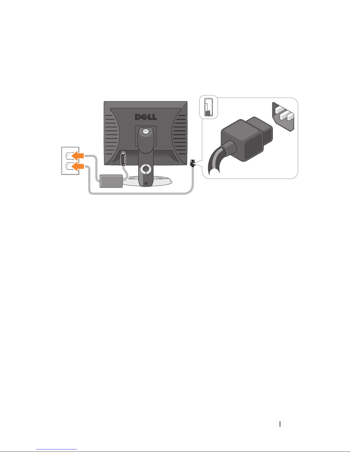
6
Branchez les câbles d'alimentation à l'ordinateur, au moniteur et aux
périphériques, puis insérez les autres extrémités des câbles dans des prises
électriques.
Guide de référence rapide 87
Page 88
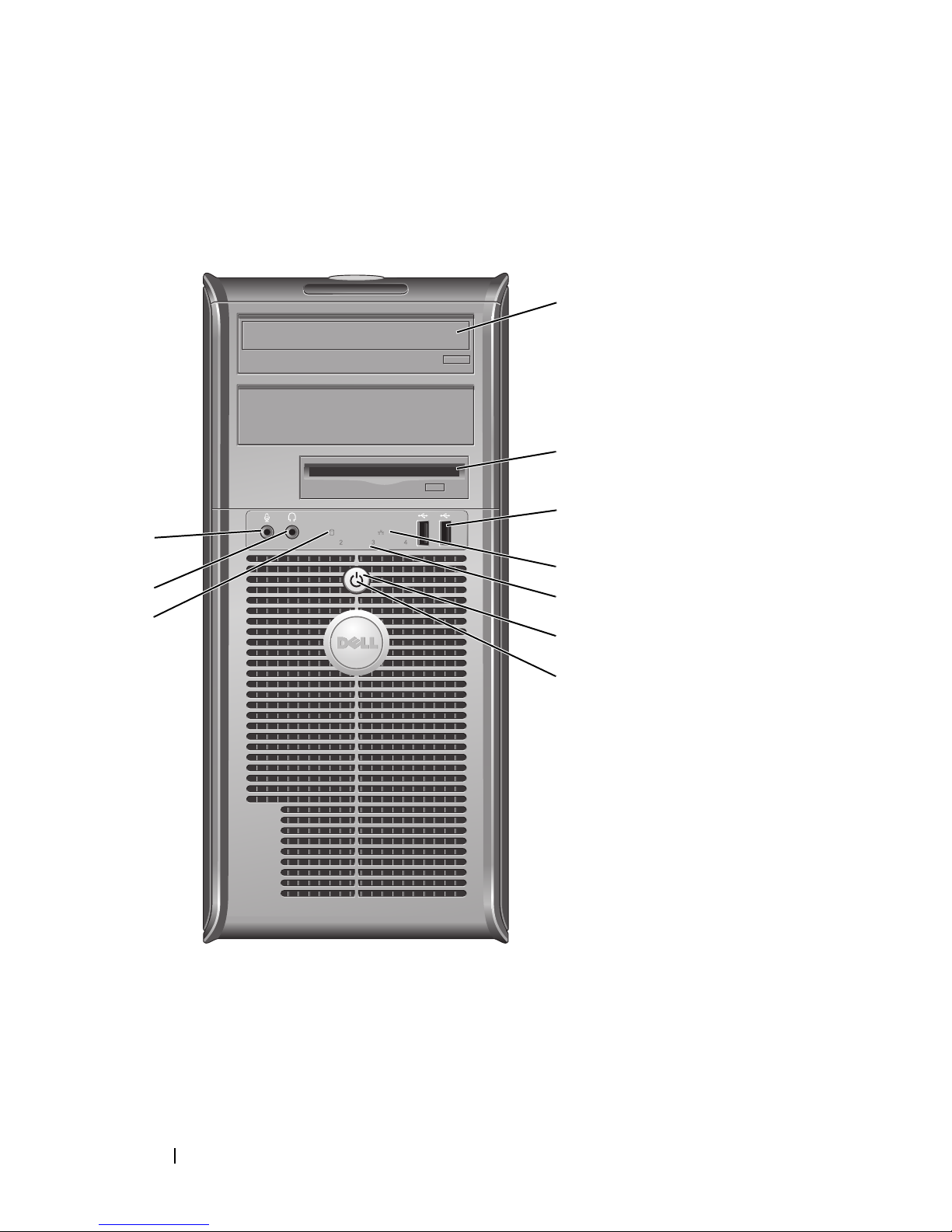
Vues du système
Ordinateur mini-tour — Vue frontale
10
9
8
1
2
3
4
5
6
7
88 Guide de référence rapide
Page 89

1 lecteur
optique (en
option)
Insérez un lecteur optique (si celui-ci est pris en charge) dans
cette baie.
2 baie de lecteur
de disquette
Peut contenir un lecteur de disquette ou un lecteur de carte
multimédia optionnel.
(en option)
3 connecteurs
USB 2.0 (2)
Utilisez les connecteurs USB frontaux pour connecter les
périphériques dont vous ne vous servez qu'occasionnellement,
tels qu'une manette de jeu ou un appareil photo, ou des
périphériques USB amorçables (reportez-vous à la section
« Options de configuration du système » dans le Guide
d'utilisation en ligne pour de plus amples informations sur
l'amorçage à partir d'un périphérique USB).
Il est recommandé d'utiliser les connecteurs USB situés à
l'arrière pour les périphériques connectés en permanence,
comme l'imprimante et le clavier.
4 voyant LAN Ce voyant indique qu'une connexion LAN (réseau local) est
établie.
5 voyants de
diagnostic
Ces voyants vous aident à résoudre les problèmes
informatiques d'après le code de diagnostic. Pour de plus
amples informations, reportez-vous à la section «Voyants de
diagnostic » à la page 132.
6 bouton
d'alimentation
Appuyez sur ce bouton pour allumer l'ordinateur.
AVIS : Pour ne pas perdre de données, n'éteignez pas
l'ordinateur en appuyant sur le bouton d'alimentation.
Procédez plutôt à un arrêt du système d'exploitation. Pour
plus d'informations, reportez-vous à la section « Mise hors
tension de votre ordinateur » du Guide d'utilisation.
AVIS : Si la fonctionnalité ACPI est activée sur votre
système d'exploitation, lorsque vous appuyez sur le bouton
d'alimentation, l'ordinateur procède à un arrêt du système
d'exploitation.
Guide de référence rapide 89
Page 90

7 voyant
d'alimentation
Le voyant d'alimentation s'allume et clignote ou reste fixe,
selon le mode de fonctionnement :
• Éteint — L'ordinateur est éteint.
• Vert fixe — L'ordinateur fonctionne normalement.
• Vert clignotant — L'ordinateur est en mode d'économie
d'énergie.
• Orange clignotant ou fixe — Reportez-vous à la section
« Problèmes d'alimentation » du
Guide d'utilisation
en ligne.
Pour quitter le mode d'économie d'énergie, appuyez sur le
bouton d'alimentation ou utilisez le clavier ou la souris si ce
périphérique est configuré comme un périphérique de réveil
dans le Gestionnaire de périphériques Windows. Pour plus
d'informations sur les modes de mise en veille et sur la façon
de quitter le mode d'économie d'énergie, reportez-vous à la
section « Gestion de l'alimentation » du Guide d'utilisation.
Pour obtenir la description des codes lumineux pouvant vous
aider à résoudre les problèmes rencontrés avec votre
ordinateur, reportez-vous à la section « Voyants du système »
à la page 130.
8 voyant
d'activité de
l'unité de
disque dur
9 connecteur de
casque
10 connecteur de
microphone
Ce voyant clignote rapidement lors de l'accès au disque dur.
Utilisez le connecteur de casque pour connecter le casque et la
plupart des haut-parleurs.
Utilisez le connecteur de microphone pour brancher un
microphone.
90 Guide de référence rapide
Page 91
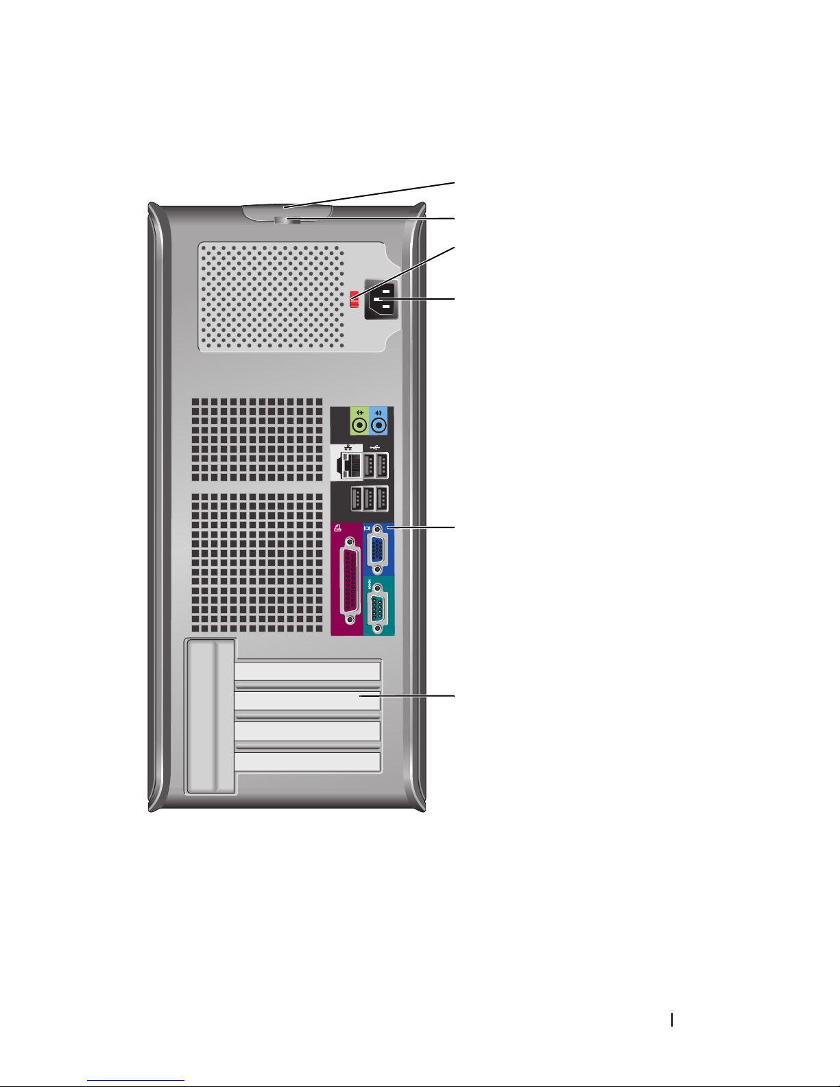
Ordinateur mini-tour — Vue arrière
1
2
3
4
5
6
Guide de référence rapide 91
Page 92

1 loquet du capot Ce loquet permet d'ouvrir le capot de l'ordinateur.
2 anneau pour
cadenas
3 sélecteur de
tension
4 connecteur
d'alimentation
5 connecteurs du
panneau arrière
Insérez un cadenas pour verrouiller le capot de l'ordinateur.
Votre ordinateur peut être équipé d'un sélecteur de tension
manuel.
Pour ne pas endommager un ordinateur doté d'un sélecteur
de tension manuel, réglez le sélecteur sur la tension qui
correspond le mieux à l'alimentation en CA de l'endroit où
vous vous trouvez :
AVIS : Au Japon, le sélecteur de tension doit être placé
en position 115 V même si la tension disponible au Japon
est de 100 V.
Assurez-vous également que votre moniteur et tous ses
périphériques sont électriquement réglés pour fonctionner
avec la puissance en CA disponible dans votre zone
géographique.
Insérez le câble d'alimentation.
Permettent de connecter les périphériques série, USB et les
autres périphériques à leurs connecteurs respectifs. Reportezvous à la section « Ordinateur mini-tour — Connecteurs du
panneau arrière » à la page 93.
6 logements de
carte (4)
Permettent d'accéder aux connecteurs de toutes les cartes
PCI et PCI Express installées.
92 Guide de référence rapide
Page 93
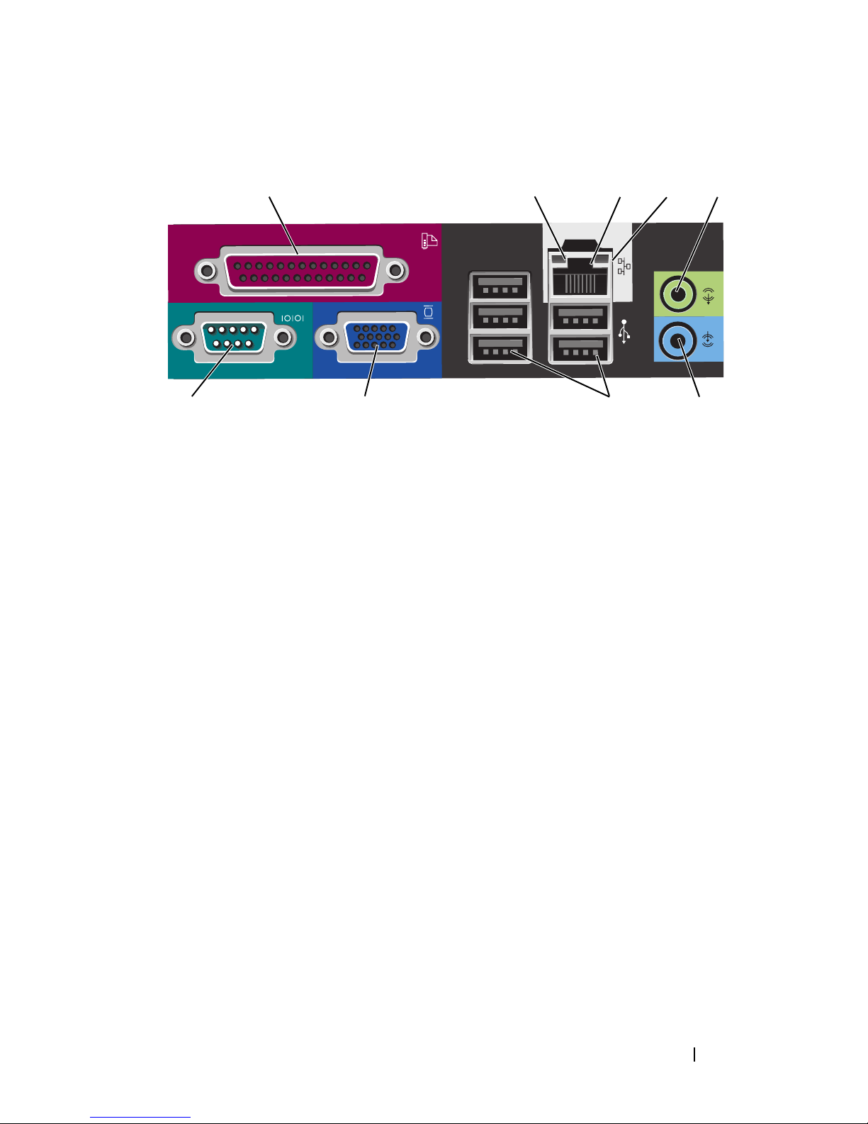
Ordinateur mini-tour — Connecteurs du panneau arrière
13
98 7
1 connecteur
parallèle
Permet de connecter un périphérique parallèle, tel qu'une
imprimante. Si vous avez une imprimante USB, raccordez-la
à un connecteur USB.
24
5
6
REMARQUE : Le connecteur parallèle intégré est
automatiquement désactivé si l'ordinateur détecte une carte
installée contenant un connecteur parallèle configuré sur la
même adresse. Pour de plus amples informations, reportezvous à la section « Programme de configuration du système »
de votre Guide d'utilisation en ligne.
2 voyant d'intégrité
de la liaison
• Vert — Une bonne connexion est établie entre le réseau
10 Mb/s et l'ordinateur.
• Orange — Une bonne connexion est établie entre le réseau
100 Mb/s et l'ordinateur.
• Jaune — Une bonne connexion est établie entre le réseau
1 Gb/s (ou 1000 Mb/s) et l'ordinateur.
• Éteint — L'ordinateur ne détecte pas de connexion
physique au réseau.
Guide de référence rapide 93
Page 94

3 connecteur de
carte réseau
Pour connecter l'ordinateur à un périphérique réseau ou
large bande, branchez l'une des extrémités d'un câble réseau
à une prise réseau, un périphérique réseau ou un
périphérique large bande. Connectez l'autre extrémité du
câble au connecteur de carte réseau situé sur le panneau
arrière de votre ordinateur. Un déclic indique que le câble
réseau a été correctement installé.
REMARQUE : Ne branchez pas un câble téléphonique au
connecteur de réseau.
Sur les ordinateurs équipés d'une carte réseau, utilisez le
connecteur situé sur la carte.
Il est recommandé d'utiliser un câblage et des connecteurs
de catégorie 5 pour le réseau. Si vous devez utiliser un
câblage de catégorie 3, forcez la vitesse du réseau à 10 Mb/s
pour garantir un fonctionnement fiable.
4 voyant d'activité
réseau
5 connecteur ligne
de sortie
6 connecteur de
ligne d'entrée
7 connecteurs
USB 2.0 (5)
8 connecteur vidéo Branchez le câble de votre moniteur compatible VGA dans
Un voyant jaune clignote lorsque l'ordinateur transmet ou
reçoit des données sur le réseau. Un trafic réseau important
peut donner l'impression que ce voyant est fixe.
Utilisez le connecteur ligne de sortie vert pour raccorder le
casque et la plupart des haut-parleurs dotés d'amplificateurs
intégrés.
Sur les ordinateurs équipés d'une carte son, utilisez le
connecteur qui se trouve sur cette carte.
Utilisez le connecteur de ligne d'entrée pour raccorder un
appareil d'enregistrement/de lecture, tel qu'un lecteur de
cassette, un lecteur de CD ou un magnétoscope.
Sur les ordinateurs équipés d'une carte son, utilisez le
connecteur qui se trouve sur cette carte.
Utilisez les connecteurs USB situés à l'arrière pour les
périphériques connectés en permanence, comme
l'imprimante et le clavier.
le connecteur bleu.
REMARQUE : Si vous avez acheté une carte graphique
optionnelle, ce connecteur sera recouvert d'un cache. Ne
retirez pas le cache. Connectez votre moniteur au connecteur
sur la carte graphique.
94 Guide de référence rapide
REMARQUE : Si vous utilisez une carte graphique capable de
gérer deux moniteurs, utilisez le câble en Y fourni avec
l'ordinateur.
Page 95
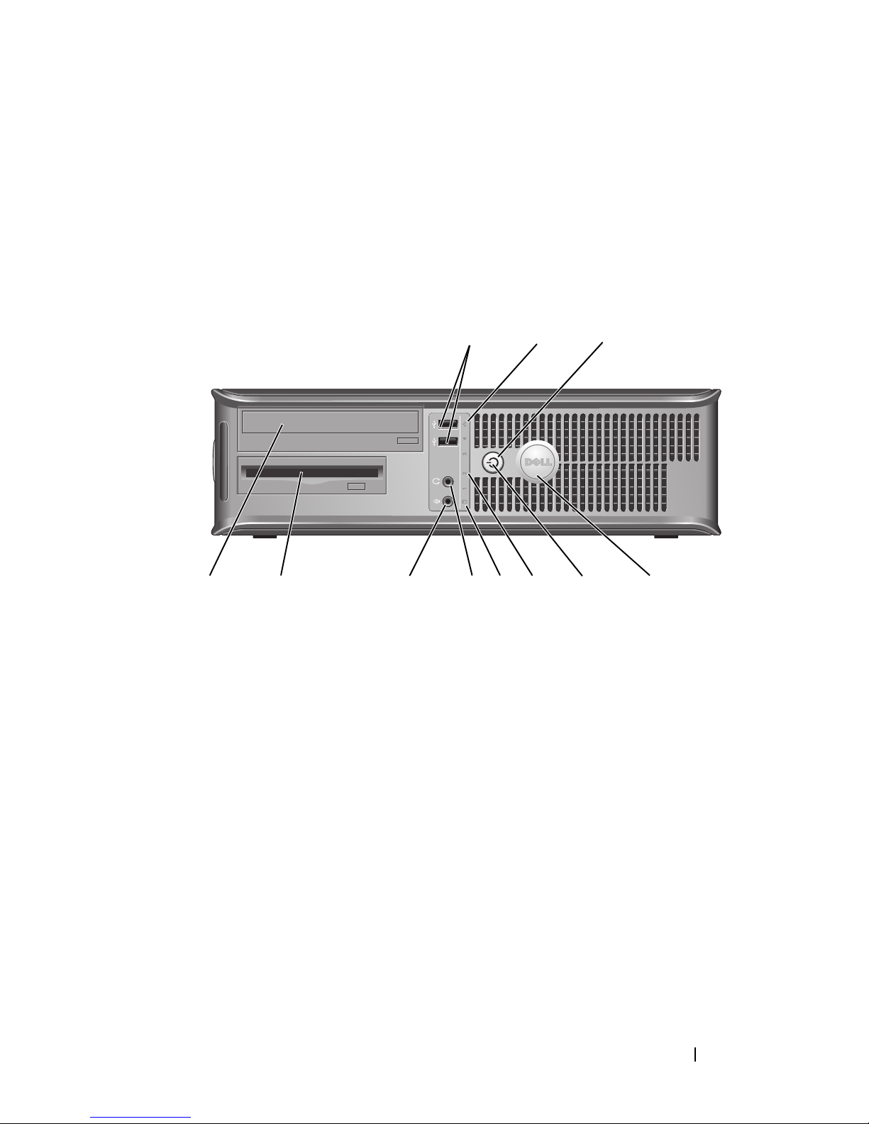
9 connecteur série Connectez un périphérique série, tel qu'un PDA, au port
série. Les désignations par défaut sont COM1 pour le
connecteur série 1 et COM2 pour le connecteur série 2.
Pour de plus amples informations, reportez-vous à la section
« Programme de configuration du système » de votre Guide
d'utilisation en ligne.
Ordinateur de bureau — Vue frontale
1 connecteurs
USB 2.0 (2)
1
89
2
7
3
5
4611 10
Utilisez les connecteurs USB frontaux pour connecter les
périphériques dont vous ne vous servez
qu'occasionnellement, tels qu'une manette de jeu ou un
appareil photo, ou des périphériques USB amorçables
(reportez-vous à la section « Programme de configuration
du système » dans le Guide d'utilisation en ligne pour de
plus amples informations sur l'amorçage à partir d'un
périphérique USB).
2 voyant LAN Ce voyant indique qu'une connexion LAN (réseau local)
Il est recommandé d'utiliser les connecteurs USB situés à
l'arrière pour les périphériques connectés en permanence,
comme l'imprimante et le clavier.
est établie.
Guide de référence rapide 95
Page 96

3 bouton
d'alimentation
4 badge Dell Vous pouvez faire pivoter ce badge pour l'aligner sur
Appuyez sur ce bouton pour allumer l'ordinateur.
AVIS : Pour ne pas perdre de données, n'éteignez pas
l'ordinateur en appuyant sur le bouton d'alimentation.
Procédez plutôt à un arrêt du système d'exploitation.
Pour plus d'informations, reportez-vous à la section
« Mise hors tension de votre ordinateur » du Guide
d'utilisation.
AVIS : Si la fonctionnalité ACPI est activée sur votre
système d'exploitation, lorsque vous appuyez sur le
bouton d'alimentation, l'ordinateur procède à un arrêt
du système d'exploitation.
l'orientation de votre ordinateur. Pour le faire tourner,
placez vos doigts sur l'extérieur du badge, appuyez
fermement et faites tourner le badge. Vous pouvez
également le faire pivoter à l'aide de l'encoche située vers le
bas du badge.
5 voyant
d'alimentation
Le voyant d'alimentation s'allume et clignote ou reste fixe,
selon l'état de fonctionnement :
• Éteint — L'ordinateur est éteint.
• Vert fixe — L'ordinateur fonctionne normalement.
• Vert clignotant — L'ordinateur est en mode d'économie
d'énergie.
• Orange clignotant ou fixe — Reportez-vous à la section
« Problèmes d'alimentation » du Guide d'utilisation en
ligne.
Pour quitter le mode d'économie d'énergie, appuyez sur le
bouton d'alimentation ou utilisez le clavier ou la souris si ce
périphérique est configuré comme un périphérique de
réveil dans le Gestionnaire de périphériques Windows.
Pour plus d'informations sur les modes de mise en veille et
sur la façon de quitter le mode d'économie d'énergie,
reportez-vous à la section « Gestion de l'alimentation » du
Guide d'utilisation en ligne.
Pour obtenir la description des codes lumineux pouvant
vous aider à résoudre les problèmes rencontrés avec votre
ordinateur, reportez-vous à la section « Voyants du
système » à la page 130.
96 Guide de référence rapide
Page 97
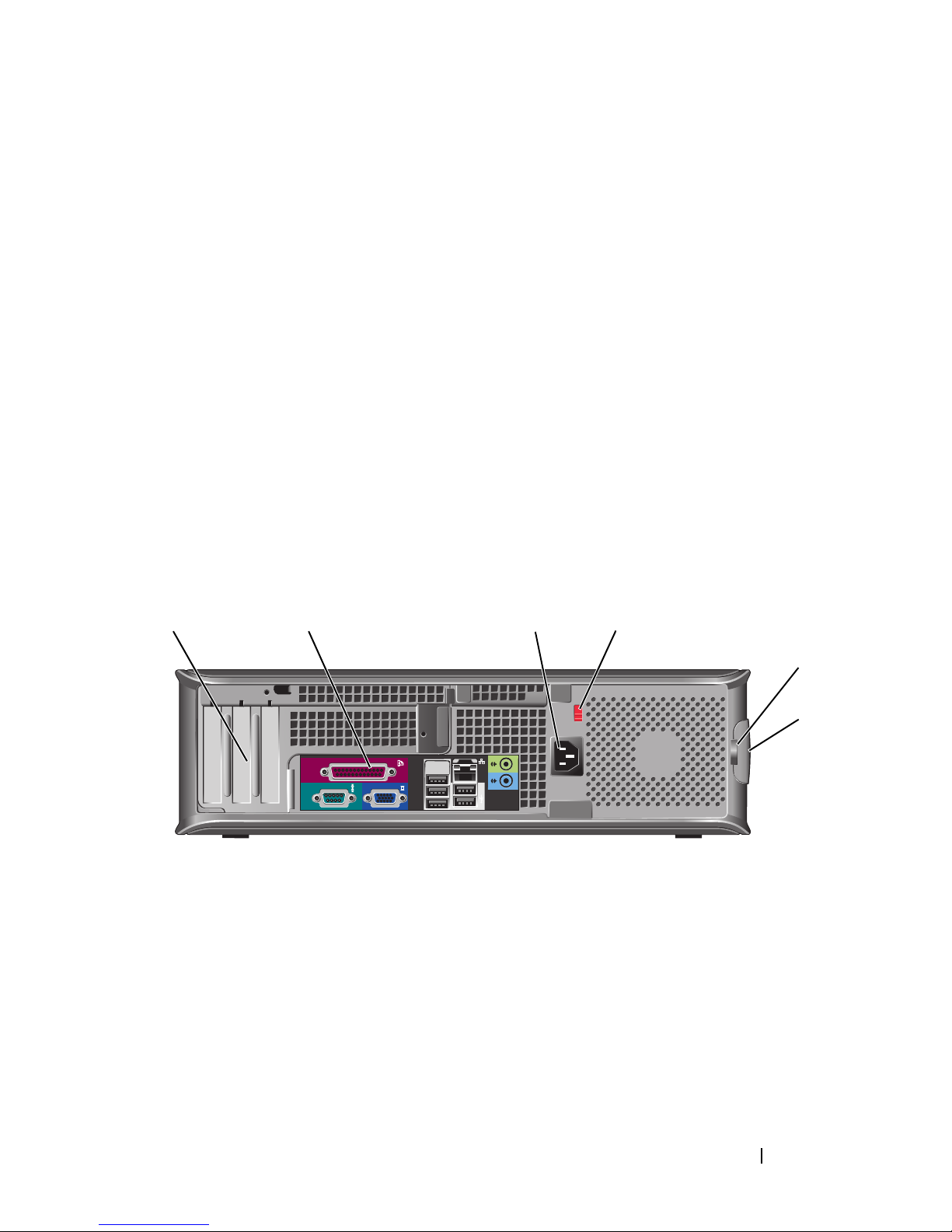
6 voyants de
diagnostic
Ces voyants vous aident à résoudre les problèmes
informatiques d'après le code de diagnostic. Pour de plus
amples informations, reportez-vous à la section «Voyants
de diagnostic » à la page 132.
7 voyant d'activité
de l'unité de
Ce voyant clignote rapidement lors de l'accès au disque
dur.
disque dur
8 connecteur de
casque
9 connecteur de
microphone
Utilisez le connecteur de casque pour connecter le casque
et la plupart des haut-parleurs.
Utilisez le connecteur de microphone pour brancher un
microphone.
10 baie d'unité Cette baie accueille un lecteur de disquette, un lecteur de
carte multimédia ou un deuxième disque dur en option.
11 lecteur optique
(en option)
Insérez un lecteur optique (si celui-ci est pris en charge)
dans cette baie.
Ordinateur de bureau — Vue arrière
1 2 3 4
5
1 logements de
carte (3)
2 connecteurs du
panneau arrière
3 connecteur
d'alimentation
6
Permettent d'accéder aux connecteurs de toutes les cartes
PCI et PCI Express installées.
Branchez les périphériques série, USB et tout autre
périphérique dans les connecteurs appropriés (reportez-vous
à la section « Ordinateur de bureau — Connecteurs du
panneau arrière » à la page 99).
Insérez le câble d'alimentation.
Guide de référence rapide 97
Page 98

4 sélecteur de
tension
REMARQUE : Il se peut que votre ordinateur ne dispose pas
d'un sélecteur de tension.
Votre ordinateur peut être équipé d'un sélecteur de tension
manuel.
Pour ne pas endommager un ordinateur doté d'un sélecteur
de tension manuel, réglez le commutateur sur la tension qui
correspond le mieux à l'alimentation en CA de l'endroit où
vous vous trouvez :
AVIS : Au Japon, le sélecteur de tension doit être placé
en position 115 V même si la tension disponible au Japon
est de 100 V.
Assurez-vous également que votre moniteur et tous ses
périphériques sont électriquement réglés pour fonctionner
avec la puissance en CA disponible dans votre zone
géographique.
5 anneau pour
cadenas
6 loquet du capot Permet d'ouvrir le capot de l'ordinateur.
Insérez un cadenas pour verrouiller le capot de l'ordinateur.
98 Guide de référence rapide
Page 99
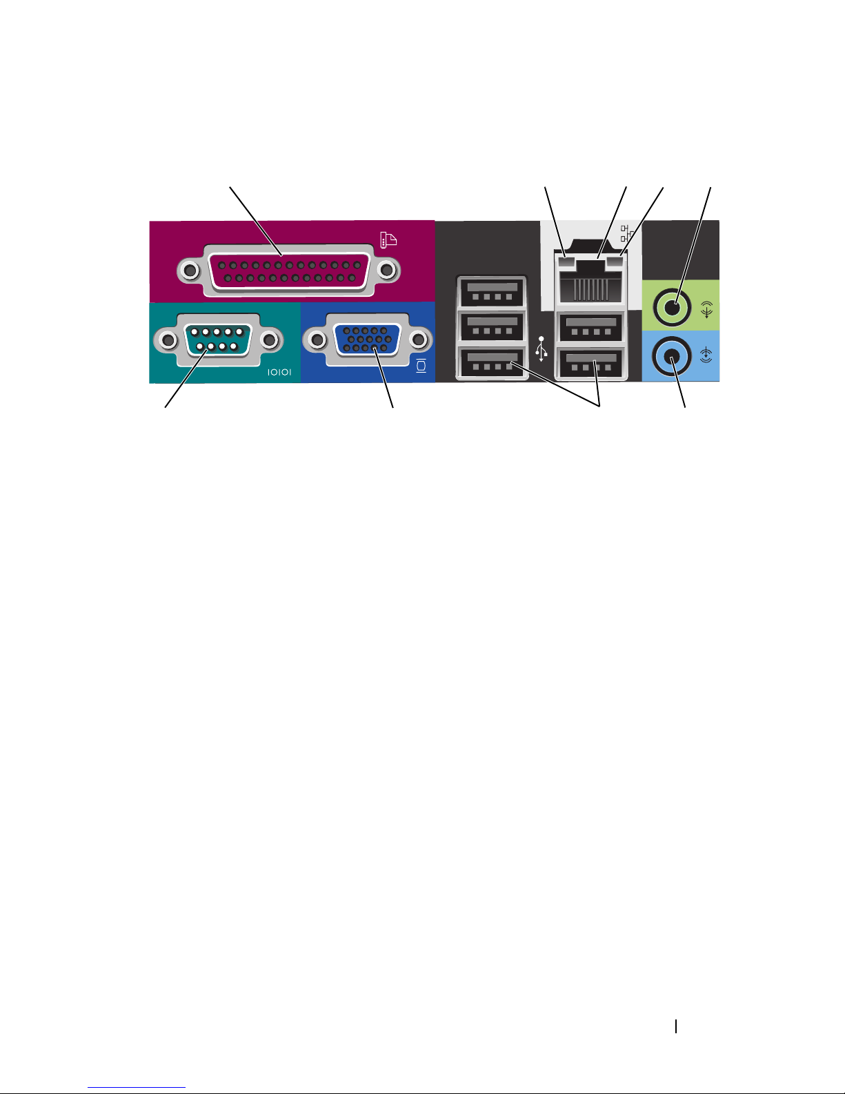
Ordinateur de bureau — Connecteurs du panneau arrière
13
987
1 connecteur
parallèle
Permet de connecter un périphérique parallèle, tel qu'une
imprimante. Si vous avez une imprimante USB, raccordezla à un connecteur USB.
24
5
6
REMARQUE : Le connecteur parallèle intégré est
automatiquement désactivé si l'ordinateur détecte une carte
installée contenant un connecteur parallèle configuré sur la
même adresse. Pour de plus amples informations, reportezvous à la section « Programmes de configuration du système »
de votre Guide d'utilisation en ligne.
2 voyant d'intégrité
de la liaison
• Vert — Une bonne connexion est établie entre le réseau
10 Mb/s et l'ordinateur.
• Orange — Une bonne connexion est établie entre le réseau
100 Mb/s et l'ordinateur.
• Jaune — Une bonne connexion est établie entre le réseau
1 Gb/s (ou 1000 Mb/s) et l'ordinateur.
• Éteint — L'ordinateur ne détecte pas de connexion
physique au réseau.
Guide de référence rapide 99
Page 100

3 connecteur de
carte réseau
Pour connecter l'ordinateur à un périphérique réseau ou
large bande, branchez l'une des extrémités d'un câble réseau
à une prise réseau, un périphérique réseau ou un
périphérique large bande. Connectez l'autre extrémité du
câble au connecteur de carte réseau situé sur le panneau
arrière de votre ordinateur. Un déclic indique que le câble
de réseau a été correctement installé.
REMARQUE : Ne branchez pas un câble téléphonique au
connecteur de réseau.
Sur les ordinateurs équipés d'une carte réseau, utilisez le
connecteur situé sur la carte.
Il est recommandé d'utiliser un câblage et des connecteurs
de catégorie 5 pour le réseau. Si vous devez utiliser un
câblage de catégorie 3, forcez la vitesse du réseau à 10 Mb/s
pour garantir un fonctionnement fiable.
4 voyant d'activité
réseau
5 connecteur ligne
de sortie
6 connecteur de
ligne d'entrée
7 connecteurs
USB 2.0 (5)
8 connecteur vidéo Branchez le câble de votre moniteur compatible VGA dans
Un voyant jaune clignote lorsque l'ordinateur transmet ou
reçoit des données sur le réseau. Un trafic réseau important
peut donner l'impression que ce voyant est fixe.
Utilisez le connecteur ligne de sortie vert pour raccorder le
casque et la plupart des haut-parleurs dotés
d'amplificateurs intégrés.
Sur les ordinateurs équipés d'une carte son, utilisez le
connecteur qui se trouve sur cette carte.
Utilisez le connecteur de ligne d'entrée pour raccorder un
appareil d'enregistrement/de lecture, tel qu'un lecteur de
cassette, un lecteur de CD ou un magnétoscope.
Sur les ordinateurs équipés d'une carte son, utilisez le
connecteur qui se trouve sur cette carte.
Utilisez les connecteurs USB situés à l'arrière pour les
périphériques connectés en permanence, comme
l'imprimante et le clavier.
le connecteur bleu.
REMARQUE : Si vous avez acheté une carte graphique
optionnelle, ce connecteur sera recouvert d'un cache. Ne
retirez pas le cache. Connectez votre moniteur au connecteur
sur la carte graphique.
100 Guide de référence rapide
REMARQUE : Si vous utilisez une carte graphique capable
de gérer deux moniteurs, utilisez le câble en Y fourni avec
l'ordinateur.
 Loading...