How it Works
Log In / Sign Up
Buy Points
How it Works
FAQ
Contact Us
Questions and Suggestions
Users
Dell
Loading...
O
OptiPlex 0F1697A00
OptiPlex 100-Mbps
OptiPlex 160
63
OptiPlex 160L
6
OptiPlex 170L
26
OptiPlex 170LN
OPTIPLEX 1906FP
OptiPlex 1U919
OptiPlex 1U920
OptiPlex 210L
23
OptiPlex 210LN
21
OptiPlex 270
OptiPlex 2U454
OptiPlex 3010
99
OPTIPLEX 3010 Desktop
OptiPlex 3010 Mini-Tower
OptiPlex 3011
68
OptiPlex 3011 AIO
7
OptiPlex 3011 All-in-One
3
OptiPlex 3020
78
OptiPlex 3020M
39
OptiPlex 3020–Mini Tower
2
OptiPlex 3020 MT
OptiPlex 3020 SFF
OptiPlex 3030
48
Optiplex 3030 AIO
OptiPlex 3030 All In One
2
Optiplex 3040
66
OptiPlex 3040M
OptiPlex 3040M Series
OptiPlex 3046
25
OptiPlex 3050
124
Optiplex 3050-0399
OptiPlex 3050 All-in-One
Optiplex 3050 Micro
2
OptiPlex 3050 Tower
OptiPlex 3060
202
OptiPlex 3060 Micro
3
OptiPlex 3060 Tower
OptiPlex 3070
OptiPlex 3070 micro
OptiPlex 3070 Small Form Factor
OptiPlex 3080
2
OptiPlex 3080 Micro
2
OptiPlex 3080 Small
OptiPlex 3090 Ultra
7
OptiPlex 320
24
OptiPlex 3240
45
OptiPlex 330
35
Optiplex 330 SFF
OptiPlex 360
59
OptiPlex 360 MT
2
OptiPlex 380
11
OptiPlex 380 Desktop
27
OptiPlex 380 Mini-Tower
27
OptiPlex 380 MT
OptiPlex 380 Small Form Factor
26
OptiPlex 38WYD
OptiPlex 390
15
OptiPlex 390 Desktop
OptiPlex 390 DT
OptiPlex 390 Mini-Tower
OptiPlex 390 MT
OptiPlex 390 SFF
OptiPlex 390 Small Form Factor
OptiPlex 3U083
OptiPlex 3WK82
OptiPlex 486
OptiPlex 486/L
OptiPlex 486/LE
OptiPlex 486/M
OptiPlex 486/ME
OptiPlex 486/MXE
OptiPlex 486/SL
OptiPlex 5040
50
Optiplex 5040-9976
OptiPlex 5040 Series
OptiPlex 5040 SFF
OptiPlex 5040 Small Form Factor
OptiPlex 5050
82
Optiplex 5050-8299
OptiPlex 5055
70
OptiPlex 5060
222
OptiPlex 5060 Micro
OPTIPLEX 5070
72
OptiPlex 5070 MFF
OptiPlex 5070 Micro
OptiPlex 5070 MT
OptiPlex 5070 SFF
OptiPlex 5080 Micro
OptiPlex 5080 MT
2
OptiPlex 5080 SFF
2
OptiPlex 5250
44
Optiplex 5260
2
OptiPlex 5260 All-in-One
OptiPlex 5270
57
OptiPlex 5270 All-in-One
OptiPlex 5490 All-In-One
OptiPlex 580
90
OptiPlex 580 Desktop
28
Loading...
Loading...
Nothing found
OptiPlex 360
User Manual
160 pgs
13.82 Mb
0
Brochure & Specs
2 pgs
353.55 Kb
0
Service Manual
82 pgs
2.43 Mb
0
Setup And Quick Reference Manual
62 pgs
1.1 Mb
0
Technical Manualbook
27 pgs
929.78 Kb
0
User Manual
62 pgs
1.86 Mb
0
User Manual [ar]
62 pgs
2.74 Mb
0
User Manual [ar]
82 pgs
2.57 Mb
0
User Manual [cr]
80 pgs
2.57 Mb
0
User Manual [cr]
72 pgs
4.9 Mb
0
User Manual [cs]
80 pgs
2.68 Mb
0
User Manual [cs]
68 pgs
4.74 Mb
0
User Manual [da]
81 pgs
2.51 Mb
0
User Manual [da]
68 pgs
1.51 Mb
0
User Manual [de]
70 pgs
1.53 Mb
0
User Manual [de]
84 pgs
2.51 Mb
0
User Manual [es]
84 pgs
2.49 Mb
0
User Manual [es]
70 pgs
1.53 Mb
0
User Manual [fi]
80 pgs
2.48 Mb
0
User Manual [fi]
68 pgs
1.49 Mb
0
User Manual [fr]
83 pgs
2.44 Mb
0
User Manual [fr]
68 pgs
1.56 Mb
0
User Manual [gr]
78 pgs
5.32 Mb
0
User Manual [gr]
83 pgs
2.58 Mb
0
User Manual [he]
78 pgs
2.58 Mb
0
User Manual [he]
62 pgs
1.1 Mb
0
User Manual [hu]
70 pgs
4.82 Mb
0
User Manual [hu]
80 pgs
2.54 Mb
0
User Manual [in]
83 pgs
2.52 Mb
0
User Manual [in]
68 pgs
1.52 Mb
0
User Manual [ja]
68 pgs
2.09 Mb
0
User Manual [ja]
80 pgs
2.88 Mb
0
User Manual [ko]
68 pgs
7.38 Mb
0
User Manual [ko]
82 pgs
2.71 Mb
0
User Manual [nl]
84 pgs
2.48 Mb
0
User Manual [nl]
68 pgs
1.48 Mb
0
User Manual [no]
81 pgs
2.48 Mb
0
User Manual [no]
66 pgs
1.46 Mb
0
User Manual [po]
74 pgs
1.68 Mb
0
User Manual [po]
84 pgs
2.66 Mb
0
User Manual [pt]
70 pgs
1.47 Mb
0
User Manual [pt]
72 pgs
1.67 Mb
0
User Manual [pt]
82 pgs
2.5 Mb
0
User Manual [pt]
83 pgs
2.49 Mb
0
User Manual [ro]
70 pgs
4.77 Mb
0
User Manual [ro]
83 pgs
2.65 Mb
0
User Manual [ru]
74 pgs
5.04 Mb
0
User Manual [ru]
83 pgs
2.6 Mb
0
User Manual [si]
68 pgs
4.95 Mb
0
User Manual [si]
80 pgs
2.55 Mb
0
User Manual [sk]
68 pgs
1.59 Mb
0
User Manual [sk]
80 pgs
2.61 Mb
0
User Manual [sv]
80 pgs
2.48 Mb
0
User Manual [sv]
64 pgs
1.45 Mb
0
User Manual [tr]
62 pgs
1.91 Mb
0
User Manual [tr]
80 pgs
2.7 Mb
0
User Manual [zh]
81 pgs
3.03 Mb
0
User Manual [zh]
60 pgs
2.25 Mb
0
User Manual [zh]
79 pgs
2.86 Mb
0
Table of contents
Loading...
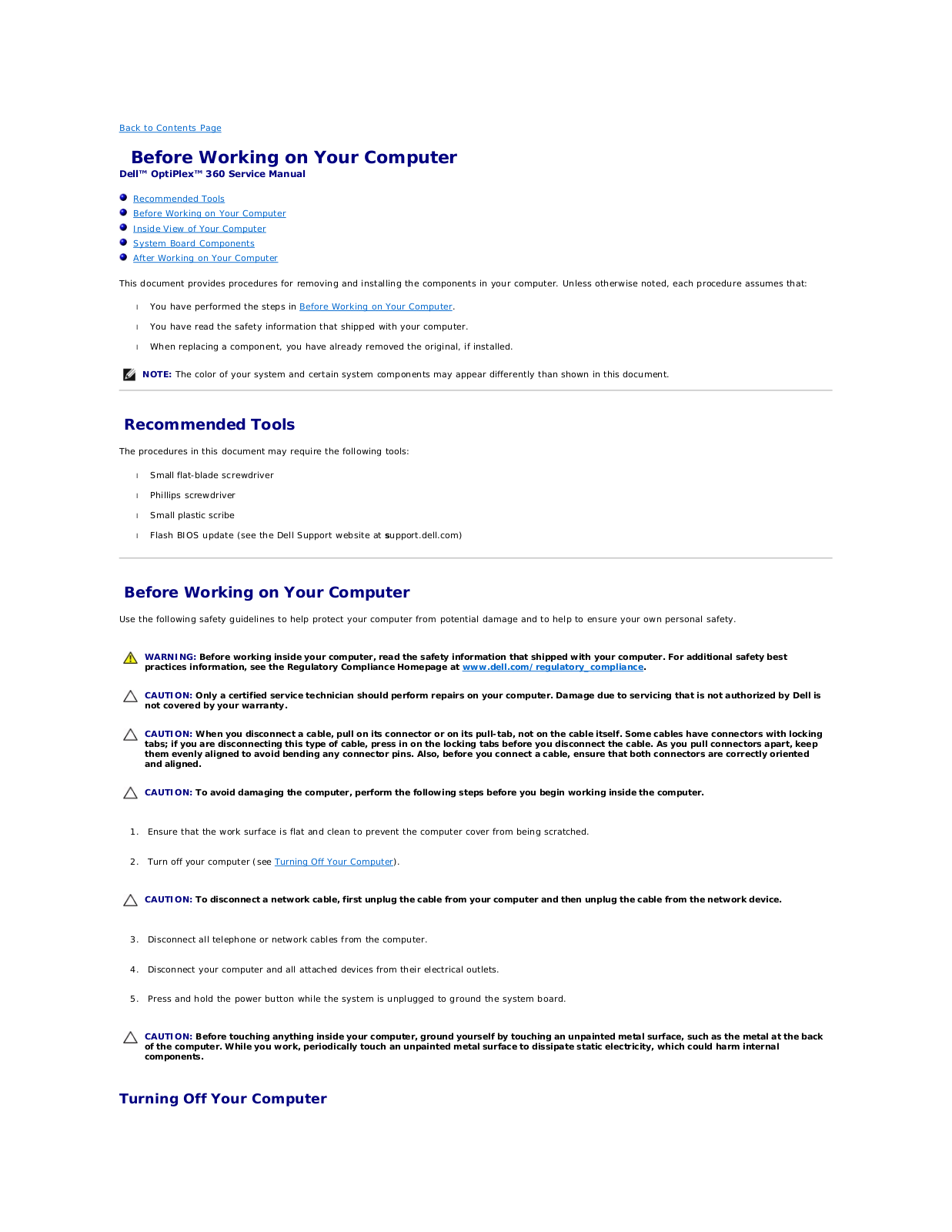
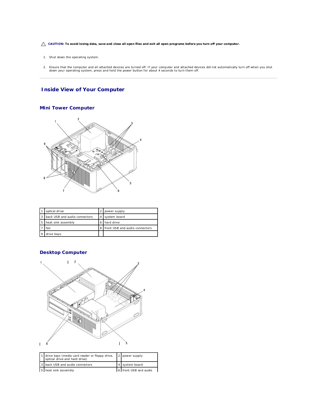
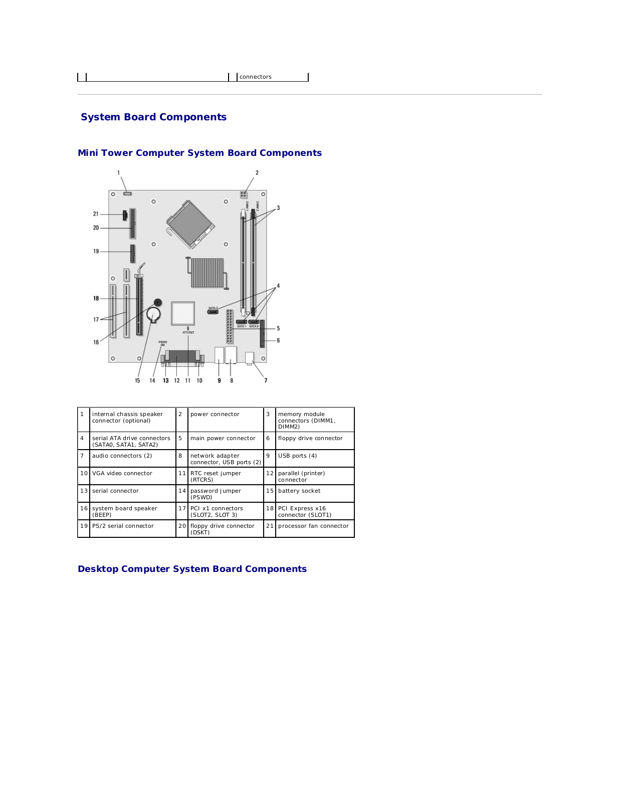
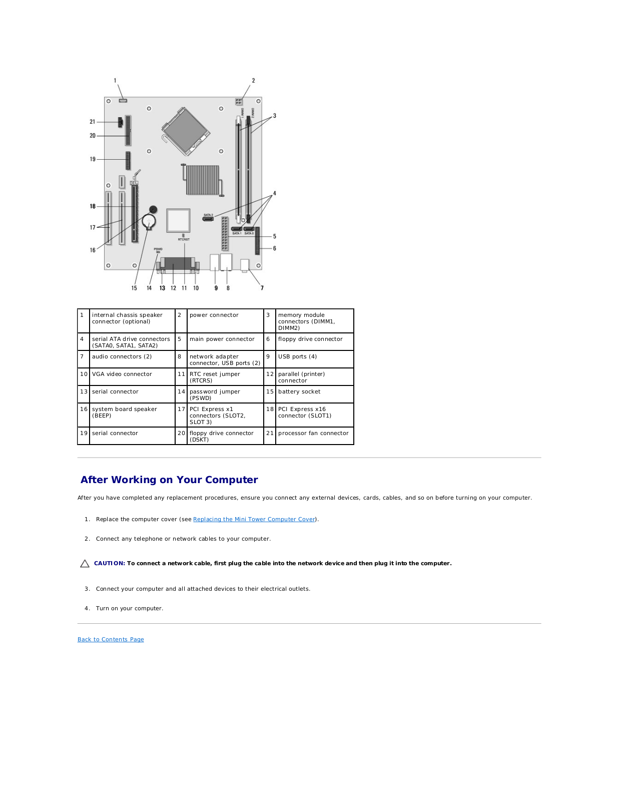
Dell OptiPlex 360 Service Manual
...
Dell Service Manual
Download
Specifications and Main Features
Frequently Asked Questions
User Manual
Download
Loading...
+
57
hidden pages
Unhide
You need points to download manuals.
1 point = 1 manual.
You can buy points or you can get point for every manual you upload.
Buy points
Upload your manuals
 Loading...