

Page 1

Dell™ OptiPlex™ 320
Quick Reference Guide
Models DCSM, DCNE
www.dell.com | support.dell.com
Page 2

Notes, Notices, and Cautions
NOTE: A NOTE indicates important information that helps you make better use of your computer.
NOTICE: A NOTICE indicates either potential damage to hardware or loss of data and tells you how to avoid the
problem.
CAUTION: A CAUTION indicates a potential for property damage, personal injury, or death.
If you purchased a Dell™ n Series computer, any references in this document to Microsoft® Windows®
operating systems are not applicable.
____________________
Information in this document is subject to change without notice.
© 2006 Dell Inc. All rights reserved.
Reproduction in any manner whatsoever without the written permission of Dell Inc. is strictly forbidden.
Trademarks used in this text: Dell, OptiPlex, and the DELL logo are trademarks of Dell Inc.; Microsoft and Windows are registered trademarks
of Microsoft Corporation; Intel and Pentium are registered trademarks of Intel Corporation.
Other trademarks and trade names may be used in this document to refer to either the entities claiming the marks and names or their products.
Dell Inc. disclaims any proprietary interest in trademarks and trade names other than its own.
Models DCSM, DCNE
September 2006 P/N KK074 Rev. A01
Page 3

Contents
Finding Information . . . . . . . . . . . . . . . . . . . . . . . . . . . . . . . . 5
Setting Up Your Computer
System Views
. . . . . . . . . . . . . . . . . . . . . . . . . . . . . . . . . . 11
Mini Tower Computer — Front View
Mini Tower Computer — Back View
. . . . . . . . . . . . . . . . . . . . . . . . . . . . . 8
. . . . . . . . . . . . . . . . . . . . 11
. . . . . . . . . . . . . . . . . . . . 13
Mini Tower Computer — Back-Panel Connectors
Desktop Computer — Front View
Desktop Computer — Back View
. . . . . . . . . . . . . . . . . . . . . . 16
. . . . . . . . . . . . . . . . . . . . . . 17
Desktop Computer — Back-Panel Connectors
Removing the Computer Cover
Before You Begin
Mini Tower Computer
Desktop Computer
Inside Your Computer
Mini Tower Computer
Desktop Computer
Solving Problems
Dell Diagnostics
System Lights
Diagnostic Lights
Beep Codes
. . . . . . . . . . . . . . . . . . . . . . . . . . . . . . . . 30
. . . . . . . . . . . . . . . . . . . . . . . . . . . . . . . 30
. . . . . . . . . . . . . . . . . . . . . . . . . . . . . . . . 33
. . . . . . . . . . . . . . . . . . . . . . . . . . . . . . . . . 34
. . . . . . . . . . . . . . . . . . . . . . . . . . . . . . . . . 37
. . . . . . . . . . . . . . . . . . . . . . . . . . 20
. . . . . . . . . . . . . . . . . . . . . . . . . . . . . . 20
. . . . . . . . . . . . . . . . . . . . . . . . . . . . 21
. . . . . . . . . . . . . . . . . . . . . . . . . . . . . 23
. . . . . . . . . . . . . . . . . . . . . . . . . . . . . . 24
. . . . . . . . . . . . . . . . . . . . . . . . . . . . 24
. . . . . . . . . . . . . . . . . . . . . . . . . . . . . 27
Resolving Software and Hardware Incompatibilities
Using Microsoft Windows XP System Restore
Reinstalling Microsoft Windows XP
. . . . . . . . . . . . . . . . . . . . 39
. . . . . . . . . . . . . 14
. . . . . . . . . . . . . . 18
. . . . . . . . . . . 38
. . . . . . . . . . . . . . . 38
Using the Drivers and Utilities CD
. . . . . . . . . . . . . . . . . . . . . . . . 42
Index . . . . . . . . . . . . . . . . . . . . . . . . . . . . . . . . . . . . . . . . . 43
Contents 3
Page 4

4 Contents
Page 5
Finding Information
NOTE: Some features or media may be optional and may not ship with your computer. Some features or media may
not be available in certain countries.
NOTE: Additional information may ship with your computer.
What Are You Looking For? Find It Here
• A diagnostic program for my computer
• Drivers for my computer
• My computer documentation
• My device documentation
• Desktop System Software (DSS)
Drivers and Utilities CD (also known as ResourceCD)
NOTE: The Drivers and Utilities CD may be optional and may
not ship with your computer.
Documentation and drivers are already installed on your
computer. You can use the CD to reinstall drivers (see
"Reinstalling Drivers and Utilities" in your online User’s
Guide), to run the Dell Diagnostics (see "Dell Diagnostics"
on page 30), or to access your documentation.
Readme files may be
included on your CD to
provide the most current
updates about technical
changes to your computer
or advanced technicalreference material for
technicians or experienced
users.
• Warranty information
• Terms and Conditions (U.S. only)
• Safety instructions
• Regulatory information
• Ergonomics information
• End User License Agreement
NOTE: Drivers and documentation updates can be found at
support.dell.com.
Dell™ Product Information Guide
Quick Reference Guide 5
Page 6
What Are You Looking For? Find It Here
• How to remove and replace parts
• Specifications
• How to configure system settings
• How to troubleshoot and solve problems
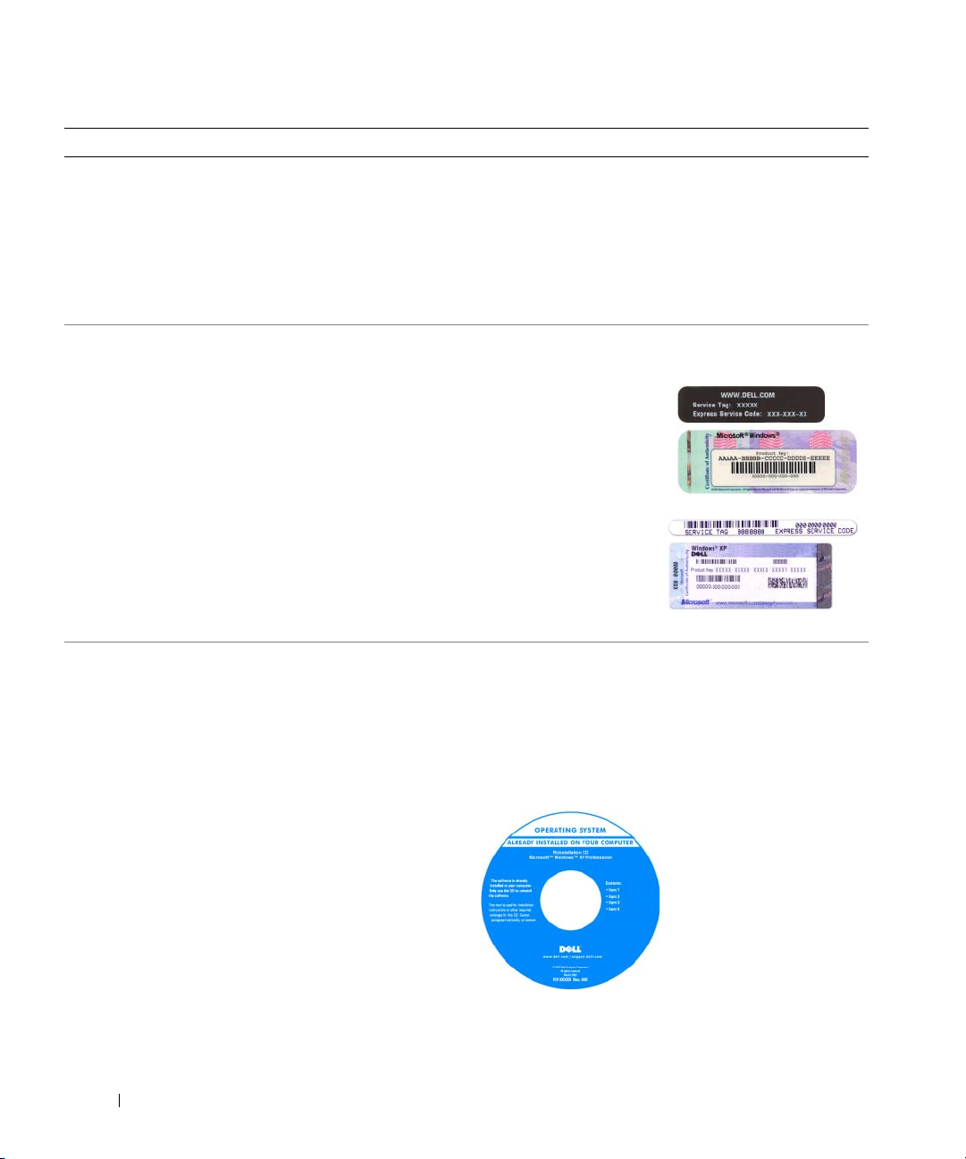
• Service Tag and Express Service Code
• Microsoft Windows License Label
Dell™ OptiPlex™ User’s Guide
Microsoft Windows XP Help and Support Center
1
Click
Start→
Guides
2
Click the
The User’s Guide is also available on the optional Drivers
and Utilities CD.
Service Tag and Microsoft® Windows® License
These labels are located on your computer.
• Use the Service Tag to
identify your computer
when you use
support.dell.com
contact support.
• Enter the Express
Service Code to direct
your call when
contacting support.
Help and Support→ Dell User and System
→ System Guides
User’s Guide
.
for your computer.
or
• How to reinstall my operating system
6 Quick Reference Guide
Operating System CD
NOTE: The Operating System CD may be optional and may
not ship with your computer.
The operating system is already installed on your computer.
To reinstall your operating system, use the Operating
System CD. See "Reinstalling Microsoft Windows XP" on
page 39.
After you reinstall your
operating system, you can
use the optional Drivers
and Utilities CD
(ResourceCD) to reinstall
drivers for the devices that
came with your computer.
Your operating system
product key label is located
on your computer.
NOTE: The color of your CD varies based on the operating
system you ordered.
Page 7

What Are You Looking For? Find It Here
• Solutions — Troubleshooting hints and tips, articles from
technicians, frequently asked questions, and online
courses
Dell Support Website — support.dell.com
NOTE: Select your region or business segment to view the
appropriate support site.
• Community — Online discussion with other Dell
customers
• Upgrades — Upgrade information for components, such
as memory, the hard drive, and the operating system
• Customer Care — Contact information, service call and
order status, warranty, and repair information
• Service and support — Service call status and support
history, service contract, online discussions with technical
support
• Reference — Computer documentation, details on my
computer configuration, product specifications, and white
papers
• Downloads — Certified drivers, patches, and software
updates
• Desktop System Software (DSS) — If you reinstall the
operating system for your computer, you should also
reinstall the DSS utility. DSS provides critical updates for
your operating system and support for Dell™ 3.5-inch
USB floppy drives, Intel
®
processors, optical drives, and
USB devices. DSS is necessary for correct operation of
your Dell computer. The software automatically detects
your computer and operating system and installs the
updates appropriate for your configuration.
• How to use Windows XP
• How to work with programs and files
• How to personalize my desktop
To download Desktop System Software:
1
Go to
support.dell.com
segment, and enter your Service Tag.
2
Select
3
Click your operating system and search for the keyword
Desktop System Software
NOTE: The support.dell.com user interface may vary
dependent upon your selections.
Windows Help and Support Center
1
Click
Start→
2
Type a word or phrase that describes your problem and
click the arrow icon.
3
Click the topic that describes your problem.
4
Follow the instructions on the screen.
, select your region or business
Drivers & Downloads
.
Help and Support
and click Go.
.
Quick Reference Guide 7
Page 8
Setting Up Your Computer
CAUTION: Before performing any of the procedures in this section, follow the safety instructions in Product
Information Guide.
NOTICE: If your computer has an expansion card installed (such as a modem card), connect the appropriate cable
to the card, not to the connector on the back panel.
NOTICE: To help allow the computer to maintain proper operating temperature, ensure that you do not place the
computer too close to a wall or other storage compartment that might prevent air circulation around the chassis.
NOTE: Before you install any devices or software that did not ship with your computer, read the documentation
that came with the device or software, or contact the vendor to verify that the device or software is compatible
with your computer and operating system.
You must complete all the steps to properly set up your computer. See the appropriate figures that follow
the instructions.
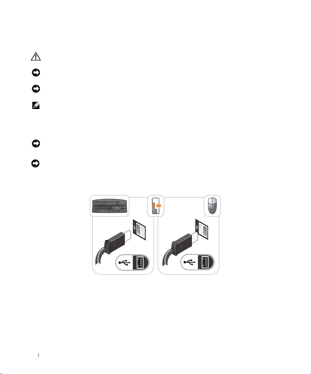
NOTICE: Do not attempt to operate a PS/2 mouse and a USB mouse simultaneously.
1
Connect the keyboard and mouse.
NOTICE: Do not connect a modem cable to the network adapter connector. Voltage from telephone
communications can cause damage to the network adapter.
Set Up Your Keyboard and Mouse
2
Connect the modem or network cable.
Insert the network cable, not the telephone line, into the network connector. If you have an optional
modem, connect the telephone line to the modem.
8 Quick Reference Guide
Page 9
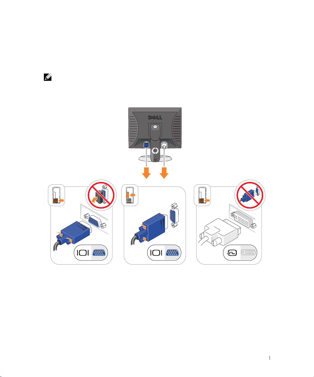
3
Connect the monitor using
either
the white DVI cable or the blue VGA cable (
do not
connect both
cables).
Align and gently insert the monitor cable to avoid bending connector pins. Tighten the thumbscrews
on the cable connectors.
NOTE: Some monitors have the video connector underneath the back of the screen. See the documentation
that came with your monitor for its connector locations.
Set Up Your Monitor
4
Connect the speakers.
5
Connect power cables to the computer, monitor, and devices and connect the other ends of the power
cables to electrical outlets.
Quick Reference Guide 9
Page 10
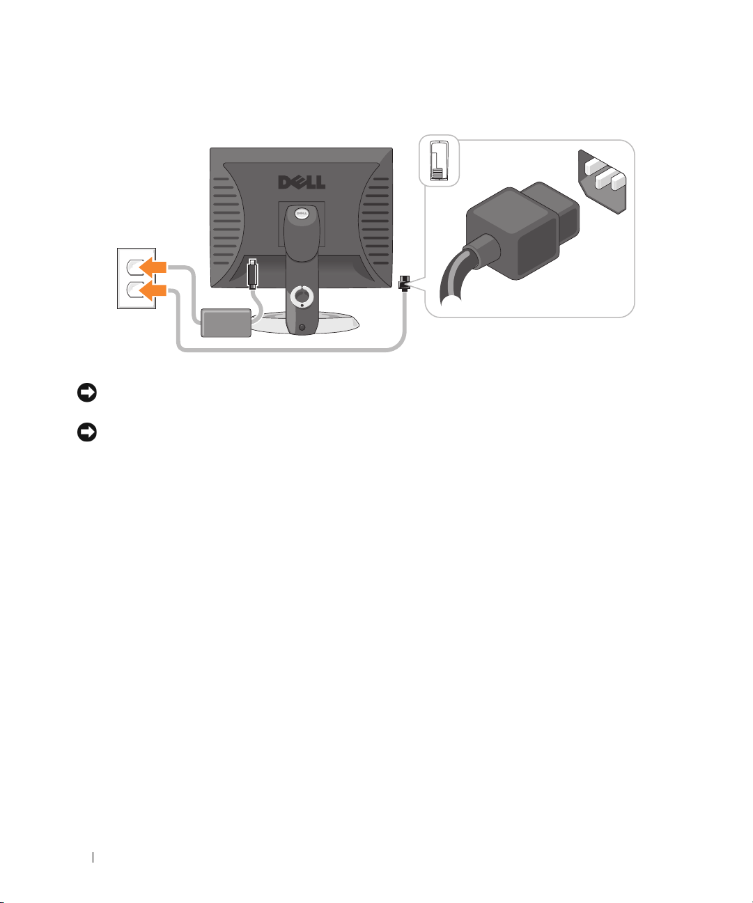
Power Connections
NOTICE: To avoid damaging a computer with a manual voltage-selection switch, set the switch for the voltage that
most closely matches the AC power available in your location.
NOTICE: In Japan, the voltage selection switch must be set to the 115-V position even though the AC power
available in Japan is 100 V.
6
Verify that the voltage selection switch is set correctly for your location.
Your computer has a manual voltage-selection switch. Computers with a voltage selection switch on
the back panel must be manually set to operate at the correct operating voltage.
10 Quick Reference Guide
Page 11
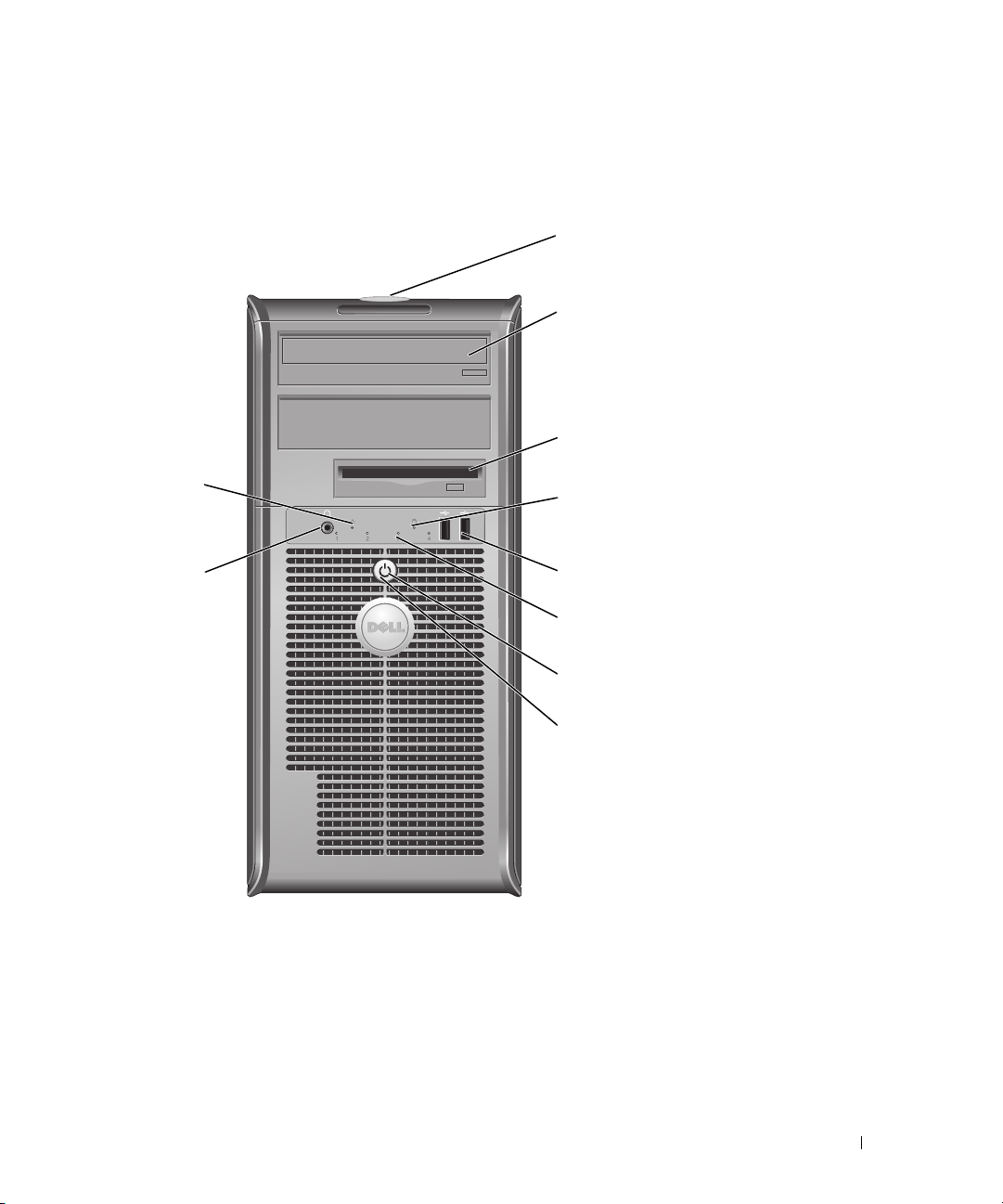
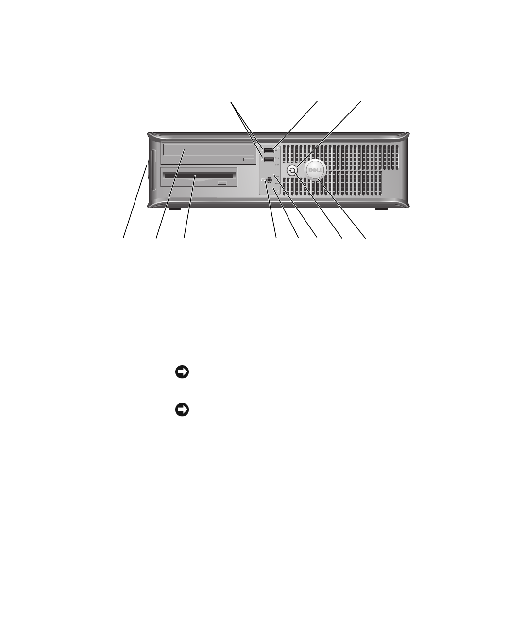
System Views
Mini Tower Computer — Front View
1
2
3
10
9
1 location of Service Tag Use the Service Tag to identify your computer when you access the Dell Support
website or call technical support.
2 CD/DVD drive Insert a CD or DVD (if supported) into this drive.
3 floppy drive Insert a floppy disk into this drive.
4 hard-drive activity light This light flickers when the hard drive is in use.
4
5
6
7
8
Quick Reference Guide 11
Page 12

5 USB 2.0 connectors (2) Use the USB connectors on the front of the computer for devices that you connect
occasionally, such as joysticks or cameras, or for bootable USB devices.
It is recommended that you use the USB connectors on the back of the computer
for devices that typically remain connected, such as printers and keyboards.
6 diagnostic lights Use the lights to help you troubleshoot a computer problem based on the
diagnostic code (for more information, see "Diagnostic Lights" on page 34).
7 power button Press this button to turn on the computer.
NOTICE: To avoid losing data, do not turn off the computer by pressing the
power button. Instead, perform an operating system shutdown.
NOTICE: If your operating system has ACPI enabled, when you press the power
button the computer will perform an operating system shutdown.
8 power light The power light illuminates and blinks or remains solid to indicate different
operating states:
• No light — The computer is turned off.
• Steady green — The computer is in a normal operating state.
• Blinking green — The computer is in a power-saving mode.
• Blinking or solid amber — The computer is receiving electrical power, but an
internal power problem might exist. See "Power Problems" in your online
Guide
.
To exit from a power-saving mode, press the power button or use the keyboard or
the mouse if it is configured as a wake device in the Windows Device Manager. For
more information about sleep modes and exiting from a power-saving mode, see
your online User’s Guide.
For a description of light codes that can help you troubleshoot problems with your
computer, see "System Lights" on page 33.
9 headphone connector Use the headphone connector to attach headphones.
10 link integrity light
• Green — A good connection exists between a 10-Mbps network and the computer.
• Orange — A good connection exists between a 100-Mbps network and the
computer.
• Off — The computer is not detecting a physical connection to the network.
User’s
12 Quick Reference Guide
Page 13
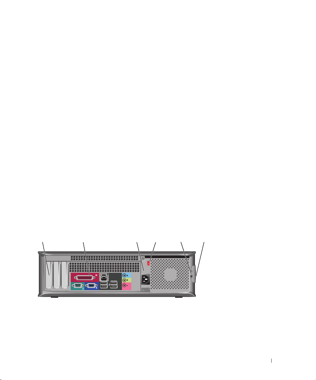
Mini Tower Computer — Back View
1
2
3
4
5
6
1
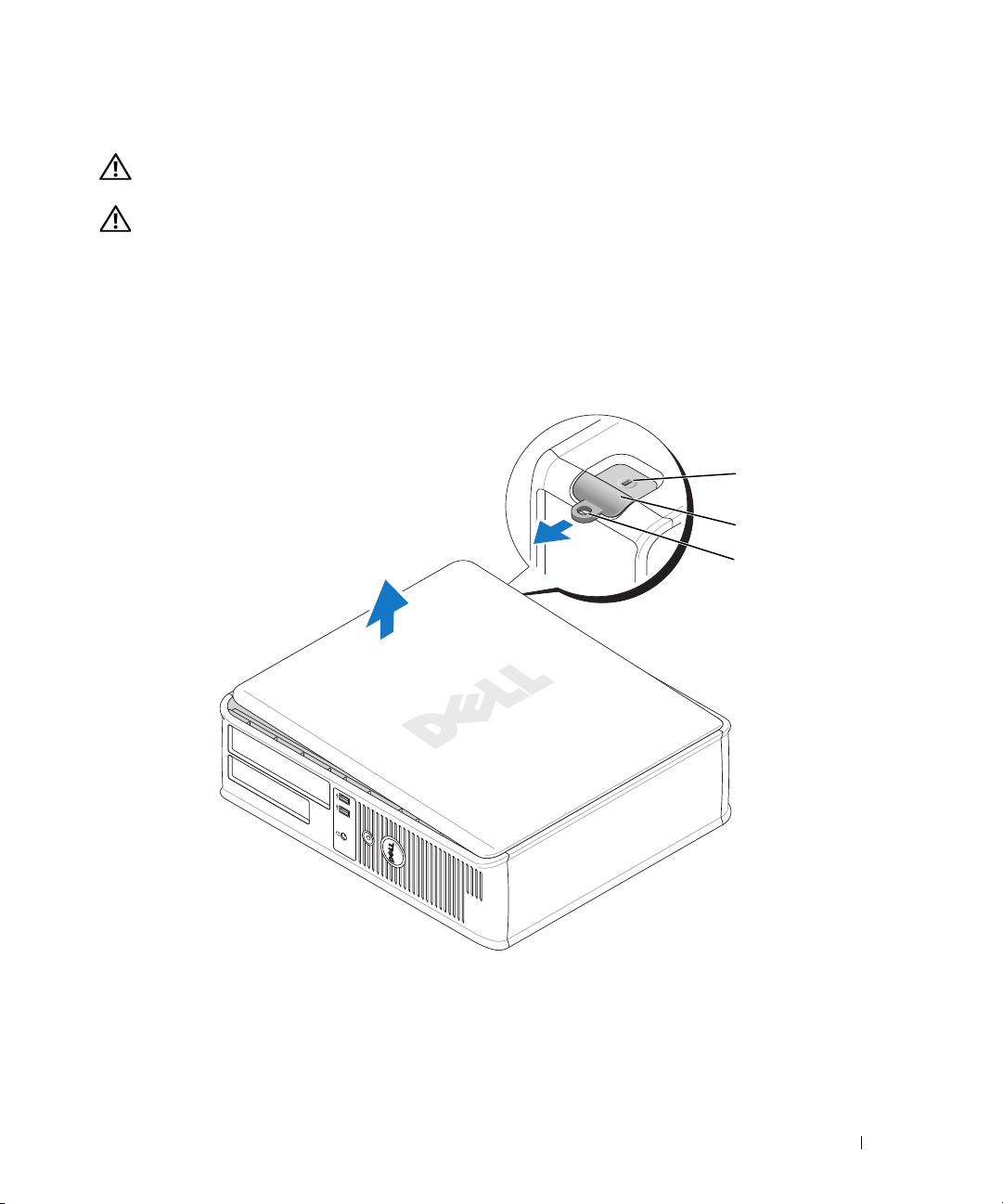
cover release latch
padlock ring
2
3 power connector Insert the power cable into this connector.
This latch allows you to open the computer cover.
Insert a padlock to lock the computer cover.
Quick Reference Guide 13
Page 14
4 voltage selection switch Your computer is equipped with a manual voltage-selection switch. To avoid
damaging a computer with a manual voltage-selection switch, set the switch for the
voltage that most closely matches the AC power available in your location.
NOTICE: In Japan the voltage-selection switch must be set to the 115-V
position.
Also, ensure that your monitor and attached devices are electrically rated to operate
with the AC power available in your location.
5 back-panel connectors Plug serial, USB, and other devices into the appropriate connector.
See "Mini Tower Computer — Back-Panel Connectors" on page 14.
6 card slots Access connectors for any installed PCI and PCI Express cards.
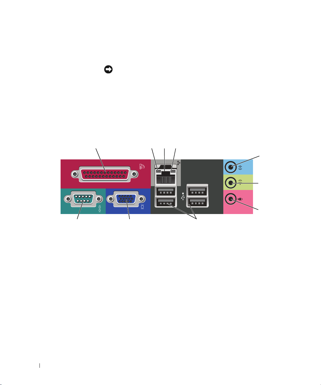
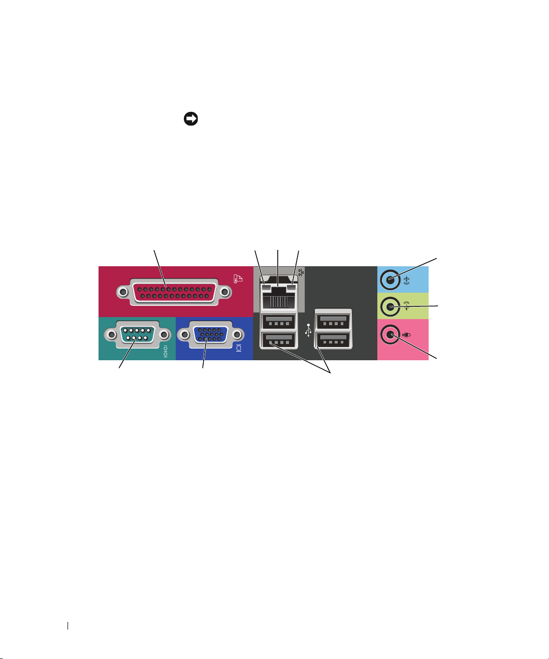
Mini Tower Computer — Back-Panel Connectors
1
parallel connector
13
10 9 8
Connect a parallel device, such as a printer, to the parallel connector. If you have a
USB printer, plug it into a USB connector.
24
NOTE: The integrated parallel connector is automatically disabled if the computer
detects an installed card containing a parallel connector configured to the same
address. For more information, see your online User’s Guide.
link integrity light • Green — A good connection exists between a 10-Mbps network and the
2
computer.
• Orange — A good connection exists between a 100-Mbps network and the
computer.
• Off — The computer is not detecting a physical connection to the network.
5
6
7
14 Quick Reference Guide
Page 15

3
network adapter
connector
network activity light
4
line-in connector
5
line-out connector
6
microphone connector
7
USB 2.0 connectors (4)
8
9
video connector
serial connector
10
To attach your computer to a network or broadband device, connect one end of a
network cable to a network jack or your network or broadband device. Connect the
other end of the network cable to the network adapter connector on the back
panel of your computer. A click indicates that the network cable has been securely
attached.
NOTE: Do not plug a telephone cable into the network connector.
On computers with a network adapter card, use the connector on the card.
It is recommended that you use Category 5 wiring and connectors for your
network. If you must use Category 3 wiring, force the network speed to 10 Mbps
to ensure reliable operation.
This light flashes yellow when the computer is transmitting or receiving network
data. A high volume of network traffic may make this light appear to be in a steady
"on" state.
Use the blue line-in connector to attach a record/playback device such as a
cassette player, CD player, or VCR.
On computers with a sound card, use the connector on the card.
Use the green line-out connector to attach headphones and most speakers with
integrated amplifiers.
On computers with a sound card, use the connector on the card.
Use the pink microphone connector to attach a personal computer microphone
for voice or musical input into a sound or telephony program.
On computers with a sound card, the microphone connector is on the card.
Use the back USB connectors for devices that typically remain connected, such as
printers and keyboards.
Plug the cable from your VGA-compatible monitor into the blue connector.
NOTE: If you purchased an optional graphics card, this connector will be covered by
a cap. Connect your monitor to the connector on the graphics card. Do not remove
the cap.
Connect a serial device, such as a handheld device, to the serial port. The default
designation is COM1 for serial connector 1.
For more information, see your online User’s Guide.
Quick Reference Guide 15
Page 16
Desktop Computer — Front View
1
11
1 USB 2.0 connectors (2) Use the USB connectors on the front of the computer for devices that you
connect occasionally, such as joysticks or cameras, or for bootable USB devices
(see your online User’s Guide for more information about booting to a USB
device).
It is recommended that you use the USB connectors on the back panel for devices
that typically remain connected, such as printers and keyboards.
2 hard-drive activity light This light flickers when the hard drive is being accessed.
3 power button Press this button to turn on the computer.
NOTICE: To avoid losing data, do not turn off the computer by pressing the
power button for 6 seconds or longer. Instead, perform an operating system
shutdown.
89
2
7
3
5
4610
NOTICE: If your operating system has ACPI enabled, when you press the
power button the computer will perform an operating system shutdown.
4 Dell badge This badge can be rotated to match the orientation of your computer. To rotate
the badge, place your fingers around the outside of the badge, press firmly, and
turn the badge. You can also rotate the badge using the slot provided near the
bottom of the badge.
16 Quick Reference Guide
Page 17
5 power light The power light illuminates and blinks or remains solid to indicate different
operating states:
• No light — The computer is turned off.
• Steady green — The computer is in a normal operating state.
• Blinking green — The computer is in a power-saving mode.
• Blinking or solid amber — See "Power Problems" in your online
To exit from a power-saving mode, press the power button or use the keyboard or
the mouse if it is configured as a wake device in the Windows Device Manager.
For a description of light codes that can help you troubleshoot problems with your
computer see "System Lights" on page 33.
6 diagnostic lights Use the lights to help you troubleshoot a computer problem based on the
diagnostic code. For more information, see "Diagnostic Lights" on page 34.
7 link integrity light
8 headphone connector Use the headphone connector to attach headphones.
9 floppy drive Insert a floppy disk into this drive.
10 CD/DVD drive Insert a CD or DVD (if supported) into this drive.
11 location of Service Tag Use the Service Tag to identify your computer when you access the Dell Support
• Green — A good connection exists between a 10-Mbps network and the
computer.
• Orange — A good connection exists between a 100-Mbps network and the
computer.
• Off — The computer is not detecting a physical connection to the network.
website or call technical support.
User’s Guide
.
Desktop Computer — Back View
1
1 card slots Access connectors for any installed PCI and PCI Express Cards.
2 back-panel connectors Plug serial, USB, and other devices into the appropriate connector.
3 power connector Insert the power cable into this connector.
2 3 4 6
See "Desktop Computer — Back-Panel Connectors" on page 18.
5
Quick Reference Guide 17
Page 18
4 voltage selection switch Your computer is equipped with a manual voltage-selection switch. To avoid
damaging a computer with a manual voltage-selection switch, set the switch for
the voltage that most closely matches the AC power available in your location.
NOTICE: In Japan, the voltage-selection switch must be set to the 115-V
position.
Also, ensure that your monitor and attached devices are electrically rated to
operate with the AC power available in your location.
5 padlock ring Insert a padlock to lock the computer cover.
6 cover release latch Use this latch to open the computer cover.
Desktop Computer — Back-Panel Connectors
1
parallel connector
13
10 9 8
Connect a parallel device, such as a printer, to the parallel connector. If you have a
USB printer, plug it into a USB connector.
24
NOTE: The integrated parallel connector is automatically disabled if the computer
detects an installed card containing a parallel connector configured to the same
address. For more information, see your online User’s Guide.
link integrity light • Green — A good connection exists between a 10-Mbps network and the
2
computer.
• Orange — A good connection exists between a 100-Mbps network and the
computer.
• Off — The computer is not detecting a physical connection to the network.
5
6
7
18 Quick Reference Guide
Page 19

3
network adapter
connector
network activity light
4
line-in connector
5
line-out connector
6
microphone connector
7
USB 2.0 connectors (4)
8
9
video connector
serial connector
10
To attach your computer to a network or broadband device, connect one end of a
network cable to either a network jack or your network or broadband device.
Connect the other end of the network cable to the network adapter connector on
the back panel of your computer. A click indicates that the network cable has been
securely attached.
NOTE: Do not plug a telephone cable into the network connector.
On computers with a network adapter card, use the connector on the card.
It is recommended that you use Category 5 wiring and connectors for your
network. If you must use Category 3 wiring, force the network speed to 10 Mbps
to ensure reliable operation.
This light flashes yellow when the computer is transmitting or receiving network
data. A high volume of network traffic may make this light appear to be in a steady
"on" state.
Use the blue line-in connector to attach a record/playback device such as a
cassette player, CD player, or VCR.
On computers with a sound card, use the connector on the card.
Use the green line-out connector to attach headphones and most speakers with
integrated amplifiers.
On computers with a sound card, use the connector on the card.
Use the pink microphone connector to attach a personal computer microphone
for voice or musical input into a sound or telephony program.
On computers with a sound card, the microphone connector is on the card.
Use the back USB connectors for devices that typically remain connected, such as
printers and keyboards.
Plug the cable from your VGA-compatible monitor into the blue connector.
NOTE: If you purchased an optional graphics card, this connector will be covered by
a cap. Connect your monitor to the connector on the graphics card. Do not remove
the cap.
Connect a serial device, such as a handheld device, to the serial port. The default
designation is COM1 for serial connector 1.
For more information, see your online User’s Guide.
Quick Reference Guide 19
Page 20

Removing the Computer Cover
CAUTION: Before you begin any of the procedures in this section, follow the safety instructions in the Product
Information Guide.
CAUTION: To guard against electrical shock, always unplug your computer from the electrical outlet before
removing the cover.
Before You Begin
NOTICE: To avoid losing data, save and close any open files and exit any open programs before you turn off your
computer.
1
Shut down the operating system:
a
Save and close any open files, exit any open programs, click the
Off Computer
b
In the
Turn off computer
.
window, click
Tur n o ff
.
The computer turns off after the operating system shutdown process finishes.
2
Ensure that the computer and any attached devices are turned off. If your computer and attached
devices did not automatically turn off when you shut down your operating system, turn them off now.
Before Working Inside Your Computer
Use the following safety guidelines to help protect your computer from potential damage and to help
ensure your own personal safety.
CAUTION: Before you begin any of the procedures in this section, follow the safety instructions in the Product
Information Guide.
Start
button, and then click
Tu r n
CAUTION: Handle components and cards with care. Do not touch the components or contacts on a card. Hold a
card by its edges or by its metal mounting bracket. Hold a component such as a processor by its edges, not by
its pins.
NOTICE: Only a certified service technician should perform repairs on your computer. Damage due to servicing
that is not authorized by Dell is not covered by your warranty.
NOTICE: When you disconnect a cable, pull on its connector or on its strain-relief loop, not on the cable itself.
Some cables have a connector with locking tabs; if you are disconnecting this type of cable, press in on the locking
tabs before you disconnect the cable. As you pull connectors apart, keep them evenly aligned to avoid bending any
connector pins. Also, before you connect a cable, ensure that both connectors are correctly oriented and aligned.
To avoid damaging the computer, perform the following steps before you begin working inside the
computer.
1
Turn off your computer.
NOTICE: To disconnect a network cable, first unplug the cable from your computer and then unplug it from the
network wall jack.
2
Disconnect any telephone or telecommunication lines from the computer.
20 Quick Reference Guide
Page 21

3
Disconnect your computer and all attached devices from their electrical outlets, and then press the
power button to ground the system board.
4
If applicable, remove the computer stand (for instructions, see the documentation that came with the
stand).
CAUTION: To guard against electrical shock, always unplug your computer from the electrical outlet before
removing the cover.
5
Remove the computer cover:
• Remove the mini tower computer cover (see "Mini Tower Computer" on page 21).
• Remove the desktop computer cover (see "Desktop Computer" on page 27).
NOTICE: Before touching anything inside your computer, ground yourself by touching an unpainted metal surface,
such as the metal at the back of the computer. While you work, periodically touch an unpainted metal surface to
dissipate any static electricity that could harm internal components.
Mini Tower Computer
CAUTION: Before you begin any of the procedures in this section, follow the safety instructions in the Product
Information Guide.
CAUTION: To guard against electrical shock, always unplug your computer from the electrical outlet before
removing the computer cover.
1
Follow the procedures in "Before You Begin" on page 20.
2
If you have installed a padlock through the padlock ring on the back panel, remove the padlock.
3
Lay the computer on its side.
4
Slide the cover release latch back as you lift the cover.
5
Grip the sides of the computer cover and pivot the cover up using the hinge tabs as leverage points.
6
Remove the cover from the hinge tabs and set it aside on a soft nonabrasive surface.
Quick Reference Guide 21
Page 22
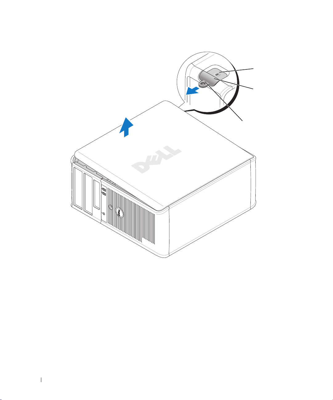
1
2
3
22 Quick Reference Guide
1 security cable slot
2 cover release latch
3 padlock ring
Page 23
Desktop Computer
CAUTION: Before you begin any of the procedures in this section, follow the safety instructions in the Product
Information Guide.
CAUTION: To guard against electrical shock, always unplug your computer from the electrical outlet before
removing the computer cover.
1
Follow the procedures in "Before You Begin" on page 20.
2
If you have installed a padlock through the padlock ring on the back panel, remove the padlock.
3
Slide the cover release latch back as you lift the cover.
4
Pivot the cover up using the hinge tabs as leverage points.
5
Remove the cover from the hinge tabs and set it aside on a soft nonabrasive surface.
1
2
3
1
security cable slot
2
cover release latch
3
padlock ring
Quick Reference Guide 23
Page 24

Inside Your Computer
Mini Tower Computer
2
1
3
4
5
1 CD/DVD drive 4 system board
2 floppy drive 5 heat sink assembly
3 power supply 6 hard drive
24 Quick Reference Guide
6
Page 25

System Board Components
12
17
16
15
14
3
4
5
6
7
13
12
10
911
8
Quick Reference Guide 25
Page 26
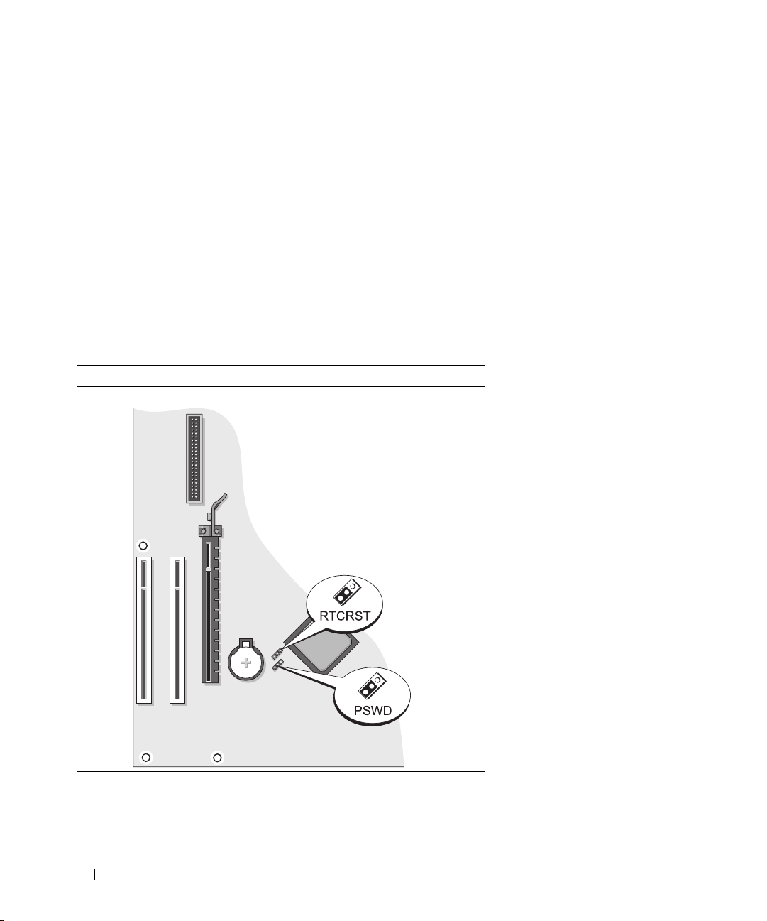
1 fan connector (FAN) 10 internal buzzer (SPKR1)
2 processor connector (CPU) 11 password jumper (PSWD)
3 processor power connector (12VPOWER) 12 real time clock reset jumper (RTCRST)
4 front-panel connector (FNT_PANEL) 13 battery socket (BATT)
5 memory module connectors (DIMM_1,
DIMM_2)
6 SATA drive connectors (SATA0, SATA1) 15 PCI card connectors (2)
7 power connector (POWER) 16 floppy drive connector (FLOPPY)
8 CD/DVD drive connector (IDE) 17 serial/ PS/2 connector (PS2/SER2)
9 SATA drive connectors (SATA2, SATA3)
14 PCI Express x16 card connector
Jumper Settings
Mini Tower Computer
26 Quick Reference Guide
Page 27

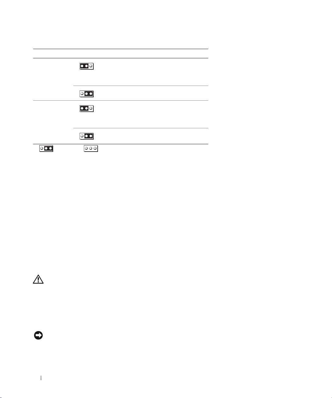
Jumper Setting Description
PSWD Password features are enabled
(default setting).
1
Password features are disabled.
RTCRST
jumpered unjumpered
Desktop Computer
The real-time clock has been
enabled (default setting).
1
The real-time clock is being reset
(jumpered temporarily).
2
1
3
4
6
1 drive bay (CD/DVD, floppy,
and hard drive)
2 power supply 5 heat sink assembly
3 system board 6 front I/O panel
4 card slots
5
Quick Reference Guide 27
Page 28
System Board Components
12
17
16
15
14
3
4
5
6
13
12
28 Quick Reference Guide
11 9
10
7
8
Page 29

1 fan connector (FAN) 10 internal buzzer (SPKR1)
2 processor connector (CPU) 11 password jumper (PSWD)
3 processor power connector (12VPOWER) 12 RTC reset jumper (RTCRST)
4 front-panel connector (FNT_PANEL) 13 battery socket (BATT)
5 memory module connectors (DIMM_1, DIMM_2) 14 PCI Express x16 card connector
6 serial ATA drive connectors (SATA0, SATA1) 15 PCI card connector (2)
7 power connector (POWER) 16 floppy drive connector (FLOPPY)
8 CD/DVD drive connector (IDE) 17 serial/ PS/2 connector (PS2/SER2)
9 serial ATA drive connectors (SATA2, SATA3)
Jumper Settings
Desktop Computer
Quick Reference Guide 29
Page 30
Jumper Setting Description
PSWD Password features are enabled
1
(default setting).
Password features are disabled.
RTCRST
1
jumpered unjumpered
The real-time clock has been
enabled (default setting).
The real-time clock is being reset
(jumpered temporarily).
Solving Problems
Dell provides a number of tools to help you if your computer does not perform as expected. For the latest
troubleshooting information available for your computer, see the Dell Support website at
support.dell.com.
If computer problems occur that require help from Dell, write a detailed description of the error, beep
codes, or diagnostics light patterns, record your Express Service Code and Service Tag below, and then
contact Dell from the same location as your computer. For information on contacting Dell, see your
online User’s Guide.
For an example of the Express Service Code and Service Tag, see "Finding Information" on page 5.
Express Service Code: ___________________________
Service Tag: ___________________________
Dell Diagnostics
CAUTION: Before you begin any of the procedures in this section, follow the safety instructions in the Product
Information Guide.
When to Use the Dell Diagnostics
If you experience a problem with your computer, perform the checks in "Solving Problems" in your online
User’s Guide and run the Dell Diagnostics before you contact Dell for technical assistance. For
information on contacting Dell, see your online User’s Guide.
NOTICE: The Dell Diagnostics works only on Dell™ computers.
30 Quick Reference Guide
Page 31

Enter system setup (see "System Setup" in your online User’s Guide for instructions), review your
computer’s configuration information, and ensure that the device you want to test displays in system
setup and is active.
Start the Dell Diagnostics from either your hard drive or from the optional Drivers and Utilities CD (also
known as the ResourceCD).
Starting the Dell Diagnostics From Your Hard Drive
1
Turn on (or restart) your computer.
2
When the DELL logo appears, press <F12> immediately.
NOTE: If you see a message stating that no diagnostics utility partition has been found, run the Dell
Diagnostics from the optional Drivers and Utilities CD (see "Starting the Dell Diagnostics From the Drivers and
Utilities CD" on page 31).
If you wait too long and the operating system logo appears, continue to wait until you see the
Microsoft
3
When the boot device list appears, highlight
4
When the Dell Diagnostics
Starting the Dell Diagnostics From the Drivers and Utilities CD
1
Insert the
2
Shut down and restart the computer.
®
Windows® desktop. Then shut down your computer and try again.
Main Menu
Drivers and Utilities
Boot to Utility Partition
appears, select the test you want to run.
CD.
and press <Enter>.
When the DELL logo appears, press <F12> immediately.
If you wait too long and the operating system logo appears, continue to wait until you see the
Microsoft Windows desktop. Then shut down your computer and try again.
NOTE: The next steps change the boot sequence for one time only. On the next start-up, the computer boots
according to the devices specified in system setup.
3
When the boot device list appears, highlight the listing for the CD/DVD drive and press <Enter>.
4
Select the listing for the CD/DVD drive option from the CD boot menu.
5
Select the option to boot from the CD/DVD drive from the menu that appears.
6
Ty p e 1 to start the
7
Ty p e 2 to start the Dell Diagnostics.
8
Select
Run the 32 Bit Dell Diagnostics
Drivers and Utilities
CD menu.
from the numbered list. If multiple versions are listed, select
the version appropriate for your computer.
9
When the Dell Diagnostics
Main Menu
appears, select the test you want to run.
Quick Reference Guide 31
Page 32

Dell Diagnostics Main Menu
1
After the Dell Diagnostics loads and the
Main Menu
screen appears, click the button for the option
you want.
Option Function
Express Test Performs a quick test of devices. This test typically takes 10 to 20 minutes and requires
no interaction on your part. Run Express Test first to increase the possibility of tracing
the problem quickly.
Extended Test Performs a thorough check of devices. This test typically takes an hour or more and
requires you to answer questions periodically.
Custom Test Tests a specific device. You can customize the tests you want to run.
Symptom Tree Lists the most common symptoms encountered and allows you to select a test based on
the symptom of the problem you are having.
2
If a problem is encountered during a test, a message appears with an error code and a description of the
problem. Write down the error code and problem description and follow the instructions on the
screen.
If you cannot resolve the error condition, contact Dell. For information on contacting Dell, see your
online
User’s Guide
NOTE: The Service Tag for your computer is located at the top of each test screen. If you contact Dell,
technical support will ask for your Service Tag.
3
If you run a test from the
.
Custom Test
or
Symptom Tree
option, click the applicable tab described in
the following table for more information.
Tab Function
Results Displays the results of the test and any error conditions encountered.
Errors Displays error conditions encountered, error codes, and the problem description.
Help Describes the test and may indicate requirements for running the test.
Configuration Displays your hardware configuration for the selected device.
The Dell Diagnostics obtains configuration information for all devices from system
setup, memory, and various internal tests, and it displays the information in the device
list in the left pane of the screen. The device list may not display the names of all the
components installed on your computer or all devices attached to your computer.
Parameters You can customize the test by changing the test settings.
4
When the tests are completed, if you are running the Dell Diagnostics from the
Drivers and Utilities
CD (optional), remove the CD.
5
Close the test screen to return to the
computer, close the
Main Menu
Main Menu
screen.
screen. To exit the Dell Diagnostics and restart the
32 Quick Reference Guide
Page 33

System Lights
Your power light may indicate a computer problem.
Power Light Problem Description Suggested Resolution
Solid green Power is on, and the computer is
operating normally.
Blinking green The computer is in a power-saving
mode.
Blinks green several
times and then turns off
Solid yellow The Dell Diagnostics is running a
Blinking yellow A power supply or system board
Solid green and a beep
code during POST
Solid green power light,
no beep code and no
video during POST
Solid green power light
and no beep code, but
the computer locks up
during POST
A configuration error exists. Check Diagnostic Lights to see if the specific
test, or a device on the system board
may be faulty or incorrectly installed.
failure has occurred.
A problem was detected while the
BIOS was executing.
The monitor or the graphics card may
be faulty or incorrectly installed.
An integrated system board device
may be faulty.
No corrective action is required.
Press the power button, move the mouse, or
press a key on the keyboard to wake the
computer.
problem is identified (see "Diagnostic Lights"
on page 34).
If the Dell Diagnostics is running, allow the
testing to complete.
Check Diagnostic Lights to see if the specific
problem is identified (see "Diagnostic Lights"
on page 34).
If the computer does not boot, contact Dell
for technical assistance.
contacting Dell, see your online
Check Diagnostic Lights to see if the specific
problem is identified (see "Diagnostic Lights"
on page 34).
See "Power Problems" in your online User’s
Guide.
For instructions on diagnosing the beep code
see "Beep Codes" on page 37. Also, check
Diagnostic Lights to see if the specific
problem is identified.
Check Diagnostic Lights to see if the specific
problem is identified.
Check Diagnostic Lights to see if the specific
problem is identified. If the problem is not
identified, contact Dell for technical
assistance.
see your online
For information on contacting Dell,
User’s Guide
For information on
User’s Guide
.
.
Quick Reference Guide 33
Page 34

Diagnostic Lights
CAUTION: Before you begin any of the procedures in this section, follow the safety instructions in the Product
Information Guide.
To help you troubleshoot a problem, your computer has four lights labeled "1," "2," "3," and "4" on the
front or back panel. The lights can be "off" or green. When the computer starts normally, the patterns or
codes on the lights change as the boot process completes. If the POST portion of system boot completes
successfully, all four lights display solid green for a short time, and then turn off.
If the computer malfunctions during the POST process, the pattern displayed on the LEDs may help
identify where in the process the computer halted. If the computer malfunctions after a successful
POST, the diagnostic lights do not indicate the cause of the problem.
NOTE: The orientation of the diagnostic lights may vary depending on the system type. The diagnostic lights can be
either vertically or horizontally oriented.
Light Pattern Problem Description Suggested Resolution
The computer is in a normal "off"
condition, or a possible pre-BIOS failure
has occurred.
The diagnostic lights are not lit after the
computer successfully boots to the
operating system.
A possible BIOS failure has occurred; the
computer is in recovery mode.
A possible processor failure has occurred. Reinstall the processor and restart the
Plug the computer into a working electrical
outlet and press the power button.
Run the BIOS Recovery utility, wait for
recovery completion, and then restart the
computer.
computer.
processor, see your online
For information on reinstalling the
User’s Guide
.
34 Quick Reference Guide
Page 35

Light Pattern Problem Description Suggested Resolution
Memory modules are detected, but a
memory failure has occurred.
A possible graphics card failure has
occurred.
A possible floppy or hard drive failure has
occurred.
• If you have one memory module installed,
reinstall it and restart the computer. For
information on reinstalling memory
modules, see your online
• If you have two or more memory modules
installed, remove the modules, reinstall one
module, and then restart the computer. If
the computer starts normally, reinstall an
additional module. Continue until you have
identified a faulty module or reinstalled all
modules without error.
• If available, install properly working
memory of the same type into your
computer.
• If the problem persists,
information on contacting Dell, see your
User’s Guide
online
• If the computer has a graphics card, remove
the card, reinstall it, and then restart the
computer.
• If the problem still exists, install a graphics
card that you know works and restart the
computer.
• If the problem persists or the computer has
integrated graphics,
information on contacting Dell, see your
online
User’s Guide
Reseat all power and data cables and restart
the computer.
User’s Guide
contact Dell
.
contact Dell
.
.
. For
. For
A possible USB failure has occurred. Reinstall all USB devices, check cable
connections, and then restart the computer.
Quick Reference Guide 35
Page 36

Light Pattern Problem Description Suggested Resolution
No memory modules are detected.
Memory modules are detected, but a
memory configuration or compatibility
error exists.
A failure has occurred.
This pattern also displays when you enter
system setup and may not indicate a
problem.
After POST is complete, all four
diagnostic lights turn green briefly before
turning off to indicate a normal operating
condition.
• If you have one memory module installed,
reinstall it and restart the computer. For
information on reinstalling memory
modules, see your online
• If you have two or more memory modules
installed, remove the modules, reinstall one
module, and then restart the computer. If
the computer starts normally, reinstall an
additional module. Continue until you have
identified a faulty module or reinstalled all
modules without error.
• If available, install properly working
memory of the same type into your
computer.
• If the problem persists,
information on contacting Dell, see your
User’s Guide
online
• Ensure that no
module/memory connector placement
requirements
• Verify that the
are installing are compatible with your
computer.
• If the problem persists,
information on contacting Dell, see your
online
User’s Guide
• Ensure that the cables are properly
connected to the system board from the
hard drive, CD drive, and DVD drive.
• Check the computer message that appears
on your monitor screen.
• If the problem persists,
information on contacting Dell, see your
online
User’s Guide
None.
special memory
exist.
memory modules
User’s Guide
contact Dell
.
contact Dell
.
contact Dell
.
.
. For
that you
. For
. For
36 Quick Reference Guide
Page 37

Beep Codes
Your computer might emit a series of beeps during start-up if the monitor cannot display errors or
problems. This series of beeps, called a beep code, identifies a problem. One possible beep code
(code 1-3-1) consists of one beep, a burst of three beeps, and then one beep. This beep code tells you
that the computer encountered a memory problem.
If your computer beeps during start-up:
1
Write down the beep code.
2
See "Dell Diagnostics" on page 30 to identify a more serious cause.
3
Contact Dell for technical assistance. For information on contacting Dell, see your online
.
Guide
Code Cause Code Cause
1-1-2 Microprocessor register failure 3-1-4 Slave interrupt mask register failure
1-1-3 NVRAM read/write failure 3-2-2 Interrupt vector loading failure
1-1-4 ROM BIOS checksum failure 3-2-4 Keyboard Controller test failure
1-2-1 Programmable interval timer failure 3-3-1 NVRAM power loss
1-2-2 DMA initialization failure 3-3-2 Invalid NVRAM configuration
1-2-3 DMA page register read/write
failure
1-3 Video Memory test failure 3-4-1 Screen initialization failure
1-3-1 through 2-4-4 Memory not being properly
identified or used
3-1-1 Slave DMA register failure 3-4-3 Search for video ROM failure
3-1-2 Master DMA register failure 4-2-1 No timer tick
3-1-3 Master interrupt mask register
failure
4-2-3 Gate A20 failure 4-4-1 Serial or parallel port test failure
4-2-4 Unexpected interrupt in protected
mode
4-3-1 Memory failure above address
0FFFFh
4-3-3 Timer-chip counter 2 failure 4-4-4 Cache test failure
4-3-4 Time-of-day clock stopped
3-3-4 Video Memory test failure
3-4-2 Screen retrace failure
4-2-2 Shutdown failure
4-4-2 Failure to decompress code to
shadowed memory
4-4-3 Math-coprocessor test failure
User’s
Quick Reference Guide 37
Page 38

Resolving Software and Hardware Incompatibilities
If a device is either not detected during the operating system setup or is detected but incorrectly
configured, you can use the Hardware Troubleshooter to resolve the incompatibility.
1
Click the
2
Ty p e
3
Click
4
In the
click
Start
button and click
Help and Support
hardware troubleshooter
Hardware Troubleshooter
Hardware Troubleshooter
Next
.
in the
list, click
.
in the
Search
field and click the arrow to start the search.
Search Results
list.
I need to resolve a hardware conflict on my computer
, and
Using Microsoft Windows XP System Restore
The Microsoft Windows XP operating system provides System Restore to allow you to return your
computer to an earlier operating state (without affecting data files) if changes to the hardware, software,
or other system settings have left the computer in an undesirable operating state. See the Windows Help
and Support Center for information on using System Restore. To access the Windows Help and Support
Center, see "Windows Help and Support Center" on page 7.
NOTICE: Make regular backups of your data files. System Restore does not monitor your data files or recover them.
Creating a Restore Point
1
Click the
2
Click
3
Follow the instructions on the screen.
Start
button and click
System Restore
Help and Support
.
.
Restoring the Computer to an Earlier Operating State
NOTICE: Before you restore the computer to an earlier operating state, save and close any open files and exit any
open programs. Do not alter, open, or delete any files or programs until the system restoration is complete.
1
Click the
Restore
2
Ensure that
3
Click a calendar date to which you want to restore your computer.
The
Start
button, point to
.
Restore my computer to an earlier time
Select a Restore Point
All Programs→
Accessories→
System Tools
is selected, and click
, and then click
Next
.
screen provides a calendar that allows you to see and select restore points.
All calendar dates with available restore points appear in boldface type.
4
Select a restore point and click
Next
.
If a calendar date has only one restore point, then that restore point is automatically selected. If two or
more restore points are available, click the restore point that you prefer.
38 Quick Reference Guide
System
Page 39

5
Click
Next
.
The
Restoration Complete
screen appears after System Restore finishes collecting data and then the
computer restarts.
6
After the computer restarts, click OK.
To change the restore point, you can either repeat the steps using a different restore point, or you can
undo the restoration.
Undoing the Last System Restore
NOTICE: Before you undo the last system restore, save and close all open files and exit any open programs. Do not
alter, open, or delete any files or programs until the system restoration is complete.
1
Click the
Restore
2
Click
3
Click
The
4
After the computer restarts, click OK.
Enabling System Restore
Start
button, point to
.
Undo my last restoration
Next
.
System Restore
screen appears and the computer restarts.
All Programs→ Accessories→ System Tools
and click
Next
.
, and then click
System
If you reinstall Windows XP with less than 200 MB of free hard-disk space available, System Restore is
automatically disabled. To verify that System Restore is enabled:
1
Click the
2
Click
3
Click
4
Click the
5
Ensure that
Start
button and click
Control Panel
Performance and Maintenance
System
.
System Restore
tab.
Turn off System Restore
.
.
is unchecked.
Reinstalling Microsoft Windows XP
Before You Begin
NOTE: The procedures in this document were written for the Windows default view in Windows XP Home Edition,
so the steps will differ if you set your Dell computer to the Windows Classic view or are using Windows XP
Professional.
If you are considering reinstalling the Windows XP operating system to correct a problem with a newly
installed driver, first try using Windows XP Device Driver Rollback.
1
Click the
2
Under
3
Click
Start
button and click
Pick a Category
System
.
Control Pane
, click
Performance and Maintenance
l.
.
Quick Reference Guide 39
Page 40

4
In the
System Properties
5
Click
Device Manager
6
Right-click the device for which the new driver was installed and click
7
Click the
8
Click
Drivers
tab.
Roll Back Driver
window, click the
.
.
Hardware
tab.
Properties
.
If Device Driver Rollback does not resolve the problem, then use System Restore to return your operating
system to the operating state it was in before you installed the new device driver (see "Using Microsoft
Windows XP System Restore" on page 38).
NOTE: The Drivers and Utilities CD contains drivers that were installed during assembly of the computer. Use the
Drivers and Utilities CD to load any required drivers, including the drivers required if your computer has a RAID
controller.
Reinstalling Windows XP
NOTICE: You must use Windows XP Service Pack 1 or later when you reinstall Windows XP.
NOTICE: Before performing the installation, back up all data files on your primary hard drive. For conventional hard
drive configurations, the primary hard drive is the first drive detected by the computer.
To reinstall Windows XP, you need the following items:
•Dell
•Dell
Operating System
CD
Drivers and Utilities
CD
To reinstall Windows XP, perform all the steps in the following sections in the order in which they are
listed.
The reinstallation process can take 1 to 2 hours to complete. After you reinstall the operating system, you
must also reinstall the device drivers, virus protection program, and other software.
NOTICE: The Operating System CD provides options for reinstalling Windows XP. The options can overwrite files
and possibly affect programs installed on your hard drive. Therefore, do not reinstall Windows XP unless a Dell
technical support representative instructs you to do so.
NOTICE: To prevent conflicts with Windows XP, disable any virus protection software installed on your computer
before you reinstall Windows XP. See the documentation that came with the software for instructions.
Booting From the Operating System CD
1
Save and close any open files and exit any open programs.
2
Insert the
3
Restart the computer.
4
Press <F12> immediately after the DELL logo appears.
Operating System
CD. Click
Exit
if the
Install Windows XP
message appears.
If the operating system logo appears, wait until you see the Windows desktop, and then shut down the
computer and try again.
40 Quick Reference Guide
Page 41

5
Press the arrow keys to select
6
When the
Windows XP Setup
1
When the
2
Read the information on the
Press any key to boot from CD
Windows XP Setup
CD-ROM
, and press <Enter>.
message appears, press any key.
screen appears, press <Enter> to select
Microsoft Windows Licensing Agreement
To set up Windows now
screen, and press <F8> to
accept the license agreement.
3
If your computer already has Windows XP installed and you want to recover your current Windows XP
data, type
4
If you want to install a new copy of Windows XP, press <Esc> to select that option.
5
Press <Enter> to select the highlighted partition (recommended), and follow the instructions on the
r
to select the repair option, and remove the CD.
screen.
The
Windows XP Setup
screen appears, and the operating system begins to copy files and install the
devices. The computer automatically restarts multiple times.
NOTE: The time required to complete the setup depends on the size of the hard drive and the speed of your
computer.
NOTICE: Do not press any key when the following message appears: Press any key to boot from
the CD
6
When the
click
7
Enter your name and organization (optional) in the
8
At the
accept the one provided) and a password, and click
9
If the
10
Enter the date, time, and time zone in the
11
If the
12
If you are reinstalling Windows XP Professional and you are prompted to provide further information
.
Regional and Language Options
Next
.
screen appears, select the settings for your location and
Computer Name and Administrator Password
Modem Dialing Information
screen appears, enter the requested information and click
Date and Time Settings
Networking Settings
screen appears, click
Personalize Your Software
screen, and click
window, enter a name for your computer (or
Next
.
Typical
and click
window, and click
Next
.
Next
regarding your network configuration, enter your selections. If you are unsure of your settings, accept
the default selections.
Windows XP installs the operating system components and configures the computer. The computer
automatically restarts.
.
Next
.
Next
.
.
NOTICE: Do not press any key when the following message appears: Press any key to boot from
.
Welcome to Microsoft
screen appears, click
Next
.
How will this computer connect to the Internet?
Skip
.
message appears,
Quick Reference Guide 41
13
14
the CD
When the
When the
click
Page 42

15
When the
16
When the
17
Click
18
Click
19
Reinstall the appropriate drivers with the
20
Reinstall your virus protection software.
21
Reinstall your programs.
NOTE: To reinstall and activate your Microsoft Office or Microsoft Works Suite programs, you need the Product
Key number located on the back of the Microsoft Office or Microsoft Works Suite CD sleeve.
Ready to register with Microsoft?
Who will use this computer?
Next
.
Finish
to complete the setup, and remove the CD.
screen appears, you can enter up to five users.
screen appears, select
Drivers and Utilities
No, not at this time
CD.
and click
Next
Using the Drivers and Utilities CD
To use the Drivers and Utilities CD (also known as the ResourceCD) while you are running the Windows
operating system:
NOTE: To access device drivers and user documentation, you must use the Drivers and Utilities CD while you are
running Windows.
1
Turn on the computer and allow it to boot to the Windows desktop.
2
Insert the
If you are using the
Installation
Drivers and Utilities
Drivers and Utilities
window opens to inform you that the
CD into the CD drive.
CD for the first time on this computer, the
Drivers and Utilities
ResourceCD
CD is about to begin installation.
.
3
Click OK to continue.
To complete the installation, respond to the prompts offered by the installation program.
4
Click
Next
at the
Welcome Dell System Owner
5
Select the appropriate
Drivers for Your Computer
To display a list of device drivers for your computer:
1
Click
My Drivers
Drivers and Utilities
The
then a list of device drivers for your system configuration is displayed on the screen.
2
Click the appropriate driver and follow the instructions to download the driver to your computer.
To view all available drivers for your computer, click Drivers from the Topic drop-down menu.
42 Quick Reference Guide
System Model, Operating System, Device Type,
in the
To pi c
drop-down menu.
CD (optional) scans your computer’s hardware and operating system, and
screen.
and
To pi c
.
Page 43

Index
B
beep codes, 37
C
CDs
operating system, 6
conflicts
software and hardware
incompatibilities, 38
cover
removing, 20
D
Dell Diagnostics, 30
Dell support site, 7
diagnostics
beep codes, 37
Dell Diagnostics, 30
documentation
End User License
Agreement, 5
ergonomics, 5
online, 7
Product Information Guide, 5
regulatory, 5
safety, 5
User’s Guide, 6
warranty, 5
drivers
list of, 42
Drivers and Utilities CD, 5
E
End User License
Agreement, 5
ergonomics information, 5
error messages
beep codes, 37
diagnostic lights, 34
system lights, 33
H
hardware
beep codes, 37
conflicts, 38
Dell Diagnostics, 30
Hardware Troubleshooter, 38
Help and Support Center, 7
help file
Windows Help and Support
Center, 7
I
installing parts
before you begin, 20
L
labels
Microsoft Windows, 6
Service Tag, 6
lights
diagnostic, 34
power, 17
system, 33
M
motherboard. See system
board
O
operating system
reinstalling, 6
reinstalling Windows XP, 39
Operating System CD, 6
P
power
light, 17
power light
diagnosing problems with, 33
problems. See troubleshooting
Product Information Guide, 5
IRQ conflicts, 38
Index 43
Page 44

R
W
regulatory information, 5
reinstalling
Windows XP, 39
S
safety instructions, 5
Service Tag, 6
software
conflicts, 38
support website, 7
system board, 25, 28
System Restore, 38
T
troubleshooting
beep codes, 37
conflicts, 38
Dell Diagnostics, 30
diagnostic lights, 34
Hardware Troubleshooter, 38
Help and Support Center, 7
restore computer to previous
operating state, 38
system lights, 33
warranty information, 5
Windows XP
Hardware Troubleshooter, 38
Help and Support Center, 7
reinstalling, 6, 39
setup, 41
System Restore, 38
U
User’s Guide, 6
44 Index
Page 45

Dell™ OptiPlex™ 320
Guide de référence rapide
Modèles DCSM, DCNE
www.dell.com | support.dell.com
Page 46

Remarques, avis et précautions
REMARQUE : Une REMARQUE fournit des informations importantes qui vous aident à mieux utiliser votre ordinateur.
AVIS : Un AVIS vous avertit d’un risque de dommage matériel ou de perte de données et vous indique comment éviter le
problème.
PRÉCAUTION : Une PRÉCAUTION indique un risque potentiel d'endommagement du matériel, de blessure corporelle
ou de mort.
Si vous avez acheté un ordinateur Dell™ Série n, les références du présent document concernant les systèmes
d'application Microsoft
®
Windows® ne sont pas applicables.
____________________
Les informations de ce document sont sujettes à modification sans préavis.
© 2006 Dell Inc. Tous droits réservés.
La reproduction de ce document, de quelque manière que ce soit, sans l'autorisation écrite de Dell Inc. est strictement interdite.
Marques utilisées dans ce document : Dell, OptiPlex et le logo DELL sont des marques de Dell Inc. ; Microsoft et Windows sont des marques
déposées de Microsoft Corporation ; Intel et Pentium sont des marques déposées d'Intel Corporation.
D'autres marques et noms commerciaux peuvent être utilisés dans ce document pour faire référence aux entités se réclamant de ces marques
et de ces noms ou à leurs produits. Dell Inc. rejette tout intérêt propriétaire dans les marques et les noms commerciaux autres que les siens.
Modèles DCSM, DCNE
Septembre 2006 Réf. KK074 Rév. A01
Page 47

Table des matières
Recherche d'informations . . . . . . . . . . . . . . . . . . . . . . . . . . . . 49
Configuration de votre ordinateur
Vues du système
. . . . . . . . . . . . . . . . . . . . . . . . . . . . . . . . . 55
Ordinateur mini-tour — Vue frontale
Ordinateur mini-tour — Vue arrière
. . . . . . . . . . . . . . . . . . . . . . . . 52
. . . . . . . . . . . . . . . . . . . . 55
. . . . . . . . . . . . . . . . . . . . 57
Ordinateur mini-tour — Connecteurs du panneau arrière
Ordinateur de bureau — Vue frontale
Ordinateur de bureau — Vue arrière
. . . . . . . . . . . . . . . . . . . 60
. . . . . . . . . . . . . . . . . . . . 61
Ordinateur de bureau — Connecteurs du panneau arrière
Retrait du capot de l'ordinateur
Avant de commencer
Ordinateur mini-tour
Ordinateur de bureau
L’intérieur de votre ordinateur
Ordinateur mini-tour
Ordinateur de bureau
Résolution des problèmes
Dell Diagnostics
. . . . . . . . . . . . . . . . . . . . . . . . . . . . . . . 74
Voyants du système
Voyants de diagnostic
Codes sonores
. . . . . . . . . . . . . . . . . . . . . . . . . . . . . . 78
. . . . . . . . . . . . . . . . . . . . . . . . . . . . . . . 81
. . . . . . . . . . . . . . . . . . . . . . . . . 64
. . . . . . . . . . . . . . . . . . . . . . . . . . . . 64
. . . . . . . . . . . . . . . . . . . . . . . . . . . . 65
. . . . . . . . . . . . . . . . . . . . . . . . . . . . 67
. . . . . . . . . . . . . . . . . . . . . . . . . . 68
. . . . . . . . . . . . . . . . . . . . . . . . . . . . 68
. . . . . . . . . . . . . . . . . . . . . . . . . . . . 71
. . . . . . . . . . . . . . . . . . . . . . . . . . . . 74
. . . . . . . . . . . . . . . . . . . . . . . . . . . . . 77
Résolution des incompatibilités logicielles et matérielles
Utilisation de la fonction Restauration du système
Microsoft® Windows® XP
Réinstallation de Microsoft® Windows® XP
. . . . . . . . . . . . . . . . . . . . . . . . . 82
. . . . . . . . . . . . . . . 83
. . . . . . . . . 58
. . . . . . . . 62
. . . . . . . . . 82
Utilisation du CD Drivers and Utilities
. . . . . . . . . . . . . . . . . . . . . . 86
Index . . . . . . . . . . . . . . . . . . . . . . . . . . . . . . . . . . . . . . . . . 87
Table des matières 47
Page 48

48 Table des matières
Page 49

Recherche d'informations
REMARQUE : Certaines fonctionnalités ou supports peuvent être optionnels et ne pas accompagner votre
ordinateur. Certaines fonctionnalités ou supports peuvent ne pas être disponibles dans certains pays.
REMARQUE : Il est possible que des informations supplémentaires soient fournies avec votre ordinateur.
Que recherchez-vous ? Cherchez ici
• Programme de diagnostic pour mon ordinateur
• Pilotes pour mon ordinateur
• Documentation de mon ordinateur
• Documentation concernant mon périphérique
• Logiciel DSS (Desktop System Software)
CD Drivers and Utilities (également appelé CD ResourceCD)
REMARQUE : Le CD Drivers and Utilities peut être optionnel et ne
pas être expédié avec votre ordinateur.
La documentation et les pilotes sont déjà installés sur l'ordinateur.
Vous pouvez utiliser le CD pour réinstaller les pilotes (reportezvous à la section « Réinstallation des pilotes et utilitaires » de votre
Guide d'utilisation en ligne), pour exécuter Dell Diagnosticsics
(reportez-vous à la section « Dell Diagnostics » à la page 74) ou
pour accéder à votre documentation.
Des fichiers « Lisez-moi » peuvent
être inclus sur votre CD afin de
fournir les informations les plus
récentes concernant des
modifications techniques
apportées à votre système ou des
informations de référence
destinées aux techniciens ou aux
utilisateurs expérimentés.
• Informations sur les garanties
• Termes et Conditions (États-Unis uniquement)
• Consignes de sécurité
• Informations sur les réglementations
• Informations relatives à l'ergonomie
• Contrat de licence pour utilisateur final
REMARQUE : Les dernières mises à jour des pilotes et de la
documentation se trouvent à l'adresse support.dell.com.
Guide d'information sur le produit Dell™
Guide de référence rapide 49
Page 50

Que recherchez-vous ? Cherchez ici
• Comment retirer et remplacer des pièces
• Caractéristiques
• Comment configurer les paramètres du système
• Comment déterminer et résoudre des problèmes
Guide d'utilisation du Dell™ OptiPlex™
Centre d'aide et de support Microsoft Windows XP
1
Cliquez sur
du système
2
Cliquez sur le
Le Guide d'utilisation est également disponible sur le CD Drivers
and Utilities en option.
• Numéro de service et code de service express
• Étiquette de licence Microsoft Windows
Numéro de service et licence Microsoft® Windows
Ces étiquettes sont apposées à votre ordinateur.
• Utilisez le numéro de service
pour identifier votre ordinateur
lorsque vous accédez au site
support.dell.com
We b
lorsque vous contactez le service
de support.
• Entrez le code de service
express pour orienter votre
appel lorsque vous contactez le
service de support.
Démarrer→
Aide et Support→ Guides d'utilisation
→ Guides du système
Guide d'utilisation
ou
.
de votre ordinateur.
®
• Comment réinstaller mon système d'exploitation
50 Guide de référence rapide
CD Operating System
REMARQUE : Le CD Operating System peut être en option et n'est
pas obligatoirement expédié avec tous les ordinateurs.
Le système d'exploitation est déjà installé sur votre ordinateur.
Pour réinstaller le système d'exploitation, utilisez le CD Operating
System. Reportez-vous à la section « Réinstallation de Microsoft®
Windows® XP » à la page 83.
Après avoir réinstallé le système
d'exploitation, utilisez le CD
Drivers and Utilities en option
(ResourceCD) pour réinstaller les
pilotes des périphériques fournis
avec votre ordinateur.
L'étiquette de la Product Key (Clé
de produit) du système
d'exploitation est apposée à
l'ordinateur.
REMARQUE : La couleur du CD varie selon le système d'exploitation
que vous avez commandé.
Page 51

Que recherchez-vous ? Cherchez ici
• Solutions — Conseils et astuces de dépannage,
articles de techniciens, questions fréquemment
posées et cours en ligne
Site Web du service de support de Dell — support.dell.com
REMARQUE : Sélectionnez votre région ou votre secteur d'activité
pour afficher le site de support approprié.
• Forum clients — Discussion en ligne avec d'autres
clients Dell
• Mises à niveau — Informations sur les mises à
niveau des composants, comme la mémoire, l'unité
de disque dur et le système d'exploitation
• Service clientèle — Coordonnées, appels de service
et état des commandes, garantie et informations
sur les réparations
• Service et support — État des appels de service et
historique du support, contrat de service,
discussions en ligne avec le support technique
• Référence — Documentation de l'ordinateur,
détails sur la configuration de l'ordinateur,
caractéristiques de produit et livres blancs
• Téléchargements — Pilotes, correctifs et mises à
jour logicielles agréés
• Logiciel DSS (Desktop System Software) — Si
vous réinstallez le système d'exploitation de
l'ordinateur, vous devez également réinstaller
l'utilitaire DSS. l'utilitaire fournit des mises à jour
essentielles pour le système d'exploitation et la
prise en charge des lecteurs de disquette USB
Dell™ de 3,5 pouces, des processeurs Intel
®
, des
lecteurs optiques et des périphériques USB.
l'utilitaire est requis pour le bon fonctionnement
de votre ordinateur Dell. Ce logiciel détecte
automatiquement votre ordinateur et son système
d'exploitation, et installe les mises à jour
appropriées à votre configuration.
• Comment utiliser Windows XP
• Comment utiliser des programmes et des fichiers
• Comment personnaliser mon bureau
Pour télécharger DSS (Desktop System Software) :
1
Rendez-vous sur
votre secteur d'activité et entrez votre numéro de service.
2
Sélectionnez
et cliquez sur
3
Cliquez sur votre système d'exploitation et recherchez le mot-clé
Desktop System Software
REMARQUE : L'interface utilisateur support.dell.com peut varier en
fonction de vos sélections.
Centre d'aide et de support de Windows
1
Cliquez sur
2
Entrez un mot ou une expression qui décrit votre problème, puis
cliquez sur l'icône en forme de flèche.
3
Cliquez sur la rubrique qui décrit votre problème.
4
Suivez les instructions qui s'affichent.
support.dell.com
Drivers & Downloads
Go/OK
.
.
Démarrer→
Aide et support
, sélectionnez votre région ou
(Pilotes et téléchargements)
.
Guide de référence rapide 51
Page 52

Configuration de votre ordinateur
PRÉCAUTION : Avant de commencer toute procédure de cette section, lisez les consignes de sécurité du Guide
d'information sur le produit.
AVIS : Si votre ordinateur est doté d'une carte d'extension (une carte modem par exemple), branchez le câble
approprié sur la carte et non pas sur le connecteur du panneau arrière.
AVIS : Pour garantir une bonne température de fonctionnement de l'ordinateur, veillez à ne pas placer l'ordinateur
trop près d'un mur ou d'un compartiment de rangement pouvant empêcher une bonne circulation de l'air autour du
châssis.
REMARQUE : Avant d'installer tout périphérique ou logiciel qui n'a pas été livré avec votre ordinateur, lisez
attentivement la documentation fournie avec le logiciel ou le périphérique ou contactez votre fournisseur, afin de
vous assurer que le logiciel ou l'appareil est compatible avec votre ordinateur et votre système d'exploitation.
Votre ordinateur sera correctement configuré uniquement lorsque toutes ces étapes seront réalisées.
Reportez-vous aux illustrations appropriées qui suivent les instructions.
AVIS : N'utilisez pas simultanément une souris PS/2 et une souris USB.
1
Branchez le clavier et la souris.
AVIS : Ne branchez pas de câble modem dans le connecteur d'adaptateur réseau. En effet, la tension des
communications téléphoniques risquerait de l'endommager.
Installation du clavier et de la souris
2
Branchez le modem ou le câble réseau.
Insérez le câble réseau, et non la ligne téléphonique, dans le connecteur réseau. Si vous disposez d'un
modem optionnel, connectez la ligne téléphonique à ce dernier.
52 Guide de référence rapide
Page 53

3
Connectez le moniteur à l'aide du câble DVI blanc
ou du
câble VGA bleu (ne connectez
câbles).
Alignez, puis insérez avec précaution le câble du moniteur de manière à ne pas tordre les broches du
connecteur. Resserrez les vis moletées des connecteurs de câble.
REMARQUE : Sur certains moniteurs, le connecteur vidéo est placé sous l'arrière de l'écran. Consultez la
documentation fournie avec votre moniteur pour connaître les emplacements des connecteurs.
Installation du moniteur
pas
les deux
4
Branchez les haut-parleurs.
5
Branchez les câbles d'alimentation à l'ordinateur, au moniteur et aux périphériques, puis insérez les
autres extrémités des câbles dans des prises électriques.
Guide de référence rapide 53
Page 54

Connexions d'alimentation
AVIS : Si vous utilisez un sélecteur de tension manuel, réglez le commutateur sur la tension la plus proche de
l'alimentation en CA de votre région afin d'éviter d'endommager l'ordinateur.
AVIS : Au Japon, le sélecteur de tension doit être placé en position 115 V même si la tension disponible au Japon
est de 100 V.
6
Vérifiez que le sélecteur de tension indique la tension appropriée à votre zone géographique.
Votre ordinateur est équipé d'un sélecteur de tension manuel. Les ordinateurs dotés d'un sélecteur de
tension sur leur panneau arrière doivent être réglés manuellement, en fonction de la tension
disponible.
54 Guide de référence rapide
Page 55

Vues du système
Ordinateur mini-tour — Vue frontale
1
2
3
10
9
1 emplacement du numéro
de service
2 lecteur de CD/DVD Permet d'insérer un CD ou un DVD (si cela est pris en charge).
3 lecteur de disquette Permet d'insérer une disquette.
4 voyant d'activité de
l'unité de disque dur
Utilisez le numéro de service pour identifier votre ordinateur lorsque vous accédez
au site Web de support de Dell ou que vous contactez le support technique.
Ce voyant clignote lorsque le disque dur fonctionne.
4
5
6
7
8
Guide de référence rapide 55
Page 56

5 connecteurs USB 2.0 (2) Utilisez les connecteurs USB frontaux pour les périphériques connectés
occasionnellement, comme les manettes de jeu ou les appareils photo, ou les
périphériques USB amorçables.
Il est recommandé d'utiliser les connecteurs USB situés à l'arrière de l'ordinateur
pour les périphériques connectés en permanence, comme l'imprimante et le clavier.
6 voyants de diagnostic Les voyants vous aident à résoudre les problèmes informatiques d'après le code de
diagnostic (pour de plus amples informations, reportez-vous à la section «Voyants
de diagnostic » à la page 78).
7 bouton d'alimentation Appuyez sur ce bouton pour allumer l'ordinateur.
AVIS : Pour ne pas perdre de données, n'éteignez pas l'ordinateur en appuyant
sur le bouton d'alimentation. Procédez plutôt à un arrêt du système d'exploitation.
AVIS : Si la fonctionnalité ACPI est activée sur votre système d'exploitation,
lorsque vous appuyez sur le bouton d'alimentation, l'ordinateur procède à un
arrêt du système d'exploitation.
8 voyant d'alimentation Le voyant d'alimentation s'allume et clignote ou reste fixe, selon l'état de
fonctionnement :
• Éteint — L'ordinateur est éteint.
• Vert fixe — L'ordinateur fonctionne normalement.
• Vert clignotant — L'ordinateur est en mode d'économie d'énergie.
• Orange fixe ou clignotant — L'ordinateur est alimenté mais il peut y avoir un
problème d'alimentation interne. Reportez-vous à la section « Problèmes
d'alimentation » du
Pour quitter le mode d'économie d'énergie, appuyez sur le bouton d'alimentation ou
utilisez le clavier ou la souris si ce périphérique est configuré comme un
périphérique de réveil dans le Gestionnaire de périphériques Windows. Pour plus
d'informations sur les modes de mise en veille et sur la façon de quitter un mode
d'économie d'énergie, reportez-vous à la section Guide d'utilisation en ligne.
Pour obtenir une description des codes lumineux pouvant vous aider à résoudre les
problèmes rencontrés sur votre ordinateur, reportez-vous à la section « Voyants du
système » à la page 77.
9 connecteur de casque Utilisez le connecteur de casque pour brancher le casque.
10 voyant d'intégrité de la
liaison
• Vert — Une bonne connexion est établie entre le réseau 10 Mb/s et l'ordinateur.
• Orange — Une bonne connexion est établie entre le réseau 100 Mb/s et l'ordinateur.
• Éteint — L'ordinateur ne détecte pas de connexion physique au réseau.
Guide d'utilisation
en ligne.
56 Guide de référence rapide
Page 57

Ordinateur mini-tour — Vue arrière
1
2
3
4
5
6
1
loquet de fermeture du capot
anneau pour cadenas
2
3 connecteur d'alimentation Permet de brancher le câble d'alimentation.
Ce loquet permet d'ouvrir le capot de l'ordinateur.
Insérez un cadenas pour verrouiller le capot de l'ordinateur.
Guide de référence rapide 57
Page 58

4 commutateur de sélection de
tension
5 connecteurs du panneau
arrière
6 logements de carte Permettent d'accéder aux connecteurs de toutes les cartes PCI et PCI Express
Votre ordinateur est équipé d'un sélecteur de tension manuel. Si vous utilisez un
sélecteur de tension manuel, réglez le commutateur sur la tension la plus proche de
l'alimentation en CA de votre région afin d'éviter d'endommager l'ordinateur.
AVIS : Au Japon le sélecteur de tension doit être configuré sur 115 V.
Assurez-vous également que votre moniteur et tous ses périphériques sont
électriquement réglés pour fonctionner avec la puissance en CA disponible dans
votre zone géographique.
Permettent de connecter les périphériques série, USB et les autres périphériques à
leurs connecteurs respectifs.
Reportez-vous à la section « Ordinateur mini-tour — Connecteurs du panneau
arrière » à la page 58.
installées.
Ordinateur mini-tour — Connecteurs du panneau arrière
1
connecteur parallèle
voyant d'intégrité de la
2
liaison
13
10
Permet de connecter un périphérique parallèle, tel qu'une imprimante. Si vous
avez une imprimante USB, raccordez-la à un connecteur USB.
98
24
5
6
7
REMARQUE : Le connecteur parallèle intégré est automatiquement désactivé si
l'ordinateur détecte une carte installée contenant un connecteur parallèle configuré
sur la même adresse. Pour plus d'informations, reportez-vous à la section Guide
d'utilisation en ligne.
• Vert — Une bonne connexion est établie entre le réseau 10 Mb/s et l'ordinateur.
• Orange — Une bonne connexion est établie entre le réseau 100 Mb/s et
l'ordinateur.
• Éteint — L'ordinateur ne détecte pas de connexion physique au réseau.
58 Guide de référence rapide
Page 59

3
connecteur de carte
réseau
voyant d'activité réseau
4
connecteur ligne d'entrée
5
connecteur ligne de sortie
6
connecteur microphone
7
connecteurs USB 2.0 (4)
8
9
connecteur vidéo
connecteur série
10
Pour connecter l'ordinateur à un périphérique réseau ou large bande, branchez
l'une des extrémités d'un câble réseau à une prise réseau, un périphérique réseau
ou un périphérique large bande. Connectez l'autre extrémité du câble au
connecteur de carte réseau situé sur le panneau arrière de votre ordinateur. Un
déclic indique que le câble de réseau a été correctement installé.
REMARQUE : Ne branchez pas un câble téléphonique au connecteur réseau.
Sur les ordinateurs équipés d'une carte d'adaptateur réseau, utilisez le connecteur
situé sur cette carte.
Il est recommandé d'utiliser un câblage et des connecteurs de catégorie 5 pour le
réseau. Si vous devez utiliser un câblage de catégorie 3, forcez la vitesse réseau à
10 Mb/s pour garantir un fonctionnement fiable.
Ce voyant est jaune clignotant lorsque l'ordinateur transmet ou reçoit des données
réseau. Un trafic réseau important peut donner l'impression que ce voyant est fixe.
Utilisez le connecteur ligne d'entrée bleu pour raccorder un appareil
d'enregistrement/de lecture, tel qu'un lecteur de cassette, un lecteur de CD ou un
magnétoscope.
Sur les ordinateurs équipés d'une carte son, utilisez le connecteur qui se trouve sur
cette carte.
Utilisez le connecteur ligne de sortie vert pour raccorder le casque et la plupart des
haut-parleurs dotés d'amplificateurs intégrés.
Sur les ordinateurs équipés d'une carte son, utilisez le connecteur qui se trouve sur
cette carte.
Utilisez le connecteur microphone rose pour raccorder un microphone
d'ordinateur personnel destiné à une entrée vocale ou musicale dans un
programme sonore ou de téléphonie.
Sur les ordinateurs équipés d'une carte son, le connecteur microphone est situé
sur la carte.
Utilisez les connecteurs USB situés à l'arrière pour les périphériques connectés en
permanence, comme l'imprimante et le clavier.
Branchez le câble du moniteur compatible VGA dans le connecteur bleu.
REMARQUE : Si vous avez acheté une carte graphique optionnelle, ce connecteur
sera recouvert d'un cache. Connectez votre moniteur au connecteur sur la carte
graphique. Ne retirez pas le cache.
Connectez un périphérique série, tel qu'un PDA, au port série. La désignation par
défaut est COM1 pour le connecteur série 1.
Pour plus d'informations, reportez-vous au Guide d'utilisation.
Guide de référence rapide 59
Page 60

Ordinateur de bureau — Vue frontale
1
11
1 connecteurs USB 2.0 (2) Utilisez les connecteurs USB situés à l'avant de l'ordinateur pour connecter les
2 voyant d'activité de
l'unité de disque dur
3 bouton d'alimentation Appuyez sur ce bouton pour allumer l'ordinateur.
10
9
périphériques dont vous ne vous servez qu'occasionnellement, tels qu'une manette
de jeu ou une caméra, ou des périphériques USB amorçables (reportez-vous au
Guide d'utilisation pour de plus amples informations sur l'amorçage à partir d'un
périphérique USB).
Il est recommandé d'utiliser les connecteurs USB situés à l'arrière de l'ordinateur
pour les périphériques connectés en permanence, comme l'imprimante et le
clavier.
Ce voyant clignote rapidement lors de l'accès au disque dur.
8
2
7
3
46
5
AVIS : Afin d'éviter de perdre des données, n'éteignez pas l'ordinateur en
appuyant sur le bouton d'alimentation pendant 6 secondes ou plus. Procédez
plutôt à un arrêt du système d'exploitation.
AVIS : Si la fonctionnalité ACPI est activée sur votre système d'exploitation,
lorsque vous appuyez sur le bouton d'alimentation, l'ordinateur procède à un
arrêt du système d'exploitation.
4 badge Dell Vous pouvez faire pivoter ce badge pour l'aligner sur l'orientation de votre
ordinateur. Pour le faire pivoter, placez vos doigts sur le pourtour du badge,
appuyez fermement dessus, puis tournez-le. Vous pouvez également le faire
pivoter à l'aide de l'encoche située vers le bas du badge.
60 Guide de référence rapide
Page 61

5 voyant d'alimentation Le voyant d'alimentation s'allume et clignote ou reste fixe, selon l'état de
fonctionnement :
• Éteint — L'ordinateur est éteint.
• Vert fixe — L'ordinateur fonctionne normalement.
• Vert clignotant — L'ordinateur est en mode d'économie d'énergie.
• Orange clignotant ou fixe — Reportez-vous à la section « Problèmes
d'alimentation » du
Pour quitter le mode d'économie d'énergie, appuyez sur le bouton d'alimentation
ou utilisez le clavier ou la souris si ce périphérique est configuré comme un
périphérique de réveil dans le Gestionnaire de périphériques Windows.
Pour obtenir une description des codes lumineux pouvant vous aider à résoudre les
problèmes rencontrés avec votre ordinateur, reportez-vous à la section « Voyants
du système » à la page 77.
6 voyants de diagnostic Ces voyants vous aident à résoudre les problèmes informatiques d'après le code de
diagnostic. Pour plus d'informations, reportez-vous à la section «Voyants de
diagnostic » à la page 78.
7 voyant d'intégrité de la
liaison
8 connecteur de casque Utilisez le connecteur de casque pour brancher le casque.
9 lecteur de disquette Permet d'insérer une disquette.
10 lecteur de CD/DVD Permet d'insérer un CD ou un DVD (si cela est pris en charge).
11 emplacement du
numéro de service
• Vert — Une bonne connexion est établie entre le réseau 10 Mb/s et l'ordinateur.
• Orange — Une bonne connexion est établie entre le réseau 100 Mb/s et
l'ordinateur.
• Éteint — L'ordinateur ne détecte pas de connexion physique au réseau.
Utilisez le numéro de service pour identifier votre ordinateur lorsque vous accédez
au site Web de support de Dell ou que vous contactez le support technique.
Guide d'utilisation
en ligne.
Ordinateur de bureau — Vue arrière
1
1 logements de carte Permettent d'accéder aux connecteurs de toutes les cartes PCI et PCI Express
2 connecteurs du panneau
arrière
2
installées.
Permettent de connecter les périphériques série, USB et les autres périphériques à
leurs connecteurs respectifs.
Reportez-vous à la section « Ordinateur de bureau — Connecteurs du panneau
arrière » à la page 62.
3
4
5
6
Guide de référence rapide 61
Page 62

3 connecteur
d'alimentation
4 commutateur de
sélection de tension
5 anneau pour cadenas Insérez un cadenas pour verrouiller le capot de l'ordinateur.
6 loquet de fermeture du
capot
Permet de brancher le câble d'alimentation.
Votre ordinateur est équipé d'un sélecteur de tension manuel. Si vous utilisez un
sélecteur de tension manuel, réglez le commutateur sur la tension la plus proche
de l'alimentation en CA de votre région afin d'éviter d'endommager l'ordinateur.
AVIS : Au Japon, le sélecteur de tension doit être configuré sur 115 V.
Assurez-vous également que votre moniteur et tous ses périphériques sont
électriquement réglés pour fonctionner avec la puissance en CA disponible dans
votre zone géographique.
Ce loquet permet d'ouvrir le capot de l'ordinateur.
Ordinateur de bureau — Connecteurs du panneau arrière
10 9 8
1
connecteur parallèle
voyant d'intégrité de la
2
liaison
13
Permet de connecter un périphérique parallèle, tel qu'une imprimante. Si vous
avez une imprimante USB, raccordez-la à un connecteur USB.
24
REMARQUE : Le connecteur parallèle intégré est automatiquement désactivé si
l'ordinateur détecte une carte installée contenant un connecteur parallèle configuré
sur la même adresse. Pour plus d'informations, reportez-vous au Guide d'utilisation.
• Vert — Une bonne connexion est établie entre le réseau 10 Mb/s et l'ordinateur.
• Orange — Une bonne connexion est établie entre le réseau 100 Mb/s et
l'ordinateur.
• Éteint — L'ordinateur ne détecte pas de connexion physique au réseau.
5
6
7
62 Guide de référence rapide
Page 63

3
connecteur de carte
réseau
voyant d'activité réseau
4
connecteur ligne d'entrée
5
connecteur ligne de
6
sortie
connecteur microphone
7
connecteurs USB 2.0 (4)
8
9
connecteur vidéo
connecteur série
10
Pour connecter l'ordinateur à un périphérique réseau ou large bande, branchez
l'une des extrémités d'un câble réseau à une prise réseau, un périphérique réseau
ou un périphérique large bande. Connectez l'autre extrémité du câble au
connecteur de carte réseau situé sur le panneau arrière de votre ordinateur. Un
déclic indique que le câble de réseau a été correctement installé.
REMARQUE : Ne branchez pas un câble téléphonique au connecteur réseau.
Sur les ordinateurs équipés d'une carte d'adaptateur réseau, utilisez le connecteur
situé sur cette carte.
Il est recommandé d'utiliser un câblage et des connecteurs de catégorie 5 pour le
réseau. Si vous devez utiliser un câblage de catégorie 3, forcez la vitesse réseau à
10 Mb/s pour garantir un fonctionnement fiable.
Ce voyant est jaune clignotant lorsque l'ordinateur transmet ou reçoit des
données réseau. Un trafic réseau important peut donner l'impression que ce
voyant est fixe.
Utilisez le connecteur ligne d'entrée bleu pour raccorder un appareil
d'enregistrement/de lecture, tel qu'un lecteur de cassette, un lecteur de CD ou un
magnétoscope.
Sur les ordinateurs équipés d'une carte son, utilisez le connecteur qui se trouve sur
cette carte.
Utilisez le connecteur ligne de sortie vert pour raccorder le casque et la plupart
des haut-parleurs dotés d'amplificateurs intégrés.
Sur les ordinateurs équipés d'une carte son, utilisez le connecteur qui se trouve sur
cette carte.
Utilisez le connecteur microphone rose pour raccorder un microphone
d'ordinateur personnel destiné à une entrée vocale ou musicale dans un
programme sonore ou de téléphonie.
Sur les ordinateurs équipés d'une carte son, le connecteur microphone est situé
sur la carte.
Utilisez les connecteurs USB situés à l'arrière pour les périphériques connectés en
permanence, comme l'imprimante et le clavier.
Branchez le câble du moniteur compatible VGA dans le connecteur bleu.
REMARQUE : Si vous avez acheté une carte graphique optionnelle, ce connecteur
sera recouvert d'un cache. Connectez votre moniteur au connecteur sur la carte
graphique. Ne retirez pas le cache.
Connectez un périphérique série, tel qu'un PDA, au port série. La désignation par
défaut est COM1 pour le connecteur série 1.
Pour plus d'informations, reportez-vous au Guide d'utilisation.
Guide de référence rapide 63
Page 64

Retrait du capot de l'ordinateur
PRÉCAUTION : Avant de commencer toute procédure de cette section, consultez et respectez les consignes de
sécurité du Guide d'information sur le produit.
PRÉCAUTION : Pour prévenir tout risque de choc électrique, débranchez toujours votre ordinateur de la prise
électrique avant de retirer le capot.
Avant de commencer
AVIS : Pour éviter de perdre des données, enregistrez tous les fichiers ouverts, fermez-les et quittez toutes les
applications avant de procéder à l'arrêt du système.
1
Arrêtez le système d'exploitation :
a
Enregistrez et fermez tous les fichiers ouverts, quittez tous les programmes, cliquez sur le bouton
Démarrer
b
Dans la fenêtre
L'ordinateur s'éteint une fois le processus d'arrêt terminé.
2
Vérifiez que l'ordinateur et les périphériques reliés sont éteints. Si votre ordinateur et les périphériques
qui y sont connectés ne se sont pas éteints automatiquement lorsque vous avez éteint votre ordinateur,
éteignez-les maintenant.
Avant d'intervenir à l'intérieur de votre ordinateur
Respectez les consignes de sécurité suivantes pour vous aider à protéger votre ordinateur contre les
dommages éventuels et pour garantir votre sécurité personnelle.
PRÉCAUTION : Avant de commencer toute procédure de cette section, consultez et respectez les consignes de
sécurité du Guide d'information sur le produit.
PRÉCAUTION : Manipulez les composants et les cartes avec précaution. Ne touchez pas les composants ou les
contacts d'une carte. Tenez une carte par les bords ou par la languette de montage métallique. Tenez les
composants, tels qu'un processeur, par les bords et non par les broches.
AVIS : Seul un technicien d'entretien qualifié doit effectuer les réparations sur votre ordinateur. Les dommages
causés par une personne non agréée par Dell ne sont pas couverts par votre garantie.
AVIS : Lorsque vous débranchez un câble, tirez sur le connecteur ou sur la boucle prévue, mais jamais sur le câble
lui-même. Certains câbles sont munis d'un connecteur aux languettes de verrouillage ; si vous déconnectez ce
type de câble, appuyez sur les languettes de verrouillage vers l'intérieur avant de déconnecter le câble. Quand
vous séparez les connecteurs en tirant dessus, veillez à les maintenir alignés pour ne pas plier de broches de
connecteur. De même, lorsque vous connectez un câble, assurez-vous que les deux connecteurs sont bien
orientés et alignés.
Avant de commencer à travailler sur l'ordinateur, suivez les étapes suivantes pour éviter de
l'endommager.
1
Éteignez l'ordinateur.
, puis cliquez sur
Arrêter l'ordinateur
Arrêter l'ordinateur
, cliquez sur
.
Arrêter/Éteindre
.
AVIS : Pour déconnecter un câble réseau, débranchez d'abord le câble de votre ordinateur, puis de la prise réseau
murale.
64 Guide de référence rapide
Page 65

2
Débranchez tous les fils de téléphone ou de télécommunication de l'ordinateur.
3
Déconnectez l'ordinateur et tous ses périphériques de leurs prises secteur, puis appuyez sur le bouton
d'alimentation pour mettre la carte système à la terre.
4
Retirez, le cas échéant, le socle inclinable de l'ordinateur (pour les instructions, reportez-vous à la
documentation fournie avec le socle inclinable).
PRÉCAUTION : Pour prévenir tout risque de choc électrique, débranchez toujours votre ordinateur de la prise
électrique avant de retirer le capot.
5
Retirez le capot de l'ordinateur :
• Retirez le capot de l'ordinateur mini-tour (reportez-vous à la section « Ordinateur mini-tour » à la
page 65).
• Retirez le capot de l'ordinateur de bureau (reportez-vous à la section « Ordinateur de bureau » à la
page 71).
AVIS : Avant de toucher quoi que ce soit à l'intérieur de l'ordinateur, mettez-vous à la terre en touchant une
surface métallique non peinte, par exemple la partie métallique à l'arrière de l'ordinateur. Pendant votre
intervention, touchez périodiquement une surface métallique non peinte de l'ordinateur pour dissiper toute
électricité statique qui pourrait endommager les composants internes.
Ordinateur mini-tour
PRÉCAUTION : Avant de commencer toute procédure de cette section, consultez et respectez les consignes de
sécurité du Guide d'information sur le produit.
PRÉCAUTION : Pour éviter tout choc électrique, débranchez toujours la prise secteur de votre ordinateur avant
de retirer le capot de l'ordinateur.
1
Suivez les procédures de la section « Avant de commencer » à la page 64.
2
Si vous avez installé un cadenas dans l'anneau prévu à cet effet sur le panneau arrière, retirez-le.
3
Faites reposer l'ordinateur sur le côté.
4
Faites glisser le loquet de fermeture du capot vers l'arrière tout en soulevant le capot.
5
Prenez le capot de l'ordinateur par les côtés et faites-le pivoter vers le haut en utilisant les languettes de
charnière comme leviers.
6
Retirez le capot des languettes de charnière et mettez-le de côté sur une surface douce non abrasive.
Guide de référence rapide 65
Page 66

1
2
3
66 Guide de référence rapide
1 emplacement pour câble de sécurité
2 loquet de fermeture du capot
3 anneau pour cadenas
Page 67

Ordinateur de bureau
PRÉCAUTION : Avant de commencer toute procédure de cette section, consultez et respectez les consignes de
sécurité du Guide d'information sur le produit.
PRÉCAUTION : Pour éviter tout choc électrique, débranchez toujours la prise secteur de votre ordinateur avant
de retirer le capot de l'ordinateur.
1
Suivez les procédures de la section « Avant de commencer » à la page 64.
2
Si vous avez installé un cadenas dans l'anneau prévu à cet effet sur le panneau arrière, retirez-le.
3
Faites glisser le loquet de fermeture du capot vers l'arrière tout en soulevant le capot.
4
Faites pivoter le capot de l'ordinateur vers le haut en utilisant les languettes de charnière comme
leviers.
5
Retirez le capot des languettes de charnière et mettez-le de côté sur une surface douce non abrasive.
1
2
3
1
emplacement pour câble de sécurité
2
loquet de fermeture du capot
3
anneau pour cadenas
Guide de référence rapide 67
Page 68

L’intérieur de votre ordinateur
Ordinateur mini-tour
3
2
1
4
5
1 lecteur de CD/DVD 4 carte système
2 lecteur de disquette 5 assemblage du dissipateur de chaleur
3 bloc d'alimentation 6 unité de disque dur
68 Guide de référence rapide
6
Page 69

Composants de la carte système
12
17
16
15
14
3
4
5
6
7
13
12
10
911
8
Guide de référence rapide 69
Page 70

1 connecteur de ventilateur (FAN) 10 avertisseur interne (SPKR1)
2 connecteur du processeur (UC) 11 cavalier du mot de passe (PSWD)
3 connecteur d'alimentation du processeur
(12VPOWER)
4 connecteur du panneau avant (FNT_PANEL) 13 support de pile (BATT)
5 connecteurs de module de mémoire (DIMM_1,
DIMM_2)
6 connecteurs de disque SATA (SATA0, SATA1) 15 connecteurs de carte PCI (2)
7 connecteur d'alimentation (POWER) 16 connecteur pour lecteur de disquette (FLOPPY)
8 connecteur du lecteur de CD/DVD (IDE) 17 connecteur série/PS/2 (PS2/SER2)
9 connecteurs de disque SATA (SATA2, SATA3)
12 real time clock reset jumper (RTCRST - Cavalier
de réinitialisation de l'horloge temps réel)
14 connecteur de carte PCI Express x16
Paramètres des cavaliers
Ordinateur mini-tour
70 Guide de référence rapide
Page 71

Cavalier Paramètre Description
PSWD Les fonctions de mot de passe sont
activées (configuration par défaut).
1
Les fonctions de mot de passe sont
désactivées.
RTCRST
1
fermé ouvert
L'horloge en temps réel a été
activée (configuration par défaut).
L'horloge en temps réel est en cours
de réinitialisation (cavalier fermé
temporairement).
Ordinateur de bureau
2
1
3
4
6
1 baie de lecteurs (CD/DVD,
disquette et disque dur)
2 bloc d'alimentation 5 assemblage du dissipateur de chaleur
3 carte système 6 panneau d'E/S avant
4 logements de carte
5
Guide de référence rapide 71
Page 72

Composants de la carte système
12
17
16
15
14
3
4
5
6
13
12
72 Guide de référence rapide
7
11
10
9
8
Page 73

1 connecteur de ventilateur (FAN) 10 avertisseur interne (SPKR1)
2 connecteur du processeur (UC) 11 cavalier du mot de passe (PSWD)
3 connecteur d'alimentation du processeur
(12VPOWER)
4 connecteur du panneau avant (FNT_PANEL) 13 support de pile (BATT)
5 connecteurs de module de mémoire (DIMM_1,
DIMM_2)
6 connecteurs de lecteur ATA série (SATA0, SATA1) 15 connecteur de carte PCI (2)
7 connecteur d'alimentation (POWER) 16 connecteur pour lecteur de disquette
8 connecteur du lecteur de CD/DVD (IDE) 17 connecteur série/PS/2 (PS2/SER2)
9 connecteurs de lecteur ATA série (SATA2, SATA3)
12 cavalier de réinitialisation RTC (RTCRST)
14 connecteur de carte PCI Express x16
(FLOPPY)
Paramètres des cavaliers
Ordinateur de bureau
Guide de référence rapide 73
Page 74

Cavalier Paramètre Description
PSWD Les fonctions de mot de passe sont
activées (configuration par défaut).
Les fonctions de mot de passe sont
désactivées.
activée (configuration par défaut).
L'horloge en temps réel est en cours
de réinitialisation (cavalier fermé
temporairement).
RTCRST
1
L'horloge en temps réel a été
1
fermé ouvert
Résolution des problèmes
Dell fournit un certain nombre d'outils qui vous aideront si votre ordinateur ne fonctionne pas de la
manière escomptée. Pour obtenir les dernières informations sur le dépannage disponibles pour votre
ordinateur, consultez le site Web de support de Dell à l'adresse support.dell.com.
Si des problèmes nécessitant l'aide de Dell surviennent, rédigez une description détaillée de l'erreur, des
codes sonores ou des voyants de diagnostic ; notez votre code de service express et votre numéro de
service ci-dessous, puis contactez Dell depuis l'endroit où se trouve votre ordinateur. Pour savoir
comment contacter Dell, reportez-vous au Guide d'utilisation en ligne.
Pour obtenir un exemple de code de service express et de numéro de service, reportez-vous à la section
« Recherche d'informations » à la page 49.
Code de service express : ___________________________
Numéro de service : ___________________________
Dell Diagnostics
PRÉCAUTION : Avant de commencer toute procédure de cette section, consultez et respectez les consignes de
sécurité du Guide d'information sur le produit.
Quand utiliser Dell Diagnostics
Si vous rencontrez des difficultés avec votre ordinateur, procédez aux vérifications décrites dans la
section « Résolution des problèmes » du Guide d'utilisation en ligne et exécutez Dell Diagnostics avant
de contacter Dell pour obtenir une assistance technique. Pour savoir comment contacter Dell, reportezvous au Guide d'utilisation en ligne.
AVIS : Dell Diagnostics ne fonctionne que sur les ordinateurs Dell™.
74 Guide de référence rapide
Page 75

Ouvrez le programme de configuration du système (reportez-vous à la section « Programme de
configuration du système » du Guide d'utilisation en ligne), étudiez les informations de configuration de
votre ordinateur et vérifiez que le périphérique à tester apparaît dans le programme de configuration du
système et qu'il est actif.
Démarrez Dell Diagnostics à partir du disque dur ou du CD Drivers and Utilities (Pilotes et utilitaires,
également appelé CD ResourceCD).
Démarrage de Dell Diagnostics à partir de votre disque dur
1
Mettez votre ordinateur sous tension (ou redémarrez-le).
2
Lorsque le logo DELL s'affiche, appuyez immédiatement sur <F12>.
REMARQUE : Si un message vous indique qu'aucune partition d'utilitaire de Dell Diagnostics n'a été
trouvée, exécutez Dell Diagnostics à partir de votre CD Drivers and Utilities en option (reportez-vous à la
section « Lancement de Dell Diagnostics à partir du CD Drivers and Utilities » à la page 75).
Si vous attendez trop longtemps et que le logo du système d'exploitation apparaît, patientez jusqu'à ce
que le bureau de Microsoft
®
Windows® s'affiche. Ensuite, arrêtez votre ordinateur et faites une
nouvelle tentative.
3
Lorsque la liste des périphériques d'amorçage s'affiche, sélectionnez
l'utilitaire
4
Lorsque le
Lancement de Dell Diagnostics à partir du CD Drivers and Utilities
1
Insérez le CD
2
Arrêtez l'ordinateur et redémarrez-le.
et appuyez sur <Entrée>.
menu principal
Drivers and Utilities
de Dell Diagnostics s'affiche, sélectionnez le test à effectuer.
.
Amorcer sur la partition de
Lorsque le logo DELL s'affiche, appuyez immédiatement sur <F12>.
Si vous n'avez pas appuyé sur la touche assez vite, le logo du système d'exploitation apparaît. Attendez
jusqu'à ce que le bureau Microsoft® Windows® s'affiche. Ensuite, arrêtez votre ordinateur et faites
une nouvelle tentative.
REMARQUE : Les étapes suivantes modifient la séquence d'amorçage pour une seule exécution. Au démarrage
suivant, l'ordinateur démarre en fonction des périphériques définis dans le programme de configuration du
système.
3
Lorsque la liste des périphériques d'amorçage s'affiche, sélectionnez le lecteur de CD/DVD et appuyez
sur <Entrée>.
4
Sélectionnez l'option Lecteur de CD/DVD dans le menu d'amorçage du CD.
5
Sélectionnez l'option Amorcer à partir du lecteur de CD/DVD dans le menu qui s'affiche.
6
Entrez 1 pour lancer le menu du CD
7
Entrez 2 pour démarrer Dell Diagnostics.
8
Sélectionnez
Run Dell 32-bit Diagnostics
Drivers and Utilities
.
(Exécuter Dell Diagnostics 32 bits) dans la liste numérotée.
Si plusieurs versions sont répertoriées, sélectionnez la version appropriée pour votre ordinateur.
9
Lorsque le
menu principal
de Dell Diagnostics s'affiche, sélectionnez le test à effectuer.
Guide de référence rapide 75
Page 76

Menu principal de Dell Diagnostics
1
Une fois Dell Diagnostics chargé et lorsque l'écran
Menu principal
s'affiche, cliquez sur le bouton de
l'option que vous souhaitez.
Option Fonction
Express Test (Test
rapide)
Extended Test (Test
approfondi)
Custom Test (Test
personnalisé)
Symptom Tree
(Arborescence des
symptômes)
2
Si un problème survient pendant un test, un message indiquant le code d'erreur et une description du
Exécute un test rapide des périphériques. Ce test dure généralement entre 10 et 20
minutes et n'exige pas d'action de votre part. Lancez le test rapide en premier pour
trouver le problème plus rapidement.
Exécute un test approfondi des périphériques. En règle générale, ce test prend une
heure ou plus et nécessite que vous répondiez régulièrement à des questions.
Teste un périphérique spécifique. Vous pouvez personnaliser les tests à exécuter.
Répertorie les symptômes couramment rencontrés et permet de sélectionner un test en
fonction du symptôme du problème.
problème s'affiche. Notez le code d'erreur et la description du problème et suivez les instructions à
l'écran.
Si vous ne pouvez pas résoudre le problème, contactez Dell. Pour savoir comment contacter Dell,
reportez-vous au
REMARQUE : Le numéro de service de votre ordinateur est situé en haut de chaque écran de test. Lorsque
vous contacterez le support technique de Dell, ce numéro de service vous sera demandé.
3
Si vous exécutez un test à partir de l'option
Guide d'utilisation
en ligne.
Custom Test
(test personnalisé) ou
Symptom Tree
(arborescence des symptômes), cliquez sur l'onglet approprié décrit dans le tableau suivant pour
obtenir plus d'informations.
Onglet Fonction
Résultats Affiche les résultats du test et les conditions d'erreur rencontrées.
Erreurs Affiche les conditions d'erreur rencontrées, les codes d'erreur et la description du
problème.
Aide Décrit le test et peut indiquer les conditions requises pour exécuter le test.
Configuration Affiche la configuration matérielle du périphérique sélectionné.
Dell Diagnostics obtient les informations de configuration de tous les périphériques à
partir du programme de configuration du système, de la mémoire et de divers tests
internes, et les affiche dans la liste des périphériques située dans le volet gauche de
l'écran. La liste des périphériques risque de ne pas afficher les noms de tous les
composants installés sur votre ordinateur ou de tous les périphériques reliés à celui-ci.
Paramètres Vous pouvez personnaliser le test en modifiant ses paramètres.
76 Guide de référence rapide
Page 77

4
Une fois les tests terminés, si vous exécutez Dell Diagnostics à partir du
,
option)
5
Fermez l'écran de test pour revenir à l'écran
redémarrer l'ordinateur, fermez l'écran
retirez le CD.
Menu principal
Menu principal
. Pour quitter Dell Diagnostics et
.
Voyants du système
Le voyant d'alimentation peut indiquer un problème avec l'ordinateur.
Voyant d'alimentation Description du problème Solution proposée
Vert fixe L'ordinateur est allumé et fonctionne
normalement.
Vert clignotant L'ordinateur est en mode d'économie
d'énergie.
Clignote vert plusieurs
fois, puis s'éteint
Jaune fixe Dell Diagnostics exécute un test ou
Jaune clignotant Une panne d'électricité ou une
Vert fixe et code sonore
durant le POST
Voyant d'alimentation
vert fixe, aucun code
sonore et aucune vidéo
durant le POST
Voyant d'alimentation
vert fixe et aucun code
sonore, mais l'ordinateur
se verrouille durant le
POST
Il s'agit d'une erreur de configuration. Contrôlez les voyants de diagnostic pour savoir si
un dispositif de la carte système est
peut-être défectueux ou mal installé.
défaillance de la carte système s'est
produite.
Un problème a été détecté pendant
l'exécution du BIOS.
Le moniteur ou la carte graphique est
peut-être défectueux ou mal installé.
Un dispositif de la carte système est
peut-être défectueux.
Aucune action nécessaire.
Pour réactiver l'ordinateur, appuyez sur le bouton
d'alimentation, déplacez la souris ou appuyez sur
une touche du clavier.
le problème est identifié (reportez-vous à la
section « Voyants de diagnostic » à la page 78).
Si Dell Diagnostics est en cours d'exécution,
laissez-le s'achever.
Contrôlez les voyants de diagnostic pour savoir si
le problème est identifié (reportez-vous à la
section « Voyants de diagnostic » à la page 78).
Si l'ordinateur ne démarre pas, contactez Dell
pour obtenir une assistance technique.
savoir comment contacter Dell, reportez-vous au
Guide d'utilisation
Contrôlez les voyants de diagnostic pour savoir si
le problème est identifié (reportez-vous à la
section « Voyants de diagnostic » à la page 78).
Reportez-vous à la section « Problèmes
d'alimentation » du Guide d'utilisation en ligne.
Pour des instructions sur le diagnostic du code
sonore, reportez-vous à la section « Codes
sonores » à la page 81. Vérifiez également les
voyants de diagnostic pour déterminer si le
problème spécifique a été identifié.
Vérifiez les voyants de diagnostic pour voir si le
problème en question est identifié.
Vérifiez les voyants de diagnostic pour voir si le
problème en question est identifié. Si le
problème n'est pas identifié, contactez Dell pour
obtenir une assistance technique.
comment contacter Dell, reportez-vous au
d'utilisation
en ligne.
Drivers and Utilities
en ligne.
Pour savoir
(en
Pour
Guide
Guide de référence rapide 77
Page 78

Voyants de diagnostic
PRÉCAUTION : Avant de commencer toute procédure de cette section, consultez et respectez les consignes de
sécurité du Guide d'information sur le produit.
Afin de vous aider à résoudre les problèmes, l'ordinateur est équipé de quatre voyants situés sur le
panneau avant ou arrière : « 1 », « 2 », « 3 » et « 4 ». Ces voyants peuvent être verts ou éteints. Lorsque
l'ordinateur démarre normalement, le comportement ou les codes des voyants changent au fur et à
mesure de l'avancement du processus de démarrage. Si la partie POST (autotest à la mise sous tension)
du démarrage du système s'effectue correctement, les quatre voyants sont vert fixe pendant quelques
instants, puis s'éteignent.
Si l'ordinateur ne fonctionne pas correctement lors du processus POST, le comportement des voyants
peut vous aider à identifier l'origine du problème. Si l'ordinateur ne fonctionne pas correctement une fois
le processus POST exécuté correctement, les voyants n'indiquent pas l'origine du problème.
REMARQUE : L'orientation des voyants de diagnostic peut varier selon le type de système. Les voyants de
diagnostic peuvent être orientés verticalement ou horizontalement.
Comportement des
voyants
Description du problème Solution proposée
L'ordinateur est en condition d'arrêt
normale ou une panne est survenue avant
le BIOS.
Les voyants de diagnostic ne sont pas
allumés alors que le système d'exploitation
de l'ordinateur s'est lancé correctement.
Échec éventuel du BIOS ; l'ordinateur est
en mode Restauration.
Une défaillance du processeur semble
s'être produite.
Raccordez l'ordinateur à une prise secteur qui
fonctionne et appuyez sur le bouton
d'alimentation.
Exécutez l'utilitaire de sauvegarde du BIOS,
attendez que la restauration soit terminée et
redémarrez l'ordinateur.
Réinstallez le processeur et redémarrez
l'ordinateur.
réinstallation du processeur, reportez-vous au
Guide d'utilisation
Pour des informations sur la
en ligne.
78 Guide de référence rapide
Page 79

Comportement des
voyants
Description du problème Solution proposée
Les modules de mémoire sont détectés,
mais une panne de mémoire est survenue.
Une défaillance de la carte graphique
semble s'être produite.
Panne possible de lecteur de disquette ou
de disque dur.
• Si un module de mémoire est installé,
réinstallez-le et redémarrez l'ordinateur.
Pour des informations sur la réinstallation
des modules de mémoire, reportez-vous au
Guide d'utilisation
• Si au moins deux modules de mémoire sont
installés, supprimez-les, réinstallez un
module, puis redémarrez l'ordinateur. Si
l'ordinateur redémarre normalement,
réinstallez un autre module. Répétez cette
procédure jusqu'à identification du module
défectueux ou réinstallation de tous les
modules sans erreur.
• Installez correctement la mémoire de travail
du même type sur votre ordinateur, si celleci est disponible.
• Si le problème persiste,
Pour savoir comment contacter Dell,
reportez-vous au
ligne.
• Si l'ordinateur possède une carte graphique,
retirez-la, réinstallez-la, puis redémarrez
l'ordinateur.
• Si le problème persiste, installez une carte
graphique qui fonctionne et redémarrez
l'ordinateur.
• Si le problème persiste ou que votre
ordinateur dispose de fonctions vidéo
intégrées,
comment contacter Dell, reportez-vous au
Guide d'utilisation
Réinstallez tous les câbles de données et
d'alimentation, puis redémarrez l'ordinateur.
contactez Dell
en ligne.
contactez Dell
Guide d'utilisation
. Pour savoir
en ligne.
.
en
Panne USB possible. Réinstallez tous les périphériques USB,
vérifiez la connexion des câbles, puis
redémarrez l'ordinateur.
Guide de référence rapide 79
Page 80

Comportement des
voyants
Description du problème Solution proposée
Aucun module de mémoire n'a été
détecté.
Les modules de mémoire sont détectés,
mais une erreur de configuration de
mémoire ou de compatibilité est
survenue.
Une erreur est survenue.
Cette séquence s'affiche également
lorsque vous ouvrez le programme de
configuration du système et n'est pas
forcément significative d'un problème.
Une fois le POST terminé, les quatre
voyants de diagnostic deviennent
brièvement verts avant de s'éteindre pour
indiquer une condition de
fonctionnement normale.
• Si un module de mémoire est installé,
réinstallez-le et redémarrez l'ordinateur.
Pour des informations sur la réinstallation
des modules de mémoire, reportez-vous au
Guide d'utilisation
• Si au moins deux modules de mémoire sont
installés, supprimez-les, réinstallez un
module, puis redémarrez l'ordinateur. Si
l'ordinateur redémarre normalement,
réinstallez un autre module. Répétez cette
procédure jusqu'à identification du module
défectueux ou réinstallation de tous les
modules sans erreur.
• Installez correctement la mémoire de travail
du même type sur votre ordinateur, si celleci est disponible.
• Si le problème persiste,
Pour savoir comment contacter Dell,
reportez-vous au
ligne.
• Vérifiez qu'aucune
ne doit être respectée pour l'installation des
modules dans les connecteurs de mémoire.
• Vérifiez que les
vous installez sont compatibles avec votre
ordinateur.
• Si le problème persiste,
Pour savoir comment contacter Dell,
reportez-vous au
ligne.
• Vérifiez que les câbles sont correctement
connectés entre le disque dur, le lecteur de
CD-ROM, le lecteur de DVD-ROM et la
carte système.
• Lisez le message qui s'affiche sur l'écran du
moniteur.
• Si le problème persiste,
Pour savoir comment contacter Dell,
reportez-vous au
ligne.
Aucune.
en ligne.
contactez Dell
Guide d'utilisation
contrainte particulière
modules de mémoire
contactez Dell
Guide d'utilisation
contactez Dell
Guide d'utilisation
.
en
que
.
en
.
en
80 Guide de référence rapide
Page 81

Codes sonores
Votre ordinateur peut émettre une série de signaux sonores lors du démarrage si le moniteur ne peut pas
afficher les erreurs ou les problèmes éventuels. Cette série de signaux, appelés « codes sonores », permet
d'identifier les problèmes de fonctionnement de l'ordinateur. Un des codes sonores possibles
(code 1-3-1) est composé d'un signal, d'une série de trois signaux, puis d'un autre signal. Ce code sonore
vous indique que l'ordinateur a rencontré un problème de mémoire.
Si votre ordinateur émet un signal lors du démarrage :
Notez le code sonore.
1
2
Pour identifier une cause plus sérieuse, reportez-vous à la section « Dell Diagnostics » à la page 74.
3
Contactez Dell pour obtenir une assistance technique. Pour savoir comment contacter Dell, reportezvous au
Code Cause Code Cause
1-1-2 Panne de registre du
1-1-3 Erreur de lecture/écriture en
1-1-4 Échec du total des vérifications
1-2-1 Erreur du temporisateur
1-2-2 Échec d'initialisation du DMA
1-2-3 Échec de lecture/écriture du
1-3 Échec du test de la mémoire vidéo 3-4-1 Échec d'initialisation de l'écran
1-3-1 à 2-4-4 La mémoire n'est pas correctement
3-1-1 Échec de registre DMA esclave 3-4-3 Échec de recherche de ROM vidéo
3-1-2 Échec de registre DMA maître 4-2-1 Aucune impulsion d'horloge
3-1-3 Échec de registre de masque
4-2-3 Échec de la porte A20 4-4-1 Échec du test de port parallèle ou
4-2-4 Interruption inattendue en mode
4-3-1 Échec de mémoire au-dessus de
4-3-3 Panne du compteur 2 de puce de
4-3-4 Arrêt de l'horloge machine
Guide d'utilisation
microprocesseur
NVRAM
BIOS ROM
d'intervalles programmable
(accès direct à la mémoire)
registre des pages de DMA
identifiée ou utilisée
d'interruption maître
protégé
l'adresse 0FFFFh
l'horloge
en ligne.
3-1-4 Échec de registre de masque
d'interruption esclave
3-2-2 Échec de chargement du vecteur
d'interruption
3-2-4 Échec du test de contrôleur de
clavier
3-3-1 Perte d'alimentation de NVRAM
3-3-2 Configuration incorrecte de la
NVRAM
3-3-4 Échec du test de la mémoire vidéo
3-4-2 Échec de retraçage de l'écran
4-2-2 Échec de l'arrêt
série
4-4-2 Échec de décompression de code
dans la mémoire en double
4-4-3 Échec du test de coprocesseur
mathématique
4-4-4 Échec du test de mémoire cache
Guide de référence rapide 81
Page 82

Résolution des incompatibilités logicielles et matérielles
Si un périphérique n'est pas détecté pendant la configuration du système d'exploitation ou est détecté
mais n'est pas configuré correctement, utilisez le Dépanneur des conflits matériels pour résoudre cette
incompatibilité.
Cliquez sur le bouton
1
2
Entrez
Dépanneur des conflits matériels
Démarrer
, puis sur
Aide et support
dans le champ
.
Rechercher
, puis cliquez sur la
flèche pour lancer la recherche.
3
Cliquez sur
4
Dans la liste
mon ordinateur
Dépanneur des conflits matériels
Dépanneur des conflits matériels
, puis sur
Suivant
.
dans la liste
, cliquez sur
Résultats de la recherche
.
Je dois résoudre un conflit matériel sur
Utilisation de la fonction Restauration du système Microsoft® Windows® XP
Le système d'exploitation Microsoft Windows XP fournit une fonctionnalité de restauration du système
qui vous permet de rétablir l'ordinateur à un état de fonctionnement préalable (sans affecter les fichiers
de données) si des modifications apportées aux logiciels, au matériel ou à d'autres paramètres du système
ont mis l'ordinateur dans un état de fonctionnement non souhaité. Consultez le Centre d'aide et de
support Windows pour plus d'informations sur l'utilisation de la fonction Restauration du système. Pour
accéder au Centre d'aide et de support de Windows, reportez-vous à la section « Centre d'aide et de
support de Windows » à la page 51.
AVIS : Sauvegardez régulièrement vos fichiers de données. La fonction Restauration du système ne contrôle pas
vos fichiers de données et ne permet pas de les récupérer.
Création d'un point de restauration
1
Cliquez sur le bouton
2
Cliquez sur
3
Suivez les instructions qui s'affichent.
Restauration du système
Démarrer
, puis sur
.
Aide et support
.
Restauration de l'ordinateur à un état antérieur
AVIS : Avant de restaurer l'ordinateur à un état antérieur, enregistrez et fermez tous les fichiers ouverts et quittez
tous les programmes en cours d'exécution. Ne modifiez, n'ouvrez ou ne supprimez en aucun cas des fichiers ou
des programmes tant que la restauration du système n'est pas terminée.
1
Cliquez sur le bouton
puis cliquez sur
2
Vérifiez que l'option
antérieure) est sélectionnée et cliquez sur
3
Cliquez sur la date à laquelle vous souhaitez restaurer l'ordinateur.
L'écran
Sélectionner un point de restauration
Démarrer
Restauration du système
, pointez sur
.
Tous les programmes→
Restore my computer to an earlier time
Suivant
.
affiche un calendrier vous permettant de sélectionner
Accessoires→
Outils système
(restaurer mon ordinateur à une heure
des points de restauration. Toutes les dates du calendrier comportant des points de restauration
apparaissent en gras.
4
Sélectionnez un point de restauration, puis cliquez sur
Suivant
.
Si une date du calendrier contient un seul point de restauration, ce dernier est sélectionné
automatiquement. Si plusieurs points de restauration sont disponibles, cliquez sur celui que vous
souhaitez utiliser.
82 Guide de référence rapide
,
Page 83

5
Cliquez sur
L'écran
Suivant
.
Restauration terminée
s'affiche une fois que la collecte des données par la fonction
Restauration du système est terminée. L'ordinateur redémarre.
6
Une fois l'ordinateur redémarré, cliquez sur OK.
Pour changer de point de restauration, répétez les étapes précédentes en utilisant un autre point de
restauration ou annulez la restauration.
Annulation de la dernière restauration du système
AVIS : Avant d'annuler la dernière restauration du système, enregistrez et fermez tous les fichiers ouverts et
quittez tous les programmes en cours d'exécution. Ne modifiez, n'ouvrez ou ne supprimez en aucun cas des
fichiers ou des programmes tant que la restauration du système n'est pas terminée.
1
Cliquez sur le bouton
puis cliquez sur
2
Cliquez sur
3
Cliquez sur
L'écran
4
Une fois l'ordinateur redémarré, cliquez sur OK.
Activation de la fonction Restauration du système
Undo my last restoration
Suivant
Restauration du système
Démarrer
, pointez sur
Restauration système
.
apparaît et l'ordinateur redémarre.
Tous les programmes→ Accessoires→ Outils système
.
(Annuler ma dernière restauration) puis sur
Suivant
,
.
Si vous réinstallez Windows XP avec moins de 200 Mo d'espace disponible sur le disque dur, la fonction
Restauration du système est automatiquement désactivée. Pour voir si la fonction Restauration du
système est activée :
1
Cliquez sur le bouton
2
Cliquez sur
3
Cliquez sur
4
Cliquez sur l'onglet
5
Assurez-vous que l'option
Performances et maintenance
Système
Démarrer
, puis sur
Panneau de configuration
.
.
Restauration du système
.
Désactiver la Restauration du système
.
est bien désactivée.
Réinstallation de Microsoft® Windows® XP
Avant de commencer
REMARQUE : Les procédures décrites dans ce document concernent la vue Windows par défaut dans Windows
XP Home Edition ; les étapes diffèrent lorsque l'ordinateur Dell™ est défini sur la vue classique de Windows ou
qu'il fonctionne sous Windows XP Professional.
Si vous souhaitez réinstaller le système d'exploitation Windows XP pour corriger un problème avec un
nouveau pilote, utilisez tout d'abord la fonction Restauration des pilotes de périphériques.
1
Cliquez sur le bouton
2
Sous
Choisissez une catégorie
3
Cliquez sur
Système
Démarrer
.
puis sur
Panneau de configuratio
, cliquez sur
n.
Performances et maintenance
Guide de référence rapide 83
.
Page 84

4
Dans la fenêtre
5
Cliquez sur
6
Cliquez avec le bouton droit sur le périphérique pour lequel le nouveau pilote a été installé et cliquez
Propriétés
sur
7
Cliquez sur l'onglet
8
Cliquez sur
Propriétés système
, cliquez sur l'onglet
Gestionnaire de périphériques
.
Pilotes
.
Restauration des pilotes
.
Matériel
.
.
Si la fonction Restauration des pilotes de périphériques ne résout pas le problème, utilisez la fonction
Restauration du système pour remettre votre système d'exploitation dans un état de fonctionnement
antérieur à l'installation du nouveau pilote de périphérique (reportez-vous à la section « Utilisation de la
fonction Restauration du système Microsoft® Windows® XP » à la page 82).
REMARQUE : Le CD Drivers and Utilities contient les pilotes installés à l'assemblage de l'ordinateur. Utilisez le CD
Drivers and Utilities pour charger les pilotes requis, notamment les pilotes requis dans le cas où votre ordinateur
est doté d'un contrôleur RAID.
Réinstallation de Windows XP
AVIS : Vous devez utiliser Windows XP avec le Service Pack 1 ou suivant pour la réinstallation.
AVIS : Avant d'effectuer l'installation, sauvegardez tous les fichiers de données de votre disque dur principal.
Dans le cas des configurations de disque dur conventionnelles, le disque dur principal correspond au premier
disque dur détecté par l'ordinateur.
Pour réinstaller Windows XP, vous devez disposer des éléments suivants :
•CD
•CD
Operating System
de Dell
Drivers and Utilities de Dell
Pour réinstaller Windows XP, suivez toutes les étapes des sections ci-après, dans l'ordre indiqué.
Le processus de réinstallation peut prendre de 1 à 2 heures. Après avoir réinstallé le système
d'exploitation, vous devez également réinstaller les pilotes de périphériques, le programme antivirus et
d'autres logiciels.
AVIS : Le CD Operating System offre des options de réinstallation pour Windows XP. Ces options peuvent
remplacer des fichiers installés et avoir des répercussions sur les programmes installés sur votre disque dur. Par
conséquent, ne réinstallez pas Windows XP à moins qu'un membre de l'équipe du support technique de Dell ne
vous le demande.
AVIS : Pour éviter des conflits avec Windows XP, vous devez désactiver tout logiciel de protection antivirus
installé sur l'ordinateur avant de réinstaller le système d'exploitation. Pour plus d'informations, consultez la
documentation qui accompagne le logiciel.
Démarrage à partir du CD Operating System
1
Enregistrez et fermez tous les fichiers et les programmes ouverts.
2
Insérez le CD
Operating System
. Cliquez sur
Quitter
si le message
Install Windows XP
(Installer Windows XP) apparaît.
3
Redémarrez l'ordinateur.
84 Guide de référence rapide
Page 85

4
Appuyez sur <F12> dès l'apparition du logo DELL.
Si le logo du système d'exploitation apparaît, patientez jusqu'à l'affichage du bureau Windows,
éteignez de nouveau l'ordinateur et faites une nouvelle tentative.
5
Utilisez les touches de direction pour sélectionner l'option
6
Appuyez sur une touche lorsque le message
Press any key to boot from CD
CD-ROM
, puis appuyez sur <Entrée>.
(Appuyez sur
une touche pour démarrer depuis le CD-ROM) apparaît à l'écran.
Installation de Windows XP
1
Lorsque l'écran
pour sélectionner
2
Lisez les informations de la fenêtre
Windows XP Setup
(Installation de Windows XP) apparaît, appuyez sur <Entrée>
To set up Windows now
Contrat de licence Microsoft Windows
(Pour installer Windows maintenant).
, puis appuyez sur la touche
<F8> pour accepter les termes du contrat.
3
Si Windows XP est déjà installé sur votre ordinateur et que vous souhaitez récupérer vos données
r
Windows XP actuelles, entrez
4
Si vous souhaitez installer une nouvelle copie de Windows XP, appuyez sur <Échap> pour
pour sélectionner l'option de réparation, puis retirez le CD.
sélectionner cette option.
5
Appuyez sur <Entrée> pour sélectionner la partition en surbrillance (recommandé), puis suivez les
instructions à l'écran.
L'écran
Installation de Windows XP
s'affiche et le système d'exploitation commence à copier les
fichiers et à installer les périphériques. L'ordinateur redémarre automatiquement à plusieurs reprises.
REMARQUE : Le temps requis pour terminer l'installation dépend de la taille de votre disque dur et de la rapidité
de votre ordinateur.
AVIS : N'appuyez sur aucune touche lorsque le message suivant s'affiche : Press any key to boot
from the CD
6
Lorsque l'écran
région, puis cliquez sur
7
Entrez votre nom et le nom de votre organisation (facultatif) dans l'écran
(Personnaliser votre logiciel), puis cliquez sur
8
Entrez un nom pour votre ordinateur (ou acceptez le nom proposé) ainsi qu'un mot de passe lorsque la
fenêtre
9
Si l'écran
Nom de l'ordinateur et mot de passe Administrateur
Informations de numérotation pour le modem
et cliquez sur
10
Entrez la date, l'heure et le fuseau horaire dans la fenêtre
et d'heure), puis cliquez sur
11
Si l'écran
12
Si vous réinstallez Windows XP Professional et que vous êtes invité à fournir des informations
Paramètres de mise en réseau
(Appuyez sur une touche pour démarrer à partir du CD).
Options régionales et linguistiques
Suivant
.
s'affiche, sélectionnez les paramètres de votre
Suivant
.
s'affiche, entrez les informations demandées
Suivant
.
Date and Time Settings
Suivant
.
s'affiche, cliquez sur
Personalize Your Software
s'affiche, puis cliquez sur
(Paramètres de date
Ty p e
, puis sur
Suivant
.
Suivant
complémentaires concernant votre configuration réseau, indiquez vos choix. Si vous n'êtes pas sûr de
vos paramètres, acceptez les paramètres par défaut.
Windows XP installe les composants du système d'exploitation et configure l'ordinateur. L'ordinateur
redémarre automatiquement.
AVIS : N'appuyez sur aucune touche lorsque le message suivant s'affiche : Press any key to boot
from the CD
(Appuyez sur une touche pour démarrer à partir du CD).
.
Guide de référence rapide 85
Page 86

13
Lorsque l'écran
14
Lorsque le message
apparaît, cliquez sur
15
Lorsque l'écran
et cliquez sur
fois-ci
16
Lorsque le message
pouvez entrer jusqu'à cinq utilisateurs.
17
Cliquez sur
18
Cliquez sur
19
Réinstallez les pilotes appropriés à l'aide du CD
20
Réinstallez votre logiciel antivirus.
21
Réinstallez vos programmes.
REMARQUE : Pour réinstaller et activer vos programmes Microsoft Office ou Microsoft Works Suite, il vous faut le
numéro de Product Key (clé de produit) situé à l'arrière de la pochette du CD Microsoft Office ou Microsoft Works
Suite.
Bienvenue dans Microsoft
Comment cet ordinateur sera-t-il connecté à Internet ?
Ignorer
.
Prêt à vous enregistrer auprès de Microsoft ?
Suivant
Te rm i ne r
Suivant
Qui va utiliser cet ordinateur ?
.
.
pour terminer le programme d'installation et retirez le CD.
s'affiche, cliquez sur
(Qui va utiliser cet ordinateur ?) apparaît, vous
Drivers and Utilities
Suivant
apparaît, sélectionnez
.
.
Non, pas cette
Utilisation du CD Drivers and Utilities
Pour utiliser le CD Drivers and Utilities (également appelé ResourceCD) lorsque vous utilisez le système
d'exploitation Windows :
REMARQUE : Pour accéder aux pilotes de périphériques et à la documentation d'utilisation, vous devez utiliser le
CD Drivers and Utilities lorsque vous utilisez Windows.
1
Allumez l'ordinateur et attendez que le bureau Windows s'affiche.
2
Insérez le CD
S'il s'agit de votre première utilisation du CD
ResourceCD
3
Cliquez sur OK pour continuer.
Pour terminer l'installation, suivez les invites du programme d'installation.
4
Dans l'écran
cliquez sur
5
Effectuez les sélections appropriées pour
périphérique
Drivers and Utilities
s'ouvre et vous indique que le CD
Welcome Dell System Owner
Suivant
et
Rubrique
.
.
dans le lecteur de CD.
(Vous êtes propriétaire d'un système Dell, bienvenue),
Modèle de système, Système d'exploitation, Typ e de
Drivers and Utilities
Drivers and Utilities
, la fenêtre
va commencer l'installation.
Installation du CD
Pilotes pour votre ordinateur
Pour afficher la liste des pilotes de périphériques appropriés à votre ordinateur :
Dans le menu déroulant
1
Le CD
Drivers and Utilities
votre ordinateur et affiche ensuite une liste de pilotes de périphériques pour la configuration de votre
système.
2
Cliquez sur le pilote approprié et suivez les instructions pour le télécharger sur votre ordinateur.
Pour afficher tous les pilotes disponibles pour votre ordinateur, cliquez sur Pilotes dans le menu
déroulant Rubrique.
86 Guide de référence rapide
To pi c
(Rubrique), cliquez sur
(en option) analyse le système d'exploitation et les éléments matériels de
My Drivers
(Mes pilotes).
Page 87

Index
A
alimentation
voyant, 61
C
capot
retrait, 64
carte mère. Voi r carte système
carte système, 69, 72
CD
système d'exploitation, 50
CD Drivers and Utilities, 49
CD Operating System, 50
Centre d'aide et de
support, 51
codes sonores, 81
conflits
incompatibilités logicielles et
matérielles, 82
conflits IRQ, 82
consignes de sécurité, 49
contrat de licence pour
utilisateur final, 49
D
Dell Diagnostics, 74
dépannage
Centre d'aide et de support, 51
codes sonores, 81
conflits, 82
Dell Diagnostics, 74
Dépanneur des conflits
matériels, 82
restaurer l'ordinateur à un état
antérieur, 82
voyants de diagnostic, 78
voyants du système, 77
Dépanneur des conflits
matériels, 82
diagnostics
codes sonores, 81
Dell Diagnostics, 74
documentation
contrat de licence pour
utilisateur final, 49
en ligne, 51
ergonomie, 49
garantie, 49
Guide d'information sur le
produit, 49
Guide d'utilisation, 50
réglementation, 49
sécurité, 49
E
étiquettes
Microsoft Windows, 50
numéro de service, 50
F
fichier d'aide
Centre d'aide et de support de
Windows, 51
G
Guide d'information sur le
produit, 49
Guide d'utilisation, 50
I
informations relatives à
l'ergonomie, 49
informations relatives à la
garantie, 49
informations sur les
réglementations, 49
installation de pièces
avant de commencer, 64
Index 87
Page 88

L
S
logiciel
conflits, 82
M
matériel
codes sonores, 81
conflits, 82
Dell Diagnostics, 74
messages d'erreur
codes sonores, 81
voyants de diagnostic, 78
voyants du système, 77
N
numéro de service, 50
P
pilotes
liste des, 86
problèmes. Voir dépannage
R
réinstallation
Windows XP, 83
site du service de support de
Dell, 51
site Web du service de
support, 51
système d'exploitation
réinstallation, 50
réinstallation de Windows
XP, 83
V
voyant d'alimentation
diagnostics, 77
voyants
alimentation, 61
diagnostic, 78
système, 77
W
Windows XP
Centre d'aide et de support, 51
Dépanneur des conflits
matériels, 82
installation, 85
réinstallation, 50, 83
Restauration du système, 82
Restauration du système, 82
88 Index
Page 89

Dell™ OptiPlex™ 320
Guía de referencia rápida
Modelos DCSM, DCNE
www.dell.com | support.dell.com
Page 90

Notas, avisos y precauciones
NOTA: Una NOTA indica información importante que le ayudar a hacer un mejor uso del ordenador.
AVISO: Un AVISO indica la posibilidad de daños al hardware o pérdida de datos y le explica cómo evitar el problema.
PRECAUCIÓN: Una PRECAUCIÓN indica un posible daño material, lesión corporal o muerte.
Si ha adquirido un ordenador Dell™ Serie n, todas las referencias que aparecen en este documento relativas a los
sistemas operativos de Microsoft
®
Windows® no son aplicables.
____________________
La información contenida en este documento puede modificarse sin previo aviso.
© 2006 Dell Inc. Todos los derechos reservados.
La reproducción de este documento de cualquier manera sin la autorización por escrito de Dell Inc. queda estrictamente prohibida.
Marcas comerciales utilizadas en este texto: Dell, OptiPlex y el logotipo de DELL son marcas comerciales de Dell Inc.; Microsoft y Windows
son marcas comerciales registradas de Microsoft Corporation; Intel y Pentium son marcas comerciales registradas de Intel Corporation.
Otras marcas y otros nombres comerciales pueden utilizarse en este documento para hacer referencia a las entidades que los poseen o a sus
productos. Dell Inc. renuncia a cualquier interés sobre la propiedad de marcas y nombres comerciales que no sean los suyos.
Modelos DCSM, DCNE
Septiembre 2006 N/P KK074 Rev. A01
Page 91

Contenido
Localización de información . . . . . . . . . . . . . . . . . . . . . . . . . . 93
Configuración del ordenador
Vistas del sistema
. . . . . . . . . . . . . . . . . . . . . . . . . . . . . . . . 99
Ordenador de minitorre — Vista anterior
Ordenador de minitorre — Vista posterior
. . . . . . . . . . . . . . . . . . . . . . . . . . 96
. . . . . . . . . . . . . . . . . 99
. . . . . . . . . . . . . . . . 101
Ordenador de minitorre — Conectores del panel posterior
Ordenador de sobremesa — Vista anterior
Ordenador de sobremesa — Vista posterior
. . . . . . . . . . . . . . . 104
. . . . . . . . . . . . . . . 105
Ordenador de sobremesa — Conectores del panel posterior
Cómo quitar la cubierta del ordenador
Antes de empezar
Ordenador de minitorre
Ordenador de sobremesa
Interior de su ordenador
Ordenador de minitorre
Ordenador de sobremesa
Solución de problemas
Dell Diagnostics
. . . . . . . . . . . . . . . . . . . . . . . . . . . . . 108
. . . . . . . . . . . . . . . . . . . . . . . . . . 109
. . . . . . . . . . . . . . . . . . . . . . . . . 111
. . . . . . . . . . . . . . . . . . . . . . . . . . . . 112
. . . . . . . . . . . . . . . . . . . . . . . . . . 112
. . . . . . . . . . . . . . . . . . . . . . . . . 115
. . . . . . . . . . . . . . . . . . . . . . . . . . . . 118
. . . . . . . . . . . . . . . . . . . . . . . . . . . . . . 118
Indicadores luminosos del sistema
Diagnóstico
. . . . . . . . . . . . . . . . . . . . . . . . . . . . . . . . . . 122
Códigos de sonido
. . . . . . . . . . . . . . . . . . . . . . . . . . . . 125
. . . . . . . . . . . . . . . . . . . . 108
. . . . . . . . . . . . . . . . . . . . 121
Cómo resolver incompatibilidades de software y hardware
Utilización de la función Restaurar sistema de Microsoft
Windows XP
Cómo volver a instalar Microsoft Windows XP
. . . . . . . . . . . . . . . . . . . . . . . . . . . . . . . 126
. . . . . . . . . . . . . 127
. . . . . . . 102
. . . . . . 106
. . . . . . . 126
Uso del CD Drivers and Utilities
. . . . . . . . . . . . . . . . . . . . . . . . 130
Índice . . . . . . . . . . . . . . . . . . . . . . . . . . . . . . . . . . . . . . . 131
Contenido 91
Page 92

92 Contenido
Page 93

Localización de información
NOTA: Algunas funciones o medios son opcionales y pueden no incluirse en su ordenador. Es posible que algunas
funciones o medios no estén disponibles en determinados países.
NOTA: Su ordenador puede incluir información adicional.
¿Qué busca? Aquí lo encontrará
• Un programa de diagnóstico para mi ordenador
• Controladores para mi ordenador
• La documentación de mi ordenador
• La documentación de mi dispositivo
• Desktop System Software (DSS)
El CD Drivers and Utilities (Controladores y utilidades)
(también conocido como ResourceCD)
NOTA: el CD denominado Drivers and Utilities (Controladores y
utilidades) es opcional y es posible que no se entregue con el
ordenador.
La documentación y los controladores ya están instalados en
su ordenador. Puede utilizar el CD para volver a instalar los
controladores (consulte el apartado “Reinstalación de
controladores y utilidades” en la Guía del usuario en línea).
Para ejecutar los Dell Diagnostics (consulte el apartado “Dell
Diagnostics” en la página 118) o para tener acceso a la
documentación.
Los archivos “readme”
(léame) pueden estar
incluidos en su CD para
ofrecerle las actualizaciones
más recientes sobre los
cambios técnicos del
ordenador o material de
consulta destinado a los
técnicos o usuarios
avanzados.
• Información sobre la garantía
• Términos y condiciones (sólo en EE.UU.)
• Instrucciones de seguridad
• Información reglamentaria
• Información ergonómica
• Contrato de licencia de usuario final
NOTA: Los controladores y las actualizaciones de la
documentación se pueden encontrar en support.dell.com.
Guía de información del producto de Dell™
Guía de referencia rápida 93
Page 94

¿Qué busca? Aquí lo encontrará
• Cómo extraer y cambiar piezas
• Especificaciones
• Cómo configurar los parámetros del sistema
• Cómo detectar y solucionar problemas
Guía del usuario Dell™ OptiPlex™
Centro de Ayuda y Soporte de Microsoft Windows XP
1
Haga clic en
Inicio→
usuario y del sistema Dell
2
Haga clic en la
La Guía del usuario también está disponible en el CD Drivers
and Utilities (Controladores y utilidades).
• Etiqueta de servicio y Express Service Code
(Código de servicio rápido)
Etiqueta de servicio y licencia de Microsoft® Windows
Estas etiquetas se incluyen en el ordenador.
• Etiqueta de licencia de Microsoft Windows
• Utilice la etiqueta de
servicio para identificar el
ordenador cuando utilice
support.dell.com
ponga en contacto con el
servicio de asistencia.
• Escriba el código de
servicio urgente para
dirigir su llamada cuando
se ponga en contacto con
el servicio de asistencia.
Ayuda y soporte técnico→ Guías del
→ Guías del sistema
Guía del usuario
de su ordenador.
o se
.
®
• Cómo volver a instalar mi sistema operativo
94 Guía de referencia rápida
CD Operating System (Sistema operativo)
NOTA: el CD Operating System (Sistema operativo) es
opcional, por lo que es posible que no se envíe con su
ordenador.
El sistema operativo ya está instalado en el ordenador. Para
volver a instalar el sistema operativo, utilice el CD del
sistema operativo. Consulte el apartado “Cómo volver a
instalar Microsoft Windows XP” en la página 127.
Después de volver a instalar
el sistema operativo, puede
usar el CD opcional Drivers
and Utilities (Controladores
y utilidades) (ResourceCD)
para volver a instalar los
controladores de los
dispositivos incluidos con el
ordenador.
La clave del producto del
sistema operativo se
encuentra en el ordenador.
NOTA: El color de su CD varía según el sistema operativo que
haya solicitado.
Page 95

¿Qué busca? Aquí lo encontrará
• Soluciones: consejos y orientación para la solución
de problemas, artículos de técnicos, preguntas más
frecuentes y cursos en línea.
Sitio web Dell Support: support.dell.com
NOTA: seleccione su región o segmento de negocios para ver
el sitio de asistencia técnica apropiado.
• Comunidad: debates en línea con otros clientes de
Dell.
• Actualizaciones: información de actualización para
componentes como, por ejemplo, la memoria, la
unidad de disco duro y el sistema operativo.
• Atención al cliente: información de contacto,
llamada de servicio y estado de los pedidos, garantía
e información de reparación.
• Servicio y asistencia: historial de asistencia y estado
de las llamadas de servicio, contrato de servicio,
debates en línea con el personal de asistencia
técnica.
• Referencia: documentación del ordenador, detalles
en la configuración de mi ordenador,
especificaciones del producto y documentación
técnica.
• Descargas: controladores certificados, revisiones y
actualizaciones de software.
• Software del sistema de escritorio (DSS): Si vuelve
a instalar el sistema operativo del ordenador,
también debe volver a instalar lautilidad DSS. DSS
proporciona actualizaciones importantes del
sistema operativo y asistencia para unidades de
disquete USB de 3,5 pulgadas de Dell™,
procesadores Intel
®
, unidades ópticas y dispositivos
USB. DSS es necesaria para el correcto
funcionamiento de su ordenador Dell. El software
detecta automáticamente su ordenador y sistema
operativo e instala las actualizaciones apropiadas a
su configuración.
• Cómo utilizar Windows XP
• Cómo trabajar con programas y archivos
• Cómo personalizar mi escritorio
Para descargar Desktop System Software:
1
Vaya a
support.dell.com
empresarial e introduzca la etiqueta de servicio.
2
Seleccione
Drivers & Downloads
descargas) y haga clic en
3
Haga clic en el sistema operativo y busque la palabra clave
Desktop System Software
NOTA: La interfaz para el usuario support.dell.com puede
variar dependiendo de las selecciones que efectúe.
Centro de ayuda y soporte técnico de Windows
1
Haga clic en
2
Escriba una palabra o frase que describa el problema y, a
Inicio→
continuación, haga clic en el icono de flecha.
3
Haga clic en el tema que describa el problema.
4
Siga las instrucciones que aparecen en pantalla.
, seleccione su zona o segmento
(Controladores y
Go
(Ir).
.
Ayuda y soporte técnico
.
Guía de referencia rápida 95
Page 96

Configuración del ordenador
PRECAUCIÓN: Antes de realizar cualquiera de los procedimientos de esta sección, siga las instrucciones de
seguridad que se encuentran en la Guía de información del producto.
AVISO: Si el ordenador tiene instalada una tarjeta de expansión (como una tarjeta de módem), conecte el cable
adecuado a la tarjeta, no al conector situado en el panel posterior.
AVISO: Para ayudar a permitir que el ordenador mantenga una temperatura de funcionamiento adecuada,
asegúrese de no colocar el ordenador demasiado cerca de la pared o de otro compartimento de almacenamiento
que pueda prevenir la circulación del aire por el chasis.
NOTA: Antes de instalar algún dispositivo o software no suministrados con el ordenador, consulte la
documentación que los acompaña o póngase en contacto con su proveedor para asegurarse de que software o el
dispositivo es compatible con el ordenador y el sistema operativo.
Debe completar todos los pasos para configurar el ordenador adecuadamente. Consulte las ilustraciones
adecuadas que siguen a las instrucciones.
AVISO: No intente operar un ratón PS/2 y un ratón USB simultáneamente.
1
Conecte el teclado y el ratón.
AVISO: No conecte un cable de módem al conector del adaptador de red. El voltaje de las comunicaciones
telefónicas puede dañar el adaptador de red.
Configurar el teclado y el ratón
2
Conecte el módem o el cable de red.
Inserte el cable de red, no la línea telefónica, en el conector de red. Si tiene un módem opcional,
conecte la línea telefónica al módem.
96 Guía de referencia rápida
Page 97

3
Conecte el monitor utilizando el cable DVI blanco o el cable VGA azul (no conecte ambos cables).
Alinee e inserte suavemente el cable del monitor para evitar que se doblen las patas del conector.
Apriete los tornillos mariposa de los conectores del cable.
NOTA: En algunos monitores el conector de vídeo se encuentra debajo de la parte posterior de la pantalla.
Consulte la documentación que se incluía con el monitor para ver las ubicaciones del conector.
Configurar el monitor
4
Conecte los altavoces.
5
Conecte los cables de alimentación al ordenador, monitor y dispositivos e inserte los otros extremos de
los cables de alimentación a las tomas de alimentación eléctrica.
Guía de referencia rápida 97
Page 98

Conexiones de alimentación
AVISO: Con el fin de evitar dañar un ordenador que tenga un interruptor de selección de voltaje manual, coloque
dicho interruptor en la posición que más se parezca a la de la potencia de corriente alterna disponible en su área.
AVISO: En Japón, el conmutador de selección de voltaje debe estar establecido en la posición 115 V incluso si el
suministro de corriente alterna disponible en Japón es de 100 V.
6
Verifique que el conmutador de selección de voltaje es la adecuada para su país.
El ordenador tiene un interruptor de selección de voltaje manual. Los ordenadores con un interruptor
de selección de voltaje en el panel posterior se deben ajustar manualmente para que funcionen con el
voltaje de operación correcto.
98 Guía de referencia rápida
Page 99

Vistas del sistema
Ordenador de minitorre — Vista anterior
1
2
3
10
9
1 Ubicación de la etiqueta
de servicio
2 Unidad de CD/DVD Inserte un CD o DVD (si lo admite) en esta unidad.
3 Unidad de disco flexible Inserte un disquete en esta unidad.
4 Indicador de actividad de
la unidad de disco duro
Utilice la etiqueta de servicio para identificar el ordenador al acceder al sitio web
Dell Support o al llamar al servicio de soporte técnico.
Este indicador parpadea cuando se utiliza la unidad de disco duro.
4
5
6
7
8
Guía de referencia rápida 99
Page 100

5 Conectores USB 2.0 (2) Use los conectores USB situados en la parte anterior del ordenador para los
dispositivos que se conectan ocasionalmente, como, por ejemplo, palancas de
mando o cámaras, o para dispositivos USB de inicio.
Se recomienda la utilización de los conectores USB en la parte posterior del
ordenador para los dispositivos que suelen estar siempre conectados, como las
impresoras y los teclados.
6 Indicadores de diagnóstico Utilice los indicadores para ayudarle a solucionar un problema del ordenador en
función del código de diagnóstico (para obtener más información, consulte el
apartado “Diagnóstico” en la página 122).
7 Botón de alimentación Pulse el botón de encendido para encender el ordenador.
AVISO: Para evitar la pérdida de datos, no apague el ordenador pulsando el
botón de alimentación. En su lugar, apague el ordenador mediante el sistema
operativo.
AVISO: Si su sistema operativo tiene ACPI activado, al pulsar el botón de
alimentación el ordenador se apagará mediante el sistema operativo.
8 Indicador de alimentación El indicador de alimentación se ilumina y parpadea o permanece encendido para
indicar estados diferentes:
• Sin luz: el ordenador está apagado.
• Verde sólido: el ordenador se encuentra en un estado de funcionamiento
normal.
• Verde intermitente: el ordenador se encuentra en un estado de ahorro de
energía.
• Ámbar intermitente o sólido: el ordenador recibe alimentación, pero podría
existir un problema de alimentación interno. Consulte el apartado relativo a los
problemas de alimentación en la
Para salir de un modo de ahorro de energía, pulse el botón de encendido o utilice
el teclado o el ratón si está configurado como un dispositivo de activación en el
Administrador de dispositivos de Windows. Para obtener más información sobre
los modos de suspensión y sobre cómo salir de un estado de ahorro de energía,
consulte la Guía del usuario en línea.
Para ver una descripción de los códigos luminosos que pueden ayudarle a
solucionar problemas del ordenador, consulte el apartado “Indicadores
luminosos del sistema” en la página 121.
9 Conector para auriculares Enchufe los auriculares o los altavoces al conector.
10 Indicador de integridad de
vínculo
• Verde: existe una conexión correcta entre una red a 10 Mbps y el ordenador.
• Naranja: existe una conexión correcta entre una red a 100 Mbps y el ordenador.
• Apagado: el ordenador no detecta una conexión física con la red.
Guía del usuario
en línea.
100 Guía de referencia rápida
 Loading...