

Page 1

Server Administrator Storage
Management
User’s Guide
Page 2

Notes, Cautions, and Warnings
NOTE: A NOTE indicates important information that helps you make better use of
your computer.
CAUTION: A CAUTION indicates potential damage to hardware or loss of data if
instructions are not followed.
____________________
Information in this publication is subject to change without notice.
© 2012 Dell Inc. All rights reserved.
Reproduction of these materials in any manner whatsoever without the written permission of Dell Inc.
is strictly forbidden.
Reproduction of these materials in any manner whatsoever without the written permission of Dell Inc.
is strictly forbidden.
Trademarks used in this text: Dell™, the DELL logo, PowerEdge™, PowerVault™, and
OpenManage™ are trademarks of Dell Inc. Microsoft
trademarks or registered trademarks of Microsoft Corporation in the United States and/or other
countries. Red Hat Enterprise Linux
Inc. in the United States and/or other countries. Novell
trademark of Novell Inc. VMware
United States or other countries.
Server Administrator includes software developed by the Apache Software Foundation
(www.apache.org). Server Administrator utilizes the Ov erLIB Ja v aScript library. This library can be
obtained from www.bosrup.com.
Other trademarks and trade names may be used in this document to refer to either the entities claiming
the marks and names or their products. Dell Inc. disclaims any proprietary interest in trademarks and
trade names other than its own.
®
and Enterprise Linux® are registered trademarks of Red Hat,
®
is a registered trademarks or trademarks of VMWare, Inc. in the
®
, Windows®, and Windows Server® are either
®
is a registered trademark and SUSE ™ is a
2012 - 12
Page 3

Contents
1Overview . . . . . . . . . . . . . . . . . . . . . . . . . 21
What’s New in this Release? . . . . . . . . . . . . . . 21
Before Installing Storage Management
. . . . . . . . . 22
Version Requirements for Controller Firmware
and Drivers
Supported Controllers
. . . . . . . . . . . . . . . . . . . . . 22
. . . . . . . . . . . . . . . . . . 23
Supported Enclosures . . . . . . . . . . . . . . . . . . 24
Support for Disk and Volume Management
. . . . . . . 24
2 Getting Started . . . . . . . . . . . . . . . . . . . . 25
Launching Storage Management . . . . . . . . . . . . 26
Microsoft Windows
Linux and any Remote System
User Privileges
. . . . . . . . . . . . . . . . . . . . . . 26
Using the Graphical User Interface
Storage Object
Health Subtab
Information/Configuration Subtab
Drop-down Menus and Wizards
for Running Tasks. . . . . . . . . . . . . . . . . . 27
. . . . . . . . . . . . . . . . . 26
. . . . . . . . . . . 26
. . . . . . . . . . . 27
. . . . . . . . . . . . . . . . . . . 27
. . . . . . . . . . . . . . . . . . . . 27
. . . . . . . . . 27
Using the Storage Management Command Line
Interface
Displaying the Online Help
. . . . . . . . . . . . . . . . . . . . . . . . . 28
. . . . . . . . . . . . . . . 28
Contents 3
Page 4

Common Storage Tasks . . . . . . . . . . . . . . . . . 28
3 Understanding RAID Concepts . . . . . . . 31
What Is RAID? . . . . . . . . . . . . . . . . . . . . . . 31
Hardware and Software RAID
RAID Concepts
. . . . . . . . . . . . . . . . . . . 32
RAID Levels . . . . . . . . . . . . . . . . . . . . . 33
Organizing Data Storage for Availability
and Performance
. . . . . . . . . . . . . . . . . . . . . 33
Choosing RAID Levels and Concatenation . . . . . . . 34
Concatenation
. . . . . . . . . . . . . . . . . . . 35
RAID Level 0 (Striping) . . . . . . . . . . . . . . . 36
RAID Level 1 (Mirroring)
RAID Level 5 (Striping with distributed parity)
RAID Level 6 (Striping with additional
distributed parity) . . . . . . . . . . . . . . . . . . 40
RAID Level 50 (Striping over RAID 5 sets) . . . . . 42
RAID Level 60 (Striping over RAID 6 sets)
RAID Level 10 (Striping over mirror sets)
RAID Level 1-Concatenated
(Concatenated mirror) . . . . . . . . . . . . . . . 48
. . . . . . . . . . . 31
. . . . . . . . . . . . . . 38
. . . 39
. . . . . 44
. . . . . . 46
4 Quick Access to Storage Status
and Tasks
4 Contents
Comparing RAID Level and Concatenation
Performance
No-RAID
. . . . . . . . . . . . . . . . . . . . . . . 49
. . . . . . . . . . . . . . . . . . . . . . . . . 51
. . . . . . . . . . . . . . . . . . . . . . . . 53
Storage Dashboard and Storage Health. . . . . . . . . 53
Page 5

Storage Health . . . . . . . . . . . . . . . . . . . . . . 53
Hot Spare Protection Policy
Select Report
. . . . . . . . . . . . . . . . . . . . . . . 54
. . . . . . . . . . . . . . . 54
Storage Component Severity . . . . . . . . . . . . . . 54
Storage Properties and Current Activity
Alerts or Events
. . . . . . . . . . . . . . . . . . . . . 56
. . . . . . . . 55
Monitoring Disk Reliability on RAID Controllers . . . . 56
Using Alarms to Detect Failures
Using Enclosure Temperature Probes
. . . . . . . . . . . . . 56
. . . . . . . . . . 57
Rescan to Update Storage Configuration Changes . . . 57
Time Delay in Displaying Configuration Changes
5 PCI Express Solid-State Device
Support . . . . . . . . . . . . . . . . . . . . . . . . . . 59
What is PCIe SSD . . . . . . . . . . . . . . . . . . . . 59
. . . 58
PCIe SSD Features
PCIe Sub System Properties
. . . . . . . . . . . . . . . . . . . . 59
. . . . . . . . . . . . . . . 60
PCIe Extender Cards . . . . . . . . . . . . . . . . . . . 61
Physical Device Properties
Physical Device Tasks
Blink and Unblink
Full Initialization
Prepare to Remove
. . . . . . . . . . . . . . . 61
. . . . . . . . . . . . . . . . . . 62
. . . . . . . . . . . . . . . . . . 63
. . . . . . . . . . . . . . . . . . . 63
. . . . . . . . . . . . . . . . . 63
Contents 5
Page 6

Export Log . . . . . . . . . . . . . . . . . . . . . . 64
PCIe SSD Sub System Health
Backplanes
. . . . . . . . . . . . . . . . . . . . . 64
Backplane Firmware Version
. . . . . . . . . . . . . . 64
. . . . . . . . . . . . 64
6 Storage Information and
Global Tasks . . . . . . . . . . . . . . . . . . . . . . 65
Storage Properties . . . . . . . . . . . . . . . . . . . . 65
Global Tasks
Storage Controllers
. . . . . . . . . . . . . . . . . . . . . . . 65
Global Rescan
. . . . . . . . . . . . . . . . . . . . 66
Enable/Disable Smart Thermal Shutdown
. . . . . . . . . . . . . . . . . . . 67
Storage Components
. . . . . . . . . . . . . . . . 70
. . . . . 66
7 Controllers . . . . . . . . . . . . . . . . . . . . . . . 71
What is a Controller?. . . . . . . . . . . . . . . . . . . 71
RAID Controller Technology: SCSI, SATA, ATA,
and SAS
. . . . . . . . . . . . . . . . . . . . . . . . . 72
6 Contents
RAID Controller Features
. . . . . . . . . . . . . . . . 72
Controller-supported RAID Levels . . . . . . . . . . . . 74
Controller-supported Stripe Sizes
. . . . . . . . . . . . 74
RAID Controller Read, Write, Cache, and
Disk Cache Policy
Read Policy
Write Policy
Cache Policy
. . . . . . . . . . . . . . . . . . . . 74
. . . . . . . . . . . . . . . . . . . . . 74
. . . . . . . . . . . . . . . . . . . . . 76
. . . . . . . . . . . . . . . . . . . . 77
Page 7

Disk Cache Policy. . . . . . . . . . . . . . . . . . 78
Background Initialization on PERC Controllers
Non-RAID Controller Description
. . . . . . . . . . . . 79
. . . . . 78
Firmware/Driver Versions . . . . . . . . . . . . . . . . 79
Firmware/Driver Properties
Controller Health
. . . . . . . . . . . . . . . . . . . . . 82
Controller Severity
Controller Information
. . . . . . . . . . . . . . . . . 82
. . . . . . . . . . . . 80
. . . . . . . . . . . . . . . 83
Controller Components . . . . . . . . . . . . . . . 83
Controller Properties and Tasks . . . . . . . . . . . . . 84
Controller Properties
. . . . . . . . . . . . . . . . 84
Controller Tasks. . . . . . . . . . . . . . . . . . . 89
Available Reports
Set Rebuild Rate
Reset Configuration
. . . . . . . . . . . . . . . . . . 90
. . . . . . . . . . . . . . . . . . . . . 94
. . . . . . . . . . . . . . . . . . . 95
Export Log . . . . . . . . . . . . . . . . . . . . . . . . 96
Foreign Configuration Operations
Foreign Configuration Properties
. . . . . . . . . . . . 97
. . . . . . . . . . 98
Importing Foreign Configurations
. . . . . . . . . . . . 101
Importing/Recovering Foreign Configurations . . . . . 102
Clear Foreign Configuration
Physical Disks in Foreign Virtual Disks
Set Background Initialization Rate
Set Check Consistency Rate
. . . . . . . . . . . . . . . 103
. . . . . . . . . 104
. . . . . . . . . . . 109
. . . . . . . . . . . . . . . 110
Contents 7
Page 8

Set Reconstruct Rate. . . . . . . . . . . . . . . . . . 111
Redundant Path Configuration
Clearing the Redundant Path View
Related Topics
. . . . . . . . . . . . . . . . . . 115
Set Patrol Read Mode
Start and Stop Patrol Read
. . . . . . . . . . . . . 112
. . . . . . . . 115
. . . . . . . . . . . . . . . . . 115
. . . . . . . . . . . . . . . 117
Change Controller Properties . . . . . . . . . . . . . 118
Manage Physical Disk Power
Manage Preserved Cache
Manage Preserved Cache
. . . . . . . . . . . . . 119
. . . . . . . . . . . . . . . 123
. . . . . . . . . . . . 123
Manage Encryption Key . . . . . . . . . . . . . . . . 124
Encryption Key
. . . . . . . . . . . . . . . . . . 125
Creating an Encryption Key and
Enabling LKM . . . . . . . . . . . . . . . . . . . 125
Manage CacheCade
Creating a CacheCade
Resizing the CacheCade
. . . . . . . . . . . . . . . . . . 127
. . . . . . . . . . . . . . 127
. . . . . . . . . . . . . 128
Renaming the CacheCade . . . . . . . . . . . . 128
Blinking and Unblinking the CacheCade
Deleting the CacheCade
. . . . . . . . . . . . . 129
. . . . . 128
CacheCade Properties . . . . . . . . . . . . . . 129
8 Contents
Convert to Non-RAID Disks . . . . . . . . . . . . . . 130
Convert to RAID Capable Disks
Patrol Read Report
. . . . . . . . . . . . . . . . . . . 131
Check Consistency Report
Slot Occupancy Report
. . . . . . . . . . . . 130
. . . . . . . . . . . . . . . 131
. . . . . . . . . . . . . . . . . 131
Page 9

Physical Disk Firmware Version Report. . . . . . . . . 132
8 Enclosures and Backplanes . . . . . . . . . 135
Backplanes . . . . . . . . . . . . . . . . . . . . . . . 135
Enclosures
. . . . . . . . . . . . . . . . . . . . . . . . 135
Enclosure Physical Disks
Enclosure Fans
. . . . . . . . . . . . . . . . . . . 136
Enclosure Power Supplies
. . . . . . . . . . . . . . 136
. . . . . . . . . . . . . 136
Enclosure Temperature Probes . . . . . . . . . . 136
Enclosure Management Modules (EMMs)
SMART Thermal Shutdown
. . . . . . . . . . . . . . . 138
. . . . . 137
Changing the Mode on 220S and 221S Enclosures . . . 138
Enclosure Management
Enclosure and Backplane Health
Enclosure and Backplane Status
Enclosure and Backplane Information
. . . . . . . . . . . . . . . . . 139
. . . . . . . . . . . . 140
. . . . . . . . . . 140
. . . . . . . 140
Enclosure and Backplane Components . . . . . . 141
Enclosure and Backplane Properties and Tasks . . . . 141
Enclosure and Backplane Properties
. . . . . . . 141
Enclosure Tasks . . . . . . . . . . . . . . . . . . 144
Available Reports
Set Asset Data
. . . . . . . . . . . . . . . . . . 145
. . . . . . . . . . . . . . . . . . . . . . 148
Set Temperature Probe Values
View Slot Occupancy Report
EMM Properties
. . . . . . . . . . . . . . . . . . . . . 151
. . . . . . . . . . . . . 149
. . . . . . . . . . . . . . 150
Contents 9
Page 10

Fan Properties . . . . . . . . . . . . . . . . . . . . . 153
Power Supply Properties
Temperature Probe Properties and Tasks
Temperature Probe Properties and Tasks
Set Temperature Probe Properties and Tasks
. . . . . . . . . . . . . . . 155
. . . . . . . 157
. . . . 157
. . 159
9 Connectors. . . . . . . . . . . . . . . . . . . . . . . 161
Channel Redundancy and Thermal Shutdown . . . . 161
Creating a Channel-redundant Virtual Disk . . . . . . 161
Connector Health
Connector Status
Connector Information
Connector Components. . . . . . . . . . . . . . 164
Connector Properties and Tasks. . . . . . . . . . . . 164
Connector Properties
Connector Tasks: Rescan Connector
Connector Components
Logical Connector Properties and Tasks
Logical Connector Properties
Path Health
Clearing the Redundant Path View . . . . . . . . 167
Related Tasks
Logical Connector Components
. . . . . . . . . . . . . . . . . . . . 163
. . . . . . . . . . . . . . . . . 163
. . . . . . . . . . . . . . 164
. . . . . . . . . . . . . . . 164
. . . . . . . 166
. . . . . . . . . . . . . . 166
. . . . . . . 166
. . . . . . . . . . . 166
. . . . . . . . . . . . . . . . . . . . 167
. . . . . . . . . . . . . . . . . . . 168
. . . . . . . . . 168
10 Tape Drives . . . . . . . . . . . . . . . . . . . . . . 169
10 Contents
Tape Drive Properties . . . . . . . . . . . . . . . . . 169
Page 11

11 RAID Controller Batteries . . . . . . . . . . . 171
Battery Properties and Tasks . . . . . . . . . . . . . . 171
Battery Properties
Battery Tasks
. . . . . . . . . . . . . . . . . 171
. . . . . . . . . . . . . . . . . . . . 173
12 Physical Disks or Physical Devices . . . . 177
Guidelines to Replace a Physical Disk or
Physical Device . . . . . . . . . . . . . . . . . . . . . 177
Add a New Disk to Your System
How to Avoid Removing the Wrong Disk
. . . . . . . . . . . . . 178
. . . . . . . . 179
Replacing a Physical Disk Receiving
SMART Alerts
. . . . . . . . . . . . . . . . . . . . . . 179
Other Disk Procedures. . . . . . . . . . . . . . . . . . 180
Physical Disk or Physical Device Properties
and Tasks
Blink and Unblink (Physical Disk)
Remove Dead Segments
Prepare to Remove
Rebuild
Cancel Rebuild
Assign and Unassign Global Hot Spare
. . . . . . . . . . . . . . . . . . . . . . . . . 180
Physical Disk or Physical Device Properties
Physical Disk or Physical Device Tasks
. . . . . . . . . . . . 188
. . . . . . . . . . . . . . . . . 189
. . . . . . . . . . . . . . . . . . . . 189
. . . . . . . . . . . . . . . . . . . . . . . . . . 190
. . . . . . . . . . . . . . . . . . . . . . 190
. . . . . . . . . 190
. . . . 181
. . . . . . 187
Online and Offline
. . . . . . . . . . . . . . . . . . . . 192
Contents 11
Page 12

Clear Physical Disk and Cancel Clear . . . . . . . . . 192
Revertible Hot Spare
Instant Encrypt Erase
. . . . . . . . . . . . . . . . . . 193
. . . . . . . . . . . . . . . . . . 194
Full Initialization . . . . . . . . . . . . . . . . . . . . 195
Convert to RAID Capable Disk
Convert to Non-RAID Disk
. . . . . . . . . . . . . 196
. . . . . . . . . . . . . . . 196
13 Virtual Disks. . . . . . . . . . . . . . . . . . . . . . 197
Considerations Before Creating Virtual Disks . . . . 197
Virtual Disk Considerations for Controllers
Virtual Disk Considerations for PERC S100,
S110, and S300 Controllers . . . . . . . . . . . . 200
Virtual Disk Considerations on Linux
Number of Physical Disks per Virtual Disk . . . . 201
Maximum Number of Virtual Disks
per Controller . . . . . . . . . . . . . . . . . . . 202
Calculation for Maximum Virtual Disk Size
and the Create Virtual Disk Express Wizard
Channel Redundant Virtual Disks. . . . . . . . . 202
. . . . 198
. . . . . . . 201
. . . 202
12 Contents
Creating Virtual Disks
Reconfiguring/Migrating Virtual Disks
. . . . . . . . . . . . . . . . . 203
. . . . . . . . 204
Starting and Target RAID Levels for Virtual Disk
Reconfiguration and Capacity Expansion
. . . . . . . 204
Maintain Integrity of Redundant Virtual Disks
Rebuilding Redundant Information
Virtual Disk Bad Block Management
. . . . . . . . . . 208
. . . . . . . . . 208
. . . . 207
Page 13

What is a Virtual Disk Bad Block? . . . . . . . . . 208
Recommendations . . . . . . . . . . . . . . . . . 210
Virtual Disk Properties and Tasks . . . . . . . . . . . . 210
Virtual Disk Properties
. . . . . . . . . . . . . . . 210
Virtual Disk Tasks . . . . . . . . . . . . . . . . . . 214
Create Virtual Disk Express Wizard. . . . . . . . . . . 219
Create Virtual Disk Express Wizard (Step 2)
Create Virtual Disk Advanced Wizard
. . . . . . 221
. . . . . . . . . . 222
Create Virtual Disk Advanced Wizard (Step 2) . . . . . 226
Create Virtual Disk Advanced Wizard (Step 3)
Span Edit
. . . . . . . . . . . . . . . . . . . . . . . . . 230
. . . . . 228
Virtual Disk Task: Reconfigure (Step 1 of 3) . . . . . . . 230
Virtual Disk Task: Reconfigure (Step 2 of 3)
Virtual Disk Task: Reconfigure (Step 3 of 3)
Slow and Fast Initialize
. . . . . . . . . . . . . . . . . 234
Considerations for Fast Initialize
Considerations for Slow Initialize
Formatting or Initializing a Disk
Virtual Disk Task: Delete
Virtual Disk Task: Rename
Virtual Disk Task: Change Policy
. . . . . . . . . . . . . . . . 236
. . . . . . . . . . . . . . . . 237
. . . . . . . . . . . . 238
. . . . . . . 232
. . . . . . . 234
. . . . . . . . . . 234
. . . . . . . . . 235
. . . . . . . . . . . 235
Split Mirror
Unmirror
. . . . . . . . . . . . . . . . . . . . . . . . . 239
. . . . . . . . . . . . . . . . . . . . . . . . 239
Contents 13
Page 14

Assign and Unassign Dedicated Hot Spare . . . . . . 240
Virtual Disk Task: Replace Member Disk
(Step 1 of 2)
. . . . . . . . . . . . . . . . . . . . . . . 241
Virtual Disk Task: Replace Member Disk
(Step 2 of 2)
. . . . . . . . . . . . . . . . . . . . . . . 243
14 Moving Physical and Virtual Disks
from One System to Another . . . . . . . . . 245
Required Conditions . . . . . . . . . . . . . . . . . . 245
Migrating SAS Virtual Disks to Another System
15 Protecting Your Virtual Disk with
a Hot Spare . . . . . . . . . . . . . . . . . . . . . . 247
Understanding Hot Spares . . . . . . . . . . . . . . . 247
Setting Hot Spare Protection Policy
Dedicated Hot Spare Protection Policy
Resetting the Hot Spare Protection Policy
Global Hot Spare Protection Policy. . . . . . . . 249
Considerations for Hot Spare Protection
Policy
. . . . . . . . . . . . . . . . . . . . . . . 249
Considerations for Enclosure Affinity. . . . . . . 249
Considerations for Hot Spares on PERC 5/E,
PERC 5/i, PERC 6/E, PERC 6/I, and CERC 6/I
Controllers
. . . . . . . . . . . . . . . . . . . . . . . 250
Dedicated Hot Spare Considerations
Considerations for Hot Spares on S100,
and S300 Controllers
. . . . . . . . . . . . . . . . . . 252
. . . . . . . . . . 247
. . . . . 248
. . . . 248
. . . . . . . 251
. . . 246
14 Contents
Page 15

Size Requirements for Global Hot Spares on
S100, and S300 Controllers
. . . . . . . . . . . . . 252
Global Hot Spare Considerations on a SAS 6/iR . . . . 252
16 CacheCade Using Solid State
Drives . . . . . . . . . . . . . . . . . . . . . . . . . . 255
17 Troubleshooting . . . . . . . . . . . . . . . . . . . 257
Common Troubleshooting Procedures . . . . . . . . . 257
Cables Attached Correctly
System Requirements. . . . . . . . . . . . . . . . 258
Drivers and Firmware
Isolate Hardware Problems
Rescan to Update Information on
SCSI Controllers . . . . . . . . . . . . . . . . . . 258
Replacing a Failed Disk
Replacing a Failed Physical Disk that is Part
of a Non-Redundant Virtual Disk . . . . . . . . . . 260
Recovering from Removing the Wrong
Physical Disk . . . . . . . . . . . . . . . . . . . . 261
Resolving Microsoft Windows Upgrade
Problems
. . . . . . . . . . . . . . . . . . . . . . 261
. . . . . . . . . . . . . 257
. . . . . . . . . . . . . . . . 258
. . . . . . . . . . . . 258
. . . . . . . . . . . . . . . 259
Virtual Disk Troubleshooting . . . . . . . . . . . . . . 261
A Rebuild Does Not Work
. . . . . . . . . . . . . 262
A Rebuild Completes with Errors . . . . . . . . . . 263
Cannot Create a Virtual Disk
. . . . . . . . . . . . 263
A Virtual Disk of Minimum Size is Not Visible
to Windows Disk Management. . . . . . . . . . . 264
Virtual Disk Errors on Linux
. . . . . . . . . . . . . 264
Problems Associated With Using the Same
Physical Disks for Both Redundant and
Non-Redundant Virtual Disks. . . . . . . . . . . . 265
Contents 15
Page 16

Specific Problem Situations and Solutions . . . . . . 265
Physical Disk is Offline or Displays an
Error Status
. . . . . . . . . . . . . . . . . . . . 266
Receive a “Bad Block” Alert with
“Replacement,” “Sense,” or “Medium”
Error . . . . . . . . . . . . . . . . . . . . . . . . 266
Read and Write Operations Experience
Problems
. . . . . . . . . . . . . . . . . . . . . 267
A Task Menu Option is Not Displayed . . . . . . 268
A Corrupt Disk or Drive Message Suggests
Running autocheck During a Reboot
. . . . . . . 268
Erroneous Status and Error Messages after
a Windows Hibernation. . . . . . . . . . . . . . 268
Storage Management May Delay Before
Updating Temperature Probe Status . . . . . . . 268
Storage Management May Delay Displaying
Storage Devices After Reboot
. . . . . . . . . . 269
You are Unable to Log into a Remote System . . . 269
Cannot Connect to Remote System Running
Windows Server 2003
. . . . . . . . . . . . . . . 269
Reconfiguring a Virtual Disk Displays Error
in Mozilla Browser . . . . . . . . . . . . . . . . 269
Physical Disks Display Under Connector
Not Enclosure Tree Object . . . . . . . . . . . . 270
18 Frequently Asked Questions . . . . . . . . . 273
16 Contents
PCIe SSD Troubleshooting
. . . . . . . . . . . . . . . 270
Peripheral Component Interconnect Express
(PCIe) Solid-State Drive (SSD) is not seen in
the operating system
. . . . . . . . . . . . . . . 270
PCIe SSD is not seen in disk management in
the operating system . . . . . . . . . . . . . . . 270
Why is a Rebuild not Working? . . . . . . . . . . . . 273
Page 17

How Can I Safely Remove or Replace a
Physical Disk?
. . . . . . . . . . . . . . . . . . . . . . 273
How do I Recover from Removing the Wrong
Physical Disk?
. . . . . . . . . . . . . . . . . . . . . . 274
How do I Identify the Firmware Version that
is installed?
. . . . . . . . . . . . . . . . . . . . . . . 274
Which Controllers do I Have? . . . . . . . . . . . . . . 274
How do I Turn off an Alarm?
Which RAID level is Best for me?
. . . . . . . . . . . . . . . 275
. . . . . . . . . . . . 275
A Supported Features . . . . . . . . . . . . . . . . 277
Supported Features on the PERC 5/ PERC 6/,
and CERC 6/I Controllers
Controller Tasks
Battery Tasks
Connector Tasks . . . . . . . . . . . . . . . . . . 280
Physical Disk Tasks
Virtual Disk Tasks
Virtual Disk Specifications . . . . . . . . . . . . . 283
Supported RAID Levels
Read, Write, Cache and Disk Cache Policy
Enclosure Support . . . . . . . . . . . . . . . . . 287
Supported Features on the PERC Hardware
Controllers
. . . . . . . . . . . . . . . . . . . . . . . . 287
Controller Tasks
Battery Tasks
Connector Tasks
Physical Disk Tasks
Virtual Disk Tasks
. . . . . . . . . . . . . . . . . 277
. . . . . . . . . . . . . . . . . . . 277
. . . . . . . . . . . . . . . . . . . . 280
. . . . . . . . . . . . . . . . . 281
. . . . . . . . . . . . . . . . . . 282
. . . . . . . . . . . . . . . 286
. . . . 286
. . . . . . . . . . . . . . . . . . . 288
. . . . . . . . . . . . . . . . . . . . 292
. . . . . . . . . . . . . . . . . . 293
. . . . . . . . . . . . . . . . . 293
. . . . . . . . . . . . . . . . . . 295
Contents 17
Page 18

Virtual Disk Specifications . . . . . . . . . . . . 297
Supported RAID Levels . . . . . . . . . . . . . . 299
Read, Write, Cache and Disk Cache Policy
Enclosure Support
. . . . . . . . . . . . . . . . 301
. . . . 300
Supported Features on the SAS 5/iR, SAS 6/iR,
and PERC H200 Controllers
Controller Tasks
. . . . . . . . . . . . . . 301
. . . . . . . . . . . . . . . . . . 302
Battery Tasks . . . . . . . . . . . . . . . . . . . 303
Connector Tasks
Physical Disk Tasks
. . . . . . . . . . . . . . . . . 303
. . . . . . . . . . . . . . . . 304
Virtual Disk Tasks . . . . . . . . . . . . . . . . . 305
Supported RAID Levels
Virtual Disk Specifications
. . . . . . . . . . . . . . 306
. . . . . . . . . . . . 306
Read, Write, Cache and Disk Cache Policy. . . . 308
Enclosure Support
. . . . . . . . . . . . . . . . 309
Supported Features on the PERC S100, PERC S110,
and S300 Controllers
Controller Tasks
. . . . . . . . . . . . . . . . . . 310
. . . . . . . . . . . . . . . . . . 310
Physical Disk Tasks . . . . . . . . . . . . . . . . 310
Virtual Disk Tasks
Virtual Disk Specifications
. . . . . . . . . . . . . . . . . 311
. . . . . . . . . . . . 311
Supported RAID Levels . . . . . . . . . . . . . . 313
Read, Write, Cache and Disk Cache Policy
Enclosure Support
. . . . . . . . . . . . . . . . 314
. . . . 313
18 Contents
Supported Features on the Non-RAID Controllers
Controller Tasks
Battery Tasks
Connector Tasks
Physical Disk Tasks
Virtual Disk Tasks
Enclosure Support
. . . . . . . . . . . . . . . . . . 315
. . . . . . . . . . . . . . . . . . . 316
. . . . . . . . . . . . . . . . . 316
. . . . . . . . . . . . . . . . 316
. . . . . . . . . . . . . . . . . 317
. . . . . . . . . . . . . . . . 318
. . 314
Page 19

Enclosure and Backplane Features . . . . . . . . . . . 318
Enclosure and Backplane Tasks
. . . . . . . . . . . . . . . . . . . . . . . . . . . . . . 319
. . . . . . . . . . 319
Maximum Supported Configuration
. . . . . . . . . . . 319
19 Determining the Health Status for
Storage Components . . . . . . . . . . . . . . . 321
Health Status Rollup: Battery is Charging
or Dead . . . . . . . . . . . . . . . . . . . . . . . . . . 321
Health Status Rollup: Physical Disks in a
Virtual Disk are Failed or Removed
Health Status Rollup: Physical Disks in a
Virtual Disk are Unsupported, Partially or
Permanently Degraded
. . . . . . . . . . . . . . . . . 322
Health Status Rollup: All Physical Disks in a
Virtual Disk are in Foreign State
Health Status Rollup: Some Physical Disks in a
Virtual Disk are in Foreign State
Health Status Rollup: Virtual Disk is Degraded;
Physical Disks are Failed or Rebuilding
Health Status Rollup: Virtual Disk is Failed. . . . . . . 325
. . . . . . . . . . . 322
. . . . . . . . . . . . 323
. . . . . . . . . . . . 324
. . . . . . . . 324
Health Status Rollup: Unsupported Firmware
. . . . . . . . . . . . . . . . . . . . . . . . . . 326
Version
Health Status Rollup: Enclosure Power Supply
Failed or Power Connection Removed
. . . . . . . . . 326
Health Status Rollup: One Enclosure Fan is
. . . . . . . . . . . . . . . . . . . . . . . . . . . 327
Failed
Contents 19
Page 20

Health Status Rollup: One Enclosure EMM is
. . . . . . . . . . . . . . . . . . . . . . . . . . 327
Failed
Health Status Rollup: One Enclosure Temperature
Probe is Failed
. . . . . . . . . . . . . . . . . . . . . 328
Health Status Rollup: Lost Both Power Connections
to the Enclosure
. . . . . . . . . . . . . . . . . . . . 328
Health Status Rollup: One or More Physical Disks
are Failed
. . . . . . . . . . . . . . . . . . . . . . . . 329
Health Status Rollup: Physical Disk is Rebuilding . . 330
20 Contents
Page 21

1
Overview
Server Administrator Storage Management provides enhanced features for
configuring a system's locally-attached RAID and non-RAID disk storage.
Storage Management enables you to perform controller and enclosure
functions for all supported RAID and non-RAID controllers and enclosures
from a single graphical or command-line interface without requiring use of
the controller BIOS utilities. The graphical interface is wizard-driven with
features for novice and advanced users. The command-line interface is fullyfeatured and scriptable. Using Storage Management, you can protect your
data by configuring data-redundancy, assigning hot spares, or rebuilding failed
physical disks. You can also perform data-destructive tasks. All users of
Storage Management should be familiar with their storage environment and
Storage Management.
Storage Management supports SCSI, SATA, ATA, and SAS but not fibre
channel.
For more information, see the following:
• Getting Started
• Understanding RAID Concepts
• Quick Access to Storage Status and Tasks
For information on Storage Management alerts, see the Server Administrator
Messages Reference Guide.
What’s New in this Release?
This release of Storage Management provides the following new features:
• Added support for the following operating systems:
– Red Hat Enterprise Linux 6.3
–Citrix Xen 6.1
• Added support for the following browsers:
– Internet Explorer 10
– Mozilla Firefox 13 and 14
Overview 21
Page 22

• Added support for mapping Enhanced Error Message Initiative (EEMI)
messages.
• Added support for debranding.
• Added support for enumerating the following Tape drives in SAS 6GB
HBA controller:
– LTO3-080 for IBM ULTRIUM-HH3
– LTO4-120 for IBM ULTRIUM-HH4
– LTO5-140 for IBM ULTRIUM-HH5
– LTO6-200 for IBM ULTRIUM-HH6
• Added support for Physical Disk Firmware Version Reporting
• Improvement in create Virtual Disk workflow
Before Installing Storage Management
The following sections describe considerations for installing Storage
Management.
Version Requirements for Controller Firmware and Drivers
In order for Storage Management to function properly, the controllers must
have the minimum required version of the firmware and drivers installed. The
firmware and drivers listed in the
minimum supported version for these controllers. Later versions of the
firmware and drivers are also supported. For the most recent driver and
firmware requirements, contact your service provider.
Server Administrator Readme refer to the
NOTE: To download the latest storport driver, see the Microsoft Knowledge Base
article KB 943545 at support.microsoft.com.
If you install Storage Management without the minimum required firmware
and drivers, Storage Management may not be able to display any of the
controllers or perform other functions. Storage Management generates alerts
2131 and 2132 when it detects unsupported firmware or drivers on a
controller.
For information on Alert Messages, see the Server Administrator Messages
Reference Guide.
22 Overview
Page 23

Supported Controllers
This release of Storage Management supports the following controllers.
The firmware and drivers listed in the
minimum supported version for these controllers. Later versions of the
firmware and drivers are also supported. For the most recent driver and
firmware requirements, contact your service provider.
Supported RAID Controllers
Storage Management supports the following RAID controllers. For
information on the technology used by the supported RAID controllers, see
RAID Controller Technology: SCSI, SATA, ATA, and SAS
• PERC 5/E
• PERC 5/i Integrated and PERC 5/i Adapter
• SAS 5/iR Integrated and SAS 5/iR Adapter
• PERC 6/E
• PERC 6/I Integrated and PERC 6/I Adapter
•PERC 6/I Modular
• SAS 6/iR controller
• PERC S100, PERC S110, and S300
• PERC H200 Adapter, PERC H200 Integrated, and PERC H200 Modular
• PERC H800 Adapter, PERC H700 Adapter, PERC H700 Integrated, and
PERC H700 Modular
• PERC H310 Adapter, PERC H310 Mini Monolithic, PERC H310 Mini
Blades, PERC H710 Adapter, PERC H710 Monolithic, PERC H710 Mini
Monolithic, PERC H710P Adapter, PERC H710P Monolithic, PERC
H710P Mini Monolithic, and PERC H810 Adapter
Server Administrator Readme refer to the
.
NOTE: The PERC H200, PERC H7x0, and PERC H8x0 Controllers support 3 TB NL
SAS hard drives, 3 TB NL SATA hard drives, SATA SSDs, and SAS SSDs.
Supported Non-RAID Controllers
Storage Management supports the following non-RAID controllers.
• LSI PCI-e U320
Overview 23
Page 24

• SAS 5/i Integrated
• SAS 5/E
• SAS 6Gbps Adapter
Supported Enclosures
This release of Storage Management supports the following enclosures:
• 20xS and 21xS storage systems
• 220S and 221S storage systems
• MD1000 and MD1120 storage system
• MD1200 and MD1220 storage system
Support for Disk and Volume Management
Storage Management does not provide disk and volume management. To
implement disk and volume management, you need to use the native disk
and volume management utilities provided by your operating system.
24 Overview
Page 25

2
Getting Started
Server Administrator Storage Management is designed for system
administrators who implement hardware RAID solutions and understand
corporate and small business storage environments.
Storage Management enables you to configure the storage components
attached to your system. These components include RAID and non-RAID
controllers and the channels, ports, enclosures, and disks attached to them.
Using Storage Management, you can configure and manage controller
functions without accessing the BIOS. These functions include configuring
virtual disks and applying RAID levels and hot spares for data protection. You
can initiate many other controller functions like rebuilds, troubleshooting,
setting thresholds, and so on. Most functions can be configured and managed
while the system remains online and continues to process requests.
Storage Management reports the status of storage components. When the
status for a component changes, Storage Management updates the display for
that component and sends an alert to the Alert Log.
In addition to status changes, Storage Management generates alerts for user
actions such as creating or deleting a virtual disk and for many other events.
Most alerts also generate SNMP traps.
Other than monitoring and reporting status, Storage Management does not
automatically initiate actions independent of user input. (Automatic
shutdown of enclosures that have exceeded a critical temperature is the only
exception. For more information, see
Management actions are user-initiated using wizards and drop-down menus.
Storage Management does, however, report the actions taken by the
controllers, which include generating alerts, initiating tasks, such as a rebuild,
and making state changes.
SMART Thermal Shutdown
.) Storage
NOTE: Storage Management reports the change in state of disks and other storage
components as viewed by the controller.
Getting Started 25
Page 26
Launching Storage Management
Storage Management is installed as a Server Administrator service. All
Storage Management features are accessible by selecting the Storage object in
the Server Administrator tree view. For more information on starting Server
Administrator, see the Server Administrator User’s Guide.
Microsoft Windows
To start a Server Administrator session on a local system running Microsoft
Windows operating system, click the Server Administrator icon on your
desktop and log in using an account with Administrator privileges.
NOTE: Administrative privileges are required for configuration purposes.
Linux and any Remote System
To start a Server Administrator session on a Linux or any remote system, click
the Server Administrator icon on your desktop and log in using an account
with Administrator privileges.
Or, open a Web browser and type one of the following in the address field and
press <Enter>:
https://<localhost>:1311
where <localhost> is the assigned name for the managed system and 1311 is
the default port
or
https://<IP address>:1311
where <IP address> is the IP address for the managed system and 1311 is the
default port.
NOTE: You must type https:// (not http://) in the address field to receive a valid
response in your browser.
User Privileges
Server Administrator provides security through the User, Power User, and
Administrator user groups. Each user group is assigned a different level of
access to the Server Administrator features.
26 Getting Started
Page 27

Administrator privileges are required to access all Storage Management
features. Administrator privilege allows you to execute the drop-down menu
tasks, launch wizards, and use the omconfig storage command line interface
commands. Without Administrator privileges, you cannot manage and
configure the storage component.
User and Power User privileges allow you to view storage status, but not
manage or configure storage. With User and Power User privileges, you can
use the omreport storage command and not the omconfig storage
command.
For more information on user groups and other Server Administrator security
features, see the Server Administrator User’s Guide.
Using the Graphical User Interface
The following sections describe how to access the Storage Management
features using the Server Administrator graphical user interface (GUI).
Storage Object
The Server Administrator tree view displays a Storage object. The Storage
Management features are accessible by selecting the Storage object or
expanding the Storage object and selecting a lower-level object.
Health Subtab
The Health subtab displays status information for the storage components.
For more information, see
Storage Health
.
Information/Configuration Subtab
The Information/Configuration subtab displays the property information for
a storage object. The Information/Configuration subtabs also have drop
down menus and buttons for executing storage tasks or launching wizards.
Drop-down Menus and Wizards for Running Tasks
Many of the storage objects displayed in the tree view have tasks. Examples of
these tasks include creating virtual disks, assigning hot spares, reconditioning
a battery, and so on. To access a storage object’s task, select the component in
Getting Started 27
Page 28

the tree view and then select the Information/Configuration subtab. The
Information/Configuration subtabs have task drop-down menus or buttons
for launching a task.
Using the Storage Management Command Line Interface
Storage Management has a fully-featured command line interface (CLI). For
more information, see the Server Administrator Command Line Interface
User’s Guide.
Displaying the Online Help
Storage Management provides extensive online help. This help is available
from the Server Administrator graphical user interface when the Storage or
lower-level tree view object is selected. For more information, see
Object
.
The online help is available as:
•
Context-sensitive Help.
button. Clicking the Help button displays context-sensitive online help
that describes the contents of the displayed screen.
•
Table of Contents.
button) help contain links to the online help’s
access the
button to display a help screen. Next, click the
for Storage Management Online Help
Contents
Use the
Table of Contents
. This link is displayed at the top and bottom of each help screen.
Table of Contents
Each Storage Management screen has a Help
The help screens for the context-sensitive (Help
Table of Contents
, first click a Storage Management Help
Go to Table of Contents
link to display the
to access all topics covered in the online help.
Storage
. To
Tab le o f
Common Storage Tasks
This section provides links to information describing commonly performed
storage tasks.
• Create and configure virtual disks (RAID configuration) For more
information, see:
28 Getting Started
Page 29

– Create Virtual Disk Express Wizard—This sub-section describes using
the Express Wizard to create a virtual disk. Using the Express Wizard
is the quickest method for creating a virtual disk. The Express Wizard
is appropriate for novice users.
– Create Virtual Disk Advanced Wizard—This sub-section describes
using the Advanced Wizard to create a virtual disk. The Advanced
Wizard requires a good knowledge of RAID levels and hardware and is
appropriate for advanced users.
– Virtual Disks—This sub-section provides detailed information
regarding virtual disk management. This information includes
controller-specific considerations that affect virtual disk creation and
management.
• Assign a hot spare to the virtual disk—When a virtual disk uses a
redundant RAID level, then you can assign a hot spare (backup physical
disk) to rebuild data if a physical disk in the virtual disk fails. For more
information, see:
– Protecting Your Virtual Disk with a Hot Spare—This section describes
hot spares and includes controller-specific information.
• Perform a Check Consistency—The Maintain Integrity of Redundant
Virtual Disks task verifies the accuracy of a virtual disk’s redundant data.
• Reconfigure a Virtual Disk—You can add physical disks to a virtual disk to
expand the virtual disk’s capacity. You can also change RAID levels. For
more information, see Virtual Disk Task: Reconfigure (Step 1 of 3).
Getting Started 29
Page 30

30 Getting Started
Page 31

3
Understanding RAID Concepts
Storage Management uses Redundant Array of Independent Disks (RAID)
technology to provide Storage Management capability. Understanding
Storage Management requires an understanding of RAID concepts, as well as
some familiarity with how your system’s RAID controllers and operating
system view disk space.
including What Is RAID?, Organizing Data Storage for Availability and
Performance, and Choosing RAID Levels and Concatenation.
What Is RAID?
RAID is a technology for managing how data is stored on the physical disks
that reside in your system or are attached to it. A key aspect of RAID is the
ability to span physical disks so that the combined storage capacity of
multiple physical disks can be treated as single, extended disk space. Another
key aspect of RAID is the ability to maintain redundant data which can be
used to restore data in the event of a disk failure. RAID uses different
techniques, such as striping, mirroring, and parity, to store and reconstruct
data. There are different RAID levels that use different methods for storing
and reconstructing data. The RAID levels have different characteristics in
terms of read/write performance, data protection, and storage capacity. Not all
RAID levels maintain redundant data, which means for some RAID levels lost
data cannot be restored. The RAID level you choose depends on whether your
priority is performance, protection, or storage capacity.
This sub-section describes basic storage concepts
NOTE: The RAID Advisory Board (RAB) defines the specifications used to
implement RAID. Although the RAB defines the RAID levels, commercial
implementation of RAID levels by different vendors may vary from the actual RAID
specifications. An implementation used by a particular vendor may affect the read
and write performance and the degree of data redundancy.
Hardware and Software RAID
RAID can be implemented with either hardware or software. A system using
hardware RAID has a RAID controller that implements the RAID levels and
processes data reads and writes to the physical disks. When using software
RAID provided by the operating system, the operating system implements
Understanding RAID Concepts 31
Page 32

the RAID levels. For this reason, using software RAID by itself can slow
system performance. You can, however, use software RAID on top of hardware
RAID volumes to provide better performance and variety in the configuration
of RAID volumes. For example, you can mirror a pair of hardware RAID 5
volumes across two RAID controllers to provide RAID controller redundancy.
RAID Concepts
RAID uses particular techniques for writing data to disks. These techniques
enable RAID to provide data redundancy or better performance. These
techniques include:
•
Mirroring
disk. Mirroring provides data redundancy by maintaining two copies of the
same data on different physical disks. If one of the disks in the mirror fails,
the system can continue to operate using the unaffected disk. Both sides of
the mirror contain the same data at all times. Either side of the mirror can
act as the operational side. A mirrored RAID disk group is comparable in
performance to a RAID 5 disk group in read operations but faster in write
operations.
•
Striping—
disk. Each stripe consists of consecutive virtual disk data addresses that are
mapped in fixed-size units to each physical disk in the virtual disk using a
sequential pattern. For example, if the virtual disk includes five physical
disks, the stripe writes data to physical disks one through five without
repeating any of the physical disks. The amount of space consumed by a
stripe is the same on each physical disk. The portion of a stripe that resides
on a physical disk is a stripe element. Striping by itself does not provide
data redundancy. Striping in combination with parity does provide data
redundancy.
•
Stripe size—
parity disk. For example, consider a stripe that contains 64KB of disk space
and has 16KB of data residing on each disk in the stripe. In this case, the
stripe size is 64KB and the stripe element size is 16KB.
•
Stripe element—
a single physical disk.
—Duplicating data from one physical disk to another physical
Disk striping writes data across all physical disks in a virtual
The total disk space consumed by a stripe not including a
A stripe element is the portion of a stripe that resides on
32 Understanding RAID Concepts
Page 33

•
Stripe element size—
element. For example, consider a stripe that contains 64KB of disk space
and has 16KB of data residing on each disk in the stripe. In this case, the
stripe element size is 16KB and the stripe size is 64KB.
•
Parity
—Parity refers to redundant data that is maintained using an
algorithm in combination with striping. When one of the striped disks
fails, the data can be reconstructed from the parity information using the
algorithm.
•
Span—
groups of physical disks into a RAID 10, 50, or 60 virtual disk.
A span is a RAID technique used to combine storage space from
The amount of disk space consumed by a stripe
RAID Levels
Each RAID level uses some combination of mirroring, striping, and parity to
provide data redundancy or improved read and write performance. For
specific information on each RAID level, see
Concatenation
.
Choosing RAID Levels and
Organizing Data Storage for Availability and Performance
RAID provides different methods or RAID levels for organizing the disk
storage. Some RAID levels maintain redundant data so that you can restore
data after a disk failure. Different RAID levels also entail an increase or
decrease in the system’s I/O (read and write) performance.
Maintaining redundant data requires the use of additional physical disks. As
more disks become involved, the likelihood of a disk failure increases. Because
of the differences in I/O performance and redundancy, one RAID level may be
more appropriate than another based on the applications in the operating
environment and the nature of the data being stored.
When choosing concatenation or a RAID level, the following performance
and cost considerations apply:
•
Availability or fault-tolerance
system’s ability to maintain operations and provide access to data even
when one of its components has failed. In RAID volumes, availability or
—Availability or fault-tolerance refers to a
Understanding RAID Concepts 33
Page 34

fault-tolerance is achieved by maintaining redundant data. Redundant
data includes mirrors (duplicate data) and parity information
(reconstructing data using an algorithm).
•
Performance
depending on the RAID level you choose. Some RAID levels may be more
appropriate for particular applications.
•
Cost efficiency
associated with RAID volumes requires additional disk space. In situations
where the data is temporary, easily reproduced, or non-essential, the
increased cost of data redundancy may not be justified.
•
Mean Time Between Failure (MTBF)
maintain data redundancy also increases the chance of disk failure at any
given moment. Although this cannot be avoided in situations where
redundant data is a requirement, it does have implications for the
workload of your organization’s system support staff.
•
Volume
create volumes using external utilities like the O-ROM <Ctrl+R>.
Storage Management does not support the creation of volumes. However,
you can view volumes and use drives from these volumes for creation of
new virtual disks or Online Capacity Expansion (OCE) of existing virtual
disks, provided free space is available. Storage Management allows
Rename and Delete operations on such volumes.
For more information, see
—Read and write performance can be increased or decreased
—Maintaining the redundant data or parity information
—Using additional disks to
—Volume refers to a single disk non-RAID virtual disk. You can
Choosing RAID Levels and Concatenation
.
Choosing RAID Levels and Concatenation
You can use RAID or concatenation to control data storage on multiple disks.
Each RAID level or concatenation has different performance and data
protection characteristics.
The following sub-sections provide specific information on how each RAID
level or concatenation store data as well as their performance and protection
characteristics:
• Concatenation
• RAID Level 0 (Striping)
• RAID Level 1 (Mirroring)
34 Understanding RAID Concepts
Page 35

• RAID Level 5 (Striping with distributed parity)
• RAID Level 6 (Striping with additional distributed parity)
• RAID Level 50 (Striping over RAID 5 sets)
• RAID Level 60 (Striping over RAID 6 sets)
• RAID Level 10 (Striping over mirror sets)
• RAID Level 1-Concatenated (Concatenated mirror)
• Comparing RAID Level and Concatenation Performance
•No-RAID
Concatenation
In Storage Management, concatenation refers to storing data on either one
physical disk or on disk space that spans multiple physical disks. When
spanning more than one disk, concatenation enables the operating system to
view multiple physical disks as a single disk.
Data stored on a single disk can be considered a simple volume. This disk
could also be defined as a virtual disk that comprises only a single physical
disk. Data that spans more than one physical disk can be considered a
spanned volume. Multiple concatenated disks can also be defined as a virtual
disk that comprises more than one physical disk.
A dynamic volume that spans to separate areas of the same disk is also
considered concatenated.
When a physical disk in a concatenated or spanned volume fails, the entire
volume becomes unavailable. Because the data is not redundant, it cannot be
restored by rebuilding from a mirrored disk or parity information. Restoring
from a backup is the only option.
Because concatenated volumes do not use disk space to maintain redundant
data, they are more cost-efficient than volumes that use mirrors or parity
information. A concatenated volume may be a good choice for data that is
temporary, easily reproduced, or that does not justify the cost of data
redundancy. In addition, a concatenated volume can easily be expanded by
adding an additional physical disk.
Understanding RAID Concepts 35
Page 36

Figure 3-1. Concatenating Disks
• Concatenates n disks as one large virtual disk with a capacity of n disks.
• Data fills up the first disk before it is written to the second disk.
• No redundancy data is kept. When a disk fails, the large virtual disk fails.
• No performance gain.
• No redundancy.
Related Information:
• Organizing Data Storage for Availability and Performance
• Controller-supported RAID Levels
• Number of Physical Disks per Virtual Disk
• Maximum Number of Virtual Disks per Controller
RAID Level 0 (Striping)
RAID 0 uses data striping, which is writing data in equal-sized segments
across the physical disks. RAID 0 does not provide data redundancy.
36 Understanding RAID Concepts
Page 37

Figure 3-2. Striping Disks
RAID 0 Characteristics:
• Groups n disks as one large virtual disk with a capacity of (smallest disk
size)*
n
disks.
• Data is stored to the disks alternately.
• No redundancy data is kept. When a disk fails, the large virtual disk fails
with no means of rebuilding the data.
• Better read and write performance.
Related Information:
• Organizing Data Storage for Availability and Performance
• Comparing RAID Level and Concatenation Performance
• Controller-supported RAID Levels
• Number of Physical Disks per Virtual Disk
• Maximum Number of Virtual Disks per Controller
Understanding RAID Concepts 37
Page 38

RAID Level 1 (Mirroring)
RAID 1 is the simplest form of maintaining redundant data. In RAID 1, data
is mirrored or duplicated on one or more physical disks. If a physical disk on
one side of the mirror fails, then the data can be rebuilt using the physical
disk on the other side of the mirror.
Figure 3-3. Mirroring Disks
RAID 1 Characteristics:
•Groups n + n disks as one virtual disk with the capacity of n disks. The
controllers currently supported by Storage Management allow the
selection of two disks when creating a RAID 1. Because these disks are
mirrored, the total storage capacity is equal to one disk.
• Data is replicated on the two disks.
• When a disk fails, the virtual disk still works. The data is read from the
failed disk’s mirror.
• Better read performance, but slightly slower write performance.
• Redundancy for protection of data.
• RAID 1 is more expensive in terms of disk space since twice the number of
disks are used than required to store the data without redundancy.
38 Understanding RAID Concepts
Page 39

Related Information:
• Organizing Data Storage for Availability and Performance
• Comparing RAID Level and Concatenation Performance
• Controller-supported RAID Levels
• Number of Physical Disks per Virtual Disk
• Maximum Number of Virtual Disks per Controller
RAID Level 5 (Striping with distributed parity)
RAID 5 provides data redundancy by using data striping in combination with
parity information. Rather than dedicating a physical disk to parity, however,
the parity information is striped across all physical disks in the disk group.
Figure 3-4. Striping Disks with Distributed Parity
RAID 5 Characteristics:
• Groups n disks as one large virtual disk with a capacity of (n-1) disks.
• Redundant information (parity) is alternately stored on all disks.
Understanding RAID Concepts 39
Page 40

• When a disk fails, the virtual disk still works, but it is operating in a
degraded state. The data is reconstructed from the surviving disks.
• Better read performance, but slower write performance.
• Redundancy for protection of data.
Related Information:
• Organizing Data Storage for Availability and Performance
• Comparing RAID Level and Concatenation Performance
• Controller-supported RAID Levels
• Number of Physical Disks per Virtual Disk
• Maximum Number of Virtual Disks per Controller
RAID Level 6 (Striping with additional distributed parity)
RAID 6 provides data redundancy by using data striping in combination with
parity information. Similar to RAID 5, the parity is distributed within each
stripe. RAID 6, however, uses an additional physical disk to maintain parity,
such that each stripe in the disk group maintains two disk blocks with parity
information. The additional parity provides data protection in the event of
two disk failures. In Figure 3-5, the two sets of parity information are
identified as P and Q.
40 Understanding RAID Concepts
Page 41

Figure 3-5. RAID 6
RAID 6 Characteristics:
• Groups n disks as one large virtual disk with a capacity of (n-2) disks.
• Redundant information (parity) is alternately stored on all disks.
• The virtual disk remains functional with up to two disk failures. The data
is reconstructed from the surviving disks.
• Better read performance, but slower write performance.
• Increased redundancy for protection of data.
• Two disks per span are required for parity. RAID 6 is more expensive in
terms of disk space.
Related Information:
• Organizing Data Storage for Availability and Performance
• Comparing RAID Level and Concatenation Performance
• Controller-supported RAID Levels
Understanding RAID Concepts 41
Page 42

• Number of Physical Disks per Virtual Disk
• Maximum Number of Virtual Disks per Controller
RAID Level 50 (Striping over RAID 5 sets)
RAID 50 is striping over more than one span of physical disks. For example, a
RAID 5 disk group that is implemented with three physical disks and then
continues on with a disk group of three more physical disks would be a RAID
50.
It is possible to implement RAID 50 even when the hardware does not
directly support it. In this case, you can implement more than one RAID 5
virtual disks and then convert the RAID 5 disks to dynamic disks. You can
then create a dynamic volume that is spanned across all RAID 5 virtual disks.
42 Understanding RAID Concepts
Page 43

Figure 3-6. RAID 50
RAID 50 Characteristics:
• Groups n*s disks as one large virtual disk with a capacity of s*(n-1) disks,
where
s
is the number of spans and n is the number of disks within each
span.
• Redundant information (parity) is alternately stored on all disks of each
RAID 5 span.
• Better read performance, but slower write performance.
• Requires as much parity information as standard RAID 5.
• Data is striped across all spans. RAID 50 is more expensive in terms of disk
space.
Understanding RAID Concepts 43
Page 44

Related Information:
• Organizing Data Storage for Availability and Performance
• Comparing RAID Level and Concatenation Performance
• Controller-supported RAID Levels
• Number of Physical Disks per Virtual Disk
• Maximum Number of Virtual Disks per Controller
RAID Level 60 (Striping over RAID 6 sets)
RAID 60 is striping over more than one span of physical disks that are
configured as a RAID 6. For example, a RAID 6 disk group that is
implemented with four physical disks and then continues on with a disk
group of four more physical disks would be a RAID 60.
44 Understanding RAID Concepts
Page 45

Figure 3-7. RAID 60
RAID 60 Characteristics:
• Groups n*s disks as one large virtual disk with a capacity of s*(n-2) disks,
where
s
is the number of spans and n is the number of disks within each
span.
• Redundant information (parity) is alternately stored on all disks of each
RAID 6 span.
• Better read performance, but slower write performance.
• Increased redundancy provides greater data protection than a RAID 50.
• Requires proportionally as much parity information as RAID 6.
Understanding RAID Concepts 45
Page 46

• Two disks per span are required for parity. RAID 60 is more expensive in
terms of disk space.
Related Information:
• Organizing Data Storage for Availability and Performance
• Comparing RAID Level and Concatenation Performance
• Controller-supported RAID Levels
• Number of Physical Disks per Virtual Disk
• Maximum Number of Virtual Disks per Controller
RAID Level 10 (Striping over mirror sets)
The RAB considers RAID Level 10 to be an implementation of RAID level 1.
RAID 10 combines mirrored physical disks (RAID 1) with data striping
(RAID 0). With RAID 10, data is striped across multiple physical disks. The
striped disk group is then mirrored onto another set of physical disks. RAID
10 can be considered a mirror of stripes.
46 Understanding RAID Concepts
Page 47

Figure 3-8. Striping Over Mirrored Disk Groups
RAID 10 Characteristics:
• Groups n disks as one large virtual disk with a capacity of (n/2) disks, where
n
is an even integer.
• Mirror images of the data are striped across sets of
physical disks
. This
level provides redundancy through mirroring.
• When a disk fails, the virtual disk still works. The data is read from the
surviving mirrored disk.
• Improved read performance and write performance.
• Redundancy for protection of data.
Related Information:
• Organizing Data Storage for Availability and Performance
Understanding RAID Concepts 47
Page 48

• Comparing RAID Level and Concatenation Performance
• Controller-supported RAID Levels
• Number of Physical Disks per Virtual Disk
• Maximum Number of Virtual Disks per Controller
RAID Level 1-Concatenated (Concatenated mirror)
RAID 1-concatenated is a RAID 1 disk group that spans across more than a
single pair of physical disks. This combines the advantages of concatenation
with the redundancy of RAID 1. No striping is involved in this RAID type.
NOTE: You cannot create a RAID 1-concatenated virtual disk or reconfigure to
RAID 1-concatenated with Storage Management. You can only monitor a RAID 1concatenated virtual disk with Storage Management.
Figure 3-9. RAID 1-Concatenated
Related Information:
• Organizing Data Storage for Availability and Performance
• Comparing RAID Level and Concatenation Performance
• Controller-supported RAID Levels
48 Understanding RAID Concepts
Page 49

• Number of Physical Disks per Virtual Disk
• Maximum Number of Virtual Disks per Controller
Comparing RAID Level and Concatenation Performance
The following table compares the performance characteristics associated with
the more common RAID levels. This table provides general guidelines for
choosing a RAID level. Evaluate your specific environment requirements
before choosing a RAID level.
NOTE: The following table does not show all RAID levels supported by Storage
Management. For information on all RAID levels supported by Storage
Management, see
Choosing RAID Levels and Concatenation
Table 3-1. RAID Level and Concatenation Performance Comparison
.
RAID
Level
Concatenation No gain No gain No gain N/A 1 or 2
RAID 0 None Very Good Very Good N/A N Noncritical
RAID 1 Excellent Very Good Good Good 2N
N = Number of physical disks
X = Number of RAID sets
Data
Availability
Read
Performance
Write
Performance
Rebuild
Performance
Minimum
Disks
Required
depending
on the
controller.
(N = 1)
Suggested
Uses
More cost
efficient
than
redundant
RAID levels.
Use for
noncritical
data.
data
Small
databases,
database
logs, critical
information
Understanding RAID Concepts 49
Page 50

Table 3-1. RAID Level and Concatenation Performance Comparison
(continued)
RAID
Level
RAID 5 Good Sequential
RAID 10 Excellent Very Good Fair Good 2N x X Data-
RAID 50 Good Very Good Fair Fair N + 2
RAID 6 Excellent Sequential
RAID 60 Excellent Very Good Fair Poor X x (N +
N = Number of physical disks
X = Number of RAID sets
Data
Availability
Read
Performance
reads: good.
Tr an s a ct i on
al reads:
Very good
reads: good.
Tr an s a ct i on
al reads:
Very good
Write
Performance
Fair, unless
using writeback cache
Fair, unless
using writeback cache
Rebuild
Performance
Fair N + 1
Poor N + 2
Minimum
Disks
Required
(N = at
least two
disks)
(N = at
least 4)
(N = at
least two
disks)
2)
(N = at
least 2)
Suggested
Uses
Databases
and other
readintensive
transactional
uses
intensive
environment
s (large
records)
Mediumsized
transactional
or dataintensive
uses
Critical
information.
Databases
and other
readintensive
transactional
uses.
Critical
information.
Mediumsized
transactional
or dataintensive
uses.
50 Understanding RAID Concepts
Page 51

No-RAID
In Storage Management, a virtual disk of unknown metadata is considered a
No- RAID volume. Storage Management does not support this type of virtual
disks. These must either be deleted or the physical disk must be removed.
Storage Management allows Delete and Rename operation on No-RAID
volumes.
Understanding RAID Concepts 51
Page 52

52 Understanding RAID Concepts
Page 53

4
Quick Access to Storage Status and Tasks
This section describes various methods to determine the status or health of
your system’s storage components and how to quickly launch available
controller tasks.
Storage Dashboard and Storage Health
For each controller, the Storage Health tab or Storage Dashboard displays a
summary of the controller severity (health or status) and a task menu for
launching the controller tasks. A link is provided to access virtual disk status
and tasks.
Storage Health
The Storage Dashboard displays the combined status for each controller and
lower-level storage components. For example, if the health of the storage
system has been compromised due to a degraded enclosure, both the
enclosure Health subtab and the controller severity on the Storage
Dashboard display a yellow exclamation mark to indicate a Warning severity.
If a controller on the Storage Dashboard displays a Warning or Critical status,
take the following actions to investigate the cause of the Warning or Critical
status:
•Click
• Select the controller and investigate the status of the lower-level
Check Alert Log
displays the Alert Log. Examine the Alert Log for alerts relating to the
status of the controller and its lower-level components. The
Log
link is only displayed when the controller displays a Warning or
Critical status.
components. For more information, see Storage Component Severity.
displayed to the right of the controller. This link
Check Alert
Quick Access to Storage Status and Tasks 53
Page 54

• Click the virtual disk that is in degraded state to display the
Properties
For more information on how the status of lower-level components is rolled
up into the status displayed for the controller, see
Status for Storage Components
page.
NOTE: The virtual disk link is displayed only if the physical disks that are part
of the virtual disk, are in a Warning or Critical state.
Determining the Health
.
Physical Disk
Hot Spare Protection Policy
The Set Hot Spare Protection Policy task allows you to set or modify the
number of hot spares to be assigned to the virtual disks.
Once you set the number of assigned hot spares, any deviation from the
protection policy threshold triggers an alert based on the severity level you
set.
For more information, see
Setting Hot Spare Protection Policy
.
Select Report
The Select Report option provides the following reports:
Check Consistency Report, Slot Occupancy Report
Firmware Version Report
.
, and
Patrol Read Report
Physical Disk
Storage Component Severity
Component status is indicated by the severity. A component with a Warning
or Critical/Failure status requires immediate attention to avoid data loss, if
possible. A component’s status may indicate the combined status of the
component and its lower-level objects. For more information, see
Determining the Health Status for Storage Components
It may be useful to review the Alert Log for events indicating why a
component has a Warning or Critical status. For additional troubleshooting
information, see
54 Quick Access to Storage Status and Tasks
Troubleshooting
.
.
,
Page 55

Table 4-1. Component Severity
Severity Component Status
Normal/OK—
Warning/Non-critical—A probe or other monitoring device
has detected a reading for the component that is above or
below the acceptable level. The component may still be
functioning, but it could fail. The component may also be
functioning in an impaired state. Data loss is possible.
Critical/Failure/Error—The component has either failed
or failure is imminent. The component requires immediate
attention and may need to be replaced. Data loss may have
occurred.
The component is working as expected.
Storage Properties and Current Activity
The Configuration/Information subtab displays information regarding a
storage component. These properties include details such as the number of
connectors (channels or ports) on a controller or the Enclosure Management
Modules (EMM) firmware version.
The State and Progress properties indicate a component’s current activity. For
example, an offline physical disk displays the Offline status while the Progress
property displays how close to completion an operation (such as a rebuild) is.
The following sections describe the properties for each component:
• Storage Information and Global Tasks
• Controller Properties and Tasks
• Battery Properties and Tasks
• Connector Properties and Tasks
• Enclosure and Backplane Properties and Tasks
• Physical Disk or Physical Device Properties and Tasks
• EMM Properties
• Fan Properties
• Power Supply Properties
Quick Access to Storage Status and Tasks 55
Page 56

• Temperature Probe Properties and Tasks
• Virtual Disk Properties and Tasks
Alerts or Events
Storage activity generates alerts or events that are displayed in the Alert Log.
Some alerts indicate normal activity and are displayed for informational
purposes only. Other alerts indicate abnormal activity which should be
addressed immediately. For more information about alerts and their
corrective actions, see the Server Administrator Messages Reference Guide.
Monitoring Disk Reliability on RAID Controllers
Storage Management supports Self Monitoring Analysis and Reporting
Technology (SMART) on physical disks that are SMART-enabled.
SMART performs predictive failure analysis on each disk and sends alerts if a
disk failure is predicted. The RAID controllers check physical disks for failure
predictions and, if found, pass this information to Storage Management.
Storage Management immediately displays an alert icon on the disk. Storage
Management also sends an alert to the Alert Log and the Microsoft Windows
application log.
NOTE: When a controller’s I/O is paused, you do not receive SMART alerts.
Related Information:
• Replacing a Physical Disk Receiving SMART Alerts
Using Alarms to Detect Failures
Some storage components have alarms. When enabled, these alarms alert you
when a component fails. For more information, see the following sections:
• Enable Alarm (Controller)
• Enable Alarm (Enclosure)
56 Quick Access to Storage Status and Tasks
Page 57

Using Enclosure Temperature Probes
Physical disk enclosures have temperature probes that warn you when the
enclosure has exceeded an acceptable temperature range. For more
information on using temperature probes, see the following:
• SMART Thermal Shutdown
• Set Temperature Probe Values
Rescan to Update Storage Configuration Changes
The Rescan task scans the storage attached to the controller’s connectors
(channels or ports) to verify the currently connected devices or to recognize
devices that have been added to or removed from the connectors. When you
do a rescan on a controller object, all storage attached to the controller is
rescanned. Performing a rescan causes the controller to recognize changes in
the storage configuration, such as adding or removing physical disks from a
virtual disk or changing a RAID level.
You may want to rescan in the following situations:
• To see new disks attached to the controller.
• To make the operating system recognize a virtual disk.
• To make Storage Management display a new virtual disk.
• After expanding a virtual disk, you may need to rescan the controller so
that the virtual disk can use the additional disk space.
• To update the status of an offline disk.
• To display updated information in a clustered configuration after a failover
of cluster resources.
NOTE: For SCSI controller-based systems, if you want to rescan all controllers,
perform the procedure in Global Rescan. If you want to rescan only the components
attached to a particular controller, perform the procedure in Rescan Controller.
NOTE: Clicking the Refresh button in the right pane refreshes only the right pane.
To view the new physical disk in the left pane tree view, click the system name
displayed at the top of the left pane, or select ViewRefresh from the browser’s
menu bar.
Quick Access to Storage Status and Tasks 57
Page 58

Related Information:
• Time Delay in Displaying Configuration Changes
Time Delay in Displaying Configuration Changes
When you change the storage configuration, Storage Management quickly
generates SNMP traps in response to the configuration changes. The Storage
Management MIB (Management Information Base) is also updated to reflect
storage configuration changes. However, it may take up to five minutes to
update the MIB with the most recent storage configuration. For this reason,
there is a time delay of up to five minutes between the receipt of an SNMP
trap and the ability to identify the configuration changes by querying the
Storage Management MIB. This time delay is particularly notable when
creating a new virtual disk or performing an unmirror or split mirror on a
RAID 1-concatenated virtual disk. You can minimize this time delay by
performing a controller rescan. For more information, see
Rescan Controller
.
58 Quick Access to Storage Status and Tasks
Page 59

5
PCI Express Solid-State Device Support
This section gives an overview of the Storage Management (OMSM) device
management support for Peripheral Component Interconnect Express (PCIe)
Solid-State Drive (SSD) and its associated devices like the backplane and
extender card.
In OMSS, PCIe SSD appears under the storage management. OMSM reports
the PCIe SSD devices and its various properties.
NOTE: OMSM does not support RAID management or configuration on PCIe SSD
sub systems.
What is PCIe SSD
Peripheral Component Interconnect Express (PCIe) solid state device (SSD)
is a high-performance storage device designed for solutions requiring low
latency, high Input Output Operations per Second (IOPS), and enterprise
class storage reliability and serviceability. The PCIe SSD is designed based on
Single Level Cell (SLC) NAND flash technology with a high-speed PCIe 2.0
compliant interface. The high-speed PCIe 2.0 compliant interface helps
improve performance for I/O bound solutions.
PCIe SSD Features
Following are the key features of PCIe SSD:
• Hot plug capability
• High-performance device
• Support for 2.5-inch HDD Form Factor
PCI Express Solid-State Device Support 59
Page 60

PCIe Sub System Properties
The PCIe SSD sub system comprises of the following components:
•Backplane
•Extender Card
• PCIe Solid State Device
Table 5-1 lists the PCIe Sub System Properties.
Table 5-1. PCIe Sub System Properties
Properties Description
ID This property displays the Sub System ID assigned to the PCIe
sub system by Storage Management. Storage Management
numbers the controllers and PCIe sub systems attached to the
system starting with zero. This number is the same as the PCIe
sub system ID number reported by the omreport Command. For
information on Command Line Interface, see the Server
Administrator Command Line Interface User's Guide.
NOTE: In CLI commands, the PCIe sub system ID is displayed as the
controller ID.
Name This property displays the name of the sub system.
State This property displays the current status of the sub system.
Possible values are:
Ready—The sub system is functioning normally.
Degraded—The sub system has encountered a failure and is
operating in a degraded state.
Failed—The sub system has encountered a failure and is no
longer functioning.
Number of
Extender Cards
Available Reports Enables you to view the Slot Occupancy report. For more
This property displays the number of Extender Cards the sub
system has. Each Extender Card can be attached to physical disks
or an enclosure. The Extender Card should be a PCIe SSD port.
information, see
Available Reports
.
60 PCI Express Solid-State Device Support
Page 61

PCIe Extender Cards
The PCIe Extender Card is attached to the backplane of the system and
provides PCIe connectivity for upto four PCIe SSD devices at the front of the
chassis.
NOTE: The PCIe Extender Card does not have any properties or tasks.
Table 5-2 lists the PCIe Extender Card Properties.
Table 5-2. PCIe Extender Card Properties
Properties Description
Name This property displays the name of the Extender Card.
State This property displays the current status of the Extender Card.
Possible values are:
Ready—The Extender Card is functioning normally.
Degraded—The Extender Card has encountered a failure and is
operating in a degraded state.
Failed—The Extender Card has encountered a failure and is no
longer functioning.
Physical Device Properties
You can view information about PCIe SSDs and run PCIe SSD tasks on the
Physical Device Properties screen. To view the complete PCIe SSD
properties, click the Full View link on the top of the screen.
Table 5-3 lists the physical device properties for PCIe SSD.
Table 5-3. Physical Device Properties
Properties Description
Name Displays the name of the PCIe SSD. The name is comprised
of the bay ID, and the slot in which the PCIe SSD is installed.
State Displays the health state of the PCIe SSD.
Bus Protocol Displays the technology that the PCIe SSD is using.
Media Displays the media type of the physical disk.
PCI Express Solid-State Device Support 61
Page 62

Table 5-3. Physical Device Properties
Properties Description
Read Only Displays if the PCIe SSD is write-protected. Possible values
are: Yes and No.
Driver Version Displays the version of the driver that is currently installed on
the sub system.
NOTE: On some sub systems, Storage Management may not be
able to obtain the driver version. In this case, Storage
Management displays Not Applicable.
Device Life
Remaining
Failure Predicted Indicates whether the physical device has detected a condition
Revision Displays the current running firmware version on the PCIe
Model Number Displays the Piece Part Identification (PPID) of the PCIe
Capacity Displays the full capacity of the device.
Vendo r ID Displays the hardware vendor of the device.
Product ID Displays the product ID of the device.
Serial No. Displays the serial number of the device.
Negotiated Speed Displays the speed of data transfer that the device negotiated
Capable Speed Displays the highest possible speed at which the device can
Displays the warranted wearout level of the PCIe SSD (in
percentage).
that may lead to a device failure.
SSD.
SSD.
during initial communication. The negated speed depends on
the speed of the device, the capable speed of the PCIe
extender card, and the current speed of the PCIe extender
card on that connector.
transfer data
Physical Device Tasks
The physical device tasks for PCIe SSD are as follows:
•Blink and Unblink
• Full Initialization
62 PCI Express Solid-State Device Support
Page 63

• Prepare to Remove
•Export Log
To run a physical device task:
1
Expand the
2
Expand the
3
Expand the
4
Expand the
5
Select the
6
Select a task from the
7
Click
Storage
tree object to display the storage component objects.
PCIe-SSD SubSystem
Connector
Enclosure (Backplane)
Physical Devices
Execute
.
object.
object.
object.
object.
Available Tasks
drop-down menu.
Blink and Unblink
The Blink task allows you to find a device within a system by blinking one of
the LEDs on the device. You can use this task to locate a failed device. If you
need to cancel the Blink task or if the physical device continues to blink
Indefinitely, use the Unblink task.
Full Initialization
CAUTION: Performing a full initialization on a PCIe SSD overwrites all blocks and
will result in permanent loss of all data on the PCIe SSD.
NOTE: During full initialization, the host is unable to access the PCIe SSD.
NOTE: If the system reboots or experiences a power loss during full intialization,
the operation aborts. You must reboot the system and restart the process.
Prepare to Remove
PCIe SSDs support orderly hot swap allowing you to add or remove a device
without halting or rebooting the system in which the devices are installed.
NOTE: Orderly hot swap is only supported when PCIe SSDs are installed in a
supported system running a supported operating system. To ensure that you have
the correct configuration for your PCIe SSD, see the system specific Owner's
Manual.
PCI Express Solid-State Device Support 63
Page 64

CAUTION: The identify LED pattern (blink operation) is the same LED pattern as
safe to remove. When you initiate a prepare to remove operation, ensure that your
PCIe SSD is no longer accessible by the system before you physically remove the
PCIe SSD.
CAUTION: To prevent data loss, it is mandatory that you use the Prepare to
Remove task before physically removing a device.
Use the Prepare to Remove task to safely remove a PCIe SSD from the
system. This task causes the status LEDs on the device to blink. You can
safely remove the device from the system under the following conditions after
you use the Prepare to Remove task:
• The PCIe SSD is blinking the safe to remove LED pattern.
• The PCIe SSD is no longer accessible by the system.
Export Log
The log contains debug information of the PCIe SSD and can be useful for
troubleshooting. You can export the reliability log through the Physical
Device Available Tasks drop-down list.
PCIe SSD Sub System Health
It indicates the roll-up health status of physical devices. The individual health
status of the physical devices appears at the respective level.
Backplanes
PCIe SSDs are attached to the PCIe SSD backplane of the system. The
number of supported PCIe SSDs depend on the system.
NOTE: PCIe SSDs must be used with PCIe SSD backplanes. Do not plug in
SAS/SATA devices to a PCIe SSD backplane or vice versa.
Backplane Firmware Version
The backplane firmware version is reported in the Information Configuration
page of the PCIe SSD sub system.
NOTE: The firmware version is the only Backplane property supported for PCIe
SSD.
64 PCI Express Solid-State Device Support
Page 65

6
Storage Information and Global Tasks
Use this window to view high-level information about your system’s storage.
This window also enables you to launch global tasks that affect all controllers
attached to the system.
Storage Properties
The Storage tree-view object has the following properties.
Table 6-1. Storage Properties
Property Definition
Status These icons represent the severity or health of the storage
component. For more information, see
.
Severity
Normal/OK
Storage Component
Warning/Non-critical
Critical/Fatal
Smart Thermal
Shutdown
This property displays whether thermal shutdown is
enabled or disabled.
Enable/Disable Smart Thermal Shutdown
For more information, see
.
Global Tasks
To execute a global task, select the task from the Global Tasks drop-down
menu and click Execute.
Storage Information and Global Tasks 65
Page 66

Global Tasks:
• Global Rescan
• Enable/Disable Smart Thermal Shutdown
• Setting Hot Spare Protection Policy
Global Rescan
A global rescan updates configuration changes (such as new or removed
devices) for all SCSI controllers and their attached components. For
information on when you may want to do a rescan, see
Storage Configuration Changes
NOTE: Global Rescan is not supported on non-RAID controllers. You must reboot
the system before Storage Management can see configuration changes on
non-RAID SCSI controllers. Otherwise, configuration changes are not reflected in
the Storage Management graphical user interface (GUI).
NOTE: The Global Rescan task updates the Information/Configuration subtab with
any configuration changes. To update the tree view, click the server name which is
displayed above the tree view.
.
To do a global rescan:
1
Select the
2
Click the
3
Select
4
Click
Storage
tree view object.
Information/Configuration
Global Rescan
Execute
.
from the
subtab.
Global Tasks
Rescan to Update
drop-down menu.
Enable/Disable Smart Thermal Shutdown
By default, the operating system and server are turned off when the 220S and
221S enclosures reach a critical temperature of 0 or 50 degrees Celsius. Using
the Enable Smart Thermal Shutdown task, however, you can specify that
only the enclosure, and not the operating system and server be turned off
when the enclosure reaches a critical temperature.
If the enclosure has virtual disks that are channel-redundant, then the
enclosure can be turned off while redundant data continues to be available on
another channel. For more information, see
Thermal Shutdown
NOTE: Only SCSI controllers support Smart Thermal Shutdown.
.
66 Storage Information and Global Tasks
Channel Redundancy and
Page 67

To enable or disable thermal shut down:
1
Select the
2
Click the
3
From the
Shutdown
option that is currently selected, the
displays only one of these tasks at a time.
4
Click
Storage
Information/Configuration
Global Tasks
or
Execute
tree view object.
drop-down menu, select
Disable Smart Thermal Shutdown
.
subtab.
Enable Smart Thermal
. Depending on the
Available Tasks
drop-down menu
Storage Controllers
The information displayed for each controller can vary depending on the
controller characteristics.
Storage Information and Global Tasks 67
Page 68

Table 6-2. Controller Properties
Property Definition
Status This property displays the controller status.
ID This property displays the controller ID as reported by the
omreport CLI command.
Name This property displays the name of the controller. For more
detailed information on a controller, click its name.
Slot ID This property displays the slot to which the controller is
attached. On some controllers, Storage Management is
unable to display the slot ID. In this case, this property
displays Slot Not Available. For embedded controllers, this
property displays Embedded.
NOTE: If Slot Not Available is displayed, you can identify the
slot ID by selecting the SystemMain System
Chassis Slots object in the tree view and displaying the
Information tab. The Slot ID property on this tab may display
the correct information.
State This property displays the current status of the controller.
Possible values are:
Ready—The controller is functioning normally.
Degraded—The controller has suffered a failure of a
component and is operating in a degraded state.
Failed—The controller has suffered a failure of one or more
components and is no longer functioning.
Firmware Version This property displays the version of the controller’s
firmware.
The firmware and drivers listed in the Server Administrator
Readme refer to the minimum supported version for these
controllers. Later versions of the firmware and drivers are
also supported. For the most recent driver and firmware
requirements, contact your service provider.
68 Storage Information and Global Tasks
Page 69

Property Definition
Minimum Required
Firmware Version
Driver Version This property displays the version of the controller’s driver.
Minimum Required
Driver Version
Number of
Connector
Rebuild Rate The rebuild rate is the percentage of the system’s resources
Alarm State This property displays whether the controller’s alarm is
Cluster Mode This property indicates whether the controller is part of a
This property displays the minimum firmware version that
is required by Storage Management. This property is only
displayed if the controller firmware does not meet the
minimum requirement.
The firmware and drivers listed in the Server Administrator
Readme refer to the minimum supported version for these
controllers. Later versions of the firmware and drivers are
also supported. For the most recent driver and firmware
requirements, contact your service provider.
The firmware and drivers listed in the Server Administrator
Readme refer to the minimum supported version for these
controllers. Later versions of the firmware and drivers are
also supported. For the most recent driver and firmware
requirements, contact your service provider.
This property displays the minimum driver version that is
required by Storage Management. This property is only
displayed if the controller driver does not meet the
minimum requirement.
The firmware and drivers listed in the Server Administrator
Readme refer to the minimum supported version for these
controllers. Later versions of the firmware and drivers are
also supported. For the most recent driver and firmware
requirements, contact your service provider.
This property displays the number of connectors the
controller has. Each connector can be attached to physical
disks or an enclosure. Depending on the controller type, the
connector can be either a SCSI channel or a SAS port.
dedicated to rebuilding a failed disk when a rebuild is
necessary. For more information, see
enabled or disabled.
cluster configuration.
Set Rebuild Rate
.
Storage Information and Global Tasks 69
Page 70

Property Definition
SCSI Initiator ID This property displays the SCSI ID of a SCSI controller.
The default value is 7. You can change the default value in
the BIOS. Controllers in a cluster configuration should not
have duplicate SCSI Initiator IDs. For a list of acceptable
SCSI Initiator ID values, refer to SCSI documentation.
On some controllers, this property is not available. In this
case, this property displays as Not Applicable.
Storage Components
For information on attached controllers, see the following topics:
• Controller Properties and Tasks
• Controllers
70 Storage Information and Global Tasks
Page 71

7
Controllers
This section describes the controllers supported by Storage Management as
well as the different controller features.
What is a Controller?
Most operating systems do not read and write data directly from the disks, but
instead send read and write instructions to a controller. The controller is the
hardware in your system that interacts directly with the disks to write and
retrieve data. A controller has connectors (channels or ports) which are
attached to one or more physical disks or an enclosure containing physical
disks. RAID controllers can span the boundaries of the disks so as to create an
extended amount of storage space – or a virtual disk – using the capacity of
more than one disk.
Controllers also perform other tasks, such as initiating rebuilds, initializing
disks, and so on. To complete their tasks, controllers require special software
known as firmware and drivers. In order to function properly, the controller
must have the minimum required version of the firmware and drivers
installed.
Storage Management supports different types of controllers. If your system
has a supported controller, the controller is displayed by expanding the
Storage object in the tree view. You can select the controller to display tabs for
executing controller tasks and viewing controller properties.
Different controllers have different characteristics in the way they read and
write data and execute tasks. It is helpful to understand these features to
most efficiently manage your storage. The following sections describe the
supported controllers and their features.
Controllers 71
Page 72

RAID Controller Technology: SCSI, SATA, ATA, and SAS
Storage Management supports RAID controllers using SCSI, SATA, ATA, and
SAS technology. This section indicates which technology the supported RAID
controllers use. For more information on these controllers, see
Feat ures
SAS RAID Controllers
The following RAID controllers use Serial Attached SCSI (SAS) technology.
and the controller hardware documentation.
• PERC 5/E
•PERC 5/i Integrated
•PERC 5/i Adapter
• SAS 5/iR Integrated
• SAS 5/iR Adapter
• PERC 6/E
• PERC 6/I controller family
• SAS 6/iR controller family
• PERC S100, S110, and S300 controllers
• PERC H200, H700, and H800 controllers
• PERC H310 Adapter, PERC H310 Mini Monolithic, PERC H310 Mini
Blades, PERC H710 Adapter, PERC H710 Mini Blades, PERC H710 Mini
Monolithic, PERC H710P Adapter, PERC H710P Mini Blades, PERC
H710P Mini Monolithic, and PERC H810 Adapter controllers
Supported
RAID Controller Features
Different controllers have different features. If you have more than one
controller attached to your system, you may notice that the tasks displayed on
the controller’s Information/Configuration subtab are different for each
controller.
Controllers may also have differences in their read, write, and cache policies
as well as how they handle hot spares. You should be aware of these
differences when creating virtual disks and assigning hot spares.
72 Controllers
Page 73

The following describes some of the RAID controller features and provides
links to a more detailed explanation. For information on which controllers
support which features, see
•
Hot spares
—On RAID controllers, a hot spare is a backup for a disk that
Supported Features
.
fails. See the Protecting Your Virtual Disk with a Hot Spare.
•
Rebuilding data.
You can rebuild data from a failed physical disk if the
disk is a member of a redundant virtual disk. See Rebuilding Redundant
Information.
•
Virtual disk expansion
—Virtual disk expansion enables you to expand the
capacity of a virtual disk while it remains online by adding additional disks
to the virtual disk. This feature is also known as online capacity expansion
(OLCE). See Virtual Disk Tasks.
•
RAID migration
—After creating a virtual disk, you can change the RAID
level. See Reconfiguring/Migrating Virtual Disks.
•
Moving physical and virtual disks to another controller
—This freature
enables you to move physical and virtual disks from one controller to
another. See Moving Physical and Virtual Disks from One System to
Another.
•
Read, write, and cache policies
—The manner in which a controller reads
and writes data can vary. The read, write, and cache policies have
implications for data encryption and system performance. See RAID
Controller Read, Write, Cache, and Disk Cache Policy.
•
Check consistency
—A check consistency determines the integrity of a
virtual disk’s redundant data. When necessary, this feature rebuilds the
redundant information. See Maintain Integrity of Redundant Virtual
Disks.
•
Patrol Read
—Patrol Read identifies disk errors in order to avoid disk
failures and data loss or corruption. For more information, see Set Patrol
Read Mode.
•
Disk migration or foreign configurations
—Some controllers enable you
to move physical disks that contain one or more virtual disks to another
controller. The receiving controller is able to recognize and import the
foreign configuration (virtual disks). For more information, see Fo reig n
Configuration Operations.
Controllers 73
Page 74

Controller-supported RAID Levels
RAID controllers support different RAID levels. For information on which
RAID levels a controller supports, see the supported RAID levels section for
the controller in
Supported Features
.
Controller-supported Stripe Sizes
When creating a virtual disk, you must specify the stripe size for the virtual
disk. Different controllers have different limitations on the stripe sizes they
can support. For information on the stripe sizes a controller supports, see the
virtual disk specifications section for the controller in
Supported Features
.
RAID Controller Read, Write, Cache, and Disk Cache Policy
When creating a virtual disk, you specify the read, write, and cache policies
for the virtual disk. The following sub-section describes these policies.
Read Policy
Does my controller support this feature? See
The read policies indicate whether or not the controller should read
sequential sectors of the virtual disk when seeking data.
•
Read-Ahead
sequential sectors of the virtual disk when seeking data. Read-ahead policy
may improve system performance if the data is actually written to
sequential sectors of the virtual disk.
•
No-Read-Ahead
controller should not use read-ahead policy.
•
Adaptive Read-Ahead
controller initiates read-ahead only if the two most recent read requests
accessed sequential sectors of the disk. If subsequent read requests access
random sectors of the disk, the controller reverts to no-read-ahead policy.
The controller continues to evaluate whether read requests are accessing
sequential sectors of the disk, and can initiate read-ahead if necessary.
—When using read-ahead policy, the controller reads
—Selecting no-read-ahead policy indicates that the
—When using adaptive read-ahead policy, the
Supported Features
74 Controllers
Page 75

•
Read Cache Enabled
—When the read cache is enabled, the controller
reads the cache information to see if the requested data is available in the
cache before retrieving the data from the disk. Reading the cache
information first can provide faster read performance because the data (if
available in the cache) can more quickly be retrieved from the cache than
from the disk.
•
Read Cache Disabled
—When the read cache is disabled, the controller
retrieves data directly from the disk and not from the cache.
Controllers 75
Page 76

Write Policy
Does my controller support this feature? See
The write policies specify whether the controller sends a write-request
completion signal as soon as the data is in the cache or after it has been
written to disk.
•
Write-Back
—When using write-back caching, the controller sends a
write-request completion signal as soon as the data is in the controller
cache but has not yet been written to disk. Write-back caching may
provide improved performance since subsequent read requests can more
quickly retrieve data from the controller cache than they could from the
disk. Write-back caching also entails a data security risk, however, since a
system failure could prevent the data from being written to disk even
though the controller has sent a write-request completion signal. In this
case, data may be lost. Other applications may also experience problems
when taking actions that assume the data is available on the disk.
NOTE: Storage Management does not allow you to select the Write-Back
policy for controllers that do not have a battery. The only exception are PERC
S100 and S300. This restriction protects a controller without a battery from the
loss of data that may occur in the event of a power failure. On some
controllers, the Write-Back policy may be available in the controller BIOS
even though it is not available in Storage Management.
•
Force Write Back
—When using force write-back caching, the write cache
is enabled regardless of whether the controller has a battery. If the
controller does not have a battery and force write-back caching is used,
data loss may occur in the event of a power failure.
•
Write Back Enabled
—When using write-back enabled caching, the
controller firmware disables the write cache if it does not detect the
presence of a charged battery over a specified period of time. For example,
on some controllers, the write cache is disabled if the firmware cannot
detect a charged battery within 72 hours.
Supported Features
76 Controllers
Page 77

•
Writ e-Thro ugh
—When using write-through caching, the controller sends
a write-request completion signal only after the data is written to the disk.
Write-through caching provides better data security than write-back
caching, since the system assumes the data is available only after it has
been safely written to the disk.
NOTE: Write-through is the default write policy setting when cluster mode is
enabled.
•
Write Cache Enabled Protected
—When the write cache is enabled, the
controller writes data to the write cache before writing data to the physical
disk. Because it takes less time to write data to the write cache than it does
to a disk, enabling the write cache can improve system performance. After
data is written to the write cache, the system is free to continue with other
operations. The controller, in the meantime, completes the write operation
by writing the data from the write cache to the physical disk. The
Cache Enabled Protected
option is only available if the controller has a
functional battery. The presence of a functional battery ensures that data
can be written from the write cache to the physical disk even in the case of
a power outage.
NOTE: Storage Management does not allow you to select the Write Cache
Enabled Protected policy for controllers that do not have a battery. This
restriction protects a controller without a battery from the data loss that may
occur in the event of a power failure. When using the Create Virtual Disk
Advanced Wizard on a controller without a battery, the wizard either displays
Write Cache Disabled as the only available option or the wizard does not
display any option for write policy.
•
Write Cache Disabled
—This is the only available option if the controller
does not have a functional battery.
Write
Cache Policy
Does my controller support this feature? See
The Direct I/O and Cache I/O cache policies apply to reads on a specific
virtual disk. These settings do not affect the read-ahead policy. The cache
policies are as follows:
•
Cache I/O
—Specifies that all reads are buffered in cache memory.
Supported Features
Controllers 77
.
Page 78

•
Direct I/O
using direct I/O, data is transferred to the controller cache and the host
system simultaneously during a read request. If a subsequent read request
requires data from the same data block, it can be read directly from the
controller cache. The direct I/O setting does not override the cache policy
settings. Direct I/O is also the default setting.
NOTE: Cache policy is not supported on any controller that does not have a battery.
—Specifies that reads are not buffered in cache memory. When
Disk Cache Policy
Does my controller support this feature? See
Set the physical disk caching policy of all members of a Virtual Disk by
enabling the Disk Cache Policy. When this feature is enabled, the physical
disk writes data to the physical disk cache before writing it to the physical
disk. Because it is faster to write data to the cache than to a disk, enabling this
feature can improve system performance.
The cache policies are:
•
Enabled—
•
Disabled—
NOTE: For virtual disks based on SATA drives, the default Disk Cache Policy is
Enabled; and for virtual disks based on SAS drives, it is Disabled.
NOTE: For SAS 6i/R and PERC H200 family of controllers, disk cache policy setting
is available only after creating the virtual disk.
Specifies that the disk cache policy is enabled.
Specifies that the disk cache policy is disabled.
Supported Features
.
Background Initialization on PERC Controllers
On PERC controllers, background initialization of a redundant virtual disk
begins automatically within 0 to 5 minutes after the virtual disk is created.
The background initialization of a redundant virtual disk prepares the virtual
disk to maintain redundant data and improves write performance. For
example, after the background initialization of a RAID 5 virtual disk
completes, the parity information has been initialized. After the background
initialization of a RAID 1 virtual disk completes, the physical disks are
mirrored.
78 Controllers
Page 79

The background initialization process helps the controller identify and
correct problems that may occur with the redundant data at a later time. In
this regard, the background initialization process is similar to a check
consistency.
The background initialization should be allowed to run to completion. If
cancelled, the background initialization automatically restarts within 0 to 5
minutes. Some processes such as read and write operations are possible while
the background initialization is running. Other processes, such as creating a
virtual disk, cannot be run concurrently with a background initialization.
These processes cause the background initialization to cancel.
Non-RAID Controller Description
The non-RAID SCSI and SAS controllers are non-RAID controllers that
support SCSI and SAS devices. Because these controllers are non-RAID, they
do not support virtual disks. You can manage these non-RAID controllers and
their attached SCSI and SAS devices with Storage Management.
NOTE: Supported features may vary from controller to controller.
Non-RAID SCSI Controllers
The
LSI PCI-e U320
Interface (SCSI) technology.
controllers is supported in this release.
non-RAID controllers use Small Computer System
The ITA for LSI PCI-e U320 SCSI non-RAID
Non-RAID SAS Controllers
The following non-RAID controllers use Serial Attached SCSI (SAS)
technology.
• SAS 5/i Integrated
• SAS 5/E
• SAS 6Gbps Adapter
Firmware/Driver Versions
Use this window to view information about the controller firmware and
drivers. For more information on firmware and drivers, see
Storage Management
.
Before Installing
Controllers 79
Page 80

Firmware/Driver Properties
The firmware and driver properties can vary depending on the model of the
controller. On some controllers, Storage Management may not be able to
obtain the driver or firmware version. In this case, Storage Management
displays Not Applicable. Firmware and driver properties may include:
80 Controllers
Page 81

Table 7-1. Firmware and Driver Properties
Property Definition
Firmware Version This property displays the version of the firmware that is
currently installed on the controller.
NOTE: On some controllers, Storage Management may not be
able to obtain the firmware version. In this case, Storage
Management displays Not Applicable.
Minimum
Required
Firmware Version
Driver Version This property displays the version of the driver that is currently
This property displays the minimum firmware version that is
required by Storage Management. This property is only
displayed if the controller firmware does not meet the minimum
requirement.
The firmware and drivers listed in the Server Administrator
Readme refer to the minimum supported version for these
controllers. Later versions of the firmware and drivers are also
supported. For the most recent driver and firmware
requirements, contact your service provider.
installed on the controller.
NOTE: On some controllers, Storage Management may not be
able to obtain the driver version. In this case, Storage
Management displays Not Applicable.
Minimum
Required Driver
Ve rs io n
Storport Driver
Ve rs io n
This property displays the minimum driver version that is
required by Storage Management. This property is only
displayed if the controller driver does not meet the minimum
requirement.
The firmware and drivers listed in the Server Administrator
Readme refer to the minimum supported version for these
controllers. Later versions of the firmware and drivers are also
supported. For the most recent driver and firmware
requirements, contact your service provider.
This property displays the version of the storport driver that is
installed on the system.
Controllers 81
Page 82

Property Definition
Minimum
Required Storport
Driver Version
This property displays the minimum storport driver version
required by Storage Management. This property is displayed if
the operating system storport driver does not meet the
minimum requirement. This is applicable for Windows
operating system only.
NOTE: To download the latest storport driver, see the Microsoft
Knowledge Base article 943545 at support.microsoft.com.
Controller Health
This screen displays the status of the controller and the components attached
to the controller.
Controller Severity
Component status is indicated by the severity. A component with a Warning
or Critical/Failure status requires immediate attention to avoid data loss if
possible. A component’s status may indicate the combined status of the
component and its lower-level objects. For more information, see
Determining the Health Status for Storage Components
It may be useful to review the Alert Log for events indicating why a
component has a Warning or Critical status. For additional troubleshooting
information, see
Troubleshooting
.
.
82 Controllers
Page 83

Table 7-2. Component Severity
Severity Component Status
Normal/OK. The component is working as expected.
Warning/Non-critical. A probe or other monitoring device
has detected a reading for the component that is above or
below the acceptable level. The component may still be
functioning, but it could fail. The component may also be
functioning in an impaired state. Data loss is possible.
Critical/Failure/Error. The component has either failed or
failure is imminent. The component requires immediate
attention and may need to be replaced. Data loss may have
occurred.
Controller Information
For information on the controller, see the following topics:
• Controllers
• Controller Properties and Tasks
Controller Components
For information on attached components, see the following topics:
• RAID Controller Batteries
• Firmware/Driver Versions
• Connectors
NOTE: If you have connected the enclosure in Redundant path mode, the
connectors are represented as Logical Connector.
• Virtual Disks
Controllers 83
Page 84
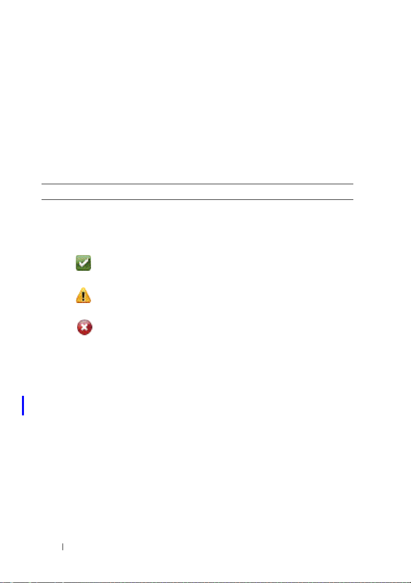
Controller Properties and Tasks
Use this window to view information about the controller and execute
controller tasks.
Controller Properties
The controller properties can vary depending on the model of the controller.
Controller properties may include:
Table 7-3. Controller Properties
Property Definition
Status These icons represent the severity or health of the storage
component.
For more information, see
Normal/OK
Warning/Non-critical
Critical/Fatal
ID This property displays the controller ID assigned to the
controller by Storage Management. Storage Management
numbers the controllers attached to the system starting with
zero. This number is the same as the controller ID number
reported by the
Command Line Interface, see the Server Administrator
Command Line Interface User’s Guide.
Name This property displays the name of the controller.
State This property displays the current status of the controller.
Possible values are:
Ready—The controller is functioning normally.
Degraded—The controller has encountered a failure and is
operating in a degraded state.
Failed—The controller has encountered a failure and is no
longer functioning.
omreport Command. For information on
Storage Component Severity
.
84 Controllers
Page 85

Property Definition
Firmware Version This property displays the version of the firmware that is
currently installed on the controller.
NOTE: On some controllers, Storage Management may not be
able to obtain the firmware version. In this case, Storage
Management displays Not Applicable.
Minimum Required
Firmware Version
Driver Version This property displays the version of the driver that is
This property displays the minimum firmware version that is
required by Storage Management. This property is only
displayed if the controller firmware does not meet the
minimum requirement.
The firmware and drivers listed in the Server Administrator
Readme refer to the minimum supported version for these
controllers. Later versions of the firmware and drivers are also
supported. For the most recent driver and firmware
requirements, contact your service provider.
currently installed on the controller.
NOTE: On some controllers, Storage Management may not be
able to obtain the driver version. In this case, Storage
Management displays Not Applicable.
Minimum Required
Driver Version
Number of
Connectors
This property displays the minimum driver version that is
required by Storage Management. This property is only
displayed if the controller driver does not meet the minimum
requirement.
The firmware and drivers listed in the Server Administrator
Readme refer to the minimum supported version for these
controllers. Later versions of the firmware and drivers are also
supported. For the most recent driver and firmware
requirements, contact your service provider.
This property displays the number of connectors the
controller has. Each connector can be attached to physical
disks or an enclosure. Depending on the controller type, the
connector can be either a SCSI channel or a SAS port.
Controllers 85
Page 86

Property Definition
Rebuild Rate The rebuild rate is the percentage of the system’s resources
dedicated to rebuilding a failed disk when a rebuild is
necessary. For more information, see
Set Rebuild Rate
.
NOTE: Revertible Hot Spare operation has the same rebuild
rate that you set here.
BGI Rate The background initialization (BGI) rate is the percentage of
the system’s resources dedicated to performing the
background initialization of a virtual disk after it is created.
For more information, see
Check Consistency
Rate
Reconstruct Rate The reconstruct rate is the percentage of the system’s
Alarm State This property displays whether the controller’s alarm is
The check consistency rate is the percentage of the system’s
resources dedicated to performing a check consistency on a
redundant virtual disk. For more information, see
Consistency
resources dedicated to reconstructing a disk group after
adding a physical disk or changing the RAID level of a virtual
disk residing on the disk group. For more information, see
Reconstruct Rate
enabled or disabled.
.
.
Set Background Initialization Rate
Check
Set
NOTE: This property is displayed only for SCSI storage
controllers.
Abort check
consistency on error
Allow Revertible Hot
Spare and Replace
Member
Loadbalance This property provides the ability to automatically use both
This property enables you to stop the Check Consistency
operation on error rather than continuing. This property is
available only on controllers that have controller firmware
version 6.1 and later.
This property enables the automatic copying of data from a
physical disk to a hot spare (in case of predictive failure) or
from a hot spare to a physical disk (in case of replacement of a
degraded disk). For more information, see
Spare
.
controller ports or connectors connected to the same
enclosure to route I/O requests. This property is available only
on SAS controllers that have controller firmware version 6.1
and later. For more information, see
Revertible Hot
Redundant path view
.
.
86 Controllers
Page 87

Property Definition
Auto replace member
on predictive failure
Redundant path view Indicates whether Storage Management has detected a
Encryption Capable Indicates whether the controller has the capability to support
Encryption Key
Present
Encryption Mode Indicates whether the controller is using Local Key
Cache Memory Size This property displays the size of the controller’s cache
Patrol Read Mode This property displays the Patrol Read mode setting for the
In case of predictive failure, this property enables the
automatic copying of data from a physical disk to a hot spare.
Use this property in conjunction with the Allow Revertible
Hot Spare and Replace Member property.
redundant path configuration. Storage Management detects a
redundant path configuration when both controller ports are
connected to the same enclosure that is in a unified mode.
For more information, see
encryption. Possible values are Yes and No.
Indicates whether the controller has an Encryption Key
established. Possible values are Yes and No.
Management (LKM) or None. For more information, see
Manage Encryption Key
memory.
controller. Possible values are:
Auto—When set to Auto, a Patrol Read runs continuously on
the system. When one iteration of the Patrol Read is
complete, the next Patrol Read is scheduled to start within a
period of time specified by the controller. You do not have the
option of manually starting or stopping the Patrol Read in
Auto mode.
Manual—When set to Manual, you can start or stop the
Patrol Read process.
Disabled—This property indicates that the Patrol Read
process is disabled.
For more information about Patrol Read, see
Mode
and
Start and Stop Patrol Read
Redundant Path Configuration
.
Set Patrol Read
.
.
Controllers 87
Page 88

Property Definition
Patrol Read State This property displays the current state of the Patrol Read
process. Possible values are:
Ready—The Patrol Read process is enabled and runs when
next scheduled or when manually initiated.
Active—The Patrol Read process is currently running.
Stopped—The Patrol Read has been stopped.
For more information about Patrol Read, see
.
Mode
Patrol Read Rate This property represents the percentage of the system
resources dedicated for running the Patrol Read operation. It
changes the amount of system resources assigned for the
Patrol Read task. The patrol read rate can be configured
between 0% and 100%, where:
• 0% — indicates the lowest priority for controllers and has the
least impact on the system performance.
• 100% — indicates the highest priority for controllers and has
a greater impact on the system performance.
Patrol Read
Iterations
Cluster Mode This property indicates whether the controller is part of a
Persistent Hot Spare The possible values are:
This property displays the number of Patrol Read iterations.
For more information about Patrol Read, see
.
Mode
cluster configuration.
Enabled: The slot corresponding to the hot spare drive is
persistent. Any drive in the slot functions as a hot spare if the
drive is qualified to be a hot spare.
Set Patrol Read
Set Patrol Read
NOTE: Any drive in the slot functions as a hot spare. If the drive
contains foreign data, it is overwritten.
Disabled: The slot corresponding to the hot spare drive is not
persistent. If the drive is removed from the slot and any drive
is inserted, the slot stops function as a hot spare. You need to
manually assign the drive as a hot spare again.
Controller Tasks Enables you to configure and manage the controller. For more
information, see
Controller Tasks
.
88 Controllers
Page 89

Property Definition
Available Reports Enables you to view Patrol Read report, Check Consistency
report, Slot Occupancy report, and Physical Disk Firmware
Version Report. For more information, see
Available Reports
Controller Tasks
To execute a controller task:
1
Expand the
2
Select a controller object.
3
Select the
4
Select a task from the
5
Click
NOTE: Different controllers support different features. For this reason, the tasks
displayed on the Tasks drop-down menu can vary depending on which controller is
selected in the tree view. If no tasks can be performed because of controller or
system configuration limitations, then the Tasks drop-down menu displays No Task
Available.
Controller Tasks
• Rescan Controller
•Create Virtual Disk
• Enable Alarm (Controller)
• Disable Alarm (Controller)
• Quiet Alarm (Controller)
• Test Alarm (Controller)
•Set Rebuild Rate
• Reset Configuration
•Export Log
• Foreign Configuration Operations
• Importing Foreign Configurations
• Importing/Recovering Foreign Configurations
• Clear Foreign Configuration
Storage
tree object to display the controller objects.
Information/Configuration
Available Tasks
Execute
.
subtab.
drop-down menu.
.
Controllers 89
Page 90

• Set Background Initialization Rate
• Set Check Consistency Rate
• Set Reconstruct Rate
•Set Patrol Read Mode
• Start and Stop Patrol Read
• Manage Preserved Cache
• Change Controller Properties
• Manage Physical Disk Power
•Manage Encryption Key
• Convert to RAID Capable Disks
• Convert to Non-RAID Disks
Available Reports
To view a report:
1
Expand the
2
Select a controller object.
3
Select the
4
Select a report from the
5
Click
Storage
Information/Configuration
Execute
tree object to display the controller objects.
Select Report
.
subtab.
drop-down menu.
Available Reports
• Patrol Read Report
• Check Consistency Report
• Slot Occupancy Report
• Physical Disk Firmware Version Report
Rescan Controller
Does my controller support this feature? See
90 Controllers
Supported Features
.
Page 91

On SCSI controllers, a rescan updates configuration changes (such as new or
removed devices) for all components attached to the controller. For
information on when you may want to do a rescan, see
Storage Configuration Changes
NOTE: Rescan Controller is not supported on non-RAID SCSI controllers. You must
reboot the system before Storage Management can see configuration changes on
non-RAID SCSI controllers. Otherwise, configuration changes are not reflected in
the Storage Management graphical user interface (GUI).
To rescan a controller:
1
Expand the tree view to display the controller object.
2
Select the
3
Click the
4
Select
5
Click
Controller
Configuration/Information
Rescan
from the
Execute
.
.
object.
Controller Tasks
subtab.
drop-down menu.
Rescan to Update
You can also locate this task from the Change Controller Properties drop
down menu. For more information, see
Create Virtual Disk
Does my controller support this feature? See
Change Controller Properties
Supported Features
.
.
Use the Create Virtual Disk task to launch the Create Virtual Disk Express
Wizard. For more information, see
Create Virtual Disk Express Wizard
.
Enable Alarm (Controller)
Does my controller support this feature? See
Supported Features
.
Use the Enable Alarm task to enable the controller’s alarm. When enabled,
the alarm sounds in the event of a device failure.
Disable Alarm (Controller)
Does my controller support this feature? See
Supported Features
.
Use the Disable Alarm task to disable the controller’s alarm. When disabled,
the alarm does not sound in the event of a device failure.
Controllers 91
Page 92

Quiet Alarm (Controller)
Does my controller support this feature? See
Supported Features
.
Use the Quiet Alarm task to quiet the controller’s alarm when it is sounding.
After it is quieted, the alarm is still enabled in the event of a future device
failure.
Test Alarm (Controller)
Does my controller support this feature? See
Supported Features
.
Use the Test Alarm task to test whether the controller alarm is functional.
The alarm sounds for about 2 seconds.
Set Rebuild Rate
Does my controller support this feature? See
Supported Features
.
Use the Set Rebuild Rate task to change the rebuild rate. For more
information, see
Export Log File
Does my controller support this feature? See
Set Rebuild Rate
.
Supported Features
.
Use this task to export the controller log to a text file. For more information,
see
Export Log
Controller Components
.
For information on attached components, see the following topics:
• Battery Properties and Tasks
• Connector Properties and Tasks
• Enclosure and Backplane Properties and Tasks
• Firmware/Driver Properties
• Virtual Disk Properties and Tasks
Foreign Configuration Operations
Does my controller support this feature? See
92 Controllers
Supported Features
.
Page 93

The Foreign Configuration Operations task provides a preview of the foreign
configurations that you can import. This task is available on PERC 6
controllers with firmware version 6.1 and later. For more information, see
Foreign Configuration Operations
Manage Physical Disk Power
Does my controller support this feature? See
.
Supported Features
.
The Manage Physical Disk Power task allows to manage the power consumed
by the physical disks by spinning down the hotspares and unconfigured drives
if there is no I/O activity for a specified amount of time. This option is
supported with PERC H700, H800, and H310 cards. Additionally, PERC
H810, H710, and H710P cards support power saving configurations on
unconfigured, Hot Spare, and configured disks.
Controllers 93
Page 94

Set Rebuild Rate
Does my controller support this feature? See
The Set Rebuild Rate task changes the controller’s rebuild rate.
During a rebuild, the complete contents of a physical disk are reconstructed.
The rebuild rate, configurable between 0% and 100%, represents the
percentage of the system resources dedicated to rebuilding failed physical
disks. At 0%, the rebuild has the lowest priority for the controller, takes the
most time to complete, and is the setting with the least impact to system
performance. A rebuild rate of 0% does not mean that the rebuild is stopped
or paused.
At 100%, the rebuild is the highest priority for the controller, minimizes the
rebuild time, and is the setting with the most impact to system performance.
On the PERC controllers, the controller firmware also uses the rebuild rate
setting to control the system resource allocation for the following tasks. For
these controllers, the rebuild rate setting applies to these tasks in the same
manner that it applies to the Rebuild task.
• Check Consistency
• Background Initialization (see Cancel Background Initialization)
• Full Initialization (A BIOS setting determines whether a full or fast
initialization occurs. See Slow and Fast Initialize.)
• Reconfigure (see Virtual Disk Task: Reconfigure (Step 1 of 3))
To change the controller’s rebuild rate:
1
Type a numerical value in the
be within the 0 – 100 range.
2
Click
Apply Changes
Previous Page
.
. To exit and cancel your changes, click
New Rebuild Rate
Supported Features
text box. The value must
.
Go Back to
To locate this task in Storage Management:
1
Expand the
2
Select a controller object.
3
Select the
4
Select
94 Controllers
Storage
Information/Configuration
Set Rebuild Rate
tree object to display the controller objects.
from the
subtab.
Available Tasks
drop-down menu.
Page 95

5
Click
Execute
.
You can also locate this task from the Change Controller Properties drop
down menu. For more information, see
Change Controller Properties
.
Reset Configuration
Does my controller support this feature? See
Supported Features
.
Use the Reset Configuration task to erase all information on the controller so
that you can perform a fresh configuration. This operation destroys all data
and virtual disks on the controller and unassigns any hot spares.
You must completely reconfigure your storage after performing this operation.
CAUTION: Resetting a configuration permanently destroys all data on all virtual
disks attached to the controller. If the system or boot partition resides on these
virtual disks, it is destroyed.
NOTE: Resetting the controller configuration does not remove a foreign
configuration. To remove a foreign configuration, use the Clear Foreign
Configuration task.
To reset the controller configuration:
1
Review the virtual disks that is destroyed by resetting the controller
configuration. Make backups as necessary. Click
Blink
at the bottom of
the screen to blink the physical disks included in the virtual disks.
2
Click
Reset Configuration
when you are ready to erase all information on
the controller. To exit without resetting the controller configuration, click
Go Back to Previous Page
.
Controllers 95
Page 96

To locate this task in Storage Management:
1
Expand the
2
Select a controller object.
3
Select the
4
Select
5
Click
You can also locate this task from the Change Controller Properties drop
down menu. For more information, see
Storage
Information/Configuration
Reset Configuration
Execute
tree object to display the controller objects.
.
subtab.
from the
Available Tasks
Change Controller Properties
drop-down menu.
.
Export Log
Does my controller support this feature? See
The Export Log task exports the controller log to a text file. The log gives
detailed information on the controller activities and can be useful for
troubleshooting.
On a system running
windows or winnt directory. On a system running Linux operating systems,
the log file is exported to the /var/log directory.
Depending on the controller, the log file name is either afa_<
lsi_<
mmdd
>.log where <
NOTE: In the VMware ESXi environment, only one log file is created (lsiexport.log).
If the file already exists, exporting the log file overwrites the existing log file.
NOTE: Controllers without cache cannot store logs and export log files.
To export the controller log file:
Click Export Log File when ready. To exit without exporting the controller
log file, click Go Back to Previous Page.
To locate this task in Storage Management:
1
Expand the
2
Select a controller object.
3
Select the
4
Select
Export Log
Microsoft Windows, the log file is exported to the
mmdd
> is the month and date.
Storage
Information/Configuration
tree object to display the controller objects.
from the
Available Tasks
Supported Features
subtab.
drop-down menu.
.
mmdd
>.log or
96 Controllers
Page 97

5
Click
Execute
.
You can also locate this task from the Change Controller Properties drop
down menu. For more information, see
Change Controller Properties
.
Foreign Configuration Operations
NOTE: Foreign Configuration Operations is available only on SAS controllers with
firmware versions 6.1 and later.
A foreign configuration is data residing on physical disks that has been moved
from one controller to another. Virtual disks residing on physical disks that
have been moved are considered to be a foreign configuration.
NOTE: It is not recommend to remove an external enclosure cable while the
operating system is running on the system. Removing the cable could result in a
foreign configuration when the connection is re-established.
The Foreign Configuration Operations option is displayed only when a
controller detects a foreign configuration. Select this option and click
Execute to display the Foreign Configuration Preview page.
The Foreign Configuration Preview screen provides a preview of the foreign
disks and enables you to perform operations such as, importing, recovering, or
clearing the foreign disks. You can also import or clear a locked foreign
configuration.
• If any foreign configurations locked using
detected, the associated
Encryption Key Identifier
you to enter the corresponding Passphrase to unlock the drives.
To avoid unlocking foreign configurations and to proceed to
preview/import/clear a foreign configuration that has not been locked, click
Skip or Continue.
If you do not want to import/clear the foreign configurations, or in case of loss
of the associated Passphrase of the corresponding Encryption Key Identifier,
execute the Instant Encrypt Erase task for the physical disks.
Local Key manager (LKM)
is displayed prompting
are
CAUTION: Executing the Instant Encrypt Erase task erases all data on the
physical disk.
Some conditions, such as an unsupported RAID level or an incomplete disk
group, can prevent the import or recovery of foreign virtual disks.
Controllers 97
Page 98

Foreign Configuration Properties
The following table describes the properties that are displayed for the Foreign
Disks and Global Hot Spares.
Table 7-4. Foreign Configuration Properties
Property Definition
Status These icons represent the severity or health of the storage
component.
Normal/OK
Warning/Non-critical
Critical/Fatal
For more information, see
Name This property displays the name of the foreign configuration and is
available as a link. The link enables you to access the physical disks
that constitute the foreign disk.
Storage Component Severity
.
98 Controllers
Page 99

Property Definition
State This property displays the current state of the foreign configuration.
Ready—The foreign disk can be imported and functions normally
after import.
Degraded—The foreign disk is in degraded state and rebuilds after
import.
Failed—The foreign disk has encountered a failure and is no longer
functioning. You cannot import the foreign configuration.
The foreign configuration may be in degraded or failed state due to
any of the following reasons:
• Missing physical disk—One of the physical disks in the potential
virtual disk is missing or not available.
• Missing Span—One or more span of a hybrid virtual disk is missing
• Stale physical disks—One or more physical disk in the
configuration may contain out-of-date data with respect to other
disks of that virtual disk. Hence, the data integrity of the imported
virtual disk is not intact.
• Unsupported configuration of the virtual disk—The virtual disk has
an unsupported RAID level.
• The virtual disks available for import exceed the number of virtual
disk available for export.
• Incompatible physical disks—Configuration on the physical disks is
not recognized by the RAID firmware.
• Orphan drive—A physical disk in the foreign configuration has
configuration information that matches another physical disk that
is already a part of an array (either a foreign or a native array).
NOTE: For other applicable physical disk tasks and properties, see
Physical Disk or Physical Device Properties and Tasks
Layout This property displays the RAID level of the foreign configuration.
.
Controllers 99
Page 100

Property Definition
Remarks This property gives more information about the foreign virtual disk.
If the virtual disk cannot be imported, the reason for failure is
displayed.
• Exceeded Maximum—The number of virtual disks selected for
import has exceeded the maximum number of supported disks.
• Missing physical disk or missing span—One or more physical disks
or spans in the virtual disk to be imported is missing.
• Unsupported—The selected RAID level is not supported on this
controller.
• Orphan Drive—The physical disk was once part of a RAID volume
but was replaced. The configuration should be cleared.
• Stale Physical Disk—The physical disk in the virtual disk to be
imported has outdated data.
• Partially Foreign—The virtual disk is part of an already existing
configuration. Some physical disks in this virtual disk are foreign.
Dedicated Hot
Spare
This property displays whether the foreign disk is a dedicated hot
spare.
Based on this information, you can decide whether you want to import,
recover, or clear the foreign configuration.
To preview the import of foreign configuration
Click Foreign Configuration Operations from the Controller Tasks drop
down menu. Click Execute to display the Foreign Configuration Preview
screen.
To locate this task in Storage Management
For SAS controllers with firmware version 6.1:
1
Expand the
2
Select a controller object.
3
Select the
4
Select
Ta s ks
5
Click
Storage
tree object to display the controller objects.
Information/Configuration
Foreign Configuration Operations
drop-down menu.
Execute
.
100 Controllers
subtab.
from the
Controller Available
 Loading...