

Page 1
Dell™OpenManage™ServerAdministratorStorageManagementUser's
Guide
Notes and Cautions
Information in this document is subject to change without notice.
©2009 Dell Inc. All rights reserved.
Reproduction in any manner whatsoever without the written permission of Dell Inc. is strictly forbidden.
Trademarks used in this text: Dell, the DELL logo, PowerVault, and Dell OpenManage are trademarks of Dell Inc.; Microsoft, Windows are registered trademarks and Windows Server is
a trademark of Microsoft Corporation in the United States and other countries; VMware is a registered trademark of VMware Inc.
Server Administrator includes software developed by the Apache Software Foundation (www.apache.org). Server Administrator utilizes the OverLIB JavaScript library. This library can
be obtained from www.bosrup.com.
Other trademarks and trade names may be used in this document to refer to either the entities claiming the marks and names or their products. Dell Inc. disclaims any
proprietary interest in trademarks and trade names other than its own.
July 2009
Overview
Virtual Disks
Getting Started
Protecting Your Virtual Disk with a Hot Spare
Understanding RAID Concepts
Alert Messages
Quick Access to Storage Status and Tasks
Command Line Interface
Storage Information and Global Tasks
Moving Physical and Virtual Disks from One System to Another
Setting Hot Spare Protection Policy
BIOS Terminology
Controllers
Troubleshooting
RAID Controller Batteries
Frequently Asked Questions
Connectors
Supported Features
Enclosures and Backplanes
Determining the Health Status for Storage Components
Physical Disks
NOTE: A NOTE indicates important information that helps you make better use of your computer.
CAUTION: A CAUTION indicates potential damage to hardware or loss of data if instructions are not followed.
Page 2
Back to Contents Page
Supported Features
Dell™OpenManage™ServerAdministratorStorageManagementUser'sGuide
Different controllers support different features. The tasks displayed by the Storage Management menus and other features vary depending on whether the
controller supports the feature. This appendix identifies the features that each controller supports. For more information, see your hardware documentation.
Supported Features on the PERC 3/SC, 3/DC, 3/QC, 4/SC, 4/DC, 4/Di, 4e/Si, 4e/Di,
4e/DC, CERC ATA100/4ch, and 4/IM Controllers
This section identifies the controller-supported features and whether or not an enclosure can be attached to the controller.
l "Controller Tasks"
l "Battery Tasks"
l "Connector Tasks"
l "Physical Disk Tasks"
l "Virtual Disk Tasks"
l "Virtual Disk Specifications"
l "Supported RAID Levels"
l "Read, Write, and Disk Cache Policy"
l "Enclosure Support"
For enclosure-supported tasks, see "Enclosure and Backplane Features."
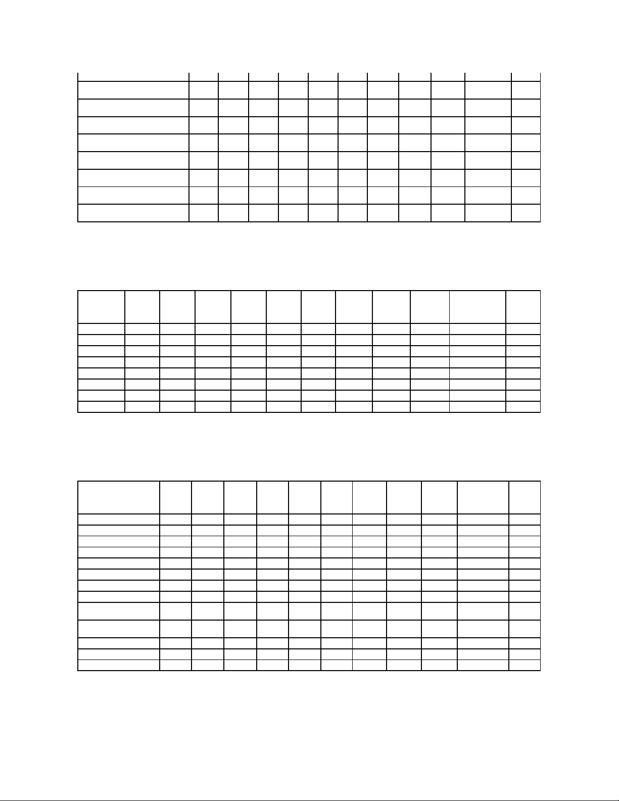
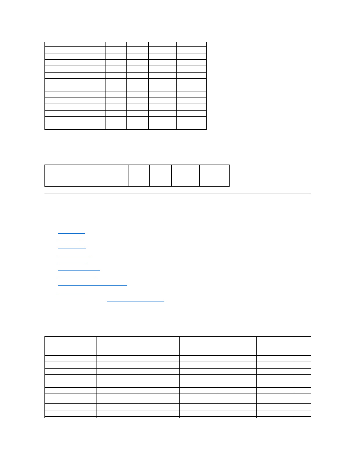
Controller Tasks
Table A-1. Controller Tasks Supported by the PERC 3/SC, 3/DC, 3/QC, 4/SC, 4/DC, 4/Di, 4e/Si, 4e/Di, 4e/DC, CERC ATA100/4ch, and
4/IMControllers
Supported Features on the PERC 3/SC, 3/DC, 3/QC, 4/SC, 4/DC, 4/Di, 4e/Si, 4e/Di,
4e/DC, CERC ATA100/4ch, and 4/IM Controllers
Supported Features on the PERC S100 and S300 Controllers
Supported Features on the PERC 3/Si, 3/Di, CERC SATA1.5/2s, and CERC SATA1.5/6ch
Controllers
Supported Features on the Non-RAID Controllers
Supported Features on the PERC 5/E, PERC 5/i, PERC 6/E, PERC 6/I, PERC 6/I Modular,
and CERC 6/I Controllers
Enclosure and Backplane Features
Supported Features on the SAS 5/iR and SAS 6/iR Controllers
Maximum Supported Configuration
Controller Task Name
PERC
3/SC
PERC
3/DC
PERC
3/QC
PERC
4/SC
PERC
4/DC
PERC
4/DI
PERC
4e/SI
PERC
4e/DI
PERC
4e/DC
CERC ATA
100/4ch
PERC
4/IM
Enable Alarm
Yes
Yes
Yes
Yes
Yes
No
No
No
Yes
Yes
No
Disable Alarm
Yes
Yes
Yes
Yes
Yes
No
No
No
Yes
Yes
No
Quiet Alarm
Yes
Yes
Yes
Yes
Yes
No
No
No
Yes
Yes
No
Test Alarm
No
No
No
No
No
No
No
No
No
No
No
Reset configuration
Yes
Yes
Yes
Yes
Yes
Yes
Yes
Yes
Yes
Yes
No
Set Rebuild Rate
Yes
Yes
Yes
Yes
Yes
Yes
Yes
Yes
Yes
Yes
No
Set Background Initialization Rate
No
No
No
No
No
No
No
No
No
No
No
Set Check Consistency Rate
No
No
No
No
No
No
No
No
No
No
No
Set Reconstruct Rate
No
No
No
No
No
No
No
No
No
No
No
Rescan Controller
Yes
Yes
Yes
Yes
Yes
Yes
Yes
Yes
Yes
Yes
Yes
Create Virtual Disk
Yes
Yes
Yes
Yes
Yes
Yes
Yes
Yes
Yes
Yes
No
Export Log File
Yes
Yes
Yes
Yes
Yes
Yes
Yes
Yes
Yes
Yes
No
Clear Foreign Configuration
No
No
No
No
No
No
No
No
No
No
No
Import Foreign Configuration
No
No
No
No
No
No
No
No
No
No
No
Import/Recover Foreign
Configuration
No
No
No
No
No
No
No
No
No
No
No
Set Patrol Read Mode
NOTE: ForPERC4controllers,
(Manual mode is not available).
No
No
No
Yes
Yes
Yes
Yes
Yes
Yes
No
No
Page 3
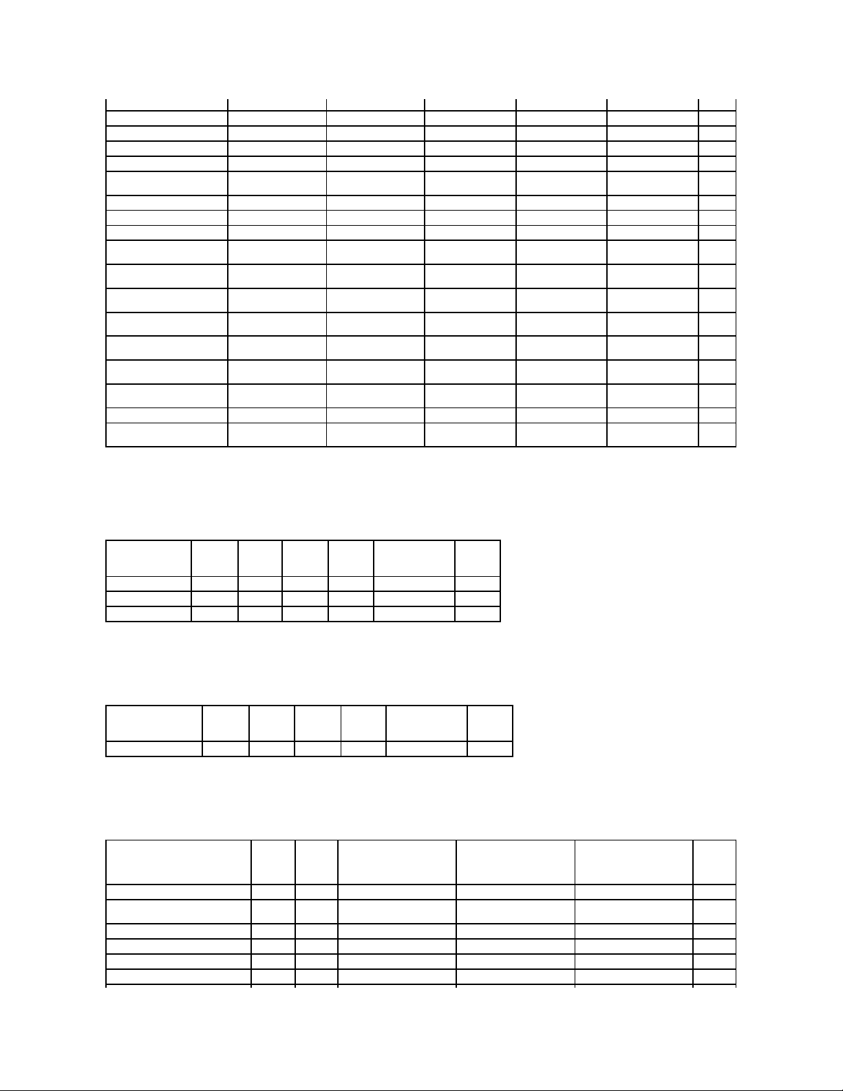
Battery Tasks
Table A-2. Battery Tasks Supported by the PERC 3/SC, 3/DC, 3/QC, 4/SC, 4/DC, 4/Di, 4e/Si, 4e/Di, 4e/DC, CERC ATA100/4ch, and 4/IM
Controllers
Connector Tasks
Table A-3. Connector Tasks Supported by the PERC 3/SC, 3/DC, 3/QC, 4/SC, 4/DC, 4/Di, 4e/Si, 4e/Di, 4e/DC, CERC ATA100/4ch, and
4/IMControllers
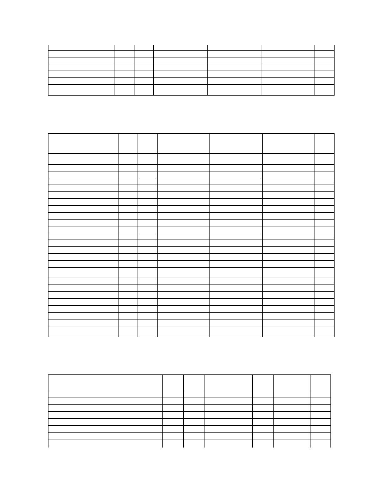
Physical Disk Tasks
Table A-4. Physical Disk Tasks Supported by the PERC 3/SC, 3/DC, 3/QC, 4/SC, 4/DC, 4/Di, 4e/Si, 4e/Di, 4e/DC, CERC ATA100/4ch, and
4/IMControllers
Virtual Disk Tasks
Table A-5. Virtual Disk Tasks Supported by the PERC 3/SC, 3/DC, 3/QC, 4/SC, 4/DC, 4/Di, 4e/Si, 4e/Di, 4e/DC, CERC ATA100/4ch, and
4/IMControllers
Start Patrol Read
No
No
No
No
No
No
No
No
No
No
No
Stop Patrol Read
No
No
No
No
No
No
No
No
No
No
No
Battery Task
Name
PERC
3/SC
PERC
3/DC
PERC
3/QC
PERC
4/SC
PERC
4/DC
PERC
4/DI
PERC
4e/SI
PERC
4e/DI
PERC
4e/DC
CERC ATA
100/4ch
PERC
4/IM
Recondition
Battery
No
No
No
No
No
No
No
No
No
No
No
Start Learn Cycle
No
No
No
No
No
No
No
No
No
No
No
Delay Learn
Cycle
No
No
No
No
No
No
No
No
No
No
No Connector Task
Name
PERC
3/SC
PERC
3/DC
PERC
3/QC
PERC
4/SC
PERC
4/DC
PERC
4/DI
PERC
4e/SI
PERC
4e/DI
PERC
4e/DC
CERC ATA
100/4ch
PERC
4/IM
Connector Rescan
Yes
Yes
Yes
Yes
Yes
Yes
Yes
Yes
Yes
Yes
Yes
Physical Disk Task
Name
PERC
3/SC
PERC
3/DC
PERC
3/QC
PERC
4/SC
PERC
4/DC
PERC
4/DI
PERC
4e/SI
PERC
4e/DI
PERC
4e/DC
CERC ATA
100/4ch
PERC 4/IM
Blink/Unblink
Yes
Yes
Yes
Yes
Yes
Yes
Yes
Yes
Yes
No
Yes
Task only available when an
enclosure or backplane and LEDs
on the physical disks are present.
Assign and
Unassign Global Hot
Spare
Yes
Yes
Yes
Yes
Yes
Yes
Yes
Yes
Yes
Yes
No
Prepare to Remove
Yes
Yes
Yes
Yes
Yes
Yes
Yes
Yes
Yes
No
No
Offline
Yes
Yes
Yes
Yes
Yes
Yes
Yes
Yes
Yes
Yes
No
Online
Yes
Yes
Yes
Yes
Yes
Yes
Yes
Yes
Yes
Yes
No
Initialize
No
No
No
No
No
No
No
No
No
No
No
Rebuild
Yes
Yes
Yes
Yes
Yes
Yes
Yes
Yes
Yes
No
No
Cancel Rebuild
Yes
Yes
Yes
Yes
Yes
Yes
Yes
Yes
Yes
No
No
Remove Dead Disk
Segments
No
No
No
No
No
No
No
No
No
No
No
Format Disk
No
No
No
No
No
No
No
No
No
No
No
Clear
No
No
No
No
No
No
No
No
No
No
No
Cancel Clear
No
No
No
No
No
No
No
No
No
No
No
Page 4
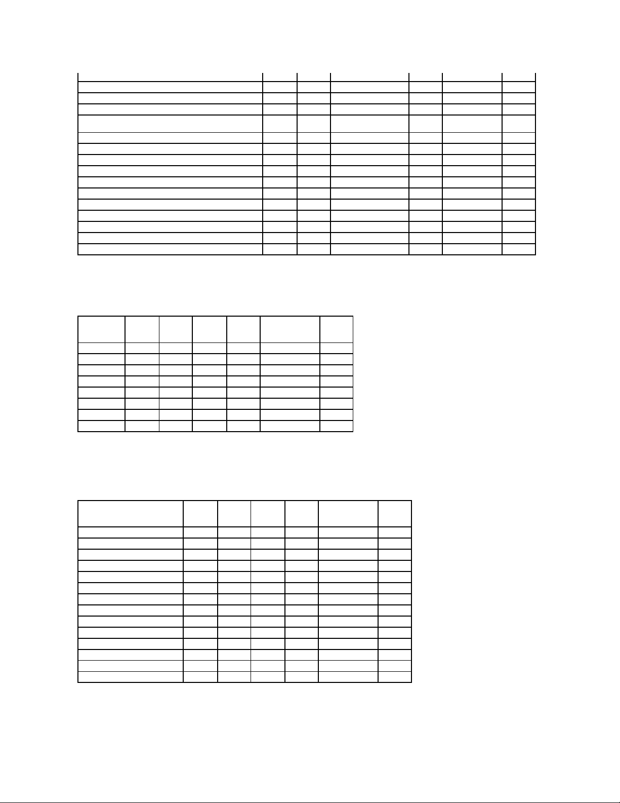
Virtual Disk Specifications
Table A-6. Virtual Disk Specifications for the PERC 3/SC, 3/DC, 3/QC, 4/SC, 4/DC, 4/Di, 4e/Si, 4e/Di, 4e/DC, CERC ATA100/4ch, and 4/IM
Controllers
Virtual Disk Task Name
PERC
3/SC
PERC
3/DC
PERC
3/QC
PERC
4/SC
PERC
4/DC
PERC
4/DI
PERC
4e/SI
PERC
4e/DI
PERC
4e/DC
CERC ATA
100/4ch
PERC
4/IM
Assign and Unassign
Dedicated Hot Spare
Yes
Yes
Yes
Yes
Yes
Yes
Yes
Yes
Yes
Yes
No
Create Virtual Disk
Yes
Yes
Yes
Yes
Yes
Yes
Yes
Yes
Yes
Yes
No
Create Virtual Disk Advanced
Wizard
Yes
Yes
Yes
Yes
Yes
Yes
Yes
Yes
Yes
Yes
No
Create Virtual Disk Express
Wizard
Yes
Yes
Yes
Yes
Yes
Yes
Yes
Yes
Yes
Yes
No
Rename
Yes
Yes
Yes
Yes
Yes
Yes
Yes
Yes
Yes
Yes
Yes
Blink/Unblink
Yes
Yes
Yes
Yes
Yes
Yes
Yes
Yes
Yes
No
Yes
Reconfigure
Yes
Yes
Yes
Yes
Yes
Yes
Yes
Yes
Yes
Yes
No
Change Policy
Yes
Yes
Yes
Yes
Yes
Yes
Yes
Yes
Yes
Yes
No
Split Mirror
No
No
No
No
No
No
No
No
No
No
No
Unmirror
No
No
No
No
No
No
No
No
No
No
No
Delete Last Virtual Disk
Yes
Yes
Yes
Yes
Yes
Yes
Yes
Yes
Yes
Yes
No
Delete (any) Virtual Disk
Yes
Yes
Yes
Yes
Yes
Yes
Yes
Yes
Yes
Yes
No
Check Consistency
Yes
Yes
Yes
Yes
Yes
Yes
Yes
Yes
Yes
Yes
No
Cancel Check Consistency
Yes
Yes
Yes
Yes
Yes
Yes
Yes
Yes
Yes
Yes
No
Pause Check Consistency
No
No
No
No
No
No
No
No
No
No
No
Resume Check Consistency
No
No
No
No
No
No
No
No
No
No
No
Cancel Background
Initialization (BGI)
Yes
Yes
Yes
Yes
Yes
Yes
Yes
Yes
Yes
No
No
Format Virtual Disk
No
No
No
No
No
No
No
No
No
No
No
Cancel Format Virtual Disk
No
No
No
No
No
No
No
No
No
No
No
Restore Dead Disk Segments
No
No
No
No
No
No
No
No
No
No
No
Initialize Virtual Disk
Yes
Yes
Yes
Yes
Yes
Yes
Yes
Yes
Yes
Yes
No
Fast Initialize Virtual Disk
No
No
No
No
No
No
No
No
No
No
No
Slow Initialize Virtual Disk
No
No
No
No
No
No
No
No
No
No
No
Cancel Initialize Virtual Disk
Yes
Yes
Yes
Yes
Yes
Yes
Yes
Yes
Yes
Yes
No
Virtual Disk Specification
PERC
3/SC
PERC
3/DC
PERC
3/QC
PERC
4/SC
PERC
4/DC
PERC
4/DI
PERC
4e/SI
PERC
4e/DI
PERC
4e/DC
CERC ATA
100/4ch
PERC
4/IM
Maximum Number of Virtual Disks
per Controller
40
40
40
40
40
40
40
40
40
40 1 Minimum Virtual Disk Size
100
MB
100
MB
100
MB
100
MB
100
MB
100
MB
100
MB
100
MB
100
MB
100
MB
Max
Maximum Virtual Disk Size
2TB
2TB
2TB
2TB
2TB
2TB
2TB
2TB
2TB
2TB
2TB
Maximum Number of Spans per
Virtual Disk
8 8 8 8 8 8 8 8 8 8 1
Maximum Number of Physical Disks
per Span
32
32
32
32
32
32
32
32
32
32
2
Minimum Stripe Size
2k
2k
2k
2k
2k
2k
2k
2k
2k
2k
NA
Maximum Stripe Size
128k
128k
128k
128k
128k
128k
128k
128k
128k
128k
NA
Maximum Number of Virtual Disks
per Disk Group
16
16
16
16
16
16
16
16
16
16 1 Maximum Number of Physical Disks
that Can Be Concatenated
8 8 8 8 8 8 8 8 8 8 NA
Maximum Number of Physical Disks
in a RAID 0
32
32
32
32
32
32
32
32
32
32
NA
Maximum Physical Disks in a RAID 1
2 2 2 2 2 2 2 2 2 2 2
Maximum Number of Physical Disks
in a RAID 5
32
32
32
32
32
32
32
32
32
32
NA
Maximum Number of Physical Disks
in a RAID 10
16
16
16
16
16
16
16
16
16
16
NA
Maximum Number of Physical Disks
in a RAID 50
256
256
256
256
256
256
256
256
256
NA
NA
Minimum Number of Physical Disks
that Can Be Concatenated
2 2 2 2 2 2 2 2 2 2 NA
Minimum Number of Physical Disks in
1 1 1 1 1 1 1 1 1 1 NA
Page 5
Supported RAID Levels
Table A-7. RAID Levels Supported by the PERC 3/SC, 3/DC, 3/QC, 4/SC, 4/DC, 4/Di, 4e/Si, 4e/Di, 4e/DC, CERC ATA100/4ch, and 4/IM
Controllers
Read, Write, and Disk Cache Policy
Table A-8. Read, Write and Disk Cache Policy Supported by the PERC 3/SC, 3/DC, 3/QC, 4/SC, 4/DC, 4/Di, 4e/Si, 4e/Di, 4e/DC, CERC
ATA100/4ch,and4/IMControllers
Enclosure Support
Table A-9. Enclosure Support on the PERC 3/SC, 3/DC, 3/QC, 4/SC, 4/DC, 4/Di, 4e/Si, 4e/Di, 4e/DC, CERC ATA100/4ch, and 4/IM
a RAID 0
Minimum Number of Physical Disks in
a RAID 1
2 2 2 2 2 2 2 2 2 2 2
Minimum Number of Physical Disks in
a RAID 5
3 3 3 3 3 3 3 3 3 3 NA
Minimum Number of Physical Disks in
a RAID 10
4 4 4 4 4 4 4 4 4 4 NA
Minimum Number of Physical Disks in
a RAID 50
6 6 6 6 6 6 6 6 6
NA
NA
Maximum number of physical disks in
a RAID 6
NA
NA
NA
NA
NA
NA
NA
NA
NA
NA
NA
Maximum number of physical disks in
a RAID 60
NA
NA
NA
NA
NA
NA
NA
NA
NA
NA
NA
Minimum number of physical disks in
a RAID 6
NA
NA
NA
NA
NA
NA
NA
NA
NA
NA
NA
Minimum number of physical disks in
a RAID 60
NA
NA
NA
NA
NA
NA
NA
NA
NA
NA
NA RAID Level
PERC
3/SC
PERC
3/DC
PERC
3/QC
PERC
4/SC
PERC
4/DC
PERC
4/DI
PERC
4e/SI
PERC
4e/DI
PERC
4e/DC
CERC ATA
100/4ch
PERC
4/IM
Concatenation
Yes
Yes
Yes
Yes
Yes
Yes
Yes
Yes
Yes
Yes
No
RAID 0
Yes
Yes
Yes
Yes
Yes
Yes
Yes
Yes
Yes
Yes
No
RAID 1
Yes
Yes
Yes
Yes
Yes
Yes
Yes
Yes
Yes
Yes
Yes
RAID 5
Yes
Yes
Yes
Yes
Yes
Yes
Yes
Yes
Yes
Yes
No
RAID 10
Yes
Yes
Yes
Yes
Yes
Yes
Yes
Yes
Yes
Yes
No
RAID 50
Yes
Yes
Yes
Yes
Yes
Yes
Yes
Yes
Yes
No
No
RAID 6
No
No
No
No
No
No
No
No
No
No
No
RAID 60
No
No
No
No
No
No
No
No
No
No
No
Read, Write, and Disk
Cache Policy
PERC
3/SC
PERC
3/DC
PERC
3/QC
PERC
4/SC
PERC
4/DC
PERC
4/DI
PERC
4e/SI
PERC
4e/DI
PERC
4e/DC
CERC ATA
100/4ch
PERC
4/IM
Cache settings
Yes
Yes
Yes
Yes
Yes
Yes
Yes
Yes
Yes
Yes
No
Read Policy
Yes
Yes
Yes
Yes
Yes
Yes
Yes
Yes
Yes
Yes
No
Read Ahead (Enabled)
Yes
Yes
Yes
Yes
Yes
Yes
Yes
Yes
Yes
Yes
No
Adaptive Read Ahead
Yes
Yes
Yes
Yes
Yes
Yes
Yes
Yes
Yes
Yes
No
No Read Ahead (Disabled)
Yes
Yes
Yes
Yes
Yes
Yes
Yes
Yes
Yes
Yes
No
Write Policy
Yes
Yes
Yes
Yes
Yes
Yes
Yes
Yes
Yes
Yes
No
Write Back (Enabled)
Yes
Yes
Yes
Yes
Yes
Yes
Yes
Yes
Yes
Yes
No
Write Through (Disabled)
Yes
Yes
Yes
Yes
Yes
Yes
Yes
Yes
Yes
Yes
No
Force Write Back (Enabled
Always)
No
No
No
No
No
No
No
No
No
No
No
Write Cache Enabled
Protected
No
No
No
No
No
No
No
No
No
No
No
Disk Cache Policy
Yes
Yes
Yes
Yes
Yes
Yes
Yes
Yes
Yes
Yes
No
Cache I/O
Yes
Yes
Yes
Yes
Yes
Yes
Yes
Yes
Yes
Yes
No
Direct I/O
Yes
Yes
Yes
Yes
Yes
Yes
Yes
Yes
Yes
Yes
No
Page 6
Controllers
Supported Features on the PERC 3/Si, 3/Di, CERC SATA1.5/2s, and CERC
SATA1.5/6ch Controllers
This section identifies the controller-supported features and whether or not an enclosure can be attached to the controller.
l "Controller Tasks"
l "Battery Tasks"
l "Connector Tasks"
l "Physical Disk Tasks"
l "Virtual Disk Tasks"
l "Virtual Disk Specifications"
l "Supported RAID Levels"
l "Read, Write, and Disk Cache Policy"
l "Enclosure Support"
For enclosure-supported tasks, see "Enclosure and Backplane Features."
Controller Tasks
Table A-10.ControllerTasksSupportedbythePERC3/Si,3/Di,CERCSATA1.5/2s,andCERCSATA1.5/6chControllers
Battery Tasks
Table A-11.BatteryTasksSupportedbythePERC3/Si,3/Di,CERCSATA1.5/2s,andCERCSATA1.5/6chControllers
Enclosure Support
PERC
3/SC
PERC
3/DC
PERC
3/QC
PERC
4/SC
PERC
4/DC
PERC
4/DI
PERC
4e/SI
PERC
4e/DI
PERC
4e/DC
CERC ATA
100/4ch
PERC
4/IM
Can an enclosure be attached
to this controller?
Yes
Yes
Yes
Yes
Yes
Yes
Yes
Yes
Yes
No
No
Controller Task Name
PERC 3/Si
PERC 3/Di
CERC SATA 1.5/2s
CERC SATA 1.5/6ch
Enable Alarm
No
No
No
Yes
Disable Alarm
No
No
No
Yes
Quiet Alarm
No
No
No
Yes
Test Alarm
No
No
No
Yes
Reset configuration
Yes
Yes
Yes
Yes
Set Rebuild Rate
No
No
No
No
Set Background Initialization Rate
No
No
No
No
Set Check Consistency Rate
No
No
No
No
Set Reconstruct Rate
No
No
No
No
Rescan Controller
Yes
Yes
Yes
Yes
Create Virtual Disk
Yes
Yes
Yes
Yes
Export Log File
Yes
Yes
No
Yes
Clear Foreign Configuration
No
No
No
No
Import Foreign Configuration
No
No
No
No
Import/Recover Foreign Configuration
No
No
No
No
Set Patrol Read Mode
No
No
No
No
Start Patrol Read
No
No
No
No
Stop Patrol Read
No
No
No
No Battery Task Name
PERC 3/Si
PERC 3/Di
CERC SATA 1.5/2s
CERC SATA 1.5/6ch
Recondition Battery
Yes
Yes
No
No
Page 7
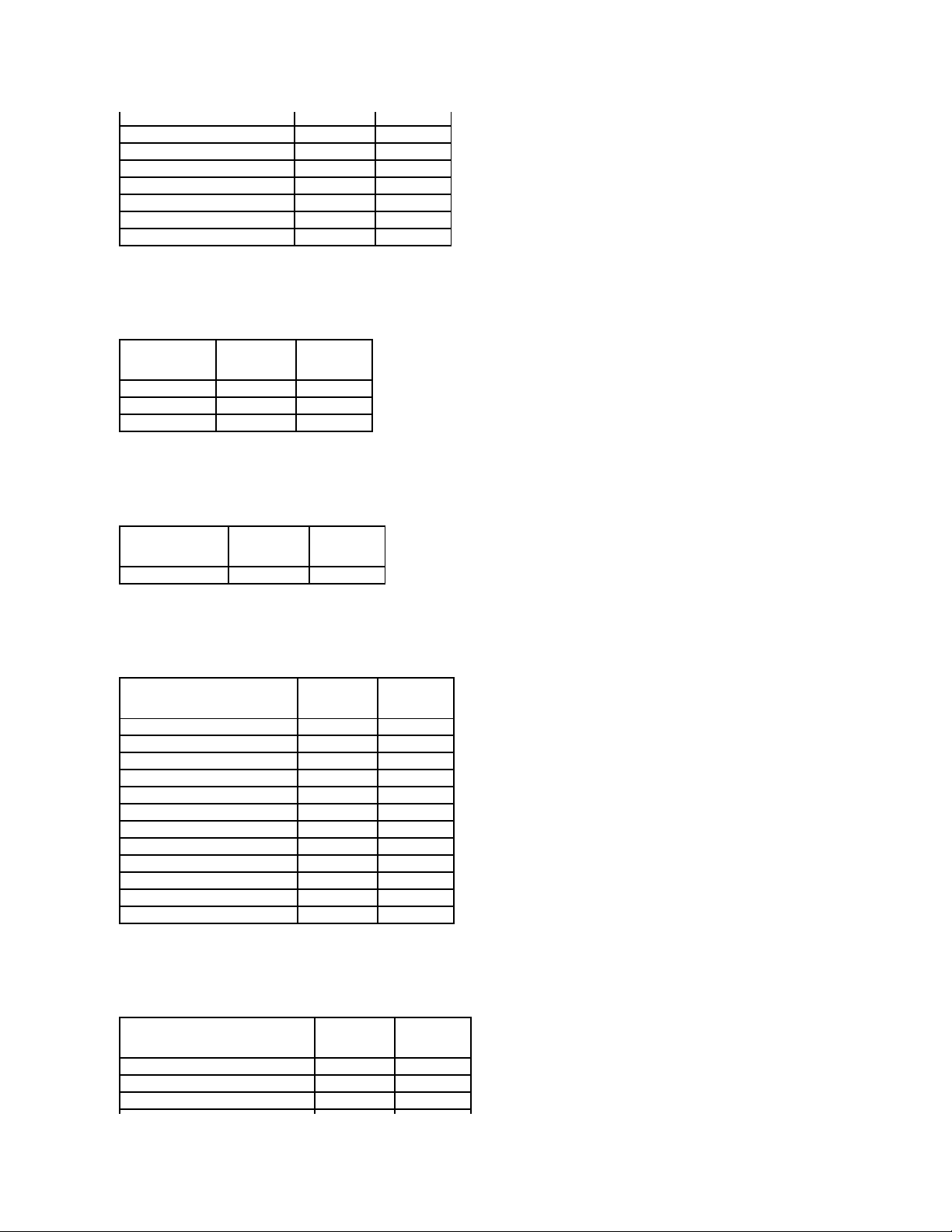
Connector Tasks
Table A-12.ConnectorTasksSupportedbythePERC3/Si,3/Di,CERCSATA1.5/2s,andCERCSATA1.5/6chControllers
Physical Disk Tasks
Table A-13.PhysicalDiskTasksSupportedbythePERC3/Si,3/Di,CERCSATA1.5/2s,andCERCSATA1.5/6chControllers
Virtual Disk Tasks
Table A-14.VirtualDiskTasksSupportedbythePERC3/Si,3/Di,CERCSATA1.5/2s,andCERCSATA1.5/6chControllers
Start Learn Cycle
No
No
No
No
Delay Learn Cycle
No
No
No
No Connector Task Name
PERC 3/SI
PERC 3/DI
CERC SATA 2S
CERC SATA 6ch
Connector Rescan
Yes
Yes
Yes
Yes Physical Disk Task Name
PERC 3/SI
PERC 3/DI
CERC SATA 2S
CERC SATA 6ch
Blink/Unblink
Yes
Yes
No
No
Assign and Unassign Global Hot Spare
Yes
Yes
No
Yes
Prepare to Remove
Yes
Yes
No
No
Offline
No
No
No
No
Online
No
No
No
No
Initialize
Yes
Yes
Yes
Yes
Rebuild
No
No
Yes
No
Cancel Rebuild
No
No
No
No
Remove Dead Disk Segments
Yes
Yes
No
Yes
Format Disk
No
No
No
No
Clear
No
No
No
No
Cancel Clear
No
No
No
No Virtual Disk Task Name
PERC 3/SI
PERC 3/DI
CERC SATA 2S
CERC SATA 6ch
Assign and Unassign Dedicated Hot Spare
Yes
Yes
No
Yes
Create Virtual Disk
Yes
Yes
Yes
Yes
Create Virtual Disk Advanced Wizard
Yes
Yes
Yes
Yes
Create Virtual Disk Express Wizard
Yes
Yes
Yes
Yes
Rename
Yes
Yes
Yes
Yes
Blink/Unblink
Yes
Yes
No
No
Reconfigure
Yes
Yes
No
Yes
Change Policy
Yes
Yes
No
Yes
Split Mirror
Yes
Yes
No
Yes
Unmirror
Yes
Yes
No
Yes
Delete Last Virtual Disk
Yes
Yes
Yes
Yes
Delete (any) Virtual Disk
Yes
Yes
No
Yes
Check Consistency
Yes
Yes
Yes
Yes
Cancel Check Consistency
Yes
Yes
Yes
Yes
Pause Check Consistency
Yes
Yes
No
Yes
Resume Check Consistency
Yes
Yes
No
Yes
Cancel Background Initialization (BGI)
No
No
No
No
Format Virtual Disk
Yes
Yes
No
Yes
Cancel Format Virtual Disk
No
No
No
No
Restore Dead Disk Segments
Yes
Yes
No
Yes
Page 8
Virtual Disk Specifications
Table A-15.VirtualDiskSpecificationsforthePERC3/Si,3/Di,CERCSATA1.5/2s,andCERCSATA1.5/6chControllers
Supported RAID Levels
Table A-16.RAIDLevelsSupportedbythePERC3/Si,3/Di,CERCSATA1.5/2s,andCERCSATA1.5/6chControllers
Read, Write, and Disk Cache Policy
Table A-17.Read,Write,andCachePolicySupportedbythePERC3/Si,3/Di,CERCSATA1.5/2s,andCERCSATA1.5/6chControllers
Initialize Virtual Disk
No
No
No
No
Fast Initialize Virtual Disk
No
No
No
No
Slow Initialize Virtual Disk
No
No
No
No
Cancel Initialize Virtual Disk
No
No
No
No Virtual Disk Specification
PERC 3/SI
PERC 3/DI
CERC SATA 2S
CERC SATA 6ch
Maximum Number of Virtual Disks per Controller
24
24 1 10
Minimum Virtual Disk Size
100MB
100MB
100MB
100MB
Maximum Virtual Disk Size
2TB
2TB
2TB
2TB
Maximum Number of Spans per Virtual Disk
16
16 1 16
Maximum Number of Physical Disks per Span
2 2 2 2 Minimum Stripe Size
8k
8k
16k
8k
Maximum Stripe Size
64k
64k
64k
64k
Maximum Number of Virtual Disks per Disk Group
10
10 1 9
Maximum Number of Physical Disks that Can Be Concatenated
1 1 1 1 Maximum Number of Physical Disks in a RAID 0
48
48 2 48
Maximum Physical Disks in a RAID 1
2 2 2 2 Maximum Number of Physical Disks in a RAID 5
16
16
NA
16
Maximum Number of Physical Disks in a RAID 10
32
32
NA
32
Maximum Number of Physical Disks in a RAID 50
NA
NA
NA
NA
Minimum Number of Physical Disks that Can Be Concatenated
1 1 1 1 Minimum Number of Physical Disks in a RAID 0
1 1 1 1 Minimum Number of Physical Disks in a RAID 1
2 2 2 2 Minimum Number of Physical Disks in a RAID 5
3 3 NA 3 Minimum Number of Physical Disks in a RAID 10
4 4 NA 4 Minimum Number of Physical Disks in a RAID 50
NA
NA
NA
NA
Maximum number of physical disks in a RAID 6
NA
NA
NA
NA
Maximum number of physical disks in a RAID 60
NA
NA
NA
NA
Minimum number of physical disks in a RAID 6
NA
NA
NA
NA
Minimum number of physical disks in a RAID 60
NA
NA
NA
NA RAID Level
PERC 3/SI
PERC 3/DI
CERC SATA 2S
CERC SATA 6ch
Concatenation
Yes
Yes
Yes
Yes
RAID 0
Yes
Yes
Yes
Yes
RAID 1
Yes
Yes
Yes
Yes
RAID 5
Yes
Yes
No
Yes
RAID 10
Yes
Yes
No
Yes
RAID 50
No
No
No
No
RAID 6
No
No
No
No
RAID 60
No
No
No
No
Page 9
Enclosure Support
Table A-18.EnclosureSupportonthePERC3/Si,3/Di,CERCSATA1.5/2s,andCERCSATA1.5/6chControllers
Supported Features on the PERC 5/E, PERC 5/i, PERC 6/E, PERC 6/I, PERC 6/I
Modular, and CERC 6/I Controllers
This section identifies the controller-supported features and whether or not an enclosure can be attached to the controller.
l "Controller Tasks"
l "Battery Tasks"
l "Connector Tasks"
l "Physical Disk Tasks"
l "Virtual Disk Tasks"
l "Virtual Disk Specifications"
l "Supported RAID Levels"
l "Read, Write, Cache and Disk Cache Policy"
l "Enclosure Support"
For enclosure-supported tasks, see "Enclosure and Backplane Features."
Controller Tasks
Table A-19.ControllerTasksSupportedonthePERC5/E,PERC5/i,PERC6/E,PERC6/I,PERC6/IModular,andCERC6/IControllers
Read, Write, and Cache Policy
PERC 3/SI
PERC 3/DI
CERC SATA 2S
CERC SATA 6ch
Cache settings
Yes
Yes
No
Yes
Read Policy
Yes
Yes
No
Yes
Read Ahead (Enabled)
Yes
Yes
No
Yes
Adaptive Read Ahead
No
No
No
No
No Read Ahead (Disabled)
Yes
Yes
Yes
Yes
Write Policy
Yes
Yes
No
Yes
Write Back (Enabled)
No
No
No
No
Write Through (Disabled)
Yes
Yes
Yes
Yes
Force Write Back (Enabled Always)
No
No
No
No
Write Cache Enabled Protected
Yes
Yes
No
Yes
Cache Policy
No
No
No
No
Cache I/O
No
No
No
No
Direct I/O
No
No
No
No Enclosure Support
PERC 3/SI
PERC 3/DI
CERC SATA 2S
CERC SATA 6ch
Can an enclosure be attached to this controller?
No
Yes
No
No
Controller Task Name
PERC 5/E
PERC 5/i
PERC 6/E
PERC 6/I
PERC 6/I Modular
CERC
6/I
Enable Alarm
Yes
No
Yes
NA
NA
NA
Disable Alarm
Yes
No
Yes
NA
NA
NA
Quiet Alarm
Yes
No
Yes
NA
NA
NA
Test Alarm
Yes
No
Yes
NA
NA
NA
Reset configuration
Yes
Yes
Yes
Yes
Yes
Yes
Set Rebuild Rate
Yes
Yes
Yes
Yes
Yes
Yes
Set Background Initialization
Rate
Yes
Yes
Yes
Yes
Yes
Yes
Set Check Consistency Rate
Yes
Yes
Yes
Yes
Yes
Yes
Set Reconstruct Rate
Yes
Yes
Yes
Yes
Yes
Yes
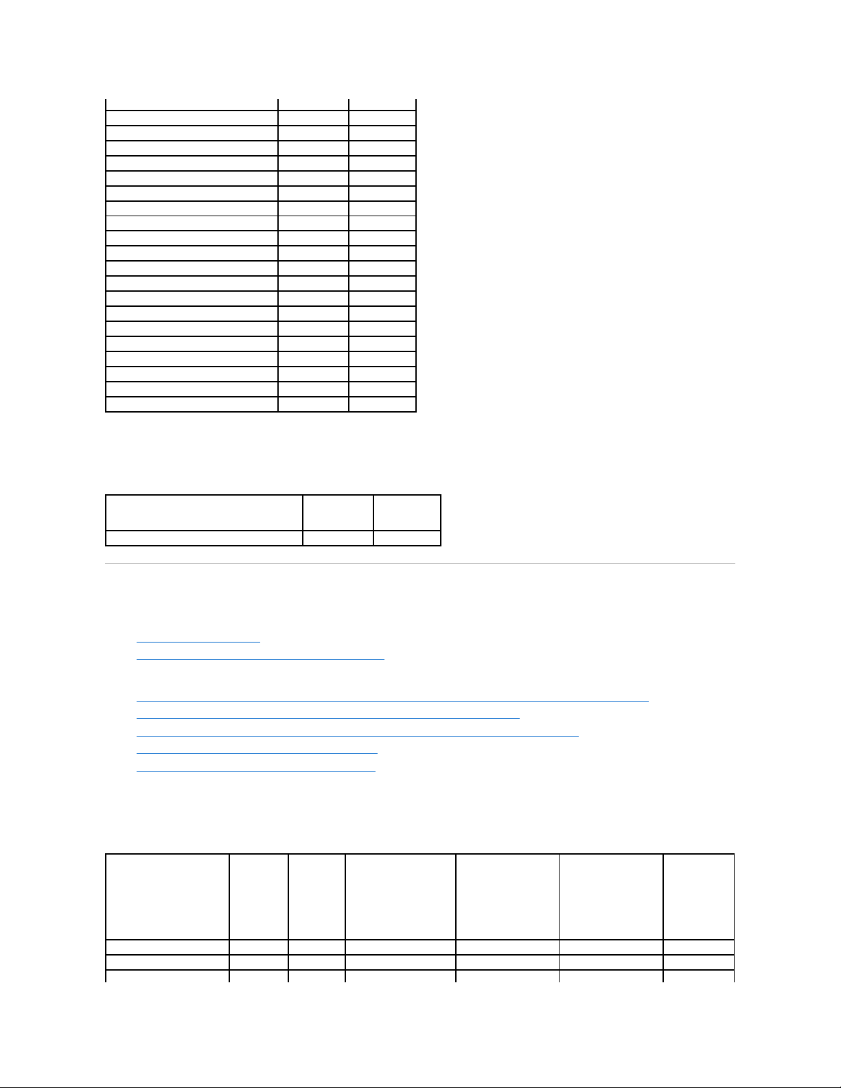
Page 10
Battery Tasks
Table A-20. Battery Tasks Supported on the PERC 5/E, PERC 5/i, PERC 6/E, PERC 6/I, PERC 6/I, PERC 6/I Modular, and CERC 6/I
Controllers
Connector Tasks
Table A-21. Connector Tasks Supported by the PERC 5/E, PERC 5/i, PERC 6/E, PERC 6/I, PERC 6/I, Modular, and CERC 6/I Controllers
Physical Disk Tasks
Table A-22. Physical Disk Tasks Supported by the PERC 5/E, PERC 5/i, PERC 6/E, PERC 6/I, PERC 6/I Modular, and CERC 6/I Controllers
Rescan Controller
No
No
No
No
No
No
Create Virtual Disk
Yes
Yes
Yes
Yes
Yes
Yes
Export Log File
Yes
Yes
Yes
Yes
Yes
Yes
Clear Foreign Configuration
Yes
Yes
Yes
Yes
Yes
Yes
Import Foreign Configuration
Yes
Yes
Yes
Yes
Yes
Yes
Import/Recover Foreign
Configuration
Yes with firmware
5.1.x or greater.
Yes with firmware
5.1.x or greater.
Yes
Yes
Yes
Yes
Set Patrol Read Mode
Yes
Yes
Yes
Yes
Yes
Yes
Start Patrol Read
Yes
Yes
Yes
Yes
Yes
Yes
Stop Patrol Read
Yes
Yes
Yes
Yes
Yes
Yes
Replace Member
No
No
Yes with firmware
6.1 and later
Yes with firmware
6.1 and later
Yes with firmware
6.1 and later
No
Foreign Configuration
No
No
Yes with firmware
6.1 and later
Yes with firmware
6.1 and later
Yes with firmware
6.1 and later
No
Import Preview of Foreign
Configuration
No
No
Yes with firmware
6.1 and later
Yes with firmware
6.1 and later
Yes with firmware
6.1 and later
No
Hot-plug of Enclosures
No
No
Yes with firmware
6.1 and later
No
No
No
Change Controller
Properties
No
No
Yes with firmware
6.1 and later
Yes with firmware
6.1 and later
Yes with firmware
6.1 and later
No
Intelligent Mirroring
No
No
Yes with firmware
6.1 and later
Yes with firmware
6.1 and later
Yes with firmware
6.1 and later
No
Redundant Path
Configuration
No
No
Yes with firmware
6.1 and later
No
No
No
Disk Cache Policy
Yes
Yes
Yes
Yes
Yes
No
Managing Preserved Cache
No
No
Yes with firmware
6.1 and later
Yes with firmware
6.1 and later
Yes with firmware
6.1 and later
No
Battery Task Name
PERC 5/E
PERC 5/i
PERC 6/E
PERC 6/I
PERC 6/I Modular
CERC 6/I
Recondition Battery
No
No
No
No
No
No
Start Learn Cycle
Yes
Yes
Yes
Yes
Yes
No
Delay Learn Cycle
Yes
Yes
Yes
Yes
Yes
No Connector Task Name
PERC 5/E
PERC 5/I
PERC 6/E
PERC 6/I
PERC 6/I Modular
CERC 6/I
Connector Rescan
No
No
No
No
No
No
Physical Disk Task Name
PERC
5/E
PERC
5/I
PERC 6/E
PERC 6/I
PERC 6/I Modular
CERC
6/I
Blink/Unblink
Yes
Yes
Yes
Yes
Yes
Yes
Assign and Unassign Global Hot
Spare
Yes
Yes
Yes
Yes
Yes
Yes
Prepare to Remove
No
No
No
No
No
No
Offline
Yes
Yes
Yes
Yes
Yes
Yes
Online
Yes
Yes
Yes
Yes
Yes
Yes
Initialize
No
No
No
No
No
No
Page 11
Virtual Disk Tasks
Table A-23. Virtual Disk Tasks Supported by the PERC 5/E, PERC 5/i, PERC 6/E, PERC 6/I, PERC 6/I Modular, and CERC 6/I Controllers
Virtual Disk Specifications
Table A-24. Virtual Disk Specifications for the PERC 5/E, PERC 5/i, PERC 6/E, PERC 6/I, PERC 6/I Modular, and CERC 6/I Controllers
Rebuild
Yes
Yes
Yes
Yes
Yes
Yes
Cancel Rebuild
Yes
Yes
Yes
Yes
Yes
Yes
Remove Dead Disk Segments
No
No
No
No
No
No
Format Disk
No
No
No
No
No
No
Clear
Yes
Yes
Yes
Yes
Yes
Yes
Cancel Clear
Yes
Yes
Yes
Yes
Yes
Yes
Cancel Replace Member
No
No
Yes with firmware 6.1 and
later
Yes with firmware 6.1 and
later
Yes with firmware 6.1 and
later
No Virtual Disk Task Name
PERC
5/E
PERC
5/I
PERC 6/E
PERC 6/I
PERC 6/I Modular
CERC
6/I
Assign and Unassign Dedicated Hot
Spare
Yes
Yes
Yes
Yes
Yes
Yes
Create Virtual Disk
Yes
Yes
Yes
Yes
Yes
Yes
Create Virtual Disk Advanced Wizard
Yes
Yes
Yes
Yes
Yes
Yes
Create Virtual Disk Express Wizard
Yes
Yes
Yes
Yes
Yes
Yes
Rename
Yes
Yes
Yes
Yes
Yes
Yes
Blink/Unblink
Yes
Yes
Yes
Yes
Yes
Yes
Reconfigure
Yes
Yes
Yes
Yes
Yes
Yes
Change Policy
Yes
Yes
Yes
Yes
Yes
Yes
Split Mirror
No
No
No
No
No
No
Unmirror
No
No
No
No
No
No
Delete Last Virtual Disk
Yes
Yes
Yes
Yes
Yes
Yes
Delete (any) Virtual Disk
Yes
Yes
Yes
Yes
Yes
Yes
Check Consistency
Yes
Yes
Yes
Yes
Yes
Yes
Cancel Check Consistency
Yes
Yes
Yes
Yes
Yes
Yes
Pause Check Consistency
No
No
No
No
No
No
Resume Check Consistency
No
No
No
No
No
No
Cancel Background Initialization
(BGI)
Yes
Yes
Yes
Yes
Yes
Yes
Format Virtual Disk
No
No
No
No
No
No
Cancel Format Virtual Disk
No
No
No
No
No
No
Restore Dead Disk Segments
No
No
No
No
No
No
Initialize Virtual Disk
No
No
No
No
No
No
Fast Initialize Virtual Disk
Yes
Yes
Yes
Yes
Yes
Yes
Slow Initialize Virtual Disk
Yes
Yes
Yes
Yes
Yes
Yes
Cancel Initialize Virtual Disk
Yes
Yes
Yes
Yes
Yes
Yes
Replace Member
No
No
Yes with firmware 6.1 and
later
Yes with firmware 6.1 and
later
Yes with firmware 6.1 and
later
No
Virtual Disk Specification
PERC 5/E
PERC 5/I
PERC 6/E
PERC 6/I
PERC 6/I Modular
CERC 6/I
Maximum Number of Virtual Disks per Controller
64
64
64
64
64
64
Minimum Virtual Disk Size
100MB
100MB
100MB
100MB
100MB
100MB
Maximum Virtual Disk Size
None
None
None
None
None
None
Maximum Number of Spans per Virtual Disk
8 8 8 8 8 8 Maximum Number of Physical Disks per Span
32
32
32
32
32
32
Minimum Stripe Size
8k
8k
8k
8k
8k
8k
Maximum Stripe Size
128k
128k
1MB
1MB
1MB
1MB
Maximum Number of Virtual Disks per Disk Group
16
16
16
16
16
16
Page 12
Supported RAID Levels
Table A-25. RAID Levels Supported by the PERC 5/E, PERC 5/i, PERC 6/E, PERC 6/I, PERC 6/I Modular, and CERC 6/I Controllers
Read, Write, Cache and Disk Cache Policy
Table A-26. Read, Write, and Cache Policy Supported by the PERC 5/E, PERC 5/i, PERC 6/E, PERC 6/I, PERC 6/I Modular, and CERC 6/I
Controllers
Enclosure Support
Maximum Number of Physical Disks that Can Be Concatenated
NA
NA
NA
NA
NA
NA
Maximum Number of Physical Disks in a RAID 0
32
32
32
32
32
32
Maximum Physical Disks in a RAID 1
2 2 2 2 2 2 Maximum Number of Physical Disks in a RAID 5
32
32
32
32
32
32
Maximum Number of Physical Disks in a RAID 10
16
16
256
with firmware version 6.1
16
16
16
Maximum Number of Physical Disks in a RAID 50
256
256
256
256
256
256
Minimum Number of Physical Disks that Can Be Concatenated
NA
NA
NA
NA
NA
NA
Minimum Number of Physical Disks in a RAID 0
1 1 1 1 1 1 Minimum Number of Physical Disks in a RAID 1
2 2 2 2 2 2 Minimum Number of Physical Disks in a RAID 5
3 3 3 3 3 3 Minimum Number of Physical Disks in a RAID 10
4 4 4 4 4 4 Minimum Number of Physical Disks in a RAID 50
6 6 6 6 6 6 Maximum number of physical disks in a RAID 6
NA
NA
32
32
32
32
Maximum number of physical disks in a RAID 60
NA
NA
256
256
256
256
Minimum number of physical disks in a RAID 6
NA
NA 4 4 4 4
Minimum number of physical disks in a RAID 60
NA
NA 8 8 8 8 RAID Level
PERC 5/E
PERC 5/I
PERC 6/E
PERC 6/I
PERC 6/I Modular
CERC 6/I
Concatenation
No
No
No
No
No
No
RAID 0
Yes
Yes
Yes
Yes
Yes
Yes
RAID 1
Yes
Yes
Yes
Yes
Yes
Yes
RAID 5
Yes
Yes
Yes
Yes
Yes
Yes
RAID 10
Yes
Yes
Yes
Yes
Yes
Yes
RAID 50
Yes
Yes
Yes
Yes
Yes
Yes
RAID 6
No
No
Yes
Yes
Yes
Yes
RAID 60
No
No
Yes
Yes
Yes
Yes Read, Write, and Cache Policy
PERC 5/E
PERC 5/I
PERC 6/E
PERC 6/I
PERC 6/I Modular
CERC 6/I
Cache settings
Yes
Yes
Yes
Yes
Yes
Yes
Read Policy
Yes
Yes
Yes
Yes
Yes
Yes
Read Ahead (Enabled)
Yes
Yes
Yes
Yes
Yes
Yes
Adaptive Read Ahead
Yes
Yes
Yes
Yes
Yes
Yes
No Read Ahead (Disabled)
Yes
Yes
Yes
Yes
Yes
Yes
Write Policy
Yes
Yes
Yes
Yes
Yes
Yes
Write Back (Enabled)
Yes
Yes
Yes
Yes
Yes
Yes
Write Through (Disabled)
Yes
Yes
Yes
Yes
Yes
Yes
Force Write Back (Enabled Always)
Yes
Yes
Yes
Yes
Yes
Yes
Write Cache Enabled Protected
No
No
No
No
No
No
Cache Policy
No
No
No
No
No
No
Disk Cache Policy
Yes
Yes
Yes
Yes
Yes
No
Cache I/O
No
No
No
No
No
No
Direct I/O
No
No
No
No
No
No
Page 13
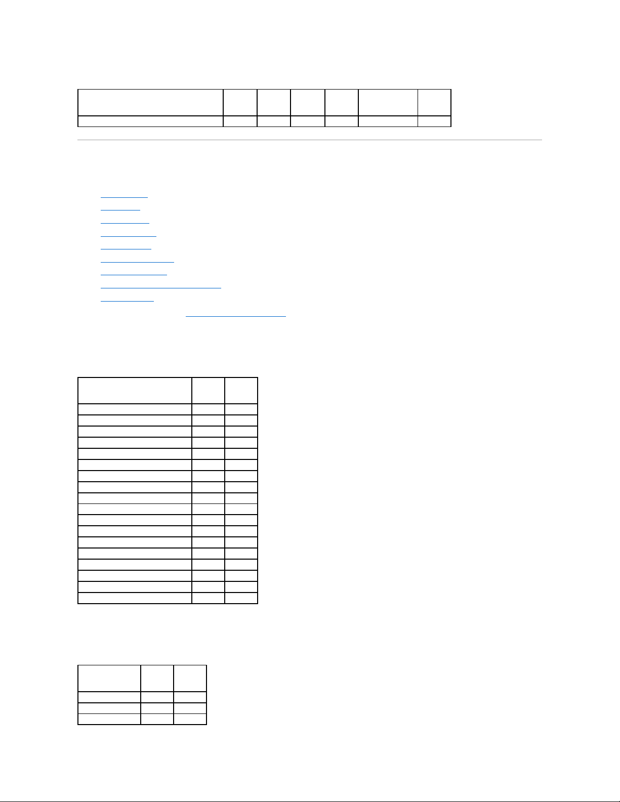
Table A-27. Enclosure Support on the PERC 5/E, PERC 5/i, PERC 6/E, PERC 6/I, PERC 6/I, Modular, and CERC 6/I Controllers
Supported Features on the SAS 5/iR and SAS 6/iR Controllers
This section identifies the controller-supported features and whether or not an enclosure can be attached to the controller.
l "Controller Tasks"
l "Battery Tasks"
l "Connector Tasks"
l "Physical Disk Tasks"
l "Virtual Disk Tasks"
l "Virtual Disk Specifications"
l "Supported RAID Levels"
l "Read, Write, Cache and Disk Cache Policy"
l "Enclosure Support"
For enclosure-supported tasks, see "Enclosure and Backplane Features."
Controller Tasks
Table A-28.ControllerTasksSupportedontheSAS5/iRandSAS6/iRControllers
Battery Tasks
Table A-29.BatteryTasksSupportedontheSAS5/iRandSAS6/iRController
Enclosure Support
PERC 5/E
PERC 5/I
PERC 6/E
PERC 6/I
PERC 6/I Modular
CERC 6/I
Can an enclosure be attached to this controller?
Yes
No
Yes
No
No
No Controller Task Name
SAS 5/iR
SAS 6/iR
Enable Alarm
No
No
Disable Alarm
No
No
Quiet Alarm
No
No
Test Alarm
No
No
Reset configuration
No
Yes
Set Rebuild Rate
No
No
Set Background Initialization Rate
No
No
Set Check Consistency Rate
No
No
Set Reconstruct Rate
No
No
Rescan Controller
No
No
Create Virtual Disk
No
No
Export Log File
No
No
Clear Foreign Configuration
Yes
Yes
Import Foreign Configuration
No
No
Import/Recover Foreign Configuration
No
No
Set Patrol Read Mode
No
No
Start Patrol Read
No
No
Stop Patrol Read
No
No Battery Task Name
SAS 5/iR
SAS 6/iR
Recondition Battery
No
No
Start Learn Cycle
No
No
Delay Learn Cycle
No
No
Page 14
Connector Tasks
Table A-30.ConnectorTasksSupportedontheSAS5/iRandSAS6/iRControllers
Physical Disk Tasks
Table A-31.PhysicalDiskTasksSupportedontheSAS5/iRandSAS6/iRControllers
Virtual Disk Tasks
Table A-32. Virtual Disk Tasks Supported by the SAS 5/iR and SAS 6/iR Controllers
Connector Task Name
SAS 5/IR
SAS 6/iR
Connector Rescan
No
No Physical Disk Task Name
SAS 5/IR
SAS 6/iR
Blink/Unblink
Yes
Task only available when an enclosure or backplane and LEDs on the physical
disks are present.
Yes
Assign and Unassign Global Hot
Spare
No
Supports up to two global hot spares
Prepare to Remove
No
No
Offline
No
No
Online
No
No
Initialize
No
No
Rebuild
No
NA.
Rebuild automatically initiated by the
controller.
Cancel Rebuild
No
No
Remove Dead Disk Segments
No
No
Format Disk
No
No
Clear
No
No
Cancel Clear
No
No Virtual Disk Task Name
SAS 5/IR
SAS 6/iR
Assign and Unassign Dedicated Hot Spare
No
No
Create Virtual Disk
No
Yes
Create Virtual Disk Advanced Wizard
No
Yes
Create Virtual Disk Express Wizard
No
No
Rename
No
No
Blink/Unblink
Yes
Yes
Reconfigure
No
No
Change Policy
No
No
Split Mirror
No
No
Unmirror
No
No
Delete Last Virtual Disk
No
Yes
Delete (any) Virtual Disk
No
Yes
Check Consistency
No
No
Cancel Check Consistency
No
No
Pause Check Consistency
No
No
Page 15
Supported RAID Levels
Table A-33. RAID Levels Supported by the SAS 5/iR and SAS 6/iR Controllers
Virtual Disk Specifications
Table A-34. Virtual Disk Specifications for the SAS 5/iR and SAS 6/iR Controllers
Read, Write, Cache and Disk Cache Policy
Table A-35. Read, Write, and Cache Policy Supported by the SAS 5/iR and SAS 6/iR Controllers
Resume Check Consistency
No
No
Cancel Background Initialization (BGI)
No
No
Format Virtual Disk
No
No
Cancel Format Virtual Disk
No
No
Restore Dead Disk Segments
No
No
Initialize Virtual Disk
No
No
Fast Initialize Virtual Disk
No
No
Slow Initialize Virtual Disk
No
No
Cancel Initialize Virtual Disk
No
No RAID Level
SAS 5/IR
SAS 6/iR
RAID 0
Yes
Yes
RAID 1
Yes
Yes Virtual Disk Specification
SAS 5/IR
SAS 6/iR
Maximum Number of Virtual Disks per Controller
2 2 Minimum Virtual Disk Size
Max
Max
Maximum Virtual Disk Size
2TB
None
Maximum Number of Spans per Virtual Disk
1 1 Maximum Number of Physical Disks per Span
4
10
Minimum Stripe Size
64k
64k
Maximum Stripe Size
64k
64k
Maximum Number of Virtual Disks per Disk Group
1 1 Maximum Number of Physical Disks that Can Be Concatenated
NA
NA
Maximum Number of Physical Disks in a RAID 0
4 8 Maximum Physical Disks in a RAID 1
2 2 Maximum Number of Physical Disks in a RAID 5
NA
NA
Maximum Number of Physical Disks in a RAID 10
NA
NA
Maximum Number of Physical Disks in a RAID 50
NA
NA
Minimum Number of Physical Disks that Can Be Concatenated
NA
NA
Minimum Number of Physical Disks in a RAID 0
2 2 Minimum Number of Physical Disks in a RAID 1
2 2 Minimum Number of Physical Disks in a RAID 5
NA
NA
Minimum Number of Physical Disks in a RAID 10
NA
NA
Minimum Number of Physical Disks in a RAID 50
NA
NA
Maximum number of physical disks in a RAID 6
NA
NA
Maximum number of physical disks in a RAID 60
NA
NA
Minimum number of physical disks in a RAID 6
NA
NA
Minimum number of physical disks in a RAID 60
NA
NA Read, Write, and Cache Policy
SAS 5/IR
SAS 6/iR
Page 16
Enclosure Support
Table A-36. Enclosure Support on the SAS 5/iR and SAS 6/iR Controllers
Supported Features on the PERC S100 and S300 Controllers
This section identifies the controller-supported features and whether or not an enclosure can be attached to the controller.
l "Controller Tasks"
l "Physical Disk Tasks"
l "Virtual Disk Tasks"
l "Virtual Disk Specifications"
l "Supported RAID Levels"
l "Read, Write, Cache and Disk Cache Policy"
l "Enclosure Support"
Controller Tasks
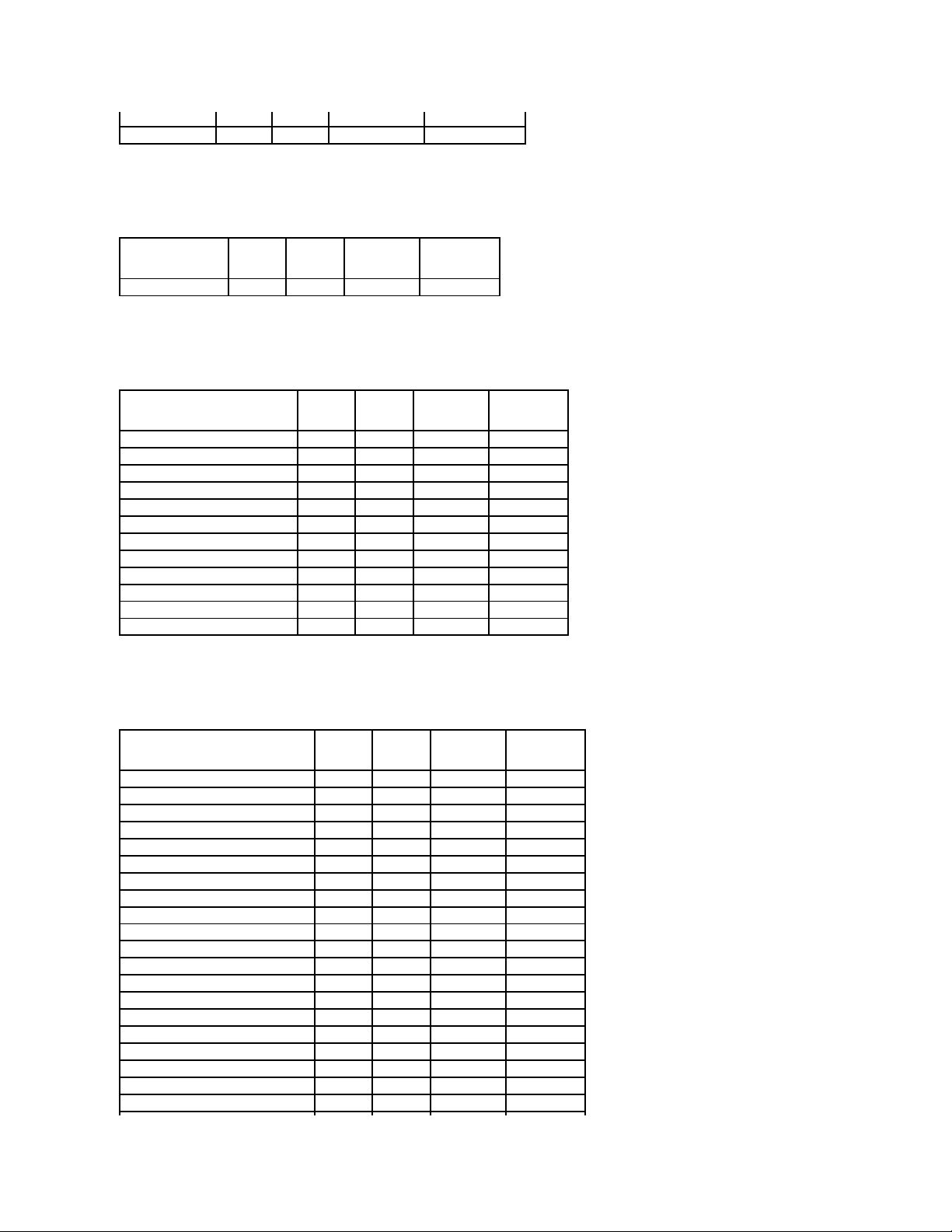
Table A-37. Controller Tasks Supported on the PERC S100 and S300 Controllers
Physical Disk Tasks
Table A-38. Physical Disk Tasks Supported by the PERC S100 and S300 Controllers
Virtual Disk Tasks
Cache settings
No
No
Read Policy
Yes
Yes
Read Ahead (Enabled)
No
No
Adaptive Read Ahead
No
No
No Read Ahead (Disabled)
Yes
Yes
Write Policy
Yes
Yes
Write Back
No
No
Write Through
Yes
Yes
Force Write Back (Enabled Always)
No
No
Write Cache Enabled Protected
No
No
Cache Policy
No
No
Disk Cache Policy
No
No
Cache I/O
No
No
Direct I/O
No
No Enclosure Support
SAS 5/IR
SAS 6/iR
Can an enclosure be attached to this controller?
No
No Controller Task Name
PERC S100
PERC S300
Create Virtual Disk
Yes
Yes Physical Disk Task Name
PERC S100
PERC S300
Blink/Unblink
No
Yes
Assign and Unassign Global Hot Spare
Yes
Yes
Page 17
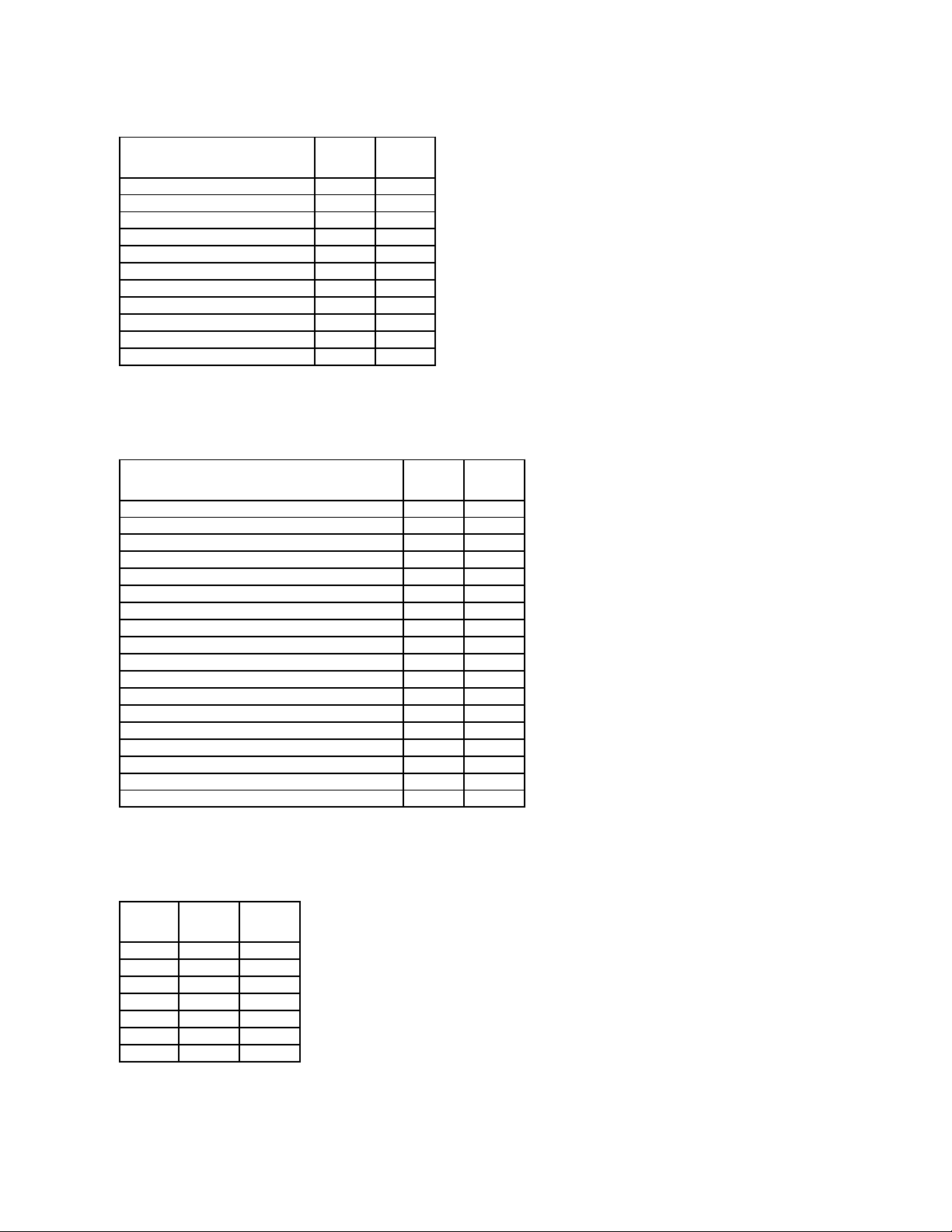
Table A-39. Virtual Disk Tasks Supported by the PERC S100 and S300 Controllers
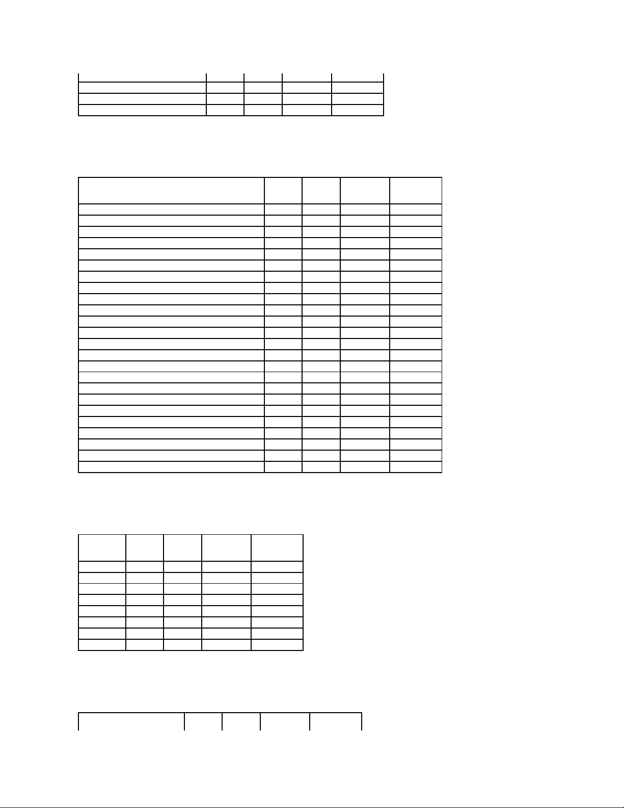
Virtual Disk Specifications
Table A-40. Virtual Disk Specifications for the PERC S100 and S300 Controllers
Supported RAID Levels
Table A-41. RAID Levels Supported by the PERC S100 and S300 Controllers
Read, Write, Cache and Disk Cache Policy
Virtual Disk Task Name
PERC S100
PERC S300
Assign and Unassign Dedicated Hot Spare
Yes
Yes
Create Virtual Disk
Yes
Yes
Create Virtual Disk Advanced Wizard
Yes
Yes
Create Virtual Disk Express Wizard
Yes
Yes
Rename
Yes
Yes
Blink/Unblink
No
Yes
Reconfigure
Yes
Yes
Change Policy
Yes
Yes
Delete Last Virtual Disk
Yes
Yes
Delete (any) Virtual Disk
Yes
Yes
Check Consistency
Yes
Yes Virtual Disk Specification
PERC S100
PERC S300
Maximum Number of Virtual Disks per Controller
8 8 Minimum Virtual Disk Size
100MB
100MB
Maximum Virtual Disk Size
None
None
Maximum Number of Spans per Virtual Disk
NA
NA
Maximum Number of Physical Disks per Span
NA
NA
Minimum Stripe Size
64k
64k
Maximum Stripe Size
64k
64k
Maximum Number of Virtual Disks per Physical Disk
8 8 Maximum Number of Physical Disks that Can Be Concatenated
NA
NA
Maximum Number of Physical Disks in a RAID 0
8 8 Maximum Physical Disks in a RAID 1
2 2 Maximum Number of Physical Disks in a RAID 5
8 8 Maximum Number of Physical Disks in a RAID 10
4 4 Minimum Number of Physical Disks that Can Be Concatenated
NA
NA
Minimum Number of Physical Disks in a RAID 0
2 2 Minimum Number of Physical Disks in a RAID 1
2 2 Minimum Number of Physical Disks in a RAID 5
3 3 Minimum Number of Physical Disks in a RAID 10
4
4 RAID Level
PERC S100
PERC S300
RAID 0
Yes
Yes
RAID 1
Yes
Yes
RAID 5
Yes
Yes
RAID 10
Yes
Yes
RAID 50
No
No
RAID 6
No
No
RAID 60
No
No
Page 18
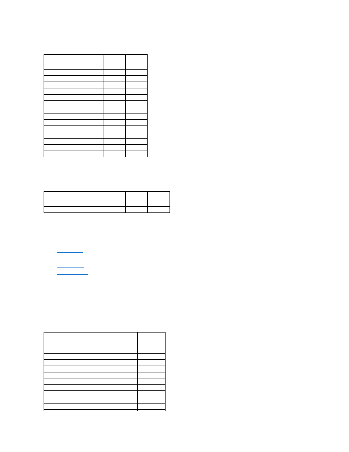
Table A-42. Read, Write, and Cache Policy Supported by the PERC S100 and S300 Controllers
Enclosure Support
Table A-43. Enclosure Support on the PERC S100 and S300 Controllers
Supported Features on the Non-RAID Controllers
This section identifies the controller-supported features and whether or not an enclosure can be attached to the controller.
l "Controller Tasks"
l "Battery Tasks"
l "Connector Tasks"
l "Physical Disk Tasks"
l "Virtual Disk Tasks"
l "Enclosure Support"
For enclosure-supported tasks, see "Enclosure and Backplane Features."
Controller Tasks
Table A-44. Controller Tasks Supported on the Non-RAIDControllers
Read, Write, and Cache Policy
PERC S100
PERC S300
Cache settings
Yes
Yes
Read Policy
Yes
Yes
Read Ahead (Enabled)
Yes
Yes
Adaptive Read Ahead
No
No
No Read Ahead (Disabled)
Yes
Yes
Write Policy
Yes
Yes
Write Back (Enabled)
Yes
Yes
Write Through (Disabled)
Yes
Yes
Force Write Back (Enabled Always)
No
No
Write Cache Enabled Protected
No
No
Cache Policy
No
No
Disk Cache Policy
No
No
Cache I/O
No
No
Direct I/O
No
No Enclosure Support
PERC S100
PERC S300
Can an enclosure be attached to this controller?
No
No Controller Task Name
Non-RAID SCSI
Non-RAID SAS
Enable Alarm
No
No
Disable Alarm
No
No
Quiet Alarm
No
No
Test Alarm
No
No
Reset configuration
No
No
Set Rebuild Rate
No
No
Set Background Initialization Rate
No
No
Set Check Consistency Rate
No
No
Set Reconstruct Rate
No
No
Rescan Controller
No
No
Page 19
Battery Tasks
Table A-45. Battery Tasks Supported on the Non-RAIDControllers
Connector Tasks
Table A-46. Connector Tasks Supported on the Non-RAIDControllers
Physical Disk Tasks
Table A-47. Physical Disk Tasks Supported on the Non-RAIDControllers
Virtual Disk Tasks
Table A-48. Virtual Disk Tasks Supported by the Non-RAIDControllers
Create Virtual Disk
No
No
Export Log File
No
No
Clear Foreign Configuration
No
No
Import Foreign Configuration
No
No
Import/Recover Foreign Configuration
No
No
Set Patrol Read Mode
No
No
Start Patrol Read
No
No
Stop Patrol Read
No
No Battery Task Name
Non-RAID SCSI
Non-RAID SAS
Recondition Battery
No
No
Start Learn Cycle
No
No
Delay Learn Cycle
No
No Connector Task Name
Non-RAID SCSI
Non-RAID SAS
Connector Rescan
No
No Physical Disk Task Name
Non-RAID SCSI
Non-RAID SAS
Blink/Unblink
Yes
Yes
Assign and Unassign Global Hot Spare
No
No
Prepare to Remove
No
No
Offline
No
No
Online
No
No
Initialize
No
No
Rebuild
No
No
Cancel Rebuild
No
No
Remove Dead Disk Segments
No
No
Format Disk
No
No
Clear
No
No
Cancel Clear
No
No Virtual Disk Task Name
Non-RAID SCSI
Non-RAID SAS
Assign and Unassign Dedicated Hot Spare
No
No
Create Virtual Disk
No
No
Create Virtual Disk Advanced Wizard
No
No
Page 20
Enclosure Support
Table A-49. Enclosure Support on the Non-RAIDControllers
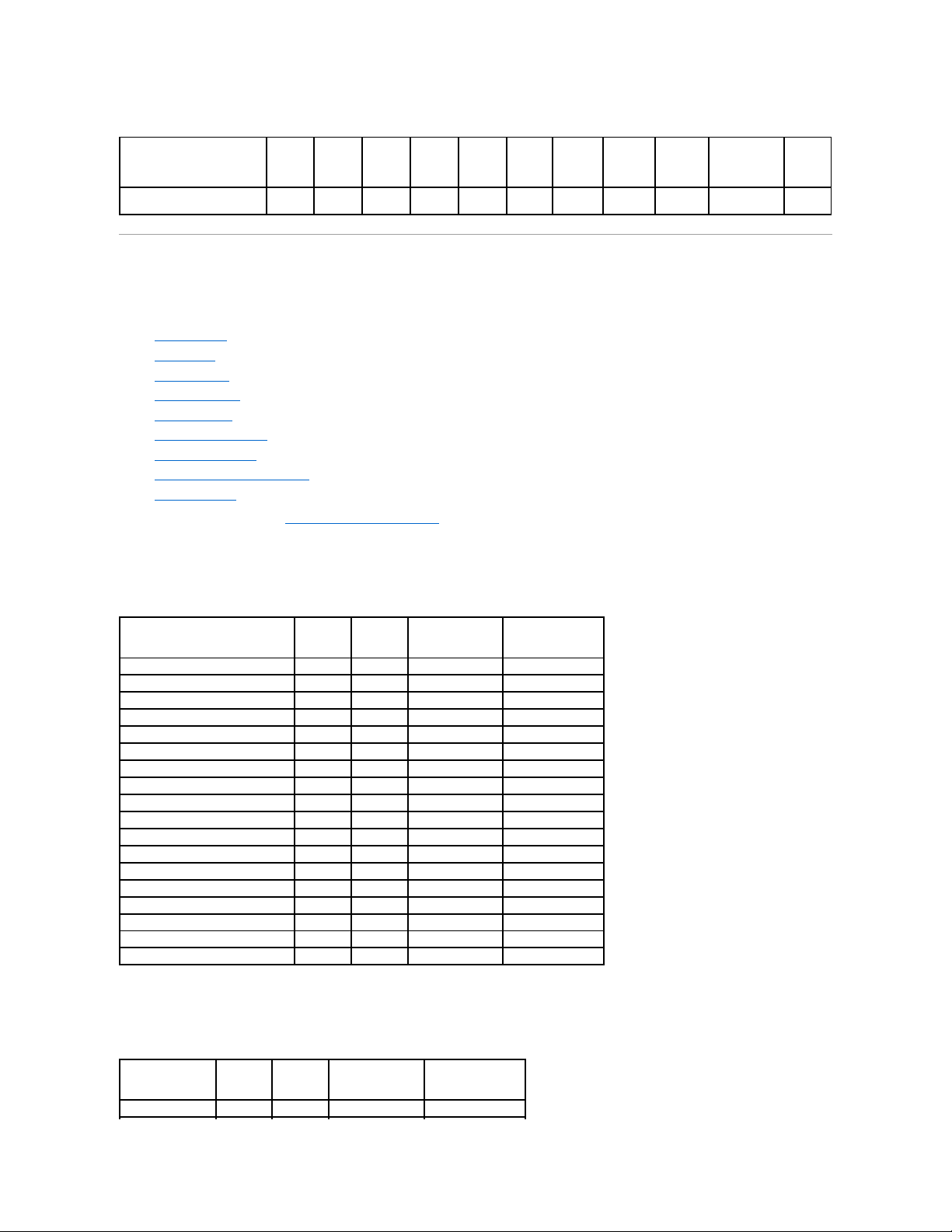
Enclosure and Backplane Features
This section identifies the features supported by the enclosure or backplane.
l "Enclosure and Backplane Tasks"
l "Enclosure and Backplane Support for Smart Thermal Shutdown"
For information on controller-supported features, see:
l "Supported Features on the PERC 3/SC, 3/DC, 3/QC, 4/SC, 4/DC, 4/Di, 4e/Si, 4e/Di, 4e/DC, CERC ATA100/4ch, and 4/IM Controllers"
l "Supported Features on the PERC 3/Si, 3/Di, CERC SATA1.5/2s, and CERC SATA1.5/6ch Controllers"
l "Supported Features on the PERC 5/E, PERC 5/i, PERC 6/E, PERC 6/I, PERC 6/I Modular, and CERC 6/I Controllers"
l "Supported Features on the SAS 5/iR and SAS 6/iR Controllers"
l "Supported Features on the PERC S100 and S300 Controllers"
Enclosure and Backplane Tasks
Table A-50.EnclosureandBackplaneTasks
Create Virtual Disk Express Wizard
No
No
Rename
No
No
Blink/Unblink
No
No
Reconfigure
No
No
Change Policy
No
No
Split Mirror
No
No
Unmirror
No
No
Delete Last Virtual Disk
No
No
Delete (any) Virtual Disk
No
No
Check Consistency
No
No
Cancel Check Consistency
No
No
Pause Check Consistency
No
No
Resume Check Consistency
No
No
Cancel Background Initialization (BGI)
No
No
Format Virtual Disk
No
No
Cancel Format Virtual Disk
No
No
Restore Dead Disk Segments
No
No
Initialize Virtual Disk
No
No
Fast Initialize Virtual Disk
No
No
Slow Initialize Virtual Disk
No
No
Cancel Initialize Virtual Disk
No
No Enclosure Support
Non-RAID SCSI
Non-RAID SAS
Can an enclosure be attached to this controller?
Yes
No
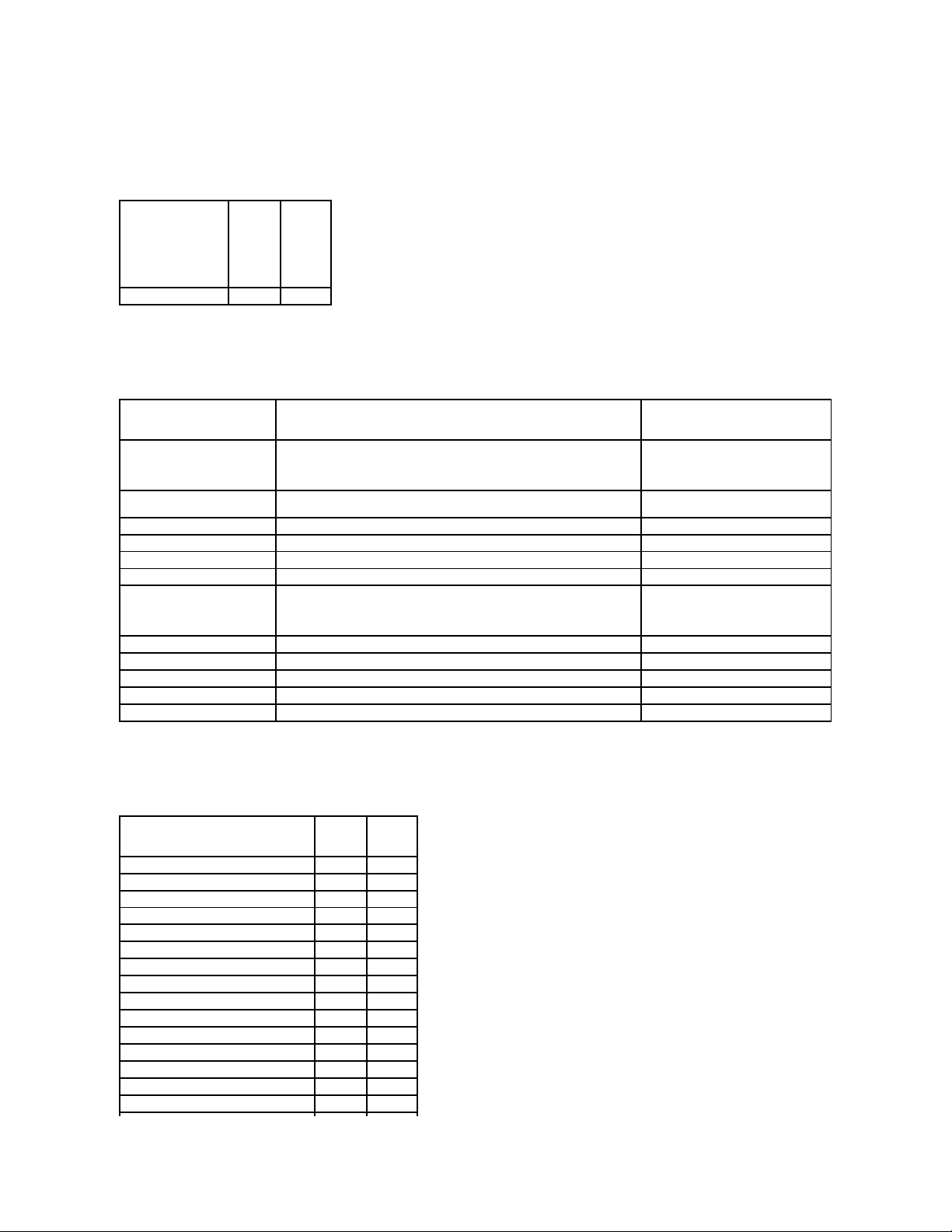
Enclosure and Backplane
Tasks
SCSI
Backplane
SAS
Backplane
PowerVault™20xSand
21xS Enclosures
PowerVault 220S and
221S Enclosures
PowerVault MD1000
Storage Enclosure
PowerVault
MD1120
Enable Alarm
No
No
No
Yes
Yes
Yes
Disable Alarm
No
No
No
Yes
Yes
Yes
Set Temperature Probe
No
No
Yes
Yes
Yes
Yes
Page 21
Enclosure and Backplane Support for Smart Thermal Shutdown
Table A-51.EnclosureSupportforSmartThermalShutdown
Maximum Supported Configuration
Table A-52. Maximum Supported Configuration for SAS and SCSI Controllers
Back to Contents Page
Values
Set Asset Data (includes
asset tag and asset name)
No
No
Yes
Yes
Yes
Yes
Blink Enclosure
No
No
No
No
Yes
Yes
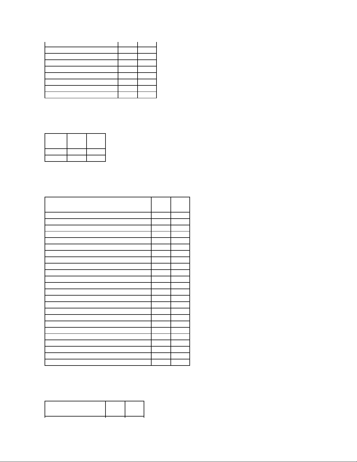
Smart Thermal
Shutdown
SCSI
Backplane
SAS
Backplane
PowerVault 20xS and
21xS Enclosures
PowerVault 220S and
221S Enclosures
PowerVault MD1000
Storage Enclosure
PowerVault
MD1120
Smart Thermal
Shutdown
No
No
No
Yes
No
No
Maximum Supported Configuration
SAS SCSI
External controllers on each Server (a)
2 2 External connectors on each controller (b)
2 2 Enclosures per connector (c)
3
1
Total numbers of enclosures on a server
(a x b x c)
12
4
Page 22
Back to Contents Page
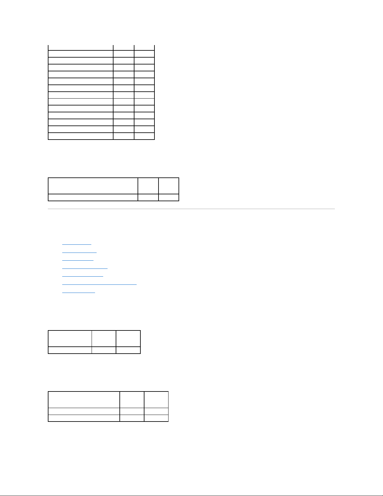
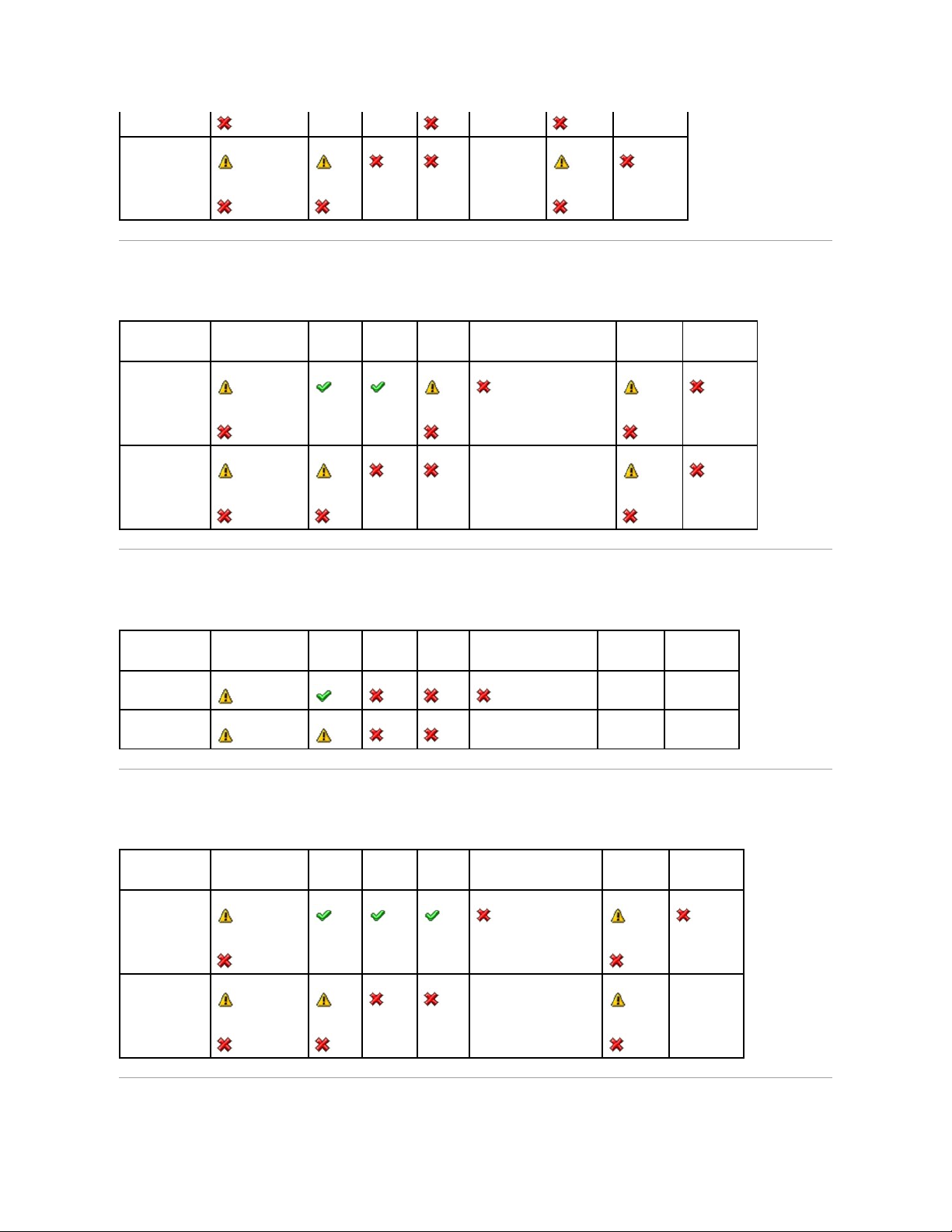
Determining the Health Status for Storage Components
Dell™OpenManage™ServerAdministratorStorageManagementUser'sGuide
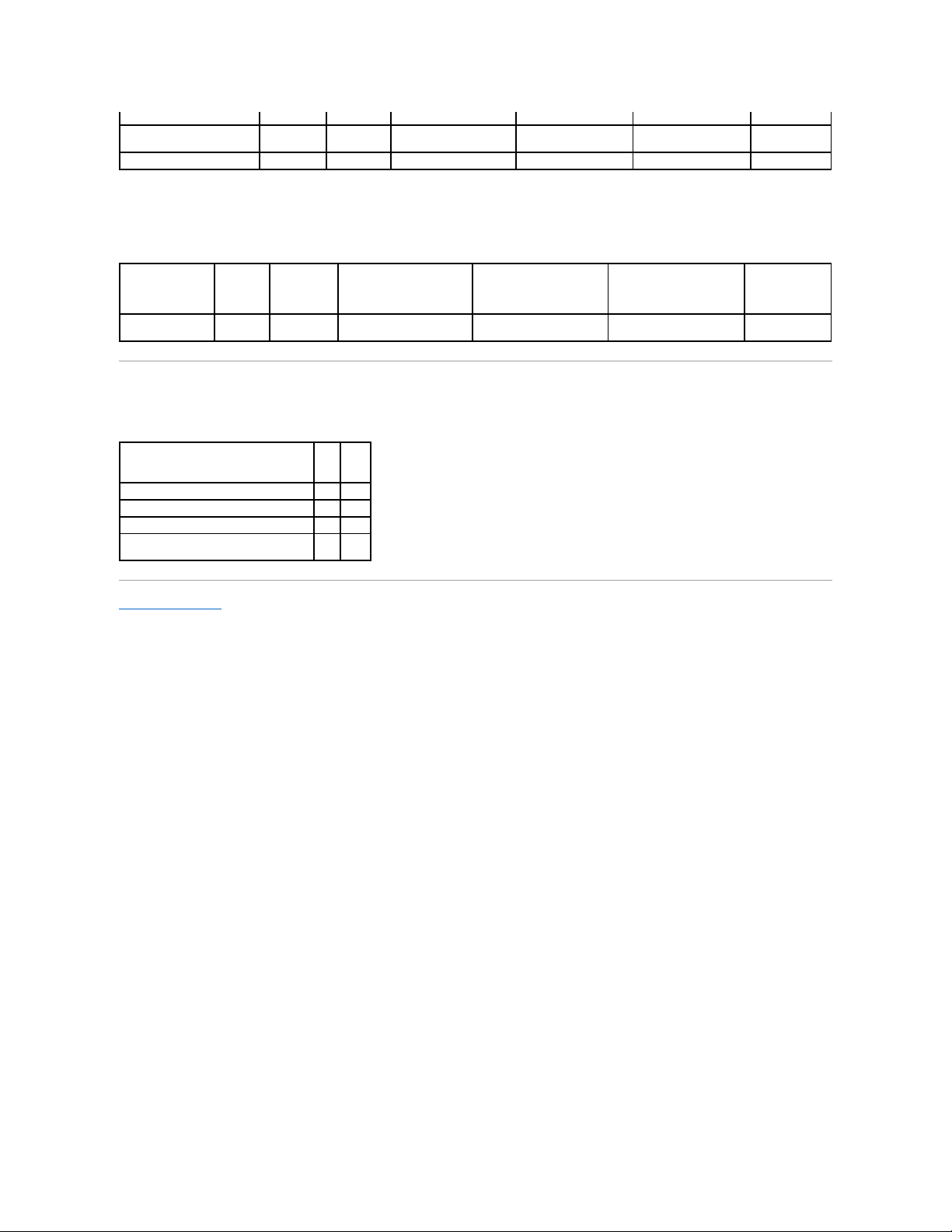
The tables in this appendix indicate how the status of lower-level storage components is "rolled up" into the combined status displayed for the controller or
other higher-level component. The examples provided by these tables do not cover all scenarios, but they do indicate how status is rolled up when a particular
component is in a healthy, degraded, or failed state.
Health Status Rollup: Battery is Charging or Dead
Table B-1. Health Status Rollup: Battery is Charging or Dead (Enclosures Not Included)
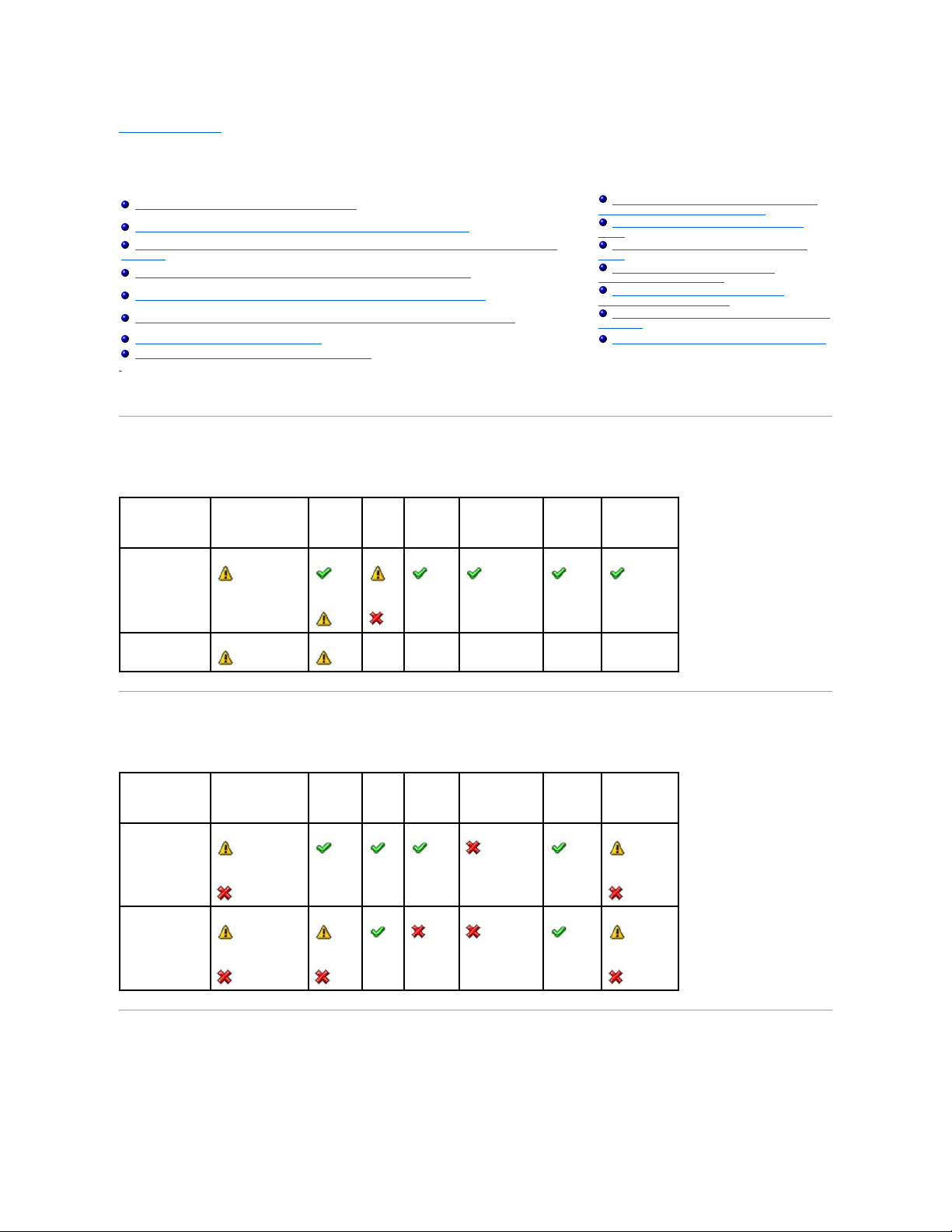
Health Status Rollup: Physical Disks in a Virtual Disk are Failed or Removed
Table B-2. Health Status Rollup: Physical Disks in a Virtual Disk are Failed or Removed (Enclosures Not Included)
Health Status Rollup: Physical Disks in a Virtual Disk are Unsupported, Partially or
Permanently Degraded
Table B-3. Health Status Rollup: Physical Disks in a Virtual Disk are Unsupported, Partially or Permanently Degraded (Enclosures Not
Included)
Health Status Rollup: Battery is Charging or Dead
Health Status Rollup: Enclosure Power Supply
Failed or Power Connection Removed
Health Status Rollup: Physical Disks in a Virtual Disk are Failed or Removed
Health Status Rollup: One Enclosure Fan is
Failed
Health Status Rollup: Physical Disks in a Virtual Disk are Unsupported, Partially or Permanently
Degraded
Health Status Rollup: One Enclosure EMM is
Failed
Health Status Rollup: All Physical Disks in a Virtual Disk are in Foreign State
Health Status Rollup: One Enclosure
Temperature Probe is Failed
Health Status Rollup: Some Physical Disks in a Virtual Disk are in Foreign State
Health Status Rollup: Lost Both Power
Connections to the Enclosure
Health Status Rollup: Virtual Disk is Degraded; Physical Disks are Failed or Rebuilding
Health Status Rollup: One or More Physical Disks
are Failed
Health Status Rollup: Virtual Disk is Failed
Health Status Rollup: Physical Disk is Rebuilding
Health Status Rollup: Unsupported Firmware Version
Storage Subsystem
Controller
Battery
Connector
Physical Disk(s)
Firmware/
Driver
Virtual Disk(s)
Component Status
Health Rollup
NA
NA
NA
NA
NA
Storage Subsystem
Controller
Battery
Connector
Physical Disk(s)
Firmware/
Driver
Virtual Disk(s)
Component Status
Health Rollup
Page 23
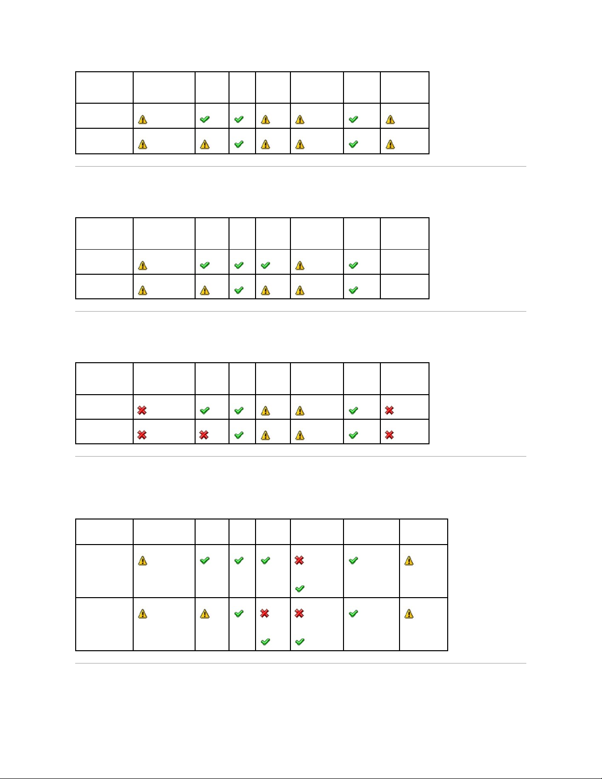
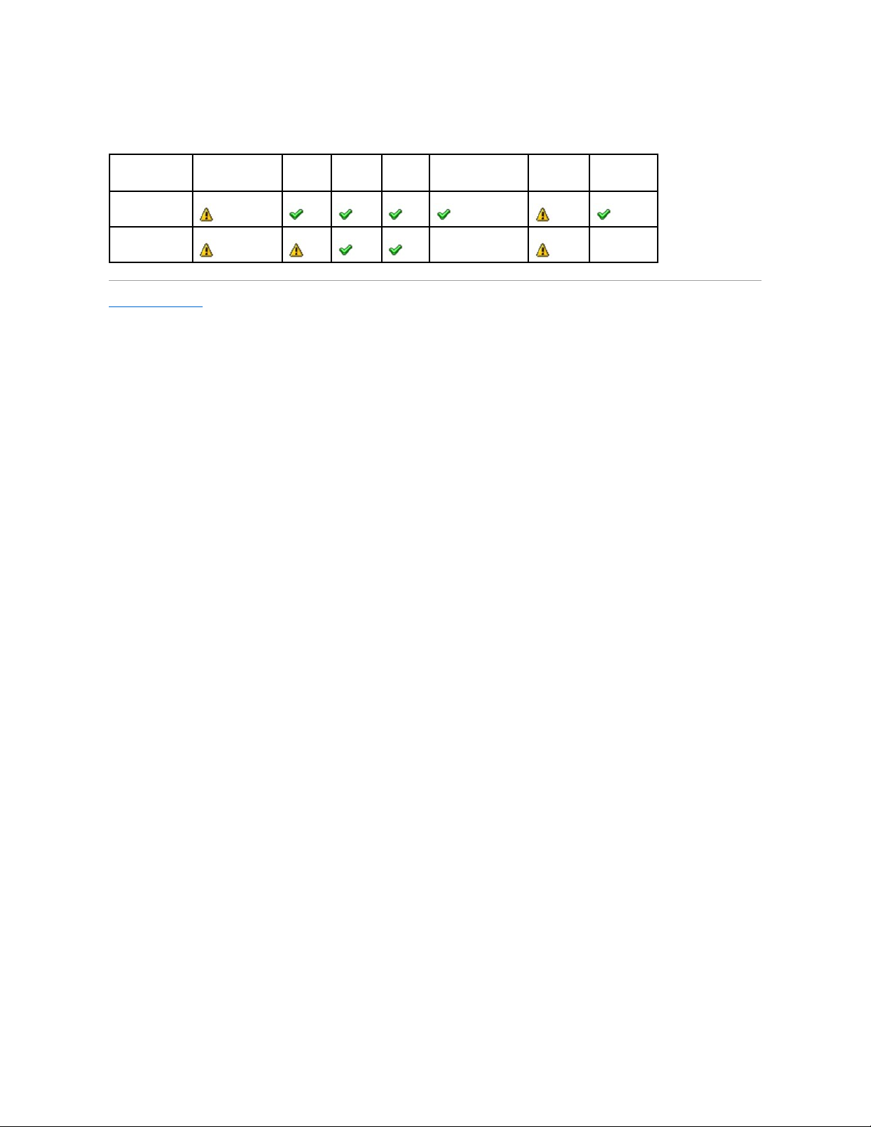
Health Status Rollup: All Physical Disks in a Virtual Disk are in Foreign State
Table B-4. Health Status Rollup: All Physical Disks in a Virtual Disk are in Foreign State (Enclosures Not Included)
Health Status Rollup: Some Physical Disks in a Virtual Disk are in Foreign State
Table B-5. Health Status Rollup: Some Physical Disks in a Virtual Disk are in Foreign State (Enclosures Not Included)
Health Status Rollup: Virtual Disk is Degraded; Physical Disks are Failed or
Rebuilding
Table B-6. Health Status Rollup: Virtual Disk is Degraded; Physical Disks are Failed or Rebuilding (Enclosures Not Included)
Health Status Rollup: Virtual Disk is Failed
Table B-7. Health Status Rollup: Virtual Disk is Failed (Enclosures Not Included)
Storage Subsystem
Controller
Battery
Connector
Physical Disk(s)
Firmware/
Driver
Virtual Disk(s)
Component Status
Health
Rollup
Storage Subsystem
Controller
Battery
Connector
Physical Disk(s)
Firmware/
Driver
Virtual Disk(s)
Component Status
NA
Health Rollup
NA
Storage Subsystem
Controller
Battery
Connector
Physical Disk(s)
Firmware/
Driver
Virtual Disk(s)
Component Status
Health Rollup
Storage Subsystem
Controller
Battery
Connector
Physical Disk(s)
Firmware/Driver
Virtual Disk(s)
Component Status
Health Rollup
Page 24
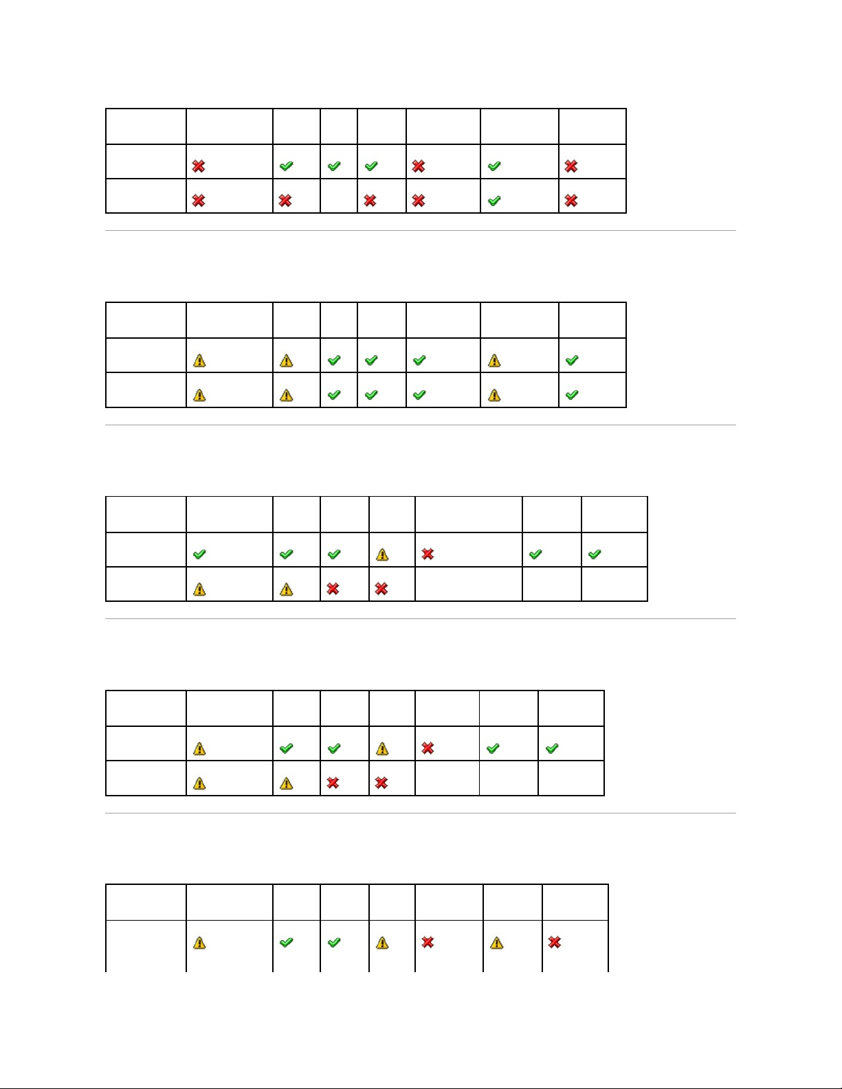
Health Status Rollup: Unsupported Firmware Version
Table B-8. Health Status Rollup: Unsupported Firmware Version (Enclosures Not Included)
Health Status Rollup: Enclosure Power Supply Failed or Power Connection Removed
Table B-9. Health Status Rollup: Enclosure Power Supply Failed or Power Connection Removed
Health Status Rollup: One Enclosure Fan is Failed
Table B-10. Health Status Rollup: One Enclosure Fan is Failed
Health Status Rollup: One Enclosure EMM is Failed
Table B-11. Health Status Rollup: One Enclosure EMM is Failed
Storage Subsystem
Controller
Battery
Connector
Physical Disk(s)
Firmware/Driver
Virtual Disk(s)
Component Status
Health Rollup
Storage Subsystem
Controller
Battery
Connector
Physical Disk(s)
Firmware/Driver
Virtual Disk(s)
Component Status
Health Rollup
Storage Subsystem
Controller
Connector
Enclosure
Enclosure Power Supply
Virtual Disks
Physical Disks
Component Status
Health Rollup
NA
NA
NA
Storage Subsystem
Controller
Connector
Enclosure
Enclosure Fan
Virtual Disks
Physical Disks
Component Status
Health Rollup
NA
NA
NA
Storage Subsystem
Controller
Connector
Enclosure
Enclosure EMM
Virtual Disks
Physical Disks
Component Status
Page 25
Health Status Rollup: One Enclosure Temperature Probe is Failed
Table B-12. Health Status Rollup: One Enclosure Temperature Probe is Failed
Health Status Rollup: Lost Both Power Connections to the Enclosure
Table B-13. Health Status Rollup: Lost Both Power Connections to the Enclosure
Health Status Rollup: One or More Physical Disks are Failed
Table B-14. Health Status Rollup: One or More Physical Disks are Failed
Health Rollup
NA
Storage Subsystem
Controller
Connector
Enclosure
Enclosure Temperature Probe
Virtual Disks
Physical Disks
Component Status
Health Rollup
NA
Storage Subsystem
Controller
Connector
Enclosure
All Enclosure Components
Virtual Disks
Physical Disks
Component Status
NA
NA
Health Rollup
NA
NA
NA
Storage Subsystem
Controller
Connector
Enclosure
Enclosure Physical Disk(s)
Virtual Disks
Physical Disks
Component Status
Health Rollup
NA
NA
Page 26
Health Status Rollup: Physical Disk is Rebuilding
Table B-15. Health Status Rollup: Physical Disk is Rebuilding
Back to Contents Page
Storage Subsystem
Controller
Connector
Enclosure
Enclosure Component
Virtual Disks
Physical Disks
Component Status
Health Rollup
NA
NA
Page 27

Back to Contents Page
Physical Disks
Dell™OpenManage™ServerAdministratorStorageManagementUser'sGuide
Physical disks reside within an enclosure or are attached to the controller. On a RAID controller, physical disks are used to create virtual disks.
Add a New Disk to Your System
1. Install or attach the new physical disk (or disks). Refer to the documentation that came with the disk for more information.
2. Do one of the following depending on the controller technology. See "RAID Controller Technology: SCSI, SATA, ATA, and SAS" for more information.
For SCSI, SATA, and ATA Controllers
a. Select the controller to which the disk is attached and click the Information/Configuration tab.
b. Execute the Rescan task.
The new disk should be displayed in the tree view after the rescan. If the new disk is not displayed, restart the computer.
For SAS Controllers
a. Check the Alert Log for an alert verifying that the system has identified the new disk. You may receive alert "2052" or "2294."
b. Refresh the display by clicking Refresh or by changing screens.
The new physical disk should be displayed in the tree view after refreshing the display. If the new disk is not displayed, restart the computer.
Related Information
l See "Replacing a Failed Disk" if you are replacing a disk that is part of a virtual disk.
l See "Virtual Disk Considerations for PERC 3/SC, 3/DC, 3/QC, 4/SC, 4/DC, 4e/DC, 4/Di, 4e/Si, 4e/Di, CERC ATA100/4ch, PERC 5/E, PERC 5/i, PERC 6/E, and
PERC 6/I Controllers" or "Virtual Disk Considerations for PERC 3/Si, 3/Di, CERC SATA1.5/6ch, and CERC SATA1.5/2s controllers" if you are intending to
include the new disk in a virtual disk.
How to Avoid Removing the Wrong Disk
You can avoid removing the wrong disk by blinking the LED display on the disk that you intend to remove. See the following sections for information on blinking
the LED display:
l See "Blink and Unblink (Physical Disk)" to blink the LED display on a physical disk.
l See "Blink and Unblink (Virtual Disk)" to blink the LED display on all physical disks included in a particular virtual disk.
If you have already removed the wrong disk, see "Recovering from Removing the Wrong Physical Disk."
Replacing a Physical Disk Receiving SMART Alerts
SMART alerts are messages predicting that a disk may fail in the near future. If a physical disk is receiving SMART alerts, you should replace the disk. Use the
following procedures to replace a disk receiving SMART alerts.
Add a New Disk to Your System
Assign and Unassign Global Hot Spare
How to Avoid Removing the Wrong Disk
Online and Offline
Replacing a Physical Disk Receiving SMART Alerts
Clear Physical Disk and Cancel Clear
Other Disk Procedures
Revertible Hot Spare
Physical Disk Properties and Tasks
NOTE: Clicking the Refresh button in the right pane refreshes only the right pane. To view the new physical disk in the left pane tree view, click the
system name displayed at the top of the left pane, or select View --> Refresh from the browser's menu bar.
Page 28

If the disk is part of a redundant virtual disk:
1. Select the redundant virtual disk that includes the physical disk that is receiving SMART alerts and perform the Check Consistency task. See "Check
Consistency" for more information.
2. Select the disk that is receiving SMART alerts and execute the Offline task.
3. Manually remove the disk.
4. Insert a new disk. Make sure that the new disk is the same size or larger as the disk you are replacing. (On some controllers, you may not be able to
use the additional disk space if you insert a larger disk. See "Virtual Disk Considerations for PERC 3/SC, 3/DC, 3/QC, 4/SC, 4/DC, 4e/DC, 4/Di, 4e/Si,
4e/Di, CERC ATA100/4ch, PERC 5/E, PERC 5/i, PERC 6/E, and PERC 6/I Controllers" for more information.) After you complete this procedure, a rebuild is
automatically initiated because the virtual disk is redundant.
If the disk is not part of a redundant virtual disk:
1. Back up data from the virtual disk.
2. Delete the virtual disk.
3. Replace the disk that is receiving SMART alerts.
4. Create a new virtual disk. Make sure that the new virtual disk is the same size or larger than the original virtual disk. For controller-specific information
on creating virtual disks, see "Virtual Disk Considerations for PERC 3/SC, 3/DC, 3/QC, 4/SC, 4/DC, 4e/DC, 4/Di, 4e/Si, 4e/Di, CERC ATA100/4ch, PERC 5/E,
PERC 5/i, PERC 6/E, and PERC 6/I Controllers" and "Virtual Disk Considerations for PERC 3/Si, 3/Di, CERC SATA1.5/6ch, and CERC SATA1.5/2s controllers."
5. Restore the backed up data from the original virtual disk onto the newly created virtual disk.
Related Information:
l "Monitoring Disk Reliability on RAID Controllers"
Other Disk Procedures
See the following sections:
l "Replacing a Failed Disk"
l "Recovering from Removing the Wrong Physical Disk"
l "Moving Physical and Virtual Disks from One System to Another"
l "Troubleshooting"
Physical Disk Properties and Tasks
Use this window to view information about physical disks and execute physical disk tasks.
Physical Disk Properties
The following table describes properties that may be displayed for physical disks depending on the controller.
CAUTION: To avoid potential data loss, you should perform a check consistency before removing a physical disk that is receiving SMART alerts.
The check consistency verifies that all data is accessible within the redundant virtual disk and uses the redundancy to repair any bad blocks that
may be present. In some circumstances, failure to perform a check consistency can result in data loss. This may occur, for example, if the
physical disk receiving SMART alerts has bad disk blocks and you do not perform a check consistency before removing the disk.
Property
Definition
Status
These icons represent the severity or health of the storage component.
Normal/OK
Page 29
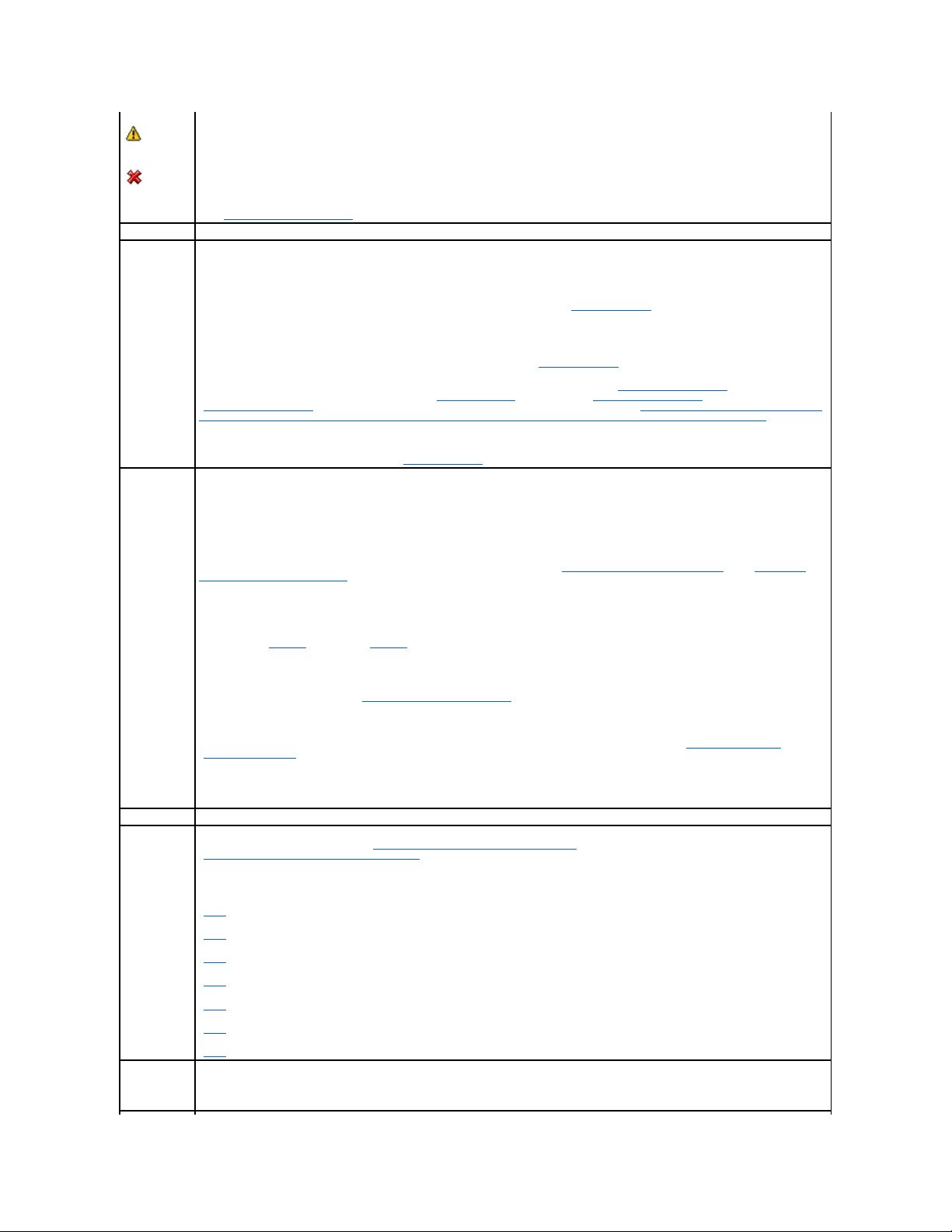
Warning/Non-critical
Critical/Fatal
See "Storage Component Severity" for more information.
Name
This property displays the name of the physical disk. The name is comprised of the connector number followed by the disk number.
State
This property displays the current state of the physical disk.
Ready — The physical disk is functioning normally. If the disk is attached to a RAID controller, Ready state indicates that the disk is available
to be used by a virtual disk. When the physical disk is used in a virtual disk, the state changes to Online.
Online — The physical disk is part of a virtual disk and is functioning normally. See "Online and Offline" for more information.
Degraded — The physical disk has encountered a failure and is operating in a degraded state.
Failed — The physical disk has encountered a failure and is no longer functioning. This state is also displayed when a physical disk that is
part of a redundant virtual disk has been taken offline or deactivated. See "Online and Offline" for more information.
Offline — The physical disk has failed or contains dead segments. Check to see whether the "Remove Dead Segments" task appears on the
physical disk drop-down menu. If it does, perform a "Rescan Controller" and then do a "Remove Dead Segments" for the physical disk. If the
"Remove Dead Segments" task is not displayed, then the physical disk cannot be recovered. See "Considerations for PERC 3/Si, 3/Di, CERC
SATA1.5/6ch, and CERC SATA1.5/2s Controllers When Physical Disks are Shared by Redundant and Nonredundant Virtual Disks" for related
information.
On the PERC 5/E controller, the Offline state indicates that the disk is included in a virtual disk, but it is not receiving I/O. This may occur
when a user has set the disk to Offline. See "Online and Offline" for more information.
Rebuilding — Data from a redundant virtual disk is currently being rebuilt onto the physical disk.
Incompatible — The physical disk is not suitable for a rebuild. The physical disk may be too small or it may be using an incompatible
technology. For example, you cannot rebuild a SAS disk with a SATA disk or a SATA disk with a SAS disk.
Removed — The physical disk has been removed. This state only applies to physical disks that are part of a virtual disk.
Clear — The Clear task is being performed on the physical disk. A physical disk may also display the Clear state if the physical disk is a
member of a virtual disk that is being slow initialized. For more information, see "Clear Physical Disk and Cancel Clear" and "Format and
Initialize; Slow and Fast Initialize."
SMART Alert Detected — A SMART alert (predictive failure) has been detected on the physical disk. The physical disk may fail and should be
replaced. This state applies to physical disks attached to non-RAID controllers.
Unknown — The physical disk has failed or is in an unusable state. In some cases the physical disk can be returned to a usable state by
performing an "Initialize" task. If the "Initialize" task does not appear on the physical disk drop-down menu, then this disk cannot be
recovered.
Foreign — The physical disk has been moved from another controller and contains all or some portion of a virtual disk (foreign
configuration). A physical disk that has lost communication with the controller due to a power loss, faulty cable or other failure event may
also display the Foreign state. See "Foreign Configuration Operations" for more information.
Unsupported — The physical disk is using an unsupported technology. The physical disk cannot be managed by Storage Management.
Replacing — A Replace Member Disk task is being performed on the physical disk. For more information, see "Replace Member Disk" and
"Revertible Hot Spare."
NOTE: You can cancel the copying of data at any time during the execution of this task.
Capacity
This property displays the full capacity of the disk.
Failure
Predicted
This property displays whether or not the physical disk has received a SMART alert and is therefore predicted to fail. For more information on
SMART predictive failure analysis, see "Monitoring Disk Reliability on RAID Controllers." For information on replacing the physical disk, see
"Replacing a Physical Disk Receiving SMART Alerts."
You may also want to review the Alert Log to see whether the physical disk has generated alerts pertaining to a SMART predictive failure.
These alerts can assist you in identifying the cause of the SMART alert. The following alerts may be generated in response to a SMART alert:
"2094"
"2106"
"2107"
"2108"
"2109"
"2110"
"2111"
Progress
This property displays how close to completion an operation is that is being performed on the physical disk. For example, if the physical disk
is being rebuilt, then a value of 52% indicates that the rebuild is 52% complete.
This property is only displayed when an operation is being performed on the physical disk.
Page 30
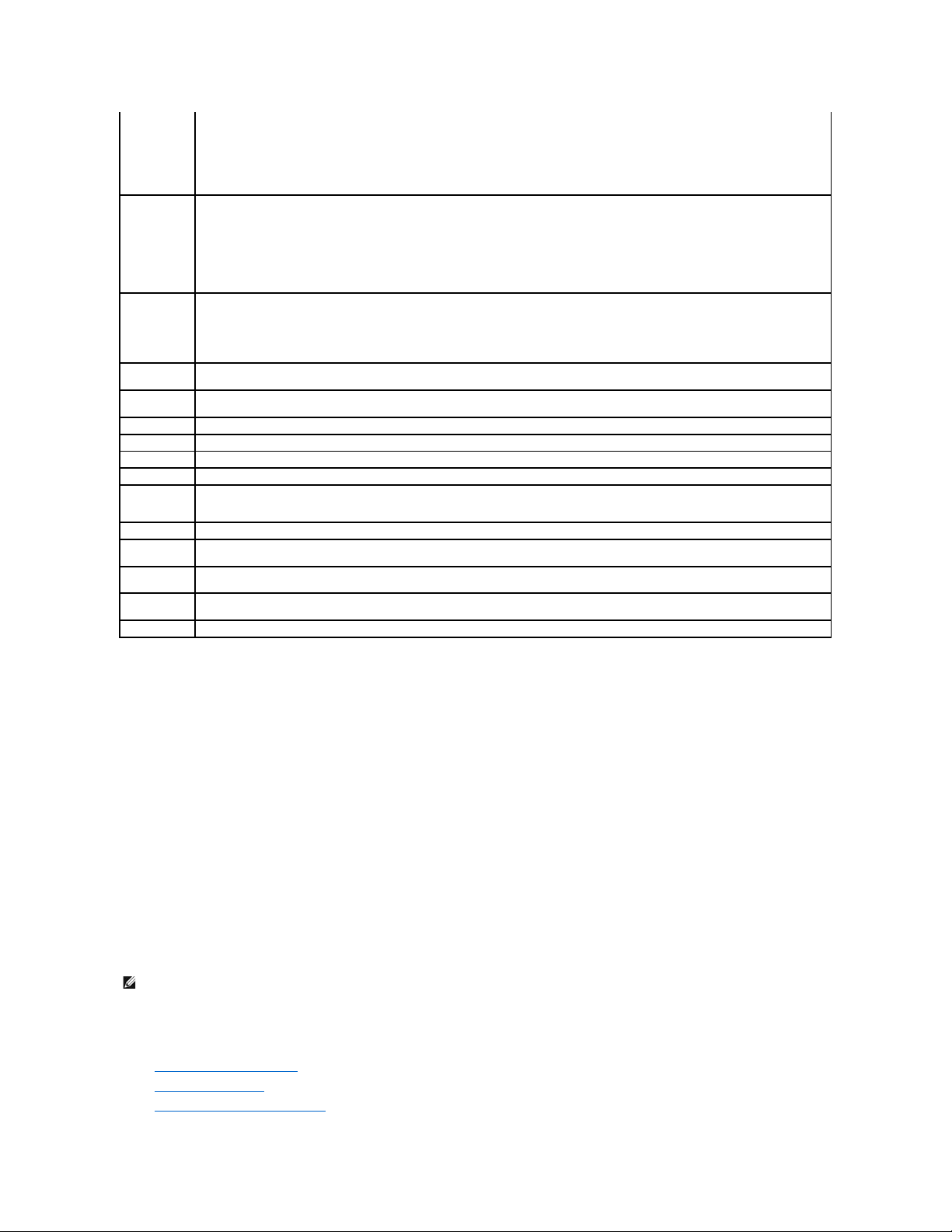
Physical Disk Tasks
Do the following to execute a physical disk task:
1. Expand the Storage tree object to display the controller objects.
2. Expand a controller object.
3. Expand a Connector object.
4. Expand the enclosure or Backplane object.
5. Select the Physical Disks object.
6. Select the Information/Configuration subtab.
7. Select a task from the Available Tasks drop-down menu.
8. Click Execute.
Physical Disk Drop-down Menu Tasks:
l "Blink and Unblink (Physical Disk)"
l "Remove Dead Segments"
l "Assign and Unassign Global Hot Spare"
Bus Protocol
This property displays the technology that the physical disk is using. Possible values are:
SCSI — Small Computer System Interface
SAS — Serial Attached SCSI
SATA — Serial Advanced Technology Attachment (SATA)
Media
This property displays the media type of the physical disk. The possible values are:
HDD—Hard Disk Drive. A HDD is a non-volatile storage device which stores digitally-encoded data on rapidly rotating platters with magnetic
surfaces.
SSD—Solid State Drive. An SSD is a data storage device that uses solid-state memory to store persistent data.
Unknown—Storage Management is unable to determine the media type of the physical disk.
Used RAID Disk
Space
This property displays how much of the physical disk space is being used by the virtual disks on the controller. This property is Not
Applicable for physical disks attached to non-RAID controllers.
In certain circumstances, the Used RAID Disk Space displays a value of zero (0) even though a portion of the physical disk is being used.
This occurs when the used space is 0.005 GB or less. The algorithm for calculating the used disk space rounds a figure of 0.005 GB or less to
0. Used disk space that is between 0.006 GB and 0.009 GB is rounded up to 0.01 GB.
Available RAID
Disk Space
This property displays the amount of available space on the disk. This property is Not Applicable for physical disks attached to non-RAID
controllers.
Hot Spare
This property indicates whether the disk has been assigned as a hot spare. This property is Not Applicable for physical disks attached to
non-RAID controllers.
Vendor ID
This property displays the disk's hardware vendor.
Product ID
This property displays the disk's product ID.
Revision
This property displays the disk's revision number.
Serial No.
This property displays the disk's serial number.
Negotiated
Speed
This property displays the speed of data transfer that the disk negotiated while spinning up and upon initial communication with the
controller. This speed is dependent on the speed of the disk, the capable speed of the controller, the current speed of the controller on that
connector, and the speed of the EMM (Enclosure Management Module) on the enclosure.
Capable Speed
This property displays the highest possible speed that the device can transfer data.
Manufacture
Day
This property displays the day of the month during which the physical disk was manufactured.
Manufacture
Week
This property displays the week of the year during which the physical disk was manufactured.
Manufacture
Year
This property displays the year that the physical disk was manufactured.
SAS Address
This property displays the SAS address of the physical disk. The SAS address is unique to each SAS disk.
NOTE: Different controllers support different features. For this reason, the tasks displayed on the Tasks drop-down menu can vary depending on which
controller is selected in the tree view. If no tasks can be performed because of controller or system configuration limitations, then the Tasks drop-down
menu displays No Task Available.
Page 31

l "Prepare to Remove"
l "Online and Offline"
l "Initialize"
l "Rebuild"
l "Cancel Rebuild"
l "Clear Physical Disk and Cancel Clear"
l "Revertible Hot Spare"
Blink and Unblink (Physical Disk)
Does my controller support this feature? See "Supported Features."
The Blink task allows you to find a disk within an enclosure by blinking one of the light-emitting diodes (LEDs) on the disk. You may want to use this task to
locate a failed disk.
On most controllers, the Blink task automatically cancels after a short duration such as 30 or 60 seconds. If you need to cancel the Blink task or if the physical
disk continues to blink indefinitely, use the Unblink task.
Remove Dead Segments
Does my controller support this feature? See "Supported Features."
The Remove Dead Segments task recovers disk space that is currently unusable. A dead or orphaned disk segment refers to an area of a physical disk that is
unusable for any of the following reasons:
l The dead segment is an area of the physical disk that is damaged.
l The dead segment is included in a virtual disk, but the virtual disk is no longer using this area of the physical disk.
l The physical disk contains more than one virtual disk. In this case, disk space that is not included in one of the virtual disks may be unusable.
l The dead segment resides on a physical disk that has been disconnected from and then reconnected to the controller.
Prepare to Remove
Does my controller support this feature? See "Supported Features."
Use the Prepare to Remove task to spin down a physical disk so that it can safely be removed from an enclosure or backplane. It is recommended that you
perform this task before removing a disk to prevent data loss.
This task causes the lights on the disk to blink. You can safely remove the disk under the following conditions:
l Wait for about 30 seconds to allow the disk to spin down.
l Wait until you notice the initial blink pattern has changed into a different pattern or the lights have stopped blinking.
A physical disk is no longer in Ready state after doing a Prepare to Remove. Removing the physical disk from the enclosure or backplane and replacing it
causes the physical disk to spin up and return to Ready state.
In some cases, a rescan is required for the controller to recognize configuration changes such as the removal of a disk. See "Rescan to Update Storage
Configuration Changes" for more information.
Initialize
Does my controller support this feature? See "Supported Features."
NOTE: The Blink and Unblink tasks are only supported for hotswap physical disks (disks that reside in a carrier). When using an Ultra SCSI, Ultra2 SCSI,
Ultra160 SCSI, LSI 1020, LSI 1030, or LSI PCI-e U320 controller, the Blink and Unblink tasks apply to physical disks contained in carriers that can be
inserted into a server or an enclosure. If the physical disk is not contained in a carrier but is instead designed to be connected with a SCSI cable
(typically a ribbon cable), then the Blink and Unblink tasks are disabled.
NOTE: This procedure is not available for physical disks that have been assigned as a hot spare or physical disks that are part of a virtual disk. In
addition, this procedure is only supported for hotswap physical disks (disks that reside in a carrier).
NOTE: This procedure is not supported on the CERC ATA100/4ch, CERC SATA1.5/6ch, and CERC SATA1.5/2s controllers. For the PERC 4/IM controller, this
procedureisonlysupportedonaPowerEdge™1855system.
Page 32

The Initialize task prepares a physical disk for use as a member of a virtual disk.
Physical disks attached to PERC 3/Si, 3/Di, and CERC SATA1.5/6ch controllers must be initialized before they can be used. On these controllers, the Initialize
task can only be performed once on a physical disk. In some cases a physical disk that is in an Unknown state can be returned to a usable state by performing
the Initialize task. The Initialize task is not displayed for physical disks that have already been initialized using Storage Management or the BIOS.
Rebuild
Does my controller support this feature? See "Supported Features."
Use the Rebuild task to reconstruct data when a physical disk in a redundant virtual disk fails. See "Replacing a Failed Disk that is Part of a Redundant Virtual
Disk" for more information.
Rebuilding a disk may take several hours.
Cancel Rebuild
Does my controller support this feature? See "Supported Features."
Use the Cancel Rebuild task to cancel a rebuild that is in progress. If you cancel a rebuild, the virtual disk remains in a degraded state. The failure of an
additional physical disk can cause the virtual disk to fail and may result in data loss. It is highly recommended that you rebuild the failed physical disk as soon
as possible.
Assign and Unassign Global Hot Spare
Does my controller support this feature? See "Supported Features."
A global hot spare is an unused backup disk that is part of the disk group. Hot spares remain in standby mode. When a physical disk that is used in a virtual
disk fails, the assigned hot spare is activated to replace the failed physical disk without interrupting the system or requiring your intervention. When a hot
spare is activated, it rebuilds the data for all redundant virtual disks that were using the failed physical disk.
You can change the hot spare assignment by unassigning a disk and choosing another disk as needed. You can also assign more than one physical disk as a
global hot spare.
Global hot spares must be assigned and unassigned manually. They are not assigned to specific virtual disks. If you want to assign a hot spare to a virtual
disk (it will replace any physical disk that fails in the virtual disk) then use the "Assign and Unassign Dedicated Hot Spare."
You should be familiar with the size requirements and other considerations associated with hot spares. See the following sections for more information:
l "Protecting Your Virtual Disk with a Hot Spare"
l "Considerations for Hot Spares on PERC 3/SC, 3/DC, 3/QC, 4/SC, 4/DC, 4e/DC, 4/Di, 4e/Si, 4e/Di, CERC ATA100/4ch, PERC 5/E, PERC 5/i, PERC 6/E, PERC
6/I, and CERC 6/I Controllers"
l "Considerations for Hot Spares on PERC 3/Si, 3/Di, CERC SATA1.5/6ch, S100, and S300 Controllers"
l "Global Hot Spare Considerations on a SAS 6/iR"
Online and Offline
CAUTION: This is a data-destructive task. Any virtual disks residing on this physical disk will be removed.
NOTE: If you cancel the rebuild of a physical disk that is assigned as a hot spare, you will need to reinitiate the rebuild on the same physical disk in
order to restore the data. Canceling the rebuild of a physical disk and then assigning another physical disk as a hot spare will not cause the newly
assigned hot spare to rebuild the data. You will need to reinitiate the rebuild on the physical disk that was the original hot spare.
NOTE: On SAS 6/iR controllers, you cannot assign physical disks that have boot partitions, as hot spares.
NOTE: On PERC S100 and S300 controllers, if there is free space available on the global hot spare, it continues to function as a spare even after
replacing a failed physical disk. See "Considerations for Hot Spares on PERC 3/Si, 3/Di, CERC SATA1.5/6ch, S100, and S300 Controllers".
NOTE: When deleting virtual disks, all assigned global hot spares may be automatically unassigned when the last virtual disk associated with the
controller is deleted.
CAUTION: The SAS 6/iR controller enables you to assign two physical disks as global hot spare. Assigning a physical disk as a global hot spare on
a SAS 6/iR controller is likely to cause data loss from the physical disk. If the system or boot partition resides on the physical disks, it may be
destroyed. You should only assign physical disks that do not contain critical data. For more information about global hot spares and the SAS 6/iR,
see "Global Hot Spare Considerations on a SAS 6/iR."
Page 33

Does my controller support this feature? See "Supported Features."
The Online and Offline tasks only apply to physical disks that are included in a redundant virtual disk and attached to a PERC 3/SC, 3/DC, 3/QC,4/SC, 4/DC,
4e/Si, 4e/Di, 4e/DC, 4/Di, or CERC ATA100/4ch controller.
Use the Offline task to deactivate a disk before removing it. Use the Online task to reactivate an offline disk. In some cases, you may want to use the Online
task on a failed disk in an attempt to recover data from the disk. See "Using the Physical Disk Online Command on Select Controllers" for more information.
To online or offline the physical disk:
1. Review the physical disk that will be made online or offline. When making a physical disk offline, be aware that there can be data loss. Back up your
data, if necessary. If you want to blink the physical disk, click the Blink button.
2. Click Online or Offline when ready or click Go Back to Previous Page.
To locate this task in Storage Management:
1. Expand the Storage tree object to display the controller objects.
2. Expand a controller object.
3. Expand a Connector object.
4. Expand the enclosure or Backplane object.
5. Select the Physical Disks object.
6. Select Online or Offline from the Available Tasks drop-down menu of the physical disk you want to make online or offline.
7. Click Execute.
Clear Physical Disk and Cancel Clear
Does my controller support this feature? See "Supported Features."
Use the clear physical disk task to erase data residing on a physical disk. The Clear task applies to physical disks that are in Ready state and that contain data
or that are in Clear state.
To clear the physical disk:
1. Review the physical disk that will be erased by the clear task. Be sure that it does not contain necessary data and make a backup if necessary. If you
want to blink the physical disk, click the Blink button.
2. Click Clear when you are ready to erase all information on the physical disk. To exit without clearing the physical disk, click Go Back to Previous Page.
To locate this task in Storage Management:
1. Expand the Storage tree object to display the controller objects.
2. Expand a controller object.
3. Expand a Connector object.
4. Expand the enclosure or Backplane object.
NOTE: The Online and Offline tasks are not supported on the PERC 4/IM controller or the PERC 3/Si, 3/Di, CERC SATA1.5/6ch, and CERC SATA1.5/2s
controllers.
NOTE: A physical disk may display the Clear state if it is a member of a virtual disk that is being slow initialized. Performing a Cancel Clear task on the
physical disk causes the Slow Initialize task to be cancelled for the entire virtual disk. See "Format and Initialize; Slow and Fast Initialize" and
"Considerations for Slow Initialize" for more information.
Page 34

5. Select the Physical Disks object.
6. Select Clear from the Available Tasks drop-down menu of the physical disk you want to clear.
7. Click Execute.
Revertible Hot Spare
Does my controller support this feature? See "Supported Features."
Use the Revertible Hot Spare task to copy data back from a hot spare to a physical disk.
If the physical disk in a virtual disk fails, the data on the failed disk is copied to the assigned hot spare. If you replace the failed disk with a new physical disk
and if you have enabled the revertible hot spare task, the data is copied from the erstwhile hot spare to the new disk.
You can also use the Revertible Hot Spare task to copy data from a physical disk to the hot spare on a predictive failure event.
If Revertible Hot Spare is enabled and the physical disk is SMART-enabled, the controller firmware automatically starts copying data from the SMART-enabled
disk in the virtual disk to the hot spare.
To enable Revertible Hot Spare:
1. On the Change Controller Properties page, enable Revertible Hot Spare and Auto replace on predictive failure.
2. Click Apply Changes.
To locate this task in Storage Management:
1. Expand the Storage tree object to display the controller objects.
2. Select a controller object on which you want to enable the revertible hot spare task and select the Information/Configuration tab.
3. From the Controller Task drop down menu, select Change Controller Properties and click Execute.
Back to Contents Page
NOTE: To use the Revertible Hot Spare task, you should have assigned a hot spare to the virtual disk.
NOTE: If the disk is not SMART-enabled or if the Auto Replace on Predictive Failure option is disabled, the failed disk will not be replaced automatically.
NOTE: The Rebuild rate for Revertible Hot Spare will be the same as defined for the controller.
Page 35

Back to Contents Page
RAID Controller Batteries
Dell™OpenManage™ServerAdministratorStorageManagementUser'sGuide
Battery Properties and Tasks
Some RAID controllers have batteries. If the controller has a battery, Storage Management displays the battery under the controller object in the tree view.
In the event of a power outage, the controller battery preserves data that is in the nonvolatile cache memory (NVRAM) but not yet written to disk. The battery
is designed to provide a minimum of 72 hours protection for DIMMs up to 64 MB and 48 hours protection for 128-MB DIMMs. The actual period of protection (or
holdover time) depends on the battery's charge level.
When a RAID controller is first installed in a server, the battery is fully discharged. When the server is powered, the battery begins a full charge cycle. On most
controllers, it takes three hours to fully charge the battery. The controller can be used during this time; however, the battery is unable to meet the specified
holdover time until it is fully charged. The battery is still able to handle brief power losses during the initial charge cycle.
There are two types of controller batteries:
l NiMHi batteries
l Li-Ion batteries
The NiMHi batteries need to be reconditioned approximately every six months to maintain reliability. (See "Recondition Battery" for more information.) A battery
recondition fully discharges and then recharges the battery. When the battery needs reconditioning, the controller reports its state as Degraded. In addition,
the controller may generate event "2145" to indicate that the battery needs reconditioning.
The Li-Ion or lithium ion batteries are automatically reconditioned by the controller. These batteries do not require that you run the battery recondition task. To
see which type of battery the RAID controller has, refer to the documentation that came with the controller.
All RAID controller batteries should be replaced every three years. You should also monitor the Recharge Count and Max Recharge Count properties for the
battery. (See "Battery Properties" for more information.) These properties indicate when the battery is approaching the maximum number of times that it can
be recharged. When the battery approaches this limit, it should be replaced.
Related Information:
l "Battery Properties and Tasks"
l "Recondition Battery"
l "Start Learn Cycle"
l "Battery Delay Learn Cycle"
Battery Properties and Tasks
Use this window to view information about the battery and execute battery tasks.
Battery Properties
The battery tree-view object has the following properties.
NOTE: Some controllers do not have batteries. Other controllers have lithium ion batteries which are automatically reconditioned and therefore do not
have a Recondition task in Storage Management.
Property
Definition
Status
These icons represent the severity or health of the storage component.
Normal/OK
Warning/Non-critical
Critical/Fatal
See "Storage Component Severity" for more information.
Name
This property displays the name of the battery.
State
This property displays the current status of the battery. Possible values are:
Ready — The battery is functioning normally.
Page 36

Battery Tasks
Do the following to execute a drop-down menu battery task:
1. Expand the Storage tree object to display the controller objects.
2. Expand a controller object.
3. Select the Battery object.
4. Select a task from the Available Tasks drop-down menu.
5. Click Execute.
Drop-down Menu Battery Tasks:
l "Recondition Battery"
Degraded — The battery needs to be reconditioned.
Reconditioning — The battery is being reconditioned. See "Recondition Battery" for more information.
Charging — The battery is undergoing the recharge phase of the battery Learn cycle. See "Start Learn Cycle" for more information.
Learning — The battery is undergoing the discharge phase of the battery Learn cycle. See "Start Learn Cycle" for more information.
Missing — The controller is missing a battery.
Power Low — The battery charge is low and the battery needs to be reconditioned.
Failed — The battery has failed and needs to be replaced.
Unknown — The battery state is not available.
Predicted
Capacity
Status
This property displays the charge capacity of the battery. Possible values are:
Ready — The battery can be charged to full capacity.
Failed — The battery cannot be charged and needs to be replaced.
Unknown — The battery is completing a Learn cycle. The charge capacity of the battery cannot be determined until the Learn cycle is
complete.
Learn State
This property displays the current status of the battery Learn cycle. Possible values are:
Active — The Learn cycle is currently in progress.
Failed — The Learn cycle initiated but then terminated without completing successfully.
Timed out — The Learn cycle is timed out.
Requested — The Learn State displays Requested when either the controller firmware or a user attempts to initiate a Learn cycle while the
battery is charging. The battery must be fully charged before the Learn cycle begins. The Learn State displays Requested until the battery is
fully charged. When the battery is fully charged, the Learn cycle will begin.
Idle — The Learn cycle is currently not active.
Due — The Learn cycle is due.
Learn Mode
Auto — Storage Management will perform an automatic learn cycle based on the time you set.
Warn — The Learn cycle is past the default 90 days.
NOTE: Warn is available only on SAS controllers with firmware version 6.1 and later.
When the battery is in Warn mode, the status of the controller is displayed as degraded.
Next Learn
Time
This property displays the number of days and hours left before the controller firmware initiates the next Learn cycle.
Maximum
Learn Delay
This property displays the maximum number of days and hours that you can delay the battery Learn cycle. The controller firmware
automatically initiates the battery Learn cycle. You cannot stop or pause the Learn cycle, but you can delay it. See "Battery Delay Learn
Cycle" and "Start Learn Cycle" for more information.
Recharge
Count
This property displays the number of times the controller's battery has been recharged.
Max Recharge
Count
This property displays the maximum number of times the controller's battery can be recharged.
Page 37

l "Start Learn Cycle"
l "Battery Delay Learn Cycle"
Recondition Battery
Does my controller support this feature? See "Supported Features."
Some controllers have NiMHi batteries which need to be reconditioned approximately every six months to maintain reliability. This reconditioning cycle requires
a full discharge and recharge of the battery. It ensures that the battery's capacity is being measured correctly and that the battery's full holdover time is
maintained. See "RAID Controller Batteries" for more information.
The controller battery should be reconditioned when either of the following occurs:
l The controller reports the battery state as Degraded. See "Battery Properties" for more information on the battery state.
l The controller generates event "2145" indicating that the battery needs reconditioning.
The battery recondition takes approximately 8 to 10 hours. During this time, the battery is fully discharged and recharged. The battery holdover time is
reduced to zero (during discharge) and then restored as the battery is fully charged. The write cache is disabled during the battery recondition resulting in
performance degradation.
Do the following to recondition the controller battery:
1. Expand the Storage tree object to display the controller objects.
2. Expand the controller object.
3. Select the Battery object.
4. Select Recondition Battery from the Available Tasks drop-down menu.
5. Click Execute.
Related information:
l "Battery Properties"
Start Learn Cycle
Does my controller support this feature? See "Supported Features."
Use the Start Learn Cycle task to initiate the battery Learn cycle.
The battery Learn cycle discharges and then fully charges the controller battery.
The Learn cycle recalibrates the battery integrated circuit so that the controller can determine whether the battery can maintain the controller cache for the
prescribed period of time in the event of a power loss. For example, some controller batteries are required to maintain the controller cache for 72 hours.
While the Learn cycle is in progress, the battery may not be able to maintain the cache during a power loss. If the controller is using write-back cache policy,
then the controller changes to write-through cache policy until the Learn cycle completes. The write-through cache policy writes the data directly to the disk
and reduces the risk that data can be lost in the cache if there is a power loss.
The controller firmware automatically initiates the Learn cycle every 90 days. You can, however, delay the start time of the Learn cycle for a further seven
days, after which the firmware automatically initiates the Learn cycle. For more information, see "Battery Delay Learn Cycle."
Battery Delay Learn Cycle
Does my controller support this feature? See "Supported Features."
NOTE: The Recondition Battery task is only available on controllers with NiMHi batteries that are in Degraded state or that have generated alert "2145."
Some controllers do not have batteries. Other controllers have lithium ion batteries which are automatically reconditioned and therefore do not have a
recondition task in Storage Management.
NOTE: If you have set the controller to write-back force cache policy, then the cache policy is not changed during the Learn cycle. When using write-back
force cache policy, it is possible for data loss to occur if there is a power loss while the Learn cycle is in progress.
NOTE: The Learn cycle cannot be performed while the battery is charging. If either a user or the controller firmware initiate the Learn cycle while the
battery is charging, then the battery Learn State displays Requested. When the battery is fully charged, the Learn cycle will begin.
Page 38

The controller firmware automatically initiates the battery Learn cycle every 90 days. Although you cannot stop the firmware from running the Learn cycle, you
can delay the start time of the Learn cycle for up to seven days. See "Start Learn Cycle" for more information on the battery Learn cycle.
To delay the battery Learn cycle:
1. Type a numerical value in the Days text box. The value must be within the 0 – 7 range. The value you enter indicates the number of days for which you
want to delay the battery Learn cycle. The Learn cycle can be delayed for a maximum of seven days.
2. Type a numerical value in the Hours text box. The value must be within the 0 – 23 range. The value you enter indicates the number of hours for which
you want to delay the battery Learn cycle.
3. Click Apply Changes. If you want to exit and cancel your changes, click Go Back To Battery Information Page.
To locate this task in Storage Management:
1. Expand the Storage tree object to display the controller objects.
2. Expand the controller object.
3. Select the Battery object.
4. Select Delay Learn Cycle from the Available Tasks drop-down menu.
5. Click Execute.
Related Information:
l "Battery Properties and Tasks"
l "Start Learn Cycle"
Back to Contents Page
Page 39

Back to Contents Page
BIOS Terminology
Dell™OpenManage™ServerAdministratorStorageManagementUser'sGuide
BIOS Terms and the PERC 3/SC, 3/DC, 3/QC, 4/SC, 4/DC, 4e/DC, 4/Di, and CERC ATA100/4ch Controllers
BIOS Terms and the PERC 3/Si, 3/Di, CERC SATA1.5/6ch, and CERC SATA1.5/2s Controllers
The terminology used by Storage Management can be different from the terminology used in the controller BIOS. The following sections show some of these
differences.
BIOS Terms and the PERC 3/SC, 3/DC, 3/QC, 4/SC, 4/DC, 4e/DC, 4/Di, and CERC
ATA100/4ch Controllers
Table 17-1. Naming convention differences between Storage Management and PERC BIOS Configuration Utility
BIOS Terms and the PERC 3/Si, 3/Di, CERC SATA1.5/6ch, and CERC SATA1.5/2s
Controllers
Table 17-2.NamingconventiondifferencesbetweenStorageManagementandPERCBIOSContainerConfigurationUtility(CCU)
Back to Contents Page
Storage Management
PERC BIOS Configuration Utility for the 3/SC, 3/DC, 3/QC, 4/SC, 4/DC, 4e/DC, 4/Di, and CERC ATA100/4ch Controllers
Controller
Adapter
Virtual Disk
Logical Drive
Physical disk
Physical Drive
Reconfigure Virtual Disk
Reconstruct
Storage Management
PERC BIOS CCU for the 3/Si, 3/Di, CERC SATA1.5/6ch, and CERC SATA1.5/2s Controllers
Virtual Disk
Container
Physical disk
Drive
Check Consistency
Scrub
Stripe Size
Chunk Size
Concatenation
Volume
Concatenation of RAID 1
Volume
RAID 0
RAID-0 (Stripe)
RAID 1
RAID-1 (Mirror)
Diagnostics
Verify
Page 40

Back to Contents Page
Connectors
Dell™OpenManage™ServerAdministratorStorageManagementUser'sGuide
Channel Redundancy and Thermal Shutdown
Channel Redundancy on PERC 3/DC, 3/QC, 4/DC, 4e/DC, 4/Di, and 4e/Di Controllers
Creating a Channel-redundant Virtual Disk
Connector Health
Connector Properties and Tasks
Logical Connector Properties and Tasks
A controller contains one or more connectors (channels or ports) to which you can attach disks. A connector is externally accessible for attaching an enclosure
(with external disks) to the system. A connector may also be attached to the system's backplane (for internal disks). The controller's connectors are displayed
by expanding the controller object in the tree view.
Channel Redundancy and Thermal Shutdown
It is possible to create a virtual disk that uses physical disks that are attached to different controller channels. The physical disks may reside in an external
enclosure or the backplane (internal enclosure). If the virtual disk is maintaining redundant data on different channels, then the virtual disk is channel
redundant. Channel redundancy means that if one of the channels fails, data will not be lost because redundant data resides on another channel.
Channel redundancy might also be used for disks that reside in enclosures subject to thermal shutdown. Should the enclosure attached to one of the channels
shut down, redundant data is maintained on the other channel.
Channel redundancy is implemented by selecting physical disks on different channels when using the Create Virtual Disk Advanced Wizard.
Related Information:
l "SMART Thermal Shutdown"
l "Channel Redundancy on PERC 3/DC, 3/QC, 4/DC, 4e/DC, 4/Di, and 4e/Di Controllers"
l "Creating a Channel-redundant Virtual Disk"
Channel Redundancy on PERC 3/DC, 3/QC, 4/DC, 4e/DC, 4/Di, and 4e/Di Controllers
The following considerations apply when creating a channel-redundant virtual disk on these controllers:
l It is recommended that you use a RAID 10 or RAID 50 when implementing channel redundancy on the PERC 3/DC, 3/QC, 4/DC, 4e/DC, 4/Di, and 4e/Di
controllers.
l If one of the channels (or enclosure) fails, you will no longer be able to maintain I/O operations on any of the channels included in the channel
redundant configuration even though data has not been lost. To restore I/O, do one of the following:
¡ Fix the failed channel and reboot the system.
¡ Reboot the system. This will restore I/O on the channels that have not encountered a failure. The virtual disks on these channels will be in a
degraded state.
Creating a Channel-redundant Virtual Disk
The following instructions describe creating a virtual disk that uses channel redundancy.
1. Launch the Create Virtual Disk Advanced Wizard by doing the following:
a. Locate the controller on which you are creating a channel-redundant virtual disk Expand the controller object until the Virtual Disks object is
displayed.
b. Select the Virtual Disks object and click Go To Create Virtual Disk Wizard.
c. Click Virtual Disk Advanced Wizard.
2. Complete "Create Virtual Disk Advanced Wizard (Step 1 of 4)." This portion of the Create Virtual Disk Advanced Wizard asks you to select a RAID level.
When creating a channel-redundant virtual disk, it is recommended that you select the following RAID levels.
Recommended RAID Levels:
NOTE: Channel redundancy only applies to controllers that have more than one channel and that attach to an external disk enclosure.
NOTE: Channel redundancy only applies to controllers that have more than one channel and that attach to an external disk enclosure.
Page 41

¡ PERC 3/DC, 3/QC, 4/DC, 4e/DC, 4/Di, and 4e/Di Controllers: It is recommended that you only use RAID 10 or RAID 50.
¡ PERC 3/Di Controller: It is recommended that you only use RAID 10.
3. Complete "Create Virtual Disk Advanced Wizard (Step 2 of 4)." In this step, you select the channels and the disks to be used by the virtual disk. The
selections you make determine whether or not the virtual disk is channel-redundant.
There are specific RAID level and configuration requirements for implementing channel redundancy. You must select the same number of physical disks
on each channel that you use. See "Number of Physical Disks per Virtual Disk" for information on the number of physical disks that can be used for
different RAID levels. See "Controller-supported RAID Levels" for information on controller-specific implementations of the RAID levels.
Depending on the controller type, use one of the following procedures when completing "Create Virtual Disk Advanced Wizard (Step 2 of 4):"
¡ "Physical disk Selection for Channel-redundant Virtual Disks on PERC 3/DC, 3/QC, 4/DC, 4e/DC, 4/Di, and 4e/Di Controllers"
¡ "Physical disk Selection for Channel-redundant Virtual Disks on a PERC 3/Di Controller:"
Physical disk Selection for Channel-redundant Virtual Disks on PERC 3/DC, 3/QC, 4/DC, 4e/DC, 4/Di, and 4e/Di Controllers
The following sections describe creating a channel-redundant virtual disk using RAID 10 or RAID 50 on a PERC 3/DC, 3/QC, 4/DC, 4e/DC, 4/Di, or 4e/Di,
controller.
RAID 10
a. Select one physical disk on each of two channels. (In other words, each of the two channels will have a single disk selected.)
b. Select an additional disk on each of the two channels. You have now selected the minimum number of disks for a RAID 10.
c. Repeat "step b" until you have the desired number of disks.
d. Click Continue.
RAID 50
a. Select one physical disk on each of three channels. (In other words, each of the three channels will have a single disk selected.)
b. Select an additional disk on each of the three channels. You have now selected the minimum number of disks for a RAID 50. Continue selecting a
disk on each channel until you have selected the desired number of disks.
c. Repeat "step b" until you have the desired number of disks.
d. Click Continue.
Physical disk Selection for Channel-redundant Virtual Disks on a PERC 3/Di Controller:
The following section describes creating a channel-redundant virtual disk using RAID 10 on a PERC 3/Di controller.
RAID 10
a. Select one physical disk on each of two channels. (In other words, each of the two channels will have a single disk selected.)
b. Select an additional disk on each of the two channels. You have now selected the minimum number of disks for a RAID 10.
c. Repeat "step b" until you have selected the desired number of disks. You must select the same number of physical disks on each channel that
you use.
d. Click Continue.
Connector Health
This screen displays the status of the connector and the components attached to the connector.
Connector Status
Component status is indicated by the severity. A component with a Warning or Critical/Failure status requires immediate attention to avoid data loss if
possible. A component's status may indicate the combined status of the component and its lower-level objects. See "Determining the Health Status for
Storage Components" for more information.
It may be useful to review the Alert Log for events indicating why a component has a Warning or Critical status. For additional troubleshooting information,
see "Alert Messages" and "Troubleshooting."
Severity
Component Status
Normal/OK. The component is working as expected.
Warning/Non-critical. A probe or other monitoring device has detected a reading for the component that is above or below the acceptable level.
Page 42

Connector Information
For information on the connector, see the following topics:
l "Connectors"
l "Connector Properties and Tasks"
Connector Components
For information on attached components, see the following topics:
l "Enclosures and Backplanes"
Connector Properties and Tasks
Use this window to view information about the connector and execute connector tasks.
Connector Properties
The connector properties can vary depending on the model of the controller. Connector properties may include:
Connector Tasks: Rescan Connector
The component may still be functioning, but it could fail. The component may also be functioning in an impaired state. Data loss is possible.
Critical/Failure/Error. The component has either failed or failure is imminent. The component requires immediate attention and may need to be
replaced. Data loss may have occurred.
Property
Definition
These icons represent the severity or health of the storage component. See "Storage Component Severity" for more information. A Warning
or Critical severity may indicate that the connector is unable to communicate with attached devices such as an enclosure. Check the status of
attached devices. See "Cables Attached Correctly" and "Isolate Hardware Problems" for more information.
Name
This property displays the connector number.
State
This property displays the current status of the connector. Possible values are:
Ready — The connector is functioning normally.
Degraded — The connector has encountered a failure and is operating in a degraded state.
Failed — The connector has encountered a failure and is no longer functioning.
Connector
Type
This property displays whether the connector is operating in RAID or SCSI mode. Depending on the controller type, the connector can be
either a SCSI connector or a SAS port.
Termination
This property indicates the termination type of the connector.
Narrow — Indicates an 8 bit data bus.
Wide — Indicates a 16 bit data bus.
Unknown — Indicates that the termination type is unknown.
Not Terminated — On a SCSI controller, this property indicates that the data bus is not terminated. This property is also displayed when the
termination type is unknown.
SCSI Rate
This property displays the SCSI speed for a SCSI device.
Page 43

Does my controller support this feature? See "Supported Features."
On a SCSI controller, this task rescans the controller connectors to verify the currently connected devices or to recognize new devices that have been added
to the connectors. Performing a rescan on a connector is similar to performing a rescan on the controller. For information on when you may want to do a
rescan, see "Rescan to Update Storage Configuration Changes."
Do the following to rescan a controller connector:
1. Expand the Storage tree object to display the controller objects.
2. Expand a controller object.
3. Select a Connector object.
4. Select the Information/Configuration subtab.
5. Select Rescan from the Available Tasks drop-down menu.
6. Click Execute.
Connector Components
For information on attached components, see the following topics:
l "Enclosure and Backplane Properties and Tasks"
Logical Connector Properties and Tasks
Use this window to view information about the logical connector (connector in redundant path mode) and to execute connector tasks.
Logical Connector Properties
The connector properties can vary depending on the model of the controller. Connector properties may include:
Path Health
The path health of the connectors is represented as normal, warning, or critical. The possible values are displayed as Available, Degraded, or Failed.
If the enclosure health is displayed as degraded and further investigation shows all enclosure components (EMMs, Fans, Physical Disks, Power Supplies, and
Temperature) to be in normal condition, select the Information/Configuration subtab of the enclosure to view details of the Path Failure.
NOTE: Rescan is not supported on non-RAID SCSI controllers. You must reboot the system before Storage Management can see configuration changes
on non-RAID SCSI controllers. Otherwise, configuration changes are not reflected in the Storage Management graphical user interface (GUI).
Property
Definition
These icons represent the severity or health of the storage component. See "Storage Component Severity" for more information.
A Warning or Critical severity may indicate that the connector is unable to communicate with attached devices such as an enclosure. Check
the status of attached devices. See "Cables Attached Correctly" and "Isolate Hardware Problems" for more information.
Name
This property displays the connector number, usually 0.
State
This property displays the current status of the connector. Possible values are:
Ready — The connector is functioning normally.
Degraded — The connector has encountered a failure and is operating in a degraded state.
Failed — The connector has encountered a failure and is no longer functioning.
Connector
Type
This property displays whether the connector is operating in RAID mode. The connector will always be a SAS connector.
Page 44

Clearing the Redundant Path View
If you do not want the redundant path view, physically disconnect the connector port from the enclosure and reboot the system. After the system reboots, the
user interface will still display the Logical Connector, but in a critical state. If you are certain you do not want the redundant path mode, select Clear
Redundant Path view from the Connector Tasks.
Selecting this option clears the redundant path view and the connectors are represented on the user interface as Connector 0 and Connector 1.
Related Tasks
l "Redundant Path Configuration"
Logical Connector Components
For information on attached components, see the following topics:
l "Enclosure and Backplane Properties and Tasks"
Back to Contents Page
Page 45

Back to Contents Page
Command Line Interface
Dell™OpenManage™ServerAdministratorStorageManagementUser'sGuide
Storage Management has a fully-featured command line interface (CLI) that enables you to perform all of Storage Management's reporting, configuration, and
management functions from an operating system command shell. The Storage Management CLI also enables you to script command sequences.
The Storage Management CLI provides expanded options for the Dell OpenManage™ Server Administrator omreport and omconfig commands. When using the
Storage Management CLI, you should be familiar with the Dell OpenManage Server Administrator CLI options documented in the Dell OpenManage Server
Administrator Command Line Interface User's Guide. This Storage Management chapter only documents the omreport and omconfig options that apply to
Storage Management. The Dell OpenManage Server Administrator Command Line Interface User's Guide provides extensive Server Administrator CLI information
not provided in this Storage Management chapter.
CLI Command Syntax
When using the omreport and omconfig commands, you should understand how these commands are constructed. In particular you, you need to understand
the following:
l "omreport and omconfig Command Levels"
l "omconfig name=value Pairs"
l "pdisk=<PDISKID> Parameter"
l "enclosure=<ENCLOSUREID> Parameter"
l "Multiple Targets"
omreport and omconfig Command Levels
Like all of the Dell OpenManage Server Administrator commands, the omreport and omconfig command syntax consists of specifying command levels. The first
command level is the command name: omreport or omconfig. Subsequent command levels provide a greater degree of specificity regarding the type of object
on which the command will operate or the information that the command will display.
For example, the following omconfig command syntax has three levels:
omconfig storage pdisk
The following table describes these command levels.
Table 15-1.ExampleCommandLevels
omconfig name=value Pairs
Following the command levels, the omreport and omconfig command syntax may require one or more name=value pairs. The name=value pairs specify exact
objects (such as a specific physical disk) or options (such as blink or unblink) that the command will implement.
For example, the following omconfig command syntax for blinking a physical disk has three levels and three name=value pairs:
omconfig storage pdisk action=blink controller=id pdisk=<PDISKID>
where:
PDISKID=<connector:enclosureID:portID | connector:targetID>
In this example, the id in controller=id is the controller number such that controller 1 would be specified as controller=1.
CLI Command Syntax
omconfig Virtual Disk Commands
Syntax for Required, Optional, and Variable Command Elements
omconfig Physical Disk Commands
User Privileges for omreport storage and omconfig storage
omconfig Battery Commands
omreport Command
omconfig Connector Commands
omconfig Global Commands
omconfig Enclosure Commands
omconfig Controller Commands
Command level
1
Command level
2
Command level
3
omconfig
Specifies the command
storage
Indicates the Server Administrator service (in this case, Storage Management) that implements the
command
pdisk
Specifies the type of object on which the command operates
Page 46

pdisk=<PDISKID> Parameter
The omconfig syntax for specifying a physical disk includes the pdisk= parameter followed by the <PDISKID> variable. How you specify the <PDISKID> variable
depends on whether the controller is using SCSI, SATA, ATA, or SAS technology.
pdisk=<PDISKID> Parameter on SAS Controllers
On a SAS controller, the pdisk=<PDISKID> parameter is specified as follows. See "SAS RAID Controllers" for a list of the controllers using SAS technology.
pdisk=connector:enclosureID:portID
where connector is the number of the controller connector. The enclosureID variable is the number of the enclosure and portID variable is the number of the
physical disk.
For example, assume that controller 1 is a SAS controller. To blink physical disk 1 in enclosure 3 on connector 2 and controller 1, you would enter:
omconfig storage pdisk action=blink controller=1 pdisk=2:3:1
pdisk=<PDISKID> Parameter on SCSI, SATA, and ATA Controllers
On a SCSI, SATA, or ATA controller, the pdisk=<PDISKID> parameter is specified as follows. See "RAID Controller Technology: SCSI, SATA, ATA, and SAS" to
identify which technology a controller uses.
pdisk=connector:targetID
where connector is the number of the controller connector and targetID is the number of the physical disk.
For example, assume that controller 1 is a SCSI, SATA, or ATA controller. To blink physical disk 1 on connector 2 and controller 1, you would enter:
omconfig storage pdisk action=blink controller=1 pdisk=2:1
enclosure=<ENCLOSUREID> Parameter
The omconfig syntax for specifying an enclosure includes the enclosure= parameter followed by the <ENCLOSUREID> variable. How you specify the
<ENCLOSUREID> variable depends on whether the controller is using SCSI, SATA, ATA, or SAS technology.
enclosure=<ENCLOSUREID> Parameter on SAS Controllers
On a SAS controller, the enclosure=<ENCLOSUREID> parameter is specified as follows. See "SAS RAID Controllers" for a list of the controllers using SAS
technology.
enclosure=connector:enclosureID
where connector is the number of the controller connector and enclosureID is the number of the enclosure.
For example, assume that controller 1 is a SAS controller. To enable the alarm on enclosure 3 on connector 2, you would enter:
omconfig storage enclosure action=enablealarm controller=1 enclosure=2:3
enclosure=<ENCLOSUREID> Parameter on SCSI, SATA, and ATA Controllers
On a SCSI, SATA, or ATA controller, the enclosure=<ENCLOSUREID> parameter is specified as follows. See "RAID Controller Technology: SCSI, SATA, ATA, and
SAS" to identify which technology a controller uses.
enclosure=connector
where connector is the number of the controller connector.
For example, assume that controller 1 is a SCSI, SATA, or ATA controller. To enable the alarm on the enclosure attached to connector 2, you would enter:
omconfig storage enclosure action=enablealarm controller=1 enclosure=2
Multiple Targets
In some cases, the command syntax enables you to specify more than one target. In this case, the target IDs should be comma-separated without spaces.
For example, if controller 1 is a SCSI, SATA, or ATA controller, then to blink physical disks 1, 2, and 3 on connector 2 you would enter:
Page 47

omconfig storage pdisk action=blink controller=1 pdisk=2:1,2:2,2:3
If controller 1 is a SAS controller, then to blink physical disks 1, 2, and 3 on enclosure 3 and connector 2 you would enter:
omconfig storage pdisk action=blink controller=1 pdisk=2:3:1,2:3:2, 2:3:3
See "RAID Controller Technology: SCSI, SATA, ATA, and SAS" to identify which technology a controller uses.
Syntax for Required, Optional, and Variable Command Elements
The omreport and omconfig commands have multiple name=value pairs. These name=value pairs may include required, optional, and variable parameters. The
following table describes the syntax used to indicate these parameters.
User Privileges for omreport storage and omconfig storage
Storage Management requires Administrator privileges to use the omconfig storage command. User and Power User privileges are sufficient to use the
omreport storage command. See "User Privileges" for more information.
omreport Command
The following sections provide the omreport command syntax required to display the status of various storage components.
omreport Storage Help
Table 15-2.omreportStorageHelpCommands
Syntax
Description
controller=id
Indicates the controller ID as reported by the omreport storage controller command.
For example, the controller=id parameter might be specified as controller=1.
connector=id
Indicates the connector ID as reported by the omreport command. To obtain this value, you would enter omreport storage
controller to display the controller IDs and then enter omreport storage connector controller=id to display the IDs for the
connectors attached to the controller.
For example, the connector=id parameter might be specified as connector=2.
vdisk=id
Indicates the virtual disk ID as reported by the omreport command. To obtain this value, you would enter omreport storage
controller to display the controller IDs and then enter omreport storage vdisk controller=id to display the IDs for the virtual
disks on the controller.
For example, the vdisk=id parameter might be specified as vdisk=3.
enclosure=<ENCLOSUREID>
Indicates a particular enclosure by specifying either enclosure=connector or enclosure=connector:enclosureID
To obtain these values, you would enter omreport storage controller to display the controller IDs and then enter omreport
storage enclosure controller=id to display the IDs for the enclosures attached to the controller.
See "enclosure=<ENCLOSUREID> Parameter" for more information.
pdisk=<PDISKID>
Indicates a particular physical disk by specifying either connector:targetID or connector:enclosureID:portID
To obtain the values for the connector, enclosure, and physical disk (targetID or portID), you would enter omreport storage
controller to display the controller IDs and then enter omreport storage pdisk controller=id to display the IDs for the physical
disks attached to the controller.
See "pdisk=<PDISKID> Parameter" for more information.
battery=id
Indicates the battery ID as reported by the omreport command. To obtain this value, you would enter omreport storage
controller to display the controller IDs and then enter omreport storage battery controller=id to display the ID for the controller
battery.
< >
The caret symbols (< >) enclose variable elements that you must specify.
For example, the name=<string> parameter might be specified as name=VirtualDisk1.
[ ]
The bracket symbols ([ ]) indicate optional elements that you can choose to specify or not.
For example, when creating a virtual disk, the [name=<string>] parameter indicates that you have the option of specifying the
virtual disk name. If you omit this parameter from the syntax, then a default name for the virtual disk is chosen for you.
|
The pipe symbol (|) separates two or more options from which one only must be selected.
For example, when creating a virtual disk, the cachepolicy=d|c indicates that the cache policy must be specified as either
cachepolicy=d or cachepolicy=c.
Page 48

omreport Controller Status
Table 15-3.omreportControllerCommands
omreport Global Information (Smart Thermal Shutdown Status, Hot Spare Protection Policy)
Table 15-4.omreportGlobalInformationCommands
omreport Battery Status
Table 15-5.omreportBatteryCommands
omreport Connector Status
Table 15-6.omreportConnectorCommands
Required Command
Levels (1, 2, 3)
Use
omreport storage -?
Displays a list of storage components for which omreport commands are available.
omreport storage pdisk ?
Displays a list of the omreport storage pdisk parameters for displaying physical disk information. See "omreport Physical Disk
Status" for more information.
omreport storage vdisk ?
Displays a list of the omreport storage vdisk parameters for displaying virtual disk information. See "omreport Virtual Disk Status"
for more information.
omreport storage
controller -?
Displays a list of the omreport storage controller parameters for displaying controller information. See "omreport Controller Status"
for more information.
omreport storage
enclosure -?
Displays a list of the omreport storage enclosure parameters for displaying enclosure information. See "omreport Enclosure
Status" for more information.
omreport storage
connector -?
Displays a list of the omreport storage connector parameters for displaying connector information. See "omreport Connector
Status" for more information.
omreport storage
battery -?
Displays a list of the omreport storage battery parameters for displaying battery information. See "omreport Battery Status" for
more information.
omreport storage
globalinfo -?
Displays a list of the omreport storage globalinfo parameters for displaying global storage property information. See "omreport
Global Information (Smart Thermal Shutdown Status, Hot Spare Protection Policy)" for more information.
Required Command Levels
(1, 2, 3)
Optional name=value Pairs
Use
omreport storage controller
Displays property information for all controllers attached to the system.
controller=id
where id is the controller number. For
example: controller=0
Displays the specified controller and all attached components such as enclosures,
virtual disks, physical disks, and so on.
Required Command
Levels (1, 2, 3)
Optional
name=value Pairs
Use
omreport storage
globalinfo
Displays whether smart thermal shutdown is enabled or disabled. See "Channel Redundancy and Thermal
Shutdown" and "omconfig Global Enable Smart Thermal Shutdown" for more information.
Displays the hot spare protection policy that you have set. See "Setting Hot Spare Protection Policy" to set
the hot spare protection policy.
Required Command Levels
(1, 2, 3)
Optional name=value Pairs
Use
omreport storage battery
Displays all batteries present on all controllers on the system. (Some
controllers do not have batteries.)
controller=id
where id is the controller number. For
example: controller=0
Displays the battery on the specified controller.
Page 49

omreport Enclosure Status
Table 15-7.omreportEnclosureCommands
omreport Temperature Probe Status
Table 15-8.omreportTemperatureProbeCommands
omreport Fan Status
Table 15-9.omreportFanCommands
Required Command Levels (1, 2, 3)
and name=value Pair
Use
omreport storage connector
controller=id
where id is the controller number. For
example: controller=0
Displays all connectors on the specified controller.
omreport storage connector
controller=id connector=id
where id is the controller number. For
example: controller=0
Displays information for the specified connector on the controller.
NOTE: When the connectors are connected to the enclosure in redundant path mode, the Name of the connector is
displayed as Logical Connector. See "Redundant Path Configuration" for more information.
Required
Command Levels
(1, 2, 3)
Optional name=value Pairs
Use
omreport storage
enclosure
Displays property information for all enclosures attached to
the system.
controller=id enclosure=<ENCLOSUREID>
where id is the controller number and <ENCLOSUREID> is the enclosure
ID. Example for SCSI controllers: controller=0 enclosure=2. Example for
SAS controllers: controller=0 enclosure=1:2.
Displays the specified enclosure and its components. See
"enclosure=<ENCLOSUREID> Parameter" for more information
on specifying enclosures.
Required
Command
Levels (1, 2,
3)
Optional name=value Pairs
Use
omreport
storage
enclosure
Displays property information for all enclosures
attached to the system.
controller=id enclosure=<ENCLOSUREID> info=temps
where id is the controller number and <ENCLOSUREID> is the enclosure ID.
Example for SCSI controllers: controller=0 enclosure=2 info=temps. Example for
SAS controllers: controller=0 enclosure=1:2 info=temps.
Displays the temperature probes for the specified
enclosure. See "enclosure=<ENCLOSUREID>
Parameter" for more information on specifying
enclosures.
controller=id enclosure=<ENCLOSUREID> info=temps index=n
where id is the controller number and <ENCLOSUREID> is the enclosure ID and n
is the number of a temperature probe. Example for SCSI controllers: controller=0
enclosure=2 info=temps index=1. Example for SAS controllers: controller=0
enclosure=1:2 info=temps index=1.
Displays the specified temperature probe. See
"enclosure=<ENCLOSUREID> Parameter" for more
information on specifying enclosures.
Required
Command
Levels (1, 2, 3)
Optional name=value Pairs
Use
omreport
storage
enclosure
Displays property information for all enclosures
attached to the system.
controller=id enclosure=<ENCLOSUREID> info=fans
where id is the controller number and <ENCLOSUREID> is the enclosure ID.
Example for SCSI controllers: controller=0 enclosure=2 info=fans. Example for SAS
controllers: controller=0 enclosure=1:2 info=fans.
Displays the fans for the specified enclosure. See
"enclosure=<ENCLOSUREID> Parameter" for more
information on specifying enclosures.
controller=id enclosure=<ENCLOSUREID> info=fans index=n
Displays the specified fan. See
Page 50

omreport Power Supply Status
Table 15-10. omreport Power Supply Commands
omreport EMM Status
Table 15-11. omreport EMM Commands
omreport Physical Disk Status
Table 15-12.omreportPhysicalDiskCommands
where id is the controller number and <ENCLOSUREID> is the enclosure ID and n
is the number of a fan. Example for SCSI controllers: controller=0 enclosure=2
info=fans index=1. Example for SAS controllers: controller=0 enclosure=1:2
info=fans index=1.
"enclosure=<ENCLOSUREID> Parameter" for more
information on specifying enclosures.
Required
Command
Levels (1, 2,
3)
Optional name=value Pairs
Use
omreport
storage
enclosure
Displays property information for all enclosures
attached to the system.
controller=id enclosure=<ENCLOSUREID> info=pwrsupplies
where id is the controller number and <ENCLOSUREID> is the enclosure ID.
Example for SCSI controllers: controller=0 enclosure=2 info=pwrsupplies. Example
for SAS controllers: controller=0 enclosure=1:2 info=pwrsupplies.
Displays the power supplies for the specified
enclosure. See "enclosure=<ENCLOSUREID>
Parameter" for more information on specifying
enclosures.
controller=id enclosure=<ENCLOSUREID> info=pwrsupplies index=n
where id is the controller number and <ENCLOSUREID> is the enclosure ID and n is
the number of a power supply. Example for SCSI controllers: controller=0
enclosure=2 info=pwrsupplies index=1. Example for SAS controllers: controller=0
enclosure=1:2 info=pwrsupplies index=1.
Displays the specified power supply. See
"enclosure=<ENCLOSUREID> Parameter" for more
information on specifying enclosures.
NOTE: The status of the EMMs is displayed as degraded if there is a mismatch between the EMM firmware.
Required
Command
Levels (1, 2,
3)
Optional name=value Pairs
Use
omreport
storage
enclosure
Displays property information for all enclosures attached to
the system.
controller=id enclosure=<ENCLOSUREID> info=emms
where id is the controller number and <ENCLOSUREID> is the enclosure ID.
Example for SCSI controllers: controller=0 enclosure=2 info=emms. Example
for SAS controllers: controller=0 enclosure=1:2 info=emms.
Displays the enclosure management modules (EMMs) for
the specified enclosure. See "enclosure=<ENCLOSUREID>
Parameter" for more information on specifying enclosures.
controller=id enclosure=<ENCLOSUREID> info=emms index=n
where id is the controller number and <ENCLOSUREID> is the enclosure ID
and n is the number of an EMM. Example for SCSI controllers: controller=0
enclosure=2 info=emms index=1. Example for SAS controllers: controller=0
enclosure=1:2 info=emms index=1.
Displays the specified EMM. See
"enclosure=<ENCLOSUREID> Parameter" for more
information on specifying enclosures.
Required Command
Levels (1, 2, 3) and
name=value Pair
Optional name=value Pairs
Use
omreport storage
pdisk controller=id
where id is the
controller number. For
example: controller=0
Displays all physical disks attached to the
specified controller.
NOTE: If a physical disk was replaced by
another disk as part of the replace member
operation, the state of the physical disk is
displayed as Replacing. See "Revertible Hot
Spare" for more information.
Page 51

omreport Virtual Disk Status
Table 15-13. omreport Virtual Disk Commands
omconfig Global Commands
The following sections provide the omconfig command syntax required to execute the global commands. When executed, these commands apply to all
controllers. These global commands also correspond to the global tasks provided by the Storage tree view object's Information/Configuration subtab. See
"Global Tasks" for more information.
Table 15-14.omconfigGlobalCommands
omconfig Global Enable Smart Thermal Shutdown
Does my controller support this feature? See "Supported Features."
By default, the operating system and server shut down when the PowerVault™ 220S and PowerVault 221S enclosures reach a critical temperature of 0 or 50
degrees Celsius. If you have implemented connector redundancy on the PowerVault 220S and PowerVault 221S enclosures, however, you can specify that
only the enclosure and not the operating system and server be shut down when the enclosure reaches a critical temperature of 0 or 50 degrees Celsius.
Specifying that only the enclosure be shutdown during excessive temperatures is known as smart thermal shutdown. See "Channel Redundancy and Thermal
Shutdown" for more information.
Use the following omconfig command syntax to enable smart thermal shutdown.
Complete Syntax
omconfig storage globalinfo action=enablests
connector=id
where id is the connector number. For example: connector=1
Displays all physical disks attached to the
specified connector on the controller.
vdisk=id
where id is the virtual disk number. For example: vdisk=1
Displays all physical disks included in the
specified virtual disk on the controller.
pdisk=connector:targetID
where connector is the connector number and targetID is the physical disk number.
For example: pdisk=0:3
Displays the specified physical disk on the
specified connector on a SCSI, SATA, or ATA
controller.
pdisk=connectorID:targetID|connectorID:enclosureID:slotID
where connectorID:targetID is the connector number and the physical disk number
and connectorID:enclosureID:slotID is the connector number, enclosure number,
and slot number.
For example: pdisk=0:2 or pdisk=0:1:2
Displays the specified physical disk on the
specified connector and enclosure on a SAS
controller.
Required Command Levels
(1, 2, 3)
Optional name=value Pairs
Use
omreport storage vdisk
Displays property information for all virtual disks
on all controllers.
controller=id
where id is the controller number. For example: controller=0
Displays all virtual disks on the specified controller.
controller=id vdisk=id
where id is the controller number and the virtual disk number. For
example: controller=0 vdisk=1
Displays the specified virtual disk on the controller.
Required Command Levels (1, 2, 3)
Optional name=value Pairs
Documentation Section
omconfig storage globalinfo
action=enablests
"omconfig Global Enable Smart Thermal Shutdown"
action=disablests
"omconfig Global Disable Smart Thermal Shutdown"
action=globalrescan
"omconfig Global Rescan"
action=setprotectionpolicies type=ghs or dhs
"omconfig Set Hot Spare Protection Policy"
Page 52

Example Syntax
The omconfig command syntax for enabling thermal shutdown does not require that you specify a controller or enclosure ID. To enable thermal shutdown,
enter the following:
omconfig storage globalinfo action=enablests
omconfig Global Disable Smart Thermal Shutdown
Does my controller support this feature? See "Supported Features."
If you have previously enabled smart thermal shutdown using the omconfig command, you can disable smart thermal shutdown and return the system to its
default setting. When smart thermal shutdown is disabled, the operating system and the server will shut down when the PowerVault 220S and PowerVault
221S enclosures reach a critical temperature of 0 or 50 degrees Celsius.
Use the following omconfig command syntax to disable smart thermal shutdown. This command will disable smart thermal shutdown for all controllers.
Complete Syntax
omconfig storage globalinfo action=disablests
Example Syntax
The omconfig command syntax for disabling thermal shutdown does not require that you specify a controller or enclosure ID. To disable thermal shutdown,
enter the following:
omconfig storage globalinfo action=disablests
omconfig Global Rescan
Does my controller support this feature? See "Supported Features."
Use the following omconfig command syntax to rescan all controllers on the system. See "Rescan Controller" and "Rescan to Update Storage Configuration
Changes" for more information about using this command.
Complete Syntax
omconfig storage globalinfo action=globalrescan
Example Syntax
The omconfig command syntax for rescanning all controllers on the system does not require that you specify a controller ID. To do a global rescan of all
controllers, enter the following:
omconfig storage globalinfo action=globalrescan
omconfig Set Hot Spare Protection Policy
Does my controller support this feature? See "Supported Features."
NOTE: You can use the omreport storage globalinfo command to determine whether smart thermal shutdown is currently enabled or disabled. The
status of smart thermal shutdown is also displayed by the Server Administrator graphical user interface. To locate this status, select the Storage object
and the Information/Configuration tab. See "Storage Information and Global Tasks" for more information.
NOTE: Global Rescan is not supported on non-RAID controllers. On non-RAID controllers, you must reboot the system before Storage Management can
see configuration changes.
Page 53

Use the following omconfig command syntax to set the Hot Spare Protection Policy for dedicated or global hot spares. See "Dedicated Hot Spare Protection
Policy" and "Global Hot Spare Protection Policy" for more information.
Complete Syntax
For dedicated hot spare protection policy, type:
omconfig storage globalinfo action=setprotectionpolicies type=dhs raid=<r1 | r5 | r6 | r10 | r50 | r60 | all> hscount=<0-16> warnlevel=<0-3>
where hscount is the number of hot spares to be assigned to the virtual disk
and warnlevel is the severity level you want to assign to the generated alert, if this policy is violated. Use hscount=0 warnlevel=0 to reset the dedicated hot
spare protection policy for the RAID level.
For global hot spare protection policy, type:
omconfig storage globalinfo action=setprotectionpolicies type=ghs hscount=<0-16> warnlevel=<0-3> includeghsinvdstate=<yes | no>
where hscount is the number of hot spares to be assigned to the virtual disk
and warnlevel is the severity level you want to assign to the generated alert, if this policy is violated. Use hscount=0 warnlevel=0 to reset the global hot
spare protection policy for the RAID level.
Example Syntax
To set the Dedicated Hot Spare Protection Policy for RAID 10 with severity level=warning if the threshold level of 2 hot spares is exceeded, enter the following:
omconfig storage globalinfo action=setprotectionpolicies type=dhs raid=r1 hscount=2 warnlevel=2
omconfig Controller Commands
The following sections provide the omconfig command syntax required to execute controller tasks.
Table 15-15.omconfigControllerCommands
Required
Command
Levels (1, 2,
3)
Optional name=value Pairs
Documentation
Section
omconfig
storage
controller
action=rescan controller=id
"omconfig Rescan
Controller"
action=enablealarm controller=id
"omconfig Enable
Controller Alarm"
action=disablealarm controller=id
"omconfig Disable
Controller Alarm"
action=quietalarm controller=id
"omconfig Quiet
Controller Alarm"
action=testalarm controller=id
"omconfig Test
Controller Alarm"
action=resetconfig controller=id [force=yes]
"omconfig Reset
Controller
Configuration"
action=createvdisk controller=id raid=<c| r0| r1| r5| r6 | r10| r50 | r60> size=<number | max | min>
pdisk=<PDISKID> [stripesize=< 2kb| 4kb| 8kb| 16kb| 32kb| 64kb| 128kb>] [cachepolicy=<d | c>]
[diskcachepolicy=<d | e>] [readpolicy=<ra| nra| ara| rc| nrc>] [writepolicy=<wb | wt | wc | nwc | fwb>]
[name=<string>] [spanlength=<n>]
NOTE: For RAID 10 on SAS controllers with firmware version 6.1 and later, spanlength is an optional parameter
(default=2)
"omconfig Create
Virtual Disk"
action=setrebuildrate controller=id rate=<0 to 100>
"omconfig Set
Controller Rebuild
Rate"
action=setbgirate controller=id rate=<0 to 100>
"omconfig Set
Background
Initialization Rate"
action=setreconstructrate controller=id rate=<0 to 100>
"omconfig Set
Reconstruct Rate"
action=setcheckconsistency controller=id rate=<0 to 100>
"omconfig Set Check
Page 54

omconfig Rescan Controller
Does my controller support this feature? See "Supported Features."
Use the following omconfig command syntax to rescan a controller. See "Rescan Controller" and "Rescan to Update Storage Configuration Changes" for more
information about using this command.
Complete Syntax
omconfig storage controller action=rescan controller=id
where id is the controller ID as reported by the omreport storage controller command.
Example Syntax
For example, to rescan controller 1, you would enter:
omconfig storage controller action=rescan controller=1
omconfig Enable Controller Alarm
Does my controller support this feature? See "Supported Features."
Use the following omconfig command syntax to enable the controller alarm. See "Enable Alarm (Controller)" for more information.
Complete Syntax
omconfig storage controller action=enablealarm controller=id
where id is the controller ID as reported by the omreport storage controller command.
Example Syntax
Consistency Rate"
action=exportlog controller=id
"omconfig Export the
Controller Log"
action=importforeignconfig controller=id
"omconfig Import
Foreign
Configuration"
action=importrecoverforeignconfig controller=id
"omconfig
Import/Recover
Foreign
Configuration"
action=clearforeignconfig controller=id
"omconfig Clear
Foreign
Configuration"
action=setpatrolreadmode controller=id mode=manual|auto|disable
"omconfig Set Patrol
Read Mode"
action=startpatrolread controller=id
"omconfig Start Patrol
Read"
action=stoppatrolread controller=id
"omconfig Stop Patrol
Read"
action=setchangecontrollerproperties controller=<id> abortcheckconsistencyonerror=<enabled/disabled>
allowreplacemember=<enabled/disabled> loadbalance=<auto/disabled>
autoreplacememberonpredictivefailure=<enabled/disabled> bgirate=<rate> reconstructrate=<rate>
rebuildrate=<rate> checkconsistencyrate=<rate> redundantpathview=disabled
"omconfig Change
Controller Properties"
action=discardpreservedcache controller=id force=e|d
"omconfig Storage
Controller"
omconfig
storage vdisk
action=replacememberdisk controller=id vdisk=id source=<PDISKID> destination=<PDISKID>
"omconfig Storage
Virtual Disk"
NOTE: Rescan Controller is not supported on non-RAID SCSI or SAS controllers. You must reboot the system before Storage Management can see
configuration changes on non-RAID SCSI or SAS controllers.
Page 55

For example, to enable the alarm on controller 1, you would enter:
omconfig storage controller action=enablealarm controller=1
omconfig Disable Controller Alarm
Does my controller support this feature? See "Supported Features."
Use the following omconfig command syntax to disable the controller alarm. See "Disable Alarm (Controller)" for more information.
Complete Syntax
omconfig storage controller action=disablealarm controller=id
where id is the controller ID as reported by the omreport storage controller command.
Example Syntax
For example, to disable the alarm on controller 1, you would enter:
omconfig storage controller action=disablealarm controller=1
omconfig Quiet Controller Alarm
Does my controller support this feature? See "Supported Features."
Use the following omconfig command syntax to quiet the controller alarm when it is sounding. See "Quiet Alarm (Controller)" for more information.
Complete Syntax
omconfig storage controller action=quietalarm controller=id
where id is the controller ID as reported by the omreport storage controller command.
Example Syntax
For example, to quiet the alarm on controller 1, you would enter:
omconfig storage controller action=quietalarm controller=1
omconfig Test Controller Alarm
Does my controller support this feature? See "Supported Features."
Use the following omconfig command syntax to test whether the controller alarm is functional. The alarm will sound for about two seconds. See "Test Alarm
(Controller)" for more information.
Complete Syntax
omconfig storage controller action=testalarm controller=id
where id is the controller ID as reported by the omreport storage controller command.
Example Syntax
For example, to test the alarm on controller 1, you would enter:
Page 56

omconfig storage controller action=testalarm controller=1
omconfig Reset Controller Configuration
Does my controller support this feature? See "Supported Features."
Use the following omconfig command syntax to reset the controller configuration.
Complete Syntax
omconfig storage controller action=resetconfig controller=id
where id is the controller ID as reported by the omreport storage controller command.
In some circumstances, you may receive a warning message if this command will delete the system or boot partition. You can override this warning by using
the [force=yes] parameter. In this case, the syntax is as follows:
omconfig storage controller action=resetconfig controller=id [force=yes]
Example Syntax
For example, to reset the configuration on controller 1, you would enter:
omconfig storage controller action=resetconfig controller=1
omconfig Create Virtual Disk
Does my controller support this feature? See "Supported Features."
Before creating a virtual disk, you should be familiar with the information in "Considerations Before Creating Virtual Disks."
The omconfig syntax for creating a virtual disk has several parameters. You must specify the following parameters:
l Controller (controller=id)
l RAID level (raid=<c| r0| r1| r5| r6 | r10| r50 | r60>)
l Size (size=<number | max | min>)
l Physical disk is specified as either:
pdisk=connector:enclosureID:portID
or
pdisk=connector:targetID
See "pdisk=<PDISKID> Parameter" and "Multiple Targets" for more information on specifying physical disks.
The omconfig command supplies default values for any of the other parameters that you do not specify.
Complete Syntax
omconfig storage controller action=createvdisk controller=id raid=<c| r0| r1 | r5| r6 | r10| r50 | r60> size=<number | max | min>
pdisk=<PDISKID> [stripesize=< 2kb| 4kb| 8kb| 16kb| 32kb| 64kb| 128kb>] [cachepolicy=<d | c>] [diskcachepolicy=<d | e>] [readpolicy=<ra | nra |
ara | rc| nrc>] [writepolicy=<wb| wt| wc| nwc | fwb>] [name=<string>] [spanlength=<n>]
CAUTION: Resetting a configuration permanently destroys all data on all virtual disks attached to the controller. If the system or boot partition
resides on these virtual disks, it will be destroyed. You may receive a warning message if this command will result in deleting the system or boot
partition. However, this warning message is not generated in all circumstances. You should be certain that you are not deleting the system or
boot partition or other vital data when using this command.
NOTE: Resetting the controller configuration does not remove a foreign configuration. To remove a foreign configuration, use the "omconfig Clear
Foreign Configuration" command. See "Clear Foreign Configuration" for more information.
NOTE: For RAID 10 on SAS controllers with firmware version 6.1 and later, spanlength is an optional parameter (default=2). spanlength should be an
even number and should be lesser than or equal to half the number of physical disks specified in size.
Page 57

Parameter Specification for Create and Reconfigure Virtual Disk
The following sections indicate how to specify the omconfig storage controller action=createvdisk parameters.
l "controller=id Parameter (Required)"
l "raid=<c| r0 | r1| r5 | r6 | r10 | r50 | r60> Parameter (Required)"
l "size=<number | max | min> Parameter (Required)"
l "pdisk=<PDISKID> (Required)"
l "[stripesize=< 2kb| 4kb| 8kb| 16kb| 32kb| 64kb| 128kb>] Parameter (Optional)"
l "[cachepolicy=<d | c>] Parameter (Optional)"
l "[readpolicy=<ra | nra | ara | rc | nrc>] Parameter (Optional)"
l "[writepolicy=<wb | wt | wc | nwc | fwb>] Parameter (Optional)"
l "[name=<string>] Parameter (Optional)"
l "[spanlength=<n>] Parameter (Required for RAID 50 and RAID 60 and optional for RAID 10)"
controller=id Parameter (Required)
Specify the controller ID as reported by the omreport storage controller command. For example:
controller=2
raid=<c| r0 | r1| r5 | r6 | r10 | r50 | r60> Parameter (Required)
Use the raid=<c|r0|r1|r5|r6|r10|r50|r60> parameter to specify concatenation or a RAID level for a virtual disk. Different controllers support different RAID
levels. See "Controller-supported RAID Levels" for information on which RAID levels a controller supports. See "Choosing RAID Levels and Concatenation" for
general information about the RAID levels and concatenation. The following table indicates how to specify the raid=n parameter for each RAID level and
concatenation.
size=<number | max | min> Parameter (Required)
The following table indicates how to specify the size=<number | max | min> parameter.
pdisk=<PDISKID> (Required)
pdisk=<PDISKID>
where:
RAID Level or Concatenation
raid=n Parameter Specification
Concatenation
raid=c
RAID 0
raid=r0
RAID 1
raid=r1
RAID 5
raid=r5
RAID 6
raid=r6
RAID 10
raid=r10
RAID 50
raid=r50
RAID 60
raid=r60
size=<number | max | min>
Parameter Specification
Description
size=<n>
Use this specification to indicate a specific size for the virtual disk. The virtual disk size may be specified in b (bytes), m
(megabytes), or g (gigabytes). For example, size=500m indicates that the virtual disk should be 500MB.
size=max
To create a virtual disk that is the maximum size possible, specify size=max. When creating a RAID 50 or RAID 60 virtual
disk, this parameter must be specified as size=max.
size=min
To create a virtual disk that is the minimum size possible, specify size=min.
Page 58

PDISKID=<connector:enclosureID:portID | connector:targetID>
Use this parameter to specify the physical disks that will be included in the virtual disk.
When reconfiguring a virtual disk, you must specify all physical disks to be included in the reconfigured virtual disk. The physical disk specification applies to
physical disks that were in the original virtual disk and will continue to be in the reconfigured virtual disk and to any new physical disks being added to the
reconfigured virtual disk. Some controllers allow you to remove a physical disk from a virtual disk. In this case, you would not specify the physical disk to be
removed.
The pdisk=<PDISKID> parameter indicates a physical disk by specifying either connector:enclosureID:portID or connector:targetID. See "pdisk=<PDISKID>
Parameter" and "Multiple Targets" for more information on specifying physical disks.
[stripesize=< 2kb| 4kb| 8kb| 16kb| 32kb| 64kb| 128kb>] Parameter (Optional)
Different controllers support different stripe sizes. See "Controller-supported Stripe Sizes" for information on which stripe sizes are supported for a controller.
All stripe sizes are specified in kilobytes. For example, when specifying 128KB as the stripe size, you would enter:
stripesize=128kb
[cachepolicy=<d | c>] Parameter (Optional)
Different controllers support different cache policies. See "Cache Policy" for more information. The following table indicates how to specify the [cachepolicy=<d
| c>] parameter for each of the cache policies.
[diskcachepolicy=<enabled|disabled>] Parameter (Optional)
Different controllers support different disk cache policies. See "Disk Cache Policy" for more information. The following table indicates how to specify the
[diskcachepolicy=<d | e>] parameter for each of the cache policies
[readpolicy=<ra | nra | ara | rc | nrc>] Parameter (Optional)
Different controllers support different read policies. See "Read Policy" for more information. The following table indicates how to specify the [readpolicy=<ra|
nra| ara| rc| nrc>] parameter for each of the read policies.
[writepolicy=<wb | wt | wc | nwc | fwb>] Parameter (Optional)
Different controllers support different write policies. See "Write Policy" for more information. The following table indicates how to specify the
[writepolicy=<wb| wt| wc| nwc | fwb>] parameter for each of the write policies.
Cache Policy
cachepolicy=d | c Parameter Specification
Direct I/O
cachepolicy=d
Cache I/O
cachepolicy=c
Disk Cache Policy
diskcachepolicy=d | e Parameter Specification
Disabled
diskcachepolicy=d
Enabled
diskcachepolicy=e
Read Policy
readpolicy=ra | ara | nra | rc | nrc Parameter Specification
Read ahead
readpolicy=ra
Adaptive read ahead
readpolicy=ara
No read ahead
readpolicy=nra
Read cache
readpolicy=rc
No read cache
readpolicy=nrc
Write Policy
writepolicy=wb | wt | wc | nwc | fwb Parameter Specification
Write-back cache
writepolicy=wb
Write-through cache
writepolicy=wt
Write cache
writepolicy=wc
Page 59

[name=<string>] Parameter (Optional)
Use this parameter to specify a name for the virtual disk. For example:
name=VirtualDisk1
[spanlength=<n>] Parameter (Required for RAID 50 and RAID 60 and optional for RAID 10)
Use this parameter to specify the number of physical disks to be included in each stripe. This parameter only applies to RAID 50 and RAID 60 virtual disks. If
you are not creating a RAID 50 or RAID 60 virtual disk, do not specify this parameter.
For example:
spanlength=3
For RAID 10 on SAS controllers with firmware version 6.1 and later, spanlength is optional. Also, you can now specify the spanlength as an even number with a
maximum of 8 spans with 32 physical disks each. For example,
omconfig storage controller action=createvdisk controller=1 raid=r10 size=min pdisk=1:1:0,1:1:1,1:1:3,1:1:4,1:1:6,1:1:7,1:1:8,1:1:9
spanlength=4
Example Syntax
For example, you may want to create a RAID 5 virtual disk on a PERC 3/QC controller. To understand which read, write, and cache policies are supported by
this controller, you would refer to "RAID Controller Read, Write, Cache, and Disk Cache Policy". In this example, you decide to create a virtual disk with the
following read, write, and cache policy:
l Read-ahead
l Write-through caching
l Cache I/O
The virtual disk will be 500MB with a stripe size of 16KB. The name of the virtual disk will be vd1 and it will reside on connector 0 of controller 1. Because the
virtual disk will be a RAID 5, it requires at least three physical disks. In this example, you specify four physical disks. These are physical disks 0 through 3. On a
SAS controller, the physical disks reside in enclosure 2.
The only parameters that require specification are for the controller, RAID level, virtual disk size, and physical disk selection. Storage Management supplies
default values for all other unspecified parameters.
Example for SCSI, SATA, and ATA Controllers:
To create the virtual disk described in this example, you would enter:
omconfig storage controller action=createvdisk controller=1 raid=r5 size=500m pdisk=0:0,0:1,0:2,0:3 stripesize=16kb cachepolicy=c readpolicy=ra
writepolicy=wt
See "pdisk=<PDISKID> Parameter on SCSI, SATA, and ATA Controllers" and "Multiple Targets" for more information on physical disk specification. See "RAID
Controller Technology: SCSI, SATA, ATA, and SAS" to identify which technology a controller uses.
Example for SAS Controllers:
To create the virtual disk described in this example, you would enter:
omconfig storage controller action=createvdisk controller=1 raid=r5 size=500m pdisk=0:2:0,0:2:1,0:2:2,0:2:3 stripesize=16kb cachepolicy=c
readpolicy=ra writepolicy=wt
See "pdisk=<PDISKID> Parameter on SAS Controllers" and "Multiple Targets" for more information on physical disk specification. See "SAS RAID Controllers" to
identify which controllers use SAS technology.
omconfig Set Controller Rebuild Rate
Does my controller support this feature? See "Supported Features."
Use the following omconfig command syntax to set the controller rebuild rate. See "Set Rebuild Rate" for more information.
No write cache
writepolicy=nwc
Force write back
writepolicy=fwb
NOTE: The CERC SATA1.5/2s controller does not allow you to specify a virtual disk name. The virtual disk will be created with a default name.
Page 60

Complete Syntax
omconfig storage controller action=setrebuildrate controller=id rate=<0 to 100>
where id is the controller ID as reported by the omreport storage controller command.
Example Syntax
For example, to set the rebuild rate on controller 1 to 50, you would enter:
omconfig storage controller action=setrebuildrate controller=1 rate=50
omconfig Set Background Initialization Rate
Does my controller support this feature? See "Supported Features."
Use the following omconfig command syntax to set the background initialization rate. See "Set Background Initialization Rate" for more information.
Complete Syntax
omconfig storage controller action=setbgirate controller=id rate=<0 to 100>
where id is the controller ID as reported by the omreport storage controller command.
Example Syntax
For example, to set the background initialization rate on controller 1 to 50, you would enter:
omconfig storage controller action=setbgirate controller=1 rate=50
omconfig Set Reconstruct Rate
Does my controller support this feature? See "Supported Features."
Use the following omconfig command syntax to set the reconstruct rate. See "Set Reconstruct Rate" for more information.
Complete Syntax
omconfig storage controller action=setreconstructrate controller=id rate=<0 to 100>
where id is the controller ID as reported by the omreport storage controller command.
Example Syntax
For example, to set the reconstruct rate on controller 1 to 50, you would enter:
omconfig storage controller action=setreconstructrate controller=1 rate=50
omconfig Set Check Consistency Rate
Does my controller support this feature? See "Supported Features."
Use the following omconfig command syntax to set the check consistency rate. See "Set Check Consistency Rate" for more information.
Page 61

Complete Syntax
omconfig storage controller action=setcheckconsistency controller=id rate=<0 to 100>
where id is the controller ID as reported by the omreport storage controller command.
Example Syntax
For example, to set the check consistency rate on controller 1 to 50, you would enter:
omconfig storage controller action=setcheckconsistency controller=1 rate=50
omconfig Export the Controller Log
Does my controller support this feature? See "Supported Features."
Use the following omconfig command syntax to export the controller log to a text file. For more information about the exported log file, see "Export Log."
Complete Syntax
omconfig storage controller action=exportlog controller=id
where id is the controller ID as reported by the omreport storage controller command.
Example Syntax
For example, to export the log on controller 1, you would enter:
omconfig storage controller action=exportlog controller=1
On a Microsoft®Windows®system, the log file is exported to the windows or winnt directory. On a Linux system, the log file is exported to the /var/log
directory.
Depending on the controller, the log file name will be either afa_<mmdd>.log or lsi_<mmdd>.log where <mmdd> is the month and date. For more information
on the controller log file, see "Export Log."
omconfig Import Foreign Configuration
Does my controller support this feature? See "Supported Features."
Use the following omconfig command syntax to import all virtual disks that reside on physical disks newly attached to the controller. See "Foreign Configuration
Operations" for more information.
Complete Syntax
omconfig storage controller action=importforeignconfig controller=id
where id is the controller ID as reported by the omreport storage controller command.
Example Syntax
For example, to import foreign configurations on controller 1, you would enter:
omconfig storage controller action=importforeignconfig controller=1
omconfig Import/Recover Foreign Configuration
NOTE: The Export Log File command is not supported on the PERC 4/IM, CERC ATA100/4ch, and CERC SATA1.5/2s controllers.
Page 62

Does my controller support this feature? See "Supported Features."
Use the following omconfig command syntax to import and recover all virtual disks that reside on physical disks newly attached to the controller. See "Foreign
Configuration Operations" for more information.
Complete Syntax
omconfig storage controller action=importrecoverforeignconfig controller=id
where id is the controller ID as reported by the omreport storage controller command.
Example Syntax
For example, to import and recover foreign configurations on controller 1, you would enter:
omconfig storage controller action=importrecoverforeignconfig controller=1
omconfig Clear Foreign Configuration
Does my controller support this feature? See "Supported Features."
Use the following omconfig command syntax to clear or delete all virtual disks that reside on physical disks that are newly attached to the controller. See
"Clear Foreign Configuration" for more information.
Complete Syntax
omconfig storage controller action=clearforeignconfig controller=id
where id is the controller ID as reported by the omreport storage controller command.
Example Syntax
For example, to clear foreign configurations on controller 1, you would enter:
omconfig storage controller action=clearforeignconfig controller=1
omconfig Set Patrol Read Mode
Does my controller support this feature? See "Supported Features."
Use the following omconfig command syntax to set the patrol read mode for the controller. See "Set Patrol Read Mode" for more information.
Complete Syntax
omconfig storage controller action=setpatrolreadmode controller=id mode=manual|auto|disable
where id is the controller ID as reported by the omreport storage controller command.
Example Syntax
For example, to set the patrol read on controller 1 to manual mode, you would enter:
omconfig storage controller action=setpatrolreadmode controller=1 mode=manual
omconfig Start Patrol Read
Page 63

Does my controller support this feature? See "Supported Features."
Use the following omconfig command syntax to start the patrol read task on the controller. See "Start and Stop Patrol Read" for more information.
Complete Syntax
omconfig storage controller action=startpatrolread controller=id
where id is the controller ID as reported by the omreport storage controller command.
Example Syntax
For example, to start the patrol read task on controller 1, you would enter:
omconfig storage controller action=startpatrolread controller=1
omconfig Stop Patrol Read
Does my controller support this feature? See "Supported Features."
Use the following omconfig command syntax to stop the patrol read task on the controller. See "Start and Stop Patrol Read" for more information.
Complete Syntax
omconfig storage controller action=stoppatrolread controller=id
where id is the controller ID as reported by the omreport storage controller command.
Example Syntax
For example, to stop the patrol read task on controller 1, you would enter:
omconfig storage controller action=stoppatrolread controller=1
omconfig Change Controller Properties
Does my controller support this feature? See "Supported Features."
Use the following omconfig command syntax to change one or all controller properties. See "Change Controller Properties" for more information.
Complete Syntax
omconfig storage controller action=setchangecontrollerproperties controller=<id> abortcheckconsistencyonerror=<enabled/disabled>
allowreplacemember=<enabled/disabled> loadbalance=<auto/disabled> autoreplacememberonpredictivefailure=<enabled/disabled> bgirate=<rate>
reconstructrate=<rate> rebuildrate=<rate> checkconsistencyrate=<rate> redundantpathview=disabled
Example Syntax
For example, to enable replace member operation, you would enter:
omconfig storage controller action=setchangecontrollerproperties allowreplacemember=enabled
omconfig Storage Virtual Disk
NOTE: In order to start or stop the patrol read task, the patrol read mode should be set to Manual. See "Set Patrol Read Mode" for more information.
Page 64

Does my controller support this feature? See "Supported Features."
Use the following omconfig storage command syntax to replace a physical disk that is part of a virtual disk with another physical disk. See "Revertible Hot
Spare" for more information.
Complete Syntax
omconfig storage vdisk action=replacememberdisk controller=id vdisk=id source=<PDISKID> destination=<PDISKID>
where PDISKID is specified as either:
pdisk=connector:enclosureID:portID
Example Syntax
For example, to replace physical disk (PD1) with another physical disk (PD2), you would enter:
omconfig storage vdisk action=replacememberdisk controller=0 vdisk=1 source=PD1 destination=PD2
omconfig Storage Controller
Does my controller support this feature? See "Supported Features."
Use the following omconfig storage command syntax to discard the preserved cache on the controller. See "Manage Preserved Cache" for more information.
Complete Syntax
omconfig storage controller action=discardpreservedcache controller=id force=enabled/disabled
If you set force=enabled, the cache is discarded irrespective of whether the controller detects a foreign or an offline virtual disk.
Example Syntax
For example, to discard the preserved cache, you would enter:
omconfig storage controller action=discardpreservedcache controller=id force=enabled
omconfig Virtual Disk Commands
The following sections provide the omconfig command syntax required to execute virtual disk tasks.
Table 15-16.omconfigManageVirtualDiskCommands
CAUTION: Discarding the preserved cache can result in data loss. Dell recommends that you run this command using the force=disabled option.
CAUTION: The omconfig storage vdisk action=deletevdisk controller=id vdisk=id command deletes a virtual disk. Deleting a virtual disk destroys
all information including file systems and volumes residing on the virtual disk.
Required Command
Levels (1, 2, 3)
Optional name=value Pairs
Documentation Section
omconfig storage
vdisk
action=checkconsistency controller=id vdisk=id
"omconfig Check Consistency"
action=cancelcheckconsistency controller=id vdisk=id
"omconfig Cancel Check Consistency"
action=pausecheckconsistency controller=id vdisk=id
"omconfig Pause Check Consistency"
action=resumecheckconsistency controller=id vdisk=id
"omconfig Resume Check Consistency"
action=blink controller=id vdisk=id
"omconfig Blink Virtual Disk"
action=unblink controller=id vdisk=id
"omconfig Unblink Virtual Disk"
action=initialize controller=id vdisk=id
"omconfig Initialize Virtual Disk"
action=fastinit controller=id vdisk=id
"omconfig Fast Initialize Virtual Disk"
Page 65

omconfig Blink Virtual Disk
Does my controller support this feature? See "Supported Features."
Use the following omconfig command syntax to blink the physical disks included in a virtual disk.
Complete Syntax
omconfig storage vdisk action=blink controller=id vdisk=id
where id is the controller ID and virtual disk ID as reported by the omreport command. To obtain these values, you would enter omreport storage controller to
display the controller IDs and then enter omreport storage vdisk controller=ID to display the IDs for the virtual disks attached to the controller.
Example Syntax
For example, to blink the physical disks in virtual disk 4 on controller 1, you would enter:
omconfig storage vdisk action=blink controller=1 vdisk=4
omconfig Unblink Virtual Disk
Does my controller support this feature? See "Supported Features."
Use the following omconfig command syntax to unblink the physical disks included in a virtual disk.
Complete Syntax
omconfig storage vdisk action=unblink controller=id vdisk=id
where id is the controller ID and virtual disk ID as reported by the omreport command. To obtain these values, you would enter omreport storage controller to
display the controller IDs and then enter omreport storage vdisk controller=ID to display the IDs for the virtual disks attached to the controller.
Example Syntax
For example, to blink the physical disks in virtual disk 4 on controller 1, you would enter:
omconfig storage vdisk action=unblink controller=1 vdisk=4
omconfig Initialize Virtual Disk
action=slowinit controller=id vdisk=id
"omconfig Slow Initialize Virtual Disk"
action=cancelinitialize controller=id vdisk=id
"omconfig Cancel Initialize Virtual Disk"
action=cancelbginitialize controller=id vdisk=id
"omconfig Cancel Background Initialize"
action=restoresegments controller=id vdisk=id
"omconfig Restore Dead Segments"
action=splitmirror controller=id vdisk=id
"omconfig Split Mirror"
action=unmirror controller=id vdisk=id
"omconfig Unmirror"
action=assigndedicatedhotspare controller=id vdisk=id pdisk=<PDISKID>
assign=<yes|no>
"omconfig Assign Dedicated Hot Spare" and
"omconfig Unassign Dedicated Hot Spare"
action=deletevdisk controller=id vdisk=id [force=yes]
"omconfig Delete Virtual Disk"
action=format controller=id vdisk=id
"omconfig Format Virtual Disk"
action=reconfigure controller=id vdisk=id raid=<c| r0| r1| r5| r6 | r10> size=<size>
pdisk=<PDISKID>
"omconfig Reconfiguring Virtual Disks"
action=changepolicy controller=id vdisk=id [readpolicy=<ra | nra | ara | rc | nrc> |
writepolicy=<wb | wt | wc | nwc | fwb> | cachepolicy=<d | c>] diskcachepolicy=<e|d>
"omconfig Change Virtual Disk Policy"
action=rename controller=id vdisk=id name=<string>
"omconfig Rename Virtual Disk"
Page 66

Does my controller support this feature? See "Supported Features."
Use the following omconfig command syntax to initialize a virtual disk. See "Format and Initialize; Slow and Fast Initialize" for more information.
Complete Syntax
omconfig storage vdisk action=initialize controller=id vdisk=id
where id is the controller ID and virtual disk ID as reported by the omreport command. To obtain these values, you would enter omreport storage controller to
display the controller IDs and then enter omreport storage vdisk controller=ID to display the IDs for the virtual disks attached to the controller.
Example Syntax
For example, to initialize virtual disk 4 on controller 1, you would enter:
omconfig storage vdisk action=initialize controller=1 vdisk=4
omconfig Fast Initialize Virtual Disk
Does my controller support this feature? See "Supported Features."
Use the following omconfig command syntax to fast initialize a virtual disk. See "Format and Initialize; Slow and Fast Initialize" for more information.
Complete Syntax
omconfig storage vdisk action=fastinit controller=id vdisk=id
where id is the controller ID and virtual disk ID as reported by the omreport command. To obtain these values, you would enter omreport storage controller to
display the controller IDs and then enter omreport storage vdisk controller=ID to display the IDs for the virtual disks attached to the controller.
Example Syntax
For example, to fast initialize virtual disk 4 on controller 1, you would enter:
omconfig storage vdisk action=fastinit controller=1 vdisk=4
omconfig Slow Initialize Virtual Disk
Does my controller support this feature? See "Supported Features."
Use the following omconfig command syntax to slow initialize a virtual disk. See "Format and Initialize; Slow and Fast Initialize" for more information.
Complete Syntax
omconfig storage vdisk action=slowinit controller=id vdisk=id
where id is the controller ID and virtual disk ID as reported by the omreport command. To obtain these values, you would enter omreport storage controller to
display the controller IDs and then enter omreport storage vdisk controller=ID to display the IDs for the virtual disks attached to the controller.
Example Syntax
For example, to slow initialize virtual disk 4 on controller 1, you would enter:
omconfig storage vdisk action=slowinit controller=1 vdisk=4
omconfig Cancel Initialize Virtual Disk
Page 67

Does my controller support this feature? See "Supported Features."
Use the following omconfig command syntax to cancel the initialization of a virtual disk.
Complete Syntax
omconfig storage vdisk action=cancelinitialize controller=id vdisk=id
where id is the controller ID and virtual disk ID as reported by the omreport command. To obtain these values, you would enter omreport storage controller to
display the controller IDs and then enter omreport storage vdisk controller=ID to display the IDs for the virtual disks attached to the controller.
Example Syntax
For example, to cancel the initialization of virtual disk 4 on controller 1, you would enter:
omconfig storage vdisk action=cancelinitialize controller=1 vdisk=4
omconfig Cancel Background Initialize
Does my controller support this feature? See "Supported Features."
Use the following omconfig command syntax to cancel the background initialization process on a virtual disk. See "Cancel Background Initialization" and
"Background Initialization on PERC 3/SC, 3/DC, 3/QC, 4/SC, 4/DC, 4e/DC, 4/Di, 4e/Si, and 4e/Di Controllers" for more information.
Complete Syntax
omconfig storage vdisk action=cancelbginitialize controller=id vdisk=id
where id is the controller ID and virtual disk ID as reported by the omreport command. To obtain these values, you would enter omreport storage controller to
display the controller IDs and then enter omreport storage vdisk controller=ID to display the IDs for the virtual disks attached to the controller.
Example Syntax
For example, to cancel background initialization on virtual disk 4 on controller 1, you would enter:
omconfig storage vdisk action=cancelbginitialize controller=1 vdisk=4
omconfig Restore Dead Segments
Does my controller support this feature? See "Supported Features."
Use the following omconfig command syntax to recover data from a RAID-5 virtual disk that has been corrupted. This task attempts to reconstruct data from a
corrupt portion of a physical disk included in a RAID-5 virtual disk. See "Restore Dead Segments" for more information.
Complete Syntax
omconfig storage vdisk action=restoresegments controller=id vdisk=id
where id is the controller ID and virtual disk ID as reported by the omreport command. To obtain these values, you would enter omreport storage controller to
display the controller IDs and then enter omreport storage vdisk controller=ID to display the IDs for the virtual disks attached to the controller.
Example Syntax
For example, to restore segments on virtual disk 4 on controller 1, you would enter:
omconfig storage vdisk action=restoresegments controller=1 vdisk=4
omconfig Split Mirror
Page 68

Does my controller support this feature? See "Supported Features."
Use the following omconfig command syntax to separate mirrored data originally configured as a RAID 1, RAID 1-concatenated, or RAID 10 virtual disk. Splitting
a RAID 1 or RAID 1-concatenated mirror creates two concatenated nonredundant virtual disks. Splitting a RAID 10 mirror creates two RAID 0 (striped)
nonredundant virtual disks. Data is not lost during this operation. See "Split Mirror" for more information.
Complete Syntax
omconfig storage vdisk action=splitmirror controller=id vdisk=id
where id is the controller ID and virtual disk ID as reported by the omreport command. To obtain these values, you would enter omreport storage controller to
display the controller IDs and then enter omreport storage vdisk controller=ID to display the IDs for the virtual disks attached to the controller.
Example Syntax
For example, to initiate a split mirror on virtual disk 4 on controller 1, you would enter:
omconfig storage vdisk action=splitmirror controller=1 vdisk=4
omconfig Unmirror
Does my controller support this feature? See "Supported Features."
Use the following omconfig command syntax to separate mirrored data and restore one half of the mirror to free space. Unmirroring a RAID 1 or RAID 1concatenated virtual disk results in a single, nonredundant concatenated virtual disk. Unmirroring a RAID 10 virtual disk results in a single, nonredundant RAID
0 (striped) virtual disk. Data is not lost during this operation. See "Unmirror" for more information.
Complete Syntax
omconfig storage vdisk action=unmirror controller=id vdisk=id
where id is the controller ID and virtual disk ID as reported by the omreport command. To obtain these values, you would enter omreport storage controller to
display the controller IDs and then enter omreport storage vdisk controller=ID to display the IDs for the virtual disks attached to the controller.
Example Syntax
For example, to unmirror virtual disk 4 on controller 1, you would enter:
omconfig storage vdisk action=unmirror controller=1 vdisk=4
omconfig Assign Dedicated Hot Spare
Does my controller support this feature? See "Supported Features."
Use the following omconfig command syntax to assign one or more physical disks to a virtual disk as a dedicated hot spare.
For more information on hot spares including size requirements, see "Protecting Your Virtual Disk with a Hot Spare." For considerations regarding RAID 10 and
RAID 50 virtual disks created using the controller BIOS, see "Dedicated Hot Spare Considerations."
Complete Syntax
omconfig storage vdisk action=assigndedicatedhotspare controller=id vdisk=id pdisk=<PDISKID> assign=yes
where id is the controller ID and virtual disk ID. The <PDISK> variable specifies the physical disk. See "pdisk=<PDISKID> Parameter" for more information.
To obtain the values for the controller, virtual disk and physical disk, you would enter omreport storage controller to display the controller IDs and then enter
omreport storage vdisk controller=ID and omreport storage pdisk controller=ID to display the IDs for the virtual disks and physical disks attached to the
controller.
NOTE: The CERC SATA1.5/2s controller does not support dedicated hot spares.
Page 69

Example Syntax
In this example, you are assigning physical disk 3 on connector 0 of controller 1 as a dedicated hot spare to virtual disk 4. On a SAS controller, the physical
disk resides in enclosure 2.
Example for SCSI, SATA, and ATA Controllers:
To assign the dedicated hot spare described in this example, you would enter:
omconfig storage vdisk action=assigndedicatedhotspare controller=1 vdisk=4 pdisk=0:3 assign=yes
See "pdisk=<PDISKID> Parameter on SCSI, SATA, and ATA Controllers" and "Multiple Targets" for more information on physical disk specification. See "RAID
Controller Technology: SCSI, SATA, ATA, and SAS" to identify which technology a controller uses.
Example for SAS Controllers:
To assign the dedicated hot spare described in this example, you would enter:
omconfig storage vdisk action=assigndedicatedhotspare controller=1 vdisk=4 pdisk=0:2:3 assign=yes
See "pdisk=<PDISKID> Parameter on SAS Controllers" and "Multiple Targets" for more information on physical disk specification. See "SAS RAID Controllers" to
identify which controllers use SAS technology.
omconfig Unassign Dedicated Hot Spare
Does my controller support this feature? See "Supported Features."
Use the following omconfig command syntax to unassign one or more physical disks that were previously assigned as a hot spare to a virtual disk.
Complete Syntax
omconfig storage vdisk action=assigndedicatedhotspare controller=id vdisk=id pdisk=<PDISKID> assign=no
where id is the controller ID and virtual disk ID. The <PDISK> variable specifies the physical disk. See "pdisk=<PDISKID> Parameter" for more information.
To obtain the values for the controller, virtual disk and physical disk, you would enter omreport storage controller to display the controller IDs and then enter
omreport storage vdisk controller=ID and omreport storage pdisk controller=ID to display the IDs for the virtual disks and physical disks attached to the
controller.
Example Syntax
In this example, you are unassigning physical disk 3 on connector 0 of controller 1 as a dedicated hot spare to virtual disk 4. On a SAS controller, the physical
disk resides in enclosure 2.
Example for SCSI, SATA, and ATA Controllers:
To unassign the dedicated hot spare described in this example, you would enter:
omconfig storage vdisk action=assigndedicatedhotspare controller=1 vdisk=4 pdisk=0:3 assign=no
See "pdisk=<PDISKID> Parameter on SCSI, SATA, and ATA Controllers" and "Multiple Targets" for more information on physical disk specification. See "RAID
Controller Technology: SCSI, SATA, ATA, and SAS" to identify which technology a controller uses.
Example for SAS Controllers:
To unassign the dedicated hot spare described in this example, you would enter:
omconfig storage vdisk action=assigndedicatedhotspare controller=1 vdisk=4 pdisk=0:2:3 assign=no
See "pdisk=<PDISKID> Parameter on SAS Controllers" and "Multiple Targets" for more information on physical disk specification. See "SAS RAID Controllers" to
identify which controllers use SAS technology.
omconfig Check Consistency
Page 70

Does my controller support this feature? See "Supported Features."
Use the following omconfig command syntax to initiate a check consistency on a virtual disk. The check consistency task verifies the virtual disk's redundant
data.
Complete Syntax
omconfig storage vdisk action=checkconsistency controller=id vdisk=id
where id is the controller ID and virtual disk ID as reported by the omreport command. To obtain these values, you would enter omreport storage controller to
display the controller IDs and then enter omreport storage vdisk controller=ID to display the IDs for the virtual disks attached to the controller.
Example Syntax
For example, to run a check consistency on virtual disk 4 on controller 1, you would enter:
omconfig storage vdisk action=checkconsistency controller=1 vdisk=4
omconfig Cancel Check Consistency
Does my controller support this feature? See "Supported Features."
Use the following omconfig command syntax to cancel a check consistency while it is in progress.
Complete Syntax
omconfig storage vdisk action=cancelcheckconsistency controller=id vdisk=id
where id is the controller ID and virtual disk ID as reported by the omreport command. To obtain these values, you would enter omreport storage controller to
display the controller IDs and then enter omreport storage vdisk controller=ID to display the IDs for the virtual disks attached to the controller.
Example Syntax
For example, to cancel a check consistency on virtual disk 4 on controller 1, you would enter:
omconfig storage vdisk action=cancelcheckconsistency controller=1 vdisk=4
omconfig Pause Check Consistency
Does my controller support this feature? See "Supported Features."
Use the following omconfig command syntax to pause a check consistency while it is in progress. See "Pause Check Consistency" for more information.
Complete Syntax
omconfig storage vdisk action=pausecheckconsistency controller=id vdisk=id
where id is the controller ID and virtual disk ID as reported by the omreport command. To obtain these values, you would enter omreport storage controller to
display the controller IDs and then enter omreport storage vdisk controller=ID to display the IDs for the virtual disks attached to the controller.
Example Syntax
For example, to pause a check consistency on virtual disk 4 on controller 1, you would enter:
omconfig storage vdisk action=pausecheckconsistency controller=1 vdisk=4
omconfig Resume Check Consistency
Page 71

Does my controller support this feature? See "Supported Features."
Use the following omconfig command syntax to resume a check consistency after it has been paused.
Complete Syntax
omconfig storage vdisk action=resumecheckconsistency controller=id vdisk=id
where id is the controller ID and virtual disk ID as reported by the omreport command. To obtain these values, you would enter omreport storage controller to
display the controller IDs and then enter omreport storage vdisk controller=ID to display the IDs for the virtual disks attached to the controller.
Example Syntax
For example, to resume a check consistency on virtual disk 4 on controller 1, you would enter:
omconfig storage vdisk action=resumecheckconsistency controller=1 vdisk=4
omconfig Delete Virtual Disk
Does my controller support this feature? See "Supported Features."
Use the following omconfig command syntax to delete a virtual disk.
Complete Syntax
omconfig storage vdisk action=deletevdisk controller=id vdisk=id
where id is the controller ID and virtual disk ID as reported by the omreport command. To obtain these values, you would enter omreport storage controller to
display the controller IDs and then enter omreport storage vdisk controller=ID to display the IDs for the virtual disks attached to the controller.
In some circumstances, you may receive a warning message if you attempt to delete a virtual disk containing the system or boot partition. You can override
this warning by using the [force=yes] parameter. In this case, the syntax is as follows:
omconfig storage vdisk action=deletevdisk controller=id vdisk=id [force=yes]
Example Syntax
For example, to delete virtual disk 4 on controller 1, you would enter:
omconfig storage vdisk action=deletevdisk controller=1 vdisk=4
omconfig Format Virtual Disk
Does my controller support this feature? See "Supported Features."
Use the following omconfig command syntax to format a virtual disk.
Complete Syntax
omconfig storage vdisk action=format controller=id vdisk=id
where id is the controller ID and virtual disk ID as reported by the omreport command. To obtain these values, you would enter omreport storage controller to
display the controller IDs and then enter omreport storage vdisk controller=ID to display the IDs for the virtual disks attached to the controller.
Example Syntax
CAUTION: Deleting a virtual disk destroys all information including file systems and volumes residing on the virtual disk. You may receive a
warning message if you attempt to delete the system or boot partition. However, this warning message is not generated in all circumstances. You
should be certain that you are not deleting the system or boot partition or other vital data when using this command.
Page 72

For example, to format virtual disk 4 on controller 1, you would enter:
omconfig storage vdisk action=format controller=1 vdisk=4
omconfig Reconfiguring Virtual Disks
Does my controller support this feature? See "Supported Features."
You can reconfigure a virtual disk in order to change the virtual disk's RAID level or increase its size by adding physical disks. On some controllers, you can also
remove physical disks.
Before continuing with the virtual disk reconfiguration, you should be familiar with the information in "Starting and Target RAID Levels for Virtual Disk
Reconfiguration and Capacity Expansion" and "Choosing RAID Levels and Concatenation."
Complete Syntax
omconfig storage vdisk action=reconfigure controller=id vdisk=id raid=<c| r0 | r1 | r5| r6 | r10> size=<size> pdisk=<PDISK>
See "Parameter Specification for Create and Reconfigure Virtual Disk" for information on specifying the parameters. See "pdisk=<PDISKID> Parameter" and
"Multiple Targets" for more information on specifying physical disks.
Example Syntax
For example, you want to reconfigure virtual disk 4 to a size of 800MB. You will use RAID 5 and physical disks 0 through 3 on connector 0 of controller 1. On a
SAS controller, the physical disks reside in enclosure 2.
Example for SCSI, SATA, and ATA Controllers:
In this example, you would enter:
omconfig storage vdisk action=reconfigure controller=1 vdisk=4 raid=r5 size=800m pdisk=0:0,0:1,0:2,0:3
See "pdisk=<PDISKID> Parameter on SCSI, SATA, and ATA Controllers" and "Multiple Targets" for more information on physical disk specification. See "RAID
Controller Technology: SCSI, SATA, ATA, and SAS" to identify which technology a controller uses.
Example for SAS Controllers:
In this example, you would enter:
omconfig storage vdisk action=reconfigure controller=1 vdisk=4 raid=r5 pdisk=0:2:0,0:2:1,0:2:2,0:2:3
See "pdisk=<PDISKID> Parameter on SAS Controllers" and "Multiple Targets" for more information on physical disk specification. See "SAS RAID Controllers" to
identify which controllers use SAS technology.
omconfig Change Virtual Disk Policy
Does my controller support this feature? See "Supported Features."
Use the following omconfig command syntax to change a virtual disk's read, write, or cache policy.
Complete Syntax
omconfig storage vdisk action=changepolicy controller=id vdisk=id [readpolicy=<ra | nra | ara | rc | nrc> | writepolicy=<wb | wt| wc | nwc |
fwb> | cachepolicy=<d | c> diskcachepolicy=<d | e>]
where id is the controller ID and virtual disk ID as reported by the omreport command. To obtain these values, you would enter omreport storage controller to
display the controller IDs and then enter omreport storage vdisk controller=ID to display the IDs for the virtual disks attached to the controller.
For information on the controller-specific read, write, cache policy, and disk cache policy, see "RAID Controller Read, Write, Cache, and Disk Cache Policy." For
information on how to specify these parameters using the omconfig command, see the following:
NOTE: When using a SAS controller, the size parameter is not required.
Page 73

l "[readpolicy=<ra | nra | ara | rc | nrc>] Parameter (Optional)"
l "[writepolicy=<wb | wt | wc | nwc | fwb>] Parameter (Optional)"
l "[cachepolicy=<d | c>] Parameter (Optional)"
l "[diskcachepolicy=<enabled|disabled>] Parameter (Optional)"
Example Syntax
For example, to change the read policy of virtual disk 4 on controller 1 to no-read-ahead, you would enter:
omconfig storage vdisk action=changepolicy controller=1 vdisk=4 readpolicy=nra
omconfig Rename Virtual Disk
Does my controller support this feature? See "Supported Features."
Use the following omconfig command syntax to rename a virtual disk.
Complete Syntax
action=rename controller=id vdisk=id name=<string>
where id is the controller ID and virtual disk ID as reported by the omreport command and <string> is the new name for the virtual disk. To obtain the values
for controller ID and virtual disk ID, you would enter omreport storage controller to display the controller IDs and then enter omreport storage vdisk
controller=ID to display the IDs for the virtual disks attached to the controller.
Example Syntax
For example, to rename virtual disk 4 on controller 1 to vd4, you would enter:
omconfig storage vdisk action=rename controller=1 vdisk=4 name=vd4
omconfig Physical Disk Commands
The following sections provide the omconfig command syntax required to execute physical disk tasks.
Table 15-17. omconfig Physical Disk Commands
NOTE: On a CERC SATA1.5/2s controller, you cannot change the default name of a virtual disk.
Required Command Levels
(1, 2, 3)
Optional name=value Pairs
Documentation Section
omconfig storage pdisk
action=blink controller=id pdisk=<PDISKID>
"omconfig Blink Physical Disk"
action=unblink controller=id pdisk=<PDISKID>
"omconfig Unblink Physical Disk"
action=remove controller=id pdisk=<PDISKID>
"omconfig Prepare to Remove Physical Disk"
action=initialize controller=id pdisk=<PDISKID>
"omconfig Initialize Physical Disk"
action=offline controller=id pdisk=<PDISKID>
"omconfig Offline Physical Disk"
action=online controller=id pdisk=<PDISKID>
"omconfig Online Physical Disk"
action=assignglobalhotspare controller=id pdisk=<PDISKID>
assign=<yes|no>
"omconfig Assign Global Hot Spare" and "omconfig Unassign
Global Hot Spare"
action=rebuild controller=id pdisk=<PDISKID>
"omconfig Rebuild Physical Disk"
action=cancelrebuild controller=id pdisk=<PDISKID>
"omconfig Cancel Rebuild Physical Disk"
action=removedeadsegments controller=id pdisk=<PDISKID>
"omconfig Remove Dead Segments"
action=clear controller=id pdisk=<PDISKID>
"omconfig Clear Physical Disk"
action=cancelclear controller=id pdisk=<PDISKID>
"omconfig Cancel Clear Physical Disk"
action=cancelreplacemember controller=id pdisk=<PDISKID>
"omconfig Cancel Replace Member"
Page 74

omconfig Blink Physical Disk
Does my controller support this feature? See "Supported Features."
You can blink the light (light emitting diode or LED display) on one or more physical disks attached to a controller. Use the following omconfig command syntax
to blink one or more physical disks.
Complete Syntax
omconfig storage pdisk action=blink controller=id pdisk=<PDISKID>
where id is the controller ID. The <PDISK> variable specifies the physical disk. See "pdisk=<PDISKID> Parameter" for more information.
To obtain these values, you would enter omreport storage controller to display the controller IDs and then enter omreport storage pdisk controller=ID to
display the IDs for the physical disks attached to the controller.
Example Syntax
In this example, you want to blink physical disk 2 on connector 0 of controller 1. On a SAS controller, the physical disk resides in enclosure 2.
Example for SCSI, SATA, and ATA Controllers:
To blink the physical disk described in this example, you would enter:
omconfig storage pdisk action=blink controller=1 pdisk=0:2
See "pdisk=<PDISKID> Parameter on SCSI, SATA, and ATA Controllers" and "Multiple Targets" for more information on physical disk specification. See "RAID
Controller Technology: SCSI, SATA, ATA, and SAS" to identify which technology a controller uses.
Example for SAS Controllers:
To blink the physical disk described in this example, you would enter:
omconfig storage pdisk action=blink controller=1 pdisk=0:2:2
See "pdisk=<PDISKID> Parameter on SAS Controllers" and "Multiple Targets" for more information on physical disk specification. See "SAS RAID Controllers" to
identify which controllers use SAS technology.
omconfig Unblink Physical Disk
Does my controller support this feature? See "Supported Features."
You unblink the light (light emitting diode or LED display) on one or more physical disks attached to a controller. Use the following omconfig command syntax to
unblink one or more physical disks.
Complete Syntax
omconfig storage pdisk action=unblink controller=id pdisk=<PDISKID>
where id is the controller ID. The <PDISK> variable specifies the physical disk. See "pdisk=<PDISKID> Parameter" for more information.
To obtain these values, you would enter omreport storage controller to display the controller IDs and then enter omreport storage pdisk controller=ID to
display the IDs for the physical disks attached to the controller.
Example Syntax
In this example, you want to unblink physical disk 2 on connector 0 of controller 1. On a SAS controller, the physical disk resides in enclosure 2.
Example for SCSI, SATA, and ATA Controllers:
To unblink the physical disk described in this example, you would enter:
Page 75

omconfig storage pdisk action=unblink controller=1 pdisk=0:2
See "pdisk=<PDISKID> Parameter on SCSI, SATA, and ATA Controllers" and "Multiple Targets" for more information on physical disk specification. See "RAID
Controller Technology: SCSI, SATA, ATA, and SAS" to identify which technology a controller uses.
Example for SAS Controllers:
To unblink the physical disk described in this example, you would enter:
omconfig storage pdisk action=unblink controller=1 pdisk=0:2:2
See "pdisk=<PDISKID> Parameter on SAS Controllers" and "Multiple Targets" for more information on physical disk specification. See "SAS RAID Controllers" to
identify which controllers use SAS technology.
omconfig Prepare to Remove Physical Disk
Does my controller support this feature? See "Supported Features."
Use the following omconfig command syntax to prepare a physical disk for removal. See "Prepare to Remove" for more information.
Complete Syntax
omconfig storage pdisk action=remove controller=id pdisk=<PDISKID>
where id is the controller ID. The <PDISK> variable specifies the physical disk. See "pdisk=<PDISKID> Parameter" for more information.
To obtain these values, you would enter omreport storage controller to display the controller IDs and then enter omreport storage pdisk controller=ID to
display the IDs for the physical disks attached to the controller.
Example Syntax
In this example, you want to prepare physical disk 3 on connector 0 of controller 1 for removal. On a SAS controller, the physical disk resides in enclosure 2.
Example for SCSI, SATA, and ATA Controllers:
To prepare to remove the physical disk described in this example, you would enter:
omconfig storage pdisk action=remove controller=1 pdisk=0:3
See "pdisk=<PDISKID> Parameter on SCSI, SATA, and ATA Controllers" and "Multiple Targets" for more information on physical disk specification. See "RAID
Controller Technology: SCSI, SATA, ATA, and SAS" to identify which technology a controller uses.
Example for SAS Controllers:
To prepare to remove the physical disk described in this example, you would enter:
omconfig storage pdisk action=remove controller=1 pdisk=0:2:3
See "pdisk=<PDISKID> Parameter on SCSI, SATA, and ATA Controllers" and "Multiple Targets" for more information on physical disk specification. See "SAS
RAID Controllers" to identify which controllers use SAS technology.
omconfig Initialize Physical Disk
Does my controller support this feature? See "Supported Features."
Use the following omconfig command syntax to initialize a physical disk.
Complete Syntax
omconfig storage pdisk action=initialize controller=id pdisk=<PDISKID>
where id is the controller ID. The <PDISK> variable specifies the physical disk. See "pdisk=<PDISKID> Parameter" for more information.
Page 76

To obtain these values, you would enter omreport storage controller to display the controller IDs and then enter omreport storage pdisk controller=ID to
display the IDs for the physical disks attached to the controller.
Example Syntax
In this example, you want to initialize physical disk 3 on connector 0 of controller 1. On a SAS controller, the physical disk resides in enclosure 2.
Example for SCSI, SATA, and ATA Controllers:
To initialize the physical disk described in this example, you would enter:
omconfig storage pdisk action=initialize controller=1 pdisk=0:3
See "pdisk=<PDISKID> Parameter on SCSI, SATA, and ATA Controllers" and "Multiple Targets" for more information on physical disk specification. See "RAID
Controller Technology: SCSI, SATA, ATA, and SAS" to identify which technology a controller uses.
Example for SAS Controllers:
To initialize the physical disk described in this example, you would enter:
omconfig storage pdisk action=initialize controller=1 pdisk=0:2:3
See "pdisk=<PDISKID> Parameter on SAS Controllers" and "Multiple Targets" for more information on physical disk specification. See "SAS RAID Controllers" to
identify which controllers use SAS technology.
omconfig Offline Physical Disk
Does my controller support this feature? See "Supported Features."
Use the following omconfig command syntax to offline a physical disk:
Complete Syntax
omconfig storage pdisk action=offline controller=id pdisk=<PDISKID>
where id is the controller ID. The <PDISK> variable specifies the physical disk. See "pdisk=<PDISKID> Parameter" for more information.
To obtain these values, you would enter omreport storage controller to display the controller IDs and then enter omreport storage pdisk controller=ID to
display the IDs for the physical disks attached to the controller.
Example Syntax
In this example, you want to offline physical disk 3 on connector 0 of controller 1. On a SAS controller, the physical disk resides in enclosure 2.
Example for SCSI, SATA, and ATA Controllers:
To offline the physical disk described in this example, you would enter:
omconfig storage pdisk action=offline controller=1 pdisk=0:3
See "pdisk=<PDISKID> Parameter on SCSI, SATA, and ATA Controllers" and "Multiple Targets" for more information on physical disk specification. See "RAID
Controller Technology: SCSI, SATA, ATA, and SAS" to identify which technology a controller uses.
Example for SAS Controllers:
To offline the physical disk described in this example, you would enter:
omconfig storage pdisk action=offline controller=1 pdisk=0:2:3
See "pdisk=<PDISKID> Parameter on SAS Controllers" and "Multiple Targets" for more information on physical disk specification. See "SAS RAID Controllers" to
identify which controllers use SAS technology.
Page 77

omconfig Online Physical Disk
Does my controller support this feature? See "Supported Features."
Use the following omconfig command syntax to bring an offline physical disk back online.
Complete Syntax
omconfig storage pdisk action=online controller=id pdisk=<PDISKID>
where id is the controller ID. The <PDISK> variable specifies the physical disk. See "pdisk=<PDISKID> Parameter" for more information.
To obtain these values, you would enter omreport storage controller to display the controller IDs and then enter omreport storage pdisk controller=ID to
display the IDs for the physical disks attached to the controller.
Example Syntax
In this example, you want to bring physical disk 3 on connector 0 of controller 1 back online. On a SAS controller, the physical disk resides in enclosure 2.
Example for SCSI, SATA, and ATA Controllers:
To online the physical disk described in this example, you would enter:
omconfig storage pdisk action=online controller=1 pdisk=0:3
See "pdisk=<PDISKID> Parameter on SCSI, SATA, and ATA Controllers" and "Multiple Targets" for more information on physical disk specification. See "RAID
Controller Technology: SCSI, SATA, ATA, and SAS" to identify which technology a controller uses.
Example for SAS Controllers:
To online the physical disk described in this example, you would enter:
omconfig storage pdisk action=online controller=1 pdisk=0:2:3
See "pdisk=<PDISKID> Parameter on SAS Controllers" and "Multiple Targets" for more information on physical disk specification. See "SAS RAID Controllers" to
identify which controllers use SAS technology.
omconfig Assign Global Hot Spare
Does my controller support this feature? See "Supported Features."
Use the following omconfig command syntax to assign a physical disk as a global hot spare.
Complete Syntax
omconfig storage pdisk action=assignglobalhotspare controller=id pdisk=<PDISKID> assign=yes
where id is the controller ID. The <PDISK> variable specifies the physical disk. See "pdisk=<PDISKID> Parameter" for more information.
To obtain these values, you would enter omreport storage controller to display the controller IDs and then enter omreport storage pdisk controller=ID to
display the IDs for the physical disks attached to the controller.
Example Syntax
In this example, you want to assign physical disk 3 on connector 0 of controller 1 as a global hot spare. On a SAS controller, the physical disk resides in
enclosure 2.
CAUTION: The SAS 6/iR controller enables you to assign two physical disks as global hot spare. Assigning a physical disk as a global hot spare on
a SAS 6/iR controller is likely to cause data loss from the physical disk. If the system or boot partition resides on the physical disks, it may be
destroyed. You should only assign physical disks that do not contain critical data. For more information about global hot spares and the SAS 6/iR,
see "Global Hot Spare Considerations on a SAS 6/iR."
Page 78

Example for SCSI, SATA, and ATA Controllers:
To assign the physical disk described in this example as a global hot spare, you would enter:
omconfig storage pdisk action=assignglobalhotspare controller=1 pdisk=0:3 assign=yes
See "pdisk=<PDISKID> Parameter on SCSI, SATA, and ATA Controllers" and "Multiple Targets" for more information on physical disk specification. See "RAID
Controller Technology: SCSI, SATA, ATA, and SAS" to identify which technology a controller uses.
Example for SAS Controllers:
To assign the physical disk described in this example as a global hot spare, you would enter:
omconfig storage pdisk action=assignglobalhotspare controller=1 pdisk=0:2:3 assign=yes
See "pdisk=<PDISKID> Parameter on SAS Controllers" and "Multiple Targets" for more information on physical disk specification. See "SAS RAID Controllers" to
identify which controllers use SAS technology.
omconfig Unassign Global Hot Spare
Does my controller support this feature? See "Supported Features."
Use the following omconfig command syntax to unassign a physical disk as a global hot spare.
Complete Syntax
omconfig storage pdisk action=assignglobalhotspare controller=id pdisk=<PDISKID> assign=no
where id is the controller ID. The <PDISK> variable specifies the physical disk. See "pdisk=<PDISKID> Parameter" for more information.
To obtain these values, you would enter omreport storage controller to display the controller IDs and then enter omreport storage pdisk controller=ID to
display the IDs for the physical disks attached to the controller.
Example Syntax
In this example, you want to unassign physical disk 3 on connector 0 of controller 1 as a global hot spare. On a SAS controller, the physical disk resides in
enclosure 2.
Example for SCSI, SATA, and ATA Controllers:
To unassign the physical disk described in this example as a global hot spare, you would enter:
omconfig storage pdisk action=assignglobalhotspare controller=1 pdisk=0:3 assign=no
See "pdisk=<PDISKID> Parameter on SCSI, SATA, and ATA Controllers" and "Multiple Targets" for more information on physical disk specification. See "RAID
Controller Technology: SCSI, SATA, ATA, and SAS" to identify which technology a controller uses.
Example for SAS Controllers:
To unassign the physical disk described in this example as a global hot spare, you would enter:
omconfig storage pdisk action=assignglobalhotspare controller=1 pdisk=0:2:3 assign=no
See "pdisk=<PDISKID> Parameter on SAS Controllers" and "Multiple Targets" for more information on physical disk specification. See "SAS RAID Controllers" to
identify which controllers use SAS technology.
omconfig Rebuild Physical Disk
Does my controller support this feature? See "Supported Features."
Use the following omconfig command syntax to rebuild a failed physical disk. Rebuilding a disk may take several hours. If you need to cancel the rebuild, use
the "omconfig Cancel Rebuild Physical Disk" task. For more information, see "Rebuild."
Page 79

Complete Syntax
omconfig storage pdisk action=rebuild controller=id pdisk=<PDISKID>
where id is the controller ID. The <PDISK> variable specifies the physical disk. See "pdisk=<PDISKID> Parameter" for more information.
To obtain these values, you would enter omreport storage controller to display the controller IDs and then enter omreport storage pdisk controller=ID to
display the IDs for the physical disks attached to the controller.
Example Syntax
In this example, you want to rebuild physical disk 3 on connector 0 of controller 1. On a SAS controller, the physical disk resides in enclosure 2.
Example for SCSI, SATA, and ATA Controllers:
To rebuild the physical disk described in this example, you would enter:
omconfig storage pdisk action=rebuild controller=1 pdisk=0:3
See "pdisk=<PDISKID> Parameter on SCSI, SATA, and ATA Controllers" and "Multiple Targets" for more information on physical disk specification. See "RAID
Controller Technology: SCSI, SATA, ATA, and SAS" to identify which technology a controller uses.
Example for SAS Controllers:
To rebuild the physical disk described in this example, you would enter:
omconfig storage pdisk action=rebuild controller=1 pdisk=0:2:3
See "pdisk=<PDISKID> Parameter on SAS Controllers" and "Multiple Targets" for more information on physical disk specification. See "SAS RAID Controllers" to
identify which controllers use SAS technology.
omconfig Cancel Rebuild Physical Disk
Does my controller support this feature? See "Supported Features."
Use the following omconfig command syntax to cancel a rebuild that is in progress. If you cancel a rebuild, the virtual disk remains in a degraded state. For
more information, see "Cancel Rebuild."
Complete Syntax
omconfig storage pdisk action=cancelrebuild controller=id pdisk=<PDISKID>
where id is the controller ID. The <PDISK> variable specifies the physical disk. See "pdisk=<PDISKID> Parameter" for more information.
To obtain these values, you would enter omreport storage controller to display the controller IDs and then enter omreport storage pdisk controller=ID to
display the IDs for the physical disks attached to the controller.
Example Syntax
In this example, you want to cancel the rebuild or physical disk 3 on connector 0 of controller 1. On a SAS controller, the physical disk resides in enclosure 2.
Example for SCSI, SATA, and ATA Controllers:
To cancel the rebuild of the physical disk described in this example, you would enter:
omconfig storage pdisk action=cancelrebuild controller=1 pdisk=0:3
See "pdisk=<PDISKID> Parameter on SCSI, SATA, and ATA Controllers" and "Multiple Targets" for more information on physical disk specification. See "RAID
Controller Technology: SCSI, SATA, ATA, and SAS" to identify which technology a controller uses.
Example for SAS Controllers:
To cancel the rebuild of the physical disk described in this example, you would enter:
Page 80

omconfig storage pdisk action=cancelrebuild controller=1 pdisk=0:2:3
See "pdisk=<PDISKID> Parameter on SAS Controllers" and "Multiple Targets" for more information on physical disk specification. See "SAS RAID Controllers" to
identify which controllers use SAS technology.
omconfig Remove Dead Segments
Does my controller support this feature? See "Supported Features."
Use the following omconfig command syntax to recover unusable disk space. See "Remove Dead Segments" for more information.
Complete Syntax
omconfig storage pdisk action=removedeadsegments controller=id pdisk=<PDISKID>
where id is the controller ID. The <PDISK> variable specifies the physical disk. See "pdisk=<PDISKID> Parameter" for more information.
To obtain these values, you would enter omreport storage controller to display the controller IDs and then enter omreport storage pdisk controller=ID to
display the IDs for the physical disks attached to the controller.
Example Syntax
In this example, you want to remove dead disk segments on physical disk 3 on connector 0 of controller 1. On a SAS controller, the physical disk resides in
enclosure 2.
Example for SCSI, SATA, and ATA Controllers:
To remove dead segments on the physical disk described in this example, you would enter:
omconfig storage pdisk action=removedeadsegments controller=1 pdisk=0:3
See "pdisk=<PDISKID> Parameter on SCSI, SATA, and ATA Controllers" and "Multiple Targets" for more information on physical disk specification. See "RAID
Controller Technology: SCSI, SATA, ATA, and SAS" to identify which technology a controller uses.
Example for SAS Controllers:
To remove dead segments on the physical disk described in this example, you would enter:
omconfig storage pdisk action=removedeadsegments controller=1 pdisk=0:2:3
See "pdisk=<PDISKID> Parameter on SAS Controllers" and "Multiple Targets" for more information on physical disk specification. See "SAS RAID Controllers" to
identify which controllers use SAS technology.
omconfig Clear Physical Disk
Does my controller support this feature? See "Supported Features."
Use the following omconfig command to clear data or a configuration from a physical disk.
Complete Syntax
omconfig storage pdisk action=clear controller=id pdisk=<PDISKID>
where id is the controller ID. The <PDISK> variable specifies the physical disk. See "pdisk=<PDISKID> Parameter" for more information.
To obtain these values, you would enter omreport storage controller to display the controller IDs and then enter omreport storage pdisk controller=ID to
display the IDs for the physical disks attached to the controller.
Example for SAS Controllers:
In this example, you want to clear physical disk 3 on connector 0 of controller 1. The physical disk resides in enclosure 2. To clear the physical disk described in
this example, you would enter:
Page 81

omconfig storage pdisk action=clear controller=1 pdisk=0:2:3
See "pdisk=<PDISKID> Parameter on SAS Controllers" and "Multiple Targets" for more information on physical disk specification. See "SAS RAID Controllers" to
identify which controllers use SAS technology.
omconfig Cancel Clear Physical Disk
Does my controller support this feature? See "Supported Features."
Use the following omconfig command to cancel a clear operation that is in progress on a physical disk.
Complete Syntax
omconfig storage pdisk action=cancelclear controller=id pdisk=<PDISKID>
where id is the controller ID. The <PDISK> variable specifies the physical disk. See "pdisk=<PDISKID> Parameter" for more information.
To obtain these values, you would enter omreport storage controller to display the controller IDs and then enter omreport storage pdisk controller=ID to
display the IDs for the physical disks attached to the controller.
Example for SAS Controllers:
In this example, you want to cancel the clear of physical disk 3 on connector 0 of controller 1. The physical disk resides in enclosure 2. To cancel the clear of
the physical disk described in this example, you would enter:
omconfig storage pdisk action=cancelclear controller=1 pdisk=0:2:3
See "pdisk=<PDISKID> Parameter on SAS Controllers" and "Multiple Targets" for more information on physical disk specification. See "SAS RAID Controllers" to
identify which controllers use SAS technology.
omconfig Cancel Replace Member
Does my controller support this feature? See "Supported Features."
Use the following omconfig command syntax to cancel a replace member operation.
Complete Syntax
action=cancelreplacemember controller=id pdisk=<PDISKID>
where id is the physical disk IDs as reported by the omreport command.
Example Syntax
For example, to cancel replace member operation on physical disk 0:0:1, which is connected to controller 0, you would enter:
omconfig storage pdisk action=cancelreplacemember controller=0 pdisk=0:0:1
omconfig Battery Commands
The following sections provide the omconfig command syntax required to execute battery tasks.
Table 15-18. omconfig Battery Commands
Required Command Levels (1, 2, 3)
Optional name=value Pairs
Documentation Section
omconfig storage battery
action=recondition controller=id battery=id
"omconfig Recondition Battery"
action=startlearn controller=id battery=id
"omconfig Start Battery Learn Cycle"
Page 82

omconfig Recondition Battery
Does my controller support this feature? See "Supported Features."
Use the following omconfig command to recondition a controller battery. For more information on batteries and the recondition process, see "RAID Controller
Batteries" and "Recondition Battery."
Complete Syntax
omconfig storage battery action=recondition controller=id battery=id
where id is the controller ID and battery ID as reported by the omreport command. To obtain this value, you would enter omreport storage controller to display
the controller IDs and then enter omreport storage battery controller=ID to display the ID for the controller battery.
Example Syntax
For example, to recondition battery 0 on controller 1, you would enter:
omconfig storage battery action=recondition controller=1 battery=0
omconfig Start Battery Learn Cycle
Does my controller support this feature? See "Supported Features."
Use the following omconfig command to start the battery learn cycle.
Complete Syntax
omconfig storage battery action=startlearn controller=id battery=id
where id is the controller ID and battery ID as reported by the omreport command. To obtain this value, you would enter omreport storage controller to display
the controller IDs and then enter omreport storage battery controller=ID to display the ID for the controller battery.
Example Syntax
For example, to start the learn cycle on controller 1, you would enter:
omconfig storage battery action=startlearn controller=1 battery=0
omconfig Delay Battery Learn Cycle
Does my controller support this feature? See "Supported Features."
Use the following omconfig command to delay the battery learn cycle for a specified period of time. The battery learn cycle can be delayed for a maximum of
seven days or 168 hours. See "Battery Delay Learn Cycle" for more information.
Complete Syntax
omconfig storage battery action=delaylearn controller=id battery=id days=d hours=h
where id is the controller ID and battery ID as reported by the omreport command. To obtain this value, you would enter omreport storage controller to display
the controller IDs and then enter omreport storage battery controller=ID to display the ID for the controller battery.
Example Syntax
action=delaylearn controller=id battery=id days=d hours=h
"omconfig Delay Battery Learn Cycle"
Page 83

For example, to delay the learn cycle for three days and 12 hours on controller 1, you would enter:
omconfig storage battery action=delaylearn controller=1 battery=0 days=3 hours=12
omconfig Connector Commands
The following sections provide the omconfig command syntax required to execute connector tasks.
Table 15-19. omconfig Connector Commands
omconfig Rescan Connector
Does my controller support this feature? See "Supported Features."
Use the following omconfig command to rescan a controller connector. This command rescans all connectors on the controller and is therefore similar to
performing a controller rescan.
Complete Syntax
omconfig storage connector action=rescan controller=id connector=id
where id is the controller ID and the connector ID as reported by the omreport command. To obtain these values, you would enter omreport storage controller
to display the controller IDs and then enter omreport storage connector controller=ID to display the IDs for the connectors attached to the controller.
Example Syntax
For example, to rescan connector 2 on controller 1, you would enter:
omconfig storage connector action=rescan controller=1 connector=2
omconfig Enclosure Commands
The following sections provide the omconfig command syntax required to execute enclosure tasks.
Table 15-20. omconfig Enclosure Commands
Required Command Levels (1, 2, 3)
Optional name=value Pairs
Documentation Section
omconfig storage connector
action=rescan controller=id connector=id
"omconfig Rescan Connector"
Required Command Levels
(1, 2, 3)
Optional name=value Pairs
Documentation Section
omconfig storage enclosure
action=enablealarm controller=id enclosure=<ENCLOSUREID>
"omconfig Enable Enclosure Alarm"
action=disablealarm controller=id enclosure=<ENCLOSUREID>
"omconfig Disable Enclosure Alarm"
action=setassettag controller=id enclosure=<ENCLOSUREID>
assettag=<string>
"omconfig Set Enclosure Asset Tag"
action=setassetname controller=id enclosure=<ENCLOSUREID>
assetname=<string>
"omconfig Set Enclosure Asset Name"
action=settempprobes controller=id enclosure=<ENCLOSUREID> index=id
minwarn=n maxwarn=n
"omconfig Set Temperature Probe
Thresholds"
action=resettempprobes controller=id enclosure=<ENCLOSUREID> index=id
"omconfig Reset Temperature Probe
Thresholds"
action=setalltempprobes controller=id enclosure=<ENCLOSUREID> minwarn=n
maxwarn=n
"omconfig Set All Temperature Probe
Thresholds"
action=resetalltempprobes controller=id enclosure=<ENCLOSUREID>
"omconfig Reset All Temperature Probe
Thresholds"
action=blink controller=id enclosure=<ENCLOSUREID>
"omconfig Blink"
Page 84

omconfig Enable Enclosure Alarm
Does my enclosure support this feature? See "Supported Features."
Use the following omconfig command syntax to enable the enclosure alarm:
Complete Syntax
omconfig storage enclosure action=enablealarm controller=id enclosure=<ENCLOSUREID>
where id is the controller ID. The <ENCLOSUREID> variable specifies the enclosure. See "enclosure=<ENCLOSUREID> Parameter" for more information.
Example for SCSI, SATA, and ATA Controllers:
For example, to enable the alarm on the enclosure attached to connector 2 on controller 1, you would enter:
omconfig storage enclosure action=enablealarm controller=1 enclosure=2
See "enclosure=<ENCLOSUREID> Parameter on SCSI, SATA, and ATA Controllers" for more information on enclosure specification. See "RAID Controller
Technology: SCSI, SATA, ATA, and SAS" to identify which technology a controller uses.
Example for SAS Controllers:
For example, to enable the alarm on enclosure 3 attached to connector 0 on controller 1, you would enter:
omconfig storage enclosure action=enablealarm controller=1 enclosure=0:3
See "enclosure=<ENCLOSUREID> Parameter on SAS Controllers" for more information on enclosure specification. See "RAID Controller Technology: SCSI, SATA,
ATA, and SAS" to identify which technology a controller uses.
omconfig Disable Enclosure Alarm
Does my enclosure support this feature? See "Supported Features."
Use the following omconfig command syntax to disable the enclosure alarm.
Complete Syntax
omconfig storage enclosure action=disablealarm controller=id enclosure=<ENCLOSUREID>
where id is the controller ID. The <ENCLOSUREID> variable specifies the enclosure. See "enclosure=<ENCLOSUREID> Parameter" for more information.
Example for SCSI, SATA, and ATA Controllers:
For example, to disable the alarm on the enclosure attached to connector 2 on controller 1, you would enter:
omconfig storage enclosure action=disablealarm controller=1 enclosure=2
See "enclosure=<ENCLOSUREID> Parameter on SCSI, SATA, and ATA Controllers" for more information on enclosure specification. See "RAID Controller
Technology: SCSI, SATA, ATA, and SAS" to identify which technology a controller uses.
Example for SAS Controllers:
For example, to disable the alarm on enclosure 3 attached to connector 0 on controller 1, you would enter:
omconfig storage enclosure action=disablealarm controller=1 enclosure=0:3
See "enclosure=<ENCLOSUREID> Parameter on SAS Controllers" for more information on enclosure specification. See "RAID Controller Technology: SCSI, SATA,
ATA, and SAS" to identify which technology a controller uses.
omconfig Set Enclosure Asset Tag
Page 85

Does my enclosure support this feature? See "Supported Features."
Use the following omconfig command syntax to specify the enclosure's asset tag:
Complete Syntax
omconfig storage enclosure action=setassettag controller=id enclosure=<ENCLOSUREID> assettag=<string>
where id is the controller ID. The <ENCLOSUREID> variable specifies the enclosure. See "enclosure=<ENCLOSUREID> Parameter" for more information.
In this syntax, <string> is a user-specified alphanumeric string.
Example for SCSI, SATA, and ATA Controllers:
For example, to specify the asset tag on the enclosure attached to connector 2 on controller 1 to encl20, you would enter:
omconfig storage enclosure action=setassettag controller=1 enclosure=2 assettag=encl20
See "enclosure=<ENCLOSUREID> Parameter on SCSI, SATA, and ATA Controllers" for more information on enclosure specification. See "RAID Controller
Technology: SCSI, SATA, ATA, and SAS" to identify which technology a controller uses.
Example for SAS Controllers:
For example, to specify the asset tag on enclosure 3 attached to connector 0 on controller 1 to encl20, you would enter:
omconfig storage enclosure action=setassettag controller=1 enclosure=0:3 assettag=encl20
See "enclosure=<ENCLOSUREID> Parameter on SAS Controllers" for more information on enclosure specification. See "RAID Controller Technology: SCSI, SATA,
ATA, and SAS" to identify which technology a controller uses.
omconfig Set Enclosure Asset Name
Does my enclosure support this feature? See "Supported Features."
Use the following omconfig command syntax to specify the asset name for an enclosure.
Complete Syntax
omconfig storage enclosure action=setassetname controller=id enclosure=<ENCLOSUREID> assetname=<string>
where id is the controller ID. The <ENCLOSUREID> variable specifies the enclosure. See "enclosure=<ENCLOSUREID> Parameter" for more information.
In this syntax, <string> is a user-specified alphanumeric string.
Example for SCSI, SATA, and ATA Controllers:
For example, to specify the asset name for the enclosure attached to connector 2 on controller 1 to encl43, you would enter:
omconfig storage enclosure action=setassetname controller=1 enclosure=2 assetname=encl43
See "enclosure=<ENCLOSUREID> Parameter on SCSI, SATA, and ATA Controllers" for more information on enclosure specification. See "RAID Controller
Technology: SCSI, SATA, ATA, and SAS" to identify which technology a controller uses.
Example for SAS Controllers:
For example, to specify the asset name for enclosure 3 attached to connector 0 on controller 1 to encl43, you would enter:
omconfig storage enclosure action=setassetname controller=1 enclosure=0:3 assetname=encl43
See "enclosure=<ENCLOSUREID> Parameter on SAS Controllers" for more information on enclosure specification. See "RAID Controller Technology: SCSI, SATA,
ATA, and SAS" to identify which technology a controller uses.
Page 86

omconfig Set Temperature Probe Thresholds
Does my enclosure support this feature? See "Supported Features."
Use the following omconfig command syntax to set the minimum and maximum warning temperature thresholds for a specified temperature probe.
Complete Syntax
omconfig storage enclosure action=settempprobes controller=id enclosure=<ENCLOSUREID> index=id minwarn=n maxwarn=n
where id is the controller ID and the temperature probe ID. The <ENCLOSUREID> variable specifies the enclosure. See "enclosure=<ENCLOSUREID>
Parameter" for more information.
In this syntax, n is a user-specified value for the temperature in Celsius.
Example for SCSI, SATA, and ATA Controllers:
In this example, you want to set the thresholds for temperature probe 3. Temperature probe 3 resides in the enclosure attached to connector 2 on controller
1. To set the temperature probe thresholds to 10 Celsius and 40 Celsius you would enter:
omconfig storage enclosure action=settempprobes controller=1 enclosure=2 index=3 minwarn=10 maxwarn=40
See "enclosure=<ENCLOSUREID> Parameter on SCSI, SATA, and ATA Controllers" for more information on enclosure specification. See "RAID Controller
Technology: SCSI, SATA, ATA, and SAS" to identify which technology a controller uses.
omconfig Reset Temperature Probe Thresholds
Does my enclosure support this feature? See "Supported Features."
Use the following omconfig command syntax to reset the minimum and maximum warning temperature thresholds back to their default values.
Complete Syntax
omconfig storage enclosure action=resettempprobes controller=id enclosure=<ENCLOSUREID> index=id
where id is the controller ID and the temperature probe ID. The <ENCLOSUREID> variable specifies the enclosure. See "enclosure=<ENCLOSUREID>
Parameter" for more information.
Example for SCSI, SATA, and ATA Controllers:
In this example, you want to reset the thresholds for temperature probe 3 to the default values. Temperature probe 3 resides in the enclosure attached to
connector 2 on controller 1. To reset the thresholds for temperature probe 3 to the default values, you would enter:
omconfig storage enclosure action=resettempprobes controller=1 enclosure=2 index=3
See "enclosure=<ENCLOSUREID> Parameter on SCSI, SATA, and ATA Controllers" for more information on enclosure specification. See "RAID Controller
Technology: SCSI, SATA, ATA, and SAS" to identify which technology a controller uses.
omconfig Set All Temperature Probe Thresholds
Does my enclosure support this feature? See "Supported Features."
Use the following omconfig command syntax to set the minimum and maximum warning temperature thresholds for all temperature probes in the enclosure.
Complete Syntax
omconfig storage enclosure action=setalltempprobes controller=id enclosure=<ENCLOSUREID> minwarn=n maxwarn=n
where id is the controller ID. The <ENCLOSUREID> variable specifies the enclosure. See "enclosure=<ENCLOSUREID> Parameter" for more information.
Page 87

Example for SAS Controllers:
In this example, the temperature probes reside in enclosure 3 attached to connector 0 on controller 1. To set the thresholds for all temperature probes to 10
Celsius and 40, you would enter:
omconfig storage enclosure action=setalltempprobes controller=1 enclosure=0:3 minwarn=10 maxwarn=40
See "enclosure=<ENCLOSUREID> Parameter on SAS Controllers" for more information on enclosure specification. See "RAID Controller Technology: SCSI, SATA,
ATA, and SAS" to identify which technology a controller uses.
omconfig Reset All Temperature Probe Thresholds
Does my enclosure support this feature? See "Supported Features."
Use the following omconfig command syntax to reset the minimum and maximum warning temperature thresholds back to their default value for all
temperature probes in the enclosure.
Complete Syntax
omconfig storage enclosure action=resetalltempprobes controller=id enclosure=<ENCLOSUREID>
where id is the controller ID. The <ENCLOSUREID> variable specifies the enclosure. See "enclosure=<ENCLOSUREID> Parameter" for more information.
Example Syntax
For example, you may want to reset the thresholds for all temperature probes in enclosure 2 on controller 1.
Example for SAS Controllers:
In this example, the temperature probes reside in enclosure 3 attached to connector 0 on controller 1. To reset the thresholds for all temperature probes, you
would enter:
omconfig storage enclosure action=resetalltempprobes controller=1 enclosure=0:3
See "enclosure=<ENCLOSUREID> Parameter on SAS Controllers" for more information on enclosure specification. See "RAID Controller Technology: SCSI, SATA,
ATA, and SAS" to identify which technology a controller uses.
omconfig Blink
Does my enclosure support this feature? See "Supported Features."
Use the following omconfig command to blink the light-emitting diodes (LEDs) on the enclosure.
Complete Syntax
omconfig storage enclosure action=blink controller=id enclosure=<ENCLOSUREID>
where id is the controller ID. The <ENCLOSUREID> variable specifies the enclosure. See "enclosure=<ENCLOSUREID> Parameter" for more information.
Example for SCSI, SATA, and ATA Controllers:
For example, to blink the LEDs for the enclosure attached to connector 2 on controller 1, you would enter:
omconfig storage enclosure action=blink controller=1 enclosure=2
See "enclosure=<ENCLOSUREID> Parameter on SCSI, SATA, and ATA Controllers" for more information on enclosure specification. See "RAID Controller
Technology: SCSI, SATA, ATA, and SAS" to identify which technology a controller uses.
Example for SAS Controllers:
For example, to blink the LEDs for enclosure 3 attached to connector 0 on controller 1, you would enter:
Page 88

omconfig storage enclosure action=blink controller=1 enclosure=0:3
See "enclosure=<ENCLOSUREID> Parameter on SAS Controllers" for more information on enclosure specification. See "RAID Controller Technology: SCSI, SATA,
ATA, and SAS" to identify which technology a controller uses.
Back to Contents Page
Page 89

Back to Contents Page
Controllers
Dell™OpenManage™ServerAdministratorStorageManagementUser'sGuide
This section describes the controllers supported by Storage Management as well as the different controller features.
What is a Controller?
Most operating systems do not read and write data directly from the disks, but instead send read and write instructions to a controller. The controller is the
hardware in your system that interacts directly with the disks to write and retrieve data. A controller has connectors (channels or ports) which are attached to
one or more physical disks or an enclosure containing physical disks. RAID controllers can span the boundaries of the disks so as to create an extended
amount of storage space – or a virtual disk – using the capacity of more than one disk.
Controllers also perform other tasks, such as initiating rebuilds, initializing disks, and so on. To complete their tasks, controllers require special software known
as firmware and drivers. In order to function properly, the controller must have the minimum required version of the firmware and drivers installed.
Storage Management supports different types of controllers. If your system has a supported controller, the controller is displayed by expanding the Storage
object in the tree view. You can select the controller to display tabs for executing controller tasks and viewing controller properties.
Different controllers have different characteristics in the way they read and write data and execute tasks. It is helpful to understand these features to most
efficiently manage your storage. The following sections describe the supported controllers and their features.
RAID Controller Technology: SCSI, SATA, ATA, and SAS
Storage Management supports RAID controllers using SCSI, SATA, ATA, and SAS technology. This section indicates which technology the supported RAID
controllers use. For more information on these controllers, see "Supported Features" and the controller hardware documentation.
SCSI RAID Controllers
The following RAID controllers use Small Computer System Interface (SCSI) technology.
l PERC 3/SC, 3/DC, 3/QC, 4/SC, 4/DC, 4e/DC, 4/Di, 4/IM, 4e/Si, 4e/Di
l PERC 3/Si, 3/Di
CERC SATA RAID Controllers
The following Cost Effective RAID Controller (CERC) controllers use Serial Advanced Technology Attachment (SATA) technology.
l CERC SATA1.5/6ch
l CERC SATA1.5/2s
CERC ATA RAID Controllers
The following Cost Effective RAID Controller (CERC) controllers use Advanced Technology Attachment (ATA) technology.
What is a Controller?
Reset Configuration
RAID Controller Technology: SCSI, SATA, ATA, and SAS
Export Log
RAID Controller Features
Foreign Configuration Operations
Controller-supported RAID Levels
Importing Foreign Configurations
Controller-supported Stripe Sizes
Importing/Recovering Foreign
Configurations
RAID Controller Read, Write, Cache, and Disk Cache Policy
Clear Foreign Configuration
Cluster-enabled RAID Controllers
Physical Disks in Foreign Virtual
Disks
Creating and Deleting Virtual Disks on Cluster-enabled Controllers
Set Background Initialization Rate
Integrated Mirroring and the PERC 4/IM Controller
Set Check Consistency Rate
Background Initialization on PERC 3/SC, 3/DC, 3/QC, 4/SC, 4/DC, 4e/DC, 4/Di, 4e/Si, and 4e/Di Controllers
Set Reconstruct Rate
Non-RAID Controller Description
Redundant Path Configuration
Firmware/Driver Versions
Set Patrol Read Mode
Controller Health
Start and Stop Patrol Read
Controller Properties and Tasks
Change Controller Properties
Set Rebuild Rate
Manage Preserved Cache
Page 90

l CERC ATA100/4ch
l CERC 6/I controller family
SAS RAID Controllers
The following RAID controllers use Serial Attached SCSI (SAS) technology.
l PERC 5/E
l PERC 5/i Integrated
l PERC 5/i Adapter
l SAS 5/iR Integrated
l SAS 5/iR Adapter
l PERC 6/E
l PERC 6/I controller family
l SAS 6/iR controller family
l PERC S100 and S300 controllers
RAID Controller Features
Different controllers have different features. If you have more than one controller attached to your system, you may notice that the tasks displayed on the
controller's Information/Configuration subtab are different for each controller.
Controllers may also have differences in their read, write, and cache policies as well as how they handle hot spares. You should be aware of these differences
when creating virtual disks and assigning hot spares.
The following describes some of the RAID controller features and provides links to a more detailed explanation. For information on which controllers support
which features, see "Supported Features."
l Hot spares. On RAID controllers, a hot spare is a backup for a disk that fails. See the "Protecting Your Virtual Disk with a Hot Spare."
l Rebuilding data. You can rebuild data from a failed physical disk if the disk is a member of a redundant virtual disk. See "Rebuilding Redundant
Information."
l Virtual disk expansion. Virtual disk expansion enables you to expand the capacity of a virtual disk while it remains online by adding additional disks to
the virtual disk. This feature is also known as online capacity expansion (OLCE). See "Virtual Disk Tasks."
l RAID migration. After creating a virtual disk, you can change the RAID level. See "Reconfiguring/Migrating Virtual Disks."
l Moving physical and virtual disks to another controller. The PERC 3/SC, 3/DC, 3/QC, 4/SC, 4/DC, 4e/DC, 4/Di, 4e/Si, 4e/Di, and CERC ATA100/4ch
controllers enable you to move physical and virtual disks from one controller to another. See "Moving Physical and Virtual Disks from One System to
Another."
l Read, write, and cache policies. The manner in which a controller reads and writes data can vary. The read, write, and cache policies have implications
for data security and system performance. See "RAID Controller Read, Write, Cache, and Disk Cache Policy."
l Check consistency. A check consistency determines the integrity of a virtual disk's redundant data. When necessary, this feature rebuilds the redundant
information. See "Maintain Integrity of Redundant Virtual Disks."
l Cluster Support. Storage Management supports PERC 3/DC, 4/DC, and 4e/DC controllers that have Microsoft®Cluster Server (MSCS) enabled. See
"Cluster-enabled RAID Controllers."
l Patrol Read. Patrol Read identifies disk errors in order to avoid disk failures and data loss or corruption. See "Set Patrol Read Mode" for more
information.
l Disk migration or foreign configurations. Some controllers enable you to move physical disks that contain one or more virtual disks to another controller.
The receiving controller is able to recognize and import the foreign configuration (virtual disks). See "Foreign Configuration Operations" for more
information.
Controller-supported RAID Levels
RAID controllers may support different RAID levels. For information on which RAID levels a controller supports, see the supported RAID levels section for the
controller in "Supported Features."
Controller-supported Stripe Sizes
When creating a virtual disk, you may need to specify the stripe size for the virtual disk. Different controllers have different limitations on the stripe sizes they
can support. For information on the stripe sizes a controller supports, see the virtual disk specifications section for the controller in "Supported Features."
RAID Controller Read, Write, Cache, and Disk Cache Policy
Page 91

When creating a virtual disk, you specify the read, write, and cache policies for the virtual disk. The following sub-section describes these policies.
Read Policy
Does my controller support this feature? See "Supported Features."
The read policies indicate whether or not the controller should read sequential sectors of the virtual disk when seeking data.
l Read-Ahead. When using read-ahead policy, the controller reads sequential sectors of the virtual disk when seeking data. Read-ahead policy may
improve system performance if the data is actually written to sequential sectors of the virtual disk.
l No-Read-Ahead. Selecting no-read-ahead policy indicates that the controller should not use read-ahead policy.
l Adaptive Read-Ahead. When using adaptive read-ahead policy, the controller initiates read-ahead only if the two most recent read requests accessed
sequential sectors of the disk. If subsequent read requests access random sectors of the disk, the controller reverts to no-read-ahead policy. The
controller continues to evaluate whether read requests are accessing sequential sectors of the disk, and can initiate read-ahead if necessary.
l Read Cache Enabled. When the read cache is enabled, the controller reads the cache information to see if the requested data is available in the cache
before retrieving the data from the disk. Reading the cache information first can provide faster read performance because the data (if available in the
cache) can more quickly be retrieved from the cache than from the disk.
l Read Cache Disabled. When the read cache is disabled, the controller retrieves data directly from the disk and not from the cache.
Write Policy
Does my controller support this feature? See "Supported Features."
The write policies specify whether the controller sends a write-request completion signal as soon as the data is in the cache or after it has been written to
disk.
l Write-Back. When using write-back caching, the controller sends a write-request completion signal as soon as the data is in the controller cache but
has not yet been written to disk. Write-back caching may provide improved performance since subsequent read requests can more quickly retrieve data
from the controller cache than they could from the disk. Write-back caching also entails a data security risk, however, since a system failure could
prevent the data from being written to disk even though the controller has sent a write-request completion signal. In this case, data may be lost. Other
applications may also experience problems when taking actions that assume the data is available on the disk.
l Force Write Back. When using force write-back caching, the write cache is enabled regardless of whether the controller has a battery. If the controller
does not have a battery and force write-back caching is used, data loss may occur in the event of a power failure.
l Write Back Enabled. When using write-back enabled caching, the controller firmware disables the write cache if it does not detect the presence of a
charged battery over a specified period of time. For example, on some controllers, the write cache is disabled if the firmware cannot detect a charged
battery within 72 hours.
l Write-Through. When using write-through caching, the controller sends a write-request completion signal only after the data is written to the disk.
Write-through caching provides better data security than write-back caching, since the system assumes the data is available only after it has been
safely written to the disk.
l Write Cache Enabled Protected. When the write cache is enabled, the controller writes data to the write cache before writing data to the physical disk.
Because it takes less time to write data to the write cache than it does to a disk, enabling the write cache can improve system performance. After data
is written to the write cache, the system is free to continue with other operations. The controller, in the meantime, completes the write operation by
writing the data from the write cache to the physical disk. The Write Cache Enabled Protected option is only available if the controller has a functional
battery. The presence of a functional battery ensures that data can be written from the write cache to the physical disk even in the case of a power
outage.
l Write Cache Disabled. This is the only available option if the controller does not have a functional battery.
Cache Policy
Does my controller support this feature? See "Supported Features."
NOTE: Read, write, and cache policies are not supported on the CERC SATA1.5/2s controller.
NOTE: Storage Management does not allow you to select the Write-Back policy for controllers, except for the PERC S100 and S300 controllers,
that do not have a battery. This restriction protects a controller without a battery from the data loss that may occur in the event of a power
failure. On some controllers, the Write-Back policy may be available in the controller BIOS even though it is not available in Storage Management.
NOTE: Write-through is the default write policy setting when cluster mode is enabled. In cluster mode, the PERC 3/DC, 4/DC, and 4e/DC
controllers only allow write-through caching.
NOTE: Storage Management does not allow you to select the Write Cache Enabled Protected policy for controllers that do not have a battery.
This restriction protects a controller without a battery from the data loss that may occur in the event of a power failure. When using the Create
Virtual Disk Advanced Wizard on a controller without a battery, the wizard will either display Write Cache Disabled as the only available option
or the wizard will display no option at all for write policy.
Page 92

The Direct I/O and Cache I/O cache policies apply to reads on a specific virtual disk. These settings do not affect the read-ahead policy. The cache policies are
as follows:
l Cache I/O. Specifies that all reads are buffered in cache memory.
l Direct I/O. Specifies that reads are not buffered in cache memory. When using direct I/O, data is transferred to the controller cache and the host system
simultaneously during a read request. If a subsequent read request requires data from the same data block, it can be read directly from the controller
cache. The direct I/O setting does not override the cache policy settings. Direct I/O is also the default setting.
Disk Cache Policy
Does my controller support this feature? See "Supported Features."
Set the physical disk caching policy of all members of a Virtual Disk by enabling the Disk Cache Policy. When this feature is enabled, the physical disk writes
data to the physical disk cache before writing it to the physical disk. Because it is faster to write data to the cache than to a disk, enabling this feature can
improve system performance.
The cache policies are:
l Enabled — Specifies that the disk cache policy is enabled.
l Disabled — Specifies that the disk cache policy is disabled.
Cluster-enabled RAID Controllers
This section applies to 3/DC, 4/DC, and 4e/DC controllers
Storage Management supports PERC 3/DC, 4/DC, and 4e/DC controllers that have Microsoft Cluster Server (MSCS) enabled.
A cluster refers to two or more servers that are connected so that their resources can be shared and accessed as if the clustered servers were a single
machine. Clusters provide increased availability because when one server in the cluster experiences downtime, another server can take over the processing
and workload requests of the failed server.
Updating the Display of Clustered Resources
This section applies to 3/DC, 4/DC, and 4e/DC controllers
After a failover of cluster resources, it is necessary to perform a rescan operation in order for Storage Management to display the most up-to-date information
about shared resources.
Downloading Firmware and Cluster Controllers
This section applies to 3/DC, 4/DC, and 4e/DC controllers
When downloading firmware to a clustered controller, it is recommended that you shut down the other systems in the cluster first. When restarted, the other
systems in the cluster should be able to see the firmware updates that you have applied.
If, however, you have downloaded firmware to a controller without first shutting down the other systems in the cluster, you may find that the other systems
cannot see the firmware update until you restart the disk management service on those systems. For example, if you download firmware onto system A, and
system B cannot see the firmware update, then restart the disk management service on system B.
Creating and Deleting Virtual Disks on Cluster-enabled Controllers
This section applies to 3/DC, 4/DC, and 4e/DC controllers
If you are using a PERC 3/DC, 4/DC, or 4e/DC controller in a cluster configuration, you must shut down and power off the other systems in the cluster before
NOTE: Cache policy is not supported on any controller that does not have a battery.
NOTE: On PERC 5 and PERC 6 controllers, for virtual disks based on SATA drives, the default Disk Cache Policy is Enabled; for virtual disks based on
SAS drives, it is Disabled.
NOTE: Storage Management does not set resource ownership in a Microsoft Windows® cluster configuration.
Page 93

creating or deleting the virtual disk. The following procedure describes the sequence of actions required to create or delete a virtual disk from a clusterenabled controller. For the purposes of this procedure, the system on which you are creating or deleting the virtual disk is identified as system A and the other
system in the cluster is identified as system B.
1. Stop the clustering services on system B.
2. Shut down and power off system B.
3. Create or delete the virtual disk on system A. For more information on creating and deleting virtual disks, see:
¡ "Considerations Before Creating Virtual Disks"
¡ "Creating Virtual Disks"
¡ "Virtual Disk Task: Delete"
4. Reboot system A.
5. Restart system B.
Integrated Mirroring and the PERC 4/IM Controller
The PERC 4/IM controller enables you to mirror a physical disk that resides internally in the server. This feature can be used to mirror the system's boot drive
from one physical disk to another, ensuring that the system remains running in the event that one of the physical disks fails. The PERC 4/IM controller firmware
maintains the mirrored data on both physical disks so that the system's CPU is not burdened with the extra processing required to maintain the mirrored data.
When implementing mirroring on a PERC 4/IM controller, you use the controller BIOS to create a virtual disk from the physical disks. Unlike creating a virtual
disk on other controllers, the PERC 4/IM controller is able to implement a mirror for a physical disk that already contains data. The data is then copied to the
mirror. Any data previously residing on the mirror is overwritten.
After you have created the integrated mirror using the controller BIOS, the operating system sees the mirror as a virtual disk and a virtual disk object for the
mirror is displayed in the Storage Management tree view. Expanding the Virtual Disks object displays the disks included in the mirror. These physical disks are
no longer individually visible to the operating system.
Background Initialization on PERC 3/SC, 3/DC, 3/QC, 4/SC, 4/DC, 4e/DC, 4/Di,
4e/Si, and 4e/Di Controllers
On PERC 3/SC, 3/DC, 3/QC, 4/SC, 4/DC, 4e/DC, 4/Di, 4e/Si, and 4e/Di controllers, background initialization of a redundant virtual disk begins automatically
within 0 to 5 minutes after the virtual disk is created. The background initialization of a redundant virtual disk prepares the virtual disk to maintain redundant
data and improves write performance. For example, after the background initialization of a RAID 5 virtual disk completes, the parity information has been
initialized. After the background initialization of a RAID 1 virtual disk completes, the physical disks are mirrored.
The background initialization process helps the controller identify and correct problems that may occur with the redundant data at a later time. In this regard,
the background initialization process is similar to a check consistency.
The background initialization should be allowed to run to completion. If cancelled, the background initialization will automatically restart within 0 to 5 minutes.
Some processes such as read and write operations are possible while the background initialization is running. Other processes, such as creating a virtual disk,
cannot be run concurrently with a background initialization. These processes cause the background initialization to cancel.
Non-RAID Controller Description
The non-RAID SCSI and SAS controllers are non-RAID controllers that support SCSI and SAS devices. Because these controllers are non-RAID, they do not
support virtual disks. You can manage these non-RAID controllers and their attached SCSI and SAS devices with Storage Management.
Non-RAID SCSI Controllers
The following non-RAID controllers use Small Computer System Interface (SCSI) technology.
l Ultra SCSI, Ultra2 SCSI, and Ultra160 SCSI
l LSI 1020, LSI 1030, and LSI PCI-e U320
Non-RAID SAS Controllers
The following non-RAID controllers use Serial Attached SCSI (SAS) technology.
l SAS 5/i Integrated
NOTE: When creating a virtual disk on a controller that is in a cluster configuration, you must specify the maximum virtual disk size.
NOTE: Supported features may vary from controller to controller.
Page 94

l SAS 5/E
Firmware/Driver Versions
Use this window to view information about the controller firmware and drivers. For more information on firmware and drivers, see "Installation Considerations
for Storage Management."
Firmware/Driver Properties
The firmware and driver properties can vary depending on the model of the controller. On some controllers, Storage Management may not be able to obtain
the driver or firmware version. In this case, Storage Management displays Not Applicable. Firmware and driver properties may include:
Controller Health
This screen displays the status of the controller and the components attached to the controller.
Controller Severity
Component status is indicated by the severity. A component with a Warning or Critical/Failure status requires immediate attention to avoid data loss if
possible. A component's status may indicate the combined status of the component and its lower-level objects. See "Determining the Health Status for
Storage Components" for more information.
It may be useful to review the Alert Log for events indicating why a component has a Warning or Critical status. For additional troubleshooting information,
see "Alert Messages" and "Troubleshooting."
Property
Definition
Firmware Version
This property displays the version of the firmware that is currently installed on the controller.
NOTE: On some controllers, Storage Management may not be able to obtain the firmware version. In this case, Storage Management
displays Not Applicable.
Minimum Required
Firmware Version
This property displays the minimum firmware version that is required by Storage Management. This property is only displayed if the
controller firmware does not meet the minimum requirement.
The firmware and drivers listed in the Readme file refer to the minimum supported version for these controllers. Later versions of the
firmwareanddriversarealsosupported.SeetheDell™Supportwebsiteatsupport.dell.com for the most recent driver and firmware
requirements.
Driver Version
This property displays the version of the driver that is currently installed on the controller.
The 2.8.0.6085 driver install package for the PERC 3/Si, and 3/Di controllers contains the 6076 driver. For this driver, Storage
Management displays 2.8.0.6076 whereas Microsoft® Windows® Device Manager displays 2.8.0.6085.
NOTE: On some controllers, Storage Management may not be able to obtain the driver version. In this case, Storage Management
displays Not Applicable.
Minimum Required
Driver Version
This property displays the minimum driver version that is required by Storage Management. This property is only displayed if the
controller driver does not meet the minimum requirement.
The firmware and drivers listed in the Readme file refer to the minimum supported version for these controllers. Later versions of the
firmware and drivers are also supported. See the Dell Support website at support.dell.com for the most recent driver and firmware
requirements.
Severity
Component Status
Normal/OK. The component is working as expected.
Warning/Non-critical. A probe or other monitoring device has detected a reading for the component that is above or below the acceptable level.
The component may still be functioning, but it could fail. The component may also be functioning in an impaired state. Data loss is possible.
Critical/Failure/Error. The component has either failed or failure is imminent. The component requires immediate attention and may need to be
replaced. Data loss may have occurred.
Page 95

Controller Information
For information on the controller, see the following topics:
l "Controllers"
l "Controller Properties and Tasks"
Controller Components
For information on attached components, see the following topics:
l "RAID Controller Batteries"
l "Firmware/Driver Versions"
l "Connectors"
l "Virtual Disks"
Controller Properties and Tasks
Use this window to view information about the controller and execute controller tasks.
Controller Properties
The controller properties can vary depending on the model of the controller. Controller properties may include:
NOTE: If you have connected the enclosure in Redundant path mode, the connectors are represented as Logical Connector.
Property
Definition
Status
These icons represent the severity or health of the storage component.
Normal/OK
Warning/Non-critical
Critical/Fatal
See "Storage Component Severity" for more information.
ID
This property displays the controller ID assigned to the controller by Storage Management. Storage Management numbers the
controllers attached to the system starting with zero. This number is the same as the controller ID number reported by the "omreport
Command."
Name
This property displays the name of the controller.
State
This property displays the current status of the controller. Possible values are:
Ready — The controller is functioning normally.
Degraded — The controller has encountered a failure and is operating in a degraded state.
Failed — The controller has encountered a failure and is no longer functioning.
Firmware Version
This property displays the version of the firmware that is currently installed on the controller.
NOTE: On some controllers, Storage Management may not be able to obtain the firmware version. In this case, Storage Management
displays Not Applicable.
Minimum Required
Firmware Version
This property displays the minimum firmware version that is required by Storage Management. This property is only displayed if the
controller firmware does not meet the minimum requirement.
The firmware and drivers listed in the Readme file refer to the minimum supported version for these controllers. Later versions of the
firmwareanddriversarealsosupported.SeetheDell™Supportwebsiteatsupport.dell.comforthemostrecentdriverandfirmware
requirements.
Driver Version
This property displays the version of the driver that is currently installed on the controller.
Page 96

The 2.8.0.6085 driver install package for the PERC 3/Si, and 3/Di controllers contains the 6076 driver. For this driver, Storage
Management displays 2.8.0.6076 whereas Microsoft® Windows® Device Manager displays 2.8.0.6085.
NOTE: On some controllers, Storage Management may not be able to obtain the driver version. In this case, Storage Management
displays Not Applicable.
Minimum Required
Driver Version
This property displays the minimum driver version that is required by Storage Management. This property is only displayed if the
controller driver does not meet the minimum requirement.
The firmware and drivers listed in the Readme file refer to the minimum supported version for these controllers. Later versions of the
firmware and drivers are also supported. See the Dell Support website at support.dell.com for the most recent driver and firmware
requirements.
Number of
Connectors
This property displays the number of connectors the controller has. Each connector can be attached to physical disks or an enclosure.
Depending on the controller type, the connector can be either a SCSI channel or a SAS port.
Rebuild Rate
The rebuild rate is the percentage of the system's resources dedicated to rebuilding a failed disk when a rebuild is necessary. See
"Set Rebuild Rate" for more information.
NOTE: Revertible Hot Spare operation will have the same rebuild rate that you set here.
BGI Rate
The background initialization (BGI) rate is the percentage of the system's resources dedicated to performing the background
initialization of a virtual disk after it is created. See "Set Background Initialization Rate" for more information.
Check Consistency
Rate
The check consistency rate is the percentage of the system's resources dedicated to performing a check consistency on a redundant
virtual disk. See "Check Consistency" for more information.
Reconstruct Rate
The reconstruct rate is the percentage of the system's resources dedicated to reconstructing a disk group after adding a physical
disk or changing the RAID level of a virtual disk residing on the disk group. See "Set Reconstruct Rate" for more information.
Alarm State
This property displays whether the controller's alarm is enabled or disabled.
NOTE: This property is displayed only for SCSI storage controllers.
Abort check
consistency on error
This property enables you to stop the Check Consistency operation on error rather than continuing. This property is available only
on controllers that have controller firmware version 6.1 and later.
Revertible Hot Spare
This property enables the automatic copying of data from a physical disk to a hot spare (in case of predictive failure) or from a hot
spare to a physical disk (in case of replacement of a degraded disk). For more information, see "Revertible Hot Spare."
Loadbalance
This property provides the ability to automatically use both controller ports or connectors connected to the same enclosure to route
I/O requests. This property is available only on SAS controllers that have controller firmware version 6.1 and later. For more
information, see "Redundant path view."
Auto replace on
predictive failure
In case of predictive failure, this property enables the automatic copying of data from a physical disk to a hot spare. Use this property
in conjunction with the "Revertible Hot Spare" property.
Redundant path view
Indicates whether Storage Management has detected a redundant path configuration. Storage Management detects a redundant
path configuration when both controller ports are connected to the same enclosure that is in a unified mode. For more information,
see "Redundant Path Configuration."
Cache Memory Size
This property displays the size of the controller's cache memory.
Patrol Read Mode
This property displays the Patrol Read mode setting for the controller. Possible values are:
Auto — When set to Auto, a Patrol Read runs continuously on the system. When one iteration of the Patrol Read is complete, the
next Patrol Read is scheduled to start within a period of time specified by the controller. You do not have the option of manually
starting or stopping the Patrol Read in Auto mode.
Manual — When set to Manual, you can start or stop the Patrol Read process.
Disabled — This property indicates that the Patrol Read process is disabled.
For more information about Patrol Read, see:
"Set Patrol Read Mode"
"Start and Stop Patrol Read"
Patrol Read State
This property displays the current state of the Patrol Read process. Possible values are:
Ready — The Patrol Read process is enabled and will run when next scheduled or when manually initiated.
Active — The Patrol Read process is currently running.
Stopped — The Patrol Read has been stopped.
For more information about Patrol Read, see "Set Patrol Read Mode."
Patrol Read Iterations
This property displays the number of Patrol Read iterations.
For more information about Patrol Read, see "Set Patrol Read Mode."
Cluster Mode
This property indicates whether the controller is part of a cluster configuration.
SCSI Initiator ID
This property displays the SCSI ID of a SCSI controller. The default value is usually 7. You can change the default value in the BIOS.
In cluster mode, the value is 6 or 7.
The SCSI ID is not displayed on the PERC 4/IM, PERC 3/Si, and 3/Di controllers. Use the BIOS on these controllers to identify the SCSI
ID.
Controller Tasks
Enables you to configure and manage the controller. For more information, see "Controller Tasks:."
Page 97

Controller Tasks
Do the following to execute a controller task:
1. Expand the Storage tree object to display the controller objects.
2. Select a controller object.
3. Select the Information/Configuration subtab.
4. Select a task from the Available Tasks drop-down menu.
5. Click Execute.
Controller Tasks:
l "Rescan Controller"
l "Create Virtual Disk"
l "Enable Alarm (Controller)"
l "Disable Alarm (Controller)"
l "Quiet Alarm (Controller)"
l "Test Alarm (Controller)"
l "Set Rebuild Rate"
l "Reset Configuration"
l "Export Log"
l "Foreign Configuration Operations"
l "Importing Foreign Configurations"
l "Importing/Recovering Foreign Configurations"
l "Clear Foreign Configuration"
l "Set Background Initialization Rate"
l "Set Check Consistency Rate"
l "Set Reconstruct Rate"
l "Set Patrol Read Mode"
l "Start and Stop Patrol Read"
l "Manage Preserved Cache"
l "Change Controller Properties"
Rescan Controller
Does my controller support this feature? See "Supported Features."
On SCSI controllers, a rescan updates configuration changes (such as new or removed devices) for all components attached to the controller. For information
on when you may want to do a rescan, see "Rescan to Update Storage Configuration Changes."
To rescan a controller:
1. Expand the tree view to display the controller object.
2. Select the Controller object.
NOTE: Different controllers support different features. For this reason, the tasks displayed on the Tasks drop-down menu can vary depending on which
controller is selected in the tree view. If no tasks can be performed because of controller or system configuration limitations, then the Tasks drop-down
menu displays No Task Available.
NOTE: Rescan Controller is not supported on non-RAID SCSI controllers. You must reboot the system before Storage Management can see configuration
changes on non-RAID SCSI controllers. Otherwise, configuration changes are not reflected in the Storage Management graphical user interface (GUI).
Page 98

3. Click the Configuration/Information subtab.
4. Select Rescan from the Controller Tasks drop-down menu.
5. Click Execute.
You can also locate this task from the Change Controller Properties drop down menu. For more information, see "Change Controller Properties."
Create Virtual Disk
Does my controller support this feature? See "Supported Features."
Use the Create Virtual Disk task to launch the Create Virtual Disk Express Wizard. See "Create Virtual Disk Express Wizard (Step 1 of 2)" for more information.
Enable Alarm (Controller)
Does my controller support this feature? See "Supported Features."
Use the Enable Alarm task to enable the controller's alarm. When enabled, the alarm sounds in the event of a device failure.
Disable Alarm (Controller)
Does my controller support this feature? See "Supported Features."
Use the Disable Alarm task to disable the controller's alarm. When disabled, the alarm does not sound in the event of a device failure.
Quiet Alarm (Controller)
Does my controller support this feature? See "Supported Features."
Use the Quiet Alarm task to quiet the controller's alarm when it is sounding. After it is quieted, the alarm is still enabled in the event of a future device failure.
Test Alarm (Controller)
Does my controller support this feature? See "Supported Features."
Use the Test Alarm task to test whether the controller alarm is functional. The alarm will sound for about two seconds.
Set Rebuild Rate
Does my controller support this feature? See "Supported Features."
Use the Set Rebuild Rate task to change the rebuild rate. See "Set Rebuild Rate" for more information.
Export Log File
Does my controller support this feature? See "Supported Features."
Use this task to export the controller log to a text file. See "Export Log" for more information.
NOTE: The Test Alarm task is only available on the CERC SATA1.5/6ch controller.
Page 99

Controller Components
For information on attached components, see the following topics:
l "Battery Properties and Tasks"
l "Connector Properties and Tasks"
l "Enclosure and Backplane Properties and Tasks"
l "Firmware/Driver Properties"
l "Virtual Disk Properties and Tasks"
Foreign Configuration Operations
Does my controller support this feature? See "Supported Features."
The Foreign Configuration Operations task provides a preview of the foreign configurations that you can import. This task is available on PERC 6 controllers
with firmware version 6.1 and later. See "Foreign Configuration Operations" for more information.
Set Rebuild Rate
Does my controller support this feature? See "Supported Features."
The Set Rebuild Rate task changes the controller's rebuild rate.
During a rebuild, the complete contents of a physical disk are reconstructed. The rebuild rate, configurable between 0% and 100%, represents the percentage
of the system resources dedicated to rebuilding failed physical disks. At 0%, the rebuild will have the lowest priority for the controller, will take the most time
to complete, and will be the setting with the least impact to system performance. A rebuild rate of 0% does not mean that the rebuild is stopped or paused.
At 100%, the rebuild will be the highest priority for the controller, will minimize the rebuild time, and will be the setting with the most impact to system
performance.
On the PERC 3/SC, 3/DC, 3/QC, 4/SC, 4/DC, 4e/DC, 4/Di, 4e/Si, 4e/Di, and CERC ATA100/4ch controllers, the controller firmware also uses the rebuild rate
setting to control the system resource allocation for the following tasks. For these controllers, the rebuild rate setting applies to these tasks in the same
manner that it applies to the Rebuild task.
l "Check Consistency"
l Background Initialization (see "Cancel Background Initialization")
l Full Initialization (A BIOS setting determines whether a full or fast initialization occurs. See "Format and Initialize; Slow and Fast Initialize.")
l Reconfigure (see "Virtual Disk Task: Reconfigure (Step 1 of 3)")
To change the controller's rebuild rate:
1. Type a numerical value in the New Rebuild Rate text box. The value must be within the 0 – 100 range.
2. Click Apply Changes. If you want to exit and cancel your changes, click Go Back to Previous Page.
To locate this task in Storage Management:
1. Expand the Storage tree object to display the controller objects.
2. Select a controller object.
3. Select the Information/Configuration subtab.
4. Select Set Rebuild Rate from the Available Tasks drop-down menu.
5. Click Execute.
You can also locate this task from the Change Controller Properties drop down menu. For more information, see "Change Controller Properties."
Page 100

Reset Configuration
Does my controller support this feature? See "Supported Features."
Use the Reset Configuration task to erase all information on the controller so that you can perform a fresh configuration. This operation destroys all data and
virtual disks on the controller and unassigns any hot spares.
You will need to completely reconfigure your storage after performing this operation.
To reset the controller configuration:
1. Review the virtual disks that will be destroyed by resetting the controller configuration. Make backups as necessary. Click Blink at the bottom of the
screen to blink the physical disks included in the virtual disks.
2. Click Reset Configuration when you are ready to erase all information on the controller. To exit without resetting the controller configuration, click Go
Back to Previous Page.
To locate this task in Storage Management:
1. Expand the Storage tree object to display the controller objects.
2. Select a controller object.
3. Select the Information/Configuration subtab.
4. Select Reset Configuration from the Available Tasks drop-down menu.
5. Click Execute.
You can also locate this task from the Change Controller Properties drop down menu. For more information, see "Change Controller Properties."
Export Log
Does my controller support this feature? See "Supported Features."
The Export Log task exports the controller log to a text file. The log gives detailed information on the controller activities and can be useful for troubleshooting.
On a Microsoft®Windows®system, the log file is exported to the windows or winnt directory. On a Linux system, the log file is exported to the /var/log
directory.
Depending on the controller, the log file name will be either afa_<mmdd>.log or lsi_<mmdd>.log where <mmdd> is the month and date. For example, a log
file exported on September 21 will be named either afa_0921.log or lsi_0921.log.
To export the controller log file:
Click Export Log File when ready. To exit without exporting the controller log file, click Go Back to Previous Page.
To locate this task in Storage Management:
1. Expand the Storage tree object to display the controller objects.
CAUTION: Resetting a configuration permanently destroys all data on all virtual disks attached to the controller. If the system or boot partition
resides on these virtual disks, it will be destroyed.
NOTE: Resetting the controller configuration does not remove a foreign configuration. To remove a foreign configuration, use the "Clear Foreign
Configuration" task.
NOTE: In the VMware® ESXi environment, only one log file is created (lsiexport.log). If the file already exists, exporting the log file overwrites the
existing log file.
NOTE: The Export Log File command is not supported on the PERC 4/IM, CERC ATA100/4ch, CERC SATA1.5/2s. In addition, some of the non-RAID SCSI
controllers do not support the Export Log File command.
 Loading...