

Page 1

Dell™ OpenManage™
Server Administrator Version 6.0.3
User’s Guide
www.dell.com | support.dell.com
Page 2

Notes and Cautions
NOTE: A NOTE indicates important information that helps you make better use of
your computer.
CAUTION: A CAUTION indicates either potential damage to hardware or loss of
data and tells you how to avoid the problem.
____________________
Information in this document is subject to change without notice.
© 2009 Dell Inc. All rights reserved.
Reproduction of these materials in any manner whatsoever without the written permission of Dell Inc.
is strictly forbidden.
Trademarks used in this text: Dell, the DELL logo, PowerEdge, PowerVault, and OpenManage are
trademarks of Dell Inc.; Microsoft, W indows, Internet Explorer, Active Dir ectory, Windows Server, and
Windows NT are either trademarks or registered trademarks of Microsoft Corporation in the UnitedStates
and/or other countries; Java is a trademark or registered trademark of Sun Microsystems, Inc. in the U.S.
and other countries; Novell and SUSE are re gistered trademarks of Novell, Inc. in the United States and
other countries; Intel and Pentium are registered trademarks and Intel386 is a trademark of Intel
Corporation in the United States and other countries; Red Hat and Red Hat Enterprise Linux are
registered trademarks of Red Hat, Inc. in the United States and other countries; UNIX is a registered
trademark of The Open Group in the United States and other countries.
Server Administrator includes software developed by the Apache Software Foundation
(www.apache.org). Serv er Administrator utilizes the OverLIB Jav aScript library . This library can be
obtained from www.bosrup.com.
Other trademarks and trade names may be used in this document to refer to either the entities claiming
the marks and names or their products. Dell Inc. disclaims any proprietary interest in trademarks and
trade names other than its own.
February 2009
Page 3

Contents
1 Introduction . . . . . . . . . . . . . . . . . . . . . . . . 7
Server Administrator for VMware ESXi 3.5 . . . . . . . . 7
Integrated Features
Installation
Browser Support
Server Administrator Home Page
Instrumentation Service
Remote Access Controller
Storage Management Service
. . . . . . . . . . . . . . . . . . . . . . . . 10
Logs
Other Documents You Might Need
Obtaining Technical Assistance
. . . . . . . . . . . . . . . . . . . . 8
. . . . . . . . . . . . . . . . . . . . . . 8
. . . . . . . . . . . . . . . . . . . 8
. . . . . . . . . . 9
. . . . . . . . . . . . . . . 9
. . . . . . . . . . . . . . 9
. . . . . . . . . . . . 9
. . . . . . . . . . . 10
. . . . . . . . . . . . 11
2 What’s New for Version 6.0.3 . . . . . . . . . 13
Release Highlights . . . . . . . . . . . . . . . . . 13
Feature Highlights
. . . . . . . . . . . . . . . . . 14
3 Setup and Administration . . . . . . . . . . . . 17
Security Management . . . . . . . . . . . . . . . . . . 17
Role-Based Access Control
Authentication
Encryption
. . . . . . . . . . . . . . . . . . . 18
. . . . . . . . . . . . . . . . . . . . . 19
. . . . . . . . . . . . 17
Contents 3
Page 4

Assigning User Privileges . . . . . . . . . . . . . . . . 19
Disabling Guest and Anonymous Accounts
in Supported Windows Operating Systems
. . . . . . . 20
4 Using Server Administrator . . . . . . . . . . . 21
Starting Your Server Administrator Session . . . . . . 21
Logging In and Out
Managing a Remote System
. . . . . . . . . . . . . . . . . . . . 21
. . . . . . . . . . . . 21
Managing Server Administrator
Web Server
Single Sign-On
. . . . . . . . . . . . . . . . . . . . . 23
. . . . . . . . . . . . . . . . . . . 24
Security Settings for Microsoft Windows
Server 2003
. . . . . . . . . . . . . . . . . . . . . 25
The Server Administrator Home Page
Global Navigation Bar
System Tree
. . . . . . . . . . . . . . . . . . . . . 30
Action Window
Using the Online Help
Using the Preferences Home Page
. . . . . . . . . . . . . . . 29
. . . . . . . . . . . . . . . . . . . 30
. . . . . . . . . . . . . . . . . . 33
. . . . . . . . . . . 33
Managed System Preferences
Server Administrator Web Server
Preferences
Controlling Server Administrator
. . . . . . . . . . . . . . . . . . . . 34
. . . . . . . . . . . . 38
Starting Server Administrator
Web Server
. . . . . . . . . . . . . . . . . . . . . 39
Stopping Server Administrator
Web Server
. . . . . . . . . . . . . . . . . . . . . 39
Restarting Server Administrator
Web Server
. . . . . . . . . . . . . . . . . . . . . 39
. . . . . . . . . 26
. . . . . . . . . . . 34
4 Contents
Page 5

5 Server Administrator Services . . . . . . . . 41
Managing Your System . . . . . . . . . . . . . . . . . 42
Managing System/Server Module
Tree Objects
. . . . . . . . . . . . . . . . . . . . . . . 42
Server Administrator Home Page System
Tree Objects
. . . . . . . . . . . . . . . . . . . . . . . 43
Unsupported Features in OpenManage
Server Administrator
Modular Enclosure
System/Server Module
. . . . . . . . . . . . . . . . 43
. . . . . . . . . . . . . . . . . 43
. . . . . . . . . . . . . . . 44
6 Working With Remote
Access Controller
Overview . . . . . . . . . . . . . . . . . . . . . . . . 61
. . . . . . . . . . . . . . . . . . 61
Viewing Basic Information
. . . . . . . . . . . . . . . 63
Configuring the Remote Access Device
to use a LAN Connection
. . . . . . . . . . . . . . . . 64
Configuring the Remote Access Device
to use a Serial Port Connection
. . . . . . . . . . . . . 67
Configuring the Remote Access Device
to use a Serial Over LAN Connection
. . . . . . . . . . 68
Additional Configuration for iDRAC . . . . . . . . . . . 69
Configuring Remote Access Device Users
Setting Platform Event Filter Alerts
Setting Platform Event Alert Destinations
. . . . . . . 69
. . . . . . . . . . . 70
. . . . . 72
Contents 5
Page 6

7 Server Administrator Logs . . . . . . . . . . . 73
Overview . . . . . . . . . . . . . . . . . . . . . . . . . 73
Integrated Features
Log Window Task Buttons
Server Administrator Logs
Hardware Log
Alert Log
Command Log
. . . . . . . . . . . . . . . . . . . 73
. . . . . . . . . . . . . 73
. . . . . . . . . . . . . . . . 74
. . . . . . . . . . . . . . . . . . . 74
. . . . . . . . . . . . . . . . . . . . . . 75
. . . . . . . . . . . . . . . . . . . 75
8 Setting Alert Actions . . . . . . . . . . . . . . . . 77
BMC/iDRAC Platform Events Filter
Alert Messages
Understanding Service Names
. . . . . . . . . . . . . . . . . . . . . 77
. . . . . . . . . . . . . 78
A Troubleshooting . . . . . . . . . . . . . . . . . . . . 79
Login Failure Scenarios . . . . . . . . . . . . . . . . . 79
Fixing a Faulty Server Administrator Installation
on Supported Windows Operating Systems
. . . . . . 80
B Frequently Asked Questions . . . . . . . . . . 83
Glossary . . . . . . . . . . . . . . . . . . . . . . . . . . . . 87
Index
6 Contents
OpenManage Server Administrator Services
. . . . . . . . . . . . . . . . . . . . . . . . . . . . . . 103
. . . . . . 80
Page 7

Introduction
Server Administrator for VMware ESXi 3.5
This release of Dell™ OpenManage™ Server Administrator provides support
for VMware
Server Administrator are:
• Comprehensive 1-to-1systems management solution from an integrated,
• The next generation hypervisor, VMware
• Rapid installation, configuration, and deployment
• System administrators can easily manage systems remotely on the
NOTE: This release supports only VMware ESXi 3.5 Update 4.
Server Administrator provides information about:
• Systems that are operating properly and systems that have problems
• Systems that require remote recovery operations
®
ESXi 3.5 systems. The benefits of this operating system using
web browser-based graphical user interface (GUI)
®
ESXi 3.5 has a compact
architecture, and is designed for integration directly into
virtualization-optimized system hardware
entire network.
NOTE: Some Server Administrator features are not available with VMware ESXi 3.5
systems. See 'Unsupported Features in OpenManage Server Administrator' for a
list of features that are not available in this release.
NOTE: For the purposes of Server Administrator, a system can be a stand-alone
system, a system with attached network storage units in separate chassis, or a
modular system consisting of one or more server modules in a modular enclosure.
NOTE: For remote recovery, a Dell™ Remote Access Controller must be installed.
Introduction 7
Page 8

Integrated Features
Server Administrator provides easy-to-use management and administration of
remote systems through a comprehensive set of integrated management
services. Server Administrator is the sole installation on the system being
managed and is accessible remotely from the Server Administrator home
page. Remotely monitored systems may be accessed by dial-in, LAN,
or wireless connections. Server Administrator ensures the security of its
management connections through role-based access control (RBAC),
authentication, and industry-standard secure socket layer (SSL) encryption.
Installation
The Server Administrator version 6.0.3 is available on the Dell Support site
at support.dell.com as a .zip file that you can download to your system.
You will need to download the latest version of Server Administrator (this is a
Windows installable) and the VMware ESXi 3.5 ISO image. The Server
Administrator Instrumentation, Remote Access, and Storage Management
Services are part of the VMware ESXi 3.5 ISO image. See Dell OpenManage
Server Administrator Installation Guide for VMware ESXi 3.5 for details on
installing Server Administrator.
NOTE: The Server Administrator Instrumentation, Remote Access, and Storage
Management Services are disabled by default on the VMware ESXi 3.5 system.
Ensure that the Server Administrator services are enabled on the VMware ESXi 3.5
system before the system can be managed by Server Administrator.
NOTE: Installation is supported only on limited Operating Systems. See the Dell™
OpenManage™ Server Administrator Installation Guide for VMware
NOTE: If you have a modular system, you must install Dell Instrumentation on each
server module that is installed in the chassis.
®
ESXi 3.5 .
Browser Support
Installation of Server Administrator is supported only on limited browsers.
See the Dell OpenManage Server Administrator Installation Guide for
VMware ESXi 3.5 for details on browser support.
8 Introduction
Page 9

Server Administrator Home Page
The Server Administrator home page provides easy-to-set up and easy-to-use
Web browser-based system management tasks from the managed system or
from a remote host through a LAN, dial-up service, or wireless network.
When the Dell Systems Management Server Administrator Connection
Service (DSM SA Connection Service) is installed and configured on the
managed system, you can perform remote management functions from any
system that has a supported Web browser and connection. Additionally,
the Server Administrator home page provides extensive, context-sensitive
online help.
Instrumentation Service
The Instrumentation Service provides rapid access to detailed fault and
performance information gathered by industry-standard systems management
agents and allows remote administration of monitored systems, including
shutdown, startup, and security.
Remote Access Controller
The Remote Access Controller provides a complete, remote system management
solution for systems equipped with a Dell Remote Access Controller (DRAC)
solution. The Remote Access Controller provides remote access to an
inoperable system, allowing you to get the system up and running as quickly
as possible. The Remote Access Controller also provides alert notification
when a system is down and allows you to remotely restart a system.
Additionally, the Remote Access Controller logs the probable cause of system
crashes and saves the most recent crash screen.
Storage Management Service
The Storage Management Service provides storage management information
in an integrated graphical view.
The Storage Management Service of Server Administrator:
• enables you to view the status of remote storage attached to a
monitored system
• supports SAS. SCSI and Fibre Channel are not supported
Introduction 9
Page 10

• allows you to perform controller and enclosure functions for all supported
RAID and non-RAID controllers and enclosures from a single graphical
interface without the use of the controller BIOS utilities
• protects your data by configuring data redundancy, assigning hot spares, or
rebuilding failed drives
• provides features for configuring storage
For more information on the Storage Management Service, see the Storage
Management online help and the Dell OpenManage Server Administrator
Storage Management User's Guide.
Logs
Server Administrator displays logs of commands issued to or by the system,
monitored hardware events, and system alerts. You can view logs on the home
page, print or save them as reports, and send them by e-mail to a designated
service contact.
Other Documents You Might Need
Besides this User's Guide, you can find the following guides on the
Dell Support website at support.dell.com:
•The
•The
•The
•The
Dell OpenManage Server Administrator Installation Guide for VMware
ESXi 3.5
step-by-step instructions for installing, upgrading, and uninstalling Server
Administrator for each supported operating system. It also lists the
supported systems and browsers.
the event messages that are displayed in the Server Administrator Alert log
and in the operating system's system log on the managed node. This guide
describes the event ID, text, severity, and cause of each event message that
Server Administrator issues.
Guide
remote storage attached to a system.
information about installing and configuring a DRAC 5 controller and
using DRAC 5 to remotely access an inoperable system.
provides complete information on installation procedures and
Dell OpenManage Server Administrator Messages Reference Guide
Dell OpenManage Server Administrator Storage Management User's
is a comprehensive reference guide for configuring and managing
Dell Remote Access Controller 5 User’s Guide
provides complete
lists
10 Introduction
Page 11

• The
• The
• The
• The
• The
• The
Dell Integrated Remote Access Controller User’s Guide
detailed information on configuring and using the iDRAC.
Dell OpenManage Baseboard Management Controller Utilities User
Guide
provides additional information about using Server Administrator
to configure and manage your system's BMC.
Dell Chassis Management Controller User’s Guide
information on installing, configuring and using CMC.
Dell Online Diagnostics User's Guide
on installing and using Online Diagnostics on your system.
Dell Update Packages User's Guide
obtaining and using Dell Update Packages as part of your system update
strategy.
Dell OpenManage Server Update Utility User's Guide
information about obtaining and using the Server Update Utility (SUU) to
update your Dell systems or to view the updates available for any systems
listed in the Repository.
provides complete information
provides information about
provides
provides detailed
provides
Obtaining Technical Assistance
If at any time you do not understand a procedure described in this guide or
if your product does not perform as expected, help tools are available to
assist you. For more information about these help tools, see "Getting Help" in
your system's Hardware Owner’s Manual.
Additionally, Dell Enterprise Training and Certification is available; see
www.dell.com/training for more information. This service may not be offered
in all locations.
Introduction 11
Page 12

12 Introduction
Page 13

What’s New for Version 6.0.3
The 6.0.3 release of Dell™ OpenManage™ Server Administrator supports the
VMware
OpenManage Server Administrator support for VMware
managed systems.
With the introduction of VMware
Administrator on a single system, and still perform remote 1-to-1 systems
management.
You can now seamlessly manage and monitor several systems at a time.
The remote management capability offers a new foundation for virtual
infrastucture.
For information about the VMware
VMware support site at www.vmware.com/support/.
®
ESXi 3.5 virtualization operating system. This release provides
®
ESXi 3.5 you can deploy Server
®
ESXi 3.5 virtualization software, see the
®
ESXi 3.5 - based
Release Highlights
•
Ease of use:
and ESXi 3.5 Update 4 Flash) comes pre-installed (factory installed) on
select Dell Systems. The Server Administrator Instrumentation, Remote
Access and Storage Management Services are included with the
virtualization operating system in a disabled state. You can easily launch
Server Administrator on any supported Windows system, using the simple
graphical user interface for installation. For a list of supported systems,
see the
VMware® ESXi 3.5
•
Centralized Server Administrator Web Server:
environment, you can now remotely manage several systems
simultaneously. This translates to savings in CPU, memory, and disk
requirements.
•
Separation of Server Administrator Web Server
the Server Administrator Web Server from the managed node, you can
now log in separately, only to manage the Server Administrator
Web Server.
This virtualization operating system (ESXi 3.5 Update 4 HDD
Dell™ OpenManage™ Server Administrator Installation Guide for
.
With this virtualized
: With the separation of
What’s New for Version 6.0.3 13
Page 14

Feature Highlights
• Support for new
• Support for the following system components:
– Configuring reporting of additional attributes on front panel LCD
(like system name, MAC address and IP address)
– Reporting presence of iDRAC6 Enterprise and the size of storage,
if present
– Reporting of new PCI devices that are part of
– Display of the CPU turbo mode
– Display of new memory types (DDR3 Registered, DDR3
Unregistered)
– Display of new slot types (PCIe Gen1/2)
– Enabling/disabling Non-Uniform Memory Architecture (NUMA)
during deployment
– Enabling Network Controller-Sideband Interface support on each of
the LOMs on an individual basis for all LOMs
– Reporting memory operating modes (optimizer, mirror,
advanced ECC)
– Configuring AC Power Recovery delay
– Configuring the COM port for serial connection for applicable
platforms starting
– Display of physical NIC attributes and transmit/receive statistics
xx1x
systems.
xx1x
systems
xx1x
systems
14 What’s New for Version 6.0.3
Page 15

• Enhanced power monitoring support:
– Reporting of power consumption values in BTU (British Thermal
Unit), as well as Watt.
– Support for Peak power headroom and instantaneous headroom
– Support for user-definable power budget cap
– Support for reporting of maximum potential power consumption and
minimum potential power consumption
– Support for reporting input power rating of power supply
– Support for events alerting capability for peak power consumption
– Support for power profiles options - Power economy and performance
modes
• Inclusion of Internet Protocol version 6:
– This release supports IPv6, in addition to IPv4.
NOTE: For the supported operating systems list, see the Dell OpenManage Server
Administrator Installation Guide for VMware ESXi 3.5.
What’s New for Version 6.0.3 15
Page 16

16 What’s New for Version 6.0.3
Page 17

Setup and Administration
Security Management
Server Administrator provides security through role-based access control
(RBAC), authentication, and encryption.
Role-Based Access Control
RBAC manages security by determining the operations that can be executed
by persons in particular roles. Each user is assigned one or more roles, and
each role is assigned one or more user privileges that are permitted to users in
that role. With RBAC, security administration corresponds closely to an
organization's structure.
User Privileges
Server Administrator grants different access rights based on the user's
assigned group privileges. The four user levels are: User, Power User,
Administrator, and Elevated Administrator.
•
Users
can view most information.
•
Power Users
actions are to be taken when a warning or failure event occurs.
•
Administrators
Auto Recovery actions in case a system has a non-responsive operating
system, and clear hardware, event, and command logs.
also configure the system to send e-mails.
Server Administrator grants read-only access to users logged in with
User privileges, read and write access to users logged in with Power
User privileges, and read, write, and administrator access to users logged in
with Administrator privileges. See Table 3-1.
can set warning threshold values and configure which alert
can configure and perform shutdown actions, configure
Administrators
can
Setup and Administration 17
Page 18

Table 3-1. User Privileges
User Privileges Access Type
View Manage
User Ye s N o
Pow er Us er Ye s Ye s
Administrator Ye s Ye s
Privilege Levels to Access Server Administrator Services
Table 3-2 summarizes which user levels have privileges to access and manage
Server Administrator services.
Table 3-2. Server Administrator User Privilege Levels
Service User Privilege Level Required
View Manage
Instrumentation U, P, A P, A
Remote Access U, P, A A
Storage Management U, P, A A
Web Server A A
Table 3-3 defines the user privilege level abbreviations used in Table 3-2.
Table 3-3. Legend for Server Administrator User Privilege Levels
U User
P Power User
A Administrator
Authentication
The Server Administrator authentication scheme ensures that the correct
access types are assigned to the correct user privileges. This authentication
scheme ensures that all Server Administrator functions are properly
authenticated.
18 Setup and Administration
Page 19

Microsoft Windows Authentication
For supported Microsoft® Windows® operating systems, Server Administrator
authentication uses Integrated Windows Authentication (formerly called
NTLM) to authenticate. This authentication system allows Server
Administrator security to be incorporated in an overall security scheme for
your network.
NOTE: Microsoft integrated authentication is supported only when managing the
Server Administrator Web server.
Encryption
Server Administrator is accessed over a secure HTTPS connection using
secure socket layer (SSL) technology to ensure and protect the identity of the
system being managed. Java
™
Secure Socket Extension (JSSE) is used by
supported Microsoft Windows operating systems to protect the user
credentials and other sensitive data that is transmitted over the socket
connection when a user accesses the Server Administrator home page.
Assigning User Privileges
To ensure critical system component security, assign user privileges to all
™
OpenManage™ software users before installing Dell OpenManage
Dell
software. New users can log into Dell OpenManage software using their
operating system user privileges.
CAUTION: To protect access to your critical system components, assign a
password to every user account that can access Dell OpenManage software.
Users without an assigned password cannot log into Dell OpenManage software
on a system running Windows Server 2003 due to the operating system design.
CAUTION: Disable guest accounts for supported Windows operating systems to
protect access to your critical system components. Consider renaming the
accounts so that remote scripts cannot enable the accounts using the name.
NOTE: For instructions on assigning user privileges for each supported operating
system, see your operating system documentation.
NOTE: Add new users to the operating system if you want to add users to
OpenManage software. You do not have to create new users from within the
OpenManage software.
Setup and Administration 19
Page 20

Adding Users to a Domain on Windows Operating Systems
NOTE: You must have Microsoft Active Directory® installed on your system to
perform the following procedures. See "Microsoft Active Directory" for more
information about using Active Directory.
1
Navigate to
and Computers
2
In the console tree, right-click
you want to add the new user, and then point to
3
Type the appropriate user name information in the dialog box, and then
click
4
Click
5
Double-click the icon representing the user that you just created.
6
Click the
7
Click
8
Select the appropriate group and click
9
Click OK, and then click OK again.
New users can log into Dell OpenManage software with the user privileges
for their assigned group and domain.
Creating Users
NOTE: For information about creating users and user groups, see your operating
system documentation.
Control Panel→
Next
.
Next
, and then click
Member of
Add
.
Administrative Tools→
.
Users
or right-click the container in which
Finish
.
tab.
Add
.
Active Directory Users
New→
User
.
Disabling Guest and Anonymous Accounts in Supported Windows Operating Systems
NOTE: You must be logged in with Administrator privileges to perform this procedure.
1
Open the
2
In the console tree, expand
3
Click the
4
Click
5
Select
A red circle with an X appears over the user name. The account is disabled.
20 Setup and Administration
Computer Management
Guest
or
IUSR
_system name
Action
and point to
Account is disabled
window.
Local Users and Groups
user account.
Properties
and click OK.
.
and click
Users
.
Page 21

Using Server Administrator
Starting Your Server Administrator Session
To start a Server Administrator session, click the Dell™ OpenManage™
Server Administrator icon on your desktop.
The Server Administrator Log in screen displays. The default port for Dell™
OpenManage™ Server Administrator is 1311. You can change the port,
if required. See "Dell Systems Management Server Administration
Connection Service and Security Setup" for instructions on setting up your
system preferences.
Logging In and Out
OpenManage Server Administrator now has two login screens because of the
separation of the Server Administrator Web server from the managed system.
One is for managing a remote system, and the other to manage the Server
Administrator Web server.
Managing a Remote System
To log in to Server Administrator to manage a remote system:
Method 1
1 Click on the Dell™ OpenManage™ Server Administrator icon on
your desktop
2
Type your preassigned
the
VMware® ESXi 3.5
Management
name or its Fully Qualified Domain Name (FQDN) in the
Hostname/IP Address
3
Select the
Intranet connection.
.
Hostname/IP Address, Username
system in the appropriate fields on the Remote
Log in
window. If required, you can also enter the machine
field.
Ignore Certificate Warnings
and
Password
check box, if you are using an
of
Using Server Administrator 21
Page 22

Method 2
Open your Web browser and type one of the following in the address field and
press <Enter>:
https://hostname:1311
where hostname is the assigned name for the managed node system and
1311 is the default port number
or
https://IP address:1311
where IP address is the IP address for the managed system and 1311 is
the default port number
You should type https:// (and not http://) in the address field to
receive a valid response in your browser.
NOTE: You must have preassigned user rights to log in to Server Administrator.
See "Setup and Administration" for instructions on setting up new users.
Using the Ignore Certificate Option
The login screen has an "Ignore certificate warnings check box".
CAUTION: You should use the "Ignore certificate warnings" option with
discretion. It is highly recommended that you use it only in trusted Intranet
environments.
To ensure system security, Dell strongly recommends that you import a root
certificate or certificate chain from a Certification Authority (CA). See the
VMware documentation for details.
NOTE: If the certificate authority on the managed system is valid and if the Server
Administrator web server still reports an untrusted certificate error, you can still
make the managed system’s CA as trusted by using the certutil.exe. Refer to your
operating system documentation for details on accessing this .exe. On supported
Windows operating systems, you can also use the certificates snap in option to
import certificates.
22 Using Server Administrator
Page 23

Managing Server Administrator Web Server
To manage the OpenManage Server Administrator Web server:
1 Click on the Dell OpenManage Server Administrator icon on your
desktop. The remote login page is displayed.
2
Click on the
the screen.
3
Enter the
Server Administrator from a defined domain)
NOTE: The Application drop-down menu will appear as a non-selectable field for
systems that can only access one Dell OpenManage Server Administrator
The drop-down menu is only functional when two or more Dell OpenManage Server
Administrator components are available on the managed system.
Select the Active Directory Login check box to log in using Microsoft®
Active Directory
Due to the separation of the Server Administrator Web server from the
managed system, the following options will display only when you log in to
the Server Administrator Web server, using the Manage Web Server link:
• Web Server Preferences
• Session Management
• Web Server shutdown
• X.509 Certificate Management
These options will not be displayed when you log in to a remote system.
For more information on accessing these features, refer to 'Server
Administrator Services.'
To end your Server Administrator session, click Log Out on the "global
navigation bar." The Log Out button is located in the upper-right corner of
each Server Administrator home page.
Manage Web Server
User Name, Pass word
®
.
Link, located at the top right corner of
and
Domain name (If you are accessing
and click OK.
component.
NOTE: When you launch Server Administrator using Internet Explorer® version 7.0,
an intermediate warning page may appear displaying the problem with security
certificate. To ensure system security, it is strongly recommended that you generate
a new X.509 certificate, reuse an existing X.509 certificate, or import a root
certificate or certificate chain from a Certification Authority (CA). To avoid
encountering such warning messages about the certificate, the certificate used
must be from a trusted CA. For more information on X.509 Certificate Management,
see "X.509 Certificate Management."
Using Server Administrator 23
Page 24

Single Sign-On
Server Administrator does not support login by default from the desktop icon.
For local machine access, you must have an account on the machine with the
appropriate privileges (Administrator). Other users are authenticated against
the Microsoft Active Directory.
NOTE: Single Sign-On is available only for Server Administrator Web server
management.
However, you can launch Server Administrator using Single Sign-On
authentication against Microsoft Active Directory. The following parameters
must also be passed in:
authType=ntlm&application=[plugin name]
Where plugin name = omsa
For example:
https://localhost:1311/?authType=ntlm&application=
omsa
To launch Server Administrator using Single Sign-On authentication against
the local machine user accounts, the following parameters must also be
passed in:
authType=ntlm&application=[plugin
name]&locallogin=true
Where plugin name = omsa
For example:
https://localhost:1311/?authType=ntlm&application=
omsa&locallogin=true
NOTE: See the Knowledge Base article at
http://support.microsoft.com/default.aspx?scid=kb;en-us;Q258063 for
more information on Single Sign-On.
24 Using Server Administrator
Page 25

Security Settings for Microsoft Windows Server 2003
You must configure the security settings for your browser to log in to Server
Administrator from a remote management system that is running a supported
Microsoft Windows Server
The security settings for your browser might prevent the execution of client-side
scripts that are used by Server Administrator. To enable the use of client-side
scripting, perform the following steps on the remote management system.
NOTE: If you have not configured your browser to enable the use of client-side
scripting, you might receive a blank screen when logging in to Server Administrator.
In this case, an error message will appear instructing you to configure your
browser settings.
Internet Explorer
1
Start your browser.
2
Click
Tools→
3
Click the
4
Click
Sites
5
Copy the Web address used to access the remote managed system from
Internet Options→
Trusted Sites
.
the browser’s address bar and paste it onto the
Zone
field.
6
Click
Custom Level
For Windows 2003:
®
2003 operating system.
Security
icon.
.
.
Add this Web Site to the
– Under
– Under
– Under
Miscellaneous
Active Scripting
Active Scripting
, select the
Explorer web browser controls
7
Click OK to save the new settings.
8
Close the browser.
9
Log in to Server Administrator.
Allow Meta Refresh
, select the
, select the
radio button.
radio button.
Enable
radio button.
Allow scripting of Internet
Using Server Administrator 25
Page 26

To allow Single Sign-On for Server Administrator without prompts for user
credentials, perform the following steps:
1
Start your browser.
2
Click
Tools→
Internet Options→
3
Click the
4
Click
5
Copy the Web address used to access the remote managed system from
the browser’s address bar and paste it onto the
Zone
6
Click
7
Under
username and password
8
Click OK to save the new settings.
9
Close the browser.
10
Log in to Server Administrator.
Mozilla
1
Start your browser.
2
Click
3
Click
4
Ensure that the
5
Click OK to save the new settings.
6
Close the browser.
7
Log in to Server Administrator.
Trusted Sites
Sites
.
field.
Custom Level
User Authentication
Edit→
Preferences
Advanced→
.
Scripts and Plugins.
Navigator
icon.
radio button.
.
check box is selected under
Security
, select the
.
Add this Web Site to the
Automatic Logon with current
Enable JavaScript for
.
The Server Administrator Home Page
NOTE: Do not use your Web browser toolbar buttons (such as Back and Refresh)
while using Server Administrator. Use only the Server Administrator navigation tools.
26 Using Server Administrator
Page 27

With only a few exceptions, the Server Administrator home page has three
main areas:
• The
• The
global navigation bar
system tree
displays all visible system objects based on the user's
provides links to general services.
access privileges.
• The
action window
displays the available management actions for the
selected system tree object based on the user's access privileges. The action
window contains three functional areas:
– The action tabs display the primary actions or categories of actions that
are available for the selected object based on the user's access privileges.
– The action tabs are divided into subcategories of all available secondary
options for the action tabs based on the user's access privileges.
–The
data area
displays information for the selected system tree object,
action tab, and subcategory based on the user's access privileges.
Additionally, when logged in to the Server Administrator home page, the
system model, the assigned name of the system, and the current user's user
name and user privileges are displayed in the top-right corner of the window.
Table 4-1 lists the GUI field names and the applicable system, when Server
Administrator is installed on the system.
Table 4-1. System Availability for the Following GUI Field Names
GUI Field Name Applicable System
Modular Enclosure
Server module
Main System
System
Main system Chassis
BMC
iDRAC
Modular System
Modular System
Modular System
Non-Modular System
Non-Modular System
Dell PowerEdge x8xx and x9xx Systems
Dell xx0x Systems
Figure 4-1 shows a sample Server Administrator home page layout for a user
logged in with administrator privileges on a non-modular system.
Using Server Administrator 27
Page 28
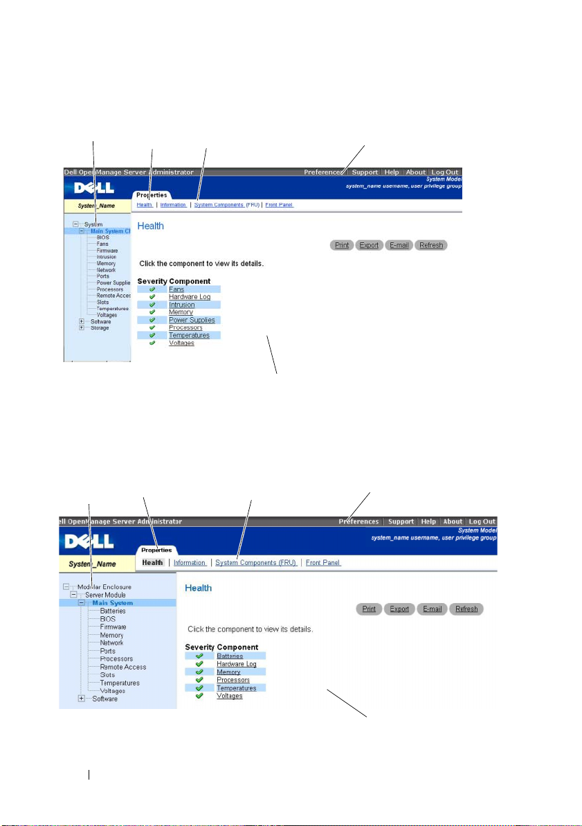
Figure 4-1. Sample Server Administrator Home Page — Non-Modular System
system tree
action tab
action tab subcategories
action window
global navigation bar
Figure 4-2 shows a sample Server Administrator home page layout for a user
logged in with administrator privileges on a modular system.
Figure 4-2. Sample Server Administrator Home Page — Modular System
system tree
action tab subcategoriesaction tab
global navigation bar
28 Using Server Administrator
action window
Page 29

Clicking an object in the system tree opens a corresponding action window
for that object. You can navigate in the action window by clicking action tabs
to select major categories and clicking the action tab subcategories to access
more detailed information or more focused actions. The information
displayed in the data area of the action window can range from system logs to
status indicators to system probe gauges. Underlined items in the data area of
the action window indicate a further level of functionality. Clicking an
underlined item creates a new data area in the action window that contains a
greater level of detail. For example, clicking Main System Chassis/Main
System under the Health subcategory of the Properties action tab lists the
health status of all the components contained in the Main System
Chassis/Main System object that are monitored for health status.
NOTE: Administrator or Power User privileges are required to view most of the
system tree objects, system components, action tabs, and data area features that
are configurable. Additionally, only users logged in with Administrator privileges
can access critical system features such as the shutdown functionality included
under the Shutdown tab.
Global Navigation Bar
The global navigation bar and its links are available to all user levels in
the program.
• Clicking
Preferences Home Page."
• Clicking
• Clicking
the Online Help."
• Clicking
information.
• Clicking
Preferences
Support
Help
About
Log Out
opens the
Preferences
home page. See "Using the
connects you to the Dell Support website.
opens the context-sensitive online help window. See "Using
displays Server Administrator version and copyright
ends your current Server Administrator program session.
Using Server Administrator 29
Page 30

System Tree
The system tree appears on the left side of the Server Administrator home
page and lists the components of your system that are viewable. The system
components are categorized by component type. When you expand the main
object known as Modular Enclosure
categories of system/server module components that may appear are
Main System Chassis/Main System, Software, and Storage.
To expand a branch of the tree, click the plus sign ( ) to the left of an object,
or double-click the object. A minus sign ( ) indicates an expanded entry
that cannot be expanded further.
→
System/Server Module, the major
Action Window
When you click an item on the system tree, details about the component or
object appear in the data area of the action window. Clicking an action tab
displays all available user options as a list of subcategories.
Clicking an object on the system/server module tree opens that component's
action window, displaying the available action tabs. The data area defaults to
a preselected subcategory of the first action tab for the selected object.
The preselected subcategory is usually the first option. For example,
clicking the Main System Chassis/Main System object opens an action
window in which the Properties action tab and Health subcategory are
displayed in the window's data area.
Data Area
The data area is located below the action tabs on the right side of the
home page. The data area is where you perform tasks or view details about
system components. The content of the window depends on the system tree
object and action tab that are currently selected. For example, when you
select BIOS from the system tree, the Properties tab is selected by default
and the version information for the system BIOS appears in the data area.
The data area of the action window contains many common features,
including status indicators, task buttons, underlined items, and gauge
indicators.
System/Server Module Component Status Indicators
The icons that appear next to component names show the status of that
component (as of the latest page refresh).
30 Using Server Administrator
Page 31

Table 4-2. System/Server Module Component Status Indicators
A green check mark indicates that a component is healthy (normal).
A yellow triangle containing an exclamation point indicates that a
component has a warning (noncritical) condition. A warning condition
occurs when a probe or other monitoring tool detects a reading for a
component that falls within certain minimum and maximum values.
A warning condition requires prompt attention.
A red X indicates that a component has a failure (critical) condition.
A critical condition occurs when a probe or other monitoring tool detects
a reading for a component that falls within certain minimum and maximum
values. A critical condition requires immediate attention.
A blank space indicates that a component's health status is unknown.
Task Buttons
Most windows opened from the Server Administrator home page contain at
least four task buttons: Print, Export, Email, and Refresh. Other task buttons
are included on specific Server Administrator windows. Log windows, for
example, also contain Save As and Clear Log task buttons. For specific
information about individual task buttons, click Help on any Server
Administrator home page window to view detailed information about the
specific window you are viewing.
• Clicking
• Clicking
Print
prints a copy of the open window to your default printer.
Export
generates a text file that lists the values for each data field
on the open window. The export file is saved to a location you specify.
See "Setting User and System Preferences" for instructions on customizing
the delimiter separating the data field values
• Clicking
Email
creates an e-mail message addressed to your designated
.
e-mail recipient. See "Setting User and System Preferences" for
instructions on setting up your e-mail server and default e-mail recipie
• Clicking
Refresh
reloads the system component status information in the
nt.
action window data area.
Using Server Administrator 31
Page 32

• Clicking
• Clicking
Save As
saves an HTML file of the action window in a
Clear Log
.zip
file.
erases all events from the log displayed in the action
window data area.
NOTE: The Export, Email, Save As, and Clear Log buttons are only visible for users
logged in with Power User or Administrator privileges.
Underlined Items
Clicking an underlined item in the action window data area displays additional
details about that item.
Gauge Indicators
Temperature probes, fan probes, and voltage probes are each represented by a
gauge indicator. For example, Figure 4-3 shows readings from a system's CPU
fan probe.
Figure 4-3. Gauge Indicator
32 Using Server Administrator
Page 33

Using the Online Help
Context-sensitive online help is available for every window of the Server
Administrator home page. Clicking Help on the global navigation bar opens
an independent help window that contains detailed information about the
specific window you are viewing. The online help is designed to help guide
you through the specific actions required to perform all aspects of the Server
Administrator services. Online help is available for all windows you can view,
based on the software and hardware groups that Server Administrator
discovers on your system and your user privilege level.
Using the Preferences Home Page
The left-hand pane of the Preferences home page (where the system tree is
displayed on the Server Administrator home page) displays all available
configuration options in the system tree window.
See Table 4-3 for available Preferences home page configuration options.
Table 4-3. Preferences Home Page Configuration Options
General Settings
Server Administrator
You can view the Preferences tab after you log in to manage a remote system.
This tab is also available when you log in to manage the Server Administrator
Web server.
Like the Server Administrator home page, the Preferences home page has
three main areas:
• The global navigation bar provides links to general services.
– Clicking
Administrator home page.
• The left-hand pane of the
displayed on the Server Administrator home page) displays the preference
categories for the managed system or the Server Administrator Web server.
• The action window displays the available settings and preferences for the
managed system or the Server Administrator Web Server.
Back to Server Administrator
Preferences
returns you to the Server
home page (where the system tree is
Using Server Administrator 33
Page 34

Figure 5-4 shows a typical Preferences home page layout.
Figure 4-4. Sample Preferences Home Page
Managed System Preferences
When you log in to a remote system, the Preferences home page defaults to
the Node Configuration window under the Preferences tab.
Click the Server Administrator object to enable or disable access to users with
User or Power User privileges. Depending on the user’s group privileges,
the Server Administrator object action window can have the Preferences tab.
Under the Preferences tab, you can:
• Enable or disable access to users with User or Power User privileges.
• Configure the Command Log Size.
Server Administrator Web Server Preferences
When you log in to manage the Server Administrator Web server,
the Preferences home page defaults to the User Preferences window under
the Preferences tab.
34 Using Server Administrator
Page 35

Dell Systems Management Server Administration Connection Service and
Security Setup
You can set user and system preferences and manage X.509 certificates when
you are logged in to the Server Administrator Web server. See "Managing
Server Administrator Web Server" for details. Once you log in to manage the
Server Administrator Web server, you can perform the following:
• Setting User and System Preferences
• X.509 Certificate Management
Setting User and System Preferences
You set user and secure port system preferences from the Preferences
home page.
NOTE: You must be logged in with Administrator privileges to set or reset user or
system preferences.
Log in to the Server Administrator Web server. Perform the following steps to
set up your user preferences:
Click
1
2
3
Preferences
Preferences
The
Click
General Settings
To add a preselected e-mail recipient, type the e-mail address of your
designated service contact in the
on the global navigation bar.
home page appears.
.
Mail To:
field, and click
Apply Changes
.
NOTE: Clicking Email in any window sends an e-mail message with an
attached HTML file of the window to the designated e-mail address.
4
To change the home page appearance, select an alternative value in the
skin
or
scheme
fields and click
Apply Changes
.
Perform the following steps to set up your secure port system preferences:
Log in to the
1
Server Administrator W
eb server. Click
Preferences
on the
global navigation bar.
The
2
Preferences
Click
General Settings
home page appears.
, and the
Web Server
tab.
Using Server Administrator 35
Page 36

3
In the
Server Preferences
•The
Session Timeout
window, set options as necessary.
feature can set a limit on the amount of time that
a Server Administrator session can remain active. Select the
radio button to allow Server Administrator to time out if there is no user
interaction for a specified number of minutes. Users whose session
times out must log in again to continue. Select the
Disable
to disable the Server Administrator session timeout feature.
•The
HTTPS Port
field specifies the secure port for Server Administrator.
The default secure port for Server Administrator is 1311.
NOTE: Changing the port number to an invalid or in-use port number might
prevent other applications or browsers from accessing Server Administrator
on the managed system. See the Dell OpenManage Installation and Security
User's Guide for the list of default ports.
• The
IP Address to Bind to
field specifies the IP address(es) for the
managed system that Server Administrator binds to when starting a
session. Select the
applicable for your system. Select the
All
radio button to bind to all IP addresses
Specific
radio button to bind to
a specific IP address.
NOTE: Changing the IP Address to Bind to value to a value other than All may
prevent other applications or browsers from accessing Server Administrator
on the managed system.
•The
SMTP Server name
and
DNS Suffix for SMTP Server
your company or organization's Simple Mail Transfer Protocol (SMTP)
and domain name server (DNS) suffix. To enable Server Administrator
to send e-mails, you must type the IP address and DNS suffix for the
SMTP Server for your company or organization in the appropriate fields.
Enable
radio button
fields specify
NOTE: For security reasons, your company or organization might not allow
e-mails to be sent through the SMTP server to outside accounts.
• The
Support Link
field specifies the URL for the business entity that
provides support for your managed system.
36 Using Server Administrator
Page 37

•The
•The
Custom Delimiter
the data fields in the files created using the
field specifies the character used to separate
Export
character is the default delimiter. Other options are
*, ~, ?, :,|
, and ,.
SSL Encryption
field specifies the encryption levels for the
button. The ;
!, @, #, $, %, ^
secured HTTPS sessions. The available encryption levels include
Negotiate
•
Auto Negotiate
128-bit or higher
: To allow connection from browser with any
.
and
encryption strength. The browser auto negotiates with the Server
Administrator web server and uses the highest available
encryption level for the session. Legacy browsers with weaker
encryption can connect to the Server Administrator.
•
128-bit or higher:
To allow connections from browsers with
128-bit or higher encryption strength. One of the following cipher
suites will be applicable based upon the browser for any
established sessions:
SSL_RSA_WITH_RC4_128_SHA
SSL_RSA_WITH_RC4_128_MD5
SSL_DHE_RSA_WITH_3DES_EDE_CBC_SHA
TLS_DHE_RSA_WITH_AES_128_CBC_SHA
SSL_RSA_WITH_3DES_EDE_CBC_SHA
TLS_RSA_WITH_AES_128_CBC_SHA
TLS_DHE_DSS_WITH_AES_128_CBC_SHA
SSL_DHE_DSS_WITH_3DES_EDE_CBC_SHA
NOTE: 128-bit or higher option does not allow connections from browsers
with lower SSL encryption strength, such as 40 bit, 56 bit.
,
Auto
NOTE: Restart the Server Administrator web server for the changes to take effect.
NOTE: If the encryption level is set to 128-bit or higher, you can access or modify
the Server Administrator settings using a browser with the same or higher
encryption levels.
4
When you finish setting options in the
Apply Changes
.
Server Preferences
Using Server Administrator 37
window, click
Page 38

X.509 Certificate Management
Web certificates are necessary to ensure the identity of a remote system and
ensure that information exchanged with the remote system cannot be viewed or
changed by others. To ensure system security, it is strongly recommended that:
• You generate a new X.509 certificate, reuse an existing X.509 certificate,
or import a root certificate or certificate chain from a Certification
Authority (CA).
• All systems that have Server Administrator installed have unique
host names.
NOTE: You must be logged in with Administrator privileges to perform certificate
management.
To manage X.509 certificates through the Preferences home page, log in to
the Server Administrator Web server, click General Settings, click the
Web S er ver tab, and click X.509 Certificate.
You can use this option to:
•
Generate a new X.509 certificate
for access to Server Administrator.
•
Reuse an existing X.509 certificate
certificate that your company has title to, and uses this certificate to
control access to Server Administrator.
•
Import a root certificate
certificate, as well as the certificate response (in PKCS#7 format),
received from the trusted certificate authority.
•
Import certificate chain from a CA
certificate response (in PKCS#7 format) from the trusted certificate
authority. Some of the reliable certificate authorities are Verisign, Thawte,
and Entrust.
- This option allows you to import the root
- Use this option to create a certificate
- This option selects an existing
- This option allows you to import the
Controlling Server Administrator
Server Administrator Web Server automatically starts each time you reboot
the managed system. To manually start, stop, or restart Server Administrator
Web Server, use the following instructions.
NOTE: To control Server Administrator Web Server, you must be logged in with
administrator privileges.
38 Using Server Administrator
Page 39

Starting Server Administrator Web Server
Supported Microsoft Windows Operating Systems
To start Server Administrator Web Server on systems running a supported
Microsoft Windows operating system, perform the following steps:
1
Open the
2
Right-click the
(DSM SA) Connection Service
3
Click
Start
Services
.
window.
Dell Systems Management Server Administration
icon.
Stopping Server Administrator Web Server
Supported Microsoft Windows Operating Systems
To stop Server Administrator Web Server, perform the following steps:
Open the
1
2
Right-click the
3
Click
Stop
Services
.
window.
DSM SA Connection Service
icon.
Restarting Server Administrator Web Server
Supported Microsoft Windows Operating Systems
To restart Server Administrator Web Server, perform the following steps:
1
Open the
2
Right-click the
3
Click
Services
Restart
window.
DSM SA Connection Service
.
icon.
Using Server Administrator 39
Page 40

40 Using Server Administrator
Page 41

Server Administrator Services
Overview
The Server Administrator Instrumentation Service monitors the health of a
system and provides rapid access to detailed fault and performance information
gathered by industry standard systems management agents. The reporting
and viewing features allow retrieval of overall health status for each chassis
that comprises your system. At the subsystem level, you can view information
about the voltages, temperatures, fan rpm, and memory function at key
points in the system. A detailed account of every relevant cost of ownership
(COO) detail about your system can be seen in the summary view. Version
information for BIOS, firmware, operating system, and all installed systems
management software is easy to retrieve.
Additionally, system administrators can use the Instrumentation Service to
perform the following essential tasks:
• Specify minimum and maximum values for certain critical components.
The values, called thresholds, determine the range in which a warning
event for that component occurs (minimum and maximum failure values
are specified by the system manufacturer).
• Specify how the system responds when a warning or failure event occurs.
Users can configure the actions that a system takes in response to
notifications of warning and failure events. Alternatively, users who have
around-the-clock monitoring can specify that no action is to be taken and
rely on human judgment to select the best action in response to an event.
• Populate all of the user-specifiable values for the system, such as the name
of the system, the phone number of the system's primary user, the
depreciation method, whether the system is leased or owned, and so on.
Server Administrator Services 41
Page 42

Managing Your System
The Server Administrator home page defaults to the System object of the
system tree view. The default for the System object opens the Health
components under the Properties tab.
NOTE: For detailed information on every window of Server Administrator, see the
context-sensitive online help.
NOTE: Administrator or Power User privileges are required to view many of the
system tree objects, system components, action tabs, and data area features that
are configurable. Additionally, only users logged in with Administrator privileges
can access critical system features such as the shutdown functionality included
under the Shutdown tab.
Managing System/Server Module Tree Objects
The Server Administrator system/server module tree displays all visible system
objects based on the software and hardware groups that Server Administrator
discovers on the managed system and on the user's access privileges. The
system components are categorized by component type. When you expand
the main object—"Modular Enclosure"—"System/Server Module"—the
major categories of system components that may appear are, "Main System
Chassis/Main System," "Software," and "Storage."
If Storage Management Service is installed, depending on the controller and
storage attached to the system, the Storage tree object will expand to display
various objects.
For detailed information on the Storage Management Service component, see
the Dell OpenManage Server Administrator Storage Management User's Guide.
42 Server Administrator Services
Page 43

Server Administrator Home Page System Tree Objects
Unsupported Features in OpenManage Server Administrator
Due to the limitations of the VMware ESXi version 3.5 operating system,
some features available with earlier versions of OpenManage Server
Administrator are not available in this release. These are:
• Alert Management - Alert Actions
• Alert Management - SNMP Traps
xx1x
• BIOS Setup - Boot Sequence (Only on
• BIOS Setup - Trusted Platform Module (TPM) Security
• Network Interface - MAC Address
• Network Interface - Internet Protocol (IP) Address
• Network Interface - Operational status
• Network Interface - Maximum Transfer Unit size
• Network Interface - DMA
• Network Interface - Administrative status
• Preferences - SNMP Configuration
• Remote Shutdown - Power Cycle System with Shutdown OS First
• Power Management - Profiles
• Processors - Capabilities - Demand Based Switching(DBS) (Only on
systems for this release)
systems for this release)
xx1x
Modular Enclosure
NOTE: For the purposes of Server Administrator, "modular enclosure" refers to a
system that may contain one or more modular systems that appear as a separate
Server Module in the system tree. Like a stand-alone Server Module, a Modular
Enclosure contains all of the essential components of a system. The only difference
is that there are slots for at least two Server Modules within a larger container, and
each of them is as complete a system as a Server Module.
To view the modular system’s Chassis information and
Controller (CMC) information, click
the Modular Enclosure object
Server Administrator Services 43
Chassis Management
.
Page 44

Properties
Subtabs: Information
Under the Properties tab, you can:
• View the chassis information for the modular system being monitored.
• View detailed Chassis Management Controller (CMC) information for the
modular system being monitored.
Accessing and Using Chassis Management Controller
To link to the Chassis Management Controller Log in window from the
Server Administrator home page, click the Modular Enclosure object, click
the CMC Information tab, and then click Launch the CMC Web Interface.
The CMC Log in window appears. After connecting to the CMC you can
monitor and manage your modular enclosure.
System/Server Module
The System/Server Module object contains three main system component
groups: "Main System Chassis/Main System," "Software," and "Storage."
The Server Administrator home page defaults to the System object of the
system tree view. Most administrative functions can be managed from the
System/Server Module object action window. The System/Server Module
object action window has the following tabs, depending on the user's group
privileges: Properties, Shutdown, Logs, Alert Management, and Session
Management.
The Session Management tab can be viewed once you log in to manage the
Server Administrator Web server. See "Managing Server Administrator Web
Server" for details on logging in.
Properties
Subtabs: Health | Summary | Asset Information | Auto Recovery
Under the Properties tab, you can:
• View the current health alert status for hardware and software components
in the
Main System Chassis/Main System
• View detailed summary information for all components in the system
being monitored.
object andthe
Storage
object.
44 Server Administrator Services
Page 45

• View and configure asset information for the system being monitored.
• View and set the Automatic System Recovery (OS watchdog timer) actions
for the system being monitored.
NOTE: Automatic System Recovery options may not be available because the
operating system watchdog timer is enabled in BIOS. To configure the auto
recovery options, the operating system watchdog timer must be disabled.
NOTE: Automatic System Recovery actions may not execute exactly per the
time-out period (n seconds) when the watchdog identifies a system that has
stopped responding. The action execution time ranges from n-h+1 to n+1
seconds, where n is the time-out period and h is the heart beat interval.
The value of the heart beat interval is 7 seconds when n <= 30 and 15 seconds
when n > 30.
NOTE: The functionality of the watchdog timer feature cannot be guaranteed
when an uncorrectable memory event occurs in the system DRAM Bank_1.
If an uncorrectable memory event occurs in this location, the BIOS code
resident in this space may become corrupted. Because the watchdog feature
uses a call to BIOS to effect the shutdown or reboot behavior, the feature may
not work properly. If this occurs, you must manually reboot the system.
Shutdown
Subtabs: Remote Shutdown | Thermal Shutdown | Web Server Shutdown
The Web Server Shutdown tab can be accessed only when you are logged in
to the Server Administrator Web Server. See "Managing Server Administrator
Web Server" for details.
Under the Shutdown tab, you can:
• Configure the operating system shutdown and remote shutdown options.
• Set the thermal shutdown severity level to shut down your system in the
event that a temperature sensor returns a warning or failure value.
NOTE: A thermal shutdown occurs only when the temperature reported by
the sensor goes above the temperature threshold. A thermal shutdown does
not occur when the temperature reported by the sensor goes below the
temperature threshold.
• Shut down the DSM SA Connection Service (Web server).
NOTE: The DSM SA Connection Service starts automatically after a reboot,
so you must shut down the DSM SA Connection Service every time a system
starts up.
Server Administrator Services 45
Page 46

Logs
Subtabs: Hardware | Alert | Command
Under the Logs tab, you can:
• View the Embedded System Management (ESM) log or the System Event
Log (SEL) for a list of all events related to your system's hardware
components. The status indicator icon next to the log name will change
from normal status ( ) to noncritical status( ) when the log file
reaches 80 percent capacity. On Dell™ PowerEdge™
x8xx, x9xx
and
xx1x
systems, the status indicator icon next to the log name will change to
critical status ( ) when the log file reaches 100 percent capacity.
NOTE: Dell recommends that you clear the hardware log when it reaches
80 percent capacity. If the log is allowed to reach 100 percent capacity, the
latest events are discarded from the log.
• View the Alert log for a list of all events generated by the Server
Administrator Instrumentation Service and Storage Management Service
in response to changes in the status of sensors and other
monitored parameters.
NOTE: See the Server Administrator Messages Reference Guide for a
complete explanation of each alert event ID's corresponding description,
severity level, and cause.
• View the Command log for a list of each command executed from the
Server Administrator
home page.
NOTE: See "Server Administrator Logs" for complete instructions on viewing,
printing, saving, and e-mailing logs.
Alert Management
Subtabs: Platform Events
Under the Alert Management tab, you can:
• View current alert actions settings and set the alert actions that you want
to be performed in the event that a system component sensor returns a
warning or failure value.
46 Server Administrator Services
Page 47

Session Management
The Session Management tab can be accessed only when you are logged in to
the Server Administrator Web Server. See 'Managing Server Administrator
Web Server' for details.
Subtabs: Session
Under the Session Management tab, you can:
• View session information for current users that have logged in to Server
Administrator.
• Terminate user sessions.
NOTE: Only users with administrative privileges can view the Session
Management page and terminate session(s) of logged-in users.
Main System Chassis/Main System
Click the Main System Chassis/Main System object to manage your system's
essential hardware and software components.
The available components are:
– AC Switch
– Batteries
–BIOS
–Fans
– Firmware
– Hardware Performance
– Intrusion
–Memory
– Network
–Ports
– Power Management
– Power Supplies
– Processors
– Remote Access
Server Administrator Services 47
Page 48

–Slots
– Temperatures
– Voltages
NOTE: AC Switch is supported on limited systems, Batteries is supported only
on Dell PowerEdge x9xx and Dell xx0x systems, Hardware Performance is
supported only on Dell xx0x systems, Power Management is supported on
limited Dell xx0x systems, while Power Supplies is not available on Dell
PowerEdge 1900 systems.
The system/server module may contain one main system chassis or several
chassis. The main system chassis/main system contains the essential
components of a system. The Main System Chassis/Main System object
action window has the following tab: Properties.
Properties
Subtabs: Health | Information | System Components (FRU)| Front Panel
Under the Properties tab, you can:
• View the health or status of hardware components and sensors. Each listed
component has a "System/Server Module Component Status Indicators"
icon next to its name. A green check mark ( ) indicates that a
component is healthy (normal). A yellow triangle containing an
exclamation point ( ) indicates that a component has a warning
(noncritical) condition and requires prompt attention. A red X ( )
indicates a component has a failure (critical) condition and requires
immediate attention. A blank space ( ) indicates that a component's
health status is unknown. The available monitored components include:
– AC Switch
– Batteries
–Fans
– Hardware Log
–Intrusion
–Memory
– Power Management
– Power Supplies
– Processors
48 Server Administrator Services
Page 49

–Temperatures
– Voltages
• View information about the main system chassis attributes.
• View detailed information about the field-replaceable units (FRUs)
installed in your system (under the
System Components (FRU)
subtab.)
• Enable or disable the managed system's front panel buttons, namely Power
button and Non-Masking Interrupt (NMI) button (if present on the
system).
AC Switch
Click the AC Switch object to display key features of your system's AC
failover switch. The AC Switch object action window can have the following
tab, depending on the user's group privileges: Properties.
Properties
Subtab: Information
Under the Properties tab, you can view AC switch redundancy information
and view information about the AC power lines.
Batteries
Click the Batteries object to view information about your system’s installed
batteries. Batteries maintain the time and date when your system is turned
off. The battery saves the system’s BIOS setup configuration, which allows
the system to reboot efficiently. The Batteries object action window can have
the following tabs, depending on the user’s group privileges.
Properties
Subtab: Information
Under the Properties tab, you can view the current readings and status of
your system’s batteries.
BIOS
Click the BIOS object to manage key features of your system's BIOS. Your
system’s BIOS contains programs stored on a flash memory chip set that
control communications between the microprocessor and peripheral devices,
such as the keyboard and the video adapter, and other miscellaneous functions,
Server Administrator Services 49
Page 50

such as system messages. The BIOS object action window can have the
following tabs, depending on the user's group privileges: Properties and
Setup.
Properties
Subtab: Information
Under the Properties tab, you can view BIOS information.
Setup
Subtab: BIOS
Under the Setup tab, you can set the state for each BIOS setup object.
NOTE: Setting the boot sequence to Device List on the Setup tab results in the
following boot sequence: diskette, IDE CD drive, hard drive, option ROMs (if the
devices are available).
You can modify the state of many BIOS setup features including but not
limited to the Serial Port, Network Interface Controller cards, Boot Sequence,
User Accessible USB Ports, CPU Virtualization Technology, CPU
HyperThreading, AC Power Recovery Mode, Embedded SATA Controller,
Console Redirection, and Console Redirection Failsafe Baud Rate. You can
also configure internal USB device, Trusted Platform Module (TPM) settings,
optical drive controller settings, automatic system recovery (ASR) Watchdog
Timer, embedded hypervisor and additional LAN network ports on
motherboard information.
Depending upon your specific system configuration, additional setup items
may be displayed. However, some BIOS setup options may be shown on the
F2 BIOS Setup screen that are not accessible in Server Administrator.
NOTE: The NIC configuration information within the Server Administrator BIOS
setup may be inaccurate for embedded NICs. Using the BIOS setup screen to
enable or disable NICs might produce unexpected results. It is recommended that
you perform all configurations for embedded NICs through the actual System Setup
screen that is available by pressing <F2> while a system is booting.
NOTE: The BIOS Setup tab for your system only displays the BIOS features that are
supported on your system.
50 Server Administrator Services
Page 51

Fans
Click the Fans object to manage your system fans. Server Administrator
monitors the status of each system fan by measuring fan rpms. Fan probes
report rpms to the Server Administrator Instrumentation Service. When you
select Fans from the device tree, details appear in the data area in the
right-hand pane of the Server Administrator home page. The Fans object
action window can have the following tabs, depending on the user's group
privileges.
Properties
Subtabs: Fan Probes | Fan Control
Under the Properties tab, you can:
• View the current readings for your system's fan probes and configure
minimum and maximum values for fan probe warning threshold.
NOTE: Some fan probe fields differ according to the type of firmware your
system has: BMC or ESM. Some threshold values are not editable on
BMC-based systems.
• Select fan control options.
Firmware
Click the Firmware object to manage your system firmware. Firmware
consists of programs or data that have been written to ROM. Firmware can
boot and operate a device. Each controller contains firmware that helps
provide the controller's functionality. The Firmware object action window can
have the following tab, depending on the user's group privileges: Properties.
Properties
Subtab: Information
Under the Properties tab, you can view your system's firmware information.
Hardware Performance
Click the Hardware Performance object to view the status and cause for the
system’s performance degradation. The Hardware Performance object action
window can have the following tab, depending on the user's group privileges:
Server Administrator Services 51
Page 52

Properties.
Table 5-1 lists the possible values for status and cause of a probe:
Table 5-1. Possible Values for Status and Cause of a Probe
Status Values Cause Values
Degraded User Configuration
Insufficient Power Capacity
Unknown Reason
Normal [N/A]
Properties
Subtab: Information
Under the Properties tab, you can view the details of system’s performance
degradation.
Intrusion
Click the Intrusion object to manage your system's chassis intrusion status.
Server Administrator monitors chassis intrusion status as a security measure
to prevent unauthorized access to your system's critical components. Chassis
intrusion indicates that someone is opening or has opened the cover to the
system's chassis. The Intrusion object action window can have the Properties
tab depending on the user's group privileges.
Properties
Subtab: Intrusion
Under the Properties tab, you can view the chassis intrusion status.
Memory
Click the Memory object to manage your system's memory devices. Server
Administrator monitors the memory device status for each memory module
present in the monitored system. Memory device prefailure sensors monitor
memory modules by counting the number of ECC memory corrections.
Server Administrator also monitors memory redundancy information if your
system supports this feature. The Memory object action window can have the
Properties tab depending on the user's group privileges.
52 Server Administrator Services
Page 53

Properties
Subtab: Memory
Under the Properties tab, you can view memory attributes, memory device
details, and memory device status.
NOTE: If a system with spare bank memory enabled enters a redundancy lost state,
it may not be apparent which memory module is the cause. If you cannot determine
which DIMM to replace, see the switch to spare memory bank detected log entry in
the ESM system log to find which memory module failed.
Network
Click the Network object to manage your system's NICs. Server
Administrator monitors the status of each NIC present in your system to
ensure continuous remote connection. The Network object action window
can have the Properties tab, depending on the user's group privileges.
Properties
Subtab: Information
Under the Properties tab, you can view information about the NICs installed
on your system.
NOTE: In the 'IPv6 Addresses' section, Server Administrator will display only two
addresses, in addition to the link-local address.
Ports
Click the Ports object to manage your system's external ports. Server
Administrator monitors the status of each external port present in your system.
The Ports object action window can have the following tab, depending on the
user's group privileges: Properties.
Properties
Subtab: Information
Under the Properties tab, you can view information about your system's
internal and external ports.
Server Administrator Services 53
Page 54

Power Management
Monitoring
Subtabs: Consumption | Statistics
Under the Consumption tab you can view and manage your system’s Power
Consumption information in Watts and BTU/hr.
BTU/hr=Watt X 3.413 (Value rounded off to the nearest whole number)
Server Administrator monitors power consumption status, amperage, and
tracks power statistic details.
You can also view the System Instantaneous Headroom and System Peak
Headroom. The values are displayed in both Watts and BTU/hr (British
Thermal Unit). Power thresholds can be set in Watts and BTU/hr.
The Statistics tab allows you to view and reset your system’s Power tracking
statistics like energy consumption, system peak power, and system peak
amperage.
Management
Subtab: Budget
The Budget tab allows you to view the Power Inventory attributes like System
Idle Power and System Maximum Potential Power in Watts and BTU/hr. You
can also use the Power Budget option to Enable Power Cap and set the Power
Cap for your system.
Certain Power Management features may be available only on systems
enabled with the Power Management Bus (PMBus).
Power Supplies
Click the Power Supplies object to manage your system’s power supplies.
Server Administrator monitors power supply status, including redundancy, to
ensure that each power supply present in your system is functioning properly.
The Power Supplies object action window can have the following tabs,
depending on the user's group privileges.
54 Server Administrator Services
Page 55

Properties
Subtab: Elements
Under the Properties tab, you can:
• View information about your power supply redundancy attributes.
• Check the status of individual power supply elements, including the Rated
Input Wattage and Maximum Output Wattage. The Rated Input Wattage
attribute will be displayed only on PMBus systems starting xx1x.
Processors
Click the Processors object to manage your system's microprocessor(s).
A processor is the primary computational chip inside a system that controls
the interpretation and execution of arithmetic and logic functions. The
Processors object action window can have the Properties tabs depending on
the user's group privileges.
Properties
Subtab: Information
Under the Properties tab, you can view information about your system's
microprocessor(s) and access detailed capabilities and cache information.
Remote Access
Click the Remote Access object to manage the Baseboard Management
Controller (BMC) or Integrated Dell Remote Access Controller (iDRAC)
features and Remote Access Controller features.
Selecting Remote Access tab allows you to manage the BMC/iDRAC features
such as, general information on the BMC/iDRAC. You can also manage the
configuration of the BMC/iDRAC on a local area network (LAN), serial port
for the BMC/iDRAC, terminal mode settings for the serial port, BMC/iDRAC
on a serial over LAN connection, and BMC/iDRAC users.
NOTE: BMC is supported in Dell PowerEdge x8xx and x9xx systems and iDRAC is
supported in Dell xx0x and xx1x systems only.
NOTE: If an application other than Server Administrator is used to configure the
BMC/iDRAC while Server Administrator is running, the BMC/iDRAC configuration
data displayed by Server Administrator may become asynchronous with the
BMC/iDRAC. It is recommended that Server Administrator be used to configure the
BMC/iDRAC while Server Administrator is running.
Server Administrator Services 55
Page 56

DRAC allows you to access your system's remote system management
capabilities. The Server Administrator DRAC provides remote access to
inoperable systems, alert notification when a system is down, and the ability
to restart a system.
The Remote Access object action window can have the following tabs,
depending on the user's group privileges: Properties, Configuration, and Users.
Properties
Subtab: Information
Under the Properties tab, you can view general information on the remote
access device. You can also view the attributes of the IPv4 and IPv6 addresses.
Click Reset to Defaults to reset all the attributes to their system default
values.
Configuration
Subtabs: LAN | Serial Port | Serial Over LAN |Additional Configuration
Under the Configuration tab when BMC/iDRAC is configured, you can
configure the BMC/iDRAC on a LAN, serial port for BMC/iDRAC, and
BMC/iDRAC on a serial over LAN connection.
Under the Configuration tab, when DRAC is configured, you can:
• Configure network properties
NOTE: The Enable NIC, NIC Selection, and Encryption Key fields display only on
Dell PowerEdge x9xx systems.
Under the Additional Configuration tab you will be able to either enable or
disable IPv4/IPv6 properties.
NOTE: Enabling/disabling IPv4/IPv6 is possible only in a dual stack environment
(where both the IPv4 and IPv6 stacks are loaded).
56 Server Administrator Services
Page 57

Users
Subtab: Users
Under the Users tab, you can modify the remote access user configuration.
You can add, configure, and view information about Remote Access
Controller users.
NOTE: On the Dell PowerEdge x9xx systems:
• Ten user IDs are displayed. If a DRAC card is installed, sixteen
user IDs are displayed.
• Serial Over LAN Payload column is displayed.
Slots
Click the Slots object to manage the connectors or sockets on your system
board that accept printed circuit boards, such as expansion cards. The Slots
object action window has the Properties tab.
Properties
Subtab: Information
Under the Properties tab, you can view information about each slot and
installed adapter.
Temperatures
Click the Temperatures object to manage your system temperature in order to
prevent thermal damage to your system’s internal components. Server
Administrator monitors the temperature in a variety of locations in your
system's chassis to ensure that temperatures inside the chassis do not become
too high. The Temperatures object action window displays the Properties tab,
depending on the user's group privileges.
Server Administrator Services 57
Page 58

Properties
Subtab: Temperature Probes
Under the Properties tab, you can view the current readings and status for
your system's temperature probes and configure minimum and maximum
values for temperature probe warning threshold.
NOTE: Some temperature probe fields differ according to the type of firmware your
system has: BMC or ESM. Some threshold values are not editable on BMC-based
systems. When assigning probe threshold values, Server Administrator sometimes
rounds the minimum or maximum values you enter to the closest assignable value.
NOTE: Users can set minimum and maximum temperature probe threshold values for
an external chassis to whole numbers only. If users attempt to set either the minimum
or maximum temperature probe threshold value to a number that contains a decimal,
only the whole number before the decimal place is saved as the threshold setting.
Voltages
Click the Vo lt ag es object to manage voltage levels in your system. Server
Administrator monitors voltages across critical components in various chassis
locations in the monitored system. The Volt ages object action window can
have the Properties tabs depending on the user's group privileges.
Properties
Subtab: Voltage Probes
Under the Properties tab, you can view the current readings and status for
your system's voltage probes and configure minimum and maximum values
for voltage probe warning threshold.
NOTE: Some voltage probe fields differ according to the type of firmware your
system has: BMC or ESM. Some threshold values are not editable on
BMC-based systems.
58 Server Administrator Services
Page 59

Software
Click the Software object to view detailed version information about the
managed system's essential software components, such as the operating system
and the systems management software. The Software object action window has
the following tab, depending on the user's group privileges: Properties.
Properties
Subtab: Summary
Under the Properties tab, you can view a summary of the monitored system's
operating system and system management software.
Operating System
Click the Operating System object to view basic information about your
operating system. The Operating System object action window has the
following tab, depending on the user's group privileges: Properties.
Properties
Subtab: Information
Under the Properties tab, you can view basic information about your
operating system.
Storage
Server Administrator provides the Storage Management Service:
The Storage Management Service provides features for configuring storage
devices. In most cases, the Storage Management Service is installed using Typical
Setup.
When the Storage Management Service is installed, click the Storage object
to view the status and settings for various attached array storage devices,
system disks, and so on.
In the case of Storage Management Service, the Storage object action window
has the following tab, depending on the user's group privileges: Properties.
Properties
Subtab: Health
Under the Properties tab, you can view the health or status of attached
storage components and sensors such as array subsystems and operating
system disks.
Server Administrator Services 59
Page 60

60 Server Administrator Services
Page 61

Working With Remote Access Controller
NOTE: Baseboard Management Controller (BMC) is supported on Dell™
PowerEdge™ x8xx and x9xx systems and the Integrated Dell Remote Access
Controller (iDRAC) is supported on Dell xx0x and xx1x systems.
Overview
This chapter provides information on accessing and using the remote access
features of BMC/iDRAC and DRAC.
The Dell systems baseboard management controller (BMC)/Integrated Dell
Remote Access Controller (iDRAC) monitors the system for critical events by
communicating with various sensors on the system board and sends alerts and
log events when certain parameters exceed their preset thresholds. The
BMC/iDRAC supports the industry-standard Intelligent Platform
Management Interface (IPMI) specification, enabling you to configure,
monitor, and recover systems remotely.
The DRAC is a systems management hardware and software solution
designed to provide remote management capabilities, crashed system
recovery, and power control functions for Dell systems.
By communicating with the system’s baseboard management controller
(BMC)/ Integrated Dell Remote Access Card (iDRAC), the DRAC can be
configured to send you e-mail alerts for warnings or errors related to voltages,
temperatures, and fan speeds. The DRAC also logs event data and the most
recent crash screen (available only on systems running Microsoft
operating system) to help you diagnose the probable cause of a system crash.
The Remote Access Controller provides remote access to an inoperable
system, allowing you to get the system up and running as quickly as possible.
The Remote Access Controller also provides alert notification when a system
is down and allows you to remotely restart a system. Additionally, the Remote
Access Controller logs the probable cause of system crashes and saves the
most recent crash screen.
®
Windows®
Working with Remote Access Controller 61
Page 62

You can log in to the Remote Access Controller through the Server
Administrator home page or by directly accessing the controller's IP address
using a supported browser.
When using the Remote Access Controller, you can click Help on the global
navigation bar for more detailed information about the specific window you are
viewing. Remote Access Controller help is available for all windows accessible
to the user based on user privilege level and the specific hardware and software
groups that Server Administrator discovers on the managed system.
NOTE: See the Dell Remote Access Controller 4 User’s Guide for more information
on using DRAC 4 or Dell Remote Access Controller 5 User’s Guide for more
information on using DRAC 5.
NOTE: See the Dell OpenManage™ Baseboard Management Controller Utilities
.
User's Guide for more information about the BMC.
NOTE: See the Integrated Dell Remote Access Controller User’s Guide for detailed
.
information on configuring and using the iDRAC.
Table 6-1 lists the GUI field names and the applicable system, when Server
Administrator is installed on the system.
Table 6-1. System Availability for the Following GUI Field Names
GUI Field Name Applicable System
Modular Enclosure
Server module
Main System
System
Main system Chassis
Modular System
Modular System
Modular System
Non-Modular System
Non-Modular System
See the Dell™ OpenManage™ Server Administrator Installation Guide for
VMware® ESXi 3.5 for more information on the systems support for remote
access devices.
Server Administrator allows remote, in-band access to event logs, power
control, and sensor status information and provides the ability to configure
the BMC/iDRAC. You can manage BMC/iDRAC and DRAC through the
Server Administrator graphical user interface by clicking the Remote Access
object, which is a subcomponent of the Main System Chassis/Main System
group. You can perform the following tasks:
• View basic information
• Configure the remote access device on a LAN connection
62 Working with Remote Access Controller
Page 63

• Configure the remote access device on a serial over LAN connection
• Configure the remote access device on a serial port connection
• Configure Additional remote access device properties
• Configure users on the remote access device
• Set platform event filter alerts
You can view BMC/iDRAC or DRAC information based on which hardware is
providing the remote access capabilities for the system.
In addition, the Server Administrator Instrumentation Service allows you to
manage the Platform Event Filters (PEF) parameters and alert destinations.
NOTE: You can view BMC data on Dell PowerEdge x8xx and x9xx systems only.
Viewing Basic Information
You can view basic information about the BMC/iDRAC, IPv4 Address, and
DRAC. You can also reset the BMC settings to their default values. To do
this:
NOTE: You must be logged in with Administrator privileges to reset the BMC
settings.
Click the Modular Enclosure→ System/Server Module→ Main System
Chassis/Main System→ Remote Access object.
The Remote Access page displays the following base information of the
system’s BMC:
Remote Access Device
• Device type
• IPMI Version
• System GUID
• Number of Possible Active Sessions
• Number of Current Active Sessions
• LAN Enabled
• SOL Enabled
• MAC Address
Working with Remote Access Controller 63
Page 64

IPv4 Address
• IP Address Source
• IP Address
• IP Subnet
•IP Gateway
IPv6 Address
• IP Address Source
• IPv6 Address 1
• Default Gateway
• IPv6 Address 2
• Link Local Address
• DNS Address Source
• Preferred DNS Server
• Alternate DNS Server
NOTE: You will be able to view IPv4 and IPv6 address details only if you enable the
IPv4 and IPv6 address properties under Additional Configuration in the Remote
Access tab.
Configuring the Remote Access Device to use a LAN Connection
NOTE: The LAN configuration fields are displayed as read-only if they are
configured as disabled for inband users.
You can configure the remote access device for communication over a LAN
connection. To do this:
1
Click the
Chassis/Main System
2
Click the
64 Working with Remote Access Controller
Modular Enclosure→
→ Remote Access object.
Configuration
tab.
System/Server Module→
Main System
Page 65

3
Click
LAN
.
The
LAN Configuration
NOTE: BMC/iDRAC management traffic will not function properly if the LAN
on motherboard (LOM) is teamed with any network adapter add-in-cards.
4
Configure the following NIC configuration details:
window appears.
• Enable NIC (This option is available on Dell PowerEdge
and when DRAC is installed. Select this option for NIC teaming.
Dell PowerEdge
x9xx systems, you can team NICs for added
redundancy.)
NOTE: Your DRAC contains an integrated 10BASE-T/100BASE-T Ethernet NIC
and supports TCP/IP. The NIC has a default address of 192.168.20.1 and a
default gateway of 192.168.20.1.
NOTE: If your DRAC is configured to the same IP address as another NIC on
the same network, an IP address conflict occurs. The DRAC stops responding
to network commands until the IP address is changed on the DRAC. The DRAC
must be reset even if the IP address conflict is resolved by changing the IP
address of the other NIC.
NOTE: Changing the IP address of the DRAC causes the DRAC to reset. If
SNMP polls the DRAC before it initializes, a temperature warning is logged
because the correct temperature is not transmitted until the DRAC is initialized.
• NIC Selection
NOTE: NIC Selection cannot be configured on modular systems.
• Enable IPMI Over LAN
• IP Address Source
• IP Address
• Subnet Mask
• Gateway Address
• Channel Privilege Level Limit
• New Encryption Key (This option is available on Dell PowerEdge
systems.)
x9xx
systems
In
x9xx
Working with Remote Access Controller 65
Page 66

5
Configure the following optional VLAN configuration details:
NOTE: VLAN configuration is not applicable for systems with iDRAC.
• Enable VLAN ID
• VLAN ID
• Priority
6
Configure the following IPv4 Properties:
• IP Address Source
• IP Address
• Subnet Mask
• Gateway Address
7
Configure the following IPv6 Properties:
• IP Address Source
• IP Address
• Prefix Length
• Default Gateway
• DNS Address Source
• Preferred DNS Server
• Alternate DNS Server
NOTE: You will be able to configure the IPv4 and IPv6 address details only if
you enable the IPv4 and IPv6 properties under Additional Configuration.
8
Click
Apply Changes.
66 Working with Remote Access Controller
Page 67

Configuring the Remote Access Device to use a Serial Port Connection
You can configure the BMC for communication over a serial port connection.
To do this:
Click the
1
Chassis/Main System
2
Click the
3
Click
The
4
Configure the following details:
• Connection Mode Setting
• Baud Rate
• Flow Control
• Channel Privilege Level Limit
5
Click
6
Click
In the
settings for the serial port.
Terminal mode is used for Intelligent Platform Interface Management
(IPMI) messaging over the serial port using printable ASCII characters.
Terminal mode also supports a limited number of text commands to
support legacy, text-based environments. This environment is designed so
that a simple terminal or terminal emulator can be used.
Modular Enclosure→
→ Remote Access object.
Configuration
Serial Port
Serial Port Configuration
Apply Changes.
Terminal Mode Settings
Terminal Mode Settings
.
tab.
System/Server Module→
window appears.
.
window, you can configure terminal mode
Main System
7
Specify the following customizations to increase compatibility with
existing terminals:
• Line Editing
• Delete Control
• Echo Control
• Handshaking Control
Working with Remote Access Controller 67
Page 68

• New Line Sequence
• Input New Line Sequence
8
Click
Apply Changes
9
Click
Back To Serial Port Configuration Window
Serial Port Configuration
.
to go to back to the
window.
Configuring the Remote Access Device to use a Serial Over LAN Connection
You can configure the BMC/iDRAC for communication over a serial over
LAN (SOL) connection. To do this:
1
Click the
Chassis/Main System
2
Click the
3
Click
The
4
Configure the following details:
• Enable Serial Over LAN
•Baud Rate
• Minimum Privilege Required
5
Clic
6
Click
7
In the
may configure the following information:
• Character Accumulate Interval
• Character Send Threshold
8
Click
9
Click
Over LAN Configuration
Modular Enclosure→
→ Remote Access object.
Configuration
Serial Over LAN
Serial Over LAN Configuration
k Apply Changes.
Advanced Settings
Serial Over LAN Configuration Advanced Settings
Apply Changes.
Go Back to Serial Over LAN Configuration
tab.
.
System/Server Module→
window appears.
to further configure BMC.
to return to the
window.
Main System
window, you
Serial
68 Working with Remote Access Controller
Page 69

Additional Configuration for iDRAC
You can configure the IPv4 and IPv6 properties using the Additional
Configuration tab. To do this:
1
Click the
Chassis/Main System
2
Click the
3
Click
4
Configure the IPv4 and IPv6 properties as
5
Click
Modular Enclosure→
→ Remote Access
Configuration
Addtional Configuration.
Apply Changes.
tab.
System/Server Module→
object.
Enabled
or
Disabled
Main System
.
Configuring Remote Access Device Users
Remote access device users can be configured using the Remote Access page.
To access this page:
1
Click the
Chassis/Main System
2
Click the
The
can be configured as BMC/iDRAC users.
3
Click
The
specific BMC/iDRAC user.
Modular Enclosure→
→ Remote Access object.
Users
tab.
Remote Access Users
User ID
Remote Access User Configuration
to configure a new or existing BMC/iDRAC user.
System/Server Module→
window displays information about users that
Main System
window allows you to configure a
4
Specify the following general information:
• Select
• Enter the name for the user in the
• Select the
• Enter a new password in the
• Re-enter the new password in the
Enable User
Change Password
to enable the user.
check box.
New Password
Working with Remote Access Controller 69
User Name
Confirm New Password
field.
field.
field.
Page 70

5
Specify the following user privileges:
• Select the maximum LAN user privilege level limit.
• Select the maximum serial port user privilege granted.
x9xx
• On Dell PowerEdge
systems, select Enable Serial Over LAN to
enable Serial Over LAN.
6
Specify the following iDRAC user privileges.
7
Click
Apply Changes
8
Click
Back to Remote Access User Window
Access Users
NOTE: Six additional user entries are configurable when DRAC is installed.
window.
This results in a total of 16 users. The same username and password rules
apply to BMC/iDRAC and RAC users. When DRAC/iDRAC6 is installed, all the
16 users entries are allocated to DRAC.
to save changes.
to go back to the
Remote
Setting Platform Event Filter Alerts
You can use the Server Administrator Instrumentation Service to configure
the most relevant BMC features, such as Platform Event Filter (PEF)
parameters and alert destinations. To do this:
1
Click the
2
Click the
3
Click
The
specific platform events. You can select those events for which you want to
take shutdown actions and generate alerts for selected actions. You can
also send alerts to specific IP address destinations of your choice.
System
object.
Alert Management
Platform Events
Platform Events
tab.
.
window allows you to take individual action on
NOTE: You must be logged in with Administrator privileges to configure the
BMC Platform Event Filter Alerts.
NOTE: The Enable Platform Event Filters Alerts setting disables or enables
platform event filter alert generation. It is independent of the individual
platform event alert settings.
70 Working with Remote Access Controller
Page 71

NOTE: System Power Probe Warning and System Power Probe Failure are
not supported on Dell systems without PMBus support although Server
Administrator allows you to configure them.
NOTE: On Dell PowerEdge 1900 systems, the PS/VRM/D2D Warning,
PS/VRM/D2D Failure, and Power Supply Absent Platform Event Filters are not
supported even though Server Administrator allows you to configure these
Event Filters.
4
Choose the platform event for which you want to take shutdown actions or
generate alerts for selected actions and click
The
Set Platform Events
window allows you to specify the actions to be
Set Platform Events
.
taken if the system is to be shut down in response to a platform event.
5
Select one of the following actions:
•
None
Takes no action when the operating system is hung or has crashed.
Reboot System
•
Shuts down the operating system and initiates system startup,
performing BIOS checks and reloading the operating system.
•
Power Cycle System
Turns the electrical power to the system off, pauses, turns the power
on, and reboots the system. Power cycling is useful when you want to
reinitialize system components such as hard drives.
•
Power Off System
Turns off the electrical power to the system.
Power Reduction
•
Throttles the CPU.
CAUTION: If you select a Platform Event shutdown action other than None or
Power Reduction, your system will shut down forcefully when the specified event
occurs. This shutdown is initiated by firmware and is done without first shutting
down the operating system or any running applications.
6
Select the
7
Click
8
Click
Filters
Generate Alert
NOTE: To generate an alert, you must select both Generate Alert and the
Enable Platform Events Alerts settings.
Apply Changes
Go Back to Platform Events Page
check box for the alerts to be sent.
.
to go back to the
Platform Event
window.
Working with Remote Access Controller 71
Page 72

Setting Platform Event Alert Destinations
You can also use the Platform Event Filters window to select a destination
where an alert for a platform event is to be sent. Depending on the number of
destinations that are displayed, you can configure a separate IP address for
each destination address. A platform event alert will be sent to each
destination IP address that you configure.
1
Click
Configure Destinations
Configure Destinations
The
2
Click the number of the destination you want to configure.
NOTE: The number of destinations that you can configure on a given system
may vary.
3
Select the
4
Click
Enable Destination
Destination Number
destination. This IP address is the IP address to which the platform event
alert will be sent.
5
Enter a value in the
Community String
authenticate messages sent between a management station and a managed
system. The community string (also called the community name) is sent
in every packet between the management station and a managed system.
6
Click
7
Apply Changes
Click
Go Back to Platform Events Page
Filters
window.
.
in the
Platform Event Filters
window.
window displays a number of destinations.
check-box.
to enter an individual IP address for that
field to act as a password to
to go back to the
Platform Event
72 Working with Remote Access Controller
Page 73

Server Administrator Logs
Overview
Server Administrator allows you to view and manage hardware, alert, and
command logs. All users can access logs and print reports from the Server
Administrator home page. Users must be logged in with Administrator
privileges to clear logs or must be logged in with Administrator or Power User
privileges to e-mail logs to their designated service contact.
When viewing Server Administrator logs, you can click Help on the global
navigation bar for more detailed information about the specific window you
are viewing. Server Administrator log help is available for all windows
accessible to the user based on user privilege level and the specific hardware
and software groups that Server Administrator discovers on the
managed system.
Integrated Features
Clicking a column heading sorts by the column or changes the sort direction
of the column. Additionally, each log window contains several task buttons
that can be used for managing and supporting your system.
Log Window Task Buttons
• Click
• Click
• Click
• Click
• Click
• Click
See "Task Buttons" for additional information about using the task buttons.
Print
to print a copy of the log to your default printer.
Export
to save a text file containing the log data (with the values of
each data field separated by a customizable delimiter) to a destination you
specify.
Email
to create an e-mail message that includes the log content as
an attachment.
Clear Log
Save As
Refresh
to erase all events from the log.
to save the log content in a
to reload the log content in the action window data area.
.zip
file.
Server Administrator Logs 73
Page 74

Server Administrator Logs
Server Administrator provides the following logs:
• "Hardware Log"
• "Alert Log"
• "Command Log"
Hardware Log
Use the hardware log to look for potential problems with your system's
hardware components. On Dell PowerEdge™ x8xx, x9xx, and xx1x systems,
the hardware log status indicator will change to critical status ( ) when the
log file reaches 100 percent capacity. There are two available hardware logs,
depending on your system: the Embedded System Management (ESM) log
and the System Event Log (SEL). The ESM log and SEL are each a set of
embedded instructions that can send hardware status messages to systems
management software. Each component listed in the logs has a status
indicator icon next to its name. A green check mark ( ) indicates that a
component is healthy (normal). A yellow triangle containing an exclamation
point ( ) indicates that a component has a warning (noncritical) condition
and requires prompt attention. A red X ( ) indicates that a component has
a failure (critical) condition and requires immediate attention. A blank space
( ) indicates that a component's health status is unknown.
To access the hardware log, click System, click the Logs tab, and click
Hardware.
Information displayed in the ESM and SEL logs includes:
• The severity level of the event
• The date and time that the event was captured
• A description of the event
Maintaining the Hardware Log
The status indicator icon next to the log name on the Server Administrator
homepage will change from normal status ( ) to noncritical status ( )
when the log file reaches 80 percent capacity. Be sure to clear the hardware log
when it reaches 80 percent capacity. If the log is allowed to reach 100 percent
capacity, the latest events are discarded from the log.
74 Server Administrator Logs
Page 75

Alert Log
NOTE: If the Alert log displays invalid XML data (for example, when the XML data
generated for the selection is not well formed), click Clear Log and then redisplay
the log information.
Use the Alert log to monitor various system events. The Server Administrator
generates events in response to changes in the status of sensors and other
monitored parameters. Each status change event recorded in the Alert log
consists of a unique identifier called the event ID for a specific event source
category and an event message that describes the event. The event ID and
message uniquely describe the severity and cause of the event and provide
other relevant information such as the location of the event and the
monitored component's previous state.
To access the Alert log, click System, click the Logs tab, and click Alert.
Information displayed in the Alert log includes:
• The severity level of the event
• The event ID
• The date and time that the event was captured
• The category of the event
• A description of the event
NOTE: The log history may be required for future troubleshooting and diagnostic
purposes. Therefore, it is recommended that you save the log files.
See the Server Administrator Messages Reference Guide for detailed
information about alert messages.
Command Log
NOTE: If the Command log displays invalid XML data (for example, when XML data
generated for the selection is not well formed), click Clear Log and then redisplay
the log information.
Use the Command log to monitor all of the commands issued by Server
Administrator users. The Command log tracks logins, logouts, systems
management software initialization, and shutdowns initiated by systems
management software, and records the last time the log was cleared. The size
of the command log file can be specified as per your requirement.
Server Administrator Logs 75
Page 76

To access the Command log, click System, click the Logs tab, and click
Command.
Information displayed in the Command log includes:
• The date and time that the command was invoked
• The user that is currently logged in to the Server Administrator home page
• A description of the command and its related values
NOTE: The log history may be required for future troubleshooting and diagnostic
purposes. Therefore, it is recommended that you save the log files.
76 Server Administrator Logs
Page 77

Setting Alert Actions
BMC/iDRAC Platform Events Filter Alert Messages
All possible Platform Event Filter (PEF) messages along with a description of
each event is listed in Table 8-1.
Table 8-1. PEF Alert Events
Event Description
Fan Probe Failure The fan is running too slow or not at all.
Voltage Probe Failure The voltage is too low for proper operation.
Discrete Voltage Probe
Failure
Temperature Probe
Wa r ni n g
Temperature Probe
Failure
Chassis Intrusion
Detected
Redundancy (PS or Fan)
Degraded
Redundancy (PS or Fan)
Lost
Processor Warning A processor is running at less than peak performance or
Processor Failure A processor has failed.
PPS/VRM/DCtoDC
Warning
Power Supply/VRM/D2D
Failure
The voltage is too low for proper operation.
The temperature is approaching excessively high or low
limits.
The temperature is either too high or too low for proper
operation.
The system chassis has been opened.
Redundancy for the fans and/or power supplies has been
reduced.
No redundancy remains for the system's fans and/or power
supplies.
speed.
The power supply, voltage regulator module, or DC to DC
converter is pending a failure condition.
The power supply, voltage regulator module, or DC to DC
converter has failed.
Setting Alert Actions 77
Page 78

Table 8-1. PEF Alert Events (continued)
Event Description
Hardware log is full or
emptied
Automatic System
Recovery
System Power Probe
Warning
System Power Probe
Failure
Either an empty or a full hardware log requires
administrator attention.
The system is hung or is not responding and is taking an
action configured by Automatic System Recovery.
The power consumption is approaching the failure
threshold.
The power consumption has crossed the highest
acceptable limit and has resulted in a failure.
Understanding Service Names
The service executable and display names of the following services have
changed:
Table 8-2. Service Names
Purpose Service Name Previous Release
(prior to 5.0)
Web Server
Display Name Secure Port Server DSM SA Connection Service
Executable
Name
Scheduling or Notification
Display Name OM Common Services DSM SA Shared Services
Executable
Name
Omaws[32|64] dsm_om_connsvc[32|64]
Omsad[32|64] dsm_om_shrsvc[32|64]
78 Setting Alert Actions
Current Release
dsm_om_connsvc
dsm_om_shrsvc
Page 79

Troubleshooting
Login Failure Scenarios
You may not be able to login to the Managed System if:
• you enter an invalid/incorrect IP address.
• you enter incorrect credentials (user name and password).
• the Managed System is not powered on.
• the Managed System is not reachable due to an invalid IP address or a
DNS error.
• the Managed System has an untrusted certificate and you do not select the
"Ignore Certificate Warning" in the login page.
• Server Administrator services are not enabled on the VMware ESXi 3.5
system. See the
for VMware ESXi 3.5
Administrator Services on the VMware ESXi 3.5 system.
• the small footprint CIM broker daemon (SFCBD) service on the
VMware ESXi 3.5 system is not running.
• the Web Server Management Service on the managed system is not running.
Dell OpenManage Server Administrator Installation Guide
for information on how to enable Server
Troubleshooting 79
Page 80

Fixing a Faulty Server Administrator Installation on Supported Windows Operating Systems
To fix a faulty installation of Dell™ OpenManage™ Server Administrator:
Go to
1
Administrator
Add/remove programs
and select the
, click on
Repair
Dell OpenManage Server
option.
Or
Download the required version of Server Administrator from the support site.
1
Run the installation package (double click the MSI). This installs the package in
a maintenance mode. Choose the
option in the
Program Maintenance
Repair
screen.
OpenManage Server Administrator Services
This table lists the services used by OMSA to provide systems management
information and the impact of these services failing.
Tables A-1 and A-2 list the services used by Server Administrator to provide
systems management information and the impact of these services failing.
Table A-1. Server Administrator Web Server Service
Service Name Description Impact of failure Recovery
Mechanism
Windows: DSM
SA
Connection
Service
(This service is
installed with
the Server
Administrator
Web server.)
Provides
remote/local
access to
OMSA from
any system with
a supported
Web browser
and network
connection.
Provides remote/local
access to OMSA from
any system with a
supported Web
browser and network
connection.
Restart Service Critical
80 Troubleshooting
Severity
Page 81

Table A-2. Managed system services
Service Name Description Impact of failure Recovery
Mechanism
DSM SA Data
Manager
(dsm_sa_datam
gr32d)
(This service
runs on the
Managed
system.)
DSM SA Event
Manager
(dsm_sa_event
mgr32d)
(This service
runs on the
Managed
system.)
Monitors the
system, provides
quicker access to
detailed fault
and performance
information and
allows remote
administration
of monitored
systems,
including
shutdown,
startup, and
security.
Provides
operating system
and file event
logging service
for systems
management
and is also used
by event log
analyzers.
Users will not be able
to configure/view the
hardware level details
on GUI if these
services are not
running.
If this service is
stopped, event logging
features will not
function properly.
Restart
Management
Agents
Restart
Management
Agents
Severity
Critical
Warning
Troubleshooting 81
Page 82

82 Troubleshooting
Page 83

Frequently Asked Questions
This section lists the frequently asked questions about OpenManage™ Server
Administrator:
NOTE: These questions are not specific to this release of Server Administrator.
1
What is the minimum permission level a user would need to install
OMSA?
You need to have a minimum permission level of Administrator to install
OMSA. Power Users and Users do not have permissions to install OMSA.
2
Is there an upgrade path required to install OMSA?
For systems that have version 4.3, an upgrade path is not required. For
systems that have a version older than 4.3, you need to first upgrade to
version 4.3, and then again upgrade to a 5.x version (x indicates the version of
OMSA you want to upgrade to).
3
How do I determine what is the latest version of OMSA available for my
system?
Log on to: support.dell.com → Product Support → Manuals → Software →
Systems Management → Dell OpenManage Server Administrator
The latest documentation version reflects the version of OpenManage Server
Administrator available for you.
4
How do I know what version of OMSA is running on my system?
Ans: After logging in to Server Administrator, navigate to Properties →
Summary. You can find the version of Server Administrator installed on your
system in the Systems Management column.
5
Are there other ports users can use apart from 1311?
Ans: Yes, you can set your preferred https port. Navigate to Preferences →
General Settings → Web Server → HTTPS Port
Instead of Use default, click on the Use radio button to set your
preferred port.
Frequently Asked Questions 83
Page 84

Note that changing the port number to an invalid or in-use port number
might prevent other applications or browsers from accessing Server
Administrator on the managed system. See the Dell OpenManage Installation
and Security User's Guide for the list of default ports.
6
Can I install OMSA on Fedora, College Linux, Mint, Ubuntu, Sabayon
or PClinux?
Ans: No, Server Administrator does not support any of these Operating
Systems.
7
Can OMSA send e-mails when there is a problem?
Ans: No, Server Administrator is not designed to send e-mails when there is a
problem.
8
Is SNMP Required for ITA Discovery, inventory and software updates on
PowerEdge™
systems? Can CIM be used by itself for discovery, inventory,
and updates or is SNMP required?
ITA communicating with Linux systems:
SNMP is required on the Linux system for discovery, status polling and
inventory.
Dell software updates are done through an SSH session and secure FTP and
root level permissions/credentials are required for this discrete action and
asked for when the action is setup or requested. Credentials from the
discovery range are not assumed.
ITA communicating with Windows systems:
For servers (systems running Windows Server operating systems), the system
may be configured with either or both of SNMP and CIM for discovery
by ITA. Inventory requires CIM.
Software updates, as in Linux, are not related to discovery and polling and the
protocols used.
Using adminstrator level credentials asked for at the time the update is
scheduled or performed, an administrative (drive) share is established to a
drive on the target system, and file(s) copying from somewhere (possibly
another network share) is done to the target system. WMI functions are then
invoked to execute the software update.
For clients/workstations, OMSA is not installed, so CIM discovery is used
when the target is running the OpenManage Client Instrumentation.
84 Frequently Asked Questions
Page 85

For many other devices such as network printers, the standard is still SNMP
to communicate with (primarily discover) the device.
Devices such as EMC storage have proprietary protocols. Some information
about this environment can be gathered from looking at the ports used tables
in the OpenManage documentation.
9
Are there any plans for SNMP v3 support?
No, there are no plans for SNMP v3 support in this release.
Will an Underscore character in the domain name cause Server Admin
10
login issues?
Yes, an underscore character in the domain name is invalid. All other
special characters (except the hyphen) are invalid too. You should use only
case-insensitive alphabets and numerals.
Frequently Asked Questions 85
Page 86

86 Frequently Asked Questions
Page 87

Glossary
The following list defines or identifies technical terms, abbreviations, and acronyms
used in your system documents.
authentication
The Server Administrator remote access controller has two methods of
authenticating user access:
RAC authentication and local operating system authentication. RAC authentication
is always enabled. Administrators can set up specific user accounts and passwords
that allow access to the RAC.
Operating systems also require administrators to define different levels of users
and user accounts; each user level has different privileges. Local operating system
authentication on the RAC is an option for administrators who do not want to
define one set of privileges for users in the operating system and a separate set of
users and accounts for the RAC. If you enable local operating system
authentication for the RAC, you enable any user with Administrator status on
the operating system to log in to the RAC.
baud rate
A measurement of data transmission speed. For example, modems are designed
to transmit data at one or more specified baud rate(s) through the COM (serial)
port of a system.
BMC
Abbreviation for baseboard management controller, which is a controller that
provides the intelligence in the IPMI structure.
BTU
Abbreviation for British thermal unit.
CA
Abbreviation for certification authority.
capability
Refers to the actions that an object can perform, or actions that can be taken on
a managed object. For example, if a card is hot-pluggable, it is capable of being
replaced while the system power is on.
Glossary 87
Page 88

CHAP
Acronym for Challenge-Handshake Authentication Protocol, an authentication
scheme used by PPP servers to validate the identity of the originator of the
connection upon connection or any time later.
CIM
Acronym for Common Information Model, which is a model for describing
management information from the DMTF. CIM is implementation independent,
allowing different management applications to collect the required data from a
variety of sources. CIM includes schemas for systems, networks, applications and
devices, and new schemas will be added. It provides mapping techniques for
interchange of CIM data with MIB data from SNMP agents.
CMC
Acronym for Chassis Management Controller.
controller
A chip that controls the transfer of data between the microprocessor and memory
or between the microprocessor and a peripheral device such as a disk drive or the
keyboard.
control panel
The part of the system that contains indicators and controls, such as the power
switch, hard drive access indicator, and power indicator.
cooling unit
Sets of fans or other cooling devices in a system chassis.
DBPM
Abbreviation for Demand Based Power Management.
DHCP
Abbreviation for Dynamic Host Configuration Protocol, a protocol that provides
a means to dynamically allocate IP addresses to computers on a LAN.
DIMM
Acronym for dual in-line memory module. A small circuit board containing
DRAM chips that connects to the system board.
88 Glossary
Page 89

DMTF
Abbreviation for Distributed Management Task Force, a consortium of
companies representing hardware and software providers that develops and
maintains standards for systems management of IT environments in enterprises
and the Internet.
DRAC 4
Acronym for Dell™ Remote Access Controller 4.
DRAC 5
Acronym for Dell Remote Access Controller 5.
DRAM
Acronym for dynamic random-access memory. A system's RAM is usually made
up entirely of DRAM chips. Because DRAM chips cannot store an electrical charge
indefinitely, your system continually refreshes each DRAM chip in the system.
DSM SA Connection Service
Acronym for Dell Systems Management Server Administration. An application
that makes Web pages available for viewing by Web browsers using the HTTPS
protocol. See "Web server".
ECC
Abbreviation for error checking and correction.
Embedded Hypervisor
See
Internal USB
EMC
Abbreviation for electromagnetic compatibility.
EMI
Abbreviation for electromagnetic interference.
EMM
Abbreviation for expanded memory manager. A utility that uses extended
memory to emulate expanded memory on systems with an Intel386™ or higher
microprocessor.
ERA
Abbreviation for embedded remote access.
Glossary 89
Page 90

ERA/MC
Abbreviation for embedded remote access modular computer. See modular system.
ERA/O
Abbreviation for embedded remote access option.
ESM
Abbreviation for embedded systems management.
Fibre Channel
A data transfer interface technology that allows for high-speed I/O and networking
functionality in a single connectivity technology. The Fibre Channel Standard
supports several topologies, including Fibre Channel Point-to-Point, Fibre
Channel Fabric (generic switching topology), and Fibre Channel Arbitrated
Loop (FC_AL).
firmware
Software (programs or data) that has been written onto read-only memory (ROM).
Firmware can boot and operate a device. Each controller contains firmware which
helps provide the controller's functionality.
flash bios
A BIOS that is stored in flash memory rather than in ROM. A flash BIOS chip
can be updated in place, whereas a ROM BIOS must be replaced with a
newer chip.
flash memory
A type of EEPROM chip that can be reprogrammed from a utility on diskette
while still installed in a system; most EEPROM chips can only be rewritten with
special programming equipment.
FRU
Abbreviation for field replaceable unit.
heat sink
A metal plate with metal pegs or ribs that help dissipate heat. Most
microprocessors include a heat sink.
hot plug
The ability to remove and replace a redundant part while the system is still
running. Also called a "hot spare."
90 Glossary
Page 91

HPFS
Abbreviation for the High Performance File System option in the Windows NT
operating systems.
HTTP
Abbreviation for Hypertext Transfer Protocol. HTTP is the client-server
TCP/IP protocol used on the World Wide Web for the exchange of
HTML documents.
HTTPS
Abbreviation for HyperText Transmission Protocol, Secure. HTTPS is a variant
of HTTP used by Web browsers for handling secure transactions. HTTPS is a
unique protocol that is simply SSL underneath HTTP. You need to use "https://"
for HTTP URLs with SSL, whereas you continue to use "http://" for HTTP URLs
without SSL.
iDRAC
Acronym for Integrated Dell Remote Access Controller.
iDRAC6 Express
This is an optional storage card. Its presence will be reported under the slot page.
iDRAC6 Enterprise
This is an optional card that contains an SD card for advanced features and a
dedicated network communication to iDRAC.
Instantaneous Headroom
This is the theoretical maximum power drawn by the power supply minus the
instantaneous power drawn.
Internal USB
Internal USB flash drive and device is an additional storage. Internal USB
enhances the virtualization capabilities.
IP address
Abbreviation for Internet Protocol address. See TCP/IP.
Glossary 91
Page 92

IPMI
Abbreviation for Intelligent Platform Management Interface, which is an industry
standard for management of peripherals used in enterprise computers based on
Intel architecture. The key characteristic of IPMI is that inventory, monitoring,
logging, and recovery control functions are available independent of the main
processors, BIOS, and operating system.
IPv6
Internet Protocol version 6.
IRQ
Abbreviation for interrupt request. A signal that data is about to be sent to or
received by a peripheral device travels by an IRQ line to the microprocessor.
Each peripheral connection must be assigned an IRQ number. For example,
the first serial port in your system (COM1) is assigned to IRQ4 by default.
Two devices can share the same IRQ assignment, but you cannot operate
both devices simultaneously.
iSCSI
Acronym for Internet SCSI. An IP based storage networking standard for
linking data storage facilities. By carrying SCSI commands over IP networks,
iSCSI is used to facilitate data transfers over intranets and to manage storage
over long distances.
JSSE
Abbreviation for Java™ Secure Socket Extension.
Kerberos
A network authentication protocol. It is designed to provide strong authentication
for client/server applications by using secret-key cryptography.
LDAP
Acronym for lightweight directory access protocol. A networking protocol for
querying and modifying directory services running over TCP/IP.
LPTn
The device names for the first through third parallel printer ports on your system
are LPT1, LPT2, and LPT3.
92 Glossary
Page 93

LRA
Abbreviation for local response agent.
managed system
A managed system is any system that is monitored and managed using Server
Administrator. Systems running Server Administrator can be managed locally or
remotely through a supported Web browser. See remote management system.
memory module
A small circuit board containing DRAM chips that connects to the system board.
MIB
Acronym for management information base. The MIB is used to send detailed
status/commands from or to an SNMP managed device.
microprocessor
The primary computational chip inside the system that controls the interpretation
and execution of arithmetic and logic functions. Software written for one
microprocessor must usually be revised to run on another microprocessor. CPU is
a synonym for microprocessor.
modular system
A system that can include multiple server modules. Each server module functions
as an individual system. To function as a system, a server module is inserted into
a chassis which includes power supplies, fans, a system management module, and
at least one network switch module. The power supplies, fans, system
management module, and network switch module are shared resources of the
server modules in the chassis. See server module.
MOF
Acronym for managed object format, which is an ASCII file that contains the
formal definition of a CIM schema.
name
The name of an object or variable is the exact string that identifies it in an SNMP
Management Information Base (MIB) file or in a CIM Management Object
File (MOF).
NIC
Acronym for network interface controller.
Glossary 93
Page 94

NTFS
Abbreviation for the Windows NT File System option in the Windows NT
operating system. NTFS is an advanced file system designed for use specifically
within the Windows NT operating system. It supports file system recovery,
extremely large storage media, and long file names. It also supports object-oriented
applications by treating all files as objects with user-defined and system-defined
attributes. See also FAT and FAT32.
NTLM
Abbreviation for Windows NT LAN Manager. NTLM is the security protocol for
the Windows NT operating system.
NUMA
Non-Uniform Memory Architecture.
OID
Abbreviation for object identifier. An implementation-specific integer or pointer
that uniquely identifies an object.
PAM
Acronym for Pluggable Authentication Modules. PAM allows system
administrators to set an authentication policy without having to recompile
authentication programs.
parameter
A value or option that you specify to a program. A parameter is sometimes called
a switch or an argument.
Peak Headroom
The theoretical maximum power drawn by a power supply minus the peak power
drawn.
PERC
Acronym for PowerEdge Expandable RAID controller.
peripheral device
An internal or external device—such as a printer, a disk drive, or a
keyboard—connected to a system.
94 Glossary
Page 95

PKCS #7
Abbreviation for Public Key Cryptography Standard #7. PKCS #7 is an RSA Data
Security, Inc., standard for encapsulating signed data such as a certificate chain.
PMBus
Power Management Bus
power supply
An electrical system that converts AC current from the wall outlet into the
DC currents required by the system circuitry. The power supply in a personal
computer typically generates multiple voltages.
ppm
Abbreviation for pages per minute.
PPP
Abbreviation for Point-to-Point Protocol.
provider
A provider is an extension of a CIM schema that communicates with managed
objects and accesses data and event notifications from a variety of sources.
Providers forward this information to the CIM Object Manager for integration
and interpretation.
PS
Abbreviation for power supply.
RAC
Acronym for remote access controller.
RAID
Acronym for redundant array of independent disks.
RBAC
Abbreviation for role-based access control.
remote management system
A remote management system is any system that accesses the Server Administrator
home page on a managed system from a remote location using a supported Web
browser. See managed system.
Glossary 95
Page 96

ROM
Acronym for read-only memory. Your system contains some programs essential
to its operation in ROM code. Unlike RAM, a ROM chip retains its contents even
after you turn off your system. Examples of code in ROM include the program
that initiates your system's boot routine and the POST.
RPM
Abbreviation for Red Hat® Package Manager.
SAS
Acronym for Secure Authentication Services or Serial-attached SCSI. When referring
to security protocols or authentication, SAS is Secure Authentication Services. When
referring to computer peripheral devices that employ a serial (one bit at a time) means
of digital data transfer over thin cables, SAS is Serial-attached SCSI.
SCSI
Acronym for small computer system interface. An I/O bus interface with faster
data transmission rates than standard ports. You can connect up to seven devices
(15 for some newer SCSI types) to one SCSI interface.
SEL
Acronym for system event log.
serial port
An I/O port used most often to connect a modem to your system. You can usually
identify a serial port on your system by its 9-pin connector.
settings
Settings are conditions of a manageable object help to determine what happens
when a certain value is detected in a component. For example, a user can set the
upper critical threshold of a temperature probe to 75 degrees Celsius. If the probe
reaches that temperature, the setting results in an alert being sent to the
management system so that user intervention can be taken. Some settings, when
reached, can trigger a system shutdown or other response that can prevent damage
to the system.
96 Glossary
Page 97

server module
A modular system component that functions as an individual system. To function
as a system, a server module is inserted into a chassis which includes power
supplies, fans, a system management module, and at least one network switch
module. The power supplies, fans, system management module, and network
switch module are shared resources of the server modules in the chassis.
See modular system.
SMART
Acronym for Self-Monitoring Analysis and Reporting Technology. A technology
that allows hard drives to report errors and failures to the system BIOS, which
then displays an error message on the screen. To take advantage of this technology,
you must have a SMART-compliant hard drive and the proper support in the
system BIOS.
SMTP
Abbreviation for Simple Mail Transfer Protocol.
SNMP
Abbreviation for Simple Network Management Protocol. SNMP, a popular
network control and monitoring protocol, is part of the original TCP/IP
protocol suite. SNMP provides the format in which vital information about
different network devices, such as network servers or routers, can be sent to a
management application.
SSL
Abbreviation for secure socket layer.
state
Refers to the condition of an object that can have more than one condition.
For example, an object may be in the "not ready" state.
status
Refers to the health or functioning of an object. For example, a temperature probe
can have the status normal if the probe is measuring acceptable temperatures.
When the probe begins reading temperatures that exceed limits set by the user,
it reports a critical status.
Glossary 97
Page 98

switch
On a system board, switches control various circuits or functions in your computer
system. These switches are known as DIP switches; they are normally packaged
in groups of two or more switches in a plastic case. Two common DIP switches
are used on system boards: slide switches and rocker switches. The names of the
switches are based on how the settings (on and off) of the switches are changed.
syntax
The rules that dictate how you must type a command or instruction so that the
system understands it. A variable's syntax indicates its data type.
system board
As the main circuit board, the system board usually contains most of your system's
integral components, such as the following:
• Microprocessor
•RAM
• Controllers for standard peripheral devices, such as the keyboard
• Various ROM chips
Frequently used synonyms for system board are motherboard and logic board.
system memory
System memory is a synonym for RAM.
System Setup program
A BIOS-based program that allows you to configure your system's hardware and
customize the system's operation by setting such features as password protection
and energy management. Some options in the System Setup program require that
you reboot the system (or the system may reboot automatically) in order to make
a hardware configuration change. Because the System Setup program is stored in
NVRAM, any settings remain in effect until you change them again.
table
In SNMP MIBs, a table is a two dimensional array that describes the variables
that make up a managed object.
TCP/IP
Abbreviation for Transmission Control Protocol/Internet Protocol. A system for
transferring information over a computer network containing dissimilar systems,
such as systems running Windows and UNIX.
98 Glossary
Page 99

TFTP
Abbreviation for Trivial File Transfer Protocol. TFTP is a version of the TCP/IP
FTP protocol that has no directory or password capability.
threshold values
Systems are normally equipped with various sensors that monitor temperature,
voltage, current, and fan speed. The sensor's threshold values specify the ranges
(min and max values) for determining whether the sensor is operating under
normal, noncritical, critical or fatal conditions. Server Administrator-supported
threshold values are
• UpperThresholdFatal
• UpperThresholdCritical
• UpperThresholdNoncritical
• Normal
• LowerThresholdNoncritical
• LowerThresholdCritical
• LowerThresholdFatal
time-out
A specified period of system inactivity that must occur before an energy
conservation feature is activated.
TPM
Acronym for Trusted Platform Module
UART
Acronym for universal asynchronous receiver transmitter, the electronic circuit
that makes up the serial port.
URL
Abbreviation for Uniform Resource Locator (formerly Universal Resource
Locator).
USB
Abbreviation for Universal Serial Bus. A USB connector provides a single
connection point for multiple USB-compliant devices, such as mice, keyboards,
printers, and computer speakers. USB devices can also be connected and
disconnected while the system is running.
Glossary 99
Page 100

utility
A program used to manage system resources—memory, disk drives, or printers,
for example.
utility partition
A bootable partition on the hard drive that provides utilities and diagnostics for
your hardware and software. When activated, the partition boots and provides an
executable environment for the partition's utilities.
UUID
Abbreviation for Universal Unique Identification.
variable
A component of a managed object. A temperature probe, for example, has a
variable to describe its capabilities, its health or status, and certain indexes that
you can use to help you in locating the right temperature probe.
VRM
Abbreviation fro voltage regulator module.
Web server
An application that makes Web pages available for viewing by Web browsers using
the HTTP protocol.
WH
Abbreviation for watt-hour(s).
WMI
Acronym for Windows Management Instrumentation. WMI provides CIM
Object Manager services.
X.509 Certificate
An X.509 certificate binds a public encryption key to the identity or other attribute
of its principal. Principals can be people, application code (such as a signed applet)
or any other uniquely identified entity (such as a DSM SA Connection Service
or Web server).
Xen
Xen is a virtual machine monitor for x86 systems.
100 Glossary
 Loading...