

Page 1

Dell™ PowerVault™
MD3200 and MD3220
Storage Arrays
Owner’s Manual
Regulatory Model: E03J Series and E04J Series
Regulatory Type: E03J001 and E04J001
Page 2

Notes, Cautions, and Warnings
NOTE: A NOTE indicates important information that helps you make better use of
your computer.
CAUTION: A CAUTION indicates potential damage to hardware or loss of data if
instructions are not followed.
WARNING: A WARNING indicates a potential for property damage, personal
injury, or death.
____________________
Information in this document is subject to change without notice.
© 2010 Dell Inc. All rights reserved.
Reproduction of these materials in any manner whatsoever without the written permission of Dell Inc.
is strictly forbidden.
Trademarks used in this text: Dell, the DELL logo, OpenManage, PowerEdge, and PowerVault are
trademarks of Dell Inc. Microsoft, Windows, Internet Explorer, MS-DOS, and Windows Server are
either trademarks or registered trademarks of Microsoft Corporation in the United States and/or other
countries; Red Hat and Red Hat Enterprise Linux are registered trademarks of Red Hat, Inc. in the
United States and other countries; SUSE is a registered trademark of Nov ell, Inc. in the United States
and other countries; VMware is a registered trademark of VMware, Inc. in the United States and/or
other jurisdictions.
Other trademarks and trade names may be used in this document to refer to either the entities claiming
the marks and names or their products. Dell Inc. disclaims any proprietary interest in trademarks and
trade names other than its own.
Regulatory Model: E03J Series and E04J Series
Regulatory Type: E03J001 and E04J001
May 2010 Rev. A00
Page 3

Contents
1 Introduction . . . . . . . . . . . . . . . . . . . . . . . 17
About This Document . . . . . . . . . . . . . . . . . . 17
Inside the box of the Dell PowerVault
MD3200 Series Storage Array
. . . . . . . . . . . . . . 18
Dell PowerVault MD3200
Storage Array. . . . . . . . . . . . . . . . . . . . 18
Dell PowerVault Modular Disk
Storage Manager . . . . . . . . . . . . . . . . . . 18
Series
Other Information you May Need
. . . . . . . . . . . . 19
2 Planning: About Your Storage Array . . . . 21
Overview . . . . . . . . . . . . . . . . . . . . . . . . . 21
Hardware Features . . . . . . . . . . . . . . . . . . . 22
Front-Panel Features and Indicators
Back Panel Features and Indicators
Hard-Drive Indicator Patterns . . . . . . . . . . . . . . 26
Power Supply and Cooling Fan Features
Power Indicator Codes
. . . . . . . . . . . . . . . . . 28
. . . . . . . 22
. . . . . . . . 25
. . . . . . . . 27
3 Planning: RAID Controller Modules . . . . 29
RAID Controller Modules . . . . . . . . . . . . . . . . 29
Contents 3
Page 4

RAID Controller Module Connectors and Features . . . 30
RAID Controller Module—Additional Features
Battery Backup Unit
. . . . . . . . . . . . . . . . 32
Storage Array Thermal Shutdown
. . . . . 32
. . . . . . . . . 33
System Password Reset . . . . . . . . . . . . . . 33
Cache Functions and Features. . . . . . . . . . . . . . 34
Cache Mirroring
. . . . . . . . . . . . . . . . . . . 34
Write-Back Cache . . . . . . . . . . . . . . . . . 34
Write-Through Cache
. . . . . . . . . . . . . . . . 34
4 Planning: MD3200 Series Storage
Array Terms and Concepts . . . . . . . . . . . 35
Physical Disks, Virtual Disks, and Disk Groups. . . . . 35
Physical Disks
Physical Disk States
Self-Monitoring Analysis and Reporting
Technology . . . . . . . . . . . . . . . . . . . . . 37
Virtual Disks and Disk Groups . . . . . . . . . . . 37
Virtual Disk States
RAID Levels
RAID Level Usage
. . . . . . . . . . . . . . . . . . . . 36
. . . . . . . . . . . . . . . . 36
. . . . . . . . . . . . . . . . . 38
. . . . . . . . . . . . . . . . . . . . . . . . 38
. . . . . . . . . . . . . . . . . . 39
4 Contents
Segment Size. . . . . . . . . . . . . . . . . . . . . . . 41
Virtual Disk Operations
Virtual Disk Initialization
Background Initialization
Foreground Initialization
Consistency Check
Media Verification
Cycle Time
. . . . . . . . . . . . . . . . . 41
. . . . . . . . . . . . . . 41
. . . . . . . . . . . . . . 41
. . . . . . . . . . . . . . 41
. . . . . . . . . . . . . . . . . 42
. . . . . . . . . . . . . . . . . 42
. . . . . . . . . . . . . . . . . . . . . . 42
Page 5

Virtual Disk Operations Limit . . . . . . . . . . . . 43
Disk Group Operations
RAID Level Migration
Segment Size Migration
. . . . . . . . . . . . . . . . . . 43
. . . . . . . . . . . . . . . . 43
. . . . . . . . . . . . . . 43
Virtual Disk Capacity Expansion . . . . . . . . . . 44
Disk Group Expansion
Disk Group Defragmentation
. . . . . . . . . . . . . . . 44
. . . . . . . . . . . . 45
Disk Group Operations Limit . . . . . . . . . . . . 45
RAID Background Operations Priority . . . . . . . . . 45
Virtual Disk Migration and Disk Roaming
Disk Migration
Disk Roaming
Advanced Features
. . . . . . . . . . . . . . . . . . . 46
. . . . . . . . . . . . . . . . . . . . 48
. . . . . . . . . . . . . . . . . . . 48
Host Server-to-Virtual Disk Mapping
Host Types
. . . . . . . . . . . . . . . . . . . . . 49
. . . . . . . . 46
. . . . . . . . 49
Snapshot Virtual Disks . . . . . . . . . . . . . . . 49
Snapshot Repository Virtual Disk
. . . . . . . . . . 50
Virtual Disk Copy . . . . . . . . . . . . . . . . . . 51
Virtual Disk Recovery
Using Snapshot and Disk Copy Together
. . . . . . . . . . . . . . . . 51
. . . . . . 52
Multi-Path Software
. . . . . . . . . . . . . . . . . . . 52
Preferred and Alternate Controllers
and Paths
. . . . . . . . . . . . . . . . . . . . . . 53
Virtual Disk Ownership . . . . . . . . . . . . . . . 53
Load Balancing
. . . . . . . . . . . . . . . . . . . . . 54
Monitoring MD3200 Series System Performance
Contents 5
. . . . 55
Page 6

5 Configuration: Overview . . . . . . . . . . . . 59
User Interface . . . . . . . . . . . . . . . . . . . . . . 59
Enterprise Management Window
Array Management Window
. . . . . . . . . 60
. . . . . . . . . . . . 61
6 Configuration: About Your
Storage Array . . . . . . . . . . . . . . . . . . . . . 63
Out-of-Band and In-Band Management . . . . . . . . . 63
Storage Arrays
Adding Storage Arrays
Setting Up Your Storage Array
. . . . . . . . . . . . . . . . . . . . . . 64
. . . . . . . . . . . . . . . 64
. . . . . . . . . . . 66
Locating Storage Arrays . . . . . . . . . . . . . . 67
Naming or Renaming Storage Arrays
Setting a Password
. . . . . . . . . . . . . . . . . 69
. . . . . . . . 68
Viewing Storage Array Connections . . . . . . . . 70
Adding/Editing a Comment to an
Existing Storage Array . . . . . . . . . . . . . . . 71
Removing Storage Arrays
Enabling Premium Features
. . . . . . . . . . . . . . 71
. . . . . . . . . . . . . 72
Failover Alert Display . . . . . . . . . . . . . . . . 72
Changing the Cache Settings on
the Storage Array
. . . . . . . . . . . . . . . . . . 73
Changing Expansion Enclosure ID Number . . . . 73
Changing the Enclosure Order in the
Physical Pane
Configuring Alert Notifications
Configuring E-mail Alerts
Configuring SNMP Alerts
Battery Settings
. . . . . . . . . . . . . . . . . . . . 73
. . . . . . . . . . . . . 74
. . . . . . . . . . . . . . 75
. . . . . . . . . . . . . . 77
. . . . . . . . . . . . . . . . . . . . . 78
6 Contents
Page 7

Setting the Storage Array RAID Controlle
r Module Clocks
. . . . . . . . . . . . . . . . . . 79
7 Configuration: Event Monitor . . . . . . . . . 81
Enabling or Disabling the Event Monitor . . . . . . . . 82
Windows
. . . . . . . . . . . . . . . . . . . . . . 82
Linux . . . . . . . . . . . . . . . . . . . . . . . . 82
8 Configuration: About Your Host . . . . . . . . 83
Configuring Host Access . . . . . . . . . . . . . . . . 83
Using the Mappings Tab
Defining a Host
Removing Host Access
. . . . . . . . . . . . . . . . . 84
. . . . . . . . . . . . . . . . . . . 84
. . . . . . . . . . . . . . . . . 86
Managing Host Groups . . . . . . . . . . . . . . . . . 86
Creating a Host Group
Moving a Host to a Different Host Group
Removing a Host Group
. . . . . . . . . . . . . . . 86
. . . . . . 87
. . . . . . . . . . . . . . . 88
Host Topology. . . . . . . . . . . . . . . . . . . . 88
Starting or Stopping the Host Context Agent
I/O Data Path Protection
. . . . . . . . . . . . . . . . . 90
Managing Host Port Identifiers . . . . . . . . . . . . . 91
9 Configuration: Disk Groups and
Virtual Disks . . . . . . . . . . . . . . . . . . . . . . 93
Creating Disk Groups and Virtual Disks. . . . . . . . . 93
Creating Disk Groups
. . . . . . . . . . . . . . . . 94
. . . . 89
Contents 7
Page 8

Locating a Disk Group . . . . . . . . . . . . . . . 96
Creating Virtual Disks . . . . . . . . . . . . . . . . 96
Changing the Virtual Disk Modification
Priority
. . . . . . . . . . . . . . . . . . . . . . . 98
Changing the Virtual Disk Cache Settings . . . . . 99
Changing the Segment Size of a Virtual Disk
Changing the I/O Type
. . . . . . . . . . . . . . . 102
. . . 101
Choosing an Appropriate Physical Disk Type
. . . . . 103
Physical Disk Security with Self Encrypting
. . . . . . . . . . . . . . . . . . . . . . . . . . . 104
Disk
Creating a Security Key
Changing a Security Key
. . . . . . . . . . . . . . 106
. . . . . . . . . . . . . 108
Saving a Security Key. . . . . . . . . . . . . . . 109
Unlocking Secure Physical Disks
Erasing Secure Physical Disks
Configuring Hot Spare Physical Disks
Hot Spares and Rebuild
. . . . . . . . . . . . . . 113
. . . . . . . . . 110
. . . . . . . . . . 111
. . . . . . . . . 111
Global Hot Spares. . . . . . . . . . . . . . . . . 113
Hot Spare Operation
Hot Spare Drive Protection
Enclosure Loss Protection
Host-to-Virtual Disk Mapping
Creating Host-to-Virtual Disk Mappings
. . . . . . . . . . . . . . . 114
. . . . . . . . . . . . 114
. . . . . . . . . . . . . . . 115
. . . . . . . . . . . . . 116
. . . . . 117
Modifying and Removing Host-to-Virtual
Disk Mapping
. . . . . . . . . . . . . . . . . . . 118
Changing Controller Ownership of the Virtua
l Disk . . . . . . . . . . . . . . . . . . . . . . . 119
Removing Host-to-Virtual Disk Mapping
. . . . . 120
Changing the RAID Controller Module
Ownership of a Disk Group
Changing the RAID Level of a Disk Group
. . . . . . . . . . . . 121
. . . . 122
8 Contents
Page 9

Restricted Mappings. . . . . . . . . . . . . . . . . . . 122
Changing the RAID Controller Module Ownership
of a Virtual Disk or a Disk Group
. . . . . . . . . . 124
Changing the RAID Level of a Disk Group. . . . . . . . 125
Storage Partitioning
Disk Group and Virtual Disk Expansion
Disk Group Expansion
Virtual Disk Expansion
Using Free Capacity
. . . . . . . . . . . . . . . . . . . 126
. . . . . . . . . 128
. . . . . . . . . . . . . . . 128
. . . . . . . . . . . . . . . 129
. . . . . . . . . . . . . . . . 129
Using Unconfigured Capacity . . . . . . . . . . . 129
Disk Group Migration . . . . . . . . . . . . . . . . . . 130
Export Disk Group
. . . . . . . . . . . . . . . . . . 130
Exporting a Disk Group . . . . . . . . . . . . . . . 130
Import Disk Group . . . . . . . . . . . . . . . . . . . . 131
Importing a Disk Group
Storage Array Media Scan
Changing Media Scan Settings
. . . . . . . . . . . . . . . 131
. . . . . . . . . . . . . . . 132
. . . . . . . . . . 133
Suspending the Media Scan . . . . . . . . . . . . 134
10 Configuration: Premium Feature—
Snapshot Virtual Disks . . . . . . . . . . . . . 135
Creating a Snapshot Virtual Disk Using the
Simple Path . . . . . . . . . . . . . . . . . . . . . . . 136
About the Simple Path
. . . . . . . . . . . . . . . 137
Preparing Host Servers to Create the
Snapshot Using the Simple Path . . . . . . . . . . 137
Creating a Snapshot Virtual Disk Using the
Advanced Path
. . . . . . . . . . . . . . . . . . . . . . 140
Contents 9
Page 10

About the Advanced Path. . . . . . . . . . . . . 140
Preparing Host Servers to Create
the Snapshot Using the Advanced Path . . . . . 141
Creating the Snapshot Using the
Advanced Path . . . . . . . . . . . . . . . . . . 143
Specifying Snapshot Virtual Disk Names . . . . . . . 145
Snapshot Repository Capacity
Re-creating Snapshot Virtual Disks
. . . . . . . . . . . . . 146
. . . . . . . . . . 149
Disabling a Snapshot Virtual Disk. . . . . . . . . . . 150
Preparing Host Servers to Re-create
a Snapshot Virtual Disk
. . . . . . . . . . . . . . 151
Re-creating a Snapshot Virtual Disk . . . . . . . . . 152
11 Configuration: Premium Feature—
Virtual Disk Copy . . . . . . . . . . . . . . . . . . 153
Creating a Virtual Disk Copy for an MSCS
Shared Disk . . . . . . . . . . . . . . . . . . . . . . 154
Virtual Disk Read/Write Permissions
Virtual Disk Copy Restrictions . . . . . . . . . . . . . 155
Creating a Virtual Disk Copy
Before you Begin
. . . . . . . . . . . . . . . . . 157
Virtual Disk Copy and Modification
Operations . . . . . . . . . . . . . . . . . . . . 157
Create Copy Wizard
. . . . . . . . . . . . . . . . 157
Failed Virtual Disk Copy
. . . . . . . . . 155
. . . . . . . . . . . . . . 156
. . . . . . . . . . . . . . 158
10 Contents
Preferred RAID Controller Module Ownership
Failed RAID Controller Module
. . . . . . . . . . . . 158
. . . . 158
Page 11

Copy Manager . . . . . . . . . . . . . . . . . . . . . . 159
Copying the Virtual Disk
. . . . . . . . . . . . . . . . . 159
Storage Array Performance During Virtual
Disk Copy
Setting Copy Priority
. . . . . . . . . . . . . . . . . . . . . . . . 160
. . . . . . . . . . . . . . . . . . . 161
Stopping a Virtual Disk Copy . . . . . . . . . . . . . . 161
Recopying a Virtual Disk
. . . . . . . . . . . . . . . . 162
Preparing Host Servers to Recopy
a Virtual Disk
. . . . . . . . . . . . . . . . . . . . 162
Recopying the Virtual Disk . . . . . . . . . . . . . 163
Removing Copy Pairs . . . . . . . . . . . . . . . . . . 164
12 Configuration: Premium Feature—
Upgrading to High-Performance-Tier . . 165
13 Configuration: Device Mapper
Multipath for Linux . . . . . . . . . . . . . . . . 167
Overview . . . . . . . . . . . . . . . . . . . . . . . . . 167
Using DM Multipathing Devices
Prerequisite Steps
. . . . . . . . . . . . . . . . . 168
Device Mapper Configuration Steps
Limitations and Known Issues
Troubleshooting
. . . . . . . . . . . . . . . . . . . . . 175
. . . . . . . . . . . . 168
. . . . . . . . 169
. . . . . . . . . . . . . . 174
Contents 11
Page 12

14 Management: Firmware Downloads . . . 177
Downloading RAID Controller and NVSRAM
Packages . . . . . . . . . . . . . . . . . . . . . . . . 177
Downloading Both RAID Controller and NVSRAM
Firmware
. . . . . . . . . . . . . . . . . . . . . . . . 178
Downloading Only NVSRAM Firmware
Downloading Physical Disk Firmware
. . . . . . . . 180
. . . . . . . . 183
Downloading MD1200 Series Expansion Module
EMM Firmware
. . . . . . . . . . . . . . . . . . . . . 185
Self-Monitoring Analysis and Reporting
Technology (SMART)
. . . . . . . . . . . . . . . . . . 186
Media Errors and Unreadable Sectors . . . . . . . . 187
15 Management: Installing Array
Components . . . . . . . . . . . . . . . . . . . . . . 189
Recommended Tools . . . . . . . . . . . . . . . . . . 189
Front Bezel (Optional) . . . . . . . . . . . . . . . . . 190
Removing the Front Bezel
Installing the Front Bezel
Hard Drives. . . . . . . . . . . . . . . . . . . . . . . 191
Removing a Drive Blank
Installing a Drive Blank . . . . . . . . . . . . . . 192
Removing a Hard Drive
Installing a Hard Drive
Removing a Hard Drive From a Hard-Drive
. . . . . . . . . . . . . . . . . . . . . . . 195
Carrier
Installing a Hard Drive Into a Drive
Carrier . . . . . . . . . . . . . . . . . . . . . . . 197
. . . . . . . . . . . . . 190
. . . . . . . . . . . . . 190
. . . . . . . . . . . . . . 191
. . . . . . . . . . . . . . 192
. . . . . . . . . . . . . . 194
12 Contents
Page 13

RAID Controller Module . . . . . . . . . . . . . . . . . 197
Removing a RAID Controller Module Blank
. . . . 197
Installing a RAID Controller Module Blank. . . . . 198
Removing a RAID Controller Module
Installing a RAID Controller Module
. . . . . . . . 199
. . . . . . . . 200
Opening the RAID Controller Module . . . . . . . 200
Closing the RAID Controller Module
. . . . . . . . 201
RAID Controller Module Backup Battery Unit
. . . . . 202
Removing the RAID Controller Module Backup
Battery Unit
. . . . . . . . . . . . . . . . . . . . . 202
Installing the RAID Controller Module Backup
Battery Unit . . . . . . . . . . . . . . . . . . . . . 203
Power Supply/Cooling Fan Module . . . . . . . . . . . 204
Removing a Power Supply/Cooling
Fan Module
. . . . . . . . . . . . . . . . . . . . . 204
Installing a Power Supply/Cooling
Fan Module
Control Panel
Removing the Control Panel
. . . . . . . . . . . . . . . . . . . . . 205
. . . . . . . . . . . . . . . . . . . . . . . 206
. . . . . . . . . . . . 206
Installing the Control Panel. . . . . . . . . . . . . 208
Backplane . . . . . . . . . . . . . . . . . . . . . . . . 209
Removing the Backplane
. . . . . . . . . . . . . . 209
Installing the Backplane . . . . . . . . . . . . . . 212
16 Management: Firmware Inventory . . . . 213
Viewing the Firmware Inventory . . . . . . . . . . . . 213
17 Management: System Interfaces . . . . . 215
Microsoft Services. . . . . . . . . . . . . . . . . . . . 215
Contents 13
Page 14

Virtual Disk Service . . . . . . . . . . . . . . . . 215
Volume Shadow-Copy Service . . . . . . . . . . 215
18 Troubleshooting: Your Storage
Array Software . . . . . . . . . . . . . . . . . . . 217
Start-Up Routine . . . . . . . . . . . . . . . . . . . . 217
Device Health Conditions . . . . . . . . . . . . . . . 217
Storage Array Support Data
Automatically Collect the Support Bundle Data
. . . . . . . . . . . . . . 220
. . . 221
Collecting the Physical Disk Data . . . . . . . . . . . 222
Event Log
Recovery Guru
. . . . . . . . . . . . . . . . . . . . . . . . 222
. . . . . . . . . . . . . . . . . . . . . 223
Storage Array Profile. . . . . . . . . . . . . . . . . . 224
Viewing the Logical Associations
Viewing the Physical Associations
Finding Nodes
Using Go To
. . . . . . . . . . . . . . . . . . . . . 227
. . . . . . . . . . . . . . . . . . . . . . . 228
. . . . . . . . . . . 226
. . . . . . . . . . 226
Recovering From an Unresponsive Storage
Array Condition
Locating a Physical Disk
Locating an Expansion Enclosure
. . . . . . . . . . . . . . . . . . . . . 229
. . . . . . . . . . . . . . . . 232
. . . . . . . . . . . 233
14 Contents
Capturing the State Information
SMrepassist Utility
. . . . . . . . . . . . . . . . . . . 235
. . . . . . . . . . . . 234
Page 15

Unidentified Devices . . . . . . . . . . . . . . . . . . 236
Recovering From an Unidentified Storage Array
. . . . 236
Starting or Restarting the Host Context
Agent Software
. . . . . . . . . . . . . . . . . . . . . 239
19 Troubleshooting: Your Array . . . . . . . . . 241
Safety First—For you and Your Array . . . . . . . . . . 241
Troubleshooting Storage Array Startup Failure . . . . . 241
Troubleshooting Loss of Communication
Troubleshooting External Connections
Troubleshooting Power Supply/Cooling
Fan Module
. . . . . . . . . . . . . . . . . . . . . . . . 242
Troubleshooting Array Cooling Problems . . . . . . . . 243
Troubleshooting Expansion Enclosure
Management Modules
. . . . . . . . . . . . . . . . . . 243
Troubleshooting RAID Controller Modules . . . . . . . 244
. . . . . . . . 241
. . . . . . . . . 241
Troubleshooting Hard Drives
. . . . . . . . . . . . . . 246
Troubleshooting Array and Expansion
Enclosure Connections
Troubleshooting a Wet Storage Array
Troubleshooting a Damaged Array
. . . . . . . . . . . . . . . . . 247
. . . . . . . . . . 248
. . . . . . . . . . . 249
Troubleshooting RAID Controller Modules
Conditions
Invalid Storage Array
ECC Errors
. . . . . . . . . . . . . . . . . . . . . . 249
. . . . . . . . . . . . . . . . 250
. . . . . . . . . . . . . . . . . . . . . 250
. . . . . . . 249
Contents 15
Page 16

PCI Errors . . . . . . . . . . . . . . . . . . . . . 250
Critical Conditions. . . . . . . . . . . . . . . . . 250
Noncritical Conditions
. . . . . . . . . . . . . . 251
20 Getting Help . . . . . . . . . . . . . . . . . . . . . . 253
Contacting Dell. . . . . . . . . . . . . . . . . . . . . 253
Index . . . . . . . . . . . . . . . . . . . . . . . . . . . . . . 255
16 Contents
Page 17

1
Introduction
See the Safety, Environmental, and Regulatory Information document for
important safety information before following any procedures listed in this
document.
About This Document
This guide familiarizes you with the functions of the MD3200 Series storage
array. The guide is organized according to the tasks that you must complete
after receiving your Dell™ PowerVault™ MD3200 Series storage array.
Planning—Information about the storage array and its features.
Configuration—Tasks that must be completed to ensure that your storage
array performs optimally.
Management—Tasks the may be performed to ensure the storage array
components are up to date and performing properly, including removal and
installation of storage array components.
Troubleshooting—Tasks that you must complete to resolve problems that
may occur with the storage array.
Additional information on these and other topics can be found in the Dell
PowerVault MD3200 and MD3220 Storage Array Deployment Guide, available
at support.dell.com/manuals.
Introduction 17
Page 18

Inside the box of the Dell PowerVault MD3200 Series Storage Array
Unless specified MD3200 Series represents Dell PowerVault MD3200 and
Dell PowerVault MD3220.
Your MD3200 Series product package includes:
• Dell PowerVault MD3200
• SAS cables
• Power cables (2)
• Bezel (optional)
• Mounting rails (2) (optional)
• Dell PowerVault MD3200
• The Rack Installation Instructions included with your rack solution
describes how to install your enclosure into a rack.
•
Getting Started With Your System
features, setting up your enclosure, and technical specifications.
Dell PowerVault MD3200 Series Storage Array
The Dell PowerVault MD3200 Series is a 2U rack-mounted external
redundant array of independent disks (RAID) storage array capable of
accommodating up to 12 3.5" or 24 2.5" 6.0-Gbps Serial-Attached SCSI (SAS)
disks. The MD3200 Series storage arrays can be daisy-chained with MD1200
Series expansion enclosures, providing access to a maximum of 96 disks in the
entire storage array. Connectivity between the storage array and the host
server is provided by a Dell 6.0-Gbps SAS Host Bus Adapter (SAS 6Gb HBA).
Series
storage array
Series
resource media
provides an overview of enclosure
Dell PowerVault Modular Disk Storage Manager
Dell PowerVault Modular Disk Storage Manager (MDSM) is a graphical user
interface (GUI) application, used to configure and manage one or more
MD3200 Series Storage Arrays. The MDSM software is located on the
MD3200 Series resource media.
18 Introduction
Page 19

Other Information you May Need
WARNING: See the safety and regulatory information that shipped with your
system. Warranty information may be included within this document or as a
separate document.
•
Getting Started Guide
storage array.
•
Deployment Guide
both software and hardware.
•
Storage Manager CLI Guide
command line interface (CLI).
• Resource media contains all system management tools.
•
Systems Support Matrix
hardware for MD systems. The document is available at
support.dell.com/manuals
•
Dell PowerEdge® Cluster Documentation
•
Release notes
to the enclosure or documentation or advanced technical reference
material intended for experienced users or technicians.
• This document as well as Dell PowerVault MD 1200 series installation
guide is available at
MD1200 expansion enclosures.
or readme files are included to provide last-minute updates
provides an overview of setting up and cabling your
provides installation and configuration instructions for
provides information about using the
provides information on supported software and
.
is available at dell.com/ha.
support.dell.com/manuals
for users who incorporate
NOTE: Always check for updates on support.dell.com/manuals and read the
updates first because they often supersede information in other documents.
Introduction 19
Page 20

20 Introduction
Page 21

2
Planning: About Your Storage Array
Overview
The MD3200 Series storage array is designed for high availability, offering
redundant access to data storage. It features support for both single and dual
RAID controller configuration.
The Dell™ PowerVault™ MD3200 Series storage array provides 6.0-Gbps SAS
connectivity to the host server and enables access for up to 8 non-redundant
servers or 4 redundant servers.
The MD3200 Series storage array includes a number of components. These
are:
• RAID Controller Module(s)
•PSU/Fan Modules
• Disk Drives (also called Physical Disk Drives in this document)
• An optional front panel bezel
• A system enclosure, into which, the other components are plugged
Planning: About Your Storage Array 21
Page 22

Hardware Features
1
2
3
5
4
6
1
2
3
4
6
5
Front-Panel Features and Indicators
Figure 2-1. Front-Panel Features and Indicators—Dell™ PowerVault™ MD3200
Figure 2-2. Front-Panel Features and Indicators—Dell PowerVault MD3220
22 Planning: About Your Storage Array
Page 23

Figure 2-3. Front-Bezel Features and Indicators
1
2
3
Item Indicator, Button, or
Connector
1 Enclosure status LED The enclosure status LED lights when the
2 Power LED The power LED lights green when at least one
Icon Description
enclosure power is on.
Lights blue during normal operation.
Blinks blue when a host server is identifying the
enclosure or when the system identification
button is pressed.
Lights amber as enclosure boots or is reset.
Blinks amber when the enclosure is either in a
fault state or the hosts are not using the preferred
path to a virtual disk.
power supply is supplying power to
the enclosure.
Planning: About Your Storage Array 23
Page 24

Item Indicator, Button, or
Connector
3 Split mode LED This LED should be unlit as the split mode
4 System identification
button
5 Hard drives PowerVault MD3200—Up to 12 3.5-inch SAS
6Enclosure mode
switch
Icon Description
function is not supported by the MD3200 Series
Storage Arrays.
The system identification button on the front
control panel can be used to locate a particular
enclosure within a rack. When the button is
pushed, the system status indicators on the
control panel and the RAID controller module(s)
blink blue until the button is pushed again.
hot-swappable hard drives.
PowerVault MD3220—Up to 24 2.5-inch SAS
hot-swappable hard drives.
The function of this switch is not applicable to
your storage array. However, if MD1200 Series
expansion enclosures are daisy chained to the
storage array, the enclosure mode switches of the
MD1200 Series expansion enclosures must be set
to the Unified-Mode position.
NOTE: This switch must be set prior to turning on
the MD1200 Series expansion enclosure. Changing
the switch setting after the expansion enclosure is
turned on has no effect on enclosure configuration
until the expansion enclosure goes through a
complete power cycle.
24 Planning: About Your Storage Array
Page 25
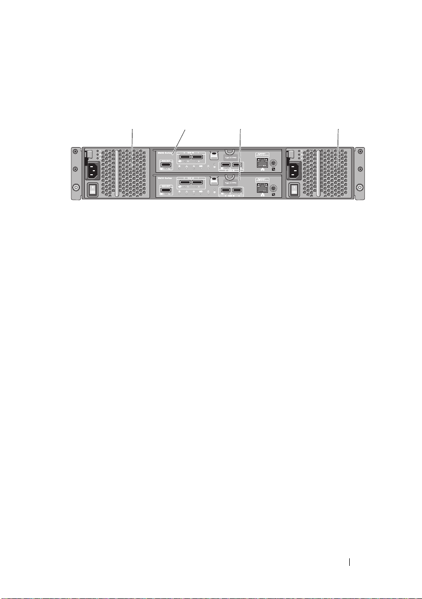
Back Panel Features and Indicators
1
2
3
4
Figure 2-4. Back-Panel Features and Indicators—Dell PowerVault MD3200 Series
1 600W Power supply/cooling fan
module
3 RAID Controller Module 1 4 600W Power supply/cooling fan
2 RAID Controller Module 0
module
Planning: About Your Storage Array 25
Page 26
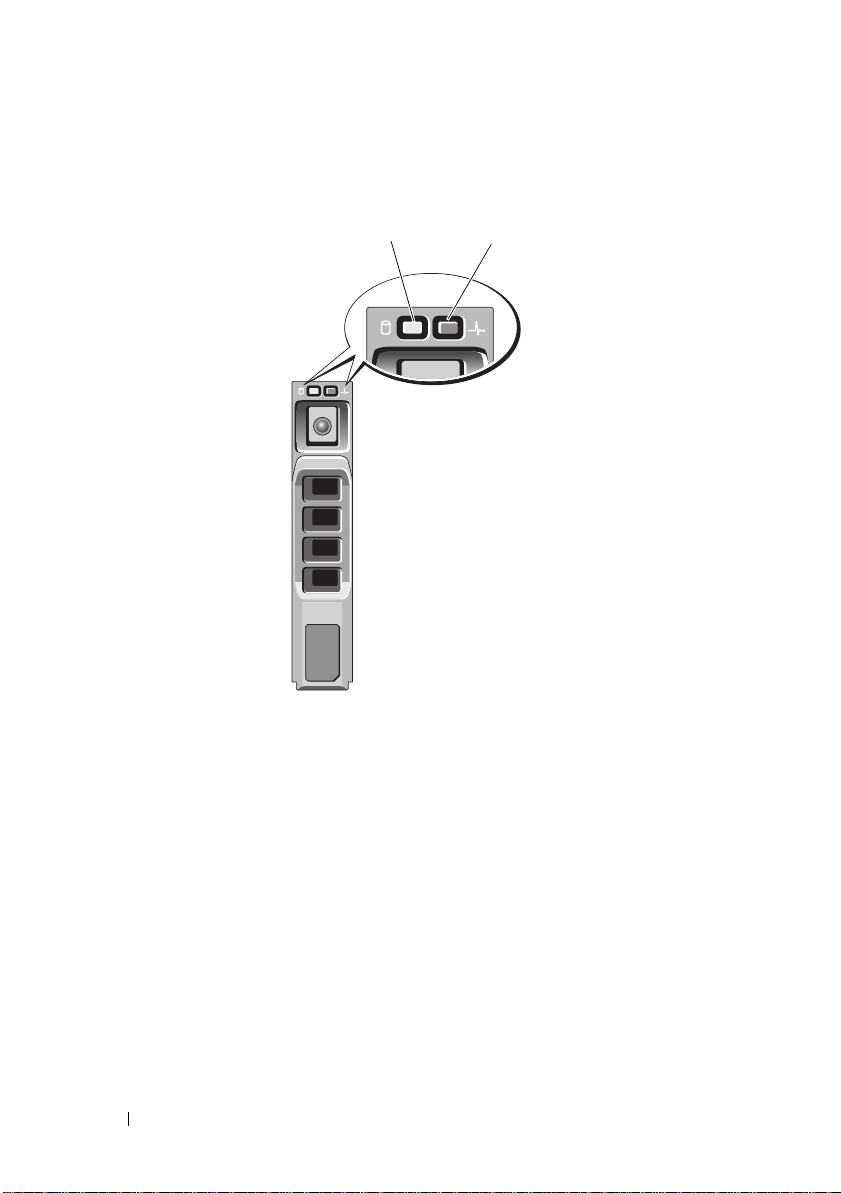
Hard-Drive Indicator Patterns
1
2
Figure 2-5. Hard Drive Indicators
1 hard-drive activity indicator (green) 2 hard-drive status indicator (green
26 Planning: About Your Storage Array
and amber)
Page 27

Drive-Status Indicator Pattern Condition
Off The physical disk is:
• not yet discovered by the host server
• has been spun down for removal
• not supported for the RAID controller
module or is not in the physical disk slot
NOTE: The drive status indicator remains
off until all hard drives are initialized
after system power is turned on.
Drives are not ready for insertion or
removal during this time.
Steady green Physical disk is online
Green flashing (On 250 ms, Off 250 ms) Physical disk is being identified
Green flashing (On 400 ms, Off 100 ms) Physical disk rebuilding
Amber flashing (On 150 ms, Off 150 ms) Physical disk failed
Flashing green, amber, and off (Green On
500 ms, Amber On 500 ms, Off 1000 ms)
Flashing green, amber, and off (Green 3
seconds, amber 3 seconds, and off 3
seconds)
Physical disk failure predicted (SMART)
Physical disk rebuild aborted
Power Supply and Cooling Fan Features
The MD3200 Series storage array includes two integrated, hot-swappable
power supply/cooling fan modules. Both modules must be installed to ensure
proper cooling. Each module contains two separate cooling fans. The system
requires at least one of the cooling fans to function to avoid overheating.
A power supply/cooling fan module can be replaced without powering down
the system. For information on removing and replacing the modules, see
"Power Supply/Cooling Fan Module" on page 204.
CAUTION: A power supply/cooling fan module can be removed from a powered-
on enclosure for a maximum period of 5 minutes. Beyond that time, the system may
automatically shut down to prevent damage.
Planning: About Your Storage Array 27
Page 28

Power Indicator Codes
1
2
3
5
4
Figure 2-6. Power Indicator Codes
Item LED Type Icon Description
1 DC power The LED lights green when the DC output
voltage is within the limit.
If this LED is off, it indicates that the DC output
voltage are not within the limit.
2 Power supply/cooling
fan fault
3 AC power The LED lights green when the AC input voltage
4 Power connector Connect the external power supply to this
5 Power switches (2) The power switch controls the power supply
The LED lights amber when the DC output
voltage is not within the limit or a fault with the
fan is detected.
If this LED is off, it indicates that no fault
condition is present.
is within the limit.
If this LED is off, it indicates either there is no
power or the AC input voltage is not within the
limit.
connector.
output to the enclosure.
28 Planning: About Your Storage Array
Page 29

3
Planning: RAID Controller Modules
RAID Controller Modules
The RAID controller modules provide high-performance, advanced virtual
disk configuration, and fault-tolerant disk subsystem management. Each
RAID controller module contains 2 GB of cache that is mirrored with the
other controller's cache for high availability and is protected by a batterypowered cache offload mechanism.
RAID controller modules provide the following data path and enclosure
management functions:
• Monitoring and controlling enclosure environment elements
(temperature, fans, power supplies, and enclosure LEDs)
• Controlling access to the physical disks
• Communicating enclosure attributes and states to the host server and
management station
Each RAID controller module has multiple SAS IN ports for host access. The
ports provide redundant host connections and support a high availability
storage environment. Various configurations can be utilized, in both single
controller (simplex) and dual controller (duplex) modes, to connect the
storage enclosure to hosts depending on specific redundancy needs.
For information on cabling, see the MD3200 and MD3220 Series storage
array’s Deployment Guide.
Planning: RAID Controller Modules 29
Page 30

RAID Controller Module Connectors and Features
12 3456 7
811121516 219 10 13 17 1814
19
20
Figure 3-1. MD3200 Series SAS RAID Controller Module
Item Component Function
1 SAS OUT port Provides SAS connection for cabling to a downchain
expansion enclosure.
2 SAS IN port 0 Provides host-to-controller SAS connection.
3 SAS IN port 1 Provides host-to-controller SAS connection.
4 SAS IN port 2 Provides host-to-controller SAS connection.
5 SAS IN port 3 Provides host-to-controller SAS connection.
6 MAC Address
label
7 Debug port Dell support only.
8SAS OUT port
link/fault LED
Provides MAC addresses of the management port.
Lights green when all four links are connected.
Lights amber when one to three links are disconnected.
Off when all links in the port are disconnected or cable is
disconnected.
30 Planning: RAID Controller Modules
Page 31

Item Component Function
9 Controller power
LED
10 SAS IN 0 port
link/fault LED
11 Controller fault
LED
12 System
identification
LED
13 SAS IN 1 port
link/fault LED
14 Cache active or
cache offload
LED
15 Battery fault Lights amber when battery backup unit or battery has
16 Password Reset
switch
17 SAS IN 2 port
link/fault LED
Lights green when controller power is on.
Off when controller is not powered.
Lights green when all four links are connected.
Lights amber when one to three links are disconnected.
Off when all links in the port are disconnected or cable is
disconnected.
Lights amber when controller fault detected.
Off when controller operating normally.
Blinks blue when system identification switch push-button
on enclosure front panel is pressed.
Lights green when all four links are connected.
Lights amber when one to three links are disconnected.
Off when all links in the port are disconnected or cable is
disconnected.
Lights green when on-board controller memory contains
data.
If AC power fails, this LED changes to indicate Cache
Offload status.
If the password reset function has successfully changed the
password, this LED flashes on and off briefly.
failed.
Off when battery backup unit is operating normally.
Activating this switch deletes the password.
Lights green when all four links are connected.
Lights amber when one to three links are disconnected.
Off when all links in the port are disconnected or cable is
disconnected.
Planning: RAID Controller Modules 31
Page 32
Item Component Function
18 SAS IN 3 port
link/fault LED
19 Management
port speed LED
20 Management
port activity LED
21 Management
port Ethernet
connector
Lights green when all four links are connected.
Lights amber when one to three links are disconnected.
Off when all links in the port are disconnected or cable is
disconnected.
Lights green when ethernet connection is operating at 1000
Mbps.
Lights amber when ethernet connection is operating at 100
Mbps.
Off when ethernet connection is operating at 10 Mbps or is
not active.
Lights green when ethernet connection is active.
Off when ethernet connection is not active.
Provides a 100/1000 Mbps Ethernet connection for out-ofband management of the enclosure.
RAID Controller Module—Additional Features
Battery Backup Unit
Each RAID controller contains a two-cell lithium ion nanopolymer battery
backup unit (BBU). It provides power to the RAID controller module in the
event of a power outage, see "RAID Controller Module Backup Battery Unit"
on page 202.
NOTE: For virtual disks, the RAID controller firmware changes the data cache
setting based on the state of the battery. If the battery is missing or does not have
sufficient charge, the controller flushes the cache and sets the write cache
attribute to Write Through for all virtual disks. When the battery is replaced, Write
Back is re-enabled.
32 Planning: RAID Controller Modules
Page 33

Storage Array Thermal Shutdown
The system automatically shuts down when system temperature exceeds the
safe threshold. The battery backup unit protects against data loss by
providing power to offload cache to non-volatile memory in the event of
power loss. It is not necessary to shut down any MD1200 Series expansion
enclosures attached to the storage array when thermal shutdown occurs.
Temperature threshold values determine the temperature at which shutdown
occurs. These thresholds cannot be changed.
Table 3-1. Shutdown Threshold Type
Threshold Temperature Exceeding Event Description
Nominal failure threshold A critical event is set
Maximum failure threshold Shutdown of the system power supplies occurs
within three minutes
Shutdown threshold Shutdown of the system power supplies occurs
within five seconds
System Password Reset
The storage array password can be reset if it is forgotten. To reset the
password, push and hold down the password reset switch for at least 5
seconds. The password is deleted. See Figure 3-1 to locate the password reset
switch.
The RAID controller module allows you to change the password. For more
about setting your password, see "Setting a Password" on page 69.
NOTE: The reset switch can be accessed by using a small object such as the tip of
a pen.
Planning: RAID Controller Modules 33
Page 34

Cache Functions and Features
Cache Mirroring
Cache mirroring function copies accepted host-write data from the primary
controller to the partner controller. This action ensures that host-write data is
safely mirrored to the partner controller before successful completion status is
returned to the host. If a controller fails, the surviving controller safely retains
all mirrored data. Cache mirroring is enabled by default.
Write-Back Cache
In Write-back Cache, write operations result in a completion signal being
sent to the host operating system as soon as the cache receives the data to be
written. The target physical disk receives the data at a more appropriate time
in order to increase controller performance. In dual-active controller
configurations with Write-back Caching enabled, the write data is always
mirrored to the cache of the second controller before completion status is
issued to the host initiator. Write-Back Cache is enabled by default unless
cache mirroring is disabled.
Write-Through Cache
In write-through cache, data is written to the physical disk before completion
status is returned to the host operating system. Write-through cache is
considered more robust than write-back cache, since a power failure is less
likely to cause loss of data. The RAID controller automatically switches to
write-through if cache mirroring is disabled or if the battery is missing or has a
fault condition.
34 Planning: RAID Controller Modules
Page 35

4
Planning: MD3200 Series Storage Array Terms and Concepts
This chapter explains terms and concepts used for configuration and
operation of MD3200 Series Storage Arrays.
Physical Disks, Virtual Disks, and Disk Groups
Physical disks in your storage array provide the physical storage capacity for
your data. Before you can begin writing data to the storage array, you must
configure the physical storage capacity into logical components, called disk
groups and virtual disks.
A disk group is a set of physical disks upon which multiple virtual disks are
created. The maximum number of physical disks supported in a disk group is
96 drives for RAID 0, RAID 1, and RAID10, and 30 drives for RAID 5 and
RAID 6. You can create disk groups from unconfigured capacity on your
storage array.
A virtual disk is a partition in a disk group that is made up of contiguous data
segments of the physical disks in the disk group. A virtual disk consists of data
segments from all physical disks in the disk group. Virtual disks and disk
groups are set up according to how you plan to organize your data. For
example, you might have one virtual disk for inventory, a second virtual disk
for financial and tax information, and so on.
All virtual disks in a disk group support the same RAID level. The storage
array supports up to 255 virtual disks (minimum size of 10 MB each) that can
be assigned to host servers. Each virtual disk is assigned a Logical Unit
Number (LUN) that is recognized by the host operating system.
Planning: MD3200 Series Storage Array Terms and Concepts 35
Page 36

Physical Disks
Only Dell™ supported 6.0-Gbps SAS physical disks are supported in the
storage array. If the storage array detects unsupported physical disks, it marks
the disk as unsupported and the physical disk becomes unavailable for all
operations.
NOTE: The MD3200 Series array must contain at least two physical disks for proper
operation. This is necessary because the physical disks are used to store
configuration information.
Physical Disk States
The storage array recognizes the physical disk states. Mode and status of
physical disks are reported in the MDSM application. Possible values for
mode and status or described in Table 4-1.
Table 4-1. RAID Controller Physical Disk States
Status Mode Description Physical Disk
Status LED
Optimal Assigned The physical disk in the indicated slot
is configured as part of a disk group.
Optimal Unassigned The physical disk in the indicated slot
is unused and available to be
configured.
Optimal Hot Spare
standby
Optimal Hot Spare in
use
Failed Assigned,
Unassigned,
Hot Spare in
use, or Hot
Spare standby
Replaced Assigned The physical disk in the indicated slot
The physical disk in the indicated slot
is configured as a hot spare.
The physical disk in the indicated slot
is in use as a hot spare within a disk
group.
The physical disk in the indicated slot
has failed because of an unrecoverable
error, an incorrect drive type or drive
size, or by its operational state being
set to failed.
has been replaced and is ready to be,
or is actively being, configured into a
disk group.
Steady Green
Steady Green
Steady Green
Steady Green
Amber flashing
(150 ms)
Green flashing
(On 400 ms, Off
100 ms)
36 Planning: MD3200 Series Storage Array Terms and Concepts
Page 37

Table 4-1. RAID Controller Physical Disk States
Status Mode Description Physical Disk
Pendin g
Failure
Offline Not applicable The physical disk has either been spun
Identify Assigned,
N/A N/A The indicated slot is empty, or the
Assigned,
Unassigned,
Hot Spare in
use, or Hot
Spare standby
Unassigned,
Hot Spare in
use, or Hot
Spare standby
A Self-Monitoring Analysis and
Reporting Technology (SMART) error
has been detected on the physical disk
in the indicated slot.
down or had a rebuild aborted by user
request.
The physical disk is being identified. Green flashing
array cannot detect the physical disk.
(continued)
Status LED
Flashing Green
(500 ms), Amber
(500 ms), and off
(1000ms)
Flashing Green
(3000 ms), Amber
(3000 ms), and
off(3000ms)
(250 ms)
If a disk drive rebuild fails because of a source drive failure or because the
drive is too small, the MDSM reports a failure of the physical disk even
though the LED state on the drive indicates the rebuild was aborted (green
for 3 seconds, amber for 3 seconds, then off for 3 seconds).
Self-Monitoring Analysis and Reporting Technology
SMART monitors the internal performance of all physical disk components to
detect faults indicating the potential for physical disk failure. SMART uses
this information to report whether failure is imminent so that a physical disk
can be replaced before failure occurs. The storage array monitors all attached
drives and notifies you when a predicted failure is reported by a physical disk.
Virtual Disks and Disk Groups
When configuring a storage array, you must:
1
Organize the physical disks into disk groups.
2
Create virtual disks within these disk groups.
Planning: MD3200 Series Storage Array Terms and Concepts 37
Page 38

3
Provide host server access.
4
Create mappings to associate the virtual disks with the host servers.
NOTE: Host server access must be created before mapping virtual disks.
Disk groups are always created in the unconfigured capacity of a storage array.
Unconfigured capacity is the available physical disk space not already
assigned in the storage array.
Virtual disks are created within the free capacity of a disk group. Free capacity
is the space in a disk group that has not been assigned to a virtual disk.
Virtual Disk States
The storage array recognizes the following virtual disk states.
Table 4-2. RAID Controller Virtual Disk States
State Description
Optimal The virtual disk contains physical disks that are all online.
Degraded The virtual disk with a redundant RAID level contains an inaccessible
physical disk. The system can still work properly, but performance may
be affected and additional disk failures may result in data loss.
Offline A virtual disk with one or more member disks in an inaccessible
(failed, missing, or offline) state. Data on the virtual disk is no longer
accessible.
Force online The storage array forces a virtual disk that is in an Offline state to an
Optimal state. If all the member physical disks are not available, the
storage array forces the virtual disk to a Degraded state. The storage
array can force a virtual disk to an Online state only when a sufficient
number of physical disks are available to support the virtual disk.
RAID Levels
RAID levels determine the way in which data is written to physical disks.
Different RAID levels provide different levels of accessibility, redundancy, and
capacity.
38 Planning: MD3200 Series Storage Array Terms and Concepts
Page 39

Using multiple physical disks has the following advantages over using a single
physical disk:
• Placing data on multiple physical disks (striping) allows input/output (I/O)
operations to occur simultaneously and improve performance.
• Storing redundant data on multiple physical disks using mirroring or parity
supports reconstruction of lost data if an error occurs, even if that error is
the failure of a physical disk.
Each RAID level provides different performance and protection. You should
select a RAID level based on the type of application, access, fault tolerance,
and data you are storing.
The storage array supports RAID levels 0, 1, 5, 6, and 10. The maximum
number of physical disks that can be used in a disk group depends on the
RAID level:
• 96 for RAID 0, 1 and 10
• 30 for RAID 5 and 6.
RAID Level Usage
To ensure best performance, you should select an optimal RAID level when
you create a system physical disk. The optimal RAID level for your disk array
depends on:
• Number of physical disks in the disk array
• Capacity of the physical disks in the disk array
• Need for redundant access to the data (fault tolerance)
• Disk performance requirements
RAID 0
RAID 0 uses disk striping to provide high data throughput, especially for large
files in an environment that requires no data redundancy. RAID 0 breaks the
data down into segments and writes each segment to a separate physical disk.
I/O performance is greatly improved by spreading the I/O load across many
physical disks. Although it offers the best performance of any RAID level,
RAID 0 lacks data redundancy. Choose this option only for non-critical data,
because failure of one physical disk results in the loss of all data. Examples of
RAID 0 applications include video editing, image editing, prepress
applications, or any application requiring high bandwidth.
Planning: MD3200 Series Storage Array Terms and Concepts 39
Page 40

RAID 1
RAID 1 uses disk mirroring so that data written to one physical disk is
simultaneously written to another physical disk. This RAID level offers fast
performance and the best data availability, but also the highest disk overhead.
RAID 1 is recommended for small databases or other applications that do not
require large capacity for example accounting, payroll, or financial
applications. RAID 1 provides full data redundancy.
RAID 5
RAID 5 uses parity and striping data across all physical disks (distributed
parity) to provide high data throughput and data redundancy, especially for
small random access. RAID 5 is a versatile RAID level and is suited for multiuser environments where typical I/O size is small and there is a high
proportion of read activity such as file, application, database, web, e-mail,
news, and intranet servers.
RAID 6
RAID 6 is similar to RAID 5 but provides an additional parity disk for better
redundancy. RAID 6 is the most versatile RAID level and is suited for multiuser environments where typical I/O size is small and there is a high
proportion of read activity. RAID 6 is recommended when large size physical
disks are used or large number of physical disks are used in a disk group.
RAID 10
RAID 10, a combination of RAID 1 and RAID 0, uses disk striping across
mirrored disks. It provides high data throughput and complete data
redundancy. Utilizing an even number of physical disks (four or more) creates
a RAID level 10 disk group and/or virtual disk. Because RAID levels 1 and 10
use disk mirroring, half of the capacity of the physical disks is utilized for
mirroring. This leaves the remaining half of the physical disk capacity for
actual storage. RAID 10 is automatically used when a RAID level of 1 is
chosen with four or more physical disks. RAID 10 works well for mediumsized databases or any environment that requires high performance and fault
tolerance and moderate-to-medium capacity.
40 Planning: MD3200 Series Storage Array Terms and Concepts
Page 41

Segment Size
Disk striping enables data to be written across multiple physical disks. Disk
striping enhances performance because striped disks are accessed
simultaneously.
The segment size or stripe element size specifies the size of data in a stripe
written to a single disk. The MD3200 Series array supports stripe element
sizes of 8, 16, 32, 64, 128, 256, and 512 KB. The default stripe element size is
128 KB.
Stripe width, or depth, refers to the number of disks involved in an array
where striping is implemented. For example, a four-disk group with disk
striping has a stripe width of four.
NOTE: Although disk striping delivers excellent performance, striping alone does
not provide data redundancy.
Virtual Disk Operations
Virtual Disk Initialization
Every virtual disk must be initialized. Initialization can be done in the
foreground or the background. A maximum of four virtual disks can be
initialized concurrently on each RAID controller module.
Background Initialization
The storage array executes a background initialization when the virtual disk is
created to establish parity, while allowing full host server access to the virtual
disks. Background initialization does not run on RAID 0 virtual disks. The
background initialization rate is controlled by MDSM. To change the rate of
background initialization, you must stop any existing background
initialization. The rate change is implemented when the background
initialization restarts automatically.
Foreground Initialization
The storage array supports foreground initialization for virtual disks. All
access to the virtual disk is blocked during foreground initialization. During
foreground initialization, zeros (0x00) are written to every sector of the virtual
disk. The virtual disk is available after foreground initialization is completed.
Planning: MD3200 Series Storage Array Terms and Concepts 41
Page 42

Consistency Check
A consistency check verifies the correctness of data in a redundant array
(RAID levels 1, 5, 6, and 10). For example, in a system with parity, checking
consistency involves computing the data on one physical disk and comparing
the results to the contents of the parity physical disk.
A consistency check is similar to a background initialization. The difference is
that background initialization cannot be started or stopped manually, while
consistency check can.
NOTE: It is recommended that you run data consistency checks on a redundant
array at least once a month. This allows detection and automatic replacement of
unreadable sectors. Finding an unreadable sector during a rebuild of a failed
physical disk is a serious problem, because the system does not have the
redundancy to recover the data.
Media Verification
Another background task performed by the storage array is media verification
of all configured physical disks in a disk group. The storage array uses the
Read operation to perform verification on the space configured in virtual
disks and the space reserved for the metadata.
Cycle Time
The media verification operation runs only on selected disk groups,
independent of other disk groups. Cycle time is the time taken to complete
verification of the metadata region of the disk group and all virtual disks in
the disk group for which media verification is configured. The next cycle for a
disk group starts automatically when the current cycle completes. You can set
the cycle time for a media verification operation between 1 and 30 days. The
storage controller throttles the media verification I/O accesses to disks based
on the cycle time.
The storage array tracks the cycle for each disk group independent of other
disk groups on the controller and creates a checkpoint. If the media
verification operation on a disk group is preempted or blocked by another
operation on the disk group, the storage array resumes after the current cycle.
If the media verification process on a disk group is stopped due to a RAID
controller module restart, the storage array resumes the process from the last
checkpoint.
42 Planning: MD3200 Series Storage Array Terms and Concepts
Page 43

Virtual Disk Operations Limit
The maximum number of active, concurrent virtual disk processes per RAID
controller module installed in the storage array is four. This limit is applied to
the following virtual disk processes:
• Background initialization
• Foreground initialization
• Consistency check
•Rebuild
•Copy back.
If a redundant RAID controller module fails with existing virtual disk
processes, the processes on the failed controller are transferred to the peer
controller. A transferred process is placed in a suspended state if there are four
active processes on the peer controller. The suspended processes are resumed
on the peer controller when the number of active processes falls below four.
Disk Group Operations
RAID Level Migration
You can migrate from one RAID level to another depending on your
requirements. For example, fault-tolerant characteristics can be added to a
stripe set (RAID 0) by converting it to a RAID 5 set. MDSM provides
information about RAID attributes to assist you in selecting the appropriate
RAID level. You can perform a RAID level migration while the system is still
running and without rebooting, which maintains data availability.
Segment Size Migration
Segment size refers to the amount of data (in kilobytes) that the storage array
writes on a single physical disk in a virtual disk before writing data on the next
physical disk. Valid values for the segment size are 8, 16, 32, 64, 128, 256, and
512 KB.
Planning: MD3200 Series Storage Array Terms and Concepts 43
Page 44

Dynamic segment size migration enables the segment size of a given virtual
disk to be changed. A default segment size is set when the virtual disk is
created, based on such factors as the RAID level and expected usage. You can
change the default value (128 KB) if segment size usage does not match your
needs.
When considering a segment-size change, two scenarios illustrate different
approaches to the limitations:
• If I/O activity stretches beyond the segment size, you can increase it to
reduce the number of disks required for a single I/O. Using a single physical
disk for a single request frees disks to service other requests, especially
when you have multiple users accessing a database or storage environment.
• If you use the virtual disk in a single-user, large I/O environment (such as
for multimedia application storage), performance can be optimized when
a single I/O request is serviced with a single data stripe (the segment size
multiplied by the number of physical disks in the disk group used for data
storage). In this case, multiple disks are used for the same request, but
each disk is only accessed once.
Virtual Disk Capacity Expansion
When you configure a virtual disk, you select a capacity based on the amount
of data you expect to store. However, you may need to increase the virtual disk
capacity for a standard virtual disk by adding free capacity to the disk group.
This creates more unused space for new virtual disks or to expand existing
virtual disks.
Disk Group Expansion
Because the storage array supports hot pluggable physical disks, you can add
two physical disks at a time for each disk group while the storage array
remains online. Data remains accessible on virtual disk groups, virtual disks,
and physical disks throughout the operation. The data and increased unused
free space are dynamically redistributed across the disk group. RAID
characteristics are also reapplied to the disk group as a whole.
44 Planning: MD3200 Series Storage Array Terms and Concepts
Page 45

Disk Group Defragmentation
Defragmenting consolidates the free capacity in the disk group into one
contiguous area. Defragmentation does not change the way in which the data
is stored on the virtual disks.
Disk Group Operations Limit
The maximum number of active, concurrent disk group processes per
installed RAID controller module is one. This limit is applied to the following
disk group processes:
• Virtual disk RAID level migration
• Segment size migration
• Virtual disk capacity expansion
• Disk group expansion
• Disk group defragmentation.
If a redundant RAID controller module fails with an existing disk group
process, the process on the failed controller is transferred to the peer
controller. A transferred process is placed in a suspended state if there is an
active disk group process on the peer controller. The suspended processes are
resumed when the active process on the peer controller completes or is
stopped.
NOTE: If you try to start a disk group process on a controller that does not have an
existing active process, the start attempt fails if the first virtual disk in the disk group
is owned by the other controller and there is an active process on the other
controller.
RAID Background Operations Priority
The storage array supports a common configurable priority for the following
RAID operations:
• Background initialization
•Rebuild
•Copy back
• Virtual disk capacity expansion
• Raid level migration
Planning: MD3200 Series Storage Array Terms and Concepts 45
Page 46

• Segment size migration
• Disk group expansion
• Disk group defragmentation.
The priority of each of these operations can be changed to address
performance requirements of the environment in which the operations are to
be executed.
NOTE: Setting a high priority level impacts storage array performance. It is not
advisable to set priority levels at the maximum level. Priority should also be
assessed in terms of impact to host server access and time to complete an
operation. For example, the longer a rebuild of a degraded virtual disk takes, the
greater the risk for potential secondary disk failure.
Virtual Disk Migration and Disk Roaming
Virtual disk migration is moving a virtual disk or a hot spare from one array to
another by detaching the physical disks and re-attaching them to the new
array. Disk roaming is moving a physical disk from one slot to another on the
same array.
Disk Migration
You can move virtual disks from one array to another without taking the
target array offline. However, the disk group being migrated must be offline
prior to performing the disk migration. If the disk group is not offline prior to
migration, the source array holding the physical and virtual disks within the
disk group marks them as missing. However, the disk groups themselves
migrate to the target array.
An array can import a virtual disk only if it is in an optimal state. You can
move virtual disks that are part of a disk group only if all members of the disk
group are being migrated. The virtual disks automatically become available
after the target array has finished importing all the disks in the disk group.
When you migrate a physical disk or a disk group from one MD3200 array to
another, the MD3200 array you migrate to, recognizes any data structures
and/or metadata you had in place on the migrating MD3200 array. However, if
you are migrating from any device other than a MD3200 Series Storage Array,
46 Planning: MD3200 Series Storage Array Terms and Concepts
Page 47
the MD3200 array does not recognize the migrating metadata and that data is
lost. In this case, the MD3200 initializes the physical disks and mark them as
unconfigured capacity.
NOTE: Only disk groups and associated virtual disks with all member physical disks
present can be migrated from one storage array to another. it is recommended that
you only migrate disk groups that have all their associated member virtual disks in
an optimal state.
NOTE: The number of physical disks and virtual disks that a storage array supports
limits the scope of the migration.
Use either of the following methods to move disk groups and virtual disks:
• Hot virtual disk migration—Disk migration with the destination storage
array power turned on.
• Cold virtual disk migration—Disk migration with the destination storage
array power turned off.
NOTE: To ensure that the migrating disk groups and virtual disks are correctly
recognized when the target storage array has an existing physical disk, use hot
virtual disk migration.
When attempting virtual disk migration, follow these recommendations:
• Moving physical disks to the destination array for migration—When
inserting drives into the destination storage array during hot virtual disk
migration, wait for the inserted physical disk to be displayed in MDSM
before inserting the next physical disk.
WARNING: Without the delay between drive insertions, the storage array
can become unstable and manageability is temporarily lost.
• Migrating virtual disks from multiple storage arrays into a single storage
array—When migrating virtual disks from multiple or different storage
arrays into a single destination storage array, move all of the physical disks
from the same storage array as a set into the new destination storage array.
Ensure that all of the physical disks from a storage array are migrated to
the destination storage array before starting migration from the next
storage array.
NOTE: If the drive modules are not moved as a set to the destination storage
array, the newly relocated disk groups might not be accessible.
Planning: MD3200 Series Storage Array Terms and Concepts 47
Page 48
• Migrating virtual disks to a storage array with no existing physical disks—
Turn off the destination storage array, when migrating disk groups or a
complete set of physical disks from a storage array to another storage array
that has no existing physical disks. After the destination storage array has
been turned on and has successfully recognized the newly migrated
physical disks, migration operations can continue.
NOTE: Disk groups from multiple storage arrays should not be migrated at the
same time to a storage array that has no existing physical disks.
• Enabling premium features before migration—Before migrating disk
groups and virtual disks, enable the required premium features on the
destination storage array. If a disk group is migrated from a MD3200
storage array that has a premium feature enabled and the destination array
does not have this feature enabled, an
can be generated.
Out of Compliance
error message
Disk Roaming
You can move physical disks within an array. The RAID controller module
automatically recognizes the relocated physical disks and logically places
them in the proper virtual disks that are part of the disk group. Disk roaming
is permitted when the RAID controller module is either online or powered
off.
NOTE: The disk group must be exported before moving the physical disks.
Advanced Features
The RAID enclosure supports several advanced features:
• Virtual Disk Snapshots
•Virtual Disk Copy
• High Performance Tier
NOTE: Virtual Disk Snapshot, Virtual Disk Copy, and High Performance Tier are
premium features that must be activated separately. If you have purchased these
features, an activation card is supplied that contains instructions for enabling this
functionality.
48 Planning: MD3200 Series Storage Array Terms and Concepts
Page 49

Host Server-to-Virtual Disk Mapping
The host server attached to a storage array accesses various virtual disks on
the storage array through its host ports. Specific virtual disk-to-LUN
mappings to an individual host server can be defined. In addition, the host
server can be part of a host group that shares access to one or more virtual
disks.
You can manually configure a host server-to-virtual disk mapping. When you
configure host server-to-virtual disk mapping, consider these guidelines:
• You can define one host server-to-virtual disk mapping for each virtual disk
in the storage array.
• Host server-to-virtual disk mappings are shared between RAID controller
modules in the storage array.
• A unique LUN must be used by a host group or host server to access a
virtual disk.
• Not every operating system has the same number of LUNs available for
use.
Host Types
A host server is a server that accesses a storage array. Host servers are mapped
to the virtual disks. Host servers have the following attributes:
• Host name—A name that uniquely identifies the host server.
• Host group (used in Cluster solutions only)—Two or more host servers
associated together to share access to the same virtual disks.
This host group is a logical entity you can create in MDSM. All host servers
in a host group must be running the same operating system.
• Host type—The operating system running on the host server.
Snapshot Virtual Disks
A snapshot is a point-in-time image of a virtual disk. The snapshot provides
an image of the virtual disk at the time the snapshot was created. You create a
snapshot so that an application (for example, a backup application) can
access the snapshot and read the data while the source virtual disk remains
Planning: MD3200 Series Storage Array Terms and Concepts 49
Page 50

online and user-accessible. When the backup is completed, the snapshot
virtual disk is no longer needed. You can create up to four snapshots per
virtual disk.
Snapshots are used to recover previous versions of files that have changed
since the snapshot was taken. Snapshots are implemented using a copy-onwrite algorithm, which makes a backup copy of data the instant an error
occurs. Data on a virtual disk is copied to the snapshot repository before it is
modified. Snapshots are instantaneous and take up less overhead than a full
physical copy process.
Snapshot Repository Virtual Disk
When you create a snapshot virtual disk, it automatically creates a snapshot
repository virtual disk. A snapshot repository is a virtual disk created in the
storage array as a resource for a snapshot virtual disk. A snapshot repository
virtual disk contains snapshot virtual disk metadata and copy-on-write data
for a particular snapshot virtual disk. The repository supports one snapshot
only.
You cannot select a snapshot repository virtual disk as a source virtual disk or
as a target virtual disk in a virtual disk copy. If you select a Snapshot source
virtual disk as the target virtual disk of a virtual disk copy, you must disable all
snapshot virtual disks associated with the source virtual disk.
CAUTION: Before using the Snapshot Virtual Disks Premium Feature in a
Windows
cluster node that owns the source virtual disk. This ensures that the cluster nodes
correctly recognize the snapshot virtual disk.
®
Clustered configuration, you must map the snapshot virtual disk to the
Mapping the snapshot virtual disk to the node that does not own the source
virtual disk before the snapshot enabling process is completed can result in
the operating system incorrectly identifying the snapshot virtual disk. This
can result in data loss or an inaccessible snapshot.
For details on mapping the snapshot virtual disk to the secondary node, refer
to the Dell™ PowerVault™ MD3200 and MD3220 Storage Arrays With
Microsoft® Windows Server® Failover Clusters on support.dell.com/manuals.
50 Planning: MD3200 Series Storage Array Terms and Concepts
Page 51

Virtual Disk Copy
Virtual disk copy is a premium feature you can use to:
•Back up data
• Copy data from disk groups that use smaller-capacity physical disks to disk
groups using greater capacity physical disks
• Restore snapshot virtual disk data to the source virtual disk.
Virtual disk copy generates a full copy of data from the source virtual disk to
the target virtual disk in a storage array.
Source Virtual Disk
When you create a virtual disk copy, a copy pair consisting of a source virtual
disk and a target virtual disk is created on the same storage array. When a
virtual disk copy is started, data from the source virtual disk is copied
completely to the target virtual disk.
Target Virtual Disk
When you start a virtual disk copy, the target virtual disk maintains a copy of
the data from the source virtual disk. You can choose whether to use an
existing virtual disk or create a new virtual disk as the target virtual disk. If
you choose an existing virtual disk as the target, all data on the target is
overwritten. A target virtual disk can be a standard virtual disk or the source
virtual disk of a failed or disabled snapshot virtual disk.
NOTE: The target virtual disk capacity must be equal to or greater than the source
virtual disk capacity.
When you begin the disk copy process, you must define the rate at which the
copy is completed. Giving the copy process top priority slightly impacts I/O
performance, while giving it lowest priority makes the copy process longer to
complete. You can modify the copy priority while the disk copy is in progress.
For more information, see the online help topics.
Virtual Disk Recovery
You can use the Edit host server-to-virtual disk mappings feature to recover
data from the backup virtual disk. This functionality enables you to unmap
the original source virtual disk from its host server, then map the backup
virtual disk to the same host server.
Planning: MD3200 Series Storage Array Terms and Concepts 51
Page 52

Ensure that you record the LUN used to provide access to the source virtual
disk. You need this information when you define a host server-to-virtual disk
mapping for the target (backup) virtual disk. Also, be sure to stop all I/O
activity to the source virtual disk before beginning the virtual disk recovery
procedure.
Using Snapshot and Disk Copy Together
You can use the Snapshot Virtual Disk and Virtual Disk Copy premium
features together to back up data on the same storage array, or to restore the
data on the snapshot virtual disk to its original source virtual disk.
You can copy data from a virtual disk in one of two ways:
• By taking a point-in-time snapshot of the data
• By copying the data to another virtual disk using a virtual disk copy
You can select a snapshot virtual disk as the source virtual disk for a virtual
disk copy. This configuration is one of the best ways you can apply the
snapshot virtual disk feature, since it enables complete backups without any
impact to the storage array I/O.
You cannot use a snapshot repository virtual disk as a source virtual disk or as
a target virtual disk in a virtual disk copy. If you select the source virtual disk
as the target virtual disk of a virtual disk copy, you must disable all snapshot
virtual disks associated with the source virtual disk.
Multi-Path Software
Multi-path software (also referred to as the failover driver) is software resident
on the host server that provides management of the redundant data path
between the host server and the storage array.
The multi-path software identifies the existence of multiple paths to a virtual
disk and establishes a preferred path to that disk. If any component in the
preferred path fails, the multi-path software automatically re-routes I/O
requests to the alternate path so that the storage array continues to operate
without interruption.
NOTE: Multi-path software available on the MD3200 series resource media.
52 Planning: MD3200 Series Storage Array Terms and Concepts
Page 53

Preferred and Alternate Controllers and Paths
A preferred controller is a RAID controller module designated as the owner of
a virtual disk or disk group. The preferred controller is automatically selected
by MDSM when a virtual disk is created. You can change the preferred RAID
controller module owner of a virtual disk after it is created. If a host is only
connected to only one RAID controller module, the preferred owner must
manually be assigned to the RAID controller module the host can access.
Ownership of a virtual disk is moved from the preferred controller to the
secondary controller (also called the alternate controller) when the preferred
controller is:
• Physically removed
• Updating firmware
• Involved in an event that caused failover to the alternate controller
Paths used by the preferred RAID controller module to access either the disks
or the host server are called the preferred paths; redundant paths are called
the alternate paths. If a failure causes the preferred path to become
inaccessible, the storage array automatically uses the alternate path to access
data, when this occurs the enclosure status LED blinks amber.
Virtual Disk Ownership
MDSM can be used to automatically build and view virtual disks. It uses
optimal settings to stripe the disk group. Virtual disks are assigned to
alternating RAID controller modules when they are created. This default
assignation provides a simple means for load balancing the workload of the
RAID controller modules.
Ownership can later be modified to balance workload according to actual
usage. If virtual disk ownership is not manually balanced, it is possible for one
controller to have the majority of the work, while the other controller is idle.
Limit the number of virtual disks in a disk group. If multiple virtual disks are
in a disk group, consider:
• The impact each virtual disk has on other virtual disks in the same disk
group.
• The patterns of usage for each virtual disk.
• Different virtual disks have higher usage at different times of day.
Planning: MD3200 Series Storage Array Terms and Concepts 53
Page 54

Load Balancing
A load balance policy is used to determine which path is used to process I/O.
Multiple options for setting the load balance policies lets you optimize I/O
performance when mixed host interfaces are configured.
You can choose one of these load balance policies to optimize I/O
performance:
• Round robin with subset—The round robin with subset I/O load balance
policy routes I/O requests, in rotation, to each available data path to the
RAID controller module that owns the virtual disks. This policy treats all
paths to the RAID controller module that owns the virtual disk equally for
I/O activity. Paths to the secondary RAID controller module are ignored
until ownership changes. The basic assumption for the round-robin policy
is that the data paths are equal. With mixed host support, the data paths
might have different bandwidths or different data transfer speeds.
• Least queue depth with subset—The least queue depth with subset policy
is also known as the least I/Os or least requests policy. This policy routes
the next I/O request to a data path that has the least outstanding I/O
requests queued. For this policy, an I/O request is simply a command in
the queue. The type of command or the number of blocks that are
associated with the command are not considered.The least queue depth
with subset policy treats large block requests and small block requests
equally. The data path selected is one of the paths in the path group of the
RAID controller module that owns the virtual disk.
• Least path weight with subset (Windows operating systems only)—The
least queue depth with subset policy is also known as the least I/Os or least
requests policy. This policy routes the next I/O request to a data path that
has the least outstanding I/O requests queued. For this policy, an I/O
request is simply a command in the queue. The type of command or the
number of blocks that are associated with the command are not
considered. The least queue depth with subset policy treats large block
requests and small block requests equally. The data path selected is one of
the paths in the path group of the RAID controller module that owns the
virtual disk.
54 Planning: MD3200 Series Storage Array Terms and Concepts
Page 55
Monitoring MD3200 Series System Performance
You can use the Performance Monitor to select virtual disks and RAID
controller modules to monitor or to change the polling interval. Keep these
guidelines in mind when using the Performance Monitor:
• The Performance Monitor does not dynamically update its display if any
configuration changes occur while the window is open. You must close the
Performance Monitor window and reopen it for the changes to appear.
• Using the Performance Monitor to retrieve performance data can affect
the normal storage array performance depending on the polling interval
that you set.
• If the storage array you are monitoring begins in or transitions to an
unresponsive state, an informational dialog appears. The dialog informs
you that the Performance Monitor cannot poll the storage array for
performance data.
To monitor the performance of the arrays:
1
Open MDSM and select the appropriate storage array.
2
Open the Array Management Window (AMW) for the selected storage
array
3
In the AMW, select
4
Click
Settings
a
Select the items that you want to monitor. You can monitor:
• RAID controller modules
•Virtual disks
• Storage array totals
Storage Array Monitor Performance
.
.
NOTE: By default, all items are selected.
b
In
Polling interval
performance statistics.
NOTE: For an accurate elapsed time, do not use the Set RAID Controller
Module Clocks option while using the Performance Monitor.
Each time the polling interval elapses, the Performance Monitor queries
the storage array again and updates the statistics in the table.
Planning: MD3200 Series Storage Array Terms and Concepts 55
, select how often you want to update the
Page 56

5
Click
Start
.
Values appear for the selected storage arrays in the Performance Monitor
data table. The table is updated at the interval specified in the Polling
Interval setting.
6
Click
7
8
Click
Click
Update
Stop
Save As
to force an immediate poll of the storage array.
to stop monitoring the storage array.
on the Performance Monitor main dialog to save the
currently displayed performance statistics.
9
Select an appropriate directory.
10
Type a file name in the
NOTE: The .perf extension is the default.
11
Select a file type from the Files of type list.
•Use the
Report format
File name
text box.
(ASCII text) file type if you want to save the
data to a report form for viewing or printing.
•Use the
Comma Delimited Format
file type if you want to save the
data in a form that can be imported into a commercial spreadsheet
application for further analysis. Most leading commercial spreadsheet
applications recognize a comma delimiter. These applications use the
delimiter to import the data into spreadsheet cells.
12
Click
Save
.
The Performance Monitor data provides information about how your storage
array is performing. The data is presented in eight columns, which are
described in this table. Use this data to make performance tuning decisions
for your storage array.
Table 4-3. Performance Monitor Table Description
Column Headings Description
Devices Controller, virtual disk or storage array total.
Total IOs Cumulative IO’s per second from last start time.
Read Percentage Percentage of cumulative IO’s that are READs.
Cache Hit Percentage Percentage of cumulative IO’s that are in-cache.
56 Planning: MD3200 Series Storage Array Terms and Concepts
Page 57

Table 4-3. Performance Monitor Table Description
Column Headings Description
Current KB/second Snapshot of throughput value per second (1KB = 1024
bytes).
Maximum KB/second Maximum recorded throughput value from last start time.
Current IO/second Snapshot of IO’s per second (IOP = Input/output per
second or one completed I/O transaction).
Maximum IO/second Maximum recorded IOP from last start time.
For more information, see the online help topics.
Planning: MD3200 Series Storage Array Terms and Concepts 57
Page 58

58 Planning: MD3200 Series Storage Array Terms and Concepts
Page 59

5
Configuration: Overview
Dell™ PowerVault™ Modular Disk Storage Manager (MDSM) online help
contains information on the how to use the MDSM application to perform
the configuration and management tasks described in this document. You can
access online help by selecting Help located at the top right corner of MDSM
interface. See the MD3200 and MD3220 Storage Array’s Deployment Guide
Deployment Guide for information on installing the MDSM.
NOTE: MDSM supports MD3000 and MD3200 storage arrays and can automatically
detect both these storage arrays.
User Interface
The Storage Manager screen is divided into two primary windows:
• Enterprise Management Window (EMW)—The EMW provides highlevel management of the storage arrays. You can launch the Array
Management Window from the EMW.
• Array Management Window (AMW)—The AMW provides management
functions for a single storage array. You can launch more than one AMW at
the same time to manage different storage arrays.
The EMW and the AMW consist of the following:
• The title bar at the top of the window shows the name of the application.
• Beneath the title bar, is the menu bar. You can select menu options from
the menu bar to perform tasks on a storage array.
• Beneath the menu bar, is the toolbar. You can select options in the toolbar
to perform tasks on a storage array.
• Beneath the toolbar, are the tabs. Tabs are used to group the tasks that you
can perform on a storage array.
• Beneath the tabs, is the status bar. The status bar shows status messages
and status icons related to the storage array.
NOTE: By default, the toolbar and status bar do not appear. To view the toolbar or
the status bar, select ViewToolbar or View Status Bar, respectively.
Configuration: Overview 59
Page 60

Enterprise Management Window
The EMW provides high-level management of storage arrays. When you start
MDSM, the EMW opens. The EMW has these tabs:
•
Devices
•
Setup
storage arrays and configuring alerts.
The Devices tab has a Tree view on the left side of the window that shows
discovered storage arrays, unidentified storage arrays, and the status
conditions for the storage arrays. Discovered storage arrays are managed by
MDSM. Unidentified storage arrays are available to MDSM but not
configured for management. The right side of the Devices tab has a Table
view that shows detailed information for each storage array.
In the EMW, you can:
• Discover hosts and managed storage arrays on the local sub-network.
• Manually add and remove hosts and storage arrays.
• Locate the storage arrays.
• Name or Rename discovered storage arrays.
• Add storage array comments to the Table view.
• Sort rows in the Table view according to different criteria.
• Store your EMW view preferences and configuration data in local
configuration files. The next time you open the EMW, data from the local
configuration files is used to show customized view and preferences.
• Monitor the status of managed storage arrays and indicate status using
appropriate icons.
• Add or remove management connections.
• Configure alert notifications for all selected storage arrays through e-mail
or SNMP traps.
• Report critical events to the configured alert destinations.
• Launch the AMW for a selected storage array.
• Run a script to perform batch management tasks on specific storage arrays.
• Import the operating system theme settings into the MDSM.
• Upgrade firmware on multiple storage arrays concurrently.
tab—Provides information about the storage arrays.
tab—Presents the initial setup tasks that guide you through adding
60 Configuration: Overview
Page 61

Inheriting the System Settings
Use the Inherit System Settings option to import the operating system theme
settings into the MDSM. Importing system theme settings affects such
features as font type, font size, color, and contrast in the MDSM.
1
Open the Inherit System Settings window in one of these ways:
• Select
• Select the Setup tab, and click
2
Select
3
Click OK.
Tools
Inherit System Settings
.
Inherit System Settings
Inherit system settings for color and font
.
.
Array Management Window
You can launch the AMW from the EMW. The AMW provides management
functions for a single storage array. You can have multiple AMWs open
simultaneously to manage different storage arrays.
To launch the AMW:
1
In the
EMW
, on the
The context menu for the selected storage is displayed.
2
In the context menu, select
The AMW for the selected storage is displayed.
The AMW has the following tabs:
• Summary tab—You can view the following information about the storage
array:
• Status
• Hardware components
• Capacity
•Hosts and Mappings
• Storage partitions
• Disk groups and virtual disks
• Logical tab—You can view the organization of the storage array by virtual
disks, disk groups, free capacity nodes, and any unconfigured capacity for
the storage array.
Devices
tab, double click on the relevant storage array.
Manage Storage Array.
Configuration: Overview 61
Page 62

• Physical tab—You can view the organization of the storage array by RAID
controller modules, physical disks, and other hardware components.
• Mappings tab—You can define the hosts, host groups, and host ports. You
can change the mappings to grant virtual disk access to host groups and
hosts and create storage partitions.
• Setup tab—You can complete the initial setup tasks to configure the
storage array.
• Support—You can complete common support tasks like downloading
RAID controller module firmware, viewing the online help, and so on.
In the AMW, you can:
• Provide storage array options, for example, renaming a storage array,
changing a password, or enabling a background media scan.
• Provide the ability to configure virtual disks from the storage array
capacity, define hosts and host groups, and grant host or host group access
to sets of virtual disks called storage partitions.
• Monitor the health of storage array components and report detailed status
using applicable icons.
• Provide applicable recovery procedures for a failed logical component or a
failed hardware component.
• Present a view of the Event Log for the storage array.
• Present profile information about hardware components, such as RAID
controller modules and physical disks.
• Provide RAID controller module management options, such as changing
ownership of virtual disks or placing a RAID controller module online or
offline.
• Provide physical disk management options, such as assignment of hot
spares and locating the physical disk.
• Monitor storage array performance.
62 Configuration: Overview
Page 63

6
Configuration: About Your Storage Array
Out-of-Band and In-Band Management
You can manage a storage array in two ways:
• Out-of-band management
• In-band management
Out-of-Band Management
Using the out-of-band management method, data is separate from
commands and events. Data travels through the host-to-controller interface,
while commands and events travel through the management port Ethernet
cables.
This management method lets you configure the maximum number of
virtual disks that are supported by your operating system and host adapters. A
maximum of eight storage management stations can concurrently monitor an
out-of-band managed storage array. This limit does not apply to systems that
manage the storage array through the in-band management method.
When you use out-of-band management, you must set the network
configuration for each RAID controller module’s management Ethernet port.
This includes the Internet Protocol (IP) address, subnetwork mask (subnet
mask), and gateway. If you are using a Dynamic Host Configuration Protocol
(DHCP) server, you can enable automatic network configuration, but if you
are not using a DHCP server, you must enter the network configuration
manually.
NOTE: RAID controller module network configurations can be assigned using a
DHCP server (the default setting). However, if a DHCP server is not available for 150
seconds, the RAID controller modules assign static IP addresses. The addresses
assigned are 192.168.128.101 for controller 0 and 192.168.128.102 for controller 1.
Configuration: About Your Storage Array 63
Page 64
In-Band Management
Using in-band management, commands, events, and data travel through the
host-to-controller interface. Unlike out-of-band management, commands and
events are mixed with data.
NOTE: For detailed information on setting up in-band and out-of-band management
see the
Deployment Guide
.
When you add storage arrays by using this management method, you need to
specify only the host name or IP address of the host. After you add the
specific host name or IP address, the host-agent software automatically
detects any storage arrays that are connected to that host.
CAUTION: Some operating systems can be used only as storage management
stations. For more information about the operating system that you are using, refer
to the MD PowerVault Support Matrix at support.dell.com/manuals.
For more information, see the PowerVault Modular Disk Storage Manager
online help topics.
Access Virtual Disk
Each RAID controller module in an MD3200 Series storage array maintains a
special virtual disk, called the access virtual disk. The host-agent software uses
the access virtual disk to communicate management requests and event
information between the storage management station and the RAID
controller module in an in-band–managed storage array. The access virtual
disk is not available for application data storage. The default LUN is 31.
Storage Arrays
You must add the storage arrays to MDSM before you can setup the storage
array for optimal use.
Adding Storage Arrays
You can add storage arrays only in the EMW. You can:
• Automatically discover storage arrays
• Manually add storage arrays
NOTE: Verify that your host or management station network configuration—
including station IP address, subnet mask, and default gateway—is correct before
adding a new storage array using the Automatic option.
64 Configuration: About Your Storage Array
Page 65
NOTE: For Linux, set the default gateway so that broadcast packets are sent to
255.255.255.0. For Red Hat® Enterprise Linux®, if no gateway exists on the network,
set the default gateway to the IP address of the NIC.
NOTE: MDSM uses TCP/UDP port 2463 for communication to the MD Storage
Array.
Automatic Discovery of Storage Arrays
The Automatic Discovery process sends out a broadcast message across the
local subnetwork (subnet) and adds any storage array that responds to the
message. The Automatic Discovery process finds both in-band and out-ofband storage arrays.
NOTE: The Automatic Discovery option and the Re-scan Hosts option in the
Enterprise Management Window provide automatic methods for discovering
managed storage arrays.
Manual Addition of a Storage Array
Use Manual Addition if the storage array resides outside of the local subnet.
This process requires specific identification information to manually add a
storage array.
To add a storage array that uses out-of-band management, specify the host
name or management port IP address of each controller in the storage array.
Before using this option, verify that the applicable network configuration
tasks have been performed.
To add an in-band storage array, add the host through which the storage array
is attached to the network.
NOTE: It can take several minutes for MDSM to connect to the specified storage
array.
To add a storage array manually:
1
Select
Edit
2
Select the relevant management method:
Out-of-band management
•
the
•
In-band management
Add Storage Array
.
—Enter a host name or an IP address for
RAID controller Modules
—Enter a name or an IP address for the
in the storage array.
through which the storage array is attached to the network.
Configuration: About Your Storage Array 65
Host
Page 66

NOTE: The host agent must be restarted before in-band management
communication can be established. See "Starting or Restarting the Host
Context Agent Software" on page 239.
3
Click
Add
.
4
Use one of these methods to name a storage array:
• In the EMW, select the
Arrays
.
• In the AMW, select the
Setup
tab, and select
Setup
tab, and select
Name/Rename Storage
Rename Storage Array
.
• In the EMW right-click the icon corresponding to the array and select
Rename
.
Setting Up Your Storage Array
A list of initial setup tasks is displayed on the Setup tab in the AMW. The list
of initial setup tasks shows you how to set up a storage array. Using the steps
outlined in the Initial Setup Tasks Area, ensures that the basic setup steps are
completed properly.
Use the Initial Setup Tasks list the first time that you set up a storage array to
perform these tasks:
• Locate the storage array—Find the physical location of the storage array on
your network by turning on the unit identify LEDs. The storage array can
be identified with a label.
• Give a new name to the storage array—Use a unique name that identifies
each storage array.
• Set a storage array password—Configure the storage array with a password
to protect it from unauthorized access. MDSM prompts for the password
when an attempt is made to change the storage array configuration, such
as when a virtual disk is created or deleted.
• Configure the storage array—Create disk groups, virtual disks, and hot
spare physical disks by using the Automatic configuration method or the
Manual configuration method. For more information, see the
Modular Disk Storage Manager online help
topics.
• Map Virtual Disks—Map virtual disks to hosts or host groups.
Pow erVaul t
66 Configuration: About Your Storage Array
Page 67

• Save Configuration—Save the configuration parameters in a file that you
can use to restore the configuration, or reuse the configuration on another
storage array. For more information, see the
Storage Manager online help
topics.
PowerVault Modular Disk
After you complete the basic steps for configuring the storage array, you can
perform these optional tasks:
• Manually define hosts—Define the hosts and the host port identifiers that
are connected to the storage array. Use this option only if the host is not
automatically recognized and shown in the Mappings tab.
• Configure ethernet management ports—Configure the network
parameters for the Ethernet management ports on the RAID controller
modules if you are managing the storage array by using the out-of-band
management connections.
• View and enable premium features—Your MDSM might include premium
features. View the premium features that are available and the premium
features that are already started. You can start available premium features
that are currently stopped.
Locating Storage Arrays
You can use the Blink option to physically locate and identify a storage array.
NOTE: If the LEDs from the Blink Storage Array operation do not stop blinking,
select Stop All Indications to stop the process manually.
To locate the storage array:
1
Select the relevant storage array and:
• In the EMW, right-click the appropriate storage array, and select
Storage Array
• In the AMW, select the
• In the AMW, select
.
Setup
tab, click
Blink Storage Array
Storage ArrayBlinkStorage Array
The LEDs blink on the physical disks in the storage array.
Blink
.
.
2
After locating the storage array, click OK.
The LEDs stop blinking.
3
If the LEDs do not stop blinking, select
Indications
.
Configuration: About Your Storage Array 67
Storage ArrayBlink Stop All
Page 68

A confirmation message is displayed.
4
Click OK.
Naming or Renaming Storage Arrays
Each storage array should be assigned a unique up to 30-character
alphanumeric name. A name can consist of letters, numbers, and the special
characters underscore (_), dash (–), and pound sign (#). No other special
characters are allowed.
To rename a selected storage array:
1
Perform one of these actions:
• In the AMW
•In the EMW
•In the EMW
•In the EMW
icon and select
The
Name/Rename Storage Arrays
2
Select the relevant storage array from the
If you do not know the name or physical location of the storage array, click
Blink
. After locating the storage array, click OK to turn off the LEDs.
Setup
tab, select Rename Storage Array.
Devices
Devices
Devices
tab Tree view, select
tab Table view, select
tab Tree view, right-click on the desired array
Rename.
dialog appears.
Select storage array
Edit Rename.
Edit
Rename.
table.
The name of the storage array appears in the
3
In
Storage array name
applicable, add a comment for the storage array in
4
Click
Apply
.
A message is displayed warning you about the implications of changing the
storage array name.
5
Click
Yes
.
The new storage array name appears in the
6
Repeat step 2 through step 4 to name or rename additional storage arrays.
NOTE: Avoid arbitrary names or names that might lose meaning in the future.
68 Configuration: About Your Storage Array
, type the new name of the storage array. If
Storage array name
Additional comment
Select storage array
.
.
table.
Page 69
Setting a Password
You can configure each storage array with a password to protect it from
unauthorized access. MDSM prompts for the password when an attempt is
made to change the storage array configuration, such as, when a virtual disk is
created or deleted. View operations do not change the storage array
configuration and do not require a password. You can create a new password
or change an existing password.
NOTE: It is recommended that you use a long password with at least 15
alphanumeric characters to increase security.
To set a new password or change an existing password:
1
Select the relevant storage array and navigate to the AMW for that storage
array. See "Array Management Window" on page 61.
The AMW for the selected storage array is displayed.
2
In the AMW, perform one of these actions:
• Select the storage array in the
Array
Set Password
• Select the
Setup
.
tab, and then click
• In the AMW, select the
Pas sword.
The
Set Password
3
If you are resetting the password, type the
dialog appears.
Logical
Logical
pane, and then select
Set a Storage Array Password
tab, right-click and select
Current password
Storage
.
Set
.
NOTE: If you are setting the password for the first time, leave the Current
password blank.
4
Typ e t he
5
Re-type the new password in
6
Click OK.
NOTE: You are not prompted for a password when you attempt to change the
storage array configuration in the current management session.
New password
NOTE: The password in Confirm new password and New password must be
exactly the same.
.
Confirm new password
Configuration: About Your Storage Array 69
.
Page 70

Password Guidelines
Follow these guidelines when you create a password:
• Use secure passwords for your storage array. A password should be easy for
you to remember but difficult for others to determine. Consider using
numbers or special characters in the place of letters, such as a 1 in the
place of the letter I, or the at sign (@) in the place of the letter a.
• For increased protection, use a long password with at least 15
alphanumeric characters. The maximum password length is 30 characters.
• Passwords are case sensitive.
NOTE: You can attempt to enter a password up to ten times before the storage
array enters a lockout state. Before you can try to enter a password again, you must
wait 10 minutes for the storage array to reset. To reset the password, press the
password reset switch on your RAID controller module, see Figure 3-1.
Viewing Storage Array Connections
You can use the View Connections option to view the expansion enclosures
connected to the RAID controller module.
To view the storage array connections:
1
From the toolbar in AMW, select
The
<Storage Array>:Connections
2
Click the column name to sort the connections according to your
preference.
3
Click
Close
.
If you receive an error message for a port, you can use this dialog to identify
the components on the port that might have caused the error. By isolating
these components, you prevent accidentally disconnecting components that
are still in operation, which could cause an interruption in data flow.
Storage Array View
dialog is displayed.
Connections
.
70 Configuration: About Your Storage Array
Page 71

Adding/Editing a Comment to an Existing Storage Array
A descriptive comment, with an applicable storage array name, is a helpful
identification tool. You can add or edit a comment for a storage array in the
EMW only.
To add or edit a comment:
1
In the EMW, select the
storage array.
2
Select
Edit
The
Edit Comment
3
Type the 60-character comment.
4
Click OK.
This option updates the comment in the table view and saves it in your local
storage management station file system. The comment does not appear to
administrators who are using other storage management stations.
Comment
Devices
dialog is displayed.
tab and select the relevant managed
.
Removing Storage Arrays
You can remove a storage array from the list of managed arrays if you no
longer want to manage it from a specific storage management station.
Removing a storage array does not affect the storage array or its data in any
way. Removing a storage array simply removes it from the list of storage arrays
that appear in the drop-down list in the Array Selector. If a storage array is
accidentally removed, it can be added again. See "Adding Storage Arrays" on
page 64.
You can remove the storage array only from the EMW.
To remove the storage array:
1
In the EMW, select the
storage array.
2
Select
Edit
A message prompts you for a confirmation for the removal of the selected
storage array.
Remove
Devices
tab and select the relevant managed
Storage Array
.
3
To remove the storage array, click
Yes
.
Configuration: About Your Storage Array 71
Page 72

Enabling Premium Features
You can enable premium features on the storage array. To enable the premium
features, you must obtain a feature key file specific to the premium feature
that you want to enable from your storage supplier.
To enable premium features:
1
From the toolbar in AMW, select
The
Premium Features and Feature Pack Information
displayed.
2
Select the relevant premium feature, and click
The
Select Feature Key File
3
Navigate to the relevant folder, select the appropriate key file, and click
OK
.
4
Click
Close
.
For more information, see the PowerVault Modular Disk Storage Manager
online help topics.
Storage Array Premium Features
window is
Enable
.
dialog is displayed.
.
Failover Alert Display
You can change the failover alert delay for a storage array. The failover alert
delay lets you delay the logging of a critical event if the multi-path driver
transfers virtual disks to the non-preferred controller. If the multi-path driver
transfers the virtual disks back to the preferred controller within the specified
delay period, a critical event is not logged. If the transfer exceeds this delay
period, then a virtual disk-not-on-preferred-path alert is issued as a critical
event. You can also use this option to minimize multiple alerts when more
than one virtual disk fails over because of a system error, such as a failed host
adapter.
For more information, see the PowerVault Modular Disk Storage Manager
online help topics.
72 Configuration: About Your Storage Array
Page 73

Changing the Cache Settings on the Storage Array
To change the storage array cache settings:
1
In the AMW, select
The
Change Cache Settings
2
Select or enter the percentage of unwritten data in the cache to trigger a
cache flush in
3
Select or enter the percentage of unwritten data in the cache to stop a
cache flush in progress in
4
Select the appropriate
A smaller cache size is a good choice for file-system use or databaseapplication use. A larger cache size is a good choice for applications that
generate sequential I/O, such as multimedia.
5
In the
Enter Password
array, and click
Storage Array
Start flushing
Stop flushing
Cache block size
dialog, type the current password for the storage
OK
.
Change
window is displayed.
.
.
.
Cache Settings
.
Changing Expansion Enclosure ID Number
When an MD1200 series expansion enclosure is connected to an MD3200
series storage array for the first time, an enclosure ID number is assigned and
maintained by the expansion enclosure. This enclosure ID number is also
shown in the MDSM.
To change the enclosure ID numbers:
1
In the AMW, select the storage array, and select
Change
2
Select a new enclosure ID number from the
The enclosure ID must be between 0 and 99 (inclusive).
Enclosure ID
.
Storage Array
Change Enclosure ID
list.
3
To save the changed enclosure ID, click
Change
.
Changing the Enclosure Order in the Physical Pane
You can change the order of the RAID controller modules and the expansion
enclosures in the Physical pane to match the hardware configuration in your
storage array. The Physical pane that initially appears is a default view that
may not match your storage array. The enclosure order change remains in
effect until it is modified again.
Configuration: About Your Storage Array 73
Page 74

To change the enclosure order in the physical pane:
1
In the AMW, select
2
From the enclosures list, select the enclosure you want to move and click
either
Up
or
3
Click OK.
4
If you have set a password for the selected storage array, the
Password
5
Click OK.
dialog appears. Type the current password for the storage array.
Storage Array
Down
to move the enclosure to the new position.
Change
Enclosure Order
.
Enter
Configuring Alert Notifications
MDSM can send an alert for any condition on the storage array that requires
your attention. Alerts can be sent as e-mail messages or as Simple Network
Management Protocol (SNMP) trap messages.
You can configure alert notifications either for all the storage arrays or a single
storage array.
To configure alert notifications for all storage arrays:
1
In the EMW, select the
2
Select
Configure Alerts
The
Configure Alerts
3
Select
All storage arrays
4
Click OK.
The
Configure Alerts
"Configuring E-mail Alerts" on page 75. To configure SNMP alerts, see
"Configuring SNMP Alerts" on page 77.
Setup
tab.
.
dialog is displayed.
.
dialog is displayed. To configure e-mail alerts, see
To configure alert notifications for a single storage array:
In the EMW, select the
1
2
Select the relevant storage array, then select
The
Configure Alerts
"Configuring E-mail Alerts" on page 75. To configure SNMP alerts, see
"Configuring SNMP Alerts" on page 77.
74 Configuration: About Your Storage Array
Devices
dialog is displayed. To configure e-mail alerts, see
tab.
EditConfigure Alerts
.
Page 75

Configuring E-mail Alerts
For more information on configuring alert notifications, see "Configuring
Alert Notifications" on page 74.
To configure e-mail alerts:
1
Open the
• In the Tree view or the Table view on the
• In the Setup tab in the EMW, select Configure Alerts. Go to step 2.
2
Select one of the following radio buttons to specify an alert level:
• All storage arrays—Select this option to send an alert e-mail about
• An individual storage array—Select this option to send an alert e-mail
These results occur, depending on your selection:
Configure Alerts
select a node, and then select
events on all storage arrays.
about events that occur on only a specified storage array.
dialog by performing one of these actions:
Edit
Configure Alerts
Devices
tab in the EMW,
. Go to step 3.
• If you selected all storage arrays, the
• If you selected An individual storage array, the
dialog appears. Select the storage array for which you want to receive
e-mail alerts and click
• If you do not know which storage array to select, click
the LEDs of the storage array.
3
In the
Configure Alerts
4
In
Mail server
(SMTP) mail server.
The SMTP mail server is the name of the mail server that forwards the
alert e-mails to the configured e-mail addresses.
5
In
Email sender address
address.
The e-mail address of the sender (the network administrator) appears on
each e-mail alert sent to the destination.
6
To include the contact information of the sender in the e-mail alert, select
Include contact information with the alerts
information.
, type the name of the Simple Mail Transfer Protocol
OK
. The
dialog, select the
, type the e-mail sender address. Use a valid e-mail
Configuration: About Your Storage Array 75
Configure Alerts
Select Storage Array
Configure Alerts
Mail Server
, and type the contact
dialog appears.
dialog appears.
Blink
to turn on
tab.
Page 76

NOTE: Including the contact information in the e-mail alert is optional.
7
Select the
• Adding an e-mail address—In
• Replacing an e-mail address—In the
e-mail
and click
tab to configure the e-mail destinations.
Add
e-mail address
.
, type the e-mail address,
Configured E-mail addresses
area, select the e-mail address to be replaced, type the replacement email address in
• Deleting an e-mail address—In the
select the e-mail address, and click
• Validating an e-mail address—Type the e-mail address in
address
or select the e-mail address in the
addresses
E-mail address
area, and click
, and click
Replace
.
Configured E-mail addresses
Delete
.
Email
Configured E-mail
Te st
. A test e-mail is sent to the selected email address. A dialog with the results of the test and any error
appears.
8
For the selected e-mail address, in
•
Event Only
—The alert e-mail contains only the event information.
Information To Send
, select:
This alert type is the default.
•
Event + Profile
—The alert e-mail contains the event information and
the storage array profile.
•
Event + Support
—The alert e-mail contains the event information
and a compressed file that contains complete support information for
the storage array that has generated the alert.
9
For the selected e-mail address, in
Every event
•
—Sends an alert e-mail whenever an event occurs. This is
Frequency
, select:
the default option.
•
Every x hours
—Sends an alert e-mail after the specified time interval
if an event occurred during that time interval. You can select this
10
option only if you have selected either
Support
in the
Information To Send
Click OK.
Event + Profile
drop down list.
or
An alert icon appears next to each node in the Tree view where an alert is
set.
area,
Event +
To ensure that the e-mail is sent successfully:
76 Configuration: About Your Storage Array
Page 77
• You must provide a SMTP mail server name and an e-mail sender address
for the e-mail addresses to work.
• The e-mail addresses that you had previously configured appear in the
Configured e-mail addresses area.
• You must use fully qualified e-mail addresses, for example,
[email protected].
• You can configure multiple e-mail addresses before you click
OK
.
Configuring SNMP Alerts
To add a management console to the list of addresses configured to receive
SNMP alerts:
1
Open the
• In the Tree view or the Table view on the Devices tab in the EMW,
• In the Setup tab in the EMW, select Configure Alerts. Go to step 2.
2
Select one of the following radio buttons to specify an alert level:
• All storage arrays—Select this option to send an alert notification
• An individual storage array—Select this option to send an alert
These results occur, depending on your selection:
Configure Alerts
select a node, and select
dialog by performing one of these actions:
Edit
Configure Alerts
. Go to step 3.
about events on all storage arrays.
notification about events that occur in only a specified storage array.
• If you selected All storage arrays, the
• If you selected An individual storage array, the
Configure Alerts
Select Storage Array
dialog appears. Select the storage array for which you want to receive
alert notifications and click
NOTE: If you do not know which storage array to select, click Blink to turn on
the LEDs of the storage array.
3
Select the
SNMP
tab to configure the SNMP alert destinations.
• Adding an SNMP address—In
community name. In
click
Add
.
OK
. The
Configure Alerts
Community name
Trap dest inat ion
Configuration: About Your Storage Array 77
, type the trap destination, and
, type the
dialog appears.
dialog appears.
Page 78

NOTE: The community name is an American Standard Code for Information
Interchange (ASCII) string that identifies a known set of network management
stations and is set by the network administrator. The default community name
is the string “public”.The trap destination is the IP address or the host name of
a computer running an SNMP management application. An example of a
SNMP enabled management application is the Dell Management Console.
Please see dell.com for more information on the Dell Management Console.
• Replacing an SNMP address—Select the SNMP address in the
Configured SNMP addresses
name in
destination
Community name
, and click
area, type the replacement community
and the trap destination in
Replace
.
Tr ap
• Deleting an SNMP address—Select the SNMP address in the
Configured SNMP addresses
area, and click
Delete
.
• Validating an SNMP address—Select the SNMP address in the
Configured SNMP addresses
area, and click
Te st
. A test message is
sent to the SNMP address. A message box with the results of the
validation and any error information appears.
4
Click OK.
An alert icon appears next to each node in the Tree view for which an alert
is set.
Follow these guideline for SNMP alerts:
• Any SNMP addresses that you had previously configured appear in the
Configured SNMP addresses area.
• The SNMP Community Name is determined by the system administrator
and configured within the a management application, such as the Dell
Management Console. More information about the Dell Management
Console is available at
• You can configure multiple SNMP addresses before you click
dell.com
.
OK
.
Battery Settings
A smart battery backup unit (BBU) can perform a learn cycle. The smart BBU
module includes the battery, a battery gas gauge, and a battery charger. The
learn cycle calibrates the smart battery gas gauge so that it provides a
measurement of the charge of the battery module. A learn cycle can only start
when the battery is fully charged.
78 Configuration: About Your Storage Array
Page 79

The learn cycle completes the following operations:
• Discharges the battery to a predetermined threshold
• Charges the battery back to full capacity
A learn cycle starts automatically when you install a new battery module.
Learn cycles for batteries in both RAID controller modules in a duplex system
occur simultaneously.
Learn cycles are scheduled to start automatically at regular intervals, at the
same time and on the same day of the week. The interval between cycles is
described in weeks.
Use the following guidelines to adjust the interval:
• You can use the default interval.
• You can run a learn cycle at any time.
• You can set the learn cycle earlier than the currently scheduled time.
• You cannot set the learn cycle to start more than seven days later than the
currently scheduled time.
To change the battery settings perform these steps:
1
In the AMW, select
The
Battery Settings
2
In
Battery location
3
Check these details about the battery:
• Battery status
• Battery age
• Days until replacement
For more information, see the PowerVault Modular Disk Storage Manager
online help topics.
Storage ArrayChange
dialog opens.
, select a battery.
Battery Settings
.
Setting the Storage Array RAID Controller Module Clocks
You can use the Synchronize RAID Controller Module Clocks option to
synchronize the storage array RAID controller module clocks with the storage
management station. This option makes sure that the event timestamps
Configuration: About Your Storage Array 79
Page 80

written by the RAID controller modules to the Event Log match the event
timestamps written to host log files. The RAID controller modules remain
available during synchronization.
To synchronize the RAID controller module clocks with the storage
management station:
1
In the AMW, select
Module Clocks
2
If a password is set, in the
password for the storage array, and click
The RAID controller module clocks are synchronized with the storage
management station.
Storage Array
.
Synchronize RAID Controller
Enter Password
dialog, type the current
Synchronize
.
80 Configuration: About Your Storage Array
Page 81

7
Configuration: Event Monitor
An event monitor is provided with Dell™ PowerVault™ Modular Disk Storage
Manager (MDSM). The event monitor runs continuously in the background
and monitors activity on the managed storage arrays. If the event monitor
detects any critical problems, it can notify a host or remote system using email, Simple Network Management Protocol (SNMP) trap messages, or both.
For the most timely and continuous notification of events, enable the event
monitor on a management station that runs 24 hours a day. Enabling the
event monitor on multiple systems or having a combination of an event
monitor and MDSM active can result in duplicate events, but this does not
indicate multiple failures on the array.
The Event Monitor is a background task that runs independently of the
Enterprise Managemant Window.
To use the Event Monitor, perform one of these actions:
• Set up alert destinations for the managed device that you want to monitor.
A possible alert destination would be the Dell Management Console. More
information about the Dell Management Console can be found at
dell.com
• Replicate the alert settings from a particular managed device by copying
the
want to receive alerts.
Each managed device shows a check mark that indicates that alerts have been
set.
.
emwdata.bin
file to every storage management station from which you
Configuration: Event Monitor 81
Page 82

Enabling or Disabling the Event Monitor
You can enable or disable the event monitor at any time.
Disable the event monitor if you do not want the system to send alert
notifications. If you are running the event monitor on multiple systems,
disabling the event monitor on all but one system prevents the sending of
duplicate messages.
NOTE: It is recommended that you configure the event monitor to start by default
on a management station that runs 24 hours a day.
Windows
To enable or disable the event monitor:
1
Click
Start Settings Control Panel Administrative Tools
Services
or
Click
2
From the list of services, select
Monitor
3
Select
4
To enable the event monitor, in the
5
To disable the event monitor, in the
.
Start
.
Action
Administrative Tools
Modular Disk Storage Manager Event
Properties
.
Service Status
Services
Service Status
.
area, click
area, click
Start
Stop
.
.
Linux
To enable the event monitor, at the command prompt, type SMmonitor
start and press <Enter>. When the program startup begins, the system
displays the following message:
SMmonitor started.
To disable the event monitor, start terminal emulation application (console
ox xterm) and at the command prompt, type SMmonitor stop and press
<Enter>. When the program shutdown is complete, the system displays the
following message:
Stopping Monitor process.
82 Configuration: Event Monitor
Page 83

8
Configuration: About Your Host
Configuring Host Access
Modular Disk Storage Manager (MDSM) software is comprised of multiple
modules. One of these modules is the Host Context Agent. The host context
agent is installed as part of the MDSM installation and runs continuously in
the background.
If the host context agent is running on a host, that host and the host ports
connected from it to the storage array are automatically detected by MDSM
and appear on the Mappings tab in the Array Management Window (AMW).
For more information on the Mappings tab, see "Using the Mappings Tab" on
page 84.
If the hosts are not detected automatically, you can use the Define Host
Wizard to define the hosts that access the virtual disks in the storage array.
Defining a host is one of the steps required to let the storage array know
which hosts are attached to it and to allow access to the virtual disks. For
more information on defining the hosts, see "Defining a Host" on page 84.
To enable the host to write to the storage array, you must map the host to the
virtual disk. This mapping grants a host or a host group access to a particular
virtual disk or to a number of virtual disks in a storage array. You can define
the mappings on the Mappings tab in the Array Management Window
(AMW).
On the Summary tab in the AMW, the Hosts & Mappings area indicates how
many hosts are configured to access the storage array. You can click
Configured Hosts in the Hosts & Mappings area to see the names of the
hosts
A collection of elements, such as default host groups, hosts, and host ports,
appear as nodes in the To p ol og y pane of the Mappings tab in the AMW.
The host topology is reconfigurable. You can perform the following tasks:
• Create a host and assign an alias or user label.
• Add or associate a new host port identifier to a particular host.
Configuration: About Your Host 83
Page 84

• Change the host port identifier alias or user label.
• Move or associate a host port identifier to a different host.
• Replace a host port identifier with a new host port identifier.
• Manually activate an inactive host port so that the port can gain access to
host specific or host group specific LUN mappings.
• Set the host port type to another type.
• Move a host from one host group to another host group.
• Remove a host group, a host, or a host port identifier.
• Rename a host group, or a host.
Using the Mappings Tab
In the mappings tab you can:
• Define hosts and hosts groups
• Add mappings to the selected host groups
For more information, see the PowerVault Modular Disk Storage Manager
online help topics.
Defining a Host
You can use the Define Host Wizard in the AMW to define a host for a
storage array. Either a known unassociated host port identifier or a new host
port identifier can be added.
NOTE: A user label must be specified before the host port identifier may be added
(the add button is disabled until one is entered).
To define a host:
1
In the AMW, select the
array.
2
Perform one of the actions:
• Select
• Select the
84 Configuration: About Your Host
Mappings Define Host
Setup
Mappings
tab, and click
tab and select the appropriate storage
.
Manually Define Hosts
.
Page 85

• Select the
name),
pane to which you want to add the host, and select
Mappings
tab. Right-click the root node (storage array
Default Group
node, or
Host Group
node in the
Define Host
To po l og y
from the pop-up menu.
The
Specify Host Name
3
In
Host name
4
Select the relevant option in
, enter an up to 30 character alphanumeric name.
the this storage array
The
Specify Host Port Identifier
5
Select the relevant option to add a host port identifier to the host, you can
window is displayed.
Do you plan to use the storage partitions in
? and click
Next
s window is displayed.
.
select:
•
Add by selecting a known unassociated host port identifier
Known unassociated host port identifiers
, select the relevant host
—In
port identifier.
•
Add by creating a new host port identifier
identifier
, enter a 16 character name and an up to 30 character
for the host port identifier and click
NOTE: The host port identifier name must contain only the letters A through F.
6
Click
Next
.
The
Specify Host Type
window is displayed.
Add
—In
.
New host port
Alias
7
In
Host
type, select the relevant operating system for the host.
The
Host Group Question
8
In this window, you can select:
Ye s
•
•
—this host shares access to the same virtual disks with other hosts.
No
—this host does NOT share access to the same virtual disks with
window is displayed.
other hosts.
9
Click
Next
.
If you select
select
10
Enter the name of the host group or select an existing host group and click
Next
.
Yes
No
, see step 11
, the
Specify Host Group
window is displayed. If you
Configuration: About Your Host 85
Page 86

The
11
Preview
Click
window is displayed.
Finish
.
Removing Host Access
To remove host access:
1
In the AMW, select the
To po lo g y
2
Perform one of these actions:
• Select
• Right-click the host node, and select
The
3
Ty p e
4
Click OK.
For more information, see the PowerVault Modular Disk Storage Manager
online help topics.
pane.
Mappings Remove
Remove confirmation
yes
.
Mappings
.
dialog appears.
tab, select the host node in the
Remove
from the pop-up menu.
Managing Host Groups
A host group is a logical entity of two or more hosts that share access to
specific virtual disks on the storage array. You create host groups with MDSM.
All hosts in a host group must have the same host type (operating system). In
addition, all hosts in the host group must have special software, such as
clustering software, to manage virtual disk sharing and accessibility.
If a host is part of a cluster, every host in the cluster must be connected to the
storage array, and every host in the cluster must be added to the host group.
Creating a Host Group
To cre ate h os t gr o ups:
1
In the AMW, select the
2
In the
To po l og y
3
Perform one of the following actions:
• Select
86 Configuration: About Your Host
pane, select the storage array or the
Mappings Define Host Group
Mappings
tab.
Default Group
.
Page 87

• Right-click the storage array or the
Define Host Group
4
Type the name of the new host group in
5
Select the appropriate hosts in the
6
Click
Add
.
NOTE: To remove hosts, select the hosts in the Hosts in group area, and click
Remove.
7
Click OK.
from the pop-up menu.
Default Group,
and select
Enter new host group name
Select hosts to add
area.
.
The host group is added to the storage array.
Adding a Host to a Host Group
You can add a host to an existing host group or a new host group using the
Define Host Wizard. For more information, see "Defining a Host" on
page 84.
You can also move a host to a different host group. For more information, see
"Moving a Host to a Different Host Group" on page 87.
Removing a Host From a Host Group
You can remove a host from the Topology pane on the Mappings tab of the
Array Management Window. For more information, see "Removing a Host
Group" on page 88.
Moving a Host to a Different Host Group
To move a host to a different host group:
1
In the AMW, select the
To po l og y
2
Perform one of these actions:
• Select
pane.
Mappings Move
• Right-click the host node, and select
The
3
Move Host
In the
Select host group
dialog appears.
the host.
The
Move Host Confirmation
Mappings
tab, select the host node in the
.
, select the host group to which you want to move
dialog appears.
Configuration: About Your Host 87
Move
from the pop-up menu.
Page 88

4
Click
Yes
.
The host is moved to the selected host group with the following mappings:
• The host retains the specific virtual disk mappings assigned to it.
• The host inherits the virtual disk mappings assigned to the host group
to which it is moved.
• The host loses the virtual disk mappings assigned to the host group
from which it was moved.
Removing a Host Group
To remove a host group:
1
In the AMW, select the
To po lo g y
2
Perform one of these actions:
• Select
• Right-click the host node, and select
The
3
Click
The selected host group is removed.
For more information, see the PowerVault Modular Disk Storage Manager
online help topics.
pane.
Mappings Remove
Remove
dialog is displayed.
Yes
.
Mappings
tab, select the host node in the
.
Remove
from the pop-up menu.
Host Topology
Host topology is the organization of hosts, host groups, and host interfaces
configured for a storage array. You can view the host topology in the Mappings
tab of the AMW. For more information, see "Using the Mappings Tab" on
page 84.
The following tasks change the host topology:
• Moving a host or a host connection
• Renaming a host group, a host, or a host connection
• Adding a host connection
• Replacing a host connection
88 Configuration: About Your Host
Page 89

• Changing a host type
MDSM automatically detects these changes for any host running the host
agent software.
Starting or Stopping the Host Context Agent
The host context agent discovers the host topology. The host context agent
starts and stops with the host. The topology discovered by the host context
agent can be viewed by clicking Configure Host Access (Automatic) in the
Configure tab in the MDSM.
You must stop and restart the host context agent to see the changes to the
host topology if:
• A new storage array is attached to the host server.
• A host is added while turning on power to the RAID controller modules.
Linux
To start or stop the host context agent, enter the following command at the
prompt:
SMagent start
SMagent stop
You stop and then restart SMagent after:
• Moving a controller offline or replacing a controller.
• Removing host-to-array connections from or attaching host-to-array
connections to a Linux host server.
Windows
To start or stop the host context agent:
Click
1
Start Settings Control Panel Administrative Tools
Services
.
or
Click
Start
2
From the list of services, select
Administrative Tools
Modular Disk Storage Manager Agent
Services
.
.
Configuration: About Your Host 89
Page 90

3
If the host context agent is running, click
Action
Stop
, then wait
approximately 5 seconds.
4
Click
Action
Start
.
I/O Data Path Protection
You can have multiple host-to-array connections for a host. Ensure that you
select all the connections to the array when configuring host access to the
storage array.
NOTE: See the Deployment Guide for more information on cabling configurations.
NOTE: For maximum redundancy, you must select all host connections to the array
when manually defining host topology. For example, a host might have two host
connections listed when manually configuring host access. For this host, you would
select the two host connections listed in the Available hosts section and add them
to the Selected hosts section using the Add button.
NOTE: For more information on configuring hosts see "Configuration: About Your
Host" on page 83.
If a component such as a RAID controller module or a cable fails, or an error
occurs on the data path to the preferred RAID controller module, virtual disk
ownership is moved to the alternate non preferred RAID controller module
for processing. This feature is called failover.
Drivers for multi-path frameworks such as Microsoft Multi-Path IO (MPIO)
and Linux Device Mapper (DM) are installed on host systems that access the
storage array and provide I/O path failover.
For more information on Linux DM please see "Configuration: Device
Mapper Multipath for Linux" on page 167. For more information on MPIO
please see microsoft.com.
NOTE: You should have the multi-path driver installed on the hosts at all times,
even in a configuration where there is only one path to the storage system, such as
a single port cluster configuration.
During a failover, the virtual disk transfer is logged as a critical event, and an
alert notification is sent automatically if you have configured alert
destinations for the storage array.
90 Configuration: About Your Host
Page 91

Managing Host Port Identifiers
You can manage the host port identifiers that are added to the storage array.
You can:
• Add—Add or associate a new host port identifier to a particular host.
• Edit—Change the host port identifier alias or user label. You can move
(associate) the host port identifier to a new host.
• Replace—Replace a particular host port identifier with another host port
identifier.
• Remove—Remove the association between a particular host port identifier
and the associated host.
To manage a host port identifier:
1
Perform one of these actions:
• Right-click the host in the
Port Identifiers
• From the menu bar, select
Identifiers
The
Manage Host Port Identifiers
manage the host port identifiers for a specific host or all of the host port
identifiers for all of the hosts in
with
.
2
If you want to manage the host port identifiers for a specific host, select
the host from the list of hosts that are associated with the storage array. If
you want to manage the host port identifiers for all hosts, select All hosts
from the list of hosts that are associated with the storage array.
3
If you are adding a new host port identifier, go to step 4. If you are
managing an existing host port identifier, go to step 8.
4
Click
Add
.
Add Host Port Identifier
The
in the pop-up menu.
.
To po l og y
Mappings Manage Host Port
Show host port identifiers associated
dialog appears.
pane, and select
dialog is displayed. You can choose to
Manage Host
Configuration: About Your Host 91
Page 92

5
Select the method to add a host port identifier to the host. You can select:
•
Add by selecting a know unassociated host port identifier
the appropriate host port identifier from the existing list of Known
unassociated host port identifiers.
•
Add by creating a new host port identifier
identifier, enter the name of the new host port identifier.
6
In
User label
7
In
Associated with host
8
Select the host port identifier that you would like to manage from the list
of host port identifiers in the Host port identifier information area.
9
Perform one of these actions for the selected host port identifier:
• To edit the host port identifier—Select the appropriate host port
identifier and click
update
• To replace the host port identifier—Select the appropriate host port
identifier and click
appears, replace the current host port identifier with a known
unassociated host port identifier or create a new host port identifier,
update
• To remove the host port identifier—Select the appropriate host port
identifier and click
appears, type
For more information, see the
online help
, enter up to 30 character alphanumeric name.
, select the appropriate host or host group.
Edit
, the
Edit Host Port Identifier
User label
User label
topics.
and
Associated with host
Replace
and click
Edit
yes
and click OK.
, the
Replace Host Port Identifier
Replace
, the
Remove Host Port Identifier
PowerVault Modular Disk Storage Manager
—In New host port
and click
.
—Select
dialog appears,
Save
.
dialog
dialog
92 Configuration: About Your Host
Page 93

9
Configuration: Disk Groups and Virtual Disks
Creating Disk Groups and Virtual Disks
Disk groups are created in the unconfigured capacity of a storage array, and
virtual disks are created in the free capacity of a disk group. The maximum
number of physical disks supported in a disk group is 30. The hosts attached
to the storage array read and write data to the virtual disks.
NOTE: Before you can create virtual disks, you must first organize the physical
disks into disk groups and configure host access. Then you can create virtual disks
within a disk group.
To create a virtual disk, use one of the following methods:
• Create a new disk group from unconfigured capacity. You first define the
RAID level and free capacity (available storage space) for the disk group,
and then you define the parameters for the first virtual disk in the new disk
group.
• Create a new virtual disk in the free capacity of an existing disk group. You
only need to specify the parameters for the new virtual disk.
A disk group has a set amount of free capacity that is configured when the
disk group is created. You can use that free capacity to subdivide the disk
group into one or more virtual disks.
You can create disk groups and virtual disks using:
• Automatic configuration—Provides the fastest method, but with limited
configuration options.
• Manual configuration—Provides more configuration options.
When creating a virtual disk, consider the uses for that virtual disk, and select
an appropriate capacity for those uses. For example, if a disk group has a
virtual disk that stores multimedia files (which tend to be large) and another
virtual disk that stores text files (which tend to be small), the multimedia file
virtual disk requires more capacity than the text file virtual disk.
Configuration: Disk Groups and Virtual Disks 93
Page 94

A disk group should be organized according to its related tasks and subtasks.
For example, if you create a disk group for the Accounting Department, you
can create virtual disks that match the different types of accounting
performed in the department: Accounts Receivable (AR), Accounts Payable
(AP), internal billing, and so forth. In this scenario, the AR and AP virtual
disks probably need more capacity than the internal billing virtual disk.
NOTE: In Linux, the host must be rebooted after deleting virtual disks to reset the
/dev entries.
NOTE: Before you can use a virtual disk, you must register the disk with the host
systems. See "Host-to-Virtual Disk Mapping" on page 116.
Creating Disk Groups
You can create disk groups using either Automatic configuration or Manual
configuration.
To create disk groups using automatic configuration:
1
To start the Create Disk Group Wizard, perform one of these actions:
• To create a disk group from unconfigured capacity in the storage
array—On the
and select
Unconfigured Capacity
pop-up menu.
• To create a disk group from unassigned physical disks in the storage
array—On the
disks of the same physical disk type, and select
Alternatively, you can right-click the unassigned physical disks, and
select
Create Disk Group
• To create a secure disk group—On the
unassigned security capable physical disks of the same physical disk
type, and select
click the unassigned security capable physical disks, and select
Disk Group
ntroduction (Create Disk Group)
The I
Logical
tab, select an
Disk Group Create
node, and select
Physical
tab, select one or more unassigned physical
from the pop-up menu.
Disk Group Create
from the pop-up menu.
Unconfigured Capacity
node,
. Alternatively, you can right-click the
Create Disk Group
from the
Disk Group Create
Physical
tab, select one or more
. Alternatively, you can right-
Create
window is displayed.
.
2
Click
Next
.
The
Disk Group Name and Physical Disk Selection
94 Configuration: Disk Groups and Virtual Disks
window is displayed.
Page 95

3
Type up to 30-character name of the disk group in
4
Select the appropriate
•
Automatic
•
Manual
5
Click
Next
6
For Automatic configuration, The
, see step 6
, see step 9
.
Physical Disk selection choices
RAID Level and Capacity
Disk group name
, you can select:
displayed.
7
Select the appropriate RAID level in
Select RAID level
. You can select
RAID levels 0, 1/10, 6, and 5.
Depending on your RAID level selection, the physical disks available for
the selected RAID level is displayed in
8
In the
Select Capacity
click
Finish
.
9
For Manual configuration, The
table, select the relevant disk group capacity, and
Manual Physical Disk Selection
Select capacity
table.
displayed.
10
Select the appropriate RAID level in
Select RAID level
. You can select
RAID levels 0, 1/10, 6, and 5.
Depending on your RAID level selection, the physical disks available for
the selected RAID level is displayed in
11
In the
Unselected physical disks
disks and click
Add
.
Unselected physical disks
table, select the appropriate physical
.
window is
window is
table.
NOTE: You can select multiple physical disks at the same time by holding
<Ctrl> or <Shift> and selecting additional physical disks.
12
To view the capacity of the new disk group, click
13
Click
Finish
.
Calculate Capacity
A message prompts you that the disk group is successfully created and that
you should create at least one virtual disk before you can use the capacity
of the new disk group. For more information on creating virtual disks, see
"Creating Virtual Disks" on page 96.
Configuration: Disk Groups and Virtual Disks 95
.
Page 96

Locating a Disk Group
You can physically locate and identify all of the physical disks that comprise a
selected disk group. An LED blinks on each physical disk in the disk group.
To locate a disk group:
1
In the AMW, select the
2
Select the appropriate disk group and from the toolbar select
Group
Blink
The LEDs for the selected disk group blink.
3
After locating the disk group, click OK.
The LEDs stop blinking.
4
If the LEDs for the disk group do not stop blinking, from the toolbar in
AMW, select
If the LEDs successfully stop blinking, a confirmation message appears.
5
Click OK.
Storage Array
Logical
tab.
Blink
Stop All Indications
Disk
.
Creating Virtual Disks
Keep these important guidelines in mind when you create a virtual disk:
• Many hosts can have 256 logical unit numbers (LUNs) mapped per storage
partition, but the number varies per operating system.
• After you create one or more virtual disks and assign a mapping, you must
register the virtual disk with the operating system. In addition, you must
make sure that the host recognizes the mapping between the physical
storage array name and the virtual disk name. Depending on the operating
system, run the host-based utilities,
• If the storage array contains physical disks with different media types or
different interface types, multiple Unconfigured Capacity nodes may
appear in the Logical pane of the Logical tab. Each physical disk type has
an associated Unconfigured Capacity node if unassigned physical disks are
available in the expansion enclosure.
• You cannot create a disk group and subsequent virtual disk from different
physical disk technology types. Each physical disk that comprises the disk
group must be of the same physical disk type.
hot_add
and
SMdevices
.
NOTE: Ensure that you create disk groups before creating virtual disks.
96 Configuration: Disk Groups and Virtual Disks
Page 97

To create virtual disks:
1
Choose one of these methods to start the Create Virtual Disk Wizard:
• To create a virtual disk from unconfigured capacity in the storage
array—On the
and select
Unconfigured Capacity
Logical
tab, select an
Virtual Disk Create
node, and select
Unconfigured Capacity
. Alternatively, you can right-click the
Create Virtual Disk
the pop-up menu.
• To create a virtual disk from free capacity on a disk group—On the
Logical
Create
select
tab, select a
Free Capacity
node, and select
. Alternatively, you can right-click the
Create Virtual Disk
from the pop-up menu.
Virtual Disk
Free Capacity
• To create a virtual disk from unassigned physical disks in the storage
array—On the
disks of the same physical disk type, and select
Physical
tab, select one or more unassigned physical
Virtual Disk Create
Alternatively, you can right-click the unassigned physical disks, and
select
Create Virtual Disk
• To create a secure virtual disk—On the
from the pop-up menu.
Physical
tab, select one or
more unassigned security capable physical disks of the same physical
disk type, and select
Virtual Disk Create
. Alternatively, you can
right-click the unassigned security capable physical disks, and select
Create Virtual Disk
If you chose an
Unconfigured Capacity
to create a virtual disk, the
and create a disk group by using the
Create Virtual Disk Wizard
from the pop-up menu.
node or unassigned physical disks
Disk Group Required
dialog appears. Click
Create Disk Group Wizard
appears after you create the disk group.
node,
from
node, and
Yes
. The
.
If you chose a
Disk)
window is displayed.
2
Click
Next
Specify Capacity /Name
The
3
Select the appropriate unit for memory in
the virtual disk in
4
Enter an up to 30 character name for the virtual disk in
Free Capacity
.
New virtual disk capacity
node, the The
Introduction (Create Virtual
window is displayed.
Units
.
Configuration: Disk Groups and Virtual Disks 97
and enter the capacity of
Virtual disk name
.
Page 98
5
In
Advanced virtual disk parameters
•
Use recommended settings
•
Customize settings
6
Click
Next
.
7
In the
Customize Advanced Virtual Disk Parameters
appropriate Virtual Disk I/O characteristics type. You can select:
• File system (typical)
• Database
•Multimedia
•Custom
NOTE: If you select Custom, you must select an appropriate segment size.
8
Select the appropriate
click
Next
.
The
Specify Virtual Disk-to-LUN Mapping
9
In the
Specify Virtual Disk-to-LUN Mapping
•Default Mapping
• The appropriate
•
Map later Using Mappings View
10
Click
Finish
.
The virtual disks are created.
.
Preferred RAID controller module ownership
Host type
, you can select:
.
window is displayed.
window, you can select:
.
window, select the
and
Changing the Virtual Disk Modification Priority
You can specify the modification priority setting for a single virtual disk or
multiple virtual disks on a storage array.
Guidelines to change the modification priority of a virtual disk:
• If more than one virtual disk is selected, the modification priority defaults
to the lowest priority. The current priority is shown only if a single virtual
disk is selected.
• Changing the modification priority by using this option modifies the
priority for the selected virtual disks.
98 Configuration: Disk Groups and Virtual Disks
Page 99

To change the virtual disk modification priority:
1
In the AMW, select the
2
Select a virtual disk.
3
In the toolbar, select
The
Change Modification Priority
4
Select one or more virtual disks.
To select nonadjacent virtual disks, press <Ctrl> click. To select adjacent
virtual disks, press <Shift> click. To select all of the available virtual disks,
click
Select All
desired priority.
5
Click OK.
A message prompts you to confirm the change in the virtual disk
modification priority.
6
Click
Yes
7
Click OK.
. Move the
.
Logical
Virtual Disk
tab.
Change
window is displayed.
Select modification priority
Modification Priority
slider bar to the
.
Changing the Virtual Disk Cache Settings
You can specify the cache memory settings for a single virtual disk or for
multiple virtual disks on a storage array.
Guidelines to change cache settings for a virtual disk:
• After opening the
you that the RAID controller module has temporarily suspended caching
operations. This action might occur when a new battery is charging, when
a RAID controller module has been removed, or if a mismatch in cache
sizes has been detected by the RAID controller module. After the
condition has cleared, the cache properties selected in the dialog become
active. If the selected cache properties do not become active, contact your
Technical Support representative.
• If you select more than one virtual disk, the cache settings default to no
settings selected. The current cache settings appear only if you select a
single virtual disk.
• If you change the cache settings by using this option, the priority of all of
the virtual disks that you selected is modified.
Change Cache Settings
dialog, the system may prompt
Configuration: Disk Groups and Virtual Disks 99
Page 100
To ch an ge t h e vir tual disk cache settings:
1
In the AMW, select the
2
In the toolbar, select
The
Change Cache Settings
3
Select one or more virtual disks.
Logical
tab and select a virtual disk
Virtual Disk
window is displayed.
Change
Cache Settings
To select nonadjacent virtual disks, press <Ctrl> click. To select adjacent
virtual disks, press <Shift> click. To select all of the available virtual disks,
click
4
Select All
In the
Select cache properties
•
Enable read caching
•
Enable dynamic cache read prefetch
.
area, you can select:
—to enable read caching.
—to enable dynamic cache read
prefetch.
•
Enable write caching
•
Enable write caching with mirroring
—to enable write caching.
—to mirror cached data
across two redundant RAID controller modules that have the
same cache size.
•
Enable write caching without batteries
—to permit write caching
to continue even if the RAID controller module batteries are
discharged completely, not fully charged, or are not present.
CAUTION: Possible loss of data – Selecting the Enable write caching without
batteries option lets write caching continue even when the batteries are
discharged completely or are not fully charged. Typically, write caching is turned
off temporarily by the RAID controller module until the batteries are charged. If you
select this option and do not have a universal power supply for protection, you
could lose data. In addition, you could lose data if you do not have RAID controller
module batteries and you select the Enable write caching without batteries
option.
NOTE: When the Optional RAID controller module batteries option is enabled,
the Enable write caching does not appear. The Enable write caching without
batteries is still available, but it is not checked by default.
NOTE: Cache is automatically flushed after the Enable write caching check
box is disabled.
.
100 Configuration: Disk Groups and Virtual Disks
 Loading...