

Page 1

ALIENWARE® M15x SERVICE MANUAL
01
/
01
Page 2

Notes, Cautions, and Warnings
NOTE: A NOTE indicates important information that helps you make
better use of your computer.
CAUTION: A CAUTION indicates either potential damage to hardware or
loss of data and tells you how to avoid the problem.
WARNING: A WARNING indicates a potential for property damage,
personal injury, or death.
e contents herein are subject to change without notice.
© 2009 Dell Inc. All rights reserved.
Reproduction of these materials in any manner whatsoever without the prior
written permission of Dell Inc. is strictly prohibited.
Trademarks used in this manual: Alienware is a registered trademark of
Alienware Corporation; Dell is a trademark of Dell Inc.; Intel and SpeedStep
are registered trademarks of Intel Corporation in the U.S. and other countries;
Microsoft, Windows, Windows Vista, and Windows Vista start button logo are
either trademarks or registered trademarks of Microsoft Corporation in the
United States and/or other countries.; Bluetooth is a registered trademark
owned by Bluetooth SIG, Inc. and is used by Dell under license.; Computrace and
Absolute are registered trademarks of Absolute Software Corporation.
Other trademarks and trade names may be used in this manual to refer to either
the entities claiming the marks and names or their products. Dell Inc. disclaims
any proprietary interest in trademarks and trade names other than its own.
Rev. A00 September 2009
02
/
02
Page 3

CONTENTS
CONTENTS
CHAPTER 1: BEFORE YOU BEGIN.........................................6
Recommended Tools .............................................. 7
Turning O Your Computer ........................................ 7
Before Working Inside Your Computer . . . . . . . . . . . . . . . . . . . . . . . . . . . . . . 8
CHAPTER 2: BATTERY PACK............................................. 9
Removing the Battery Pack ........................................11
Replacing the Battery Pack ........................................11
CHAPTER 3: COMPARTMENT DOOR......................................12
Removing the Compartment Door ................................ 14
Replacing the Compartment Door................................. 14
CHAPTER 4: HARD DRIVE ...............................................15
Removing the Hard Drive ..........................................17
Replacing the Hard Drive ......................................... 18
CHAPTER 5: MEMORY MODULE(S).......................................19
Removing the Memory Module(s) ................................. 21
Replacing the Memory Module(s) .................................23
CHAPTER 6: COIN-CELL BATTERY ......................................25
Removing the Coin-Cell Battery ................................... 27
Replacing the Coin-Cell Battery ................................... 27
CHAPTER 7: CENTER CONTROL COVER .................................28
Removing the Center Control Cover ...............................30
Replacing the Center Control Cover ............................... 31
CHAPTER 8: KEYBOARD ...............................................32
Removing the Keyboard ..........................................34
Replacing the Keyboard ..........................................35
CHAPTER 9: PALM REST ...............................................36
Removing the Palm Rest .........................................38
Replacing the Palm Rest..........................................39
CHAPTER 10: AIR VENTS ...............................................40
Removing the Air Vents ..........................................42
Replacing the Air Vents...........................................43
03
/
03
Page 4

CONTENTS
CHAPTER 11: WIRELESS MINI-CARD(S) ..................................44
Removing the Half Mini-Card .....................................46
Replacing the Half Mini-Card......................................47
Removing the Full Mini-Card......................................48
Replacing the Full Mini-Card . . . . . . . . . . . . . . . . . . . . . . . . . . . . . . . . . . . . . . 49
CHAPTER 12: PROCESSOR FAN AND HEAT SINK ASSEMBLY...............50
Removing the Processor Fan and Heat Sink Assembly..............52
Replacing the Processor Fan and Heat Sink Assembly ..............54
CHAPTER 13: PROCESSOR .............................................55
Removing the Processor.......................................... 57
Replacing the Processor ..........................................58
CHAPTER 14: GRAPHICS CARD FAN .....................................59
Removing the Graphics Card Fan.................................. 61
Replacing the Graphics Card Fan . . . . . . . . . . . . . . . . . . . . . . . . . . . . . . . . . . 62
CHAPTER 15: GRAPHICS CARD HEAT SINK...............................63
Removing the Graphics Card Heat Sink ............................65
Replacing the Graphics Card Heat Sink ............................66
CHAPTER 16: GRAPHICS CARD ......................................... 67
Removing the Graphics Card......................................69
Replacing the Graphics Card ......................................70
CHAPTER 17: DISPLAY ..................................................71
Removing the Display Assembly ..................................73
Replacing the Display Assembly ..................................75
Removing the Display Hinge Cover ................................76
Replacing the Display Hinge Cover ................................ 76
Removing the Display Panel ...................................... 77
Replacing the Display Panel ......................................78
Removing the AlienHead Board ...................................79
Replacing the AlienHead Board ...................................80
CHAPTER 18: MAGNESIUM COVER ...................................... 81
Removing the Magnesium Cover..................................83
Replacing the Magnesium Cover ..................................85
CHAPTER 19: INPUT/OUTPUT BOARD...................................86
Removing the Input/Output Board ................................88
Replacing the Input/Output Board ................................89
04
/
04
Page 5

CHAPTER 20: CONSUMER IR BOARD ....................................90
Removing the Consumer IR Board.................................92
Replacing the Consumer IR Board .................................93
CHAPTER 21: OPTICAL DRIVE...........................................94
Removing the Optical Drive.......................................96
Replacing the Optical Drive .......................................99
CHAPTER 22: SYSTEM BOARD.........................................100
Removing the System Board.....................................102
Replacing the System Board .....................................104
CHAPTER 23: SPEAKERS..............................................105
Removing the Speakers ......................................... 107
Replacing the Speakers.......................................... 107
CHAPTER 24: BATTERY LATCH ASSEMBLY ............................. 108
Removing the Battery Latch Assembly ........................... 110
Replacing the Battery Latch Assembly ........................... 110
CHAPTER 25: SYSTEM SETUP ..........................................111
Overview ........................................................112
Entering System Setup ...........................................112
System Setup Options............................................113
Flashing the BIOS ............................................... 118
CONTENTS
05
/
05
Page 6

CHAPTER 1: BEFORE YOU BEGIN
CHAPTER 1: BEFORE YOU BEGIN
CHAPTER 1: BEFORE YOU BEGIN
is section provides procedures for removing and installing the components
in your computer. Unless otherwise noted, each procedure assumes that the
following conditions exist:
You have performed the steps in “Turning O Your Computer” on page • 7 and
“Before Working Inside Your Computer” on page 8.
You have read the safety information that shipped with your computer.•
A component can be replaced or—if purchased separately—installed by •
performing the removal procedure in reverse order.
06
/
06
Page 7

CHAPTER 1: BEFORE YOU BEGIN
Recommended Tools
e procedures in this document may require the following tools:
Small at-blade screwdriver•
Phillips screwdriver•
Plastic scribe•
Turning O Your Computer
CAUTION: To avoid losing data, save and close all open les and exit all
open programs before you turn o your computer.
Save and close all open les and exit all open programs.1.
In Microsoft2.
Shut Down.
e computer turns o after the operating system shutdown process
nishes.
Ensure that the computer is turned o. If your computer did not 3.
automatically turn o when you shut down the operating system, press and
hold the power button until the computer turns o.
®
Windows®, click Start , click the arrow , and then click
07
/
07
Page 8

Before Working Inside Your Computer
CHAPTER 1: BEFORE YOU BEGIN
Use the following safety guidelines to help protect your computer from potential
damage and to help to ensure your own personal safety.
WARNING: Before you begin any of the procedures in this section,
follow the safety instructions that shipped with your computer. For
additional safety best practices information, see the Regulatory
Compliance Homepage at www.dell.com/regulatory_compliance.
CAUTION: Only a certied service technician should perform repairs on
your computer. Damage due to servicing that is not authorized by Dell
is not covered by your warranty.
CAUTION: Handle components and cards with care. Do not touch the
components or contacts on a card. Hold a card by its edges. Hold a
component such as a processor by its edges, not by its pins.
CAUTION: When you disconnect a cable, pull on its connector or on
its pull-tab, not on the cable itself. Some cables have connectors with
locking tabs; if you are disconnecting this type of cable, press in on the
locking tabs before you disconnect the cable. As you pull connectors
apart, keep them evenly aligned to avoid bending any connector pins.
Also, before you connect a cable, ensure that both connectors are
correctly oriented and aligned.
CAUTION: To avoid damaging the computer, perform the following
steps before you begin working inside the computer.
Ensure that the work surface is at and clean to prevent the computer cover 1.
from being scratched.
Turn o your computer (see “Turning O Your Computer” on page 2. 7) and all
attached devices.
CAUTION: To disconnect a network cable, rst unplug the cable from
your computer and then unplug the cable from the network device.
Disconnect all telephone or network cables from the computer.3.
Press and eject any installed cards from the ExpressCard slot and the 8-in-1 4.
Media Card Reader.
Disconnect your computer and all attached devices from their electrical 5.
outlets.
Disconnect all attached devices from your computer.6.
CAUTION: To help prevent damage to the system board, you must
remove the battery from the battery bay before you service the
computer.
CAUTION: To avoid damage to the computer, use only the battery
designed for this particular computer. Do not use batteries designed
for other computers.
Remove the battery (see “Removing the Battery Pack” on page 7. 11).
Press the power button to ground the system board.8.
08
/
08
Page 9

CHAPTER 2: BATTERY PACK
CHAPTER 2: BATTERY PACK
CHAPTER 2: BATTERY PACK
09
/
09
Page 10

Battery Pack
WARNING: Before working inside your computer, read the safety
information that shipped with your computer. For additional safety
best practices information, see the Regulatory Compliance Homepage
at www.dell.com/regulatory_compliance.
WARNING: Before performing these procedures, turn o the computer,
disconnect the AC adapter from the electrical outlet and the computer,
disconnect the modem from the wall connector and the computer, and
remove any other external cables from the computer.
CAUTION: To avoid electrostatic discharge, ground yourself by using a
wrist grounding strap or by periodically touching an unpainted metal
surface (such as a connector on the back of the computer).
CAUTION: To help prevent damage to the system board, remove the
main battery (see “Removing the Battery Pack” on page 11) before
working inside the computer.
CHAPTER 2: BATTERY PACK
010
/
010
Page 11
CHAPTER 2: BATTERY PACK
3
2
1
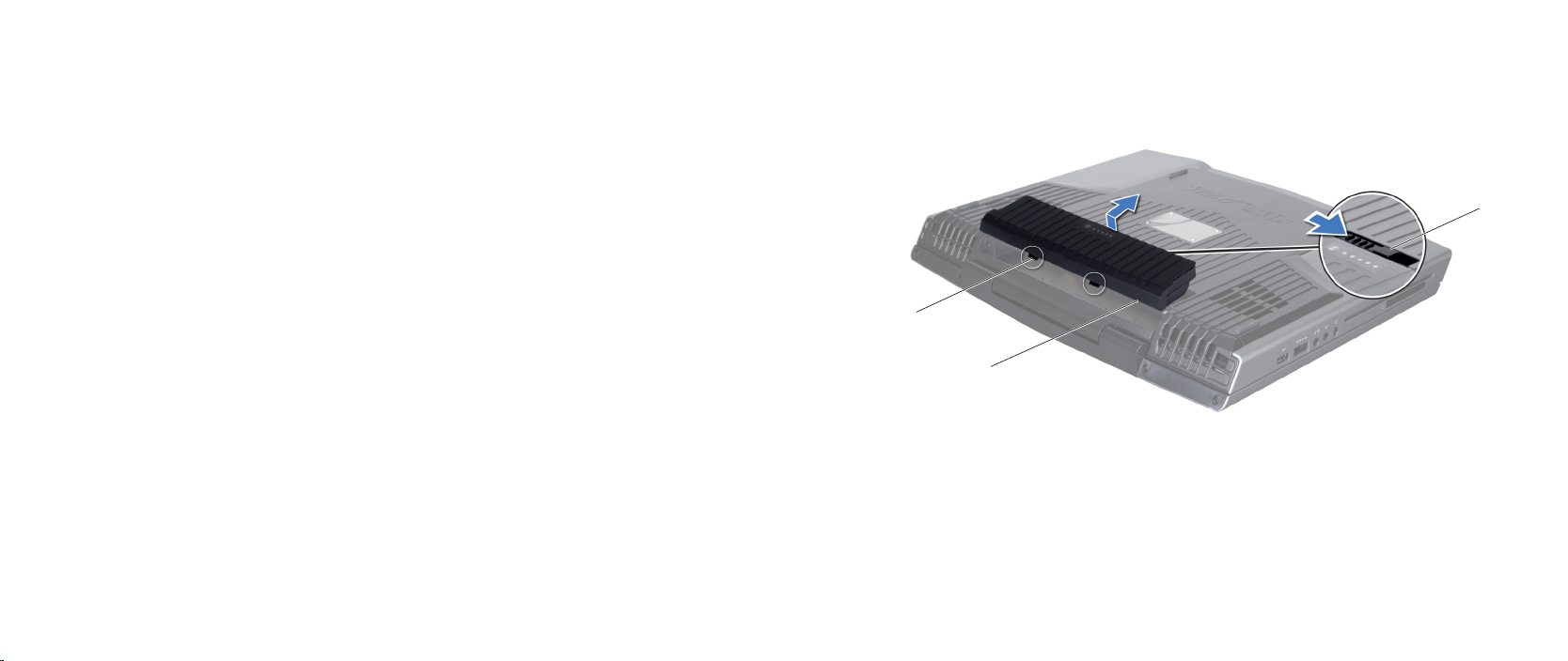
Removing the Battery Pack
Follow the instructions in “Before You Begin” on page 1. 6.
Turn the computer over.2.
Slide the battery latch to the unlock position as shown.3.
e battery pack will pop up.4.
Remove the battery pack.5.
Replacing the Battery Pack
Follow the instructions in “Before You Begin” on page 1. 6.
Align the battery pack tabs with the slots in the battery bay.2.
Push the battery pack into the battery bay until the battery pack clicks into 3.
place.
1 battery latch 3 battery pack tabs (2)
2 battery pack
011
/
011
Page 12

CHAPTER 3: COMPARTMENT DOOR
CHAPTER 3: COMPARTMENT DOOR
CHAPTER 3: COMPARTMENT DOOR
012
/
012
Page 13

Compartment Door
WARNING: Before working inside your computer, read the safety
information that shipped with your computer. For additional safety
best practices information, see the Regulatory Compliance Homepage
at www.dell.com/regulatory_compliance.
WARNING: Before performing these procedures, turn o the computer,
disconnect the AC adapter from the electrical outlet and the computer,
disconnect the modem from the wall connector and the computer, and
remove any other external cables from the computer.
CAUTION: Only a certied service technician should perform repairs on
your computer. Damage due to servicing that is not authorized by Dell™
is not covered by your warranty.
CAUTION: To avoid electrostatic discharge, ground yourself by using a
wrist grounding strap or by periodically touching an unpainted metal
surface (such as a connector on the back of the computer).
CAUTION: To help prevent damage to the system board, remove the
main battery (see “Removing the Battery Pack” on page 11) before
working inside the computer.
CHAPTER 3: COMPARTMENT DOOR
013
/
013
Page 14
CHAPTER 3: COMPARTMENT DOOR
2
3
1
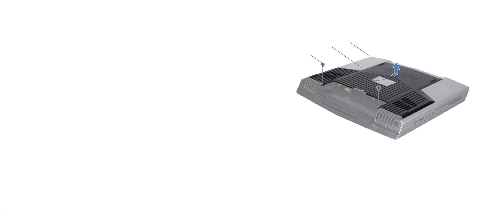
Removing the Compartment Door
Follow the instructions in “Before You Begin” on page 1. 6.
Remove the battery pack (see “Removing the Battery Pack” on page 2. 11).
Remove the two screws that secure the compartment door to the computer 3.
base.
Slide the compartment door towards the front of the computer and then lift 4.
it up.
Replacing the Compartment Door
Follow the instructions in “Before You Begin” on page 1. 6.
Place the compartment door on the computer base and slide it towards the 2.
back of the computer.
Replace the two screws that secure the compartment door to the computer 3.
base.
Replace the battery pack (see “Replacing the Battery Pack” on page 4. 11).
1 front of the computer 3 screws (2)
2 compartment door
014
/
014
Page 15

CHAPTER 4: HARD DRIVE
CHAPTER 4: HARD DRIVE
CHAPTER 4: HARD DRIVE
015
/
015
Page 16

Hard Drive
WARNING: Before working inside your computer, read the safety
information that shipped with your computer. For additional safety
best practices information, see the Regulatory Compliance Homepage
at www.dell.com/regulatory_compliance.
WARNING: Before performing these procedures, turn o the computer,
disconnect the AC adapter from the electrical outlet and the computer,
disconnect the modem from the wall connector and the computer, and
remove any other external cables from the computer.
WARNING: If you remove the hard drive from the computer when the
drive is hot, do not touch the metal housing of the hard drive.
CAUTION: Only a certied service technician should perform repairs on
your computer. Damage due to servicing that is not authorized by Dell™
is not covered by your warranty.
CAUTION: To prevent data loss, turn o your computer (see “Turning
O Your Computer” on page 7) before removing the hard drive. Do not
remove the hard drive while the computer is on or in Sleep state.
CAUTION: Hard drives are extremely fragile. Exercise care when
handling the hard drive.
CHAPTER 4: HARD DRIVE
CAUTION: To avoid electrostatic discharge, ground yourself by using a
wrist grounding strap or by periodically touching an unpainted metal
surface (such as a connector on the back of the computer).
CAUTION: To help prevent damage to the system board, remove the
main battery (see “Removing the Battery Pack” on page 11) before
working inside the computer.
NOTE: Dell does not guarantee compatibility or provide support for hard
drives from sources other than Dell or Alienware.
NOTE: If you are installing a hard drive from a source other than Dell or
Alienware, you need to install an operating system, drivers, and utilities
on the new hard drive.
016
/
016
Page 17
CHAPTER 4: HARD DRIVE
3
1
2
3
1
2
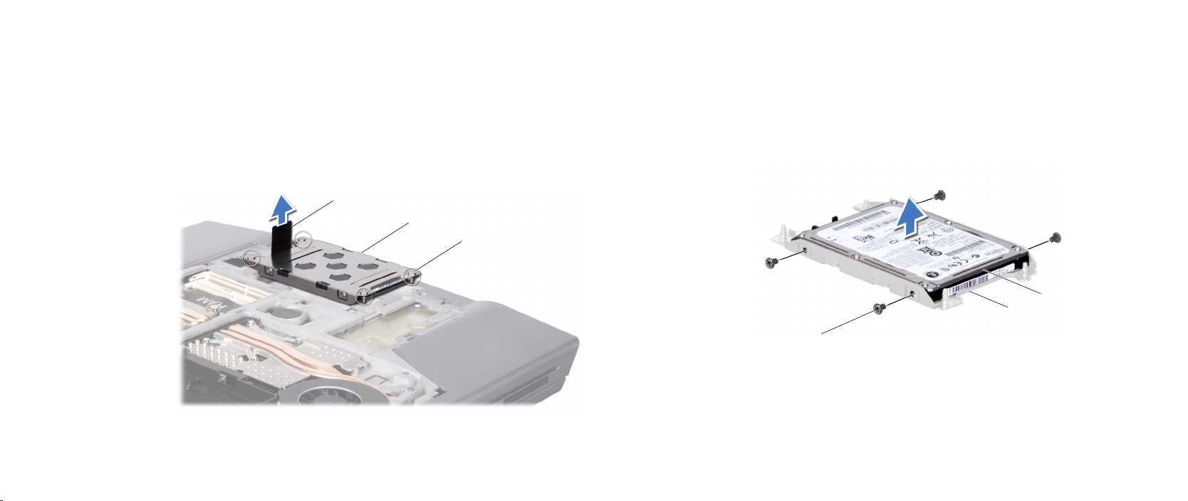
Removing the Hard Drive
Follow the instructions in “Before You Begin” on page 1. 6.
Remove the battery pack (see “Removing the Battery Pack” on page 2. 11).
Remove the compartment door (see “Removing the Compartment Door” on 3.
page 14).
Loosen the four captive screws that secure the hard-drive assembly.4.
Using the pull-tab, lift the hard-drive assembly out of the hard-drive bay.5.
1 pull-tab 3 captive screws (4)
2 hard-drive assembly
Remove the four screws that secure the hard drive to the hard-drive bracket.6.
Lift the hard drive out of the hard-drive bracket.7.
1 hard drive 3 screws (4)
2 hard-drive bracket
017
/
017
Page 18
CHAPTER 4: HARD DRIVE
1
2
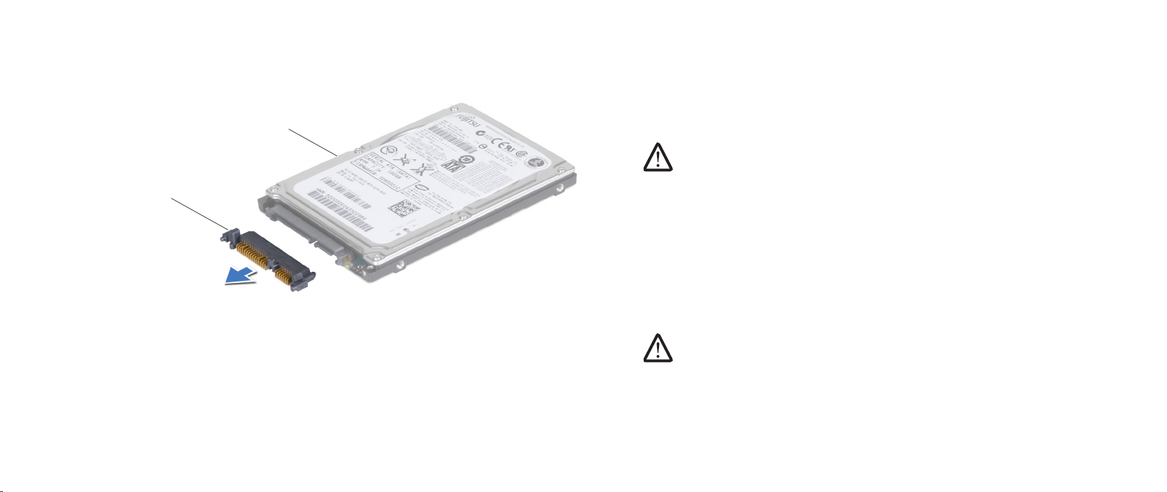
Disconnect the interposer from the hard drive.8.
Replacing the Hard Drive
Follow the instructions in “Before You Begin” on page 1. 6.
Remove the new drive from its packaging. 2.
Save the original packaging for storing or shipping the hard drive.
CAUTION: Use rm and even pressure to slide the drive into place. If
you use excessive force, you may damage the connector.
Connect the interposer to the hard drive.3.
Place the hard drive in the hard-drive bracket.4.
Replace the four screws that secure the hard drive to the hard-drive bracket.5.
Place the hard-drive assembly in the hard-drive bay.6.
Align and tighten the four captive screws that secure the hard-drive 7.
assembly to the hard-drive bay.
Replace the compartment door (see “Replacing the Compartment Door” on 8.
page 14).
Replace the battery pack (see “Replacing the Battery Pack” on page 9. 11).
CAUTION: Before turning on the computer, replace all screws and
1 interposer 2 hard drive
ensure that no stray screws remain inside the computer. Failure to do
so may result in damage to the computer.
Install the operating system for your computer, as needed.10.
Install the drivers and utilities for your computer, as needed.11.
018
/
018
Page 19

CHAPTER 5: MEMORY MODULE(S)
CHAPTER 5: MEMORY MODULE(S)
CHAPTER 5: MEMORY MODULE(S)
You can increase your computer memory by installing memory modules on
the system board. See the specications in your Mobile Manual or in the
Comprehensive Specications at support.dell.com/manuals for information on
the memory supported by your computer. Install only memory modules that are
supported by your computer.
NOTE: Memory modules purchased from Dell or Alienware are covered
under your computer warranty.
Your computer has two user-accessible SODIMM sockets that can be accessed
from the bottom of the computer.
019
/
019
Page 20

Memory Module(s)
WARNING: Before working inside your computer, read the safety
information that shipped with your computer. For additional safety
best practices information, see the Regulatory Compliance Homepage
at www.dell.com/regulatory_compliance.
WARNING: Before performing these procedures, turn o the computer,
disconnect the AC adapter from the electrical outlet and the computer,
disconnect the modem from the wall connector and the computer, and
remove any other external cables from the computer.
CAUTION: Only a certied service technician should perform repairs on
your computer. Damage due to servicing that is not authorized by Dell™
is not covered by your warranty.
CAUTION: To avoid electrostatic discharge, ground yourself by using a
wrist grounding strap or by periodically touching an unpainted metal
surface (such as a connector on the back of the computer).
CAUTION: To help prevent damage to the system board, remove the
main battery (see “Removing the Battery Pack” on page 11) before
working inside the computer.
CHAPTER 5: MEMORY MODULE(S)
020
/
020
Page 21
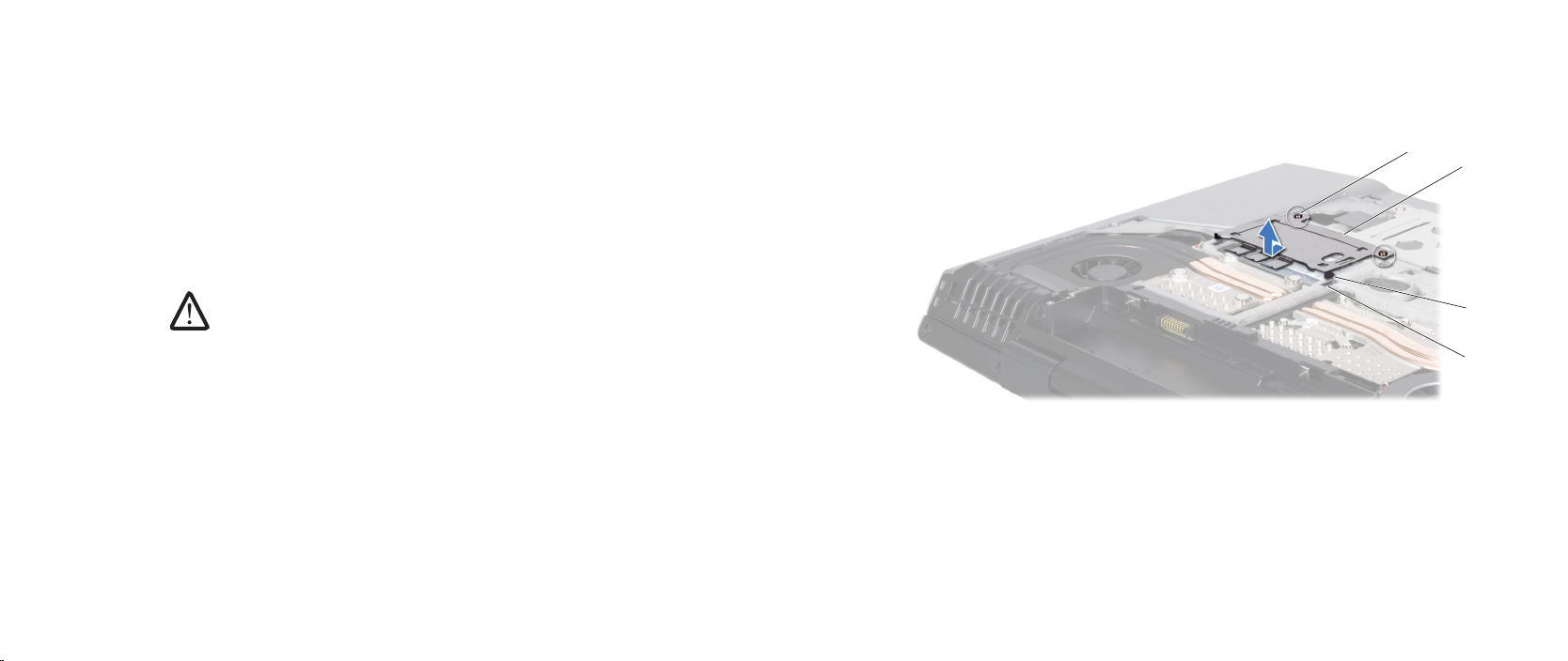
Removing the Memory Module(s)
4
3
2
1
Follow the instructions in “Before You Begin” on page 1. 6.
Remove the battery pack (see “Removing the Battery Pack” on page 2. 11).
Remove the compartment door (see “Removing the Compartment Door” on 3.
page 14).
Loosen the two captive screws that secure the memory-module door to the 4.
computer base.
Slide the memory-module door to release the tabs and lift the 5.
memory-module door out of the computer base.
CAUTION: If you need to remove memory modules from both
connectors, remove the memory module in the upper connector before
you remove the module in the lower connector.
CHAPTER 5: MEMORY MODULE(S)
1 slots (2) 3 memory-module door
2 tabs (2) 4 captive screws (2)
021
/
021
Page 22
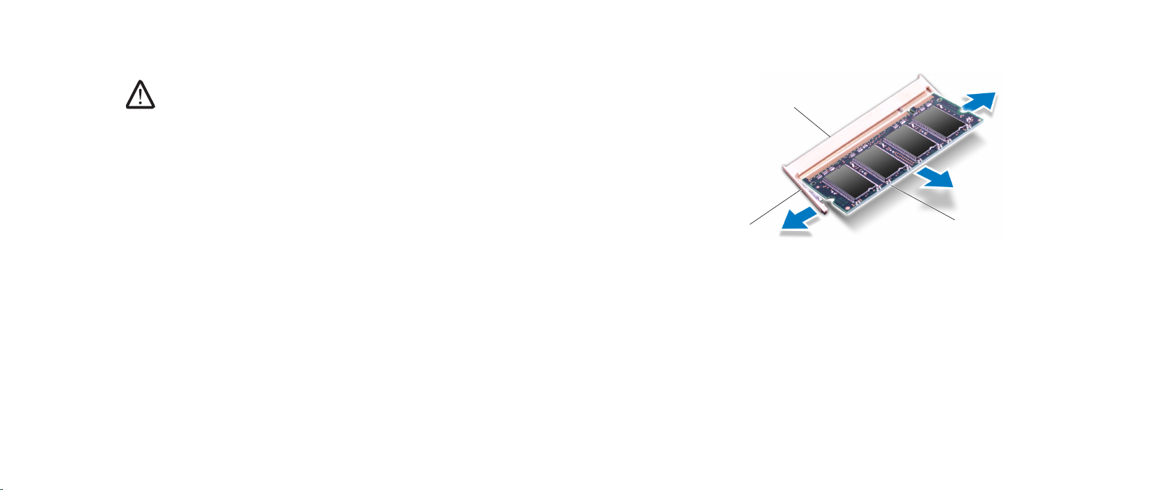
CAUTION: To prevent damage to the memory module connector(s), do
1
2
4
5
3
not use tools to spread the memory module spring-locks.
Use your ngertips to carefully spread apart the spring-locks on the 6.
memory-module connector until the memory module pops up.
Remove the memory module.7.
CHAPTER 5: MEMORY MODULE(S)
1 memory module 3 memory-module connector
2 spring-locks (2)
022
/
022
Page 23
3
4
1
2
Replacing the Memory Module(s)
CAUTION: If you need to install memory modules in two connectors,
install a memory module in the lower connector before you install a
module in the upper connector.
Follow the instructions in “Before You Begin” on page 1. 6.
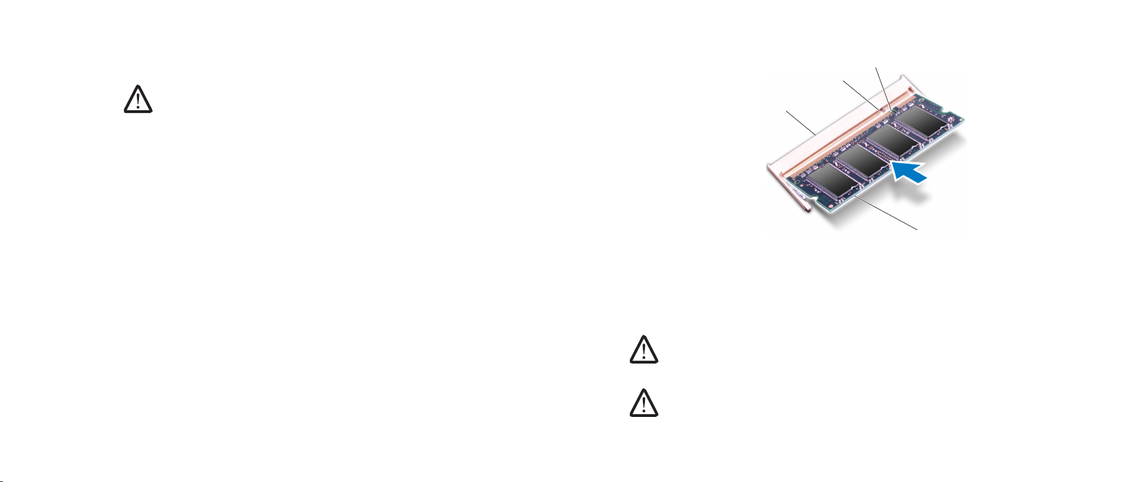
Align the notch on the memory module with the tab on the memory-module 2.
connector.
Insert the module into the memory-module connector at a 45-degree angle, 3.
and press the memory module down until it clicks into place. If you do not
hear the click, remove the module and reinstall it.
CHAPTER 5: MEMORY MODULE(S)
1 memory module 3 tab
2 memory-module connector 4 notch
CAUTION: If the memory-module door is difcult to close, remove the
memory module and reinstall it. Forcing the memory-module door to
close may damage your computer.
NOTE: If the memory module is not installed properly, the computer may
not boot.
023
/
023
Page 24

CHAPTER 5: MEMORY MODULE(S)
Align and insert the memory-module door tabs into the slots on the 4.
computer base.
Replace and tighten the two captive screws that secure the 5.
memory-module door to the computer base.
Replace the compartment door (see “Replacing the Compartment Door” on 6.
page 14).
Replace the battery pack (see “Replacing the Battery Pack” on page 7. 11).
CAUTION: Before turning on the computer, replace all screws and
ensure that no stray screws remain inside the computer. Failure to do
so may result in damage to the computer.
Turn on the computer.8.
As the computer boots, it detects the additional memory and automatically
updates the system conguration information. To conrm the amount of memory
installed in the computer:
Windows Vista®
Click Start → Control Panel→ System and Maintenance.
Windows® 7
Click Start → Control Panel→ System and Security→ System.
024
/
024
Page 25

CHAPTER 6: COIN-CELL BATTERY
CHAPTER 6: COIN-CELL BATTERY
CHAPTER 6: COIN-CELL BATTERY
025
/
025
Page 26

Coin-Cell Battery
WARNING: Before working inside your computer, read the safety
information that shipped with your computer. For additional safety
best practices information, see the Regulatory Compliance Homepage
at www.dell.com/regulatory_compliance.
WARNING: Before performing these procedures, turn o the computer,
disconnect the AC adapter from the electrical outlet and the computer,
disconnect the modem from the wall connector and the computer, and
remove any other external cables from the computer.
CAUTION: Only a certied service technician should perform repairs on
your computer. Damage due to servicing that is not authorized by Dell™
is not covered by your warranty.
CAUTION: To avoid electrostatic discharge, ground yourself by using a
wrist grounding strap or by periodically touching an unpainted metal
surface (such as a connector on the back of the computer).
CAUTION: To help prevent damage to the system board, remove the
main battery (see “Removing the Battery Pack” on page 11) before
working inside the computer.
CHAPTER 6: COIN-CELL BATTERY
026
/
026
Page 27
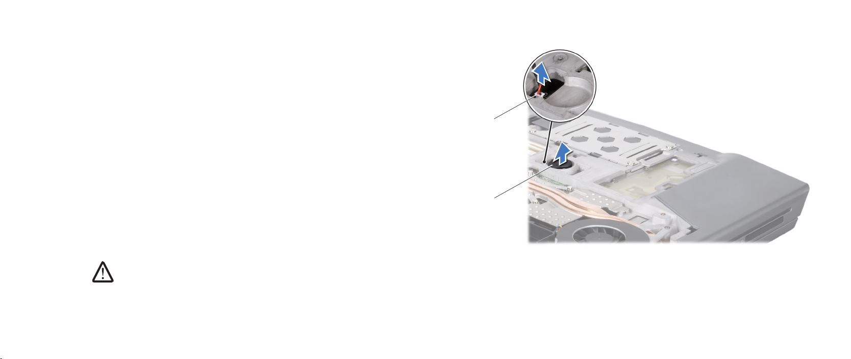
CHAPTER 6: COIN-CELL BATTERY
1
2
Removing the Coin-Cell Battery
Follow the instructions in “Before You Begin” on page 1. 6.
Remove the battery pack (see “Removing the Battery Pack” on page 2. 11).
Remove the compartment door (see “Removing the Compartment Door” on 3.
page 14).
e coin-cell battery is glued to the computer base, use a plastic scribe to 4.
pry it o the computer base.
Disconnect the coin-cell battery cable from the system board connector.5.
Replacing the Coin-Cell Battery
Follow the instructions in “Before You Begin” on page 1. 6.
Connect the coin-cell battery cable to the system board connector.2.
Use the adhesive on the coin-cell battery and adhere it to the computer 3.
base.
Replace the compartment door (see “Replacing the Compartment Door” on 4.
page 14).
Replace the battery pack (see “Replacing the Battery Pack” on page 5. 11).
CAUTION: Before turning on the computer, replace all screws and
ensure that no stray screws remain inside the computer. Failure to do
so may result in damage to the computer.
1 coin-cell battery cable connector 2 coin-cell battery
027
/
027
Page 28

CHAPTER 7: CENTER CONTROL COVER
CHAPTER 7: CENTER CONTROL COVER
CHAPTER 7: CENTER CONTROL COVER
028
/
028
Page 29

Center Control Cover
WARNING: Before working inside your computer, read the safety
information that shipped with your computer. For additional safety
best practices information, see the Regulatory Compliance Homepage
at www.dell.com/regulatory_compliance.
WARNING: Before performing these procedures, turn o the computer,
disconnect the AC adapter from the electrical outlet and the computer,
disconnect the modem from the wall connector and the computer, and
remove any other external cables from the computer.
CAUTION: Only a certied service technician should perform repairs on
your computer. Damage due to servicing that is not authorized by Dell™
is not covered by your warranty.
CAUTION: To avoid electrostatic discharge, ground yourself by using a
wrist grounding strap or by periodically touching an unpainted metal
surface (such as a connector on the back of the computer).
CAUTION: To help prevent damage to the system board, remove the
main battery (see “Removing the Battery Pack” on page 11) before
working inside the computer.
CHAPTER 7: CENTER CONTROL COVER
029
/
029
Page 30
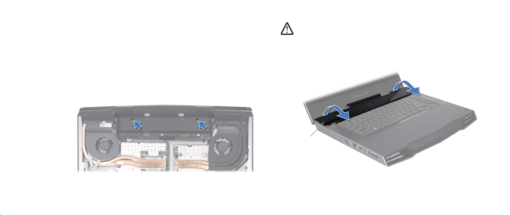
CHAPTER 7: CENTER CONTROL COVER
1
Removing the Center Control Cover
Follow the instructions in “Before You Begin” on page 1. 6.
Remove the battery pack (see “Removing the Battery Pack” on page 2. 11).
Remove the compartment door (see “Removing the Compartment Door” on 3.
page 14).
Remove the hard drive (see “Removing the Hard Drive” on page 4. 17).
Remove the memory module(s) (see “Removing the Memory Module(s)” on 5.
page 21).
Remove the two screws that secure the center control cover to the 6.
computer base.
Turn the computer top side up, and open the display as far as possible. 7.
CAUTION: Be extremely careful when removing the center control
cover. e center control cover along with the cable that attaches it to
the system board connector are very fragile.
Pry the center control cover up with a plastic scribe until you see the cable 8.
that attaches the center control cover to the system board connector.
Turn the center control cover as shown in the illustration.9.
1 center control cover
030
/
030
Page 31
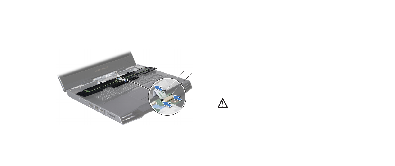
CHAPTER 7: CENTER CONTROL COVER
1
2
Release the connector latch to disconnect the cable from the center control 10.
cover connector.
Lift the center control cover o the computer.11.
1 cable 2 connector latch
Replacing the Center Control Cover
Follow the instructions in “Before You Begin” on page 1. 6.
Slide the cable into the center control cover connector and push in the 2.
connector latch to secure the cable to the connector.
Align the center control cover with the computer and snap the cover in 3.
place.
Turn the computer over and replace the two screws that secure the center 4.
control cover to the computer base.
Replace the memory module(s) (see “Replacing the Memory Module(s)” on 5.
page 23).
Replace the hard drive (see “Replacing the Hard Drive” on page 6. 18).
Replace the compartment door (see “Replacing the Compartment Door” on 7.
page 14).
Replace the battery pack (see “Replacing the Battery Pack” on page 8. 11).
CAUTION: Before turning on the computer, replace all screws and
ensure that no stray screws remain inside the computer. Failure to do
so may result in damage to the computer.
031
/
031
Page 32

CHAPTER 8: KEYBOARD
CHAPTER 8: KEYBOARD
CHAPTER 8: KEYBOARD
032
/
032
Page 33

Keyboard
WARNING: Before working inside your computer, read the safety
information that shipped with your computer. For additional safety
best practices information, see the Regulatory Compliance Homepage
at www.dell.com/regulatory_compliance.
WARNING: Before performing these procedures, turn o the computer,
disconnect the AC adapter from the electrical outlet and the computer,
disconnect the modem from the wall connector and the computer, and
remove any other external cables from the computer.
CAUTION: Only a certied service technician should perform repairs on
your computer. Damage due to servicing that is not authorized by Dell™
is not covered by your warranty.
CAUTION: To avoid electrostatic discharge, ground yourself by using a
wrist grounding strap or by periodically touching an unpainted metal
surface (such as a connector on the back of the computer).
CAUTION: To help prevent damage to the system board, remove the
main battery (see “Removing the Battery Pack” on page 11) before
working inside the computer.
CHAPTER 8: KEYBOARD
033
/
033
Page 34
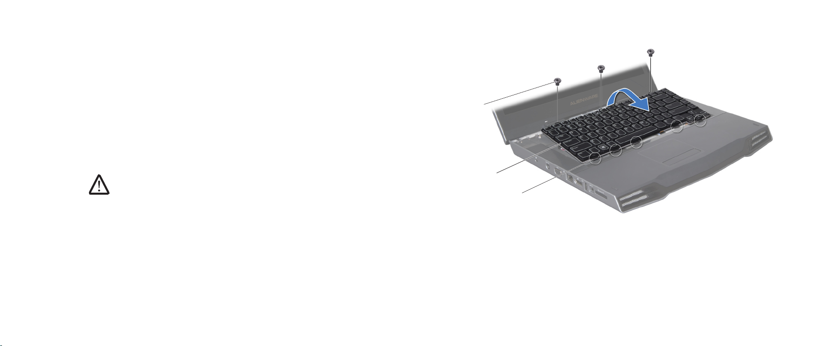
CHAPTER 8: KEYBOARD
1
2
3
Removing the Keyboard
Follow the instructions in “Before You Begin” on page 1. 6.
Remove the battery pack (see “Removing the Battery Pack” on page 2. 11).
Remove the compartment door (see “Removing the Compartment Door” on 3.
page 14).
Remove the hard drive (see “Removing the Hard Drive” on page 4. 17).
Remove the memory module(s) (see “Removing the Memory Module(s)” on 5.
page 21).
Remove the center control cover (see “Removing the Center Control Cover” 6.
on page 30).
Remove the three screws that secure the keyboard to the computer.7.
CAUTION: Be extremely careful when removing and handling the
keyboard. Failure to do so could result in scratching the display panel.
e keyboard along with the cables that attach it to the system board
connector are very fragile.
Lift and slide the keyboard until the tabs come out of the slots on the 8.
chassis.
1 tabs (5) 3 screws (3)
2 keyboard
034
/
034
Page 35
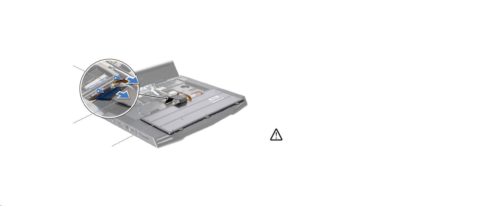
CHAPTER 8: KEYBOARD
2
1
3
Turn the keyboard over.9.
Release the connector latches and disconnect the keyboard cable and 10.
keyboard backlight cable from the respective system board connectors.
Lift the keyboard o the computer.11.
Replacing the Keyboard
Follow the instructions in “Before You Begin” on page 1. 6.
Slide the keyboard cable and the keyboard backlight cable into the 2.
respective system board connectors and push down the connector latches
to secure the cables to the connectors.
Align the tabs on the keyboard with the slots on the chassis.3.
Replace the three screws that secure the keyboard to the computer base.4.
Replace the center control cover (see “Replacing the Center Control Cover” 5.
on page 31).
Replace the memory module(s) (see “Replacing the Memory Module(s)” on 6.
page 23).
Replace the hard drive (see “Replacing the Hard Drive” on page 7. 18).
Replace the compartment door (see “Replacing the Compartment Door” on 8.
page 14).
Replace the battery pack (see “Replacing the Battery Pack” on page 9. 11).
CAUTION: Before turning on the computer, replace all screws and
ensure that no stray screws remain inside the computer. Failure to do
so may result in damage to the computer.
1 keyboard 3 keyboard backlight cable connector
2 keyboard cable
035
/
035
Page 36

CHAPTER 9: PALM REST
CHAPTER 9: PALM REST
CHAPTER 9: PALM REST
036
/
036
Page 37

Palm Rest
WARNING: Before working inside your computer, read the safety
information that shipped with your computer. For additional safety
best practices information, see the Regulatory Compliance Homepage
at www.dell.com/regulatory_compliance.
WARNING: Before performing these procedures, turn o the computer,
disconnect the AC adapter from the electrical outlet and the computer,
disconnect the modem from the wall connector and the computer, and
remove any other external cables from the computer.
CAUTION: Only a certied service technician should perform repairs on
your computer. Damage due to servicing that is not authorized by Dell™
is not covered by your warranty.
CAUTION: To avoid electrostatic discharge, ground yourself by using a
wrist grounding strap or by periodically touching an unpainted metal
surface (such as a connector on the back of the computer).
CAUTION: To help prevent damage to the system board, remove the
main battery (see “Removing the Battery Pack” on page 11) before
working inside the computer.
CHAPTER 9: PALM REST
037
/
037
Page 38
CHAPTER 9: PALM REST
1
Removing the Palm Rest
Follow the instructions in “Before You Begin” on page 1. 6.
Remove the battery pack (see “Removing the Battery Pack” on page 2. 11).
Remove the compartment door (see “Removing the Compartment Door” on 3.
page 14).
Remove the hard drive (see “Removing the Hard Drive” on page 4. 17).
Remove the memory module(s) (see “Removing the Memory Module(s)” on 5.
page 21).
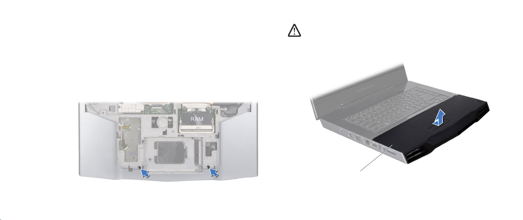
Remove the two screws that secure the palm rest to the computer base.6.
Turn the computer top side up, and open the display as far as possible.7.
CAUTION: Be extremely careful when removing the palm rest. e palm
rest along with the cable that connects the touch pad to the system
board connector are very fragile.
Slide and lift the palm rest out as shown in the illustration.8.
1 palm rest
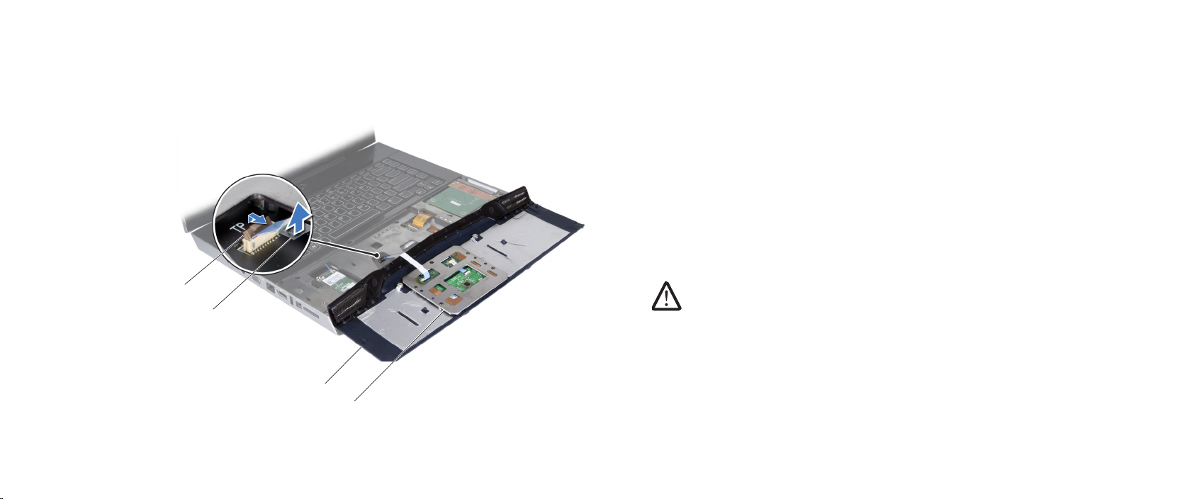
Ease the palm rest up until you see the cable that connects the touch pad to 9.
the system board connector.
038
/
038
Page 39
CHAPTER 9: PALM REST
2
3
4
1
Turn the palm rest over and release the connector latch on the system 10.
board connector.
Pull on the pull-tab to disconnect the cable from the system board connector.11.
Lift the palm rest o the computer.12.
Replacing the Palm Rest
Follow the instructions in “Before You Begin” on page 1. 6.
Slide the touch pad cable into the system board connector and push down 2.
the connector latch to secure the cable to the connector.
Press and slide the palm rest into position.3.
Turn the computer over and replace the two screws that secure the palm 4.
rest to the computer base.
Replace the memory module(s) (see “Replacing the Memory Module(s)” on 5.
page 23).
Replace the hard drive (see “Replacing the Hard Drive” on page 6. 18).
Replace the compartment door (see “Replacing the Compartment Door” on 7.
page 14).
Replace the battery pack (see “Replacing the Battery Pack” on page 8. 11).
CAUTION: Before turning on the computer, replace all screws and
ensure that no stray screws remain inside the computer. Failure to do
so may result in damage to the computer.
1 touch pad 3 pull-tab
2 palm rest 4 connector latch
039
/
039
Page 40

CHAPTER 10: AIR VENTS
CHAPTER 10: AIR VENTS
CHAPTER 10: AIR VENTS
040
/
040
Page 41

Air Vents
WARNING: Before working inside your computer, read the safety
information that shipped with your computer. For additional safety
best practices information, see the Regulatory Compliance Homepage
at www.dell.com/regulatory_compliance.
WARNING: Before performing these procedures, turn o the computer,
disconnect the AC adapter from the electrical outlet and the computer,
disconnect the modem from the wall connector and the computer, and
remove any other external cables from the computer.
CAUTION: Only a certied service technician should perform repairs on
your computer. Damage due to servicing that is not authorized by Dell™
is not covered by your warranty.
CAUTION: To avoid electrostatic discharge, ground yourself by using a
wrist grounding strap or by periodically touching an unpainted metal
surface (such as a connector on the back of the computer).
CAUTION: To help prevent damage to the system board, remove the
main battery (see “Removing the Battery Pack” on page 11) before
working inside the computer.
CHAPTER 10: AIR VENTS
041
/
041
Page 42

CHAPTER 10: AIR VENTS
1
Removing the Air Vents
Follow the instructions in “Before You Begin” on page 1. 6.
Remove the battery pack (see “Removing the Battery Pack” on page 2. 11).
Remove the compartment door (see “Removing the Compartment Door” on 3.
page 14).
Remove the hard drive (see “Removing the Hard Drive” on page 4. 17).
Remove the memory module(s) (see “Removing the Memory Module(s)” on 5.
page 21).
Remove the center control cover (see “Removing the Center Control Cover” 6.
on page 30).
Remove the four screws that secure the air vents to the computer base.7.
1 screws (4)
042
/
042
Page 43
CHAPTER 10: AIR VENTS
1
2
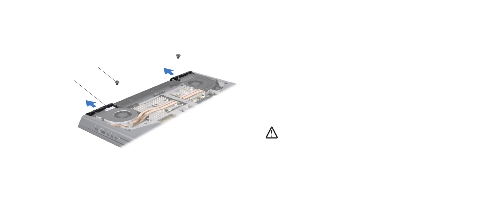
Turn the computer over and remove the two screws from the bottom of the 8.
computer.
Pull the air vents out of the computer.9.
Replacing the Air Vents
Follow the instructions in “Before You Begin” on page 1. 6.
Replace the air vents on the computer base.2.
Replace the two screws that secure the air vents to the bottom of the 3.
computer.
Turn the computer over and replace the four screws that secure the air 4.
vents to the computer base.
Replace the center control cover (see “Replacing the Center Control Cover” 5.
on page 31).
Replace the memory module(s) (see “Replacing the Memory Module(s)” on 6.
page 23).
Replace the hard drive (see “Replacing the Hard Drive” on page 7. 18).
Replace the compartment door (see “Replacing the Compartment Door” on 8.
page 14).
Replace the battery pack (see “Replacing the Battery Pack” on page 9. 11).
CAUTION: Before turning on the computer, replace all screws and
ensure that no stray screws remain inside the computer. Failure to do
so may result in damage to the computer.
1 air vents (2) 2 screws (2)
043
/
043
Page 44

CHAPTER 11: WIRELESS MINI-CARD(S)
CHAPTER 11: WIRELESS MINI-CARD(S)
CHAPTER 11: WIRELESS MINI-CARD(S)
If you ordered a wireless Mini-Card with your computer, the card is already
installed.
Your computer supports the following types of cards:
Wireless Local Area Network (WLAN) — Half Mini-Card•
Wireless Personal Area Network (WPAN) or Internal Card with Bluetooth•
Wireless Technology — Full Mini-Card
NOTE: e WLAN slot supports a half Mini-Card.
NOTE: Depending on the conguration of the computer when it was sold,
one or more of the Mini-Card slots may not have Mini-Cards installed in
them.
®
044
/
044
Page 45

Wireless Mini-Card(s)
WARNING: Before working inside your computer, read the safety
information that shipped with your computer. For additional safety
best practices information, see the Regulatory Compliance Homepage
at www.dell.com/regulatory_compliance.
WARNING: Before performing these procedures, turn o the computer,
disconnect the AC adapter from the electrical outlet and the computer,
disconnect the modem from the wall connector and the computer, and
remove any other external cables from the computer.
CAUTION: Only a certied service technician should perform repairs on
your computer. Damage due to servicing that is not authorized by Dell™
is not covered by your warranty.
CAUTION: To avoid electrostatic discharge, ground yourself by using a
wrist grounding strap or by periodically touching an unpainted metal
surface (such as a connector on the back of the computer).
CAUTION: To help prevent damage to the system board, remove the
main battery (see “Removing the Battery Pack” on page 11) before
working inside the computer.
CHAPTER 11: WIRELESS MINI-CARD(S)
045
/
045
Page 46
1
2
4
3
Removing the Half Mini-Card
Follow the instructions in “Before You Begin” on page 1. 6.
Remove the battery pack (see “Removing the Battery Pack” on page 2. 8).
Remove the compartment door (see “Removing the Compartment Door” on 3.
page 14).
Remove the hard drive (see “Removing the Hard Drive” on page 4. 17).
Remove the memory module(s) (see “Removing the Memory Module(s)” on 5.
page 21).
Remove the center control cover (see “Removing the Center Control Cover” 6.
on page 30).
Remove the keyboard (see “Removing the Keyboard” on page 7. 34).
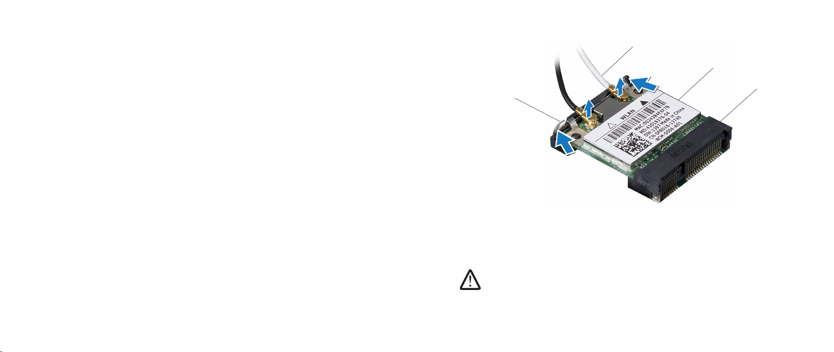
Disconnect the antenna cables from the half Mini-Card.8.
Push out the securing clips until the half Mini-Card pops up.9.
CHAPTER 11: WIRELESS MINI-CARD(S)
1 system board connector 3 antenna cables (2 or 3)
2 half Mini-Card 4 securing clips (2)
Remove the half Mini-Card from the system board connector.10.
CAUTION: When the half Mini-Card is not in the computer, store it in
protective antistatic packaging. For more information, see “Protecting
Against Electrostatic Discharge” in the safety information that shipped
with your computer.
046
/
046
Page 47

CHAPTER 11: WIRELESS MINI-CARD(S)
Replacing the Half Mini-Card
Follow the instructions in “Before You Begin” on page 1. 6.
Remove the new half Mini-Card from its packaging. 2.
CAUTION: Use rm and even pressure to slide the card into place. If you
use excessive force, you may damage the connector.
Align the notch on the card with the tab on the system board connector.3.
Insert the half Mini-Card at a 45-degree angle into the appropriate system 4.
board connector. For example, the WLAN card connector is labeled WLAN
and so on.
Press the other end of the half Mini-Card down into the slot on the system 5.
board until it clicks into place.
Connect the appropriate antenna cables to the half Mini-Card you are 6.
installing. e following table provides the antenna cable color scheme for
the half Mini-Card supported by your computer.
Connectors on the Mini-Card Antenna Cable Color Scheme
WLAN (2 or 3 antenna cables):
Main WLAN (white triangle)
Auxiliary WLAN (black triangle)
MIMO WLAN (gray triangle)
(optional)
white
black
gray
Replace the keyboard (see “Replacing the Keyboard” on page 7. 35).
Replace the center control cover (see “Replacing the Center Control Cover” 8.
on page 31).
Replace the memory module(s) (see “Replacing the Memory Module(s)” on 9.
page 21).
Replace the hard drive (see “Replacing the Hard Drive” on page 10. 18).
Replace the compartment door (see “Replacing the Compartment Door” on 11.
page 14).
Replace the battery pack (see “Replacing the Battery Pack” on page 12. 11).
047
/
047
Page 48
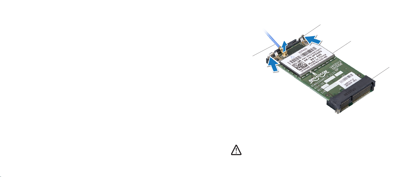
1
2
3
4
Removing the Full Mini-Card
Follow the instructions in “Before You Begin” on page 1. 6.
Remove the battery pack (see “Removing the Battery Pack” on page 2. 11).
Remove the compartment door (see “Removing the Compartment Door” on 3.
page 14).
Remove the hard drive (see “Removing the Hard Drive” on page 4. 17).
Remove the memory module(s) (see “Removing the Memory Module(s)” on 5.
page 21).
Remove the palm rest (see “Removing the Palm Rest” on page 6. 38).
Disconnect the blue antenna cable from the full Mini-Card.7.
Push out the securing clips until the full Mini-Card pops up.8.
CHAPTER 11: WIRELESS MINI-CARD(S)
1 system board connector 3 securing clips (2)
2 full Mini-Card 4 antenna cable
Remove the full Mini-Card from the system board connector.9.
CAUTION: When the full Mini-Card is not in the computer, store it in
protective antistatic packaging. For more information, see “Protecting
Against Electrostatic Discharge” in the safety information that shipped
with your computer.
048
/
048
Page 49

CHAPTER 11: WIRELESS MINI-CARD(S)
Replacing the Full Mini-Card
Follow the instructions in “Before You Begin” on page 1. 6.
Remove the new full Mini-Card from its packaging. 2.
CAUTION: Use rm and even pressure to slide the card into place. If you
use excessive force, you may damage the connector.
Align the notch on the card with the tab on the connector.3.
Insert the full Mini-Card at a 45-degree angle into the appropriate system 4.
board connector. For example, the WPAN card connector is labeled WPAN
and so on.
Press the other end of the full Mini-Card down into the slot on the system 5.
board until it clicks into place.
Connect the blue antenna cable to the full Mini-Card you are installing. 6.
Replace the palm rest (see “Replacing the Palm Rest” on page 7. 39).
Replace the memory module(s) (see “Replacing the Memory Module(s)” on 8.
page 23).
Replace the hard drive (see “Replacing the Hard Drive” on page 9. 18).
Replace the compartment door (see “Replacing the Compartment Door” on 10.
page 14).
Replace the battery pack (see “Replacing the Battery Pack” on page 11. 11).
CAUTION: Before turning on the computer, replace all screws and
ensure that no stray screws remain inside the computer. Failure to do
so may result in damage to the computer.
Install the drivers and utilities for your computer, as required.12.
NOTE: If you are installing a communication card from a source other
than Dell or Alienware, you must install the appropriate drivers and
utilities.
049
/
049
Page 50

CHAPTER 12: PROCESSOR FAN AND HEAT SINK ASSEMBLY
CHAPTER 12: PROCESSOR FAN AND
HEAT SINK ASSEMBLY
CHAPTER 12: PROCESSOR FAN AND HEAT SINK ASSEMBLY
050
/
050
Page 51

Processor Fan and Heat Sink Assembly
WARNING: Before working inside your computer, read the safety
information that shipped with your computer. For additional safety
best practices information, see the Regulatory Compliance Homepage
at www.dell.com/regulatory_compliance.
WARNING: Before performing these procedures, turn o the computer,
disconnect the AC adapter from the electrical outlet and the computer,
disconnect the modem from the wall connector and the computer, and
remove any other external cables from the computer.
CAUTION: Only a certied service technician should perform repairs on
your computer. Damage due to servicing that is not authorized by Dell™
is not covered by your warranty.
CAUTION: To avoid electrostatic discharge, ground yourself by using a
wrist grounding strap or by periodically touching an unpainted metal
surface (such as a connector on the back of the computer).
CAUTION: To help prevent damage to the system board, remove the
main battery (see “Removing the Battery Pack” on page 11) before
working inside the computer.
CHAPTER 12: PROCESSOR FAN AND HEAT SINK ASSEMBLY
051
/
051
Page 52
Removing the Processor Fan and Heat Sink Assembly
Follow the instructions in “Before You Begin” on page 1. 6.
Remove the battery pack (see “Removing the Battery Pack” on page 2. 11).
Remove the compartment door (see “Removing the Compartment Door” on 3.
page 14).
Remove the hard drive (see “Removing the Hard Drive” on page 4. 17).
Remove the memory module(s) (see “Removing the Memory Module(s)” on 5.
page 21).
Remove the center control cover (see “Removing the Center Control Cover” 6.
on page 30).
Remove the right air-vent (see “Removing the Air Vents” on page 7. 42).
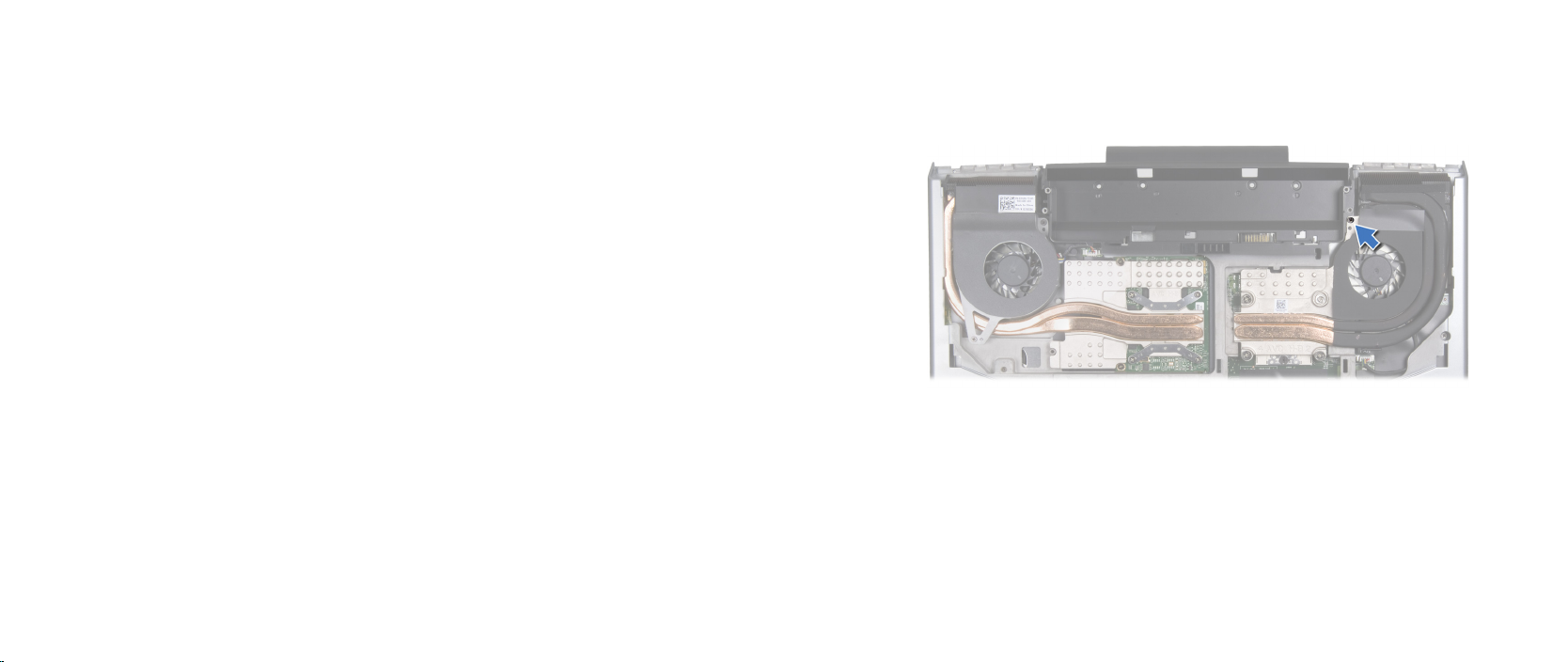
Loosen the captive screw that secures the processor fan and heat sink 8.
assembly to the computer base.
CHAPTER 12: PROCESSOR FAN AND HEAT SINK ASSEMBLY
052
/
052
Page 53
3
2
1
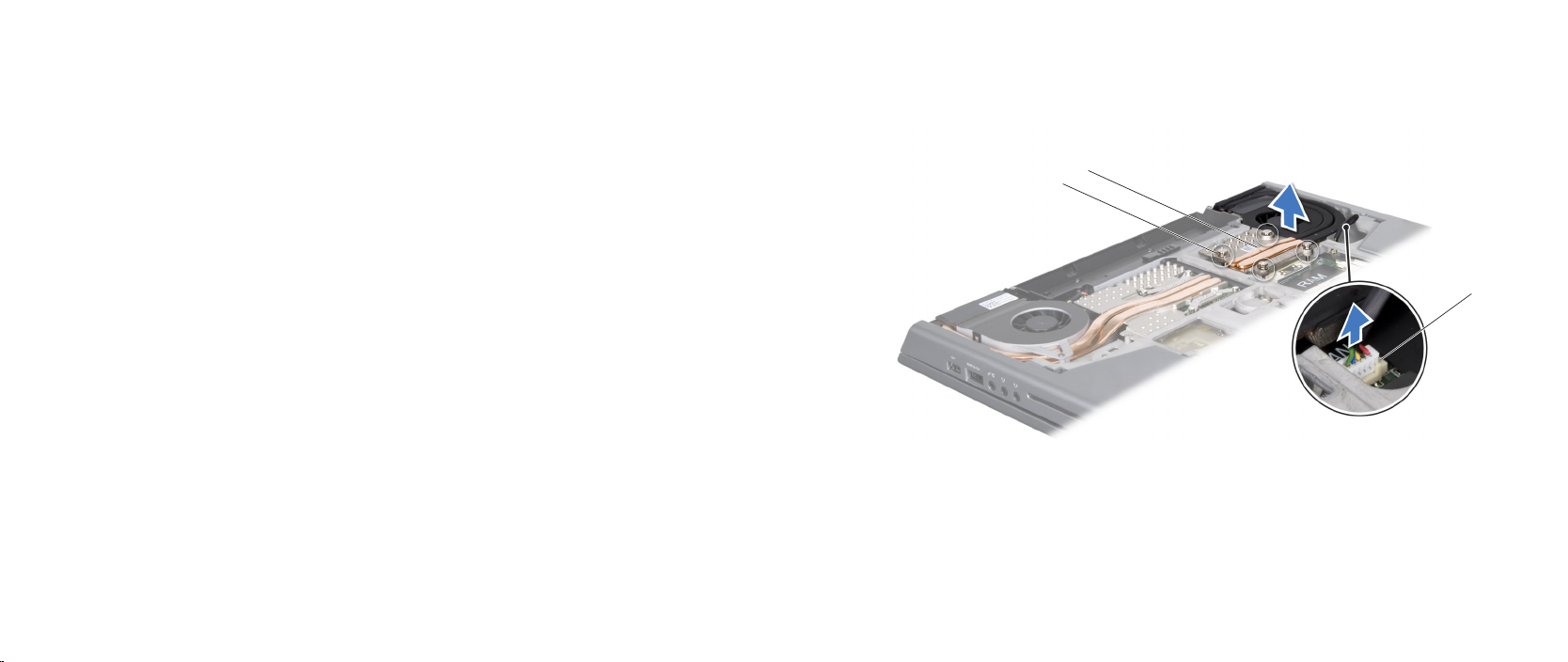
Disconnect the processor fan and heat sink assembly cable from the system 9.
board connector.
In sequential order (indicated on the processor fan and heat sink assembly), 10.
loosen the four captive screws that secure the processor fan and heat sink
assembly to the system board.
Lift the processor fan and heat sink assembly o the system board. 11.
CHAPTER 12: PROCESSOR FAN AND HEAT SINK ASSEMBLY
1 processor fan and heat sink
assembly cable connector
3 processor fan and heat sink
assembly
2 captive screws (4)
053
/
053
Page 54

CHAPTER 12: PROCESSOR FAN AND HEAT SINK ASSEMBLY
Replacing the Processor Fan and Heat Sink Assembly
Follow the instructions in “Before You Begin” on page 1. 6.
Peel the backing o the thermal cooling pads attached to the new processor 2.
fan and heat sink assembly.
NOTE: If the processor fan and heat sink assembly is replaced, the
thermal cooling pads will be attached to the new processor fan and heat
sink assembly. Do not reuse the old thermal cooling pads.
Place the processor fan and heat sink assembly on the system board. 3.
Align the four captive screws on the processor heat sink with the screw 4.
holes on the system board and tighten the screws in sequential order
(indicated on the processor fan and heat sink assembly).
Tighten the screw that secures the processor fan and heat sink assembly to 5.
the computer base.
Connect the processor fan and heat sink assembly cable to the system 6.
board connector.
Replace the right air-vent (see “Replacing the Air Vents” on page 7. 43).
Replace the center control cover (see “Replacing the Center Control Cover” 8.
on page 31).
Replace the memory module(s) (see “Replacing the Memory Module(s)” on 9.
page 23).
Replace the hard drive (see “Replacing the Hard Drive” on page 10. 18).
Replace the compartment door (see “Replacing the Compartment Door” on 11.
page 14).
Replace the battery pack (see “Replacing the Battery Pack” on page 12. 11).
CAUTION: Before turning on the computer, replace all screws and
ensure that no stray screws remain inside the computer. Failure to do
so may result in damage to the computer.
054
/
054
Page 55

CHAPTER 13: PROCESSOR
CHAPTER 13: PROCESSOR
CHAPTER 13: PROCESSOR
055
/
055
Page 56

Processor
WARNING: Before working inside your computer, read the safety
information that shipped with your computer. For additional safety
best practices information, see the Regulatory Compliance Homepage
at www.dell.com/regulatory_compliance.
WARNING: Before performing these procedures, turn o the computer,
disconnect the AC adapter from the electrical outlet and the computer,
disconnect the modem from the wall connector and the computer, and
remove any other external cables from the computer.
CAUTION: Only a certied service technician should perform repairs on
your computer. Damage due to servicing that is not authorized by Dell™
is not covered by your warranty.
CHAPTER 13: PROCESSOR
CAUTION: To prevent intermittent contact between the ZIF-socket cam
screw and the processor when removing or replacing the processor,
press to apply slight pressure to the center of the processor while
turning the cam screw.
CAUTION: To avoid damage to the processor, hold the screwdriver so
that it is perpendicular to the processor when turning the cam screw.
CAUTION: To avoid electrostatic discharge, ground yourself by using a
wrist grounding strap or by periodically touching an unpainted metal
surface (such as a connector on the back of the computer).
CAUTION: To help prevent damage to the system board, remove the
main battery (see “Removing the Battery Pack” on page 11) before
working inside the computer.
056
/
056
Page 57
1
2
3
4
Removing the Processor
Follow the instructions in “Before You Begin” on page 1. 6.
Remove the battery pack (see “Removing the Battery Pack” on page 2. 11).
Remove the compartment door (see “Removing the Compartment Door” on 3.
page 14).
Remove the hard drive (see “Removing the Hard Drive” on page 4. 17).
Remove the memory module(s) (see “Removing the Memory Module(s)” on 5.
page 21).
Remove the center control cover (see “Removing the Center Control Cover” 6.
on page 30).
Remove the right air-vent (see “Removing the Air Vents” on page 7. 42).
Remove the processor fan and heat sink assembly (see “Removing the 8.
Processor Fan and Heat Sink Assembly” on page 52).
CAUTION: When removing the processor, pull it straight up. Be careful
not to bend the pins on the processor.
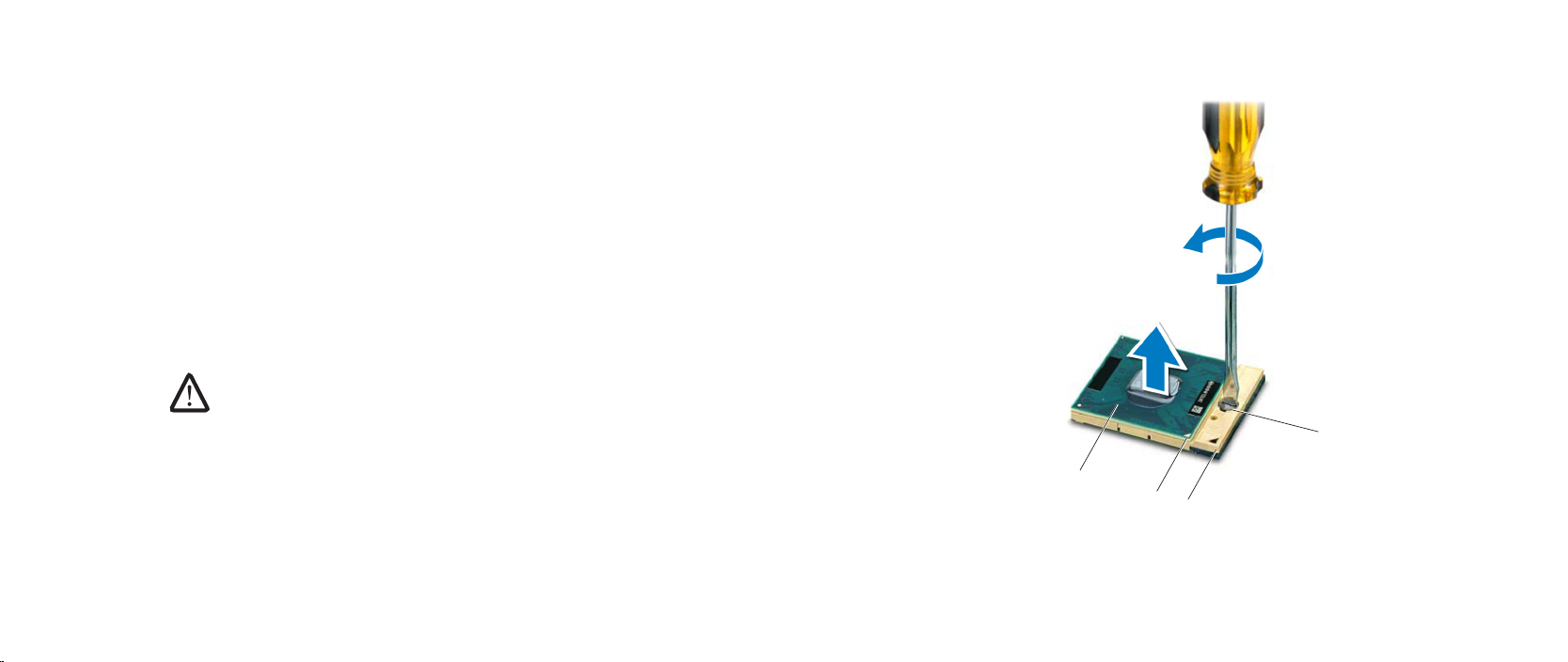
To loosen the ZIF socket, use a small at-blade screwdriver and rotate the 9.
ZIF-socket cam screw counterclockwise until it comes to the cam stop.
e ZIF-socket cam screw secures the processor to the system board. Take
note of the arrow on the ZIF-socket cam screw.
Lift the processor o the ZIF socket. 10.
CHAPTER 13: PROCESSOR
1 processor 3 ZIF socket
2 pin-1 corner of processor 4 ZIF-socket cam screw
057
/
057
Page 58

CHAPTER 13: PROCESSOR
Replacing the Processor
Follow the instructions in “Before You Begin” on page 1. 6.
CAUTION: Ensure that the cam lock is in the fully open position before
seating the processor. Seating the processor properly in the ZIF socket
does not require force.
CAUTION: A processor that is not properly seated can result in an
intermittent connection or permanent damage to the processor and
ZIF socket.
Align the pin-1 corner of the processor so that it points to the triangle on the 2.
ZIF socket, and insert the processor into the ZIF socket.
When the processor is correctly seated, all four corners are aligned at the
same height. If one or more corners of the processor are higher than the
others, the processor is not seated correctly.
CAUTION: To prevent intermittent contact between the ZIF-socket cam
screw and the processor when removing or replacing the processor,
press to apply slight pressure to the center of the processor while
turning the cam screw.
Tighten the ZIF socket by turning the cam screw clockwise to secure the 3.
processor to the system board.
CAUTION: If the processor, processor fan and heat sink assembly, or
system board is replaced, use the thermal cooling pads provided in the
replacement kit to ensure that thermal conductivity is achieved. Do
not reuse the old thermal cooling pads.
Peel the backing o the new thermal cooling pads in the kit and adhere the 4.
pads to the portions of the processor fan and heat sink assembly that cover
the processor.
Replace the processor fan and heat sink assembly (see “Replacing the 5.
Processor Fan and Heat Sink Assembly” on page 54).
Replace the right air-vent (see “Replacing the Air Vents” on page 6. 43).
Replace the center control cover (see “Replacing the Center Control Cover” 7.
on page 31).
Replace the memory module(s) (see “Replacing the Memory Module(s)” on 8.
page 23).
Replace the hard drive (see “Replacing the Hard Drive” on page 9. 18).
Replace the compartment door (see “Replacing the Compartment Door” on 10.
page 14).
Replace the battery pack (see “Replacing the Battery Pack” on page 11. 11).
CAUTION: Before turning on the computer, replace all screws and
ensure that no stray screws remain inside the computer. Failure to do
so may result in damage to the computer.
058
/
058
Page 59

CHAPTER 14: GRAPHICS CARD FAN
CHAPTER 14: GRAPHICS CARD FAN
CHAPTER 14: GRAPHICS CARD FAN
059
/
059
Page 60

Graphics Card Fan
WARNING: Before working inside your computer, read the safety
information that shipped with your computer. For additional safety
best practices information, see the Regulatory Compliance Homepage
at www.dell.com/regulatory_compliance.
WARNING: Before performing these procedures, turn o the computer,
disconnect the AC adapter from the electrical outlet and the computer,
disconnect the modem from the wall connector and the computer, and
remove any other external cables from the computer.
CAUTION: Only a certied service technician should perform repairs on
your computer. Damage due to servicing that is not authorized by Dell™
is not covered by your warranty.
CAUTION: To avoid electrostatic discharge, ground yourself by using a
wrist grounding strap or by periodically touching an unpainted metal
surface (such as a connector on the back of the computer).
CAUTION: To help prevent damage to the system board, remove the
main battery (see “Removing the Battery Pack” on page 11) before
working inside the computer.
CHAPTER 14: GRAPHICS CARD FAN
060
/
060
Page 61

Removing the Graphics Card Fan
Follow the instructions in “Before You Begin” on page 1. 6.
Remove the battery pack (see “Removing the Battery Pack” on page 2. 11).
Remove the compartment door (see “Removing the Compartment Door” on 3.
page 14).
Remove the hard drive (see “Removing the Hard Drive” on page 4. 17).
Remove the memory module(s) (see “Removing the Memory Module(s)” on 5.
page 21).
Loosen the two captive screws that secure the graphics card fan to the 6.
computer base.
CHAPTER 14: GRAPHICS CARD FAN
061
/
061
Page 62
CHAPTER 14: GRAPHICS CARD FAN
1
2
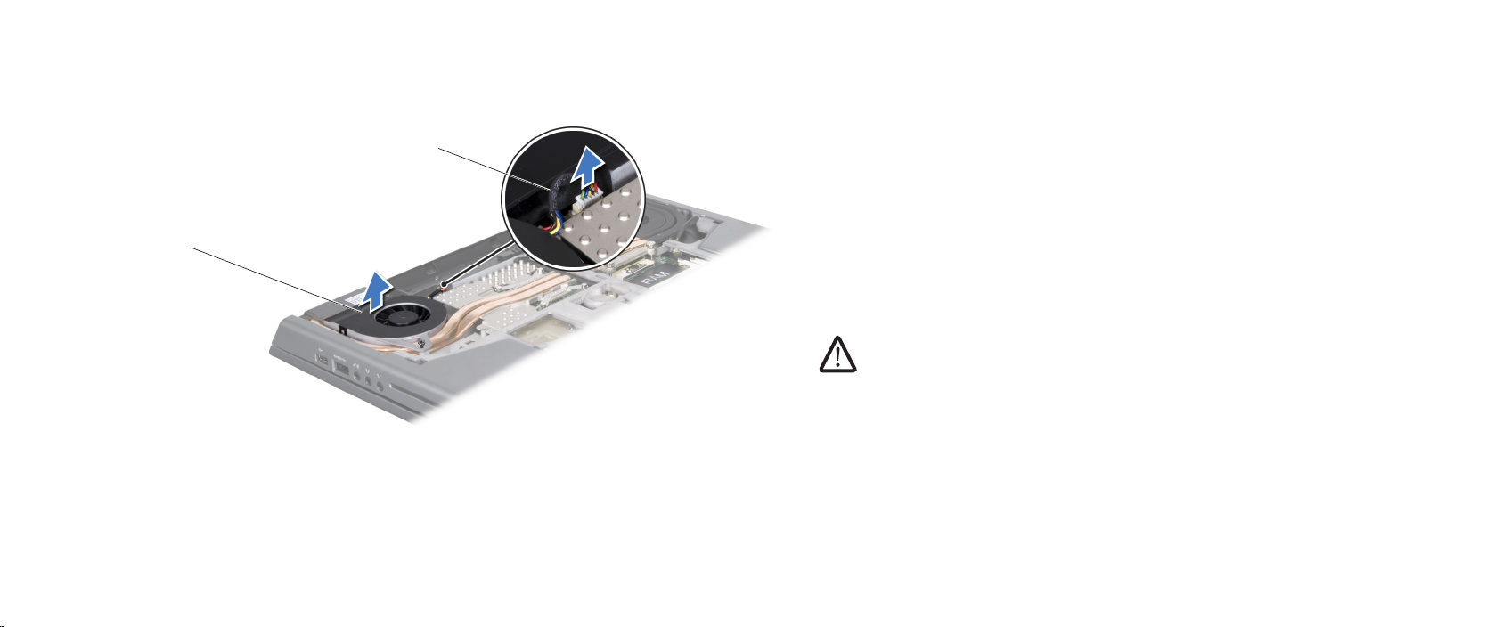
Disconnect the graphics card fan cable from the system board connector.7.
Lift the graphics card fan o the computer base.8.
Replacing the Graphics Card Fan
Follow the instructions in “Before You Begin” on page 1. 6.
Place the graphics card fan in the computer base. 2.
Connect the graphics card fan cable to the system board connector.3.
Tighten the two captive screws that secure the graphics card fan to the 4.
computer base.
Replace the memory module(s) (see “Replacing the Memory Module(s)” on 5.
page 23).
Replace the hard drive (see “Replacing the Hard Drive” on page 6. 18).
Replace the compartment door (see “Replacing the Compartment Door” on 7.
page 14).
Replace the battery pack (see “Replacing the Battery Pack” on page 8. 11).
CAUTION: Before turning on the computer, replace all screws and
ensure that no stray screws remain inside the computer. Failure to do
so may result in damage to the computer.
1 graphics card fan 2 graphics card fan cable
062
/
062
Page 63

CHAPTER 15: GRAPHICS CARD HEAT SINK
CHAPTER 15: GRAPHICS CARD HEAT SINK
CHAPTER 15: GRAPHICS CARD HEAT SINK
063
/
063
Page 64

Graphics Card Heat Sink
WARNING: Before working inside your computer, read the safety
information that shipped with your computer. For additional safety
best practices information, see the Regulatory Compliance Homepage
at www.dell.com/regulatory_compliance.
WARNING: Before performing these procedures, turn o the computer,
disconnect the AC adapter from the electrical outlet and the computer,
disconnect the modem from the wall connector and the computer, and
remove any other external cables from the computer.
CAUTION: Only a certied service technician should perform repairs on
your computer. Damage due to servicing that is not authorized by Dell™
is not covered by your warranty.
CAUTION: To avoid electrostatic discharge, ground yourself by using a
wrist grounding strap or by periodically touching an unpainted metal
surface (such as a connector on the back of the computer).
CAUTION: To help prevent damage to the system board, remove the
main battery (see “Removing the Battery Pack” on page 11) before
working inside the computer.
CHAPTER 15: GRAPHICS CARD HEAT SINK
064
/
064
Page 65
1
2
Removing the Graphics Card Heat Sink
Follow the instructions in “Before You Begin” on page 1. 6.
Remove the battery pack (see “Removing the Battery Pack” on page 2. 11).
Remove the compartment door (see “Removing the Compartment Door” on 3.
page 14).
Remove the hard drive (see “Removing the Hard Drive” on page 4. 17).
Remove the memory module(s) (see “Removing the Memory Module(s)” on 5.
page 21).
Remove the center control cover (see “Removing the Center Control Cover” 6.
on page 30).
Remove the left air-vent (see “Removing the Air Vents” on page 7. 42).
Remove the graphics card fan (see “Removing the Graphics Card Fan” on 8.
page 61).
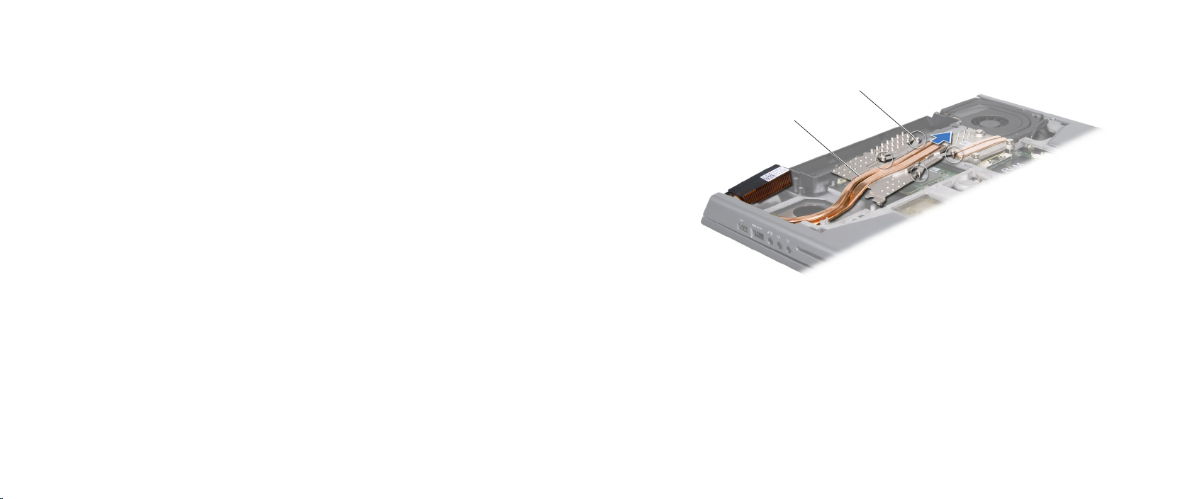
In sequential order (indicated on the graphics card heat sink), loosen the 9.
four captive screws that secure the graphics card heat sink to the graphics
card.
Slide and lift the graphics card heat sink o the computer base.10.
CHAPTER 15: GRAPHICS CARD HEAT SINK
1 captive screws (4) 2 graphics card heat sink
065
/
065
Page 66

Replacing the Graphics Card Heat Sink
Follow the instructions in “Before You Begin” on page 1. 6.
Place the graphics card heat sink in the computer base. 2.
Align the four captive screws on the graphics card heat sink with the screw 3.
holes on the graphics card and tighten the screws in sequential order
(indicated on the graphics card heat sink).
Replace the graphics card fan (see “Replacing the Graphics Card Fan” on 4.
page 62).
Replace the left air-vent (see “Replacing the Air Vents” on page 5. 43).
Replace the center control cover (see “Replacing the Center Control Cover” 6.
on page 31).
Replace the memory module(s) (see “Replacing the Memory Module(s)” on 7.
page 23).
Replace the hard drive (see “Replacing the Hard Drive” on page 8. 18).
Replace the compartment door (see “Replacing the Compartment Door” on 9.
page 14).
Replace the battery pack (see “Replacing the Battery Pack” on page 10. 11).
CAUTION: Before turning on the computer, replace all screws and
ensure that no stray screws remain inside the computer. Failure to do
so may result in damage to the computer.
CHAPTER 15: GRAPHICS CARD HEAT SINK
066
/
066
Page 67

CHAPTER 16: GRAPHICS CARD
CHAPTER 16: GRAPHICS CARD
CHAPTER 16: GRAPHICS CARD
067
/
067
Page 68

Graphics Card
WARNING: Before working inside your computer, read the safety
information that shipped with your computer. For additional safety
best practices information, see the Regulatory Compliance Homepage
at www.dell.com/regulatory_compliance.
WARNING: Before performing these procedures, turn o the computer,
disconnect the AC adapter from the electrical outlet and the computer,
disconnect the modem from the wall connector and the computer, and
remove any other external cables from the computer.
CAUTION: Only a certied service technician should perform repairs on
your computer. Damage due to servicing that is not authorized by Dell™
is not covered by your warranty.
CAUTION: To avoid electrostatic discharge, ground yourself by using a
wrist grounding strap or by periodically touching an unpainted metal
surface (such as a connector on the back of the computer).
CAUTION: To help prevent damage to the system board, remove the
main battery (see “Removing the Battery Pack” on page 11) before
working inside the computer.
CHAPTER 16: GRAPHICS CARD
068
/
068
Page 69
1
2
Removing the Graphics Card
Follow the instructions in “Before You Begin” on page 1. 6.
Remove the battery pack (see “Removing the Battery Pack” on page 2. 11).
Remove the compartment door (see “Removing the Compartment Door” on 3.
page 14).
Remove the hard drive (see “Removing the Hard Drive” on page 4. 17).
Remove the memory module(s) (see “Removing the Memory Module(s)” on 5.
page 21).
Remove the center control cover (see “Removing the Center Control Cover” 6.
on page 30).
Remove the left air-vent (see “Removing the Air Vents” on page 7. 42).
Remove the graphics card fan (see “Removing the Graphics Card Fan” on 8.
page 61).
Remove the graphics card heat sink (see “Removing the Graphics Card Heat 9.
Sink” on page 65).
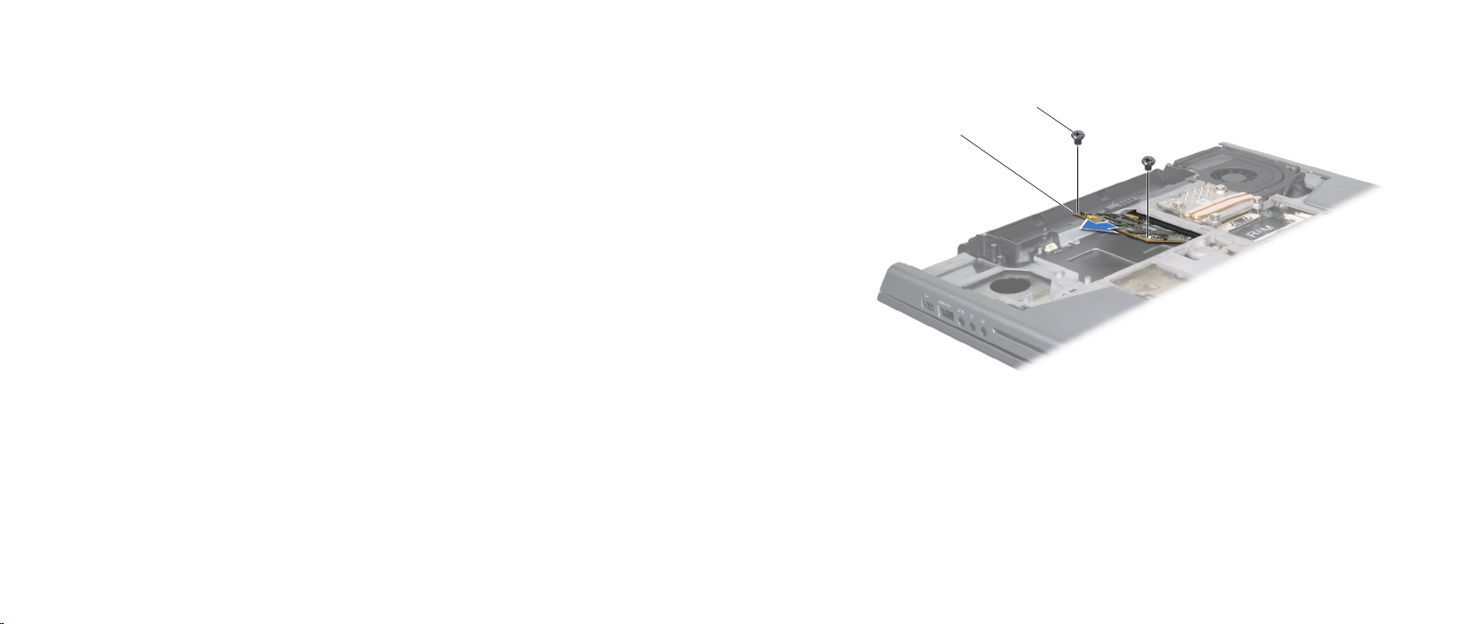
Remove the two screws that secure the graphics card to the system board.10.
Remove the graphics card from the system board connector.11.
CHAPTER 16: GRAPHICS CARD
1 screws (2) 2 graphics card
069
/
069
Page 70

Replacing the Graphics Card
Follow the instructions in “Before You Begin” on page 1. 6.
Insert the graphics card at a 45-degree angle into the system board 2.
connector.
Replace the two screws that secure the graphics card to the system board.3.
Replace the graphics card heat sink (see “Replacing the Graphics Card Heat 4.
Sink” on page 66).
Replace the graphics card fan (see “Replacing the Graphics Card Fan” on 5.
page 62).
Replace the left air-vent (see “Replacing the Air Vents” on page 6. 43).
Replace the center control cover (see “Replacing the Center Control Cover” 7.
on page 31).
Replace the memory module(s) (see “Replacing the Memory Module(s)” on 8.
page 23).
Replace the hard drive (see “Replacing the Hard Drive” on page 9. 18).
Replace the compartment door (see “Replacing the Compartment Door” on 10.
page 14).
Replace the battery pack (see “Replacing the Battery Pack” on page 11. 11).
CAUTION: Before turning on the computer, replace all screws and
ensure that no stray screws remain inside the computer. Failure to do
so may result in damage to the computer.
CHAPTER 16: GRAPHICS CARD
070
/
070
Page 71

CHAPTER 17: DISPLAY
CHAPTER 17: DISPLAY
CHAPTER 17: DISPLAY
071
/
071
Page 72

Display
WARNING: Before working inside your computer, read the safety
information that shipped with your computer. For additional safety
best practices information, see the Regulatory Compliance Homepage
at www.dell.com/regulatory_compliance.
WARNING: Before performing these procedures, turn o the computer,
disconnect the AC adapter from the electrical outlet and the computer,
disconnect the modem from the wall connector and the computer, and
remove any other external cables from the computer.
CAUTION: Only a certied service technician should perform repairs on
your computer. Damage due to servicing that is not authorized by Dell™
is not covered by your warranty.
CAUTION: To avoid electrostatic discharge, ground yourself by using a
wrist grounding strap or by periodically touching an unpainted metal
surface (such as a connector on the back of the computer).
CAUTION: To help prevent damage to the system board, remove the
main battery (see “Removing the Battery Pack” on page 11) before
working inside the computer.
CAUTION: To avoid damage to the display, you must not disassemble
your Edge-to-Edge display assembly in the eld.
CHAPTER 17: DISPLAY
072
/
072
Page 73
Display Assembly
Removing the Display Assembly
Follow the instructions in “Before You Begin” on page 1. 6.
Remove the battery pack (see “Removing the Battery Pack” on page 2. 11).
Remove the compartment door (see “Removing the Compartment Door” on 3.
page 14).
Remove the hard drive (see “Removing the Hard Drive” on page 4. 17).
Remove the memory module(s) (see “Removing the Memory Module(s)” on 5.
page 21).
Remove the center control cover (see “Removing the Center Control Cover” 6.
on page 30).
Remove the keyboard (see “Removing the Keyboard” on page 7. 34).
Remove the palm rest (see “Removing the Palm Rest” on page 8. 38).
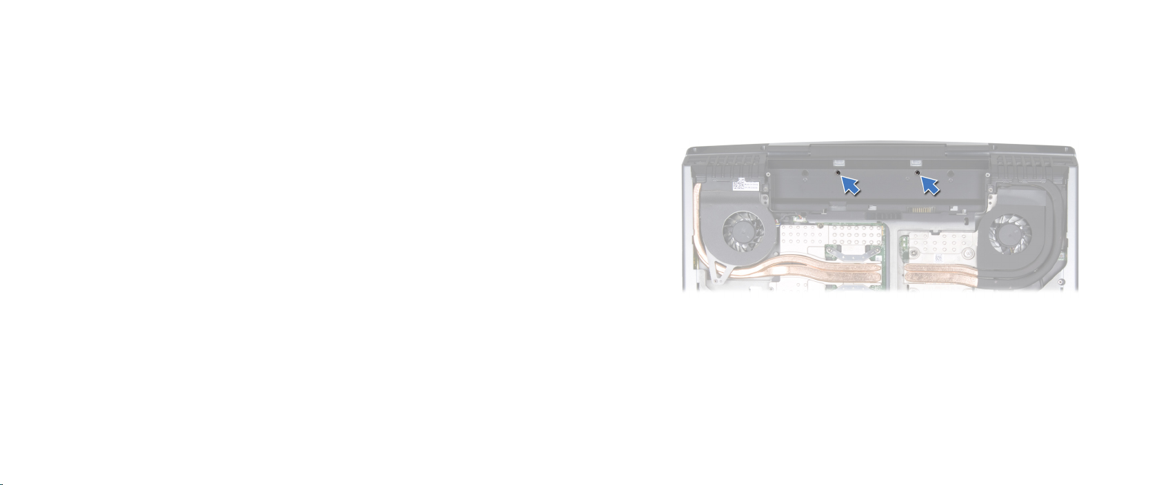
Remove the two screws from the battery bay.9.
Turn the computer top side up and open the display as far as possible.10.
CHAPTER 17: DISPLAY
073
/
073
Page 74
1
2
3
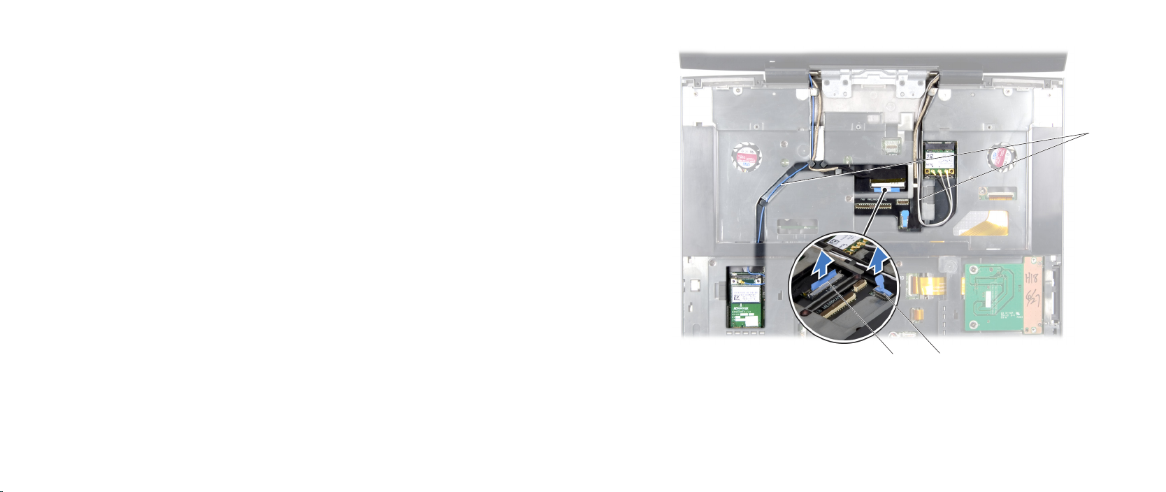
Disconnect the antenna cables from the respective Mini-Cards and remove 11.
these cables from their routing guides.
Disconnect the display cable and the camera cable from the respective 12.
system board connectors, and remove these cables from their routing
guides.
CHAPTER 17: DISPLAY
1 Mini-Card antenna cables 3 display cable connector
2 camera cable connector
074
/
074
Page 75
CHAPTER 17: DISPLAY
1
2
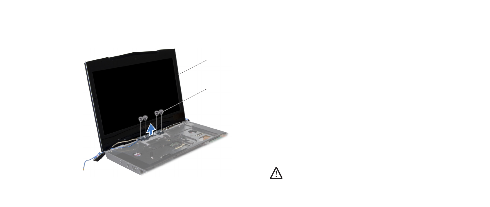
Remove the four screws (two from each hinge) that secure the display 13.
assembly to the computer base.
Tilt the display assembly towards the computer base at a 45-degree angle 14.
and lift the display assembly o the computer.
1 display assembly 2 screws (4)
Replacing the Display Assembly
Follow the instructions in “Before You Begin” on page 1. 6.
Align the screw holes on the display hinges with the screw holes on the 2.
computer base.
Replace the four screws (two on each hinge) that secure the display 3.
assembly to the computer base.
Route the Mini-Card antenna cables through the routing guides and 4.
connect them to the respective Mini-Cards.
Route the display and camera cables through the routing guides and 5.
connect them to the system board connectors.
Replace the two screws in the battery bay.6.
Replace the palm rest (see “Replacing the Palm Rest” on page 7. 39).
Replace the keyboard (see “Replacing the Keyboard” on page 8. 35).
Replace the center control cover (see “Replacing the Center Control Cover” 9.
on page 31).
Replace the memory module(s) (see “Replacing the Memory Module(s)” on 10.
page 23).
Replace the hard drive (see “Replacing the Hard Drive” on page 11. 18).
Replace the compartment door (see “Replacing the Compartment Door” on 12.
page 14).
Replace the battery pack (see “Replacing the Battery Pack” on page 13. 8).
CAUTION: Before turning on the computer, replace all screws and
ensure that no stray screws remain inside the computer. Failure to do
so may result in damage to the computer.
075
/
075
Page 76
CHAPTER 17: DISPLAY
1
2
3
Display Hinge Cover
Removing the Display Hinge Cover
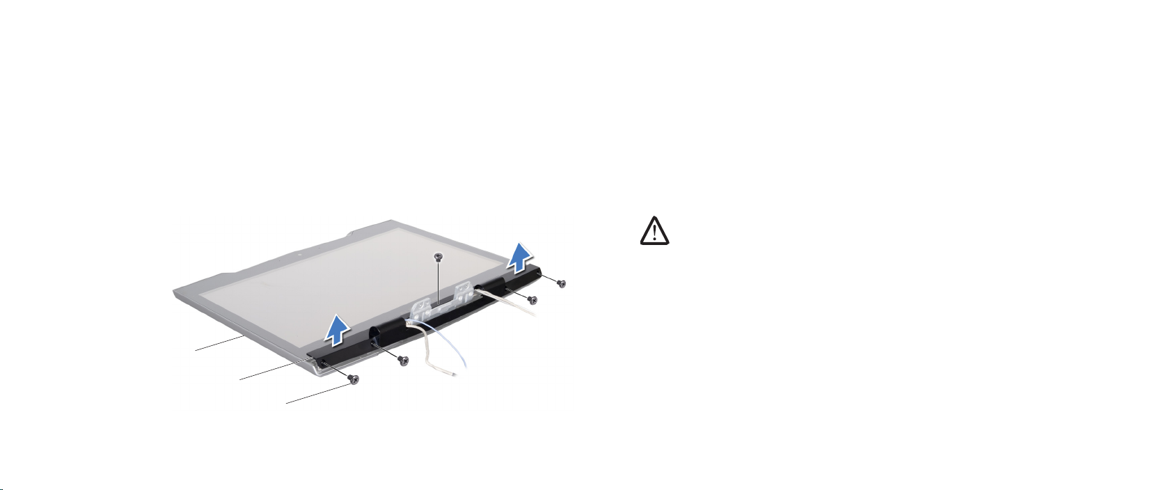
Follow the instructions in “Before You Begin” on page 1. 6.
Remove the display assembly (see “Removing the Display Assembly” on 2.
page 73).
Remove the ve screws that secure the display hinge cover to the display 3.
assembly.
Pry the display hinge cover up with a plastic scribe.4.
1 screws (5) 3 display assembly
2 display hinge cover
Replacing the Display Hinge Cover
Follow the instructions in “Before You Begin” on page 1. 6.
Route the antenna, display, and camera cables through the display hinge 2.
cover.
Align the screw holes on the display hinge cover with the display back cover.3.
Replace the ve screws that secure the display hinge cover to the display 4.
assembly.
Replace the display assembly (see “Replacing the Display Assembly” on 5.
page 75).
CAUTION: Before turning on the computer, replace all screws and
ensure that no stray screws remain inside the computer. Failure to do
so may result in damage to the computer.
076
/
076
Page 77
Display Panel
2
3
4
1
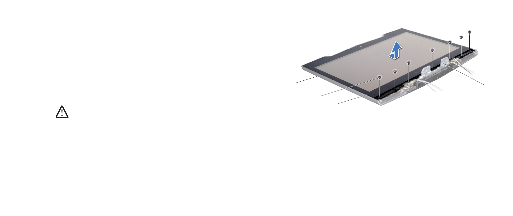
Removing the Display Panel
Follow the instructions in “Before You Begin” on page 1. 6.
Remove the display assembly (see “Removing the Display Assembly” on 2.
page 73).
Remove the display hinge cover (see “Removing the Display Hinge Cover” on 3.
page 76).
Remove the seven screws that secure the display panel to the display back 4.
cover.
NOTE: Use a dry, lint-free, soft cloth while removing or replacing the
display panel, to avoid smudging the display panel.
Slide the display panel towards the display hinges, to release it from the 5.
display back cover.
Lift the display panel up and move it towards the top of the display back 6.
cover.
CHAPTER 17: DISPLAY
1 display hinges (2) 3 screws (7)
2 display panel 4 display back cover
077
/
077
Page 78
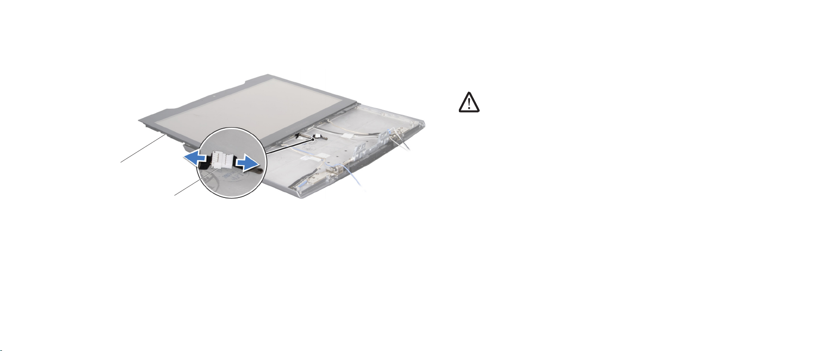
CHAPTER 17: DISPLAY
2
1
Disconnect the AlienHead cable connector and lift the display panel o the 7.
display back cover.
Replacing the Display Panel
Follow the instructions in “Before You Begin” on page 1. 6.
Connect the AlienHead cable to the connector.2.
NOTE: Use a dry, lint-free, soft cloth while removing or replacing the
display panel, to avoid smudging the display panel.
Replace the display panel and slide the display panel towards the top of the 3.
display back cover.
Replace the seven screws that secure the display panel to the display back 4.
cover.
Replace the display hinge cover (see “Replacing the Display Hinge Cover” on 5.
page 76).
Replace the display assembly (see “Replacing the Display Assembly” on 6.
page 75).
1 AlienHead cable connector 2 display panel
078
/
078
Page 79
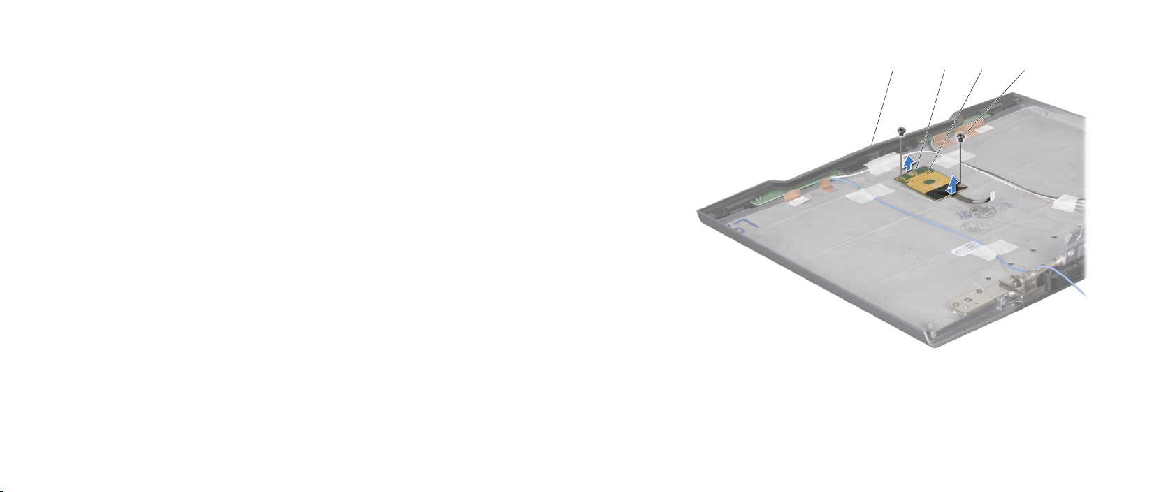
1
2
34
AlienHead Board
Removing the AlienHead Board
Follow the instructions in “Before You Begin” on page 1. 6.
Remove the display assembly (see “Removing the Display Assembly” on 2.
page 73).
Remove the display hinge cover (see “Removing the Display Hinge Cover” on 3.
page 76).
Remove the display panel (see “Removing the Display Panel” on page 4. 77).
Remove the two screws that secure the AlienHead board to the display back 5.
cover.
Lift the top of the AlienHead board to release it from the tabs that hold it in 6.
place.
Slide the AlienHead board down and lift it o the display back cover.7.
CHAPTER 17: DISPLAY
1 screws (2) 3 top of the AlienHead board
2 tabs (2) 4 display back cover
079
/
079
Page 80

Replacing the AlienHead Board
Follow the instructions in “Before You Begin” on page 1. 6.
Align the AlienHead board with the tabs on the display back cover. Gently 2.
press and slide the AlienHead board into place.
Replace the two screws that secure the AlienHead board to the display back 3.
cover.
Replace the display panel (see “Replacing the Display Panel” on page 4. 78).
Replace the display hinge cover (see “Replacing the Display Hinge Cover” on 5.
page 76).
Replace the display assembly (see “Replacing the Display Assembly” on 6.
page 75).
CAUTION: Before turning on the computer, replace all screws and
ensure that no stray screws remain inside the computer. Failure to do
so may result in damage to the computer.
CHAPTER 17: DISPLAY
080
/
080
Page 81

CHAPTER 18: MAGNESIUM COVER
CHAPTER 18: MAGNESIUM COVER
CHAPTER 18: MAGNESIUM COVER
081
/
081
Page 82

Magnesium Cover
WARNING: Before working inside your computer, read the safety
information that shipped with your computer. For additional safety
best practices information, see the Regulatory Compliance Homepage
at www.dell.com/regulatory_compliance.
WARNING: Before performing these procedures, turn o the computer,
disconnect the AC adapter from the electrical outlet and the computer,
disconnect the modem from the wall connector and the computer, and
remove any other external cables from the computer.
CAUTION: Only a certied service technician should perform repairs on
your computer. Damage due to servicing that is not authorized by Dell™
is not covered by your warranty.
CAUTION: To avoid electrostatic discharge, ground yourself by using a
wrist grounding strap or by periodically touching an unpainted metal
surface (such as a connector on the back of the computer).
CAUTION: To help prevent damage to the system board, remove the
main battery (see “Removing the Battery Pack” on page 11) before
working inside the computer.
CHAPTER 18: MAGNESIUM COVER
082
/
082
Page 83
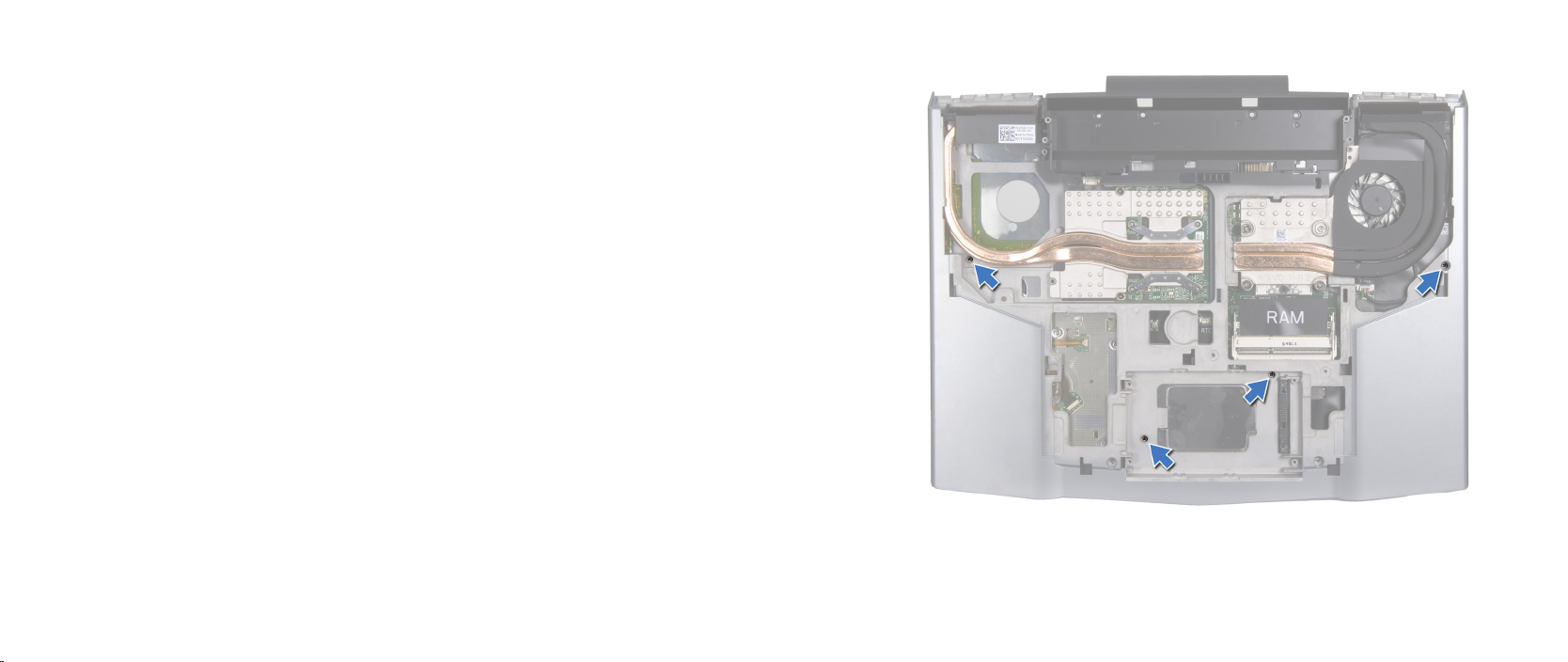
Removing the Magnesium Cover
Follow the instructions in “Before You Begin” on page 1. 6.
Remove the battery pack (see “Removing the Battery Pack” on page 2. 11).
Remove the compartment door (see “Removing the Compartment Door” on 3.
page 14).
Remove the hard drive (see “Removing the Hard Drive” on page 4. 17).
Remove the memory module(s) (see “Removing the Memory Module(s)” on 5.
page 21).
Remove the graphics card fan (see “Removing the Graphics Card Fan” on 6.
page 61).
Remove the four screws that secure the magnesium cover to the computer 7.
base.
CHAPTER 18: MAGNESIUM COVER
083
/
083
Page 84
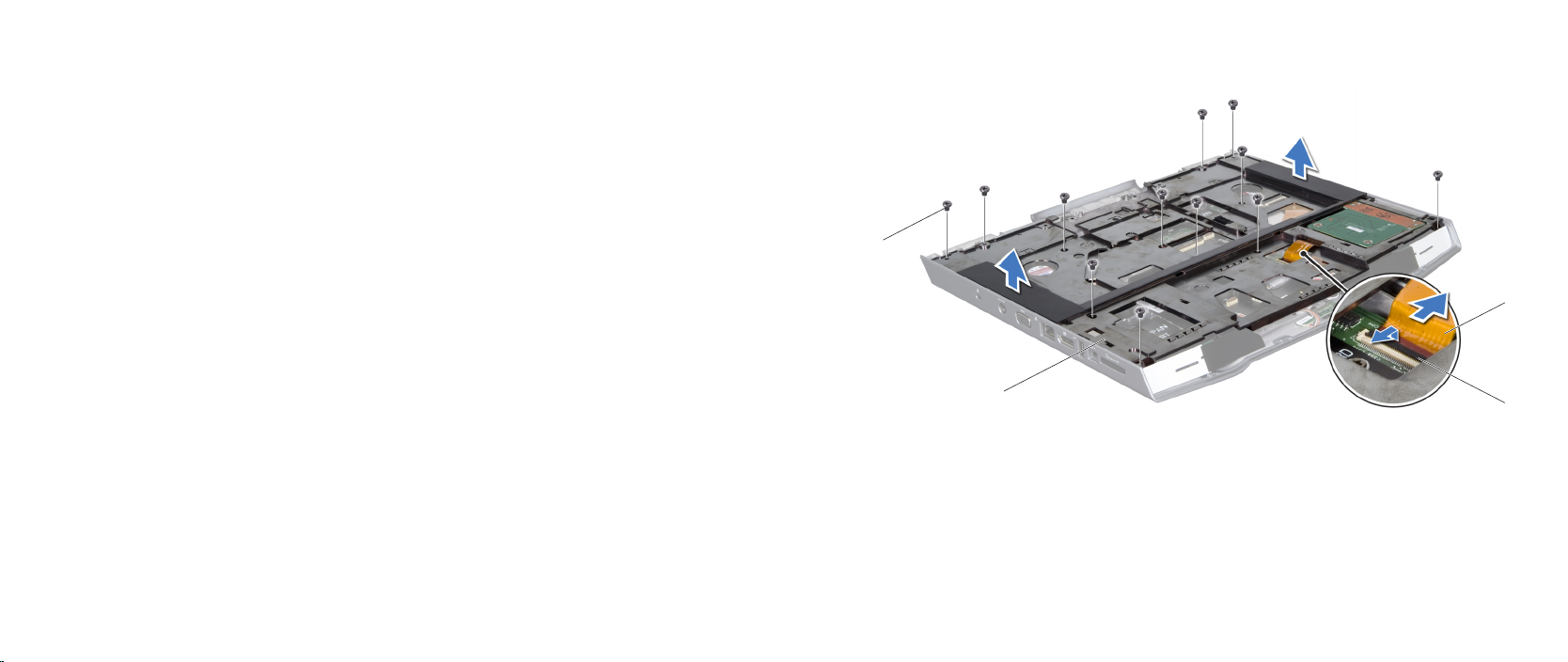
3
4
1
2
Remove the center control cover (see “Removing the Center Control Cover” 8.
on page 30).
Remove the keyboard (see “Removing the Keyboard” on page 9. 34).
Remove the palm rest (see “Removing the Palm Rest” on page 10. 38).
Remove the display assembly (see “Removing the Display Assembly” on 11.
page 73).
Release the ExpressCard connector latch and disconnect the ExpressCard 12.
cable from the system board connector.
Press and eject any installed cards from the ExpressCard slot and the 8-in-1 13.
Media Card Reader before removing the magnesium cover.
Remove the twelve screws that secure the magnesium cover to the 14.
computer base.
Lift the magnesium cover o the computer.15.
CHAPTER 18: MAGNESIUM COVER
1 ExpressCard cable 3 magnesium cover
2 ExpressCard connector latch 4 screws (12)
084
/
084
Page 85

CHAPTER 18: MAGNESIUM COVER
Replacing the Magnesium Cover
Follow the instructions in “Before You Begin” on page 1. 6.
Replace the magnesium cover on the computer base.2.
Replace the twelve screws that secure the magnesium cover to the 3.
computer base.
Replace any cards that were ejected from the ExpressCard slot and the 4.
8-in-1 Media Card Reader.
Connect the ExpressCard cable to the system board connector and push 5.
down the ExpressCard connector latch to secure the ExpressCard cable.
Replace the display assembly (see “Replacing the Display Assembly” on 6.
page 75).
Replace the palm rest (see “Replacing the Palm Rest” on page 7. 39).
Replace the keyboard (see “Replacing the Keyboard” on page 8. 35).
Replace the center control cover (see “Replacing the Center Control Cover” 9.
on page 31).
Replace the four screws that secure the magnesium cover to the computer 10.
base.
Replace the graphics card fan (see “Replacing the Graphics Card Fan” on 11.
page 62).
Replace the memory module(s) (see “Replacing the Memory Module(s)” on 12.
page 23).
Replace the hard drive (see “Replacing the Hard Drive” on page 13. 18).
Replace the compartment door (see “Replacing the Compartment Door” on 14.
page 14).
Replace the battery pack (see “Replacing the Battery Pack” on page 15. 11).
CAUTION: Before turning on the computer, replace all screws and
ensure that no stray screws remain inside the computer. Failure to do
so may result in damage to the computer.
085
/
085
Page 86

CHAPTER 19: INPUT/OUTPUT BOARD
CHAPTER 19: INPUT/OUTPUT BOARD
CHAPTER 19: INPUT/OUTPUT BOARD
086
/
086
Page 87

Input/Output Board
WARNING: Before working inside your computer, read the safety
information that shipped with your computer. For additional safety
best practices information, see the Regulatory Compliance Homepage
at www.dell.com/regulatory_compliance.
WARNING: Before performing these procedures, turn o the computer,
disconnect the AC adapter from the electrical outlet and the computer,
disconnect the modem from the wall connector and the computer, and
remove any other external cables from the computer.
CAUTION: Only a certied service technician should perform repairs on
your computer. Damage due to servicing that is not authorized by Dell™
is not covered by your warranty.
CAUTION: To avoid electrostatic discharge, ground yourself by using a
wrist grounding strap or by periodically touching an unpainted metal
surface (such as a connector on the back of the computer).
CAUTION: To help prevent damage to the system board, remove the
main battery (see “Removing the Battery Pack” on page 11) before
working inside the computer.
CHAPTER 19: INPUT/OUTPUT BOARD
087
/
087
Page 88
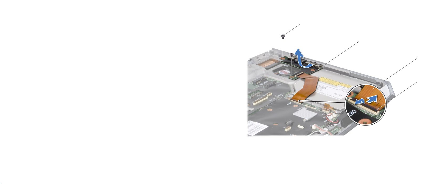
1
2
4
3
Removing the Input/Output Board
Follow the instructions in “Before You Begin” on page 1. 6.
Remove the battery pack (see “Removing the Battery Pack” on page 2. 11).
Remove the compartment door (see “Removing the Compartment Door” on 3.
page 14).
Remove the hard drive (see “Removing the Hard Drive” on page 4. 17).
Remove the memory module(s) (see “Removing the Memory Module(s)” on 5.
page 21).
Remove the center control cover (see “Removing the Center Control Cover” 6.
on page 30).
Remove the keyboard (see “Removing the Keyboard” on page 7. 34).
Remove the palm rest (see “Removing the Palm Rest” on page 8. 38).
Remove the display assembly (see “Removing the Display Assembly” on 9.
page 73).
Remove the magnesium cover (see “Removing the Magnesium Cover” on 10.
page 83).
Release the audio cable connector latch to disconnect the audio cable from 11.
the system board connector.
Remove the two screws that secure the input/output board to the computer 12.
base.
Tilt the input/output board at an angle and lift it out of the computer base.13.
CHAPTER 19: INPUT/OUTPUT BOARD
1 audio cable connector latch 3 input/output board
2 audio cable 4 screws (2)
088
/
088
Page 89

CHAPTER 19: INPUT/OUTPUT BOARD
Replacing the Input/Output Board
Follow the instructions in “Before You Begin” on page 1. 6.
Align the connectors on the input/output board with the slots on the 2.
computer.
Replace the two screws that secure the input/output board to the computer 3.
base.
Connect the audio cable to the system board connector and push down the 4.
audio cable connector latch to secure the audio cable.
Replace the magnesium cover (see “Replacing the Magnesium Cover” on 5.
page 85).
Replace the display assembly (see “Replacing the Display Assembly” on page 6.
75).
Replace the palm rest (see “Replacing the Palm Rest” on page 7. 39).
Replace the keyboard (see “Replacing the Keyboard” on page 8. 35).
Replace the center control cover (see “Replacing the Center Control Cover” 9.
on page 31).
Replace the memory module(s) (see “Replacing the Memory Module(s)” on 10.
page 23).
Replace the hard drive (see “Replacing the Hard Drive” on page 11. 18).
Replace the compartment door (see “Replacing the Compartment Door” on 12.
page 14).
Replace the battery pack (see “Replacing the Battery Pack” on page 13. 11).
CAUTION: Before turning on the computer, replace all screws and
ensure that no stray screws remain inside the computer. Failure to do
so may result in damage to the computer.
089
/
089
Page 90

CHAPTER 20: CONSUMER IR BOARD
CHAPTER 20: CONSUMER IR BOARD
CHAPTER 20: CONSUMER IR BOARD
090
/
090
Page 91

Consumer IR Board
WARNING: Before working inside your computer, read the safety
information that shipped with your computer. For additional safety
best practices information, see the Regulatory Compliance Homepage
at www.dell.com/regulatory_compliance.
WARNING: Before performing these procedures, turn o the computer,
disconnect the AC adapter from the electrical outlet and the computer,
disconnect the modem from the wall connector and the computer, and
remove any other external cables from the computer.
CAUTION: Only a certied service technician should perform repairs on
your computer. Damage due to servicing that is not authorized by Dell™
is not covered by your warranty.
CAUTION: To avoid electrostatic discharge, ground yourself by using a
wrist grounding strap or by periodically touching an unpainted metal
surface (such as a connector on the back of the computer).
CAUTION: To help prevent damage to the system board, remove the
main battery (see “Removing the Battery Pack” on page 11) before
working inside the computer.
CHAPTER 20: CONSUMER IR BOARD
091
/
091
Page 92
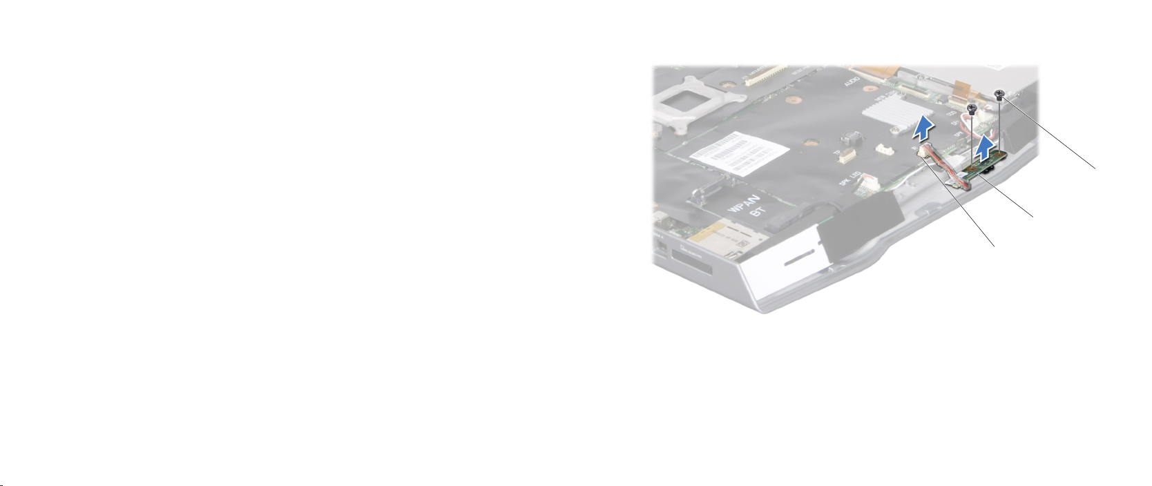
1
2
3
Removing the Consumer IR Board
Follow the instructions in “Before You Begin” on page 1. 6.
Remove the battery pack (see “Removing the Battery Pack” on page 2. 11).
Remove the compartment door (see “Removing the Compartment Door” on 3.
page 14).
Remove the hard drive (see “Removing the Hard Drive” on page 4. 17).
Remove the memory module(s) (see “Removing the Memory Module(s)” on 5.
page 21).
Remove the center control cover (see “Removing the Center Control Cover” 6.
on page 30).
Remove the keyboard (see “Removing the Keyboard” on page 7. 34).
Remove the palm rest (see “Removing the Palm Rest” on page 8. 38).
Remove the display assembly (see “Removing the Display Assembly” on 9.
page 73).
Remove the magnesium cover (see “Removing the Magnesium Cover” on 10.
page 83).
Disconnect the consumer IR board cable from the system board connector.11.
Remove the two screws that secure the consumer IR board to the computer 12.
base.
Lift the consumer IR board o the computer base. 13.
CHAPTER 20: CONSUMER IR BOARD
1 screws (2) 3 consumer IR board connector
2 consumer IR board
092
/
092
Page 93

CHAPTER 20: CONSUMER IR BOARD
Replacing the Consumer IR Board
Follow the instructions in “Before You Begin” on page 1. 6.
Align the consumer IR board with the guide posts on the computer base.2.
Replace the two screws that secure the consumer IR board to the computer 3.
base.
Connect the consumer IR board cable to the system board connector.4.
Replace the magnesium cover (see “Replacing the Magnesium Cover” on 5.
page 85).
Replace the display assembly (see “Replacing the Display Assembly” on page 6.
75).
Replace the palm rest (see “Replacing the Palm Rest” on page 7. 39).
Replace the keyboard (see “Replacing the Keyboard” on page 8. 35).
Replace the center control cover (see “Replacing the Center Control Cover” 9.
on page 31).
Replace the memory module(s) (see “Replacing the Memory Module(s)” on 10.
page 23).
Replace the hard drive (see “Replacing the Hard Drive” on page 11. 18).
Replace the compartment door (see “Replacing the Compartment Door” on 12.
page 14).
Replace the battery pack (see “Replacing the Battery Pack” on page 13. 11).
CAUTION: Before turning on the computer, replace all screws and
ensure that no stray screws remain inside the computer. Failure to do
so may result in damage to the computer.
093
/
093
Page 94

CHAPTER 21: OPTICAL DRIVE
CHAPTER 21: OPTICAL DRIVE
CHAPTER 21: OPTICAL DRIVE
094
/
094
Page 95

Optical Drive
WARNING: Before working inside your computer, read the safety
information that shipped with your computer. For additional safety
best practices information, see the Regulatory Compliance Homepage
at www.dell.com/regulatory_compliance.
WARNING: Before performing these procedures, turn o the computer,
disconnect the AC adapter from the electrical outlet and the computer,
disconnect the modem from the wall connector and the computer, and
remove any other external cables from the computer.
CAUTION: Only a certied service technician should perform repairs on
your computer. Damage due to servicing that is not authorized by Dell™
is not covered by your warranty.
CAUTION: To avoid electrostatic discharge, ground yourself by using a
wrist grounding strap or by periodically touching an unpainted metal
surface (such as a connector on the back of the computer).
CAUTION: To help prevent damage to the system board, remove the
main battery (see “Removing the Battery Pack” on page 11) before
working inside the computer.
CHAPTER 21: OPTICAL DRIVE
095
/
095
Page 96
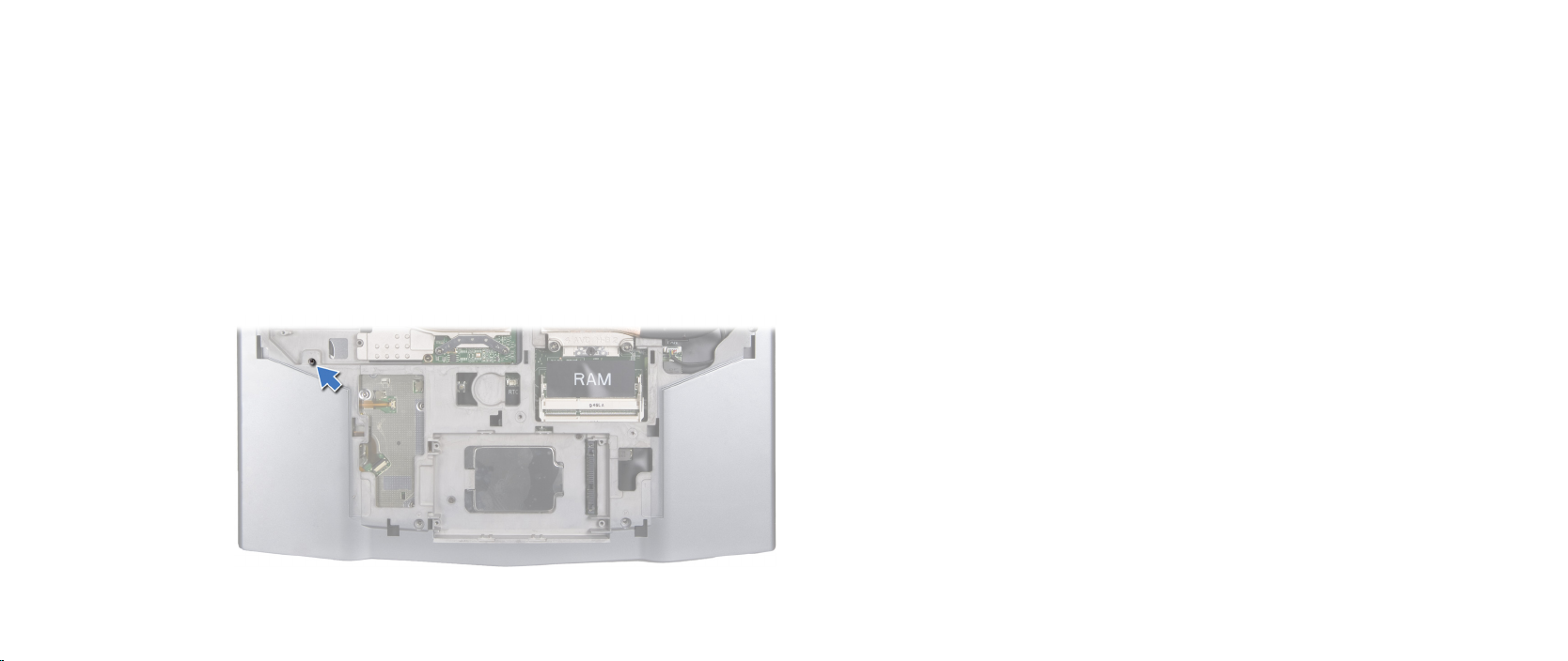
CHAPTER 21: OPTICAL DRIVE
Removing the Optical Drive
Follow the instructions in “Before You Begin” on page 1. 6.
Remove the battery pack (see “Removing the Battery Pack” on page 2. 11).
Remove the compartment door (see “Removing the Compartment Door” on 3.
page 14).
Remove the hard drive (see “Removing the Hard Drive” on page 4. 17).
Remove the memory module(s) (see “Removing the Memory Module(s)” on 5.
page 21).
Remove the screw that secures the optical drive to the computer base.6.
Remove the center control cover (see “Removing the Center Control Cover” 7.
on page 30).
Remove the keyboard (see “Removing the Keyboard” on page 8. 34).
Remove the palm rest (see “Removing the Palm Rest” on page 9. 38).
Remove the display assembly (see “Removing the Display Assembly” on 10.
page 73).
Remove the magnesium cover (see “Removing the Magnesium Cover” on 11.
page 83).
Remove the input/output board (see “Removing the Input/Output Board” on 12.
page 88).
096
/
096
Page 97
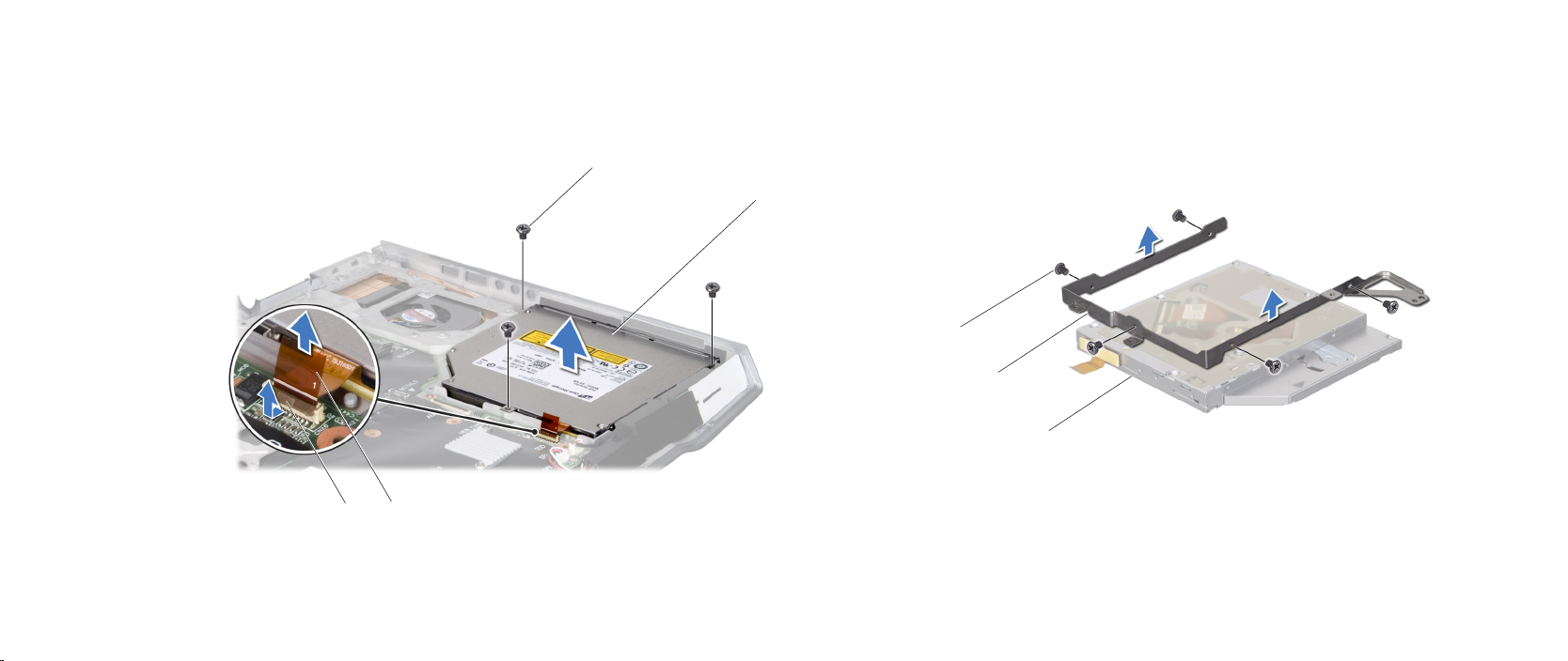
CHAPTER 21: OPTICAL DRIVE
2
3
1
1
2
3
4
Remove the three screws that secure the optical drive to the computer base.13.
Release the connector latch and disconnect the optical-drive cable from the 14.
Remove the ve screws that secure the optical drive to the optical-drive 16.
bracket and lift the optical-drive bracket out.
system board connector.
Lift the optical drive out of the computer.15.
1 screws (3) 3 optical-drive cable
2 optical drive 4 connector latch
1 optical drive 3 screws (5)
2 optical-drive bracket
097
/
097
Page 98

CHAPTER 21: OPTICAL DRIVE
1
2
Disconnect the optical-drive cable from the optical drive.17.
1 optical drive 2 optical-drive cable
098
/
098
Page 99

CHAPTER 21: OPTICAL DRIVE
Replacing the Optical Drive
Follow the instructions in “Before You Begin” on page 1. 6.
Connect the optical-drive cable to the optical drive. 2.
Replace the ve screws that secure the optical drive to the optical-drive 3.
bracket.
Place the optical drive in the computer base.4.
Slide the optical-drive cable into the system board connector and push 5.
down the connector latch to secure the cable to the connector.
Replace the three screws that secure the optical drive to the computer base.6.
Replace the input/output board (see “Replacing the Input/Output Board” on 7.
page 89).
Replace the display assembly (see “Replacing the Display Assembly” on page 8.
75).
Replace the magnesium cover (see “Replacing the Magnesium Cover” on 9.
page 85).
Replace the palm rest (see “Replacing the Palm Rest” on page 10. 39).
Replace the keyboard (see “Replacing the Keyboard” on page 11. 35).
Replace the center control cover (see “Replacing the Center Control Cover” 12.
on page 31).
Replace the screw that secures the optical drive to the computer base.13.
Replace the memory module(s) (see “Replacing the Memory Module(s)” on 14.
page 23).
Replace the hard drive (see “Replacing the Hard Drive” on page 15. 18).
Replace the compartment door (see “Replacing the Compartment Door” on 16.
page 14).
Replace the battery pack (see “Replacing the Battery Pack” on page 17. 11).
CAUTION: Before turning on the computer, replace all screws and
ensure that no stray screws remain inside the computer. Failure to do
so may result in damage to the computer.
099
/
099
Page 100

CHAPTER 22: SYSTEM BOARD
CHAPTER 22: SYSTEM BOARD
CHAPTER 22: SYSTEM BOARD
e system board’s BIOS chip contains the Service Tag, which is also visible on a
barcode label on the bottom of the computer. e Service Tag has to be entered
in the replacement system board’s BIOS chip using the System Setup utility.
0100
/
0100
 Loading...