

Page 1

Configuring VLAN Settings in Lifecycle
Controller for Dell PowerEdge Servers
This Dell Technical White Paper provides detailed information about configuring VLAN settings on a network port using Lifecycle
Controller on the Dell 12th generation servers and later versions.
Dell Engineering
October 2013
Sanjeev Nayaka
Raghavendra Venkataramudu
Revisions
1 Configuring VLAN Settings in Lifecycle Controller for Dell PowerEdge Servers
Page 2

Date Description
October 2013 Initial release
THIS WHITE PAPER IS FOR INFORMATIONAL PURPOSES ONLY, AND MAY CONTAIN TYPOGRAPHICAL ERRORS AND
TECHNICAL INACCURACIES. THE CONTENT IS PROVIDED AS-IS, WITHOUT EXPRESS OR IMPLIED WARRANTIES OF
ANY KIND.
© 2013 Dell Inc. All rights reserved. Reproduction of this material in any manner whatsoever without the express
written permission of Dell Inc. is strictly forbidden. For more information, contact Dell.
Dell, the DELL logo, and the DELL badge are trademarks of Dell Inc. Symantec, NetBackup, and Backup Exec are
trademarks of Symantec Corporation in the U.S. and other countries. Microsoft, Windows, and Windows Server are
registered trademarks of Microsoft Corporation in the United States and/or other countries. Other trademarks and
trade names may be used in this document to refer to either the entities claiming the marks and names or their
products. Dell disclaims any proprietary interest in the marks and names of others.
Performance of network reference architectures discussed in this document may vary with differing deployment
conditions, network loads, and the like. Third party products may be included in reference architectures for the
convenience of the reader. Inclusion of such third-party products does not necessarily constitute Dell’s
recommendation of those products. Please consult your Dell representative for additional information.
Trademarks used in this text:
Dell™, the Dell logo, Dell Boomi™, Dell Precision™ ,OptiPlex™, Latitude™, PowerEdge™, PowerVault™,
PowerConnect™, OpenManage™, EqualLogic™, Compellent™, KACE™, FlexAddress™, Force10™ and Vostro™ are
trademarks of Dell Inc. Other Dell trademarks may be used in this document. Cisco Nexus®, Cisco MDS
®
0S
, and other Cisco Catalyst® are registered trademarks of Cisco System Inc. EMC VNX®, and EMC Unisphere® are
registered trademarks of EMC Corporation. Intel
Intel Corporation in the U.S. and other countries. AMD
Phenom™ and AMD Sempron™ are trademarks of Advanced Micro Devices, Inc. Microsoft
®
Server
, Internet Explorer®, MS-DOS®, Windows Vista® and Active Directory® are either trademarks or registered
trademarks of Microsoft Corporation in the United States and/or other countries. Red Hat
®
Linux
are registered trademarks of Red Hat, Inc. in the United States and/or other countries. Novell® and SUSE® are
registered trademarks of Novell Inc. in the United States and other countries. Oracle
Oracle Corporation and/or its affiliates. Citrix
trademarks of Citrix Systems, Inc. in the United States and/or other countries. VMware
vCenter
countries. IBM
NetXtreme
®
and vSphere® are registered trademarks or trademarks of VMware, Inc. in the United States or other
®
is a registered trademark of International Business Machines Corporation. Broadcom® and
®
are registered trademarks of Broadcom Corporation. Qlogic is a registered trademark of QLogic
®
, Pentium®, Xeon®, Core® and Celeron® are registered trademarks of
®
is a registered trademark and AMD Opteron™, AMD
®
, Xen®, XenServer® and XenMotion® are either registered trademarks or
®
, Windows®, Windows
®
and Red Hat® Enterprise
®
is a registered trademark of
®
, Virtual SMP®, vMotion®,
®
, Cisco NX-
Corporation. Other trademarks and trade names may be used in this document to refer to either the entities claiming
the marks and/or names or their products and are the property of their respective owners. Dell disclaims proprietary
interest in the marks and names of others.
2 Configuring VLAN Settings in Lifecycle Controller for Dell PowerEdge Servers
Page 3

Contents
Revisions .................................................................................................................................................................................................. 1
Introduction ........................................................................................................................................................................................... 4
1 Network Setup for LC GUI with VLAN Settings ....................................................................................................................... 5
1.1 Configuring VLAN Settings in LC GUI—Process Flow Chart .................................................................................... 6
1.2 Configuring VLAN Settings in LC GUI ............................................................................................................................. 7
1.2.1 Setting DHCP Server as the IP Address Source ........................................................................................................... 8
1.2.2 Setting Static IP as the IP Address Source .................................................................................................................... 12
2 Error Scenarios and Resolution .................................................................................................................................................14
3 Warning Scenarios and Resolution ........................................................................................................................................... 15
4 Frequently Asked Questions ...................................................................................................................................................... 17
5 Best Practices ............................................................................................................................................................................... 18
5.1 Technical White Paper .................................................................................................................................................... 18
A Supported Network Interface Cards For VLAN Settings Using LC GUI ...........................................................................19
B Unsupported Network Interface Cards For VLAN Settings Using LC GUI ...................................................................... 22
C Configuration Details .................................................................................................................................................................. 24
D Additional Resources .................................................................................................................................................................. 25
3 Configuring VLAN Settings in Lifecycle Controller for Dell PowerEdge Servers
Page 4

Introduction
This document provides information about setting up and configuring VLAN settings on a Network Port
using Lifecycle Controller on the 12th generation servers of Dell to the users.
The VLAN Tagging implementation is based on IEEE 802.1Q. Lifecycle Controller supports the static VLANs
which are port-based. It supports the VLAN IDs 1–4094 and the Priority 0–7. The scope of VLAN Settings
explained in this white paper is limited to the Lifecycle Controller.
The VLAN settings can be configured to network port to perform various network operations that are
supported by Lifecycle Controller such as firmware updates using FTP, Export Lifecycle Log or Hardware
Inventory, perform backup and restore to the network share such as NFS and CIFS or configure a DHCP IP
address.
For more information about the Lifecycle Controller and supported features, refer to Lifecycle Controller2
1.3 User’s Guide available at dell.com/support/manuals.
Note: For the list of the supported and unsupported network cards, refer to Appendix A and Appendix B
later in this white paper.
Note: The VLAN settings feature is supported only on the Dell 12th generation servers and later versions.
4 Configuring VLAN Settings in Lifecycle Controller for Dell PowerEdge Servers
Page 5
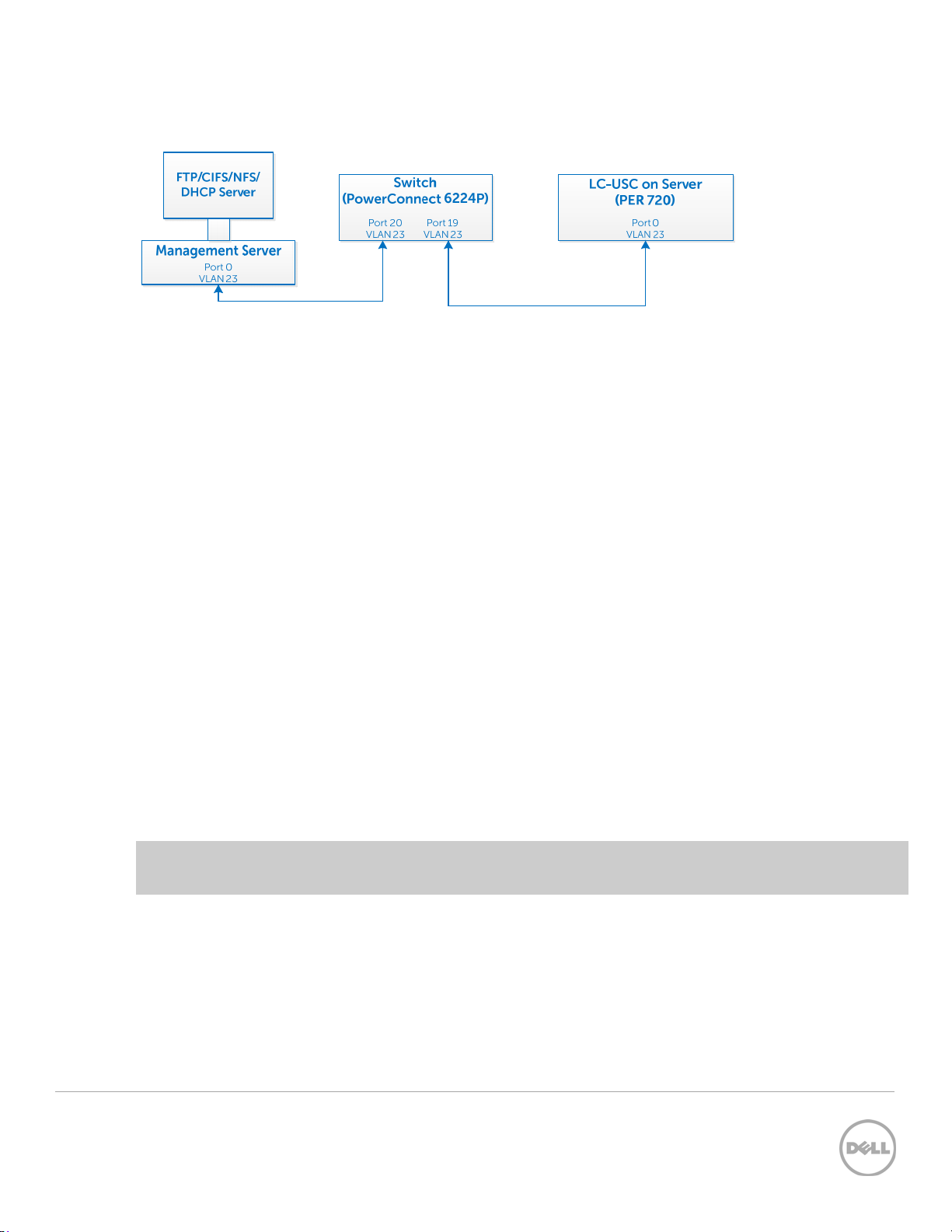
1 Network Setup for LC GUI with VLAN Settings
Figure 1 VLAN setup to use network features from LC GUI
As shown in the flow diagram here, you can select a Server Management domain for the Server
Management activities on the Dell PowerEdge servers. This can be achieved by using a VLAN, where the
management ports can be configured to operate with a particular VLAN ID. This provides an additional
security to the system management activities.
The Server Management software supported by the Dell PowerEdge servers such as iDRAC and Lifecycle
Controller can be accessed through the network, or a network is needed to perform various Server
Management activities. With a dedicated VLAN setup, you can configure all the Managed Server Network
ports to operate with a particular VLAN ID.
In the context of Lifecycle Controller, there are several network-dependent features that require DHCP
/NFS/CIFS/FTP servers for the network operations. All these servers can be configured to operate with a
specific VLAN ID dedicated for the Server Management. In Lifecycle Controller, system network port is
used for the network operations, which include Onboard LOMs and add-on cards.
A list of network features supported by LC GUI and the navigation path to each page are listed here:
1. To export the lifecycle log to a Network Share such as a CIFS or NFS, in the left pane click LifeCycle
Log, and then click Export LifeCycle Log,
2. To update the feature, and allow you to provide the FTP site, or the Network Share such as CIFS or
NFS at the source location, in the left pane click Firmware Update, and then click Launch Firmware
Update,
Note: To perform firmware updates of different components, store the firmware DUPs at appropriate
locations.
3. To allow you to export the Hardware Inventory files or Factory-Shipped Inventory file to a CIFS or NFS
share, in the left pane click Hardware Configuration, click Hardware Inventory, and then click Export
Hardware Inventory or Factory Shipped Inventory.
4. To allow the you to import server profile from either CIFS or NFS share, in the left pane click Platform
Restore, and then click Import Server Profile.
5 Configuring VLAN Settings in Lifecycle Controller for Dell PowerEdge Servers
Page 6

For more information about the earlier mentioned features, and additional features supported by the
Lifecycle Controller, refer to the
dell.com/support/manuals.
Lifecycle Controller1.3 User’s Guide
available at
1.1 Configuring VLAN Settings in LC GUI—Process Flow Chart
Figure 2 Process Flow Chart showing the tasks to configure VLAN Setting with IP Source as either DHCP
or Static
6 Configuring VLAN Settings in Lifecycle Controller for Dell PowerEdge Servers
Page 7
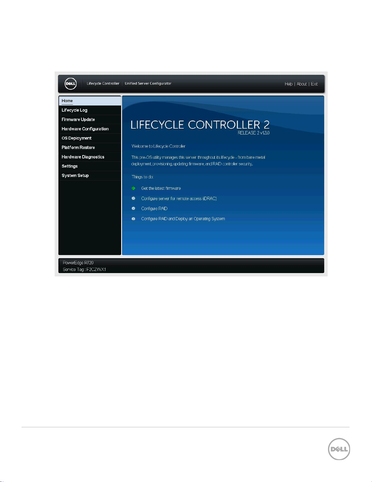
1.2 Configuring VLAN Settings in LC GUI
1. To start Lifecycle Controller, press <F10> during POST.
Figure 3 Lifecycle Controller Home page
7 Configuring VLAN Settings in Lifecycle Controller for Dell PowerEdge Servers
Page 8
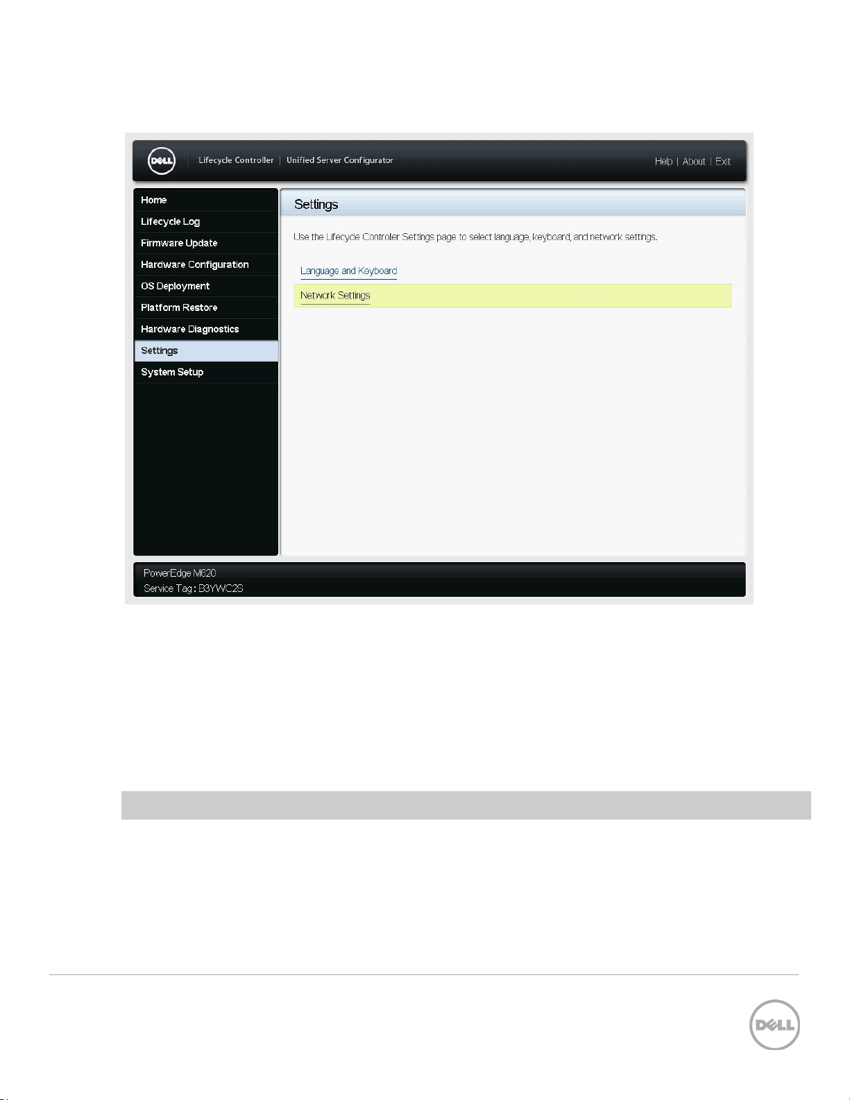
2. In the left pane, click Settings, and then click Network Settings.
Figure 4 LC GUI Settings Page
1.2.1 Setting DHCP Server as the IP Address Source
1. From the NIC Card drop-down menu, select a NIC card.
2. From the IP Address drop-down menu, select DHCP.
3. To type a priority level and VLAN ID within the specified value, under Lifecycle Controller VLAN
Settings, select Enable.
Note: Make sure network cable is connected to a NIC card which is selected for VLAN settings.
8 Configuring VLAN Settings in Lifecycle Controller for Dell PowerEdge Servers
Page 9

Figure 5 LC UI Network Settings Page
4. After typing appropriate information in the boxes, click Finish. Lifecycle Controller takes few
minutes to configure the network settings. A message is displayed to indicate that the network
settings are successfully updated. A sample screen shot is given here.
9 Configuring VLAN Settings in Lifecycle Controller for Dell PowerEdge Servers
Page 10

Figure 6 LC UI Network Settings success message
5. To check the IP address properties, in the left pane click Settings, and then click Network
Settings.
Note: 12G servers support only the IPv4 addresses.
10 Configuring VLAN Settings in Lifecycle Controller for Dell PowerEdge Servers
Page 11

Figure 7 LC GUI Network Settings Page
11 Configuring VLAN Settings in Lifecycle Controller for Dell PowerEdge Servers
Page 12

1.2.2 Setting Static IP as the IP Address Source
1. From the NIC Card drop-down menu, select a NIC Card.
2. From the IP Address drop-down menu, select Static, and then type data in the IP Address
Properties boxes.
3. To type the priority level and VLAN ID within the specified value, under Lifecycle Controller
VLAN Settings, select Enable.
Figure 8 VLAN Settings Enabled
Note: Make sure that the network cable is connected to the NIC card that is selected for the VLAN
settings.
A message is displayed to indicate that the network settings are successfully updated. A sample
screen shot is given here.
12 Configuring VLAN Settings in Lifecycle Controller for Dell PowerEdge Servers
Page 13

Figure 9 LC UI Network Settings success message
13 Configuring VLAN Settings in Lifecycle Controller for Dell PowerEdge Servers
Page 14

2 Error Scenarios and Resolution
1)
LNK0005: Unable to Connect to DHCP server
Description: If you make sure that the network cable is connected and the network configuration settings
are correct, then an error message will be displayed. A sample screen shot is given here.
Solution:
a. Try to verify if the network cable is connected and the network configuration settings are
correct. Else, retry the operation.
b. Update the Network Interface Controller (NIC) Card firmware to the latest version, and
then retry the operation.
Figure 10 LC GUI network settings critical error message
14 Configuring VLAN Settings in Lifecycle Controller for Dell PowerEdge Servers
Page 15

3 Warning Scenarios and Resolution
1)
Invalid VLAN ID
Description: A warning message is displayed to indicate if any letters, special character,s or a value typed
is not within 1–4094.
Solution:
a) Type a numeric value between 1-4094 for VLAN ID.
Figure 10 LC UI Network Settings invalid VLAN ID warning message
2)
Invalid Priority Number
Description: A warning message is displayed to indicate if any letters, special characters, or a value typed
is not between 0-7.
Solution:
a) Type a numeric value between 0–7 for priority number.
15 Configuring VLAN Settings in Lifecycle Controller for Dell PowerEdge Servers
Page 16

Figure 11 LC UI Network Settings invalid Priority Number warning message
16 Configuring VLAN Settings in Lifecycle Controller for Dell PowerEdge Servers
Page 17

4 Frequently Asked Questions
1. Can I use the FC Network Cards for Lifecycle Controller VLAN Settings?
Ans: You cannot use the FC Network Cards.
2. What are the VLAN Settings required to access the ftp.dell.com?
Ans: The default VLAN Settings (VLAN ID–1 and Priority–0).
3. Can I configure multiple ports and use in LC UI?
Ans: The LC GUI works with the latest configured port.
17 Configuring VLAN Settings in Lifecycle Controller for Dell PowerEdge Servers
Page 18

5 Best Practices
For recommended actions in case of any errors while configuring DHCP or STATIC Server, refer to the
“Error Scenarios and resolution”, “Warning Scenarios and resolution” sections in this white paper.
5.1 Technical White Paper
Table 1 Technical white paper definition
Is Is not
Is tested and validated on all the
12G servers, having LC2 1.3.0 and
iDARC 1.50.50 versions.
Is NOT supported on 11G or 12G
servers having LC2 1.2.0 version or
earlier.
18 Configuring VLAN Settings in Lifecycle Controller for Dell PowerEdge Servers
Page 19

A Supported Network Interface Cards For VLAN Settings
Using LC GUI
To configure VLAN Settings, on the Lifecycle Controller page, go to Settings Network Settings for all
the Dell supported network cards such as Broadcom, Intel, Qlogic, and Mellanox.
Note: All FC cards are not supported for VLAN Settings in LC UI such as Brocade, Emulex, and Qlogic.
To know the cards are either Ethernet or FC, refer to the
dell.com/support/manuals.
Sl.
No Description Vendor
1 57810S DP 10G SFP+ ADAPTER (Full Height) Broadcom
2 57810S DP 10G SFP+ ADAPTER (Low Profile) Broadcom
3 57800S DP 10G BASE-T ADAPTER (Full Height) Broadcom
4 57800S DP 10G BASE-T ADAPTER (Low Profile) Broadcom
5 5720 DP 1G ADAPTER (Full Height) Broadcom
6 5720 DP 1G ADAPTER (Low Profile) Broadcom
7 5719 QP 1G ADAPTER (Full Height) Broadcom
8 5719 QP 1G ADAPTER (Low Profile) Broadcom
Lifecycle Controller1.3 User’s Guide
available at
9 57800S QP rNDC (10G BASE-T + 1G BASE-T) Broadcom
10 57800S QP rNDC (10G SFP+ + 1G BASE-T) Broadcom
11 5720 QP rNDC 1G BASE-T Broadcom
12 57810S DP bNDC KR Broadcom
13 5719 QP 1G Mezz Broadcom
14 57810S DP 10G KR Mezz Broadcom
19 Configuring VLAN Settings in Lifecycle Controller for Dell PowerEdge Servers
Page 20

15 Broadcom 57840S Quad Port 10G SFP+ Rack NDC Broadcom
16 Broadcom 57840S-k Quad Port 10GbE Blade KR
Broadcom
NDC
17 i540 DP 10G BASE-T ADAPTER (Full Height) Intel
18 i540 DP 10G BASE-T ADAPTER (Low Profile) Intel
19 Intel DP 10GBASE SFP+ (Full Height) Intel
20 Intel DP 10GBASE SFP+ (Low Profile) Intel
21 i350 DP 1G ADAPTER (Full Height) Intel
22 i350 DP 1G ADAPTER (Low Profile) Intel
23 i350 QP 1G ADAPTER (Full Height) Intel
24 i350 QP 1G ADAPTER (Low Profile) Intel
25 i540 QP rNDC (10G BASE-T + 1G BASE-T) Intel
26 i350 QP rNDC 1G BASE-T Intel
27 i520 DP bNDC KR Intel
28 DP 10Gb KR Mezz Intel
29 DP 10Gb KR Mezz Intel
30 I350 QP 1G Mezz Intel
31 DP 10Gb SFP+/DA CNA (Full Height) Qlogic
32 DP 10Gb SFP+/DA CNA (Low Profile) Qlogic
33 10G DP bNDC KR Qlogic
34 Qlogic QME8262-k Mezz Qlogic
35 Qlogic CCRD NTWK 12G 10KR Qlogic
36 Mellanox ConnectX-3 Dual Port 10 GbE KR Blade
Mellanox
Mezzanine Card
20 Configuring VLAN Settings in Lifecycle Controller for Dell PowerEdge Servers
Page 21

37 Mellanox ConnectX-3 Dual Port 10 GbE DA/SFP+
Network Adapter (Full Height)
38 Mellanox ConnectX-3 Dual Port 10 GbE DA/SFP+
Network Adapter (Low Profile)
39 Mellanox ConnectX-3 Dual Port 40 GbE QSFP+
Network Adapter (Full Height)
40 Mellanox ConnectX-3 Dual Port 40 GbE QSFP+
Network Adapter (Low Profile)
Mellanox
Mellanox
Mellanox
Mellanox
21 Configuring VLAN Settings in Lifecycle Controller for Dell PowerEdge Servers
Page 22

B Unsupported Network Interface Cards For VLAN Settings
Using LC GUI
To configure VLAN settings from LC GUI (as these cards are not listed on the Network Settings page) and
to know the cards are either Ethernet or FC, refer to the
dell.com/support/manuals.
Sl. No Description Vendor
1 Cat II Dual Port SFP+ CNA (NPAR, FCoE, SR-IOV, ISoE) (Full Height) Brocade
2 Cat II Dual Port SFP+ CNA (NPAR, FCoE, SR-IOV, ISoE) (Low Profile) Brocade
3 Catapult II Dual Port 10Gb KR CNA Mezz(NPAR, FCOE, SR-IOV, ISoE) Brocade
4 Catapult I BR1741M Dual Port CNA Mezzanine Brocade
5 BR1020 10GB CNA Stand-up card (Full Height) Brocade
Lifecycle Controller1.3 User’s Guide
available at
6 BR1020 10GB CNA Stand-up card (Low Profile) Brocade
7 B-815 HBA 8Gbps Single Port (Full Height) Brocade
8 B-815 HBA 8Gbps Single Port (Low Profile) Brocade
9 B-825 HBA 8Gbps Dual Port (Full Height) Brocade
10 B-825 HBA 8Gbps Dual Port (Low Profile) Brocade
11 Qlogic FC8 Mezz Qlogic
12 QLE2662 Dual Port FC16 (Full Height) Qlogic
13 QLE2662 Dual Port FC16 (Low Profile) Qlogic
14 FC16 QLE2660 Single Port (Full Height) Qlogic
15 FC16 QLE2660 Single Port (Low Profile) Qlogic
16 FC16 QME2662 Mezz Qlogic
22 Configuring VLAN Settings in Lifecycle Controller for Dell PowerEdge Servers
Page 23

17 CRD,CTL,FC8,HB,QME2572,BLDE,V2 Qlogic
18 QLE2460 8Gbps Single Port (Full Height) Qlogic
19 QLE2462 8Gbps Dual Port (Full Height) Qlogic
20 QLE2560 8Gbps Single Port Qlogic
21 QLE2562 8Gbps Dual Port Qlogic
22 CRD,CTL,FC16,2P,LPE16002,EMLX (Full Height) Emulex
23 CRD,CTL,FC16,2P,LPE16002,LP,EMLX (Low Profile Emulex
24 CRD,CTL,FC16,1P,LPE16000,EMLX (Full Height) Emulex
25 CRD,CTL,FC16,1P,LPE16000,LP,EMLX (Low Profile) Emulex
26 CRD,CTL,FC8,HBA,SC,LPE12000,V2 (Full Height) Emulex
27 CRD,CTL,FC8,HBA,SC,LPE12000 (Low Profile) Emulex
28 CRD,CTL,FC8HBA,DLC,LPE12002,V2 (Full Height) Emulex
29 CRD,CTL,FC8HBA,DLC,LPE12002v(Low Profile) Emulex
30 LPE11002 FC4 HBA Emulex
31 LPe1150 FC4 HBA Emulex
32 LPe1205 FC8 HBA Emulex
33 LPe16000 Single Port FC16 HBA (Full Height) Emulex
34 LPe16000 Single Port FC16 HBA (Low Profile) Emulex
35 LPe16002 Dual Port FC16 HBA (Full Height) Emulex
36 LPe16002 Dual Port FC16 HBA (Low Profile) Emulex
37 FC16 Mezz Emulex
23 Configuring VLAN Settings in Lifecycle Controller for Dell PowerEdge Servers
Page 24

C Configuration Details
Table 2 Component table
Component Description
Firmware version LC2 1.3.0 and iDRAC 1.50.50
Application Lifecycle Controller
Server All Dell PowerEdge 12G servers
24 Configuring VLAN Settings in Lifecycle Controller for Dell PowerEdge Servers
Page 25

D Additional Resources
Support.dell.com is focused on meeting your needs with proven services and support.
DellTechCenter.com is an IT Community where you can connect with Dell Customers and Dell employees
for the purpose of sharing knowledge, best practices, and information about Dell products and
installations.
Referenced or recommended Dell publications:
Dell EqualLogic Configuration Guide:
http://en.community.dell.com/dell-groups/dtcmedia/m/mediagallery/19852516/download.aspx
Referenced or recommended Microsoft publications:
Microsoft SQL Server 2008: Disk Partition Alignment Best Practices for SQL Server:
http://msdn.microsoft.com/en-us/library/dd758814.aspx
Referenced or recommended Dell publications:
LifeCycle User Guide:
http://en.community.dell.com/dell-groups/dtcmedia/m/mediagallery/19852516/download.aspx
25 Configuring VLAN Settings in Lifecycle Controller for Dell PowerEdge Servers
 Loading...