

Dell latitude xpi cd Service Manual

Dell® Latitude® XPi CD
SERVICE MANUAL
®

Information in this manual is subject to change without notice.
1994–1996 Dell Computer Corporation. All rights reserved.
Reproduction in any manner whatsoever without the written permission of Dell Computer Corporation is strictly forbidden.
Trademarks used in this text: Dell, the DELL logo, and Latitude are registered trademarks of Dell Computer Corporation; Microsoft, Windows, and MS-DOS are
registered trademarks of Microsoft Corporation; Intel and Pentium are registered trademarks of Intel Corporation; IBM is a registered trademark of International
Business Machines Corporation.
Other trademarks and trade names may be used in this document to refer to either the entities claiming the marks and names or their products. Dell Computer
Corporation disclaims any proprietary interest in trademarks and trade names other than its own.
October 1996 P/N 30269

Contents
Chapter 1
System Overview. . . . . . . . . . . . . . . . . . . . . . . . . . . . . . . 1-1
System Features . . . . . . . . . . . . . . . . . . . . . . . . . . . . . . . . . . . . . . . . . . . . . . . 1-1
Physical Description . . . . . . . . . . . . . . . . . . . . . . . . . . . . . . . . . . . . . . . . . . . . 1-2
Indicator Panel . . . . . . . . . . . . . . . . . . . . . . . . . . . . . . . . . . . . . . . . . . . . . 1-3
Power/Suspend Indicator . . . . . . . . . . . . . . . . . . . . . . . . . . . . . . . . . . 1-4
Diskette-Drive Access Indicator. . . . . . . . . . . . . . . . . . . . . . . . . . . . . 1-4
Hard-Disk/CD-ROM Drive Access Indicator. . . . . . . . . . . . . . . . . . . 1-4
PC Card Access Indicator. . . . . . . . . . . . . . . . . . . . . . . . . . . . . . . . . . 1-4
Low-Battery Indicator. . . . . . . . . . . . . . . . . . . . . . . . . . . . . . . . . . . . . 1-4
Charging Indicator . . . . . . . . . . . . . . . . . . . . . . . . . . . . . . . . . . . . . . . 1-4
Keyboard Indicators . . . . . . . . . . . . . . . . . . . . . . . . . . . . . . . . . . . . . . 1-5
Controlling Computer Power . . . . . . . . . . . . . . . . . . . . . . . . . . . . . . . . . . . . . 1-5
Power States . . . . . . . . . . . . . . . . . . . . . . . . . . . . . . . . . . . . . . . . . . . . . . . 1-5
Interrupt Assignments. . . . . . . . . . . . . . . . . . . . . . . . . . . . . . . . . . . . . . . . . . . 1-6
Technical Specifications. . . . . . . . . . . . . . . . . . . . . . . . . . . . . . . . . . . . . . . . . 1-7
Chapter 2
Initial Procedures . . . . . . . . . . . . . . . . . . . . . . . . . . . . . . 2-1
Initial User Contact. . . . . . . . . . . . . . . . . . . . . . . . . . . . . . . . . . . . . . . . . . . . . 2-1
Visual Inspection . . . . . . . . . . . . . . . . . . . . . . . . . . . . . . . . . . . . . . . . . . . . . . 2-1
Observing the Boot Routine . . . . . . . . . . . . . . . . . . . . . . . . . . . . . . . . . . . . . . 2-4
Eliminating Resource Conflicts . . . . . . . . . . . . . . . . . . . . . . . . . . . . . . . . . . . 2-5
Getting Help . . . . . . . . . . . . . . . . . . . . . . . . . . . . . . . . . . . . . . . . . . . . . . . . . . 2-5
v

Chapter 3
Beep Codes and Error Messages. . . . . . . . . . . . . . . . . . 3-1
POST Beep Codes . . . . . . . . . . . . . . . . . . . . . . . . . . . . . . . . . . . . . . . . . . . . . 3-1
System Error Messages . . . . . . . . . . . . . . . . . . . . . . . . . . . . . . . . . . . . . . . . . 3-3
Running the Dell Diagnostics. . . . . . . . . . . . . . . . . . . . . . . . . . . . . . . . . . . . . 3-8
Chapter 4
Removing and Replacing Parts . . . . . . . . . . . . . . . . . . . 4-1
Recommended Tools . . . . . . . . . . . . . . . . . . . . . . . . . . . . . . . . . . . . . . . . . . . 4-2
Precautionary Measures . . . . . . . . . . . . . . . . . . . . . . . . . . . . . . . . . . . . . . . . . 4-2
Screw Identification and Tightening . . . . . . . . . . . . . . . . . . . . . . . . . . . . . . . 4-4
ZIF Connectors. . . . . . . . . . . . . . . . . . . . . . . . . . . . . . . . . . . . . . . . . . . . . . . . 4-5
Field-Replaceable Parts and Assemblies . . . . . . . . . . . . . . . . . . . . . . . . . . . . 4-6
Hard-Disk Drive Assembly . . . . . . . . . . . . . . . . . . . . . . . . . . . . . . . . . . . 4-7
Memory Compartment Cover . . . . . . . . . . . . . . . . . . . . . . . . . . . . . . . . . 4-8
Memory Modules . . . . . . . . . . . . . . . . . . . . . . . . . . . . . . . . . . . . . . . . . . . 4-9
Palmrest Assembly. . . . . . . . . . . . . . . . . . . . . . . . . . . . . . . . . . . . . . . . . . . . 4-10
Trackball Assembly . . . . . . . . . . . . . . . . . . . . . . . . . . . . . . . . . . . . . . . . 4-13
Keyboard Assembly. . . . . . . . . . . . . . . . . . . . . . . . . . . . . . . . . . . . . . . . 4-14
Display Assembly. . . . . . . . . . . . . . . . . . . . . . . . . . . . . . . . . . . . . . . . . . . . . 4-16
Tilt-Support Foot . . . . . . . . . . . . . . . . . . . . . . . . . . . . . . . . . . . . . . . . . . 4-16
Display Assembly. . . . . . . . . . . . . . . . . . . . . . . . . . . . . . . . . . . . . . . . . . 4-18
Display Assembly Bezel . . . . . . . . . . . . . . . . . . . . . . . . . . . . . . . . . . . . 4-20
Display Assembly Latch and Latch Spring . . . . . . . . . . . . . . . . . . . . . . 4-21
LCD Panel . . . . . . . . . . . . . . . . . . . . . . . . . . . . . . . . . . . . . . . . . . . . . . . 4-22
LCD Inverter Board . . . . . . . . . . . . . . . . . . . . . . . . . . . . . . . . . . . . . . . . 4-24
Hinge Covers . . . . . . . . . . . . . . . . . . . . . . . . . . . . . . . . . . . . . . . . . . . . . 4-25
Display-Assembly Interface Cable. . . . . . . . . . . . . . . . . . . . . . . . . . . . . 4-26
Microphone/Switch Assembly . . . . . . . . . . . . . . . . . . . . . . . . . . . . . . . . 4-28
Bottom Case Assembly . . . . . . . . . . . . . . . . . . . . . . . . . . . . . . . . . . . . . . . . 4-29
Diskette/CD-ROM Drive Assembly . . . . . . . . . . . . . . . . . . . . . . . . . . . 4-31
Deck Buoy . . . . . . . . . . . . . . . . . . . . . . . . . . . . . . . . . . . . . . . . . . . . . . . 4-33
Superpart Assembly . . . . . . . . . . . . . . . . . . . . . . . . . . . . . . . . . . . . . . . . 4-34
Reserve Battery . . . . . . . . . . . . . . . . . . . . . . . . . . . . . . . . . . . . . . . . . . . 4-36
System Board Assembly . . . . . . . . . . . . . . . . . . . . . . . . . . . . . . . . . . . . 4-38
Removing the System Board Assembly. . . . . . . . . . . . . . . . . . . . . . 4-39
Replacing the System Board Assembly . . . . . . . . . . . . . . . . . . . . . . 4-40
3.1-V Power Supply Board . . . . . . . . . . . . . . . . . . . . . . . . . . . . . . . . . . 4-41
vi

I/O-Panel Dust Cover . . . . . . . . . . . . . . . . . . . . . . . . . . . . . . . . . . . . . . . 4-42
Advanced Port Replicator Connector Dust Cover . . . . . . . . . . . . . . . . . 4-43
Audio Board . . . . . . . . . . . . . . . . . . . . . . . . . . . . . . . . . . . . . . . . . . . . . . 4-44
Appendix A
Factory Repair Parts . . . . . . . . . . . . . . . . . . . . . . . . . . . . A-1
Recommended Tools . . . . . . . . . . . . . . . . . . . . . . . . . . . . . . . . . . . . . . . . . . .A-1
Precautionary Measures . . . . . . . . . . . . . . . . . . . . . . . . . . . . . . . . . . . . . . . . .A-1
Factory Repair Parts and Assemblies . . . . . . . . . . . . . . . . . . . . . . . . . . . . . . .A-1
Exploded Views of Components and Assemblies . . . . . . . . . . . . . . . . . . . .A-12
Hard-Disk Drive . . . . . . . . . . . . . . . . . . . . . . . . . . . . . . . . . . . . . . . . . . .A-15
CD-ROM Drive . . . . . . . . . . . . . . . . . . . . . . . . . . . . . . . . . . . . . . . . . . .A-16
Diskette Drive. . . . . . . . . . . . . . . . . . . . . . . . . . . . . . . . . . . . . . . . . . . . .A-16
Palmrest Assembly Components . . . . . . . . . . . . . . . . . . . . . . . . . . . . . . . . .A-16
Trackball. . . . . . . . . . . . . . . . . . . . . . . . . . . . . . . . . . . . . . . . . . . . . . . . .A-16
Trackball Interface Cable . . . . . . . . . . . . . . . . . . . . . . . . . . . . . . . . . . . .A-16
Trackball Button Board . . . . . . . . . . . . . . . . . . . . . . . . . . . . . . . . . . . . .A-16
Palmrest Brace . . . . . . . . . . . . . . . . . . . . . . . . . . . . . . . . . . . . . . . . . . . .A-16
Display Assembly Components . . . . . . . . . . . . . . . . . . . . . . . . . . . . . . . . . .A-17
Display-Assembly EMI Shield . . . . . . . . . . . . . . . . . . . . . . . . . . . . . . . .A-17
Display Assembly Base . . . . . . . . . . . . . . . . . . . . . . . . . . . . . . . . . . . . .A-18
Display Assembly Hinges. . . . . . . . . . . . . . . . . . . . . . . . . . . . . . . . . . . .A-19
System-Board Assembly Components . . . . . . . . . . . . . . . . . . . . . . . . . . . . .A-20
System Board . . . . . . . . . . . . . . . . . . . . . . . . . . . . . . . . . . . . . . . . . . . . .A-20
Keyboard/Keypad/Mouse Connector Shield . . . . . . . . . . . . . . . . . . . . .A-21
I/O Interface Cable . . . . . . . . . . . . . . . . . . . . . . . . . . . . . . . . . . . . . . . . .A-22
I/O Board . . . . . . . . . . . . . . . . . . . . . . . . . . . . . . . . . . . . . . . . . . . . . . . .A-23
I/O Panel . . . . . . . . . . . . . . . . . . . . . . . . . . . . . . . . . . . . . . . . . . . . . . . . .A-24
Bottom-Case Assembly Components . . . . . . . . . . . . . . . . . . . . . . . . . . . . . .A-25
Main Battery Insulator . . . . . . . . . . . . . . . . . . . . . . . . . . . . . . . . . . . . . .A-25
Power Button and Power-Button Mounting Bracket . . . . . . . . . . . . . . .A-26
Spreader and Keel Plates . . . . . . . . . . . . . . . . . . . . . . . . . . . . . . . . . . . .A-27
Appendix B
System Setup Options . . . . . . . . . . . . . . . . . . . . . . . . . . B-1
Accessing the Dell Control Center . . . . . . . . . . . . . . . . . . . . . . . . . . . . . . . . .B-1
Accessing the System Setup Program . . . . . . . . . . . . . . . . . . . . . . . . . . . . . .B-2
System Setup Screens. . . . . . . . . . . . . . . . . . . . . . . . . . . . . . . . . . . . . .B-3
vii

Index
Figures
Figure 1-1. Front View of the Notebook Computer. . . . . . . . . . . . . . . . . . 1-2
Figure 1-2. Back View of the Notebook Computer . . . . . . . . . . . . . . . . . . 1-3
Figure 1-3. Indicator Panel. . . . . . . . . . . . . . . . . . . . . . . . . . . . . . . . . . . . . 1-3
Figure 4-1. Computer Orientation . . . . . . . . . . . . . . . . . . . . . . . . . . . . . . . 4-1
Figure 4-2. Main Battery Assembly Removal . . . . . . . . . . . . . . . . . . . . . . 4-3
Figure 4-3. Screw Identification. . . . . . . . . . . . . . . . . . . . . . . . . . . . . . . . . 4-4
Figure 4-4. Disconnecting an Interface Cable . . . . . . . . . . . . . . . . . . . . . . 4-5
Figure 4-5. Exploded View—Computer . . . . . . . . . . . . . . . . . . . . . . . . . . 4-6
Figure 4-6. Hard-Disk Drive Assembly Removal . . . . . . . . . . . . . . . . . . . 4-7
Figure 4-7. Memory Compartment Cover Removal . . . . . . . . . . . . . . . . . 4-8
Figure 4-8. Memory Module Removal . . . . . . . . . . . . . . . . . . . . . . . . . . . 4-9
Figure 4-9. Palmrest Assembly Removal. . . . . . . . . . . . . . . . . . . . . . . . . 4-10
Figure 4-10. Palmrest-Assembly Retaining Screws. . . . . . . . . . . . . . . . . . 4-11
Figure 4-11. Trackball Assembly Removal . . . . . . . . . . . . . . . . . . . . . . . . 4-13
Figure 4-12. Keyboard Assembly Removal. . . . . . . . . . . . . . . . . . . . . . . . 4-14
Figure 4-13. Tilt-Support Foot Removal . . . . . . . . . . . . . . . . . . . . . . . . . . 4-16
Figure 4-14. Display Assembly Removal . . . . . . . . . . . . . . . . . . . . . . . . . 4-18
Figure 4-15. Display Assembly Bezel Removal . . . . . . . . . . . . . . . . . . . . 4-20
Figure 4-16. Display Assembly Latch and Latch Spring Removal . . . . . . 4-21
Figure 4-17. LCD Panel Removal . . . . . . . . . . . . . . . . . . . . . . . . . . . . . . . 4-22
Figure 4-18. LCD Inverter Board Removal . . . . . . . . . . . . . . . . . . . . . . . . 4-24
Figure 4-19. Hinge Covers Removal . . . . . . . . . . . . . . . . . . . . . . . . . . . . . 4-25
Figure 4-20. Display-Assembly Interface Cable Removal . . . . . . . . . . . . 4-26
Figure 4-21. Microphone/Switch Assembly Removal. . . . . . . . . . . . . . . . 4-28
Figure 4-22. Bottom Case Assembly Removal . . . . . . . . . . . . . . . . . . . . . 4-30
Figure 4-23. Diskette/CD-ROM Drive Assembly Removal . . . . . . . . . . . 4-31
Figure 4-24. Deck Buoy Removal . . . . . . . . . . . . . . . . . . . . . . . . . . . . . . . 4-33
Figure 4-25. Superpart Assembly Removal . . . . . . . . . . . . . . . . . . . . . . . . 4-34
Figure 4-26. Reserve Battery Removal . . . . . . . . . . . . . . . . . . . . . . . . . . . 4-36
Figure 4-27. System Board Assembly Removal . . . . . . . . . . . . . . . . . . . . 4-38
Figure 4-28. I/O Bracket Clips. . . . . . . . . . . . . . . . . . . . . . . . . . . . . . . . . . 4-40
Figure 4-29. 3.1-V Power Supply Board Removal . . . . . . . . . . . . . . . . . . 4-41
viii
Figure 4-30. I/O-Panel Dust Cover Removal. . . . . . . . . . . . . . . . . . . . . . . 4-42
Figure 4-31. Advanced Port Replicator Connector Dust Cover. . . . . . . . . 4-43
Figure 4-32. Audio Board Removal. . . . . . . . . . . . . . . . . . . . . . . . . . . . . . 4-44

Figure A-1. Exploded View—Display Assembly . . . . . . . . . . . . . . . . . . .A-12
Figure A-2. Exploded View—Palmrest Assembly . . . . . . . . . . . . . . . . . .A-13
Figure A-3. Exploded View—Bottom Case Assembly. . . . . . . . . . . . . . .A-14
Figure A-4. Display-Assembly EMI Shield Removal. . . . . . . . . . . . . . . .A-17
Figure A-5. System Board Assembly in the Bottom Case Assembly . . . .A-20
Figure A-6. Keyboard/Keypad/Mouse Connector Shield Removal . . . . .A-21
Figure A-7. I/O Interface Cable Removal . . . . . . . . . . . . . . . . . . . . . . . . .A-22
Figure A-8. I/O Board Removal . . . . . . . . . . . . . . . . . . . . . . . . . . . . . . . .A-23
Figure A-9. I/O Panel Removal. . . . . . . . . . . . . . . . . . . . . . . . . . . . . . . . .A-24
Figure A-10. Bottom-Case Assembly Components . . . . . . . . . . . . . . . . . .A-25
Figure A-11. Power Button and Power-Button Mounting Bracket
Removal . . . . . . . . . . . . . . . . . . . . . . . . . . . . . . . . . . . . . . . . .A-26
Figure A-12. Spreader and Keel Plate Removal . . . . . . . . . . . . . . . . . . . . .A-27
Figure B-1. Dell Control Center Icon . . . . . . . . . . . . . . . . . . . . . . . . . . . . .B-1
Figure B-2. Dell Control Center Window . . . . . . . . . . . . . . . . . . . . . . . . . .B-1
Figure B-3. System Setup Screens . . . . . . . . . . . . . . . . . . . . . . . . . . . . . . .B-3
Tables
Table 1-1. Interrupt Assignments . . . . . . . . . . . . . . . . . . . . . . . . . . . . . . . 1-6
Table 1-2. Technical Specifications . . . . . . . . . . . . . . . . . . . . . . . . . . . . . 1-7
Table 3-1. POST Beep Codes . . . . . . . . . . . . . . . . . . . . . . . . . . . . . . . . . . 3-1
Table 3-2. System Error Messages . . . . . . . . . . . . . . . . . . . . . . . . . . . . . . 3-3
Table A-1. Factory Repair Parts and Assemblies. . . . . . . . . . . . . . . . . . . .A-2
Table B-1. System Setup Program Categories. . . . . . . . . . . . . . . . . . . . . .B-4
ix

R
ead This First
A prerequisite for using this manual to service Dell portable computers is a
basic knowledge of IBM®-compatible PCs and prior training in IBMcompatible PC troubleshooting techniques. In addition to information
provided in this manual, Dell provides the Reference and Troubleshooting
Guide for troubleshooting procedures and instructions on using the Dell
diagnostics to test portable computers, and the online System User ’s Guide
for information about system setup and operations.
W
arnings, Cautions, and Notes
Throughout this manual, there may be blocks of text printed in bold type or in
italic type. These blocks are warnings, cautions, and notes, and they are used as
follows:
WARNING: A WARNING indicates the potential for bodily harm and
provides instructions for how to avoid the problem.
CAUTION: A CAUTION indicates either potential damage to hardware
or loss of data and provides instructions for how to avoid the problem.
NOTE: A NOTE provides helpful information about using the computer system.
x

Chapter 1
System Overview
T
he Dell® Latitude® XPi CD is a lightweight, expandable portable computer
that use the Intel® Pentium® microprocessor. This chapter provides an ov erview
of the features and technical specifications of this computer.
S
ystem Features
In addition to the standard features found in a Dell portable computer, the Dell
Latitude XPi CD models include the following new features:
• 64-bit-wide data bus.
• 60-MHz local bus and a 30-MHz PCI bus.
• 256-KB pipelined-burst SRAM secondary cache.
• 16 MB of nonremovable, EDO-type memory built in to the system board.
Memory can be increased up to 48 MB by installing combinations of 8- and
16-MB fast-page memory modules in the two memory sockets on the system board.
• 128-bit accelerated graphics adapter with 1.1 MB of integrated video mem-
ory. The integrated video adapter is attached to the PCI bus.
• Full multimedia capability through the following standard features:
— A built-in CD-ROM drive
— MPEG software
— Hardware wavetable support
— SoundBlasterPro-compati ble voice and music functions
— Jacks for connecting external speakers, headphones, or a microphone
• Two infrared ports that compatible with the Infrared Data Association
(IrDA) Standard 1.1 (Fast IR) for use with external devices.
• Keyboard with sound and Microsoft
®
Windows® operating system support.
• Support for two 3.3-V or 5-V PC Cards that adhere to the standards of the
Personal Computer Memory Card International Association (PCMCIA).
The computer supports type I, type II, or type III cards (in any
combination).
For a complete list of system features, see “Technical Specifications” found
later in this chapter.
System Overview 1-1
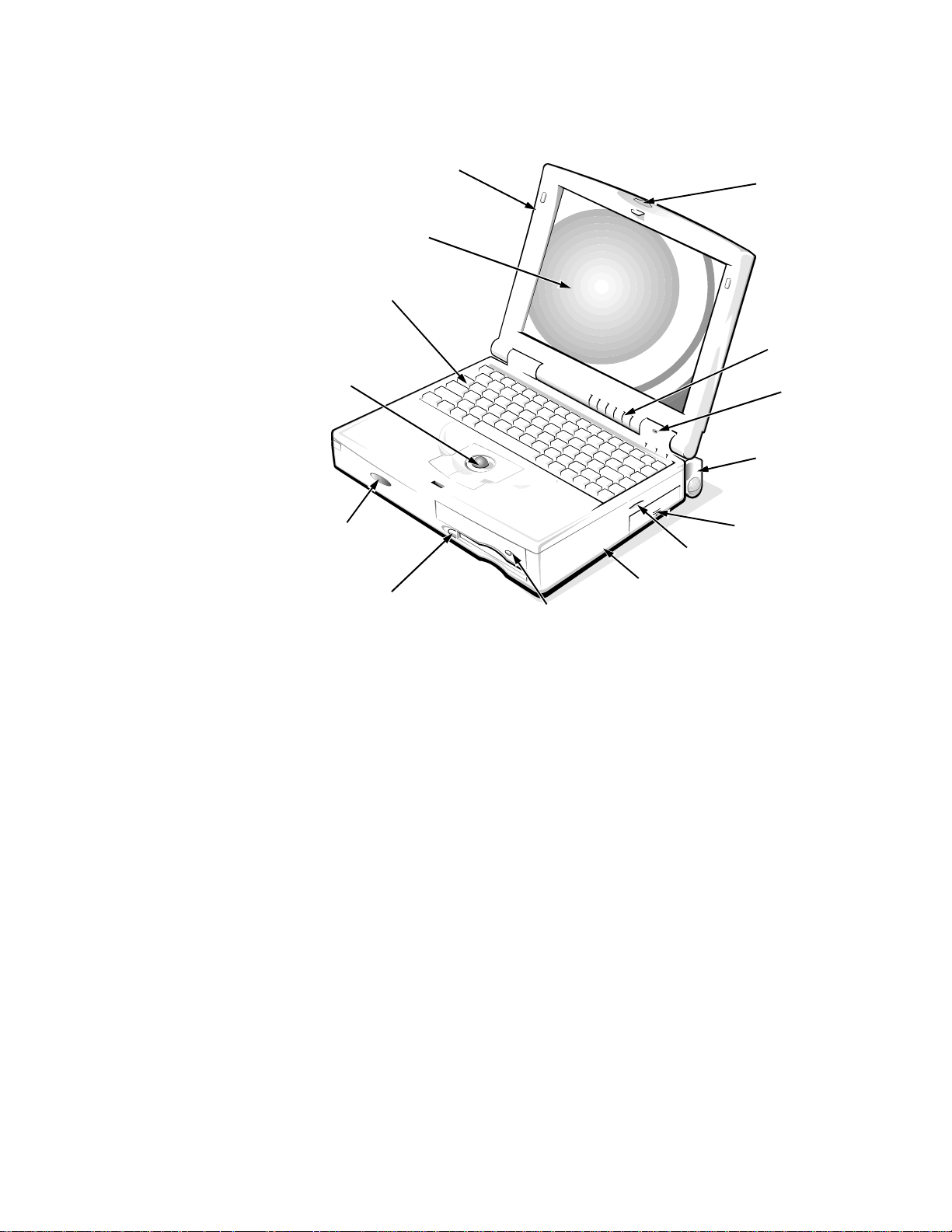
P
hysical Description
display assembly
LCD panel
keyboard
trackball
assembly
display assembly
latch
indicator panel
microphone
tilt-support foot (2)
infrared port
speaker
diskette drive
CD-ROM drive
bottom case assembly
Figure 1-1. Front View of the Notebook Computer
main battery assembly
1-2 Dell Latitude XPi CD Service Manual
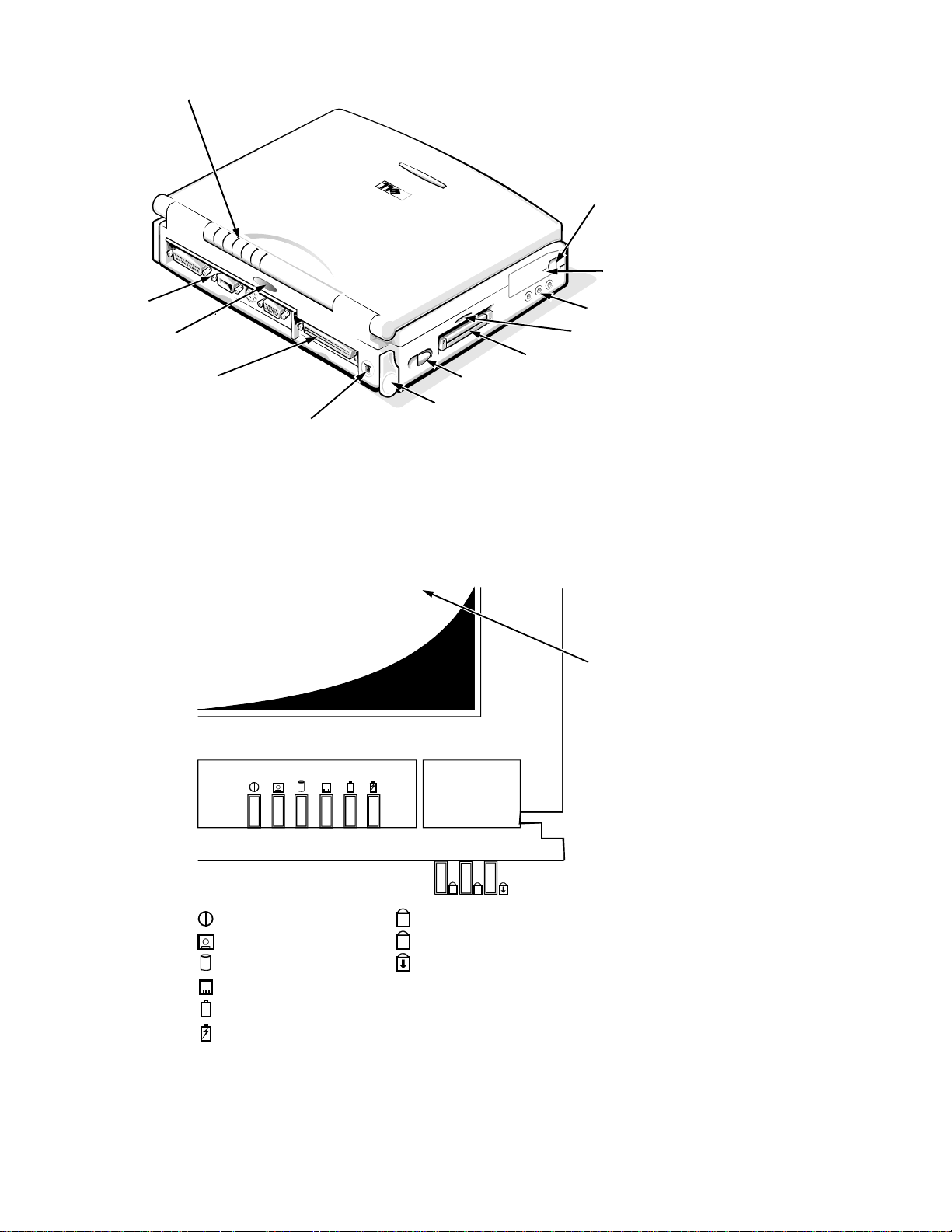
indicator panel
I/O panel
infrared port
Advanced Port
Replicator connector
DC power input connector
power switch
tilt-support foot
Figure 1-2. Back View of the Notebook Computer
hard-disk drive
security
cable slot
audio jacks (3)
speaker
PC Card slot
Indicator Panel
Legend
power/suspend indicator
diskette-drive access indicator
hard-disk/CD-ROM drive
access indicator
PC Card access indicator
low-battery indicator
charging indicator
LCD panel
Num Lock indicator
Caps Lock indicator
Scroll Lock indicator
Figure 1-3. Indicator Panel
System Overview 1-3

The portable computer has nine indicators: six on the display assembly’s indi cator panel and three on the keyboard assembly. Each of the six indicators on the
display assembly has an identical pair of LEDs: one is visible on the indicator
panel when the display is open, and the other is visible through an aperture on
the outside of the display assembly when the display is fully closed. The subsections that follow describe the functions of the indicators.
Power/Suspend Indicator
The power/suspend indicator is a green LED. After the computer is turned on,
the power/suspend indicator lights up constantly to indicate that the computer is
receiving stable power. When the computer enters suspend mode, the indicator
blinks once approximately every 8 seconds.
Diskette-Drive Access Indicator
The diskette-drive access indicator is a green LED. The indicator lights when
data is being transferred to or from the diskette drive.
Hard-Disk/CD-ROM Drive Access Indicator
The hard-disk/CD-ROM drive access indicator is a green LED. The indicator
lights when data is being transferred to or from the hard-disk drive or the
CD-ROM.
PC Card Access Indicator
The PC Card access indicator is a green LED. The indicator lights when data is
being transferred to or from an installed PC Card (also known as a PCMCIA
card).
Low-Battery Indicator
The low-battery indicator is an amber LED. This indicator is used in conjunction with the speaker to indicate either of the following low-battery conditions:
• The first low-battery warning occurs when the main battery’s charge has
been depleted to 8 percent of its fully charged condition. The low-battery
indicator turns on and the speaker emits five beeps.
• The second and final low-battery warning occurs when the main battery’s
charge has been depleted to 3 percent of its fully charged condition. The
speaker beeps twice every 1 to 2 seconds for 15 seconds; then the system
does a suspend-to-disk operation automatically before shutting down.
Charging Indicator
The charging indicator is an amber LED. The indicator turns on when the main
battery begins charging and blinks to show the battery is fully charged.
1-4 Dell Latitude XPi CD Service Manual

Keyboard Indicators
The keyboard controls the operation of the numeric lock (Num Lock) indicator,
the capitals lock (Caps Lock) indicator, and the Scroll Lock indicator, all of
which are visible through apertures at the top of the keyboard. These indicators
are associated with the <NUM LOCK> key, the <CAPS LOCK> key, and the
<SCROLL LOCK> key; when lit, the LEDs indicate the active state of these
keys.
C
ontrolling Computer Power
The power button does not directly control power to the computer. Instead,
when you slide the power button toward the front of the computer and then
release it, the button momentarily closes the power switch on the system board.
The power switch sends a signal to the power management controller, signaling
the controller to initiate a change of state of the computer’s power. The resulting
power state depends on the present power state. The following subsection gives
a description of the power states.
Power States
Sliding the power button toward the front of the computer initiates a change
from the current power state to a different state. The protocols for the power
state changes are as follows:
• If the computer is off (no indicators on) and the display is open and/or an
external monitor is attached to the computer, sliding the power button initiates a boot operation.
• If the computer is off, if the display is closed, and if no external monitor is
attached, sliding the power button causes the computer to run the POST and
then turn off.
• If the computer is on and the SYSTEM SWITCH option in S ystem S etu p is set
to ON/OFF, sliding the power button turns off the computer.
• If the computer is on and the SYSTEM SWITCH option in System Setup is set
to S2D/RFD, sliding the power button causes the compute r to enter sus p endto-disk mode.
• If the computer is in suspend mode (the power/suspend indicator flashes
every 8 seconds), if the SYSTEM SWITCH option in System Setup is set to
ON/OFF, and if the display is open or an external monitor is attached, sliding
the power button turns off the computer.
• If the computer is in suspend mode (the power/suspend indicator flashes
every 8 seconds), if the SYSTEM SWITCH option in System Setup is set to
S2D/RFD, and if the display is open or an external monitor is attached, sliding
the power button caus es the co mp uter t o ent er s uspen d- to -d is k m ode .
System Overview 1-5

• If the computer is in suspend mode (the power/suspend indicator flashes
every 8 seconds), if the display is closed, and if no external monitor is
attached, sliding the power button has no effect on the power state. The
computer remains in suspend mode.
• If the computer is in suspend-to-disk mode, sliding the power button causes
the computer to initiate the resume-from-disk operation.
I
nterrupt Assignments
Table 1-1. Interrupt Assignments
IRQ Line Used/Available
IRQ0 Generated by the system timer
IRQ1 Generated by the keyboard controller to signal that the keyboard
output buffer is full
IRQ2 Generated internally by the interrupt controller to enable IRQ8
through IRQ15
IRQ3 Available for use by a PC Card unless the built-in serial port or
infrared port is configured for COM2 (the default)
IRQ4 Available for use by a PC Card unless the built-in serial port is
configured for COM1 (the default)
IRQ5 Available for use by the audio controller
IRQ6 Generated by the diskette drive controller to indicate that the
diskette drive requires the attention of the microprocessor
IRQ7 Available for use by a PC Card or audio controller if the built-in
parallel port is disabled
IRQ8 Generated by the system I/O controller’s RTC
IRQ9 Available for use by the PC Card interrupt controller or the
audio controller
IRQ10 Available for use by a PC Card or audio controller unless the
Advanced Port Replicator is attached
IRQ11 Available for use by a PC Card unless the Advanced Port Repli-
cator is attached
IRQ12 Generated by the keyboard controller to indicate that the output
buffer of the integrated trackball or external PS/2 mouse is full
IRQ13 Reserved for use by the internal coprocessor
IRQ14 Generated by the hard-disk drive to indicate that the drive
IRQ15 Reserved for the CD-ROM drive
1-6 Dell Latitude XPi CD Service Manual
requires the attention of the microprocessor

T
echnical Specifications
Table 1-2. Technical Specifications
Microprocessor
Microprocessor type . . . . . . . . . . . Intel Pentium microprocessor
Microprocessor speed . . . . . . . . . . 150 MHz
Bus architecture . . . . . . . . . . . . . . PCI
Internal cache memory . . . . . . . . . 16 KB
External cache memory. . . . . . . . . 256 KB pipelined-burst SRAM
Math coprocessor . . . . . . . . . . . . . internal to the microprocessor
Chip Set and Bus
System chip set . . . . . . . . . . . . . . . Pico Power Vesuvius-LS Core Logic
Microprocessor data bus width. . . 64 bits
DRAM bus width . . . . . . . . . . . . . 64 bits
Address bus width. . . . . . . . . . . . . 32 bits
Security EEPROM . . . . . . . . . . . . 256 bytes
Flash EPROM. . . . . . . . . . . . . . . . 256 KB
Local bus. . . . . . . . . . . . . . . . . . . . 60 MHz
PCI bus . . . . . . . . . . . . . . . . . . . . . 30 MHz
PC Card
PC Card controller . . . . . . . . . . . . Texas Instruments PCI1130 CardBus
controller
PC Card connectors . . . . . . . . . . . two (supports type I and type II cards in
any combination; type III cards can be
used only with type I or type II cards)
Cards supported . . . . . . . . . . . . . . 3.3-V and 5-V
PC Card connector size. . . . . . . . . 68 pins
Data width (maximum). . . . . . . . . 32 bits
Memory
Architecture . . . . . . . . . . . . . . . . .
Memory module sockets. . . . . . . . two
1
The system supports fast-page-mode memory modules for memory upgrades.
EDO memory1
System Overview 1-7

Table 1-2. Technical Specificati ons
(Continued)
Memory
(Continued)
Memory module type and
capacities . . . . . . . . . . . . . . . . . . . 8- and 16-MB fast-page mode
Standard RAM . . . . . . . . . . . . . . . 16 MB (EDO) on system board
Maximum RAM. . . . . . . . . . . . . . 48 MB
Memory access time:
tRAC . . . . . . . . . . . . . . . . . . . 70 ns
tCAC . . . . . . . . . . . . . . . . . . . 20 ns
BIOS address . . . . . . . . . . . . . . . . F000:0000
Connectors
Serial (DTE) . . . . . . . . . . . . . . . . . one 9-pin connector; 16550-compatible,
16-byte buffer
Parallel . . . . . . . . . . . . . . . . . . . . . one 25-hole connector; unidirectional,
bidirectional, EPP 1.9, or ECP
Monitor. . . . . . . . . . . . . . . . . . . . . one 15-hole connector
PS/2 . . . . . . . . . . . . . . . . . . . . . . . one 6-pin mini-DIN (this connector does
not support more than one device at a time)
Infrared. . . . . . . . . . . . . . . . . . . . . two ports compatible with IrDA
Standard 1.1 (Fast IR)
Audio . . . . . . . . . . . . . . . . . . . . . . microphone-in
line-in/audio-in
headphones/speakers
Advanced Port Replicator . . . . . . 200-pin connector
Audio
Audio type . . . . . . . . . . . . . . . . . . SoundBlasterPro-compatible 3.01
voice and music functions
Audio controller . . . . . . . . . . . . . . ES1888
ES690 wavetable music synthesizer,
ES938 3D audio spatializer
Stereo conversion . . . . . . . . . . . . . 16 bit (analog-to-digital and digital-
to-analog)
FM music synthesizer. . . . . . . . . . 20-voice, 72-operator
1-8 Dell Latitude XPi CD Service Manual

Table 1-2. Technical Specifications
(Continued)
Audio
(Continued)
Interfaces:
Internal . . . . . . . . . . . . . . . . . . ISA bus
External. . . . . . . . . . . . . . . . . . stereo line-in minijack
microphone-in minijack
headphones/speakers-out minijack
Speakers . . . . . . . . . . . . . . . . . . . . four 8-ohm speakers
Internal speaker amplifier . . . . . . . 1 W into 8 ohms stereo
Headphones amplifier. . . . . . . . . . 150 mW into 32 ohms stereo
Controls. . . . . . . . . . . . . . . . . . . . . volume can be controlled through key
combinations, software application
menus, or the Speaker window in the Dell
Control Center
Video
Video type. . . . . . . . . . . . . . . . . . . hardware-accelerated, 128-bit PCI
Video controller . . . . . . . . . . . . . . NeoMagic 2090
Integrated video memory . . . . . . . 1.1 MB
Display
Type. . . . . . . . . . . . . . . . . . . . . . . . active-matrix color (TFT)
Dimensions:
Height . . . . . . . . . . . . . . . . . . . 195.0 mm (7.68 inches)
Width. . . . . . . . . . . . . . . . . . . . 272.0 mm (10.7 inches)
Diagonal . . . . . . . . . . . . . . . . . 307.5 mm (12.1 inches)
Maximum resolution. . . . . . . . . . . 800 x 600 pixels; 65,536 colors
Response time (typical) . . . . . . . . 80 ms
Operating angle. . . . . . . . . . . . . . . 0° (closed) to 180°
Dot pitch . . . . . . . . . . . . . . . . . . . . 0.31 mm
Power consumption:
Panel (typical). . . . . . . . . . . . . 0.69 W
Backlight. . . . . . . . . . . . . . . . . 2.10 W
Controls. . . . . . . . . . . . . . . . . . . . . brightness can be controlled through a key
combination, the Display window in the
Dell Control Center, or the System Setup
program
System Overview 1-9

Table 1-2. Technical Specificati ons
Keyboard
(Continued)
Number of keys . . . . . . . . . . . . . . 85 (U.S., Canada, Korea, Thailand, and
locations that use traditional Chinese);
86 (Europe);
87 (Japan)
Key travel . . . . . . . . . . . . . . . . . . . 3.0 ± 0.5 mm (0.12 ± 0.02 inch)
Key spacing . . . . . . . . . . . . . . . . . 18.25 mm (0.72 inch)
Layout. . . . . . . . . . . . . . . . . . . . . . QWERTY, AZERTY, Kanji
Battery
Type . . . . . . . . . . . . . . . . . . . . . . . lithium ion
Dimensions:
Height. . . . . . . . . . . . . . . . . . . 20.5 mm (0.81 inch)
Depth . . . . . . . . . . . . . . . . . . . 152.75 mm (6.01 inches)
Width . . . . . . . . . . . . . . . . . . . 78.5 mm (3.09 inches)
Weight. . . . . . . . . . . . . . . . . . . . . . 0.41 kg (0.9 lb)
Voltage . . . . . . . . . . . . . . . . . . . . . 14.4 VDC
Capacity . . . . . . . . . . . . . . . . . . . . 36 WH
Charge time (approximate):
2
Computer on. . . . . . . . . . . . . . 2.5 hours
Computer off . . . . . . . . . . . . . 1.5 hours
Operating time (approximate, with no
power management features
enabled)2. . . . . . . . . . . . . . . . . . . .
2 to 3.5 hours (without a CD-ROM drive
in use)
Life span (approximate)2 . . . . . . .
400 discharge/charge cycles
Temperature range:
Charge . . . . . . . . . . . . . . . . . . 10° to 40°C (50° to 104°F)
Discharge . . . . . . . . . . . . . . . . 10° to 40°C (50° to 104°F)
Storage . . . . . . . . . . . . . . . . . . –40° to 65°C (–40° to 149°F)
2
Battery performance features such as charge time, operating time, and life span can vary according
to the conditions under which the computer and battery are used.
1-10 Dell Latitude XPi CD Service Manual

Table 1-2. Technical Specifications
(Continued)
Battery
(Continued)
NiCad reserve battery:
Voltage . . . . . . . . . . . . . . . . . . 7.2 V
Operating time
(approximate) . . . . . . . . . . . . . 2 minutes (if computer is in battery swap
mode); 40 days (if power is
turned off)
AC Adapter
Input voltage . . . . . . . . . . . . . . . . . 90 to 135 VAC and 164 to 264 VAC
Input current (maximum) . . . . . . . 1.2 A and 0.6 A
Input frequency. . . . . . . . . . . . . . . 47 to 63 Hz
Output current. . . . . . . . . . . . . . . . 4.5 A (maximum);
3.5 A (continuous)
Rated output voltage. . . . . . . . . . . 18.5 VDC
Height . . . . . . . . . . . . . . . . . . . . . . 27.94 mm (1.1 inches)
Width. . . . . . . . . . . . . . . . . . . . . . . 58.42 mm (2.3 inches)
Depth. . . . . . . . . . . . . . . . . . . . . . . 133.35 mm (5.25 inches)
Weight (with cables) . . . . . . . . . . 0.4 kg (0.89 lb)
Temperature range:
Operating . . . . . . . . . . . . . . . . 0° to 40°C (32° to 104°F)
Storage . . . . . . . . . . . . . . . . . . -40° to 70°C (-40° to 158°F)
CD-ROM Drive3
Disc size . . . . . . . . . . . . . . . . . . . . 8 cm and 12 cm (no adapter required)
Data transfer rate:
Sustained. . . . . . . . . . . . . . . . . 900 KB/sec (mode 2 disc)
Burst . . . . . . . . . . . . . . . . . . . . 14.4 MB/sec (PIO mode 3)
Seek time:
Random. . . . . . . . . . . . . . . . . . 200 m/sec
Full-stroke. . . . . . . . . . . . . . . . 500 m/sec
3
The CD-ROM drive in your computer may have different specifications.
System Overview 1-11

Table 1-2. Technical Specificati ons
(Continued)
CD-ROM Drive
3
(Continued)
Access time:
Random . . . . . . . . . . . . . . . . . 250 m/sec
Full-stroke . . . . . . . . . . . . . . . 550 m/sec
Memory buffer . . . . . . . . . . . . . . . 128 KB
Physical (Computer)
Height. . . . . . . . . . . . . . . . . . . . . . 63.0 mm (2.48 inches)
Width . . . . . . . . . . . . . . . . . . . . . . 280.9 mm (11.06 inches)
Depth . . . . . . . . . . . . . . . . . . . . . . 233.5 mm (9.19 inches)
Weight (with battery and
hard-disk drive) . . . . . . . . . . . . . . 3.29 kg (7.26 lb)
Environmental
Temperature:
Operating . . . . . . . . . . . . . . . . 10° to 40°C (50° to 104°F)
Storage . . . . . . . . . . . . . . . . . . -40° to 65°C (-40° to 149°F)
Relative humidity (maximum):
Operating . . . . . . . . . . . . . . . . 90% (noncondensing)
Storage . . . . . . . . . . . . . . . . . . 95% (noncondensing)
Maximum vibration:
Operating . . . . . . . . . . . . . . . . 0.51 GRMS, using a random-vibration
spectrum that simulates truck shipment
Storage . . . . . . . . . . . . . . . . . . 1.1 GRMS, using a random-vibration
spectrum that simulates air/truck
shipment
3
The CD-ROM drive in your computer may have different specifications.
1-12 Dell Latitude XPi CD Service Manual

Table 1-2. Technical Specifications
(Continued)
Maximum shock:
Environmental
4
(Continued)
Operating . . . . . . . . . . . . . . . . 152.4 cm/sec (60 inches/sec) (less than or
equal to a pulse width of 2 ms)
Storage . . . . . . . . . . . . . . . . . . 203.2 cm/sec (80 inches/sec)
(less than or equal to a pulse width of 2 ms)
Altitude (maximum):
Operating . . . . . . . . . . . . . . . . 3048 m (10,000 ft)
Storage . . . . . . . . . . . . . . . . . . 10,600 m (35,000 ft)
4
Measured with the hard- disk drive in head-parked position.
System Overview 1-13

1-14 Dell Latitude XPi CD Service Manual

Chapter 2
Initial Procedures
T
his chapter describes initial procedures that can help you diagnose a computer problem. These procedures can often reveal the source of a problem or
indicate the correct starting point for troubleshooting the computer. Dell recommends that you perform these procedures in the order they are presented in this
manual.
I
nitial User Contact
When you first contact a user who has a computer problem, ask the user to
describe the problem and the conditions under which it occurs. A verbal
description can often indicate the cause of a problem or indicate the appropriate
troubleshooting procedure to use. After the user describes the problem, follow
these steps:
1. Ask the user to back up any data on the hard-disk drive if the system’s
condition permits.
See “Maintaining Your Computer” in the online System User’s Guide.
2. Ask the user to try to duplicate the probl em by repeating the op erations
he or she was performing at the time the problem occurred.
Can the user duplicate the problem?
Yes. Proceed to step 3.
No. Proceed to the next section, “Visual Inspection.”
3. Observe the user to determine whether he or she is making an error,
such as typing an incorrect key combination or entering a command
incorrectly .
Is the problem a result of user error?
Yes. Instruct the user in the proper procedure, or direct him or her to the
appropriate user documentation for a description of the correct procedure.
No. Proceed to the next section, “Visual Inspection.”
V
isual Inspection
The visual inspection consists of a quick inspection of the exterior of the
computer and any attached peripherals, including making any necessary corrections. For information about the proper removal and installation of computer
Initial Procedures 2-1

components, as instructed in the following procedures, see Chapter 4, “Removing and Replacing Parts.”
CAUTION: Before you proceed with the visual inspection, ensure that
the user has saved all open files and exited all op en ap plication programs
if possible.
To perform a visual inspection, follow these steps:
1. Turn off any attached peripherals.
2. Determine the present power state of the computer.
Look at the indicators to determine which of the following conditions apply,
and then turn off the computer, taking the actions listed for that condition:
• Power/suspend indicator is blinking approximately every 8 seconds —
The computer is in suspend mode. Open the display and press any key to
return the computer to the power-on state. If the computer does not turn
on, press <FN><B> to return from battery-swap mode. Then slide the
power button to turn off the computer.
• Low-battery indicator is on or blinking — A low-battery warning
occurred; open the display and slide the power button to turn off the
computer.
• Low-battery and charging indicators are both blinking — A defective
battery is detected or the computer is too warm; slide the power button
to turn off the computer.
• All indicators remain off — The computer is already turned off or is in
suspend-to-disk mode.
3. Verify that the exterior of the computer is free of any obvious physical
damage.
4. If the computer is operating from an AC adapter, verify the following:
• The AC adapter’s AC power cable is connected to the AC adapter and
the power source.
• The AC adapter’s DC power cable is properly connected to the com-
puter’s DC power input connector.
• The AC adapter and cables are free of any obvious physical damage.
NOTE: If the charging indicator and low-battery indicator flash continuously while the computer is connected to AC power, disconnect the computer
from AC power and move it to a coole r lo ca tio n. When the computer has
cooled to room temperature, reconnect it to AC power and continue charging
the battery. If the computer is not allowed to cool, the battery stops charging
before it reaches full capacity .
2-2 Dell Latitude XPi CD Service Manual

5. If the computer is operating from battery power, remove the main battery assembly, verify that it is free of any obvious physical damage, and
then reinsert the battery assembly into its compartment.
6. Turn off the computer. Remove the hard-disk drive, verify that it is free
of any obvious physical damage, and then reinsert the drive into its
compartment.
7. Remove any installed PC Cards from the PC Card slot, verify that they
are free of any obvious physical damage, and then reinsert the card(s)
into the PC Card slot.
8. Remove any memory modules from the memory compartment, verify
that they are free of any obvious damage, and then reinstall the memory modules.
9. Open the display assembly, and verify that it is free of any obvious
physical damage.
10. Verify that the internal keyboard is free of any obvious physical damage and that its keys operate freely.
11. Verify that the trackball and its associated switches operate freely.
12. If an external monitor is connected, verify the following:
• The monitor’s interface cable is properly attached to the VGA connector
on the I/O panel.
• The monitor’s power cable is attached to a power source and is free of
any obvious physical damage.
• The monitor’s controls are set according to the instructions in the docu-
mentation for the monitor.
• The monitor and its interface cable are free of any obvious physical
damage.
13. If an external mouse is connected, verify the following:
• The mouse is properly connected to the keyboard/keypad/mouse con-
nector on the computer’s I/O panel.
• The mouse and its cable are free of any obvious physical damage.
• The mouse’s ball and push buttons operate freely.
14. For any attached serial or parallel devices, verify the following:
• The device’s interface cable connector is correctly attached to the appro-
priate port connector on the computer’s I/O panel.
• The captive screws that secure the connectors at each end of the inter-
face cable are secure enough to ensure a firm connection.
• The attached device and its interface cable are free of any obvious phys-
ical damage.
Initial Procedures 2-3

15. Turn on any attached peripherals and then the computer.
Does the problem reoccur?
Yes. Proceed to the next procedure, “Observing the Boot Routine.”
No. No further steps are necessary.
O
bserving the Boot Routine
After you perform a visual inspection as described in the previous section, boot
the computer from a diagnostics diskette and, while the boot routine is running,
observe the computer for any indications of problems.
NOTE: To prevent possible damage to the original diagnostics diskette, always
use a backup copy of the diagnostics diskette when servicing a user’s computer.
Dell recommends that users make copies of the Dell diagnostics diskette. For
instructions, see “Before You Start Testing” in Chapter 4 of the Refer ence and
Troubleshooting Guide.
To observe the boot routine, follow these steps:
1. Turn off the computer and any attached peripherals.
2. Insert a diagnostics diskette into the diskette drive. Turn on all peripherals and then the computer.
3. Watch the indicators on the top of the keyboard. After all three indicators flash momentarily, the Num Lock indicator should light up and
remain on.
Do these indicators light up within approximately 10 seconds after the boot
routine starts?
Yes. Proceed to step 4.
No. Troubleshoot the power subsystem.
4. While the boot routine is runni ng, observe the computer for any of the
following:
• Diskette-drive and hard-disk drive access indicators — These indicators
light in response to data being transferred to or from the drives. If either
of these indicators fail to light during the boot routine, troubleshoot the
diskette-drive or hard-disk drive subsystem, as appropriate.
• Beep codes — A beep code is a series of beeps that indicates an error
condition. If the computer emits a beep code, go to Table 3-1.
NOTE: The computer beeps once during the boot routine. This single
beep is normal and is not a beep code.
• System error messages — These messages can indicate problems or
provide status information. If a system error message displays, go to
Table 3-2.
2-4 Dell Latitude XPi CD Service Manual

5. Observe the display for the Diagnostics Menu.
Does the Diagnostics Menu display?
Yes. See “Running the Dell Diagnostics” in Chapter 3.
No. Proceed to step 6.
6. Insert another copy of the diagnostics diskette into the diskette drive,
and reboot the computer.
Does the Diagnostics Menu display?
Yes. See “Running the Dell Diagnostics” in Chapter 3.
No. Proceed to the next section, “Eliminating Resource Conflicts.”
E
liminating Resource Conflicts
Devices within the computer may require dedicated memory spaces, interrupt
levels, or DMA channels, all of which must be allocated during installation of
the devices. Because a device may be installed at a different time, it is possible
that the same resource is assigned to two or more devices.
Resource conflicts can result in disorderly or erratic computer operation or failure of the computer to operate at all. If you suspect that resource conflicts might
exist, check the computer and reassign the resources as necessary.
For more information about resolving conflicts, see Chapter 3, “Troubleshooting Your Computer,” in the Reference and Tr oubleshooting Guide.
G
etting Help
If none of the procedures in this chapter reveal the source of the problem or lead
to the proper troubleshooting steps for determining the source of the problem,
call Dell for technical assistance. For instructions, see Chapter 5, “Getting
Help,” in the Reference and Troubleshoot ing Guide .
Initial Procedures 2-5

2-6 Dell Latitude XPi CD Service Manual

Chapter 3
Beep Codes and Error Messages
T
his chapter describes beep codes and system error messages that can occur
during computer start-up or, in the case of some failures, during normal computer operation. The tables in this chapter list faults that can cause a beep code
or system error message to occur and the probable causes of the fault in each
case.
If a faulty computer does not emit beep codes or display system error messages
to indicate a failure, use the Dell diagnostics to help isolate the source of the
problem. See “Running the Dell Diagnostics” found later in this chapter.
P
OST Beep Codes
If the display cannot display error messages during the POST, the computer
may emit a series of beeps that identifies the problem or that can help you identify a faulty component or assembly. The following table lists the beep codes
that may be generated during POST. Most beep codes indicate a fatal error that
requires replacement of the system board or other corrective actions before the
computer can operate.
Table 3-1. POST Beep Codes
Beep Code Error Probable Causes
1-1-3 NVRAM write/read
failure
1-1-4 ROM BIOS checksum
failure
1-2-1 Programmable interval
timer failure
1-2-2 DMA initialization
failure
1-2-3 DMA page register
write/read failure
1-3-1
through
2-4-4
Installed memory
module(s) not being
properly identified or
used
BIOS corrupted; system board
faulty
BIOS corrupted; system board
faulty
System board faulty
System board faulty
System board faulty
Memory module improperly seated
or system memory controller faulty
(system board faulty)
Beep Codes and Error Messages 3-1

Table 3-1. POST Beep Codes
Beep Code Error Probable Causes
(Continued)
3-1-1
Slave DMA register
failure
3-1-2
Master DMA register
failure
3-1-3
Master interrupt mask
register failure
3-1-4
Slave interrupt mask
register failure
3-2-4 Keyboard controller test
failure
3-3-4
Display memory test
failure
3-4-1
Display initialization
failure
3-4-2
Display retrace test
failure
System board faulty
System board faulty
Keyboard assembly faulty or system
board faulty
System board faulty
4-2-1
4-2-2
4-2-3
4-2-4
No timer tick
Shutdown failure
Gate A20 failure
Unexpected interrupt in
System board faulty
protected mode
4-3-1 Memory failure above
address 0FFFFh
Memory module improperly seated
or system memory controller faulty
(system board faulty)
4-3-3 Timer chip counter 2
System board faulty
failure
4-3-4 Time-of-day clock
stopped
Reserve battery faulty or system
board faulty
4-4-1 Serial port failure System board faulty
4-4-2 Parallel port test failure System board faulty
4-4-3 Math coprocessor
System board faulty
failure
3-2 Dell Latitude XPi CD Service Manual
 Loading...