


Dell Latitude X200 Service Manual
Dell™ Latitude™ X200 Service Manual
Before You Begin
Preparing to Work Inside the Computer
Recommended Tools
Computer Orientation
Screw Identification
System Components
Battery
Memory Module and Mini PCI Card
Memory Module
Mini PCI Card
Keyboard
Palm Rest
Hard Drive
Hinge Covers and Display Assembly
Hinge Covers
Display Assembly
Keyboard Tray
Reserve Battery
Speakers
Cooling Fan
System Board
Modem Daughter Card
Battery Latches
Flashing the BIOS
Pin Assignments for I/O Connectors
Pin Assignments for the Computer
Pin Assignments for the Media Base
Notes, Notices, and Cautions
file:///F|/Service%20Manuals/Dell/Latitude/x200/index.htm (1 of 2) [2/28/2004 8:23:48 AM]

Dell Latitude X200 Service Manual
NOTE: A NOTE indicates important information that helps you make better use
of your computer.
NOTICE: A NOTICE indicates either potential damage to hardware or loss of
data and tells you how to avoid the problem.
CAUTION: A CAUTION indicates a potential for property damage,
personal injury, or death.
Trademarks used in this text: Dell, the DELL logo, AccessDirect, and Latitude are trademarks of Dell
Computer Corporation.
Other trademarks and trade names may be used in this document to refer to either the entities
claiming the marks and names or their products. Dell Computer Corporation disclaims any proprietary
interest in trademarks and trade names other than its own.
April 2002 Rev. A00
file:///F|/Service%20Manuals/Dell/Latitude/x200/index.htm (2 of 2) [2/28/2004 8:23:48 AM]
Before You Begin: Dell Latitude X200 Service Manual
Back to Contents Page
Before You Begin
Dell™ Latitude™ X200 Service Manual
Preparing to Work Inside the Computer
Recommended Tools
Computer Orientation
Screw Identification
Preparing to Work Inside the Computer
CAUTION: Before working inside your computer, read "Safety and EMC
Instructions: Portable Computers" in your System Information Guide.
NOTICE: Only a certified service technician should perform repairs on your
computer. Damage due to servicing that is not authorized by Dell is not covered
by your warranty.
NOTICE: To avoid damaging the computer, perform the following steps before
you begin working inside the computer.
1. Ensure that the work surface is flat and clean to prevent scratching the
computer cover.
2. Save any work in progress and exit all open programs.
3. Turn off the computer and all attached devices.
NOTE: Ensure that the computer is turned off and not in suspend or hibernate
mode. If you cannot shut down the computer using the computer operating
system, press and hold the power button for 4 seconds.
4. Ensure that the computer is undocked.
file:///F|/Service%20Manuals/Dell/Latitude/x200/begin.htm (1 of 6) [2/28/2004 8:23:54 AM]

Before You Begin: Dell Latitude X200 Service Manual
5. Disconnect the computer from the electrical outlet.
6. To avoid possible damage to the system board, wait 10 to 20 seconds and then
disconnect any attached devices.
7. Disconnect all other external cables from the computer.
8. Remove any installed PC Cards or plastic blanks from the PC Card slot.
9. Close the display and turn the computer upside down on a flat work surface.
NOTICE: To avoid damaging the system board, you must remove the battery
before you service the computer.
10. Remove the battery from the battery bay.
11. To dissipate any static electricity while you work, use a wrist grounding strap or
periodically touch an unpainted metal surface.
12. Handle components and cards with care. Do not touch the components or
contacts on a card. Hold a card by it edges or by its metal mounting bracket.
Hold a component such as a microprocessor by its edges, not by its pins.
Recommended Tools
The procedures in this manual require the following tools:
● #1 magnetized Phillips screwdriver
● ¼-inch flat-blade screwdriver
● Small plastic scribe
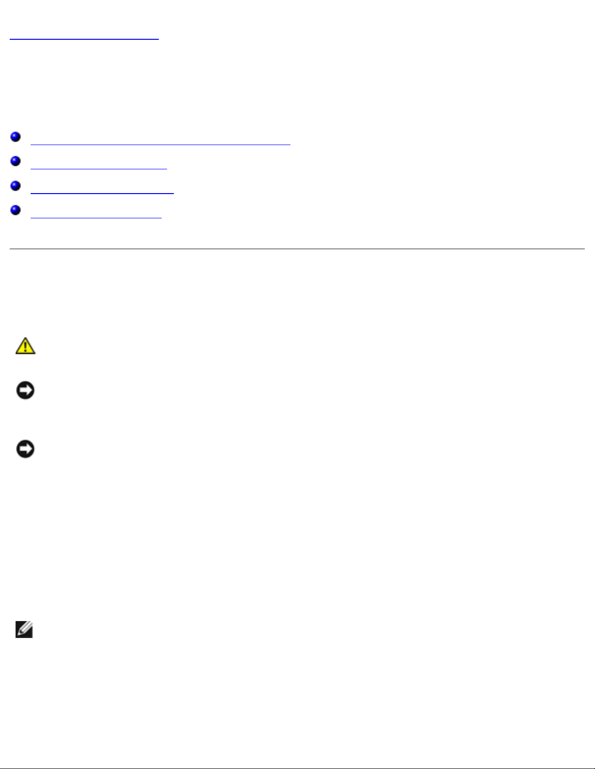
Computer Orientation
file:///F|/Service%20Manuals/Dell/Latitude/x200/begin.htm (2 of 6) [2/28/2004 8:23:54 AM]
Before You Begin: Dell Latitude X200 Service Manual
1 back
2 right
3 front
4 left
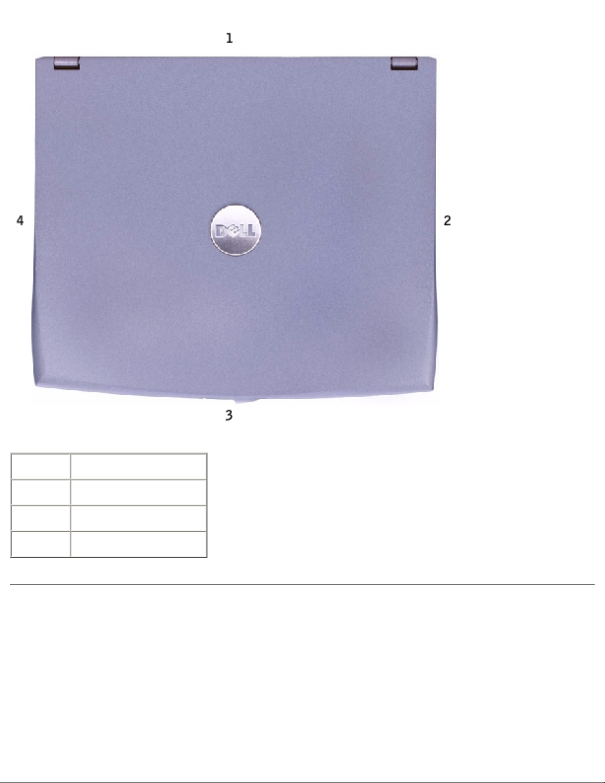
Screw Identification
When you are removing and replacing components, photocopy the placemat as a tool
to lay out and keep track of the screws. The placemat provides the number of screws
and their sizes.
file:///F|/Service%20Manuals/Dell/Latitude/x200/begin.htm (3 of 6) [2/28/2004 8:23:54 AM]
Before You Begin: Dell Latitude X200 Service Manual
NOTICE: When reinstalling a screw, you must use a screw of the correct
diameter and length. Ensure that the screw is properly aligned with its
corresponding hole, and avoid overtightening.
Keyboard:
(6 each)
Palm Rest:
(4 each)
Display Assembly:
(2 each)
Keyboard Tray:
(7 each)
file:///F|/Service%20Manuals/Dell/Latitude/x200/begin.htm (4 of 6) [2/28/2004 8:23:54 AM]
Before You Begin: Dell Latitude X200 Service Manual
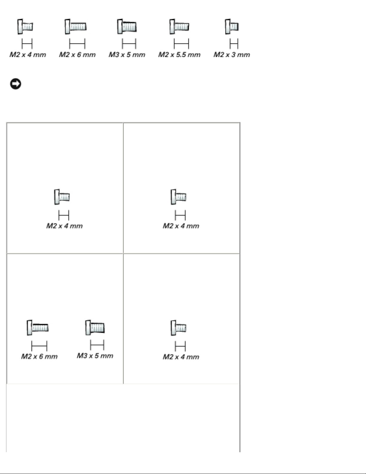
Hard Drive:
(3 each)
System Board:
(4 each)
Modem Daughter Card:
(1 each)
Cooling Fan:
(4 each)
Speaker:
(1 each)
Back to Contents Page
file:///F|/Service%20Manuals/Dell/Latitude/x200/begin.htm (5 of 6) [2/28/2004 8:23:54 AM]

Before You Begin: Dell Latitude X200 Service Manual
file:///F|/Service%20Manuals/Dell/Latitude/x200/begin.htm (6 of 6) [2/28/2004 8:23:54 AM]
System Components: Dell Latitude X200 Service Manual
Back to Contents Page
System Components
Dell™ Latitude™ X200 Service Manual
NOTICE: Only a certified service technician should perform repairs on your
computer. Damage due to servicing that is not authorized by Dell is not covered
by your warranty.
NOTICE: Unless otherwise noted, each procedure in this manual assumes that
a part can be replaced by performing the removal procedure in reverse order.
file:///F|/Service%20Manuals/Dell/Latitude/x200/system.htm (1 of 2) [2/28/2004 8:23:55 AM]
System Components: Dell Latitude X200 Service Manual
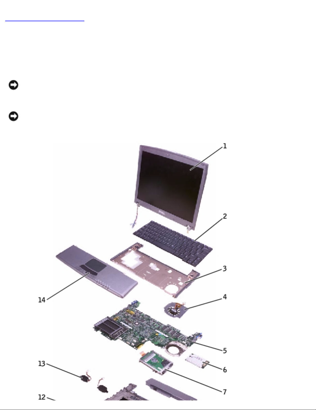
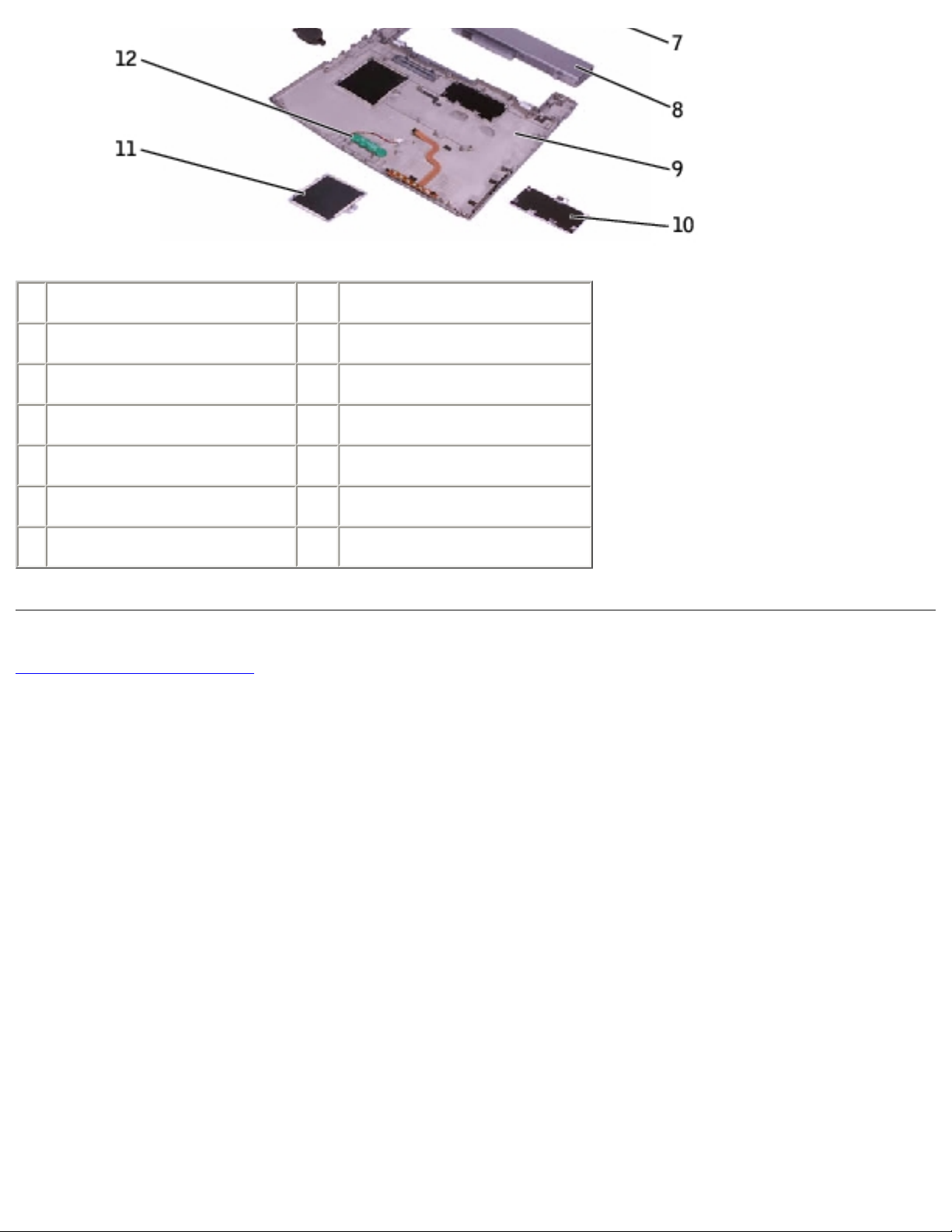
1 display 8 battery
2 keyboard 9 bottom case
3 keyboard tray 10 memory module cover
4 cooling fan 11 Mini PCI card cover
5 system board 12 reserve battery
6 modem daughter card 13 speakers (2)
7 hard drive 14 palm rest
Back to Contents Page
file:///F|/Service%20Manuals/Dell/Latitude/x200/system.htm (2 of 2) [2/28/2004 8:23:55 AM]

Battery: Dell Latitude X200 Service Manual
Back to Contents Page
Battery
Dell™ Latitude™ X200 Service Manual
Removing the Battery
NOTICE: If you choose to replace the battery with the computer in standby
mode, you have up to 1 minute to complete the battery replacement before the
computer shuts down and loses any unsaved data.
1. Ensure that the computer is turned off, suspended in a power management
mode, or connected to an electrical outlet.
2. If the computer is docked, undock it.
3. Slide the battery lock latch on the bottom of the computer to the unlock
position.
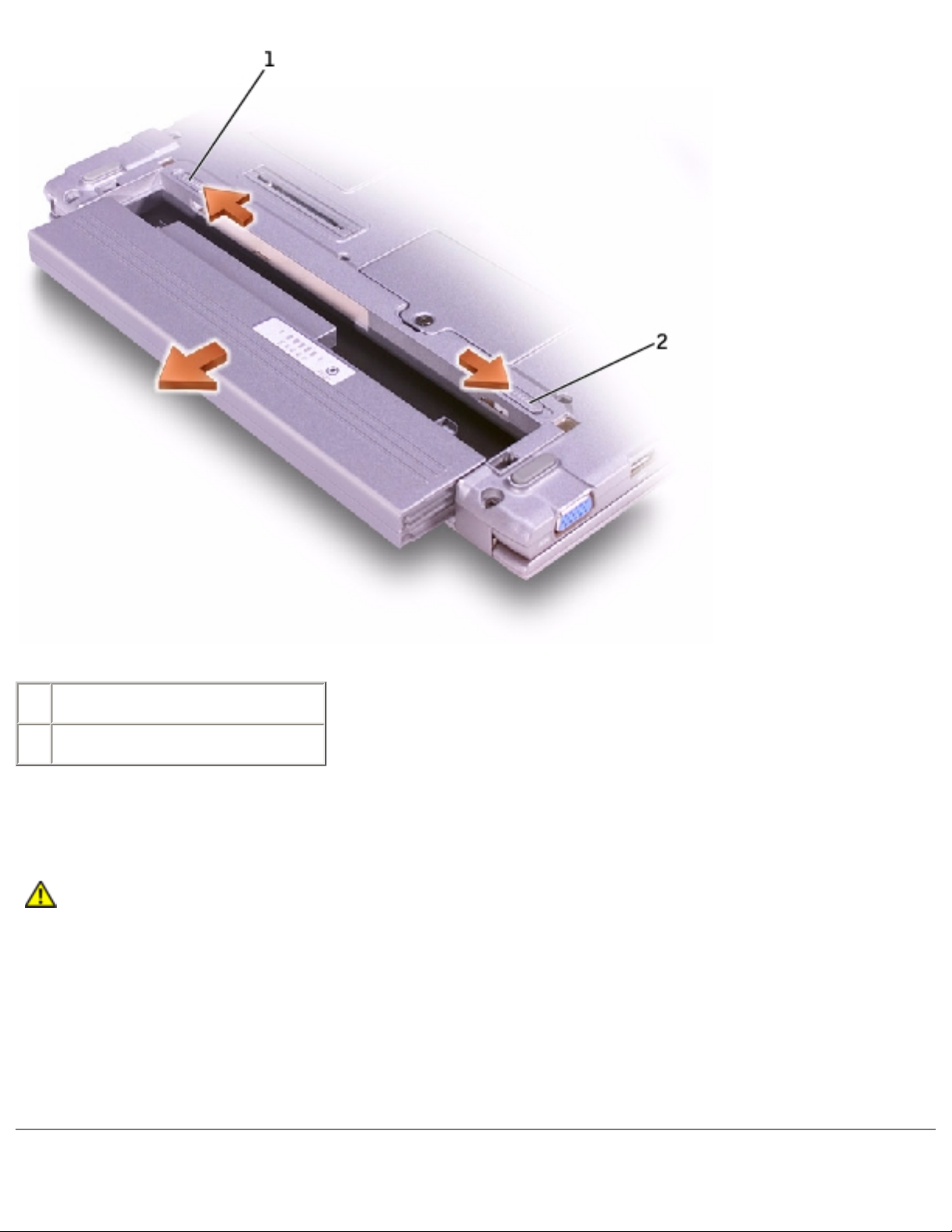
4. Slide and hold the battery latch release on the bottom of the computer, and
then remove the battery from the bay.
file:///F|/Service%20Manuals/Dell/Latitude/x200/battery.htm (1 of 3) [2/28/2004 8:23:56 AM]
Battery: Dell Latitude X200 Service Manual
1 battery lock latch
2 battery latch release
Replacing the Battery
CAUTION: Use only Dell™ battery modules that are approved for use
with this computer. Use of other types may increase the risk of fire or
explosion.
1. Slide the battery into the bay until the latch release clicks.
2. Slide the battery lock latch into the lock position.
file:///F|/Service%20Manuals/Dell/Latitude/x200/battery.htm (2 of 3) [2/28/2004 8:23:56 AM]

Battery: Dell Latitude X200 Service Manual
Back to Contents Page
file:///F|/Service%20Manuals/Dell/Latitude/x200/battery.htm (3 of 3) [2/28/2004 8:23:56 AM]

Memory Module and Mini PCI Card: Dell Latitude X200 Service Manual
Back to Contents Page
Memory Module and Mini PCI Card
Dell™ Latitude™ X200 Service Manual
Memory Module
Mini PCI Card
Memory Module
Removing the Memory Module Cover
NOTICE: Disconnect the computer and any attached devices from electrical
outlets, and remove any installed batteries.
NOTICE: To avoid ESD, ground yourself by using a wrist grounding strap or by
touching an unpainted metal surface on the computer.
NOTICE: Read "Preparing to Work Inside the Computer" before performing the
following procedure.
1. If the computer is docked, undock it.
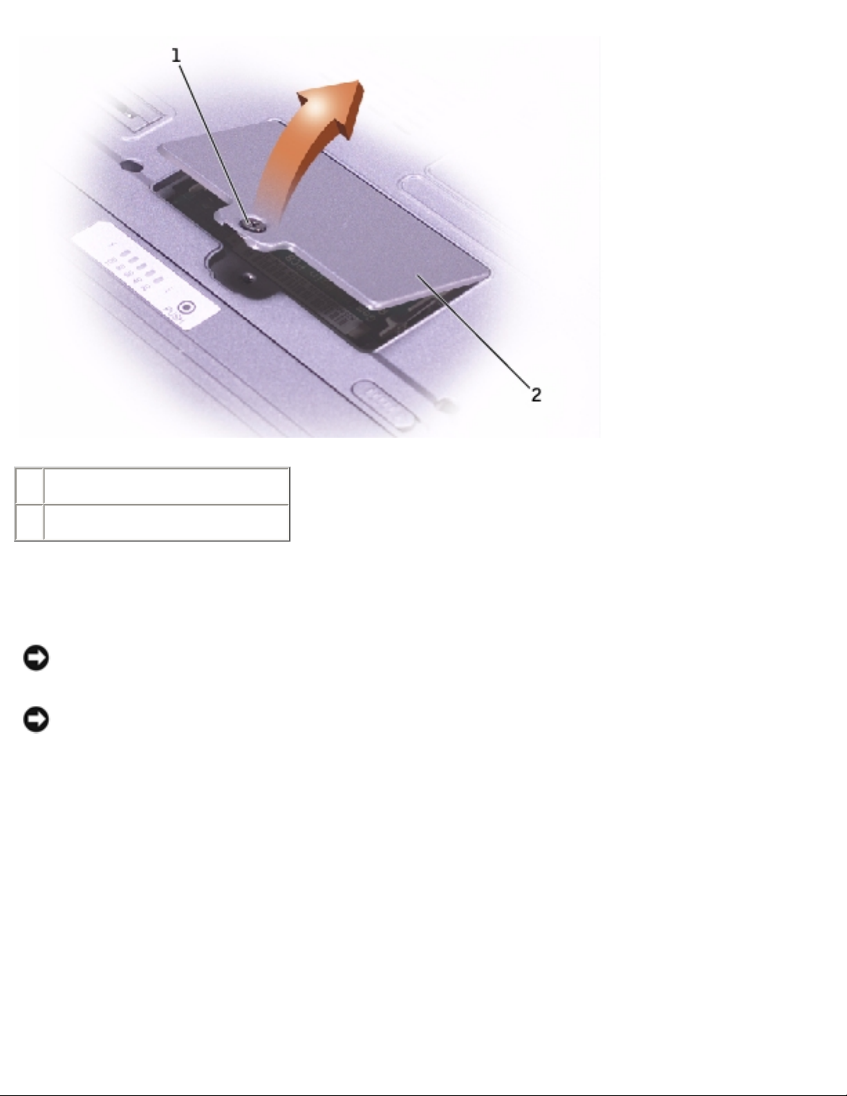
2. Turn the computer over, loosen the captive screw from the memory module
cover, and lift the cover.
file:///F|/Service%20Manuals/Dell/Latitude/x200/upgrades.htm (1 of 8) [2/28/2004 8:23:57 AM]
Memory Module and Mini PCI Card: Dell Latitude X200 Service Manual
1 captive screw
2 memory module cover
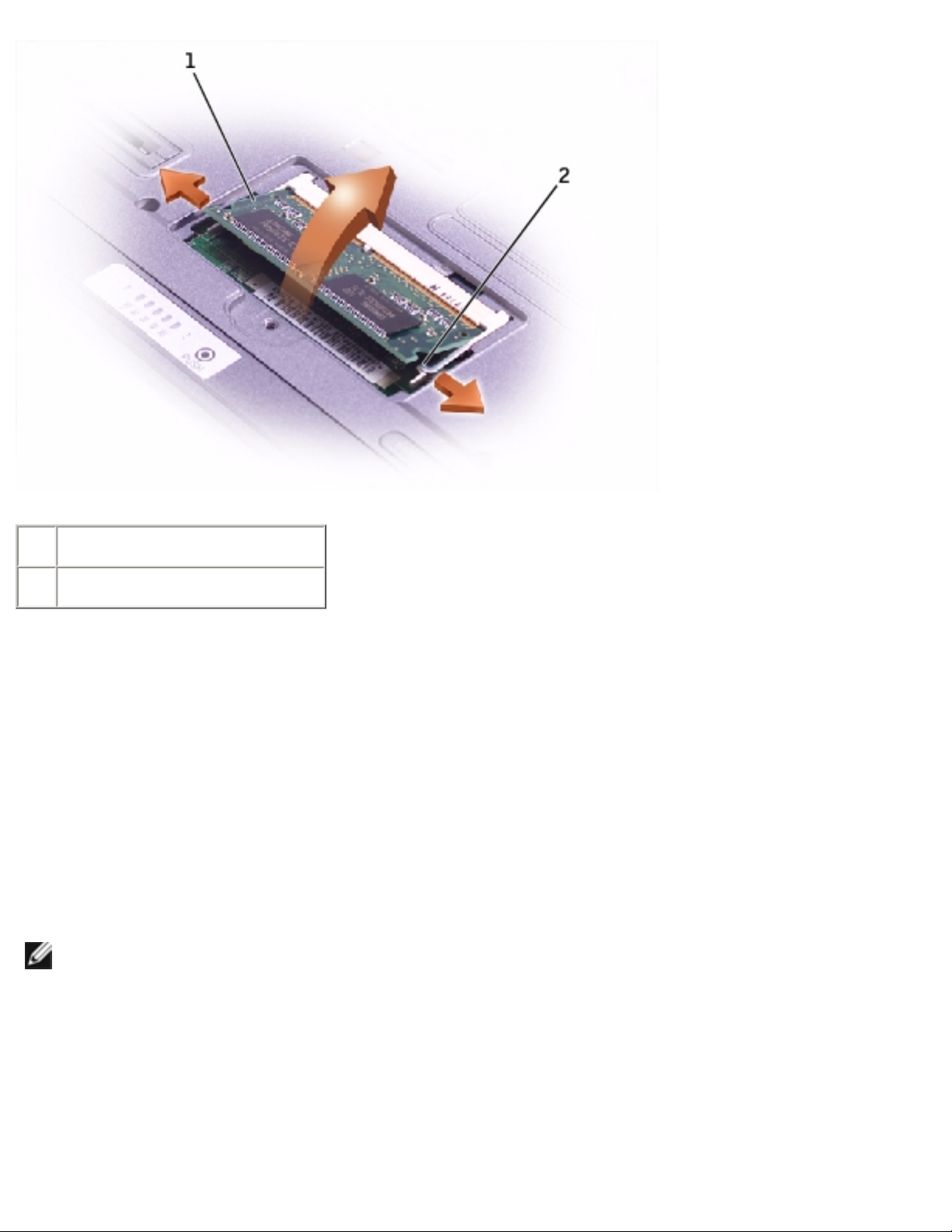
Removing the Memory Module
NOTICE: To prevent damage to the memory module connector, do not use
tools to spread the inner metal tabs that secure the memory module.
NOTICE: Handle memory modules by their edges, and do not touch the
components on a module.
1. Use your fingertips to spread apart the securing clips on each end of the
memory module connector.
The module should pop up.
2. Remove the module from the connector.
file:///F|/Service%20Manuals/Dell/Latitude/x200/upgrades.htm (2 of 8) [2/28/2004 8:23:57 AM]
Memory Module and Mini PCI Card: Dell Latitude X200 Service Manual
1 memory module
2 securing clips (2)
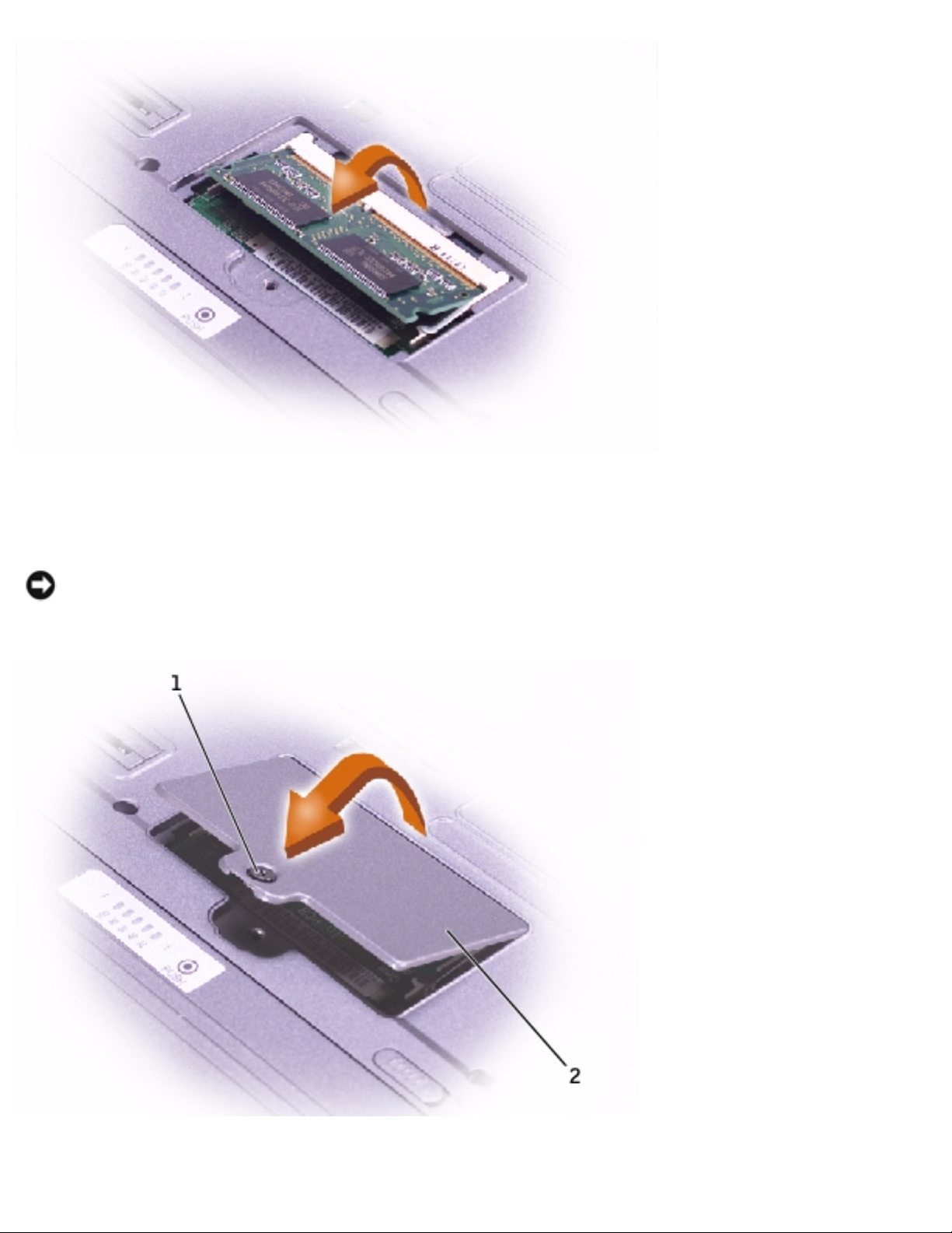
Replacing the Memory Module
1. Ground yourself and install the new memory module:
a. Align the notch in the module with the slot in the center of the connector.
b. Slide the edge of the module firmly into the connector, and rotate the
module down until you hear a click. If you do not hear the click, remove
the module and reinstall it.
NOTE: If the memory module is not installed properly, the computer does not
boot. No error message indicates this failure.
file:///F|/Service%20Manuals/Dell/Latitude/x200/upgrades.htm (3 of 8) [2/28/2004 8:23:57 AM]
Memory Module and Mini PCI Card: Dell Latitude X200 Service Manual
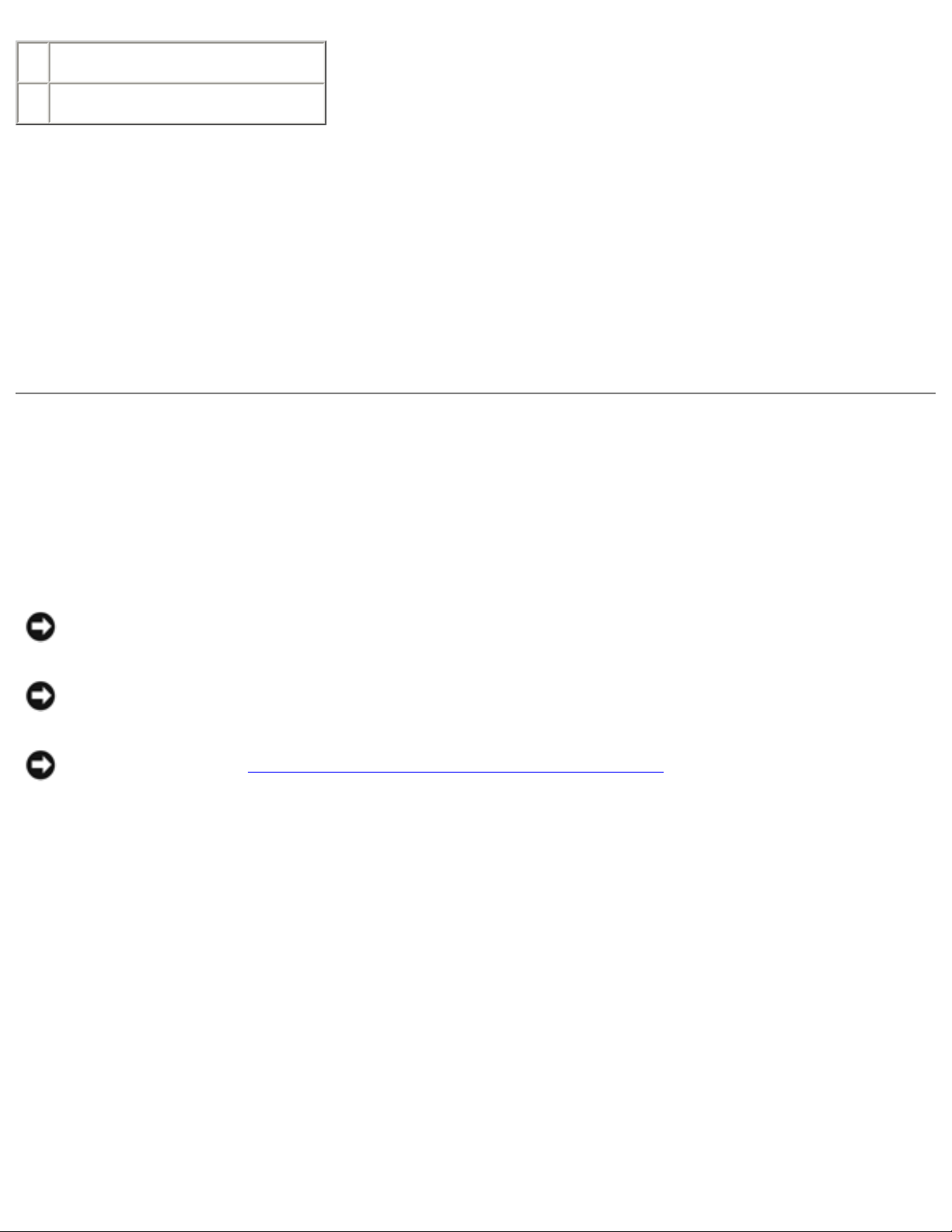
2. Replace the memory module cover and tighten the captive screw.
NOTICE: If the memory module cover is difficult to close, remove the module
and reinstall it. Forcing the cover to close may damage your computer.
file:///F|/Service%20Manuals/Dell/Latitude/x200/upgrades.htm (4 of 8) [2/28/2004 8:23:57 AM]
Memory Module and Mini PCI Card: Dell Latitude X200 Service Manual
1 captive screw
2 memory module cover
3. Insert the battery into the battery bay, or connect the AC adapter to your
computer and an electrical outlet.
4. Turn on the computer.
As the computer boots, it detects the additional memory and automatically updates
the system configuration information.
Mini PCI Card
Removing the Mini PCI Card Cover
NOTICE: Disconnect the computer and any attached devices from electrical
outlets, and remove any installed batteries.
NOTICE: To avoid ESD, ground yourself by using a wrist grounding strap or by
touching an unpainted metal surface on the computer.
NOTICE: Read "Preparing to Work Inside the Computer" before performing the
following procedure.
1. If the computer is docked, undock it.
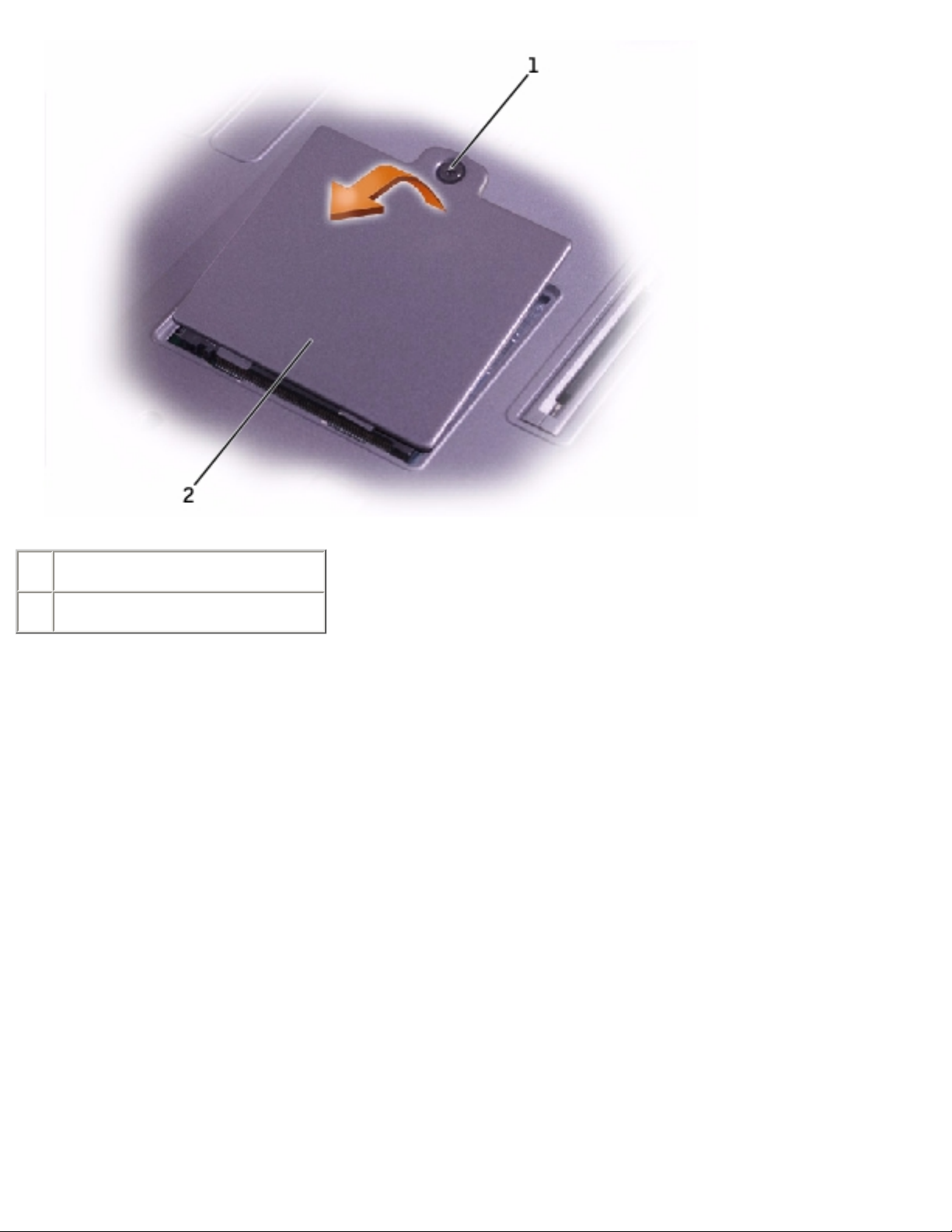
2. Turn the computer over, loosen the captive screw from the Mini PCI card cover,
and lift the cover.
file:///F|/Service%20Manuals/Dell/Latitude/x200/upgrades.htm (5 of 8) [2/28/2004 8:23:57 AM]
Memory Module and Mini PCI Card: Dell Latitude X200 Service Manual
1 captive screw
2 Mini PCI card cover
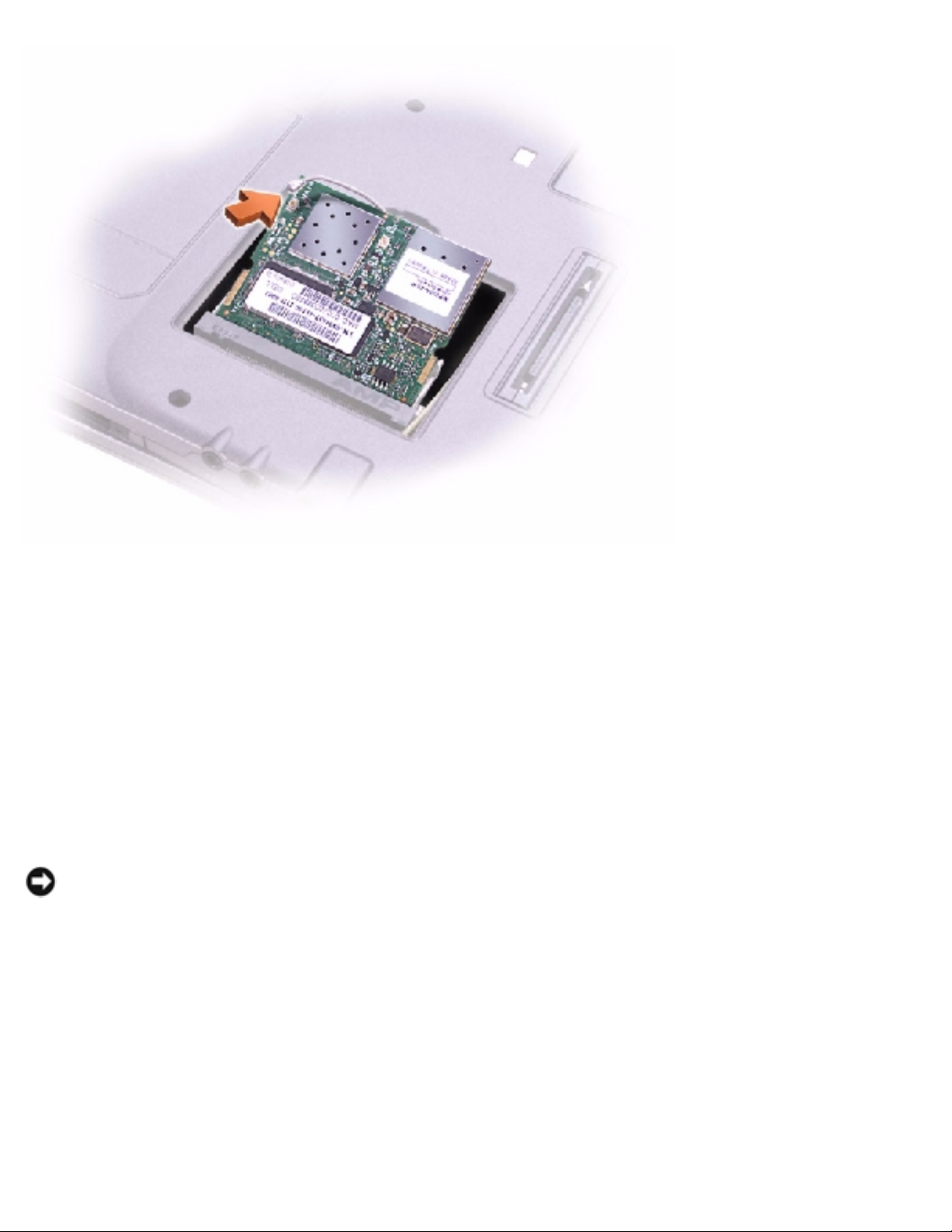
Removing the Mini PCI Card
1. Disconnect the antenna cable from the Mini PCI card.
2. Release the Mini PCI card by spreading the metal securing tabs until the card
pops up slightly.
3. Lift the Mini PCI card out of its connector.
file:///F|/Service%20Manuals/Dell/Latitude/x200/upgrades.htm (6 of 8) [2/28/2004 8:23:57 AM]
Memory Module and Mini PCI Card: Dell Latitude X200 Service Manual
Replacing the Mini PCI Card
1. Align the Mini PCI card with the connector at a 45-degree angle, and press the
Mini PCI card into the connector.
2. Connect the antenna cable to the antenna connector on the Mini PCI card.
NOTICE: The connectors are keyed for correct insertion; do not force the
connections.
3. Lower the Mini PCI card toward the inner tabs to approximately a 20-degree
angle.
4. Continue lowering the Mini PCI card until it snaps into the inner tabs of the
connector.
5. Replace the cover and tighten the captive screw.
file:///F|/Service%20Manuals/Dell/Latitude/x200/upgrades.htm (7 of 8) [2/28/2004 8:23:57 AM]

Memory Module and Mini PCI Card: Dell Latitude X200 Service Manual
Back to Contents Page
file:///F|/Service%20Manuals/Dell/Latitude/x200/upgrades.htm (8 of 8) [2/28/2004 8:23:57 AM]

Keyboard: Dell Latitude X200 Service Manual
Back to Contents Page
Keyboard
Dell™ Latitude™ X200 Service Manual
Removing the Keyboard
NOTICE: Disconnect the computer and any attached devices from electrical
outlets.
NOTICE: To avoid ESD, ground yourself by using a wrist grounding strap or by
touching an unpainted metal surface on the computer.
NOTICE: Read "Preparing to Work Inside the Computer" before performing the
following procedure.
1. Remove the
battery.
2. Remove the six M2 x 4-mm screws labeled with an arrow (one of the six screws
is labeled "K" with an arrow) from the bottom of the computer.
file:///F|/Service%20Manuals/Dell/Latitude/x200/keyboard.htm (1 of 6) [2/28/2004 8:23:58 AM]

Keyboard: Dell Latitude X200 Service Manual
1 M2 x 4-mm screws (6)
NOTICE: The keycaps on the keyboard are fragile, easily dislodged, and time-
consuming to replace. Be careful when removing and handling the keyboard.
3. Turn the computer over, and insert a ¼-inch flat-blade screwdriver into the slot
to the right of the keyboard locator tab.
file:///F|/Service%20Manuals/Dell/Latitude/x200/keyboard.htm (2 of 6) [2/28/2004 8:23:58 AM]

Keyboard: Dell Latitude X200 Service Manual
1 keyboard locator tab
2 keyboard securing tabs
(4)
4. Pry up the keyboard locator tab, and the keyboard pops up.
file:///F|/Service%20Manuals/Dell/Latitude/x200/keyboard.htm (3 of 6) [2/28/2004 8:23:58 AM]

Keyboard: Dell Latitude X200 Service Manual
5. Pull the keyboard a small distance toward the front of the computer to release
the four securing tabs located across the back edge of the keyboard.
6. Rotate the keyboard toward the front of the computer and place it face-down on
the palm rest.
NOTICE: Do not pull on the keyboard flex cable.
7. Open the ZIF connector on the system board by pulling the ZIF connector tabs
toward the back of the computer.
1 keyboard flex cable
2 ZIF connector
3 ZIF connector tabs (2)
8. Remove the keyboard flex cable from the ZIF connector.
9. Lift the keyboard up and out of the computer.
file:///F|/Service%20Manuals/Dell/Latitude/x200/keyboard.htm (4 of 6) [2/28/2004 8:23:58 AM]

Keyboard: Dell Latitude X200 Service Manual
Replacing the Keyboard
1. Place the keyboard face-down on the palm rest, with the keyboard flex cable
pointing toward the back of the computer.
NOTICE: To avoid damage to the connector pins, insert the keyboard flex cable
evenly into the ZIF connector on the system board, and do not reverse the
keyboard flex cable.
2. Ensure that the ZIF connector is open by pulling the ZIF connector tabs toward
the back of the computer.
3. Press the keyboard flex cable into the ZIF connector.
4. Close the ZIF connector by pushing the ZIF connector tabs toward the front of
the computer.
To aid with proper flex cable connection, a blue locator line has been added near
the end of the flex cable. Press the cable into the connector until the blue line
disappears and hold the cable steady while you close the ZIF connector. (The blue
line may reappear after the connector is closed, which should not indicate a
problem with the connection.)
NOTICE: Position the keyboard flex cable so that it is not pinched when you
replace the keyboard in the bottom case.
5. Rotate the keyboard back and fit it into the bottom case.
6. Ensure that all four keyboard securing tabs are engaged in their respective slots
before trying to completely seat the keyboard. Press down on the left and right
keys to help control tab/slot alignment.
When the keyboard appears to be completely seated, confirm that the front edge
of the keyboard is aligned with the edge of the palm rest before proceeding.
7. Replace the six M2 x 4-mm screws on the bottom of the computer.
file:///F|/Service%20Manuals/Dell/Latitude/x200/keyboard.htm (5 of 6) [2/28/2004 8:23:58 AM]

Keyboard: Dell Latitude X200 Service Manual
Back to Contents Page
file:///F|/Service%20Manuals/Dell/Latitude/x200/keyboard.htm (6 of 6) [2/28/2004 8:23:58 AM]

Palm Rest: Dell Latitude X200 Service Manual
Back to Contents Page
Palm Rest
Dell™ Latitude™ X200 Service Manual
Removing the Palm Rest
NOTICE: Disconnect the computer and any attached devices from electrical
outlets.
NOTICE: To avoid ESD, ground yourself by using a wrist grounding strap or by
touching an unpainted metal surface on the computer.
NOTICE: Read "Preparing to Work Inside the Computer" before performing the
following procedure.
1. Remove the
battery.
2. Remove the
keyboard.
3. Turn the computer over, and remove the four M2 x 4-mm screws from the
bottom of the computer.
file:///F|/Service%20Manuals/Dell/Latitude/x200/palmrest.htm (1 of 4) [2/28/2004 8:23:59 AM]

Palm Rest: Dell Latitude X200 Service Manual
1 M2 x 4-mm screws (4)
4. Turn the computer over, and open the display (if you have not already removed
the display).
5. Lift the back edge of the palm rest, and rotate the palm rest forward.
6. Lift the ZIF connector, and disconnect the palm-rest flex cable from its ZIF
connector on the system board.
file:///F|/Service%20Manuals/Dell/Latitude/x200/palmrest.htm (2 of 4) [2/28/2004 8:23:59 AM]

Palm Rest: Dell Latitude X200 Service Manual
1 palm-rest flex cable
2 ZIF connector
7. Lift the palm rest up and out of the computer.
Replacing the Palm Rest
To aid with proper flex cable connection, a blue locator line has been added near the
end of the palm-rest flex cable. When replacing the palm-rest flex cable, press the
cable into the connector until the blue line aligns with the system board and hold it
steady while you snap the ZIF connector down. (The blue line may reappear after the
connector is closed, which should not indicate a problem with the connection.)
Back to Contents Page
file:///F|/Service%20Manuals/Dell/Latitude/x200/palmrest.htm (3 of 4) [2/28/2004 8:23:59 AM]

Palm Rest: Dell Latitude X200 Service Manual
file:///F|/Service%20Manuals/Dell/Latitude/x200/palmrest.htm (4 of 4) [2/28/2004 8:23:59 AM]

Hard Drive: Dell Latitude X200 Service Manual
Back to Contents Page
Hard Drive
Dell™ Latitude™ X200 Service Manual
Removing the Hard Drive
NOTICE: Disconnect the computer and any attached devices from electrical
outlets.
NOTICE: To avoid ESD, ground yourself by using a wrist grounding strap or by
touching an unpainted metal surface on the computer.
NOTICE: Read "Preparing to Work Inside the Computer" before performing the
following procedure.
1. Remove the
battery.
2. Remove the
keyboard.
3. Remove the
palm rest.
4. Loosen the three M2 x 5.5-mm screws that secure the hard drive to the bottom
case.
Rubber grommets secure each screw to the hard drive so that you do not need to
completely remove the screws.
NOTE: Each hard drive screw has an arrow beside it.
file:///F|/Service%20Manuals/Dell/Latitude/x200/hdd.htm (1 of 2) [2/28/2004 8:24:00 AM]

Hard Drive: Dell Latitude X200 Service Manual
1 hard drive
2 M2 x 5.5-mm screws (3)
3 hard drive connector
5. Disconnect the hard drive connector from the system board.
6. Lift the hard drive up and out of the bottom case.
Back to Contents Page
file:///F|/Service%20Manuals/Dell/Latitude/x200/hdd.htm (2 of 2) [2/28/2004 8:24:00 AM]

Hinge Covers and Display Assembly: Dell Latitude X200 Service Manual
Back to Contents Page
Hinge Covers and Display Assembly
Dell™ Latitude™ X200 Service Manual
Hinge Covers
Display Assembly
Hinge Covers
Removing the Hinge Covers
1. Remove the battery.
2. On the inside of the battery bay, use your fingers to unhook the hinge covers
from the back of the computer.
file:///F|/Service%20Manuals/Dell/Latitude/x200/display.htm (1 of 7) [2/28/2004 8:24:01 AM]

Hinge Covers and Display Assembly: Dell Latitude X200 Service Manual
1 hinge covers (2)
3. Open the display 180 degrees.
4. Push up on the hinge covers to remove them from the computer.
Replacing the Hinge Covers
1. Open the computer all the way (180 degrees) so that it lies flat against your
work surface.
2. Place the hinge covers over the display hinges:
a. The left hinge cover fits over the power button and the right hinge cover
fits over the Dell™ AccessDirect™ button. Both hinge covers pass through
the display hinges to the back of the computer.
b. Ensure that the two securing tabs on the outer edge of each hinge cover
are engaged in their respective slots.
3. Press down on the top of each hinge cover to snap the hinge covers into place.
4. Close the display.
5. Press the back of each hinge cover into the back of the computer.
NOTE: The back of each hinge cover has a tab that snaps into a slot on the
back of the computer.
Display Assembly
Removing the Display Assembly
NOTICE: Disconnect the computer and any attached devices from electrical
outlets.
file:///F|/Service%20Manuals/Dell/Latitude/x200/display.htm (2 of 7) [2/28/2004 8:24:01 AM]

Hinge Covers and Display Assembly: Dell Latitude X200 Service Manual
NOTICE: To avoid ESD, ground yourself by using a wrist grounding strap or by
touching an unpainted metal surface on the computer.
NOTICE: Read "Preparing to Work Inside the Computer" before performing the
following procedure.
1. Remove the
battery.
2. Remove the
keyboard.
3. Remove the two M2 x 6-mm screws by the display hinges on the top of the
computer.
1 M2 x 6-mm screws (2)
4. Turn the computer over, and remove the two M3 x 5-mm screws from the
bottom of the computer.
file:///F|/Service%20Manuals/Dell/Latitude/x200/display.htm (3 of 7) [2/28/2004 8:24:01 AM]

Hinge Covers and Display Assembly: Dell Latitude X200 Service Manual
1 M3 x 5-mm screws (2)
5. Turn the computer over, and open the display 180 degrees.
6. Disconnect the antenna connector.
file:///F|/Service%20Manuals/Dell/Latitude/x200/display.htm (4 of 7) [2/28/2004 8:24:01 AM]

Hinge Covers and Display Assembly: Dell Latitude X200 Service Manual
NOTICE: Do not pull on the signal cable and inverter cable. Pull from the signal
connector and inverter connector to disconnect the cables.
7. Disconnect the signal cable from the system board.
8. Remove the tape that secures the inverter connector, and then disconnect the
inverter cable from the system board.
file:///F|/Service%20Manuals/Dell/Latitude/x200/display.htm (5 of 7) [2/28/2004 8:24:01 AM]

Hinge Covers and Display Assembly: Dell Latitude X200 Service Manual
1 signal cable
2 inverter cable
3 inverter connector
4 signal connector
9. Move the display assembly to an upright position and pull it up out of the
bottom case.
Back to Contents Page
file:///F|/Service%20Manuals/Dell/Latitude/x200/display.htm (6 of 7) [2/28/2004 8:24:01 AM]

Hinge Covers and Display Assembly: Dell Latitude X200 Service Manual
file:///F|/Service%20Manuals/Dell/Latitude/x200/display.htm (7 of 7) [2/28/2004 8:24:01 AM]

Keyboard Tray: Dell Latitude X200 Service Manual
Back to Contents Page
Keyboard Tray
Dell™ Latitude™ X200 Service Manual
Removing the Keyboard Tray
NOTICE: Disconnect the computer and any attached devices from electrical
outlets.
NOTICE: To avoid ESD, ground yourself by using a wrist grounding strap or by
touching an unpainted metal surface on the computer.
NOTICE: Read "Preparing to Work Inside the Computer" before performing the
following procedure.
1. Remove the
battery.
2. Remove the
keyboard.
3. Remove the
palm rest.
4. Remove the
hinge covers.
5. Remove the
display assembly.
6. Remove the seven M2 x 4-mm screws that secure the keyboard tray to the
system board.
NOTE: Each keyboard tray screw has an arrow beside it.
file:///F|/Service%20Manuals/Dell/Latitude/x200/keytray.htm (1 of 3) [2/28/2004 8:24:02 AM]

Keyboard Tray: Dell Latitude X200 Service Manual
1 keyboard tray
2 M2 x 4-mm screws (7)
7. Lift the keyboard tray up and out of the bottom case.
NOTE: The air vent on the right side of the computer comes loose when the
keyboard tray is removed.
Replacing the Keyboard Tray
1. Replace the air vent:
a. Align the two pin holes on the bottom of the air vent with the pins on the
bottom case by the cooling fan.
b. Slide the air vent into the bottom case.
file:///F|/Service%20Manuals/Dell/Latitude/x200/keytray.htm (2 of 3) [2/28/2004 8:24:02 AM]

Keyboard Tray: Dell Latitude X200 Service Manual
1 air vent
2 pin holes (2)
2. Replace the keyboard tray.
3. Reinstall the seven M2 x 4-mm screws that secure the keyboard tray to the
system board.
Back to Contents Page
file:///F|/Service%20Manuals/Dell/Latitude/x200/keytray.htm (3 of 3) [2/28/2004 8:24:02 AM]

Reserve Battery: Dell Latitude X200 Service Manual
Back to Contents Page
Reserve Battery
Dell™ Latitude™ X200 Service Manual
Removing the Reserve Battery
NOTICE: Disconnect the computer and any attached devices from electrical
outlets.
NOTICE: To avoid ESD, ground yourself by using a wrist grounding strap or by
touching an unpainted metal surface on the computer.
NOTICE: Read "Preparing to Work Inside the Computer" before performing the
following procedure.
1. Remove the
battery.
2. Remove the
keyboard.
3. Remove the
palm rest.
NOTICE: Do not pull on the reserve battery cable. Pull from the reserve battery
connector to disconnect the cable.
4. Disconnect the reserve battery cable from the system board connector.
file:///F|/Service%20Manuals/Dell/Latitude/x200/rsrvbatt.htm (1 of 3) [2/28/2004 8:24:02 AM]

Reserve Battery: Dell Latitude X200 Service Manual
1 reserve battery cable
2 system board connector
3 reserve battery
connector
4 reserve battery
5. Pry the reserve battery free from the bottom case. The reserve battery is
attached to the bottom case with a piece of adhesive tape.
6. Remove any remnants of the adhesive tape from the bottom case.
Replacing the Reserve Battery
1. Connect the reserve battery connector to the system board connector.
2. Press the reserve battery into place on the bottom case.
3. Update the BIOS using a flash BIOS update program. For instructions on how to
flash the BIOS, see "Flashing the BIOS."
file:///F|/Service%20Manuals/Dell/Latitude/x200/rsrvbatt.htm (2 of 3) [2/28/2004 8:24:02 AM]

Reserve Battery: Dell Latitude X200 Service Manual
Back to Contents Page
file:///F|/Service%20Manuals/Dell/Latitude/x200/rsrvbatt.htm (3 of 3) [2/28/2004 8:24:02 AM]

Speakers: Dell Latitude X200 Service Manual
Back to Contents Page
Speakers
Dell™ Latitude™ X200 Service Manual
Removing the Speakers
NOTICE: Disconnect the computer and any attached devices from electrical
outlets.
NOTICE: To avoid ESD, ground yourself by using a wrist grounding strap or by
touching an unpainted metal surface on the computer.
NOTICE: Read "Preparing to Work Inside the Computer" before performing the
following procedure.
1. Remove the
battery.
2. Remove the
keyboard.
3. Remove the
palm rest.
4. Remove the M2 x 4-mm screw that secures the speaker to the bottom case.
NOTE: The left and right speakers are interchangeable.
file:///F|/Service%20Manuals/Dell/Latitude/x200/speakers.htm (1 of 3) [2/28/2004 8:24:03 AM]

Speakers: Dell Latitude X200 Service Manual
1 system board connector
(1 per speaker)
2 speaker connector
(1 per speaker)
3 M2 x 4-mm screw
(1 per speaker)
4 speaker cable
(1 per speaker)
5 speakers (2)
NOTICE: Do not pull on the speaker cable. Pull from the speaker connector to
disconnect the cable.
5. Disconnect the speaker cable from the system board connector.
NOTICE: Handle the speakers with care to avoid damaging them.
6. Remove the speaker by pulling it straight up and out of the bottom case.
file:///F|/Service%20Manuals/Dell/Latitude/x200/speakers.htm (2 of 3) [2/28/2004 8:24:03 AM]

Speakers: Dell Latitude X200 Service Manual
Back to Contents Page
file:///F|/Service%20Manuals/Dell/Latitude/x200/speakers.htm (3 of 3) [2/28/2004 8:24:03 AM]

Cooling Fan: Dell Latitude X200 Service Manual
Back to Contents Page
Cooling Fan
Dell™ Latitude™ X200 Service Manual
Removing the Cooling Fan
NOTICE: Disconnect the computer and any attached devices from electrical
outlets.
NOTICE: To avoid ESD, ground yourself by using a wrist grounding strap or by
touching an unpainted metal surface on the computer.
NOTICE: Read "Preparing to Work Inside the Computer" before performing the
following procedure.
1. Remove the
battery.
2. Remove the
keyboard.
3. Remove the
palm rest.
4. Remove the
hinge covers.
5. Remove the
display assembly.
6. Remove the
keyboard tray.
7. Remove the four M2 x 3-mm screws that secure the cooling fan to the system
board.
file:///F|/Service%20Manuals/Dell/Latitude/x200/fan.htm (1 of 3) [2/28/2004 8:24:04 AM]

Cooling Fan: Dell Latitude X200 Service Manual
1 cooling fan connector
2 cooling fan cable
3 cooling fan
4 M2 x 3-mm screws (4)
5 system board connector
8. Remove the tape that secures the cooling fan cable to the fan.
NOTICE: Do not pull on the cooling fan cable. Pull from the cooling fan
connector to disconnect the cable.
9. Disconnect the cooling fan cable from the system board connector.
file:///F|/Service%20Manuals/Dell/Latitude/x200/fan.htm (2 of 3) [2/28/2004 8:24:04 AM]

Cooling Fan: Dell Latitude X200 Service Manual
10. Lift the cooling fan up and out of the bottom case.
Back to Contents Page
file:///F|/Service%20Manuals/Dell/Latitude/x200/fan.htm (3 of 3) [2/28/2004 8:24:04 AM]

System Board: Dell Latitude X200 Service Manual
Back to Contents Page
System Board
Dell™ Latitude™ X200 Service Manual
Removing the System Board
NOTICE: Disconnect the computer and any attached devices from electrical
outlets.
NOTICE: To avoid ESD, ground yourself by using a wrist grounding strap or by
touching an unpainted metal surface on the computer.
NOTICE: Read "Preparing to Work Inside the Computer" before performing the
following procedure.
1. Remove the
battery.
2. Remove the
keyboard.
3. Remove the
palm rest.
4. Remove the
hinge covers.
5. Remove the
display assembly.
6. Remove the
keyboard tray.
7. Remove the
hard drive.
8. Remove the
memory module.
9. Remove the
Mini PCI card, if present.
10. Remove the four M2 x 4-mm screws that secure the system board to the bottom
case.
NOTE: Each system board screw has an arrow beside it.
file:///F|/Service%20Manuals/Dell/Latitude/x200/sysboard.htm (1 of 3) [2/28/2004 8:24:04 AM]

System Board: Dell Latitude X200 Service Manual
1 system board
2 M2 x 4-mm screws (4)
3 status light (LED) cable
4 ZIF connector
11. Disconnect the
left and right speakers from their system board connectors.
12. Disconnect the
reserve battery connector from the system board connector.
13. Lift the ZIF connector, and remove the status light (LED) cable from its ZIF
connector on the system board.
14. Lift the system board up and out of the bottom case.
file:///F|/Service%20Manuals/Dell/Latitude/x200/sysboard.htm (2 of 3) [2/28/2004 8:24:04 AM]

System Board: Dell Latitude X200 Service Manual
15. Remove the modem daughter card, and set it aside to install in the replacement
system board.
Replacing the System Board
1. Install the modem daughter card that you removed from the old system board
in the replacement system board.
2. Place the system board in the bottom case.
NOTE: Route cables so that they will not be crimped or pinched when the
complete assembly is put back together.
3. Reconnect the status light (LED) cable to the system board ZIF connector.
4. Reinstall the four M2 x 4-mm screws that secure the system board to the
bottom case.
NOTE: After replacing the system board, enter the computer service tag
sequence into the BIOS of the replacement system board.
Back to Contents Page
file:///F|/Service%20Manuals/Dell/Latitude/x200/sysboard.htm (3 of 3) [2/28/2004 8:24:04 AM]

Modem Daughter Card: Dell Latitude X200 Service Manual
Back to Contents Page
Modem Daughter Card
Dell™ Latitude™ X200 Service Manual
Removing the Modem Daughter Card
NOTICE: Disconnect the computer and any attached devices from electrical
outlets.
NOTICE: To avoid ESD, ground yourself by using a wrist grounding strap or by
touching an unpainted metal surface on the computer.
NOTICE: Read "Preparing to Work Inside the Computer" before performing the
following procedure.
1. Remove the
battery.
2. Remove the
keyboard.
3. Remove the
palm rest.
4. Remove the
hinge covers.
5. Remove the
display assembly.
6. Remove the
keyboard tray.
7. Remove the
hard drive.
8. Remove the
system board.
9. Turn the system board over, and remove the M2 x 4-mm screw that secures the
modem daughter card to the system board.
10. Use the pull tab to pull the modem daughter card straight up out of its
connector.
file:///F|/Service%20Manuals/Dell/Latitude/x200/modem.htm (1 of 3) [2/28/2004 8:24:05 AM]

Modem Daughter Card: Dell Latitude X200 Service Manual
NOTICE: Do not pull on the modem cable. Pull from the modem connector to
disconnect the cable.
11. Disconnect the modem cable from the modem daughter card.
1 modem daughter card
2 modem connector
3 modem cable
4 pull tab
5 M2 x 4-mm screw
Replacing the Modem Daughter Card
1. Connect the modem cable to the modem.
file:///F|/Service%20Manuals/Dell/Latitude/x200/modem.htm (2 of 3) [2/28/2004 8:24:05 AM]

Modem Daughter Card: Dell Latitude X200 Service Manual
NOTICE: The connectors are keyed for correct insertion; do not force the
connections.
2. Align the modem with the screw hole and press the modem into the connector
on the system board.
3. Use the screw hole to align the card, and press the card into its connector on
the system board.
4. Install the M2 x 4-mm screw that secures the modem to the system board.
Back to Contents Page
file:///F|/Service%20Manuals/Dell/Latitude/x200/modem.htm (3 of 3) [2/28/2004 8:24:05 AM]

Battery Latches: Dell Latitude X200 Service Manual
Back to Contents Page
Battery Latches
Dell™ Latitude™ X200 Service Manual
Removing the Battery Latches
NOTICE: Disconnect the computer and any attached devices from electrical
outlets.
NOTICE: To avoid ESD, ground yourself by using a wrist grounding strap or by
touching an unpainted metal surface on the computer.
NOTICE: Read "Preparing to Work Inside the Computer" before performing the
following procedure.
1. Remove the
battery.
2. Remove the
keyboard.
3. Remove the
palm rest.
4. Remove the
hinge covers.
5. Remove the
display assembly.
6. Remove the
keyboard tray.
7. Remove the
hard drive.
8. Remove the
memory module.
9. Remove the
Mini PCI card, if present.
10. Remove the
system board.
11. On the inside of the bottom case, use your fingers to unhook the latch from the
bottom case and the snap tabs, catching the latch button on the outside of the
bottom case.
file:///F|/Service%20Manuals/Dell/Latitude/x200/batlatch.htm (1 of 3) [2/28/2004 8:24:06 AM]

Battery Latches: Dell Latitude X200 Service Manual
1 battery lock latch
2 snap tabs (3 per latch
button)
3 battery latch release
4 spring
5 bottom case
Replacing the Battery Latches
1. Snap in the new latch button from behind the bottom case, making certain that
the snap tabs are fully engaged in the latch.
NOTE: The battery latch release has a spring and should be installed on the
right side of the bottom case.
2. Ensure that the newly installed latch moves smoothly and freely when pushed
and released.
file:///F|/Service%20Manuals/Dell/Latitude/x200/batlatch.htm (2 of 3) [2/28/2004 8:24:06 AM]

Battery Latches: Dell Latitude X200 Service Manual
Back to Contents Page
file:///F|/Service%20Manuals/Dell/Latitude/x200/batlatch.htm (3 of 3) [2/28/2004 8:24:06 AM]

Flashing the BIOS: Dell Latitude X200 Service Manual
Back to Contents Page
Flashing the BIOS
Dell™ Latitude™ X200 Service Manual
To update the basic input/output system (BIOS):
1. Go to support.dell.com. If this is your first time to use the website, complete
the one-time registration.
2. Enter the service tag sequence for your computer or select the appropriate
Dell™ computer.
Click Go.
3. Click Downloads.
4. Select the appropriate operating system and language for your computer.
5. Select the FlashBIOS Updates download category.
Click Go.
6. Click the BIOS link and follow the instructions to download the BIOS to your
computer.
Back to Contents Page
file:///F|/Service%20Manuals/Dell/Latitude/x200/bios.htm [2/28/2004 8:24:06 AM]

Pin Assignments for I/O Connectors: Dell Latitude X200 Service Manual
Back to Contents Page
Pin Assignments for I/O Connectors
Dell™ Latitude™ X200 Service Manual
Pin Assignments for the Computer
Pin Assignments for the Media Base
Pin Assignments for the Computer
USB Connector
Pin Signal
1 VCC
2 -Data
3 +Data
4 Ground
Video Connector
file:///F|/Service%20Manuals/Dell/Latitude/x200/pinouts.htm (1 of 10) [2/28/2004 8:24:07 AM]

Pin Assignments for I/O Connectors: Dell Latitude X200 Service Manual
Pin Signal Pin Signal
1 RED 9 CRT_VCC
2 GREEN 10 GND
3 BLUE 11 NC
4 NC 12 DAT_DDC2
5 GND 13 HSYNC
6 GND 14 VSYNC
7 GND 15 CLK_DDC2
8 GND
IEEE 1394 Connector
file:///F|/Service%20Manuals/Dell/Latitude/x200/pinouts.htm (2 of 10) [2/28/2004 8:24:07 AM]

Pin Assignments for I/O Connectors: Dell Latitude X200 Service Manual
1 TPA2 TPB3 P12V
4 GND
5 TPB+
6 TPA+
Pin Assignments for the Media Base
Docking Connector
file:///F|/Service%20Manuals/Dell/Latitude/x200/pinouts.htm (3 of 10) [2/28/2004 8:24:07 AM]

Pin Assignments for I/O Connectors: Dell Latitude X200 Service Manual
Pin Signal Pin Signal
1 DCK3_DOCK_IN2 51 P3.3V_LAN
2 KBC3_DCKRST 52 FDD3_STEP
3 ADID 53 PS25_KCLK
4 DCK_DCIN 54 FDD3_WGATE
5 PIO3_STROBE 55 PS25_KDATA
6 VGA3_RED 56 FDD3_WP
7 PIO3_ACK 57 PS25_MCLK
8 VGA3_GREEN 58 FDD3_HDSEL
9 PIO3_BUSY 59 PS25_MDATA
10 VGA3_BLUE 60 NC
11 PIO3_PE 61 SIO3_DTR1
12 VGA5_DDCD 62 1394_TPB13 NC 63 SIO3_TXD1
14 VGA5_DDCC 64 1394_TPB+
15 PIO3_SLCT 65 SIO3_RTS1
16 VGA5_HSYNC 66 NC
17 PIO3_AUTOFD 67 NC
file:///F|/Service%20Manuals/Dell/Latitude/x200/pinouts.htm (4 of 10) [2/28/2004 8:24:07 AM]

Pin Assignments for I/O Connectors: Dell Latitude X200 Service Manual
18 VGA5_VSYNC 68 1394_TPA19 PIO3_ERROR 69 SIO3_CTS1
20 NC 70 1394_TPA+
21 PIO3_INIT 71 SIO3_RI1
22 KBC3_EJECT 72 NC
23 PIO3_SLCTIN 73 SIO3_RXD1
24 CHP3_DCKSTS 74 DCK5_SPKR_MUTE
25 NC 75 SIO3_DSR1
26 USB3_P2+ 76 CD5_L
27 PIO3_PD(0) 77 SIO3_DCD1
28 USB3_P2- 78 CD5_R
29 PIO3_PD(1) 79 NC
30 NC 80 CD5_COM
31 PIO3_PD(2) 81 KBC3_DCKDCEN
32 FDD3_INDEX 82 DCK5_LINE_OUT_L
33 PIO3_PD(3) 83 AUD3_SPDIF
34 FDD3_DSKCHG 84 DCK5_LINE_OUT_R
35 PIO3_PD(4) 85 NC
36 FDD3_DIR 86 NC
37 PIO3_PD(5) 87 USB3_P5+
38 FDD3_WDATA 88 LAN3_RX+
39 PIO3_PD(6) 89 USB3_P540 FDD3_TRK0 90 LAN3_RX41 PIO3_PD(7) 91 NC
42 FDD3_RDATA 92 NC
43 NC 93 USB3_P4+
44 NC 94 LAN3_TX+
file:///F|/Service%20Manuals/Dell/Latitude/x200/pinouts.htm (5 of 10) [2/28/2004 8:24:07 AM]

Pin Assignments for I/O Connectors: Dell Latitude X200 Service Manual
45 LAN3_EECLK 95 USB3_P446 FDD3_J3MODE 96 LAN3_TX47 LAN3_DTOEE 97 NC
48 FDD3_DS0 98 NC
49 LAN3_DFRMEE 99 KBC3_DCKPWRON
50 FDD3_MTR0 100 DCK3_DOCK_IN1
PS/2 Connector
Pin Signal
1 DAT_KBD
2 DAT_SM1
3 GND
4 PS2VCC
5 CLK_KBD
6 CLK_SM1
USB Connector
file:///F|/Service%20Manuals/Dell/Latitude/x200/pinouts.htm (6 of 10) [2/28/2004 8:24:07 AM]

Pin Assignments for I/O Connectors: Dell Latitude X200 Service Manual
Pin Signal
1 VCC
2 -Data
3 +Data
4 Ground
IEEE 1394 Connector
1 TPB2 TPB+
3 TPA4 TPA-
file:///F|/Service%20Manuals/Dell/Latitude/x200/pinouts.htm (7 of 10) [2/28/2004 8:24:07 AM]

Pin Assignments for I/O Connectors: Dell Latitude X200 Service Manual
Serial Connector
Pin Signal Pin Signal
1 DCD 6 DSR
2 RXDA 7 RTS
3 TXDA 8 CTS
4 DTR 9 RI
5 GND
Parallel Connector
file:///F|/Service%20Manuals/Dell/Latitude/x200/pinouts.htm (8 of 10) [2/28/2004 8:24:07 AM]

Pin Assignments for I/O Connectors: Dell Latitude X200 Service Manual
Pin Signal Pin Signal
1 STRB#/5V 10 ACK#/DRV#
2 PD0/INDEX# 11 BUSY/MTR#
3 PD1/TRK0# 12 PE/WDATA#
4 PD2/WP# 13 SLCT/WGATE#
5 PD3/RDATA# 14 AUTOFD#
6 PD4/DSKCHG# 15 ERROR#/HDSEL#
7 PD5F 16 INIT#/DIR#
8 PD6F 17 SLCT_IN/#STEP#
9 PD7F 18-25 GND
Video Connector
Pin Signal Pin Signal
1 RED 9 CRT_VCC
2 GREEN 10 GND
3 BLUE 11 NC
4 NC 12 DAT_DDC2
5 GND 13 HSYNC
file:///F|/Service%20Manuals/Dell/Latitude/x200/pinouts.htm (9 of 10) [2/28/2004 8:24:07 AM]

Pin Assignments for I/O Connectors: Dell Latitude X200 Service Manual
6 GND 14 VSYNC
7 GND 15 CLK_DDC2
8 GND
Back to Contents Page
file:///F|/Service%20Manuals/Dell/Latitude/x200/pinouts.htm (10 of 10) [2/28/2004 8:24:07 AM]
 Loading...