

Dell KVM 180AS User Manual

Dell™ Console Switch
Console Switch
Installer/User’s Guide
Model: Console Switch
www.dell.com | support.dell.com

Notes and Cautions
Notes, Notices, and Cautions
NOTE: A NOTE indicates important information that helps you make better use of your computer.
NOTICE: A NOTICE indicates either potential damage to hardware or loss of data and tells you how to avoid the
problem.
CAUTION: A CAUTION indicates a potential for property damage, personal injury, or death.
___________________
Information in this document is subject to change without notice.
© 2004 Dell Inc. All rights reserved.
Reproduction in any manner whatsoever without the written permission of Dell Inc. is strictly forbidden.
Trademarks used in this text: Dell and the DELL logo are trademarks of Dell Inc. Avocent is a trademark of Avocent Corporation. OSCAR is
a registered trademark of Avocent Corporation or its affiliates; Microsoft, Windows, and Windows NT are registered trademarks of Microsoft
Corporation. As an ENERGY STAR Partner, Dell Inc. has determined that this product meets the ENERGY STAR guidelines for energy
efficiency.
Other trademarks and trade names may be used in this document to refer to either the entities claiming the marks and names or their products.
Dell Inc. disclaims any proprietary interest in trademarks and trade names other than its own.
Model Console Switch
October 2004

Contents
1 Product Overview
Features and Benefits . . . . . . . . . . . . . . . . . . . . . . . . . . . 7
SIP Intelligent Module
. . . . . . . . . . . . . . . . . . . . . . . . . . . 7
Multiplatform Support . . . . . . . . . . . . . . . . . . . . . . . . . 8
OSCAR Graphical User Interface. . . . . . . . . . . . . . . . . . . . 8
Security . . . . . . . . . . . . . . . . . . . . . . . . . . . . . . . 8
Video
. . . . . . . . . . . . . . . . . . . . . . . . . . . . . . . . . 8
Plug and Play . . . . . . . . . . . . . . . . . . . . . . . . . . . . . 8
FLASH Upgradable . . . . . . . . . . . . . . . . . . . . . . . . . . 9
Tiering Expansion
Safety Precautions
. . . . . . . . . . . . . . . . . . . . . . . . . . . 9
. . . . . . . . . . . . . . . . . . . . . . . . . . . . . 9
General. . . . . . . . . . . . . . . . . . . . . . . . . . . . . . . . 10
Rack Mounting of Systems. . . . . . . . . . . . . . . . . . . . . . . 11
2 Installation
Getting Started . . . . . . . . . . . . . . . . . . . . . . . . . . . . . . 13
Supplied with the Console Switch
Additional Items Needed
Rack Mounting Your Console Switch Unit
To install the 1U four point switch mounting bracket: . . . . . . . . . . 14
Installing the Console Switch
. . . . . . . . . . . . . . . . . . . 13
. . . . . . . . . . . . . . . . . . . . . . . 13
. . . . . . . . . . . . . . . . . . 13
. . . . . . . . . . . . . . . . . . . . . . . 16
Tiering Console Switches
Adding Legacy Switches
Setting Up Your Console Switch System
. . . . . . . . . . . . . . . . . . . . . . . . . 18
. . . . . . . . . . . . . . . . . . . . . . . . . . 20
. . . . . . . . . . . . . . . . . . 22
3 Basic Operation
Controlling Your System at the Local User Ports . . . . . . . . . . . . . . . 23
Viewing and Selecting Ports and Servers . . . . . . . . . . . . . . . . . . 23
Contents 3

Viewing the Status of Your Switch . . . . . . . . . . . . . . . . . . . 24
Selecting Servers
. . . . . . . . . . . . . . . . . . . . . . . . . . . 25
Soft Switching . . . . . . . . . . . . . . . . . . . . . . . . . . . . 25
Navigating the OSCAR Interface . . . . . . . . . . . . . . . . . . . . 26
Configuring OSCAR Interface Menus . . . . . . . . . . . . . . . . . . . . 27
Assigning Server Names
Assigning Device Types
. . . . . . . . . . . . . . . . . . . . . . . 28
. . . . . . . . . . . . . . . . . . . . . . . . 30
Changing the Display Behavior. . . . . . . . . . . . . . . . . . . . . 31
Controlling the Status Flag . . . . . . . . . . . . . . . . . . . . . . . 33
Setting Console Security
. . . . . . . . . . . . . . . . . . . . . . . 34
Displaying Version Information
. . . . . . . . . . . . . . . . . . . . . . . 37
Resetting a SIP . . . . . . . . . . . . . . . . . . . . . . . . . . . . 38
Resetting Your Keyboard and Mouse
Scanning Your System
. . . . . . . . . . . . . . . . . . . . . . . . . . . 40
. . . . . . . . . . . . . . . . . . . . 39
Running System Diagnostics . . . . . . . . . . . . . . . . . . . . . . . . 42
Broadcasting to Servers
Changing Your Switch Mode (16-port Console Switch Only)
. . . . . . . . . . . . . . . . . . . . . . . . . . 44
. . . . . . . . . 46
A Appendices
Appendix A: Flash Upgrades . . . . . . . . . . . . . . . . . . . . . . . . 49
Upgrading the Console Switch . . . . . . . . . . . . . . . . . . . . . 49
Items Needed for the Upgrade . . . . . . . . . . . . . . . . . . . . . 49
Upgrading Firmware. . . . . . . . . . . . . . . . . . . . . . . . . . 49
Upgrading the SIP
Appendix B: Technical Specifications
Appendix C: Notifications
USA Notification . . . . . . . . . . . . . . . . . . . . . . . . . . . 56
Canadian Notification . . . . . . . . . . . . . . . . . . . . . . . . . 56
Japanese Approvals
Taiwanese Approvals . . . . . . . . . . . . . . . . . . . . . . . . . 56
Agency Approvals. . . . . . . . . . . . . . . . . . . . . . . . . . . 57
. . . . . . . . . . . . . . . . . . . . . . . . . . . 51
. . . . . . . . . . . . . . . . . . . 54
. . . . . . . . . . . . . . . . . . . . . . . . . 56
. . . . . . . . . . . . . . . . . . . . . . . . . 56
Index . . . . . . . . . . . . . . . . . . . . . . . . . . . . . . . . . . . . 59
4 Contents

Figures
Figure 1-1. Console Switch . . . . . . . . . . . . . . . . . . 7
Figure 1-2. Example of a Console Switch Configuration
Figure 2-1. OU Mounting Bracket Installation
Figure 2-2. 1U Installation
. . . . . . . . . . . . . . . . . . . 16
. . . . . . . . . . . 14
Figure 2-3. Basic Console Switch Configuration
Figure 2-4. Console Switch Configuration with a Tiered Switch
. . . . . . 9
. . . . . . . . . . 17
. . . 19
Figure 2-5. Console Switch Configuration with a
Legacy KVM Switch . . . . . . . . . . . . . . . . 21
Figure 3-1. Main Dialog Box
Figure 3-2. Setup Dialog Box
Figure 3-3. Names Dialog Box
Figure 3-4. Name Modify Dialog Box
Figure 3-5. Devices Dialog Box
Figure 3-6. Device Modify Dialog Box
Figure 3-7. Menu Dialog Box
Figure 3-8. Flag Dialog Box
Figure 3-9. Set Position Flag
Figure 3-10. Security Dialog Box
Figure 3-11. Version Dialog Box
Figure 3-12. SIP Selection Dialog Box
Figure 3-13. SIP Version Dialog Box
Figure 3-14. SIP Version Dialog Box
Figure 3-15. Commands Dialog Box
Figure 3-16. Scan Dialog Box
Figure 3-17. Commands Dialog Box
Figure 3-18. Diagnostics Dialog Box
Figure 3-19. Diagnostics Warning Message Box
Figure 3-20. Broadcast Dialog Box
Figure 3-21. Broadcast Enable Dialog Box
Figure 3-22. Switch Dialog Box
Figure 4-1. SIP Status Dialog Box.
. . . . . . . . . . . . . . . . . 24
. . . . . . . . . . . . . . . . . . 28
. . . . . . . . . . . . . . . . . 29
. . . . . . . . . . . . . . 29
. . . . . . . . . . . . . . . . . 30
. . . . . . . . . . . . . . 31
. . . . . . . . . . . . . . . . . . 32
. . . . . . . . . . . . . . . . . . 33
. . . . . . . . . . . . . . . . . . 34
. . . . . . . . . . . . . . . . . 35
. . . . . . . . . . . . . . . . . 37
. . . . . . . . . . . . . . 38
. . . . . . . . . . . . . . . 38
. . . . . . . . . . . . . . . 39
. . . . . . . . . . . . . . . 40
. . . . . . . . . . . . . . . . . . 41
. . . . . . . . . . . . . . . 42
. . . . . . . . . . . . . . . 43
. . . . . . . . . . 44
. . . . . . . . . . . . . . . . 45
. . . . . . . . . . . . 46
. . . . . . . . . . . . . . . . . 47
. . . . . . . . . . . . . . . 51
Contents 5

Tables
Figure 4-2. SIP Upgrade Dialog Box . . . . . . . . . . . . . . 51
Figure 4-3. Version Dialog Box
Figure 4-4. SIP Selection Dialog Box
Figure 4-5. SIP Version Dialog Box
Figure 4-6. SIP Load Dialog Box
. . . . . . . . . . . . . . . . . 52
. . . . . . . . . . . . . . 52
. . . . . . . . . . . . . . . 53
. . . . . . . . . . . . . . . . 53
Table 1-1. SIP Resolution and Refresh Rates . . . . . . . . . . 8
Table 2-1. Legacy Switch Support
Table 3-1. OSCAR Interface Status Symbols
Table 3-2. OSCAR Interface Navigation Basics
. . . . . . . . . . . . . . 20
. . . . . . . . . . 24
. . . . . . . . . 26
Table 3-3. Setup Features to Manage Routine Tasks for
Your Servers . . . . . . . . . . . . . . . . . . . 27
Table 3-4. OSCAR Status Flags
Table 3-5. Diagnostic Test Details
Table 4-1. Technical Specifications
. . . . . . . . . . . . . . . 33
. . . . . . . . . . . . . . 43
. . . . . . . . . . . . . . 54
6 Contents
Product Overview
Features and Benefits
The 8-Port and 16-port Dell™ Console Switches integrate keyboard, video, and mouse (KVM)
switching technology with advanced cable management, flexible access for up to two simultaneous
users, and an intuitive user interface. The Console Switch features powerful on-screen
management for easy system configuration and server selection.
NOTE: The 8-Port Console Switch enables a single local user to access any attached servers whereas
the 16-port switch allows two simultaneous users to access attached servers.
A unique benefit of the Console Switch is the Server Interface Pod (SIP) intelligent module. By
utilizing CAT 5 cabling the SIP dramatically reduces cable clutter, while providing optimal
resolution and video settings. The built-in memory of the SIP simplifies configuration by assigning
and retaining unique server names and Electronic ID (EID) numbers for each attached server. The
SIP is powered directly from the server and provides Keep Alive functionality even if the Console
Switch is not powered.
Figure 1-1. Console Switch
1
SIP Intelligent Module
SIPs allow direct KVM connectivity to servers in your Console Switch. Each Console Switch has
either 8 or 16 Analog Rack Interface (ARI) ports for connecting SIPs.
Utilizing a SIP, you can attach additional switches to expand your Console Switch system. This
flexibility allows you to add capacity as your data center grows.
Product Overview 7

Multiplatform Support
The SIPs available with your Console Switch support PS/2 and USB server environments. PS/2,
USB, Sun, and serial cabling options are also available using Avocent™ AVRIQ intelligent cables.
Using the On-Screen Configuration and Activity Reporting (OSCAR
®
) graphical user interface in
conjunction with these modules allows you to switch easily across platforms.
OSCAR Graphical User Interface
The Console Switch uses the OSCAR interface, which features intuitive menus to configure your
switch system and select computers. Computers can be identified by unique name, EID or port
number, allowing you to assign unique server names.
www.dell.com | support.dell.com
Security
The OSCAR interface allows you to protect your system with a screen saver password. After a userdefined time, the screen saver mode engages, and access is prohibited until the appropriate
password is entered to reactivate the system.
Video
The Console Switch provides optimal resolution for analog VGA, SVGA, and XGA video. Achieve
resolutions of up to 1600 x 1200 with a 10-foot cable and up to 800 x 600 with a 100-foot cable.
Resolutions will vary depending upon the length of cable separating your switch and servers.
Table 1-1. SIP Resolution and Refresh Rates
Maximum Resolution Refresh Rate Video Type
720 x 400 70 Hz VGA
640 x 480 60 Hz VGA
640 x 480 72 Hz VESA
640 x 480 75 Hz VESA
800 x 600 56 Hz VESA
800 x 600 60 Hz VESA
800 x 600 72 Hz VESA
800 x 600 75 Hz VESA
1024 x 768 60 Hz VESA
1024 x 768 70 Hz VESA
1024 x 768 75 Hz VESA
Plug and Play
The Console Switch also supports Display Data Channel (DDC) Plug and Play, which automates
configuration of the monitor and is compliant with the VESA DDC2B standard.
8 Product Overview
FLASH Upgradable
You can upgrade your firmware at any time through a simple update utility to ensure that your
Console Switch system is always running the most current version available. Both the Console
Switch and the SIPs are FLASH upgradable. See "Appendix A: Flash Upgrades" for more
information.
Tiering Expansion
Each Console Switch supports up to 16 directly attached servers and can conveniently scale to
support more. You can expand your system by tiering with Console Switches and legacy analog
Console Switches. This extra “tier” of units allows you to attach up to 256 servers in one system.
See "Tiering Console Switches" for more information.
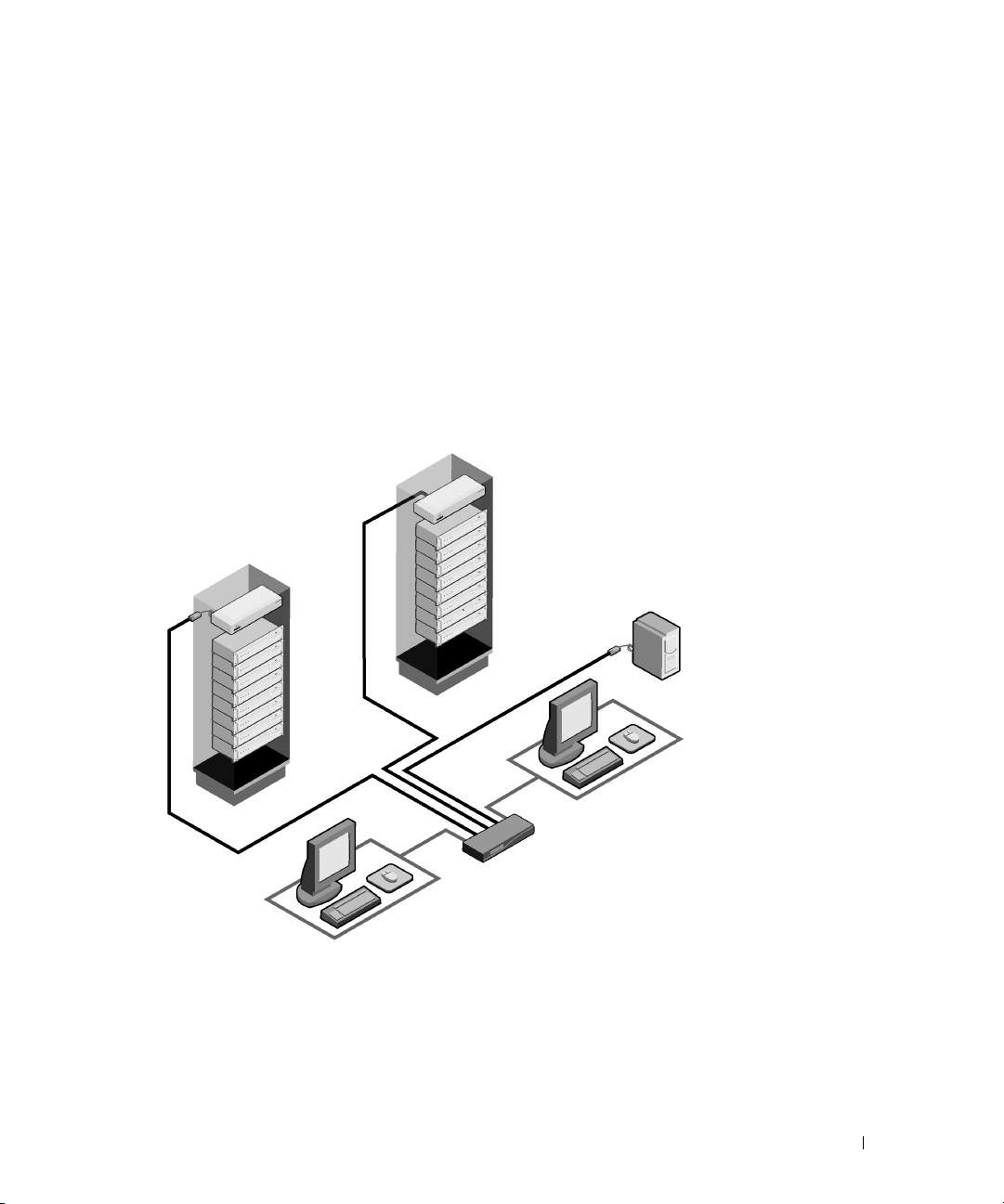
Figure 1-2. Example of a Console Switch Configuration
Console Switch
(tiered)
Legacy Switch
(tiered)
SIP
Module
Analog
Connection
Rack of Servers
Critical Server
Analog
Connection
Console Switch
(main)
Safety Precautions
Use the following safety guidelines to help ensure your own personal safety and to help protect your
system and working environment from potential damage.
Product Overview 9

CAUTION: The power supplies in your system may produce high voltages and energy hazards, which
can cause bodily harm. Only trained service technicians are authorized to remove the covers and
access any of the components inside the system.
This document pertains only to the Dell Console Switch.
General
• Observe and follow service markings:
• Do not service any product except as explained in your system documentation.
• Opening or removing covers that are marked with the triangular symbol with a lightning bolt
may expose you to electrical shock.
www.dell.com | support.dell.com
• Components inside these compartments should be serviced only by a trained service
technician.
– This product contains no serviceable components. Do not attempt to open.
• If any of the following conditions occur, unplug the product from the electrical outlet and
replace the part or contact your trained service provider:
– The power cable, extension cable, or plug is damaged.
– An object has fallen into the product.
– The product has been exposed to water.
– The product has been dropped or damaged.
– The product does not operate correctly when you follow the operating instructions.
• Keep your system away from radiators and heat sources. Also, do not block cooling vents.
• Do not spill food or liquids on your system components, and never operate the product in a
wet environment. If the system gets wet, see the appropriate section in your troubleshooting
guide or contact your trained service provider.
• Use the product only with approved equipment.
• Allow the product to cool before removing covers or touching internal components.
• Operate the product only from the type of external power source indicated on the electrical
ratings label. If you are not sure of the type of power source required, consult your service
provider or local power company.
NOTICE: To help avoid damaging your system, be sure the voltage selection switch (if provided) on the
power supply is set for the voltage that most closely matches the AC power available in your location.
• Be sure that your monitor and attached devices are electrically rated to operate with the
power available in your location.
• Use only power cables provided with this product.
10 Product Overview

• To help prevent electric shock, plug the system and peripheral power cables into properly
grounded electrical outlets. These cables are equipped with three-prong plugs to help ensure
proper grounding. Do not use adapter plugs or remove the grounding prong from a cable.
• Observe extension cable and power strip ratings. Make sure that the total ampere rating of all
products plugged into the power strip does not exceed 80 percent of the ampere ratings limit
for the power strip.
• To help protect your system from sudden, transient increases and decreases in electrical
power, use a surge suppressor, line conditioner, or uninterruptible power supply (UPS).
• Position system cables and power cables carefully. Route cables so that they cannot be stepped
on or tripped over. Be sure that nothing rests on any cables.
• Do not modify power cables or plugs. Consult a licensed electrician or your power company
for site modifications. Always follow your local/national wiring rules.
Rack Mounting of Systems
• Refer to the rack installation documentation accompanying the rack for specific caution
statements and procedures.
• System rack kits are intended to be installed in a rack by trained service technicians. If a nonDell rack is utilized, be sure that the rack meets the specifications of a Dell rack.
• Elevated Ambient Temperature: If installed in a closed rack assembly, the operation
temperature of the rack environment may be greater than room ambient. Use care not to
exceed the rated maximum ambient temperature of the unit.
• Reduced Air Flow: Installation of the equipment in a rack should be such that the amount of
airflow required for safe operation of the equipment is not compromised.
• Mechanical Loading: Mounting of the equipment in the rack should be such that a hazardous
condition is not achieved due to uneven mechanical loading.
• Circuit Overloading: Consideration should be given to the connection of the equipment to
the supply circuit and the effect that overloading of circuits might have on overcurrent
protection and supply wiring. Consider equipment nameplate ratings for maximum current.
• Reliable Earthing: Reliable earthing of rack mounted equipment should be maintained. Pay
particular attention to supply connections other than direct connections to the branch circuit
(for example, use of power strips).
Product Overview 11

www.dell.com | support.dell.com
12 Product Overview

Installation
Getting Started
Before installing your Console Switch, refer to the following list to ensure you have all items that
shipped with the appliance as well as other items necessary for proper installation.
Supplied with the Console Switch
The following are supplied with the Console Switch:
• Console Switch appliance
•Power cord
•CAT 5 cable
• Rack mounting kit
• 0U mounting bracket
•One serial cable
• Console Switch Installer/User’s Guide
• Console Switch Quick Installation Guide
2
Additional Items Needed
The following are additional items you may need to install your Console Switch:
• One Server Interface Pod (SIP) module and UTP cabling per attached server or switch
• 1U mounting (optional)
Rack Mounting Your Console Switch Unit
Obtain a Switch Mounting Bracket Kit (0U or 1U) to rack-mount your Console Switch unit.
Before installing the Console Switch and other components in the rack, stabilize the rack in a
permanent location. Start rack mounting your equipment at the bottom of the rack, then work
to the top. Avoid uneven loading or overloading of racks.
Installation 13
CAUTION: Before installing systems in a rack, install front and side stabilizers on stand-alone racks or
the front stabilizer on racks joined to other racks. Failure to install stabilizers accordingly before
installing systems in a rack could cause the rack to tip over, potentially resulting in bodily injury under
certain circumstances. Therefore, always install the stabilizer(s) before installing components in the
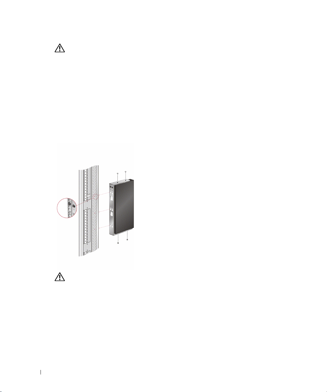
rack.To install the 0U switch mounting bracket (shipped as default):
Line up the holes of the mounting brackets with the screw holes in the switch.
1
2 Fasten the mounting bracket to the switch using the button head socket cap screws on
each side.
3 Mount the switch assembly to the rack by inserting the three mounting hooks on one side
of the bracket into square holes in the vertical rack.
4
Press down until the blue push button pops out and clicks.
www.dell.com | support.dell.com
Figure 2-1. OU Mounting Bracket Installation
To install the 1U four point switch mounting bracket:
1 Remove the screws on each side of the 1U four-point switch and set them aside to attach
2 Line up the vent holes in the “long side” of the kit’s front brackets with the vent holes in
14 Installation
CAUTION: Rack Loading - Overloading or uneven loading of racks may result in shelf or rack failure,
causing damage to equipment and possible personal injury. Stabilize racks in a permanent location
before loading begins. Mount components beginning at the bottom of the rack, then work to the top. Do
not exceed your rack load rating.
to the front 1U bracket pieces later.
the switch.

3 Line up the screw holes in the bracket with the screw holes in the switch.
4 With a Phillips screwdriver, fasten the front mounting brackets to the switch using two
screws on each side.
5 Attach four cage nuts or clip nuts to the rack mounting flange of the rack cabinet’s front so
that the nut is positioned on the inside of the rack.
6 Mount the switch assembly to the rack cabinet by matching the holes in the “short side” of
each bracket to an appropriate set of matching holes on your rack cabinet. Next, insert the
combination hex head screws through the slots in the bracket, then the holes in the
mounting rail, and then into the cage nuts or clip nuts.
7 Attach four cage nuts or clip nuts to the rack mounting flange of the rack cabinet back so
that the nut is positioned on the inside of the rack.
8 Slide the rear brackets into the channel of the front brackets adjusting them to fit the rack
depth.
9 Mount the rear bracket to the rack cabinet by matching the holes in the “short side” of
each bracket to an appropriate set of matching holes on your rack cabinet, ensuring the
switch is level within the rack.
10
Insert the combination hex head screws through the slots in the bracket and the holes in the
mounting rail, then into the cage nuts or clip nuts.
Installation 15
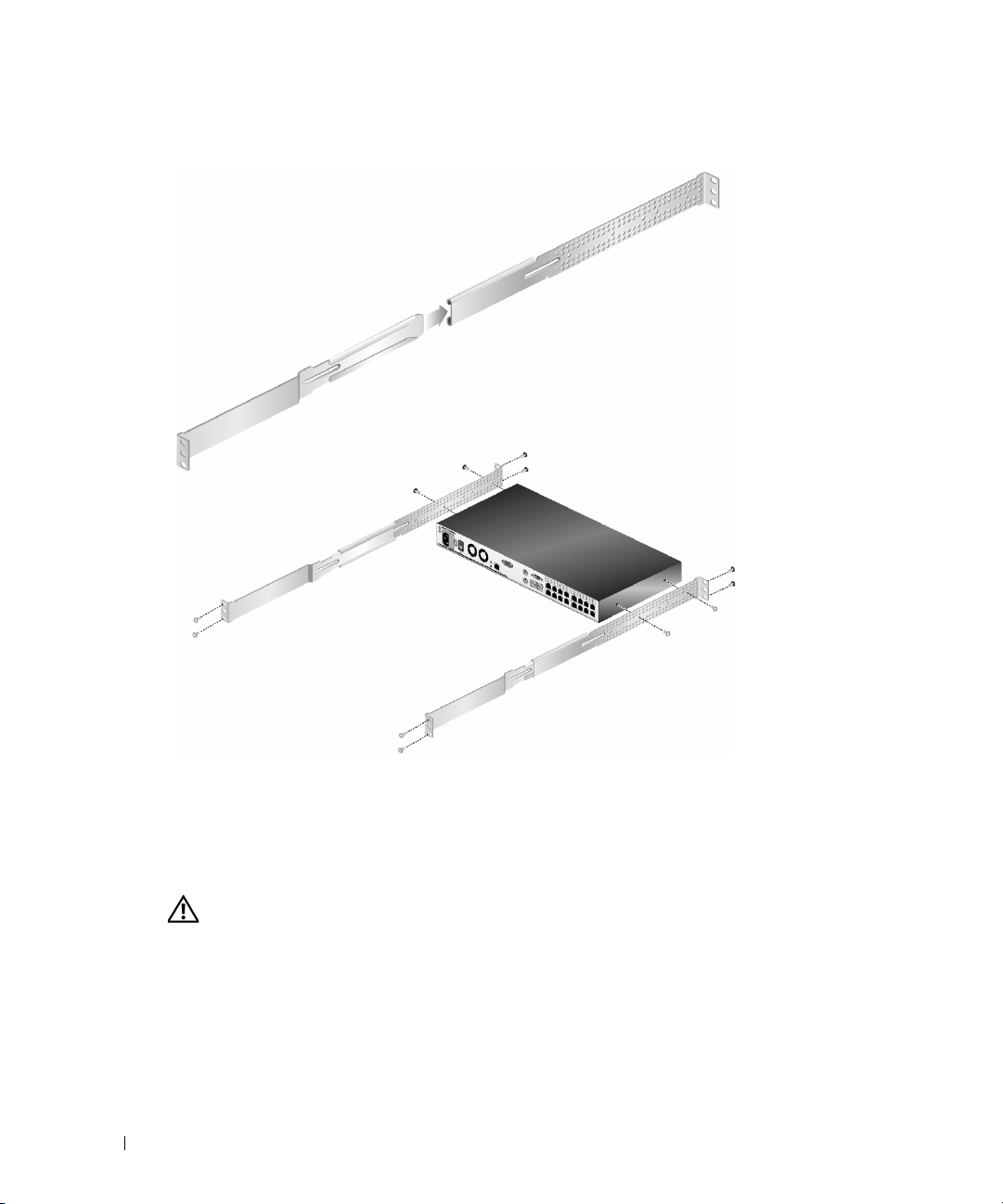
Figure 2-2. 1U Installation
www.dell.com | support.dell.com
Installing the Console Switch
Plug the supplied power cord into the back of the appliance and then into an appropriate power
source. Figure 2-3 illustrates one possible configuration for your Console Switch. See the following
detailed set of procedures to successfully install your appliance.
CAUTION: To reduce the risk of electric shock or damage to your equipment:
16 Installation
- Do not disable the power cord grounding plug. The grounding plug is an important safety feature.
- Plug the power cord into a grounded (earthed) outlet that is easily accessible at all times.
- Power down the unit by unplugging the power cord from the electrical outlet or the unit.
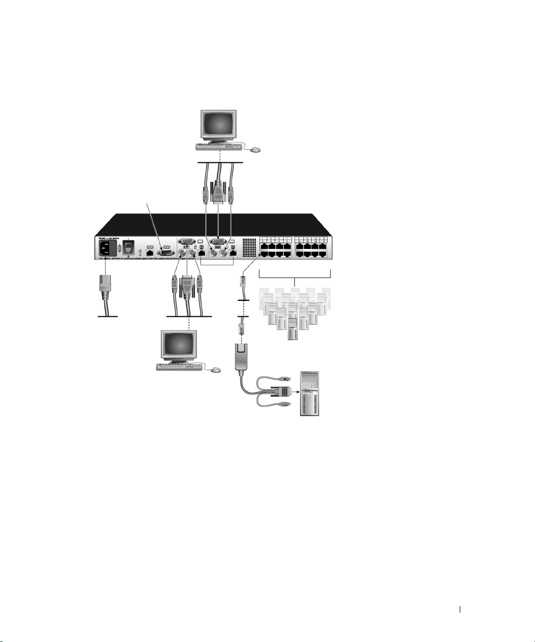
Figure 2-3. Basic Console Switch Configuration
Local User B (16-port model only)
Configuration Port
(for updating firmware)
Console Switch
Servers 2-16
Local User A
SIP
Server 1
To connect a SIP to each server:
1
Locate the SIPs for your Console Switch.
2
Attach the appropriately cable ends to the keyboard, monitor and mouse ports on the first server
you will be connecting to the appliance.
3
Attach one end of the CAT 5 cabling that will run between your SIP and Console Switch to
the RJ-45 connector on the SIP.
4
Connect the other end of the CAT 5 cable to the desired ARI port on the back of your
Console Switch.
5
Repeat steps 2 to 4 for all servers you wish to attach.
Installation 17

NOTE: When connecting a Sun AVRIQ module, you must use a multi-sync monitor to accommodate Sun
computers that support both VGA and sync-on-green or composite sync.
To connect local peripherals:
1
Select the keyboard, monitor and mouse to be connected to local user A.
2
Locate the port set labeled A on the back of the appliance. Connect these peripherals to their
respective ports.
NOTE: For the multiuser, 16-port Console Switch, repeat these steps for the local user analog port set
labeled B.
3
Bundle and label the cables for easy identification.
www.dell.com | support.dell.com
Tiering Console Switches
You can tier multiple Console Switches to enable one or two users to connect to up to 256 servers.
In a tiered system, each Analog Rack Interface (ARI) port on the main Console Switch will connect
to the Analog Console Interface (ACI) port on each tiered Console Switch. Each tiered switch can
then be connected to a server with a SIP. The example in Figure 2-1 shows one Console Switch
tiered under the main switch, enabling the connection of up to 15 primary servers and 16 secondary
servers. Using this configuration, you can tier 16 Console Switches under the main switch, enabling
the connection of up to 256 servers. Only one level of tiering is supported in this type of
configuration, which means that you cannot tier additional legacy switches or another Console
Switch. In this configuration, the local port On-Screen Configuration and Activity Reporting
(OSCAR®) interface of the tiered Console Switch is disabled. All functions are performed through
the main Console Switch OSCAR.
NOTE: As shown in Figure 2-1, only local user A’s ACI port may be used for the tiered connection.
To tier multiple Console Switches:
1
Connect the Console Switch (tiered) to each server as described in the previous "Installing
the Console Switch" section.
2
Connect the local peripherals to local user A of the main switch as described in "Installing the
Console Switch" .
3
Attach one end of the CAT 5 cabling that will run between your main and tiered Console
Switch to the RJ-45 (ACI) connector of local user A on the tiered Console Switch.
4
Attach the other end of the CAT 5 cable to one of the 16 RJ-45 (ARI) ports on the main
Console Switch.
NOTE: The system will automatically tier the two switches together as one. All servers connected to the
5
18 Installation
tiered Console Switch will display on the main Console Switch server list in the OSCAR interface.
Repeat steps 3 and 4 for all additional tiered (secondary) Console Switches you wish to
attach.
 Loading...