

DELL Inspiron 8500, Inspiron 8600 Service Manual

Please check out our eBay auctions for more great
deals on Factory Service Manuals:

Dell Inspiron 8500/8600 Service Manual
Dell™ Inspiron™ 8500/8600 Service Manual
Before You Begin
System Components
Memory Module, Mini PCI Card, Modem, and Modules
Color Insert Cover
Hard Drive
Bluetooth™ Card
Fan
Docking Doors
Keyboard
Display Assembly
Video Card
Microprocessor Thermal-Cooling Assembly
Palm Rest
Microprocessor Module
Flashing the BIOS
Reserve Battery
System Board
Speakers
Base Latch
Pin Assignments for I/O Connectors
Notes, Notices, and Cautions
NOTE: A NOTE indicates important information that helps you make better use of your
computer.
NOTICE: A NOTICE indicates either potential damage to hardware or loss of data and tells you
how to avoid the problem.
CAUTION: A CAUTION indicates a potential for property damage, personal injury, or
death.
Information in this document is subject to change without notice.
© 2003 Dell Inc. All rights reserved.
Reproduction in any manner whatsoever without the written permission of Dell Inc. is strictly forbidden.
file:///I|/SERVICE%20MANUALS/DELL%20MANUALS...WITH%20PARALLEL%20SERIAL_SERV_MAN/index.htm (1 of 2)6/21/2004 1:12:13 AM

Dell Inspiron 8500/8600 Service Manual
Trademarks used in this text: Dell, the DELL logo, and Inspiron are trademarks of Dell Inc.; Intel is a registered trademark
of Intel Corporation; Microsoft and Windows are registered trademarks of Microsoft Corporation; Bluetooth is a trademark
owned by Bluetooth SIG, Inc. and is used by Dell Inc. under license.
Other trademarks and trade names may be used in this document to refer to either the entities claiming the marks and
names or their products. Dell Inc. disclaims any proprietary interest in trademarks and trade names other than its own.
Model PP02X
August 2003 Rev. A02
file:///I|/SERVICE%20MANUALS/DELL%20MANUALS...WITH%20PARALLEL%20SERIAL_SERV_MAN/index.htm (2 of 2)6/21/2004 1:12:13 AM
Before You Begin: Dell Inspiron 8500/8600 Service Manual
Back to Contents Page
Before You Begin
Dell™ Inspiron™ 8500/8600 Service Manual
Preparing to Work Inside the Computer
Recommended Tools
Computer Orientation
Screw Identification
Preparing to Work Inside the Computer
CAUTION: Only a certified service technician should perform repairs on your
computer. Damage due to servicing that is not authorized by Dell is not covered by
your warranty. Read and follow applicable instructions in the safety instructions in
the Owner's Manual that came with the computer.
CAUTION: To prevent static damage to components inside your computer, discharge
static electricity from your body before you touch any of your computer's electronic
components. You can do so by touching an unpainted metal surface.
CAUTION: Handle components and cards with care. Do not touch the components or
contacts on a card. Hold a card by its edges or by its metal mounting bracket. Hold a
component such as a microprocessor by its edges, not by its pins.
NOTICE: To avoid damaging the computer, perform the following steps before you begin
working inside the computer.
1. Ensure that the work surface is flat and clean to prevent scratching the computer cover.
2. Save any work in progress and exit all open programs.
3. Turn off the computer and all attached devices.
NOTE: Ensure that the computer is off and not in a power management mode. If you cannot
shut down the computer using the computer operating system, press and hold the power button
for 4 seconds.
4. If the computer is connected to a docking station, undock it.
5. Disconnect the computer from the electrical outlet.
file:///I|/SERVICE%20MANUALS/DELL%20MANUALS...WITH%20PARALLEL%20SERIAL_SERV_MAN/begin.htm (1 of 7)6/21/2004 1:12:15 AM
Before You Begin: Dell Inspiron 8500/8600 Service Manual
6. To avoid possible damage to the system board, wait 10 to 20 seconds and then disconnect any
attached devices.
7. Disconnect all other external cables from the computer.
8. Remove any installed PC Cards from the PC Card slot.
9. Close the display and turn the computer upside down on a flat work surface.
NOTICE: To avoid damaging the system board, you must remove the main battery before you
service the computer.
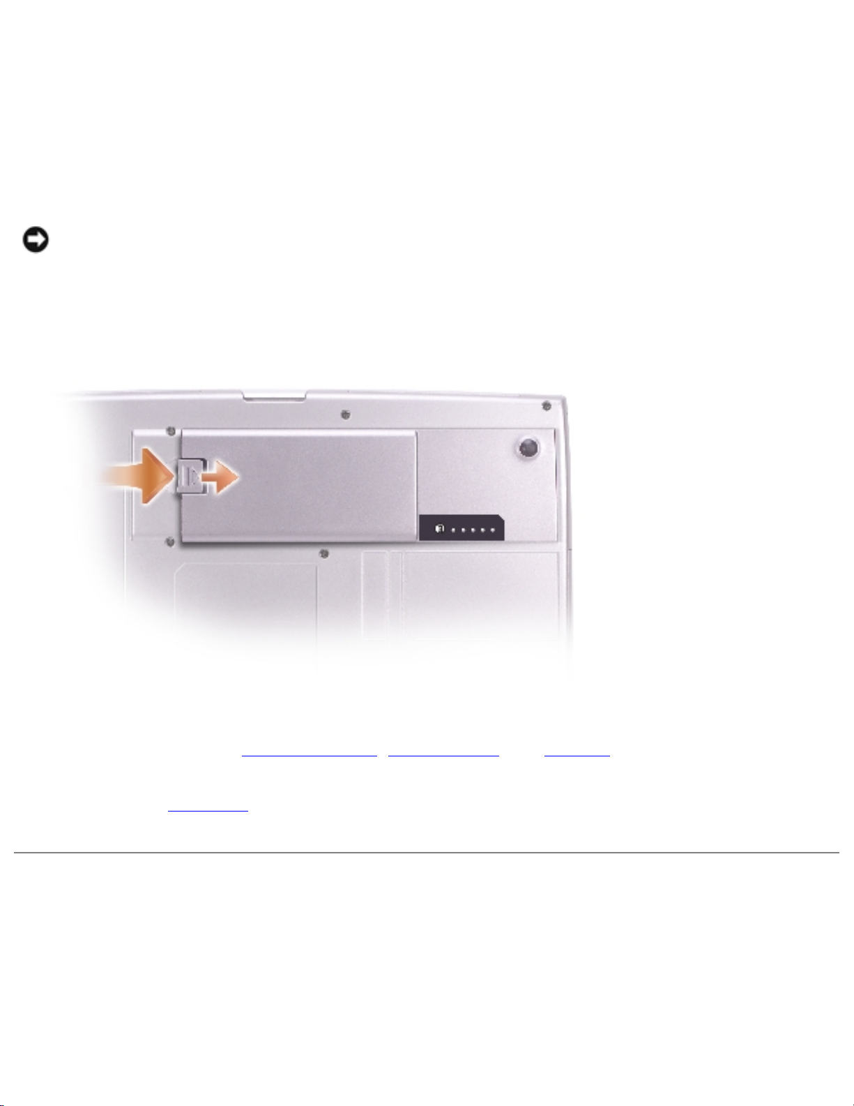
10. Slide and hold the battery-bay latch release on the bottom of the computer, and then remove
the battery from the bay.
11. Remove any installed memory modules, Mini PCI cards, and modules, including a second battery
if one is installed.
12. Remove the hard drive.
Recommended Tools
The procedures in this manual require the following tools:
● #1 Phillips screwdriver
● ¼-inch flat-blade screwdriver
file:///I|/SERVICE%20MANUALS/DELL%20MANUALS...WITH%20PARALLEL%20SERIAL_SERV_MAN/begin.htm (2 of 7)6/21/2004 1:12:15 AM
Before You Begin: Dell Inspiron 8500/8600 Service Manual
● Small plastic scribe
● Flash BIOS update program floppy disk or CD
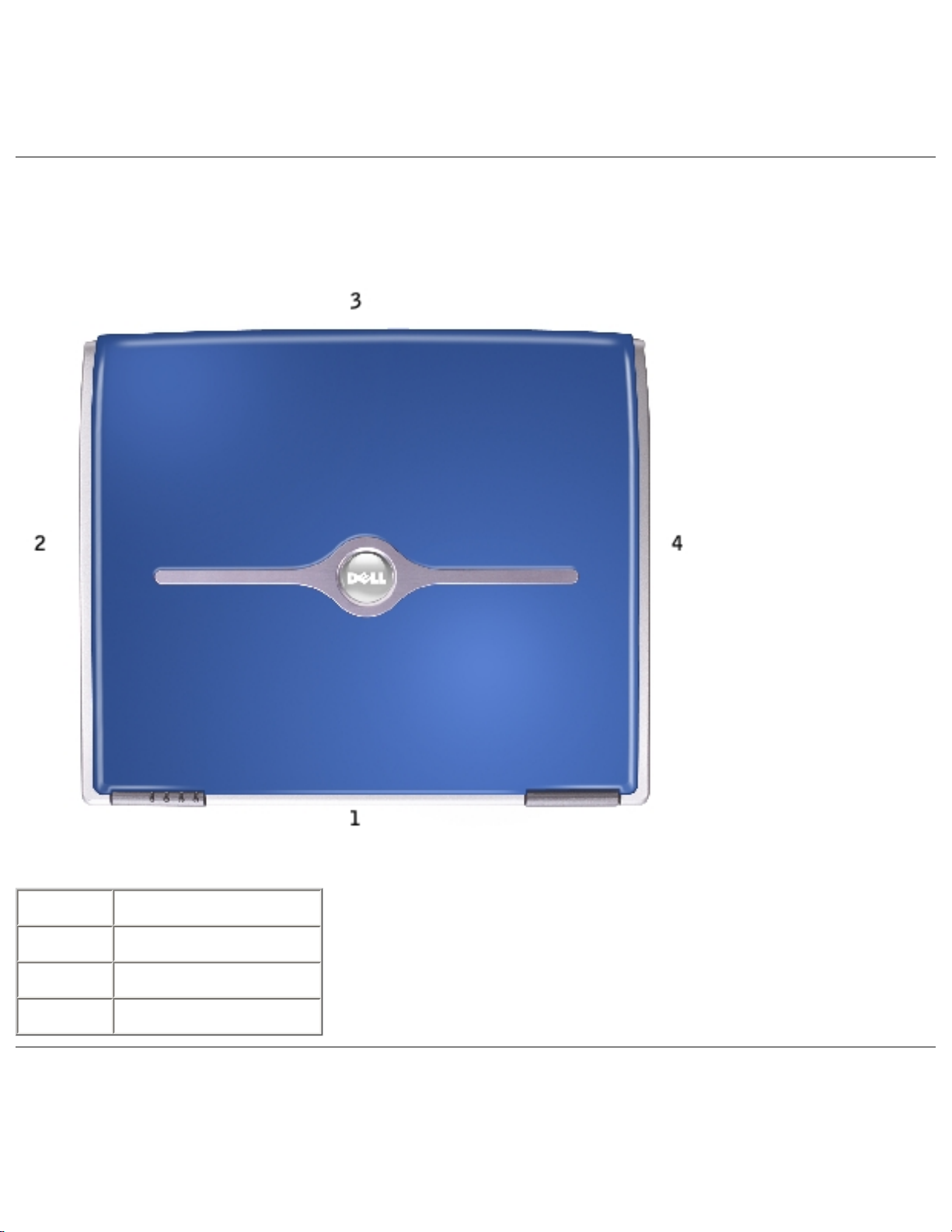
Computer Orientation
1 back
2 right
3 front
4 left
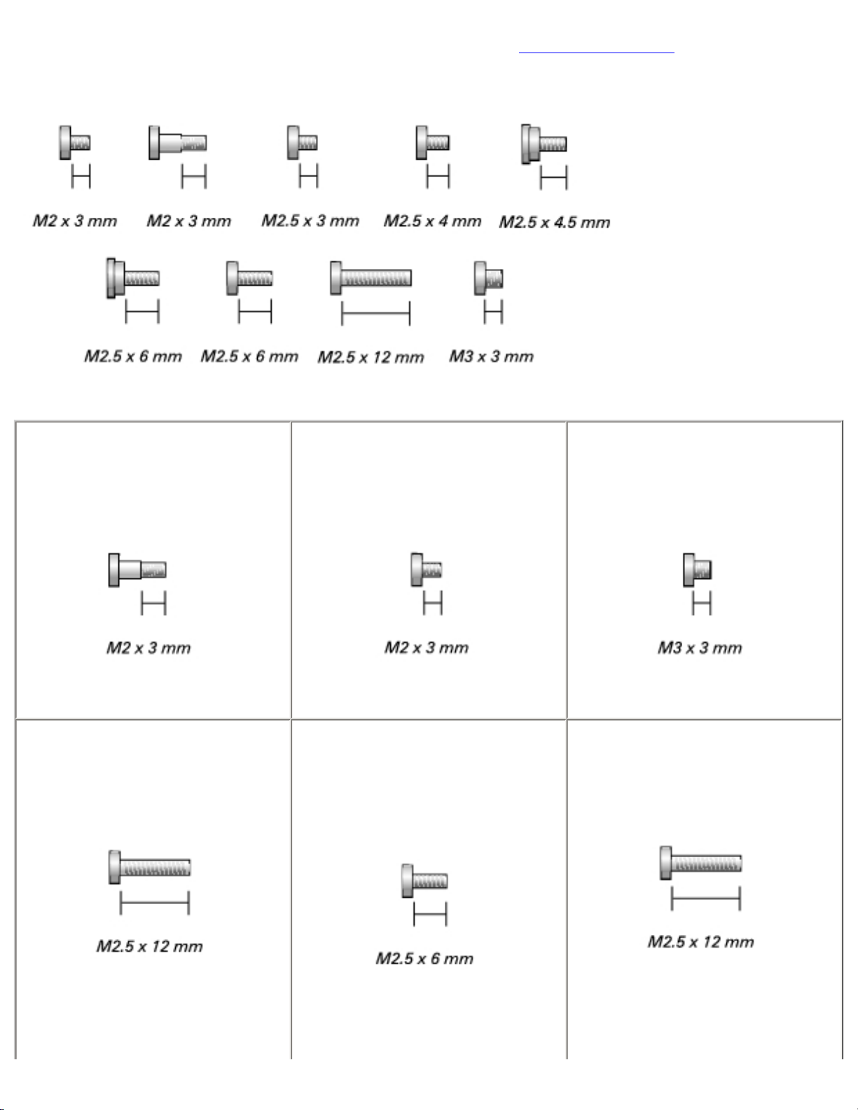
Screw Identification
file:///I|/SERVICE%20MANUALS/DELL%20MANUALS...WITH%20PARALLEL%20SERIAL_SERV_MAN/begin.htm (3 of 7)6/21/2004 1:12:15 AM
Before You Begin: Dell Inspiron 8500/8600 Service Manual
When you are removing and replacing components, photocopy "Screw Identification" as a tool to lay out
and keep track of the screws. The placemat provides the number of screws and their sizes.
Optional Module:
(1 each)
Modem:
(1 each)
Hard Drive:
(1 each)
Fan:
(2 each)
Keyboard:
(2 each)
Display Assembly:
(2 each)
file:///I|/SERVICE%20MANUALS/DELL%20MANUALS...WITH%20PARALLEL%20SERIAL_SERV_MAN/begin.htm (4 of 7)6/21/2004 1:12:15 AM
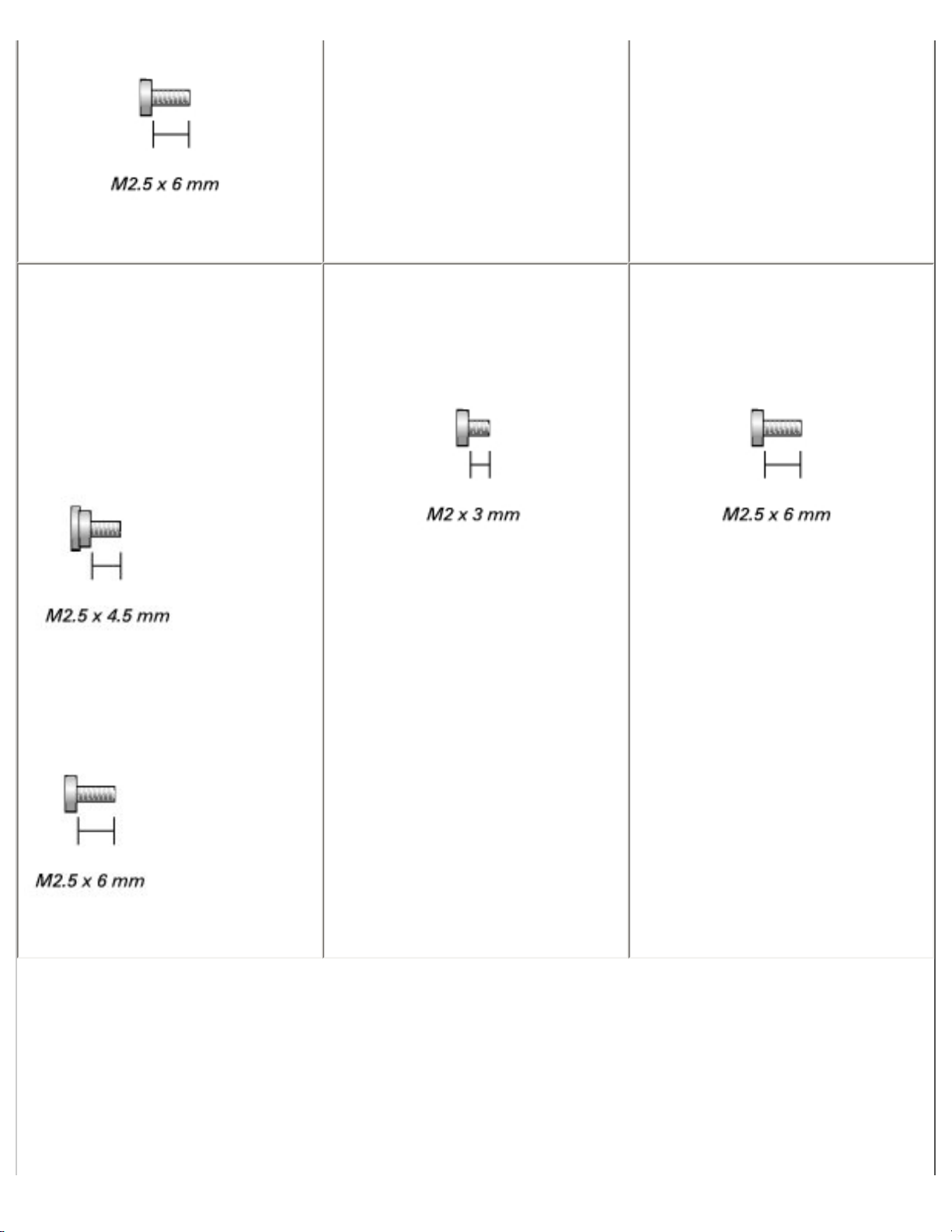
Before You Begin: Dell Inspiron 8500/8600 Service Manual
Display Bezel:
(shoulder screw covers, 2 each)
(display bumpers, 6 each)
(2 each)
(6 each)
Display Panel:
(9 each)
Display Latch:
(2 each)
file:///I|/SERVICE%20MANUALS/DELL%20MANUALS...WITH%20PARALLEL%20SERIAL_SERV_MAN/begin.htm (5 of 7)6/21/2004 1:12:15 AM
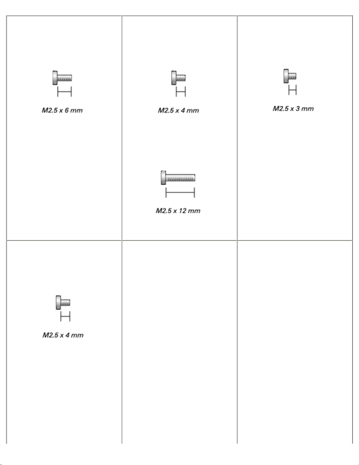
Before You Begin: Dell Inspiron 8500/8600 Service Manual
Video Card
(4 each)
Palm Rest:
(2 each)
(13 each)
Speakers:
(1 each)
System Board:
(3 each)
(2 each)
file:///I|/SERVICE%20MANUALS/DELL%20MANUALS...WITH%20PARALLEL%20SERIAL_SERV_MAN/begin.htm (6 of 7)6/21/2004 1:12:15 AM
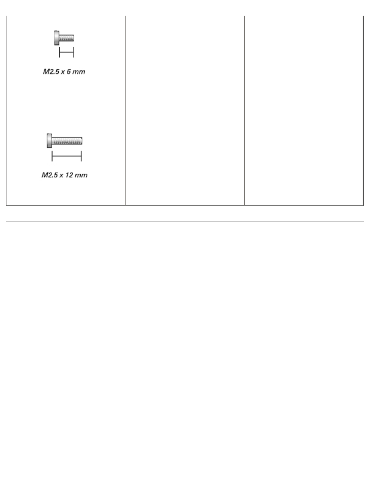
Before You Begin: Dell Inspiron 8500/8600 Service Manual
(1 each)
Back to Contents Page
file:///I|/SERVICE%20MANUALS/DELL%20MANUALS...WITH%20PARALLEL%20SERIAL_SERV_MAN/begin.htm (7 of 7)6/21/2004 1:12:15 AM
System Components: Dell Inspiron 8500/8600 Service Manual
Back to Contents Page
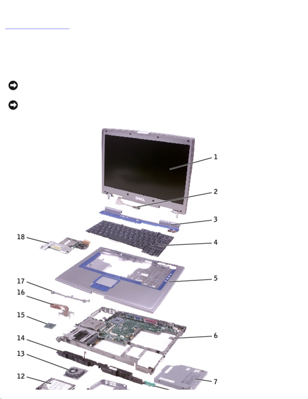
System Components
Dell™ Inspiron™ 8500/8600 Service Manual
NOTICE: Only a certified service technician should perform repairs on your computer. Damage
due to servicing that is not authorized by Dell is not covered by your warranty.
NOTICE: Unless otherwise noted, each procedure in this document assumes that a part can be
replaced by performing the removal procedure in reverse order.
file:///I|/SERVICE%20MANUALS/DELL%20MANUALS...ITH%20PARALLEL%20SERIAL_SERV_MAN/system.htm (1 of 2)6/21/2004 1:12:16 AM

System Components: Dell Inspiron 8500/8600 Service Manual
1 display assembly 10 battery
2 display cable 11 release latch
3 center control cover 12 hard drive
4 keyboard 13 fan
5 palm rest 14 speakers
6 system board assembly 15 microprocessor
7 optical drive 16 thermal cooling assembly
8 reserve battery 17 system board support
9 computer base 18 video card
Back to Contents Page
file:///I|/SERVICE%20MANUALS/DELL%20MANUALS...ITH%20PARALLEL%20SERIAL_SERV_MAN/system.htm (2 of 2)6/21/2004 1:12:16 AM
Memory Module, Mini PCI Card, Modem, and Modules: Dell Inspiron 8500/8600 Service Manual
Back to Contents Page
Memory Module, Mini PCI Card, Modem, and
Modules
Dell™ Inspiron™ 8500/8600 Service Manual
Memory Module
Mini PCI Card
Modem
Modules
Memory Module
CAUTION: Before working inside your Dell™ computer, read the safety instructions in
your Owner's Manual.
CAUTION: To prevent static damage to components inside your computer, discharge
static electricity from your body before you touch any of your computer's electronic
components. You can do so by touching an unpainted metal surface.
NOTE: Memory modules purchased from Dell are covered under your computer
warranty.
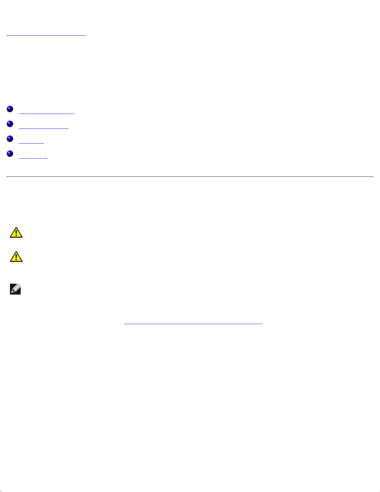
1. Follow the instructions in "Preparing to Work Inside the Computer."
2. Turn the computer over, loosen the captive screw from the memory module cover, and lift the
cover.
file:///I|/SERVICE%20MANUALS/DELL%20MANUALS...H%20PARALLEL%20SERIAL_SERV_MAN/upgrades.htm (1 of 13)6/21/2004 1:12:19 AM
Memory Module, Mini PCI Card, Modem, and Modules: Dell Inspiron 8500/8600 Service Manual
1 captive screw
2 memory module cover
NOTICE: To prevent damage to the memory module connector, do not use tools to spread the
inner metal tabs that secure the memory module.
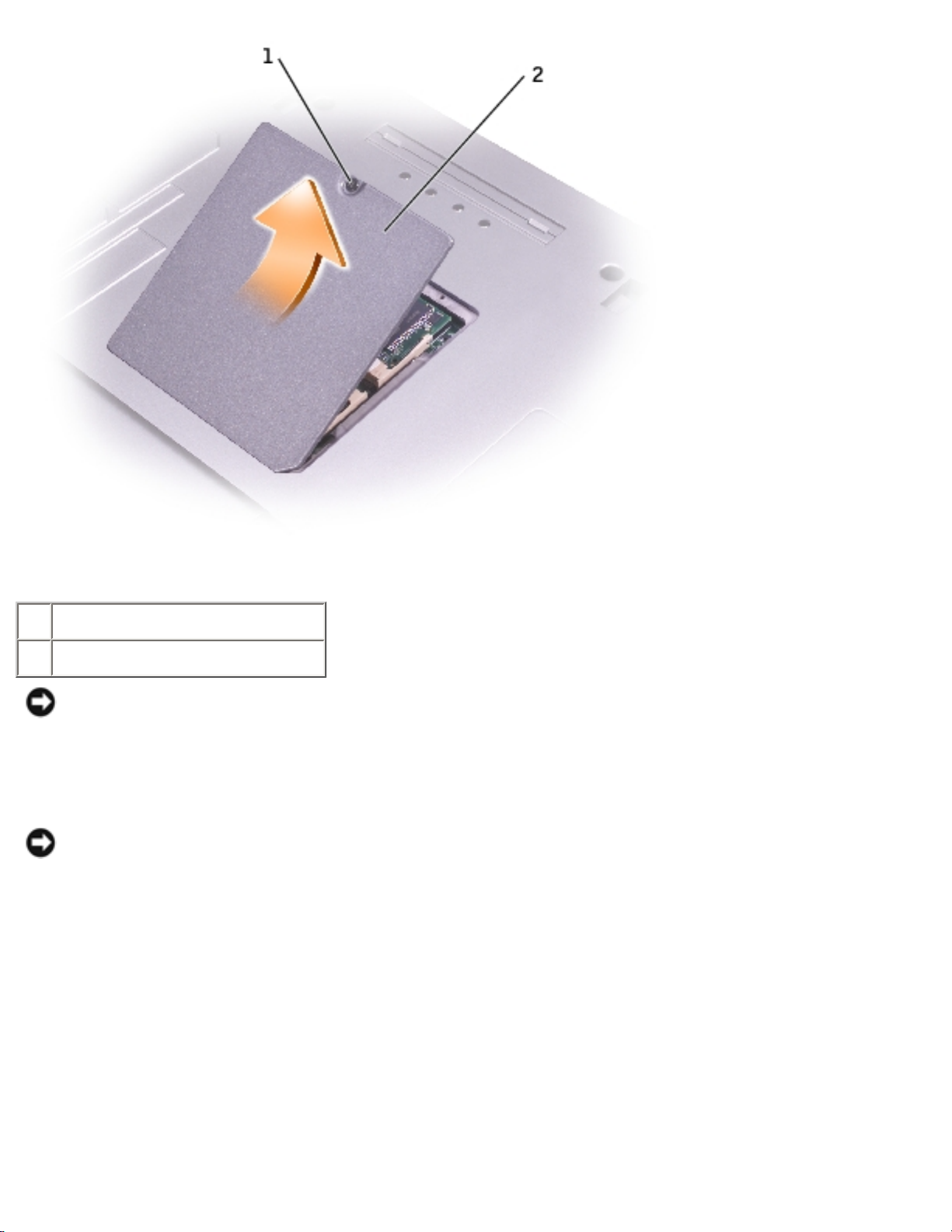
3. If you are replacing a memory module, remove the existing module.
NOTICE: Handle memory modules by their edges, and do not touch the components on a
module.
a. Use your fingertips to carefully spread apart the securing clips on each end of the
memory module connector until the module pops up.
b. Remove the module from the connector.
file:///I|/SERVICE%20MANUALS/DELL%20MANUALS...H%20PARALLEL%20SERIAL_SERV_MAN/upgrades.htm (2 of 13)6/21/2004 1:12:19 AM
Memory Module, Mini PCI Card, Modem, and Modules: Dell Inspiron 8500/8600 Service Manual
1 securing clips (2 per
connector)
2 memory module
NOTICE: If you need to install memory modules in two connectors, install a memory module in
the connector labeled "DIMMA (Slot 1)" before you install a module in the connector labeled
"DIMMB."
4. Ground yourself and install the new memory module:
a. Align the notch in the module with the slot in the center of the connector.
b. Slide the edge of the module firmly into the connector, and rotate the module down until
you feel a click. If you do not feel the click, remove the module and reinstall it.
NOTE: If the memory module is not installed properly, the computer does not boot. The Num
Lock and Scroll Lock lights blink about ten times.
5. Replace the cover and screw.
NOTICE: If the memory module cover is difficult to close, remove the module and reinstall it.
Forcing the cover to close may damage your computer.
file:///I|/SERVICE%20MANUALS/DELL%20MANUALS...H%20PARALLEL%20SERIAL_SERV_MAN/upgrades.htm (3 of 13)6/21/2004 1:12:19 AM

Memory Module, Mini PCI Card, Modem, and Modules: Dell Inspiron 8500/8600 Service Manual
6. Insert the battery into the battery bay, or connect the AC adapter to your computer and an
electrical outlet.
7. Turn on the computer.
As the computer boots, it detects the additional memory and automatically updates the system
configuration information.
Mini PCI Card
If you ordered a Mini PCI card at the same time that you ordered your computer, Dell has already
installed the card for you.
CAUTION: Before working inside your computer, read the safety instructions in your
Owner's Manual.
CAUTION: To prevent static damage to components inside your computer, discharge
static electricity from your body before you touch any of your computer's electronic
components. You can do so by touching an unpainted metal surface.
NOTICE: Handle components and cards by their edges, and avoid touching pins and
contacts.
1. Follow the instructions in "Preparing to Work Inside the Computer."
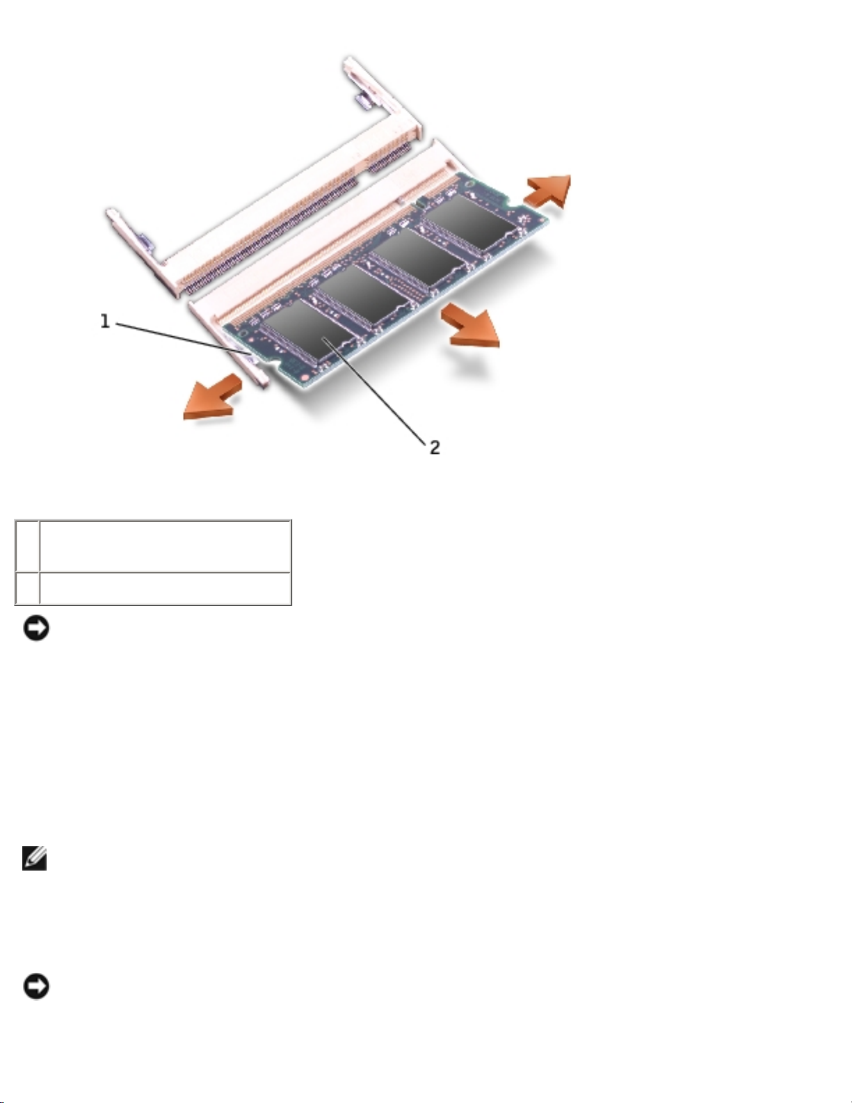
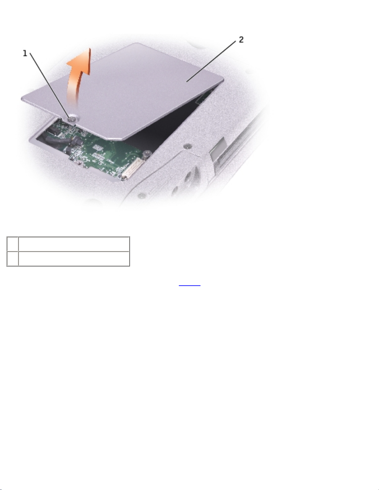
2. Turn the computer over, and loosen the captive screw on the Mini PCI card/modem cover.
file:///I|/SERVICE%20MANUALS/DELL%20MANUALS...H%20PARALLEL%20SERIAL_SERV_MAN/upgrades.htm (4 of 13)6/21/2004 1:12:19 AM
Memory Module, Mini PCI Card, Modem, and Modules: Dell Inspiron 8500/8600 Service Manual
1 captive screw
2 Mini PCI card/modem cover
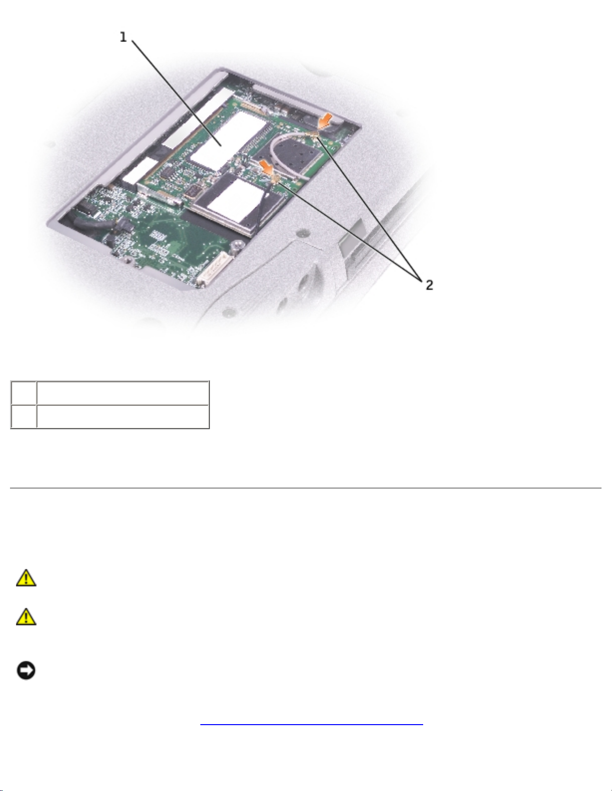
3. If a Mini PCI card is not already installed, go to step 4. If you are replacing a Mini PCI card,
remove the existing card:
a. Disconnect the Mini PCI card from any attached cables.
b. Release the Mini PCI card by spreading the metal securing tabs until the card pops up
slightly.
c. Lift the Mini PCI card out of its connector.
file:///I|/SERVICE%20MANUALS/DELL%20MANUALS...H%20PARALLEL%20SERIAL_SERV_MAN/upgrades.htm (5 of 13)6/21/2004 1:12:19 AM

Memory Module, Mini PCI Card, Modem, and Modules: Dell Inspiron 8500/8600 Service Manual
1 Mini PCI card connector
2 Mini PCI card
3 antenna cables (2)
NOTICE: To avoid damaging the Mini PCI card, never place cables on top of or under the
card.
NOTICE: The connectors are keyed to ensure correct insertion. If you feel resistance, check
the connectors and realign the card.
4. Align the Mini PCI card with the connector at a 45-degree angle, and press the Mini PCI card
firmly into the connector, and press down until you feel a click.
5. Connect the antenna cables to the Mini PCI.
file:///I|/SERVICE%20MANUALS/DELL%20MANUALS...H%20PARALLEL%20SERIAL_SERV_MAN/upgrades.htm (6 of 13)6/21/2004 1:12:19 AM
Memory Module, Mini PCI Card, Modem, and Modules: Dell Inspiron 8500/8600 Service Manual
1 Mini PCI card
2 antenna cables (2)
6. Replace the cover and tighten the screw.
Modem
CAUTION: Before working inside your computer, read the safety instructions in your
Owner's Manual.
CAUTION: To prevent static damage to components inside your computer, discharge
static electricity from your body before you touch any of your computer's electronic
components. You can do so by touching an unpainted metal surface.
NOTICE: Handle components and cards by their edges, and avoid touching pins and
contacts.
1. Follow the instructions in "Preparing to Work Inside the Computer."
2. Turn the computer over, and loosen the captive screw from the Mini PCI card/modem cover.
file:///I|/SERVICE%20MANUALS/DELL%20MANUALS...H%20PARALLEL%20SERIAL_SERV_MAN/upgrades.htm (7 of 13)6/21/2004 1:12:19 AM
Memory Module, Mini PCI Card, Modem, and Modules: Dell Inspiron 8500/8600 Service Manual
1 captive screw
2 Mini PCI card/modem cover
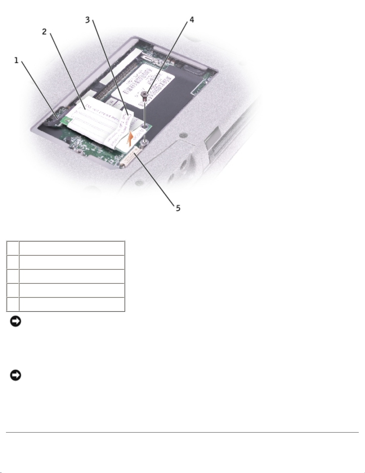
3. If a modem is not already installed, go to step 4. If you are replacing a modem, remove the
existing modem:
a. Remove the screws securing the modem to the system board, and set it aside.
b. Pull straight up on the attached pull-tab to lift the modem out of its connector on the
system board, and disconnect the modem cable.
file:///I|/SERVICE%20MANUALS/DELL%20MANUALS...H%20PARALLEL%20SERIAL_SERV_MAN/upgrades.htm (8 of 13)6/21/2004 1:12:19 AM
Memory Module, Mini PCI Card, Modem, and Modules: Dell Inspiron 8500/8600 Service Manual
1 modem cable
2 modem
3 pull-tab
4 screw
5 system board connector
NOTICE: The cable connectors are keyed for correct insertion; do not force the
connections.
4. Connect the modem cable to the modem.
NOTICE: To prevent damage to the modem, press the modem into the connector directly over
the connector.
5. Align the modem with the screw hole, and press the modem into the connector directly over the
connector on the system board.
file:///I|/SERVICE%20MANUALS/DELL%20MANUALS...H%20PARALLEL%20SERIAL_SERV_MAN/upgrades.htm (9 of 13)6/21/2004 1:12:19 AM

Memory Module, Mini PCI Card, Modem, and Modules: Dell Inspiron 8500/8600 Service Manual
Modules
Your computer ships with an optical drive installed in the module bay. However, the device screw is not
installed in the optical drive but packaged separately. When you install your device in the module bay,
you can install the device screw.
NOTE: You do not need to install the device screw unless you want to secure the module inside
the computer for security purposes.
If the Device Screw Is Not Installed
NOTICE: To prevent damage to devices, place them in a safe, dry place when they are not
installed in the computer. Avoid pressing down on them or placing heavy objects on top of
them.
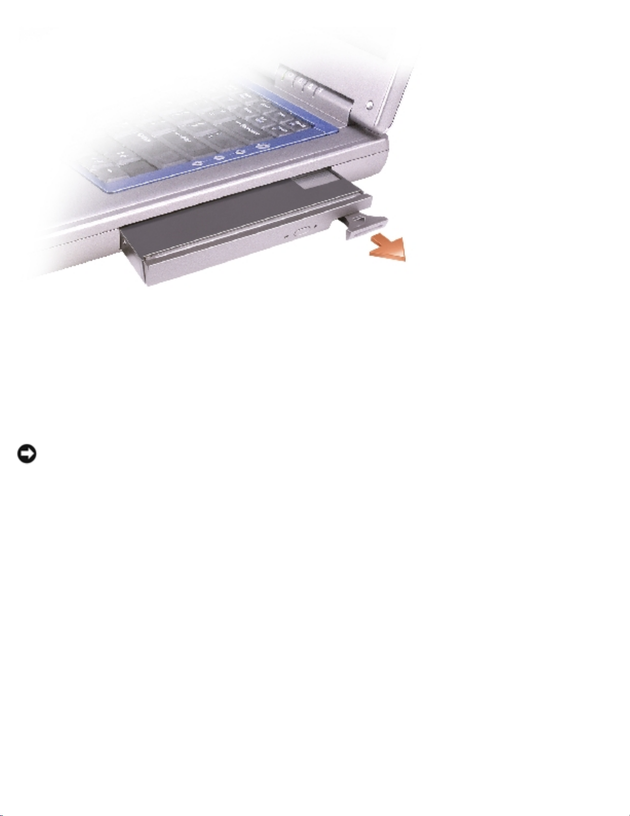
1. Press the device latch release so that the latch release pops out.
1 device latch release
2. Pull the device by the latch release to remove the device from the module bay.
file:///I|/SERVICE%20MANUALS/DELL%20MANUAL...%20PARALLEL%20SERIAL_SERV_MAN/upgrades.htm (10 of 13)6/21/2004 1:12:19 AM
Memory Module, Mini PCI Card, Modem, and Modules: Dell Inspiron 8500/8600 Service Manual
If the Device Screw Is Installed
1. If the computer is connected to a docking device (docked), undock it. See the documentation
that came with your docking device for instructions.
NOTICE: To prevent damage to devices, place them in a safe, dry place when they are not
installed in the computer. Avoid pressing down on them or placing heavy objects on top of
them.
2. Close the display and turn the computer over.
3. Use a #1 Phillips screwdriver to remove the M2 x 3-mm screw from the bottom of the
computer.
file:///I|/SERVICE%20MANUALS/DELL%20MANUAL...%20PARALLEL%20SERIAL_SERV_MAN/upgrades.htm (11 of 13)6/21/2004 1:12:19 AM
 Loading...